c~ '-r1 ~d --i o · 80 percent smys in class i locations provided that the conditions and...
TRANSCRIPT
--i
1200 New Jersey Ave SEUS Department Washington DC 20590 of Transportation Pipeline and Hazardous Materials Safety
April 30 2009Administration
C~ -r1 ~D
o Mr Walter Bennett Jc- --1--
Senior Vice President of Operations Boardwalk Pipeline Partners LP 9 Greenway Plaza Suite 2800 Houston Texas 77046
Dear Mr Bennett
The enclosed Agreement modifies the special permits the Pipeline and Hazardous Materials Safety Administration (PHMSA) issued to Boardwalk Pipeline Partners LP and its subsidiaries Gulf Crossing Pipeline Company LLC Gulf South Pipeline Company LP and Texas Gas Transmission LLC (collectively hereinafter Boardwalk) to operate certain pipelines at up to 80 percent SMYS in Class I locations provided that the conditions and safety requirements set forth in each of the special permits were met The request letters Federal Register notices and all other pertinent documents are available for review in Docket Nos PHMSA- 2006-26533 PHMSA- 2007-28994 PHMSA- 2008-0068 PHMSA- 2008-0067 and PHMSA- 2006-26533 in the Federal Docket Management System (FOMS) located on the internet at wwwRegulationsgov The Boardwalk pipelines that received special permits are located in Louisiana Texas Mississippi Arkansas Oklahoma and Alabama and include the 42-inch East Texas to Mississippi Pipeline the 42-inch Mississippi Loop Pipeline the 42-inch South East Pipeline the 42-inch Gulf Crossing Pipeline the 36-inch Fayetteville Lateral and the 36-inch Greeneville Lateral (collectively referred to as Pipelines)
As you know subsequent to the issuance of these special permits Boardwalk reported to PHMSA that certain anomalies had been discovered in the Pipelines Specifically some of the X70 grade steel pipe used in constructing these pipelines appear to have exhibited low yield strength below the minimum level allowed by American Petroleum Institute Specification 5L Specification for Line Pipe (API SL) During the process of testing segments of the Mississippi Loop project a hydrostatic test failure occurred in which the root cause was determined to be a switched plate inadvertently inserted into the plate rolling in the plate mill As a result of the hydrostatic test failure Boardwalk in cooperation with PHMSA ran deformation tools in all of the subject pipelines Boardwalk has discovered anomalies in the Pipelines that appear not to be directly related to the initial root cause findings for the Mississippi Loop failure
After being informed of these issues hy Boardwalk PHMSA initiated an inquiry and took immediate steps including field inspections and information collection Through a number of meetings and conference calls PHMSA expressed its concerns and Boardwalk took immediate
Page 2 Mr Walter Bennett Boardwalk Pipeline Partners LP
steps to ensure the specified pipelines could be safely operated Boardwalk is continuing its investigation formulating a remediation fitness for purpose plan including the potential excavation and removal of certain anomalous pipe joints We acknowledge Boardwalks cooperation and commitment to performing corrective actions in response to PHMSAs concerns The enclosed Agreement modifies the special permits by specifying interim pressure limits and other remedial actions in order to conservatively address the potentially low yield strength issues PHMSA has determined are necessary prior to implementing the alternative MAOP and to prudently operate the Pipelines The Agreement must be signed and returned to PHMSA within 10 days of your receipt of this letter
As the actions required under the Agreement are implemented Boardwalk must review these operating parameters with PHMSA and submit a 30-day notice of intent to implement the alternative MAOP Once PHMSA has determined that Boardwalk is in compliance with the requirements of the special permit for each pipeline including the requirements specified in the enclosed Agreement PHMSA will inform Boardwalk of approval to increase the operating pressure of a line or line segment to a pressure corresponding to the validated stress level
Thank you for your cooperation
Jeffrey D Wiese Associate Administrator for Pipeline Safety
Enclosure
us DEPARTMENT OF TRANSPORTATION PIPELINE AND HAZARDOUS MATERIALS SAFETY ADMINISTRATION
OFFICE OF PIPELINE SAFETY WASHINGTON DC 20590
SPECIAL PERMIT MODIFICATION AGREEMENT
This Agreement modifies the special pennits the Pipeline and Hazardous Materials Safety Administration (PHMSA) granted to Boardwalk Pipeline Partners LP and its subsidiaries Gulf Crossing Pipeline Company LLC Gulf South Pipeline Company LP and Texas Gas Transmission LLC (collectively hereinafter Boardwalk) to operate certain pipelines located in Louisiana Texas Mississippi Arkansas Oklahoma and Alabama at up to 80 percent SMYS in Class 1 locations provided that numerous conditions and safety requirements were met These pipelines are defined as 42-inch East Texas to Mississippi Pipeline 42-inch Mississippi Loop Pipeline 42-inch South East Pipeline 42-inch Gulf Crossing Pipeline 36-inch Fayetteville Lateral and 36-inch Greeneville Lateral (collectively referred to as Pipelines)
Subsequent to the issuance of these special penn its the X70 grade steel pipe used in constructing these pipelines appears to have exhibited low yield strength in field conditions and may be below the minimum level allowed by American Petroleum Institute Specification SL Specification for Line Pipe (API SL) During the process of complying with the special permit for the Mississippi Loop project a hydrostatic test failure occurred in which the root cause was determined to be a switched plate inadvertently inserted into the plate rolling in the plate mill As a result of the hydrostatic test failure Boardwalk in cooperation with PHMSA ran deformation tools in all of the subject pipelines and discovered additional potentially low yield strength anomalies in the Pipelines While not all of these additional anomalies may be directly related to the initial root cause findings for the Mississippi Loop failure Boardwalk is continuing its investigation is formulating a remediation and fitness for purpose plan including the potential excavation and removal of certain of the anomalous pipe joints
Based on the new information and changed circumstances surrounding the construction and operation of the Pipelines that PHMSA became aware of after the special permits were initially granted PHMSA has determined that interim pressure limits and other remedial actions to address the potential low yield strength issues are necessary as part of the implementation of the special pennit conditions to ensure the purpose of the conditions is met prior to implementing the alternative MAOP and to ensure the pipelines can be safely operated
Having agreed that modification of the special permits to include additional conditions is necessary to address the potential low yield strength issue described above Boardwalk agrees as follows
I General Provisions
1 Boardwalk acknowledges that as operator of the specified pipelines Boardwalk and its pipeline systems are subject to the jurisdiction of the pipeline safety laws 49 USC 60101 et
2
seq and regulations and administrative orders issued thereunder Boardwalk and PHMSA hereby agree to the additional conditions set forth in this Agreement modifying the special pennits and each party waives its rights to contest the validity of this Agreement Boardwalk further waives any further procedural requirements it would otherwise have the opportunity to avail itself of under 49 CFR sect 19034I(h) in connection with the special pennit modifications set forth in this Agreement including any rights to administrative or judicial hearings or appeals
2 Boardwalk agrees that the potential low yield strength issues described above exist and agrees to address them by completing the actions specified in Section II of this Agreement (Additional Special Pennit Conditions) including any work plans and schedules which shallmiddot automatically be incorporated into this Agreement certain aspects of which are subject to further discussion and mutual agreement of PHMSA and Boardwalk This Agreement shall apply to and be binding upon Boardwalk its officers directors and employees and its successors assigns or other entities or persons otherwise bound by law Boardwalk agrees to provide a copy of this Agreement and any incorporated work plans and schedules to all of its officers employees and agents whose duties might reasonably include compliance with this agreement
3 For all transfers of ownership or operating responsibility of the specified pipelines Boardwalk shall provide a copy of this Agreement to the prospective transferee at least 30 days prior to such transfer and simultaneously provide written notice of the prospective transfer to PHMSA
4 Nothing in this Agreement affects or relieves Boardwalk of its responsibility to comply with all applicable requirements of the pipeline safety laws 49 USC sect 60101 et seq and regulations and orders issued thereunder Nothing in this Agreement alters PHMSAs right of access entry inspection and infonnation gathering or PHMSAs authority to bring enforcement actions against Boardwalk pursuant to the pipeline safety laws 49 USC sect 60101 et seq regulations or orders issued thereunder or any other provision of Federal or State law
5 This Agreement does not waive or modify any other Federal State or local laws or regulations applicable to Boardwalks pipeline systems Boardwalk is responsible for achieving and maintaining compliance with all applicable Federal State and local laws regulations and pennits
6 This Agreement does not create rights in or grant any cause of action to any third party not party to this Agreement The US Department of Transportation is not liable for any injuries or damages to persons or property arising from acts or omissions of Boardwalk or its officers employees or agents carrying out the work required by this Agreement The US Department of Transportation its officers employees agents and representatives are not liable for any cause of action arising from any acts or omissions of Boardwalk or its contractors in carrying out the work required by this Agreement
II Additional Special Permit Conditions
East Texas 10 Mississippi Southeast Expansion Mississippi Loop Gulf Crossing Fayetteville and Greenville Lateral Projects (Project(s))
3
1 Boardwalk is approved to operate its pipeline systems or segment(s) per the Interim Operating Pressure as defined in Table 1 Boardwalk must limit the operation of each pipeline project segment at or below the Interim Operating Pressure until each such pipeline segment has met the conditions contained within this Agreement This pressure restriction will remain in effect until written approval to increase the pressure is obtained from the Director Engineering and Emergency Support as set forth in Item 16
T bl I L a e - Istmg 0 fSegments andPressure LImitations
Interim Operating Interim 720 Pressure Percent of SMYS
Project Segmenr PHMSA Re2ion (psiS) SMYS (psg) East Texas to MS (PHMSA- 2006shy Carthage Junction CS to Hall
26533) Summit Southwest 1066 64 1200 East Texas to MS (PHMSA- 2006shy
26533) Hall Summit to Vixen CS Southwest 964 58 1200 East Texas to MS (PHMSA- 2006shy
26533) Vixen CS to Tallulah CS Southwest 1058 63 1200 East Texas to MS (pHMSA- 2006shy
26533) Tallulah CS to Harrisville CS SouthwestSouthern 1072 57 1340 Southeast Expansion
(PHMSA- 2007shy Entire line (Harrisville CS to 28994) Transco 85) Southern 1065 57 1340
Mississippi Loop JPHMSA- 2008-0068) Entire line SouthwestSouthern 1340 72 1340
Gulf Crossing JPHMSA- 2008-0068) Sherman to Bennington Southwest 1340 72 1340
Gulf Crossing (PHMSA- 2008-0068) Bennington to Paris Southwest 1340 72 1340
Gulf Crossing (PHMSA- 2008-00681 Paris to Mira Southwest 1032 55 1340
Gulf Crossing JPHMSA- 2008-0068) Mira to Sterlington Southwest 1032 55 1340
Gulf Crossing (PHMSA- 2008-0068) Sterlington to Tallulah Southwest 902 48 1340
Fayetteville (PHMSA- 2008-0067) Grand View to Bald Knob Southwest 1050 72 1050
Fayetteville (PHMSA- 2008-0067) Bald Knob to Lula SouthwestSouthern 810 52 112S
Greenville (PHMSA-2008-0067) Greenville to Kosliusko Southern 1050 72 1050
East Texas to MS (PHMSA- 2006shy
26533) 36 Carthage Header Southwest 1204 72 1204
1 A Project is defined as a complete pipeline project and all of its segments 2 A Segment is defined as a section of pipe between defined points compressor stations or the entire pipeline J The 72 SMYS used in the pressure calculations in Table I are based upon X70 (70000 psi yield strength) pipe If through testing under this agreement it is determined that X70 is not the appropriate strength value to use the table will be amended accordingly 4 The Mississippi Loop Pipeline and Gulf Crossing Pipeline segments - Sherman to Bennington and Bennington to Paris - do not have any expanded pipe in them based upon either removal of pipe or Defonnation tool results
4
Actions that must be taken prior to increasing the pressure above the Interim Operating Pressure up to 72 SMYS
2 Prior to being allowed to operate any pipeline segment up to 72 specified minimum yield strength (SMYS) (as defined in Table 1) Boardwalk must evaluate that pipeline segment with a high resolution defonnation tool specifically for identifying potentially expanded pipe Once the pipeline defonnation tool results from the Fayetteville and Greenville Lateral Pipelines5 become available and are evaluated which is anticipated to occur during the summer of 2009 Boardwalk may elect to submit an alternative plan for remediating the Fayetteville and Greenville Lateral Pipelines In such event PHMSA will review and assess such plan including reviewing the Proposed Interim Operating Pressures identified above
3 Unless otherwise agreed to in writing by PHMSA or as set forth herein Boardwalk must cut out all expanded pipe over API 5L tolerances on expansion 025 or 060 of diameter for 42-inch pipe and 027-inch or 075 of diameter fot 36-inch pipe After cutting out the expanded pipe in any given segment Boardwalk may request to operate that segment up to 72 percent SMYS Boardwalk must submit requests to modify this agreement or to increase operating pressures in accordance with Item 16 below
4 Boardwalk must submit a Construction Plan to the Director Engineering and Emergency Support with copies to the Directors PHMSA Southern and Southwestern Regions The plan should contain any planned deformation tool runs and updated with the schedules for removal of any identified expanded pipe For purposes of this Agreement a Construction Plan shall mean the weekly reports that Boardwalk currently submits that outlines the work anticipated to occur during the following week Boardwalk is to submit these Construction Plans each week
5 The Construction Plan referenced in Item 4 must address the removal of the pipe joints containing the three horizontal directional drill anomalies identified on the 42-inch East Texas to Mississippi Pipeline6 that appear to have expansion of approximately 10 to 225 five horizontal directional drill (HOD) anomalies on the 42-inch Southeast Expansion Pipeline7 that appear to have an expansion of approximately 10 and one horizontal directional drill anomaly on the Gulf Crossing PipelineS that may have an expansion of approximately 10
s The 36 Fayetteville Lateral deformation tool run is scheduled for May 28 on the 66 mile section from Grandview to Bald Knob AR The 36 Greenville Lateral deformation tool run is scheduled for June 2 on the 97 mile section from Greenville to Kosciusko MS The 36 Carthage Header (part of the East Texas to Mississippi Pipeline Project) defonnation tool run is scheduled for the week of May 4 for the entire 3 mile segment 6 The 42-inch East Texas to Mississippi Pipeline Hall Summit to Vixen segment has the following anomalies in HDDs a) Saline Bayou West - 2 anomalies b) Saline Bayou East - I anomaly c) Dugdemona Creek - I anomaly 7 The 42-inch Southeast Expansion Pipeline has the following anomalies in HDDs a) Campbell Creek - I anomaly b) Leaf River - I anomaly c) West Tallahalla Creek - I anomaly d) Tallahalla Creek - I anomaly and e) County Road 613 - I anomaly 8 The 42-inch Gulf Crossing Pipeline Mira to Sterlington segment has the following anomaly in a HDD a) Dorcheat Bayou - I anomaly
5
6 If any pipe that has been identified as Expanded (as defined in Item 3) is not removed including any of the joints identified in Item 5 Boardwalk must submit to the Director Engineering and Emergency Support with copies to the Directors PHMSA Southern and Southwestern Regions a technical justification why the expanded pipe can be operated safely at the higher operating pressures
Actions that must be taken prior to increasing the pressure above the 72 SMYS up to MAOP Special Permit Conditions
7 Boardwalk must continue with testing of pipe removed from the subject segments in order to establish the serviceability up to 80 SMYS operating parameters For each 42-inch and 36shyinch pipe steel supplier rolling campaign and slab source with an identified pipe expansion a) A minimum of 4 pipe joints must be tested showing no expansion after hydrotest9
b) A minimum of 4 pipe joints must be tested showing expansion between 06 of diameter lO (075 of diameter for the 36 pipe) to 10 expansion after hydrotest
c) A minimum of 4 pipe joints must be tested showing expansion betweengt 10 to 20 expansion hydrotest
d) All pipe joints must be tested showing expansion greater than 20 expansion after hydrotest
e) A minimum of 4 pipe joints must be tested that have not previously been hydrotested f) If less than 4 pipe joints exists for a category listed above only those meeting criteria that
are removed will be tested g) The total test pipe joints for non-expanded pipe in Items 7 (a) and (e) must total at least
10 of the removed expanded pipe joints for each such category ie pipe supplier rolling campaign and slab source
A metallurgical examination must be conducted including mechanical (yield tensile hardness elongation charpy impact and if necessarydrop weight tear test- DWIT) chemical composition and cross-sectional and grain size Test coupons (transverse) must be taken from 2 distant locations down the pipe joint for each metallurgical test item listed above and opposite the pipe seam This testing must include full destructive testing as set forth in API 5L
8 Boardwalk must continue to test pipe cut out from the pipeline segments as set forth above to determine a Technical Fitness for Purpose Repair and Operating Plan This Technical Fitness for Purpose Repair and Operating Plan must be submitted to PHMSA within 180 days of operating each pipeline up to 72 SMYS Until this plan is accepted Boardwalk must limit operation of each pipeline segment at a pressure of at or below 72 SMYS Boardwalk must submit requests to modify this Agreement or to increase operating pressures in accordance with Item 16 below
9 Boardwalk must incorporate Items 10 II and 12 below into their 0 amp M Plan or Construction Plan as applicable for each such segment
9 The hydrotest parameters are specified in the Special Permit 10 06 equals 025 for 42 pipe
6
10 Boardwalk must run close interval surveys (CIS) and remediate the pipe in each segment in accordance with 49 CFR Part 192 on a periodic basis not to exceed 45 months
II Boardwalk must run ILl Tools to evaluate for metal loss anomalies within 18 months of removing expanded pipe from each pipeline Project or segment
12 Boardwalk must evaluatell all metal loss anomalies found on these pipeline segments in accordance with the following criteria until the Technical Fitness for Purpose Repair and Operating Plan is implemented All anomaly evaluations and repairs for the 72 SMYS operations in the special pennit segment regardless of HCA status must be performed based upon the following
a) Anomaly Response Time Immediately bull Any anomaly within a segment operating up to 72 SMYS with either (1) a failure
pressure ratio (FPR) equal to or less than 125 (2) an anomaly depth equal to or greater than 50 wall thickness loss
bull Any anomaly within a segment operating up to 60 SMYS with either (1) an FPR equal to or less than 140 (2) an anomaly depth equal to or greater than 50 wall thickness loss
bull Any anomaly within a segment operating up to 50 SMYS with either (1) an FPR equal to or less than 15 (2) an anomaly depth equal to or greater than 50 wall thickness loss
b) Anomaly Response Time Repair Within One Year bull Any anomaly within a segment operating at up to 72 SMYS with either (I) an
FPR equal to or less than 139 (2) an anomaly depth equal to or greater than 40 wall thickness loss
bull Any anomaly within a segment operating at up to 60 SMYS with either (1) an FPR equal to or less than 167 (2) an anomaly depth equal to or greater than 40 wall thickness loss
bull Any anomaly within a segment operating at up 50 SMYS with either (1) an FPR equal to or less than 20 (2) an anomaly depth equal to or greater than 40 wall thickness loss
c) Anomaly Response Time Monitored Conditions bull Anomalies not requiring immediate or one year repairs above must be reassessed
according to 49 CFR Part 192 SUbpart 0 reassessment intervals bull Each anomaly not repaired under the immediate repair requirements must have a
corrosion growth rate and ILl tool tolerance assigned per Boardwalks Gas Integrity Management Program (IMP) to determine the maximum re-inspection interval
d) Anomaly Assessment Methods bull Boardwalk must confirm the remaining strength (R-STRENG) effective area
method R-STRENG - 085dL and ASME 831G assessment methods are valid for the pipe diameter wall thickness grade operating pressure operating stress level and operating temperature Boardwalk must use the most conservative method until
1 Evaluate means to review III data excavate indication evaluate (measure) actual anomaly and take appropriate repair actions
7
confirmation of the proper method is made to the Director Engineering and Emergency Support with copies to the Directors PHMSA Southern and Southwestern Regions
13 Boardwalk must complete the 36middotinch Fayetteville Lateral Pipeline Project girth weld inspection and remediation plan as outlined below prior to operating the applicable segments above 72 SMYS as documented in Table 1
Fayetteville Lateral Project Girth Weld Inspection and Remediation Protocol
Phase I - Program Development
1 Boardwalk must review the welding weld repair and nondestructive testing (NDT) procedures that were used for the repair of the girth weld that failed during hydrostatic testing to ensure there are no technical problems with the procedures
2 Boardwalk must review the Fayetteville Lateral Project construction records to identify locate and catalog all girth weld repairs completed with the same procedures used on the failed girth weld
3 Boardwalk must review the Fayetteville Lateral Project specifications and construction records regarding the actual placement of supports underneath the pipe at tiemiddotins overmiddotbends sag-bends and other areas of high stress to ensure that high stresses are not occurring on the Fayetteville Lateral Project as a result of inadequate pipe support
4 The girth weld inspection and remediation program must include the nondestructive testing (NOT) and repair (if necessary) of girth welds along the Fayetteville Lateral Project with special emphasis on those areas of the pipeline subjected to the highest external loading Boardwalk must identify investigate and where necessary remediate previously repaired girth welds that meet the following criteria
a) On any previously repaired girth weld where welding andlor NDT procedures may not have been properly followed b) On any repaired girth welds in the vicinity of the failed girth weld with a minimum remiddotinspection of three repaired girth welds upstream and three downstream of the failed girth weld c) On any repaired girth welds in agricultural areas where heavy farm equipment may add to overburden stresses d) On any repaired girth welds on the top and bottom of the pipe and e) On any repaired girth welds near overmiddot bends or sag-bends
5 Boardwalk must submit the findings of the Fayetteville Lateral Project Girth Weld Inspection and Remediation Protocol Items 1 2 and 3 above and the
8
framework of the girth weld inspection and remediation program (Item 4) to the Director Engineering and Emergency Support with copies to the Directors PHMSA Southern and Southwestern Regions for review prior to beginning any excavations
Phase II - Program Implementation
1 Boardwalk must implement the program as described above
2 If problems are discovered after the girth weld inspection and remediation program is implemented Boardwalk must also address each of the following as required
(a) Repair girth welds on hilltops
(b) Repair girth welds where hi-Io pipe alignment issues were not resolved by shims (c) Repair girth welds at excessive depth locations (d) Repair girth welds in the downstream section of compressor stations and (e) Repair girth welds in other areas determined to be of high risk from excessive external forces such as bored crossings of highwaysrailroads and at valve settings
3 Boardwalk must submit all the findings and results of the girth weld inspection and remediation program to the Director Engineering and Emergency Support with copies to the Directors PHMSA Southern and Southwestern Regions for review
14 Should Boardwalk find through the deformation tool evaluations and excavations of the identified anomalies or develop any additional information whether through the investigation or testing described otherwise herein that may technically warrant a modification of any of the provisions of this agreement Boardwalk may notify the Director Engineering and Emergency Support with copies to the Directors Southern and Southwestern Regions of these findings and request approval of the proposed modifications
1S Boardwalk is to submit quarterly reports to the Director Engineering and Emergency Support with copies to the Directors Southern and Southwestern Regions that (I) include available data and results of the testing and evaluations required by this Agreement and (2) describe the progress of the repairs and other remedial actions being undertaken The first quarterly report shall be due June 1 2009
16 The Director may allow the removal or modification of the pressure restriction set forth in the Agreement upon a written request from Boardwalk demonstrating that the potentially low yield strength risk has been abated and that restoring the affected pipeline or portion thereof to its otherwise applicable MAOP is justified based on a reliable engineering analysis or other mutually agreeable data including industry publications or studies showing that the pressure increase is safe considering all known physical properties and operating parameters of the pipeline
9
III Relationship to Original MAOP Special Permits
The additional conditions set forth in this Agreement are in addition to the conditions in the original special permits and Boardwalk must comply with both the original special permit terms and this Agreement To the extent a term or condition in the original special permit and this Agreement are in conflict the condition in this Agreement is controlling
IV Review and Approval Process
All submissions required or allowed under this Agreement should be submitted electronically in the absence of good cause to do otherwise With respect to each submission that under this Agreement requires the approval of the Director Engineering and Emergency Support the Director may (a) approve in whole or in part the submission (b) approve the submission on specified conditions (c) disapprove in whole or in part the submission or (d) any combination of the foregoing In the event of approval approval in part or approval with conditions Boardwalk will proceed to take all action required by the submission as approved by the Director In the event that the Director disapproves all or any portion of the submission the Director will provide Boardwalk with prompt written notice of the deficiencies and the specific additional action needed to obtain approval Boardwalk will correct all deficiencies within the reasonable time specified by the Director and resubmit it for approval
V Enforcement
This Agreement is incorporated into the special permits issued by PHMSA for the specified pipelines and is subject to all enforcement authorities available to PHMSA under 49 USC sect 60101 et seq and 49 CFR Part 190 including administrative civil penalties under sect 60122 of up to $100000 per violation for each day the violation continues if PHMSA determines that Boardwalk is not proceeding in accordance with terms of the agreement determinations made by the Regional Director or if appealed decisions of the Associate Administrator Any work plans and associated schedules shall be automatically incorporated into this Agreement and are enforceable in the same manner Notwithstanding anything herein Boardwalk shall have all of its legal rights to challenge appeal or otherwise contest any proposed enforcement authority asserted for alleged non-compliance with this Agreement
VI Modification
The terms of this Agreement may be modified by mutual agreement of the parties Such modifications shall be in writing and shall be signed by both parties
VII Termination
This Agreement shall terminate upon the completion of all terms set forth in Section II (Additional Special Permit Conditions) Boardwalk may request written confirmation from PHMSA when this Agreement is terminated To the extent ongoing monitoring is required
10
PHMSA may terminate this Agreement with respect to all other requirements with the exception of such monitoring Nothing in this Agreement prevents Boardwalk from completing any of the obligations earlier than the deadlines provided for herein
VIII Ratification
The parties undersigned representatives certify that they are fully authorized to enter into the terms and conditions of this Agreement and to execute and legally bind such party to this document
On behalf of Boardwalk I hereby agree to all conditions and terms of this Agreement and agree to implement this Agreement on the referenced pipeline projects and segments
Walter Bennett Date Senior Vice President of Operations Boardwalk Pipeline Partners LP
~Ihte DateY40JJeffrey D Wiese Associate Administrator for Pipeline Safety
1
US DEPARTMENT OF TRANSPORTATION
PIPELINE AND HAZARDOUS MATERIALS SAFETY ADMINISTRATION (PHMSA)
SPECIAL PERMIT
Docket Number PHMSA-200S-006S
Requested By Gulf Crossing Pipeline Company LLC and Gulf South Pipeline Company LP
[subsidiaries ofBoardwalk Pipeline Partners LP]
Date Requested December 31 2007
Code Sections 49 CFR sectsect 192111 and 192201
Grant of Special Permit
By this order The Pipeline and Hazardous Materials Safety Administration (PHMSA) grants this
special permit to the Gulf Crossing Pipeline Company LLC (GCPC) and Gulf South Pipeline
Company LP (GSPC) [subsidiaries ofBoardwalk Pipeline Partners LP] subject to the
conditions and limitations set forth below The special permit waives compliance from 49 CFR
sect 192111 and sect 192201 for the Gulf Crossing Project (GCP) pipeline a proposed 3532-mile
42-inch diameter natural gas transmission pipeline to be installed and operated by GCPC from
Grayson County Texas to Madison Parish Louisiana The special permit also waives
compliance from 49 CFR sect 192111 and sect 192201 for the Mississippi Loop (ML) a 17S-mile
42-inch diameter natural gas transmission loop pipeline to be installed and operated by GSPC in
Hinds Copiah and Simpson Counties Mississippi
This special permit allows GCPC to design construct and operate the GCP pipeline and the
GSPC to design construct and operate the ML pipeline in Class 1 locations using a design factor
in sect 192111 up to OSO and at stress levels up to SO ofthe specified minimum yield strength
(SMYS) in Class 2 locations using a design factor in sect 192111 up to 067 and at stress levels up
to 67 of SMYS and in Class 3 locations using a design factor in sect 192111 up to 056 and at
stress levels up to 56 of SMYS This would result in maximum allowable operating pressures
(MAOP) of 14S0 pounds per square inch gauge (PSIG)
This special permit also allows GCPC to design install and operate pressure relief and limiting
devices on the GCP pipeline and the GSPC to design install and operate pressure relief and
2
limiting devices on the ML pipeline with a capacity that would ensure the pressure in Class 1
Class 2 and Class 3 location pipeline segments would not exceed 104 ofthe MAOP or the
pressure that produces a hoop stress of 832 SMYS in Class 1 locations 697 SMYS in Class
2 locations or 582 SMYS in Class 3 locations during an overpressure event
For the purpose of this special permit the special permit area means the area consisting of the
entire pipeline right-of-way for those segments of the GCP and ML pipelines that will operate
above 72 SMYS in Class 1 locations above 60 SMYS in Class 2 locations above 50
SMYS in Class 3 locations
PHMSA grants this special permit based on the findings set forth in the Special Permit Analysis
and Findings document which can be read in its entirety in Docket No PHMSA-2008-0068 in
the Federal Docket Management System (FDMS) located on the Internet at
www Regul ationsgov
Conditions
This special permit is granted subject to the following conditions
1) Steel Properties The skelpplate must be micro alloyed fine grain fully killed steel with
calcium treatment and continuous casting
2) Manufacturing Standards The pipe must be manufactured according to American
Petroleum Institute Specification 5L Specification for Line Pipe (API 5L) product
specification level 2 (PSL 2) supplementary requirements (SR) for maximum operating
pressures and minimum operating temperatures Pipe carbon equivalents must be at or
below 023 based on the material chemistry parameter (Pcm) formula
3) Fracture Control API 5L the American Society ofMechanical Engineers B318 Standard
(ASME B318) and other specifications and standards address the steel pipe toughness
properties needed to resist crack initiation crack propagation and to ensure crack arrest
during a pipeline failure caused by a fracture GCPC and GSPC must institute an overall
fracture control plan addressing steel pipe properties necessary to resist crack initiation and
crack propagation and to arrest a fracture within 8 pipe joints with a 99 occurrence
probability or within 5 pipe joints with a 90 occurrence probability The plan must
include acceptable Charpy Impact and Drop Weight Tear Test values which are measures
3
include acceptable Charpy Impact and Drop Weight Tear Test values which are measures
of a steel pipelines toughness and resistance to fracture The fracture control plan which
must be submitted to PHMSA headquarters must be in accordance with API 5L Appendix
F and must include the following tests
a) SR 5A - Fracture Toughness Testing for Shear Area Test results must indicate at least
85 minimum average shear area for all X- 70 heats and 80 minimum shear area for
all X- 80 heats with a minimum result of 80 shear area for any single test The test
results must also ensure a ductile fracture and arrest
b) SR 5B - Fracture Toughness Testing for Absorbed Energy and
c) SR 6 - Fracture Toughness Testing by Drop Weight Tear Test Test results must be at
least 80 of the average shear area for all heats with a minimum result of 60 of the
shear area for any single test The test results must also ensure a ductile fracture and
arrest
The above fracture initiation propagation and arrest plan must account for the entire range
of pipeline operating temperatures pressures and gas compositions planned for the pipeline
diameter grade and operating stress levels including maximum pressures and minimum
temperatures for shut-in conditions associated with the special pennit area Where the use
of stress factors pipe grade operating temperatures and gas composition make fracture
toughness calculations non-conservative correction factors must be used If the fracture
control plan for the pipe in the special pennit area does not meet these specifications
GCPC and GSPC must submit to PHMSA headquarters an alternative plan providing an
acceptable method to resist crack initiation crack propagation and to arrest ductile fractures
in the special pennit area
4) Steel Plate Quality Control The steel mill andor pipe rolling mill must incorporate a
comprehensive platecoil mill and pipe mill inspection program to check for defects and
inclusions that could affect the pipe quality This program must include a plate or rolled
pipe ultrasonic testing (UT) inspection program to check for imperfections such as
laminations UT inspection must be conducted on all factory beveled pipe ends In
addition pipe body UT inspection must be conducted on a minimum of 100 of pipe joints
and all ends with a minimum coverage of 35 of the pipe body for those joints inspected
Any laminations identified by the UT inspection program must be evaluated in accordance
4
with the acceptance criteria defined in ASTM International Standard ASTM A5781A578M
Standard Specification for Straight-Beam Ultrasonic Examination ofRolled Steel Plates
for Special Applications (ASTM A578) Level B or API 5L Paragraph 7810 An
inspection protocol for centerline segregation evaluation using a test method referred to as
slab macro-etching must be employed to check for inclusions that may form as the steel
plate cools after it has been cast A minimum of one macro-etch or a suitable alternative
test must be performed from the first or second heat (manufacturing run) of each sequence
(approximately 4 heats) and graded on the Mannesmann scale or equivalent Test results
with a Mannesmann scale rating of one or two out of a possible four or five scale are
acceptable
5) Pipe Seam Quality Control A quality assurance program must be instituted for pipe weld
seams The pipe weld seam tests must meet the minimum requirements for tensile strength
in API 5L for the appropriate pipe grade properties A pipe weld seam hardness test using
the Vickers hardness testing of a cross-section from the weld seam must be performed on
one length of pipe from each heat The maximum weld seam and heat affected zone
hardness must be a maximum of 280 Vickers hardness (HvlO) The hardness tests must
include a minimum of 3 readings for each heat affected zone 3 readings in the weld metal
and 2 readings in each section of pipe base metal for a total of 13 readings The pipe weld
seam must be 100 UT inspected after expansion and hydrostatic testing per API 5L
6) Mill Hydrostatic Test The pipe must be subjected to a mill hydrostatic test to achieve a
minimum stress level of 95 SMYS in the pipe for a minimum duration of 10 seconds
The 95 stress level may be achieved using a combination of internal test pressure and the
application of end loads imposed by the hydrostatic testing equipment as allowed by API
5L Appendix K
7) Pipe Coating The application of a corrosion resistant coating to the steel pipe must be
subject to a coating application quality control program The program must address pipe
surface cleanliness standards blast cleaning application temperature control adhesion
cathodic disbondment moisture permeation bending minimum coating thickness coating
imperfections and coating repair
8) Field Coating A field girth weld joint coating application specification and quality
standards to ensure pipe surface cleanliness application temperature control adhesion
5
quality cathodic disbondment moisture permeation bending minimum coating thickness
holiday detection and repair quality must be implemented in field conditions Field joint
coatings must be non-shielding to cathodic protection (CP) Field coating applicators must
use valid coating procedures and be trained to use these procedures
9) Coatings for Trenchless Installation Coatings used for directional bore slick bore and
other trenchless installation methods must resist abrasions and other damages that may
occur due to rocks and other obstructions encountered in this installation technique
10) Bends Quality Certification records of factory induction bends andor factory weld bends
must be obtained and retained All bends flanges and fittings must have carbon
equivalents (CE) below 042 or a pre-heat procedure must be applied prior to welding for
CE above 042
11) Fittings All pressure rated fittings and components (including flanges valves gaskets
pressure vessels and compressors) must be rated for a pressure rating commensurate with
the MAOP and class location of the pipelines Designed fittings (including tees elbows
and caps) must have the same design factor as the adjacent pipe
12) Design Factor - Pipelines Pipe installed under this special permit in Class 1 locations may
use a design factor of 080 in Class 2 locations may use a design factor of 067 and in
Class 3 locations may use a design factor of 056
13) Temperature Control The compressor station discharge temperature must be limited to
120deg Fahrenheit A temperature above this maximum temperature of 120deg Fahrenheit may
be approved if GCPC and GSPC technical coating operating tests show that the pipe
coating will properly withstand the higher operating temperature for long term operations
If the temperature exceeds 120deg Fahrenheit GCPC and GSPC must also institute a coating
monitoring program in these areas using ongoing Direct Current Voltage Gradient (DCVG)
surveys or Alternating Current Voltage Gradient (ACVG) surveys or other testing to
demonstrate the integrity of the coating This program and results must be provided to the
regional offices of PHMSA where the pipe is in service
14) Overpressure Protection Control Mainline pipeline overpressure protection must be
limited to a maximum of 104 MAOP
15) Welding Procedures For automatic or mechanized welding the 19th Edition of API 1104
Welding of Pipelines and Related Facilities will be used for welding procedure
6
qualification welder qualification and weld acceptance criteria Operator must use the
19th Edition of API 1104 for all other welding processes The appropriate PHMSA
regional office must be notified within 14 days of the beginning of welding procedure
qualification activities Automated or manual welding procedure documentation must be
submitted to the same PHMSA regional office
16) Depth of Cover The soil cover must be a minimum depth of 36 inches in all areas In
areas where threats from chisel plowing or other activities are threats to the pipelines the
top of the pipelines must be installed at least one foot below the deepest penetration above
the pipelines If routine patrols or other observed conditions indicate the possible loss of
cover over the pipelines GCPC and GSPC will perform a depth of cover study and replace
cover as necessary to meet the minimum depth of cover requirements specified herein
17) Construction Quality A construction quality assurance plan to ensure quality standards
and controls must be maintained throughout the construction phase with respect to
inspection pipe hauling and stringing field bending welding non-destructive examination
(NDE) of girth welds field joint coating pipeline coating integrity tests lowering of the
pipeline in the ditch padding materials to protect the pipeline backfilling alternating
current (AC) interference mitigation and CP systems All girth welds must be nonshy
destructively examined by radiography or alternative means The NDE examiner must
have all required and current certifications
18) Interference Currents Control Control of induced AC from parallel electric transmission
lines and other interference issues that may affect the pipelines must be incorporated into
the design of the pipelines and addressed during the construction phase Issues identified
and not originally addressed in the design phase must be brought to PHMSAs attention by
notifying the appropriate regional office An induced AC program to protect the pipelines
from corrosion caused by stray currents must be in place within six months after placing
the pipelines in service
19) Test Level The pre-in service hydrostatic test must be to a pressure producing a hoop
stress of at least 100 SMYS and 125 X MAOP in areas to operate up to 80 SMYS and
at least 150 X MAOP in areas to operate to 67 SMYS and 56 SMYS Short segments
of pipe (up to one mile in length) having a design factor between 72 SMYS and less than
80 SMYS may be tested with 80 SMYS pipe provided the test pressure produces a
7
hoop stress of at least 125 X MAOP for all pipe tested
20) Assessment of Test Failures Any pipe failure occurring during the pre-in service
hydrostatic test must undergo a root cause failure analysis to include a metallurgical
examination of the failed pipe The results of this examination must preclude a systemic
pipeline material issue and the results must be reported to PHMSA headquarters and the
appropriate PHMSA regional office
21) Supervisory Control and Data Acquisition (SCADA) System Capabilities A SCADA
system to provide remote monitoring and control of the pipeline system must be employed
22) SCADA Procedures A detailed procedure for establishing and maintaining accurate
SCADA set points must be established to ensure the pipelines operate within acceptable
design limits at all times
23) Mainline Valve Control Mainline valves located on either side of a pipeline segment
containing a High Consequence Area (HCA) where personnel response time to the valve
exceeds one hour must be remotely controlled via the SCADA system The SCADA
system must be capable of closing these mainline valves and monitoring the valve position
as well as upstream pressure and downstream pressure at the mainline valve As an
alternative a leak detection system for mainline valve control is acceptable
24) Pipeline Inspection The pipelines must be capable of passing in-line inspection (ILl)
tools All headers and other segments covered under this special permit that do not allow
the passage of an ILl device must have a corrosion mitigation plan
25) Gas Quality Monitoring An acceptable gas quality monitoring and mitigation program
must be instituted to not exceed the following limits
a) H2S (10 grain per 100 standard cubic feet or 16 parts per million (ppm) maximum)
b) CO2 (3 maximum)
c) H20 (less than or equal to 7 pounds per million standard cubic feet and no free water)
and
d) Other deleterious constituents that may impact the integrity of the pipelines
26) The pipelines must have an ongoing pigging and liquids sampling plan to identify mitigate
and remove deleterious constituents where applicable
27) If H2S is above 8 parts ppm the gas stream constituents must be reviewed for
implementation of a quarterly pigginginhibitor injection program including follow up
8
sampling of liquids at receipt points
28) Gas Quality Control Separators or Filtersseparators must be installed at locations where
gas is received into the pipelines where the incoming gas stream quality includes
potentially deleterious free liquids andor particulates to minimize the entry of
contaminants and to protect the integrity of downstream pipeline segments
29) Gas Quality Monitoring Equipment Equipment including moisture analyzer
chromatograph and semi-annual H2S sampling (quarterly sampling where H2S is above 8
ppm) must be installed to permit the operator to manage and limit the introduction of
contaminants and free liquids into the pipelines
30) Cathodic Protection The initial CP system must be operational within 12 months of
placing any pipeline segment in service
31) Interference Current Surveys Interference surveys must be performed within six months
of placing the pipeline in service to ensure compliance with applicable NACE International
Standard Recommended Practices 0169 and 0177 (NACE RP 0169 and NACE RP 0177)
for interference current levels If interference currents are found GCPC and GSPC will
determine if there have been any adverse affects to the pipeline and mitigate the affects as
necessary GCPC and GSPC will report the results of any negative finding and the
associated mitigative efforts to the appropriate PHMSA regional office
32) Corrosion Surveys Corrosion surveys of the affected pipelines must be completed within
six months of placing the respective CP system(s) in operation to ensure adequate external
corrosion protection per NACE RP 0169 The survey will also address the proper number
and location of CP test stations as well as AC interference mitigation and AC grounding
programs per NACE RP 0177
33) Verification of Cathodic Protection An intemlpted close interval survey (CIS) must be
performed in concert and integrated with ILl in accordance with 49 CFR 192 Part Subpart
o reassessment intervals for all HCA pipeline mileage At least one CP test station must be
located within each HCA with a maximum spacing between test stations of one-half mile
within an HCA If any annual test station reading fails to meet 49 CFR 192 Part Subpart I
requirements remedial actions must occur within six months Remedial actions must
include a CIS on each side of the affected test station and all modifications to the CP
system necessary to ensure adequate external corrosion control
9
34) Initial Close Interval Survey (CIS) - Initial A CIS must be performed on the pipelines
within two years of the pipeline in-service dates The CIS results must be integrated with
the baseline ILl to determine whether further action is needed
35) Initial Coating Assessment - GCPC and GSPC must assess the integrity of the pipelines
coating after completion of padding and backfill during constmction through use of coating
indirect assessment methods such as DCVG or ACVG surveys or equivalent methods
GCPC and GSPC must remediate any damaged coating found during these assessments
that are classified as minor and at or above 15 IR for DCVG or at or above 30 dBlV
ACVG moderate or severe based on NACE International Recommended Practice 0502shy
2002 Pipeline External Corrosion Direct Assessment Methodology (NACE RP 0502shy
2002) A minimum of two coating survey assessment classifications must be excavated
classified andor remediated per each survey crew and compressor station discharge
pipeline section to verify survey results
36) Pipeline Markers GCPC and GSPC must employ line-of-sight markings on the pipelines
in the special permit area except in agricultural areas or large water crossings such as lakes
where line-of-sight markers are not practical The marking of pipelines is also subject to
Federal Energy Regulatory Commission orders or environmental permits and local
restrictions
37) Pipeline Patrolling Pipeline patrolling must be conducted at least monthly (12 times per
calendar year) not to exceed 45 days to inspect for excavation activities ground
movement wash-outs leakage or other activities and conditions affecting the safe
operation of the pipelines
38) Monitoring of Ground Movement An effective monitoringmitigation plan must be in
place to monitor for and mitigate issues of unstable soil and ground movement
39) Initial ILl GCPC and GSPC must perform a baseline ILl in association with the
constmction of the pipelines using a high-resolution Magnetic Flux Leakage (MFL) tool to
be completed within three years of placing a pipeline segment in service GCPC and GSPC
must perform a baseline geometry tool mn after completion of the hydrostatic strength test
and backfill of the pipelines (just prior to placing the pipelines in service) but no later than
six months after placing the pipelines in service in accordance with the conditions allowed
by the special permit
10
40) Future ILl A second high-resolution MFL inspection must be performed and completed
on the pipe subject to this special permit within the first reassessment interval required by
49 CFR Part 192 Subpart 0 regardless of HCA classification Future ILl must be
performed on a frequency consistent with Subpart degfor the entire pipelines covered by this
special permit
41) Direct Assessment Plan Headers mainline valve bypasses and other sections in the
special pennit area that cannot accommodate ILl tools must be part of a Direct Assessment
(DA) plan or other acceptable integrity monitoring method using External and Internal
Corrosion Direct Assessment criteria (ECDAlICDA)
42) Damage Prevention Program The Common Ground Alliances (CGA) damage prevention
best practices applicable to pipelines must be incorporated into the GCPC and GSPC
damage prevention program
43) Anomaly Evaluation and Repair Anomaly evaluations and repairs in the special penni
area regardless of HCA status must be performed based upon the following
a) Anomaly Response Time Repair Immediately
- Any anomaly within a special penni area operating up to SO SMYS with a
failure pressure ratio (FPR) equal to or less than 11 andor an anomaly depth equal
to or greater than SO wall thickness loss
- Any anomaly within a special permit area operating up to 67 SMYS with an FPR
equal to or less than 125 andor an anomaly depth equal to or greater than SO wall
thickness loss
- Any anomaly within a special permit area operating up to 56 SMYS with an FPR
equal to or less than 14 andor an anomaly depth equal to or greater than SO wall
thickness loss
b) Anomaly Response Time Repair Within One Year
- Any anomaly within a special pennit area operating at up to SO SMYS with a
FPR equal to or less than 125
- Any anomaly within a special pennit area operating at up to 67 SMYS with a
FPR equal to or less than 15
- Any anomaly within a special pennit area operating at up 56 SMYS with an FPR
equal to or less than 1S
11
c) Anomaly Response Time Monitored Conditions
- Anomalies not requiring immediate or one year repairs per paragraphs a and b
above must be reassessed according to 49 CFR Part 192 Subpart 0 reassessment
intervals
- Each anomaly not repaired under the immediate repair requirements must have a
corrosion growth rate and ILl tool tolerance assigned per the Gas Integrity
Management Program (IMP) to determine the maximum re-inspection interval
d) Anomaly Assessment Methods
- GCPC and GSPC must confirm the remaining strength (R-STRENG) effective area
method 085dL and ASME B31 G assessment methods are valid for the pipe
diameter wall
- Thickness grade operating pressure operating stress level and operating
temperature GCPC and GSPC must also use the most conservative method until
confirmation of the proper method is made to PHMSA Headquarters
- Dents in the pipe in the special permit area must be evaluated and repaired per
49 CFR sect 192309(b) for the baseline geometry tool run and per 49 CFR
sect 192933(d) for future ILl
44) Potential Impact Radius Calculation Updates If the pipeline operating pressures and gas
quality are determined to be outside the parameters of the C-FER Study a revised study
with the updated parameters must be incorporated into the IMP
45) Reporting - Immediate GCPC and GSPC must notify the appropriate PHMSA regional
office within 24 hours of any non-reportable leaks occurring in the special permit area
46) Reporting - 30 Day At least thirty (30) days prior to the pipeline in- service date under
this special permit Operator shall report on its compliance with special permit conditions
to PHMSA headquarters and the appropriate regional offices
a) Special Permit Conditions 1 through 25 28 29 33 35 3644 and 46 must be
completed and implemented with documentation available for PHMSA review prior to
operating at the special permit MAOP
b) Special Permit Conditions 3 7 through 14 16 18 and 21 through 47 must be included
in the operators written operating and maintenance (OampM) procedures manual
12
concerning permit condition requirements with documentation available for PHMSA
review prior to operating at the special permit MAOP
47) Annual Reporting GCPC and GSPC must report the following to the appropriate PHMSA
regional offices annuallyl
a) The results of any ILl or direct assessment results performed within the special permit
area during the previous year
b) Any new integrity threats identified within the special pennit area during the previous
year
c) The number of new residences other structures intended for human occupancy and
public gathering areas built within the special pennit area
d) Any class or HCA changes in the special pennit area during the previous year
e) Any reportable incidents associated with the special permit area that occurred during
the previous year
f) Any leaks on the pipelines in the special pennit area that occurred during the previous
year
g) A list of all repairs on the pipelines in the special pennit area made during the previous
year
h) On-going damage prevention initiatives on the pipelines in the special pennit area and
a discussion of their success or failure
i) Any changes in procedures used to assess andor monitor the pipelines operating under
this special permit and
j) Any company mergers acquisitions transfers of assets or other events affecting the
regulatory responsibility of the company operating the pipelines to which this special
permit applies
Limitations
PHMSA grants this special permit subject to the following limitations
1) PHMSA has the sole authority to make all determinations on whether GCPC andor GSPC
have complied with the specified conditions of this special permit
I Annual reports must be received by PHMSA by the last day of the month in which the Special Permit is dated For example the annual report for a Special Permit dated March 4 2008 must be received by PHMSA no later than March 31 st each year beginning in 2009
F
13
2) Should GCPC andor GSPC fail to comply with any of the specified conditions of this special
permit PHMSA may revoke this special permit and require GCPC andor GSPC to comply
with the regulatory requirements in 49 CFR sectsect 192111 and 19220l
3) PHMSA may revoke suspend or modify a special permit based on any finding listed in
49 CFR sect 190341(h)(1) and require GCPC andor GSPC to comply with the regulatory
requirements in 49 CFR sectsect 192111 and 19220l
4) Should PHMSA revoke suspend or modify a special permit based on any finding listed in
49 CFR sect 190341(h)(1) PHMSA will notify GCPC andor GSPC in writing of the proposed
action and provide GCPC andor GSPC an opportunity to show cause why the action should
not be taken unless PHMSA determines that taking such action is immediately necessary to
avoid the risk of significant harm to persons property or the environment (see 49 CFR
sect 190341(h)(2raquo
5) The terms and conditions of any corrective action order compliance order or other order
applicable to a pipeline facility covered by this special permit will take precedence over the
terms of this special permit in accordance with 49 CFR sect 190341(h)(4)
AUTHORITY 49 USc 60118(c) and 49 CFR sect 153
d middot W h DC NOV 1 9 2008Issue m as mgton on ________
ttJ2f~ I-I-~ amp~
Jeffrey D Wiese
Associate Administrator for Pipeline Safety
- Bdwlk_Mod_4-30-2009
- Gulf_11-2008
-
2
seq and regulations and administrative orders issued thereunder Boardwalk and PHMSA hereby agree to the additional conditions set forth in this Agreement modifying the special pennits and each party waives its rights to contest the validity of this Agreement Boardwalk further waives any further procedural requirements it would otherwise have the opportunity to avail itself of under 49 CFR sect 19034I(h) in connection with the special pennit modifications set forth in this Agreement including any rights to administrative or judicial hearings or appeals
2 Boardwalk agrees that the potential low yield strength issues described above exist and agrees to address them by completing the actions specified in Section II of this Agreement (Additional Special Pennit Conditions) including any work plans and schedules which shallmiddot automatically be incorporated into this Agreement certain aspects of which are subject to further discussion and mutual agreement of PHMSA and Boardwalk This Agreement shall apply to and be binding upon Boardwalk its officers directors and employees and its successors assigns or other entities or persons otherwise bound by law Boardwalk agrees to provide a copy of this Agreement and any incorporated work plans and schedules to all of its officers employees and agents whose duties might reasonably include compliance with this agreement
3 For all transfers of ownership or operating responsibility of the specified pipelines Boardwalk shall provide a copy of this Agreement to the prospective transferee at least 30 days prior to such transfer and simultaneously provide written notice of the prospective transfer to PHMSA
4 Nothing in this Agreement affects or relieves Boardwalk of its responsibility to comply with all applicable requirements of the pipeline safety laws 49 USC sect 60101 et seq and regulations and orders issued thereunder Nothing in this Agreement alters PHMSAs right of access entry inspection and infonnation gathering or PHMSAs authority to bring enforcement actions against Boardwalk pursuant to the pipeline safety laws 49 USC sect 60101 et seq regulations or orders issued thereunder or any other provision of Federal or State law
5 This Agreement does not waive or modify any other Federal State or local laws or regulations applicable to Boardwalks pipeline systems Boardwalk is responsible for achieving and maintaining compliance with all applicable Federal State and local laws regulations and pennits
6 This Agreement does not create rights in or grant any cause of action to any third party not party to this Agreement The US Department of Transportation is not liable for any injuries or damages to persons or property arising from acts or omissions of Boardwalk or its officers employees or agents carrying out the work required by this Agreement The US Department of Transportation its officers employees agents and representatives are not liable for any cause of action arising from any acts or omissions of Boardwalk or its contractors in carrying out the work required by this Agreement
II Additional Special Permit Conditions
East Texas 10 Mississippi Southeast Expansion Mississippi Loop Gulf Crossing Fayetteville and Greenville Lateral Projects (Project(s))
3
1 Boardwalk is approved to operate its pipeline systems or segment(s) per the Interim Operating Pressure as defined in Table 1 Boardwalk must limit the operation of each pipeline project segment at or below the Interim Operating Pressure until each such pipeline segment has met the conditions contained within this Agreement This pressure restriction will remain in effect until written approval to increase the pressure is obtained from the Director Engineering and Emergency Support as set forth in Item 16
T bl I L a e - Istmg 0 fSegments andPressure LImitations
Interim Operating Interim 720 Pressure Percent of SMYS
Project Segmenr PHMSA Re2ion (psiS) SMYS (psg) East Texas to MS (PHMSA- 2006shy Carthage Junction CS to Hall
26533) Summit Southwest 1066 64 1200 East Texas to MS (PHMSA- 2006shy
26533) Hall Summit to Vixen CS Southwest 964 58 1200 East Texas to MS (PHMSA- 2006shy
26533) Vixen CS to Tallulah CS Southwest 1058 63 1200 East Texas to MS (pHMSA- 2006shy
26533) Tallulah CS to Harrisville CS SouthwestSouthern 1072 57 1340 Southeast Expansion
(PHMSA- 2007shy Entire line (Harrisville CS to 28994) Transco 85) Southern 1065 57 1340
Mississippi Loop JPHMSA- 2008-0068) Entire line SouthwestSouthern 1340 72 1340
Gulf Crossing JPHMSA- 2008-0068) Sherman to Bennington Southwest 1340 72 1340
Gulf Crossing (PHMSA- 2008-0068) Bennington to Paris Southwest 1340 72 1340
Gulf Crossing (PHMSA- 2008-00681 Paris to Mira Southwest 1032 55 1340
Gulf Crossing JPHMSA- 2008-0068) Mira to Sterlington Southwest 1032 55 1340
Gulf Crossing (PHMSA- 2008-0068) Sterlington to Tallulah Southwest 902 48 1340
Fayetteville (PHMSA- 2008-0067) Grand View to Bald Knob Southwest 1050 72 1050
Fayetteville (PHMSA- 2008-0067) Bald Knob to Lula SouthwestSouthern 810 52 112S
Greenville (PHMSA-2008-0067) Greenville to Kosliusko Southern 1050 72 1050
East Texas to MS (PHMSA- 2006shy
26533) 36 Carthage Header Southwest 1204 72 1204
1 A Project is defined as a complete pipeline project and all of its segments 2 A Segment is defined as a section of pipe between defined points compressor stations or the entire pipeline J The 72 SMYS used in the pressure calculations in Table I are based upon X70 (70000 psi yield strength) pipe If through testing under this agreement it is determined that X70 is not the appropriate strength value to use the table will be amended accordingly 4 The Mississippi Loop Pipeline and Gulf Crossing Pipeline segments - Sherman to Bennington and Bennington to Paris - do not have any expanded pipe in them based upon either removal of pipe or Defonnation tool results
4
Actions that must be taken prior to increasing the pressure above the Interim Operating Pressure up to 72 SMYS
2 Prior to being allowed to operate any pipeline segment up to 72 specified minimum yield strength (SMYS) (as defined in Table 1) Boardwalk must evaluate that pipeline segment with a high resolution defonnation tool specifically for identifying potentially expanded pipe Once the pipeline defonnation tool results from the Fayetteville and Greenville Lateral Pipelines5 become available and are evaluated which is anticipated to occur during the summer of 2009 Boardwalk may elect to submit an alternative plan for remediating the Fayetteville and Greenville Lateral Pipelines In such event PHMSA will review and assess such plan including reviewing the Proposed Interim Operating Pressures identified above
3 Unless otherwise agreed to in writing by PHMSA or as set forth herein Boardwalk must cut out all expanded pipe over API 5L tolerances on expansion 025 or 060 of diameter for 42-inch pipe and 027-inch or 075 of diameter fot 36-inch pipe After cutting out the expanded pipe in any given segment Boardwalk may request to operate that segment up to 72 percent SMYS Boardwalk must submit requests to modify this agreement or to increase operating pressures in accordance with Item 16 below
4 Boardwalk must submit a Construction Plan to the Director Engineering and Emergency Support with copies to the Directors PHMSA Southern and Southwestern Regions The plan should contain any planned deformation tool runs and updated with the schedules for removal of any identified expanded pipe For purposes of this Agreement a Construction Plan shall mean the weekly reports that Boardwalk currently submits that outlines the work anticipated to occur during the following week Boardwalk is to submit these Construction Plans each week
5 The Construction Plan referenced in Item 4 must address the removal of the pipe joints containing the three horizontal directional drill anomalies identified on the 42-inch East Texas to Mississippi Pipeline6 that appear to have expansion of approximately 10 to 225 five horizontal directional drill (HOD) anomalies on the 42-inch Southeast Expansion Pipeline7 that appear to have an expansion of approximately 10 and one horizontal directional drill anomaly on the Gulf Crossing PipelineS that may have an expansion of approximately 10
s The 36 Fayetteville Lateral deformation tool run is scheduled for May 28 on the 66 mile section from Grandview to Bald Knob AR The 36 Greenville Lateral deformation tool run is scheduled for June 2 on the 97 mile section from Greenville to Kosciusko MS The 36 Carthage Header (part of the East Texas to Mississippi Pipeline Project) defonnation tool run is scheduled for the week of May 4 for the entire 3 mile segment 6 The 42-inch East Texas to Mississippi Pipeline Hall Summit to Vixen segment has the following anomalies in HDDs a) Saline Bayou West - 2 anomalies b) Saline Bayou East - I anomaly c) Dugdemona Creek - I anomaly 7 The 42-inch Southeast Expansion Pipeline has the following anomalies in HDDs a) Campbell Creek - I anomaly b) Leaf River - I anomaly c) West Tallahalla Creek - I anomaly d) Tallahalla Creek - I anomaly and e) County Road 613 - I anomaly 8 The 42-inch Gulf Crossing Pipeline Mira to Sterlington segment has the following anomaly in a HDD a) Dorcheat Bayou - I anomaly
5
6 If any pipe that has been identified as Expanded (as defined in Item 3) is not removed including any of the joints identified in Item 5 Boardwalk must submit to the Director Engineering and Emergency Support with copies to the Directors PHMSA Southern and Southwestern Regions a technical justification why the expanded pipe can be operated safely at the higher operating pressures
Actions that must be taken prior to increasing the pressure above the 72 SMYS up to MAOP Special Permit Conditions
7 Boardwalk must continue with testing of pipe removed from the subject segments in order to establish the serviceability up to 80 SMYS operating parameters For each 42-inch and 36shyinch pipe steel supplier rolling campaign and slab source with an identified pipe expansion a) A minimum of 4 pipe joints must be tested showing no expansion after hydrotest9
b) A minimum of 4 pipe joints must be tested showing expansion between 06 of diameter lO (075 of diameter for the 36 pipe) to 10 expansion after hydrotest
c) A minimum of 4 pipe joints must be tested showing expansion betweengt 10 to 20 expansion hydrotest
d) All pipe joints must be tested showing expansion greater than 20 expansion after hydrotest
e) A minimum of 4 pipe joints must be tested that have not previously been hydrotested f) If less than 4 pipe joints exists for a category listed above only those meeting criteria that
are removed will be tested g) The total test pipe joints for non-expanded pipe in Items 7 (a) and (e) must total at least
10 of the removed expanded pipe joints for each such category ie pipe supplier rolling campaign and slab source
A metallurgical examination must be conducted including mechanical (yield tensile hardness elongation charpy impact and if necessarydrop weight tear test- DWIT) chemical composition and cross-sectional and grain size Test coupons (transverse) must be taken from 2 distant locations down the pipe joint for each metallurgical test item listed above and opposite the pipe seam This testing must include full destructive testing as set forth in API 5L
8 Boardwalk must continue to test pipe cut out from the pipeline segments as set forth above to determine a Technical Fitness for Purpose Repair and Operating Plan This Technical Fitness for Purpose Repair and Operating Plan must be submitted to PHMSA within 180 days of operating each pipeline up to 72 SMYS Until this plan is accepted Boardwalk must limit operation of each pipeline segment at a pressure of at or below 72 SMYS Boardwalk must submit requests to modify this Agreement or to increase operating pressures in accordance with Item 16 below
9 Boardwalk must incorporate Items 10 II and 12 below into their 0 amp M Plan or Construction Plan as applicable for each such segment
9 The hydrotest parameters are specified in the Special Permit 10 06 equals 025 for 42 pipe
6
10 Boardwalk must run close interval surveys (CIS) and remediate the pipe in each segment in accordance with 49 CFR Part 192 on a periodic basis not to exceed 45 months
II Boardwalk must run ILl Tools to evaluate for metal loss anomalies within 18 months of removing expanded pipe from each pipeline Project or segment
12 Boardwalk must evaluatell all metal loss anomalies found on these pipeline segments in accordance with the following criteria until the Technical Fitness for Purpose Repair and Operating Plan is implemented All anomaly evaluations and repairs for the 72 SMYS operations in the special pennit segment regardless of HCA status must be performed based upon the following
a) Anomaly Response Time Immediately bull Any anomaly within a segment operating up to 72 SMYS with either (1) a failure
pressure ratio (FPR) equal to or less than 125 (2) an anomaly depth equal to or greater than 50 wall thickness loss
bull Any anomaly within a segment operating up to 60 SMYS with either (1) an FPR equal to or less than 140 (2) an anomaly depth equal to or greater than 50 wall thickness loss
bull Any anomaly within a segment operating up to 50 SMYS with either (1) an FPR equal to or less than 15 (2) an anomaly depth equal to or greater than 50 wall thickness loss
b) Anomaly Response Time Repair Within One Year bull Any anomaly within a segment operating at up to 72 SMYS with either (I) an
FPR equal to or less than 139 (2) an anomaly depth equal to or greater than 40 wall thickness loss
bull Any anomaly within a segment operating at up to 60 SMYS with either (1) an FPR equal to or less than 167 (2) an anomaly depth equal to or greater than 40 wall thickness loss
bull Any anomaly within a segment operating at up 50 SMYS with either (1) an FPR equal to or less than 20 (2) an anomaly depth equal to or greater than 40 wall thickness loss
c) Anomaly Response Time Monitored Conditions bull Anomalies not requiring immediate or one year repairs above must be reassessed
according to 49 CFR Part 192 SUbpart 0 reassessment intervals bull Each anomaly not repaired under the immediate repair requirements must have a
corrosion growth rate and ILl tool tolerance assigned per Boardwalks Gas Integrity Management Program (IMP) to determine the maximum re-inspection interval
d) Anomaly Assessment Methods bull Boardwalk must confirm the remaining strength (R-STRENG) effective area
method R-STRENG - 085dL and ASME 831G assessment methods are valid for the pipe diameter wall thickness grade operating pressure operating stress level and operating temperature Boardwalk must use the most conservative method until
1 Evaluate means to review III data excavate indication evaluate (measure) actual anomaly and take appropriate repair actions
7
confirmation of the proper method is made to the Director Engineering and Emergency Support with copies to the Directors PHMSA Southern and Southwestern Regions
13 Boardwalk must complete the 36middotinch Fayetteville Lateral Pipeline Project girth weld inspection and remediation plan as outlined below prior to operating the applicable segments above 72 SMYS as documented in Table 1
Fayetteville Lateral Project Girth Weld Inspection and Remediation Protocol
Phase I - Program Development
1 Boardwalk must review the welding weld repair and nondestructive testing (NDT) procedures that were used for the repair of the girth weld that failed during hydrostatic testing to ensure there are no technical problems with the procedures
2 Boardwalk must review the Fayetteville Lateral Project construction records to identify locate and catalog all girth weld repairs completed with the same procedures used on the failed girth weld
3 Boardwalk must review the Fayetteville Lateral Project specifications and construction records regarding the actual placement of supports underneath the pipe at tiemiddotins overmiddotbends sag-bends and other areas of high stress to ensure that high stresses are not occurring on the Fayetteville Lateral Project as a result of inadequate pipe support
4 The girth weld inspection and remediation program must include the nondestructive testing (NOT) and repair (if necessary) of girth welds along the Fayetteville Lateral Project with special emphasis on those areas of the pipeline subjected to the highest external loading Boardwalk must identify investigate and where necessary remediate previously repaired girth welds that meet the following criteria
a) On any previously repaired girth weld where welding andlor NDT procedures may not have been properly followed b) On any repaired girth welds in the vicinity of the failed girth weld with a minimum remiddotinspection of three repaired girth welds upstream and three downstream of the failed girth weld c) On any repaired girth welds in agricultural areas where heavy farm equipment may add to overburden stresses d) On any repaired girth welds on the top and bottom of the pipe and e) On any repaired girth welds near overmiddot bends or sag-bends
5 Boardwalk must submit the findings of the Fayetteville Lateral Project Girth Weld Inspection and Remediation Protocol Items 1 2 and 3 above and the
8
framework of the girth weld inspection and remediation program (Item 4) to the Director Engineering and Emergency Support with copies to the Directors PHMSA Southern and Southwestern Regions for review prior to beginning any excavations
Phase II - Program Implementation
1 Boardwalk must implement the program as described above
2 If problems are discovered after the girth weld inspection and remediation program is implemented Boardwalk must also address each of the following as required
(a) Repair girth welds on hilltops
(b) Repair girth welds where hi-Io pipe alignment issues were not resolved by shims (c) Repair girth welds at excessive depth locations (d) Repair girth welds in the downstream section of compressor stations and (e) Repair girth welds in other areas determined to be of high risk from excessive external forces such as bored crossings of highwaysrailroads and at valve settings
3 Boardwalk must submit all the findings and results of the girth weld inspection and remediation program to the Director Engineering and Emergency Support with copies to the Directors PHMSA Southern and Southwestern Regions for review
14 Should Boardwalk find through the deformation tool evaluations and excavations of the identified anomalies or develop any additional information whether through the investigation or testing described otherwise herein that may technically warrant a modification of any of the provisions of this agreement Boardwalk may notify the Director Engineering and Emergency Support with copies to the Directors Southern and Southwestern Regions of these findings and request approval of the proposed modifications
1S Boardwalk is to submit quarterly reports to the Director Engineering and Emergency Support with copies to the Directors Southern and Southwestern Regions that (I) include available data and results of the testing and evaluations required by this Agreement and (2) describe the progress of the repairs and other remedial actions being undertaken The first quarterly report shall be due June 1 2009
16 The Director may allow the removal or modification of the pressure restriction set forth in the Agreement upon a written request from Boardwalk demonstrating that the potentially low yield strength risk has been abated and that restoring the affected pipeline or portion thereof to its otherwise applicable MAOP is justified based on a reliable engineering analysis or other mutually agreeable data including industry publications or studies showing that the pressure increase is safe considering all known physical properties and operating parameters of the pipeline
9
III Relationship to Original MAOP Special Permits
The additional conditions set forth in this Agreement are in addition to the conditions in the original special permits and Boardwalk must comply with both the original special permit terms and this Agreement To the extent a term or condition in the original special permit and this Agreement are in conflict the condition in this Agreement is controlling
IV Review and Approval Process
All submissions required or allowed under this Agreement should be submitted electronically in the absence of good cause to do otherwise With respect to each submission that under this Agreement requires the approval of the Director Engineering and Emergency Support the Director may (a) approve in whole or in part the submission (b) approve the submission on specified conditions (c) disapprove in whole or in part the submission or (d) any combination of the foregoing In the event of approval approval in part or approval with conditions Boardwalk will proceed to take all action required by the submission as approved by the Director In the event that the Director disapproves all or any portion of the submission the Director will provide Boardwalk with prompt written notice of the deficiencies and the specific additional action needed to obtain approval Boardwalk will correct all deficiencies within the reasonable time specified by the Director and resubmit it for approval
V Enforcement
This Agreement is incorporated into the special permits issued by PHMSA for the specified pipelines and is subject to all enforcement authorities available to PHMSA under 49 USC sect 60101 et seq and 49 CFR Part 190 including administrative civil penalties under sect 60122 of up to $100000 per violation for each day the violation continues if PHMSA determines that Boardwalk is not proceeding in accordance with terms of the agreement determinations made by the Regional Director or if appealed decisions of the Associate Administrator Any work plans and associated schedules shall be automatically incorporated into this Agreement and are enforceable in the same manner Notwithstanding anything herein Boardwalk shall have all of its legal rights to challenge appeal or otherwise contest any proposed enforcement authority asserted for alleged non-compliance with this Agreement
VI Modification
The terms of this Agreement may be modified by mutual agreement of the parties Such modifications shall be in writing and shall be signed by both parties
VII Termination
This Agreement shall terminate upon the completion of all terms set forth in Section II (Additional Special Permit Conditions) Boardwalk may request written confirmation from PHMSA when this Agreement is terminated To the extent ongoing monitoring is required
10
PHMSA may terminate this Agreement with respect to all other requirements with the exception of such monitoring Nothing in this Agreement prevents Boardwalk from completing any of the obligations earlier than the deadlines provided for herein
VIII Ratification
The parties undersigned representatives certify that they are fully authorized to enter into the terms and conditions of this Agreement and to execute and legally bind such party to this document
On behalf of Boardwalk I hereby agree to all conditions and terms of this Agreement and agree to implement this Agreement on the referenced pipeline projects and segments
Walter Bennett Date Senior Vice President of Operations Boardwalk Pipeline Partners LP
~Ihte DateY40JJeffrey D Wiese Associate Administrator for Pipeline Safety
1
US DEPARTMENT OF TRANSPORTATION
PIPELINE AND HAZARDOUS MATERIALS SAFETY ADMINISTRATION (PHMSA)
SPECIAL PERMIT
Docket Number PHMSA-200S-006S
Requested By Gulf Crossing Pipeline Company LLC and Gulf South Pipeline Company LP
[subsidiaries ofBoardwalk Pipeline Partners LP]
Date Requested December 31 2007
Code Sections 49 CFR sectsect 192111 and 192201
Grant of Special Permit
By this order The Pipeline and Hazardous Materials Safety Administration (PHMSA) grants this
special permit to the Gulf Crossing Pipeline Company LLC (GCPC) and Gulf South Pipeline
Company LP (GSPC) [subsidiaries ofBoardwalk Pipeline Partners LP] subject to the
conditions and limitations set forth below The special permit waives compliance from 49 CFR
sect 192111 and sect 192201 for the Gulf Crossing Project (GCP) pipeline a proposed 3532-mile
42-inch diameter natural gas transmission pipeline to be installed and operated by GCPC from
Grayson County Texas to Madison Parish Louisiana The special permit also waives
compliance from 49 CFR sect 192111 and sect 192201 for the Mississippi Loop (ML) a 17S-mile
42-inch diameter natural gas transmission loop pipeline to be installed and operated by GSPC in
Hinds Copiah and Simpson Counties Mississippi
This special permit allows GCPC to design construct and operate the GCP pipeline and the
GSPC to design construct and operate the ML pipeline in Class 1 locations using a design factor
in sect 192111 up to OSO and at stress levels up to SO ofthe specified minimum yield strength
(SMYS) in Class 2 locations using a design factor in sect 192111 up to 067 and at stress levels up
to 67 of SMYS and in Class 3 locations using a design factor in sect 192111 up to 056 and at
stress levels up to 56 of SMYS This would result in maximum allowable operating pressures
(MAOP) of 14S0 pounds per square inch gauge (PSIG)
This special permit also allows GCPC to design install and operate pressure relief and limiting
devices on the GCP pipeline and the GSPC to design install and operate pressure relief and
2
limiting devices on the ML pipeline with a capacity that would ensure the pressure in Class 1
Class 2 and Class 3 location pipeline segments would not exceed 104 ofthe MAOP or the
pressure that produces a hoop stress of 832 SMYS in Class 1 locations 697 SMYS in Class
2 locations or 582 SMYS in Class 3 locations during an overpressure event
For the purpose of this special permit the special permit area means the area consisting of the
entire pipeline right-of-way for those segments of the GCP and ML pipelines that will operate
above 72 SMYS in Class 1 locations above 60 SMYS in Class 2 locations above 50
SMYS in Class 3 locations
PHMSA grants this special permit based on the findings set forth in the Special Permit Analysis
and Findings document which can be read in its entirety in Docket No PHMSA-2008-0068 in
the Federal Docket Management System (FDMS) located on the Internet at
www Regul ationsgov
Conditions
This special permit is granted subject to the following conditions
1) Steel Properties The skelpplate must be micro alloyed fine grain fully killed steel with
calcium treatment and continuous casting
2) Manufacturing Standards The pipe must be manufactured according to American
Petroleum Institute Specification 5L Specification for Line Pipe (API 5L) product
specification level 2 (PSL 2) supplementary requirements (SR) for maximum operating
pressures and minimum operating temperatures Pipe carbon equivalents must be at or
below 023 based on the material chemistry parameter (Pcm) formula
3) Fracture Control API 5L the American Society ofMechanical Engineers B318 Standard
(ASME B318) and other specifications and standards address the steel pipe toughness
properties needed to resist crack initiation crack propagation and to ensure crack arrest
during a pipeline failure caused by a fracture GCPC and GSPC must institute an overall
fracture control plan addressing steel pipe properties necessary to resist crack initiation and
crack propagation and to arrest a fracture within 8 pipe joints with a 99 occurrence
probability or within 5 pipe joints with a 90 occurrence probability The plan must
include acceptable Charpy Impact and Drop Weight Tear Test values which are measures
3
include acceptable Charpy Impact and Drop Weight Tear Test values which are measures
of a steel pipelines toughness and resistance to fracture The fracture control plan which
must be submitted to PHMSA headquarters must be in accordance with API 5L Appendix
F and must include the following tests
a) SR 5A - Fracture Toughness Testing for Shear Area Test results must indicate at least
85 minimum average shear area for all X- 70 heats and 80 minimum shear area for
all X- 80 heats with a minimum result of 80 shear area for any single test The test
results must also ensure a ductile fracture and arrest
b) SR 5B - Fracture Toughness Testing for Absorbed Energy and
c) SR 6 - Fracture Toughness Testing by Drop Weight Tear Test Test results must be at
least 80 of the average shear area for all heats with a minimum result of 60 of the
shear area for any single test The test results must also ensure a ductile fracture and
arrest
The above fracture initiation propagation and arrest plan must account for the entire range
of pipeline operating temperatures pressures and gas compositions planned for the pipeline
diameter grade and operating stress levels including maximum pressures and minimum
temperatures for shut-in conditions associated with the special pennit area Where the use
of stress factors pipe grade operating temperatures and gas composition make fracture
toughness calculations non-conservative correction factors must be used If the fracture
control plan for the pipe in the special pennit area does not meet these specifications
GCPC and GSPC must submit to PHMSA headquarters an alternative plan providing an
acceptable method to resist crack initiation crack propagation and to arrest ductile fractures
in the special pennit area
4) Steel Plate Quality Control The steel mill andor pipe rolling mill must incorporate a
comprehensive platecoil mill and pipe mill inspection program to check for defects and
inclusions that could affect the pipe quality This program must include a plate or rolled
pipe ultrasonic testing (UT) inspection program to check for imperfections such as
laminations UT inspection must be conducted on all factory beveled pipe ends In
addition pipe body UT inspection must be conducted on a minimum of 100 of pipe joints
and all ends with a minimum coverage of 35 of the pipe body for those joints inspected
Any laminations identified by the UT inspection program must be evaluated in accordance
4
with the acceptance criteria defined in ASTM International Standard ASTM A5781A578M
Standard Specification for Straight-Beam Ultrasonic Examination ofRolled Steel Plates
for Special Applications (ASTM A578) Level B or API 5L Paragraph 7810 An
inspection protocol for centerline segregation evaluation using a test method referred to as
slab macro-etching must be employed to check for inclusions that may form as the steel
plate cools after it has been cast A minimum of one macro-etch or a suitable alternative
test must be performed from the first or second heat (manufacturing run) of each sequence
(approximately 4 heats) and graded on the Mannesmann scale or equivalent Test results
with a Mannesmann scale rating of one or two out of a possible four or five scale are
acceptable
5) Pipe Seam Quality Control A quality assurance program must be instituted for pipe weld
seams The pipe weld seam tests must meet the minimum requirements for tensile strength
in API 5L for the appropriate pipe grade properties A pipe weld seam hardness test using
the Vickers hardness testing of a cross-section from the weld seam must be performed on
one length of pipe from each heat The maximum weld seam and heat affected zone
hardness must be a maximum of 280 Vickers hardness (HvlO) The hardness tests must
include a minimum of 3 readings for each heat affected zone 3 readings in the weld metal
and 2 readings in each section of pipe base metal for a total of 13 readings The pipe weld
seam must be 100 UT inspected after expansion and hydrostatic testing per API 5L
6) Mill Hydrostatic Test The pipe must be subjected to a mill hydrostatic test to achieve a
minimum stress level of 95 SMYS in the pipe for a minimum duration of 10 seconds
The 95 stress level may be achieved using a combination of internal test pressure and the
application of end loads imposed by the hydrostatic testing equipment as allowed by API
5L Appendix K
7) Pipe Coating The application of a corrosion resistant coating to the steel pipe must be
subject to a coating application quality control program The program must address pipe
surface cleanliness standards blast cleaning application temperature control adhesion
cathodic disbondment moisture permeation bending minimum coating thickness coating
imperfections and coating repair
8) Field Coating A field girth weld joint coating application specification and quality
standards to ensure pipe surface cleanliness application temperature control adhesion
5
quality cathodic disbondment moisture permeation bending minimum coating thickness
holiday detection and repair quality must be implemented in field conditions Field joint
coatings must be non-shielding to cathodic protection (CP) Field coating applicators must
use valid coating procedures and be trained to use these procedures
9) Coatings for Trenchless Installation Coatings used for directional bore slick bore and
other trenchless installation methods must resist abrasions and other damages that may
occur due to rocks and other obstructions encountered in this installation technique
10) Bends Quality Certification records of factory induction bends andor factory weld bends
must be obtained and retained All bends flanges and fittings must have carbon
equivalents (CE) below 042 or a pre-heat procedure must be applied prior to welding for
CE above 042
11) Fittings All pressure rated fittings and components (including flanges valves gaskets
pressure vessels and compressors) must be rated for a pressure rating commensurate with
the MAOP and class location of the pipelines Designed fittings (including tees elbows
and caps) must have the same design factor as the adjacent pipe
12) Design Factor - Pipelines Pipe installed under this special permit in Class 1 locations may
use a design factor of 080 in Class 2 locations may use a design factor of 067 and in
Class 3 locations may use a design factor of 056
13) Temperature Control The compressor station discharge temperature must be limited to
120deg Fahrenheit A temperature above this maximum temperature of 120deg Fahrenheit may
be approved if GCPC and GSPC technical coating operating tests show that the pipe
coating will properly withstand the higher operating temperature for long term operations
If the temperature exceeds 120deg Fahrenheit GCPC and GSPC must also institute a coating
monitoring program in these areas using ongoing Direct Current Voltage Gradient (DCVG)
surveys or Alternating Current Voltage Gradient (ACVG) surveys or other testing to
demonstrate the integrity of the coating This program and results must be provided to the
regional offices of PHMSA where the pipe is in service
14) Overpressure Protection Control Mainline pipeline overpressure protection must be
limited to a maximum of 104 MAOP
15) Welding Procedures For automatic or mechanized welding the 19th Edition of API 1104
Welding of Pipelines and Related Facilities will be used for welding procedure
6
qualification welder qualification and weld acceptance criteria Operator must use the
19th Edition of API 1104 for all other welding processes The appropriate PHMSA
regional office must be notified within 14 days of the beginning of welding procedure
qualification activities Automated or manual welding procedure documentation must be
submitted to the same PHMSA regional office
16) Depth of Cover The soil cover must be a minimum depth of 36 inches in all areas In
areas where threats from chisel plowing or other activities are threats to the pipelines the
top of the pipelines must be installed at least one foot below the deepest penetration above
the pipelines If routine patrols or other observed conditions indicate the possible loss of
cover over the pipelines GCPC and GSPC will perform a depth of cover study and replace
cover as necessary to meet the minimum depth of cover requirements specified herein
17) Construction Quality A construction quality assurance plan to ensure quality standards
and controls must be maintained throughout the construction phase with respect to
inspection pipe hauling and stringing field bending welding non-destructive examination
(NDE) of girth welds field joint coating pipeline coating integrity tests lowering of the
pipeline in the ditch padding materials to protect the pipeline backfilling alternating
current (AC) interference mitigation and CP systems All girth welds must be nonshy
destructively examined by radiography or alternative means The NDE examiner must
have all required and current certifications
18) Interference Currents Control Control of induced AC from parallel electric transmission
lines and other interference issues that may affect the pipelines must be incorporated into
the design of the pipelines and addressed during the construction phase Issues identified
and not originally addressed in the design phase must be brought to PHMSAs attention by
notifying the appropriate regional office An induced AC program to protect the pipelines
from corrosion caused by stray currents must be in place within six months after placing
the pipelines in service
19) Test Level The pre-in service hydrostatic test must be to a pressure producing a hoop
stress of at least 100 SMYS and 125 X MAOP in areas to operate up to 80 SMYS and
at least 150 X MAOP in areas to operate to 67 SMYS and 56 SMYS Short segments
of pipe (up to one mile in length) having a design factor between 72 SMYS and less than
80 SMYS may be tested with 80 SMYS pipe provided the test pressure produces a
7
hoop stress of at least 125 X MAOP for all pipe tested
20) Assessment of Test Failures Any pipe failure occurring during the pre-in service
hydrostatic test must undergo a root cause failure analysis to include a metallurgical
examination of the failed pipe The results of this examination must preclude a systemic
pipeline material issue and the results must be reported to PHMSA headquarters and the
appropriate PHMSA regional office
21) Supervisory Control and Data Acquisition (SCADA) System Capabilities A SCADA
system to provide remote monitoring and control of the pipeline system must be employed
22) SCADA Procedures A detailed procedure for establishing and maintaining accurate
SCADA set points must be established to ensure the pipelines operate within acceptable
design limits at all times
23) Mainline Valve Control Mainline valves located on either side of a pipeline segment
containing a High Consequence Area (HCA) where personnel response time to the valve
exceeds one hour must be remotely controlled via the SCADA system The SCADA
system must be capable of closing these mainline valves and monitoring the valve position
as well as upstream pressure and downstream pressure at the mainline valve As an
alternative a leak detection system for mainline valve control is acceptable
24) Pipeline Inspection The pipelines must be capable of passing in-line inspection (ILl)
tools All headers and other segments covered under this special permit that do not allow
the passage of an ILl device must have a corrosion mitigation plan
25) Gas Quality Monitoring An acceptable gas quality monitoring and mitigation program
must be instituted to not exceed the following limits
a) H2S (10 grain per 100 standard cubic feet or 16 parts per million (ppm) maximum)
b) CO2 (3 maximum)
c) H20 (less than or equal to 7 pounds per million standard cubic feet and no free water)
and
d) Other deleterious constituents that may impact the integrity of the pipelines
26) The pipelines must have an ongoing pigging and liquids sampling plan to identify mitigate
and remove deleterious constituents where applicable
27) If H2S is above 8 parts ppm the gas stream constituents must be reviewed for
implementation of a quarterly pigginginhibitor injection program including follow up
8
sampling of liquids at receipt points
28) Gas Quality Control Separators or Filtersseparators must be installed at locations where
gas is received into the pipelines where the incoming gas stream quality includes
potentially deleterious free liquids andor particulates to minimize the entry of
contaminants and to protect the integrity of downstream pipeline segments
29) Gas Quality Monitoring Equipment Equipment including moisture analyzer
chromatograph and semi-annual H2S sampling (quarterly sampling where H2S is above 8
ppm) must be installed to permit the operator to manage and limit the introduction of
contaminants and free liquids into the pipelines
30) Cathodic Protection The initial CP system must be operational within 12 months of
placing any pipeline segment in service
31) Interference Current Surveys Interference surveys must be performed within six months
of placing the pipeline in service to ensure compliance with applicable NACE International
Standard Recommended Practices 0169 and 0177 (NACE RP 0169 and NACE RP 0177)
for interference current levels If interference currents are found GCPC and GSPC will
determine if there have been any adverse affects to the pipeline and mitigate the affects as
necessary GCPC and GSPC will report the results of any negative finding and the
associated mitigative efforts to the appropriate PHMSA regional office
32) Corrosion Surveys Corrosion surveys of the affected pipelines must be completed within
six months of placing the respective CP system(s) in operation to ensure adequate external
corrosion protection per NACE RP 0169 The survey will also address the proper number
and location of CP test stations as well as AC interference mitigation and AC grounding
programs per NACE RP 0177
33) Verification of Cathodic Protection An intemlpted close interval survey (CIS) must be
performed in concert and integrated with ILl in accordance with 49 CFR 192 Part Subpart
o reassessment intervals for all HCA pipeline mileage At least one CP test station must be
located within each HCA with a maximum spacing between test stations of one-half mile
within an HCA If any annual test station reading fails to meet 49 CFR 192 Part Subpart I
requirements remedial actions must occur within six months Remedial actions must
include a CIS on each side of the affected test station and all modifications to the CP
system necessary to ensure adequate external corrosion control
9
34) Initial Close Interval Survey (CIS) - Initial A CIS must be performed on the pipelines
within two years of the pipeline in-service dates The CIS results must be integrated with
the baseline ILl to determine whether further action is needed
35) Initial Coating Assessment - GCPC and GSPC must assess the integrity of the pipelines
coating after completion of padding and backfill during constmction through use of coating
indirect assessment methods such as DCVG or ACVG surveys or equivalent methods
GCPC and GSPC must remediate any damaged coating found during these assessments
that are classified as minor and at or above 15 IR for DCVG or at or above 30 dBlV
ACVG moderate or severe based on NACE International Recommended Practice 0502shy
2002 Pipeline External Corrosion Direct Assessment Methodology (NACE RP 0502shy
2002) A minimum of two coating survey assessment classifications must be excavated
classified andor remediated per each survey crew and compressor station discharge
pipeline section to verify survey results
36) Pipeline Markers GCPC and GSPC must employ line-of-sight markings on the pipelines
in the special permit area except in agricultural areas or large water crossings such as lakes
where line-of-sight markers are not practical The marking of pipelines is also subject to
Federal Energy Regulatory Commission orders or environmental permits and local
restrictions
37) Pipeline Patrolling Pipeline patrolling must be conducted at least monthly (12 times per
calendar year) not to exceed 45 days to inspect for excavation activities ground
movement wash-outs leakage or other activities and conditions affecting the safe
operation of the pipelines
38) Monitoring of Ground Movement An effective monitoringmitigation plan must be in
place to monitor for and mitigate issues of unstable soil and ground movement
39) Initial ILl GCPC and GSPC must perform a baseline ILl in association with the
constmction of the pipelines using a high-resolution Magnetic Flux Leakage (MFL) tool to
be completed within three years of placing a pipeline segment in service GCPC and GSPC
must perform a baseline geometry tool mn after completion of the hydrostatic strength test
and backfill of the pipelines (just prior to placing the pipelines in service) but no later than
six months after placing the pipelines in service in accordance with the conditions allowed
by the special permit
10
40) Future ILl A second high-resolution MFL inspection must be performed and completed
on the pipe subject to this special permit within the first reassessment interval required by
49 CFR Part 192 Subpart 0 regardless of HCA classification Future ILl must be
performed on a frequency consistent with Subpart degfor the entire pipelines covered by this
special permit
41) Direct Assessment Plan Headers mainline valve bypasses and other sections in the
special pennit area that cannot accommodate ILl tools must be part of a Direct Assessment
(DA) plan or other acceptable integrity monitoring method using External and Internal
Corrosion Direct Assessment criteria (ECDAlICDA)
42) Damage Prevention Program The Common Ground Alliances (CGA) damage prevention
best practices applicable to pipelines must be incorporated into the GCPC and GSPC
damage prevention program
43) Anomaly Evaluation and Repair Anomaly evaluations and repairs in the special penni
area regardless of HCA status must be performed based upon the following
a) Anomaly Response Time Repair Immediately
- Any anomaly within a special penni area operating up to SO SMYS with a
failure pressure ratio (FPR) equal to or less than 11 andor an anomaly depth equal
to or greater than SO wall thickness loss
- Any anomaly within a special permit area operating up to 67 SMYS with an FPR
equal to or less than 125 andor an anomaly depth equal to or greater than SO wall
thickness loss
- Any anomaly within a special permit area operating up to 56 SMYS with an FPR
equal to or less than 14 andor an anomaly depth equal to or greater than SO wall
thickness loss
b) Anomaly Response Time Repair Within One Year
- Any anomaly within a special pennit area operating at up to SO SMYS with a
FPR equal to or less than 125
- Any anomaly within a special pennit area operating at up to 67 SMYS with a
FPR equal to or less than 15
- Any anomaly within a special pennit area operating at up 56 SMYS with an FPR
equal to or less than 1S
11
c) Anomaly Response Time Monitored Conditions
- Anomalies not requiring immediate or one year repairs per paragraphs a and b
above must be reassessed according to 49 CFR Part 192 Subpart 0 reassessment
intervals
- Each anomaly not repaired under the immediate repair requirements must have a
corrosion growth rate and ILl tool tolerance assigned per the Gas Integrity
Management Program (IMP) to determine the maximum re-inspection interval
d) Anomaly Assessment Methods
- GCPC and GSPC must confirm the remaining strength (R-STRENG) effective area
method 085dL and ASME B31 G assessment methods are valid for the pipe
diameter wall
- Thickness grade operating pressure operating stress level and operating
temperature GCPC and GSPC must also use the most conservative method until
confirmation of the proper method is made to PHMSA Headquarters
- Dents in the pipe in the special permit area must be evaluated and repaired per
49 CFR sect 192309(b) for the baseline geometry tool run and per 49 CFR
sect 192933(d) for future ILl
44) Potential Impact Radius Calculation Updates If the pipeline operating pressures and gas
quality are determined to be outside the parameters of the C-FER Study a revised study
with the updated parameters must be incorporated into the IMP
45) Reporting - Immediate GCPC and GSPC must notify the appropriate PHMSA regional
office within 24 hours of any non-reportable leaks occurring in the special permit area
46) Reporting - 30 Day At least thirty (30) days prior to the pipeline in- service date under
this special permit Operator shall report on its compliance with special permit conditions
to PHMSA headquarters and the appropriate regional offices
a) Special Permit Conditions 1 through 25 28 29 33 35 3644 and 46 must be
completed and implemented with documentation available for PHMSA review prior to
operating at the special permit MAOP
b) Special Permit Conditions 3 7 through 14 16 18 and 21 through 47 must be included
in the operators written operating and maintenance (OampM) procedures manual
12
concerning permit condition requirements with documentation available for PHMSA
review prior to operating at the special permit MAOP
47) Annual Reporting GCPC and GSPC must report the following to the appropriate PHMSA
regional offices annuallyl
a) The results of any ILl or direct assessment results performed within the special permit
area during the previous year
b) Any new integrity threats identified within the special pennit area during the previous
year
c) The number of new residences other structures intended for human occupancy and
public gathering areas built within the special pennit area
d) Any class or HCA changes in the special pennit area during the previous year
e) Any reportable incidents associated with the special permit area that occurred during
the previous year
f) Any leaks on the pipelines in the special pennit area that occurred during the previous
year
g) A list of all repairs on the pipelines in the special pennit area made during the previous
year
h) On-going damage prevention initiatives on the pipelines in the special pennit area and
a discussion of their success or failure
i) Any changes in procedures used to assess andor monitor the pipelines operating under
this special permit and
j) Any company mergers acquisitions transfers of assets or other events affecting the
regulatory responsibility of the company operating the pipelines to which this special
permit applies
Limitations
PHMSA grants this special permit subject to the following limitations
1) PHMSA has the sole authority to make all determinations on whether GCPC andor GSPC
have complied with the specified conditions of this special permit
I Annual reports must be received by PHMSA by the last day of the month in which the Special Permit is dated For example the annual report for a Special Permit dated March 4 2008 must be received by PHMSA no later than March 31 st each year beginning in 2009
F
13
2) Should GCPC andor GSPC fail to comply with any of the specified conditions of this special
permit PHMSA may revoke this special permit and require GCPC andor GSPC to comply
with the regulatory requirements in 49 CFR sectsect 192111 and 19220l
3) PHMSA may revoke suspend or modify a special permit based on any finding listed in
49 CFR sect 190341(h)(1) and require GCPC andor GSPC to comply with the regulatory
requirements in 49 CFR sectsect 192111 and 19220l
4) Should PHMSA revoke suspend or modify a special permit based on any finding listed in
49 CFR sect 190341(h)(1) PHMSA will notify GCPC andor GSPC in writing of the proposed
action and provide GCPC andor GSPC an opportunity to show cause why the action should
not be taken unless PHMSA determines that taking such action is immediately necessary to
avoid the risk of significant harm to persons property or the environment (see 49 CFR
sect 190341(h)(2raquo
5) The terms and conditions of any corrective action order compliance order or other order
applicable to a pipeline facility covered by this special permit will take precedence over the
terms of this special permit in accordance with 49 CFR sect 190341(h)(4)
AUTHORITY 49 USc 60118(c) and 49 CFR sect 153
d middot W h DC NOV 1 9 2008Issue m as mgton on ________
ttJ2f~ I-I-~ amp~
Jeffrey D Wiese
Associate Administrator for Pipeline Safety
- Bdwlk_Mod_4-30-2009
- Gulf_11-2008
-
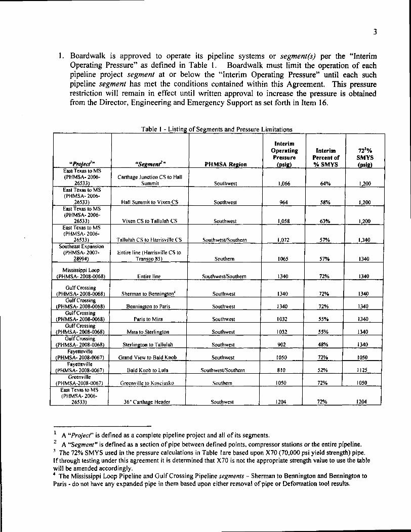
3
1 Boardwalk is approved to operate its pipeline systems or segment(s) per the Interim Operating Pressure as defined in Table 1 Boardwalk must limit the operation of each pipeline project segment at or below the Interim Operating Pressure until each such pipeline segment has met the conditions contained within this Agreement This pressure restriction will remain in effect until written approval to increase the pressure is obtained from the Director Engineering and Emergency Support as set forth in Item 16
T bl I L a e - Istmg 0 fSegments andPressure LImitations
Interim Operating Interim 720 Pressure Percent of SMYS
Project Segmenr PHMSA Re2ion (psiS) SMYS (psg) East Texas to MS (PHMSA- 2006shy Carthage Junction CS to Hall
26533) Summit Southwest 1066 64 1200 East Texas to MS (PHMSA- 2006shy
26533) Hall Summit to Vixen CS Southwest 964 58 1200 East Texas to MS (PHMSA- 2006shy
26533) Vixen CS to Tallulah CS Southwest 1058 63 1200 East Texas to MS (pHMSA- 2006shy
26533) Tallulah CS to Harrisville CS SouthwestSouthern 1072 57 1340 Southeast Expansion
(PHMSA- 2007shy Entire line (Harrisville CS to 28994) Transco 85) Southern 1065 57 1340
Mississippi Loop JPHMSA- 2008-0068) Entire line SouthwestSouthern 1340 72 1340
Gulf Crossing JPHMSA- 2008-0068) Sherman to Bennington Southwest 1340 72 1340
Gulf Crossing (PHMSA- 2008-0068) Bennington to Paris Southwest 1340 72 1340
Gulf Crossing (PHMSA- 2008-00681 Paris to Mira Southwest 1032 55 1340
Gulf Crossing JPHMSA- 2008-0068) Mira to Sterlington Southwest 1032 55 1340
Gulf Crossing (PHMSA- 2008-0068) Sterlington to Tallulah Southwest 902 48 1340
Fayetteville (PHMSA- 2008-0067) Grand View to Bald Knob Southwest 1050 72 1050
Fayetteville (PHMSA- 2008-0067) Bald Knob to Lula SouthwestSouthern 810 52 112S
Greenville (PHMSA-2008-0067) Greenville to Kosliusko Southern 1050 72 1050
East Texas to MS (PHMSA- 2006shy
26533) 36 Carthage Header Southwest 1204 72 1204
1 A Project is defined as a complete pipeline project and all of its segments 2 A Segment is defined as a section of pipe between defined points compressor stations or the entire pipeline J The 72 SMYS used in the pressure calculations in Table I are based upon X70 (70000 psi yield strength) pipe If through testing under this agreement it is determined that X70 is not the appropriate strength value to use the table will be amended accordingly 4 The Mississippi Loop Pipeline and Gulf Crossing Pipeline segments - Sherman to Bennington and Bennington to Paris - do not have any expanded pipe in them based upon either removal of pipe or Defonnation tool results
4
Actions that must be taken prior to increasing the pressure above the Interim Operating Pressure up to 72 SMYS
2 Prior to being allowed to operate any pipeline segment up to 72 specified minimum yield strength (SMYS) (as defined in Table 1) Boardwalk must evaluate that pipeline segment with a high resolution defonnation tool specifically for identifying potentially expanded pipe Once the pipeline defonnation tool results from the Fayetteville and Greenville Lateral Pipelines5 become available and are evaluated which is anticipated to occur during the summer of 2009 Boardwalk may elect to submit an alternative plan for remediating the Fayetteville and Greenville Lateral Pipelines In such event PHMSA will review and assess such plan including reviewing the Proposed Interim Operating Pressures identified above
3 Unless otherwise agreed to in writing by PHMSA or as set forth herein Boardwalk must cut out all expanded pipe over API 5L tolerances on expansion 025 or 060 of diameter for 42-inch pipe and 027-inch or 075 of diameter fot 36-inch pipe After cutting out the expanded pipe in any given segment Boardwalk may request to operate that segment up to 72 percent SMYS Boardwalk must submit requests to modify this agreement or to increase operating pressures in accordance with Item 16 below
4 Boardwalk must submit a Construction Plan to the Director Engineering and Emergency Support with copies to the Directors PHMSA Southern and Southwestern Regions The plan should contain any planned deformation tool runs and updated with the schedules for removal of any identified expanded pipe For purposes of this Agreement a Construction Plan shall mean the weekly reports that Boardwalk currently submits that outlines the work anticipated to occur during the following week Boardwalk is to submit these Construction Plans each week
5 The Construction Plan referenced in Item 4 must address the removal of the pipe joints containing the three horizontal directional drill anomalies identified on the 42-inch East Texas to Mississippi Pipeline6 that appear to have expansion of approximately 10 to 225 five horizontal directional drill (HOD) anomalies on the 42-inch Southeast Expansion Pipeline7 that appear to have an expansion of approximately 10 and one horizontal directional drill anomaly on the Gulf Crossing PipelineS that may have an expansion of approximately 10
s The 36 Fayetteville Lateral deformation tool run is scheduled for May 28 on the 66 mile section from Grandview to Bald Knob AR The 36 Greenville Lateral deformation tool run is scheduled for June 2 on the 97 mile section from Greenville to Kosciusko MS The 36 Carthage Header (part of the East Texas to Mississippi Pipeline Project) defonnation tool run is scheduled for the week of May 4 for the entire 3 mile segment 6 The 42-inch East Texas to Mississippi Pipeline Hall Summit to Vixen segment has the following anomalies in HDDs a) Saline Bayou West - 2 anomalies b) Saline Bayou East - I anomaly c) Dugdemona Creek - I anomaly 7 The 42-inch Southeast Expansion Pipeline has the following anomalies in HDDs a) Campbell Creek - I anomaly b) Leaf River - I anomaly c) West Tallahalla Creek - I anomaly d) Tallahalla Creek - I anomaly and e) County Road 613 - I anomaly 8 The 42-inch Gulf Crossing Pipeline Mira to Sterlington segment has the following anomaly in a HDD a) Dorcheat Bayou - I anomaly
5
6 If any pipe that has been identified as Expanded (as defined in Item 3) is not removed including any of the joints identified in Item 5 Boardwalk must submit to the Director Engineering and Emergency Support with copies to the Directors PHMSA Southern and Southwestern Regions a technical justification why the expanded pipe can be operated safely at the higher operating pressures
Actions that must be taken prior to increasing the pressure above the 72 SMYS up to MAOP Special Permit Conditions
7 Boardwalk must continue with testing of pipe removed from the subject segments in order to establish the serviceability up to 80 SMYS operating parameters For each 42-inch and 36shyinch pipe steel supplier rolling campaign and slab source with an identified pipe expansion a) A minimum of 4 pipe joints must be tested showing no expansion after hydrotest9
b) A minimum of 4 pipe joints must be tested showing expansion between 06 of diameter lO (075 of diameter for the 36 pipe) to 10 expansion after hydrotest
c) A minimum of 4 pipe joints must be tested showing expansion betweengt 10 to 20 expansion hydrotest
d) All pipe joints must be tested showing expansion greater than 20 expansion after hydrotest
e) A minimum of 4 pipe joints must be tested that have not previously been hydrotested f) If less than 4 pipe joints exists for a category listed above only those meeting criteria that
are removed will be tested g) The total test pipe joints for non-expanded pipe in Items 7 (a) and (e) must total at least
10 of the removed expanded pipe joints for each such category ie pipe supplier rolling campaign and slab source
A metallurgical examination must be conducted including mechanical (yield tensile hardness elongation charpy impact and if necessarydrop weight tear test- DWIT) chemical composition and cross-sectional and grain size Test coupons (transverse) must be taken from 2 distant locations down the pipe joint for each metallurgical test item listed above and opposite the pipe seam This testing must include full destructive testing as set forth in API 5L
8 Boardwalk must continue to test pipe cut out from the pipeline segments as set forth above to determine a Technical Fitness for Purpose Repair and Operating Plan This Technical Fitness for Purpose Repair and Operating Plan must be submitted to PHMSA within 180 days of operating each pipeline up to 72 SMYS Until this plan is accepted Boardwalk must limit operation of each pipeline segment at a pressure of at or below 72 SMYS Boardwalk must submit requests to modify this Agreement or to increase operating pressures in accordance with Item 16 below
9 Boardwalk must incorporate Items 10 II and 12 below into their 0 amp M Plan or Construction Plan as applicable for each such segment
9 The hydrotest parameters are specified in the Special Permit 10 06 equals 025 for 42 pipe
6
10 Boardwalk must run close interval surveys (CIS) and remediate the pipe in each segment in accordance with 49 CFR Part 192 on a periodic basis not to exceed 45 months
II Boardwalk must run ILl Tools to evaluate for metal loss anomalies within 18 months of removing expanded pipe from each pipeline Project or segment
12 Boardwalk must evaluatell all metal loss anomalies found on these pipeline segments in accordance with the following criteria until the Technical Fitness for Purpose Repair and Operating Plan is implemented All anomaly evaluations and repairs for the 72 SMYS operations in the special pennit segment regardless of HCA status must be performed based upon the following
a) Anomaly Response Time Immediately bull Any anomaly within a segment operating up to 72 SMYS with either (1) a failure
pressure ratio (FPR) equal to or less than 125 (2) an anomaly depth equal to or greater than 50 wall thickness loss
bull Any anomaly within a segment operating up to 60 SMYS with either (1) an FPR equal to or less than 140 (2) an anomaly depth equal to or greater than 50 wall thickness loss
bull Any anomaly within a segment operating up to 50 SMYS with either (1) an FPR equal to or less than 15 (2) an anomaly depth equal to or greater than 50 wall thickness loss
b) Anomaly Response Time Repair Within One Year bull Any anomaly within a segment operating at up to 72 SMYS with either (I) an
FPR equal to or less than 139 (2) an anomaly depth equal to or greater than 40 wall thickness loss
bull Any anomaly within a segment operating at up to 60 SMYS with either (1) an FPR equal to or less than 167 (2) an anomaly depth equal to or greater than 40 wall thickness loss
bull Any anomaly within a segment operating at up 50 SMYS with either (1) an FPR equal to or less than 20 (2) an anomaly depth equal to or greater than 40 wall thickness loss
c) Anomaly Response Time Monitored Conditions bull Anomalies not requiring immediate or one year repairs above must be reassessed
according to 49 CFR Part 192 SUbpart 0 reassessment intervals bull Each anomaly not repaired under the immediate repair requirements must have a
corrosion growth rate and ILl tool tolerance assigned per Boardwalks Gas Integrity Management Program (IMP) to determine the maximum re-inspection interval
d) Anomaly Assessment Methods bull Boardwalk must confirm the remaining strength (R-STRENG) effective area
method R-STRENG - 085dL and ASME 831G assessment methods are valid for the pipe diameter wall thickness grade operating pressure operating stress level and operating temperature Boardwalk must use the most conservative method until
1 Evaluate means to review III data excavate indication evaluate (measure) actual anomaly and take appropriate repair actions
7
confirmation of the proper method is made to the Director Engineering and Emergency Support with copies to the Directors PHMSA Southern and Southwestern Regions
13 Boardwalk must complete the 36middotinch Fayetteville Lateral Pipeline Project girth weld inspection and remediation plan as outlined below prior to operating the applicable segments above 72 SMYS as documented in Table 1
Fayetteville Lateral Project Girth Weld Inspection and Remediation Protocol
Phase I - Program Development
1 Boardwalk must review the welding weld repair and nondestructive testing (NDT) procedures that were used for the repair of the girth weld that failed during hydrostatic testing to ensure there are no technical problems with the procedures
2 Boardwalk must review the Fayetteville Lateral Project construction records to identify locate and catalog all girth weld repairs completed with the same procedures used on the failed girth weld
3 Boardwalk must review the Fayetteville Lateral Project specifications and construction records regarding the actual placement of supports underneath the pipe at tiemiddotins overmiddotbends sag-bends and other areas of high stress to ensure that high stresses are not occurring on the Fayetteville Lateral Project as a result of inadequate pipe support
4 The girth weld inspection and remediation program must include the nondestructive testing (NOT) and repair (if necessary) of girth welds along the Fayetteville Lateral Project with special emphasis on those areas of the pipeline subjected to the highest external loading Boardwalk must identify investigate and where necessary remediate previously repaired girth welds that meet the following criteria
a) On any previously repaired girth weld where welding andlor NDT procedures may not have been properly followed b) On any repaired girth welds in the vicinity of the failed girth weld with a minimum remiddotinspection of three repaired girth welds upstream and three downstream of the failed girth weld c) On any repaired girth welds in agricultural areas where heavy farm equipment may add to overburden stresses d) On any repaired girth welds on the top and bottom of the pipe and e) On any repaired girth welds near overmiddot bends or sag-bends
5 Boardwalk must submit the findings of the Fayetteville Lateral Project Girth Weld Inspection and Remediation Protocol Items 1 2 and 3 above and the
8
framework of the girth weld inspection and remediation program (Item 4) to the Director Engineering and Emergency Support with copies to the Directors PHMSA Southern and Southwestern Regions for review prior to beginning any excavations
Phase II - Program Implementation
1 Boardwalk must implement the program as described above
2 If problems are discovered after the girth weld inspection and remediation program is implemented Boardwalk must also address each of the following as required
(a) Repair girth welds on hilltops
(b) Repair girth welds where hi-Io pipe alignment issues were not resolved by shims (c) Repair girth welds at excessive depth locations (d) Repair girth welds in the downstream section of compressor stations and (e) Repair girth welds in other areas determined to be of high risk from excessive external forces such as bored crossings of highwaysrailroads and at valve settings
3 Boardwalk must submit all the findings and results of the girth weld inspection and remediation program to the Director Engineering and Emergency Support with copies to the Directors PHMSA Southern and Southwestern Regions for review
14 Should Boardwalk find through the deformation tool evaluations and excavations of the identified anomalies or develop any additional information whether through the investigation or testing described otherwise herein that may technically warrant a modification of any of the provisions of this agreement Boardwalk may notify the Director Engineering and Emergency Support with copies to the Directors Southern and Southwestern Regions of these findings and request approval of the proposed modifications
1S Boardwalk is to submit quarterly reports to the Director Engineering and Emergency Support with copies to the Directors Southern and Southwestern Regions that (I) include available data and results of the testing and evaluations required by this Agreement and (2) describe the progress of the repairs and other remedial actions being undertaken The first quarterly report shall be due June 1 2009
16 The Director may allow the removal or modification of the pressure restriction set forth in the Agreement upon a written request from Boardwalk demonstrating that the potentially low yield strength risk has been abated and that restoring the affected pipeline or portion thereof to its otherwise applicable MAOP is justified based on a reliable engineering analysis or other mutually agreeable data including industry publications or studies showing that the pressure increase is safe considering all known physical properties and operating parameters of the pipeline
9
III Relationship to Original MAOP Special Permits
The additional conditions set forth in this Agreement are in addition to the conditions in the original special permits and Boardwalk must comply with both the original special permit terms and this Agreement To the extent a term or condition in the original special permit and this Agreement are in conflict the condition in this Agreement is controlling
IV Review and Approval Process
All submissions required or allowed under this Agreement should be submitted electronically in the absence of good cause to do otherwise With respect to each submission that under this Agreement requires the approval of the Director Engineering and Emergency Support the Director may (a) approve in whole or in part the submission (b) approve the submission on specified conditions (c) disapprove in whole or in part the submission or (d) any combination of the foregoing In the event of approval approval in part or approval with conditions Boardwalk will proceed to take all action required by the submission as approved by the Director In the event that the Director disapproves all or any portion of the submission the Director will provide Boardwalk with prompt written notice of the deficiencies and the specific additional action needed to obtain approval Boardwalk will correct all deficiencies within the reasonable time specified by the Director and resubmit it for approval
V Enforcement
This Agreement is incorporated into the special permits issued by PHMSA for the specified pipelines and is subject to all enforcement authorities available to PHMSA under 49 USC sect 60101 et seq and 49 CFR Part 190 including administrative civil penalties under sect 60122 of up to $100000 per violation for each day the violation continues if PHMSA determines that Boardwalk is not proceeding in accordance with terms of the agreement determinations made by the Regional Director or if appealed decisions of the Associate Administrator Any work plans and associated schedules shall be automatically incorporated into this Agreement and are enforceable in the same manner Notwithstanding anything herein Boardwalk shall have all of its legal rights to challenge appeal or otherwise contest any proposed enforcement authority asserted for alleged non-compliance with this Agreement
VI Modification
The terms of this Agreement may be modified by mutual agreement of the parties Such modifications shall be in writing and shall be signed by both parties
VII Termination
This Agreement shall terminate upon the completion of all terms set forth in Section II (Additional Special Permit Conditions) Boardwalk may request written confirmation from PHMSA when this Agreement is terminated To the extent ongoing monitoring is required
10
PHMSA may terminate this Agreement with respect to all other requirements with the exception of such monitoring Nothing in this Agreement prevents Boardwalk from completing any of the obligations earlier than the deadlines provided for herein
VIII Ratification
The parties undersigned representatives certify that they are fully authorized to enter into the terms and conditions of this Agreement and to execute and legally bind such party to this document
On behalf of Boardwalk I hereby agree to all conditions and terms of this Agreement and agree to implement this Agreement on the referenced pipeline projects and segments
Walter Bennett Date Senior Vice President of Operations Boardwalk Pipeline Partners LP
~Ihte DateY40JJeffrey D Wiese Associate Administrator for Pipeline Safety
1
US DEPARTMENT OF TRANSPORTATION
PIPELINE AND HAZARDOUS MATERIALS SAFETY ADMINISTRATION (PHMSA)
SPECIAL PERMIT
Docket Number PHMSA-200S-006S
Requested By Gulf Crossing Pipeline Company LLC and Gulf South Pipeline Company LP
[subsidiaries ofBoardwalk Pipeline Partners LP]
Date Requested December 31 2007
Code Sections 49 CFR sectsect 192111 and 192201
Grant of Special Permit
By this order The Pipeline and Hazardous Materials Safety Administration (PHMSA) grants this
special permit to the Gulf Crossing Pipeline Company LLC (GCPC) and Gulf South Pipeline
Company LP (GSPC) [subsidiaries ofBoardwalk Pipeline Partners LP] subject to the
conditions and limitations set forth below The special permit waives compliance from 49 CFR
sect 192111 and sect 192201 for the Gulf Crossing Project (GCP) pipeline a proposed 3532-mile
42-inch diameter natural gas transmission pipeline to be installed and operated by GCPC from
Grayson County Texas to Madison Parish Louisiana The special permit also waives
compliance from 49 CFR sect 192111 and sect 192201 for the Mississippi Loop (ML) a 17S-mile
42-inch diameter natural gas transmission loop pipeline to be installed and operated by GSPC in
Hinds Copiah and Simpson Counties Mississippi
This special permit allows GCPC to design construct and operate the GCP pipeline and the
GSPC to design construct and operate the ML pipeline in Class 1 locations using a design factor
in sect 192111 up to OSO and at stress levels up to SO ofthe specified minimum yield strength
(SMYS) in Class 2 locations using a design factor in sect 192111 up to 067 and at stress levels up
to 67 of SMYS and in Class 3 locations using a design factor in sect 192111 up to 056 and at
stress levels up to 56 of SMYS This would result in maximum allowable operating pressures
(MAOP) of 14S0 pounds per square inch gauge (PSIG)
This special permit also allows GCPC to design install and operate pressure relief and limiting
devices on the GCP pipeline and the GSPC to design install and operate pressure relief and
2
limiting devices on the ML pipeline with a capacity that would ensure the pressure in Class 1
Class 2 and Class 3 location pipeline segments would not exceed 104 ofthe MAOP or the
pressure that produces a hoop stress of 832 SMYS in Class 1 locations 697 SMYS in Class
2 locations or 582 SMYS in Class 3 locations during an overpressure event
For the purpose of this special permit the special permit area means the area consisting of the
entire pipeline right-of-way for those segments of the GCP and ML pipelines that will operate
above 72 SMYS in Class 1 locations above 60 SMYS in Class 2 locations above 50
SMYS in Class 3 locations
PHMSA grants this special permit based on the findings set forth in the Special Permit Analysis
and Findings document which can be read in its entirety in Docket No PHMSA-2008-0068 in
the Federal Docket Management System (FDMS) located on the Internet at
www Regul ationsgov
Conditions
This special permit is granted subject to the following conditions
1) Steel Properties The skelpplate must be micro alloyed fine grain fully killed steel with
calcium treatment and continuous casting
2) Manufacturing Standards The pipe must be manufactured according to American
Petroleum Institute Specification 5L Specification for Line Pipe (API 5L) product
specification level 2 (PSL 2) supplementary requirements (SR) for maximum operating
pressures and minimum operating temperatures Pipe carbon equivalents must be at or
below 023 based on the material chemistry parameter (Pcm) formula
3) Fracture Control API 5L the American Society ofMechanical Engineers B318 Standard
(ASME B318) and other specifications and standards address the steel pipe toughness
properties needed to resist crack initiation crack propagation and to ensure crack arrest
during a pipeline failure caused by a fracture GCPC and GSPC must institute an overall
fracture control plan addressing steel pipe properties necessary to resist crack initiation and
crack propagation and to arrest a fracture within 8 pipe joints with a 99 occurrence
probability or within 5 pipe joints with a 90 occurrence probability The plan must
include acceptable Charpy Impact and Drop Weight Tear Test values which are measures
3
include acceptable Charpy Impact and Drop Weight Tear Test values which are measures
of a steel pipelines toughness and resistance to fracture The fracture control plan which
must be submitted to PHMSA headquarters must be in accordance with API 5L Appendix
F and must include the following tests
a) SR 5A - Fracture Toughness Testing for Shear Area Test results must indicate at least
85 minimum average shear area for all X- 70 heats and 80 minimum shear area for
all X- 80 heats with a minimum result of 80 shear area for any single test The test
results must also ensure a ductile fracture and arrest
b) SR 5B - Fracture Toughness Testing for Absorbed Energy and
c) SR 6 - Fracture Toughness Testing by Drop Weight Tear Test Test results must be at
least 80 of the average shear area for all heats with a minimum result of 60 of the
shear area for any single test The test results must also ensure a ductile fracture and
arrest
The above fracture initiation propagation and arrest plan must account for the entire range
of pipeline operating temperatures pressures and gas compositions planned for the pipeline
diameter grade and operating stress levels including maximum pressures and minimum
temperatures for shut-in conditions associated with the special pennit area Where the use
of stress factors pipe grade operating temperatures and gas composition make fracture
toughness calculations non-conservative correction factors must be used If the fracture
control plan for the pipe in the special pennit area does not meet these specifications
GCPC and GSPC must submit to PHMSA headquarters an alternative plan providing an
acceptable method to resist crack initiation crack propagation and to arrest ductile fractures
in the special pennit area
4) Steel Plate Quality Control The steel mill andor pipe rolling mill must incorporate a
comprehensive platecoil mill and pipe mill inspection program to check for defects and
inclusions that could affect the pipe quality This program must include a plate or rolled
pipe ultrasonic testing (UT) inspection program to check for imperfections such as
laminations UT inspection must be conducted on all factory beveled pipe ends In
addition pipe body UT inspection must be conducted on a minimum of 100 of pipe joints
and all ends with a minimum coverage of 35 of the pipe body for those joints inspected
Any laminations identified by the UT inspection program must be evaluated in accordance
4
with the acceptance criteria defined in ASTM International Standard ASTM A5781A578M
Standard Specification for Straight-Beam Ultrasonic Examination ofRolled Steel Plates
for Special Applications (ASTM A578) Level B or API 5L Paragraph 7810 An
inspection protocol for centerline segregation evaluation using a test method referred to as
slab macro-etching must be employed to check for inclusions that may form as the steel
plate cools after it has been cast A minimum of one macro-etch or a suitable alternative
test must be performed from the first or second heat (manufacturing run) of each sequence
(approximately 4 heats) and graded on the Mannesmann scale or equivalent Test results
with a Mannesmann scale rating of one or two out of a possible four or five scale are
acceptable
5) Pipe Seam Quality Control A quality assurance program must be instituted for pipe weld
seams The pipe weld seam tests must meet the minimum requirements for tensile strength
in API 5L for the appropriate pipe grade properties A pipe weld seam hardness test using
the Vickers hardness testing of a cross-section from the weld seam must be performed on
one length of pipe from each heat The maximum weld seam and heat affected zone
hardness must be a maximum of 280 Vickers hardness (HvlO) The hardness tests must
include a minimum of 3 readings for each heat affected zone 3 readings in the weld metal
and 2 readings in each section of pipe base metal for a total of 13 readings The pipe weld
seam must be 100 UT inspected after expansion and hydrostatic testing per API 5L
6) Mill Hydrostatic Test The pipe must be subjected to a mill hydrostatic test to achieve a
minimum stress level of 95 SMYS in the pipe for a minimum duration of 10 seconds
The 95 stress level may be achieved using a combination of internal test pressure and the
application of end loads imposed by the hydrostatic testing equipment as allowed by API
5L Appendix K
7) Pipe Coating The application of a corrosion resistant coating to the steel pipe must be
subject to a coating application quality control program The program must address pipe
surface cleanliness standards blast cleaning application temperature control adhesion
cathodic disbondment moisture permeation bending minimum coating thickness coating
imperfections and coating repair
8) Field Coating A field girth weld joint coating application specification and quality
standards to ensure pipe surface cleanliness application temperature control adhesion
5
quality cathodic disbondment moisture permeation bending minimum coating thickness
holiday detection and repair quality must be implemented in field conditions Field joint
coatings must be non-shielding to cathodic protection (CP) Field coating applicators must
use valid coating procedures and be trained to use these procedures
9) Coatings for Trenchless Installation Coatings used for directional bore slick bore and
other trenchless installation methods must resist abrasions and other damages that may
occur due to rocks and other obstructions encountered in this installation technique
10) Bends Quality Certification records of factory induction bends andor factory weld bends
must be obtained and retained All bends flanges and fittings must have carbon
equivalents (CE) below 042 or a pre-heat procedure must be applied prior to welding for
CE above 042
11) Fittings All pressure rated fittings and components (including flanges valves gaskets
pressure vessels and compressors) must be rated for a pressure rating commensurate with
the MAOP and class location of the pipelines Designed fittings (including tees elbows
and caps) must have the same design factor as the adjacent pipe
12) Design Factor - Pipelines Pipe installed under this special permit in Class 1 locations may
use a design factor of 080 in Class 2 locations may use a design factor of 067 and in
Class 3 locations may use a design factor of 056
13) Temperature Control The compressor station discharge temperature must be limited to
120deg Fahrenheit A temperature above this maximum temperature of 120deg Fahrenheit may
be approved if GCPC and GSPC technical coating operating tests show that the pipe
coating will properly withstand the higher operating temperature for long term operations
If the temperature exceeds 120deg Fahrenheit GCPC and GSPC must also institute a coating
monitoring program in these areas using ongoing Direct Current Voltage Gradient (DCVG)
surveys or Alternating Current Voltage Gradient (ACVG) surveys or other testing to
demonstrate the integrity of the coating This program and results must be provided to the
regional offices of PHMSA where the pipe is in service
14) Overpressure Protection Control Mainline pipeline overpressure protection must be
limited to a maximum of 104 MAOP
15) Welding Procedures For automatic or mechanized welding the 19th Edition of API 1104
Welding of Pipelines and Related Facilities will be used for welding procedure
6
qualification welder qualification and weld acceptance criteria Operator must use the
19th Edition of API 1104 for all other welding processes The appropriate PHMSA
regional office must be notified within 14 days of the beginning of welding procedure
qualification activities Automated or manual welding procedure documentation must be
submitted to the same PHMSA regional office
16) Depth of Cover The soil cover must be a minimum depth of 36 inches in all areas In
areas where threats from chisel plowing or other activities are threats to the pipelines the
top of the pipelines must be installed at least one foot below the deepest penetration above
the pipelines If routine patrols or other observed conditions indicate the possible loss of
cover over the pipelines GCPC and GSPC will perform a depth of cover study and replace
cover as necessary to meet the minimum depth of cover requirements specified herein
17) Construction Quality A construction quality assurance plan to ensure quality standards
and controls must be maintained throughout the construction phase with respect to
inspection pipe hauling and stringing field bending welding non-destructive examination
(NDE) of girth welds field joint coating pipeline coating integrity tests lowering of the
pipeline in the ditch padding materials to protect the pipeline backfilling alternating
current (AC) interference mitigation and CP systems All girth welds must be nonshy
destructively examined by radiography or alternative means The NDE examiner must
have all required and current certifications
18) Interference Currents Control Control of induced AC from parallel electric transmission
lines and other interference issues that may affect the pipelines must be incorporated into
the design of the pipelines and addressed during the construction phase Issues identified
and not originally addressed in the design phase must be brought to PHMSAs attention by
notifying the appropriate regional office An induced AC program to protect the pipelines
from corrosion caused by stray currents must be in place within six months after placing
the pipelines in service
19) Test Level The pre-in service hydrostatic test must be to a pressure producing a hoop
stress of at least 100 SMYS and 125 X MAOP in areas to operate up to 80 SMYS and
at least 150 X MAOP in areas to operate to 67 SMYS and 56 SMYS Short segments
of pipe (up to one mile in length) having a design factor between 72 SMYS and less than
80 SMYS may be tested with 80 SMYS pipe provided the test pressure produces a
7
hoop stress of at least 125 X MAOP for all pipe tested
20) Assessment of Test Failures Any pipe failure occurring during the pre-in service
hydrostatic test must undergo a root cause failure analysis to include a metallurgical
examination of the failed pipe The results of this examination must preclude a systemic
pipeline material issue and the results must be reported to PHMSA headquarters and the
appropriate PHMSA regional office
21) Supervisory Control and Data Acquisition (SCADA) System Capabilities A SCADA
system to provide remote monitoring and control of the pipeline system must be employed
22) SCADA Procedures A detailed procedure for establishing and maintaining accurate
SCADA set points must be established to ensure the pipelines operate within acceptable
design limits at all times
23) Mainline Valve Control Mainline valves located on either side of a pipeline segment
containing a High Consequence Area (HCA) where personnel response time to the valve
exceeds one hour must be remotely controlled via the SCADA system The SCADA
system must be capable of closing these mainline valves and monitoring the valve position
as well as upstream pressure and downstream pressure at the mainline valve As an
alternative a leak detection system for mainline valve control is acceptable
24) Pipeline Inspection The pipelines must be capable of passing in-line inspection (ILl)
tools All headers and other segments covered under this special permit that do not allow
the passage of an ILl device must have a corrosion mitigation plan
25) Gas Quality Monitoring An acceptable gas quality monitoring and mitigation program
must be instituted to not exceed the following limits
a) H2S (10 grain per 100 standard cubic feet or 16 parts per million (ppm) maximum)
b) CO2 (3 maximum)
c) H20 (less than or equal to 7 pounds per million standard cubic feet and no free water)
and
d) Other deleterious constituents that may impact the integrity of the pipelines
26) The pipelines must have an ongoing pigging and liquids sampling plan to identify mitigate
and remove deleterious constituents where applicable
27) If H2S is above 8 parts ppm the gas stream constituents must be reviewed for
implementation of a quarterly pigginginhibitor injection program including follow up
8
sampling of liquids at receipt points
28) Gas Quality Control Separators or Filtersseparators must be installed at locations where
gas is received into the pipelines where the incoming gas stream quality includes
potentially deleterious free liquids andor particulates to minimize the entry of
contaminants and to protect the integrity of downstream pipeline segments
29) Gas Quality Monitoring Equipment Equipment including moisture analyzer
chromatograph and semi-annual H2S sampling (quarterly sampling where H2S is above 8
ppm) must be installed to permit the operator to manage and limit the introduction of
contaminants and free liquids into the pipelines
30) Cathodic Protection The initial CP system must be operational within 12 months of
placing any pipeline segment in service
31) Interference Current Surveys Interference surveys must be performed within six months
of placing the pipeline in service to ensure compliance with applicable NACE International
Standard Recommended Practices 0169 and 0177 (NACE RP 0169 and NACE RP 0177)
for interference current levels If interference currents are found GCPC and GSPC will
determine if there have been any adverse affects to the pipeline and mitigate the affects as
necessary GCPC and GSPC will report the results of any negative finding and the
associated mitigative efforts to the appropriate PHMSA regional office
32) Corrosion Surveys Corrosion surveys of the affected pipelines must be completed within
six months of placing the respective CP system(s) in operation to ensure adequate external
corrosion protection per NACE RP 0169 The survey will also address the proper number
and location of CP test stations as well as AC interference mitigation and AC grounding
programs per NACE RP 0177
33) Verification of Cathodic Protection An intemlpted close interval survey (CIS) must be
performed in concert and integrated with ILl in accordance with 49 CFR 192 Part Subpart
o reassessment intervals for all HCA pipeline mileage At least one CP test station must be
located within each HCA with a maximum spacing between test stations of one-half mile
within an HCA If any annual test station reading fails to meet 49 CFR 192 Part Subpart I
requirements remedial actions must occur within six months Remedial actions must
include a CIS on each side of the affected test station and all modifications to the CP
system necessary to ensure adequate external corrosion control
9
34) Initial Close Interval Survey (CIS) - Initial A CIS must be performed on the pipelines
within two years of the pipeline in-service dates The CIS results must be integrated with
the baseline ILl to determine whether further action is needed
35) Initial Coating Assessment - GCPC and GSPC must assess the integrity of the pipelines
coating after completion of padding and backfill during constmction through use of coating
indirect assessment methods such as DCVG or ACVG surveys or equivalent methods
GCPC and GSPC must remediate any damaged coating found during these assessments
that are classified as minor and at or above 15 IR for DCVG or at or above 30 dBlV
ACVG moderate or severe based on NACE International Recommended Practice 0502shy
2002 Pipeline External Corrosion Direct Assessment Methodology (NACE RP 0502shy
2002) A minimum of two coating survey assessment classifications must be excavated
classified andor remediated per each survey crew and compressor station discharge
pipeline section to verify survey results
36) Pipeline Markers GCPC and GSPC must employ line-of-sight markings on the pipelines
in the special permit area except in agricultural areas or large water crossings such as lakes
where line-of-sight markers are not practical The marking of pipelines is also subject to
Federal Energy Regulatory Commission orders or environmental permits and local
restrictions
37) Pipeline Patrolling Pipeline patrolling must be conducted at least monthly (12 times per
calendar year) not to exceed 45 days to inspect for excavation activities ground
movement wash-outs leakage or other activities and conditions affecting the safe
operation of the pipelines
38) Monitoring of Ground Movement An effective monitoringmitigation plan must be in
place to monitor for and mitigate issues of unstable soil and ground movement
39) Initial ILl GCPC and GSPC must perform a baseline ILl in association with the
constmction of the pipelines using a high-resolution Magnetic Flux Leakage (MFL) tool to
be completed within three years of placing a pipeline segment in service GCPC and GSPC
must perform a baseline geometry tool mn after completion of the hydrostatic strength test
and backfill of the pipelines (just prior to placing the pipelines in service) but no later than
six months after placing the pipelines in service in accordance with the conditions allowed
by the special permit
10
40) Future ILl A second high-resolution MFL inspection must be performed and completed
on the pipe subject to this special permit within the first reassessment interval required by
49 CFR Part 192 Subpart 0 regardless of HCA classification Future ILl must be
performed on a frequency consistent with Subpart degfor the entire pipelines covered by this
special permit
41) Direct Assessment Plan Headers mainline valve bypasses and other sections in the
special pennit area that cannot accommodate ILl tools must be part of a Direct Assessment
(DA) plan or other acceptable integrity monitoring method using External and Internal
Corrosion Direct Assessment criteria (ECDAlICDA)
42) Damage Prevention Program The Common Ground Alliances (CGA) damage prevention
best practices applicable to pipelines must be incorporated into the GCPC and GSPC
damage prevention program
43) Anomaly Evaluation and Repair Anomaly evaluations and repairs in the special penni
area regardless of HCA status must be performed based upon the following
a) Anomaly Response Time Repair Immediately
- Any anomaly within a special penni area operating up to SO SMYS with a
failure pressure ratio (FPR) equal to or less than 11 andor an anomaly depth equal
to or greater than SO wall thickness loss
- Any anomaly within a special permit area operating up to 67 SMYS with an FPR
equal to or less than 125 andor an anomaly depth equal to or greater than SO wall
thickness loss
- Any anomaly within a special permit area operating up to 56 SMYS with an FPR
equal to or less than 14 andor an anomaly depth equal to or greater than SO wall
thickness loss
b) Anomaly Response Time Repair Within One Year
- Any anomaly within a special pennit area operating at up to SO SMYS with a
FPR equal to or less than 125
- Any anomaly within a special pennit area operating at up to 67 SMYS with a
FPR equal to or less than 15
- Any anomaly within a special pennit area operating at up 56 SMYS with an FPR
equal to or less than 1S
11
c) Anomaly Response Time Monitored Conditions
- Anomalies not requiring immediate or one year repairs per paragraphs a and b
above must be reassessed according to 49 CFR Part 192 Subpart 0 reassessment
intervals
- Each anomaly not repaired under the immediate repair requirements must have a
corrosion growth rate and ILl tool tolerance assigned per the Gas Integrity
Management Program (IMP) to determine the maximum re-inspection interval
d) Anomaly Assessment Methods
- GCPC and GSPC must confirm the remaining strength (R-STRENG) effective area
method 085dL and ASME B31 G assessment methods are valid for the pipe
diameter wall
- Thickness grade operating pressure operating stress level and operating
temperature GCPC and GSPC must also use the most conservative method until
confirmation of the proper method is made to PHMSA Headquarters
- Dents in the pipe in the special permit area must be evaluated and repaired per
49 CFR sect 192309(b) for the baseline geometry tool run and per 49 CFR
sect 192933(d) for future ILl
44) Potential Impact Radius Calculation Updates If the pipeline operating pressures and gas
quality are determined to be outside the parameters of the C-FER Study a revised study
with the updated parameters must be incorporated into the IMP
45) Reporting - Immediate GCPC and GSPC must notify the appropriate PHMSA regional
office within 24 hours of any non-reportable leaks occurring in the special permit area
46) Reporting - 30 Day At least thirty (30) days prior to the pipeline in- service date under
this special permit Operator shall report on its compliance with special permit conditions
to PHMSA headquarters and the appropriate regional offices
a) Special Permit Conditions 1 through 25 28 29 33 35 3644 and 46 must be
completed and implemented with documentation available for PHMSA review prior to
operating at the special permit MAOP
b) Special Permit Conditions 3 7 through 14 16 18 and 21 through 47 must be included
in the operators written operating and maintenance (OampM) procedures manual
12
concerning permit condition requirements with documentation available for PHMSA
review prior to operating at the special permit MAOP
47) Annual Reporting GCPC and GSPC must report the following to the appropriate PHMSA
regional offices annuallyl
a) The results of any ILl or direct assessment results performed within the special permit
area during the previous year
b) Any new integrity threats identified within the special pennit area during the previous
year
c) The number of new residences other structures intended for human occupancy and
public gathering areas built within the special pennit area
d) Any class or HCA changes in the special pennit area during the previous year
e) Any reportable incidents associated with the special permit area that occurred during
the previous year
f) Any leaks on the pipelines in the special pennit area that occurred during the previous
year
g) A list of all repairs on the pipelines in the special pennit area made during the previous
year
h) On-going damage prevention initiatives on the pipelines in the special pennit area and
a discussion of their success or failure
i) Any changes in procedures used to assess andor monitor the pipelines operating under
this special permit and
j) Any company mergers acquisitions transfers of assets or other events affecting the
regulatory responsibility of the company operating the pipelines to which this special
permit applies
Limitations
PHMSA grants this special permit subject to the following limitations
1) PHMSA has the sole authority to make all determinations on whether GCPC andor GSPC
have complied with the specified conditions of this special permit
I Annual reports must be received by PHMSA by the last day of the month in which the Special Permit is dated For example the annual report for a Special Permit dated March 4 2008 must be received by PHMSA no later than March 31 st each year beginning in 2009
F
13
2) Should GCPC andor GSPC fail to comply with any of the specified conditions of this special
permit PHMSA may revoke this special permit and require GCPC andor GSPC to comply
with the regulatory requirements in 49 CFR sectsect 192111 and 19220l
3) PHMSA may revoke suspend or modify a special permit based on any finding listed in
49 CFR sect 190341(h)(1) and require GCPC andor GSPC to comply with the regulatory
requirements in 49 CFR sectsect 192111 and 19220l
4) Should PHMSA revoke suspend or modify a special permit based on any finding listed in
49 CFR sect 190341(h)(1) PHMSA will notify GCPC andor GSPC in writing of the proposed
action and provide GCPC andor GSPC an opportunity to show cause why the action should
not be taken unless PHMSA determines that taking such action is immediately necessary to
avoid the risk of significant harm to persons property or the environment (see 49 CFR
sect 190341(h)(2raquo
5) The terms and conditions of any corrective action order compliance order or other order
applicable to a pipeline facility covered by this special permit will take precedence over the
terms of this special permit in accordance with 49 CFR sect 190341(h)(4)
AUTHORITY 49 USc 60118(c) and 49 CFR sect 153
d middot W h DC NOV 1 9 2008Issue m as mgton on ________
ttJ2f~ I-I-~ amp~
Jeffrey D Wiese
Associate Administrator for Pipeline Safety
- Bdwlk_Mod_4-30-2009
- Gulf_11-2008
-

4
Actions that must be taken prior to increasing the pressure above the Interim Operating Pressure up to 72 SMYS
2 Prior to being allowed to operate any pipeline segment up to 72 specified minimum yield strength (SMYS) (as defined in Table 1) Boardwalk must evaluate that pipeline segment with a high resolution defonnation tool specifically for identifying potentially expanded pipe Once the pipeline defonnation tool results from the Fayetteville and Greenville Lateral Pipelines5 become available and are evaluated which is anticipated to occur during the summer of 2009 Boardwalk may elect to submit an alternative plan for remediating the Fayetteville and Greenville Lateral Pipelines In such event PHMSA will review and assess such plan including reviewing the Proposed Interim Operating Pressures identified above
3 Unless otherwise agreed to in writing by PHMSA or as set forth herein Boardwalk must cut out all expanded pipe over API 5L tolerances on expansion 025 or 060 of diameter for 42-inch pipe and 027-inch or 075 of diameter fot 36-inch pipe After cutting out the expanded pipe in any given segment Boardwalk may request to operate that segment up to 72 percent SMYS Boardwalk must submit requests to modify this agreement or to increase operating pressures in accordance with Item 16 below
4 Boardwalk must submit a Construction Plan to the Director Engineering and Emergency Support with copies to the Directors PHMSA Southern and Southwestern Regions The plan should contain any planned deformation tool runs and updated with the schedules for removal of any identified expanded pipe For purposes of this Agreement a Construction Plan shall mean the weekly reports that Boardwalk currently submits that outlines the work anticipated to occur during the following week Boardwalk is to submit these Construction Plans each week
5 The Construction Plan referenced in Item 4 must address the removal of the pipe joints containing the three horizontal directional drill anomalies identified on the 42-inch East Texas to Mississippi Pipeline6 that appear to have expansion of approximately 10 to 225 five horizontal directional drill (HOD) anomalies on the 42-inch Southeast Expansion Pipeline7 that appear to have an expansion of approximately 10 and one horizontal directional drill anomaly on the Gulf Crossing PipelineS that may have an expansion of approximately 10
s The 36 Fayetteville Lateral deformation tool run is scheduled for May 28 on the 66 mile section from Grandview to Bald Knob AR The 36 Greenville Lateral deformation tool run is scheduled for June 2 on the 97 mile section from Greenville to Kosciusko MS The 36 Carthage Header (part of the East Texas to Mississippi Pipeline Project) defonnation tool run is scheduled for the week of May 4 for the entire 3 mile segment 6 The 42-inch East Texas to Mississippi Pipeline Hall Summit to Vixen segment has the following anomalies in HDDs a) Saline Bayou West - 2 anomalies b) Saline Bayou East - I anomaly c) Dugdemona Creek - I anomaly 7 The 42-inch Southeast Expansion Pipeline has the following anomalies in HDDs a) Campbell Creek - I anomaly b) Leaf River - I anomaly c) West Tallahalla Creek - I anomaly d) Tallahalla Creek - I anomaly and e) County Road 613 - I anomaly 8 The 42-inch Gulf Crossing Pipeline Mira to Sterlington segment has the following anomaly in a HDD a) Dorcheat Bayou - I anomaly
5
6 If any pipe that has been identified as Expanded (as defined in Item 3) is not removed including any of the joints identified in Item 5 Boardwalk must submit to the Director Engineering and Emergency Support with copies to the Directors PHMSA Southern and Southwestern Regions a technical justification why the expanded pipe can be operated safely at the higher operating pressures
Actions that must be taken prior to increasing the pressure above the 72 SMYS up to MAOP Special Permit Conditions
7 Boardwalk must continue with testing of pipe removed from the subject segments in order to establish the serviceability up to 80 SMYS operating parameters For each 42-inch and 36shyinch pipe steel supplier rolling campaign and slab source with an identified pipe expansion a) A minimum of 4 pipe joints must be tested showing no expansion after hydrotest9
b) A minimum of 4 pipe joints must be tested showing expansion between 06 of diameter lO (075 of diameter for the 36 pipe) to 10 expansion after hydrotest
c) A minimum of 4 pipe joints must be tested showing expansion betweengt 10 to 20 expansion hydrotest
d) All pipe joints must be tested showing expansion greater than 20 expansion after hydrotest
e) A minimum of 4 pipe joints must be tested that have not previously been hydrotested f) If less than 4 pipe joints exists for a category listed above only those meeting criteria that
are removed will be tested g) The total test pipe joints for non-expanded pipe in Items 7 (a) and (e) must total at least
10 of the removed expanded pipe joints for each such category ie pipe supplier rolling campaign and slab source
A metallurgical examination must be conducted including mechanical (yield tensile hardness elongation charpy impact and if necessarydrop weight tear test- DWIT) chemical composition and cross-sectional and grain size Test coupons (transverse) must be taken from 2 distant locations down the pipe joint for each metallurgical test item listed above and opposite the pipe seam This testing must include full destructive testing as set forth in API 5L
8 Boardwalk must continue to test pipe cut out from the pipeline segments as set forth above to determine a Technical Fitness for Purpose Repair and Operating Plan This Technical Fitness for Purpose Repair and Operating Plan must be submitted to PHMSA within 180 days of operating each pipeline up to 72 SMYS Until this plan is accepted Boardwalk must limit operation of each pipeline segment at a pressure of at or below 72 SMYS Boardwalk must submit requests to modify this Agreement or to increase operating pressures in accordance with Item 16 below
9 Boardwalk must incorporate Items 10 II and 12 below into their 0 amp M Plan or Construction Plan as applicable for each such segment
9 The hydrotest parameters are specified in the Special Permit 10 06 equals 025 for 42 pipe
6
10 Boardwalk must run close interval surveys (CIS) and remediate the pipe in each segment in accordance with 49 CFR Part 192 on a periodic basis not to exceed 45 months
II Boardwalk must run ILl Tools to evaluate for metal loss anomalies within 18 months of removing expanded pipe from each pipeline Project or segment
12 Boardwalk must evaluatell all metal loss anomalies found on these pipeline segments in accordance with the following criteria until the Technical Fitness for Purpose Repair and Operating Plan is implemented All anomaly evaluations and repairs for the 72 SMYS operations in the special pennit segment regardless of HCA status must be performed based upon the following
a) Anomaly Response Time Immediately bull Any anomaly within a segment operating up to 72 SMYS with either (1) a failure
pressure ratio (FPR) equal to or less than 125 (2) an anomaly depth equal to or greater than 50 wall thickness loss
bull Any anomaly within a segment operating up to 60 SMYS with either (1) an FPR equal to or less than 140 (2) an anomaly depth equal to or greater than 50 wall thickness loss
bull Any anomaly within a segment operating up to 50 SMYS with either (1) an FPR equal to or less than 15 (2) an anomaly depth equal to or greater than 50 wall thickness loss
b) Anomaly Response Time Repair Within One Year bull Any anomaly within a segment operating at up to 72 SMYS with either (I) an
FPR equal to or less than 139 (2) an anomaly depth equal to or greater than 40 wall thickness loss
bull Any anomaly within a segment operating at up to 60 SMYS with either (1) an FPR equal to or less than 167 (2) an anomaly depth equal to or greater than 40 wall thickness loss
bull Any anomaly within a segment operating at up 50 SMYS with either (1) an FPR equal to or less than 20 (2) an anomaly depth equal to or greater than 40 wall thickness loss
c) Anomaly Response Time Monitored Conditions bull Anomalies not requiring immediate or one year repairs above must be reassessed
according to 49 CFR Part 192 SUbpart 0 reassessment intervals bull Each anomaly not repaired under the immediate repair requirements must have a
corrosion growth rate and ILl tool tolerance assigned per Boardwalks Gas Integrity Management Program (IMP) to determine the maximum re-inspection interval
d) Anomaly Assessment Methods bull Boardwalk must confirm the remaining strength (R-STRENG) effective area
method R-STRENG - 085dL and ASME 831G assessment methods are valid for the pipe diameter wall thickness grade operating pressure operating stress level and operating temperature Boardwalk must use the most conservative method until
1 Evaluate means to review III data excavate indication evaluate (measure) actual anomaly and take appropriate repair actions
7
confirmation of the proper method is made to the Director Engineering and Emergency Support with copies to the Directors PHMSA Southern and Southwestern Regions
13 Boardwalk must complete the 36middotinch Fayetteville Lateral Pipeline Project girth weld inspection and remediation plan as outlined below prior to operating the applicable segments above 72 SMYS as documented in Table 1
Fayetteville Lateral Project Girth Weld Inspection and Remediation Protocol
Phase I - Program Development
1 Boardwalk must review the welding weld repair and nondestructive testing (NDT) procedures that were used for the repair of the girth weld that failed during hydrostatic testing to ensure there are no technical problems with the procedures
2 Boardwalk must review the Fayetteville Lateral Project construction records to identify locate and catalog all girth weld repairs completed with the same procedures used on the failed girth weld
3 Boardwalk must review the Fayetteville Lateral Project specifications and construction records regarding the actual placement of supports underneath the pipe at tiemiddotins overmiddotbends sag-bends and other areas of high stress to ensure that high stresses are not occurring on the Fayetteville Lateral Project as a result of inadequate pipe support
4 The girth weld inspection and remediation program must include the nondestructive testing (NOT) and repair (if necessary) of girth welds along the Fayetteville Lateral Project with special emphasis on those areas of the pipeline subjected to the highest external loading Boardwalk must identify investigate and where necessary remediate previously repaired girth welds that meet the following criteria
a) On any previously repaired girth weld where welding andlor NDT procedures may not have been properly followed b) On any repaired girth welds in the vicinity of the failed girth weld with a minimum remiddotinspection of three repaired girth welds upstream and three downstream of the failed girth weld c) On any repaired girth welds in agricultural areas where heavy farm equipment may add to overburden stresses d) On any repaired girth welds on the top and bottom of the pipe and e) On any repaired girth welds near overmiddot bends or sag-bends
5 Boardwalk must submit the findings of the Fayetteville Lateral Project Girth Weld Inspection and Remediation Protocol Items 1 2 and 3 above and the
8
framework of the girth weld inspection and remediation program (Item 4) to the Director Engineering and Emergency Support with copies to the Directors PHMSA Southern and Southwestern Regions for review prior to beginning any excavations
Phase II - Program Implementation
1 Boardwalk must implement the program as described above
2 If problems are discovered after the girth weld inspection and remediation program is implemented Boardwalk must also address each of the following as required
(a) Repair girth welds on hilltops
(b) Repair girth welds where hi-Io pipe alignment issues were not resolved by shims (c) Repair girth welds at excessive depth locations (d) Repair girth welds in the downstream section of compressor stations and (e) Repair girth welds in other areas determined to be of high risk from excessive external forces such as bored crossings of highwaysrailroads and at valve settings
3 Boardwalk must submit all the findings and results of the girth weld inspection and remediation program to the Director Engineering and Emergency Support with copies to the Directors PHMSA Southern and Southwestern Regions for review
14 Should Boardwalk find through the deformation tool evaluations and excavations of the identified anomalies or develop any additional information whether through the investigation or testing described otherwise herein that may technically warrant a modification of any of the provisions of this agreement Boardwalk may notify the Director Engineering and Emergency Support with copies to the Directors Southern and Southwestern Regions of these findings and request approval of the proposed modifications
1S Boardwalk is to submit quarterly reports to the Director Engineering and Emergency Support with copies to the Directors Southern and Southwestern Regions that (I) include available data and results of the testing and evaluations required by this Agreement and (2) describe the progress of the repairs and other remedial actions being undertaken The first quarterly report shall be due June 1 2009
16 The Director may allow the removal or modification of the pressure restriction set forth in the Agreement upon a written request from Boardwalk demonstrating that the potentially low yield strength risk has been abated and that restoring the affected pipeline or portion thereof to its otherwise applicable MAOP is justified based on a reliable engineering analysis or other mutually agreeable data including industry publications or studies showing that the pressure increase is safe considering all known physical properties and operating parameters of the pipeline
9
III Relationship to Original MAOP Special Permits
The additional conditions set forth in this Agreement are in addition to the conditions in the original special permits and Boardwalk must comply with both the original special permit terms and this Agreement To the extent a term or condition in the original special permit and this Agreement are in conflict the condition in this Agreement is controlling
IV Review and Approval Process
All submissions required or allowed under this Agreement should be submitted electronically in the absence of good cause to do otherwise With respect to each submission that under this Agreement requires the approval of the Director Engineering and Emergency Support the Director may (a) approve in whole or in part the submission (b) approve the submission on specified conditions (c) disapprove in whole or in part the submission or (d) any combination of the foregoing In the event of approval approval in part or approval with conditions Boardwalk will proceed to take all action required by the submission as approved by the Director In the event that the Director disapproves all or any portion of the submission the Director will provide Boardwalk with prompt written notice of the deficiencies and the specific additional action needed to obtain approval Boardwalk will correct all deficiencies within the reasonable time specified by the Director and resubmit it for approval
V Enforcement
This Agreement is incorporated into the special permits issued by PHMSA for the specified pipelines and is subject to all enforcement authorities available to PHMSA under 49 USC sect 60101 et seq and 49 CFR Part 190 including administrative civil penalties under sect 60122 of up to $100000 per violation for each day the violation continues if PHMSA determines that Boardwalk is not proceeding in accordance with terms of the agreement determinations made by the Regional Director or if appealed decisions of the Associate Administrator Any work plans and associated schedules shall be automatically incorporated into this Agreement and are enforceable in the same manner Notwithstanding anything herein Boardwalk shall have all of its legal rights to challenge appeal or otherwise contest any proposed enforcement authority asserted for alleged non-compliance with this Agreement
VI Modification
The terms of this Agreement may be modified by mutual agreement of the parties Such modifications shall be in writing and shall be signed by both parties
VII Termination
This Agreement shall terminate upon the completion of all terms set forth in Section II (Additional Special Permit Conditions) Boardwalk may request written confirmation from PHMSA when this Agreement is terminated To the extent ongoing monitoring is required
10
PHMSA may terminate this Agreement with respect to all other requirements with the exception of such monitoring Nothing in this Agreement prevents Boardwalk from completing any of the obligations earlier than the deadlines provided for herein
VIII Ratification
The parties undersigned representatives certify that they are fully authorized to enter into the terms and conditions of this Agreement and to execute and legally bind such party to this document
On behalf of Boardwalk I hereby agree to all conditions and terms of this Agreement and agree to implement this Agreement on the referenced pipeline projects and segments
Walter Bennett Date Senior Vice President of Operations Boardwalk Pipeline Partners LP
~Ihte DateY40JJeffrey D Wiese Associate Administrator for Pipeline Safety
1
US DEPARTMENT OF TRANSPORTATION
PIPELINE AND HAZARDOUS MATERIALS SAFETY ADMINISTRATION (PHMSA)
SPECIAL PERMIT
Docket Number PHMSA-200S-006S
Requested By Gulf Crossing Pipeline Company LLC and Gulf South Pipeline Company LP
[subsidiaries ofBoardwalk Pipeline Partners LP]
Date Requested December 31 2007
Code Sections 49 CFR sectsect 192111 and 192201
Grant of Special Permit
By this order The Pipeline and Hazardous Materials Safety Administration (PHMSA) grants this
special permit to the Gulf Crossing Pipeline Company LLC (GCPC) and Gulf South Pipeline
Company LP (GSPC) [subsidiaries ofBoardwalk Pipeline Partners LP] subject to the
conditions and limitations set forth below The special permit waives compliance from 49 CFR
sect 192111 and sect 192201 for the Gulf Crossing Project (GCP) pipeline a proposed 3532-mile
42-inch diameter natural gas transmission pipeline to be installed and operated by GCPC from
Grayson County Texas to Madison Parish Louisiana The special permit also waives
compliance from 49 CFR sect 192111 and sect 192201 for the Mississippi Loop (ML) a 17S-mile
42-inch diameter natural gas transmission loop pipeline to be installed and operated by GSPC in
Hinds Copiah and Simpson Counties Mississippi
This special permit allows GCPC to design construct and operate the GCP pipeline and the
GSPC to design construct and operate the ML pipeline in Class 1 locations using a design factor
in sect 192111 up to OSO and at stress levels up to SO ofthe specified minimum yield strength
(SMYS) in Class 2 locations using a design factor in sect 192111 up to 067 and at stress levels up
to 67 of SMYS and in Class 3 locations using a design factor in sect 192111 up to 056 and at
stress levels up to 56 of SMYS This would result in maximum allowable operating pressures
(MAOP) of 14S0 pounds per square inch gauge (PSIG)
This special permit also allows GCPC to design install and operate pressure relief and limiting
devices on the GCP pipeline and the GSPC to design install and operate pressure relief and
2
limiting devices on the ML pipeline with a capacity that would ensure the pressure in Class 1
Class 2 and Class 3 location pipeline segments would not exceed 104 ofthe MAOP or the
pressure that produces a hoop stress of 832 SMYS in Class 1 locations 697 SMYS in Class
2 locations or 582 SMYS in Class 3 locations during an overpressure event
For the purpose of this special permit the special permit area means the area consisting of the
entire pipeline right-of-way for those segments of the GCP and ML pipelines that will operate
above 72 SMYS in Class 1 locations above 60 SMYS in Class 2 locations above 50
SMYS in Class 3 locations
PHMSA grants this special permit based on the findings set forth in the Special Permit Analysis
and Findings document which can be read in its entirety in Docket No PHMSA-2008-0068 in
the Federal Docket Management System (FDMS) located on the Internet at
www Regul ationsgov
Conditions
This special permit is granted subject to the following conditions
1) Steel Properties The skelpplate must be micro alloyed fine grain fully killed steel with
calcium treatment and continuous casting
2) Manufacturing Standards The pipe must be manufactured according to American
Petroleum Institute Specification 5L Specification for Line Pipe (API 5L) product
specification level 2 (PSL 2) supplementary requirements (SR) for maximum operating
pressures and minimum operating temperatures Pipe carbon equivalents must be at or
below 023 based on the material chemistry parameter (Pcm) formula
3) Fracture Control API 5L the American Society ofMechanical Engineers B318 Standard
(ASME B318) and other specifications and standards address the steel pipe toughness
properties needed to resist crack initiation crack propagation and to ensure crack arrest
during a pipeline failure caused by a fracture GCPC and GSPC must institute an overall
fracture control plan addressing steel pipe properties necessary to resist crack initiation and
crack propagation and to arrest a fracture within 8 pipe joints with a 99 occurrence
probability or within 5 pipe joints with a 90 occurrence probability The plan must
include acceptable Charpy Impact and Drop Weight Tear Test values which are measures
3
include acceptable Charpy Impact and Drop Weight Tear Test values which are measures
of a steel pipelines toughness and resistance to fracture The fracture control plan which
must be submitted to PHMSA headquarters must be in accordance with API 5L Appendix
F and must include the following tests
a) SR 5A - Fracture Toughness Testing for Shear Area Test results must indicate at least
85 minimum average shear area for all X- 70 heats and 80 minimum shear area for
all X- 80 heats with a minimum result of 80 shear area for any single test The test
results must also ensure a ductile fracture and arrest
b) SR 5B - Fracture Toughness Testing for Absorbed Energy and
c) SR 6 - Fracture Toughness Testing by Drop Weight Tear Test Test results must be at
least 80 of the average shear area for all heats with a minimum result of 60 of the
shear area for any single test The test results must also ensure a ductile fracture and
arrest
The above fracture initiation propagation and arrest plan must account for the entire range
of pipeline operating temperatures pressures and gas compositions planned for the pipeline
diameter grade and operating stress levels including maximum pressures and minimum
temperatures for shut-in conditions associated with the special pennit area Where the use
of stress factors pipe grade operating temperatures and gas composition make fracture
toughness calculations non-conservative correction factors must be used If the fracture
control plan for the pipe in the special pennit area does not meet these specifications
GCPC and GSPC must submit to PHMSA headquarters an alternative plan providing an
acceptable method to resist crack initiation crack propagation and to arrest ductile fractures
in the special pennit area
4) Steel Plate Quality Control The steel mill andor pipe rolling mill must incorporate a
comprehensive platecoil mill and pipe mill inspection program to check for defects and
inclusions that could affect the pipe quality This program must include a plate or rolled
pipe ultrasonic testing (UT) inspection program to check for imperfections such as
laminations UT inspection must be conducted on all factory beveled pipe ends In
addition pipe body UT inspection must be conducted on a minimum of 100 of pipe joints
and all ends with a minimum coverage of 35 of the pipe body for those joints inspected
Any laminations identified by the UT inspection program must be evaluated in accordance
4
with the acceptance criteria defined in ASTM International Standard ASTM A5781A578M
Standard Specification for Straight-Beam Ultrasonic Examination ofRolled Steel Plates
for Special Applications (ASTM A578) Level B or API 5L Paragraph 7810 An
inspection protocol for centerline segregation evaluation using a test method referred to as
slab macro-etching must be employed to check for inclusions that may form as the steel
plate cools after it has been cast A minimum of one macro-etch or a suitable alternative
test must be performed from the first or second heat (manufacturing run) of each sequence
(approximately 4 heats) and graded on the Mannesmann scale or equivalent Test results
with a Mannesmann scale rating of one or two out of a possible four or five scale are
acceptable
5) Pipe Seam Quality Control A quality assurance program must be instituted for pipe weld
seams The pipe weld seam tests must meet the minimum requirements for tensile strength
in API 5L for the appropriate pipe grade properties A pipe weld seam hardness test using
the Vickers hardness testing of a cross-section from the weld seam must be performed on
one length of pipe from each heat The maximum weld seam and heat affected zone
hardness must be a maximum of 280 Vickers hardness (HvlO) The hardness tests must
include a minimum of 3 readings for each heat affected zone 3 readings in the weld metal
and 2 readings in each section of pipe base metal for a total of 13 readings The pipe weld
seam must be 100 UT inspected after expansion and hydrostatic testing per API 5L
6) Mill Hydrostatic Test The pipe must be subjected to a mill hydrostatic test to achieve a
minimum stress level of 95 SMYS in the pipe for a minimum duration of 10 seconds
The 95 stress level may be achieved using a combination of internal test pressure and the
application of end loads imposed by the hydrostatic testing equipment as allowed by API
5L Appendix K
7) Pipe Coating The application of a corrosion resistant coating to the steel pipe must be
subject to a coating application quality control program The program must address pipe
surface cleanliness standards blast cleaning application temperature control adhesion
cathodic disbondment moisture permeation bending minimum coating thickness coating
imperfections and coating repair
8) Field Coating A field girth weld joint coating application specification and quality
standards to ensure pipe surface cleanliness application temperature control adhesion
5
quality cathodic disbondment moisture permeation bending minimum coating thickness
holiday detection and repair quality must be implemented in field conditions Field joint
coatings must be non-shielding to cathodic protection (CP) Field coating applicators must
use valid coating procedures and be trained to use these procedures
9) Coatings for Trenchless Installation Coatings used for directional bore slick bore and
other trenchless installation methods must resist abrasions and other damages that may
occur due to rocks and other obstructions encountered in this installation technique
10) Bends Quality Certification records of factory induction bends andor factory weld bends
must be obtained and retained All bends flanges and fittings must have carbon
equivalents (CE) below 042 or a pre-heat procedure must be applied prior to welding for
CE above 042
11) Fittings All pressure rated fittings and components (including flanges valves gaskets
pressure vessels and compressors) must be rated for a pressure rating commensurate with
the MAOP and class location of the pipelines Designed fittings (including tees elbows
and caps) must have the same design factor as the adjacent pipe
12) Design Factor - Pipelines Pipe installed under this special permit in Class 1 locations may
use a design factor of 080 in Class 2 locations may use a design factor of 067 and in
Class 3 locations may use a design factor of 056
13) Temperature Control The compressor station discharge temperature must be limited to
120deg Fahrenheit A temperature above this maximum temperature of 120deg Fahrenheit may
be approved if GCPC and GSPC technical coating operating tests show that the pipe
coating will properly withstand the higher operating temperature for long term operations
If the temperature exceeds 120deg Fahrenheit GCPC and GSPC must also institute a coating
monitoring program in these areas using ongoing Direct Current Voltage Gradient (DCVG)
surveys or Alternating Current Voltage Gradient (ACVG) surveys or other testing to
demonstrate the integrity of the coating This program and results must be provided to the
regional offices of PHMSA where the pipe is in service
14) Overpressure Protection Control Mainline pipeline overpressure protection must be
limited to a maximum of 104 MAOP
15) Welding Procedures For automatic or mechanized welding the 19th Edition of API 1104
Welding of Pipelines and Related Facilities will be used for welding procedure
6
qualification welder qualification and weld acceptance criteria Operator must use the
19th Edition of API 1104 for all other welding processes The appropriate PHMSA
regional office must be notified within 14 days of the beginning of welding procedure
qualification activities Automated or manual welding procedure documentation must be
submitted to the same PHMSA regional office
16) Depth of Cover The soil cover must be a minimum depth of 36 inches in all areas In
areas where threats from chisel plowing or other activities are threats to the pipelines the
top of the pipelines must be installed at least one foot below the deepest penetration above
the pipelines If routine patrols or other observed conditions indicate the possible loss of
cover over the pipelines GCPC and GSPC will perform a depth of cover study and replace
cover as necessary to meet the minimum depth of cover requirements specified herein
17) Construction Quality A construction quality assurance plan to ensure quality standards
and controls must be maintained throughout the construction phase with respect to
inspection pipe hauling and stringing field bending welding non-destructive examination
(NDE) of girth welds field joint coating pipeline coating integrity tests lowering of the
pipeline in the ditch padding materials to protect the pipeline backfilling alternating
current (AC) interference mitigation and CP systems All girth welds must be nonshy
destructively examined by radiography or alternative means The NDE examiner must
have all required and current certifications
18) Interference Currents Control Control of induced AC from parallel electric transmission
lines and other interference issues that may affect the pipelines must be incorporated into
the design of the pipelines and addressed during the construction phase Issues identified
and not originally addressed in the design phase must be brought to PHMSAs attention by
notifying the appropriate regional office An induced AC program to protect the pipelines
from corrosion caused by stray currents must be in place within six months after placing
the pipelines in service
19) Test Level The pre-in service hydrostatic test must be to a pressure producing a hoop
stress of at least 100 SMYS and 125 X MAOP in areas to operate up to 80 SMYS and
at least 150 X MAOP in areas to operate to 67 SMYS and 56 SMYS Short segments
of pipe (up to one mile in length) having a design factor between 72 SMYS and less than
80 SMYS may be tested with 80 SMYS pipe provided the test pressure produces a
7
hoop stress of at least 125 X MAOP for all pipe tested
20) Assessment of Test Failures Any pipe failure occurring during the pre-in service
hydrostatic test must undergo a root cause failure analysis to include a metallurgical
examination of the failed pipe The results of this examination must preclude a systemic
pipeline material issue and the results must be reported to PHMSA headquarters and the
appropriate PHMSA regional office
21) Supervisory Control and Data Acquisition (SCADA) System Capabilities A SCADA
system to provide remote monitoring and control of the pipeline system must be employed
22) SCADA Procedures A detailed procedure for establishing and maintaining accurate
SCADA set points must be established to ensure the pipelines operate within acceptable
design limits at all times
23) Mainline Valve Control Mainline valves located on either side of a pipeline segment
containing a High Consequence Area (HCA) where personnel response time to the valve
exceeds one hour must be remotely controlled via the SCADA system The SCADA
system must be capable of closing these mainline valves and monitoring the valve position
as well as upstream pressure and downstream pressure at the mainline valve As an
alternative a leak detection system for mainline valve control is acceptable
24) Pipeline Inspection The pipelines must be capable of passing in-line inspection (ILl)
tools All headers and other segments covered under this special permit that do not allow
the passage of an ILl device must have a corrosion mitigation plan
25) Gas Quality Monitoring An acceptable gas quality monitoring and mitigation program
must be instituted to not exceed the following limits
a) H2S (10 grain per 100 standard cubic feet or 16 parts per million (ppm) maximum)
b) CO2 (3 maximum)
c) H20 (less than or equal to 7 pounds per million standard cubic feet and no free water)
and
d) Other deleterious constituents that may impact the integrity of the pipelines
26) The pipelines must have an ongoing pigging and liquids sampling plan to identify mitigate
and remove deleterious constituents where applicable
27) If H2S is above 8 parts ppm the gas stream constituents must be reviewed for
implementation of a quarterly pigginginhibitor injection program including follow up
8
sampling of liquids at receipt points
28) Gas Quality Control Separators or Filtersseparators must be installed at locations where
gas is received into the pipelines where the incoming gas stream quality includes
potentially deleterious free liquids andor particulates to minimize the entry of
contaminants and to protect the integrity of downstream pipeline segments
29) Gas Quality Monitoring Equipment Equipment including moisture analyzer
chromatograph and semi-annual H2S sampling (quarterly sampling where H2S is above 8
ppm) must be installed to permit the operator to manage and limit the introduction of
contaminants and free liquids into the pipelines
30) Cathodic Protection The initial CP system must be operational within 12 months of
placing any pipeline segment in service
31) Interference Current Surveys Interference surveys must be performed within six months
of placing the pipeline in service to ensure compliance with applicable NACE International
Standard Recommended Practices 0169 and 0177 (NACE RP 0169 and NACE RP 0177)
for interference current levels If interference currents are found GCPC and GSPC will
determine if there have been any adverse affects to the pipeline and mitigate the affects as
necessary GCPC and GSPC will report the results of any negative finding and the
associated mitigative efforts to the appropriate PHMSA regional office
32) Corrosion Surveys Corrosion surveys of the affected pipelines must be completed within
six months of placing the respective CP system(s) in operation to ensure adequate external
corrosion protection per NACE RP 0169 The survey will also address the proper number
and location of CP test stations as well as AC interference mitigation and AC grounding
programs per NACE RP 0177
33) Verification of Cathodic Protection An intemlpted close interval survey (CIS) must be
performed in concert and integrated with ILl in accordance with 49 CFR 192 Part Subpart
o reassessment intervals for all HCA pipeline mileage At least one CP test station must be
located within each HCA with a maximum spacing between test stations of one-half mile
within an HCA If any annual test station reading fails to meet 49 CFR 192 Part Subpart I
requirements remedial actions must occur within six months Remedial actions must
include a CIS on each side of the affected test station and all modifications to the CP
system necessary to ensure adequate external corrosion control
9
34) Initial Close Interval Survey (CIS) - Initial A CIS must be performed on the pipelines
within two years of the pipeline in-service dates The CIS results must be integrated with
the baseline ILl to determine whether further action is needed
35) Initial Coating Assessment - GCPC and GSPC must assess the integrity of the pipelines
coating after completion of padding and backfill during constmction through use of coating
indirect assessment methods such as DCVG or ACVG surveys or equivalent methods
GCPC and GSPC must remediate any damaged coating found during these assessments
that are classified as minor and at or above 15 IR for DCVG or at or above 30 dBlV
ACVG moderate or severe based on NACE International Recommended Practice 0502shy
2002 Pipeline External Corrosion Direct Assessment Methodology (NACE RP 0502shy
2002) A minimum of two coating survey assessment classifications must be excavated
classified andor remediated per each survey crew and compressor station discharge
pipeline section to verify survey results
36) Pipeline Markers GCPC and GSPC must employ line-of-sight markings on the pipelines
in the special permit area except in agricultural areas or large water crossings such as lakes
where line-of-sight markers are not practical The marking of pipelines is also subject to
Federal Energy Regulatory Commission orders or environmental permits and local
restrictions
37) Pipeline Patrolling Pipeline patrolling must be conducted at least monthly (12 times per
calendar year) not to exceed 45 days to inspect for excavation activities ground
movement wash-outs leakage or other activities and conditions affecting the safe
operation of the pipelines
38) Monitoring of Ground Movement An effective monitoringmitigation plan must be in
place to monitor for and mitigate issues of unstable soil and ground movement
39) Initial ILl GCPC and GSPC must perform a baseline ILl in association with the
constmction of the pipelines using a high-resolution Magnetic Flux Leakage (MFL) tool to
be completed within three years of placing a pipeline segment in service GCPC and GSPC
must perform a baseline geometry tool mn after completion of the hydrostatic strength test
and backfill of the pipelines (just prior to placing the pipelines in service) but no later than
six months after placing the pipelines in service in accordance with the conditions allowed
by the special permit
10
40) Future ILl A second high-resolution MFL inspection must be performed and completed
on the pipe subject to this special permit within the first reassessment interval required by
49 CFR Part 192 Subpart 0 regardless of HCA classification Future ILl must be
performed on a frequency consistent with Subpart degfor the entire pipelines covered by this
special permit
41) Direct Assessment Plan Headers mainline valve bypasses and other sections in the
special pennit area that cannot accommodate ILl tools must be part of a Direct Assessment
(DA) plan or other acceptable integrity monitoring method using External and Internal
Corrosion Direct Assessment criteria (ECDAlICDA)
42) Damage Prevention Program The Common Ground Alliances (CGA) damage prevention
best practices applicable to pipelines must be incorporated into the GCPC and GSPC
damage prevention program
43) Anomaly Evaluation and Repair Anomaly evaluations and repairs in the special penni
area regardless of HCA status must be performed based upon the following
a) Anomaly Response Time Repair Immediately
- Any anomaly within a special penni area operating up to SO SMYS with a
failure pressure ratio (FPR) equal to or less than 11 andor an anomaly depth equal
to or greater than SO wall thickness loss
- Any anomaly within a special permit area operating up to 67 SMYS with an FPR
equal to or less than 125 andor an anomaly depth equal to or greater than SO wall
thickness loss
- Any anomaly within a special permit area operating up to 56 SMYS with an FPR
equal to or less than 14 andor an anomaly depth equal to or greater than SO wall
thickness loss
b) Anomaly Response Time Repair Within One Year
- Any anomaly within a special pennit area operating at up to SO SMYS with a
FPR equal to or less than 125
- Any anomaly within a special pennit area operating at up to 67 SMYS with a
FPR equal to or less than 15
- Any anomaly within a special pennit area operating at up 56 SMYS with an FPR
equal to or less than 1S
11
c) Anomaly Response Time Monitored Conditions
- Anomalies not requiring immediate or one year repairs per paragraphs a and b
above must be reassessed according to 49 CFR Part 192 Subpart 0 reassessment
intervals
- Each anomaly not repaired under the immediate repair requirements must have a
corrosion growth rate and ILl tool tolerance assigned per the Gas Integrity
Management Program (IMP) to determine the maximum re-inspection interval
d) Anomaly Assessment Methods
- GCPC and GSPC must confirm the remaining strength (R-STRENG) effective area
method 085dL and ASME B31 G assessment methods are valid for the pipe
diameter wall
- Thickness grade operating pressure operating stress level and operating
temperature GCPC and GSPC must also use the most conservative method until
confirmation of the proper method is made to PHMSA Headquarters
- Dents in the pipe in the special permit area must be evaluated and repaired per
49 CFR sect 192309(b) for the baseline geometry tool run and per 49 CFR
sect 192933(d) for future ILl
44) Potential Impact Radius Calculation Updates If the pipeline operating pressures and gas
quality are determined to be outside the parameters of the C-FER Study a revised study
with the updated parameters must be incorporated into the IMP
45) Reporting - Immediate GCPC and GSPC must notify the appropriate PHMSA regional
office within 24 hours of any non-reportable leaks occurring in the special permit area
46) Reporting - 30 Day At least thirty (30) days prior to the pipeline in- service date under
this special permit Operator shall report on its compliance with special permit conditions
to PHMSA headquarters and the appropriate regional offices
a) Special Permit Conditions 1 through 25 28 29 33 35 3644 and 46 must be
completed and implemented with documentation available for PHMSA review prior to
operating at the special permit MAOP
b) Special Permit Conditions 3 7 through 14 16 18 and 21 through 47 must be included
in the operators written operating and maintenance (OampM) procedures manual
12
concerning permit condition requirements with documentation available for PHMSA
review prior to operating at the special permit MAOP
47) Annual Reporting GCPC and GSPC must report the following to the appropriate PHMSA
regional offices annuallyl
a) The results of any ILl or direct assessment results performed within the special permit
area during the previous year
b) Any new integrity threats identified within the special pennit area during the previous
year
c) The number of new residences other structures intended for human occupancy and
public gathering areas built within the special pennit area
d) Any class or HCA changes in the special pennit area during the previous year
e) Any reportable incidents associated with the special permit area that occurred during
the previous year
f) Any leaks on the pipelines in the special pennit area that occurred during the previous
year
g) A list of all repairs on the pipelines in the special pennit area made during the previous
year
h) On-going damage prevention initiatives on the pipelines in the special pennit area and
a discussion of their success or failure
i) Any changes in procedures used to assess andor monitor the pipelines operating under
this special permit and
j) Any company mergers acquisitions transfers of assets or other events affecting the
regulatory responsibility of the company operating the pipelines to which this special
permit applies
Limitations
PHMSA grants this special permit subject to the following limitations
1) PHMSA has the sole authority to make all determinations on whether GCPC andor GSPC
have complied with the specified conditions of this special permit
I Annual reports must be received by PHMSA by the last day of the month in which the Special Permit is dated For example the annual report for a Special Permit dated March 4 2008 must be received by PHMSA no later than March 31 st each year beginning in 2009
F
13
2) Should GCPC andor GSPC fail to comply with any of the specified conditions of this special
permit PHMSA may revoke this special permit and require GCPC andor GSPC to comply
with the regulatory requirements in 49 CFR sectsect 192111 and 19220l
3) PHMSA may revoke suspend or modify a special permit based on any finding listed in
49 CFR sect 190341(h)(1) and require GCPC andor GSPC to comply with the regulatory
requirements in 49 CFR sectsect 192111 and 19220l
4) Should PHMSA revoke suspend or modify a special permit based on any finding listed in
49 CFR sect 190341(h)(1) PHMSA will notify GCPC andor GSPC in writing of the proposed
action and provide GCPC andor GSPC an opportunity to show cause why the action should
not be taken unless PHMSA determines that taking such action is immediately necessary to
avoid the risk of significant harm to persons property or the environment (see 49 CFR
sect 190341(h)(2raquo
5) The terms and conditions of any corrective action order compliance order or other order
applicable to a pipeline facility covered by this special permit will take precedence over the
terms of this special permit in accordance with 49 CFR sect 190341(h)(4)
AUTHORITY 49 USc 60118(c) and 49 CFR sect 153
d middot W h DC NOV 1 9 2008Issue m as mgton on ________
ttJ2f~ I-I-~ amp~
Jeffrey D Wiese
Associate Administrator for Pipeline Safety
- Bdwlk_Mod_4-30-2009
- Gulf_11-2008
-
5
6 If any pipe that has been identified as Expanded (as defined in Item 3) is not removed including any of the joints identified in Item 5 Boardwalk must submit to the Director Engineering and Emergency Support with copies to the Directors PHMSA Southern and Southwestern Regions a technical justification why the expanded pipe can be operated safely at the higher operating pressures
Actions that must be taken prior to increasing the pressure above the 72 SMYS up to MAOP Special Permit Conditions
7 Boardwalk must continue with testing of pipe removed from the subject segments in order to establish the serviceability up to 80 SMYS operating parameters For each 42-inch and 36shyinch pipe steel supplier rolling campaign and slab source with an identified pipe expansion a) A minimum of 4 pipe joints must be tested showing no expansion after hydrotest9
b) A minimum of 4 pipe joints must be tested showing expansion between 06 of diameter lO (075 of diameter for the 36 pipe) to 10 expansion after hydrotest
c) A minimum of 4 pipe joints must be tested showing expansion betweengt 10 to 20 expansion hydrotest
d) All pipe joints must be tested showing expansion greater than 20 expansion after hydrotest
e) A minimum of 4 pipe joints must be tested that have not previously been hydrotested f) If less than 4 pipe joints exists for a category listed above only those meeting criteria that
are removed will be tested g) The total test pipe joints for non-expanded pipe in Items 7 (a) and (e) must total at least
10 of the removed expanded pipe joints for each such category ie pipe supplier rolling campaign and slab source
A metallurgical examination must be conducted including mechanical (yield tensile hardness elongation charpy impact and if necessarydrop weight tear test- DWIT) chemical composition and cross-sectional and grain size Test coupons (transverse) must be taken from 2 distant locations down the pipe joint for each metallurgical test item listed above and opposite the pipe seam This testing must include full destructive testing as set forth in API 5L
8 Boardwalk must continue to test pipe cut out from the pipeline segments as set forth above to determine a Technical Fitness for Purpose Repair and Operating Plan This Technical Fitness for Purpose Repair and Operating Plan must be submitted to PHMSA within 180 days of operating each pipeline up to 72 SMYS Until this plan is accepted Boardwalk must limit operation of each pipeline segment at a pressure of at or below 72 SMYS Boardwalk must submit requests to modify this Agreement or to increase operating pressures in accordance with Item 16 below
9 Boardwalk must incorporate Items 10 II and 12 below into their 0 amp M Plan or Construction Plan as applicable for each such segment
9 The hydrotest parameters are specified in the Special Permit 10 06 equals 025 for 42 pipe
6
10 Boardwalk must run close interval surveys (CIS) and remediate the pipe in each segment in accordance with 49 CFR Part 192 on a periodic basis not to exceed 45 months
II Boardwalk must run ILl Tools to evaluate for metal loss anomalies within 18 months of removing expanded pipe from each pipeline Project or segment
12 Boardwalk must evaluatell all metal loss anomalies found on these pipeline segments in accordance with the following criteria until the Technical Fitness for Purpose Repair and Operating Plan is implemented All anomaly evaluations and repairs for the 72 SMYS operations in the special pennit segment regardless of HCA status must be performed based upon the following
a) Anomaly Response Time Immediately bull Any anomaly within a segment operating up to 72 SMYS with either (1) a failure
pressure ratio (FPR) equal to or less than 125 (2) an anomaly depth equal to or greater than 50 wall thickness loss
bull Any anomaly within a segment operating up to 60 SMYS with either (1) an FPR equal to or less than 140 (2) an anomaly depth equal to or greater than 50 wall thickness loss
bull Any anomaly within a segment operating up to 50 SMYS with either (1) an FPR equal to or less than 15 (2) an anomaly depth equal to or greater than 50 wall thickness loss
b) Anomaly Response Time Repair Within One Year bull Any anomaly within a segment operating at up to 72 SMYS with either (I) an
FPR equal to or less than 139 (2) an anomaly depth equal to or greater than 40 wall thickness loss
bull Any anomaly within a segment operating at up to 60 SMYS with either (1) an FPR equal to or less than 167 (2) an anomaly depth equal to or greater than 40 wall thickness loss
bull Any anomaly within a segment operating at up 50 SMYS with either (1) an FPR equal to or less than 20 (2) an anomaly depth equal to or greater than 40 wall thickness loss
c) Anomaly Response Time Monitored Conditions bull Anomalies not requiring immediate or one year repairs above must be reassessed
according to 49 CFR Part 192 SUbpart 0 reassessment intervals bull Each anomaly not repaired under the immediate repair requirements must have a
corrosion growth rate and ILl tool tolerance assigned per Boardwalks Gas Integrity Management Program (IMP) to determine the maximum re-inspection interval
d) Anomaly Assessment Methods bull Boardwalk must confirm the remaining strength (R-STRENG) effective area
method R-STRENG - 085dL and ASME 831G assessment methods are valid for the pipe diameter wall thickness grade operating pressure operating stress level and operating temperature Boardwalk must use the most conservative method until
1 Evaluate means to review III data excavate indication evaluate (measure) actual anomaly and take appropriate repair actions
7
confirmation of the proper method is made to the Director Engineering and Emergency Support with copies to the Directors PHMSA Southern and Southwestern Regions
13 Boardwalk must complete the 36middotinch Fayetteville Lateral Pipeline Project girth weld inspection and remediation plan as outlined below prior to operating the applicable segments above 72 SMYS as documented in Table 1
Fayetteville Lateral Project Girth Weld Inspection and Remediation Protocol
Phase I - Program Development
1 Boardwalk must review the welding weld repair and nondestructive testing (NDT) procedures that were used for the repair of the girth weld that failed during hydrostatic testing to ensure there are no technical problems with the procedures
2 Boardwalk must review the Fayetteville Lateral Project construction records to identify locate and catalog all girth weld repairs completed with the same procedures used on the failed girth weld
3 Boardwalk must review the Fayetteville Lateral Project specifications and construction records regarding the actual placement of supports underneath the pipe at tiemiddotins overmiddotbends sag-bends and other areas of high stress to ensure that high stresses are not occurring on the Fayetteville Lateral Project as a result of inadequate pipe support
4 The girth weld inspection and remediation program must include the nondestructive testing (NOT) and repair (if necessary) of girth welds along the Fayetteville Lateral Project with special emphasis on those areas of the pipeline subjected to the highest external loading Boardwalk must identify investigate and where necessary remediate previously repaired girth welds that meet the following criteria
a) On any previously repaired girth weld where welding andlor NDT procedures may not have been properly followed b) On any repaired girth welds in the vicinity of the failed girth weld with a minimum remiddotinspection of three repaired girth welds upstream and three downstream of the failed girth weld c) On any repaired girth welds in agricultural areas where heavy farm equipment may add to overburden stresses d) On any repaired girth welds on the top and bottom of the pipe and e) On any repaired girth welds near overmiddot bends or sag-bends
5 Boardwalk must submit the findings of the Fayetteville Lateral Project Girth Weld Inspection and Remediation Protocol Items 1 2 and 3 above and the
8
framework of the girth weld inspection and remediation program (Item 4) to the Director Engineering and Emergency Support with copies to the Directors PHMSA Southern and Southwestern Regions for review prior to beginning any excavations
Phase II - Program Implementation
1 Boardwalk must implement the program as described above
2 If problems are discovered after the girth weld inspection and remediation program is implemented Boardwalk must also address each of the following as required
(a) Repair girth welds on hilltops
(b) Repair girth welds where hi-Io pipe alignment issues were not resolved by shims (c) Repair girth welds at excessive depth locations (d) Repair girth welds in the downstream section of compressor stations and (e) Repair girth welds in other areas determined to be of high risk from excessive external forces such as bored crossings of highwaysrailroads and at valve settings
3 Boardwalk must submit all the findings and results of the girth weld inspection and remediation program to the Director Engineering and Emergency Support with copies to the Directors PHMSA Southern and Southwestern Regions for review
14 Should Boardwalk find through the deformation tool evaluations and excavations of the identified anomalies or develop any additional information whether through the investigation or testing described otherwise herein that may technically warrant a modification of any of the provisions of this agreement Boardwalk may notify the Director Engineering and Emergency Support with copies to the Directors Southern and Southwestern Regions of these findings and request approval of the proposed modifications
1S Boardwalk is to submit quarterly reports to the Director Engineering and Emergency Support with copies to the Directors Southern and Southwestern Regions that (I) include available data and results of the testing and evaluations required by this Agreement and (2) describe the progress of the repairs and other remedial actions being undertaken The first quarterly report shall be due June 1 2009
16 The Director may allow the removal or modification of the pressure restriction set forth in the Agreement upon a written request from Boardwalk demonstrating that the potentially low yield strength risk has been abated and that restoring the affected pipeline or portion thereof to its otherwise applicable MAOP is justified based on a reliable engineering analysis or other mutually agreeable data including industry publications or studies showing that the pressure increase is safe considering all known physical properties and operating parameters of the pipeline
9
III Relationship to Original MAOP Special Permits
The additional conditions set forth in this Agreement are in addition to the conditions in the original special permits and Boardwalk must comply with both the original special permit terms and this Agreement To the extent a term or condition in the original special permit and this Agreement are in conflict the condition in this Agreement is controlling
IV Review and Approval Process
All submissions required or allowed under this Agreement should be submitted electronically in the absence of good cause to do otherwise With respect to each submission that under this Agreement requires the approval of the Director Engineering and Emergency Support the Director may (a) approve in whole or in part the submission (b) approve the submission on specified conditions (c) disapprove in whole or in part the submission or (d) any combination of the foregoing In the event of approval approval in part or approval with conditions Boardwalk will proceed to take all action required by the submission as approved by the Director In the event that the Director disapproves all or any portion of the submission the Director will provide Boardwalk with prompt written notice of the deficiencies and the specific additional action needed to obtain approval Boardwalk will correct all deficiencies within the reasonable time specified by the Director and resubmit it for approval
V Enforcement
This Agreement is incorporated into the special permits issued by PHMSA for the specified pipelines and is subject to all enforcement authorities available to PHMSA under 49 USC sect 60101 et seq and 49 CFR Part 190 including administrative civil penalties under sect 60122 of up to $100000 per violation for each day the violation continues if PHMSA determines that Boardwalk is not proceeding in accordance with terms of the agreement determinations made by the Regional Director or if appealed decisions of the Associate Administrator Any work plans and associated schedules shall be automatically incorporated into this Agreement and are enforceable in the same manner Notwithstanding anything herein Boardwalk shall have all of its legal rights to challenge appeal or otherwise contest any proposed enforcement authority asserted for alleged non-compliance with this Agreement
VI Modification
The terms of this Agreement may be modified by mutual agreement of the parties Such modifications shall be in writing and shall be signed by both parties
VII Termination
This Agreement shall terminate upon the completion of all terms set forth in Section II (Additional Special Permit Conditions) Boardwalk may request written confirmation from PHMSA when this Agreement is terminated To the extent ongoing monitoring is required
10
PHMSA may terminate this Agreement with respect to all other requirements with the exception of such monitoring Nothing in this Agreement prevents Boardwalk from completing any of the obligations earlier than the deadlines provided for herein
VIII Ratification
The parties undersigned representatives certify that they are fully authorized to enter into the terms and conditions of this Agreement and to execute and legally bind such party to this document
On behalf of Boardwalk I hereby agree to all conditions and terms of this Agreement and agree to implement this Agreement on the referenced pipeline projects and segments
Walter Bennett Date Senior Vice President of Operations Boardwalk Pipeline Partners LP
~Ihte DateY40JJeffrey D Wiese Associate Administrator for Pipeline Safety
1
US DEPARTMENT OF TRANSPORTATION
PIPELINE AND HAZARDOUS MATERIALS SAFETY ADMINISTRATION (PHMSA)
SPECIAL PERMIT
Docket Number PHMSA-200S-006S
Requested By Gulf Crossing Pipeline Company LLC and Gulf South Pipeline Company LP
[subsidiaries ofBoardwalk Pipeline Partners LP]
Date Requested December 31 2007
Code Sections 49 CFR sectsect 192111 and 192201
Grant of Special Permit
By this order The Pipeline and Hazardous Materials Safety Administration (PHMSA) grants this
special permit to the Gulf Crossing Pipeline Company LLC (GCPC) and Gulf South Pipeline
Company LP (GSPC) [subsidiaries ofBoardwalk Pipeline Partners LP] subject to the
conditions and limitations set forth below The special permit waives compliance from 49 CFR
sect 192111 and sect 192201 for the Gulf Crossing Project (GCP) pipeline a proposed 3532-mile
42-inch diameter natural gas transmission pipeline to be installed and operated by GCPC from
Grayson County Texas to Madison Parish Louisiana The special permit also waives
compliance from 49 CFR sect 192111 and sect 192201 for the Mississippi Loop (ML) a 17S-mile
42-inch diameter natural gas transmission loop pipeline to be installed and operated by GSPC in
Hinds Copiah and Simpson Counties Mississippi
This special permit allows GCPC to design construct and operate the GCP pipeline and the
GSPC to design construct and operate the ML pipeline in Class 1 locations using a design factor
in sect 192111 up to OSO and at stress levels up to SO ofthe specified minimum yield strength
(SMYS) in Class 2 locations using a design factor in sect 192111 up to 067 and at stress levels up
to 67 of SMYS and in Class 3 locations using a design factor in sect 192111 up to 056 and at
stress levels up to 56 of SMYS This would result in maximum allowable operating pressures
(MAOP) of 14S0 pounds per square inch gauge (PSIG)
This special permit also allows GCPC to design install and operate pressure relief and limiting
devices on the GCP pipeline and the GSPC to design install and operate pressure relief and
2
limiting devices on the ML pipeline with a capacity that would ensure the pressure in Class 1
Class 2 and Class 3 location pipeline segments would not exceed 104 ofthe MAOP or the
pressure that produces a hoop stress of 832 SMYS in Class 1 locations 697 SMYS in Class
2 locations or 582 SMYS in Class 3 locations during an overpressure event
For the purpose of this special permit the special permit area means the area consisting of the
entire pipeline right-of-way for those segments of the GCP and ML pipelines that will operate
above 72 SMYS in Class 1 locations above 60 SMYS in Class 2 locations above 50
SMYS in Class 3 locations
PHMSA grants this special permit based on the findings set forth in the Special Permit Analysis
and Findings document which can be read in its entirety in Docket No PHMSA-2008-0068 in
the Federal Docket Management System (FDMS) located on the Internet at
www Regul ationsgov
Conditions
This special permit is granted subject to the following conditions
1) Steel Properties The skelpplate must be micro alloyed fine grain fully killed steel with
calcium treatment and continuous casting
2) Manufacturing Standards The pipe must be manufactured according to American
Petroleum Institute Specification 5L Specification for Line Pipe (API 5L) product
specification level 2 (PSL 2) supplementary requirements (SR) for maximum operating
pressures and minimum operating temperatures Pipe carbon equivalents must be at or
below 023 based on the material chemistry parameter (Pcm) formula
3) Fracture Control API 5L the American Society ofMechanical Engineers B318 Standard
(ASME B318) and other specifications and standards address the steel pipe toughness
properties needed to resist crack initiation crack propagation and to ensure crack arrest
during a pipeline failure caused by a fracture GCPC and GSPC must institute an overall
fracture control plan addressing steel pipe properties necessary to resist crack initiation and
crack propagation and to arrest a fracture within 8 pipe joints with a 99 occurrence
probability or within 5 pipe joints with a 90 occurrence probability The plan must
include acceptable Charpy Impact and Drop Weight Tear Test values which are measures
3
include acceptable Charpy Impact and Drop Weight Tear Test values which are measures
of a steel pipelines toughness and resistance to fracture The fracture control plan which
must be submitted to PHMSA headquarters must be in accordance with API 5L Appendix
F and must include the following tests
a) SR 5A - Fracture Toughness Testing for Shear Area Test results must indicate at least
85 minimum average shear area for all X- 70 heats and 80 minimum shear area for
all X- 80 heats with a minimum result of 80 shear area for any single test The test
results must also ensure a ductile fracture and arrest
b) SR 5B - Fracture Toughness Testing for Absorbed Energy and
c) SR 6 - Fracture Toughness Testing by Drop Weight Tear Test Test results must be at
least 80 of the average shear area for all heats with a minimum result of 60 of the
shear area for any single test The test results must also ensure a ductile fracture and
arrest
The above fracture initiation propagation and arrest plan must account for the entire range
of pipeline operating temperatures pressures and gas compositions planned for the pipeline
diameter grade and operating stress levels including maximum pressures and minimum
temperatures for shut-in conditions associated with the special pennit area Where the use
of stress factors pipe grade operating temperatures and gas composition make fracture
toughness calculations non-conservative correction factors must be used If the fracture
control plan for the pipe in the special pennit area does not meet these specifications
GCPC and GSPC must submit to PHMSA headquarters an alternative plan providing an
acceptable method to resist crack initiation crack propagation and to arrest ductile fractures
in the special pennit area
4) Steel Plate Quality Control The steel mill andor pipe rolling mill must incorporate a
comprehensive platecoil mill and pipe mill inspection program to check for defects and
inclusions that could affect the pipe quality This program must include a plate or rolled
pipe ultrasonic testing (UT) inspection program to check for imperfections such as
laminations UT inspection must be conducted on all factory beveled pipe ends In
addition pipe body UT inspection must be conducted on a minimum of 100 of pipe joints
and all ends with a minimum coverage of 35 of the pipe body for those joints inspected
Any laminations identified by the UT inspection program must be evaluated in accordance
4
with the acceptance criteria defined in ASTM International Standard ASTM A5781A578M
Standard Specification for Straight-Beam Ultrasonic Examination ofRolled Steel Plates
for Special Applications (ASTM A578) Level B or API 5L Paragraph 7810 An
inspection protocol for centerline segregation evaluation using a test method referred to as
slab macro-etching must be employed to check for inclusions that may form as the steel
plate cools after it has been cast A minimum of one macro-etch or a suitable alternative
test must be performed from the first or second heat (manufacturing run) of each sequence
(approximately 4 heats) and graded on the Mannesmann scale or equivalent Test results
with a Mannesmann scale rating of one or two out of a possible four or five scale are
acceptable
5) Pipe Seam Quality Control A quality assurance program must be instituted for pipe weld
seams The pipe weld seam tests must meet the minimum requirements for tensile strength
in API 5L for the appropriate pipe grade properties A pipe weld seam hardness test using
the Vickers hardness testing of a cross-section from the weld seam must be performed on
one length of pipe from each heat The maximum weld seam and heat affected zone
hardness must be a maximum of 280 Vickers hardness (HvlO) The hardness tests must
include a minimum of 3 readings for each heat affected zone 3 readings in the weld metal
and 2 readings in each section of pipe base metal for a total of 13 readings The pipe weld
seam must be 100 UT inspected after expansion and hydrostatic testing per API 5L
6) Mill Hydrostatic Test The pipe must be subjected to a mill hydrostatic test to achieve a
minimum stress level of 95 SMYS in the pipe for a minimum duration of 10 seconds
The 95 stress level may be achieved using a combination of internal test pressure and the
application of end loads imposed by the hydrostatic testing equipment as allowed by API
5L Appendix K
7) Pipe Coating The application of a corrosion resistant coating to the steel pipe must be
subject to a coating application quality control program The program must address pipe
surface cleanliness standards blast cleaning application temperature control adhesion
cathodic disbondment moisture permeation bending minimum coating thickness coating
imperfections and coating repair
8) Field Coating A field girth weld joint coating application specification and quality
standards to ensure pipe surface cleanliness application temperature control adhesion
5
quality cathodic disbondment moisture permeation bending minimum coating thickness
holiday detection and repair quality must be implemented in field conditions Field joint
coatings must be non-shielding to cathodic protection (CP) Field coating applicators must
use valid coating procedures and be trained to use these procedures
9) Coatings for Trenchless Installation Coatings used for directional bore slick bore and
other trenchless installation methods must resist abrasions and other damages that may
occur due to rocks and other obstructions encountered in this installation technique
10) Bends Quality Certification records of factory induction bends andor factory weld bends
must be obtained and retained All bends flanges and fittings must have carbon
equivalents (CE) below 042 or a pre-heat procedure must be applied prior to welding for
CE above 042
11) Fittings All pressure rated fittings and components (including flanges valves gaskets
pressure vessels and compressors) must be rated for a pressure rating commensurate with
the MAOP and class location of the pipelines Designed fittings (including tees elbows
and caps) must have the same design factor as the adjacent pipe
12) Design Factor - Pipelines Pipe installed under this special permit in Class 1 locations may
use a design factor of 080 in Class 2 locations may use a design factor of 067 and in
Class 3 locations may use a design factor of 056
13) Temperature Control The compressor station discharge temperature must be limited to
120deg Fahrenheit A temperature above this maximum temperature of 120deg Fahrenheit may
be approved if GCPC and GSPC technical coating operating tests show that the pipe
coating will properly withstand the higher operating temperature for long term operations
If the temperature exceeds 120deg Fahrenheit GCPC and GSPC must also institute a coating
monitoring program in these areas using ongoing Direct Current Voltage Gradient (DCVG)
surveys or Alternating Current Voltage Gradient (ACVG) surveys or other testing to
demonstrate the integrity of the coating This program and results must be provided to the
regional offices of PHMSA where the pipe is in service
14) Overpressure Protection Control Mainline pipeline overpressure protection must be
limited to a maximum of 104 MAOP
15) Welding Procedures For automatic or mechanized welding the 19th Edition of API 1104
Welding of Pipelines and Related Facilities will be used for welding procedure
6
qualification welder qualification and weld acceptance criteria Operator must use the
19th Edition of API 1104 for all other welding processes The appropriate PHMSA
regional office must be notified within 14 days of the beginning of welding procedure
qualification activities Automated or manual welding procedure documentation must be
submitted to the same PHMSA regional office
16) Depth of Cover The soil cover must be a minimum depth of 36 inches in all areas In
areas where threats from chisel plowing or other activities are threats to the pipelines the
top of the pipelines must be installed at least one foot below the deepest penetration above
the pipelines If routine patrols or other observed conditions indicate the possible loss of
cover over the pipelines GCPC and GSPC will perform a depth of cover study and replace
cover as necessary to meet the minimum depth of cover requirements specified herein
17) Construction Quality A construction quality assurance plan to ensure quality standards
and controls must be maintained throughout the construction phase with respect to
inspection pipe hauling and stringing field bending welding non-destructive examination
(NDE) of girth welds field joint coating pipeline coating integrity tests lowering of the
pipeline in the ditch padding materials to protect the pipeline backfilling alternating
current (AC) interference mitigation and CP systems All girth welds must be nonshy
destructively examined by radiography or alternative means The NDE examiner must
have all required and current certifications
18) Interference Currents Control Control of induced AC from parallel electric transmission
lines and other interference issues that may affect the pipelines must be incorporated into
the design of the pipelines and addressed during the construction phase Issues identified
and not originally addressed in the design phase must be brought to PHMSAs attention by
notifying the appropriate regional office An induced AC program to protect the pipelines
from corrosion caused by stray currents must be in place within six months after placing
the pipelines in service
19) Test Level The pre-in service hydrostatic test must be to a pressure producing a hoop
stress of at least 100 SMYS and 125 X MAOP in areas to operate up to 80 SMYS and
at least 150 X MAOP in areas to operate to 67 SMYS and 56 SMYS Short segments
of pipe (up to one mile in length) having a design factor between 72 SMYS and less than
80 SMYS may be tested with 80 SMYS pipe provided the test pressure produces a
7
hoop stress of at least 125 X MAOP for all pipe tested
20) Assessment of Test Failures Any pipe failure occurring during the pre-in service
hydrostatic test must undergo a root cause failure analysis to include a metallurgical
examination of the failed pipe The results of this examination must preclude a systemic
pipeline material issue and the results must be reported to PHMSA headquarters and the
appropriate PHMSA regional office
21) Supervisory Control and Data Acquisition (SCADA) System Capabilities A SCADA
system to provide remote monitoring and control of the pipeline system must be employed
22) SCADA Procedures A detailed procedure for establishing and maintaining accurate
SCADA set points must be established to ensure the pipelines operate within acceptable
design limits at all times
23) Mainline Valve Control Mainline valves located on either side of a pipeline segment
containing a High Consequence Area (HCA) where personnel response time to the valve
exceeds one hour must be remotely controlled via the SCADA system The SCADA
system must be capable of closing these mainline valves and monitoring the valve position
as well as upstream pressure and downstream pressure at the mainline valve As an
alternative a leak detection system for mainline valve control is acceptable
24) Pipeline Inspection The pipelines must be capable of passing in-line inspection (ILl)
tools All headers and other segments covered under this special permit that do not allow
the passage of an ILl device must have a corrosion mitigation plan
25) Gas Quality Monitoring An acceptable gas quality monitoring and mitigation program
must be instituted to not exceed the following limits
a) H2S (10 grain per 100 standard cubic feet or 16 parts per million (ppm) maximum)
b) CO2 (3 maximum)
c) H20 (less than or equal to 7 pounds per million standard cubic feet and no free water)
and
d) Other deleterious constituents that may impact the integrity of the pipelines
26) The pipelines must have an ongoing pigging and liquids sampling plan to identify mitigate
and remove deleterious constituents where applicable
27) If H2S is above 8 parts ppm the gas stream constituents must be reviewed for
implementation of a quarterly pigginginhibitor injection program including follow up
8
sampling of liquids at receipt points
28) Gas Quality Control Separators or Filtersseparators must be installed at locations where
gas is received into the pipelines where the incoming gas stream quality includes
potentially deleterious free liquids andor particulates to minimize the entry of
contaminants and to protect the integrity of downstream pipeline segments
29) Gas Quality Monitoring Equipment Equipment including moisture analyzer
chromatograph and semi-annual H2S sampling (quarterly sampling where H2S is above 8
ppm) must be installed to permit the operator to manage and limit the introduction of
contaminants and free liquids into the pipelines
30) Cathodic Protection The initial CP system must be operational within 12 months of
placing any pipeline segment in service
31) Interference Current Surveys Interference surveys must be performed within six months
of placing the pipeline in service to ensure compliance with applicable NACE International
Standard Recommended Practices 0169 and 0177 (NACE RP 0169 and NACE RP 0177)
for interference current levels If interference currents are found GCPC and GSPC will
determine if there have been any adverse affects to the pipeline and mitigate the affects as
necessary GCPC and GSPC will report the results of any negative finding and the
associated mitigative efforts to the appropriate PHMSA regional office
32) Corrosion Surveys Corrosion surveys of the affected pipelines must be completed within
six months of placing the respective CP system(s) in operation to ensure adequate external
corrosion protection per NACE RP 0169 The survey will also address the proper number
and location of CP test stations as well as AC interference mitigation and AC grounding
programs per NACE RP 0177
33) Verification of Cathodic Protection An intemlpted close interval survey (CIS) must be
performed in concert and integrated with ILl in accordance with 49 CFR 192 Part Subpart
o reassessment intervals for all HCA pipeline mileage At least one CP test station must be
located within each HCA with a maximum spacing between test stations of one-half mile
within an HCA If any annual test station reading fails to meet 49 CFR 192 Part Subpart I
requirements remedial actions must occur within six months Remedial actions must
include a CIS on each side of the affected test station and all modifications to the CP
system necessary to ensure adequate external corrosion control
9
34) Initial Close Interval Survey (CIS) - Initial A CIS must be performed on the pipelines
within two years of the pipeline in-service dates The CIS results must be integrated with
the baseline ILl to determine whether further action is needed
35) Initial Coating Assessment - GCPC and GSPC must assess the integrity of the pipelines
coating after completion of padding and backfill during constmction through use of coating
indirect assessment methods such as DCVG or ACVG surveys or equivalent methods
GCPC and GSPC must remediate any damaged coating found during these assessments
that are classified as minor and at or above 15 IR for DCVG or at or above 30 dBlV
ACVG moderate or severe based on NACE International Recommended Practice 0502shy
2002 Pipeline External Corrosion Direct Assessment Methodology (NACE RP 0502shy
2002) A minimum of two coating survey assessment classifications must be excavated
classified andor remediated per each survey crew and compressor station discharge
pipeline section to verify survey results
36) Pipeline Markers GCPC and GSPC must employ line-of-sight markings on the pipelines
in the special permit area except in agricultural areas or large water crossings such as lakes
where line-of-sight markers are not practical The marking of pipelines is also subject to
Federal Energy Regulatory Commission orders or environmental permits and local
restrictions
37) Pipeline Patrolling Pipeline patrolling must be conducted at least monthly (12 times per
calendar year) not to exceed 45 days to inspect for excavation activities ground
movement wash-outs leakage or other activities and conditions affecting the safe
operation of the pipelines
38) Monitoring of Ground Movement An effective monitoringmitigation plan must be in
place to monitor for and mitigate issues of unstable soil and ground movement
39) Initial ILl GCPC and GSPC must perform a baseline ILl in association with the
constmction of the pipelines using a high-resolution Magnetic Flux Leakage (MFL) tool to
be completed within three years of placing a pipeline segment in service GCPC and GSPC
must perform a baseline geometry tool mn after completion of the hydrostatic strength test
and backfill of the pipelines (just prior to placing the pipelines in service) but no later than
six months after placing the pipelines in service in accordance with the conditions allowed
by the special permit
10
40) Future ILl A second high-resolution MFL inspection must be performed and completed
on the pipe subject to this special permit within the first reassessment interval required by
49 CFR Part 192 Subpart 0 regardless of HCA classification Future ILl must be
performed on a frequency consistent with Subpart degfor the entire pipelines covered by this
special permit
41) Direct Assessment Plan Headers mainline valve bypasses and other sections in the
special pennit area that cannot accommodate ILl tools must be part of a Direct Assessment
(DA) plan or other acceptable integrity monitoring method using External and Internal
Corrosion Direct Assessment criteria (ECDAlICDA)
42) Damage Prevention Program The Common Ground Alliances (CGA) damage prevention
best practices applicable to pipelines must be incorporated into the GCPC and GSPC
damage prevention program
43) Anomaly Evaluation and Repair Anomaly evaluations and repairs in the special penni
area regardless of HCA status must be performed based upon the following
a) Anomaly Response Time Repair Immediately
- Any anomaly within a special penni area operating up to SO SMYS with a
failure pressure ratio (FPR) equal to or less than 11 andor an anomaly depth equal
to or greater than SO wall thickness loss
- Any anomaly within a special permit area operating up to 67 SMYS with an FPR
equal to or less than 125 andor an anomaly depth equal to or greater than SO wall
thickness loss
- Any anomaly within a special permit area operating up to 56 SMYS with an FPR
equal to or less than 14 andor an anomaly depth equal to or greater than SO wall
thickness loss
b) Anomaly Response Time Repair Within One Year
- Any anomaly within a special pennit area operating at up to SO SMYS with a
FPR equal to or less than 125
- Any anomaly within a special pennit area operating at up to 67 SMYS with a
FPR equal to or less than 15
- Any anomaly within a special pennit area operating at up 56 SMYS with an FPR
equal to or less than 1S
11
c) Anomaly Response Time Monitored Conditions
- Anomalies not requiring immediate or one year repairs per paragraphs a and b
above must be reassessed according to 49 CFR Part 192 Subpart 0 reassessment
intervals
- Each anomaly not repaired under the immediate repair requirements must have a
corrosion growth rate and ILl tool tolerance assigned per the Gas Integrity
Management Program (IMP) to determine the maximum re-inspection interval
d) Anomaly Assessment Methods
- GCPC and GSPC must confirm the remaining strength (R-STRENG) effective area
method 085dL and ASME B31 G assessment methods are valid for the pipe
diameter wall
- Thickness grade operating pressure operating stress level and operating
temperature GCPC and GSPC must also use the most conservative method until
confirmation of the proper method is made to PHMSA Headquarters
- Dents in the pipe in the special permit area must be evaluated and repaired per
49 CFR sect 192309(b) for the baseline geometry tool run and per 49 CFR
sect 192933(d) for future ILl
44) Potential Impact Radius Calculation Updates If the pipeline operating pressures and gas
quality are determined to be outside the parameters of the C-FER Study a revised study
with the updated parameters must be incorporated into the IMP
45) Reporting - Immediate GCPC and GSPC must notify the appropriate PHMSA regional
office within 24 hours of any non-reportable leaks occurring in the special permit area
46) Reporting - 30 Day At least thirty (30) days prior to the pipeline in- service date under
this special permit Operator shall report on its compliance with special permit conditions
to PHMSA headquarters and the appropriate regional offices
a) Special Permit Conditions 1 through 25 28 29 33 35 3644 and 46 must be
completed and implemented with documentation available for PHMSA review prior to
operating at the special permit MAOP
b) Special Permit Conditions 3 7 through 14 16 18 and 21 through 47 must be included
in the operators written operating and maintenance (OampM) procedures manual
12
concerning permit condition requirements with documentation available for PHMSA
review prior to operating at the special permit MAOP
47) Annual Reporting GCPC and GSPC must report the following to the appropriate PHMSA
regional offices annuallyl
a) The results of any ILl or direct assessment results performed within the special permit
area during the previous year
b) Any new integrity threats identified within the special pennit area during the previous
year
c) The number of new residences other structures intended for human occupancy and
public gathering areas built within the special pennit area
d) Any class or HCA changes in the special pennit area during the previous year
e) Any reportable incidents associated with the special permit area that occurred during
the previous year
f) Any leaks on the pipelines in the special pennit area that occurred during the previous
year
g) A list of all repairs on the pipelines in the special pennit area made during the previous
year
h) On-going damage prevention initiatives on the pipelines in the special pennit area and
a discussion of their success or failure
i) Any changes in procedures used to assess andor monitor the pipelines operating under
this special permit and
j) Any company mergers acquisitions transfers of assets or other events affecting the
regulatory responsibility of the company operating the pipelines to which this special
permit applies
Limitations
PHMSA grants this special permit subject to the following limitations
1) PHMSA has the sole authority to make all determinations on whether GCPC andor GSPC
have complied with the specified conditions of this special permit
I Annual reports must be received by PHMSA by the last day of the month in which the Special Permit is dated For example the annual report for a Special Permit dated March 4 2008 must be received by PHMSA no later than March 31 st each year beginning in 2009
F
13
2) Should GCPC andor GSPC fail to comply with any of the specified conditions of this special
permit PHMSA may revoke this special permit and require GCPC andor GSPC to comply
with the regulatory requirements in 49 CFR sectsect 192111 and 19220l
3) PHMSA may revoke suspend or modify a special permit based on any finding listed in
49 CFR sect 190341(h)(1) and require GCPC andor GSPC to comply with the regulatory
requirements in 49 CFR sectsect 192111 and 19220l
4) Should PHMSA revoke suspend or modify a special permit based on any finding listed in
49 CFR sect 190341(h)(1) PHMSA will notify GCPC andor GSPC in writing of the proposed
action and provide GCPC andor GSPC an opportunity to show cause why the action should
not be taken unless PHMSA determines that taking such action is immediately necessary to
avoid the risk of significant harm to persons property or the environment (see 49 CFR
sect 190341(h)(2raquo
5) The terms and conditions of any corrective action order compliance order or other order
applicable to a pipeline facility covered by this special permit will take precedence over the
terms of this special permit in accordance with 49 CFR sect 190341(h)(4)
AUTHORITY 49 USc 60118(c) and 49 CFR sect 153
d middot W h DC NOV 1 9 2008Issue m as mgton on ________
ttJ2f~ I-I-~ amp~
Jeffrey D Wiese
Associate Administrator for Pipeline Safety
- Bdwlk_Mod_4-30-2009
- Gulf_11-2008
-
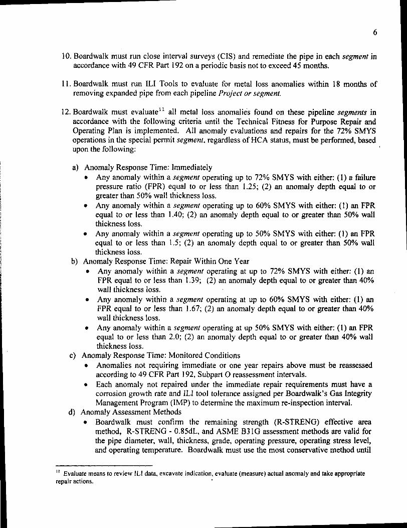
6
10 Boardwalk must run close interval surveys (CIS) and remediate the pipe in each segment in accordance with 49 CFR Part 192 on a periodic basis not to exceed 45 months
II Boardwalk must run ILl Tools to evaluate for metal loss anomalies within 18 months of removing expanded pipe from each pipeline Project or segment
12 Boardwalk must evaluatell all metal loss anomalies found on these pipeline segments in accordance with the following criteria until the Technical Fitness for Purpose Repair and Operating Plan is implemented All anomaly evaluations and repairs for the 72 SMYS operations in the special pennit segment regardless of HCA status must be performed based upon the following
a) Anomaly Response Time Immediately bull Any anomaly within a segment operating up to 72 SMYS with either (1) a failure
pressure ratio (FPR) equal to or less than 125 (2) an anomaly depth equal to or greater than 50 wall thickness loss
bull Any anomaly within a segment operating up to 60 SMYS with either (1) an FPR equal to or less than 140 (2) an anomaly depth equal to or greater than 50 wall thickness loss
bull Any anomaly within a segment operating up to 50 SMYS with either (1) an FPR equal to or less than 15 (2) an anomaly depth equal to or greater than 50 wall thickness loss
b) Anomaly Response Time Repair Within One Year bull Any anomaly within a segment operating at up to 72 SMYS with either (I) an
FPR equal to or less than 139 (2) an anomaly depth equal to or greater than 40 wall thickness loss
bull Any anomaly within a segment operating at up to 60 SMYS with either (1) an FPR equal to or less than 167 (2) an anomaly depth equal to or greater than 40 wall thickness loss
bull Any anomaly within a segment operating at up 50 SMYS with either (1) an FPR equal to or less than 20 (2) an anomaly depth equal to or greater than 40 wall thickness loss
c) Anomaly Response Time Monitored Conditions bull Anomalies not requiring immediate or one year repairs above must be reassessed
according to 49 CFR Part 192 SUbpart 0 reassessment intervals bull Each anomaly not repaired under the immediate repair requirements must have a
corrosion growth rate and ILl tool tolerance assigned per Boardwalks Gas Integrity Management Program (IMP) to determine the maximum re-inspection interval
d) Anomaly Assessment Methods bull Boardwalk must confirm the remaining strength (R-STRENG) effective area
method R-STRENG - 085dL and ASME 831G assessment methods are valid for the pipe diameter wall thickness grade operating pressure operating stress level and operating temperature Boardwalk must use the most conservative method until
1 Evaluate means to review III data excavate indication evaluate (measure) actual anomaly and take appropriate repair actions
7
confirmation of the proper method is made to the Director Engineering and Emergency Support with copies to the Directors PHMSA Southern and Southwestern Regions
13 Boardwalk must complete the 36middotinch Fayetteville Lateral Pipeline Project girth weld inspection and remediation plan as outlined below prior to operating the applicable segments above 72 SMYS as documented in Table 1
Fayetteville Lateral Project Girth Weld Inspection and Remediation Protocol
Phase I - Program Development
1 Boardwalk must review the welding weld repair and nondestructive testing (NDT) procedures that were used for the repair of the girth weld that failed during hydrostatic testing to ensure there are no technical problems with the procedures
2 Boardwalk must review the Fayetteville Lateral Project construction records to identify locate and catalog all girth weld repairs completed with the same procedures used on the failed girth weld
3 Boardwalk must review the Fayetteville Lateral Project specifications and construction records regarding the actual placement of supports underneath the pipe at tiemiddotins overmiddotbends sag-bends and other areas of high stress to ensure that high stresses are not occurring on the Fayetteville Lateral Project as a result of inadequate pipe support
4 The girth weld inspection and remediation program must include the nondestructive testing (NOT) and repair (if necessary) of girth welds along the Fayetteville Lateral Project with special emphasis on those areas of the pipeline subjected to the highest external loading Boardwalk must identify investigate and where necessary remediate previously repaired girth welds that meet the following criteria
a) On any previously repaired girth weld where welding andlor NDT procedures may not have been properly followed b) On any repaired girth welds in the vicinity of the failed girth weld with a minimum remiddotinspection of three repaired girth welds upstream and three downstream of the failed girth weld c) On any repaired girth welds in agricultural areas where heavy farm equipment may add to overburden stresses d) On any repaired girth welds on the top and bottom of the pipe and e) On any repaired girth welds near overmiddot bends or sag-bends
5 Boardwalk must submit the findings of the Fayetteville Lateral Project Girth Weld Inspection and Remediation Protocol Items 1 2 and 3 above and the
8
framework of the girth weld inspection and remediation program (Item 4) to the Director Engineering and Emergency Support with copies to the Directors PHMSA Southern and Southwestern Regions for review prior to beginning any excavations
Phase II - Program Implementation
1 Boardwalk must implement the program as described above
2 If problems are discovered after the girth weld inspection and remediation program is implemented Boardwalk must also address each of the following as required
(a) Repair girth welds on hilltops
(b) Repair girth welds where hi-Io pipe alignment issues were not resolved by shims (c) Repair girth welds at excessive depth locations (d) Repair girth welds in the downstream section of compressor stations and (e) Repair girth welds in other areas determined to be of high risk from excessive external forces such as bored crossings of highwaysrailroads and at valve settings
3 Boardwalk must submit all the findings and results of the girth weld inspection and remediation program to the Director Engineering and Emergency Support with copies to the Directors PHMSA Southern and Southwestern Regions for review
14 Should Boardwalk find through the deformation tool evaluations and excavations of the identified anomalies or develop any additional information whether through the investigation or testing described otherwise herein that may technically warrant a modification of any of the provisions of this agreement Boardwalk may notify the Director Engineering and Emergency Support with copies to the Directors Southern and Southwestern Regions of these findings and request approval of the proposed modifications
1S Boardwalk is to submit quarterly reports to the Director Engineering and Emergency Support with copies to the Directors Southern and Southwestern Regions that (I) include available data and results of the testing and evaluations required by this Agreement and (2) describe the progress of the repairs and other remedial actions being undertaken The first quarterly report shall be due June 1 2009
16 The Director may allow the removal or modification of the pressure restriction set forth in the Agreement upon a written request from Boardwalk demonstrating that the potentially low yield strength risk has been abated and that restoring the affected pipeline or portion thereof to its otherwise applicable MAOP is justified based on a reliable engineering analysis or other mutually agreeable data including industry publications or studies showing that the pressure increase is safe considering all known physical properties and operating parameters of the pipeline
9
III Relationship to Original MAOP Special Permits
The additional conditions set forth in this Agreement are in addition to the conditions in the original special permits and Boardwalk must comply with both the original special permit terms and this Agreement To the extent a term or condition in the original special permit and this Agreement are in conflict the condition in this Agreement is controlling
IV Review and Approval Process
All submissions required or allowed under this Agreement should be submitted electronically in the absence of good cause to do otherwise With respect to each submission that under this Agreement requires the approval of the Director Engineering and Emergency Support the Director may (a) approve in whole or in part the submission (b) approve the submission on specified conditions (c) disapprove in whole or in part the submission or (d) any combination of the foregoing In the event of approval approval in part or approval with conditions Boardwalk will proceed to take all action required by the submission as approved by the Director In the event that the Director disapproves all or any portion of the submission the Director will provide Boardwalk with prompt written notice of the deficiencies and the specific additional action needed to obtain approval Boardwalk will correct all deficiencies within the reasonable time specified by the Director and resubmit it for approval
V Enforcement
This Agreement is incorporated into the special permits issued by PHMSA for the specified pipelines and is subject to all enforcement authorities available to PHMSA under 49 USC sect 60101 et seq and 49 CFR Part 190 including administrative civil penalties under sect 60122 of up to $100000 per violation for each day the violation continues if PHMSA determines that Boardwalk is not proceeding in accordance with terms of the agreement determinations made by the Regional Director or if appealed decisions of the Associate Administrator Any work plans and associated schedules shall be automatically incorporated into this Agreement and are enforceable in the same manner Notwithstanding anything herein Boardwalk shall have all of its legal rights to challenge appeal or otherwise contest any proposed enforcement authority asserted for alleged non-compliance with this Agreement
VI Modification
The terms of this Agreement may be modified by mutual agreement of the parties Such modifications shall be in writing and shall be signed by both parties
VII Termination
This Agreement shall terminate upon the completion of all terms set forth in Section II (Additional Special Permit Conditions) Boardwalk may request written confirmation from PHMSA when this Agreement is terminated To the extent ongoing monitoring is required
10
PHMSA may terminate this Agreement with respect to all other requirements with the exception of such monitoring Nothing in this Agreement prevents Boardwalk from completing any of the obligations earlier than the deadlines provided for herein
VIII Ratification
The parties undersigned representatives certify that they are fully authorized to enter into the terms and conditions of this Agreement and to execute and legally bind such party to this document
On behalf of Boardwalk I hereby agree to all conditions and terms of this Agreement and agree to implement this Agreement on the referenced pipeline projects and segments
Walter Bennett Date Senior Vice President of Operations Boardwalk Pipeline Partners LP
~Ihte DateY40JJeffrey D Wiese Associate Administrator for Pipeline Safety
1
US DEPARTMENT OF TRANSPORTATION
PIPELINE AND HAZARDOUS MATERIALS SAFETY ADMINISTRATION (PHMSA)
SPECIAL PERMIT
Docket Number PHMSA-200S-006S
Requested By Gulf Crossing Pipeline Company LLC and Gulf South Pipeline Company LP
[subsidiaries ofBoardwalk Pipeline Partners LP]
Date Requested December 31 2007
Code Sections 49 CFR sectsect 192111 and 192201
Grant of Special Permit
By this order The Pipeline and Hazardous Materials Safety Administration (PHMSA) grants this
special permit to the Gulf Crossing Pipeline Company LLC (GCPC) and Gulf South Pipeline
Company LP (GSPC) [subsidiaries ofBoardwalk Pipeline Partners LP] subject to the
conditions and limitations set forth below The special permit waives compliance from 49 CFR
sect 192111 and sect 192201 for the Gulf Crossing Project (GCP) pipeline a proposed 3532-mile
42-inch diameter natural gas transmission pipeline to be installed and operated by GCPC from
Grayson County Texas to Madison Parish Louisiana The special permit also waives
compliance from 49 CFR sect 192111 and sect 192201 for the Mississippi Loop (ML) a 17S-mile
42-inch diameter natural gas transmission loop pipeline to be installed and operated by GSPC in
Hinds Copiah and Simpson Counties Mississippi
This special permit allows GCPC to design construct and operate the GCP pipeline and the
GSPC to design construct and operate the ML pipeline in Class 1 locations using a design factor
in sect 192111 up to OSO and at stress levels up to SO ofthe specified minimum yield strength
(SMYS) in Class 2 locations using a design factor in sect 192111 up to 067 and at stress levels up
to 67 of SMYS and in Class 3 locations using a design factor in sect 192111 up to 056 and at
stress levels up to 56 of SMYS This would result in maximum allowable operating pressures
(MAOP) of 14S0 pounds per square inch gauge (PSIG)
This special permit also allows GCPC to design install and operate pressure relief and limiting
devices on the GCP pipeline and the GSPC to design install and operate pressure relief and
2
limiting devices on the ML pipeline with a capacity that would ensure the pressure in Class 1
Class 2 and Class 3 location pipeline segments would not exceed 104 ofthe MAOP or the
pressure that produces a hoop stress of 832 SMYS in Class 1 locations 697 SMYS in Class
2 locations or 582 SMYS in Class 3 locations during an overpressure event
For the purpose of this special permit the special permit area means the area consisting of the
entire pipeline right-of-way for those segments of the GCP and ML pipelines that will operate
above 72 SMYS in Class 1 locations above 60 SMYS in Class 2 locations above 50
SMYS in Class 3 locations
PHMSA grants this special permit based on the findings set forth in the Special Permit Analysis
and Findings document which can be read in its entirety in Docket No PHMSA-2008-0068 in
the Federal Docket Management System (FDMS) located on the Internet at
www Regul ationsgov
Conditions
This special permit is granted subject to the following conditions
1) Steel Properties The skelpplate must be micro alloyed fine grain fully killed steel with
calcium treatment and continuous casting
2) Manufacturing Standards The pipe must be manufactured according to American
Petroleum Institute Specification 5L Specification for Line Pipe (API 5L) product
specification level 2 (PSL 2) supplementary requirements (SR) for maximum operating
pressures and minimum operating temperatures Pipe carbon equivalents must be at or
below 023 based on the material chemistry parameter (Pcm) formula
3) Fracture Control API 5L the American Society ofMechanical Engineers B318 Standard
(ASME B318) and other specifications and standards address the steel pipe toughness
properties needed to resist crack initiation crack propagation and to ensure crack arrest
during a pipeline failure caused by a fracture GCPC and GSPC must institute an overall
fracture control plan addressing steel pipe properties necessary to resist crack initiation and
crack propagation and to arrest a fracture within 8 pipe joints with a 99 occurrence
probability or within 5 pipe joints with a 90 occurrence probability The plan must
include acceptable Charpy Impact and Drop Weight Tear Test values which are measures
3
include acceptable Charpy Impact and Drop Weight Tear Test values which are measures
of a steel pipelines toughness and resistance to fracture The fracture control plan which
must be submitted to PHMSA headquarters must be in accordance with API 5L Appendix
F and must include the following tests
a) SR 5A - Fracture Toughness Testing for Shear Area Test results must indicate at least
85 minimum average shear area for all X- 70 heats and 80 minimum shear area for
all X- 80 heats with a minimum result of 80 shear area for any single test The test
results must also ensure a ductile fracture and arrest
b) SR 5B - Fracture Toughness Testing for Absorbed Energy and
c) SR 6 - Fracture Toughness Testing by Drop Weight Tear Test Test results must be at
least 80 of the average shear area for all heats with a minimum result of 60 of the
shear area for any single test The test results must also ensure a ductile fracture and
arrest
The above fracture initiation propagation and arrest plan must account for the entire range
of pipeline operating temperatures pressures and gas compositions planned for the pipeline
diameter grade and operating stress levels including maximum pressures and minimum
temperatures for shut-in conditions associated with the special pennit area Where the use
of stress factors pipe grade operating temperatures and gas composition make fracture
toughness calculations non-conservative correction factors must be used If the fracture
control plan for the pipe in the special pennit area does not meet these specifications
GCPC and GSPC must submit to PHMSA headquarters an alternative plan providing an
acceptable method to resist crack initiation crack propagation and to arrest ductile fractures
in the special pennit area
4) Steel Plate Quality Control The steel mill andor pipe rolling mill must incorporate a
comprehensive platecoil mill and pipe mill inspection program to check for defects and
inclusions that could affect the pipe quality This program must include a plate or rolled
pipe ultrasonic testing (UT) inspection program to check for imperfections such as
laminations UT inspection must be conducted on all factory beveled pipe ends In
addition pipe body UT inspection must be conducted on a minimum of 100 of pipe joints
and all ends with a minimum coverage of 35 of the pipe body for those joints inspected
Any laminations identified by the UT inspection program must be evaluated in accordance
4
with the acceptance criteria defined in ASTM International Standard ASTM A5781A578M
Standard Specification for Straight-Beam Ultrasonic Examination ofRolled Steel Plates
for Special Applications (ASTM A578) Level B or API 5L Paragraph 7810 An
inspection protocol for centerline segregation evaluation using a test method referred to as
slab macro-etching must be employed to check for inclusions that may form as the steel
plate cools after it has been cast A minimum of one macro-etch or a suitable alternative
test must be performed from the first or second heat (manufacturing run) of each sequence
(approximately 4 heats) and graded on the Mannesmann scale or equivalent Test results
with a Mannesmann scale rating of one or two out of a possible four or five scale are
acceptable
5) Pipe Seam Quality Control A quality assurance program must be instituted for pipe weld
seams The pipe weld seam tests must meet the minimum requirements for tensile strength
in API 5L for the appropriate pipe grade properties A pipe weld seam hardness test using
the Vickers hardness testing of a cross-section from the weld seam must be performed on
one length of pipe from each heat The maximum weld seam and heat affected zone
hardness must be a maximum of 280 Vickers hardness (HvlO) The hardness tests must
include a minimum of 3 readings for each heat affected zone 3 readings in the weld metal
and 2 readings in each section of pipe base metal for a total of 13 readings The pipe weld
seam must be 100 UT inspected after expansion and hydrostatic testing per API 5L
6) Mill Hydrostatic Test The pipe must be subjected to a mill hydrostatic test to achieve a
minimum stress level of 95 SMYS in the pipe for a minimum duration of 10 seconds
The 95 stress level may be achieved using a combination of internal test pressure and the
application of end loads imposed by the hydrostatic testing equipment as allowed by API
5L Appendix K
7) Pipe Coating The application of a corrosion resistant coating to the steel pipe must be
subject to a coating application quality control program The program must address pipe
surface cleanliness standards blast cleaning application temperature control adhesion
cathodic disbondment moisture permeation bending minimum coating thickness coating
imperfections and coating repair
8) Field Coating A field girth weld joint coating application specification and quality
standards to ensure pipe surface cleanliness application temperature control adhesion
5
quality cathodic disbondment moisture permeation bending minimum coating thickness
holiday detection and repair quality must be implemented in field conditions Field joint
coatings must be non-shielding to cathodic protection (CP) Field coating applicators must
use valid coating procedures and be trained to use these procedures
9) Coatings for Trenchless Installation Coatings used for directional bore slick bore and
other trenchless installation methods must resist abrasions and other damages that may
occur due to rocks and other obstructions encountered in this installation technique
10) Bends Quality Certification records of factory induction bends andor factory weld bends
must be obtained and retained All bends flanges and fittings must have carbon
equivalents (CE) below 042 or a pre-heat procedure must be applied prior to welding for
CE above 042
11) Fittings All pressure rated fittings and components (including flanges valves gaskets
pressure vessels and compressors) must be rated for a pressure rating commensurate with
the MAOP and class location of the pipelines Designed fittings (including tees elbows
and caps) must have the same design factor as the adjacent pipe
12) Design Factor - Pipelines Pipe installed under this special permit in Class 1 locations may
use a design factor of 080 in Class 2 locations may use a design factor of 067 and in
Class 3 locations may use a design factor of 056
13) Temperature Control The compressor station discharge temperature must be limited to
120deg Fahrenheit A temperature above this maximum temperature of 120deg Fahrenheit may
be approved if GCPC and GSPC technical coating operating tests show that the pipe
coating will properly withstand the higher operating temperature for long term operations
If the temperature exceeds 120deg Fahrenheit GCPC and GSPC must also institute a coating
monitoring program in these areas using ongoing Direct Current Voltage Gradient (DCVG)
surveys or Alternating Current Voltage Gradient (ACVG) surveys or other testing to
demonstrate the integrity of the coating This program and results must be provided to the
regional offices of PHMSA where the pipe is in service
14) Overpressure Protection Control Mainline pipeline overpressure protection must be
limited to a maximum of 104 MAOP
15) Welding Procedures For automatic or mechanized welding the 19th Edition of API 1104
Welding of Pipelines and Related Facilities will be used for welding procedure
6
qualification welder qualification and weld acceptance criteria Operator must use the
19th Edition of API 1104 for all other welding processes The appropriate PHMSA
regional office must be notified within 14 days of the beginning of welding procedure
qualification activities Automated or manual welding procedure documentation must be
submitted to the same PHMSA regional office
16) Depth of Cover The soil cover must be a minimum depth of 36 inches in all areas In
areas where threats from chisel plowing or other activities are threats to the pipelines the
top of the pipelines must be installed at least one foot below the deepest penetration above
the pipelines If routine patrols or other observed conditions indicate the possible loss of
cover over the pipelines GCPC and GSPC will perform a depth of cover study and replace
cover as necessary to meet the minimum depth of cover requirements specified herein
17) Construction Quality A construction quality assurance plan to ensure quality standards
and controls must be maintained throughout the construction phase with respect to
inspection pipe hauling and stringing field bending welding non-destructive examination
(NDE) of girth welds field joint coating pipeline coating integrity tests lowering of the
pipeline in the ditch padding materials to protect the pipeline backfilling alternating
current (AC) interference mitigation and CP systems All girth welds must be nonshy
destructively examined by radiography or alternative means The NDE examiner must
have all required and current certifications
18) Interference Currents Control Control of induced AC from parallel electric transmission
lines and other interference issues that may affect the pipelines must be incorporated into
the design of the pipelines and addressed during the construction phase Issues identified
and not originally addressed in the design phase must be brought to PHMSAs attention by
notifying the appropriate regional office An induced AC program to protect the pipelines
from corrosion caused by stray currents must be in place within six months after placing
the pipelines in service
19) Test Level The pre-in service hydrostatic test must be to a pressure producing a hoop
stress of at least 100 SMYS and 125 X MAOP in areas to operate up to 80 SMYS and
at least 150 X MAOP in areas to operate to 67 SMYS and 56 SMYS Short segments
of pipe (up to one mile in length) having a design factor between 72 SMYS and less than
80 SMYS may be tested with 80 SMYS pipe provided the test pressure produces a
7
hoop stress of at least 125 X MAOP for all pipe tested
20) Assessment of Test Failures Any pipe failure occurring during the pre-in service
hydrostatic test must undergo a root cause failure analysis to include a metallurgical
examination of the failed pipe The results of this examination must preclude a systemic
pipeline material issue and the results must be reported to PHMSA headquarters and the
appropriate PHMSA regional office
21) Supervisory Control and Data Acquisition (SCADA) System Capabilities A SCADA
system to provide remote monitoring and control of the pipeline system must be employed
22) SCADA Procedures A detailed procedure for establishing and maintaining accurate
SCADA set points must be established to ensure the pipelines operate within acceptable
design limits at all times
23) Mainline Valve Control Mainline valves located on either side of a pipeline segment
containing a High Consequence Area (HCA) where personnel response time to the valve
exceeds one hour must be remotely controlled via the SCADA system The SCADA
system must be capable of closing these mainline valves and monitoring the valve position
as well as upstream pressure and downstream pressure at the mainline valve As an
alternative a leak detection system for mainline valve control is acceptable
24) Pipeline Inspection The pipelines must be capable of passing in-line inspection (ILl)
tools All headers and other segments covered under this special permit that do not allow
the passage of an ILl device must have a corrosion mitigation plan
25) Gas Quality Monitoring An acceptable gas quality monitoring and mitigation program
must be instituted to not exceed the following limits
a) H2S (10 grain per 100 standard cubic feet or 16 parts per million (ppm) maximum)
b) CO2 (3 maximum)
c) H20 (less than or equal to 7 pounds per million standard cubic feet and no free water)
and
d) Other deleterious constituents that may impact the integrity of the pipelines
26) The pipelines must have an ongoing pigging and liquids sampling plan to identify mitigate
and remove deleterious constituents where applicable
27) If H2S is above 8 parts ppm the gas stream constituents must be reviewed for
implementation of a quarterly pigginginhibitor injection program including follow up
8
sampling of liquids at receipt points
28) Gas Quality Control Separators or Filtersseparators must be installed at locations where
gas is received into the pipelines where the incoming gas stream quality includes
potentially deleterious free liquids andor particulates to minimize the entry of
contaminants and to protect the integrity of downstream pipeline segments
29) Gas Quality Monitoring Equipment Equipment including moisture analyzer
chromatograph and semi-annual H2S sampling (quarterly sampling where H2S is above 8
ppm) must be installed to permit the operator to manage and limit the introduction of
contaminants and free liquids into the pipelines
30) Cathodic Protection The initial CP system must be operational within 12 months of
placing any pipeline segment in service
31) Interference Current Surveys Interference surveys must be performed within six months
of placing the pipeline in service to ensure compliance with applicable NACE International
Standard Recommended Practices 0169 and 0177 (NACE RP 0169 and NACE RP 0177)
for interference current levels If interference currents are found GCPC and GSPC will
determine if there have been any adverse affects to the pipeline and mitigate the affects as
necessary GCPC and GSPC will report the results of any negative finding and the
associated mitigative efforts to the appropriate PHMSA regional office
32) Corrosion Surveys Corrosion surveys of the affected pipelines must be completed within
six months of placing the respective CP system(s) in operation to ensure adequate external
corrosion protection per NACE RP 0169 The survey will also address the proper number
and location of CP test stations as well as AC interference mitigation and AC grounding
programs per NACE RP 0177
33) Verification of Cathodic Protection An intemlpted close interval survey (CIS) must be
performed in concert and integrated with ILl in accordance with 49 CFR 192 Part Subpart
o reassessment intervals for all HCA pipeline mileage At least one CP test station must be
located within each HCA with a maximum spacing between test stations of one-half mile
within an HCA If any annual test station reading fails to meet 49 CFR 192 Part Subpart I
requirements remedial actions must occur within six months Remedial actions must
include a CIS on each side of the affected test station and all modifications to the CP
system necessary to ensure adequate external corrosion control
9
34) Initial Close Interval Survey (CIS) - Initial A CIS must be performed on the pipelines
within two years of the pipeline in-service dates The CIS results must be integrated with
the baseline ILl to determine whether further action is needed
35) Initial Coating Assessment - GCPC and GSPC must assess the integrity of the pipelines
coating after completion of padding and backfill during constmction through use of coating
indirect assessment methods such as DCVG or ACVG surveys or equivalent methods
GCPC and GSPC must remediate any damaged coating found during these assessments
that are classified as minor and at or above 15 IR for DCVG or at or above 30 dBlV
ACVG moderate or severe based on NACE International Recommended Practice 0502shy
2002 Pipeline External Corrosion Direct Assessment Methodology (NACE RP 0502shy
2002) A minimum of two coating survey assessment classifications must be excavated
classified andor remediated per each survey crew and compressor station discharge
pipeline section to verify survey results
36) Pipeline Markers GCPC and GSPC must employ line-of-sight markings on the pipelines
in the special permit area except in agricultural areas or large water crossings such as lakes
where line-of-sight markers are not practical The marking of pipelines is also subject to
Federal Energy Regulatory Commission orders or environmental permits and local
restrictions
37) Pipeline Patrolling Pipeline patrolling must be conducted at least monthly (12 times per
calendar year) not to exceed 45 days to inspect for excavation activities ground
movement wash-outs leakage or other activities and conditions affecting the safe
operation of the pipelines
38) Monitoring of Ground Movement An effective monitoringmitigation plan must be in
place to monitor for and mitigate issues of unstable soil and ground movement
39) Initial ILl GCPC and GSPC must perform a baseline ILl in association with the
constmction of the pipelines using a high-resolution Magnetic Flux Leakage (MFL) tool to
be completed within three years of placing a pipeline segment in service GCPC and GSPC
must perform a baseline geometry tool mn after completion of the hydrostatic strength test
and backfill of the pipelines (just prior to placing the pipelines in service) but no later than
six months after placing the pipelines in service in accordance with the conditions allowed
by the special permit
10
40) Future ILl A second high-resolution MFL inspection must be performed and completed
on the pipe subject to this special permit within the first reassessment interval required by
49 CFR Part 192 Subpart 0 regardless of HCA classification Future ILl must be
performed on a frequency consistent with Subpart degfor the entire pipelines covered by this
special permit
41) Direct Assessment Plan Headers mainline valve bypasses and other sections in the
special pennit area that cannot accommodate ILl tools must be part of a Direct Assessment
(DA) plan or other acceptable integrity monitoring method using External and Internal
Corrosion Direct Assessment criteria (ECDAlICDA)
42) Damage Prevention Program The Common Ground Alliances (CGA) damage prevention
best practices applicable to pipelines must be incorporated into the GCPC and GSPC
damage prevention program
43) Anomaly Evaluation and Repair Anomaly evaluations and repairs in the special penni
area regardless of HCA status must be performed based upon the following
a) Anomaly Response Time Repair Immediately
- Any anomaly within a special penni area operating up to SO SMYS with a
failure pressure ratio (FPR) equal to or less than 11 andor an anomaly depth equal
to or greater than SO wall thickness loss
- Any anomaly within a special permit area operating up to 67 SMYS with an FPR
equal to or less than 125 andor an anomaly depth equal to or greater than SO wall
thickness loss
- Any anomaly within a special permit area operating up to 56 SMYS with an FPR
equal to or less than 14 andor an anomaly depth equal to or greater than SO wall
thickness loss
b) Anomaly Response Time Repair Within One Year
- Any anomaly within a special pennit area operating at up to SO SMYS with a
FPR equal to or less than 125
- Any anomaly within a special pennit area operating at up to 67 SMYS with a
FPR equal to or less than 15
- Any anomaly within a special pennit area operating at up 56 SMYS with an FPR
equal to or less than 1S
11
c) Anomaly Response Time Monitored Conditions
- Anomalies not requiring immediate or one year repairs per paragraphs a and b
above must be reassessed according to 49 CFR Part 192 Subpart 0 reassessment
intervals
- Each anomaly not repaired under the immediate repair requirements must have a
corrosion growth rate and ILl tool tolerance assigned per the Gas Integrity
Management Program (IMP) to determine the maximum re-inspection interval
d) Anomaly Assessment Methods
- GCPC and GSPC must confirm the remaining strength (R-STRENG) effective area
method 085dL and ASME B31 G assessment methods are valid for the pipe
diameter wall
- Thickness grade operating pressure operating stress level and operating
temperature GCPC and GSPC must also use the most conservative method until
confirmation of the proper method is made to PHMSA Headquarters
- Dents in the pipe in the special permit area must be evaluated and repaired per
49 CFR sect 192309(b) for the baseline geometry tool run and per 49 CFR
sect 192933(d) for future ILl
44) Potential Impact Radius Calculation Updates If the pipeline operating pressures and gas
quality are determined to be outside the parameters of the C-FER Study a revised study
with the updated parameters must be incorporated into the IMP
45) Reporting - Immediate GCPC and GSPC must notify the appropriate PHMSA regional
office within 24 hours of any non-reportable leaks occurring in the special permit area
46) Reporting - 30 Day At least thirty (30) days prior to the pipeline in- service date under
this special permit Operator shall report on its compliance with special permit conditions
to PHMSA headquarters and the appropriate regional offices
a) Special Permit Conditions 1 through 25 28 29 33 35 3644 and 46 must be
completed and implemented with documentation available for PHMSA review prior to
operating at the special permit MAOP
b) Special Permit Conditions 3 7 through 14 16 18 and 21 through 47 must be included
in the operators written operating and maintenance (OampM) procedures manual
12
concerning permit condition requirements with documentation available for PHMSA
review prior to operating at the special permit MAOP
47) Annual Reporting GCPC and GSPC must report the following to the appropriate PHMSA
regional offices annuallyl
a) The results of any ILl or direct assessment results performed within the special permit
area during the previous year
b) Any new integrity threats identified within the special pennit area during the previous
year
c) The number of new residences other structures intended for human occupancy and
public gathering areas built within the special pennit area
d) Any class or HCA changes in the special pennit area during the previous year
e) Any reportable incidents associated with the special permit area that occurred during
the previous year
f) Any leaks on the pipelines in the special pennit area that occurred during the previous
year
g) A list of all repairs on the pipelines in the special pennit area made during the previous
year
h) On-going damage prevention initiatives on the pipelines in the special pennit area and
a discussion of their success or failure
i) Any changes in procedures used to assess andor monitor the pipelines operating under
this special permit and
j) Any company mergers acquisitions transfers of assets or other events affecting the
regulatory responsibility of the company operating the pipelines to which this special
permit applies
Limitations
PHMSA grants this special permit subject to the following limitations
1) PHMSA has the sole authority to make all determinations on whether GCPC andor GSPC
have complied with the specified conditions of this special permit
I Annual reports must be received by PHMSA by the last day of the month in which the Special Permit is dated For example the annual report for a Special Permit dated March 4 2008 must be received by PHMSA no later than March 31 st each year beginning in 2009
F
13
2) Should GCPC andor GSPC fail to comply with any of the specified conditions of this special
permit PHMSA may revoke this special permit and require GCPC andor GSPC to comply
with the regulatory requirements in 49 CFR sectsect 192111 and 19220l
3) PHMSA may revoke suspend or modify a special permit based on any finding listed in
49 CFR sect 190341(h)(1) and require GCPC andor GSPC to comply with the regulatory
requirements in 49 CFR sectsect 192111 and 19220l
4) Should PHMSA revoke suspend or modify a special permit based on any finding listed in
49 CFR sect 190341(h)(1) PHMSA will notify GCPC andor GSPC in writing of the proposed
action and provide GCPC andor GSPC an opportunity to show cause why the action should
not be taken unless PHMSA determines that taking such action is immediately necessary to
avoid the risk of significant harm to persons property or the environment (see 49 CFR
sect 190341(h)(2raquo
5) The terms and conditions of any corrective action order compliance order or other order
applicable to a pipeline facility covered by this special permit will take precedence over the
terms of this special permit in accordance with 49 CFR sect 190341(h)(4)
AUTHORITY 49 USc 60118(c) and 49 CFR sect 153
d middot W h DC NOV 1 9 2008Issue m as mgton on ________
ttJ2f~ I-I-~ amp~
Jeffrey D Wiese
Associate Administrator for Pipeline Safety
- Bdwlk_Mod_4-30-2009
- Gulf_11-2008
-

7
confirmation of the proper method is made to the Director Engineering and Emergency Support with copies to the Directors PHMSA Southern and Southwestern Regions
13 Boardwalk must complete the 36middotinch Fayetteville Lateral Pipeline Project girth weld inspection and remediation plan as outlined below prior to operating the applicable segments above 72 SMYS as documented in Table 1
Fayetteville Lateral Project Girth Weld Inspection and Remediation Protocol
Phase I - Program Development
1 Boardwalk must review the welding weld repair and nondestructive testing (NDT) procedures that were used for the repair of the girth weld that failed during hydrostatic testing to ensure there are no technical problems with the procedures
2 Boardwalk must review the Fayetteville Lateral Project construction records to identify locate and catalog all girth weld repairs completed with the same procedures used on the failed girth weld
3 Boardwalk must review the Fayetteville Lateral Project specifications and construction records regarding the actual placement of supports underneath the pipe at tiemiddotins overmiddotbends sag-bends and other areas of high stress to ensure that high stresses are not occurring on the Fayetteville Lateral Project as a result of inadequate pipe support
4 The girth weld inspection and remediation program must include the nondestructive testing (NOT) and repair (if necessary) of girth welds along the Fayetteville Lateral Project with special emphasis on those areas of the pipeline subjected to the highest external loading Boardwalk must identify investigate and where necessary remediate previously repaired girth welds that meet the following criteria
a) On any previously repaired girth weld where welding andlor NDT procedures may not have been properly followed b) On any repaired girth welds in the vicinity of the failed girth weld with a minimum remiddotinspection of three repaired girth welds upstream and three downstream of the failed girth weld c) On any repaired girth welds in agricultural areas where heavy farm equipment may add to overburden stresses d) On any repaired girth welds on the top and bottom of the pipe and e) On any repaired girth welds near overmiddot bends or sag-bends
5 Boardwalk must submit the findings of the Fayetteville Lateral Project Girth Weld Inspection and Remediation Protocol Items 1 2 and 3 above and the
8
framework of the girth weld inspection and remediation program (Item 4) to the Director Engineering and Emergency Support with copies to the Directors PHMSA Southern and Southwestern Regions for review prior to beginning any excavations
Phase II - Program Implementation
1 Boardwalk must implement the program as described above
2 If problems are discovered after the girth weld inspection and remediation program is implemented Boardwalk must also address each of the following as required
(a) Repair girth welds on hilltops
(b) Repair girth welds where hi-Io pipe alignment issues were not resolved by shims (c) Repair girth welds at excessive depth locations (d) Repair girth welds in the downstream section of compressor stations and (e) Repair girth welds in other areas determined to be of high risk from excessive external forces such as bored crossings of highwaysrailroads and at valve settings
3 Boardwalk must submit all the findings and results of the girth weld inspection and remediation program to the Director Engineering and Emergency Support with copies to the Directors PHMSA Southern and Southwestern Regions for review
14 Should Boardwalk find through the deformation tool evaluations and excavations of the identified anomalies or develop any additional information whether through the investigation or testing described otherwise herein that may technically warrant a modification of any of the provisions of this agreement Boardwalk may notify the Director Engineering and Emergency Support with copies to the Directors Southern and Southwestern Regions of these findings and request approval of the proposed modifications
1S Boardwalk is to submit quarterly reports to the Director Engineering and Emergency Support with copies to the Directors Southern and Southwestern Regions that (I) include available data and results of the testing and evaluations required by this Agreement and (2) describe the progress of the repairs and other remedial actions being undertaken The first quarterly report shall be due June 1 2009
16 The Director may allow the removal or modification of the pressure restriction set forth in the Agreement upon a written request from Boardwalk demonstrating that the potentially low yield strength risk has been abated and that restoring the affected pipeline or portion thereof to its otherwise applicable MAOP is justified based on a reliable engineering analysis or other mutually agreeable data including industry publications or studies showing that the pressure increase is safe considering all known physical properties and operating parameters of the pipeline
9
III Relationship to Original MAOP Special Permits
The additional conditions set forth in this Agreement are in addition to the conditions in the original special permits and Boardwalk must comply with both the original special permit terms and this Agreement To the extent a term or condition in the original special permit and this Agreement are in conflict the condition in this Agreement is controlling
IV Review and Approval Process
All submissions required or allowed under this Agreement should be submitted electronically in the absence of good cause to do otherwise With respect to each submission that under this Agreement requires the approval of the Director Engineering and Emergency Support the Director may (a) approve in whole or in part the submission (b) approve the submission on specified conditions (c) disapprove in whole or in part the submission or (d) any combination of the foregoing In the event of approval approval in part or approval with conditions Boardwalk will proceed to take all action required by the submission as approved by the Director In the event that the Director disapproves all or any portion of the submission the Director will provide Boardwalk with prompt written notice of the deficiencies and the specific additional action needed to obtain approval Boardwalk will correct all deficiencies within the reasonable time specified by the Director and resubmit it for approval
V Enforcement
This Agreement is incorporated into the special permits issued by PHMSA for the specified pipelines and is subject to all enforcement authorities available to PHMSA under 49 USC sect 60101 et seq and 49 CFR Part 190 including administrative civil penalties under sect 60122 of up to $100000 per violation for each day the violation continues if PHMSA determines that Boardwalk is not proceeding in accordance with terms of the agreement determinations made by the Regional Director or if appealed decisions of the Associate Administrator Any work plans and associated schedules shall be automatically incorporated into this Agreement and are enforceable in the same manner Notwithstanding anything herein Boardwalk shall have all of its legal rights to challenge appeal or otherwise contest any proposed enforcement authority asserted for alleged non-compliance with this Agreement
VI Modification
The terms of this Agreement may be modified by mutual agreement of the parties Such modifications shall be in writing and shall be signed by both parties
VII Termination
This Agreement shall terminate upon the completion of all terms set forth in Section II (Additional Special Permit Conditions) Boardwalk may request written confirmation from PHMSA when this Agreement is terminated To the extent ongoing monitoring is required
10
PHMSA may terminate this Agreement with respect to all other requirements with the exception of such monitoring Nothing in this Agreement prevents Boardwalk from completing any of the obligations earlier than the deadlines provided for herein
VIII Ratification
The parties undersigned representatives certify that they are fully authorized to enter into the terms and conditions of this Agreement and to execute and legally bind such party to this document
On behalf of Boardwalk I hereby agree to all conditions and terms of this Agreement and agree to implement this Agreement on the referenced pipeline projects and segments
Walter Bennett Date Senior Vice President of Operations Boardwalk Pipeline Partners LP
~Ihte DateY40JJeffrey D Wiese Associate Administrator for Pipeline Safety
1
US DEPARTMENT OF TRANSPORTATION
PIPELINE AND HAZARDOUS MATERIALS SAFETY ADMINISTRATION (PHMSA)
SPECIAL PERMIT
Docket Number PHMSA-200S-006S
Requested By Gulf Crossing Pipeline Company LLC and Gulf South Pipeline Company LP
[subsidiaries ofBoardwalk Pipeline Partners LP]
Date Requested December 31 2007
Code Sections 49 CFR sectsect 192111 and 192201
Grant of Special Permit
By this order The Pipeline and Hazardous Materials Safety Administration (PHMSA) grants this
special permit to the Gulf Crossing Pipeline Company LLC (GCPC) and Gulf South Pipeline
Company LP (GSPC) [subsidiaries ofBoardwalk Pipeline Partners LP] subject to the
conditions and limitations set forth below The special permit waives compliance from 49 CFR
sect 192111 and sect 192201 for the Gulf Crossing Project (GCP) pipeline a proposed 3532-mile
42-inch diameter natural gas transmission pipeline to be installed and operated by GCPC from
Grayson County Texas to Madison Parish Louisiana The special permit also waives
compliance from 49 CFR sect 192111 and sect 192201 for the Mississippi Loop (ML) a 17S-mile
42-inch diameter natural gas transmission loop pipeline to be installed and operated by GSPC in
Hinds Copiah and Simpson Counties Mississippi
This special permit allows GCPC to design construct and operate the GCP pipeline and the
GSPC to design construct and operate the ML pipeline in Class 1 locations using a design factor
in sect 192111 up to OSO and at stress levels up to SO ofthe specified minimum yield strength
(SMYS) in Class 2 locations using a design factor in sect 192111 up to 067 and at stress levels up
to 67 of SMYS and in Class 3 locations using a design factor in sect 192111 up to 056 and at
stress levels up to 56 of SMYS This would result in maximum allowable operating pressures
(MAOP) of 14S0 pounds per square inch gauge (PSIG)
This special permit also allows GCPC to design install and operate pressure relief and limiting
devices on the GCP pipeline and the GSPC to design install and operate pressure relief and
2
limiting devices on the ML pipeline with a capacity that would ensure the pressure in Class 1
Class 2 and Class 3 location pipeline segments would not exceed 104 ofthe MAOP or the
pressure that produces a hoop stress of 832 SMYS in Class 1 locations 697 SMYS in Class
2 locations or 582 SMYS in Class 3 locations during an overpressure event
For the purpose of this special permit the special permit area means the area consisting of the
entire pipeline right-of-way for those segments of the GCP and ML pipelines that will operate
above 72 SMYS in Class 1 locations above 60 SMYS in Class 2 locations above 50
SMYS in Class 3 locations
PHMSA grants this special permit based on the findings set forth in the Special Permit Analysis
and Findings document which can be read in its entirety in Docket No PHMSA-2008-0068 in
the Federal Docket Management System (FDMS) located on the Internet at
www Regul ationsgov
Conditions
This special permit is granted subject to the following conditions
1) Steel Properties The skelpplate must be micro alloyed fine grain fully killed steel with
calcium treatment and continuous casting
2) Manufacturing Standards The pipe must be manufactured according to American
Petroleum Institute Specification 5L Specification for Line Pipe (API 5L) product
specification level 2 (PSL 2) supplementary requirements (SR) for maximum operating
pressures and minimum operating temperatures Pipe carbon equivalents must be at or
below 023 based on the material chemistry parameter (Pcm) formula
3) Fracture Control API 5L the American Society ofMechanical Engineers B318 Standard
(ASME B318) and other specifications and standards address the steel pipe toughness
properties needed to resist crack initiation crack propagation and to ensure crack arrest
during a pipeline failure caused by a fracture GCPC and GSPC must institute an overall
fracture control plan addressing steel pipe properties necessary to resist crack initiation and
crack propagation and to arrest a fracture within 8 pipe joints with a 99 occurrence
probability or within 5 pipe joints with a 90 occurrence probability The plan must
include acceptable Charpy Impact and Drop Weight Tear Test values which are measures
3
include acceptable Charpy Impact and Drop Weight Tear Test values which are measures
of a steel pipelines toughness and resistance to fracture The fracture control plan which
must be submitted to PHMSA headquarters must be in accordance with API 5L Appendix
F and must include the following tests
a) SR 5A - Fracture Toughness Testing for Shear Area Test results must indicate at least
85 minimum average shear area for all X- 70 heats and 80 minimum shear area for
all X- 80 heats with a minimum result of 80 shear area for any single test The test
results must also ensure a ductile fracture and arrest
b) SR 5B - Fracture Toughness Testing for Absorbed Energy and
c) SR 6 - Fracture Toughness Testing by Drop Weight Tear Test Test results must be at
least 80 of the average shear area for all heats with a minimum result of 60 of the
shear area for any single test The test results must also ensure a ductile fracture and
arrest
The above fracture initiation propagation and arrest plan must account for the entire range
of pipeline operating temperatures pressures and gas compositions planned for the pipeline
diameter grade and operating stress levels including maximum pressures and minimum
temperatures for shut-in conditions associated with the special pennit area Where the use
of stress factors pipe grade operating temperatures and gas composition make fracture
toughness calculations non-conservative correction factors must be used If the fracture
control plan for the pipe in the special pennit area does not meet these specifications
GCPC and GSPC must submit to PHMSA headquarters an alternative plan providing an
acceptable method to resist crack initiation crack propagation and to arrest ductile fractures
in the special pennit area
4) Steel Plate Quality Control The steel mill andor pipe rolling mill must incorporate a
comprehensive platecoil mill and pipe mill inspection program to check for defects and
inclusions that could affect the pipe quality This program must include a plate or rolled
pipe ultrasonic testing (UT) inspection program to check for imperfections such as
laminations UT inspection must be conducted on all factory beveled pipe ends In
addition pipe body UT inspection must be conducted on a minimum of 100 of pipe joints
and all ends with a minimum coverage of 35 of the pipe body for those joints inspected
Any laminations identified by the UT inspection program must be evaluated in accordance
4
with the acceptance criteria defined in ASTM International Standard ASTM A5781A578M
Standard Specification for Straight-Beam Ultrasonic Examination ofRolled Steel Plates
for Special Applications (ASTM A578) Level B or API 5L Paragraph 7810 An
inspection protocol for centerline segregation evaluation using a test method referred to as
slab macro-etching must be employed to check for inclusions that may form as the steel
plate cools after it has been cast A minimum of one macro-etch or a suitable alternative
test must be performed from the first or second heat (manufacturing run) of each sequence
(approximately 4 heats) and graded on the Mannesmann scale or equivalent Test results
with a Mannesmann scale rating of one or two out of a possible four or five scale are
acceptable
5) Pipe Seam Quality Control A quality assurance program must be instituted for pipe weld
seams The pipe weld seam tests must meet the minimum requirements for tensile strength
in API 5L for the appropriate pipe grade properties A pipe weld seam hardness test using
the Vickers hardness testing of a cross-section from the weld seam must be performed on
one length of pipe from each heat The maximum weld seam and heat affected zone
hardness must be a maximum of 280 Vickers hardness (HvlO) The hardness tests must
include a minimum of 3 readings for each heat affected zone 3 readings in the weld metal
and 2 readings in each section of pipe base metal for a total of 13 readings The pipe weld
seam must be 100 UT inspected after expansion and hydrostatic testing per API 5L
6) Mill Hydrostatic Test The pipe must be subjected to a mill hydrostatic test to achieve a
minimum stress level of 95 SMYS in the pipe for a minimum duration of 10 seconds
The 95 stress level may be achieved using a combination of internal test pressure and the
application of end loads imposed by the hydrostatic testing equipment as allowed by API
5L Appendix K
7) Pipe Coating The application of a corrosion resistant coating to the steel pipe must be
subject to a coating application quality control program The program must address pipe
surface cleanliness standards blast cleaning application temperature control adhesion
cathodic disbondment moisture permeation bending minimum coating thickness coating
imperfections and coating repair
8) Field Coating A field girth weld joint coating application specification and quality
standards to ensure pipe surface cleanliness application temperature control adhesion
5
quality cathodic disbondment moisture permeation bending minimum coating thickness
holiday detection and repair quality must be implemented in field conditions Field joint
coatings must be non-shielding to cathodic protection (CP) Field coating applicators must
use valid coating procedures and be trained to use these procedures
9) Coatings for Trenchless Installation Coatings used for directional bore slick bore and
other trenchless installation methods must resist abrasions and other damages that may
occur due to rocks and other obstructions encountered in this installation technique
10) Bends Quality Certification records of factory induction bends andor factory weld bends
must be obtained and retained All bends flanges and fittings must have carbon
equivalents (CE) below 042 or a pre-heat procedure must be applied prior to welding for
CE above 042
11) Fittings All pressure rated fittings and components (including flanges valves gaskets
pressure vessels and compressors) must be rated for a pressure rating commensurate with
the MAOP and class location of the pipelines Designed fittings (including tees elbows
and caps) must have the same design factor as the adjacent pipe
12) Design Factor - Pipelines Pipe installed under this special permit in Class 1 locations may
use a design factor of 080 in Class 2 locations may use a design factor of 067 and in
Class 3 locations may use a design factor of 056
13) Temperature Control The compressor station discharge temperature must be limited to
120deg Fahrenheit A temperature above this maximum temperature of 120deg Fahrenheit may
be approved if GCPC and GSPC technical coating operating tests show that the pipe
coating will properly withstand the higher operating temperature for long term operations
If the temperature exceeds 120deg Fahrenheit GCPC and GSPC must also institute a coating
monitoring program in these areas using ongoing Direct Current Voltage Gradient (DCVG)
surveys or Alternating Current Voltage Gradient (ACVG) surveys or other testing to
demonstrate the integrity of the coating This program and results must be provided to the
regional offices of PHMSA where the pipe is in service
14) Overpressure Protection Control Mainline pipeline overpressure protection must be
limited to a maximum of 104 MAOP
15) Welding Procedures For automatic or mechanized welding the 19th Edition of API 1104
Welding of Pipelines and Related Facilities will be used for welding procedure
6
qualification welder qualification and weld acceptance criteria Operator must use the
19th Edition of API 1104 for all other welding processes The appropriate PHMSA
regional office must be notified within 14 days of the beginning of welding procedure
qualification activities Automated or manual welding procedure documentation must be
submitted to the same PHMSA regional office
16) Depth of Cover The soil cover must be a minimum depth of 36 inches in all areas In
areas where threats from chisel plowing or other activities are threats to the pipelines the
top of the pipelines must be installed at least one foot below the deepest penetration above
the pipelines If routine patrols or other observed conditions indicate the possible loss of
cover over the pipelines GCPC and GSPC will perform a depth of cover study and replace
cover as necessary to meet the minimum depth of cover requirements specified herein
17) Construction Quality A construction quality assurance plan to ensure quality standards
and controls must be maintained throughout the construction phase with respect to
inspection pipe hauling and stringing field bending welding non-destructive examination
(NDE) of girth welds field joint coating pipeline coating integrity tests lowering of the
pipeline in the ditch padding materials to protect the pipeline backfilling alternating
current (AC) interference mitigation and CP systems All girth welds must be nonshy
destructively examined by radiography or alternative means The NDE examiner must
have all required and current certifications
18) Interference Currents Control Control of induced AC from parallel electric transmission
lines and other interference issues that may affect the pipelines must be incorporated into
the design of the pipelines and addressed during the construction phase Issues identified
and not originally addressed in the design phase must be brought to PHMSAs attention by
notifying the appropriate regional office An induced AC program to protect the pipelines
from corrosion caused by stray currents must be in place within six months after placing
the pipelines in service
19) Test Level The pre-in service hydrostatic test must be to a pressure producing a hoop
stress of at least 100 SMYS and 125 X MAOP in areas to operate up to 80 SMYS and
at least 150 X MAOP in areas to operate to 67 SMYS and 56 SMYS Short segments
of pipe (up to one mile in length) having a design factor between 72 SMYS and less than
80 SMYS may be tested with 80 SMYS pipe provided the test pressure produces a
7
hoop stress of at least 125 X MAOP for all pipe tested
20) Assessment of Test Failures Any pipe failure occurring during the pre-in service
hydrostatic test must undergo a root cause failure analysis to include a metallurgical
examination of the failed pipe The results of this examination must preclude a systemic
pipeline material issue and the results must be reported to PHMSA headquarters and the
appropriate PHMSA regional office
21) Supervisory Control and Data Acquisition (SCADA) System Capabilities A SCADA
system to provide remote monitoring and control of the pipeline system must be employed
22) SCADA Procedures A detailed procedure for establishing and maintaining accurate
SCADA set points must be established to ensure the pipelines operate within acceptable
design limits at all times
23) Mainline Valve Control Mainline valves located on either side of a pipeline segment
containing a High Consequence Area (HCA) where personnel response time to the valve
exceeds one hour must be remotely controlled via the SCADA system The SCADA
system must be capable of closing these mainline valves and monitoring the valve position
as well as upstream pressure and downstream pressure at the mainline valve As an
alternative a leak detection system for mainline valve control is acceptable
24) Pipeline Inspection The pipelines must be capable of passing in-line inspection (ILl)
tools All headers and other segments covered under this special permit that do not allow
the passage of an ILl device must have a corrosion mitigation plan
25) Gas Quality Monitoring An acceptable gas quality monitoring and mitigation program
must be instituted to not exceed the following limits
a) H2S (10 grain per 100 standard cubic feet or 16 parts per million (ppm) maximum)
b) CO2 (3 maximum)
c) H20 (less than or equal to 7 pounds per million standard cubic feet and no free water)
and
d) Other deleterious constituents that may impact the integrity of the pipelines
26) The pipelines must have an ongoing pigging and liquids sampling plan to identify mitigate
and remove deleterious constituents where applicable
27) If H2S is above 8 parts ppm the gas stream constituents must be reviewed for
implementation of a quarterly pigginginhibitor injection program including follow up
8
sampling of liquids at receipt points
28) Gas Quality Control Separators or Filtersseparators must be installed at locations where
gas is received into the pipelines where the incoming gas stream quality includes
potentially deleterious free liquids andor particulates to minimize the entry of
contaminants and to protect the integrity of downstream pipeline segments
29) Gas Quality Monitoring Equipment Equipment including moisture analyzer
chromatograph and semi-annual H2S sampling (quarterly sampling where H2S is above 8
ppm) must be installed to permit the operator to manage and limit the introduction of
contaminants and free liquids into the pipelines
30) Cathodic Protection The initial CP system must be operational within 12 months of
placing any pipeline segment in service
31) Interference Current Surveys Interference surveys must be performed within six months
of placing the pipeline in service to ensure compliance with applicable NACE International
Standard Recommended Practices 0169 and 0177 (NACE RP 0169 and NACE RP 0177)
for interference current levels If interference currents are found GCPC and GSPC will
determine if there have been any adverse affects to the pipeline and mitigate the affects as
necessary GCPC and GSPC will report the results of any negative finding and the
associated mitigative efforts to the appropriate PHMSA regional office
32) Corrosion Surveys Corrosion surveys of the affected pipelines must be completed within
six months of placing the respective CP system(s) in operation to ensure adequate external
corrosion protection per NACE RP 0169 The survey will also address the proper number
and location of CP test stations as well as AC interference mitigation and AC grounding
programs per NACE RP 0177
33) Verification of Cathodic Protection An intemlpted close interval survey (CIS) must be
performed in concert and integrated with ILl in accordance with 49 CFR 192 Part Subpart
o reassessment intervals for all HCA pipeline mileage At least one CP test station must be
located within each HCA with a maximum spacing between test stations of one-half mile
within an HCA If any annual test station reading fails to meet 49 CFR 192 Part Subpart I
requirements remedial actions must occur within six months Remedial actions must
include a CIS on each side of the affected test station and all modifications to the CP
system necessary to ensure adequate external corrosion control
9
34) Initial Close Interval Survey (CIS) - Initial A CIS must be performed on the pipelines
within two years of the pipeline in-service dates The CIS results must be integrated with
the baseline ILl to determine whether further action is needed
35) Initial Coating Assessment - GCPC and GSPC must assess the integrity of the pipelines
coating after completion of padding and backfill during constmction through use of coating
indirect assessment methods such as DCVG or ACVG surveys or equivalent methods
GCPC and GSPC must remediate any damaged coating found during these assessments
that are classified as minor and at or above 15 IR for DCVG or at or above 30 dBlV
ACVG moderate or severe based on NACE International Recommended Practice 0502shy
2002 Pipeline External Corrosion Direct Assessment Methodology (NACE RP 0502shy
2002) A minimum of two coating survey assessment classifications must be excavated
classified andor remediated per each survey crew and compressor station discharge
pipeline section to verify survey results
36) Pipeline Markers GCPC and GSPC must employ line-of-sight markings on the pipelines
in the special permit area except in agricultural areas or large water crossings such as lakes
where line-of-sight markers are not practical The marking of pipelines is also subject to
Federal Energy Regulatory Commission orders or environmental permits and local
restrictions
37) Pipeline Patrolling Pipeline patrolling must be conducted at least monthly (12 times per
calendar year) not to exceed 45 days to inspect for excavation activities ground
movement wash-outs leakage or other activities and conditions affecting the safe
operation of the pipelines
38) Monitoring of Ground Movement An effective monitoringmitigation plan must be in
place to monitor for and mitigate issues of unstable soil and ground movement
39) Initial ILl GCPC and GSPC must perform a baseline ILl in association with the
constmction of the pipelines using a high-resolution Magnetic Flux Leakage (MFL) tool to
be completed within three years of placing a pipeline segment in service GCPC and GSPC
must perform a baseline geometry tool mn after completion of the hydrostatic strength test
and backfill of the pipelines (just prior to placing the pipelines in service) but no later than
six months after placing the pipelines in service in accordance with the conditions allowed
by the special permit
10
40) Future ILl A second high-resolution MFL inspection must be performed and completed
on the pipe subject to this special permit within the first reassessment interval required by
49 CFR Part 192 Subpart 0 regardless of HCA classification Future ILl must be
performed on a frequency consistent with Subpart degfor the entire pipelines covered by this
special permit
41) Direct Assessment Plan Headers mainline valve bypasses and other sections in the
special pennit area that cannot accommodate ILl tools must be part of a Direct Assessment
(DA) plan or other acceptable integrity monitoring method using External and Internal
Corrosion Direct Assessment criteria (ECDAlICDA)
42) Damage Prevention Program The Common Ground Alliances (CGA) damage prevention
best practices applicable to pipelines must be incorporated into the GCPC and GSPC
damage prevention program
43) Anomaly Evaluation and Repair Anomaly evaluations and repairs in the special penni
area regardless of HCA status must be performed based upon the following
a) Anomaly Response Time Repair Immediately
- Any anomaly within a special penni area operating up to SO SMYS with a
failure pressure ratio (FPR) equal to or less than 11 andor an anomaly depth equal
to or greater than SO wall thickness loss
- Any anomaly within a special permit area operating up to 67 SMYS with an FPR
equal to or less than 125 andor an anomaly depth equal to or greater than SO wall
thickness loss
- Any anomaly within a special permit area operating up to 56 SMYS with an FPR
equal to or less than 14 andor an anomaly depth equal to or greater than SO wall
thickness loss
b) Anomaly Response Time Repair Within One Year
- Any anomaly within a special pennit area operating at up to SO SMYS with a
FPR equal to or less than 125
- Any anomaly within a special pennit area operating at up to 67 SMYS with a
FPR equal to or less than 15
- Any anomaly within a special pennit area operating at up 56 SMYS with an FPR
equal to or less than 1S
11
c) Anomaly Response Time Monitored Conditions
- Anomalies not requiring immediate or one year repairs per paragraphs a and b
above must be reassessed according to 49 CFR Part 192 Subpart 0 reassessment
intervals
- Each anomaly not repaired under the immediate repair requirements must have a
corrosion growth rate and ILl tool tolerance assigned per the Gas Integrity
Management Program (IMP) to determine the maximum re-inspection interval
d) Anomaly Assessment Methods
- GCPC and GSPC must confirm the remaining strength (R-STRENG) effective area
method 085dL and ASME B31 G assessment methods are valid for the pipe
diameter wall
- Thickness grade operating pressure operating stress level and operating
temperature GCPC and GSPC must also use the most conservative method until
confirmation of the proper method is made to PHMSA Headquarters
- Dents in the pipe in the special permit area must be evaluated and repaired per
49 CFR sect 192309(b) for the baseline geometry tool run and per 49 CFR
sect 192933(d) for future ILl
44) Potential Impact Radius Calculation Updates If the pipeline operating pressures and gas
quality are determined to be outside the parameters of the C-FER Study a revised study
with the updated parameters must be incorporated into the IMP
45) Reporting - Immediate GCPC and GSPC must notify the appropriate PHMSA regional
office within 24 hours of any non-reportable leaks occurring in the special permit area
46) Reporting - 30 Day At least thirty (30) days prior to the pipeline in- service date under
this special permit Operator shall report on its compliance with special permit conditions
to PHMSA headquarters and the appropriate regional offices
a) Special Permit Conditions 1 through 25 28 29 33 35 3644 and 46 must be
completed and implemented with documentation available for PHMSA review prior to
operating at the special permit MAOP
b) Special Permit Conditions 3 7 through 14 16 18 and 21 through 47 must be included
in the operators written operating and maintenance (OampM) procedures manual
12
concerning permit condition requirements with documentation available for PHMSA
review prior to operating at the special permit MAOP
47) Annual Reporting GCPC and GSPC must report the following to the appropriate PHMSA
regional offices annuallyl
a) The results of any ILl or direct assessment results performed within the special permit
area during the previous year
b) Any new integrity threats identified within the special pennit area during the previous
year
c) The number of new residences other structures intended for human occupancy and
public gathering areas built within the special pennit area
d) Any class or HCA changes in the special pennit area during the previous year
e) Any reportable incidents associated with the special permit area that occurred during
the previous year
f) Any leaks on the pipelines in the special pennit area that occurred during the previous
year
g) A list of all repairs on the pipelines in the special pennit area made during the previous
year
h) On-going damage prevention initiatives on the pipelines in the special pennit area and
a discussion of their success or failure
i) Any changes in procedures used to assess andor monitor the pipelines operating under
this special permit and
j) Any company mergers acquisitions transfers of assets or other events affecting the
regulatory responsibility of the company operating the pipelines to which this special
permit applies
Limitations
PHMSA grants this special permit subject to the following limitations
1) PHMSA has the sole authority to make all determinations on whether GCPC andor GSPC
have complied with the specified conditions of this special permit
I Annual reports must be received by PHMSA by the last day of the month in which the Special Permit is dated For example the annual report for a Special Permit dated March 4 2008 must be received by PHMSA no later than March 31 st each year beginning in 2009
F
13
2) Should GCPC andor GSPC fail to comply with any of the specified conditions of this special
permit PHMSA may revoke this special permit and require GCPC andor GSPC to comply
with the regulatory requirements in 49 CFR sectsect 192111 and 19220l
3) PHMSA may revoke suspend or modify a special permit based on any finding listed in
49 CFR sect 190341(h)(1) and require GCPC andor GSPC to comply with the regulatory
requirements in 49 CFR sectsect 192111 and 19220l
4) Should PHMSA revoke suspend or modify a special permit based on any finding listed in
49 CFR sect 190341(h)(1) PHMSA will notify GCPC andor GSPC in writing of the proposed
action and provide GCPC andor GSPC an opportunity to show cause why the action should
not be taken unless PHMSA determines that taking such action is immediately necessary to
avoid the risk of significant harm to persons property or the environment (see 49 CFR
sect 190341(h)(2raquo
5) The terms and conditions of any corrective action order compliance order or other order
applicable to a pipeline facility covered by this special permit will take precedence over the
terms of this special permit in accordance with 49 CFR sect 190341(h)(4)
AUTHORITY 49 USc 60118(c) and 49 CFR sect 153
d middot W h DC NOV 1 9 2008Issue m as mgton on ________
ttJ2f~ I-I-~ amp~
Jeffrey D Wiese
Associate Administrator for Pipeline Safety
- Bdwlk_Mod_4-30-2009
- Gulf_11-2008
-
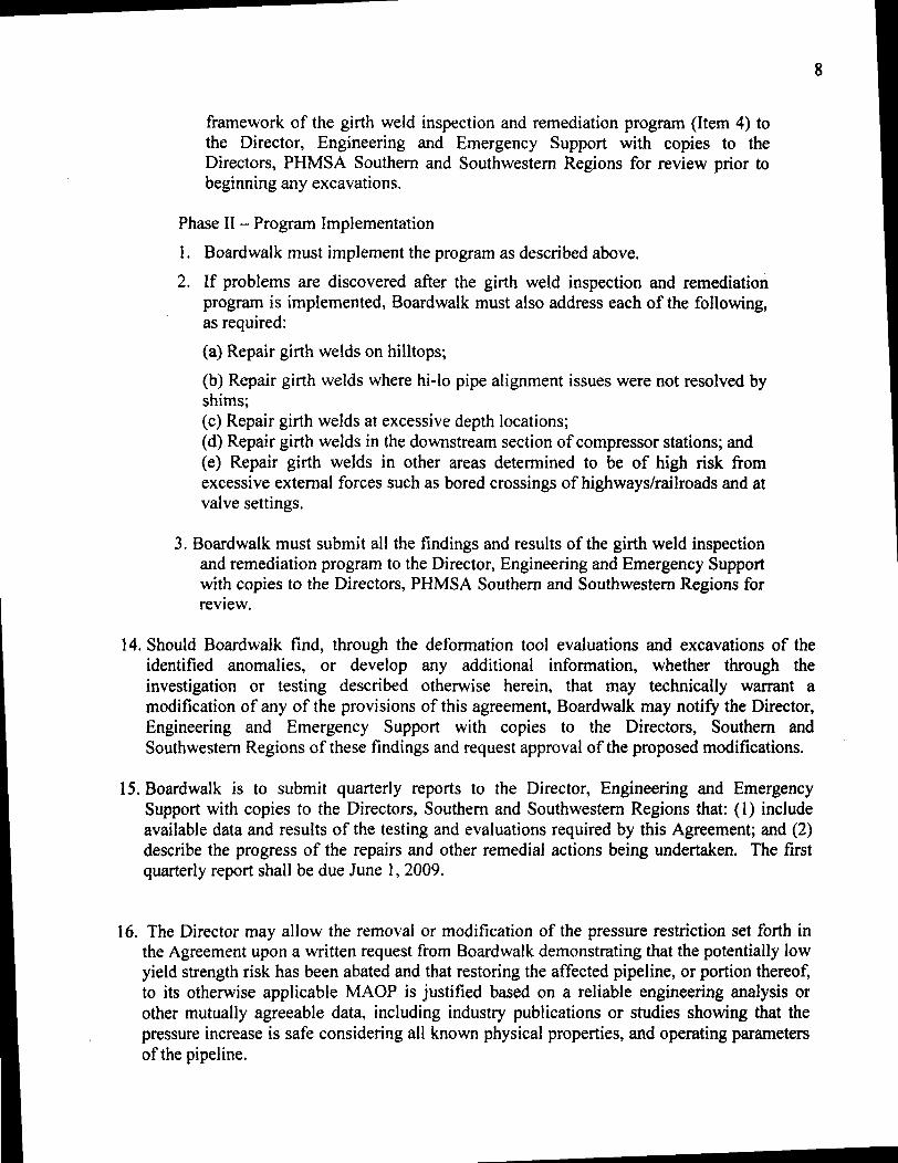
8
framework of the girth weld inspection and remediation program (Item 4) to the Director Engineering and Emergency Support with copies to the Directors PHMSA Southern and Southwestern Regions for review prior to beginning any excavations
Phase II - Program Implementation
1 Boardwalk must implement the program as described above
2 If problems are discovered after the girth weld inspection and remediation program is implemented Boardwalk must also address each of the following as required
(a) Repair girth welds on hilltops
(b) Repair girth welds where hi-Io pipe alignment issues were not resolved by shims (c) Repair girth welds at excessive depth locations (d) Repair girth welds in the downstream section of compressor stations and (e) Repair girth welds in other areas determined to be of high risk from excessive external forces such as bored crossings of highwaysrailroads and at valve settings
3 Boardwalk must submit all the findings and results of the girth weld inspection and remediation program to the Director Engineering and Emergency Support with copies to the Directors PHMSA Southern and Southwestern Regions for review
14 Should Boardwalk find through the deformation tool evaluations and excavations of the identified anomalies or develop any additional information whether through the investigation or testing described otherwise herein that may technically warrant a modification of any of the provisions of this agreement Boardwalk may notify the Director Engineering and Emergency Support with copies to the Directors Southern and Southwestern Regions of these findings and request approval of the proposed modifications
1S Boardwalk is to submit quarterly reports to the Director Engineering and Emergency Support with copies to the Directors Southern and Southwestern Regions that (I) include available data and results of the testing and evaluations required by this Agreement and (2) describe the progress of the repairs and other remedial actions being undertaken The first quarterly report shall be due June 1 2009
16 The Director may allow the removal or modification of the pressure restriction set forth in the Agreement upon a written request from Boardwalk demonstrating that the potentially low yield strength risk has been abated and that restoring the affected pipeline or portion thereof to its otherwise applicable MAOP is justified based on a reliable engineering analysis or other mutually agreeable data including industry publications or studies showing that the pressure increase is safe considering all known physical properties and operating parameters of the pipeline
9
III Relationship to Original MAOP Special Permits
The additional conditions set forth in this Agreement are in addition to the conditions in the original special permits and Boardwalk must comply with both the original special permit terms and this Agreement To the extent a term or condition in the original special permit and this Agreement are in conflict the condition in this Agreement is controlling
IV Review and Approval Process
All submissions required or allowed under this Agreement should be submitted electronically in the absence of good cause to do otherwise With respect to each submission that under this Agreement requires the approval of the Director Engineering and Emergency Support the Director may (a) approve in whole or in part the submission (b) approve the submission on specified conditions (c) disapprove in whole or in part the submission or (d) any combination of the foregoing In the event of approval approval in part or approval with conditions Boardwalk will proceed to take all action required by the submission as approved by the Director In the event that the Director disapproves all or any portion of the submission the Director will provide Boardwalk with prompt written notice of the deficiencies and the specific additional action needed to obtain approval Boardwalk will correct all deficiencies within the reasonable time specified by the Director and resubmit it for approval
V Enforcement
This Agreement is incorporated into the special permits issued by PHMSA for the specified pipelines and is subject to all enforcement authorities available to PHMSA under 49 USC sect 60101 et seq and 49 CFR Part 190 including administrative civil penalties under sect 60122 of up to $100000 per violation for each day the violation continues if PHMSA determines that Boardwalk is not proceeding in accordance with terms of the agreement determinations made by the Regional Director or if appealed decisions of the Associate Administrator Any work plans and associated schedules shall be automatically incorporated into this Agreement and are enforceable in the same manner Notwithstanding anything herein Boardwalk shall have all of its legal rights to challenge appeal or otherwise contest any proposed enforcement authority asserted for alleged non-compliance with this Agreement
VI Modification
The terms of this Agreement may be modified by mutual agreement of the parties Such modifications shall be in writing and shall be signed by both parties
VII Termination
This Agreement shall terminate upon the completion of all terms set forth in Section II (Additional Special Permit Conditions) Boardwalk may request written confirmation from PHMSA when this Agreement is terminated To the extent ongoing monitoring is required
10
PHMSA may terminate this Agreement with respect to all other requirements with the exception of such monitoring Nothing in this Agreement prevents Boardwalk from completing any of the obligations earlier than the deadlines provided for herein
VIII Ratification
The parties undersigned representatives certify that they are fully authorized to enter into the terms and conditions of this Agreement and to execute and legally bind such party to this document
On behalf of Boardwalk I hereby agree to all conditions and terms of this Agreement and agree to implement this Agreement on the referenced pipeline projects and segments
Walter Bennett Date Senior Vice President of Operations Boardwalk Pipeline Partners LP
~Ihte DateY40JJeffrey D Wiese Associate Administrator for Pipeline Safety
1
US DEPARTMENT OF TRANSPORTATION
PIPELINE AND HAZARDOUS MATERIALS SAFETY ADMINISTRATION (PHMSA)
SPECIAL PERMIT
Docket Number PHMSA-200S-006S
Requested By Gulf Crossing Pipeline Company LLC and Gulf South Pipeline Company LP
[subsidiaries ofBoardwalk Pipeline Partners LP]
Date Requested December 31 2007
Code Sections 49 CFR sectsect 192111 and 192201
Grant of Special Permit
By this order The Pipeline and Hazardous Materials Safety Administration (PHMSA) grants this
special permit to the Gulf Crossing Pipeline Company LLC (GCPC) and Gulf South Pipeline
Company LP (GSPC) [subsidiaries ofBoardwalk Pipeline Partners LP] subject to the
conditions and limitations set forth below The special permit waives compliance from 49 CFR
sect 192111 and sect 192201 for the Gulf Crossing Project (GCP) pipeline a proposed 3532-mile
42-inch diameter natural gas transmission pipeline to be installed and operated by GCPC from
Grayson County Texas to Madison Parish Louisiana The special permit also waives
compliance from 49 CFR sect 192111 and sect 192201 for the Mississippi Loop (ML) a 17S-mile
42-inch diameter natural gas transmission loop pipeline to be installed and operated by GSPC in
Hinds Copiah and Simpson Counties Mississippi
This special permit allows GCPC to design construct and operate the GCP pipeline and the
GSPC to design construct and operate the ML pipeline in Class 1 locations using a design factor
in sect 192111 up to OSO and at stress levels up to SO ofthe specified minimum yield strength
(SMYS) in Class 2 locations using a design factor in sect 192111 up to 067 and at stress levels up
to 67 of SMYS and in Class 3 locations using a design factor in sect 192111 up to 056 and at
stress levels up to 56 of SMYS This would result in maximum allowable operating pressures
(MAOP) of 14S0 pounds per square inch gauge (PSIG)
This special permit also allows GCPC to design install and operate pressure relief and limiting
devices on the GCP pipeline and the GSPC to design install and operate pressure relief and
2
limiting devices on the ML pipeline with a capacity that would ensure the pressure in Class 1
Class 2 and Class 3 location pipeline segments would not exceed 104 ofthe MAOP or the
pressure that produces a hoop stress of 832 SMYS in Class 1 locations 697 SMYS in Class
2 locations or 582 SMYS in Class 3 locations during an overpressure event
For the purpose of this special permit the special permit area means the area consisting of the
entire pipeline right-of-way for those segments of the GCP and ML pipelines that will operate
above 72 SMYS in Class 1 locations above 60 SMYS in Class 2 locations above 50
SMYS in Class 3 locations
PHMSA grants this special permit based on the findings set forth in the Special Permit Analysis
and Findings document which can be read in its entirety in Docket No PHMSA-2008-0068 in
the Federal Docket Management System (FDMS) located on the Internet at
www Regul ationsgov
Conditions
This special permit is granted subject to the following conditions
1) Steel Properties The skelpplate must be micro alloyed fine grain fully killed steel with
calcium treatment and continuous casting
2) Manufacturing Standards The pipe must be manufactured according to American
Petroleum Institute Specification 5L Specification for Line Pipe (API 5L) product
specification level 2 (PSL 2) supplementary requirements (SR) for maximum operating
pressures and minimum operating temperatures Pipe carbon equivalents must be at or
below 023 based on the material chemistry parameter (Pcm) formula
3) Fracture Control API 5L the American Society ofMechanical Engineers B318 Standard
(ASME B318) and other specifications and standards address the steel pipe toughness
properties needed to resist crack initiation crack propagation and to ensure crack arrest
during a pipeline failure caused by a fracture GCPC and GSPC must institute an overall
fracture control plan addressing steel pipe properties necessary to resist crack initiation and
crack propagation and to arrest a fracture within 8 pipe joints with a 99 occurrence
probability or within 5 pipe joints with a 90 occurrence probability The plan must
include acceptable Charpy Impact and Drop Weight Tear Test values which are measures
3
include acceptable Charpy Impact and Drop Weight Tear Test values which are measures
of a steel pipelines toughness and resistance to fracture The fracture control plan which
must be submitted to PHMSA headquarters must be in accordance with API 5L Appendix
F and must include the following tests
a) SR 5A - Fracture Toughness Testing for Shear Area Test results must indicate at least
85 minimum average shear area for all X- 70 heats and 80 minimum shear area for
all X- 80 heats with a minimum result of 80 shear area for any single test The test
results must also ensure a ductile fracture and arrest
b) SR 5B - Fracture Toughness Testing for Absorbed Energy and
c) SR 6 - Fracture Toughness Testing by Drop Weight Tear Test Test results must be at
least 80 of the average shear area for all heats with a minimum result of 60 of the
shear area for any single test The test results must also ensure a ductile fracture and
arrest
The above fracture initiation propagation and arrest plan must account for the entire range
of pipeline operating temperatures pressures and gas compositions planned for the pipeline
diameter grade and operating stress levels including maximum pressures and minimum
temperatures for shut-in conditions associated with the special pennit area Where the use
of stress factors pipe grade operating temperatures and gas composition make fracture
toughness calculations non-conservative correction factors must be used If the fracture
control plan for the pipe in the special pennit area does not meet these specifications
GCPC and GSPC must submit to PHMSA headquarters an alternative plan providing an
acceptable method to resist crack initiation crack propagation and to arrest ductile fractures
in the special pennit area
4) Steel Plate Quality Control The steel mill andor pipe rolling mill must incorporate a
comprehensive platecoil mill and pipe mill inspection program to check for defects and
inclusions that could affect the pipe quality This program must include a plate or rolled
pipe ultrasonic testing (UT) inspection program to check for imperfections such as
laminations UT inspection must be conducted on all factory beveled pipe ends In
addition pipe body UT inspection must be conducted on a minimum of 100 of pipe joints
and all ends with a minimum coverage of 35 of the pipe body for those joints inspected
Any laminations identified by the UT inspection program must be evaluated in accordance
4
with the acceptance criteria defined in ASTM International Standard ASTM A5781A578M
Standard Specification for Straight-Beam Ultrasonic Examination ofRolled Steel Plates
for Special Applications (ASTM A578) Level B or API 5L Paragraph 7810 An
inspection protocol for centerline segregation evaluation using a test method referred to as
slab macro-etching must be employed to check for inclusions that may form as the steel
plate cools after it has been cast A minimum of one macro-etch or a suitable alternative
test must be performed from the first or second heat (manufacturing run) of each sequence
(approximately 4 heats) and graded on the Mannesmann scale or equivalent Test results
with a Mannesmann scale rating of one or two out of a possible four or five scale are
acceptable
5) Pipe Seam Quality Control A quality assurance program must be instituted for pipe weld
seams The pipe weld seam tests must meet the minimum requirements for tensile strength
in API 5L for the appropriate pipe grade properties A pipe weld seam hardness test using
the Vickers hardness testing of a cross-section from the weld seam must be performed on
one length of pipe from each heat The maximum weld seam and heat affected zone
hardness must be a maximum of 280 Vickers hardness (HvlO) The hardness tests must
include a minimum of 3 readings for each heat affected zone 3 readings in the weld metal
and 2 readings in each section of pipe base metal for a total of 13 readings The pipe weld
seam must be 100 UT inspected after expansion and hydrostatic testing per API 5L
6) Mill Hydrostatic Test The pipe must be subjected to a mill hydrostatic test to achieve a
minimum stress level of 95 SMYS in the pipe for a minimum duration of 10 seconds
The 95 stress level may be achieved using a combination of internal test pressure and the
application of end loads imposed by the hydrostatic testing equipment as allowed by API
5L Appendix K
7) Pipe Coating The application of a corrosion resistant coating to the steel pipe must be
subject to a coating application quality control program The program must address pipe
surface cleanliness standards blast cleaning application temperature control adhesion
cathodic disbondment moisture permeation bending minimum coating thickness coating
imperfections and coating repair
8) Field Coating A field girth weld joint coating application specification and quality
standards to ensure pipe surface cleanliness application temperature control adhesion
5
quality cathodic disbondment moisture permeation bending minimum coating thickness
holiday detection and repair quality must be implemented in field conditions Field joint
coatings must be non-shielding to cathodic protection (CP) Field coating applicators must
use valid coating procedures and be trained to use these procedures
9) Coatings for Trenchless Installation Coatings used for directional bore slick bore and
other trenchless installation methods must resist abrasions and other damages that may
occur due to rocks and other obstructions encountered in this installation technique
10) Bends Quality Certification records of factory induction bends andor factory weld bends
must be obtained and retained All bends flanges and fittings must have carbon
equivalents (CE) below 042 or a pre-heat procedure must be applied prior to welding for
CE above 042
11) Fittings All pressure rated fittings and components (including flanges valves gaskets
pressure vessels and compressors) must be rated for a pressure rating commensurate with
the MAOP and class location of the pipelines Designed fittings (including tees elbows
and caps) must have the same design factor as the adjacent pipe
12) Design Factor - Pipelines Pipe installed under this special permit in Class 1 locations may
use a design factor of 080 in Class 2 locations may use a design factor of 067 and in
Class 3 locations may use a design factor of 056
13) Temperature Control The compressor station discharge temperature must be limited to
120deg Fahrenheit A temperature above this maximum temperature of 120deg Fahrenheit may
be approved if GCPC and GSPC technical coating operating tests show that the pipe
coating will properly withstand the higher operating temperature for long term operations
If the temperature exceeds 120deg Fahrenheit GCPC and GSPC must also institute a coating
monitoring program in these areas using ongoing Direct Current Voltage Gradient (DCVG)
surveys or Alternating Current Voltage Gradient (ACVG) surveys or other testing to
demonstrate the integrity of the coating This program and results must be provided to the
regional offices of PHMSA where the pipe is in service
14) Overpressure Protection Control Mainline pipeline overpressure protection must be
limited to a maximum of 104 MAOP
15) Welding Procedures For automatic or mechanized welding the 19th Edition of API 1104
Welding of Pipelines and Related Facilities will be used for welding procedure
6
qualification welder qualification and weld acceptance criteria Operator must use the
19th Edition of API 1104 for all other welding processes The appropriate PHMSA
regional office must be notified within 14 days of the beginning of welding procedure
qualification activities Automated or manual welding procedure documentation must be
submitted to the same PHMSA regional office
16) Depth of Cover The soil cover must be a minimum depth of 36 inches in all areas In
areas where threats from chisel plowing or other activities are threats to the pipelines the
top of the pipelines must be installed at least one foot below the deepest penetration above
the pipelines If routine patrols or other observed conditions indicate the possible loss of
cover over the pipelines GCPC and GSPC will perform a depth of cover study and replace
cover as necessary to meet the minimum depth of cover requirements specified herein
17) Construction Quality A construction quality assurance plan to ensure quality standards
and controls must be maintained throughout the construction phase with respect to
inspection pipe hauling and stringing field bending welding non-destructive examination
(NDE) of girth welds field joint coating pipeline coating integrity tests lowering of the
pipeline in the ditch padding materials to protect the pipeline backfilling alternating
current (AC) interference mitigation and CP systems All girth welds must be nonshy
destructively examined by radiography or alternative means The NDE examiner must
have all required and current certifications
18) Interference Currents Control Control of induced AC from parallel electric transmission
lines and other interference issues that may affect the pipelines must be incorporated into
the design of the pipelines and addressed during the construction phase Issues identified
and not originally addressed in the design phase must be brought to PHMSAs attention by
notifying the appropriate regional office An induced AC program to protect the pipelines
from corrosion caused by stray currents must be in place within six months after placing
the pipelines in service
19) Test Level The pre-in service hydrostatic test must be to a pressure producing a hoop
stress of at least 100 SMYS and 125 X MAOP in areas to operate up to 80 SMYS and
at least 150 X MAOP in areas to operate to 67 SMYS and 56 SMYS Short segments
of pipe (up to one mile in length) having a design factor between 72 SMYS and less than
80 SMYS may be tested with 80 SMYS pipe provided the test pressure produces a
7
hoop stress of at least 125 X MAOP for all pipe tested
20) Assessment of Test Failures Any pipe failure occurring during the pre-in service
hydrostatic test must undergo a root cause failure analysis to include a metallurgical
examination of the failed pipe The results of this examination must preclude a systemic
pipeline material issue and the results must be reported to PHMSA headquarters and the
appropriate PHMSA regional office
21) Supervisory Control and Data Acquisition (SCADA) System Capabilities A SCADA
system to provide remote monitoring and control of the pipeline system must be employed
22) SCADA Procedures A detailed procedure for establishing and maintaining accurate
SCADA set points must be established to ensure the pipelines operate within acceptable
design limits at all times
23) Mainline Valve Control Mainline valves located on either side of a pipeline segment
containing a High Consequence Area (HCA) where personnel response time to the valve
exceeds one hour must be remotely controlled via the SCADA system The SCADA
system must be capable of closing these mainline valves and monitoring the valve position
as well as upstream pressure and downstream pressure at the mainline valve As an
alternative a leak detection system for mainline valve control is acceptable
24) Pipeline Inspection The pipelines must be capable of passing in-line inspection (ILl)
tools All headers and other segments covered under this special permit that do not allow
the passage of an ILl device must have a corrosion mitigation plan
25) Gas Quality Monitoring An acceptable gas quality monitoring and mitigation program
must be instituted to not exceed the following limits
a) H2S (10 grain per 100 standard cubic feet or 16 parts per million (ppm) maximum)
b) CO2 (3 maximum)
c) H20 (less than or equal to 7 pounds per million standard cubic feet and no free water)
and
d) Other deleterious constituents that may impact the integrity of the pipelines
26) The pipelines must have an ongoing pigging and liquids sampling plan to identify mitigate
and remove deleterious constituents where applicable
27) If H2S is above 8 parts ppm the gas stream constituents must be reviewed for
implementation of a quarterly pigginginhibitor injection program including follow up
8
sampling of liquids at receipt points
28) Gas Quality Control Separators or Filtersseparators must be installed at locations where
gas is received into the pipelines where the incoming gas stream quality includes
potentially deleterious free liquids andor particulates to minimize the entry of
contaminants and to protect the integrity of downstream pipeline segments
29) Gas Quality Monitoring Equipment Equipment including moisture analyzer
chromatograph and semi-annual H2S sampling (quarterly sampling where H2S is above 8
ppm) must be installed to permit the operator to manage and limit the introduction of
contaminants and free liquids into the pipelines
30) Cathodic Protection The initial CP system must be operational within 12 months of
placing any pipeline segment in service
31) Interference Current Surveys Interference surveys must be performed within six months
of placing the pipeline in service to ensure compliance with applicable NACE International
Standard Recommended Practices 0169 and 0177 (NACE RP 0169 and NACE RP 0177)
for interference current levels If interference currents are found GCPC and GSPC will
determine if there have been any adverse affects to the pipeline and mitigate the affects as
necessary GCPC and GSPC will report the results of any negative finding and the
associated mitigative efforts to the appropriate PHMSA regional office
32) Corrosion Surveys Corrosion surveys of the affected pipelines must be completed within
six months of placing the respective CP system(s) in operation to ensure adequate external
corrosion protection per NACE RP 0169 The survey will also address the proper number
and location of CP test stations as well as AC interference mitigation and AC grounding
programs per NACE RP 0177
33) Verification of Cathodic Protection An intemlpted close interval survey (CIS) must be
performed in concert and integrated with ILl in accordance with 49 CFR 192 Part Subpart
o reassessment intervals for all HCA pipeline mileage At least one CP test station must be
located within each HCA with a maximum spacing between test stations of one-half mile
within an HCA If any annual test station reading fails to meet 49 CFR 192 Part Subpart I
requirements remedial actions must occur within six months Remedial actions must
include a CIS on each side of the affected test station and all modifications to the CP
system necessary to ensure adequate external corrosion control
9
34) Initial Close Interval Survey (CIS) - Initial A CIS must be performed on the pipelines
within two years of the pipeline in-service dates The CIS results must be integrated with
the baseline ILl to determine whether further action is needed
35) Initial Coating Assessment - GCPC and GSPC must assess the integrity of the pipelines
coating after completion of padding and backfill during constmction through use of coating
indirect assessment methods such as DCVG or ACVG surveys or equivalent methods
GCPC and GSPC must remediate any damaged coating found during these assessments
that are classified as minor and at or above 15 IR for DCVG or at or above 30 dBlV
ACVG moderate or severe based on NACE International Recommended Practice 0502shy
2002 Pipeline External Corrosion Direct Assessment Methodology (NACE RP 0502shy
2002) A minimum of two coating survey assessment classifications must be excavated
classified andor remediated per each survey crew and compressor station discharge
pipeline section to verify survey results
36) Pipeline Markers GCPC and GSPC must employ line-of-sight markings on the pipelines
in the special permit area except in agricultural areas or large water crossings such as lakes
where line-of-sight markers are not practical The marking of pipelines is also subject to
Federal Energy Regulatory Commission orders or environmental permits and local
restrictions
37) Pipeline Patrolling Pipeline patrolling must be conducted at least monthly (12 times per
calendar year) not to exceed 45 days to inspect for excavation activities ground
movement wash-outs leakage or other activities and conditions affecting the safe
operation of the pipelines
38) Monitoring of Ground Movement An effective monitoringmitigation plan must be in
place to monitor for and mitigate issues of unstable soil and ground movement
39) Initial ILl GCPC and GSPC must perform a baseline ILl in association with the
constmction of the pipelines using a high-resolution Magnetic Flux Leakage (MFL) tool to
be completed within three years of placing a pipeline segment in service GCPC and GSPC
must perform a baseline geometry tool mn after completion of the hydrostatic strength test
and backfill of the pipelines (just prior to placing the pipelines in service) but no later than
six months after placing the pipelines in service in accordance with the conditions allowed
by the special permit
10
40) Future ILl A second high-resolution MFL inspection must be performed and completed
on the pipe subject to this special permit within the first reassessment interval required by
49 CFR Part 192 Subpart 0 regardless of HCA classification Future ILl must be
performed on a frequency consistent with Subpart degfor the entire pipelines covered by this
special permit
41) Direct Assessment Plan Headers mainline valve bypasses and other sections in the
special pennit area that cannot accommodate ILl tools must be part of a Direct Assessment
(DA) plan or other acceptable integrity monitoring method using External and Internal
Corrosion Direct Assessment criteria (ECDAlICDA)
42) Damage Prevention Program The Common Ground Alliances (CGA) damage prevention
best practices applicable to pipelines must be incorporated into the GCPC and GSPC
damage prevention program
43) Anomaly Evaluation and Repair Anomaly evaluations and repairs in the special penni
area regardless of HCA status must be performed based upon the following
a) Anomaly Response Time Repair Immediately
- Any anomaly within a special penni area operating up to SO SMYS with a
failure pressure ratio (FPR) equal to or less than 11 andor an anomaly depth equal
to or greater than SO wall thickness loss
- Any anomaly within a special permit area operating up to 67 SMYS with an FPR
equal to or less than 125 andor an anomaly depth equal to or greater than SO wall
thickness loss
- Any anomaly within a special permit area operating up to 56 SMYS with an FPR
equal to or less than 14 andor an anomaly depth equal to or greater than SO wall
thickness loss
b) Anomaly Response Time Repair Within One Year
- Any anomaly within a special pennit area operating at up to SO SMYS with a
FPR equal to or less than 125
- Any anomaly within a special pennit area operating at up to 67 SMYS with a
FPR equal to or less than 15
- Any anomaly within a special pennit area operating at up 56 SMYS with an FPR
equal to or less than 1S
11
c) Anomaly Response Time Monitored Conditions
- Anomalies not requiring immediate or one year repairs per paragraphs a and b
above must be reassessed according to 49 CFR Part 192 Subpart 0 reassessment
intervals
- Each anomaly not repaired under the immediate repair requirements must have a
corrosion growth rate and ILl tool tolerance assigned per the Gas Integrity
Management Program (IMP) to determine the maximum re-inspection interval
d) Anomaly Assessment Methods
- GCPC and GSPC must confirm the remaining strength (R-STRENG) effective area
method 085dL and ASME B31 G assessment methods are valid for the pipe
diameter wall
- Thickness grade operating pressure operating stress level and operating
temperature GCPC and GSPC must also use the most conservative method until
confirmation of the proper method is made to PHMSA Headquarters
- Dents in the pipe in the special permit area must be evaluated and repaired per
49 CFR sect 192309(b) for the baseline geometry tool run and per 49 CFR
sect 192933(d) for future ILl
44) Potential Impact Radius Calculation Updates If the pipeline operating pressures and gas
quality are determined to be outside the parameters of the C-FER Study a revised study
with the updated parameters must be incorporated into the IMP
45) Reporting - Immediate GCPC and GSPC must notify the appropriate PHMSA regional
office within 24 hours of any non-reportable leaks occurring in the special permit area
46) Reporting - 30 Day At least thirty (30) days prior to the pipeline in- service date under
this special permit Operator shall report on its compliance with special permit conditions
to PHMSA headquarters and the appropriate regional offices
a) Special Permit Conditions 1 through 25 28 29 33 35 3644 and 46 must be
completed and implemented with documentation available for PHMSA review prior to
operating at the special permit MAOP
b) Special Permit Conditions 3 7 through 14 16 18 and 21 through 47 must be included
in the operators written operating and maintenance (OampM) procedures manual
12
concerning permit condition requirements with documentation available for PHMSA
review prior to operating at the special permit MAOP
47) Annual Reporting GCPC and GSPC must report the following to the appropriate PHMSA
regional offices annuallyl
a) The results of any ILl or direct assessment results performed within the special permit
area during the previous year
b) Any new integrity threats identified within the special pennit area during the previous
year
c) The number of new residences other structures intended for human occupancy and
public gathering areas built within the special pennit area
d) Any class or HCA changes in the special pennit area during the previous year
e) Any reportable incidents associated with the special permit area that occurred during
the previous year
f) Any leaks on the pipelines in the special pennit area that occurred during the previous
year
g) A list of all repairs on the pipelines in the special pennit area made during the previous
year
h) On-going damage prevention initiatives on the pipelines in the special pennit area and
a discussion of their success or failure
i) Any changes in procedures used to assess andor monitor the pipelines operating under
this special permit and
j) Any company mergers acquisitions transfers of assets or other events affecting the
regulatory responsibility of the company operating the pipelines to which this special
permit applies
Limitations
PHMSA grants this special permit subject to the following limitations
1) PHMSA has the sole authority to make all determinations on whether GCPC andor GSPC
have complied with the specified conditions of this special permit
I Annual reports must be received by PHMSA by the last day of the month in which the Special Permit is dated For example the annual report for a Special Permit dated March 4 2008 must be received by PHMSA no later than March 31 st each year beginning in 2009
F
13
2) Should GCPC andor GSPC fail to comply with any of the specified conditions of this special
permit PHMSA may revoke this special permit and require GCPC andor GSPC to comply
with the regulatory requirements in 49 CFR sectsect 192111 and 19220l
3) PHMSA may revoke suspend or modify a special permit based on any finding listed in
49 CFR sect 190341(h)(1) and require GCPC andor GSPC to comply with the regulatory
requirements in 49 CFR sectsect 192111 and 19220l
4) Should PHMSA revoke suspend or modify a special permit based on any finding listed in
49 CFR sect 190341(h)(1) PHMSA will notify GCPC andor GSPC in writing of the proposed
action and provide GCPC andor GSPC an opportunity to show cause why the action should
not be taken unless PHMSA determines that taking such action is immediately necessary to
avoid the risk of significant harm to persons property or the environment (see 49 CFR
sect 190341(h)(2raquo
5) The terms and conditions of any corrective action order compliance order or other order
applicable to a pipeline facility covered by this special permit will take precedence over the
terms of this special permit in accordance with 49 CFR sect 190341(h)(4)
AUTHORITY 49 USc 60118(c) and 49 CFR sect 153
d middot W h DC NOV 1 9 2008Issue m as mgton on ________
ttJ2f~ I-I-~ amp~
Jeffrey D Wiese
Associate Administrator for Pipeline Safety
- Bdwlk_Mod_4-30-2009
- Gulf_11-2008
-

9
III Relationship to Original MAOP Special Permits
The additional conditions set forth in this Agreement are in addition to the conditions in the original special permits and Boardwalk must comply with both the original special permit terms and this Agreement To the extent a term or condition in the original special permit and this Agreement are in conflict the condition in this Agreement is controlling
IV Review and Approval Process
All submissions required or allowed under this Agreement should be submitted electronically in the absence of good cause to do otherwise With respect to each submission that under this Agreement requires the approval of the Director Engineering and Emergency Support the Director may (a) approve in whole or in part the submission (b) approve the submission on specified conditions (c) disapprove in whole or in part the submission or (d) any combination of the foregoing In the event of approval approval in part or approval with conditions Boardwalk will proceed to take all action required by the submission as approved by the Director In the event that the Director disapproves all or any portion of the submission the Director will provide Boardwalk with prompt written notice of the deficiencies and the specific additional action needed to obtain approval Boardwalk will correct all deficiencies within the reasonable time specified by the Director and resubmit it for approval
V Enforcement
This Agreement is incorporated into the special permits issued by PHMSA for the specified pipelines and is subject to all enforcement authorities available to PHMSA under 49 USC sect 60101 et seq and 49 CFR Part 190 including administrative civil penalties under sect 60122 of up to $100000 per violation for each day the violation continues if PHMSA determines that Boardwalk is not proceeding in accordance with terms of the agreement determinations made by the Regional Director or if appealed decisions of the Associate Administrator Any work plans and associated schedules shall be automatically incorporated into this Agreement and are enforceable in the same manner Notwithstanding anything herein Boardwalk shall have all of its legal rights to challenge appeal or otherwise contest any proposed enforcement authority asserted for alleged non-compliance with this Agreement
VI Modification
The terms of this Agreement may be modified by mutual agreement of the parties Such modifications shall be in writing and shall be signed by both parties
VII Termination
This Agreement shall terminate upon the completion of all terms set forth in Section II (Additional Special Permit Conditions) Boardwalk may request written confirmation from PHMSA when this Agreement is terminated To the extent ongoing monitoring is required
10
PHMSA may terminate this Agreement with respect to all other requirements with the exception of such monitoring Nothing in this Agreement prevents Boardwalk from completing any of the obligations earlier than the deadlines provided for herein
VIII Ratification
The parties undersigned representatives certify that they are fully authorized to enter into the terms and conditions of this Agreement and to execute and legally bind such party to this document
On behalf of Boardwalk I hereby agree to all conditions and terms of this Agreement and agree to implement this Agreement on the referenced pipeline projects and segments
Walter Bennett Date Senior Vice President of Operations Boardwalk Pipeline Partners LP
~Ihte DateY40JJeffrey D Wiese Associate Administrator for Pipeline Safety
1
US DEPARTMENT OF TRANSPORTATION
PIPELINE AND HAZARDOUS MATERIALS SAFETY ADMINISTRATION (PHMSA)
SPECIAL PERMIT
Docket Number PHMSA-200S-006S
Requested By Gulf Crossing Pipeline Company LLC and Gulf South Pipeline Company LP
[subsidiaries ofBoardwalk Pipeline Partners LP]
Date Requested December 31 2007
Code Sections 49 CFR sectsect 192111 and 192201
Grant of Special Permit
By this order The Pipeline and Hazardous Materials Safety Administration (PHMSA) grants this
special permit to the Gulf Crossing Pipeline Company LLC (GCPC) and Gulf South Pipeline
Company LP (GSPC) [subsidiaries ofBoardwalk Pipeline Partners LP] subject to the
conditions and limitations set forth below The special permit waives compliance from 49 CFR
sect 192111 and sect 192201 for the Gulf Crossing Project (GCP) pipeline a proposed 3532-mile
42-inch diameter natural gas transmission pipeline to be installed and operated by GCPC from
Grayson County Texas to Madison Parish Louisiana The special permit also waives
compliance from 49 CFR sect 192111 and sect 192201 for the Mississippi Loop (ML) a 17S-mile
42-inch diameter natural gas transmission loop pipeline to be installed and operated by GSPC in
Hinds Copiah and Simpson Counties Mississippi
This special permit allows GCPC to design construct and operate the GCP pipeline and the
GSPC to design construct and operate the ML pipeline in Class 1 locations using a design factor
in sect 192111 up to OSO and at stress levels up to SO ofthe specified minimum yield strength
(SMYS) in Class 2 locations using a design factor in sect 192111 up to 067 and at stress levels up
to 67 of SMYS and in Class 3 locations using a design factor in sect 192111 up to 056 and at
stress levels up to 56 of SMYS This would result in maximum allowable operating pressures
(MAOP) of 14S0 pounds per square inch gauge (PSIG)
This special permit also allows GCPC to design install and operate pressure relief and limiting
devices on the GCP pipeline and the GSPC to design install and operate pressure relief and
2
limiting devices on the ML pipeline with a capacity that would ensure the pressure in Class 1
Class 2 and Class 3 location pipeline segments would not exceed 104 ofthe MAOP or the
pressure that produces a hoop stress of 832 SMYS in Class 1 locations 697 SMYS in Class
2 locations or 582 SMYS in Class 3 locations during an overpressure event
For the purpose of this special permit the special permit area means the area consisting of the
entire pipeline right-of-way for those segments of the GCP and ML pipelines that will operate
above 72 SMYS in Class 1 locations above 60 SMYS in Class 2 locations above 50
SMYS in Class 3 locations
PHMSA grants this special permit based on the findings set forth in the Special Permit Analysis
and Findings document which can be read in its entirety in Docket No PHMSA-2008-0068 in
the Federal Docket Management System (FDMS) located on the Internet at
www Regul ationsgov
Conditions
This special permit is granted subject to the following conditions
1) Steel Properties The skelpplate must be micro alloyed fine grain fully killed steel with
calcium treatment and continuous casting
2) Manufacturing Standards The pipe must be manufactured according to American
Petroleum Institute Specification 5L Specification for Line Pipe (API 5L) product
specification level 2 (PSL 2) supplementary requirements (SR) for maximum operating
pressures and minimum operating temperatures Pipe carbon equivalents must be at or
below 023 based on the material chemistry parameter (Pcm) formula
3) Fracture Control API 5L the American Society ofMechanical Engineers B318 Standard
(ASME B318) and other specifications and standards address the steel pipe toughness
properties needed to resist crack initiation crack propagation and to ensure crack arrest
during a pipeline failure caused by a fracture GCPC and GSPC must institute an overall
fracture control plan addressing steel pipe properties necessary to resist crack initiation and
crack propagation and to arrest a fracture within 8 pipe joints with a 99 occurrence
probability or within 5 pipe joints with a 90 occurrence probability The plan must
include acceptable Charpy Impact and Drop Weight Tear Test values which are measures
3
include acceptable Charpy Impact and Drop Weight Tear Test values which are measures
of a steel pipelines toughness and resistance to fracture The fracture control plan which
must be submitted to PHMSA headquarters must be in accordance with API 5L Appendix
F and must include the following tests
a) SR 5A - Fracture Toughness Testing for Shear Area Test results must indicate at least
85 minimum average shear area for all X- 70 heats and 80 minimum shear area for
all X- 80 heats with a minimum result of 80 shear area for any single test The test
results must also ensure a ductile fracture and arrest
b) SR 5B - Fracture Toughness Testing for Absorbed Energy and
c) SR 6 - Fracture Toughness Testing by Drop Weight Tear Test Test results must be at
least 80 of the average shear area for all heats with a minimum result of 60 of the
shear area for any single test The test results must also ensure a ductile fracture and
arrest
The above fracture initiation propagation and arrest plan must account for the entire range
of pipeline operating temperatures pressures and gas compositions planned for the pipeline
diameter grade and operating stress levels including maximum pressures and minimum
temperatures for shut-in conditions associated with the special pennit area Where the use
of stress factors pipe grade operating temperatures and gas composition make fracture
toughness calculations non-conservative correction factors must be used If the fracture
control plan for the pipe in the special pennit area does not meet these specifications
GCPC and GSPC must submit to PHMSA headquarters an alternative plan providing an
acceptable method to resist crack initiation crack propagation and to arrest ductile fractures
in the special pennit area
4) Steel Plate Quality Control The steel mill andor pipe rolling mill must incorporate a
comprehensive platecoil mill and pipe mill inspection program to check for defects and
inclusions that could affect the pipe quality This program must include a plate or rolled
pipe ultrasonic testing (UT) inspection program to check for imperfections such as
laminations UT inspection must be conducted on all factory beveled pipe ends In
addition pipe body UT inspection must be conducted on a minimum of 100 of pipe joints
and all ends with a minimum coverage of 35 of the pipe body for those joints inspected
Any laminations identified by the UT inspection program must be evaluated in accordance
4
with the acceptance criteria defined in ASTM International Standard ASTM A5781A578M
Standard Specification for Straight-Beam Ultrasonic Examination ofRolled Steel Plates
for Special Applications (ASTM A578) Level B or API 5L Paragraph 7810 An
inspection protocol for centerline segregation evaluation using a test method referred to as
slab macro-etching must be employed to check for inclusions that may form as the steel
plate cools after it has been cast A minimum of one macro-etch or a suitable alternative
test must be performed from the first or second heat (manufacturing run) of each sequence
(approximately 4 heats) and graded on the Mannesmann scale or equivalent Test results
with a Mannesmann scale rating of one or two out of a possible four or five scale are
acceptable
5) Pipe Seam Quality Control A quality assurance program must be instituted for pipe weld
seams The pipe weld seam tests must meet the minimum requirements for tensile strength
in API 5L for the appropriate pipe grade properties A pipe weld seam hardness test using
the Vickers hardness testing of a cross-section from the weld seam must be performed on
one length of pipe from each heat The maximum weld seam and heat affected zone
hardness must be a maximum of 280 Vickers hardness (HvlO) The hardness tests must
include a minimum of 3 readings for each heat affected zone 3 readings in the weld metal
and 2 readings in each section of pipe base metal for a total of 13 readings The pipe weld
seam must be 100 UT inspected after expansion and hydrostatic testing per API 5L
6) Mill Hydrostatic Test The pipe must be subjected to a mill hydrostatic test to achieve a
minimum stress level of 95 SMYS in the pipe for a minimum duration of 10 seconds
The 95 stress level may be achieved using a combination of internal test pressure and the
application of end loads imposed by the hydrostatic testing equipment as allowed by API
5L Appendix K
7) Pipe Coating The application of a corrosion resistant coating to the steel pipe must be
subject to a coating application quality control program The program must address pipe
surface cleanliness standards blast cleaning application temperature control adhesion
cathodic disbondment moisture permeation bending minimum coating thickness coating
imperfections and coating repair
8) Field Coating A field girth weld joint coating application specification and quality
standards to ensure pipe surface cleanliness application temperature control adhesion
5
quality cathodic disbondment moisture permeation bending minimum coating thickness
holiday detection and repair quality must be implemented in field conditions Field joint
coatings must be non-shielding to cathodic protection (CP) Field coating applicators must
use valid coating procedures and be trained to use these procedures
9) Coatings for Trenchless Installation Coatings used for directional bore slick bore and
other trenchless installation methods must resist abrasions and other damages that may
occur due to rocks and other obstructions encountered in this installation technique
10) Bends Quality Certification records of factory induction bends andor factory weld bends
must be obtained and retained All bends flanges and fittings must have carbon
equivalents (CE) below 042 or a pre-heat procedure must be applied prior to welding for
CE above 042
11) Fittings All pressure rated fittings and components (including flanges valves gaskets
pressure vessels and compressors) must be rated for a pressure rating commensurate with
the MAOP and class location of the pipelines Designed fittings (including tees elbows
and caps) must have the same design factor as the adjacent pipe
12) Design Factor - Pipelines Pipe installed under this special permit in Class 1 locations may
use a design factor of 080 in Class 2 locations may use a design factor of 067 and in
Class 3 locations may use a design factor of 056
13) Temperature Control The compressor station discharge temperature must be limited to
120deg Fahrenheit A temperature above this maximum temperature of 120deg Fahrenheit may
be approved if GCPC and GSPC technical coating operating tests show that the pipe
coating will properly withstand the higher operating temperature for long term operations
If the temperature exceeds 120deg Fahrenheit GCPC and GSPC must also institute a coating
monitoring program in these areas using ongoing Direct Current Voltage Gradient (DCVG)
surveys or Alternating Current Voltage Gradient (ACVG) surveys or other testing to
demonstrate the integrity of the coating This program and results must be provided to the
regional offices of PHMSA where the pipe is in service
14) Overpressure Protection Control Mainline pipeline overpressure protection must be
limited to a maximum of 104 MAOP
15) Welding Procedures For automatic or mechanized welding the 19th Edition of API 1104
Welding of Pipelines and Related Facilities will be used for welding procedure
6
qualification welder qualification and weld acceptance criteria Operator must use the
19th Edition of API 1104 for all other welding processes The appropriate PHMSA
regional office must be notified within 14 days of the beginning of welding procedure
qualification activities Automated or manual welding procedure documentation must be
submitted to the same PHMSA regional office
16) Depth of Cover The soil cover must be a minimum depth of 36 inches in all areas In
areas where threats from chisel plowing or other activities are threats to the pipelines the
top of the pipelines must be installed at least one foot below the deepest penetration above
the pipelines If routine patrols or other observed conditions indicate the possible loss of
cover over the pipelines GCPC and GSPC will perform a depth of cover study and replace
cover as necessary to meet the minimum depth of cover requirements specified herein
17) Construction Quality A construction quality assurance plan to ensure quality standards
and controls must be maintained throughout the construction phase with respect to
inspection pipe hauling and stringing field bending welding non-destructive examination
(NDE) of girth welds field joint coating pipeline coating integrity tests lowering of the
pipeline in the ditch padding materials to protect the pipeline backfilling alternating
current (AC) interference mitigation and CP systems All girth welds must be nonshy
destructively examined by radiography or alternative means The NDE examiner must
have all required and current certifications
18) Interference Currents Control Control of induced AC from parallel electric transmission
lines and other interference issues that may affect the pipelines must be incorporated into
the design of the pipelines and addressed during the construction phase Issues identified
and not originally addressed in the design phase must be brought to PHMSAs attention by
notifying the appropriate regional office An induced AC program to protect the pipelines
from corrosion caused by stray currents must be in place within six months after placing
the pipelines in service
19) Test Level The pre-in service hydrostatic test must be to a pressure producing a hoop
stress of at least 100 SMYS and 125 X MAOP in areas to operate up to 80 SMYS and
at least 150 X MAOP in areas to operate to 67 SMYS and 56 SMYS Short segments
of pipe (up to one mile in length) having a design factor between 72 SMYS and less than
80 SMYS may be tested with 80 SMYS pipe provided the test pressure produces a
7
hoop stress of at least 125 X MAOP for all pipe tested
20) Assessment of Test Failures Any pipe failure occurring during the pre-in service
hydrostatic test must undergo a root cause failure analysis to include a metallurgical
examination of the failed pipe The results of this examination must preclude a systemic
pipeline material issue and the results must be reported to PHMSA headquarters and the
appropriate PHMSA regional office
21) Supervisory Control and Data Acquisition (SCADA) System Capabilities A SCADA
system to provide remote monitoring and control of the pipeline system must be employed
22) SCADA Procedures A detailed procedure for establishing and maintaining accurate
SCADA set points must be established to ensure the pipelines operate within acceptable
design limits at all times
23) Mainline Valve Control Mainline valves located on either side of a pipeline segment
containing a High Consequence Area (HCA) where personnel response time to the valve
exceeds one hour must be remotely controlled via the SCADA system The SCADA
system must be capable of closing these mainline valves and monitoring the valve position
as well as upstream pressure and downstream pressure at the mainline valve As an
alternative a leak detection system for mainline valve control is acceptable
24) Pipeline Inspection The pipelines must be capable of passing in-line inspection (ILl)
tools All headers and other segments covered under this special permit that do not allow
the passage of an ILl device must have a corrosion mitigation plan
25) Gas Quality Monitoring An acceptable gas quality monitoring and mitigation program
must be instituted to not exceed the following limits
a) H2S (10 grain per 100 standard cubic feet or 16 parts per million (ppm) maximum)
b) CO2 (3 maximum)
c) H20 (less than or equal to 7 pounds per million standard cubic feet and no free water)
and
d) Other deleterious constituents that may impact the integrity of the pipelines
26) The pipelines must have an ongoing pigging and liquids sampling plan to identify mitigate
and remove deleterious constituents where applicable
27) If H2S is above 8 parts ppm the gas stream constituents must be reviewed for
implementation of a quarterly pigginginhibitor injection program including follow up
8
sampling of liquids at receipt points
28) Gas Quality Control Separators or Filtersseparators must be installed at locations where
gas is received into the pipelines where the incoming gas stream quality includes
potentially deleterious free liquids andor particulates to minimize the entry of
contaminants and to protect the integrity of downstream pipeline segments
29) Gas Quality Monitoring Equipment Equipment including moisture analyzer
chromatograph and semi-annual H2S sampling (quarterly sampling where H2S is above 8
ppm) must be installed to permit the operator to manage and limit the introduction of
contaminants and free liquids into the pipelines
30) Cathodic Protection The initial CP system must be operational within 12 months of
placing any pipeline segment in service
31) Interference Current Surveys Interference surveys must be performed within six months
of placing the pipeline in service to ensure compliance with applicable NACE International
Standard Recommended Practices 0169 and 0177 (NACE RP 0169 and NACE RP 0177)
for interference current levels If interference currents are found GCPC and GSPC will
determine if there have been any adverse affects to the pipeline and mitigate the affects as
necessary GCPC and GSPC will report the results of any negative finding and the
associated mitigative efforts to the appropriate PHMSA regional office
32) Corrosion Surveys Corrosion surveys of the affected pipelines must be completed within
six months of placing the respective CP system(s) in operation to ensure adequate external
corrosion protection per NACE RP 0169 The survey will also address the proper number
and location of CP test stations as well as AC interference mitigation and AC grounding
programs per NACE RP 0177
33) Verification of Cathodic Protection An intemlpted close interval survey (CIS) must be
performed in concert and integrated with ILl in accordance with 49 CFR 192 Part Subpart
o reassessment intervals for all HCA pipeline mileage At least one CP test station must be
located within each HCA with a maximum spacing between test stations of one-half mile
within an HCA If any annual test station reading fails to meet 49 CFR 192 Part Subpart I
requirements remedial actions must occur within six months Remedial actions must
include a CIS on each side of the affected test station and all modifications to the CP
system necessary to ensure adequate external corrosion control
9
34) Initial Close Interval Survey (CIS) - Initial A CIS must be performed on the pipelines
within two years of the pipeline in-service dates The CIS results must be integrated with
the baseline ILl to determine whether further action is needed
35) Initial Coating Assessment - GCPC and GSPC must assess the integrity of the pipelines
coating after completion of padding and backfill during constmction through use of coating
indirect assessment methods such as DCVG or ACVG surveys or equivalent methods
GCPC and GSPC must remediate any damaged coating found during these assessments
that are classified as minor and at or above 15 IR for DCVG or at or above 30 dBlV
ACVG moderate or severe based on NACE International Recommended Practice 0502shy
2002 Pipeline External Corrosion Direct Assessment Methodology (NACE RP 0502shy
2002) A minimum of two coating survey assessment classifications must be excavated
classified andor remediated per each survey crew and compressor station discharge
pipeline section to verify survey results
36) Pipeline Markers GCPC and GSPC must employ line-of-sight markings on the pipelines
in the special permit area except in agricultural areas or large water crossings such as lakes
where line-of-sight markers are not practical The marking of pipelines is also subject to
Federal Energy Regulatory Commission orders or environmental permits and local
restrictions
37) Pipeline Patrolling Pipeline patrolling must be conducted at least monthly (12 times per
calendar year) not to exceed 45 days to inspect for excavation activities ground
movement wash-outs leakage or other activities and conditions affecting the safe
operation of the pipelines
38) Monitoring of Ground Movement An effective monitoringmitigation plan must be in
place to monitor for and mitigate issues of unstable soil and ground movement
39) Initial ILl GCPC and GSPC must perform a baseline ILl in association with the
constmction of the pipelines using a high-resolution Magnetic Flux Leakage (MFL) tool to
be completed within three years of placing a pipeline segment in service GCPC and GSPC
must perform a baseline geometry tool mn after completion of the hydrostatic strength test
and backfill of the pipelines (just prior to placing the pipelines in service) but no later than
six months after placing the pipelines in service in accordance with the conditions allowed
by the special permit
10
40) Future ILl A second high-resolution MFL inspection must be performed and completed
on the pipe subject to this special permit within the first reassessment interval required by
49 CFR Part 192 Subpart 0 regardless of HCA classification Future ILl must be
performed on a frequency consistent with Subpart degfor the entire pipelines covered by this
special permit
41) Direct Assessment Plan Headers mainline valve bypasses and other sections in the
special pennit area that cannot accommodate ILl tools must be part of a Direct Assessment
(DA) plan or other acceptable integrity monitoring method using External and Internal
Corrosion Direct Assessment criteria (ECDAlICDA)
42) Damage Prevention Program The Common Ground Alliances (CGA) damage prevention
best practices applicable to pipelines must be incorporated into the GCPC and GSPC
damage prevention program
43) Anomaly Evaluation and Repair Anomaly evaluations and repairs in the special penni
area regardless of HCA status must be performed based upon the following
a) Anomaly Response Time Repair Immediately
- Any anomaly within a special penni area operating up to SO SMYS with a
failure pressure ratio (FPR) equal to or less than 11 andor an anomaly depth equal
to or greater than SO wall thickness loss
- Any anomaly within a special permit area operating up to 67 SMYS with an FPR
equal to or less than 125 andor an anomaly depth equal to or greater than SO wall
thickness loss
- Any anomaly within a special permit area operating up to 56 SMYS with an FPR
equal to or less than 14 andor an anomaly depth equal to or greater than SO wall
thickness loss
b) Anomaly Response Time Repair Within One Year
- Any anomaly within a special pennit area operating at up to SO SMYS with a
FPR equal to or less than 125
- Any anomaly within a special pennit area operating at up to 67 SMYS with a
FPR equal to or less than 15
- Any anomaly within a special pennit area operating at up 56 SMYS with an FPR
equal to or less than 1S
11
c) Anomaly Response Time Monitored Conditions
- Anomalies not requiring immediate or one year repairs per paragraphs a and b
above must be reassessed according to 49 CFR Part 192 Subpart 0 reassessment
intervals
- Each anomaly not repaired under the immediate repair requirements must have a
corrosion growth rate and ILl tool tolerance assigned per the Gas Integrity
Management Program (IMP) to determine the maximum re-inspection interval
d) Anomaly Assessment Methods
- GCPC and GSPC must confirm the remaining strength (R-STRENG) effective area
method 085dL and ASME B31 G assessment methods are valid for the pipe
diameter wall
- Thickness grade operating pressure operating stress level and operating
temperature GCPC and GSPC must also use the most conservative method until
confirmation of the proper method is made to PHMSA Headquarters
- Dents in the pipe in the special permit area must be evaluated and repaired per
49 CFR sect 192309(b) for the baseline geometry tool run and per 49 CFR
sect 192933(d) for future ILl
44) Potential Impact Radius Calculation Updates If the pipeline operating pressures and gas
quality are determined to be outside the parameters of the C-FER Study a revised study
with the updated parameters must be incorporated into the IMP
45) Reporting - Immediate GCPC and GSPC must notify the appropriate PHMSA regional
office within 24 hours of any non-reportable leaks occurring in the special permit area
46) Reporting - 30 Day At least thirty (30) days prior to the pipeline in- service date under
this special permit Operator shall report on its compliance with special permit conditions
to PHMSA headquarters and the appropriate regional offices
a) Special Permit Conditions 1 through 25 28 29 33 35 3644 and 46 must be
completed and implemented with documentation available for PHMSA review prior to
operating at the special permit MAOP
b) Special Permit Conditions 3 7 through 14 16 18 and 21 through 47 must be included
in the operators written operating and maintenance (OampM) procedures manual
12
concerning permit condition requirements with documentation available for PHMSA
review prior to operating at the special permit MAOP
47) Annual Reporting GCPC and GSPC must report the following to the appropriate PHMSA
regional offices annuallyl
a) The results of any ILl or direct assessment results performed within the special permit
area during the previous year
b) Any new integrity threats identified within the special pennit area during the previous
year
c) The number of new residences other structures intended for human occupancy and
public gathering areas built within the special pennit area
d) Any class or HCA changes in the special pennit area during the previous year
e) Any reportable incidents associated with the special permit area that occurred during
the previous year
f) Any leaks on the pipelines in the special pennit area that occurred during the previous
year
g) A list of all repairs on the pipelines in the special pennit area made during the previous
year
h) On-going damage prevention initiatives on the pipelines in the special pennit area and
a discussion of their success or failure
i) Any changes in procedures used to assess andor monitor the pipelines operating under
this special permit and
j) Any company mergers acquisitions transfers of assets or other events affecting the
regulatory responsibility of the company operating the pipelines to which this special
permit applies
Limitations
PHMSA grants this special permit subject to the following limitations
1) PHMSA has the sole authority to make all determinations on whether GCPC andor GSPC
have complied with the specified conditions of this special permit
I Annual reports must be received by PHMSA by the last day of the month in which the Special Permit is dated For example the annual report for a Special Permit dated March 4 2008 must be received by PHMSA no later than March 31 st each year beginning in 2009
F
13
2) Should GCPC andor GSPC fail to comply with any of the specified conditions of this special
permit PHMSA may revoke this special permit and require GCPC andor GSPC to comply
with the regulatory requirements in 49 CFR sectsect 192111 and 19220l
3) PHMSA may revoke suspend or modify a special permit based on any finding listed in
49 CFR sect 190341(h)(1) and require GCPC andor GSPC to comply with the regulatory
requirements in 49 CFR sectsect 192111 and 19220l
4) Should PHMSA revoke suspend or modify a special permit based on any finding listed in
49 CFR sect 190341(h)(1) PHMSA will notify GCPC andor GSPC in writing of the proposed
action and provide GCPC andor GSPC an opportunity to show cause why the action should
not be taken unless PHMSA determines that taking such action is immediately necessary to
avoid the risk of significant harm to persons property or the environment (see 49 CFR
sect 190341(h)(2raquo
5) The terms and conditions of any corrective action order compliance order or other order
applicable to a pipeline facility covered by this special permit will take precedence over the
terms of this special permit in accordance with 49 CFR sect 190341(h)(4)
AUTHORITY 49 USc 60118(c) and 49 CFR sect 153
d middot W h DC NOV 1 9 2008Issue m as mgton on ________
ttJ2f~ I-I-~ amp~
Jeffrey D Wiese
Associate Administrator for Pipeline Safety
- Bdwlk_Mod_4-30-2009
- Gulf_11-2008
-

10
PHMSA may terminate this Agreement with respect to all other requirements with the exception of such monitoring Nothing in this Agreement prevents Boardwalk from completing any of the obligations earlier than the deadlines provided for herein
VIII Ratification
The parties undersigned representatives certify that they are fully authorized to enter into the terms and conditions of this Agreement and to execute and legally bind such party to this document
On behalf of Boardwalk I hereby agree to all conditions and terms of this Agreement and agree to implement this Agreement on the referenced pipeline projects and segments
Walter Bennett Date Senior Vice President of Operations Boardwalk Pipeline Partners LP
~Ihte DateY40JJeffrey D Wiese Associate Administrator for Pipeline Safety
1
US DEPARTMENT OF TRANSPORTATION
PIPELINE AND HAZARDOUS MATERIALS SAFETY ADMINISTRATION (PHMSA)
SPECIAL PERMIT
Docket Number PHMSA-200S-006S
Requested By Gulf Crossing Pipeline Company LLC and Gulf South Pipeline Company LP
[subsidiaries ofBoardwalk Pipeline Partners LP]
Date Requested December 31 2007
Code Sections 49 CFR sectsect 192111 and 192201
Grant of Special Permit
By this order The Pipeline and Hazardous Materials Safety Administration (PHMSA) grants this
special permit to the Gulf Crossing Pipeline Company LLC (GCPC) and Gulf South Pipeline
Company LP (GSPC) [subsidiaries ofBoardwalk Pipeline Partners LP] subject to the
conditions and limitations set forth below The special permit waives compliance from 49 CFR
sect 192111 and sect 192201 for the Gulf Crossing Project (GCP) pipeline a proposed 3532-mile
42-inch diameter natural gas transmission pipeline to be installed and operated by GCPC from
Grayson County Texas to Madison Parish Louisiana The special permit also waives
compliance from 49 CFR sect 192111 and sect 192201 for the Mississippi Loop (ML) a 17S-mile
42-inch diameter natural gas transmission loop pipeline to be installed and operated by GSPC in
Hinds Copiah and Simpson Counties Mississippi
This special permit allows GCPC to design construct and operate the GCP pipeline and the
GSPC to design construct and operate the ML pipeline in Class 1 locations using a design factor
in sect 192111 up to OSO and at stress levels up to SO ofthe specified minimum yield strength
(SMYS) in Class 2 locations using a design factor in sect 192111 up to 067 and at stress levels up
to 67 of SMYS and in Class 3 locations using a design factor in sect 192111 up to 056 and at
stress levels up to 56 of SMYS This would result in maximum allowable operating pressures
(MAOP) of 14S0 pounds per square inch gauge (PSIG)
This special permit also allows GCPC to design install and operate pressure relief and limiting
devices on the GCP pipeline and the GSPC to design install and operate pressure relief and
2
limiting devices on the ML pipeline with a capacity that would ensure the pressure in Class 1
Class 2 and Class 3 location pipeline segments would not exceed 104 ofthe MAOP or the
pressure that produces a hoop stress of 832 SMYS in Class 1 locations 697 SMYS in Class
2 locations or 582 SMYS in Class 3 locations during an overpressure event
For the purpose of this special permit the special permit area means the area consisting of the
entire pipeline right-of-way for those segments of the GCP and ML pipelines that will operate
above 72 SMYS in Class 1 locations above 60 SMYS in Class 2 locations above 50
SMYS in Class 3 locations
PHMSA grants this special permit based on the findings set forth in the Special Permit Analysis
and Findings document which can be read in its entirety in Docket No PHMSA-2008-0068 in
the Federal Docket Management System (FDMS) located on the Internet at
www Regul ationsgov
Conditions
This special permit is granted subject to the following conditions
1) Steel Properties The skelpplate must be micro alloyed fine grain fully killed steel with
calcium treatment and continuous casting
2) Manufacturing Standards The pipe must be manufactured according to American
Petroleum Institute Specification 5L Specification for Line Pipe (API 5L) product
specification level 2 (PSL 2) supplementary requirements (SR) for maximum operating
pressures and minimum operating temperatures Pipe carbon equivalents must be at or
below 023 based on the material chemistry parameter (Pcm) formula
3) Fracture Control API 5L the American Society ofMechanical Engineers B318 Standard
(ASME B318) and other specifications and standards address the steel pipe toughness
properties needed to resist crack initiation crack propagation and to ensure crack arrest
during a pipeline failure caused by a fracture GCPC and GSPC must institute an overall
fracture control plan addressing steel pipe properties necessary to resist crack initiation and
crack propagation and to arrest a fracture within 8 pipe joints with a 99 occurrence
probability or within 5 pipe joints with a 90 occurrence probability The plan must
include acceptable Charpy Impact and Drop Weight Tear Test values which are measures
3
include acceptable Charpy Impact and Drop Weight Tear Test values which are measures
of a steel pipelines toughness and resistance to fracture The fracture control plan which
must be submitted to PHMSA headquarters must be in accordance with API 5L Appendix
F and must include the following tests
a) SR 5A - Fracture Toughness Testing for Shear Area Test results must indicate at least
85 minimum average shear area for all X- 70 heats and 80 minimum shear area for
all X- 80 heats with a minimum result of 80 shear area for any single test The test
results must also ensure a ductile fracture and arrest
b) SR 5B - Fracture Toughness Testing for Absorbed Energy and
c) SR 6 - Fracture Toughness Testing by Drop Weight Tear Test Test results must be at
least 80 of the average shear area for all heats with a minimum result of 60 of the
shear area for any single test The test results must also ensure a ductile fracture and
arrest
The above fracture initiation propagation and arrest plan must account for the entire range
of pipeline operating temperatures pressures and gas compositions planned for the pipeline
diameter grade and operating stress levels including maximum pressures and minimum
temperatures for shut-in conditions associated with the special pennit area Where the use
of stress factors pipe grade operating temperatures and gas composition make fracture
toughness calculations non-conservative correction factors must be used If the fracture
control plan for the pipe in the special pennit area does not meet these specifications
GCPC and GSPC must submit to PHMSA headquarters an alternative plan providing an
acceptable method to resist crack initiation crack propagation and to arrest ductile fractures
in the special pennit area
4) Steel Plate Quality Control The steel mill andor pipe rolling mill must incorporate a
comprehensive platecoil mill and pipe mill inspection program to check for defects and
inclusions that could affect the pipe quality This program must include a plate or rolled
pipe ultrasonic testing (UT) inspection program to check for imperfections such as
laminations UT inspection must be conducted on all factory beveled pipe ends In
addition pipe body UT inspection must be conducted on a minimum of 100 of pipe joints
and all ends with a minimum coverage of 35 of the pipe body for those joints inspected
Any laminations identified by the UT inspection program must be evaluated in accordance
4
with the acceptance criteria defined in ASTM International Standard ASTM A5781A578M
Standard Specification for Straight-Beam Ultrasonic Examination ofRolled Steel Plates
for Special Applications (ASTM A578) Level B or API 5L Paragraph 7810 An
inspection protocol for centerline segregation evaluation using a test method referred to as
slab macro-etching must be employed to check for inclusions that may form as the steel
plate cools after it has been cast A minimum of one macro-etch or a suitable alternative
test must be performed from the first or second heat (manufacturing run) of each sequence
(approximately 4 heats) and graded on the Mannesmann scale or equivalent Test results
with a Mannesmann scale rating of one or two out of a possible four or five scale are
acceptable
5) Pipe Seam Quality Control A quality assurance program must be instituted for pipe weld
seams The pipe weld seam tests must meet the minimum requirements for tensile strength
in API 5L for the appropriate pipe grade properties A pipe weld seam hardness test using
the Vickers hardness testing of a cross-section from the weld seam must be performed on
one length of pipe from each heat The maximum weld seam and heat affected zone
hardness must be a maximum of 280 Vickers hardness (HvlO) The hardness tests must
include a minimum of 3 readings for each heat affected zone 3 readings in the weld metal
and 2 readings in each section of pipe base metal for a total of 13 readings The pipe weld
seam must be 100 UT inspected after expansion and hydrostatic testing per API 5L
6) Mill Hydrostatic Test The pipe must be subjected to a mill hydrostatic test to achieve a
minimum stress level of 95 SMYS in the pipe for a minimum duration of 10 seconds
The 95 stress level may be achieved using a combination of internal test pressure and the
application of end loads imposed by the hydrostatic testing equipment as allowed by API
5L Appendix K
7) Pipe Coating The application of a corrosion resistant coating to the steel pipe must be
subject to a coating application quality control program The program must address pipe
surface cleanliness standards blast cleaning application temperature control adhesion
cathodic disbondment moisture permeation bending minimum coating thickness coating
imperfections and coating repair
8) Field Coating A field girth weld joint coating application specification and quality
standards to ensure pipe surface cleanliness application temperature control adhesion
5
quality cathodic disbondment moisture permeation bending minimum coating thickness
holiday detection and repair quality must be implemented in field conditions Field joint
coatings must be non-shielding to cathodic protection (CP) Field coating applicators must
use valid coating procedures and be trained to use these procedures
9) Coatings for Trenchless Installation Coatings used for directional bore slick bore and
other trenchless installation methods must resist abrasions and other damages that may
occur due to rocks and other obstructions encountered in this installation technique
10) Bends Quality Certification records of factory induction bends andor factory weld bends
must be obtained and retained All bends flanges and fittings must have carbon
equivalents (CE) below 042 or a pre-heat procedure must be applied prior to welding for
CE above 042
11) Fittings All pressure rated fittings and components (including flanges valves gaskets
pressure vessels and compressors) must be rated for a pressure rating commensurate with
the MAOP and class location of the pipelines Designed fittings (including tees elbows
and caps) must have the same design factor as the adjacent pipe
12) Design Factor - Pipelines Pipe installed under this special permit in Class 1 locations may
use a design factor of 080 in Class 2 locations may use a design factor of 067 and in
Class 3 locations may use a design factor of 056
13) Temperature Control The compressor station discharge temperature must be limited to
120deg Fahrenheit A temperature above this maximum temperature of 120deg Fahrenheit may
be approved if GCPC and GSPC technical coating operating tests show that the pipe
coating will properly withstand the higher operating temperature for long term operations
If the temperature exceeds 120deg Fahrenheit GCPC and GSPC must also institute a coating
monitoring program in these areas using ongoing Direct Current Voltage Gradient (DCVG)
surveys or Alternating Current Voltage Gradient (ACVG) surveys or other testing to
demonstrate the integrity of the coating This program and results must be provided to the
regional offices of PHMSA where the pipe is in service
14) Overpressure Protection Control Mainline pipeline overpressure protection must be
limited to a maximum of 104 MAOP
15) Welding Procedures For automatic or mechanized welding the 19th Edition of API 1104
Welding of Pipelines and Related Facilities will be used for welding procedure
6
qualification welder qualification and weld acceptance criteria Operator must use the
19th Edition of API 1104 for all other welding processes The appropriate PHMSA
regional office must be notified within 14 days of the beginning of welding procedure
qualification activities Automated or manual welding procedure documentation must be
submitted to the same PHMSA regional office
16) Depth of Cover The soil cover must be a minimum depth of 36 inches in all areas In
areas where threats from chisel plowing or other activities are threats to the pipelines the
top of the pipelines must be installed at least one foot below the deepest penetration above
the pipelines If routine patrols or other observed conditions indicate the possible loss of
cover over the pipelines GCPC and GSPC will perform a depth of cover study and replace
cover as necessary to meet the minimum depth of cover requirements specified herein
17) Construction Quality A construction quality assurance plan to ensure quality standards
and controls must be maintained throughout the construction phase with respect to
inspection pipe hauling and stringing field bending welding non-destructive examination
(NDE) of girth welds field joint coating pipeline coating integrity tests lowering of the
pipeline in the ditch padding materials to protect the pipeline backfilling alternating
current (AC) interference mitigation and CP systems All girth welds must be nonshy
destructively examined by radiography or alternative means The NDE examiner must
have all required and current certifications
18) Interference Currents Control Control of induced AC from parallel electric transmission
lines and other interference issues that may affect the pipelines must be incorporated into
the design of the pipelines and addressed during the construction phase Issues identified
and not originally addressed in the design phase must be brought to PHMSAs attention by
notifying the appropriate regional office An induced AC program to protect the pipelines
from corrosion caused by stray currents must be in place within six months after placing
the pipelines in service
19) Test Level The pre-in service hydrostatic test must be to a pressure producing a hoop
stress of at least 100 SMYS and 125 X MAOP in areas to operate up to 80 SMYS and
at least 150 X MAOP in areas to operate to 67 SMYS and 56 SMYS Short segments
of pipe (up to one mile in length) having a design factor between 72 SMYS and less than
80 SMYS may be tested with 80 SMYS pipe provided the test pressure produces a
7
hoop stress of at least 125 X MAOP for all pipe tested
20) Assessment of Test Failures Any pipe failure occurring during the pre-in service
hydrostatic test must undergo a root cause failure analysis to include a metallurgical
examination of the failed pipe The results of this examination must preclude a systemic
pipeline material issue and the results must be reported to PHMSA headquarters and the
appropriate PHMSA regional office
21) Supervisory Control and Data Acquisition (SCADA) System Capabilities A SCADA
system to provide remote monitoring and control of the pipeline system must be employed
22) SCADA Procedures A detailed procedure for establishing and maintaining accurate
SCADA set points must be established to ensure the pipelines operate within acceptable
design limits at all times
23) Mainline Valve Control Mainline valves located on either side of a pipeline segment
containing a High Consequence Area (HCA) where personnel response time to the valve
exceeds one hour must be remotely controlled via the SCADA system The SCADA
system must be capable of closing these mainline valves and monitoring the valve position
as well as upstream pressure and downstream pressure at the mainline valve As an
alternative a leak detection system for mainline valve control is acceptable
24) Pipeline Inspection The pipelines must be capable of passing in-line inspection (ILl)
tools All headers and other segments covered under this special permit that do not allow
the passage of an ILl device must have a corrosion mitigation plan
25) Gas Quality Monitoring An acceptable gas quality monitoring and mitigation program
must be instituted to not exceed the following limits
a) H2S (10 grain per 100 standard cubic feet or 16 parts per million (ppm) maximum)
b) CO2 (3 maximum)
c) H20 (less than or equal to 7 pounds per million standard cubic feet and no free water)
and
d) Other deleterious constituents that may impact the integrity of the pipelines
26) The pipelines must have an ongoing pigging and liquids sampling plan to identify mitigate
and remove deleterious constituents where applicable
27) If H2S is above 8 parts ppm the gas stream constituents must be reviewed for
implementation of a quarterly pigginginhibitor injection program including follow up
8
sampling of liquids at receipt points
28) Gas Quality Control Separators or Filtersseparators must be installed at locations where
gas is received into the pipelines where the incoming gas stream quality includes
potentially deleterious free liquids andor particulates to minimize the entry of
contaminants and to protect the integrity of downstream pipeline segments
29) Gas Quality Monitoring Equipment Equipment including moisture analyzer
chromatograph and semi-annual H2S sampling (quarterly sampling where H2S is above 8
ppm) must be installed to permit the operator to manage and limit the introduction of
contaminants and free liquids into the pipelines
30) Cathodic Protection The initial CP system must be operational within 12 months of
placing any pipeline segment in service
31) Interference Current Surveys Interference surveys must be performed within six months
of placing the pipeline in service to ensure compliance with applicable NACE International
Standard Recommended Practices 0169 and 0177 (NACE RP 0169 and NACE RP 0177)
for interference current levels If interference currents are found GCPC and GSPC will
determine if there have been any adverse affects to the pipeline and mitigate the affects as
necessary GCPC and GSPC will report the results of any negative finding and the
associated mitigative efforts to the appropriate PHMSA regional office
32) Corrosion Surveys Corrosion surveys of the affected pipelines must be completed within
six months of placing the respective CP system(s) in operation to ensure adequate external
corrosion protection per NACE RP 0169 The survey will also address the proper number
and location of CP test stations as well as AC interference mitigation and AC grounding
programs per NACE RP 0177
33) Verification of Cathodic Protection An intemlpted close interval survey (CIS) must be
performed in concert and integrated with ILl in accordance with 49 CFR 192 Part Subpart
o reassessment intervals for all HCA pipeline mileage At least one CP test station must be
located within each HCA with a maximum spacing between test stations of one-half mile
within an HCA If any annual test station reading fails to meet 49 CFR 192 Part Subpart I
requirements remedial actions must occur within six months Remedial actions must
include a CIS on each side of the affected test station and all modifications to the CP
system necessary to ensure adequate external corrosion control
9
34) Initial Close Interval Survey (CIS) - Initial A CIS must be performed on the pipelines
within two years of the pipeline in-service dates The CIS results must be integrated with
the baseline ILl to determine whether further action is needed
35) Initial Coating Assessment - GCPC and GSPC must assess the integrity of the pipelines
coating after completion of padding and backfill during constmction through use of coating
indirect assessment methods such as DCVG or ACVG surveys or equivalent methods
GCPC and GSPC must remediate any damaged coating found during these assessments
that are classified as minor and at or above 15 IR for DCVG or at or above 30 dBlV
ACVG moderate or severe based on NACE International Recommended Practice 0502shy
2002 Pipeline External Corrosion Direct Assessment Methodology (NACE RP 0502shy
2002) A minimum of two coating survey assessment classifications must be excavated
classified andor remediated per each survey crew and compressor station discharge
pipeline section to verify survey results
36) Pipeline Markers GCPC and GSPC must employ line-of-sight markings on the pipelines
in the special permit area except in agricultural areas or large water crossings such as lakes
where line-of-sight markers are not practical The marking of pipelines is also subject to
Federal Energy Regulatory Commission orders or environmental permits and local
restrictions
37) Pipeline Patrolling Pipeline patrolling must be conducted at least monthly (12 times per
calendar year) not to exceed 45 days to inspect for excavation activities ground
movement wash-outs leakage or other activities and conditions affecting the safe
operation of the pipelines
38) Monitoring of Ground Movement An effective monitoringmitigation plan must be in
place to monitor for and mitigate issues of unstable soil and ground movement
39) Initial ILl GCPC and GSPC must perform a baseline ILl in association with the
constmction of the pipelines using a high-resolution Magnetic Flux Leakage (MFL) tool to
be completed within three years of placing a pipeline segment in service GCPC and GSPC
must perform a baseline geometry tool mn after completion of the hydrostatic strength test
and backfill of the pipelines (just prior to placing the pipelines in service) but no later than
six months after placing the pipelines in service in accordance with the conditions allowed
by the special permit
10
40) Future ILl A second high-resolution MFL inspection must be performed and completed
on the pipe subject to this special permit within the first reassessment interval required by
49 CFR Part 192 Subpart 0 regardless of HCA classification Future ILl must be
performed on a frequency consistent with Subpart degfor the entire pipelines covered by this
special permit
41) Direct Assessment Plan Headers mainline valve bypasses and other sections in the
special pennit area that cannot accommodate ILl tools must be part of a Direct Assessment
(DA) plan or other acceptable integrity monitoring method using External and Internal
Corrosion Direct Assessment criteria (ECDAlICDA)
42) Damage Prevention Program The Common Ground Alliances (CGA) damage prevention
best practices applicable to pipelines must be incorporated into the GCPC and GSPC
damage prevention program
43) Anomaly Evaluation and Repair Anomaly evaluations and repairs in the special penni
area regardless of HCA status must be performed based upon the following
a) Anomaly Response Time Repair Immediately
- Any anomaly within a special penni area operating up to SO SMYS with a
failure pressure ratio (FPR) equal to or less than 11 andor an anomaly depth equal
to or greater than SO wall thickness loss
- Any anomaly within a special permit area operating up to 67 SMYS with an FPR
equal to or less than 125 andor an anomaly depth equal to or greater than SO wall
thickness loss
- Any anomaly within a special permit area operating up to 56 SMYS with an FPR
equal to or less than 14 andor an anomaly depth equal to or greater than SO wall
thickness loss
b) Anomaly Response Time Repair Within One Year
- Any anomaly within a special pennit area operating at up to SO SMYS with a
FPR equal to or less than 125
- Any anomaly within a special pennit area operating at up to 67 SMYS with a
FPR equal to or less than 15
- Any anomaly within a special pennit area operating at up 56 SMYS with an FPR
equal to or less than 1S
11
c) Anomaly Response Time Monitored Conditions
- Anomalies not requiring immediate or one year repairs per paragraphs a and b
above must be reassessed according to 49 CFR Part 192 Subpart 0 reassessment
intervals
- Each anomaly not repaired under the immediate repair requirements must have a
corrosion growth rate and ILl tool tolerance assigned per the Gas Integrity
Management Program (IMP) to determine the maximum re-inspection interval
d) Anomaly Assessment Methods
- GCPC and GSPC must confirm the remaining strength (R-STRENG) effective area
method 085dL and ASME B31 G assessment methods are valid for the pipe
diameter wall
- Thickness grade operating pressure operating stress level and operating
temperature GCPC and GSPC must also use the most conservative method until
confirmation of the proper method is made to PHMSA Headquarters
- Dents in the pipe in the special permit area must be evaluated and repaired per
49 CFR sect 192309(b) for the baseline geometry tool run and per 49 CFR
sect 192933(d) for future ILl
44) Potential Impact Radius Calculation Updates If the pipeline operating pressures and gas
quality are determined to be outside the parameters of the C-FER Study a revised study
with the updated parameters must be incorporated into the IMP
45) Reporting - Immediate GCPC and GSPC must notify the appropriate PHMSA regional
office within 24 hours of any non-reportable leaks occurring in the special permit area
46) Reporting - 30 Day At least thirty (30) days prior to the pipeline in- service date under
this special permit Operator shall report on its compliance with special permit conditions
to PHMSA headquarters and the appropriate regional offices
a) Special Permit Conditions 1 through 25 28 29 33 35 3644 and 46 must be
completed and implemented with documentation available for PHMSA review prior to
operating at the special permit MAOP
b) Special Permit Conditions 3 7 through 14 16 18 and 21 through 47 must be included
in the operators written operating and maintenance (OampM) procedures manual
12
concerning permit condition requirements with documentation available for PHMSA
review prior to operating at the special permit MAOP
47) Annual Reporting GCPC and GSPC must report the following to the appropriate PHMSA
regional offices annuallyl
a) The results of any ILl or direct assessment results performed within the special permit
area during the previous year
b) Any new integrity threats identified within the special pennit area during the previous
year
c) The number of new residences other structures intended for human occupancy and
public gathering areas built within the special pennit area
d) Any class or HCA changes in the special pennit area during the previous year
e) Any reportable incidents associated with the special permit area that occurred during
the previous year
f) Any leaks on the pipelines in the special pennit area that occurred during the previous
year
g) A list of all repairs on the pipelines in the special pennit area made during the previous
year
h) On-going damage prevention initiatives on the pipelines in the special pennit area and
a discussion of their success or failure
i) Any changes in procedures used to assess andor monitor the pipelines operating under
this special permit and
j) Any company mergers acquisitions transfers of assets or other events affecting the
regulatory responsibility of the company operating the pipelines to which this special
permit applies
Limitations
PHMSA grants this special permit subject to the following limitations
1) PHMSA has the sole authority to make all determinations on whether GCPC andor GSPC
have complied with the specified conditions of this special permit
I Annual reports must be received by PHMSA by the last day of the month in which the Special Permit is dated For example the annual report for a Special Permit dated March 4 2008 must be received by PHMSA no later than March 31 st each year beginning in 2009
F
13
2) Should GCPC andor GSPC fail to comply with any of the specified conditions of this special
permit PHMSA may revoke this special permit and require GCPC andor GSPC to comply
with the regulatory requirements in 49 CFR sectsect 192111 and 19220l
3) PHMSA may revoke suspend or modify a special permit based on any finding listed in
49 CFR sect 190341(h)(1) and require GCPC andor GSPC to comply with the regulatory
requirements in 49 CFR sectsect 192111 and 19220l
4) Should PHMSA revoke suspend or modify a special permit based on any finding listed in
49 CFR sect 190341(h)(1) PHMSA will notify GCPC andor GSPC in writing of the proposed
action and provide GCPC andor GSPC an opportunity to show cause why the action should
not be taken unless PHMSA determines that taking such action is immediately necessary to
avoid the risk of significant harm to persons property or the environment (see 49 CFR
sect 190341(h)(2raquo
5) The terms and conditions of any corrective action order compliance order or other order
applicable to a pipeline facility covered by this special permit will take precedence over the
terms of this special permit in accordance with 49 CFR sect 190341(h)(4)
AUTHORITY 49 USc 60118(c) and 49 CFR sect 153
d middot W h DC NOV 1 9 2008Issue m as mgton on ________
ttJ2f~ I-I-~ amp~
Jeffrey D Wiese
Associate Administrator for Pipeline Safety
- Bdwlk_Mod_4-30-2009
- Gulf_11-2008
-
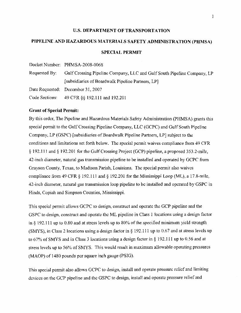
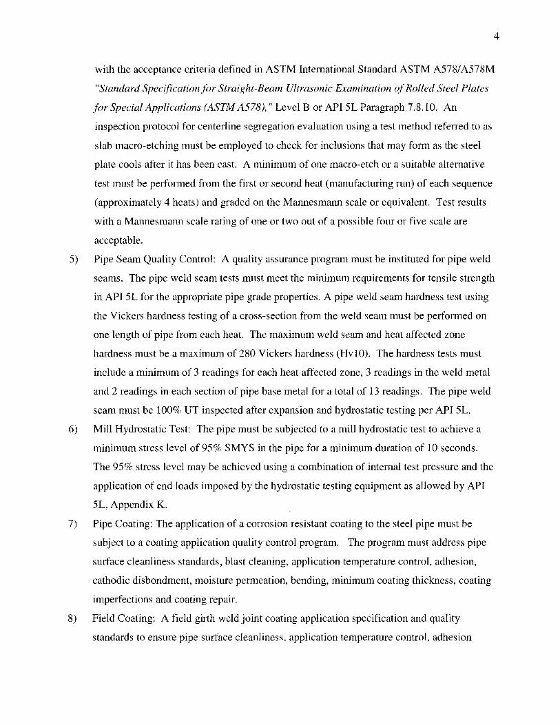