c-series boiler - · pdf file2 c-series boiler installation and operation manual table of...
TRANSCRIPT

1
C-SERIES BOILERINSTALLATION AND OPERATION MANUAL
MODEL #: BURNER MODEL #:
SERIAL #: BURNER SERIAL #:
NATIONAL BOARD #:
DISTRIBUTOR:
National Combustion Co., Inc.104-11 180th StreetJamaica, NY 11433
Ph: 718-291-8400Fx: 718-291-6870
www.nationalcombustion.comemail: [email protected]

2
C-SERIES BOILERINSTALLATION AND OPERATION MANUAL
Table of Contents
General Information 3
Boiler Room / Chimney 4
Dampers / Makeup Air 5
Parts and Installation 6-8
Front Boiler Diagram 9
Rear Boiler Diagram 10
Wiring & Burner Installation 11-12
Filling, Flushing and Maintenance 13-14
Notes on op. pressures & softeners 15
Control of Oxygen Corrosion of Tubes 16-19
Limited Warranty 20
3
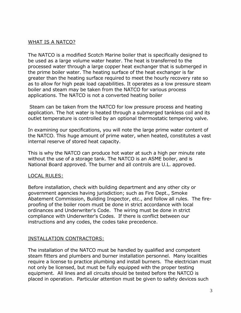
WHAT IS A NATCO?
The NATCO is a modified Scotch Marine boiler that is specifically designed tobe used as a large volume water heater. The heat is transferred to theprocessed water through a large copper heat exchanger that is submerged inthe prime boiler water. The heating surface of the heat exchanger is fargreater than the heating surface required to meet the hourly recovery rate soas to allow for high peak load capabilities. It operates as a low pressure steamboiler and steam may be taken from the NATCO for various processapplications. The NATCO is not a converted heating boiler
Steam can be taken from the NATCO for low pressure process and heatingapplication. The hot water is heated through a submerged tankless coil and itsoutlet temperature is controlled by an optional thermostatic tempering valve.
In examining our specifications, you will note the large prime water content ofthe NATCO. This huge amount of prime water, when heated, constitutes a vastinternal reserve of stored heat capacity.
This is why the NATCO can produce hot water at such a high per minute ratewithout the use of a storage tank. The NATCO is an ASME boiler, and isNational Board approved. The burner and all controls are U.L. approved.
LOCAL RULES:
Before installation, check with building department and any other city orgovernment agencies having jurisdiction; such as Fire Dept., SmokeAbatement Commission, Building Inspector, etc., and follow all rules. The fire-proofing of the boiler room must be done in strict accordance with localordinances and Underwriter's Code. The wiring must be done in strictcompliance with Underwriter's Codes. If there is conflict between ourinstructions and any codes, the codes take precedence.
INSTALLATION CONTRACTORS:
The installation of the NATCO must be handled by qualified and competentsteam fitters and plumbers and burner installation personnel. Many localitiesrequire a license to practice plumbing and install burners. The electrician mustnot only be licensed, but must be fully equipped with the proper testingequipment. All lines and all circuits should be tested before the NATCO isplaced in operation. Particular attention must be given to safety devices such

4
as low-water cutoffs, pressure controls, the safety relief valve, and the flamesafety.BOILER ROOM:
Erect the boiler on a level floor with the burner end of the NATCO as close tothe chimney as is feasible. Perfect installation would require a minimum of 3ft. from the end of the smoke box to the back wall. This will provide adequateroom to properly adjust and service the burner. It is advisable to have anopening at the front of the boiler, so that the coils can be changed. Manycontractors find it convenient to install the entrance door immediately in frontof the NATCO, so the changing or removal of the water coil is no problem.
The boiler room must be constructed air tight with a tight fitting door and itsown ventilation. The air tight room is necessary so if for any reason theproducts of combustion go into the boiler room, the fumes cannot affect theoccupants of the building.
CHIMNEY:
The chimney must be constructed in accordance with all local codes and ifSmoke Abatement rules are applicable, the chimney must be filed with theproper authorities. Forced draft burners require a chimney of the specifieddiameter. Refer to the specification sheets for the internal diameter required.
The chimney must be high enough to prevent the products of combustion fromentering adjacent windows or creating a nuisance for neighbors. It must behigher than adjacent buildings and located where a down draft due to winddirection will not occur.
The vent pipe or breaching must be as short as possible and properlyconnected to the NATCO and the chimney. It must be checked periodically tomake certain that it is tight and has no evidence of any corrosion. IfPerchlorethylene is stored or used in the building, the fumes must beprevented from entering the boiler room, for when Perc is burned, verycorrosive and toxic gases are formed which in addition to being dangerous tohuman life, quickly attack the burner, the boiler and particularly the vent pipeor breaching. The heavier the vent pipe or breaching, the longer it will lastunder normal use and we recommend a minimum of 16 gauge galvanizedsmoke pipe.

5
BAROMETRIC DAMPERS:
Barometric Dampers are helpful for fuel economy when there is negativepressure in the chimney. Forced draft gas burners and oil burners can operatewith a positive pressure in the boilers and unless the chimney is large and tall,negative pressure may not be attained in the breaching. When positivepressure exists in the breaching, a barometric damper does not have anyeffect of the efficiency. and if a barometric damper is used under theseconditions with an oil burner, it may interfere with the start up operation of theoil burner. Barometric dampers used for gas burners must be of the doubleswing type and a spill switch must be provided. This is necessary so that if theproducts of combustion spill into the boiler room, a spill will shut the burneroff. Oil burners when used with barometric dampers are equipped with singleswing blades and therefore require no spill switch.
A barometric damper is not provided with the NATCO and its use, andinstallation must be done under the supervision of a qualified burnerprofessional.
FRESH AIR MAKE-UP:
It is most important that the boiler room be constructed to provide adequatemakeup air. The burning of fuel requires oxygen to support combustion. Thisoxygen must be readily obtainable direct from the outside. It requires onesquare inch opening for every 2,000 BTU input. Since the square inch openingmust be free, if louvers or screens are used, it is best to figure one and one-half times the required opening.
The NATCO should be in a separate room, tightly sealed against the effects ofoil exhaustion due to dryers or exhaust fans. Not only does a dangerouscondition exist if air exhaustion from other equipment places the boiler roomunder a vacuum, but a loss of efficiency and a sooty flame will certainly result.
Rated output can only be expected when the equipment is installed with properfresh air make-up and when the equipment is installed in a boiler room tightlysealed against the effect of air exhaustion of other equipment.
The following tables indicated the sizes of fresh air openings required forvarious NATCO Models.

6
Fresh Air Guidelines, NATCO BoilersNATCO Square Inches Diameter, Single Square InchesModel
# Gas Input, MBTU Oil Input, GPH Total Fresh Air Opening Fresh Air Duct Louvered
C-58 600 4.5 300 10 450C-72 730 5.25 365 11 547.5C-82 850 6 425 12 637.5C-105 1100 8 550 14 825C-130 1400 10 700 15 1050C-165 1700 12 850 17 1275C-200 2100 15 1050 19 1575C-250 2490 19 1245 20 1867.5C-290 3000 22 1500 22 2250C-400 4200 30 2100 26 3150C-500 5200 37 2600 29 3900C-600 6200 44 3100 32 4650
CHECK THE BOILER FOR MISSING OR DAMAGED ITEMS:
The following items come equipped on the boiler:
- Steel jacketing covering a 2” fiberglass jacket.- A burner mounting plate covering a burner refractory donut.- A peep-site assembly.- A front inspection plate insulated by millboard.- A copper heat exchanger with a steel or bronze header.
The following items come in a separate parts box:
- A ½” brass piping assembly including:o A brass pigtailo A brass teeo 2 brass nippleso 1 brass elbowo 1 brass street-elbow
- A ¾” iron piping assembly including:o An iron nippleo An iron teeo 2 iron street-elbows.
- Honeywell PA404A Operating Pressure Control- Honeywell L4079B Manual Reset Pressure Control w/ ½” brass pigtail.

7
- ITT McDonald and Miller PS801-120 Operating Low Water Cutoff- Pressure Gauge- ITT McDonald and Miller PS851M-120 Manual Reset Low Water Cutoff- Gauge Glass & Gauge Cock Assembly- Dial Thermometer- 2 Air Vents
The following items are optional items:
- Tempering Valve- Automatic Water Feeder- Magnesium Anode Rod(s)
ASSEMBLE AND INSTALL COMPONENTS:
1. Assemble and install the air vent assembly. Using Teflon tape ateach connection, attach nipple on center of tee and street-ells onsides of tee. Then install air vents so that they are facing up.Install air vents on assembly first, and then install entireassembly on the ¾” R1 (on diagram) connection on the top ofthe boiler closest to the rear of the boiler (burner mountingside).
2. Cap the steam outlet. If the steam outlet is not being utilized,cap it with a plug of appropriate size.
3. Install pop safety relief valve on R2 on the diagram. We suggestthat you pipe the outlet to the floor or a drain. Do not reducethe outlet piping from the initial size of the relief valveoutlet. For example, if the relief valve has a 2” outlet,your drain-off piping should be 2” diameter.
4. Set Honeywell L4079B to desired redundant secondary highlimit. Usually, this should be set between 12 and 15 PSI. UsingTeflon tape, attach control to a brass pigtail and attach tolocation R3 on the diagram of the rear of the boiler.
5. Set the PA404A operating pressure control setting anddifferential. The setting for the pressure is on the outside of thecontrol. It is important that the setting is lower than the settingfor the L4079B manual reset control. For most applications, setthe cut out to 9 PSI, and the differential to 2 PSI. Thedifferential is set underneath the cover.

8
6. Using Teflon tape at each connection, assemble the ½” brassassembly first before installing. Attach the center outlet of thetee to the end of the brass pigtail. Then attach the nipples tothe brass tee assembly. Attach a street ell to one nipple and anelbow to the other nipple. Attach the pressure control into thestreet-ell, and the pressure gauge to the elbow. Attach theassembly to R4 on the Rear boiler diagram (below).
7. Install the gauge glass assembly with gauge cocks onto the twoconnections indicated by F3 on the front boiler diagram.
8. Install the PS801-120 operating Low-water cutoff at location F2on the front boiler diagram. It is important that the operating(automatic reset) control is installed at the uppermostconnection.
9. Install the PS851M-120 manual reset Low-water cutoff atlocation F1 on the front boiler diagram.

9

10

11
INSTALLING THE BURNER:
The burner must be mounted to the included mounting flange so theincluded burner flange is bolted flush to the mounting flange. Burners mustbe installed, and fired by qualified burner professionals. Burnerprofessionals can pipe fuel according to the instructions in the includedburner installation manual. Professionals shall fire burner and checkrequired readings as required by the included manual.
WIRING THE BOILER/BURNER:
All wiring must be installed by a qualified electrician.
Burners include an “interlock” circuit that allows the boiler controls to havean effect on the firing of the burner. Check the burner installation manual orwiring diagram for the location of this circuit. If you need help locating this,contact NATCO.
There are two ways of wiring the boiler:
Preferred:
1. On the included burner interlock circuit, wire from the burner interlocksupply to (i) the PS801-120, (ii) the PA404A operating control, and(iii) back to the return on the burner interlock.
2. Utilizing an isolation relay so that there is 115V on the control side,and appropriate supply voltage on the other side (depends on theburner), wire the L4079B manual reset pressure control and PS851M-120 Low Water Cutoff in series so that if there is a break in the circuit,no power will be supplied to the burner. Think of this circuit as anautomatic emergency switch to shut off power to the burner.
Alternative:
On the included burner interlock circuit, wire from the burner interlocksupply to the following inseries: (i) the PS851M-120, (ii) the PS801-120,(iii) the L4079B, (iv) the PA404A, and (v) to the burner interlock return.
The first method is preferred, because if the burner interlock fails or is leftjumped through negligence, a dangerous condition cannot result. IF YOUHAVE ANY QUESTIONS PLEASE CONTACT NATCO FOR GUIDANCE.

12
DRAFT AND FURNACE PRESSURE:
The burner included is designed as a forced draft burner capable of supplyingall air for combustion against positive furnace pressure not over 1/2" watercolumn. Furnace pressure must not be positive unless combustion chamber isadequately sealed.
The burner will also operate satisfactorily with conventional stacks andnegative furnace pressures. A barometric draft control should not be usedunless required to overcome excess draft.
Rooms in which burners are located should be provided with adequate airsupply to assure continuous complete combustion. It is recommended thanoutside air openings are provided having a total area not less than 1 squareinch for each 2,000 BTU per hour input. Check local requirements.
GAS PIPING:
The standard gas controls are sized to pass the maximum burner rate with 6"W.C. line pressure ahead of the controls. Valves and regulators are suitable forpressures up to 1/2 pound. Controls are available for higher and lowerpressures.
The installation, checkout and service of the gas burner should be done only bya qualified, competent gas burner mechanic. He must be equipped with fuelanalyzing equipment, gas pressure reading equipment, stack thermometer,and a multimeter.
Gas line should be installed carefully, so that no foreign materials are allowed toenter the gas line; there should be a full size "drip" pipe (or dirt pocket) nearthe burner to trap foreign material. Gas lines should always be tested with airpressure before connecting to the gas supply. Arrange the piping at the burnerso the burner can be moved out for inspection without interference with thegas piping.
All gas piping should be made to highest standards of material andworkmanship in accordance with local codes and ordinances. Where localcodes do not exist, piping should be accordance with American StandardRequirements of Installation of Gas Equipment in Large Boilers (S.A. 221.33)
13
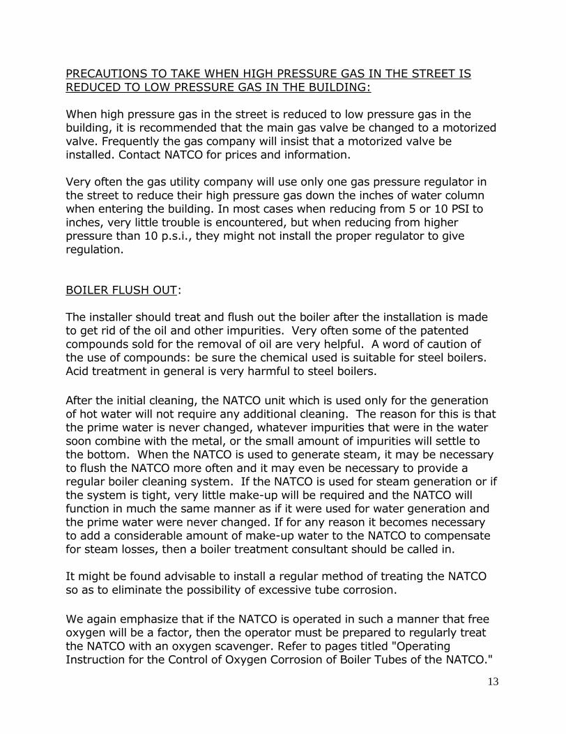
PRECAUTIONS TO TAKE WHEN HIGH PRESSURE GAS IN THE STREET ISREDUCED TO LOW PRESSURE GAS IN THE BUILDING:
When high pressure gas in the street is reduced to low pressure gas in thebuilding, it is recommended that the main gas valve be changed to a motorizedvalve. Frequently the gas company will insist that a motorized valve beinstalled. Contact NATCO for prices and information.
Very often the gas utility company will use only one gas pressure regulator inthe street to reduce their high pressure gas down the inches of water columnwhen entering the building. In most cases when reducing from 5 or 10 PSI toinches, very little trouble is encountered, but when reducing from higherpressure than 10 p.s.i., they might not install the proper regulator to giveregulation.
BOILER FLUSH OUT:
The installer should treat and flush out the boiler after the installation is madeto get rid of the oil and other impurities. Very often some of the patentedcompounds sold for the removal of oil are very helpful. A word of caution ofthe use of compounds: be sure the chemical used is suitable for steel boilers.Acid treatment in general is very harmful to steel boilers.
After the initial cleaning, the NATCO unit which is used only for the generationof hot water will not require any additional cleaning. The reason for this is thatthe prime water is never changed, whatever impurities that were in the watersoon combine with the metal, or the small amount of impurities will settle tothe bottom. When the NATCO is used to generate steam, it may be necessaryto flush the NATCO more often and it may even be necessary to provide aregular boiler cleaning system. If the NATCO is used for steam generation or ifthe system is tight, very little make-up will be required and the NATCO willfunction in much the same manner as if it were used for water generation andthe prime water were never changed. If for any reason it becomes necessaryto add a considerable amount of make-up water to the NATCO to compensatefor steam losses, then a boiler treatment consultant should be called in.
It might be found advisable to install a regular method of treating the NATCOso as to eliminate the possibility of excessive tube corrosion.
We again emphasize that if the NATCO is operated in such a manner that freeoxygen will be a factor, then the operator must be prepared to regularly treatthe NATCO with an oxygen scavenger. Refer to pages titled "OperatingInstruction for the Control of Oxygen Corrosion of Boiler Tubes of the NATCO."

14
CHECK ALL CONNECTIONS AND FILL NATCO WITH WATER:
Be certain that all unused outlets are plugged (NATCO does not supply anyplugs with the boiler) before filling the NATCO. The NATCO must be filled withuntreated water (regular tap water). Never fill the NATCO with softenedwater, which is extremely corrosive. Fill the NATCO unit the water level isabout 1" below the center of the gauge glass.
Adjust the pressure control cut-out point to 9 PSI and the differential to 2 PSI.The burner will then operate between 7 and 9 PSI. The successful operation ofour units depends on storing prime water at 230 degrees or more. It is alsoimportant that as soon as water is drawn, the burner starts on a pressuredrop. For this reason do not install an aquastat to control the burner unlessoperated as a hot water boiler.
AIR VENTS:
The venting of the NATCO is very important for successful operation of theequipment. The purpose of the vent valves is to vent air from the NATCO.When the air vents do not work, the gauge may read 9 lbs. of pressure. If thepressure indicating needle drops in one or two seconds to one pound or less,the boiler is air bound, and both valves may require replacing. If the indicatingneedle drops several pounds and stays at this point for 10 or 15 seconds withthe safety valve open, then the vent valves are working properly.
SERVICE MAINTENANCE:
The burners should only be started up and adjusted by trained competentpersonnel. No electrical service should be done to the burner or controls untilthe main switch is pulled. Never add water to a boiler under pressure. Do notadd water to a hot or overheated boiler. Wait until the boiler cools and thepressure falls to zero. If you cannot see water in the gauge glass and theburner is running, pull the main burner switch at once and wait for the boiler tocool and the pressure to drop to zero before adding water. When this occurs,check the low water cutoff at once and make sure it is functioning correctly. Ifnecessary, have it repaired or replaced immediately. The NATCO must not beoperated unless the low water cutoff is functioning properly.
The entire system must be checked regularly by trained personnel (at leastonce a year) to make certain that the NATCO and all controls and

15
appurtenances and safety devices are working properly. It is very importantthat the safety valve and low water cutoff be checked monthly.
OPERATING PRESSURES:
When the NATCO is operating as a water heater, only set the HoneywellPA404A to cut out at 9 PSI and set the differential to 2 PSI. If additionalreserve is required and the local code permits it, operate between 11 and 13PSI. If the unit is used for low pressure steam drying and water heating, itmight be advantageous to use a large differential. Try setting with 10 lbs. cut-out and a 4 PSI differential. Or, if the code permits, 13 PSI cut-out and a 6 PSIdifferential. Change these settings if local conditions require it. If boiler isshut down at night or on weekends, refer to special boiler treatment toprevent corrosion section in this manual.
WATER SOFTENERS FOR USE IN HARD WATER AREAS:
Water softeners should never be used for filling the steel body of the boilerwith prime water. However, water softeners are very useful for water thatenters the heat exchanger – the heated water.
Hard water precipitates lime scale on the interior surfaces in contact with theheated waters. Hard waters are harmful to every type and design of waterheater, and the NATCO is no exception. When lime scale is formed, thetemperature and volume of the heated water is immediately reduced andeventually, a complete stoppage can take place. This condition is easily andreadily overcome by the installation of a water softener. The water should betested and if the grains hardness is over 10 it is almost certain that watersoftening system should be used. Some waters of less than 10 grainshardness will precipitate an insoluble lime deposit. Check with your local watersupply company.
LOW WATER CUTOFF AND AUTOMATIC WATER FEEDERS:
The NATCO is equipped with a low-water cutoff. The purpose of this cutoff is toautomatically shut down the burner if the water level of the NATCO becomesdangerously low. An automatic water feeder is not supplied as standardequipment and is not recommended unless steam is used for process workand the condensate is not returned. If the system is properly installed and istight, very little make-up water will be needed.

16
NATCO cannot too strongly recommend that the water line of the NATCO bechecked in the water gauge glass daily. It is inadvisable to rely on theautomatic control, for unlessautomatic controls are tested and checked periodically, they might beinoperative when most needed.
If you require an automatic water feeder, please contact NATCO so we cansize an appropriate model for your boiler.
FOR BEST PROTECTION-CHECK THE WATER LINE DAILY
HIGH LIMIT PRESSURE CONTROL:
The New York State Code (and some other states) requires the installation of amanual reset high limit pressure control in addition to the operating pressurecontrol. The purpose of this pressure control is to shut off the burner if theoperating pressure control fails to function. This pressure control requiresmanual resetting to put the burner back in operation. Other localities alsorequire a second pressure control but do not always specify that it must be amanual reset. We now include a L4079B Manual Reset Pressure Control asstandard. We recommend using it.
PROTECTION AGAINST FREEZING IF A SHUT DOWN OCCURS AT FREEZINGTEMPERATURES:
If the NATCO is shut down and there is a danger of freezing, the boiler water inthe NATCO must be drained and the coil must be disconnected, removed fromthe NATCO, and tested on end to drain all the water from the coil and thetempering valve.
OPERATING INSTRUCTIONS FOR THE CONTROL OF OXYGEN CORROSIONON BOILER TUBES OF THE NATCO
Most prime water (the water in the body of the boiler, not entering the heatexchanger) does not require treatment to prevent oxygen corrosion when theNATCO is operated as a water heater and the system is tight. There arecircumstances however, where water is corrosive or where the NATCO must beoperated in such a way as to permit the introduction of oxygen which cancause tube corrosion.

17
While the principle cause of corrosion is due to oxygen in the boiler waterattacking the tubes, there are many variables, and other conditions which cancause corrosion. These exceptional conditions that could cause corrosioninclude carbon dioxide, stray electrical currents coming in from outside, strayelectrical currents because an electric appliance has been grounded to theNATCO, absorption of Perchlorethylene fumes, improper cleaning of the watersurfaces of the boiler, etc.
National Combustion Company does not claim that complying with these ruleswill stop tube corrosion in every case. There are too many variables to contendwith. Wherever possible, we suggest that a specialist be called in to make ananalysis of the condition and submit a schedule for the regular treatment ofthe boiler to protect against oxygen corrosion.
The following are a few simple instructions that, if conscientiously followed, willprotect the NATCO against tube corrosion in the vast majority of cases:
A. The NATCO is used as a water heater only and constant steam pressureis maintained. Very little make-up water is required.
The NATCO must be filled with unsoftened water. If a water softener isused, a tap water connection must be made to fill line of the NATCO.The prime water must never be changed. The prime water (boilerwater) should be treated with caustic soda, commercially sold as lye(sodium hydroxide, NaOH), to raise the pH to 11.5. We recommend 3oz. of caustic soda per 100 gallons prime water of boiler water contentof the NATCO (20 grams per 100 liters). Refer to NATCO specificationsheet for the prime water content of the NATCO.
B. The NATCO is used as a water heater, but the steam pressure is reducedto zero at nights or over long weekends. This also applies when theNATCO is used for hot water and to provide steam for steam dryers orother equipment where the condensate is returned.
1. Add 3 oz. of caustic soda (lye) per 100 gallons regardless of theoriginal pH of the water.
2. Should the grains of hardness in the water be below 3 (50 ppm),add 1-1/2 oz. of sodium sulphate (Na2So3) per 100 gallons ofprime water (10 grams per 100 liters). Add sodium sulphate atleast four times a year. Sodium sulphate is an excellent andinexpensive oxygen scavenger. It is good practice to obtain asodium sulphate tester and maintain a concentration of 100 ppm.
3. A Magnesium Anode Rod can be used as oxygen scavenger as well.One rod should be used per each 300 gallons of prime water in the

18
boiler (check the specification sheet for the total number ofgallons of prime water).
C. The NATCO is used as a steam generator and the steam is not returnedto the NATCO. For example, steam is used for baker ovens, TurkishBaths, cookers in dry cleaning Plants, steam for concrete aggregate, etc.Provisions must be made to automatically compensate for the lostcondensate, but in addition to this oxygen corrosion must be guardedagainst.
1. Add 3 oz. of caustic soda (lye) per 100 gallons of prime water.2. 2. Add 1-1/2 oz. of sodium sulphate per 100 gallons of prime water
and maintain the level of 100 ppm. Check with a sodium sulphatetester.
3. Use Magnesium Anode Rods. One rod should be used per each 300gallons of prime water in the boiler (check the specification sheet forthe total number of gallons of prime water).
CAUSTIC SODA CAN BE OBTAINED IN A SUPERMARKET UNDER THECOMMERCIALNAME OF "LYE".
Note: Samples of tap water may be sent to NATCO for analysis and advice.
PROPER CARE OF IDLE BOILERS:
If a NATCO is to remain idle, such as a seasonal shutdown, the boiler must becared for properly. Water readily absorbs oxygen during a shutdown. An idleboiler must be completely filled with alkaline water (pH between 11 and 11.5)and containing 100 ppm Sodium Sulphate (1-1/2 oz. per 100 gallons of primewater). We recommend that the safety valve be removed and a nipple 8" longbe installed. Add water until it overflows.
Before again placing the NATCO in operation, surface blow the boiler understeam pressure for about 5 minutes, then drain the water and refill with freshtap water. Add caustic soda and sodium sulphate as required. (Refer topreceding paragraphs)
Also test the steam pressure safety valve and clean and test the low-watercutoffs.
19
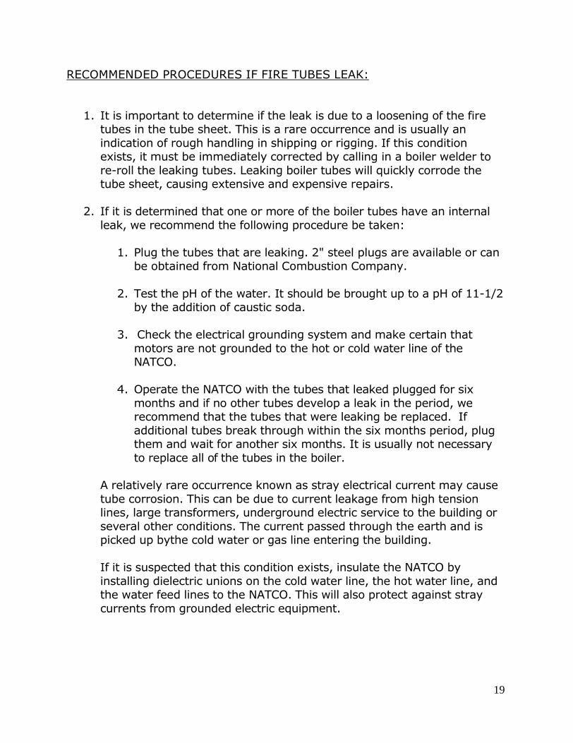
RECOMMENDED PROCEDURES IF FIRE TUBES LEAK:
1. It is important to determine if the leak is due to a loosening of the firetubes in the tube sheet. This is a rare occurrence and is usually anindication of rough handling in shipping or rigging. If this conditionexists, it must be immediately corrected by calling in a boiler welder tore-roll the leaking tubes. Leaking boiler tubes will quickly corrode thetube sheet, causing extensive and expensive repairs.
2. If it is determined that one or more of the boiler tubes have an internalleak, we recommend the following procedure be taken:
1. Plug the tubes that are leaking. 2" steel plugs are available or canbe obtained from National Combustion Company.
2. Test the pH of the water. It should be brought up to a pH of 11-1/2by the addition of caustic soda.
3. Check the electrical grounding system and make certain thatmotors are not grounded to the hot or cold water line of theNATCO.
4. Operate the NATCO with the tubes that leaked plugged for sixmonths and if no other tubes develop a leak in the period, werecommend that the tubes that were leaking be replaced. Ifadditional tubes break through within the six months period, plugthem and wait for another six months. It is usually not necessaryto replace all of the tubes in the boiler.
A relatively rare occurrence known as stray electrical current may causetube corrosion. This can be due to current leakage from high tensionlines, large transformers, underground electric service to the building orseveral other conditions. The current passed through the earth and ispicked up bythe cold water or gas line entering the building.
If it is suspected that this condition exists, insulate the NATCO byinstalling dielectric unions on the cold water line, the hot water line, andthe water feed lines to the NATCO. This will also protect against straycurrents from grounded electric equipment.

20
Limited Warranty
For Natco Tankless “ C-Series and M-Series”
National Combustion Co.,Inc. ("NATCO") sells the NATCO Water Heater, the NATCO Boiler usedfor both process work and heating, and combination hot water and steam units. The principalpart of the system is the steam pressure vessel. The "pressure vessel" is constructed inaccordance with ASME low pressure boiler code and it is so stamped. It carries the NationalBoard serial number. The vessel is hydrostatically tested after construction at sixty poundsper square inch by the ASME inspector and a certificate to this effect is furnished with the"pressure vessel". NATCO agrees to repair leaks in the pressure vessel (known as the shellonly) developing within One year from the date of installation. There will be no charge for laboror services. However, NATCO will not repair leaks: (1) developing in gaskets, (2) in externalthreads due to the installer's faulty workmanship, (3) due to misuse or abuse, (4) due toexcessive lime formation, (5) caused by oxygen by corrosion of the boiler tubes, or (6) due toconditions beyond the control of NATCO.
Leaks must be promptly reported. NATCO is not responsible for related damage caused by theleak.
We reserve the right to inspect the pressure vessel and access must be provided during normalworking hours. If we authorize repairs to the pressure vessel, they will be made only duringnormal working hours. NATCO will not be responsible for any repairs made to the pressurevessel that were made without its written authorization.
NATCO may furnish, in conjunction with the NATCO heater, various appurtenances such asburner, coils, pumps, controls, etc. NATCO warrants to the original purchaser such equipmentto be free from defects in material and workmanship under normal use and service. Ourobligation under this warranty shall be limited to the repair or exchange, F.O.B., New York Cityof any part or parts returned to us at customer's expense, which may prove defective undernormal use and service within one year from date of installation and which our examinationshall disclose to our satisfaction to be thus defective.
Equipment which is repaired or replaced shall carry a warranty equal to the unexpired portionof the original warranty. THIS WARRANTY IS EXPRESSLY IN LIEU OF ALL OTHER WARRANTIESEXPRESSED OR IMPLIED INCLUDING THE WARRANTIES OR MERCHANTABILITY AND FITNESSFOR USE AND OF ALL OTHER OBLIGATIONS OR LIABILITIES ON OUR PART, AND WE NEITHERASSUME, NOR AUTHORIZE ANY OTHER PERSON TO ASSUME FOR US, ANY OTHER LIABILITY INCONNECTION WITH PRODUCTS SOLD BY NATCO ("EQUIPMENT"). THIS WARRANTY SHALL NOTAPPLY TO EQUIPMENT OR ANY PART THEREOF WHICH HAS BEEN SUBJECT TO ACCIDENT,NEGLIGENCE, ALTERATION, ABUSE OR MISUSE. WE MAKE NO WARRANTY WHATSOEVER INRESPECT TO ACCESSORIES OF PARTS NOT SUPPLIED BY US. THE TERM "ORIGINALPURCHASER", AS USED IN THIS WARRANTY, SHALL BE DEEMED TO MEAN THAT PERSON ORFIRM FOR WHOM EQUIPMENT IS ORIGINALLY INSTALLED.
Defects caused by improper installation, operation, handling or acts beyond our control are notcovered.
NATCO will not be responsible for any service except as set forth herein. The purchaserexpressly waives all damages whether direct, incidental, or consequential.
Where applicable, refer to the Installation Manual for details of installation and operation.