c series water softeners - rainfreshrainfresh.ca/wp/wp-content/uploads/2016/05/product...c series...
TRANSCRIPT

C Series Water Softeners Installation & Operation Manual (Please save for future reference)
Thank you for purchasing one of our ENVIROGARD / Rainfresh Water Softeners. We are committed to ensuring that you are totally satisfied.
If you have any problems, don’t go back to the store – please contact us !
Most issues can be resolved over the phone. Help Line : 1-800-667-8072 (Monday to Friday 8:30 AM to 5:00 PM EST)
www.rainfresh.ca
TABLE OF CONTENTS
A. System Specifications ............................................. 2 B. How Your Water Conditioner Works ...................... 2 C. Safety Precautions & Cautions ............................... 2 D. Installation ............................................................. 3
a. Electrical Requirements ............................... 4 b. Unpacking the unit ....................................... 4 c. Plumbing the Softener ................................. 4
E. Start-up and Programming .................................... 6 a. Level 1 Programming .................................. 7 b. Level 2 Programming .................................. 10 c. Manual Regeneration .................................. 12
F. Other Features ...................................................... 12 G. Maintenance .......................................................... 12 H. Troubleshooting ..................................................... 13 I. Exploded Diagram & Parts List ............................... 14 J. Warranty ................................................................ 16
Certified by IAPMO R&T against CSA B483.1 and NSF/ ANSI 44.
2
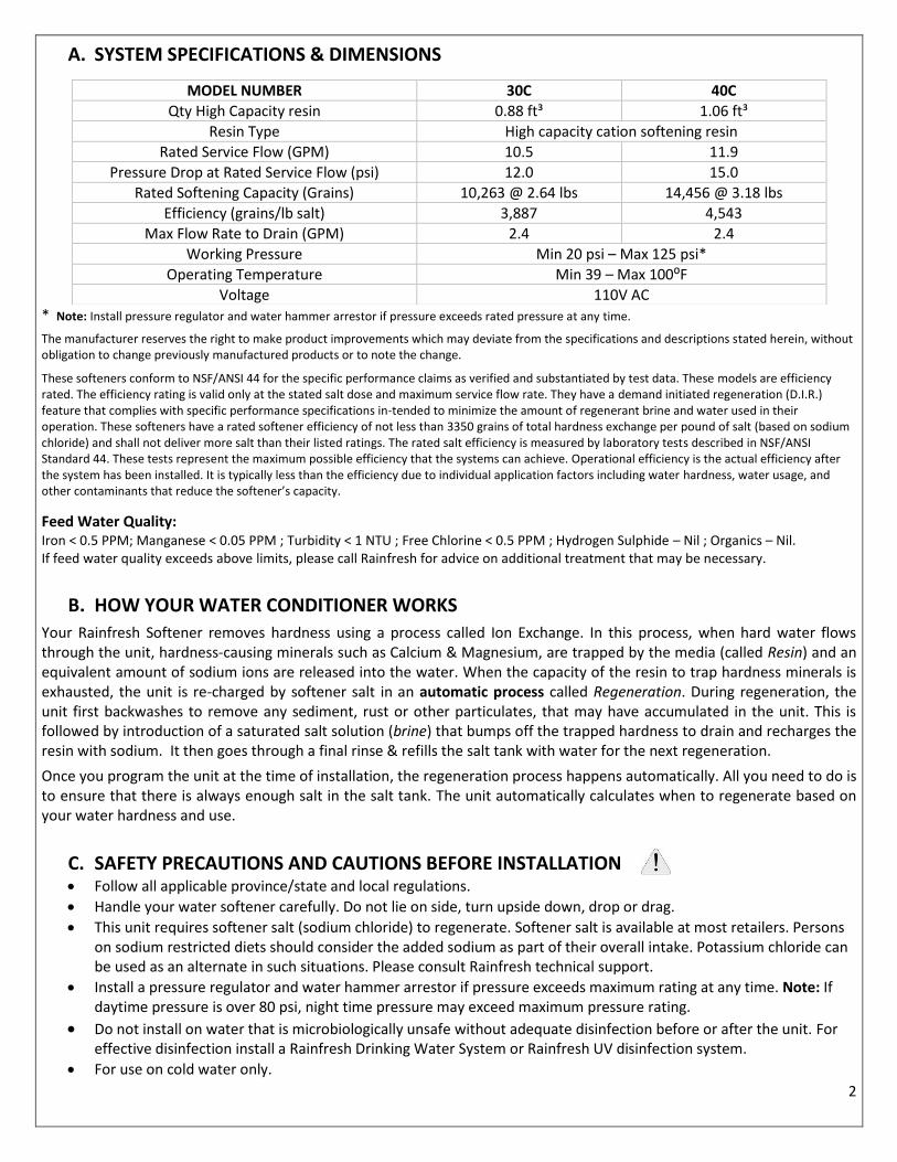
A. SYSTEM SPECIFICATIONS & DIMENSIONS
* Note: Install pressure regulator and water hammer arrestor if pressure exceeds rated pressure at any time.
The manufacturer reserves the right to make product improvements which may deviate from the specifications and descriptions stated herein, without obligation to change previously manufactured products or to note the change.
These softeners conform to NSF/ANSI 44 for the specific performance claims as verified and substantiated by test data. These models are efficiency rated. The efficiency rating is valid only at the stated salt dose and maximum service flow rate. They have a demand initiated regeneration (D.I.R.) feature that complies with specific performance specifications in-tended to minimize the amount of regenerant brine and water used in their operation. These softeners have a rated softener efficiency of not less than 3350 grains of total hardness exchange per pound of salt (based on sodium chloride) and shall not deliver more salt than their listed ratings. The rated salt efficiency is measured by laboratory tests described in NSF/ANSI Standard 44. These tests represent the maximum possible efficiency that the systems can achieve. Operational efficiency is the actual efficiency after the system has been installed. It is typically less than the efficiency due to individual application factors including water hardness, water usage, and other contaminants that reduce the softener’s capacity.
Feed Water Quality: Iron < 0.5 PPM; Manganese < 0.05 PPM ; Turbidity < 1 NTU ; Free Chlorine < 0.5 PPM ; Hydrogen Sulphide – Nil ; Organics – Nil. If feed water quality exceeds above limits, please call Rainfresh for advice on additional treatment that may be necessary.
B. HOW YOUR WATER CONDITIONER WORKS
Your Rainfresh Softener removes hardness using a process called Ion Exchange. In this process, when hard water flows through the unit, hardness-causing minerals such as Calcium & Magnesium, are trapped by the media (called Resin) and an equivalent amount of sodium ions are released into the water. When the capacity of the resin to trap hardness minerals is exhausted, the unit is re-charged by softener salt in an automatic process called Regeneration. During regeneration, the unit first backwashes to remove any sediment, rust or other particulates, that may have accumulated in the unit. This is followed by introduction of a saturated salt solution (brine) that bumps off the trapped hardness to drain and recharges the resin with sodium. It then goes through a final rinse & refills the salt tank with water for the next regeneration.
Once you program the unit at the time of installation, the regeneration process happens automatically. All you need to do is to ensure that there is always enough salt in the salt tank. The unit automatically calculates when to regenerate based on your water hardness and use.
C. SAFETY PRECAUTIONS AND CAUTIONS BEFORE INSTALLATION Follow all applicable province/state and local regulations.
Handle your water softener carefully. Do not lie on side, turn upside down, drop or drag.
This unit requires softener salt (sodium chloride) to regenerate. Softener salt is available at most retailers. Persons on sodium restricted diets should consider the added sodium as part of their overall intake. Potassium chloride can be used as an alternate in such situations. Please consult Rainfresh technical support.
Install a pressure regulator and water hammer arrestor if pressure exceeds maximum rating at any time. Note: If daytime pressure is over 80 psi, night time pressure may exceed maximum pressure rating.
Do not install on water that is microbiologically unsafe without adequate disinfection before or after the unit. For effective disinfection install a Rainfresh Drinking Water System or Rainfresh UV disinfection system.
For use on cold water only.
MODEL NUMBER 30C 40C
Qty High Capacity resin 0.88 ft³ 1.06 ft³
Resin Type High capacity cation softening resin
Rated Service Flow (GPM) 10.5 11.9
Pressure Drop at Rated Service Flow (psi) 12.0 15.0
Rated Softening Capacity (Grains) 10,263 @ 2.64 lbs 14,456 @ 3.18 lbs
Efficiency (grains/lb salt) 3,887 4,543
Max Flow Rate to Drain (GPM) 2.4 2.4
Working Pressure Min 20 psi – Max 125 psi*
Operating Temperature Min 39 – Max 100⁰F
Voltage 110V AC

3
Only use thread seal tape (Teflon® tape) for fitting connections into unit. DO NOT USE pipe dope or chemical sealants.
If water pipes are used to ground electrical system, install jumper wire (#4 gauge solid copper wire) across the unit to maintain proper grounding of your electrical system
Protect your unit from freezing - drain the unit if freezing temperatures exist.
NOTE: IF SOLDER TYPE FITTINGS ARE USED DO NOT USE torch near inlet/outlet connections. All solder joints should be made before joining pipe to filter head. Use only lead-free solder and flux.
DO NOT over-tighten metal fittings on to unit connections.
Place the unit on a flat level surface. Do not place shims under the unit to level it. The weight of the unit full of water and salt can cause the cabinet to crack at the shim.
The unit should only be moved by 2 or more people due to heavy weight. Failure to do so can result in injury.
The unit must be installed in an area where there is reasonable access to the salt tank for regular salt filling.
D. INSTALLATION
Electrical Requirements: The automatic control valve requires a constant power supply - 110V AC. We recommend a GFI (ground fault
interrupter) outlet within 5 feet of the softener. Extension cords are not recommended.
If water pipes are used to ground electrical system, you will need to install a jumper wire across the filter unit.
Unpacking the unit The unit includes:
Unpack the unit and discard the plastic air pack inside the unit. Place the unit at the location where you intend to install it.
Stand back and look at the softener to make sure it is standing straight up and not tilted to one side. Make sure your chosen location will be fairly level, dry, and protected from possible freezing conditions. The softener can sit directly on the floor and will not corrode. DO NOT set the softener onto make shift platforms as this can damage the salt tank, or may cause it to topple.
The system has 3 connections - an inlet, an outlet, and a drain line connection. If you are looking at the back of the unit (fig 1), the inlet is on the left side. Warning: Make sure that you have correctly identified the inlet of the system. REVERSING THE CONNECTIONS WILL RESULT IN RESIN BEADS BEING THROWN INTO YOUR HOME'S PLUMBING SYSTEM CAUSING DAMAGE TO IT AS WELL AS THE SOFTENER.
The following pipe can be used for installing your new system - Copper, CPVC, and PEX are the most popular.
1) Softener with built-in salt tank and bypass valve
2) Inlet/outlet elbow fittings (2)
– ¾” Male NPT
3) Allen key (for ease of opening & closing bypass valve)
4) Brine overflow fitting
5) Drain hose (15 ft) with hose clamp
6) AC power adapter

4
Installation Location Installation location for city (municipally treated) water Installation location for well water
Plumbing in your softener
If your hot water tank is electric, turn off the power to it to avoid damage to the element in the tank.
If you have a private well, turn the power off to the pump then shut off the main water shut off valve. If you have municipal water, simply shut off the main valve. Go to a faucet, (preferably on the lowest floor of the house) turn on the cold water until all pressure is relieved and the flow of water stops.

5
Position the softener in the desired location. The unit comes with two 90° ¾” male NPT elbow fittings (see fig 1). You can rotate them at any angle to suit your installation. Make sure that the bypass valve is in bypass mode as shown in fig 2.
Note: To change the connection fitting, simply remove the locking clips by hand and pull the fitting out. Insert new fitting and reinstall locking clip (fig 3).
Plumb in the softener using appropriate fittings.
Unscrew the cabinet top using a screwdriver and move the top aside, making sure that the electronic cable underneath does not detach from the circuit board.
Attach the drain hose (15 ft included) to the drain fitting and secure it with a hose clamp (fig 4) (included).
Run the drain line to a nearby laundry tub, standing pipe or floor drain (fig 5) and cut off excess tubing.
NOTE ABOUT DRAIN LINE : You can run the drain hose from the unit to the ceiling joists (max 8 ft ceiling) and run it to the nearest laundry tub or drain pipe. This can be run up overhead or down along the floor. Use band clamps to hold the drain tubing in place. If running drain line more than 15 feet from the softener (max 25 ft), increasing the line size to 3/4" will be required. Please follow your local plumbing & other applicable codes for where to run softener discharge water. NEVER MAKE A DIRECT CONNECTION INTO A WASTE WATER DRAIN. A PHYSICAL AIR GAP OF AT LEAST 1.5" SHOULD BE USED TO AVOID BACTERIA AND WASTEWATER TRAVELING BACK THROUGH THE DRAIN LINE INTO THE SOFTENER (see fig 5). If you have other water conditioners, such as an iron filter, carbon filter, tannin filter etc., RUN THE DRAIN TUBING FOR EACH UNIT SEPARATELY. DO NOT TEE (COMBINE) DRAIN TUBING FROM OTHER UNITS.
You can also use code-approved air-gap attachments available at most plumbing stores.
Attaching the overflow tubing: If the overflow fitting is not pre-attached to the cabinet, then drill a ¾” hole on the side of the softener about ¾ of the way from the bottom (fig 6). Insert the over flow fitting from the outside and tighten the nut from the inside to lock it.
Attach the rest of the drain tubing to the overflow fitting and run to the floor drain with an appropriate air gap, as shown in fig 5. If you do not have any more drain tubing left, you will need to purchase extra tubing at your local plumbing retailer. WARNING : DO NOT TEE THE OVERFLOW TUBING TO THE DRAIN TUBING
Re-attach the cabinet top and secure it with the screws.
Fig 5
LAUNDRY TUB STANDING PIPE FLOOR DRAIN OR SUMP
Min 1.5” air gap
Min 1.5” air gap
Min 1.5” air gap
Fig 2
Fig 3
Fig 4
Fig 6

6
The salt tank is pre-connected to the control head. Lift the cabinet lid and add about 5 gallons of water in the salt tank. This is not a critical level but just helps with the process for the first regeneration. Then add 2 bags (20 Kg bags) of salt to start with. DO NOT ADD MORE THAN 2 BAGS OF SALT to prevent salt bridging.
Turn main house shut-off valve on slightly and watch for leaks. Ensure a faucet is on somewhere and that its aerator is removed to avoid clogging from loosened scale in the pipes. If you have no leaks, proceed to the next steps.
Turn on the water supply
Using the Allen key (included), turn the bypass inlet slightly (refer to fig 2) to allow water to run into the unit. The water should initially fill the tank slowly. Once the tank is full of water, you can open valve fully. This prevents resin from being pushed up into the control head by the initial surge of water going in.
Make sure there are no leaks in your plumbing before proceeding. At the nearest cold treated water tap remove the faucet screen and open the faucet.
Using the Allen key (included), open the outlet side of the bypass valve and let water run a few minutes or until the system is free of any air or foreign material resulting from the plumbing work. Close the water tap when water runs clean, and then proceed to start up instructions.
Connect the control valve to the power adapter (fig 7) & connect the adapter to the power supply.
NOTE: Your unit is not yet ready for service until you complete manual regeneration (see pages 7-11)
E. START UP & PROGRAMMING
The control valve is controlled with simple, user-friendly electronics displayed on an LCD screen.
When power is first supplied, the valve electronics may take up to two minutes to initialize. During this time the screen will show “INTIALIZING WAIT PLEASE”. Do not touch any buttons at this time. When the valve reaches the service position, it will display the following information in sequence:
1. Date & Time 2. Capacity (gal of water that can be used between
regenerations) 3. Volume Remaining (gal of water left before regeneration
begins)
4. Regeneration Time (Time of day when regeneration starts) 5. Last Regeneration Date (Last date when system regenerated) 6. Current Flow Rate (GPM) (flow rate of water being currently
used) 7. Peak Flow Rate (GPM) (Max recorded flow rate of the water)
The control valve has a display screen and 4 buttons
MENU BUTTON The function of this key is to enter the level one programming mode where the valve settings can be adjusted.
SET / REGEN BUTTON This button has two functions. The first is to initiate a manual regeneration by holding the button for 3 or more seconds. The second function is while in programming mode, pressing this key allows the user to change the value of each setting.
UP / DOWN These buttons are used to increase or decrease the value of the settings while in the programming mode.
FOR VIDEO INSTRUCTIONS ON PROGRAMMING
Scan QR code
or visit
http://rainfresh.ca/how_to_videos.php#program
Fig 7

7
PROGRAMMING YOUR WATER SOFTENER The valve has 2 levels of programming – Level 1 and Level 2 You will need to only go through Level 1 programming to start up your unit. Level 2 programming is factory set and can be changed only if desired. In level 1 programming you can set current time, date, number of people in your home and the feed water hardness. Level 1 programming is completed in 5 easy steps.
Level 1 PROGRAMMING STEP 1 : Set Current Time
1. Press MENU for 3 seconds
5. Press SET/REGEN once and the highlighted value flashes
6. Now press UP or DOWN key to change the hour values to current time
7. Press SET/REGEN again. Hour value will be accepted and minute value will start flashing
2. The display will read “Press MENU Key for 3 sec to unlock”.
3. After 3 seconds, the display will beep confirming unlock
4. Press MENU again and the hour value becomes highlighted
PRESS MENU KEY
3 SEC TO UNLOCK
CURRENT TIME
05 : 27 PM
CURRENT TIME
05 : 27 PM
CURRENT TIME
07 : 27 PM CURRENT TIME
07 : 27 PM
CURRENT TIME
07 : 45 PM
8. Now press UP or DOWN key to change the minute value to current time
CURRENT TIME
07 : 45 PM
9. Press SET/REGEN again. Minute value will be accepted and AM/PM value will start flashing
10. Now press UP or DOWN key to change the value to AM or PM
CURRENT TIME
07 : 45 AM
CURRENT TIME
07 : 45 AM
11. Press SET/REGEN again to accept. Flashing stops & hour value is highlighted again. PROCEED TO STEP 2
JAN/21/2018
05:27 PM
8
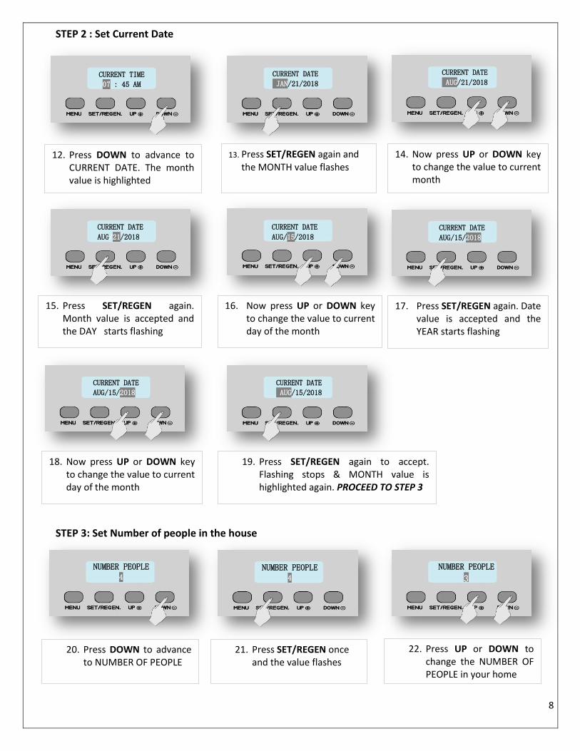
STEP 2 : Set Current Date
STEP 3: Set Number of people in the house
13. Press SET/REGEN again and the MONTH value flashes
15. Press SET/REGEN again. Month value is accepted and the DAY starts flashing
CURRENT TIME
07 : 45 AM
12. Press DOWN to advance to CURRENT DATE. The month value is highlighted
CURRENT DATE
JAN/21/2018
CURRENT DATE
AUG/21/2018
14. Now press UP or DOWN key to change the value to current month
CURRENT DATE
AUG/21/2018
CURRENT DATE
AUG/15/2018
16. Now press UP or DOWN key to change the value to current day of the month
CURRENT DATE
AUG/15/2018
17. Press SET/REGEN again. Date value is accepted and the YEAR starts flashing
CURRENT DATE
AUG/15/2018
18. Now press UP or DOWN key to change the value to current day of the month
NUMBER PEOPLE 4
19. Press SET/REGEN again to accept. Flashing stops & MONTH value is highlighted again. PROCEED TO STEP 3
CURRENT DATE
AUG/15/2018
20. Press DOWN to advance to NUMBER OF PEOPLE
NUMBER PEOPLE 4
NUMBER PEOPLE
3
21. Press SET/REGEN once and the value flashes
22. Press UP or DOWN to change the NUMBER OF PEOPLE in your home

9
STEP 4: Setting Water Hardness
This value is the hardness value of your water in grains per gallon (GPG). If you have the reading in PPM or mg/L, simply divide that by 17.1 to get the reading in GPG. You must also add (5 x iron level in PPM) to the hardness value.
HARDNESS VALUE = YOUR WATER HARDNESS + (5 x Iron concentration in PPM) For example, if your water hardness is 20 GPG and the iron level is 0.3 PPM, the hardness value you enter must be
20 + 5 x (0.3) = 20 + 1.5 = 21.5 GPG Note: If you do not know your water hardness, please call customer service for details on how to send us a water
sample and receive a free water analysis. In the meantime, you can leave the hardness value at default setting. You can also visit www.rainfresh.ca for details.
STEP 5: Setting Vacation Mode This function may be activated during a prolonged absence, such as a vacation for more than 2 weeks. The system will perform a brief backwash and rinse based on advanced setting. The purpose is to keep the water fresh in the softener tank and plumbing system. When you return from vacation, return the holiday mode to "NO".
YOUR UNIT IS NOW READY FOR SERVICE
23. Press SET/REGEN again to accept the value. Highlight stops flashing
26. Now press UP or DOWN keys to set feed water hardness & press SET/REGEN again to accept
NUMBER PEOPLE
3 WATER HARDNESS
20 GPG
25. Press SET/REGEN again. HARDNESS value starts flashing
WATER HARDNESS
15 GPG VACATION MODE
YES NO
27. Now press DOWN key to advance to VACATION MODE. Press DOWN again to exit or press SET/REGEN to set vacation mode
24. Press DOWN to advance to WATER HARDNESS. The value is highlighted. PROCEED TO STEP 4
WATER HARDNESS
20 GPG
Press the DOWN button to enter the holiday mode setting.
Press SET / REGEN to flash the display.
Press the UP or DOWN buttons to select YES or NO.
Press SET / REGEN again to confirm the setting.
The display stops blinking. Press MENU to
exit level 1 programming.

10
Level 2 PROGRAMMING (OPTIONAL SETTINGS)
NOTE : Under normal use there is no need to change the settings under level 2 programming. You can, however, change the default settings if required. CAUTION: DO NOT CHANGE LEVEL 2 SETTINGS WITHOUT CONSULTING RAINFRESH TECHNICIAN (1-800-667 8072). Wrongly changing the settings can result in malfunction of the unit. When the Level 2 Master Programming Mode is entered, all available option setting displays may be viewed and set as needed. Depending on current option settings, some parameters cannot be viewed or set.
To change any setting under level 2 programming
- press the SET/REGEN key and the value flashes - press the UP or DOWN keys to change the value - press the SET/REGEN key again to accept value - press the DOWN key to advance to the next value
The following chart indicates choices and default settings. Note: Default settings are indicated in bold letters Use same programming method as you used in level 1 to advance and/or change values.
Bold letters indicate default settings
Parameter Option 1 Option 2 Option 3 Option 4 Comments
1 System Language English Spanish French Set to French if desired. Spanish not enabled
2 Valve Operation Softener Filter Iron
Filter Leave at default setting
3 Regeneration Mode
Meter Delayed
Meter Override
Calendar Clock
Meter Immediate
Leave at default setting
4 Regeneration Time 2:00 AM The unit is factory set to regenerate at 2:00 AM on the day of regeneration. You can change to another time if desired.
5 Capacity Calculation
Automatic Manual Automatic (recommended). Change to manual settings if desired.
6 Resin Volume For model 30C, set resin volume at 0.88 cu ft For model 40C set resin volume at 1.06 cu ft
7 Salt Setting Leave at default setting for maximum efficiency. (Defaults – 6 lbs/ft³) Note: Capacity = Amount of water that can be softened between regenerations. Capacity reduces when salt setting is reduced, but salt consumption efficiency increases.
1. Press MENU for 3 seconds to unlock screen.
JAN/21/2015
05:27 PM
2. The display will read “Press MENU Key for 3 sec to unlock”.
3. After 3 seconds, the display will beep confirming unlock
PRESS MENU KEY
3 SEC TO UNLOCK
SYSTEM LANGUAGE
ENGLISH
4. Press and hold UP & DOWN keys together for three seconds to enter Level Two Master Programming.

11
Salt Setting (lbs/cu ft)*
Model 2.0 2.5 3.0 4.5 6.0 8.0 10.0 12.0 15.0
30C 0.9 1.0 1.3 1.9 2.5 3.4 4.2 5.0 6.3
40C 1.0 1.3 1.5 2.3 3.0 4.0 5.0 6.0 7.5
Table 1 : Refill time (in minutes) for various salt settings using Sodium Chloride
* Salt settings not validated by IAPMO
Disinfecting the Softener It is possible that during shipping, storage & installing, bacteria can go into the unit. Therefore, as a good installation practice, it is recommended that the softener be disinfected prior to use. To disinfect, open the lid of the brine well in the salt tank and add approx. 3 tablespoons of fresh common household bleach. Replace lid & proceed to next step. Manual Regeneration If screen is locked, press MENU key for 3 seconds to unlock. To initiate an immediate regeneration, press the SET/REGEN button for 3 seconds, an option for “Delayed” or “Immediate” regeneration will appear. Press the SET/REGEN button again and “Delayed” will begin flashing. Now press the down arrow button and “Immediate” will flash. Press the SET/REGEN button once and then press the menu button once. Valve will immediately start manual regeneration. YOUR UNIT IS NOW READY FOR SERVICE
F. OTHER FEATURES
Control Operation During a Power Failure In the event of a power failure, the valve will keep track of the time and day for 48 hours. The programmed settings are stored in a non-volatile memory and will not be lost during a power failure. If power fails while the unit is in regeneration, the valve will finish regeneration after power is restored. If the valve misses a scheduled regeneration due to a power failure, it will queue regeneration at the next regeneration time once power is restored.
Safety Float The brine tank is equipped with a safety float which prevents your brine tank from overfilling as a result of a malfunction such as a power failure.
New Sounds You may notice new sounds as your water softener operates. The regeneration cycle lasts approximately 2 hours. During this time, you may hear water running intermittently to the drain.
8 Refill Flow Rate 0.7 GPM Leave at default setting
9 Unit Capacity For 30C unit, set at 33,000 grains if you chose 15 lbs salt/ft³ otherwise leave at default For 40C unit, set at 40,000 grains if you chose 15 lbs salt/ft³ otherwise leave at default
10 Reserve Capacity 75
gal/person Increase or decrease value as desired
11 Capacity This will be the calculated unit capacity in US Gal. The unit will regenerate only when this much water has been used.
12 Backwash 05 Increase to 10 if water has lot of dirt or rust
13 Brine / Rinse 50 Increase to 60 if water is more than 15 grains hard
14 Rapid Rinse 5 Increase to 10 if you want a longer rinse time after regeneration
15 Refill For REFILL settings based on your chosen salt settings, please refer to Table 1 below
16 Restore Default NO Leave at default. Change only if you would like to re-start programming from the beginning
Open this lid & pour bleach inside
12
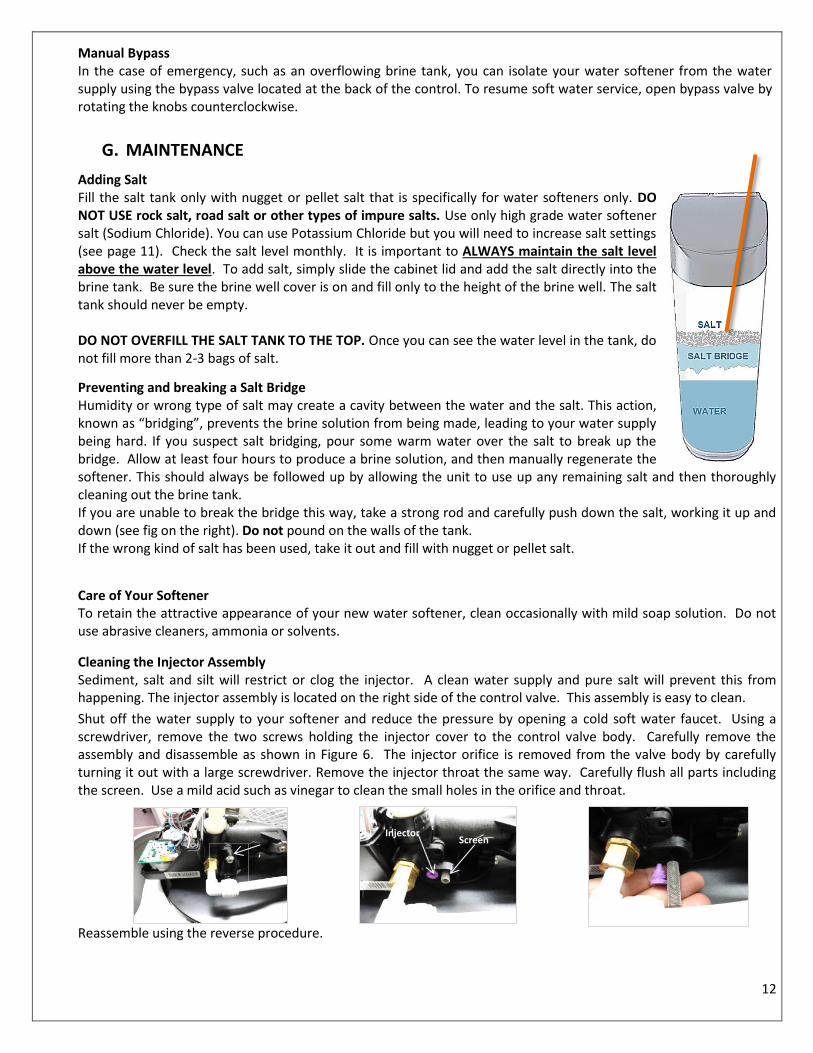
Manual Bypass In the case of emergency, such as an overflowing brine tank, you can isolate your water softener from the water supply using the bypass valve located at the back of the control. To resume soft water service, open bypass valve by rotating the knobs counterclockwise.
G. MAINTENANCE
Adding Salt Fill the salt tank only with nugget or pellet salt that is specifically for water softeners only. DO NOT USE rock salt, road salt or other types of impure salts. Use only high grade water softener salt (Sodium Chloride). You can use Potassium Chloride but you will need to increase salt settings (see page 11). Check the salt level monthly. It is important to ALWAYS maintain the salt level above the water level. To add salt, simply slide the cabinet lid and add the salt directly into the brine tank. Be sure the brine well cover is on and fill only to the height of the brine well. The salt tank should never be empty. DO NOT OVERFILL THE SALT TANK TO THE TOP. Once you can see the water level in the tank, do not fill more than 2-3 bags of salt.
Preventing and breaking a Salt Bridge Humidity or wrong type of salt may create a cavity between the water and the salt. This action, known as “bridging”, prevents the brine solution from being made, leading to your water supply being hard. If you suspect salt bridging, pour some warm water over the salt to break up the bridge. Allow at least four hours to produce a brine solution, and then manually regenerate the softener. This should always be followed up by allowing the unit to use up any remaining salt and then thoroughly cleaning out the brine tank. If you are unable to break the bridge this way, take a strong rod and carefully push down the salt, working it up and down (see fig on the right). Do not pound on the walls of the tank. If the wrong kind of salt has been used, take it out and fill with nugget or pellet salt.
Care of Your Softener To retain the attractive appearance of your new water softener, clean occasionally with mild soap solution. Do not use abrasive cleaners, ammonia or solvents.
Cleaning the Injector Assembly Sediment, salt and silt will restrict or clog the injector. A clean water supply and pure salt will prevent this from happening. The injector assembly is located on the right side of the control valve. This assembly is easy to clean.
Shut off the water supply to your softener and reduce the pressure by opening a cold soft water faucet. Using a screwdriver, remove the two screws holding the injector cover to the control valve body. Carefully remove the assembly and disassemble as shown in Figure 6. The injector orifice is removed from the valve body by carefully turning it out with a large screwdriver. Remove the injector throat the same way. Carefully flush all parts including the screen. Use a mild acid such as vinegar to clean the small holes in the orifice and throat. Reassemble using the reverse procedure.
Injector Screen
13
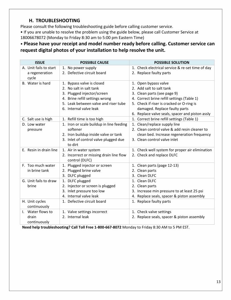
H. TROUBLESHOOTING
Please consult the following troubleshooting guide before calling customer service. • If you are unable to resolve the problem using the guide below, please call Customer Service at 18006678072 (Monday to Friday 8:30 am to 5:00 pm Eastern Time)
• Please have your receipt and model number ready before calling. Customer service can request digital photos of your installation to help resolve the unit.
ISSUE POSSIBLE CAUSE POSSIBLE SOLUTION
A. Unit fails to start a regeneration cycle
1. No power supply 2. Defective circuit board
1. Check electrical service & re-set time of day 2. Replace faulty parts
B. Water is hard 1. Bypass valve is closed 2. No salt in salt tank 3. Plugged injector/screen 4. Brine refill settings wrong 5. Leak between valve and riser tube 6. Internal valve leak
1. Open bypass valve 2. Add salt to salt tank 3. Clean parts (see page 9) 4. Correct brine refill settings (Table 1) 5. Check if riser is cracked or O-ring is
damaged. Replace faulty parts 6. Replace valve seals, spacer and piston assly
C. Salt use is high 1. Refill time is too high 1. Correct brine refill settings (Table 1)
D. Low water pressure
1. Iron or scale buildup in line feeding softener
2. Iron buildup inside valve or tank 3. Inlet of control valve plugged due
to dirt
1. Clean/replace supply line 2. Clean control valve & add resin cleaner to
clean bed. Increase regeneration frequency 3. Clean control valve inlet
E. Resin in drain line 1. Air in water system 2. Incorrect or missing drain line flow
control (DLFC)
1. Check well system for proper air elimination 2. Check and replace DLFC
F. Too much water in brine tank
1. Plugged injector or screen 2. Plugged brine valve 3. DLFC plugged
1. Clean parts (page 12-13) 2. Clean parts 3. Clean DLFC
G. Unit fails to draw brine
1. DLFC plugged 2. Injector or screen is plugged 3. Inlet pressure too low 4. Internal valve leak
1. Clean DLFC 2. Clean parts 3. Increase min pressure to at least 25 psi 4. Replace seals, spacer & piston assembly
H. Unit cycles continuously
1. Defective circuit board 1. Replace faulty parts
I. Water flows to drain continuously
1. Valve settings incorrect 2. Internal leak
1. Check valve settings 2. Replace seals, spacer & piston assembly
Need help troubleshooting? Call Toll Free 1-800-667-8072 Monday to Friday 8:30 AM to 5 PM EST.

14
I. PARTS LIST
Item No. Part No. Description Quantity
A01 05056087 Screw - M5x12 (Hexagon) 3
A02 05056088 Screw - M5x16 (Hexagon with washer) 2
A03 05056047 End plug retainer 1
A04 05030002 Piston rod 1
A05 05056097 Piston pin 1
A06 05056023 End plug 1
A07 05056070 Quad ring 2
A08 05056024 End plug washer 1
A09 05056022 Piston retainer 1
A10 05056181 Piston (electrical) 1
A11 05056104 Muffler 1
A12 05056021 Spacer 4
A13 05056073 Seal 5
A14 05030001 Valve body 1
A15 05056129 O-ring φ 23x3 4
A16 05056025 Adaper coupling 2
A17 05056044 Adaptor clip 2
A18 05056090 Screw-ST4. 2x13 (Hexagon with washer) 2

15
A19 21709003 Secure clip 2
A20 05056140 Valve connector 1
A21 05056065 O-ring φ 23.6x2.65 2
A22 21319006 Screw adaptor 2
A23 05056508 Screw M5x12 (Hexagon with washer) 5
A24 05030004 End cover 1
A25 05030013 O-ring φ 30x2.65 1
A26 13000426 Screw-ST2. 9x13 (Large) 2
A27 07060007 Valve bottom connector 1
A28 26010103 O-ring φ 25x3.55 1
A29 05056063 O-ring φ 78.74x5.33 1
A30 05056086 Screw - M5x30 (Hexagon with washer) 2
A31 05056029 Injector cover 1
A32 05056072 O-ring φ 24x2 1
A33 05056027 Injector nozzle 1
A34 05056103 Injector screen 1
A35 05056028 Injector throat 1
A36 05056035 BLFC button retainer 1
A37 05056191 BLFC - 2# 1
A38 05056138 O-ring φ 14x1.8 1
A39 05056100B BLFC fitting 1
A40 05056106 Brine line screen 1
A41 05056107 BLFC tube insert 1
A56 Drain line flow control (DLFC) 1
12
To order replacement parts: Call 1800 667 8072 Monday to Friday
8:00 AM to 5 PM EST.
DESCRIPTION
1 Control Valve Display Module
2 Top distributor
3 Riser
4 Media Tank for model 30C – 9”x 35
Media Tank for model 40C – 10”x 35
5 Softener resin
6 Cabinet
7 Cabinet top cover
8 Brine safety float
9 Brine Well
10 Salt (not included)
11 Bottom Distributor
12 Power adapter (110V)

16
J. Limited Warranty
This “C” Series Softener System is warranted to the original Consumer purchaser for a period of one (1) year, from the date of purchase, against defects in materials or workmanship. The electronic controls and mineral tank are warranted for 5 and 10 years respectively against defects in materials or workmanship. The company's obligation under this warranty shall consist of repair or replacement, at its option, of any part found by company inspection to be defective, provided that the product has not been misused, abuse, altered or damaged by Consumer with respect to the original installation, as determined by the company. This warranty will not apply if water passing through the System has a) Turbidity / Suspended Solids > 5 ppm (mg/l). b) Hydrogen Sulphide concentrations greater than 0.05 ppm (0.05 mg/l). c) Iron concentration greater than 0.5 ppm (0.5 mg/l) or Manganese greater than 0.05 ppm (0.05 mg/l), f) Tannins or colour. This limited Warranty applies only to a unit when returned to the Warrantor at the owner’s expense and in accordance with shipping instructions received from the Warrantor. This warranty does NOT cover, and is intended to exclude, any liability on the part of Envirogard for any incidental damages, consequential damages, labour charges or any other costs incurred in connection with the purchase, installation, use, maintenance or repair of the system whether under this warranty or any other warranty implied by law. Some provinces/states do not allow the exclusion of incidental or consequential damages, so the above limitation or exclusion may not apply to you. This warranty gives you specific legal rights and you may also have other rights, which vary from province/state to province/state. This warranty applies only to softeners purchased in Canada or the U.S.A.
Envirogard Products Limited 446 Major Mackenzie Drive East,
Richmond Hill, ON L4C 1J2, Canada Tel : (905) 884 9388 Helpline: 1800 667 8072
Web: www.rainfresh.ca
Apr
il 20
18