c: trianglemanuals440440 ma - signodeacme.com · distributed by: cgxa585852 (800) 788-0830 for...
TRANSCRIPT

DISTRIBUTED BY:
CGXA585852
(800) 788-0830
FOR PARTS AND SERVICE
PHONE: 800-523-4904FAX: 800-788-2606
Revision B - 12/27/2007
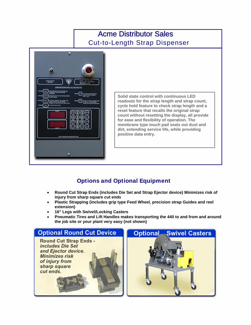
Solid state control with continuous LED readouts for the strap length and strap count, cycle hold feature to check strap length and a reset feature that recalls the original strap count without resetting the display, all provide for ease and flexibility of operation. The membrane type touch pad seals out dust and dirt, extending service life, while providing positive data entry.
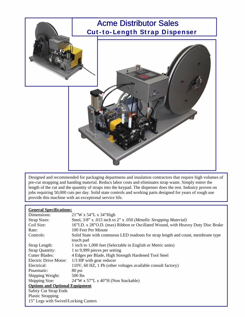
Acme Distributor Sales Cut-to-Length Strap Dispenser
Options and Optional Equipment
• Round Cut Strap Ends (includes Die Set and Strap Ejector device) Minimizes risk ofinjury from sharp square cut ends
• Plastic Strapping (includes grip type Feed Wheel, precision strap Guides and reelextension)
• 16" Legs with Swivel/Locking Casters• Pneumatic Tires and Lift Handles makes transporting the 440 to and from and around
the job site or your plant very easy (not shown)
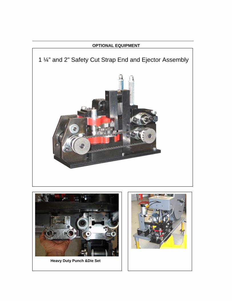
OPTIONAL EQUIPMENT
1 ¼” and 2” Safety Cut Strap End and Ejector Assembly
Heavy Duty Punch &Die Set
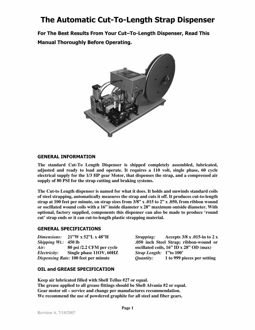
The Automatic Cut-To-Length Strap Dispenser
Page 1 Revision A, 7/18/2007
For The Best Results From Your Cut–To-Length Dispenser, Read This
Manual Thoroughly Before Operating.
GENERAL INFORMATION
The standard Cut-To Length Dispenser is shipped completely assembled, lubricated,
adjusted and ready to load and operate. It requires a 110 volt, single phase, 60 cycle
electrical supply for the 1/3 HP gear Motor, that dispenses the strap, and a compressed air
supply of 80 PSI for the strap cutting and braking systems.
The Cut-to Length dispenser is named for what it does. It holds and unwinds standard coils
of steel strapping, automatically measures the strap and cuts it off. It produces cut-to-length
strap at 100 feet per minute, on strap sizes from 3/8” x .015 to 2” x .050, from ribbon wound
or oscillated wound coils with a 16” inside diameter x 28” maximum outside diameter. With
optional, factory supplied, components this dispenser can also be made to produce ‘round
cut’ strap ends or it can cut-to-length plastic strapping material.
GENERAL SPECIFICATIONS
Dimensions: 21”W x 52”L x 48”H
Shipping Wt.: 450 lb
Air: 80 psi /2.2 CFM per cycle
Electricity: Single phase 11OV, 60HZ
Dispensing Rate: 100 feet per minute
Strapping: Accepts 3/8 x .015-in to 2 x
.050 inch Steel Strap; ribbon-wound or
oscillated coils, 16” ID x 28” OD (max)
Strap Length: 1”to 100’
Quantity: 1 to 999 pieces per setting
OIL and GREASE SPECIFICATION Keep air lubricated filled with Shell Tellus #27 or equal.
The grease applied to all grease fittings should be Shell Alvania #2 or equal.
Gear motor oil – service and change per manufactures recommendation.
We recommend the use of powdered graphite for all steel and fiber gears.
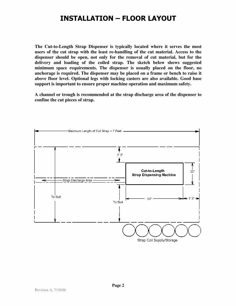
INSTALLATION – FLOOR LAYOUT
Page 2 Revision A, 7/18/06
The Cut-to-Length Strap Dispenser is typically located where it serves the most
users of the cut strap with the least re-handling of the cut material. Access to the
dispenser should be open, not only for the removal of cut material, but for the
delivery and loading of the coiled strap. The sketch below shows suggested
minimum space requirements. The dispenser is usually placed on the floor, no
anchorage is required. The dispenser may be placed on a frame or bench to raise it
above floor level. Optional legs with locking casters are also available. Good base
support is important to ensure proper machine operation and maximum safety.
A channel or trough is recommended at the strap discharge area of the dispenser to
confine the cut pieces of strap.

INSTALLATION - ADJUSTMENTS
4) Adjust the Guide Roller Assemblys by removing and reposistioning the rollers into the appropriate holes to match the strap width being used.
3) Set the regulator at 80 P.S.I. for all strap sizes. Fill Lubricator and adjust for one (1) drop of oil every 5 to 6 cuts/cycles. Check filter daily.
2) Connect the air line to the filter, regulator, lubricator.
1) Insert the electrical plug into a 110 volt, single phase, 60 hertz, alternating current outlet. Any other voltage will damge the equipment.
5) Adjust the Fixed Disc of the strapping reel for ribon wound coils of 3/4” and 1 1/4” strap. Place the spacers between the hub on the reel shaft and the back side of the fixed disc. Use the 5/8”spacers for 3/4” wide strap and the 3/8” spacer for 1 1/4” wide strap. No adjustment is required for 2” wide strap or osilated wound coils of 3/8” to 3/4” steel strapping.
7) Adjust the Curverd Guard (not shown). Lossen the four bolts at its base and center the guard between the two reel discs.Retighten bolts at base.
6) Adjust the Removable Disc of the strapping reel. Remove the disc, adjust the posistion of the two Jam Nuts to suit the width of the strap coil (see figure 2).
FIXED DISC
REMOVABLE DISC
JAM NUTS -SEE NOTE 6
SPACERS -SEE NOTE 5
WING NUT
SPACERS -STORAGE LOCATION
HUB
REVISION B : 8/1/2007 Page 3
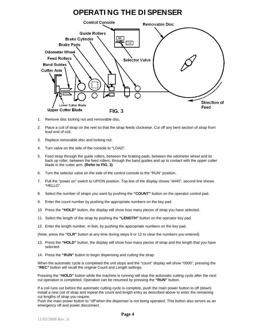
OPERATING THE DISPENSER
1. Remove disc locking nut and removable disc.
2. Place a coil of strap on the reel so that the strap feeds clockwise. Cut off any bent section of strap fromlead end of coil.
3. Replace removable disc and locking nut.
4. Turn valve on the side of the console to “LOAD”.
5. Feed strap through the guide rollers, between the braking pads, between the odometer wheel and itsback up roller, between the feed rollers, through the band guides and up to contact with the upper cutterblade in the cutter arm. (Refer to FIG. 3)
6. Turn the selector valve on the side of the control console to the “RUN” position.
7. Pull the “power on” switch to UP/ON position. Top line of the display shows “d440”, second line shows“HELLO”.
8. Select the number of straps you want by pushing the “COUNT” button on the operator control pad.
9. Enter the count number by pushing the appropriate numbers on the key pad.
10. Press the “HOLD” button, the display will show how many pieces of strap you have selected.
11. Select the length of the strap by pushing the “LENGTH” button on the operator key pad.
12. Enter the length number, in feet, by pushing the appropriate numbers on the key pad.
(Note, press the “CLR” button at any time during steps 9 or 12 to clear the numbers you entered)
13. Press the “HOLD” button, the display will show how many pieces of strap and the length that you haveselected.
14. Press the “RUN” button to begin dispensing and cutting the strap.
When the automatic cycle is completed the unit stops and the “count” display will show “0000”, pressing the “REC” button will recall the original Count and Length settings.
Pressing the “HOLD” button while the machine is running will stop the automatic cutting cycle after the next cut operation is completed. Operation can be resumed by pressing the “RUN” button.
If a coil runs out before the automatic cutting cycle is complete, push the main power button to off (down) Install a new coil of strap and repeat the count and length entry as described above to enter the remaining cut lengths of strap you require. Push the main power button to “off“when the dispenser is not being operated. This button also serves as an emergency off and power disconnect.
Page 4 11/03/2008 Rev. A
MAINTENANCE CLEANING AND MAINTENANCE OF THE 440 EQUIPMENT • Frequently blow off the entire machine with clean, dry, compressed air. As a minimum, it is
recommended that this be done at the beginning and or end of every shift. Particular attention should be paid to the guide roller and feed and cutter head assemblies, the strap path through the machine.
• Scrape the feed rollers or use mineral spirits to clear any build up wax that may accumulate
on them. • Lubricate the two drive gear grease fittings on the Feed and Cutter Head assembly every two
weeks. • Lubricate the two grease fittings in the reel stand every 6 months. • Change the gear motor oil after the first two weeks of operation. Thereafter, change the oil in
the gear box every six months. Use Mobil type SHC-634 oil or equivalent.
ADJUSTMENTS IN ADDITION TO THE REEL SPACERS AND THE GUIDE ROLLERS THERE ARE TWO OTHER ADJUSTMENTS:
1. Feed Roller Tension – adjust by means of the lock nuts over the die springs.
2. Air Pressure.
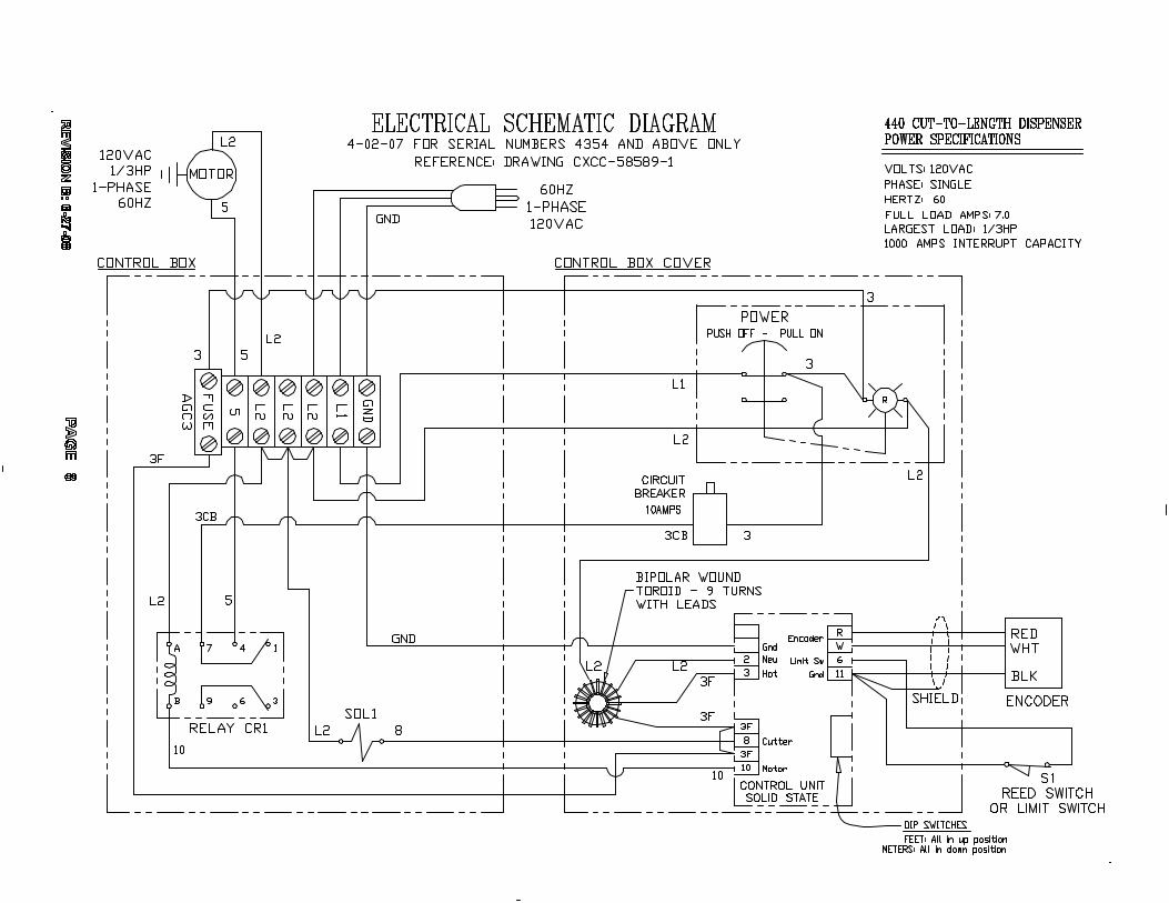
Important Note: Control Unit IN THE EVENT OF A MALFUNCTION OR BREAKDOWN OF THE CIRCUIT BOARD/CONTROL UNIT, DO NOT ATTEMPT TO REPAIR THE BOARD OR THE OLDER CONTROL UNITS. • For machines that have the current solid state control board (see page 5a, FIG.1), for warranty
issues, disconnect the board only and return to the factory for replacement/repair. • For machines that have the old style solid state control board (see page 5a, FIG.2), remove
the entire top of the control box, disconnect and tag each wire, and return the entire top to the factory for repair.
• For machines that have the old style electro/mechanical controls (see page 5a, FIG.3) consult
with factory for complete information to retro fit the new solid state controls.
Page 5

CONTROL UNIT IDENTIFICATION
Current Control Box Cover and Solid State Control Board.
Approx. S/N 4201 and Higher (See Note)
Operators View Back View
FIG.1
Note: Many machines with Serial Numbers below 4201 have been converted to the current solid state control board shown above.
Page 5A
Control Box Cover with Electro/Mechanical Controls
S/N 3569 and Below
Operators View Back View
FIG.3
Control Box Cover and Old Solid State Control Board.
S/N 3570 to @4200
Operators View Back View
FIG.2
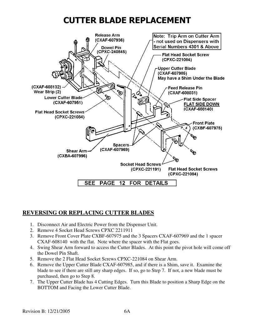
CUTTER BLADE REPLACEMENT
Revision B: 12/21/2005 6A
REVERSING OR REPLACING CUTTER BLADES
1. Disconnect Air and Electric Power from the Dispenser Unit.
2. Remove 4 Socket Head Screws CPXC 2211911
3. Remove Front Cover Plate CXBF-607975 and the 3 Spacers CXAF-607969 and the 1 spacer
CXAF-608140 with the flat. Note where the spacer with the Flat goes.
4. Swing Shear Arm forward to access the Cutter Blades. At this point the pivot hole will come off
the Dowel Pin Shaft.
5. Remove the 2 Flat Head Socket Screws CPXC-221084 on Shear Arm.
6. Remove the Upper Cutter Blade CXAF-607985, and if there is a Shim, save it. Examine the
blade to see if there are still any sharp edges. If so, go to Step 7. If not, a new blade must be
purchased, then go to Step 8.
7. The Upper Cutter Blade has 4 Cutting Edges. Turn this Blade to position a Sharp Edge on the
BOTTOM and Facing the Lower Cutter Blade.
CUTTER BLADE REPLACEMENT
Revision B: 12/21/2005 6B
8. Insert Upper Cutter Blade into the pocket on the Shear Arm with the existing Shim behind the
Blade, and then fasten with the Flat Head Socket Screws. Tighten the Screws securely.
9. Remove the 2 Flat Head Socket Screws CPXC-221084 holding the Lower Cutter Blade.
10. Remove Lower Cutter Blade CXAF-607951 and examine to see if there are still any sharp edges.
If so, go to Step 11. If not, a new blade must be purchased, then go to Step 12.
11. The Lower Cutter Blade also has 4 Cutting Edges. Turn this Blade to position a Sharp Edge on
the TOP and Facing the Upper Cutter Blade.
12. Insert Lower Cutter Blade into the Notches on the Feed and Cutter Frame Side Plates, then fasten
with the Flat Head Socket Screws. Tighten the Screws securely.
13. Re-Assemble:
• Swing the Shear Arm back so that the Cutter Blades are against each other and fit the
pivot hole onto the Dowel Pin Shaft.
• NOTE: Be sure to Place the Feed Release Pin CXAF-608033 on the top of the
Release Arm CXAF-607936
• Re-mount the Spacers and Cover Plate with the Socket Head Screws.
• NOTE: The Flat Side Spacer CXAF-608140 goes on TOP and nearest the pivot hole,
with the FLAT SIDE DOWN – Rotate the Shear Arm UP against the Spacers flat to
make sure that the arm can be raised to its maximum, then tighten the Screw at thisSpacer.
• Tighten the other 3 Screws securely.
CHECKING THE GAP
G1. If either of the Cutter Blades is new, their thickness may be slightly different from the old
Blade. If so, the Gap between the Upper and Lower Cutter Blades may also be different.
• The Gap between the Upper and Lower Cutter blades should be between 0.0025” and
0.0035” for proper cutting (0.0020” and 0.0030” for Stainless Steel). Check this with a
Feeler Gauge.
G2. If the Gap is not within this range, the Upper Blade must be removed again and a new Shim of
the appropriate thickness will have to be used.
G3. If the Gap is too small, use a THINNER Shim. If the Gap is too large, use a THICKER Shim.
G4. Re-Assemble per Step 13 above and re-check the Gap.
G5. Repeat Steps G1 through G4 until the Gap is within the appropriate range.
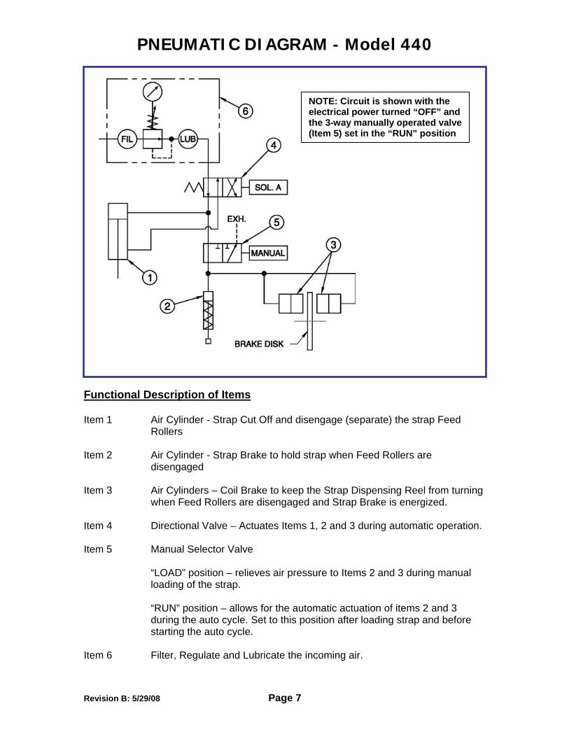
PNEUMATIC DIAGRAM - Model 440
NOTE: Circuit is shown with the electrical power turned “OFF” and the 3-way manually operated valve (Item 5) set in the “RUN” position
Functional Description of Items
Item 1 Air Cylinder - Strap Cut Off and disengage (separate) the strap Feed Rollers
Item 2 Air Cylinder - Strap Brake to hold strap when Feed Rollers are
disengaged
Item 3 Air Cylinders – Coil Brake to keep the Strap Dispensing Reel from turning when Feed Rollers are disengaged and Strap Brake is energized.
Item 4 Directional Valve – Actuates Items 1, 2 and 3 during automatic operation.
Item 5 Manual Selector Valve
“LOAD” position – relieves air pressure to Items 2 and 3 during manual loading of the strap. “RUN” position – allows for the automatic actuation of items 2 and 3 during the auto cycle. Set to this position after loading strap and before starting the auto cycle.
Item 6 Filter, Regulate and Lubricate the incoming air.
Revision B: 5/29/08 Page 7
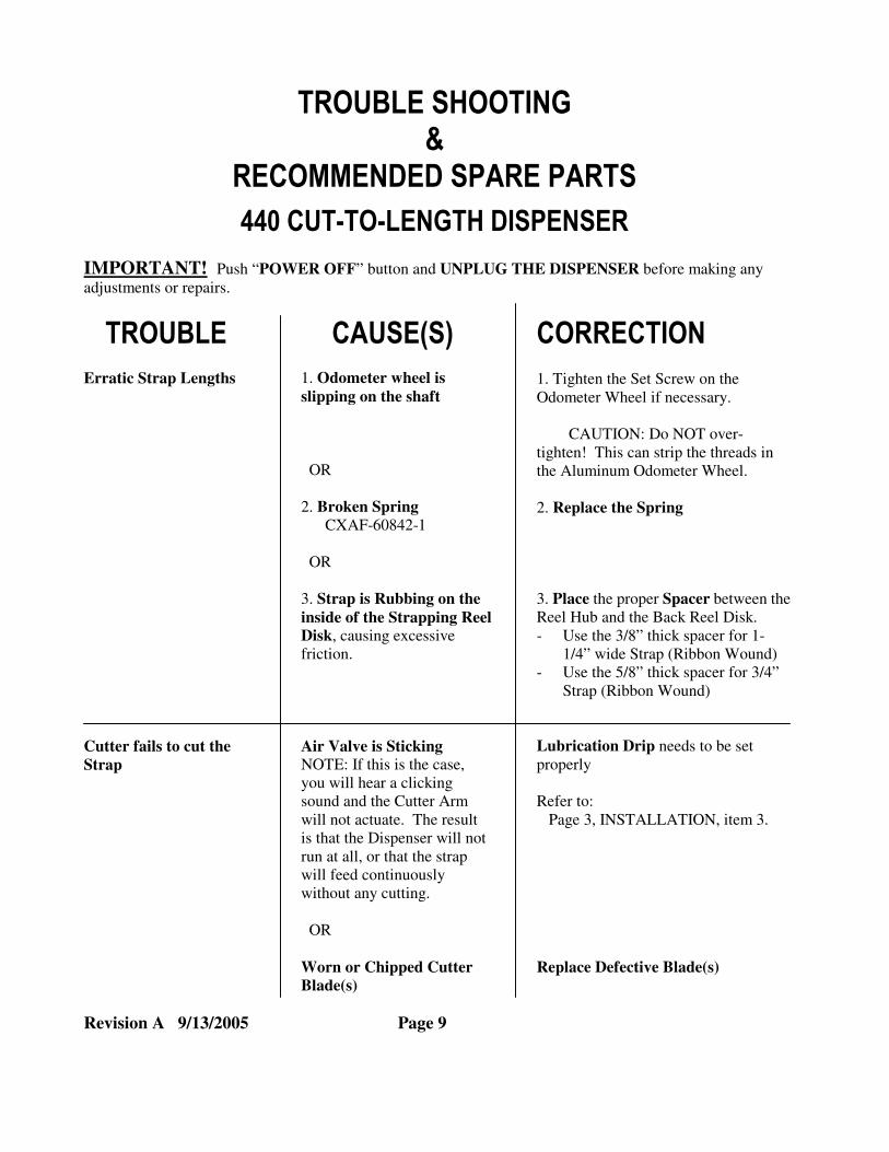
TROUBLE SHOOTING &
RECOMMENDED SPARE PARTS
440 CUT-TO-LENGTH DISPENSER
IMPORTANT! Push “POWER OFF” button and UNPLUG THE DISPENSER before making any
adjustments or repairs.
TROUBLE
Erratic Strap Lengths
CAUSE(S)
1. Odometer wheel is
slipping on the shaft
OR
2. Broken Spring
CXAF-60842-1
OR
CORRECTION
1. Tighten the Set Screw on the
Odometer Wheel if necessary.
CAUTION: Do NOT over-
tighten! This can strip the threads in
the Aluminum Odometer Wheel.
2. Replace the Spring
3. Strap is Rubbing on the
inside of the Strapping Reel Disk, causing excessive
friction.
3. Place the proper Spacer between the
Reel Hub and the Back Reel Disk.
- Use the 3/8” thick spacer for 1-
1/4” wide Strap (Ribbon Wound)
- Use the 5/8” thick spacer for 3/4”
Strap (Ribbon Wound)
Cutter fails to cut the
Strap
Air Valve is Sticking NOTE: If this is the case,
you will hear a clicking
sound and the Cutter Arm
will not actuate. The result
is that the Dispenser will not
run at all, or that the strap
will feed continuously
without any cutting.
OR
Worn or Chipped Cutter
Blade(s)
Lubrication Drip needs to be set
properly
Refer to:
Page 3, INSTALLATION, item 3.
Replace Defective Blade(s)
Revision A 9/13/2005 Page 9

TROUBLE SHOOTING - continued
TROUBLE
Single cycling – Cuts only ONE piece of
Strap at a time,
regardless of setting
CAUSE(S)
1. Broken Reed Switch **
(S/N 4301 & Above) OR
2. Control Unit Malfunction
OR
3. Broken Switch Roller
Arm **
(S/N 4300 & Below)
CORRECTION
1. Replace Reed Switch **
2. Check for Loose wiring.
- Tighten loose wires
- If none, Replace Control Unit
3. Replace Switch Roller Arm **
Machine Fails to Feed
Strap
1. Feed Rollers are Loose
(not enough Roller pressure
between them to Feed the
Strap)
OR
2. Excess wax on Feed Rollers
1. Tighten the Spring Pressure
- Loosen the Top Hex Nut on
top of each Spring
- Turn the Lower Hex Nut
Clockwise as required
- Using two wrenches, tighten
the Top Hex Nut against the
Lower Hex Nut
2. Clean the Wax off the Feed Rollers
- Thoroughly Wire Brush both
Feed Rollers
- Blow off debris with
Compressed Air
** For Units with Serial Numbers before 4298, a Limit Switch (CPXC-45085-7) was used with a
modified Limit Switch Arm (CXAF-60876-9). For these C-T-L Units, with the POWER ON and
programmed for several cuts, trip the Arm manually to see if the Limit Switch is operational at
all; if it signals the Unit to cycle again, the Limit Switch is okay. If it is not okay, UNPLUG the
Dispenser, then replace the Limit Switch (re-use the Limit Switch Arm). If the Limit Switch is
operational, with the POWER ON, CAREFULLY re-adjust the Arm position on the Limit Switch
shaft to trigger JUST (within 1/16” to 1/8”) before the Cutter Arm is fully DOWN.
RECOMMENDED SPARE PARTS
Although the 440 is designed for long, trouble-free operation, certain parts of your Cut-To-Length Dispenser
will wear out with use and will require replacement from time to time. It is recommended that you keep the
following parts in stock at your plant, in order to minimize down time.
QUANTITY PART NUMBER PART NAME 2 CXAF-60842-1 Spring
1 CXAF-60798-5 Cutter Blade - Upper
1 CXAF-60795-1 Cutter Blade - Lower
2 CPAC-60785-5 Spring
1 CPAC-60803-3 Pin – Feed Release
1 CXAF-60837-1 Upper Pad – Band Brake
1 CXAF-60838-9 Lower Pad – Band Brake
Revision A 9/13/2005 Page 10


AA
Designed and recommended for packaging departmens and insulation contractors that require high volumes of pre-cut strapping and banding material. Reducs labor costs and eliminates strap waste. Simply entrer the length of the cut and the quantity of straps into the keypad. The dispenser does the rest. Industry proven on jobs requiring 50,000 cuts per day. Solid state controls and working parts designed for years of rough use provide this machine with an exceptional service life.
Acme Distributor Sales Cut-to-Length Strap Dispenser
General Specifications: Dimensions: 21”W x 54”L x 34”High Strap Sizes: Steel, 3/8” x .015 inch to 2” x .050 (Metallic Strapping Material) Coil Size: 16”I.D. x 28”O.D. (max) Ribbon or Oscillated Wound, with Heavey Duty Disc Brake Rate: 100 Feet Per Minute Controls: Solid State with contnuous LED readouts for strap length and count, membrane type
touch pad Strap Length: 1 inch to 1,000 feet (Selectable in English or Metric units) Strap Quantity: 1 to 9,999 pieces per setting Cutter Blades: 4 Edges per Blade, High Strength Hardened Tool Steel Electric Drive Motor: 1/3 HP with gear reducer Electrical: 110V, 60 HZ, 1 Ph (other voltages available consult factory) Pnuematic: 80 psi Shipping Weight: 500 lbs Shipping Size: 24”W x 57”L x 40”H (Non Stackable) Options and Optional Equipment Safety Cut Strap Ends Plastic Strapping 15” Legs with Swivel/Locking Casters