c: ^ war d e p a rtme n tl te c h n i c al...
TRANSCRIPT

c: ^
WAR D E P A RTME N Tl TE C H N I C AL MANUAL
ST.
LIBRARY
MAY 0 1
-
^
L
KEYERS TG-10-A,
G-10-B, TG-10-C, TG-10-D,
G-10-F, TG-10-G, TG-10-H,
AND TG-10-J
VAR DEPARTMENT • 27 MARCH 1944
.„.
Genera
ted o
n 2
01
4-0
8-0
5 0
7:2
4 G
MT /
htt
p:/
/hd
l.hand
le.n
et/
20
27
/uc1
.b3
24
38
52
Public
Dom
ain
, G
oog
le-d
igit
ized
/
htt
p:/
/ww
w.h
ath
itru
st.o
rg/a
ccess
_use
#pd-g
oogle

Genera
ted o
n 2
01
4-0
8-0
5 0
7:2
4 G
MT /
htt
p:/
/hd
l.hand
le.n
et/
20
27
/uc1
.b3
24
38
52
Public
Dom
ain
, G
oog
le-d
igit
ized
/
htt
p:/
/ww
w.h
ath
itru
st.o
rg/a
ccess
_use
#pd-g
oogle

WAR DEPARTMENT TECHNICAL MANUAL
T M 11-447
Thi> manual >uper>idi> TM 11-447, Keyer TG-10-J (Automatic, 60 Cycle>) and Keyer> TG-10-A, TG-10-B,
TC-10-C, TG-10-D, TG-10-F, 15 May 1943 and 25 Augu>t 1943, including Supplemrnt No. 1, 15 Augu>t 1943.
KEYERS TG-10-A,
TG-IO-B, TG-10-C, TG-10-D,
TG-10-F, TG-10-G, TG-10-H,
AND TG-10-J
WAR DEPARTMENT
27 MARCH 1944
United State> Government Printing Office
Wa>hington : 1944
Genera
ted o
n 2
01
4-0
8-0
5 0
7:2
4 G
MT /
htt
p:/
/hd
l.hand
le.n
et/
20
27
/uc1
.b3
24
38
52
Public
Dom
ain
, G
oog
le-d
igit
ized
/
htt
p:/
/ww
w.h
ath
itru
st.o
rg/a
ccess
_use
#pd-g
oogle
WAR DEPARTMENT,
WASHINGTON 25, D. C., 27 March 1944.
TM 11^47, Keyers TG-10-A, TG-10-B, TG-10-C, TG-10-D,
TG-10-F, TG-10-G, TG-10-H, and TG-10-J, is published for the
information and guidance of all concerned.
[A. O. 300. 7 (30Oct43).]
BY ORDER OF THE SECRETARY OF WAR:
G. C. MARSHALL,
Chief oj Staff.
OFFICIAL:
J. A. ULIO,
Major General,
The Adjutant General.
DISTRIBUTION:
As prescribed in par. 9a, FM 21-6; Bn and H 1, 2, 4, 6, 7, 11,
17, 18 (2); 1C 11 (2).
1C 11: T/O 11-267, Sig Co, AAF
T/O 11-217, Sig Co Avn
T/O 11-287, Sig Co Depot Avn
T/O 11-77, Sig Co Rad Int
T/O 11-287, Sig Co Sv Gp
T/O 11-247, Sig Co Wg
T/O 11-47, Sig Tr Cav Div
T/O 11-57, Sig Co Armd Div
T/O 11-7, SigCoInf Div
T/O 11-317, Sig Co Mt Div
T/O 11-97, Sig Co Operation
T/O 11-18, Sig Co Operation Wire Armd
T/O 11-15, Sig Co Hq Co Bn
Sig Co Rad Armd
Sig Go Mtz Div
Sig Fixed Rad Sta Co
(For explanation of symbols see FM 21-6.)
Genera
ted o
n 2
01
4-0
8-0
5 0
7:2
4 G
MT /
htt
p:/
/hd
l.hand
le.n
et/
20
27
/uc1
.b3
24
38
52
Public
Dom
ain
, G
oog
le-d
igit
ized
/
htt
p:/
/ww
w.h
ath
itru
st.o
rg/a
ccess
_use
#pd-g
oogle

Contents
SECTION I. DESCRIPTION
Paragraph Page
General 1 1
Differences 2 1
Components, weights, and dimensions 3 3
Power supply ***< 4 4
Controls 5 4
H. INSTALLATION AND OPERATION
Initial procedure 6 6
Installation 7 6
Preparation for use 8 7
Operation 9 7
Adjustments for field upkeep 10 10
III. FUNCTIONING OF PARTS
Power switch 11 11
Voltage amplifier 12 11
Oscillator 13 12
Power amplifier 14 12
IV. MAINTENANCE
Preventive maintenance 15 14
Servicing 16 14
Lubrication chart 17 17
Trouble location chart 18 18
Point-to-point d-c voltages 19 21
Point-to-point resistances •__ 20 23
Instructions for fungiproofing and moistureproofing. . 21 25
V. SUPPLEMENTARY DATA
Table of replaceable parts. 22 32
Names and addresses of manufacturers 23 48
III
M55857G
Genera
ted o
n 2
01
4-0
8-0
5 0
7:2
4 G
MT /
htt
p:/
/hd
l.hand
le.n
et/
20
27
/uc1
.b3
24
38
52
Public
Dom
ain
, G
oog
le-d
igit
ized
/
htt
p:/
/ww
w.h
ath
itru
st.o
rg/a
ccess
_use
#pd-g
oogle

Destruction Notice
WHY—To prevent the enemy from using or salvaging this equip-
ment for his benefit.
WHEN—When ordered by your commander.
HOW—1. Smash Use sledges, axes, hand axes, pickaxes, ham-
mers, crowbars, heavy tools, etc.
2. Cut Use axes, hand axes, machetes, etc.
3. Burn Use gasoline, kerosene, oil, flame throwers, in-
cendiary grenades, etc.
4. Explosives Use firearms, grenades, TNT, etc.
5. Disposal Bury in slit trenches, fox holes, other holes.
Throw in streams. Scatter.
Use anything immediately available for destruction of this
equipment.
WHAT—1. Smash All vacuum tubes, controls, dials, reels, trans-
formers, and relays.
2. Cut All connecting wires, cables, etc.
3. Bend and/or break Jacks and plugs.
4. Burn All of the above equipment, training manuals,
records, etc.
5. Bury or scatter Any or all of above pieces after wreck-
ing them.
DESTROY EVERYTHING
SAFETY NOTICE
Since the voltages employed in this equipment are sufficiently high
to endanger life, every reasonable precaution has been observed in
design to safeguard the operating personnel. Care must be taken,
however, to avoid bodily harm through contact with high-voltage
plate circuits, or with the power plant output line.
IV
Genera
ted o
n 2
01
4-0
8-0
5 0
7:2
4 G
MT /
htt
p:/
/hd
l.hand
le.n
et/
20
27
/uc1
.b3
24
38
52
Public
Dom
ain
, G
oog
le-d
igit
ized
/
htt
p:/
/ww
w.h
ath
itru
st.o
rg/a
ccess
_use
#pd-g
oogle

This manual supersedes TM 11-447, Keyer TC-10-J (Automatic, 60 Cycle*) and Keyers
TC-10-A, TC-10-R, TC.-10-C. TG-10-n, TC-10-F, IS May 1943 and 25 August 1943, including
Supplement V.. 1, 15 August 1943.
Section I
Description
1. GENERAL. a. Purpose. Keyer TG-10-(&) is an automatic
unit for providing audible code practice signals from an inked-tape
recording, and is included in and is a part of Code Practice Equipment
EE-94-B, EE-95-B, and EE-96-B. The symbol (&) refers to all
models of Keyer TG-10, that is, models A, B, C, D, F, G, H, and J.
There is no model E or model I. For simplicity, models A, B, and C
are referred to as Keyer TG-lO-(1), and models D, F, G, H,. and J are
referred to as Keyer TG-10-(2). The output of Keyer TG-10-(&)
is an audio frequency note of 800 cycles per second with sufficient
power to supply a number of headsets, 500 to 1,000 if necessary, or
practice tables directly. The keyer, a self-contained unit, is ready for
operation when connected to power mains and headsets directly or
through practice tables.
b. External keying. Keyer TG-10-(&) may also be operated by
an external telegraph key, either manual or automatic, supplying 500
to 1,000 headsets with an 800-cycle note. When an external key is
used, the tape mechanism should not be operated.
C. Ink recording. Except for Keyer TG-10-A, Keyer TG-10-(&)
is equipped with suitable guide and pressure rollers, which permit its
use with any one of several types of ink recorders when none
is furnished with the tape-pulling mechanism (par. 9d).
2. DIFFERENCES. All models of Keyer TG-10-(&) are mechani-
cally and electrically similar. Differences are explained below and
elsewhere in this manual.
a. Keyers TG-10-B and TG-10-C are identical.
Ife Keyers TG-10-A, TG-10-B, and TG-10-C are identical except
that the power and filament transformers and the motor of Keyer
TG-10-A are wound for 25-cycle instead of 60-cycle current.
C. Keyer TG-10-(2) differs from other models in the following
respects:
(1) The motor, cone, driving assembly, and related parts are mounted
differently.
(2) The speed indicator assembly is different.
Genera
ted o
n 2
01
4-0
8-0
5 0
7:2
4 G
MT /
htt
p:/
/hd
l.hand
le.n
et/
20
27
/uc1
.b3
24
38
52
Public
Dom
ain
, G
oog
le-d
igit
ized
/
htt
p:/
/ww
w.h
ath
itru
st.o
rg/a
ccess
_use
#pd-g
oogle

20 IOSIU tosiR!'
Fifit-RE 1. Ketjer TG-lO-(l), front view.
103 TL-7324
79 106 94 62 123(R) 114
8 20
IOS(U I05(R) 99(L)
59 56 9'9(R)
FIGURE 2. A'ej/er TG-10-(2), front view.
103 TL-7325
Genera
ted o
n 2
01
4-0
8-0
5 0
7:2
4 G
MT /
htt
p:/
/hd
l.hand
le.n
et/
20
27
/uc1
.b3
24
38
52
Public
Dom
ain
, G
oog
le-d
igit
ized
/
htt
p:/
/ww
w.h
ath
itru
st.o
rg/a
ccess
_use
#pd-g
oogle

(3) A dial lamp has been added.
(4) A slotted, screw-driver bias adjustment (26)* (fig. 4) has been
added, giving two bias adjustments (26) and (40) (fig. 6).
(5) A motor switch (43) (fig. 2) has been added.
(6) An additional roller (99 (T)) (fig. 2) has been added.
(7) Resistor (39) (figs. 8 and 11) (4,000-ohm) replaces resistor (27-1)
(figs. 7 and 11) (4,700-ohm).
(8) Resistor (27) (figs. 8 and 11) (2,500-ohm) replaces resistor (27-2)
(figs. 7 and 11) (4,700-ohm).
(9) Resistor (40) (fig. 8) (200-ohm) has been added.
d. Resistors (36-1) (250-ohm) and (36-2) (250-ohm) have been
added (fig. 8) on Keyer TG-10-J.
3. COMPONENTS, WEIGHTS, AND DIMENSIONS, a. Com-
ponents, weights, and dimensions of Keyer TG-10-(<&) are listed
below:
Maximum over-all dimensions including
projections
Quantity
Name of part
Height
(inches)
Width
(inches)
Depth
(inches)
Weight
(pounds)
1
Keyer TG-10-(&):
Keyer TG-10-A
Keyer TG-10-B, C
10%
10%
21 H
21%
24
18K
18#
18^
70
61
63
Kever TG-10-(2)
11
Set vacuum tubes:
Signal Corps Commercial
type type
2 tubes VT-96 6N7
2 tubes VT-115 6L6
2 tubes VT-116 6SJ7
1 tube VT-244 5U4-G
1 tube VT-252 923
Tapes, inked paper
Reels, take-up
NOTE: Accessories required are a monitoring headset and an external key.
b. Keyer TG-10-(&) is mounted in a cabinet, as shown in figures
1 and 2.
C. Removed from the cabinet, the keyer fits a standard 19-inch
relay rack. The height of the panel is 8% inches. Keyer TG-10-(&),
except Keyer TG-10-A, weighs 40 pounds without its cabinet.
Keyer TG—10-A, without the cabinet, weighs 47 pounds.
•Numbers in parentheses refer to parts of this equipment as shown in photographs and diagrams through-
out this manual.
Genera
ted o
n 2
01
4-0
8-0
5 0
7:3
4 G
MT /
htt
p:/
/hd
l.hand
le.n
et/
20
27
/uc1
.b3
24
38
52
Public
Dom
ain
, G
oog
le-d
igit
ized
/
htt
p:/
/ww
w.h
ath
itru
st.o
rg/a
ccess
_use
#pd-g
oogle

4. POWER SUPPLY. Keyer TG-10-(&), except Keyer TG-10-A,
operates on 115-volt, 60-cycle alternating current. A voltage vari-
ation within the range of 95 to 120 volts will not substantially affect the
operation of tl\e instrument. Keyer TG-10-A operates on 110-volt,
25-cycle alternating current.
5. CONTROLS. Controls, adjustments, switches, and other parts
on the front panel are—
a. A monitor jack (8) (figs. 1 and 2) for plugging in a headset when
adjusting the bias and phototube aperture, or for monitoring when
keyer is in operation.
b. A volume control (20) (figs. 1 and 2) with slotted shaft for screw
driver adjustment.
c. A bias L control (105 (L)) (figs. 1 and 2), to provide a fine ad-
justment of bias after bias control (26)'(fig. 4) on the chassis has
been adjusted.
d. A power-off-key-tape switch (105 (R)) (figs. 1 and 2).
e. Phototube and aperture adjustment (59) (figs. 1 and 2).
f. Phototube housing (56) (figs. 1 and 2).
g. Tape-rewind mechanism (103) (figs. 1 and 2).
311
60
69
42
33
128
127 IE5
126
TL-7326
FIGURE 3. Keyer TG-lO-(l), rear oiew, cabinet removed.
Genera
ted o
n 2
01
4-0
8-0
5 0
7:3
4 G
MT /
htt
p:/
/hd
l.hand
le.n
et/
20
27
/uc1
.b3
24
38
52
Public
Dom
ain
, G
oog
le-d
igit
ized
/
htt
p:/
/ww
w.h
ath
itru
st.o
rg/a
ccess
_use
#pd-g
oogle

138
10
35
TL-7327
FIGURE 4. Keyer TG-10-(2), rear view, cabinet removed.
h. Tape reels (123 (R)) and (123 (L)) (figs. 1 and 2).
i. Mirror housing (62) (figs. 1 and 2).
j. Tape-speed indicator dial (94) (figs. 1 and 2).-
k. Tape-speed indicator control (106) (figs. 1 and 2).
1. Tape-puller roller (79) (figs. 1 and 2).
m. Tape-content pressure roller (85) (figs. 1 and 2).
n. Take-up reel drive belt (98) (figs. 1 and 2).
O. Take-up reel shaft assembly (96) (figs. 1 and 2).
p. Motor OFF-ON switch (43) (fig. 2) (on Keyer TG-10-(2) only).
q. Tape guide rollers (99 (L)) and (99 (R)) (figs. 1 and 2).
r. Tape guide roller (99 (T)) (fig. 2).
570810°—44-
Genera
ted o
n 2
01
4-0
8-0
5 0
7:3
4 G
MT /
htt
p:/
/hd
l.hand
le.n
et/
20
27
/uc1
.b3
24
38
52
Public
Dom
ain
, G
oog
le-d
igit
ized
/
htt
p:/
/ww
w.h
ath
itru
st.o
rg/a
ccess
_use
#pd-g
oogle

Section II
Installation and Operation
6. INITIAL PROCEDURE, a. Unpacking. Keyer TG-10-(&)
is packed in an individual carton. The unit may be removed by
opening the carton at the top, carefully removing the cardboard
blocking pieces from the front and sides, and lifting the cabinet
from the carton.
b. Tubes. A set of vacuum tubes, exclusive of the photoelectric
cell and exciter lamp, is in a separate cardboard container issued
with the keyer and marked "Tube Set for Keyer TG-10-(&)."
Inside the carton are seven vacuum tubes, each separately packed and
marked with its tube number. A list of these tubes is given in para-
graph 3a. After the tubes have been impacked, insert them in the
proper sockets on the chassis. The keyer is shipped with the photo-
electric cell and exciter lamp already installed.
7. INSTALLATION, a. Selection of output. Three output
impedances are provided at the output terminal board (35) (figs. 3
and 4) on the rear of the chassis. Impedance of 4, 8, or 15 ohms may
be selected by connecting to the common terminal and the terminal
with the desired impedance. The most suitable matching impedance
may be determined from the number of headsets to be connected to
the keyer and the impedance of each. If many headsets are used,
the 4-ohm output terminal is most suitable. If only a few headsets
are connected, the 15-ohm output terminal is preferable. Try all
output terminals and use the one giving most satisfactory operation.
The power used by one headset is considered about 5 milliwatts.
b. Wiring. (1) TABLE MOUNTING. If the keyer is to be
operated from a table or bench, place it in position and run a pair of
leads from the output terminals (35) (figs. 3 and 4) to the volume-
control board (sometimes called a patching board). (Information on
wiring of the volume-control board may be found in TM 11-432.)
Plug the power cord into the receptacle (11) (figs. 3 and 4) on the rear
of the chassis, and'into a convenient power outlet.
(2) RACK MOUNTING. If several keyers are to be mounted
together on a standard relay rack, remove the unit from the cabinet
by first removing the screws (134) (figs. 1 and 2) on the ends of the
Genera
ted o
n 2
01
4-0
8-0
5 0
7:3
4 G
MT /
htt
p:/
/hd
l.hand
le.n
et/
20
27
/uc1
.b3
24
38
52
Public
Dom
ain
, G
oog
le-d
igit
ized
/
htt
p:/
/ww
w.h
ath
itru
st.o
rg/a
ccess
_use
#pd-g
oogle

panel, and then the three screws holding the rear of the chassis to the
bottom of the cabinet. The panel and chassis are fastened together
so that the keyer can be mounted, using the panel screws, to the
relay rack. Install external wiring as described in (1) above.
8. PREPARATION FOR USE. a. Adjustment of light gate.
The removable cover (59) (figs. 1 and 2), inclosing the phototube,
contains a small aperture or opening, through which light passes.
The position of the aperture under the tape is adjusted by sliding the
cover in or out, and locking it in position with the knurled nut (165)
(figs. 5 and 6) below it. To adjust the position of this aperture,
fold the tape at a point corresponding to a space between dots and
dashes, which as a rule is at the point where the inked line is oS
the center of the tape. By placing the end of the tape next to the
light aperture, the cover can be manipulated until the hole is opposite
the middle of the hiked line.
b. Threading. When the rewind mechanism (103) (figs. 1 and 2)
is pulled forward, it will allow a full reel of tape (123 (R)) (figs. 1
and 2) to be put in place. (Wind the reel so that the inked side of the
tape faces the hub of the reel.) Hole the reel, with the square driving
hole facing the operator and the free end of the tape suspended at the
operator's right side. Snap the reel in place over the ball catch, with
the square driving hole toward the crank, and return the rewind
mechanism to its original position with the reel vertical. Disengage
the pressure roller (85) (figs. 1 and 2) from the puller roller (79)
(figs. 1 and 2) and pass the tape, inked side up, under guide roller
(99 (R)) (figs. 1 and 2), over the light gate (59) (figs. 1 and 2), under
guide roller (99 (L)) (figs. 1 and 2), to the left of guide roller (99(T))
(fig. 2) (not-on Keyer TG-10-(!)) and over the puller roller (79)
(figs. 1 and 2). Insert the end of the tape in one of the slots in the
hub of the take-up reel (123 (L)) (figs. 1 and 2) and, turning the
wheel by hand to the right, wind on a few layers of tape.
9. OPERATION. a. Tape keying. (1) START. Turn the rotary
switch knob (105 (R)) (figs. 1 and 2) to TAPE, to start the motor
and amplifier. Allow the set to warm up for a few minutes. To
engage the drive, lower the pressure roller (85) (figs. 1 and 2). The
tape will then be forced against the puller (79) (figs. 1 and 2), and the
keyer will reproduce the signal recorded on the tape.
(2) BIAS. With the tape running, plug a headset into the MONITOR
jack (8) (figs. 1 and 2). With the BIAS knob (105 (L)) (figs. 1 and 2)
vertical, use a screw driver to rotate the bias control (26) (fig. 4)
(located on the chassis to the left of motor (42) (fig. 4)) on Keyer
TG-10-(2) until a clear signal is heard. (On Keyer TG 10^(1) rotate
the bias control knob (105 (L)) (fig. 1).) If the control is turned too
Genera
ted o
n 2
01
4-0
8-0
5 0
7:3
4 G
MT /
htt
p:/
/hd
l.hand
le.n
et/
20
27
/uc1
.b3
24
38
52
Public
Dom
ain
, G
oog
le-d
igit
ized
/
htt
p:/
/ww
w.h
ath
itru
st.o
rg/a
ccess
_use
#pd-g
oogle
far to the left, no signal will be heard, or if it is turned too far to the
right a steady signal will result. The correct position is between these
extremes. The adjustment should not be critical. If the bias control
requires a very close setting, recheck the adjustment of the light
gate. Since the line voltage supplying the keyer changes, it may be
necessary to reset the bias control. The BIAS knob (105 (L)) (figs. 1
and 2) provides a fine adjustment of the bias, and is used in normal
operation of the keyer, after the bias control (26) (fig. 4) on the
chassis has been properly adjusted.
(3) VOLUME. The volume of the signal delivered to the practice
tables may be varied by the screw driver adjustment (20) (figs. 1
and 2) marked VOLUME. Turning to the right increases the volume.
(4) TAPE SPEED. The speed control knob (106) (figs. 1 and 2)
controls the rate of speed of the tape and the speed of the transmission.
Before turning the speed control knob, disengage the tapejeed by lifting
the pressure roller (85) (figs. 1 and 2). The indicator dial (94) (figs. 1
and 2) is calibrated in feet per minute to indicate the linear speed of
the tape.
NOTE.—It may be necessary to improvise in order to keep the tape taut while
the unit is in operation. One way is to place a paper clip under the top panel
screw (figs. 1 and 2) and bending it so it acts as a brake on the reel (123 (R)) (figs.
1 and 2).
(5) MOTOR SWITCH. On Keyer TG-10-(2), when using the keyer
as a tape puller with a separate inker, the motor switch (43) (fig. 2)
will permit turning the motor on regardless of the position of the rotary
switch (105 (R)) (fig. 2).
b. Rewinding. To return the tape to the magazine reel (123 (R))
(figs. 1 and 2)—
(1) Disengage the drive by moving the pressure roller (85) (figs. 1
and 2) upward and away from the puller roller (79) (figs. 1 and 2).
(2) Remove the tape from the puller roller so that it feeds from the
reel (123 (L)) (figs. 1 and 2) to the guide roller (99 (L)) (figs. 1 and 2)
under the phototube housing and directly to the guide roller (99 (R))
(figs. 1 and 2).
(3) To return the tape, turn the handle of the rewind mechanism to
the right.
NOTE.—Do not rewind the tape too fast, or it may be torn and the rewinding
gear damaged. Keep the tape taut.
C. External keying. To transmit the signal of a manually oper-
ated key to the practice tables, turn the rotary switch knob (105(R))
(figs. 1 and 2) to KEY (connected to the KEY terminals (10) (figs.
3 and 4) on the rear of the chassis). With manual keying the bias
8
Genera
ted o
n 2
01
4-0
8-0
5 0
7:3
4 G
MT /
htt
p:/
/hd
l.hand
le.n
et/
20
27
/uc1
.b3
24
38
52
Public
Dom
ain
, G
oog
le-d
igit
ized
/
htt
p:/
/ww
w.h
ath
itru
st.o
rg/a
ccess
_use
#pd-g
oogle

FicifRE 5. Keyer TG-lO-(l), chassis, underside.
control is out of the circuit, but the volume control functions exactly
as it does with tape keying.
d. Tape pulling for ink recorder. To operate the puller me-
chanism with a separate inker, first locate the inker to the right of
the keyer. Remove the magazine reel (123(R)) (figs. 1 and 2).
Thread the tape on the inker reel under the guide roller (99(R))
(figs. 1 and 2), under the phototube housing (over the phototube
housing in Keyer TG-lO-(1)), under the guide roller (99(L)) (figs.
1 and 2), to the left of the guide roller (99 (T)) (figs. 1 and 2), and
over the puller roller (79) (figs. 1 and 2). The part of the rollers
coming in contact with the top, or inked side of the tape, have their
centers recessed and will not smear freshly inked characters. The
tape may fall freely into a basket on the floor. When using Keyer
TG-10-(2) with an ink recorder, turn the motor switch (43) (fig. 2)
ON, so that the motor is operated independently of the rotary switch
knob (105(R)) (fig. 2). If the ink recorder requires an oscillator to
actuate the ink stylus, turn the rotary switch knob (105(R)) (fig. 2)
to KEY, connect a manually operated key to the KEY terminals (10)
(figs. 3 and 4), and connect the ink recorder signal input terminals
to the output terminals (35) (figs. 3 and 4) of the keyer.
e. Pressure roller. When the keyer is not in use, set the pressure
roller (85) (figs. 1 and 2) up with the feed disengaged, to avoid
damaging the drive roller (79) (figs. 1 and 2).
Genera
ted o
n 2
01
4-0
8-0
5 0
7:3
4 G
MT /
htt
p:/
/hd
l.hand
le.n
et/
20
27
/uc1
.b3
24
38
52
Public
Dom
ain
, G
oog
le-d
igit
ized
/
htt
p:/
/ww
w.h
ath
itru
st.o
rg/a
ccess
_use
#pd-g
oogle

FIGURE 6. Keyer TG-10-(2), chassis, underside.
10. ADJUSTMENTS FOR FIELD UPKEEP. a. Tubes. A pos-
sible source of trouble is a defective tube. Check all tubes every 500
hours of operation (par. 16f).
b. Photoelectric cell. Should it Become necessary to replace the
photoelectric cell, refer to paragraph 16g.
c. Exciter lamp. The exciter lamp (9) (figs. 3 and 4) contains two
filaments, only one of which is used at a time. If the lamp fails to
light when the rotary switch is at TAPE, see paragraph 16h.
d. Fuse. The keyer is shipped with a fuse in place in its holder
(45) (figs. 3 and 4) on the rear of the chassis. If the keyer fails to
operate when turned on, check the fuse. If burned out, replace fuse
as outlined in paragraph 16i.
e. Operator maintenance. Preventive maintenance performed
by the operator is discussed in paragraph 15.
10
Genera
ted o
n 2
01
4-0
8-0
5 0
7:3
4 G
MT /
htt
p:/
/hd
l.hand
le.n
et/
20
27
/uc1
.b3
24
38
52
Public
Dom
ain
, G
oog
le-d
igit
ized
/
htt
p:/
/ww
w.h
ath
itru
st.o
rg/a
ccess
_use
#pd-g
oogle
Section HI
Functioning of Parts
11. POWER SWITCH. The power switch (31) (figs. 5 and 6) is a
three-position rotary switch with the positions marked OFF, KEY,
and TAPE. At OFF the entire unit does not operate. The pullei
motor of Keyer TG-10-(2) is turned on and off independently by a
motor switch (43) (fig. 2) when used as a tape puller. At KEY, the
oscillator-amplifier section is turned on and the hand key controls
the tone output (par. 9c); both the puller motor (42) (figs. 3 and 4)
and the exciter lamp (9) (figs. 3 and 4) are inoperative. At TAPE,
the motor and the lamp are turned on, in addition to the oscillator-
amplifier, and.the unit functions as a full automatic tape keyer.
12. VOLTAGE AMPLIFIER (figs. 7 and 8). a. When the main
switch is set at TAPE, light falling on Tube VT-252 (phototube Vi)
causes the current to flow through its plate resistors, making the
voltage positive at the upper end of resistor (13-1) and negative
at the lower end of resistor (13-2) (figs. 7 and 8). The voltage across
the bias controls developed by the rectifier bleeder current causes a
positive potential at the cathode of Tube VT-116 (V2) with respect
to the lower end of resistor (13-2). From the cathode of tube (V2)
to its grid, the bias voltage is from plus to minus, and the phototube
load voltage is from minus to plus. These two voltages are in oppo-
sition; and the difference furnishes the trigger voltage, so that with
a greater light intensity, the grid voltage is more positive with re-
spect to the cathode, and with less light intensity, it is more negative.
b. Resistor (15-1) is the plate load for (V2) as well as the grid
resistor for Tube VT-116 (V3). This tube and tube (V3) form a
two-stage d-c amplifier. As the grid of tube (V2) becomes sufficiently
negative, there will be no plate current in tube (V2) and no voltage
across its plate load. Tube (V3) will then have no grid bias. When
the grid bias of tube (V2) becomes zero (or positive with respect to its
cathode), plate current flows through its plate load resistor (15-1).
Tube (V3) will then have a high negative bias.
c. As in the case of tube (V2), when the grid of tube (V3) becomes
sufficiently negative, Tube VT-96 (V4) will have no bias. When the
grid voltage on tube (V3) approaches zero, tube (V4) will have a high
11
Genera
ted o
n 2
01
4-0
8-0
5 0
7:3
5 G
MT /
htt
p:/
/hd
l.hand
le.n
et/
20
27
/uc1
.b3
24
38
52
Public
Dom
ain
, G
oog
le-d
igit
ized
/
htt
p:/
/ww
w.h
ath
itru
st.o
rg/a
ccess
_use
#pd-g
oogle

negative bias, and the plate current in one section will be cut off.
When the grid voltage approaches zero, the plate current of tube
(V3) will cause a voltage to be developed across resistor (16) in such a
direction that the upper end will be negative with respect to the lower
end, which is connected to a resistor (27-2) (fig. 7) or (39) (fig. 8).
This voltage is impressed directly across the grid and cathode of the
left-hand section of tube (V4) and acts as the control voltage for this
tube.
13. OSCILLATOR (figs. 7 and 8). a. Tube, (V4) is a double-triode
functioning as a tone oscillator (of the multivibrator type) at a
frequency of approximately 800 cycles. This frequency is determined
mainly by the values of the tank circuit made up of inductor (5) and
capacitor (2-2). The feedback circuit, composed of capacitor (1) and
resistor (17), also has some effect on the frequency. Any small voltage
variation in the plate circuit of the right-hand section of tube (V4)
is fed to the grid of the left-hand section through capacitor (1) and
resistor (17). This is amplified by the left-hand section and fed back
to the grid circuit of the right-hand section through the capacitor
(2-1). Thus energy is fed from each section of the tube to the other
section in the proper phase, and oscillation takes place. In order to
keep the wave shape of the signal from squaring, it is necessary to
prevent too great a flow of voltage back to the grids. To do this, the
plate loads of each section are center-tapped at the junction of resist-
ors (19-1) and 19-3) and resistors (19-2) and (19-4). The a-c
returns to the. grids are brought to these junction points.
b. When the light source and tape reduce the left-hand grid voltage
of tube (V4) to zero, oscillation takes place. No light on tube (Vj)
causes the grid voltage of tube (V4) to be highly negative, which
results in the plate current being cut off through the left-hand section
of tube (V4) so that there can be no oscillation.
c. When the main control switch is thrown to KEY, the grid of
tube (V3) is connected to ground through the key. When the key is
open, the grid voltage of tube (V3) is zero and the oscillator is inop-
erative. When the key is pressed, connecting the grid of tube (V3)
to ground, a high negative voltage appears on its grid and the tube
(V4) oscillates.
14. POWER AMPLIFIER (figs. 7 and 8). a. The 800-cycle voltage
developed across the tank circuit is fed across resistor (20), the vol-
ume control. This voltage is impressed on the grid of the left-hand
section of the double-triode, phase-inverter Tube VT-96 (V5). The
signal voltage is then amplified and appears across the plate load
resistor (22-2); then, through its coupling capacitor, it is impressed on
the grid of Tube VT-115 (V7). At the same time, the grid resistor
12
Genera
ted o
n 2
01
4-0
8-0
5 0
7:3
5 G
MT /
htt
p:/
/hd
l.hand
le.n
et/
20
27
/uc1
.b3
24
38
52
Public
Dom
ain
, G
oog
le-d
igit
ized
/
htt
p:/
/ww
w.h
ath
itru
st.o
rg/a
ccess
_use
#pd-g
oogle
for tube (V7) acts as a voltage divider. The portion of the voltage
developed across resistor (23) is fed to the right-hand grid of Tube
VT-96 (V5). The output from this half of tube (V5) is fed to the
grid of Tube VT-115 (V6). This produces the necessary 180° phase
difference between the signals appearing on the grid of tubes (V6)
and (V7). The voltage divider, resistors (15-2) and (23), is properly
proportioned to make these voltages equal in value. On Keyer
TG-10-J (fig. 8) resistors (36-1) and (36-2), in series with the con-
trol grid of tubes (V6) and (V7), act as high-frequency chokes to pre-
vent parasitic oscillations when glass tubes are used instead of metal
tubes in the keyer.
b. The output voltage from tubes (V6) and (V7) appears across
transformer (34). The low impedance secondary of this transformer
has a resistor connected across the 15-ohm output winding, in order
to keep tubes (Va) and (V7) partially loaded when external loads are
removed from the keyer.
C. The rectifier circuit of Tube VT-244 (V8) has a resistor (29) con-
nected in series with the load which serves to limit the peak and
surge currents to capacitor section (4-3). Resistor (30) is connected
in series with inductor (6), in order to provide the proper voltage for
the screen grids of the output tubes (V8) and (V7).
576810°—44 3
13
Genera
ted o
n 2
01
4-0
8-0
5 0
7:3
5 G
MT /
htt
p:/
/hd
l.hand
le.n
et/
20
27
/uc1
.b3
24
38
52
Public
Dom
ain
, G
oog
le-d
igit
ized
/
htt
p:/
/ww
w.h
ath
itru
st.o
rg/a
ccess
_use
#pd-g
oogle

Section IV
Maintenance
Caution: Read and carefully observe the precautions given in
the safety notice at the front of this manual.
15. PREVENTIVE MAINTENANCE. a. Scheduled inspections.
The operator should set up a regular preventive maintenance schedule
covering the points listed below and any additional points needing
regular attention. A check-up based on this schedule should be
made daily, if the keyer is used daily, or at regular intervals, if the
keyer is not used every day. This check-up will reduce repairs and
delay.
NOTE. Do not abuse or handle roughly any of the controls or components
on the front panel.
b. Inspection points. The check-up should include the follow-
ing:
(1) See that the exciter lamp and dial lamp light.
(2) Check the fuse. If a blown fuse is replaced and the new fuse
burns out, check for short circuits in the unit. Never replace a fuse
with one oj higher rating.
(3) Inspect all tubes to see if filaments light. For metal tubes,
touch a moistened finger tip to the shield after the set has been on for
a few minutes. The shield should be warm.
(4) Make a visual inspection of the unit.
(5) Inspect all plugs, cables, and connectors.
(6) Keep the equipment as clean and as free of dust as possible.
(7) See that all roller shafts, gears, and related parts are properly
lubricated at all times. For detailed instructions on lubrication see
paragraph 17.
(8) See that the light aperture is clean.
(9) See that the mirror lens is clean (par. 16a(l)).
(10) See that rollers and shaft collars are not so tight on the shafts
that they bind, or so loose that they cause excessive wear.
(11) See that all collar and roller keys are tight.
16. SERVICING. a. Lens and mirror system. (1) Clean the
exposed side of each lens (60) (figs. 3 and 4) daily with a soft cloth or
cleansing tissue.
14
Genera
ted o
n 2
01
4-0
8-0
5 0
7:3
5 G
MT /
htt
p:/
/hd
l.hand
le.n
et/
20
27
/uc1
.b3
24
38
52
Public
Dom
ain
, G
oog
le-d
igit
ized
/
htt
p:/
/ww
w.h
ath
itru
st.o
rg/a
ccess
_use
#pd-g
oogle

Caution: Do not use a tissue, cloth, or any material that con-
tains dirt, grit, or any abrasive or the lens surface will be scratched.
(2) At least once a week, remove the mirror housing casting (62)
(figs. 1 and 2), and clean the mirror lens.
(3) Remove the phototube cover (59) (figs. 1 and 2) once a week
and clean the light aperture carefully with a piece of fine wire to
remove any accumulation of grit or lint.
(4) The position of the lens and mirror housing is adjustable to per-
mit positioning the light beam on the small aperture in the phototube
cover (59) (figs. 1, 2, 5, and 6). By turning the lower screw (165)
(figs. 5 and 6) on the housing, which is provided with a spring tension
holding arrangement, the housing may be moved away from, or
brought closer to the panel. Lateral adjustment of the lens and
mirror housing is obtained by loosening the upper screw, moving
the housing to the desired position, and retightening the screw.
b. Drive cone and roller. A supply of neoprene rings is included
in the spare parts kit. To replace the rings—
(1) Release the setscrew in the.collar.
(2) Remove the puller-shaft retaining collar (72) (fig. 4) as follows:
grasp the tape-puller roller (79) (figs. 1 and 2) and pull the shaft
forward. This releases the cone-diiven roller assembly, which is
keyed to the shaft.
(3) To remove and replace the neoprene ring on Keyer TG-10-(2),
remove the nut and outer washer of the cone-driven roller assembly.
After the shaft of Keyer TG-lO-(l) has been pulled forward, the old
neoprene ring can be rolled off its metal pulley and the new one
installed.
(4) In reassembling, be sure to set up the retaining collar (72) (fig. 4)
so that excess end play of the puller shaft is prevented; but be sure
that this adjustment is not tight enough to cause binding.
(5) About once a month clean the neoprene ring (77) (figs. 3 and 4)
and the driving cone (74) (fig. 4) with benzene and a soft cloth to
remove any oily film which may have accumulated. Do not use
abrasives, such as sandpaper, on the driving cone.
C. Puller roller. A supply of puller rollers (79) (figs. 1 and 2) is
included in the spare parts group. To replace the rubber portion,
remove the acorn nut on the front of the roller and take off the outer
washer. Remove the rubber puller, install a new one, and reassemble.
d. Transformers. One spare transformer of each type required
by Keyer TG-10-(&) is included in the spare parts group.
C. Amplifier. Figures 7 and 8 are circuit diagrams of the amplifier
and oscillator. The same diagram is attached to the bottom plate
of the chassis. Paragraphs 18, 19, and 20 give the necessary informa-
tion for checking and servicing the amplifier.
15
Genera
ted o
n 2
01
4-0
8-0
5 0
7:3
6 G
MT /
htt
p:/
/hd
l.hand
le.n
et/
20
27
/uc1
.b3
24
38
52
Public
Dom
ain
, G
oog
le-d
igit
ized
/
htt
p:/
/ww
w.h
ath
itru
st.o
rg/a
ccess
_use
#pd-g
oogle

f. Tubes. Tubes in the keyer may be checked in a standard tube
tester. Replace all defective tubes.
g. Photoelectric cell. To replace the photoelectric cell (Vi)
(figs. 7 and 8), first loosen the knurled nut (165) (figs. 5 and 6) under
the protruding housing and remove the housing cover (59) (figs.
5 and 6). Replace tube and housing cover.
h. Exciter lamp. The exciter lamp (9) (figs. 3 and 4) contains
two filaments. To change from one filament to the other, first remove
the bulb from its socket and then reinsert it after turning it through
180° or halfway around. This will connect the spare filament. If
both filaments are burned out, replace the bulb. If no spare exciter
lamps are available, replace it with a standard 32—32 candlepower,
No. 1000 automobile headlight bulb. To adjust the focus of the light
beam, loosen the two screws holding the exciter lamp socket, move
the lamp and socket to the optimum position, and retighten the
two screws.
i. Fuse. To check the fuse located at the rear of the chassis, un-
screw the red portion of the fuse holder (45) (figs. 3 and 4) with a
screw driver. The fuse will come out with the screw cap. If it is
defective, insert a new one. If fuses are not available from spare
stock, the keyer may be fused with a standard 3AG automotive fuse
having a rating of 3 amperes at 250 volts.
16
Genera
ted o
n 2
01
4-0
8-0
5 0
7:3
6 G
MT /
htt
p:/
/hd
l.hand
le.n
et/
20
27
/uc1
.b3
24
38
52
Public
Dom
ain
, G
oog
le-d
igit
ized
/
htt
p:/
/ww
w.h
ath
itru
st.o
rg/a
ccess
_use
#pd-g
oogle

i
5
-
^' i
W ^*i
*- f,
M
PH
o3 ^>
d *-
.Q (-»
*O ^
5 ^
CD Q)
JH
V
a «
^ CD
"3
o5
s °
fj
w +^
•rt °^
03
S
CD
CH S
C ^
a
o
p
.
rf «2
CO ^
c3 o3
I8
f!
cc
3 ^2
M
.9
a _s
1 «>
s ^ ^
.|
11
3
V *
i
l-g
111
•2 a
I
c
§ 1
- s
rj rH
•3
CD §
GO
CQ ^2
rt'" 02 ^3
-5 —
"#»
Q
5
""5
h
O „•
-*»
«
"is
"S
A
.g
o9
^
"fl
4A
"S
a
0
a
1
.0 >
o
o .
c ^
o ,
c S
o
o
1
C "^'
C S
a
O 03
O 03
0 03
Service period
O fI
hours operati
month interv
hours operati
month interv
hours operati
month interv
hours operati
month interv
hours
4*
O3
-8
(H
2 'c
| o
°,
co ra
° *
tervals.
£ |
I!
ss •s
£
1!
3
11
C
O ^
i
o .5
o .3
_n
°
O >-H
O IN
O IN
0
c
o"
5
S
g
g
i
o
§
o
I
I
1
1
!
1
|
1
t
"S-M
1
1
•a
T3
•o
1
•a
T3
o<
£
ID
P.
£
i
1
3
Sj
g
's
'a
0
3
3
+2 .Si
'3
•3
SjB
a*
O*
T3
o1
O"
i
O1
cr
or
ft
3 j3
<D
£
V
ID
._
S
CD
£
£
"*
CO
BO
a
m
OQ
ffi
DC
gn
<
"^
O
•<
<
O
^
^
a
1
1
u
m
a
|
"S
g
"3
*§
1
|
1
CD
a3
CD
c
1
',"
a
'g
'§
g
g
1
a
I
a
0
|
3
a
a
3
^A
1
"3
1
1
3
•5
?
1
•2
h
4J
.SP
tJ
o
A
o „•
-g
•3 °
o
O
0 d
&
CD
o
00
o 'o
ft
ft
'3 O
o
C
o
3l
d>
0
wl
jS
^
^ ^ 'S
• H
<!
Ka
s
H
<< '°
'o
02
^
00
^
^
03
02
OQ
02
OQ
o
i
CD
^
tH
ft
ft
h
c;
o
°?
-3
O
s
S
s
"*
°*
^^
_^
•§
i
C
T3 co
"o
CD
"8
"3
E
c.
O
C M
03 C
C
<D
x)
«i
n
(H
s
§
I
'6
It
« a
.2 ~^
11
2
•3
I
o
tx a
-4J
C
1
CD
* «
O
ft
i
•3
S
'C o)
o
'S
I
1
•o
I
.2 *
"3
CD 3
§ §•
0) J-H
be CD
3
o
0)
CD
£
'S
CD
E
W
O
OQ
M
•S
^
£
«
CN
^
T3 O^
00
oo
'N
CO
1C
05
CO
gl
**
C ^"
t--
00
O
I£
00
O)
O
bi a
S
S P
[2
«3
«°
Genera
ted o
n 2
01
4-0
8-0
5 0
7:3
5 G
MT /
htt
p:/
/hd
l.hand
le.n
et/
20
27
/uc1
.b3
24
38
52
Public
Dom
ain
, G
oog
le-d
igit
ized
/
htt
p:/
/ww
w.h
ath
itru
st.o
rg/a
ccess
_use
#pd-g
oogle
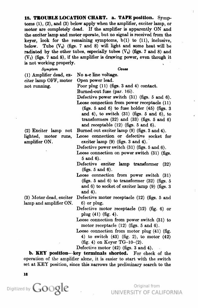
18. TROUBLE LOCATION CHART, a. TAPE position. Symp-
toms (1), (2), and (3) below apply when the amplifier, exciter lamp, or
motor are completely dead. If the amplifier is apparently ON and
the exciter lamp and motor operate, but no signal is received from the
keyer, look for the remaining symptoms, b(1) to (11), inclusive,
below. Tube (V8) (figs. 7 and 8) will light and some heat will be
radiated by the other tubes, especially tubes (V6) (figs. 7 and 8) and
(V7) (figs. 7 and 8), if the amplifier is drawing power, even though it
is not working properly.
Symptom Cause
(1) Amplifier dead, ex- No a-c line voltage,
citer lamp OFF, motor Open power lead,
not running. Poor plug (11) (figs. 3 and 4) contact.
Burned-out fuse (par. 16i).
Defective power switch (31) (figs. 5 and 6).
Loose connection from power receptacle (11)
(figs. 5 and 6) to fuse holder (45) (figs. 3
and 4), to switch (31) (figs. 5 and 6), to
transformers (32) and (33) (figs. 5 and 6)
and receptable (12) (figs. 5 and 6).
Burned out exciter lamp (9) (figs. 3 and 4).
Loose connection or defective socket for
exciter lamp (9) (figs. 3 and 4).
Defective power switch (31) (figs. 5 and 6).
Loose connection on power switch (31) (figs.
5 and 6).
Defective exciter lamp transformer (32)
(figs. 5 and 6).
Loose connection from power switch (31)
(figs. 5 and 6) to transformer (32) (figs. 5
and 6) to socket of exciter lamp (9) (figs. 3
and 4).
Defective motor receptacle (12) (figs. 5 and
6) or plug.
Defective motor receptacle (12) (fig. 6) or
plug (41) (fig. 4).
Loose connection from power switch (31) to
motor receptacle (12) (figs. 5 and 6).
Loose connection from motor plug (41) (fig.
4) to switch (43) (fig. 2), to motor (42)
(fig. 4) on Keyer TG-10-(2).
Defective motor (42) (figs. 3 and 4).
b. KEY position—key terminals shorted. For check of the
operation of the amplifier alone, it is easier to start with the switch
set at KEY position, since this narrows the preliminary search to the
(2) Exciter lamp not
lighted, motor runs,
amplifier ON.
(3) Motor dead, exciter
lamp and amplifier ON.
18
Genera
ted o
n 2
01
4-0
8-0
5 0
7:3
5 G
MT /
htt
p:/
/hd
l.hand
le.n
et/
20
27
/uc1
.b3
24
38
52
Public
Dom
ain
, G
oog
le-d
igit
ized
/
htt
p:/
/ww
w.h
ath
itru
st.o
rg/a
ccess
_use
#pd-g
oogle

oscillator and power amplifier. These components are common to
both KEY and TAPE operation. Test all tubes on a standard tube
checker before starting on a circuit analysis.
Symptom
(1) No filament volt-
age.
(2) No plate or screen
voltage on tubes (V6)
and (V7) (figs. 7 and
8).
(3) High plate and
screen voltage tubes
(Va) and (V7) (figs. 7
and 8).
(4) Low plate and
screen voltage tubes
(V.) and (V7) (figs. 7
and 8).
(5) Low or no plate
voltage tube (V5) (figs.
7 and 8).
Cause
Defective power transformer (33) (figs. 5
and 6).
Loose connection from power transformer
(33) (figs. 5 and 6) to tube sockets.
Burned-out rectifier tube.
Open resistor (29) (figs. 5 and 6).
Open filter choke (6) (figs. 3 and 4) (no
screen voltage). *
Shorted filter capacitor (4-3) (figs. 7 and 8)
or (4-4) (figs. 7 and 8).
Loose connection or open lead from rectifier
tube (V8) (figs. 7 and 8) to resistor (29)
(figs. 5 and 6) to output transformer (34)
(figs. 3 and 4), to plates of tubes (V6) and
(V7) (figs. 7 and 8); or from resistor (29)
(figs. 5 and 6) to filter choke (6) (figs. 3
and 4), to resistor (36) (on Keyer TG-
10-J), to screens of tubes (V6) and (V7)
(figs. 7 and 8).
Open primary of output transformer (34)
(figs. 3 and 4).
Open resistor (24) (fig. 11).
Open lead or loose connection from resistor
(24) (fig. 11) to tube socket.
Shorted resistor (24) (fig. 11).
Shorted capacitor (4-2) (figs. 7 and 8).
Shorted grid resistor (15-2) or (15-3) (fig.
11).
Shorted coupling capacitor (32) or (3—3)
(fig. 11).
Open lead or loose connection from resistor
(15-2), (15-3), or (23)' (fig. 11) to tube
socket or ground.
Defective or open resistor (22-1) or'(22-2)
(fig. 11).
Defective or open resistor (23) (fig. 11).
Defective resistor (21) (fig. 11).
Loose connection or open lead from resistor
(20) (figs. 5 and 6), (22-1), or (22-2) (fig.
11) to tube socket.
19
Genera
ted o
n 2
01
4-0
8-0
5 0
7:3
5 G
MT /
htt
p:/
/hd
l.hand
le.n
et/
20
27
/uc1
.b3
24
38
52
Public
Dom
ain
, G
oog
le-d
igit
ized
/
htt
p:/
/ww
w.h
ath
itru
st.o
rg/a
ccess
_use
#pd-g
oogle
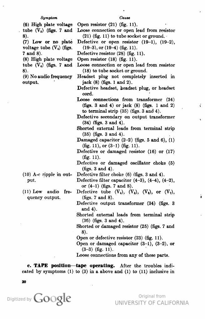
Symptom
(6) High plate voltage
tube (V5) (figs. 7 and
8).
(7) Low or no plate
voltage tube (V4) (figs.
7 and 8).
(8) High plate voltage
tube (V4) (figs. 7 and
8).
(9) No audio frequency
output.
(10) A-c ripple in out-
put.
(11) Low audio fre-
quency output.
Cause
Open resistor (21) (fig. 11).
Loose connection or open lead from resistor
(21) (fig. 11) to tube socket or ground.
Defective or open resistor (19-1), (19-2),
(19-3), or (19-4) (fig. 11).
Defective resistor (28) (fig. 11).
Open resistor (18) (fig. 11).
Loose connection or open lead from resistor
(18) to tube socket or ground.
Headset plug not completely inserted in
jack (8) (figs. 1 and 2).
Defective headset, headset plug, or headset
cord.
Loose connections from transformer (34)
(figs. 3 and 4) or jack (8) (figs. 1 and 2)
to terminal strip (35) (figs. 3 and 4).
Defective secondary on output transformer
(34) (figs. 3 and 4).
Shorted external leads from terminal strip
(35) (figs. 3 and 4).
Damaged capacitor (2-2) (figs. 5 and 6), (1)
(fig. 11), or (3-1) (fig. 11).
Defective or damaged resistor (16) or (17)
(fig. 11).
Defective or damaged oscillator choke (5)
(figs. 3 and 4).
Defective filter choke (6) (figs. 3 and 4).
Defective filter capacitor (4-3), (4-4), (4-2),
or (4-1) (figs. 7 and 8).
Defective tube (V4), (V5), (V8), or (V7),
(figs. 7 and 8).
Defective output transformer (34) (figs. 3
and 4).
Shorted external leads from terminal strip
(35) (figs. 3 and 4).
Shorted or damaged resistor (25) (figs. 7 and
8).
Open or defective resistor (23) (fig. 11).
Open or damaged capacitor (3-1), (3-2), or
(3-3) (fig. 11).
Loose connections from any of these parts.
t>. TAPE position—tape operating. After the troubles indi-
cated by symptoms (1) to (3) in a above and (1) to (11) inclusive in
Genera
ted o
n 2
01
4-0
8-0
5 0
7:3
5 G
MT /
htt
p:/
/hd
l.hand
le.n
et/
20
27
/uc1
.b3
24
38
52
Public
Dom
ain
, G
oog
le-d
igit
ized
/
htt
p:/
/ww
w.h
ath
itru
st.o
rg/a
ccess
_use
#pd-g
oogle

b above have been corrected, check operation at TAPE as follows:
satisfactory operation at KEY and no operation at TAPE limits the
trouble to tubes (V,), (V2), and (V3) (figs. 7 and 8), and their asso-
ciated mechanical and electrical parts. Make these tests only after
it has been definitely assured that the phototube aperture, lens and
mirror, controls, etc., are set according to the operation instructions in
paragraph 9. The point-to-point resistance check should indicate all
probable defects.
Symptom Cause
(1) No plate voltage Shorted capacitor (4-1) (figs. 7 and 8).
tubes (V2 and V3) Open resistor (27--1) ((27-2) (fig. 11) on
(figs. 7 and 8). Keyer TG-lO-(1)), (27) ((39) (fig. 11) on
Keyer TG-10-(2)), ((26) (figs. 7 and 8), or
(40) (fig. 8) (not on Keyer TG-lO-(1)).
Loose connection to tube socket.
(2) No keying with Open resistor (13-1) or (13-2) (figs. 7 and
tape. 8).
Resistor (13-1) or (13-2) shorted to shield
ground (figs. 7 and 8).
Loose connection to tube socket.
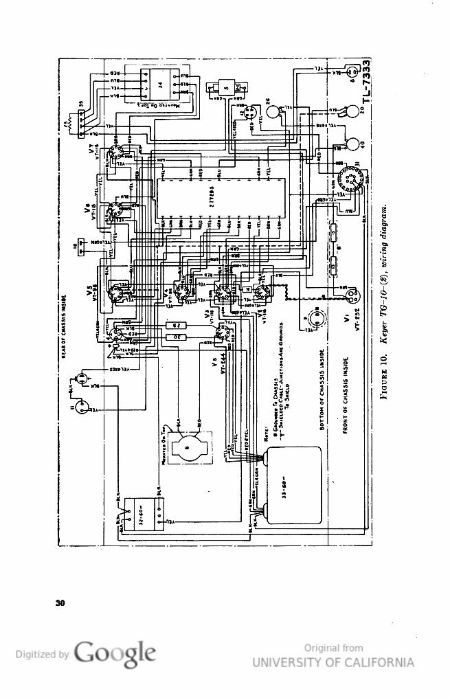
19. POINT-TO-POINT D-C VOLTAGES. The tube socket pins
from which the measurements shown in the following table are made
are identified by numbers appearing on the bottom of the sockets.
The readings are taken with line voltage of 115 volts; both bias con-
trols at extreme right; volume control advanced one-half of its total
rotation; main switch turned alternately from KEY to TAPE, as
noted; photocell adjustable cover in normal operating position with-
out paper tape or other subtsance interrupting light beam; and with
nothing connected to OUTPUT terminals or KEY terminals. The
location of the tubes from the bottom of the chassis is shown in figures
9 and 10 where they are identified by the type and tube number.
The following readings should be checked with a 20,000-ohm-per-volt
meter only.
570810°—44——4
21
Genera
ted o
n 2
01
4-0
8-0
5 0
7:3
5 G
MT /
htt
p:/
/hd
l.hand
le.n
et/
20
27
/uc1
.b3
24
38
52
Public
Dom
ain
, G
oog
le-d
igit
ized
/
htt
p:/
/ww
w.h
ath
itru
st.o
rg/a
ccess
_use
#pd-g
oogle

o
o
$
X
x ;x: X'
X
X
1 X
H
Xi
s.
i
1
9Q
1
X
Xi X X
* X
X
X
X
?*
1O o co ic
m
>O
1C
iO
OS i-H CO CO
M"
^
1C
t-
g
t>
^
6.
a
CN
OQ
1O 1O 1C 1O
•*
•*
^
•*
a
E
CO CO CO CO
V
ct
CO C-T
at
at
at
oL
|3
I-H C^ O t"~ O C1-!
O CN CC
M CO
«
CO CC
«
(N
CO
CN
1
>
cq N co CO cq cc
i-H ^-<
1
Q O Q Q
s
to 1O 1O >o oo ob
30 00 QC
at
1 1
00 OC
at
at
at
00
2
0 0 IN IN CM CN
^ CN CM
CM
IN CM
«
CN
CM
CN C
ec
I
1
iO *O CO CO CO CC
J= CO CC
id
CO CC
CC
CO
e
CO 1C
:~
E
I
T 7 *r Ir Ir Ir
SSS
£3
3
3
CN CN CN CN CN CN
rt
Cs
CN IN
"o
^
CD O O CN 00 t^
CO 00 CO
O 1O 1C
X t- •*
P
s?s
0
CN
C
CN C
1
iH
»-
cr
CO
CO t-
PL,
|
Q
3
PH
c
#
^
P
c
3
O
iO iO iO iO CO W
00 00 00 00 00 00
-O CO CO
2
CO CC
I
K
CO o
H
4
iooot
obat
at
at
oo —
c;
CM
f^ rn f^t e£>
'T
1C
1C
>o ^t
ip
-C CO CC
¥
CO CC
^
I— 1 tj-
^
C
.— 1 ^H ^H TH Oi C35
a
Ol CT
p™
T-
^
i— I O
| | | | | |
1 1 1
I |
|
I
1 1
s
E-
E-
H H H H H H
H EH E-
EH
H E-
^4
H
E-
H H
3
>
>
» » »
» >
**
> >
Iff
^
>
>• >
c
,
55
g
.
J
> > > ^>>
\ s~
•. X*
- -7
- .E
>
>
> > >
>
> >
^
>
»
Genera
ted o
n 2
01
4-0
8-0
5 0
7:3
5 G
MT /
htt
p:/
/hd
l.hand
le.n
et/
20
27
/uc1
.b3
24
38
52
Public
Dom
ain
, G
oog
le-d
igit
ized
/
htt
p:/
/ww
w.h
ath
itru
st.o
rg/a
ccess
_use
#pd-g
oogle

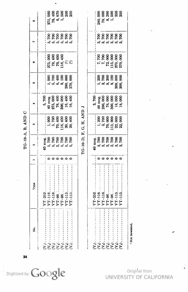
20. POINT-TO-POINT RESISTANCES, a. Resistance in ohms
from socket contacts to chassis. The tube socket pins from which
the measurements shown in the following tables are made are iden-
tified by numbers appearing on the bottom of the sockets. The con-
ditions for taking these measurements are that: the plug be discon-
nected from the power source, both bias controls at extreme left, the
volume control be rotated to extreme right; and the main switch at
TAPE. The location of the tubes from the bottom of the chassis is
shown in figures 9 and 10 where they are identified by type and tube
number.
23
Genera
ted o
n 2
01
4-0
8-0
5 0
7:3
6 G
MT /
htt
p:/
/hd
l.hand
le.n
et/
20
27
/uc1
.b3
24
38
52
Public
Dom
ain
, G
oog
le-d
igit
ized
/
htt
p:/
/ww
w.h
ath
itru
st.o
rg/a
ccess
_use
#pd-g
oogle
o o o o o o
o o t- o m >o
O H* 00 iO CM CM
O O O O "5 "5
O O CM "O IN C-5
oo
ic" 00" «5" i-T
t- t^
tN
O" OC" 00" i-T
S1^
§OOOOO
O 0 O O 0
t- t- r- r- t- t^
§§§§§§
t^ t^- t^ t^ t- t-
1C tO >C iO 1O 1C
CO CO CO C O CO CO
o o o o
o ^ ^ ^*
o o o o o o
°.°.§§§§
1O" oo o~ CO e^ c-
t- t- IN "5 O O
t- 1-1 !~• t^
t^ ^- t* T— 1
CM rf
— t CM IN
000000
o o o o o o
O t^ TtI 1-H O O
CM 1^ C^ ^H O O
tB
i-T m" co" 02" o" o"
00 1>
CM CM
i-T co" oo" of o" o"
§8
Q
g
Kr O O O O O
1
Jllsil
ul O O O O O
!§§§§§
1C
iO 00 O O CO
Cf
o GO" o od" od"
0 t- t- 0 ^ -H
•* C M >o
1-5
ig^g^^
0
Q
z
p
£
§OOOOO
O O O O O
<
•*?
o t- -^ ^ -^ -^
w
CM t- O O O O
m
<{
i— 1 1C O CO O O
t^ ^H C M CM
o"
^H CO O 1C CM IN
1> i-H CM CM
T— 1
h"
i
•> O O O O O O
"O O O O O O
o"
r O O O O O O
bl
b
3
0 o o o o o o
1
A
c
o
f
iO <O lO lO iO iO
co" co" 05" co" co co"
H
5
0
H
c
•^
~
o o o o o o
o o o o o o
'
CO CO iO >O
C^
CO ® 1O 1O
o.
tf
c^
ir
c«
1
i— i i— t CO cO i— t i— i
l-M i-H CO CO *-^ -H
i— 1 I— 1 OS Oi i— 1 i— t
^< ^H O5 O> •-< i-H
^^^^^^
1 1 1 1 1 1
H H H H E-i H
>>>>>>
1
r-
>>>>>>
h
>
- M EO •* "S « t*
- cM ':-. -r 'ir; v^~ ' t-
>>>>>>
>
>>>>>>
>
24
Genera
ted o
n 2
01
4-0
8-0
5 0
7:3
6 G
MT /
htt
p:/
/hd
l.hand
le.n
et/
20
27
/uc1
.b3
24
38
52
Public
Dom
ain
, G
oog
le-d
igit
ized
/
htt
p:/
/ww
w.h
ath
itru
st.o
rg/a
ccess
_use
#pd-g
oogle

b. Resistance from resistor and capacitor mounting card
terminals to chassis. The terminals of the resistor and capacitor
mounting card (38), from which measurements of resistance to chassis
are made, are identified by color coding (figs. 9 and 10)." Resistance
measurements from these terminals to chassis are indicated below in
the order in which the terminals appear when the bottom of the keyer
is viewed with the front toward the observer (except on Keyer TG-
10-(1). The conditions for taking these measurements are that the
plug be disconnected from the power source, both bias controls be at
extreme left, the volume control be rotated to extreme right, and the
main switch at TAPE.
Wire color code
Resistance to
chassis (ohms)
Wire color code
Resistance to
chassis (ohms)
Black
0
Yellow
250
Green
300, 000
110, 000
Brown _
9, 100
0
Blue
115, 000
Green
300 000
Red
115, 000
Red
18, 000
Yellow
1, 500
0
Green _ _
8, 200
Blue
550, 000
Blue
70, 000
45, 000
Brown
72, 000
18, 000
Red
78, 000
480, 000
Yellow
8, 200
Green
7, 800
Brown -_ _ . _ ,
3, 700
Yellow
1, 250
Green _
280, 000
3, 700
31. INSTRUCTIONS FOR FUNGIPROOFING AND MOIS-
TUREPROOFING. The instructions contained herein are a guide
for processing Keyer TG-10-(&).
a. Unscrew and remove the six screws and washers holding the
front panel to the case.
b. Turn the unit over on its side and remove the three screws,
nuts, and washers holding the chassis to the bottom of the case.
c. Turn the unit to original position and slide the chassis out of the
case.
d. With a clean cloth; remove all dirt, dust, and rust or corrosion,
from the case and chassis.
e. Remove the following tubes from chassis:
2 Tubes VT-116 1 Photocell (RCA 923).
2 Tubes VT-96 1 Tube 5U4G.
2 Tubes VT-115 1 Exciter lamp (Mazda No. 1000).
Genera
ted o
n 2
01
4-0
8-0
5 0
7:3
6 G
MT /
htt
p:/
/hd
l.hand
le.n
et/
20
27
/uc1
.b3
24
38
52
Public
Dom
ain
, G
oog
le-d
igit
ized
/
htt
p:/
/ww
w.h
ath
itru
st.o
rg/a
ccess
_use
#pd-g
oogle

f. With masking tape, cover—
(1) Nine tube sockets (top).
(2) Lens of exciter lamp, rear and front of panel.
(3) Around base of motor plug and socket.
(4) All vent holes around top, sides, and bottom of motor.
(5) Oilholes and shafts in all gears and bearings.
(6) Neoprene ring for drive roller.
(7) Battery connector lugs (at rear).
•g. Turn the chassis on its side and remove the four screws holding
the panel base to the chassis. Remove the panel.
h. Untie the lacing from the cable form and allow the wires to
hang loose.
i. With masking tape, cover the jack contact and jack collar.
j. Loosen the knurled nut at the base of the photocell tube cover
and remove cover. Mask the socket with tape.
k. The unit is now ready for baking. Place the components in a
heating apparatus and bake at a temperature of 160° F. Do not
exceed this temperature. Bake the unit for approximately 3 hours.
Watch for indications of melted wax; if this becomes evident, lower
the baking temperature, adding 1 hour to the baking time for each
10° F. drop.
1. After baking, remove the components of the unit from heating
apparatus and apply varnish to all parts and exposed metal with a
paint brush or spray. Follow the instructions provided with the kit.
m. After the varnish has been applied, replace the unit in the
heating apparatus and allow it to remain there for approximately
30 minutes until the varnish has dried.
n. Remove the unit from the heating apparatus and repeat the
application of varnish. Replace it in the heating apparatus. Shut
off heat and allow unit to cool for approximately 12 hours. When
the unit has returned to normal temperature and varnish is absolutely
dry (not tacky), remove all masking tape.
o. Clean off any excess varnish on those portions where it will
impede electrical continuity or mechanical action. Extreme caution
should be taken when varnishing around moving parts, as varnish,
when dry, will impede the mechanical motion.
p. Upon completion of baking, remove the unit and spray three
or four coats of varnish on exposed elements and surfaces. Do not
spray front panel of unit. Spray the inside of the case. When var-
nish has dried, remove masking tape.
q. Replace all parts removed; oil all shafts, gears, and bearings.
Check the unit when assembled and mark it MFP (date),
to show it has been fungiproofed and moistureproofed.
26
Genera
ted o
n 2
01
4-0
8-0
5 0
7:3
6 G
MT /
htt
p:/
/hd
l.hand
le.n
et/
20
27
/uc1
.b3
24
38
52
Public
Dom
ain
, G
oog
le-d
igit
ized
/
htt
p:/
/ww
w.h
ath
itru
st.o
rg/a
ccess
_use
#pd-g
oogle

£
a
•8
I
I
H
X
o
27
Genera
ted o
n 2
01
4-0
8-0
5 0
7:3
6 G
MT /
htt
p:/
/hd
l.hand
le.n
et/
20
27
/uc1
.b3
24
38
52
Public
Dom
ain
, G
oog
le-d
igit
ized
/
htt
p:/
/ww
w.h
ath
itru
st.o
rg/a
ccess
_use
#pd-g
oogle

28
Genera
ted o
n 2
01
4-0
8-0
5 0
7:3
6 G
MT /
htt
p:/
/hd
l.hand
le.n
et/
20
27
/uc1
.b3
24
38
52
Public
Dom
ain
, G
oog
le-d
igit
ized
/
htt
p:/
/ww
w.h
ath
itru
st.o
rg/a
ccess
_use
#pd-g
oogle

29
Genera
ted o
n 2
01
4-0
8-0
5 0
7:3
6 G
MT /
htt
p:/
/hd
l.hand
le.n
et/
20
27
/uc1
.b3
24
38
52
Public
Dom
ain
, G
oog
le-d
igit
ized
/
htt
p:/
/ww
w.h
ath
itru
st.o
rg/a
ccess
_use
#pd-g
oogle
•e
e
M
H
s
Sr
t
30
Genera
ted o
n 2
01
4-0
8-0
5 0
7:3
6 G
MT /
htt
p:/
/hd
l.hand
le.n
et/
20
27
/uc1
.b3
24
38
52
Public
Dom
ain
, G
oog
le-d
igit
ized
/
htt
p:/
/ww
w.h
ath
itru
st.o
rg/a
ccess
_use
#pd-g
oogle

—38
T 1-
* ON TG-|0-A,B,&C
TL-7334
FIOUKE 11. Schematic diagram of resistor and capacitor mounting card.
81
Genera
ted o
n 2
01
4-0
8-0
5 0
7:3
6 G
MT /
htt
p:/
/hd
l.hand
le.n
et/
20
27
/uc1
.b3
24
38
52
Public
Dom
ain
, G
oog
le-d
igit
ized
/
htt
p:/
/ww
w.h
ath
itru
st.o
rg/a
ccess
_use
#pd-g
oogle

€«
i^ O
1
§
8-
o
§
"
CO
CO
CO
CO
•S"
«i
Ss
FJ
|e
CN
v^
V*
v«
cs
3 i
§1
II
1
as aS
1
6?
DO
D
r3 V
C ft
0.
_o
I
•1
60 C
O
s cu
cc
00
i
1
I
3
3
OJ
O
o
TS
•o
M
1
1
1'
a
•c
•S
B
1
1
]U
hi
o
3
B
_o
o
ft
-4i
1
•3 60
"S SP
"3
i
'3
s^
5 3
v
ft
n
1-
OQ
rv
s
o
O
^S
0
*r h
« c
„ .,
+r fc.-
ng
C 03
~ 53
c h
C o5
» 3
S 5
0) -g
.,.
o. S
0 3
0
Is
g
si
ft
:l
o
2 |
•1
-t^~
-w ft
«Jf
1 ^
o
1
^od
ffl 3
S 3
CD fe
» 3
0
2 •*
o
s ^
o
P
41*
o P
S u
ij O ^
^ 60
41 -1
-1--I
+*
1 "* O
H
>
>
ti
S^||
Ti C
M
^ CM
o M
^^ 5 cc =tt
!»
d
e
O
d
•d
M
i
CU
e
b
h
ft
m
0
o
0
03
!
•g
•P
*•»
I
I
!
*o
pa
!
i
s
O
O
a
a
1
&6
O5
l
ll
i
'J<
I
I
w
a
^4
^
l— C
T-H
S
tO
6
6
O
0>
Q
o
Q
Q
Q
w
CO
CO
w
C
O
CO
a
pa
8
a .
gj
£0
,~.
t~\ ^
A
Q .
^
fZ
0 «
^ 0 W
CM° W
Q
ft W- O W
S*
PH
PQ O
V ffl
i ^ PQ O
1-H ^H fe
N "- ffl
w "^ PH
CO ^t
•^H CO "- PH
Genera
ted o
n 2
01
4-0
8-0
5 0
7:3
6 G
MT /
htt
p:/
/hd
l.hand
le.n
et/
20
27
/uc1
.b3
24
38
52
Public
Dom
ain
, G
oog
le-d
igit
ized
/
htt
p:/
/ww
w.h
ath
itru
st.o
rg/a
ccess
_use
#pd-g
oogle

S
CO
CS
CO
t^
CN
1O
CO
CO
co
CO
r-
<
E
tr
p.
St
PC
r
S
s
1-
5
o
w
1
ft
>•
6
.
f.
t
'5,
5
c
1
|
C
•C
c
c
c
^ O
I
be
Q
1
1
0
O"
7
1
0
o
18
O
c
£
V
I
O
E
3
*
w
Dur-section aluminum can, 10"0-
1
£
ank, 450-mh. air core, #T-46005___
CO
P W) J.
*-H rt^
contact, fiber-mounted, screw type,
#2-50.
ft
4*
o3
CO
2
S o S
°ll
d o^
« 0
•c
OJ
OC
o
«
G
•slg
ISJ L,
7
u
•g
c: o3
^2
h
"S
o
3-1
1*1
r\
W
•3
c
o
A
«
0
electrolyti- #FPQ-434.
-C
1
lj
ef S J
is
o
ft
T
S
is
3
|P
•-H =t^ S
•o
§
'S
Q
^
0
S-gs
6
"?
a
bo
-*i tH
a
+
Si"!
i, a Ck d
M"
o ^?x fd
S OJ o 'W
•u
^a*
of
i
N n TJ
1"^J
| ~ ^ ^
«
6
G
CD
O
h
OJ
ft
s
O '3 3
T—I
d
111
6
a*
*^ Ol O I3
ct
o cj o
— ^ *> .Q
fe
H
s
ci
ei
d
^
;
CD
•a
U
ft
G
ft
3
s
1
a
a
'8
O
a:
3
1
tn
H
K
„
o»
04
1
CO
OJ
§
erf
i-4
iH
0
0
CO
CO
pQ
C
1
iH
I
1O
I
CO
SI
SI
CO
CO
CO
CO
CM
CO
O*
CO
g
I
s
%
£
-.0 W
7 PQ O
* <! ffl
Q >-»
o M
PQ O
O ^
O W
pQ O
co <! fe
-
O
Q --
O W
PQ O
Q -»
O W
PQ O
P ^
O W
—3 ° ~
8S
pQ O
•- fe
33
Genera
ted o
n 2
01
4-0
8-0
5 0
7:3
6 G
MT /
htt
p:/
/hd
l.hand
le.n
et/
20
27
/uc1
.b3
24
38
52
Public
Dom
ain
, G
oog
le-d
igit
ized
/
htt
p:/
/ww
w.h
ath
itru
st.o
rg/a
ccess
_use
#pd-g
oogle

I
a
S
a
o
Q
2
».
m
IN t^ C
00 «
T— 1
CM
M
A
w%
co -H ir
1C >C
CO
CO CO
CO
CO
CO
If
CM CM tN
CX tN
CN
CM
94
«
3 £
1
i
d d
o'
d
s
^ ^
PH
PH
g
ffl
2
CO
1
j
•
1
oi
II
•o
•o
0
§
^) "§ C
O)
f
1 "I
C —
'E
1
_£
$
£, ft ^
!3
i. i:
S 5 £
III
* § bC
o
"E.
b
1 §
Oscillate
Cathode
sv 4
1" S
4
h
O
1
§S *
£ $
I
1
f
|
8. =5 •*
\ 'S ^
* - t
fc
K M
•t
m.
S
I - 1
1
I
a
£
1 M \
S
O
V
1
11 *
i, g 0.
S
&
S
a.
I
fi"
s
^ | c
^ a7 -H -f
2 o
to
o .
o
S §
-H^f
3?
-H -jx
s,
i
5 S •+
Q
c /
H ° f£ H
H
H
H
e
8 | GD 3
- « ^ p; p- pq
70,000-ohm,
carbon, #B
8,000-ohm,
carbon, #B
90,000-ohm,
carbon, #B
i— i
-»
j-jsa 1
=«^ -H =»^ S =*
- 0 =«= „ c
c" r-e ?c"
0) -a) a
1 II i!
-3 -rt b -3 S
S « c 2 £
8 ,;« g«
S .2 » 2 H:
ip (P c
o
i>
0
|z< fe IN
Th IN
CM
CO
CO
%
OS
K
1 1 1
i
t-i t-
1
1
O O
•** **
CO CO
g
In
§ "i I
'« 'tp
i
'§
's
mil Corps
tock No.
CO £ (S
K rt
S
ffl
«
i
4 •*' e
•41 t^
od
op
00 00 tN
OS CN
CM
CO
en
OS t^
CO
CO
CO
CO
§
SI SI S
S] !SJ
SI
SI
SI
SI
I
IN CM f
CO CO
CO
CO
CO
^z
H,
B ^
QH, QH, Q h
•5 * Q *,
Q
^ OH,
P H,
V
O O -
"OW O B ~ O f
3 CM"O B
O
B OW
OB
W
pq ffl
PQO_«P3O i,P5c
5 1 pq O
P5
O ^ ffl O
ffl O
i-i •< 1-1 Q i-
<!(iHrt-<!lHi-I'<f.
H ,-H <! PH
1-1 <J
pL< rt <1 ft|
<3 fa
i-H
S4
Genera
ted o
n 2
01
4-0
8-0
5 0
7:3
6 G
MT /
htt
p:/
/hd
l.hand
le.n
et/
20
27
/uc1
.b3
24
38
52
Public
Dom
ain
, G
oog
le-d
igit
ized
/
htt
p:/
/ww
w.h
ath
itru
st.o
rg/a
ccess
_use
#pd-g
oogle

S
n
e
CO
"5
CN
O
I*.
CO
CO
CO
CO
"5
co
CO
CO
CO
CO
CO
CO
CO
t-.
r-
**
CN
K
CM
c*
CM
N
CM
IN
CM
CN
d
d
d
d
d
d
d
d
d
ffl
P5
PH
PH
P.
PS
PH
~
I—
*
1-1
^
CO
CO
1-1
Ht
1-1
-.
"S
rft
o
T3
v
-3
CN
3
g
«
T3~
8
00
0Q
cu
IH
%
n
03
03
scillator pla
resistors.
S
o
o
m
late load, Is
I
z
1
hototube bi
hototube bi
•3
3
•3
1
•S.2
||
ffl 0
||
CD •
o
"3
-o .2
I
11
S *
45
O
>
6
PH
HH*
O
o
PH
PH
•""
>
S
•d
o
3 o
1
§
1
1-t
O
| *
wire-
g
'i
IN
a2
Is"
^
+k
ft
ft
C O CM
o
">
^
- ca
ik
7,000-ohm, ± 10 percent,
carbon #BT-H.
00,000-ohm, taper C wire--
'O :*t
,500-ohm, ± 10 percent, 1-w,
wound, #BW-1.
00,000-ohm, ± 10 percent 1-
bon, #BT-1.
50-ohm, ±5 percent, 10-w, ^
wound, #10-K.
00-ohm, ±5 percent, 10-w
wound, #10-K.
'olume control, 500,000-ohm
,000-ohm, 2-w, lineal taper
wound, with moisture se
special shaft, \}i" diameter,
,700-ohm, 2-w, #BT^2
,500-ohm. ±10 percent, 1-w
wound. #BT-1.
§ S"
1 %
K C
el
o
-H
i;
.6
g"
5 "3 N
S|
CM
"5
'S-S*
*-<
i— i
csT
CN
^
i^-
i—1
CN
u
m
t*
L
|
J
~
!
1
QJ
'
^»
PH
-W
|
9
1
|
a
|
1
o
1
loo
1
!
S
_o
1
1
•1
a
^
Q
-2
*OQ
|
'58
'S S
1
"^,
-2
5
7
1
pi
«
«
pi
£
O
£
«
I
i
CN
Q
O
„.
0
„.
g
g
o
1
co
CM
u5
—!
i
i
ll
$
i
§
T— t
OJ
S
i
CO
CD
CVI
CO
CN
^H
CM
50
IN
,_l
^
o
IN
CO
CO
CD
SI
CO
SI
SI
N
X]
Si
SI
S3
S)
SI
N
CO
CO
CO
CN
CO
CO
CO
CO
CO
CM
CO*
58
"•5
w
3
O ^
0 W
Q2
Q H,
o >->
Q
^ Q
W 0
»
O
O
0 iH
-H O W
0 K
O
W 0
O
J PQ
35 O
rt 33 O
I4j i-^ o
„. ffl O
PQ
O n ^
O pQ
ffl
PQ
. ffl
i— i ^J
ffl IN
<! fe
N ^ PH
IN < 6H
cq <! P^
CM <
fiI IN <!
ffl c<i <!
IN Q
CM <!
CM Q
35
Genera
ted o
n 2
01
4-0
8-0
5 0
7:3
6 G
MT /
htt
p:/
/hd
l.hand
le.n
et/
20
27
/uc1
.b3
24
38
52
Public
Dom
ain
, G
oog
le-d
igit
ized
/
htt
p:/
/ww
w.h
ath
itru
st.o
rg/a
ccess
_use
#pd-g
oogle

I
r
c
o
Q
m
H
P§
2
p«
S3
•0
CO
~r
M.
O Cv
co
01
r*
w
fe C
CO
CO
CO
co p-
en
O1
co
w .
CO
CO t>
^H
tN
^_
W
|.|
£
CN CN
r-
t~.
||
IN
IN
i
t
1
CM
CM
ea
IN
I
1
1
1
•
1
e
1
S
PH
OQ
ft
OS
ft
a
S S
a
tc
ffl
H
H
H
1 (.
(
0 H=
0}
a
"S <•
*C
cC
•
S
ffl
v
0 l
""
iS
m
|
g
.2
3
%'
>
.£
,j5
-c "c
s
03
p
•3
-9
•o
« K
p
^
£
o
o
o
+-• fc.
^J
tc
t*
M
js
S V
a
cS
os
CD C
o "*-'
C D C
a
3
2
*•*
is'?
'.Q
S 'S
C Jt
i
O
0
0 C
•" 3
c
o
^
H
H
ft.
=-
J
i
J>
£
i
£
ff
•S £
14 1
1
'S
P
|
i C
^
Igl
fr.
Jf"
is
6
&T
i ^
-M
&S £
6
r t ^
S
co
c
co 03
. - ^J
Q, (S
"CO
£,
g CD ^-
6 r
t
1 c
^_ =t^
§TS
>r! •-
v, 47 ma; sec. 6.3-v, 6
tropical treatment, #T
110-v. 25-ovnlfi. #T-460C
v, 150-ma; 5-v, 4-am
amp; tropical treatme
cial leads, #1-46002.
Description
1
£
4,000-ohm, ±5 percent,
wound, #10-K.
CO «•
C O 03 I£)
"3
I
25-cycle).
Power. 110-v. 60-cvcle:
*-j"
C
§?
O
-H C.
CO C
a .
^
a" 1
3 •S H
S ffl *
CO
•o M
""J
1 i
& 0 ^"
>•"
^ i £
-H*
ft cc
T£H 03 o
-^> "^ 1
!«'
o §
CO +;
. -g "O ^
*„ N
o o
o"
jf E
boiS >"
6 &
o •-
•s-2
?•'?
§
tN
^ CC
i-H
I
1
1
4D
te
i
h
I
CU
X
£
g
G
I
8
1
|
<g
o
1
1
I 1
§
1
oc
a
i
'1
S
a
c
d
I
(S
o '^
a
a
c
1
PS CC
H
J
£
H
§=>
!
!
o^.
IN
O!
CO
. i*a
i
ll
f-.
S
CM
15
tl
o
CO
CO
CM
IN e<
i
i^
5
oo oc
OS
CD
01 o-
05
SI
SI N
SI
SI
S
S
8
CO
CO
CO
CO K
N
IN
IN
H .
I1
Q -»
o a
Q >-»
a
Q a
1-5
p a
1-5
o a
o a
O
ffi
IN <J £4
P5 O
CO < fe
w <l cc
r\ N
H co
< w
ǤS?
, CO
OO
PQ fe
<1 CO
36
Genera
ted o
n 2
01
4-0
8-0
5 0
7:3
6 G
MT /
htt
p:/
/hd
l.hand
le.n
et/
20
27
/uc1
.b3
24
38
52
Public
Dom
ain
, G
oog
le-d
igit
ized
/
htt
p:/
/ww
w.h
ath
itru
st.o
rg/a
ccess
_use
#pd-g
oogle

co
CO
oo
^<
r-
s
1O
CO
00 ?4 'O O
CO Os i—' Is**
OO iO •—i CM
d
do i-
P^
rt ffl 5
H-
h-
h- •
SO m
HH hH <.
«
c
C
C
S3 S C
- M C
.2
a o3 «
« s fc.' 4
£
•^ IC 3) g
o is •* c
g
c
9
3 0 50 *
s^t S
8
S
1
3 s I-S
, ft *s jy .»
*» £ i-
ill!
T
T
-4.
3
"£
.L
C
S
*
I
II
|S ,
\if
Vernier
*J
9
b£
f.
•a
H
£*
o
D* *{§ J5
c
t
O
V
1
H
3
"^ SQ
co S i^
o
S.
«
EH
O
0
w
°;|i
1
cT •
M)
J
II
1
2
111
o s;
•S i
'3
s -^ §
•+3
§«
6O
PQ
15 T3
C
I
1
te
c _•
a
'O
utput pri. 8,000-ohm C. T.:
4-, 8-, and 15-ohm, tropical
ment with special leads, #T-
contact, fiber-mounted, screi
#4-50.
_ _o
akelite card including solderi
and mounting studs, specia
000-ohm, ±10 percent, 2-w,
)0-ohm, 2-w, linear taper,
wound, with moisture seal a
contact, polar-ed, shielded,
ture, #MP4S.
10-v, 25-cycle, #CX-21325__
10-v, 60-cycle, #CX-21325__
15-v, 60-cycle, 0.65-amp,
pole, phonograph-recording
GI tvpe, RX with special
#23028.
"S;
5 I
4~
.S
•*
c.
1
c
- .2
c
c
S ^
l» ^-J
C'
J3 »
O ^&
oo
.S S
J
0 =I^
Q
0
•v
V>
«
V
S
?
•41
>H
rt
1-1
t
•g
J
S
g
"i
d
be
a
fe "5
h C
|U
0
O g
w *p
o 'S
C
-3
S §
1 S
io ^
; M 2 3 3
i
g 0
1
(S Pu
3 O 0 0
H E-
PH r**^
PS
E ^ ^ ^
g
» ? 7 «J
U5
IN M
« ^
K
IN IN
CM •*
iO O
et
l> OC
^000
co c
.N -
e
oo «
S? X X s
05
N
§
SI
CO
si
Si
(N
R
co
CO
n
CO
=
CO
Q >-»
O W
Q -»
O M rt
CO <1 fn CO CM
Q >-»
o a
PQ Q^
co ^ ffl co
-
o
III
>-5
w
o
<! TH
3
o
37
Genera
ted o
n 2
01
4-0
8-0
5 0
7:3
6 G
MT /
htt
p:/
/hd
l.hand
le.n
et/
20
27
/uc1
.b3
24
38
52
Public
Dom
ain
, G
oog
le-d
igit
ized
/
htt
p:/
/ww
w.h
ath
itru
st.o
rg/a
ccess
_use
#pd-g
oogle
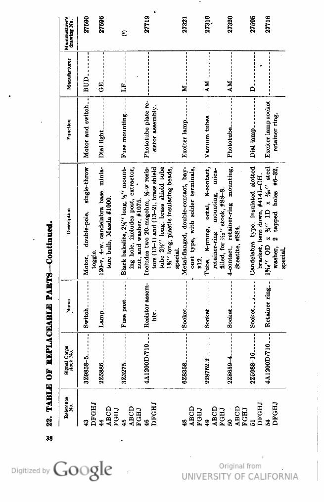
-™ .
0 cc
--I 5
OS C
1C
CO
i:l
C* O"
-H IM
?
i— t
1C* 1C
t- cc
CO «
jl
r- b-
t- b-
1|
N IN
5^ CM CM
cq c<
IN
Cfl
3
B
Q
5
OS
« C
S s
O
1
1
"8
j3
0) .
«• II
— >.
Q
.2 "S. 1 c
IA
g »
|l
J
o:
_g
I
"H ^
3 .§ S «
5 J
\
S.
2 1
• I |S i
1!
a
j
||
s
_. -ii "S ."*"
3 •£
3
*2 v
0 «
3 ^ '* 5
c C
X t-
§ C
03 ,c
Q
Pn ft. K
> P-
W
jj i
Black bakelite, 2%" long, h" mount-
ing hole, includes post, extractor,
nut, and washer, #1075.
Includes two 20-megohm, %-w resis-
tors (13-1) and (13-2), brass shield
tube 2]4" long, brass shield tube
1%" long, plastic insulating beads,
special.
Metal-fianeed. double-contact, bav-
onet type, with solder terminals,
#12.
Tube, 8-prong, octal, 8-contact,
retainer-ring mounting, mica-
filled, for "32" stock, #SS-8.
4-cont,act. retamer-rme mountmer.
Steatite, #SS4.
Candelabra tvne. insulated slotted
"» CM
1 1
1 1
§**
2^1
53 X
ture bulb, Mazda #1000.
TJH j^ O
I
Description
» 1
I 1
C Q T)
. "c
9
3 C.
_Q X M
M
C
a
a
ai 4
f _ a 1
>
s|>
3
T-t
4
1
i
|
3
S
ft3
00
•B
^
8
"S a
02
*
S
P
° 0
1.
•S =
*•* P
'S H
|
a
1
S
fe »
CO i—
3 ® C
o c
o
•g
o c
co v.
0
?
cc
i
S
!
1
a
£c
OS
03
4
Is"
i
^
I*
oo cc
1O oc
Q
u5 2 oc
I
g 5
!•
Q
1
.11
^ O ic
OC
O:
O3
00 OC
ca IN n
So oc
^
OS 1C
C O •"* OC
if
N <1 ts;
C^ tv
a
cc -^ cc
IN IN
c~
a
S
ll
c
I-S
1-s
>-5 '-S
^
5
O
Q ^ Q -» a
OB o a o
Q -j Q ^
OB OB
Q ^
0 B
B B
O O
e
M
•* Q •*
"g^^gso $
^gs
Q SO
38
Genera
ted o
n 2
01
4-0
8-0
5 0
7:3
7 G
MT /
htt
p:/
/hd
l.hand
le.n
et/
20
27
/uc1
.b3
24
38
52
Public
Dom
ain
, G
oog
le-d
igit
ized
/
htt
p:/
/ww
w.h
ath
itru
st.o
rg/a
ccess
_use
#pd-g
oogle

)
e
CN
^H C
>o
"O —
IN 03
-i"
O5
1
— *
IN
1
£•
S K
IN
CO j-
U5 1O
W5
LO
1
IN Cv
CS
IN IN
IN IN
CM
M
1
L,
i-
1
3
g .
0
)
i i
bi) b
0 bO
3
1 I
!.i
G b£
1
etainer..
stment.
a
o3
.9 .£
'53 '5
•^ .s
s 1
3 E
en
la be °
§ 1
S i
1
1
4^ T*)
X1 CO
3 _
JQ
9
,J3 ^:
on
S .S £
I?
Photot
1
02 t-
P?
fH ^
T3 o
1 8
o
O.
1" 1
S 0
•a
O
1
i
O
o
s"
T3
•?
«" n"
£
1
of
€
•g-a
13
JQ
S
be
03
2 '3
4—
«P
d
13 "S
•a S
<
3
w
ii
w
- §,
OS
03
'53
'*.
s
3 o3
^M
« .
^ 02
01 ^
0)
bO
53
•O
oT
1-1 ^"
3
d
1
* 1
d "o
3
HD
a
J*
C*
x" K
13 ,0
co f*
§
"S
DQ
CO
Q &
O «
s ^
5,
cu
d
d
s.
— 3
; 1
0)
tt
s.
a
•S
a
a.
X
en
V
C —
o3 c
-"1
1
^x
T3
SS
i
M
'3 co
W r-L
_id
"3
_d
I
includes
special.
Molded g
special.
Molded bal
1
o) •
special.
42 teeth, lef
bakelite,
i;
a
.—i
^ 5
x-f *
1
00
0)
W 8 ft
1
•8
a
o
x ^ Q
o;
° «
Q
k
&
i
i
i
i
i 2
•i
8
be b
> i
'£
.S .£
>>'
*j
ffl
M , * 0
i
t*4
1 I5
9
o9.
. S
o»
o 3 c
3 .
i
1
&
5k
t ~
ts
1: af
j t
"« "a?
0)
1
5
'o
8 % £
S o
S t
1
) -^ hj
II 1
J •£
1
jJ.2
sic
w °
s
*
• —' 03 •?
03 .~i
O £
t- h
"^
o
1
S ^
"*
CQ PQ
w
o
1
I
t
1
i
i
1
i i
j
t
SJ
t
1
1
i * i
I
i
)
o
N'
N OC
IN"
"5
"5 —
C M CO
•*'
05
i-H
C4
CN
CM
s -
s s
s
5
S
-
g
^
<l C
<<
p <
r P Q
Q
Q
o
o
o c
O
CM
§C
C, S
§ §
§
3
N CN
IN CN
1
^
<J <
<<
<! <
^ <
^
3
'•<*
^
•* -^
•*
•* Th
•* TM
•*
5
1
i
S
>-s
>-»
>-»
>-s
i
W P I~5
P *->
tn
w
W
«
K
O
O O ffl
0
0
o w
o
o o
O
• o
O
ft< PQ rK
co JS o-
co P ce
o>
<: S p S
s p
So
1 •*<
P CO <1 fH
co <3 cc
O co
<! Pn
a
'O
39
Genera
ted o
n 2
01
4-0
8-0
5 0
7:3
7 G
MT /
htt
p:/
/hd
l.hand
le.n
et/
20
27
/uc1
.b3
24
38
52
Public
Dom
ain
, G
oog
le-d
igit
ized
/
htt
p:/
/ww
w.h
ath
itru
st.o
rg/a
ccess
_use
#pd-g
oogle

M
o
Cfl
1O
e
CO t^
'-_
^
IN
[SB
^r
"r C
r~
^H
1-1
C^ CM
cc
C"
CO
CO
CO
3
i— i iO
I—
"O
H c
[p..
*•
f ^
!•„
i"— r*.
t*
t^
(-
[^_
s'i
IN
CM
e«
N O)
C-l
IN
N
!r
1
3
a
« Pi
i— i —
£
03
Q
V
ft C
S ^
£
"E
;c
»> ^
-i-i
« V
t
73
*E "^
•3
15
"&
e
.2
CD
C
D
i A
a g
J3
a
|
en
t
a
a
9C
a
s s
"
3
c
3
en
— H
—
• —;
—
ffl
C
CD
3
*~^
s
0O
-j _O 00
a
2
3
V ^
a
£
a
S
".2 >
I
i
3
<D
£ S £"S
H H
a
1
- 1
1
1
ct
a
H
O
«
6
In co"
s |
f
•s
% s
P"
(H
?,5
0) M
> 3
'-2
0
^
— -H
O
O
co be
O) '£
molded'
ameter 1
•3 «>
o
2? ^
'S *
$
g
o a
6 £.
o5
1 c
h
1'^
m
c-< Q
n
o>
a
V
73
45
O)
'T
a
.Q CO
^3
° G
d
15
"3
O o
|
O -o
1=3
11^
73
* r
ID
M
_ft
"o
_c.
l-H *
"3 ^
i
*S o
%" diameter stee
S *
be
^ c
rs— Continued.
1
P,
Tape drive roll sh
diameter steel, 5.
3 .2
00
CO
"be S
P"
ao,c
^ 1
ri"'4
_o ^
p
II
II
S j
h +"
d o -
1— t
^5,
00 M
o3 C bl
d '^
cS iT
C)
.5 bi
o a
3 bC
11
o ° -2
°! 5?;
7g|
2^3
CO
o o3
£.*>
|1
2 00
00 O —
"C ^
. +3
tN"""
CO
w £
w 'E"'
•* 15 =»=
0 »
1 >
§ S Io
«
P
P
P
=t^ fS
§
0 'a
§
73 b£
be bo
«
O)
s s
a <=
a a
04
•c -c
"s
_> en
a
"n
01 41
TO CO
EABLE
1
asseml
Cone
d c!
0
, . ft .
Rocker
support i
blv.
£ £
a a
o o
h 1 t-
IB
1
a
B
^B co S
'° a "2
1
O X!
3
o
O
EH
a
02
02
w
1
1
|
,
,
i
^
1
1
1
i
(J
^
o
*<
1O
CO
CO ^-
o
tN
^
CO
.
o-0
CM
1 — 1
IN IN
S
2
CO
1O
CO
I— 1
&
LQ
rt "5
u5
(6
3S
P
1
p
p
^ P
0 O
p
p
p
1
o
o
|
O
C
e
§
H
i S
|
E»
tN
CN
O
•**!
5
3
3
^ ^
3
3
3
3
3
«
£
-
."fl
o.
1-3
>-)
>— ,
>-)
t-S
>-s
"~
".-
|l
M
H
M
a
X
w
p -»
w
i
O
0 O
o
0 0
o
0 O
o M
o
g
W
"SP
/T] fi^
00 ^
"gP
_ CO O
Ǥ
KP
^
KP
!>• ^ t^ H
e
00 P
40
Genera
ted o
n 2
01
4-0
8-0
5 0
7:3
7 G
MT /
htt
p:/
/hd
l.hand
le.n
et/
20
27
/uc1
.b3
24
38
52
Public
Dom
ain
, G
oog
le-d
igit
ized
/
htt
p:/
/ww
w.h
ath
itru
st.o
rg/a
ccess
_use
#pd-g
oogle
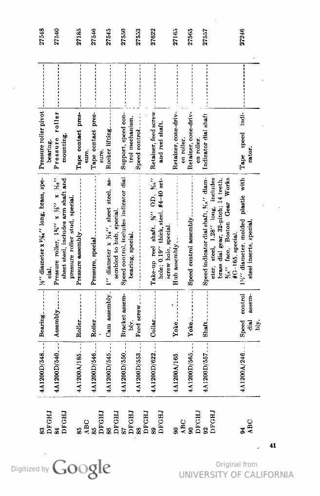
00
0
>ft
CC if"
c
ec
IN
t^
iO
, ,
CC'
"5
-p
-T 1
CC
F— i
1O 10
1O
i^
CO
iO
i?7
CN
CM
IN
J- t^
IN
IN
CM
01
0
h
V
a
s
t
c
oJ
.>
C
"3
• 1
0
t-
O<
bearing,
ressure rol
mounting.
o.
a
trol mechanis
ieed control
Si§
etainer, cone-d
T
OQ
43
^ CJ
o |
EQ
•g^
i
[3
•o
"o
§
§ I
J ^
. 5
t, C J t.
•3
1
1
*" i:
c. s
o —
- "oJ
|
&
(H OJ
1 II
= '3 «
w
|
B ° aJ a
o
a
V ti
S
H CD ^ -^
3 Q, " C,
11
&
O5
—
» 5f « j
« •*
G) fl\ V
'O
03
O
PH
PH
E*
H (£.
c5
•r.
Pi
K
«
«
EH
10
00
-o
s
S
t
I "O
2
si
;
^
i
GO 'X
A
.
X 03
03
•5
™?
^
1
.S
"2 « "1
•g
„
+a
i — T
^H
o
•3
~- ^ K*"
1
^ 03
3
CD
45
OQ
O
BS
Q
•*
1
•*
!
.e
'bBi- g
i
^ E
5
^CJ
o3
~(
2.
ao
CD
"5 S
-.
^_"
.^
= s o
H" diameter x *%t" loni
cial.
Pressure roller, 134" x
sheet steel, includes a
1" diameter x >16", sh
sembled to hub, speci
Speed control, includes:
bearing, special.
Speed control assembly.
Speed indicator dial shaf
o .-g
•o"
OD
:}§
#G-165, special.
]':>" diameter, molded
steel inserts, special.
M (,
CD S
1
I
•S
^ "3
f J>
00 M *-
CM ^ §
If
*|1
t-^l
"3 — tD~
CD 03 O
£ «
"S =3 £
g £
:
IE
K
tc £
I
QJ Qj CC
QJ 03 vec
£ I
1
c
2 S x
;
a i
£
gp
3
E
J<!
03
f*H • K ^"
B
i
as -Q «™
S £
i
i
i
S
5
IfJ >>
CC P
'
i
5 2*
CO
m
i
0
2
, f-
i
.1
60
"S t.
5
t
•
03
S • v
j_
_ — .
'C
\
a
H
O """' ^
c3
Q
v
^
^ Cj >j
c3
1
I
S
a
t2
oS
o>
0
•3
- o
03
ffl £
>
CO
CO
tO
>o
co
-T
o o
§ §
Q Q
o o
CM CM
R
o
o
<!
O
§
-
C
53
O
O
53
O
C
53
O
H
C
O
n fe
oo P
««*
oo ". oo
CO
00
«o
< a-.
C O
O
PQ
<!
41
Genera
ted o
n 2
01
4-0
8-0
5 0
7:3
7 G
MT /
htt
p:/
/hd
l.hand
le.n
et/
20
27
/uc1
.b3
24
38
52
Public
Dom
ain
, G
oog
le-d
igit
ized
/
htt
p:/
/ww
w.h
ath
itru
st.o
rg/a
ccess
_use
#pd-g
oogle

-
cc
cc
•r:
o
o
o
00
02
M
CO *"+•
II- OC
U3 i— 1
1 S
1*
CN
•c
g
«.e
Ci
CN
CN
CM
M
tN
N «
CM C
M
3 &
I
i
c
1
13
I
1
1
1
•5
e
a
»
au
m
>
A
a
•c
'C
jg
a
.2
1
7
I
be
09
-c
T
—
1
t>
03
£
;o a.
t- t
"53
ft h
g
"
C
D
^
•j
(J
_'
^ *J
^j
n £ "0
ft
1
ft
|
i1
j;
3 *• c
1
a
~t
A a.
.* c
o! a
V 'C
* O
a
^
•t
_1£
4 a t£
9
CO
S
«
o3 CJ
OQ
H E-
^H «
1
1
v
en ' ^
^
: °
22 T3 ^
1
~=o
-— C i.
""«
CO C
[2 c o .
i
«^
5H33
«R
?— 1 ^
* g
O ^ Q.
C J5
S — b
K
^
ft ^
bB
b 'Si
3
3
.^1
_o
bsl
c 'C M _"3
s
c
a" 'C
ID
"!-
°-gT
1
P, S —"
> c T O
,
g
«
31
3 4--
*x
™ O
3?":
Descripti
as
tiii!
.p
+a
O5 ""^ ,O
CO
!=-&
1
2
1
1 * w-
N -Q **
i
en
V
-T M'S
(H ^ C"
"«
III -.
3
^ o
1
Ui
CD ClT K
"o
1
o
cy
fi fc< C
*
| £ 1 3 e-
ll Si 4
"diamel
a
OS ^ 13
T3 • -C TT3 §
«
i.
i
en
73 o r2
i
^4
o!
™ o ^s a t>
. 1 1
2 s !s
1
33
H
H
iR
b
ffl P^
V
j
!
|
1
S
4
c
*
w
|
S
a
ei
a
%
•
CO
"S bo
X
•c
.
t
q
1
1
~' £
"S
1
S
pQ
-4-
1 1
'S '-. -E
(S S co"
•o
"° A
GO
1
>
cc
i
i
g
1
i
1
i
3
§0
cc
1
o
00
tN
i
CO ^
5 OC
4
CC
Ur
t
02
O I-H
1
- Q 5
8 i
IN IN
C
c
c
1
IN
Q
Q
•4
C
C
tN
<! <T
§0
O
« CM
II
o
o
4
CO
CM
3
3
3
§
IN CS
$
3
i
3
<
^(
^ 5
S 3
5
4
s
fl
__
t-S
_
^•a
4
«
o
w
Q 1-s O 1-5
«
fc
o
O O
O
0 0
0 M Q W ^ 0 «
k
co m
§
fe PQ
pti
9
<! 02 Q §
<5 2 <! ffl 2 <! fe
Q
Q 02 <!
Si
O
a
42
Genera
ted o
n 2
01
4-0
8-0
5 0
7:2
4 G
MT /
htt
p:/
/hd
l.hand
le.n
et/
20
27
/uc1
.b3
24
38
52
Public
Dom
ain
, G
oog
le-d
igit
ized
/
htt
p:/
/ww
w.h
ath
itru
st.o
rg/a
ccess
_use
#pd-g
oogle

00
M
W
3
I
8
i g
O
1
CO
CO
co
"5
o
,— l
00
CO
3
BS
i
f*
co
i-H C^
co
CM
**
M
2
o
N
"
IN IN
IN
«
**
r^
o
CM
i
t
i
i
i
^.
W
W
t
5
u
PQ
1
i
!
1
a^j
a
M
M
PH
PH
PQ
|
0
o
I
1
i
t8
a
c
c
ej
•3
o
"'
03
€
Q.
o>
"2 «Q
ft
o
"o
c
£ t3
.Q .
c
O
.E
a
« JQ
~
x
IN
c
x*
.£5
*e
1
1
>
Oscillator
audio tn
O
Vernier bil
c
o
c
Amplifier
right-ha
Amplifier
left-han
i
•g
•g
ft
IN
0
o c
. I
ft
1
I
11
?
a
c?
03 i
£
„
_^Io
!
„
^
4i 1
I))
OJ
1
!
1
T!
OJ
J ^
I
1 "3 1
3
3
"" S
1
1
-C
CO ^
ill'
S
.8-3-.
=koL
t.*
#DH28.
9
"" C^ 03
er metal, v
0
ffl
i
£ [S
!
"3
iT
a a
03
•a
1
OJ
S
If
CD
gl
'1
D.
— C
D
?
>- "3
O,
CQ
1 =
•2.S
CO
OS
H
T:
"S ^
g
S
%
•2?
u5
&
"5,
af
*55
"CO
c
§ £ 'S
•n t.
-
H
rt
.y
be S -S
5 ja is
Black bakeli
# S-292.
o3
Black, molde
34"diamete
Amplifier, ch
Amplifier chi
Cabinet witl
.§ 1
2-conductor,
Beam power
#6L6.
•3
c
K
X 1,
"3
•o
^•§
1 g.^TJ
O, S +S t-
T-*\ =tt
t/j I Ift 03
a "ft o§ =tt
O
O
co
o
1 1 1
j
-
1 1 1
'
a
tT.
,
H
cc
^
C
D
1'
i
13
"
^-
I
'4^ +-1 H—
1 1
i
03
0
t-
E-
^
11*11
OJ
dj
J^
K*
J>
3
||'|
6
1
i
J!
•f
t5t ^ ^
OJ
o
P
O
O K
PH
c
E-
E-
\ !I!
!
1
i i!'
1
cq CM!
o o J
§
03
! *r -^ -J *•
ft
i
t N M O O CO
i CM CM O O t-
CO
§ 5
N CM
iO
CO
1
CC
ir.
1 00 00 CM IN 1O
1C
O1
^
1 tS) S3 <! <! N
s
•< <
<
f£
h
fe
1 N M -^ •* tN
cq
•* oc
TO
K
IN
CQ
a
o
2^
M KffiQ1^ ffi Q>-sQ^s
o o o o o o o uw a o aw OW
pqcopt<opqi-.pqiNpQCMpc,cOf.tICcpq^T^pq-*f.t, *°pQOSfflO
<2pS<m<n<^PSft2<^2<2p 2<fe2^^
4S
Genera
ted o
n 2
01
4-0
8-0
5 0
7:2
4 G
MT /
htt
p:/
/hd
l.hand
le.n
et/
20
27
/uc1
.b3
24
38
52
Public
Dom
ain
, G
oog
le-d
igit
ized
/
htt
p:/
/ww
w.h
ath
itru
st.o
rg/a
ccess
_use
#pd-g
oogle
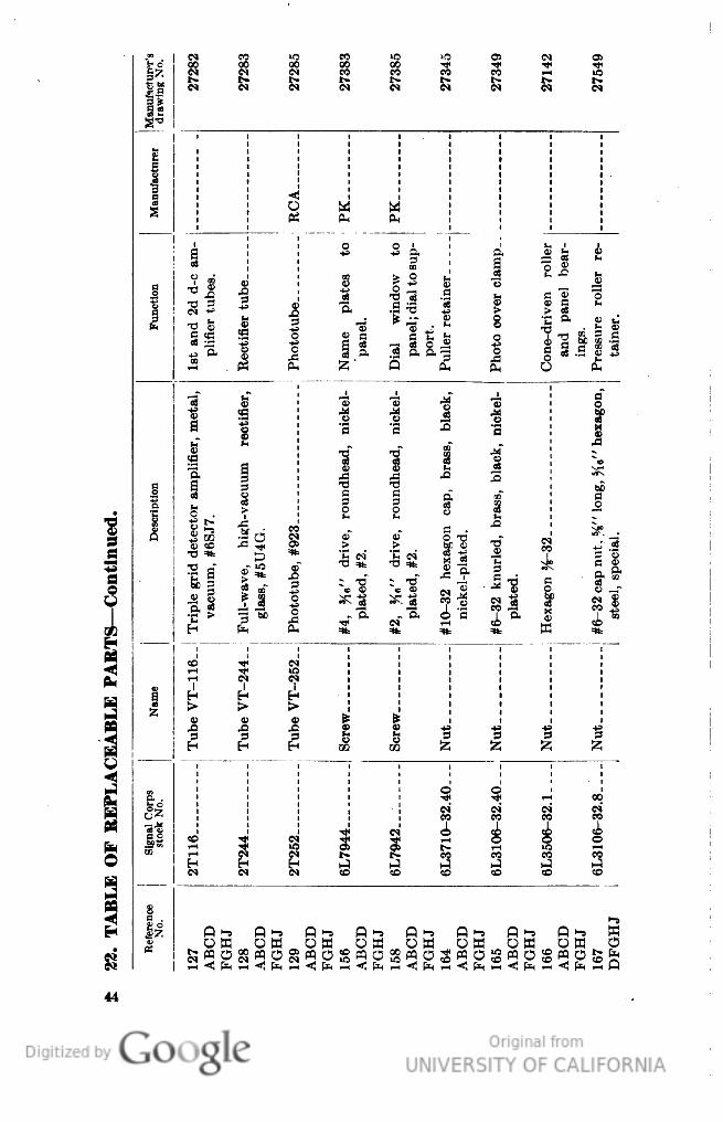
VI
CM
co
''•-
CO "f
>o
OS
CM
o
££
S
CO
04
00
IN
00 OC
g
21
S
1 S
t^
w
co tr
CO
t-
t-
11
W
IN fi
w
CM
tN
|
1
g
03
o
M ti
-
PH P-
,
O C
u. i
S
1
ft
= g
EC
S
o ^
9
CO >
o t-
J5
r~ -^
ffl
a
til ®
"c
H-* iJ
o
Functio
Rectifier tul
Phototube..
Is •§
1 •§
Photo cover
Cone-driven
and pane
_
Pressure ro
tainer.
ft .£
"3 ^
~ -4J
-— t-
•3.J £
|||
T: a>
*""
CD C
ings.
a s -:
3 — *
fc C
f'
*H*
1 1
i
a"
CD
O
1
o c
S
AS
B
'3 'c
3
"S
X
h
•a" -c
aT
CC
g
03?
C
S
tO
a
V Q
»Q
a
MTS
c
s
J3 j:
A
o
03
o
5 £
a
an
ft
.
.g
O .
>
I f
§
2
5
PS— Continued
p
Triple grid detect
va.um, #.,.
Phototube, #923_
V C.
* G) «
i^
1
Hexagon H-32...
#6-32 cap nut. 5^"
steel, special.
S K -2
- x ?•
O3 -t-1
I*
ll
.1 sl
O3 ™ O
f t ft
, ft i '5
^H
=it
|
1
1
=t^ ^tt
?r
^^
co
•4*
>o
Cu
I-H
ej<
l-H
I
I
H
n
H
H
H
i-9
x
«
to
S
'ff ft
i
£t
0) Q
«
«
4j
s
I
iS
a
:
H
H
03 a
Z
w
1
1
i
1
g3
1
s .
1
0
Q
^
00
H
ufc
1
g
tN
CM
CO
CO
CO
fe
CI ^
co
•rfI
c\i
•^ CO
;i-I
o
O
^
O
IB
tN
CTJ O
t^.
T-H
iH
CO
i— i
-
CO
CO
*W
£H
H
HH
h-1 h—
hJ
™
H
CM
CM
CD C£
CO
CD
cD
tc
-si
8
a .
s
Ix
W 0 S
O £ « O
Q
^ Q ^
Q ^ Q
S a
o g «
S OW
O (p W p
£
«
O
l-t ^
O
W OW
O W ^ O
o
•
os«p?
fa .5 <!
44
Genera
ted o
n 2
01
4-0
8-0
5 0
7:2
4 G
MT /
htt
p:/
/hd
l.hand
le.n
et/
20
27
/uc1
.b3
24
38
52
Public
Dom
ain
, G
oog
le-d
igit
ized
/
htt
p:/
/ww
w.h
ath
itru
st.o
rg/a
ccess
_use
#pd-g
oogle

00
IN
10
01
CM
O CN CO 00
•* CN rf O5
CO 1C CO CO
t*» t^ t^ t^
CN CN IN CN
CO
CN
tN
CN
1O
CO
CO
CO
SH
PH
O *
O
O
O
a
a
ft
§
a
fn •**
a
.2
£
i-
CD
0
OQ
S
flj CJ
.Xj
CO
'h
CC
O 0
a
C
*-
Flange, cone-d
roller.
o
T
g |
V O) CD
Supports ro
arm.
Roc ker-arm
port shaft.
c
c
l
b£>
o
b» 9» ^^
c3
o
a
•c
'c
J
1 S g
,
8
o -g c
"^ o "^
a a f
- ? 7 S
L,
- -~
T"
•i
~ as
g. 3
C Q)
p Cv
C
a
CD Q) *^i
>vj ^ C)
03 03 O
a
Jt
c
Cj (_.
S"
>, "o
o h
a
M
-^ c,
02 a:
8
H H ffl
e-
O
o
*
f
1
1
1
I
2
IS
H
N
A
H
J
"8
T
t-
"C
1
«.
*.
•S
^
M
^
f-i ^ |
M
w
i
i
1
t 1 i
N»
MX
44
4-J
M
*
i
g-
g"
a"
» n
3
«!-«
Q
Q
ft
'ft
'a
o
upport.
00
+*
6
o
ft
ft
d
t>
a
ft
>
hH
co Jj' 3
X
CB
>
o
5
O — C
O
O
> 3 cc
"S
2
f & 1
S
O
Q
c
<;
M»
V
|
3
w
|
o
ft
^ ^ CL
^00 • ^^ > >
O
>
~B
ft
c
c
c
O
CC
CD
t*
a.
S
o 6
0 &
0
^3
CC
M S
S
)
•*»
*w
g;
ft
CQ
CO
w S Si
I ^
„
CN
"S
HJ-
CD
ft
S
g
p
^
1
i
§
Q co R co;
^!
: S;
*
"s
T
OS
0 -r ° _r a
i
el
CO
7
t.
X
a
6J)
3,
V
u
a
o
1
1
C^, "S ^ "C O -
^ ^ S
1 * %>
=* 2
g
I
o
o
0
Q
J
Q
K
t vf
t S
1 PH
K
v e^-
1
1
ffl
I
(H h
i
•&
i
3
1
•Q
2
-1 -1
I
1
.S1
o
ft
•g
g
fli
1
ft
CQ
1
III
C
e
c
c
'fi
1
£
£
CC
ft
02
1
1
!
;
!
i
|
1
1
CN
CO
^
CN
^|
>O
CO
1
CN
IN
CN
CQ
co
CO
co
CO *O 1
«
d
T
iC
"9
O
I
i i i
CM
g
1C
O
g
O
O
•N
g
o
o
o
§
§
CN
S
CN
>c m cc
K
«
CO
2
^
^
^
^
^
^
^
hj H^J h^
CO CO CC
CC
CC
CC
CO
"*
**
"*
Til
"*
Tt-
"*
^ >-,
H,
H,
O ^ O
§Q §O i
oS^
o
O ^ 0 S
Q
>-5 Q >-»
o a
O
O
o
O
W 0 B
CO °
J p °c
"s
Q 1
0 2<S
O CQ
§3
S«
gffl
CO pg
O ^J
CO <<
o § « o
<! PH i-
CO <
co •<
fa co < fn
co <!
Genera
ted o
n 2
01
4-0
8-0
5 0
7:2
4 G
MT /
htt
p:/
/hd
l.hand
le.n
et/
20
27
/uc1
.b3
24
38
52
Public
Dom
ain
, G
oog
le-d
igit
ized
/
htt
p:/
/ww
w.h
ath
itru
st.o
rg/a
ccess
_use
#pd-g
oogle
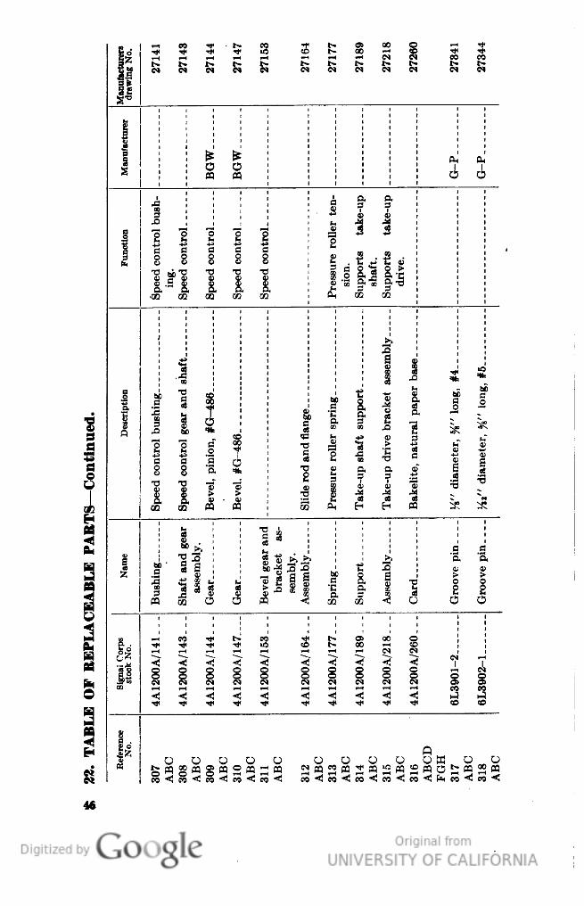
| =
3 3 5 5< 3 3
;t- O) 00 C
I^- 00 ~* CC
t
•*
Is
i^ t^ i^ t- t^ t^
ec
cc
3?
CM IN IN M CM CM
CM tN CM IN
CM
IN
S|
5
3
I-"" •-""'
a.
PH'
O
q
OS
0 0
C
.c
i g" §•
g
S I I
,Q
£j •§ 4
a
o
22222
8
c "c 'c ? S
g
a
So o o o
V V V V
t .•§«•§«
a
£
T3 fcjjo "C 13 "^ 1
3
S § §, o! S, .g
0) ft 3j Sj £ ^
oj 'Jl OH "^ O. -^
'CO 02 M CC 00
PH GO OQ
3
4*
S a
J3
1 •
%
DQ
g
9 1 i
fe
be
60 o S c
\4 C
o c
•a 1 1 *
J
-2
mtlnued.
1
0^ CO .Q "o
1^11
St
; U5X
2 2 g 1 |
ur
i-T
^
1 -1 S C
G « T»
|
c a "5 r;; *
8 8 '5- * 1
OJ O, &. C
Q
I
o
H s 3 M!
O
•"-•
U
"« ^ "* "3 q
• « 9 *3
•5
™
I
$ Q) t* T* "C
1 s 1 1
! ^
GO" GO" ffl ffl Sc
PH H H ff
a
ss
« H «
1
1
^4
§3 • 5 *
1
cu
'i « |
i
c
ft
i.f t • n *9 0) ^ Ji1 t—
'E
'a
M
z
c § S se^ 3 £
a
>
e
>
pa
o
«U
w
ffl L§ 0 0 ffl ^<
% & < i
O
O
w
1 1 1 1 1
1 1 1
1'
J
J C O ^ [sj pQ ^
I^ 05 OC C
a.
t. c
.
•* -^ -* Tt* iO CC
t- X — CC
5
=g
i 1 i 1 I i
< ^ ^' 5
§ S § §
=1
1
i
g
*
II
N N tN CN
c<1
a
0
<< ,5! <J< ^< <H <
^i «j< <J <
H
S
S
-* Tt. Tt< •* Tt- ^
•* •* ^ •*
«
CO
H
Q
O>
^°ooOOJOo°«0
O O 0 0
o W
0 O
•
OH
^2«2»^a^
™ S?
< c^ <
46
Genera
ted o
n 2
01
4-0
8-0
5 0
7:2
4 G
MT /
htt
p:/
/hd
l.hand
le.n
et/
20
27
/uc1
.b3
24
38
52
Public
Dom
ain
, G
oog
le-d
igit
ized
/
htt
p:/
/ww
w.h
ath
itru
st.o
rg/a
ccess
_use
#pd-g
oogle

co
1C O
CS CO
O) h.
CM OS
^*" N
OS
OS
c<
•G a
CQ
CO
1C
1C 1C
1C tT
co t^
!••
tM
CM C
M
CM IM
C M CM
t
t
O
i
1
m
i
a
I
"s
e
1 C
"3,
JZ
a.
! *
: S
'O .
^ rf,
K
j_
Q
£
Remove an
setscre ws
Remove an
set screw;
~
cc
capacito
3^3
"2 > &
< S^ S.
:
i
a
fri
«3 ~ «
i *
i
> H
t 60
i
i
1 "-
1
'
! =i
3
!
i 0
J
^
: e
|
s 1
>
i 1 O
1 (H
CD R
cO
S «
1O -C
1 'S
C/j I»
* OJ
2 S
i s.
-"tP.
*
JJ £
Q a
1 *
J
setscrew,
setscrew,
S |
_c -a
^J
C ti
is i°
"o.
1!
03 03
n
o
'C "5
tH
o
T3
c
o
"O C.
a «
c .2
m
3
c
§ o,
.2 .S
5
Q)
O 03
2 2
V
5
0 H
£ £
33 ffl
|
J
,
§ -a'
— fcH
i
0 a
i
i
g o
1
1
>. X
[-
X! be
a
43
i.
3 3
3
M -S
8
O
S S
E
•c I
C
r
1
C
OT C
O
S?
cj o
3)
t
C
^ 4?
c -»•
33 S
1O o
01 t-
CM OS
t
CM CO
1O «r
•* CM
i
'•'
1C 1C
1
i
C
g
O Q
Q C
Q P
O O
i§
jo
CM
CM «
CM C
CM CM
PS
M
^
< <
<3 <
<J <!
o
CC
•<*
Th •*
** "*
^ ^
8S
Q <->
0 W
WWW
w
w w
o o
W
O
o o o
o
03 P3 O
55 <! fa
o CD rK,
fllfilfi
lol
rt SH r
D co O co
Q
CO •< fa
«
Genera
ted o
n 2
01
4-0
8-0
5 0
7:2
4 G
MT /
htt
p:/
/hd
l.hand
le.n
et/
20
27
/uc1
.b3
24
38
52
Public
Dom
ain
, G
oog
le-d
igit
ized
/
htt
p:/
/ww
w.h
ath
itru
st.o
rg/a
ccess
_use
#pd-g
oogle

33. NAMES AND ADDRESSES OF MANUFACTURERS.
A Aerovox Corp., New Bedford, Mass.
AIR Atlantic India Rubber Works, Inc., Chicago, 111.
AM American Phenolic Corp., Chicago, 111.
ASC American Screw Co., Providence, R. I.
BGW Boston Gear Works, Inc., New York, N. Y.
B&H Bell & HoweU Co., Chicago, 111.
BUD Bud Radio, Inc., Cleveland, Ohio.
D Drake Electric Works, Inc., New York, N. Y.
EBY Hugh H. Eby, Inc., Philadelphia, Pa.
GE General Electric Co., Cleveland, Ohio.
GI General Industries Corp., Elyria, Ohio.
G-P Groove Pin Corp., Union City, N. J.
HBJ Howard B. Jones, Inc., Chicago, 111.
IRC International Resistance Co., Philadelphia, Pa.
K-K Kurz-Kasch, Inc., Dayton, Ohio.
LF Littlefuse, Inc., Chicago, 111.
M Frank W. Morse Co., New York, N. Y.
MA P. R. Mallory, Inc., Indianapolis, Ind.
M-Y Mallory-Yaxley Co., Indianapolis, Ind.
P-K Parker-Kalon Corp., New York, N. Y.
P-M Par-Metal Products Corp., Long Island City, N. Y.
RCA RCA Mfg. Company, Harrison, N. J.
SP Sprague Specialties, North Adams, Mass.
TH Thordarson Electric Manufacturing Co., Chicago, 111.
o
48
Genera
ted o
n 2
01
4-0
8-0
5 0
7:2
3 G
MT /
htt
p:/
/hd
l.hand
le.n
et/
20
27
/uc1
.b3
24
38
52
Public
Dom
ain
, G
oog
le-d
igit
ized
/
htt
p:/
/ww
w.h
ath
itru
st.o
rg/a
ccess
_use
#pd-g
oogle

Genera
ted o
n 2
01
4-0
8-0
5 0
7:2
3 G
MT /
htt
p:/
/hd
l.hand
le.n
et/
20
27
/uc1
.b3
24
38
52
Public
Dom
ain
, G
oog
le-d
igit
ized
/
htt
p:/
/ww
w.h
ath
itru
st.o
rg/a
ccess
_use
#pd-g
oogle