c00000-eng-06-tcn-0001 - pre-commissioning …€¦ · pre-commissioning includes all or a...
TRANSCRIPT
Document Number:
C00000-ENG-06-TCN-0001
C1 18/05/2013 Issued For Use RH SN RT
B1 03/04/2013 Issued For Review RH KF
A1 29/03/2013 Issued For Comment RH RT
Rev No. Rev Date Reason for Issue Prepared Checked Approved
Title: Pre-Commissioning Overview: Pipelines
Scale:
NTS
Size:
A4
Lang.
EN IMS

Doc Title: Pre-Commissioning Overview: Pipelines
Document. No: C00000-ENG-06-TCN-0001 Rev: C1 Date: 18/05/2013 Page: 2 of 20
REVISION RECORD SHEET
Revision Reason for Change Page Number(s) DCN Number
DISTRIBUTION AND CONTROL STATUS
Document Control Distribution Copy Number
Controlled
Uncontrolled
COPYRIGHT & CONFIDENTIALITY The information contained within this document is provided for the sole use of OFFSHORE ENERGY UK LIMITED personnel, authorised clients and subcontractors. All rights are reserved. No part of this document may be reproduced, stored in a retrieval system or transmitted in any form or by any means, electronic, magnetic tape, mechanical, photocopying, recording or otherwise without permission from OFFSHORE ENERGY UK LIMITED. Printed copies of this document are considered as uncontrolled.
Registered as Offshore Energy UK Limited in England, Company No. 07936973
E [email protected] W www.offshore-energy.co

Doc Title: Pre-Commissioning Overview: Pipelines
Document. No: C00000-ENG-06-TCN-0001 Rev: C1 Date: 18/05/2013 Page: 3 of 20
INDEX
1 SCOPE AND PURPOSE 4
2 REFERENCE DOCUMENTS 4
3 DEFINITIONS 4
3.1 PROJECT SPECIFIC TERMS 4 3.2 ABBREVIATIONS 4
4 PRECOMMISSIONING OVERVIEW 5
5 KEY INFORMATION 5
6 COMMON PIPELINE PRE-COMMISSIONING TERMINOLOGY 6
6.1 PIGGING OPERATIONS SUMMARY 6 6.2 FLOODING / FILLING SCENARIO 9 6.2.1 Cleaning 10 6.2.2 Gauging 11 6.2.3 Gauge Plate Condition Monitoring System 12 6.2.4 Calliper Pigs 12 6.2.5 Smart Gauge Pig 12
7 PIPELINE PRE-COMMISSIONING OPERATIONS 13
7.1 FLOODING, CLEANING AND GAUGING 13 7.1.1 Topside / vessel-based flooding spread 13 7.2 HYDRO-TESTING 16 7.3 LEAK TESTING 18 7.4 DEWATERING, CONDITIONING AND DRYING 18

Doc Title: Pre-Commissioning Overview: Pipelines
Document. No: C00000-ENG-06-TCN-0001 Rev: C1 Date: 18/05/2013 Page: 4 of 20
1 SCOPE AND PURPOSE
This document is a reference tool which describes the technical activities and challenges that can be encountered within pipeline and subsea pre-commissioning projects. Although the information is not exhaustive, it should work as an aid to assist with decisions about seeking technical expertise and guidance. Offshore Energy UK Limited can identify all aspects within pre-commissioning projects to ensure projects are safe, efficient, planned, controlled and managed.
2 REFERENCE DOCUMENTS
Ref Title Document Number
[1] DNV Submarine Pipeline Systems 2007 DNV OFS101 2007
3 DEFINITIONS
3.1 PROJECT SPECIFIC TERMS
Term Description
Barg Bar Gauge
Pinger Acoustic pig pingers are fitted to a pig as a location device
3.2 ABBREVIATIONS
Abbreviation Description
ASME American Society of Mechanical Engineers
DnV Det Norske Veritas
FPSO Floating Production, Storage And Offloading
ID Internal Diameter
IMS Integrated Management System
MEG Monoethylene Glycol
PIG Pipeline Internal Gauge
PLETs Pipeline End Terminations
PLRs Pig launcher / receivers
PSIG Pounds per square inch absolute (pressure relative to a vacuum rather than the ambient atmospheric pressure)
ROV Remotely Operated Vehicle
UV Ultra Violet Light

Doc Title: Pre-Commissioning Overview: Pipelines
Document. No: C00000-ENG-06-TCN-0001 Rev: C1 Date: 18/05/2013 Page: 5 of 20
4 PRECOMMISSIONING OVERVIEW
Pre-commissioning is generally considered to include the preparation and integrity verification of any system or structure upon completion of construction / installation and prior to commissioning. In relation to subsea pipeline or flow-line systems, these are often laid dry and include the facility to perform pre-commissioning activities. As part of the pipe lay process, the initiation and laydown heads may include suitable connections to allow launch and receipt of pre-loaded pigs. Other systems where pipeline end terminations or similar are installed these also generally allow for the provision and connection of subsea pig launchers and receivers to assist in pre-commissioning. Pre-commissioning includes all or a combination of operations to allow the pipeline or system to be cleaned, internally gauged, pressure tested and dewatered and / or dried. Sometimes there can be a final operation to prepare the pipeline for product by introducing an ‘inert’ nitrogen blanket in preparation for hydrocarbon production, however this is often considered to be a commissioning activity. De-commissioning can also be considered within the realms of the pre-commissioning discipline, importantly allowing preparation of existing systems or infrastructure for maintenance, shut-down or preservation. As in all areas of the oil and gas industry, safety is paramount. Many pre-commissioning activities involve pressure and stored energy in various forms. Chemicals are often used which creates a potentially hazardous environment and work place. Risk assessments are carried out for all activities for pre-commissioning and operations must follow a procedure that is approved by the client. In the event of any deviation or change, the same process must be followed. Barriers at a safe distance and signs to clearly identify the work being performed are a minimum precaution in all cases. There are numerous descriptions used for generic pre-commissioning methods; however, the information that follows can be used as a guide. Offshore Energy UK Limited can provide expertise in the area of pre-commissioning and should be contacted for further detailed or technical support.
5 KEY INFORMATION
In order to ensure an accurate technical understanding of any pipeline or process system, a number of generally available client or industry supplied key documents should be provided to allow review of the pre-commissioning activities:
Client specification / design criteria
Client scope of services / work
Client pre-commissioning philosophy
Client inspection and acceptance criteria
Pipeline / flow-line design code requirements (e.g. DNV / ASME)
Location and seasonal environment
Water depth
Pipeline dimensions, configuration, profile and alignment
Tie in details to structures (in line and external)
Internal diameter details including all components Offshore Energy UK Limited can provide technical expertise to allow clients to benefit from the operational advantages of pre-commissioning at every stage of a project. This service can include the preparation or review of key documents in order to achieve safe, compliant and timely project objectives. Our aim is to incorporate client expectations and the requirements of relevant codes in the design / construction programme. Additionally, we endeavour to provide support for any technical challenges. A technical review

Doc Title: Pre-Commissioning Overview: Pipelines
Document. No: C00000-ENG-06-TCN-0001 Rev: C1 Date: 18/05/2013 Page: 6 of 20
can be performed to ensure that the pre-commissioning / decommissioning elements are identified or clarified as necessary.
6 COMMON PIPELINE PRE-COMMISSIONING TERMINOLOGY
Flooding / filling
Cleaning
Progressive cleaning
Preservation
Gauging / calliper / internal geometry checking
Testing / Integrity Testing / Hydrotesting / Pressure Testing / Factory Acceptance Testing
Leak Testing
Dewatering
Conditioning
Drying
Nitrogen filling, inerting or purging
Nitrogen packing
De-commissioning
6.1 PIGGING OPERATIONS SUMMARY
Many of the above pipeline operations are performed using pipeline internal gauges (“pigs”). Pig design and product choice is highly variable depending on pipeline design (for example, line length, ID changes, bend radius, tees, wyes, and test pressure) and its application or intended use.
The available technologies are extensive and ever-changing; the range of products available from many of these suppliers is extensive and products can be highly technical. Therefore, Offshore Energy UK Limited discipline specialists add value with their up to date knowledge about industry suppliers. Pigs are normally used to remove debris, provide an interface or ensure a tight seal between any chosen propelling and filling medium. For example, most pipelines are laid in a dry condition and therefore contain only air in their initial ‘as laid’ state. To ensure that a successful filling, cleaning, gauging and testing operation can be performed, the use of mechanical pigs is essential. Depending on the filling and cleaning specification, single or multiple pigs (“pig trains”) can be used. The methods for storing and launching the pigs are numerous, and often temporary pig launcher / receivers are manufactured to facilitate this on a
Doc Title: Pre-Commissioning Overview: Pipelines
Document. No: C00000-ENG-06-TCN-0001 Rev: C1 Date: 18/05/2013 Page: 7 of 20
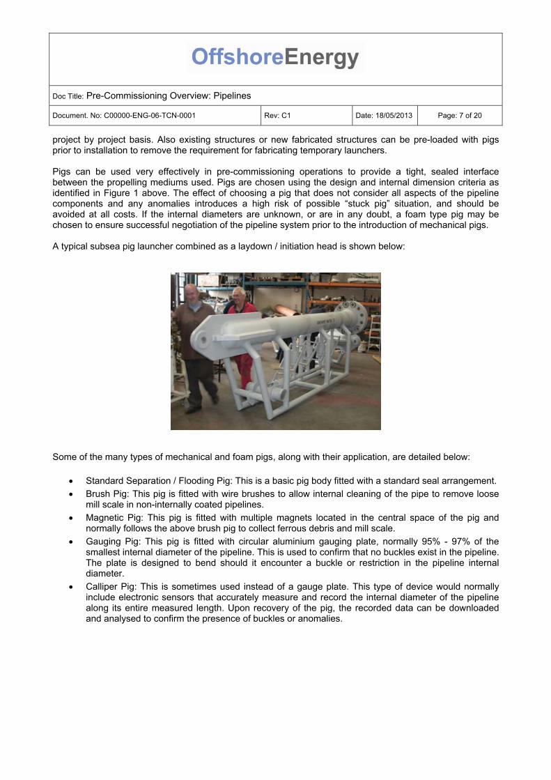
project by project basis. Also existing structures or new fabricated structures can be pre-loaded with pigs prior to installation to remove the requirement for fabricating temporary launchers. Pigs can be used very effectively in pre-commissioning operations to provide a tight, sealed interface between the propelling mediums used. Pigs are chosen using the design and internal dimension criteria as identified in Figure 1 above. The effect of choosing a pig that does not consider all aspects of the pipeline components and any anomalies introduces a high risk of possible “stuck pig” situation, and should be avoided at all costs. If the internal diameters are unknown, or are in any doubt, a foam type pig may be chosen to ensure successful negotiation of the pipeline system prior to the introduction of mechanical pigs. A typical subsea pig launcher combined as a laydown / initiation head is shown below:
Some of the many types of mechanical and foam pigs, along with their application, are detailed below:
Standard Separation / Flooding Pig: This is a basic pig body fitted with a standard seal arrangement.
Brush Pig: This pig is fitted with wire brushes to allow internal cleaning of the pipe to remove loose mill scale in non-internally coated pipelines.
Magnetic Pig: This pig is fitted with multiple magnets located in the central space of the pig and normally follows the above brush pig to collect ferrous debris and mill scale.
Gauging Pig: This pig is fitted with circular aluminium gauging plate, normally 95% - 97% of the smallest internal diameter of the pipeline. This is used to confirm that no buckles exist in the pipeline. The plate is designed to bend should it encounter a buckle or restriction in the pipeline internal diameter.
Calliper Pig: This is sometimes used instead of a gauge plate. This type of device would normally include electronic sensors that accurately measure and record the internal diameter of the pipeline along its entire measured length. Upon recovery of the pig, the recorded data can be downloaded and analysed to confirm the presence of buckles or anomalies.

Doc Title: Pre-Commissioning Overview: Pipelines
Document. No: C00000-ENG-06-TCN-0001 Rev: C1 Date: 18/05/2013 Page: 8 of 20
An illustration of calliper tools
High Seal Pig: These can be configured to include a multiple high seal or pressure withholding capability and can be used to act as a highly effective dewatering device, pressure barrier or interface.
Foam Pigs: These are available in various densities of foam (low, medium, high) and can be used in applications where the passage of the pig may be hampered or restricted due to unknown factors such as high debris presence, multiple or unknown diameters, or even as a means to dislodge a stuck pig. The sealing capability of foam pigs is not highly effective and therefore bypass occurs to a much higher degree than a mechanical pig (see below).
Intelligent Pig: These are highly advanced and sometimes multiple bodied (articulated) pigs that can be used to measure many of the pipeline internal parameters. These include advanced versions of the Calliper pigs mentioned above. Intelligent pigs are available that have multiple sensors to allow highly complex internal measurement and even Magnetic Particle Inspection of an entire pipeline.
Multi-diameter Mechanical Pig: These can be designed to negotiate multiple known diameters in pipelines. A highly effective sealing capability can be maintained using these devices as part of an engineered solution. All diameters must be known to ensure sealing characteristics are maintained.
Doc Title: Pre-Commissioning Overview: Pipelines
Document. No: C00000-ENG-06-TCN-0001 Rev: C1 Date: 18/05/2013 Page: 9 of 20
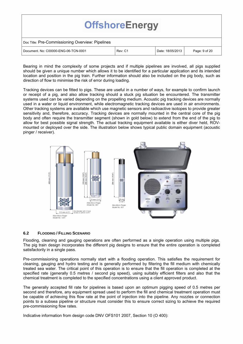
Bearing in mind the complexity of some projects and if multiple pipelines are involved, all pigs supplied should be given a unique number which allows it to be identified for a particular application and its intended location and position in the pig train. Further information should also be included on the pig body, such as direction of flow to minimise the risk of error during loading. Tracking devices can be fitted to pigs. These are useful in a number of ways, for example to confirm launch or receipt of a pig, and also allow tracking should a stuck pig situation be encountered. The transmitter systems used can be varied depending on the propelling medium. Acoustic pig tracking devices are normally used in a water or liquid environment, while electromagnetic tracking devices are used in air environments. Other tracking systems are available which use magnetic sensors and radioactive isotopes to provide greater sensitivity and, therefore, accuracy. Tracking devices are normally mounted in the central core of the pig body and often require the transmitter segment (shown in gold below) to extend from the end of the pig to allow for best possible signal strength. The actual tracking equipment available is either diver held, ROV-mounted or deployed over the side. The illustration below shows typical public domain equipment (acoustic pinger / receiver).
6.2 FLOODING / FILLING SCENARIO
Flooding, cleaning and gauging operations are often performed as a single operation using multiple pigs. The pig train design incorporates the different pig designs to ensure that the entire operation is completed satisfactorily in a single pass. Pre-commissioning operations normally start with a flooding operation. This satisfies the requirement for cleaning, gauging and hydro testing and is generally performed by filtering the fill medium with chemically treated sea water. The critical point of this operation is to ensure that the fill operation is completed at the specified rate (generally 0.5 metres / second pig speed), using suitably efficient filters and also that the chemical treatment is completed to the specified concentrations using a client approved product. The generally accepted fill rate for pipelines is based upon an optimum pigging speed of 0.5 metres per second and therefore, any equipment spread used to perform the fill and chemical treatment operation must be capable of achieving this flow rate at the point of injection into the pipeline. Any nozzles or connection points to a subsea pipeline or structure must consider this to ensure correct sizing to achieve the required pre-commissioning flow rates. Indicative information from design code DNV OFS101 2007, Section 10 (O 400):

Doc Title: Pre-Commissioning Overview: Pipelines
Document. No: C00000-ENG-06-TCN-0001 Rev: C1 Date: 18/05/2013 Page: 10 of 20
400 Cleaning and gauging 401 Cleaning and gauging may be combined with the initial flooding of the pipeline, be run as a separate operation, or be combined with the weld sphere removal after completion of hyperbaric tie-in. 402 Appropriate measures shall be taken to ensure that any suspended and dissolved substances in the fluid used for this operation are compatible with the pipe material and internal coating (if applied), and that deposits are not formed within the pipeline. 403 Water to be used for flooding should have a minimum quality corresponding to filtration through be filtered to remove suspended particles larger than a 50μm and filter, and should have an average content of suspended matters not exceeding 20 g/m3. 404 If water quality or the water source is unknown, water samples shall be analysed and suitable actions shall be taken to remove and/or inhibit harmful substances. 405 If water is to remain in the pipeline for an extended period of time, consideration shall be given to control of bacterial growth and internal corrosion by chemical treatment (see Sec.6 D302). 406 Added corrosion inhibitors, any chemical additives like oxygen scavengers, biocides, dyes, etc. shall be considered for possible harmful interactions selected to ensure full compatibility and their impact on the environment during and after disposal of the test water shall be considered. The information above is consistent with other design codes and provides basic guidance regarding pre-commissioning. It should be considered as the minimum standard for pre-commissioning activities on a new pipeline / system. Further specialist advice can be provided by Offshore Energy UK Limited. The use of chemicals is a common requirement to almost every pipeline flooding operation. It is important to ensure that this aspect of the work is performed accurately and in line with client requirements. Chemicals provide corrosion and bacterial protection; the concentration of chemicals to be injected will be specified by the client based on a protection / preservation period for the pipeline while it remains filled with seawater or fresh-water (as required). There is a small risk of finding installation damage to a pipeline or structure during the pre-commissioning phase and therefore, the chemical protection period is normally 12 months or longer. This ensures that sufficient protection time is allowed for any potential delay during repairs or remedial work. The use of dye is critical to the future pressure testing operation in that it provides a visible means of identifying a leak. The use of dye allows for ROV inspection of subsea pipelines / systems during the test period. The dye is generally fluorescent and allowance is made for a suitably compatible UV (black) light to be fitted to ROV for this purpose.
6.2.1 CLEANING
The cleaning of pipelines as part of the pre-commissioning operations is critical to ensure the quality of the product or service fluid for the pipeline. Furthermore, the potential for a clear and undamaged gauging operation could be affected by any larger debris material that is not removed from the pipeline. This is critical to construction activities and subsequently, to vessel time. When reviewing or investigating a cleaning specification, the following should be considered:
i) The client should accept a single pass cleaning operation which is based upon an approved operational procedure.
ii) Any stipulation allowing clients to reject a cleaning operation or require further cleaning should be avoided.
iii) The means or methods to prove a pipeline is clean are infinitely variable and therefore risk mitigation is paramount.

Doc Title: Pre-Commissioning Overview: Pipelines
Document. No: C00000-ENG-06-TCN-0001 Rev: C1 Date: 18/05/2013 Page: 11 of 20
iv) Internally coated pipelines should be given special consideration in relation to use of mechanical
cleaning pigs. The manufacturing materials for the pigs should be reviewed against the internal pipe coatings to ensure that no damage to the coating could be incurred.
A typical pipeline design code DNV OFS101 2007, Section 10 (O 407) relates to the cleaning operation: 407 The pipeline cleaning concept shall consider:
Protection of pipeline components and facilities (e.g. valves) from damage by cleaning fluids and pigs
Testing devices such as isolation spheres, etc.
Removal of substances that may contaminate the product to be transported
Particles and residue from testing and mill scale
Organisms and residue resulting from test fluids
Chemical residue and gels
Removal of metallic particles that may affect future inspection activities
6.2.2 GAUGING
Gauging of the pipeline or system is critical for a number of reasons. From a client perspective, gauging is normally performed to ensure that the pipeline is suitable for future pigging operations once production is commenced. This allows them to maintain production at optimum levels and ensures that they can launch and receive pigs to remove any build-up of wax or debris. From a construction aspect, it is important to confirm to the client that the pipeline or system has been laid and tied in without any damage or buckling. Should a gauge plate be received in a damaged state, it causes delays while the parties discuss the potential explanations and possible remediation. A standard gauging pig is normally fitted with an aluminium gauging plate. This is normally mounted toward the rear of the last pig in a flooding, cleaning, gauging train. A typical client specification in relation to the gauge plate is shown below: Gauge pigs shall be identical to cleaning pigs and the pigs shall include a gauge plate mounted in front of the last set of sealing discs with two sets of separate guiding and sealing discs. Gauge plates shall be machined aluminium 6 – 10mm thick and removable. The plate should have 8 radial slotted incisions at 45 degree intervals to allow the plate to buckle in the presence of a bore reduction, ovality or foreign debris. The leading edge shall be chamfered 45° to half the plate thickness. Each gauge plate shall be permanently marked with a unique identifier before insertion into the pipeline. Gauging pigs shall be fitted with a pig detector and its position in the line monitored. Gauge plates shall be 95% of the minimum nominal ID of the pipeline.
In the event pipeline or flowline system ID is not constant throughout, guide disks shall be slotted to ensure pig will negotiate ID variations. In such case, number of slots, number of guide disks and orientation of slots in the guide disk shall be determined by approved pig supplier.
In the event of Multi-ID lines, alternative methods for gauging to be proposed and accepted by client
Pipeline gauging is one of the more technical aspects of pigging. The client specification above describes what is considered to be the base case for gauging of a pipeline, but there are many other options available and they cover a wide range of electronic equipment and data recording capability. Below are a few examples of what is available, along with the advantages and disadvantages of each.

Doc Title: Pre-Commissioning Overview: Pipelines
Document. No: C00000-ENG-06-TCN-0001 Rev: C1 Date: 18/05/2013 Page: 12 of 20
6.2.3 GAUGE PLATE CONDITION MONITORING SYSTEM
A gauge plate monitoring system is an add-on to a simple gauge plate as described above. These systems utilise a modified gauge plate that has an electronic connection to an acoustic pinger. Damage to a gauge plate is detected by breaking a closed electrical circuit within the gauge plate that is connected to a pinger input. Any deflection of the gauge plate during the gauging run will result the electrical circuit being broken. This breakage will cause the pinger to change modes confirming damage to the gauge plate. The principle behind this system is that by using modified aluminium gauging plate attached to the pig, damage to the plate is indicated by the acoustic pinger. Initially, the pinger will be operating in a standby mode which means it will be pinging once every four seconds on a predetermined frequency. On detection of damage to the gauge plate, the pinger will switch to a mode where it will ping once every second and when used in conjunction with topside or vessel based pinger receiver, it provides remote monitoring. Alternatively, the receiver unit can be ROV-mounted. Advantages: This unit would work well in most straight forward situations where damage is unlikely to occur on a pipeline gauging run. It allows the pig receiver containing the gauge pig to remain in place on the seabed if the pinger status indicates no damage. This saves on operational time and therefore, vessel time. Disadvantages: The system does not show the possible location of damage. This is similar to a standard gauge plate. Pumping and pressure data would have to be closely reviewed to identify possible point of impact.
6.2.4 CALLIPER PIGS
Calliper pig is a technically advanced gauging tool. The unit works by using multiple spring loaded arms, spaced radically around the rear of the pig body, which feed information into calibrated sensors that measure and record any deflection as the tool runs through the pipeline. The arms are also fitted with odometer wheels to record distance travelled. The information received is extensive and provides more information than is necessary to obtain a gauging run acceptance. However, should a buckle or damaged pipe section be encountered the calliper tools can provide exact information as to the extent, orientation and location of the damage. They also provide a record of the entire line and therefore if multiple points along the pipelines are damaged all of them will be recorded, which is not the case with the other tools above. Advantage: Calliper pigs provide an extensive record of the internal pipe detail along entire length. Disadvantage: Units are not bi-directional; back-loading into heads often requires additional planning and cost. If pig launchers and receivers are to be preloaded with pigs, a tether system will be requires to switch the unit on during launch sequence.
6.2.5 SMART GAUGE PIG
Smart Gauge Pigs utilise the multiple sensor technologies generally used in the calliper type tools, but employ a spring loaded or hard polyurethane gauge disc instead of the individual sensor arms of a calliper. If the smart gauge disc is set to 95% of ID, the only time the unit will record data would be on any defect or anomaly that is greater than 5%. It deflects and returns to original position and therefore allows for multiple defects to be recorded. Advantage: Bi-directional. Records similar data to a Calliper Pg. They are less likely to be damaged due to polyurethane mounting of sensors in place of calliper arms. Disadvantage: Does not record all data along the full length of line. Does not have odometer and therefore to calculate exact location of any damage, the recorded data has to be compared against the pumping data.

Doc Title: Pre-Commissioning Overview: Pipelines
Document. No: C00000-ENG-06-TCN-0001 Rev: C1 Date: 18/05/2013 Page: 13 of 20
7 PIPELINE PRE-COMMISSIONING OPERATIONS
As described in the previous section, pre-commissioning operations generally follow the same sequence of events in order to prove the integrity of a pipeline or flow line system from completion of installation and prior to start up / commissioning. The following information summarises the operational methods used to complete the pre-commissioning operations. Prior to the commencement of operations for offshore projects, it is often a requirement to pre-load all required pigs into the pig launchers to meet the pipe lay schedule.
7.1 FLOODING, CLEANING AND GAUGING
Primary equipment and resources required to perform the flooding, cleaning and gauging operations is dependent on location, water depth, etc. Most sub-contractor service companies have the capability to perform flooding operations from either topside or a remote subsea location. The water depth, system diameter and fill volume will play an important role on the choice of equipment to be used for a given project. In shallow water (0-300m) a topside / vessel-based equipment spread is likely to be more efficient and cost effective as long as sufficient deck space is available to locate the equipment. All equipment used should be suitably designed and fully certified for offshore operations and additional care should be taken if hazardous environment (Zone 2) is identified for equipment. Consideration should be given to ensure that contingency capabilities and spare parts are available for all equipment. A brief summary of the most common equipment options is provided below.
7.1.1 TOPSIDE / VESSEL-BASED FLOODING SPREAD
In general, topside flooding equipment will be modular and sized to suit the maximum requirements of the project. Almost all topside spreads will include the following: Break tank
Sized to ensure at least five (5) minutes of flow at the required minimum rate Weight allowances for deck plans must consider the tank in a full condition
Fuel tank
May be necessary depending on expected duration of continuous operation and the fuel tank size of any diesel driven equipment
Flooding pump(s)
Sized to ensure sufficient flow to achieve the minimum pigging speed and the maximum expected pressure
Filter skid
Sized to be capable of flow rate at maximum requirement for intended operations Chemical injection skid
Sufficient numbers of pumps should be included to cover all types of chemicals to be pumped plus 100% spare pump spares and contingency pumps
Sized to be capable of operating at the required injection pressure and at the maximum flow of the flooding system. Concentration of chemicals is normally in parts per million and can be easily calculated using the PPM requirements compared to pump flow rates.
A chemical storage container may also be required and allowance must be made for a chemical storage area

Doc Title: Pre-Commissioning Overview: Pipelines
Document. No: C00000-ENG-06-TCN-0001 Rev: C1 Date: 18/05/2013 Page: 14 of 20
Hose reel / over-boarding chute
The hose reel should be capable of storing and deploying sufficient hose for the water depth plus additional remaining wraps on the reel itself
Hose support and winching during deployment and recovery should be clearly defined in relation to responsibility
Scope of supply for hose end connections and limits of systems should be established to ensure that adaptors, hot stabs and connectors are identified and responsibility defined
Test / control cabin
Must be suitably powered and clean environment with facility to mount pressure gauges, recorders and flow metering displays. The cabin should be set up to allow for all operations to be controlled from this point. Hand held radios should be included in sufficient number to ensure good communication during operations.
Pressure / Flow Metering System
Topside equipment should include a full range of pressure and flow measurement and recording equipment
Flooding equipment maximum pressure should not be less than 50% and not exceed 90% of the range of the instrumentation
All expected flow conditions should be within the range of the flow metering system The chemical injection system should include a means of accurately measuring and verifying the
injection value in parts per million
Hoses and manifolds Hoses and manifolds will normally be mobilised in half-height containers. Once the equipment is set
up and established on site, this container can be left onshore or stored elsewhere if space is restricted.
Below is a typical example of a vessel based flooding spread layout:
Subsea / remote flooding skid

Doc Title: Pre-Commissioning Overview: Pipelines
Document. No: C00000-ENG-06-TCN-0001 Rev: C1 Date: 18/05/2013 Page: 15 of 20
As an alternative to the topside based equipment spread described above, some companies can provide a subsea based or remote flooding and testing system. This is advantageous where restricted deck space is available and also for deep water operations (+300m), where longer hoses make handling and deployments more difficult and less effective. The remote systems are highly effective where the pipe-lay operation has been completed with the pipe remaining empty. The design of the units allows for three main operations to be performed:
Unassisted flow (no intervention required once operation is commenced)
Assisted flow (ROV hydraulic supply needed to power the remote unit)
Testing Pump Facility (additional inboard pump allows for testing function using ROV hydraulic supply)
The remote unit is pre-filled filled with the relevant chemicals and set up on deck for the intended pipeline operation. It is then deployed to within a few metres of the connection point to the pipeline / pig launcher. A hose or loading arm is installed from the remote unit to the pipeline connection. The ROV lands itself on a control bed on top of the remote unit; this allows the ROV to operate valves to initiate operation. For unassisted flow, the ROV will connect a hydraulic supply from its own hydraulic system to power the remote unit boost pump. Unassisted flow is created by connecting the remote module to the pipeline connector or pig launcher. Unassisted flow uses the ambient static head at water depth to provide sea water flow into the remote module and onward into the pipeline. The remote module is basically a filtration, chemical injection, flow control system. The differential pressure between the empty pipeline and subsea ambient is used as a driving medium for the flooding / pigging operation. During these operations the flow will be equalised with static head and at that point, assisted flow is required to complete the operation. This situation normally occurs when the operation is 90% complete. Assisted flow requires the ROV to land on the control bed on top of the remote unit and connects its hydraulic system via a stab connector. This allows the ROV hydraulic power to drive a boost pump built into the remote unit. The display on the remote unit indicates the pumping parameters, allowing the ROV to complete the operation using this method. This method can also be used to drive a hydro-test pump built into the remote unit to allow subsea testing operations to be completed. The illustration below shows a typical remote unit (right) connected to a flowline PLET:
Doc Title: Pre-Commissioning Overview: Pipelines
Document. No: C00000-ENG-06-TCN-0001 Rev: C1 Date: 18/05/2013 Page: 16 of 20
7.2 HYDRO-TESTING
In order to comply with the design code and industry standards, all pipelines and subsea systems associated with pipelines are hydro-tested and the pressure held for approximately 24 hours. The basis of this test is to ensure that the integrity of the system is complete, and that its pressure retaining capabilities exceed the intended operating parameters of the pipeline or system. A common specification for the testing pressure is 1.25 or 1.5 times the design pressure of the pipeline. The hold period of 24 hours allows sufficient time for even small leaks to be evident as a pressure drop. Other factors that can affect the pressure in the pipeline such as temperature change and elevation are also considered. The use of valves to isolate a system is generally avoided as this increases the leak potential increases significantly. Due to the fact that the hydro test is generally achieved at above the design pressure, precautions are taken to ensure that the pipeline is pressurised, monitored and given time to stabilise at key stages during the pressurisation phase. Typically the pressurisation rate of a pipeline system is 1 Barg per minute up to 95% of test pressure. From 95 – 100% it is reduced to 0.1 Barg. This change in pressurisation rate is known to assist in stabilisation of the test once the final hold pressure is attained. The accuracy of pressure monitoring equipment is critical during a hydro test and therefore, the accuracy and sensitivity of the equipment is much higher than for other pre-commissioning activities such as flooding or dewatering. As previously described, the flooding of a pipeline using pigs is critical to the testing operation in order to avoid any air content during hydro testing operations. High air content is an unacceptable and potentially dangerous situation during a pressure test as the compressible nature of air would cause massive damage should a rupture or failure occur during a hydro-test. Typically a maximum 0.1% air content is set as the acceptance criteria. The air content is measured at around 35% of test pressure and always above a pressure of 35 Barg (500PSIG). Once the system or pipeline is at test pressure, a hold period commences to ascertain the stability of the system. After pressurisation, it often takes a few hours or more for the pressure to stabilise and allow the 24hour hold period to commence. During the hold period, data is recorded to ensure that the subsea temperature and pipeline pressure is known for the entire period. To achieve an acceptable test, the pressure must be maintained for a 24 hour period without any unexplainable pressure drop. In other words no leaks are allowed, and therefore if a pressure change occurs it must be accountable by change in temperature or other explanation. Throughout the test period, checks for leaks are carried out at all locations. In relation pipelines it is not often that leaks are found along the pipeline length. In most cases, any leaks are found at tie-in in or structure locations. Time should be allowed to perform leak checks in these locations. Once a successful test period is achieved and client acceptance has been obtained, depressurisation is commenced to reduce the pressure in the system back to zero. If leaks are indicated and subsequently located during the test period, the leaking section must be isolated and depressurised before any remedial works are completed. If isolation is not possible, the entire system must be depressurised.

Doc Title: Pre-Commissioning Overview: Pipelines
Document. No: C00000-ENG-06-TCN-0001 Rev: C1 Date: 18/05/2013 Page: 17 of 20
The illustration below shows a typical vessel-based hydro-testing spread:
As previously described, it is also possible to utilise remote subsea equipment to perform a pressure test. This utilises the ROV hydraulic power to energise the hydraulic pressurising pump and avoids the requirement for long down lines. It also allows the vessel to move to other work during the hold period. Below is an illustration of a subsea test arrangement using remote testing equipment:

Doc Title: Pre-Commissioning Overview: Pipelines
Document. No: C00000-ENG-06-TCN-0001 Rev: C1 Date: 18/05/2013 Page: 18 of 20
7.3 LEAK TESTING
In order to prepare systems for pre-commissioning operations, it is often a requirement to break the integrity of associated pipe work to create isolations or in some cases to perform further tie in work after completion of a 24-hour hydro test. In these cases, any disturbed or additional connections must be leak-tested to ensure that the integrity of the entire system is maintained. Subsea structures, manifolds and other assembled equipment that contains multiple connections will also be subject to leak testing once the assembly process has been completed. Leak testing is treated differently to the 24 hour integrity testing as detailed in the previous section. The basis of a leak test is to visually check for external leaks whilst maintaining the test pressure. Often the hold period for a leak test will be one hour but this will be dependent on the complexity of the system. In some cases, a leak test period of six hours or more may be required. Leak testing operations normally include valve isolations and therefore, a completely leak tight system is often not possible. This is acceptable by maintaining the pressure at or above the test pressure during the entire hold period. If valves are passing through the cavities, it is difficult to quantify this and therefore, it is not part of the acceptance criteria (which is normally ‘no visible leaks whilst maintaining the system above test pressure’). Equipment and instrumentation for leak testing is generally very similar to that used for hydro-testing. Pressurisation and depressurisation rates will often be less stringent depending on the complexity of the system. In all cases, during a pressure test situation any leaks must be isolated and the pressure vented prior to any remedial works being carried out. If the individual section cannot be isolated, the entire system must be depressurised. Client acceptance must always be obtained prior to depressurisation.
7.4 DEWATERING, CONDITIONING AND DRYING
The requirements for dewatering, conditioning or drying are normally specified by the client. Dewatering operations will utilise a pig train design that is based on the level of dryness required by the client. If the dryness criteria is not relevant or of significant importance, a single pig may be used to allow bulk dewatering. In this situation, compressed air equipment will be used to complete the operation. The choice and sizing of the compressors should consider the expected dewatering pressure and the required dewatering velocity for the pig(s). The presence of a static head should always be reviewed when dewatering will be carried out. Often in an offshore situation, the highest pressure required during the dewatering operation will be the final pressure required to propel the pigs from the bottom of a riser system up to a platform or Floating Production, Storage and Offloading vessel. The static head applied in this instance, as well as the other factors of friction loss in hoses, water depth, etc., will dictate the output specification of the compressed air / dewatering package. If there is a potential for hydrate or if the system is intended for use with hydrocarbon gas, there will be a requirement to dewater and condition the system. In this situation, the dewatering spread will be required to produce dry air; generally the dryness will be -30 to -40°C. Anything dryer will require specialist drying equipment or nitrogen gas instead of compressed air. The conditioning element of the dewatering process is achieved with an antifreeze product within a pig train, such as methanol or glycol. A common antifreeze product is monoethylene glycol (MEG). Antifreeze products create an interface during the dewatering process between the chemically treated seawater in the pipeline and the propelling medium of the dewatering pig train. Typically, two or three slugs of MEG will be used to ensure that a minimum water presence remains within the pipeline after dewatering. By using this method, any liquid film that remains on the pipe wall from the dewatering operation will be a MEG film and ensure hydrate inhibition.

Doc Title: Pre-Commissioning Overview: Pipelines
Document. No: C00000-ENG-06-TCN-0001 Rev: C1 Date: 18/05/2013 Page: 19 of 20
A typical dewatering spread will consist of three or five pigs depending on the length of pipeline and the required residual concentration of hydrate inhibition. A sample five pig subsea to subsea dewatering / conditioning train is below:
o Seawater
Pig 1 o Dry Air / Nitrogen Slug
Pig 2 o MEG Slug
Pig 3 o MEG Slug
Pig 4 o MEG Slug
Pig 5 o Dry Air / Nitrogen
The number of pigs specified and should be considered at the review stage to ensure that allowance is made for the provision of the materials, chemicals, storage, deck space, etc., as well as the schedule or time allowance to complete the pig loading, launching and dewatering / conditioning operations. Below is a typical example of a vessel-based dewatering and conditioning arrangement:
In some instances, client requirements may include the use of nitrogen as well as dry, compressed air dewatering. The introduction of nitrogen into the conditioning scenario will add to the level and type of equipment required. If the volume of nitrogen is very small, it is possible that nitrogen bottles or quads may be sufficient. For pipelines or flow lines there are basically two options for nitrogen gas injection: cryogenic nitrogen and membrane nitrogen.

Doc Title: Pre-Commissioning Overview: Pipelines
Document. No: C00000-ENG-06-TCN-0001 Rev: C1 Date: 18/05/2013 Page: 20 of 20
Option 1 - Cryogenic (liquid) nitrogen is stored in special offshore rated tanks, and requires careful handling and storage considerations. The liquid is extremely cold in its liquid form (-196°C); suitable deck and ventilation precautions must be taken to ensure the safety of the vessel and its personnel. Nitrogen is inert and therefore free of oxygen, so enclosed spaces and restricted air flow should be a consideration and access should be restricted accordingly. Open vessel deck areas would not normally pose any problems once suitable deck covering (in the form of scaffold boards and a watertight layer) is installed. Any high potential high volume discharge or venting points should be routed to a safe area away from areas where personnel are working. Cryogenic nitrogen pumps are used to inject the nitrogen and along with the nitrogen storage tanks, must be factored into deck plans, equipment spread rates, etc. Liquid nitrogen storage tanks generally hold an equivalent of 150,000 – 250,000 standard cubic feet (4.300 - 7,000 SM³) of gas and during the dewatering operations, tanks movements may be necessary. If large volumes of nitrogen are needed, the use of membrane nitrogen may be more appropriate. The logistics of moving multiple loads of nitrogen, as well as the weather dependency of rotating full and empty tanks from an onshore nitrogen supply point, cost escalation and the potential for delay, make liquid nitrogen less suitable in these circumstances. Option 2 – Membrane nitrogen uses a completely different process for producing and delivering the nitrogen gas. It is produced via membrane units which are normally part of a containerised unit. The basis of the membrane process requires a supply of compressed air at the inlet. The multiple membrane packages extract the other elemental constituents of the compressed air retaining only the nitrogen at 95% purity. As a rule of thumb, the compressed air delivery to a membrane package will be halved at the outlet.