c06. s05. p02 – p12 gypfloor silent - british...
TRANSCRIPT

C06.S05.P02–P12 GypFloorsilent
IncludingC06.S01.P02–P08
Floorsandceilingsintroduction
!Thissectionincludesupdatedinformation,addedsinceitwasfirst
publishedinDecember2015.
Last updated 16/12/2016

british-gypsum.com
Floors and ceilingsThis section details floors and ceilings systems which cover a multitude of performance requirements in all sectors
C06
Intr
odu
ctio
nFl
oors
an
d ce
ilin
gs

C06. S01. P02 0115 945 6123 [email protected]
C06Introdu
ctionFloors an
d ceilings
Floors and ceilings
British Gypsum offers a full range of specifications from simple plasterboard ceilings through to a range of gypsum-based, acoustic suspended ceilings and lay-in grid systems. They cover all building categories, including private and social housing, apartments, healthcare, educational facilities, recreational and industrial properties in both new-build and refurbishment and can satisfy the most demanding performance requirements.
When specifying floor and ceiling solutions, a number of performance characteristics are normally used to determine the required solution. Depending on the project or construction type, these performance parameters could be set by minimum regulatory standards, or a client or customer requirement, for buildings that offer the highest standards of performance and comfort.
Our quick-reference floors and ceilings system guide, below, allows you to simply select the performance categories of interest and identify the British Gypsum floor and ceiling systems which best satisfy your project requirements.
Fire
performancemins
Installed cavity depth
mm
Acoustic performance
System PageRwdB Rw + C
trdB Ln,w
dB αw
30 - 120 ≥100 56 - 66 50 - 55 68 - 50 0.35 - 0.85 CasoLine mf C06. S02. P02
- ≥100 - - - 0.35 - 0.852 CasoLine curve C06. S03. P02
30 - 90 25 - 175 52 - 63 50 66 - 55 0.35 - 0.85 GypLyner universal C06. S04. P02
30 - 90 - 54 - 63 47 - 51 63 - 55 - GypFloor silent1 C06. S05. P02
30 - 120 - 36 - 66 50 - 55 78 - 48 - Timber floors C06. S06. P02
30 - 60 - - - - - Cavity fire barriers C06. S07. P02
1 Where the floor can only be accessed from above, the fire and accoustic performances can be upgraded with the GypFloor silent system.2 Indicative first test performance only.

C06. S01. P03 british-gypsum.com
C06
Intr
odu
ctio
nFl
oors
an
d ce
ilin
gs
Good practice specification guidance
British Gypsum’s systems are designed and tested to meet every performance requirement and are fully supported by our SpecSure® lifetime system warranty.
This means that when our systems are installed following our guidance they will achieve every performance claim we make, and if they don’t then we’ll put it right. To maximise the performance achieved on site, consider the following good practice specification guidance:
— Consider flanking transmission at the design stage and ensure construction detailing is specified to eliminate, or at least to minimise, any downgrading of the acoustic performance. The sound insulation values quoted in system performance tables are laboratory values and the practicalities of construction will mean that acoustic performances measured in the laboratory will be difficult to achieve on site
— Small openings such as gaps, cracks or holes will conduct airborne sounds and can significantly reduce the sound insulation of a construction. For optimum sound insulation a construction must be airtight
— When designing spaces requiring separation by sound insulating floors and ceilings abutting structural steelwork, consideration should be given to the potential loss of sound insulation performance through the steelwork
Acoustic performance
Table1–RecommendedlaboratoryperformancetomeetrequirementsofBuildingRegulationsApprovedDocumentE(EnglandandWales)
Where applicable Minimum airborne
sound insulation
DnT,w
+ Ctr (site test result)
Recommended
performance Rw
+ Ctr
(laboratory test result)
Maximum impact
sound transmission
L’nT,w
(site test result)
Recommended
performance
Ln,w
(laboratory test result)
Separating walls between new homes 45dB 54dB - -
Separating walls between purpose-built
rooms for residential purposes
43dB 52dB - -
Separating walls between rooms created by
a change of use or conversion
43dB 52dB - -
Separating floors between new homes and
purpose-built rooms for residential purposes
45dB 54dB 62dB 57dB - 52dB
(depending on
construction method)
Separating floors between rooms created by
a change of use or conversion
43dB 52dB 64dB 59dB - 54dB
(depending on
construction method)
Table2–RecommendedlaboratoryperformancetomeetrequirementsofTechnicalHandbookSection5(Scotland)
Where applicable Minimum airborne
sound insulation
DnT,w
(site test result)
Recommended
performance Rw
(laboratory test result)
Maximum impact
sound transmission
L’nT,w
(site test result)
Recommended
performance
Ln,w
(laboratory test result)
Separating walls between new homes,
purpose-built rooms for residential purposes
and conversions (not including traditional
buildings1)
56dB 63dB - -
Separating walls between rooms created by
a change of use or conversion (traditional
buildings1)
53dB 60dB - -
Separating floors between new homes,
purpose-built rooms for residential purposes
and conversions (not including traditional
buildings 1)
56dB 63dB 56dB 51dB - 46dB
(depending on
construction method)
Separating floors between rooms created by
a change of use or conversion (traditional
buildings1)
53dB 60dB 58dB 53dB - 48dB
(depending on
construction method)
1 Definition of traditional buildings.
A building or part of a building of a type constructed before or around 1919:
a) using construction techniques that were commonly in use before 1919; and
b) with permeable components, in a way that promotes the dissipation of moisture from the building fabric.

C06. S01. P04 0115 945 6123 [email protected]
C06Introdu
ctionFloors an
d ceilings
Gyptone quattro 46 (plenum depth 400mm)
Gyptone quattro 46 (plenum depth 400mm plus
100mm Isover Spacesaver Ready-Cut)
Practical absorption coefficient α
p
125 250 500 1k 2k 4k αW
AC1 NRC2
0.65 0.60 0.55 0.45 0.40 0.35 0.45(L) D 0.50
0.60 0.60 0.65 0.55 0.45 0.40 0.50(L) D 0.55
Gyptone quattro 42 (plenum depth 50mm)3
Practical absorption coefficient α
p
125 250 500 1k 2k 4k αW
AC1 NRC2
0.20 0.40 0.60 0.60 0.45 0.40 0.50 D 0.55
Gyptone quattro 41 (plenum depth 187mm)
Practical absorption coefficient α
p
125 250 500 1k 2k 4k αW
AC1 NRC2
0.50 0.70 0.80 0.70 0.60 0.55 0.65 C 0.70
System reference C10A014
C10A015
QUATTRO 46 Sound absorption coefficient αp
0.0
0.2
0.4
0.6
0.8
1.0
125 250 500 1000 2000 4000
Prac
tica
l abs
orpt
ion
coe
ffic
ien
t α p
Frequency (Hz)
Gyptone performance
Table 3 – Sound absorption data for Gyptone boards
1 AC - Absorption Class.2 NRC - Noise Reduction Coefficient.3 Due to installation limitations the minimum cavity size that can be constructed with CasoLine mf or CasoLine curve system is 100mm. The sound absorption
performance for these systems is estimated to be equivalent to that of the same system built with a 50mm plenum.
All products have been tested to BS EN 20354 and ISO 354. The single figure rating practical sound absorption coefficient αw
is calculated in accordance
with EN ISO 11654. Suffix letters indicate where performance is limited at either low, medium or high frequencies.
QUATTRO 41
System reference C10A091
Sound absorption coefficient αp
0.0
0.2
0.4
0.6
0.8
1.0
125 250 500 1000 2000 4000
Prac
tica
l abs
orpt
ion
coe
ffic
ien
t α p
Frequency (Hz)
QUATTRO 42 Sound absorption coefficient αp
0.0
0.2
0.4
0.6
0.8
1.0
125 250 500 1000 2000 4000
Prac
tica
l abs
orpt
ion
coe
ffic
ien
t α p
Frequency (Hz)
System reference C10A110

C06. S01. P05 british-gypsum.com
C06
Intr
odu
ctio
nFl
oors
an
d ce
ilin
gs
Gyptone sixto 63 (plenum depth 200mm)
Practical absorption coefficient α
p
125 250 500 1k 2k 4k αW
AC1 NRC2
0.35 0.60 0.70 0.60 0.55 0.55 0.60 C 0.60
Gyptone line 6 (plenum depth 400mm)
Gyptone line 6 (plenum depth 400mm plus
100mm Isover Spacesaver Ready-Cut)
Practical absorption coefficient α
p
125 250 500 1k 2k 4k αW
AC1 NRC2
0.70 0.65 0.60 0.50 0.40 0.35 0.45(L) D 0.55
0.70 0.70 0.65 0.65 0.50 0.45 0.55(L) D 0.65
Gyptone quattro 47 (plenum depth 400mm)
Gyptone quattro 47 (plenum depth 400mm plus
50mm Isover Acoustic Partition Roll (APR 1200))
Practical absorption coefficient α
p
125 250 500 1k 2k 4k αW
AC1 NRC2
0.45 0.50 0.45 0.40 0.30 0.25 0.35(L) D 0.40
0.50 0.55 0.50 0.40 0.30 0.30 0.40(L) D 0.45
Gyptone performance (continued)
Table 3 (continued) – Sound absorption data for Gyptone boards
System reference C10A016
C10A017
QUATTRO 47 Sound absorption coefficient αp
0.0
0.2
0.4
0.6
0.8
1.0
125 250 500 1000 2000 4000
Prac
tica
l abs
orpt
ion
coe
ffic
ien
t α p
Frequency (Hz)
System reference C10A001
C10A002
LINE 6 Sound absorption coefficient αp
0.0
0.2
0.4
0.6
0.8
1.0
125 250 500 1000 2000 4000
Prac
tica
l abs
orpt
ion
coe
ffic
ien
t α p
Frequency (Hz)
System reference C10A115
SIXTO 63 Sound absorption coefficient αp
0.0
0.2
0.4
0.6
0.8
1.0
125 250 500 1000 2000 4000
Prac
tica
l abs
orpt
ion
coe
ffic
ien
t α p
Frequency (Hz)
1 AC - Absorption Class.2 NRC - Noise Reduction Coefficient.
All products have been tested to BS EN 20354 and ISO 354. The single figure rating practical sound absorption coefficient αw
is calculated in accordance
with EN ISO 11654. Suffix letters indicate where performance is limited at either low, medium or high frequencies.

C06. S01. P06 0115 945 6123 [email protected]
C06Introdu
ctionFloors an
d ceilings
Rigitone performance
Table 4 – Sound absorption data for Rigitone boards
1 AC - Absorption Class.2 NRC - Noise Reduction Coefficient.3 Due to installation limitations the minimum cavity size that can be constructed with CasoLine mf or CasoLine curve system is 100mm. The sound absorption
performance for these systems is estimated to be equivalent to that of the same system built with a 50mm plenum.
All products have been tested to BS EN 20354 and ISO 354. The single figure rating practical sound absorption coefficient αw
is calculated in accordance
with EN ISO 11654. Suffix letters indicate where performance is limited at either low, medium or high frequencies.
8-15-20 SUPER Sound absorption coefficient αp
Prac
tica
l abs
orpt
ion
coe
ffic
ien
t α p
Frequency (Hz)
System reference C10A058
C10A059
C10A069
Rigitone 8-15-20 super (plenum depth 50mm)3
Rigitone 8-15-20 super (plenum depth 200mm)
Rigitone 8-15-20 super (plenum depth 200mm plus
50mm Isover Frame Batt 32)
Practical absorption coefficient α
p
125 250 500 1k 2k 4k αW
AC1 NRC2
0.15 0.40 0.70 0.75 0.45 0.40 0.50(M) D 0.55
0.35 0.75 0.75 0.55 0.40 0.30 0.45(LM) D 0.60
0.60 0.85 0.80 0.65 0.45 0.30 0.45(LM) D 0.70
Rigitone 8/18 (plenum depth 50mm)3
Rigitone 8/18 (plenum depth 200mm)
Rigitone 8/18 (plenum depth 200mm plus 50mm Isover Frame Batt 32)
Practical absorption coefficient α
p
125 250 500 1k 2k 4k αW
AC1 NRC2
0.10 0.30 0.65 0.85 0.55 0.30 0.50(M) D 0.55
0.35 0.75 0.90 0.60 0.50 0.40 0.55(LM) D 0.70
0.60 0.95 0.95 0.80 0.70 0.50 0.70(LM) C 0.85
System reference C10A036
C10A037
C10A060
8/18 Sound absorption coefficient αp
0.0
0.2
0.4
0.6
0.8
1.0
125 250 500 1000 2000 4000
Prac
tica
l abs
orpt
ion
coe
ffic
ien
t α p
Frequency (Hz)
System reference C10A125
C10A124
C10A126
8/18 Q Sound absorption coefficient αp
0.0
0.2
0.4
0.6
0.8
1.0
125 250 500 1000 2000 4000
Prac
tica
l abs
orpt
ion
coe
ffic
ien
t α p
Frequency (Hz)
Rigitone 8/18 q (plenum depth 50mm)3
Rigitone 8/18 q (plenum depth 200mm)
Rigitone 8/18 q (plenum depth 200mm plus
25mm Isover Acoustic Partition Roll (APR 1200))
Practical absorption coefficient α
p
125 250 500 1k 2k 4k αW
AC1 NRC2
0.15 0.25 0.60 0.85 0.65 0.50 0.55(M) D 0.60
0.40 0.65 0.80 0.60 0.55 0.50 0.60 C 0.65
0.40 0.70 0.85 0.80 0.80 0.70 0.80 B 0.80
0.0
0.2
0.4
0.6
0.8
1.0
125 250 500 1000 2000 4000

C06. S01. P07 british-gypsum.com
C06
Intr
odu
ctio
nFl
oors
an
d ce
ilin
gs
Rigitone performance (continued)
Table 4 (continued) - Sound absorption data for Rigitone boards
1 AC – Absorption Class.2 NRC – Noise Reduction Coefficient.3 Due to installation limitations the minimum cavity size that can be constructed with CasoLine mf or CasoLine curve system is 100mm. The sound absorption
performance for these systems is estimated to be equivalent to that of the same system built with a 50mm plenum.
All products have been tested to BS EN 20354 and ISO 354. The single figure rating practical sound absorption coefficient αw
is calculated in accordance
with EN ISO 11654. Suffix letters indicate where performance is limited at either low, medium or high frequencies.
10/23
System reference C10A038
C10A039
C10A061
Sound absorption coefficient αp
0.0
0.2
0.4
0.6
0.8
1.0
125 250 500 1000 2000 4000
Prac
tica
l abs
orpt
ion
coe
ffic
ien
t α p
Frequency (Hz)
Rigitone 10/23 (plenum depth 50mm)3
Rigitone 10/23 (plenum depth 200mm)
Rigitone 10/23 (plenum depth 200mm plus
50mm Isover Frame Batt 32)
Practical absorption coefficient α
p
125 250 500 1k 2k 4k αW
AC1 NRC2
0.10 0.25 0.65 0.90 0.55 0.25 0.45(M) D 0.60
0.35 0.70 0.85 0.60 0.50 0.35 0.50(LM) D 0.65
0.65 0.95 0.90 0.80 0.65 0.45 0.65(LM) C 0.80
12-20/66
System reference C10A042
C10A043
C10A063
Sound absorption coefficient αp
0.0
0.2
0.4
0.6
0.8
1.0
125 250 500 1000 2000 4000
Prac
tica
l abs
orpt
ion
coe
ffic
ien
t α p
Frequency (Hz)
Rigitone 12-20/66 (plenum depth 50mm)3
Rigitone 12-20/66 (plenum depth 200mm)
Rigitone 12-20/66 (plenum depth 200mm plus
50mm Isover Frame Batt 32)
Practical absorption coefficient α
p
125 250 500 1k 2k 4k αW
AC1 NRC2
0.10 0.25 0.60 0.85 0.55 0.30 0.45(M) D 0.55
0.40 0.70 0.85 0.60 0.50 0.35 0.50(LM) D 0.65
0.55 0.95 1.00 0.85 0.70 0.55 0.70(LM) C 0.90
Rigitone 12/25 (plenum depth 50mm)3
Rigitone 12/25 (plenum depth 200mm)
Rigitone 12/25 (plenum depth 200mm plus
50mm Isover Frame Batt 32)
Practical absorption coefficient α
p
125 250 500 1k 2k 4k αW
AC1 NRC2
0.05 0.25 0.65 0.85 0.65 0.50 0.55(M) D 0.60
0.35 0.75 0.90 0.65 0.55 0.40 0.55(LM) D 0.70
0.55 0.95 0.95 0.85 0.70 0.50 0.70(LM) C 0.85
12/25
System reference C10A127
C10A129
C10A128
Sound absorption coefficient αp
0.0
0.2
0.4
0.6
0.8
1.0
125 250 500 1000 2000 4000
Prac
tica
l abs
orpt
ion
coe
ffic
ien
t α p
Frequency (Hz)

C06. S01. P08 0115 945 6123 [email protected]
C06Introdu
ctionFloors an
d ceilings
Rigitone performance (continued)
Table 4 (continued) – Sound absorption data for Rigitone boards
1 AC – Absorption Class.2 NRC – Noise Reduction Coefficient.3 Due to installation limitations the minimum cavity size that can be constructed with CasoLine mf or CasoLine curve system is 100mm. The sound absorption
performance for these systems is estimated to be equivalent to that of the same system built with a 50mm plenum.
All products have been tested to BS EN 20354 and ISO 354. The single figure rating practical sound absorption coefficient αw
is calculated in accordance
with EN ISO 11654. Suffix letters indicate where performance is limited at either low, medium or high frequencies.
Rigitone 12/25 q (plenum depth 50mm)3
Rigitone 12/25 q (plenum depth 200mm)
Rigitone 12/25 q (plenum depth 200mm plus
50mm Isover Frame Batt 32)
Practical absorption coefficient α
p
125 250 500 1k 2k 4k αW
AC1 NRC2
0.10 0.30 0.65 0.90 0.80 0.60 0.60(M) C 0.65
0.35 0.75 0.90 0.70 0.65 0.50 0.65(LM) C 0.75
0.55 0.90 0.95 0.85 0.85 0.65 0.85(L) B 0.90
Rigitone 15/30 (plenum depth 50mm)3
Rigitone 15/30 (plenum depth 200mm)
Rigitone 15/30 (plenum depth 200mm plus
50mm Isover Frame Batt 32)
Practical absorption coefficient α
p
125 250 500 1k 2k 4k αW
AC1 NRC2
0.10 0.25 0.60 0.85 0.55 0.30 0.45(M) D 0.55
0.35 0.70 0.85 0.60 0.50 0.35 0.50(LM) D 0.65
0.60 0.95 1.00 0.85 0.70 0.55 0.70(LM) C 0.85
System reference C10A040
C10A041
C10A062
15/30 Sound absorption coefficient αp
0.0
0.2
0.4
0.6
0.8
1.0
125 250 500 1000 2000 4000
Prac
tica
l abs
orpt
ion
coe
ffic
ien
t α p
Frequency (Hz)
System reference C10A131
C10A130
C10A132
12/25 Q Sound absorption coefficient αp
0.0
0.2
0.4
0.6
0.8
1.0
125 250 500 1000 2000 4000
Prac
tica
l abs
orpt
ion
coe
ffic
ien
t α p
Frequency (Hz)
GypFloor silent
Sound insulating floor system
All our systems are covered by SpecSure® when using genuine British Gypsum and Saint-Gobain Isover products
C06
Gyp
Floo
r si
len
tFl
oors
an
d ce
ilin
gs

C06. S05. P02 0115 945 6123 [email protected]
C06G
ypFloor silent
Floors and ceilin
gs
Refer to C01. S01. P07
System can be skim finished with
Thistle PureFinish. Refer to C02. S01. P49
GypFloor silent
GypFloor silent is an acoustic floor system, specified in residential conversion or improvement work. It upgrades existing timber joist floors to meet the requirements of Building Regulations for separating floors between rooms created by a change of use or conversion.
GypFloor silent can also be used in new-build homes for enhanced sound insulation performance of internal floors.
mins30 90
Rw
dB54 63
Ln,w
dB63 55
Key benefits
— Provides a significant uplift in acoustic performance making it an ideal upgrade for transforming a non-performing floor to one that is Building Regulations compliant
— Adds only 7mm to the existing floor height, minimising the impact on existing fixtures and fittings compared to alternative solutions, such as floating floor systems
— The transfer of impact noise through floor structure to the room below, for example impact noise from footfall or furniture movement, is reduced due to the integral neoprene strip located within Gypframe SIF Floor Channels
— Acoustic performance of the floor is further enhanced by installing Gypframe RB1 Resilient Bar to isolate the ceiling lining from the joists
— An existing structure can be improved, in terms of both fire and acoustic performance, without requiring extensive alteration, even where access is available from above only
C06. S05. P03 british-gypsum.com
C06
Gyp
Floo
r si
len
tFl
oors
an
d ce
ilin
gs
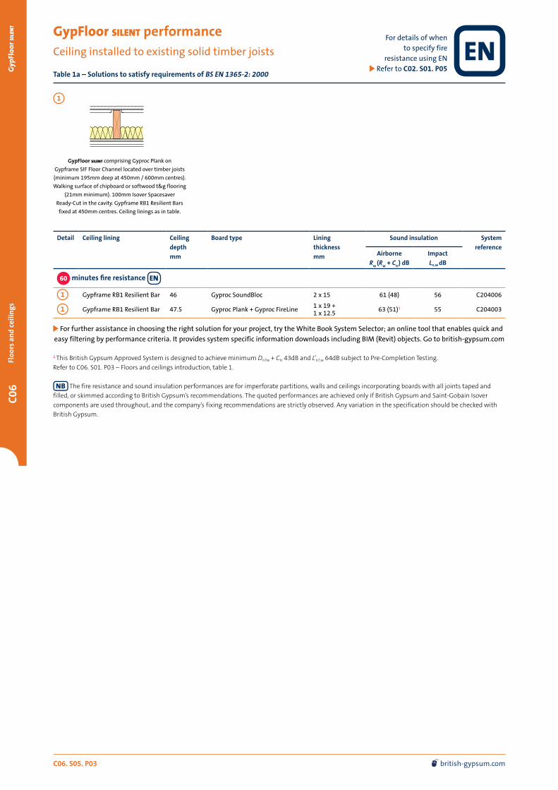
GypFloor silent performanceCeiling installed to existing solid timber joists
Table 1a – Solutions to satisfy requirements of BS EN 1365-2: 2000
Detail Ceiling lining Ceiling
depth
mm
Board type Lining
thickness
mm
Sound insulation System
referenceAirborne
Rw (R
w + C
tr) dB
Impact
Ln,w dB
60 minutes fire resistance
1 Gypframe RB1 Resilient Bar 46 Gyproc SoundBloc 2 x 15 61 (48) 56 C204006
1 Gypframe RB1 Resilient Bar 47.5 Gyproc Plank + Gyproc FireLine1 x 19 + 1 x 12.5
63 (51)1 55 C204003
For further assistance in choosing the right solution for your project, try the White Book System Selector; an online tool that enables quick and
easy filtering by performance criteria. It provides system specific information downloads including BIM (Revit) objects. Go to british-gypsum.com
1 This British Gypsum Approved System is designed to achieve minimum DnTw + Ctr 43dB and L’nT,w 64dB subject to Pre-Completion Testing.
Refer to C06. S01. P03 – Floors and ceilings introduction, table 1.
The fire resistance and sound insulation performances are for imperforate partitions, walls and ceilings incorporating boards with all joints taped and
filled, or skimmed according to British Gypsum’s recommendations. The quoted performances are achieved only if British Gypsum and Saint-Gobain Isover
components are used throughout, and the company’s fixing recommendations are strictly observed. Any variation in the specification should be checked with
British Gypsum.
GypFloor silent comprising Gyproc Plank on
Gypframe SIF Floor Channel located over timber joists
(minimum 195mm deep at 450mm / 600mm centres).
Walking surface of chipboard or softwood t&g flooring
(21mm minimum). 100mm Isover Spacesaver
Ready-Cut in the cavity. Gypframe RB1 Resilient Bars
fixed at 450mm centres. Ceiling linings as in table.
1
For details of when to specify fire
resistance using EN Refer to C02. S01. P05

C06. S05. P04 0115 945 6123 [email protected]
C06G
ypFloor silent
Floors and ceilin
gs
GypFloor silent performance (continued)
Ceiling installed to existing solid timber joists
Table 1b – Solutions to satisfy requirements of BS 476: Part 21: 1987
For further assistance in choosing the right solution for your project, try the White Book System Selector; an online tool that enables quick and
easy filtering by performance criteria. It provides system specific information downloads including BIM (Revit) objects. Go to british-gypsum.com
1 This British Gypsum Approved System is designed to achieve minimum DnTw + Ctr 43dB and L’nT,w 64dB subject to Pre-Completion Testing.
Refer to C06. S01. P03 – Floors and ceilings introduction, table 1.
The fire resistance and sound insulation performances are for imperforate partitions, walls and ceilings incorporating boards with all joints taped and
filled, or skimmed according to British Gypsum’s recommendations. The quoted performances are achieved only if British Gypsum and Saint-Gobain Isover
components are used throughout, and the company’s fixing recommendations are strictly observed. Any variation in the specification should be checked with
British Gypsum.
Detail Ceiling
lining
Ceiling
depth
mm
Board type Lining
thickness
mm
Sound insulation System
referenceAirborne
Rw (R
w + C
tr) dB
Impact
Ln,w dB
60 minutes fire resistance
1 Gypframe RB1 Resilient Bar 46 Gyproc SoundBloc 2 x 15 61 (48) 56 C204006
1 Gypframe RB1 Resilient Bar 47.5 Gyproc Plank + Gyproc SoundBloc1 x 19 + 1 x 12.5
63 (51)1 55 C204001
1 GypLyner universal 91.5 Gyproc Plank + Gyproc SoundBloc1 x 19 + 1 x 12.5
63 (50) 55 C154008
90 minutes fire resistance
1 Gypframe RB1 Resilient Bar 46 Gyproc FireLine 2 x 15 60 (47) 57 C204002
GypFloor silent comprising Gyproc Plank on
Gypframe SIF Floor Channel located over timber joists
(minimum 195mm x 45mm joists at 450mm centres).
Walking surface of chipboard or softwood square edged
flooring (21mm minimum). 100mm Isover Spacesaver
Ready-Cut in the cavity. British Gypsum ceiling installed
to the underside of joists with bars / channels spaced at
450mm centres. Ceiling linings as in table.
1
For details of when to specify fire
resistance using BS Refer to C02. S01. P05

C06. S05. P05 british-gypsum.com
C06
Gyp
Floo
r si
len
tFl
oors
an
d ce
ilin
gs
For details of when to specify fire
resistance using BS Refer to C02. S01. P05
GypFloor silent performance (continued)
Installed to existing solid timber joists (ceiling retained)
Table 2 — Solutions to satisfy requirements of BS 476: Part 21: 1987
1
GypFloor silent comprising Gyproc Plank on
Gypframe SIF Floor Channel located over timber joists.
Walking surface of chipboard or softwood flooring
(21mm minimum t&g). Cavity bridged between joists
(minimum joist width 50mm) by 12.5mm
Glasroc F multiboard resting on 100mm x 12.5mm
Glasroc F multiboard strips (screw-fixed to joists flush
with bottom edge, at 300mm centres).
100mm Isover Spacesaver Ready-Cut in the cavity.
Existing ceiling linings as in table.
For further assistance in choosing the right solution for your project, try the White Book System Selector; an online tool that enables quick and
easy filtering by performance criteria. It provides system specific information downloads including BIM (Revit) objects. Go to british-gypsum.com
1 These systems have an ACTIVair board option available, which improves indoor air quality. Alternatively, all systems can be skim finished
with Thistle PureFinish, which contains ACTIVair technology. Refer to C08. S02. P05 and C02. S01. P49 for further details. 2 Linings used in acoustic tests to simulate a lath and plaster ceiling in good condition.3 The performance was achieved with t&g flooring. For non t&g floors, overlay with 6mm plywood and ensure all joints are staggered.
The fire resistance and sound insulation performances are for imperforate partitions, walls and ceilings incorporating boards with all joints taped and
filled, or skimmed according to British Gypsum’s recommendations. The quoted performances are achieved only if British Gypsum and Saint-Gobain Isover
components are used throughout, and the company’s fixing recommendations are strictly observed. Any variation in the specification should be checked with
British Gypsum.
For non t&g floors, overlay with 6mm plywood and ensure all joints are staggered.
2
GypFloor silent comprising Gyproc Plank on
Gypframe SIF Floor Channel located over timber
joists. Walking surface of chipboard or softwood
flooring (21mm minimum square edge). 100mm
Isover Spacesaver Ready-Cut in the cavity.
Ceiling linings as in table.
Detail Ceiling
lining
Ceiling
depth
mm
ACTIVair
technology
available1
Lining
thickness
mm
Sound insulation System
referenceAirborne
Rw dB
Impact
Ln,w dB
30 minutes fire resistance
2 Gyproc Plank + Gyproc WallBoard 31.5 -1 x 19 + 1 x 12.5
54 63 C204004
2 Existing plasterboard + Gyproc SoundBloc overboarding
25 1 x 12.5 + 1 x 12.5
54 63 C204005
60 minutes fire resistance
1 Gyproc Plank + Gyproc WallBoard2 3 31.5 -1 x 19 + 1 x 12.5
54 63 G104032
2 Existing plasterboard + Gyproc FireLine overboarding
27.5 -1 x 12.5 + 1 x 15
54 63 C204007

C06. S05. P06 0115 945 6123 [email protected]
C06G
ypFloor silent
Floors and ceilin
gs
GypFloor silent design
Building design
GypFloor silent comprises Gypframe SIF Floor Channels positioned
on the upper surface of the timber joists and Gypframe RB1
Resilient Bars fixed to the under side of the timber joists.
Planning – key factors
The GypFloor silent system adds 7mm to the level of the top of the
joists. The finished surface of the applied ceiling linings will be
16mm plus the thickness of the lining boards from the underside
of the joists when Gypframe RB1 Resilient Bar is used. Ceiling
linings should be fixed prior to any installation of drylining or
plastering on walls. If this is not possible, ceiling linings should
neatly abut the wall.
In refurbishment work the level of existing joists should be checked.
Their upper surfaces should be reasonably level and straight for the
flooring application. If there is misalignment of their lower surfaces,
consideration should be given to using a GypLyner universal or
CasoLine mf suspended ceiling to support the ceiling boards.
Structural
The system is primarily intended for timber floors with an intensity
of distributed load of up to 5.0kN/m², and a point load of 4.5kN. An
increase in the mass of the floor will result from upgrading. The load
capacity of the supporting floor joists should therefore be checked,
with due consideration to the effects of lateral buckling and the
need for intermediate restraints. This may be particularly important
where the system is to be used in conjunction with engineered
timber ‘I’ joists.
Flanking transmission
Care should be taken to ensure that the associated structure is
suitable to achieve the level of sound insulation required. Particular
reference to Building Regulations Approved Document E should be
made as regards the use of this floor type and the requirements of
the surrounding structure. Where the walls supporting the floor
weigh less than 365kg/m² the use of an acoustic shield lining to the
walls should be considered. Flanking detail specifications are given
in the current HomeSpec, The White Book Residential Sector Guide,
available to download from british-gypsum.com
Handy hint
Gypframe SIF Floor Channels can accommodate a wide range of joist widths:
— Gypframe SIF1 Floor Channel for joists ≤63mm
— Gypframe SIF4 Floor Channel for joists 64 - 75mm
— Gypframe SIF2 Floor Channel for joists ≥75mm
Ensure that channels are never fixed to the joist.
SpecSure®
All our systems are covered by SpecSure® when using genuine British Gypsum and Saint-Gobain Isover products.
Existing plaster and lath ceilings
In order to ensure the required fire resistance of a floor is achieved,
it is recommended to under-draw the lath and plaster with chicken
wire (fixed in accordance with manufacturer recommendations).
A cavity should then be formed with minimum 38 x 38mm timber
battens or GypLyner universal.
Services
The installation of services within the floor zone should be carried
out to allow easy access from above and should, where possible,
follow the line of the floor joists.
Board finish
Refer to C08. S01. P02 – Finishes.

C06. S05. P07 british-gypsum.com
C06
Gyp
Floo
r si
len
tFl
oors
an
d ce
ilin
gs
GypFloor silent construction details
4
6
7
8
3
3
9
5
9
2
1
1
1
2
Reflected ceiling plan (12.5mm x 1200mm x 2700mm Gyproc SoundBloc over Gyproc Plank fixed to Gypframe RB1 Resilient Bars)
Cut-away floor plan (Chipboard flooring)
1 Solid timber joists
2 Gypframe SIF Floor Channels
3 Gyproc Plank
4 Chipboard flooring
5 Gypframe RB1 Resilient Bar
6 Gyproc SoundBloc
7 Gypframe SIF2 Floor Channel
8 Gypframe RB1 Resilient Bar noggings at room perimeter
9 Isover Spacesaver Ready-Cut

C06. S05. P08 0115 945 6123 [email protected]
C06G
ypFloor silent
Floors and ceilin
gs
GypFloor silent construction details (continued)
9
1
4
2
3
5
6
7
6
7
8
12
7
7
1
2
2
13
10
9
1
1
2
11
4
4
4
5
5
5
6
6
3
4
6
5
Section through floor - joist width over 75mm
Non-loadbearing partition sited over joists
Perimeter junction - inner leaf of external
wall exceeds mass of 365kg/m²
Typical section through floor
11
3
1 Chipboard / softwood flooring
2 Gyproc Plank
3 Gypframe SIF1 / SIF4 Floor Channel
4 Solid timber joist
5 100mm Isover Spacesaver Ready-Cut
6 Gypframe RB1 Resilent Bars1
7 Gyproc plasterboard
8 Wall lining
9 Skirting
10 GypWall partition (low acoustic)
11 Gypframe SIF2 Floor Channel
12 Gypframe RB1 Resilient Bar noggings
13 Fixing length selected to avoid reaching the Gypframe SIF1 Floor Channel
1 Alternatively, a GypLyner universal ceiling system may be specified.

C06. S05. P09 british-gypsum.com
C06
Gyp
Floo
r si
len
tFl
oors
an
d ce
ilin
gs
GypFloor silent system components
Gypframe metal components ( Refer to C10. S02. P02 for details)
Gypframe SIF1 Floor Channel
Channel, with integral acoustic isolator, laid on top
of timber joists less than or equal to 63mm wide to
support Gyproc Plank.
Gypframe SIF2 Floor Channel
Channel, with integral acoustic isolator, laid on
top of timber joists greater than 75mm wide to
support Gyproc Plank. Also used around perimeter.
Gypframe SIF4 Floor Channel
Channel, with integral acoustic isolator, laid on top
of timber joists between 64mm and 75mm wide to
support Gyproc Plank.
Gypframe RB1 Resilient Bar
Acoustically engineered channel to separate board
fixing from the timber joist and to overcome nail
popping. Fixed to underside of joists.
Board products ( Refer to C10. S03. P02 for details)
Gyproc WallBoard1
Standard gypsum plasterboard.Gyproc FireLine1
Gypsum plasterboard with fire resistant additives.
Gyproc Plank
Standard gypsum plasterboard located as an
inner layer and / or located within Gypframe
floor channels.
Glasroc F multiboard
Non-combustible glass-reinforced gypsum board.
Gyproc SoundBloc1
Gypsum plasterboard with a high density core for
enhanced sound insulation performance.
Fixing products ( Refer to C10. S04. P02 for details)
British Gypsum Drywall Screws
Corrosion resistant self-tapping steel screws
for fixing board-to-timber and board-to-metal
framing less than 0.8mm thick.
GypFloor SIF5 Floor Screws
For fixing floorboards through Gyproc Plank into
the Gypframe Floor Channel flange.
British Gypsum Collated Drywall Screws
Corrosion resistant self-tapping steel screws
for fixing board-to-timber and board-to-metal
framing less than 0.8mm thick.
1 Also available in Moisture Resistant (mr) version. mr boards are specified in intermittent wet use areas.

C06. S05. P10 0115 945 6123 [email protected]
C06G
ypFloor silent
Floors and ceilin
gs
Plasterboard accessories ( Refer to C10. S05. P02 for details)
Gyproc Jointing Material
Jointing compounds, ready mixes and adhesives
for reinforcement and finishing of board joints.
Primers and sealers for treatment of boards for
pre-decoration.
Gyproc Drywall PrimerA general purpose plasterboard primer, providing an ideal surface for decoration for most paints and wall coverings.
Gyproc Sealant
Used to seal air paths for optimum sound
insulation.
Gyproc Drywall Sealer
A specially formulated sealer providing vapour
control and a superior finish. Suitable for
decoration with most paints and wall coverings.
Gyproc edge and angle beads
Protecting and enhancing board edges and corners.
Gyproc Joint Tape
A paper tape designed for reinforcement of flat
joints or internal angles.
Finishing products ( Refer to C10. S06. P02 for details)
Thistle MultiFinish
To provide a plaster skim finish on most common
backgrounds including undercoat plasters and
plasterboard.
Thistle PureFinish
To provide a plaster skim finish with
ACTIVair technology. Used to finish most
common backgrounds including undercoat plasters
and plasterboard. For more information refer to
C02. S01. P49.
Thistle BoardFinish
To provide a plaster skim finish to Gyproc
plasterboards.
Plaster accessories
Designed for the reinforcement and finishing of
board joints before plaster skimming.
Thistle ProTape FT50
Self-adhesive 48mm wide glass fibre mesh tape.
Thistle ProTape FT100
Self-adhesive 100mm wide glass fibre mesh tape.
Insulation products ( Refer to C10. S09. P04 for details)
Isover Spacesaver Ready-Cut
Glass mineral wool for enhanced acoustic and
thermal performance.
GypFloor silent system components (continued)

C06. S05. P11 british-gypsum.com
C06
Gyp
Floo
r si
len
tFl
oors
an
d ce
ilin
gs
GypFloor silent installation overview
Additional information
For full installation details, refer to the British Gypsum Site Book, available to download from british-gypsum.com
This is intended to be a basic description of how the system is built.
For detailed installation guidance refer to the British Gypsum Site Book.
Gypframe SIF Floor Channels are located
centrally over the joists. They must not be
fixed to the joists.
Gyproc Plank is cut neatly to fit between
the channels.
100mm Isover Spacesaver Ready-Cut is laid
between joists to rest on the Gypframe RB1
Resilient Bars. The specified ceiling boards
are then screw fixed to the Gypframe RB1
Resilient Bars with the correct length
British Gypsum Drywall Screws to ensure
the screws do not contact the timber joists.
Flooring is laid across the Gypframe SIF
Floor Channels and screw-fixed through the
Gyproc Plank to the channel flange on one
side only, using Gypframe SIF5 Floor Screws.
It is important to ensure that no fixings are
allowed to connect the Gypframe SIF Floor
Channels to the joists.
Gypframe RB1 Resilient Bars are installed
to the underside of the joists with
British Gypsum Drywall Screws.