c1 - the impact of cad on the design process. consider cad drawing, 2d, 3d, rendering and different...
TRANSCRIPT

OPTION C: CAD/CAMC1 - The Impact of CAD on the Design Process
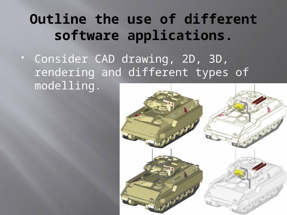
Outline the use of different software applications.
Consider CAD drawing, 2D, 3D, rendering and different types of modelling.
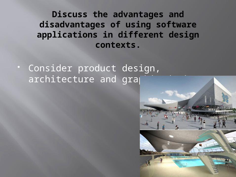
Discuss the advantages anddisadvantages of using softwareapplications in different design
contexts.
Consider product design, architecture and graphic design.

Animation
The ability to link graphic screens together in such a way as to simulate motion or a process.

Virtual Reality.
The ability to simulate a real situation on the screen and interact with it in a near-natural way.
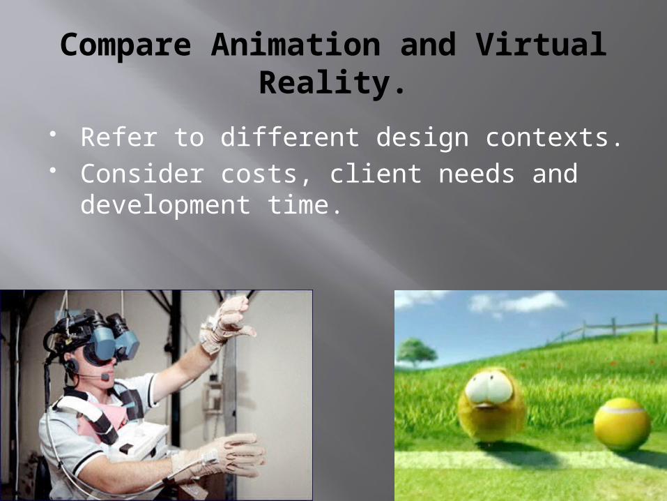
Compare Animation and VirtualReality.
Refer to different design contexts. Consider costs, client needs and
development time.

Discuss the cost-effectiveness offered by animation and virtual reality.
Consider how this helps to reduce full-scale prototyping, which leads to a reduction in tooling costs, labour costs, energy and materials.

Describe Haptic Technology.
Also known as force feedback technology Haptic technology works by using
mechanical actuators to apply forces to the user
By simulating the physics of the user’s virtual world, it is possible to compute these forces into real time.
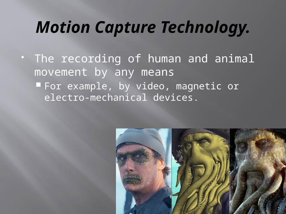
Motion Capture Technology.
The recording of human and animal movement by any means For example, by video, magnetic or electro-
mechanical devices.

Outline how various input devices are used by a CAD system.
Input devices should include… a scanner 3D scanner digital camera graphics tablet

Explain how Haptic Technology and Motion Capture have enhanced design capability.
Haptic technology allows the user to become part of a computer simulation and to interact with it, enabling the designer to observe the user’s performance, so as to design a better outcome.
Haptic technology can also be used in situations where it may prove difficult to train in the real environment.
Haptic technology is also used in feedback devices used in home entertainment consoles.
Capturing a number of users’ movements will allow designers to design better ergonomic products.
Motion capture allows the designer to understand the users’ physiological requirements.
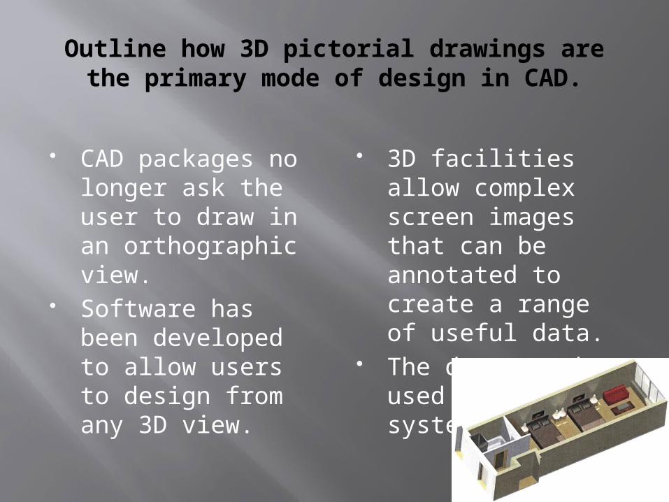
Outline how 3D pictorial drawings are the primary mode of design in CAD.
CAD packages no longer ask the user to draw in an orthographic view.
Software has been developed to allow users to design from any 3D view.
3D facilities allow complex screen images that can be annotated to create a range of useful data.
The data can be used in CAM systems.

Explain how the initial 3D drawings can be used to generate other types of drawing.
For example… Orthographic drawings Presentation virtual product images.
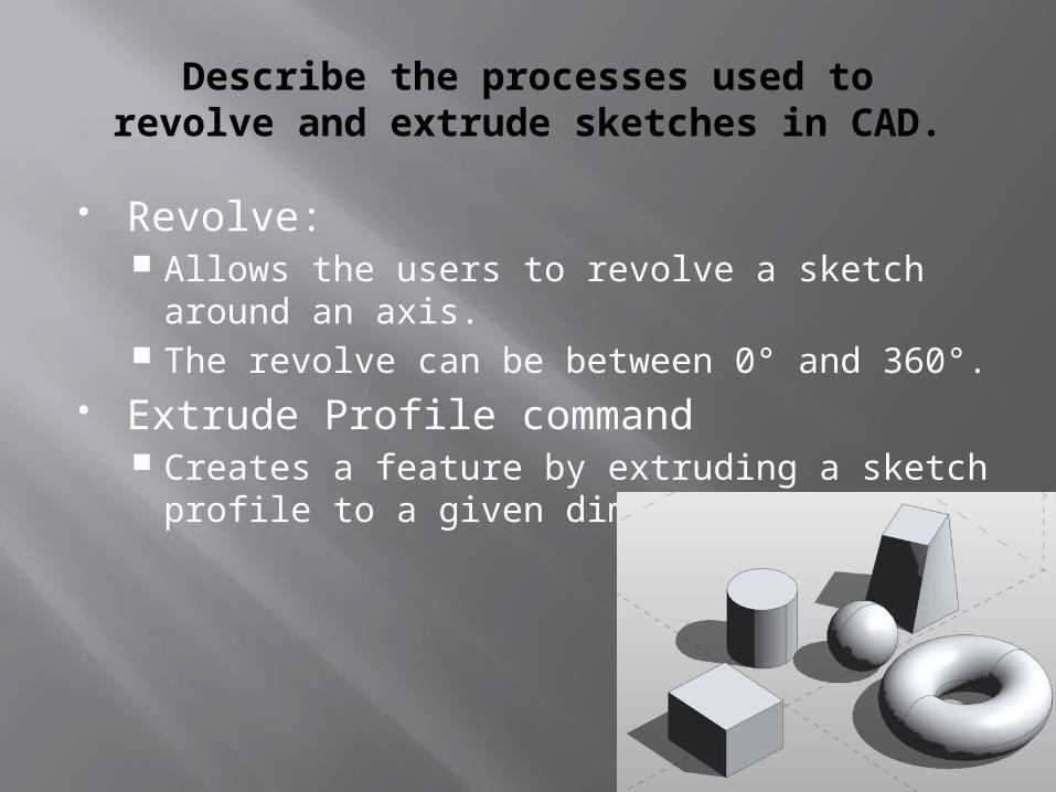
Describe the processes used torevolve and extrude sketches in CAD.
Revolve: Allows the users to revolve a sketch around an
axis. The revolve can be between 0° and 360°.
Extrude Profile command Creates a feature by extruding a sketch profile
to a given dimension.
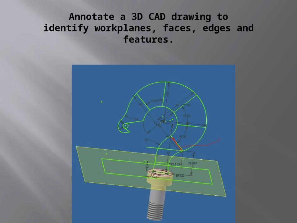
Annotate a 3D CAD drawing toidentify workplanes, faces, edges and
features.

“Top-Down” modelling.
Starts with a 3D shape in which the designer removes material to build the design

“bottom up” modelling.
Starts with an initial sketch in which the designer builds the design.

Compare “bottom up” and “topdown” CAD modelling.
Bottom up: Additive Design Top down: Subtractive Design

Surface Modelling.
A realistic picture of the final model, offering some machining data.
Surface models contain no data about the interior of the part

Solid Modelling.
Solid models are clear representations of the final part.
They provide a complete set of data for the product to be realized.

Explain the differences between solid and surface modelling techniques.
Solid modelling techniques contain more information for the designer in order to produce a 3D model using CNC (computer numerical control) or RP (rapid prototyping) technologies.
Surface modelling has no wall thickness.
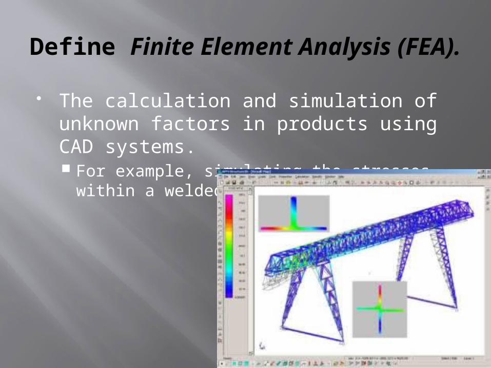
Define Finite Element Analysis (FEA).
The calculation and simulation of unknown factors in products using CAD systems. For example, simulating the stresses within a
welded car part.

Explain how FEA can be used to show the forces acting upon an object while in use.
For example, the maximum load of a vehicle and the stresses acting upon the vehicle from the differences in terrain.

Compare Finite Element Analysis (FEA) with real-life testing.
Consider costs, type of environment, weather and the user when testing vehicles.

Outline how CAD can aid cost analysis in the planning to manufacture.