c30e card printer users guide - alphacard - persona... · 6533 flying cloud drive eden prairie, mn...
TRANSCRIPT
DTC400e/Persona® C30e/M30e Card Printer User Guide (Rev. 1.1)
• Single-side Model • Dual-side Model • Single-side (plus Mag) Model • Dual-side (plus Mag) Model
Part Number: L001364 (user guide)
www.alphacard.com(877) 232-6799
RESTRICTED USE ONLY Fargo Electronics, Inc.
DTC400e/Persona C30e/M30e Card Printer User Guide (Rev. 1.1) 1-2
DTC400e/Persona C30e/M30e Card Printer User Guide (Rev. 1.1), property of Fargo Electronics, Incorporated
Copyright © 2008 by Fargo Electronics, Incorporated. All rights reserved. Printed in the United States of America. Exclusive permission is granted to authorized resellers of Fargo products to reproduce and distribute this copyrighted document to authorized Fargo customers, who have signed a “no disclosure agreement” regarding the restricted, proprietary use of said document.
The revision number for this document will be updated to reflect changes, corrections, updates and enhancements to this document.
Revision Control Number
Date Document Title
Revision 1.1 November 2009 DTC400e/Persona C30e/M30e Card Printer User Guide
Added 64 bit support
Revision 1.0 February 2009 DTC400e/Persona C30e/M30e Card Printer User Guide
These reference documents were thoroughly reviewed to provide Fargo with professional and international standards, requirements, guidelines and models for our technical, training and user documentation. At all times, the Copyright Protection Notice for each document was adhered to within our Fargo documentation process. This reference to other documents does not imply that Fargo is an ISO-certified company at this time.
ANSI/ISO/ASQ Q9001-2000 American National Standard, (sub-title) Quality Management Systems - Requirements (published by the American Society of Quality, Quality Press, P.O. Box 3005, Milwaukee, Wisconsin 53201-3005)
The ASQ ISO 9000:2000 Handbook (editors, Charles A. Cianfrani, Joseph J. Tsiakals and John E. West; Second Edition; published by the American Society of Quality, Quality Press, 600 N. Plankinton Avenue, Milwaukee, Wisconsin 53203)
Juran's Quality Handbook (editors, Joseph M. Juran and A. Blanton Godfrey; Fifth Edition, McGraw-Hill)
Any questions regarding changes, corrections, updates or enhancements to this document should be forwarded to:
Support Services 6533 Flying Cloud Drive Eden Prairie, MN 55344 (USA) (952) 941-0050 FAX: (952) 946-8492 www.fargosupport.com

RESTRICTED USE ONLY Fargo Electronics, Inc.
DTC400e/Persona C30e/M30e Card Printer User Guide (Rev. 1.1) 1-3
Table of Contents Section 1: Introduction _____________________________________________________ 1-1
How to use the manual _______________________________________________________________ 1-1 Safety Messages (review carefully)______________________________________________________ 1-2 DTC400e/C30e/M30e Card Printer Overview _____________________________________________ 1-3
Reviewing the DTC400e/C30e/M30e Block Diagram _____________________________________ 1-3 Reviewing the DTC400e/C30e/M30e Card Printer Sequence of Operations ____________________ 1-4 Reviewing the DTC400e/C30e/M30e Boot up Sequence___________________________________ 1-7
Section 2: Specifications ____________________________________________________ 2-1 Regulatory Compliances ______________________________________________________________ 2-1 Agency Listings_____________________________________________________________________ 2-2 Technical Specifications ______________________________________________________________ 2-2 Functional Specifications _____________________________________________________________ 2-5
Printer Components: Front Cover to USB Port __________________________________________ 2-6 Printer Components: Print Ribbons ___________________________________________________ 2-7 Printer Components: Resin-Only Print Ribbons _________________________________________ 2-8 Printer Components: Dye-Sublimation Print Ribbons_____________________________________ 2-9 Printer Components: Dye-Sublimation/Resin Print Ribbons_______________________________ 2-10 Dye-Sublimation Ribbons for M30e__________________________________________________ 2-10 Printer Components: Blank Cards ___________________________________________________ 2-11
Section 3: Printer Setup & Installation ________________________________________3-1 Choosing A Good Location _________________________________________________________ 3-1 About Moisture Condensation _______________________________________________________ 3-1 Unpacking and Inspection __________________________________________________________ 3-2 Reviewing the Printer (front view) ____________________________________________________ 3-2 Connecting the Printer power ________________________________________________________ 3-3 Flipper Table Module Assembly _____________________________________________________ 3-4 Installing the Print Ribbon Cartridge __________________________________________________ 3-5 Installing Blank Cards into the Card Hopper ____________________________________________ 3-7 Lowering the Card Output Hopper ___________________________________________________ 3-10
Printer Driver Installation ____________________________________________________________ 3-11 Printing a Test Print Image_________________________________________________________ 3-20
Printer Transport ___________________________________________________________________ 3-21 Section 4: General Troubleshooting __________________________________________ 4-1
Safety Messages (review carefully)______________________________________________________ 4-1 Communications Errors_______________________________________________________________ 4-2 Print Process Errors__________________________________________________________________ 4-4
Resolving a Card Not Fed Error (Cards will not feed off the Hopper)_________________________ 4-4 Resolving a Card Not Fed Error (Two (2) or more cards feed at the same time) _________________ 4-7 Resolving a Ribbon RFID Error (Ribbon RFID Antenna is Corrupted)________________________ 4-9 Resolving the Mag Verify Error _____________________________________________________ 4-10 Resolving the No Magnetic Encoder Installed Error _____________________________________ 4-13 Resolving the No Mag Stripe Present Error ____________________________________________ 4-15 Resolving the No Smart Card Encoder Error ___________________________________________ 4-16
Resolving the No Prox Card Encoder Error ______________________________________________ 4-18 Resolving a Ribbon Sensor Error (Ribbon Miscue) DTC400e & C30e _________________________ 4-20
Resolving a Ribbon Break Jam Error _________________________________________________ 4-21 Resolving a Ribbon Out Error ______________________________________________________ 4-24 Resolving a No Ribbon Installed Error________________________________________________ 4-25 Resolving a Invalid Ribbon Error____________________________________________________ 4-26 Resolving a Wrong Ribbon Error ____________________________________________________ 4-28 Resolving a Card Jam Error ________________________________________________________ 4-30

RESTRICTED USE ONLY Fargo Electronics, Inc.
DTC400e/Persona C30e/M30e Card Printer User Guide (Rev. 1.1) 1-4
Resolving a Card Jam (Encoder) Error________________________________________________ 4-32 Resolving a Headlift Motor or Sensor Error____________________________________________ 4-34 Resolving the Cover Open issue_____________________________________________________ 4-36 Resolving the Blank Output issues ___________________________________________________ 4-37 Resolving the Remove Ribbon Message (Rewriteable Job)________________________________ 4-39
Flipper Table Module Assembly Problems _______________________________________________ 4-40 Resolving the No Flipper Table Module problem _______________________________________ 4-40 Resolving the Flipper Jam Error_____________________________________________________ 4-41
Diagnosing Image Problems __________________________________________________________ 4-43 Resolving the Pixel Failure problems_________________________________________________ 4-43 Resolving the Card Surface Debris problems___________________________________________ 4-44 Resolving the Incorrect Image Darkness problems ______________________________________ 4-45 Resolving Ribbon Wrinkle problems _________________________________________________ 4-47 Resolving the Excessive Resin printing problems _______________________________________ 4-49 Resolving the Incomplete Resin printing problems ______________________________________ 4-51 Resolving the Image Placement problems _____________________________________________ 4-52 Resolving the Poor Image Quality problems ___________________________________________ 4-56
Running the Self Test _______________________________________________________________ 4-57 Running the Standard Self Test Print _________________________________________________ 4-58
Section 5: Ethernet Option Introduction _______________________________________5-1 Technical Specification - Ethernet Option ________________________________________________ 5-1 Functional Specification - Ethernet Option________________________________________________ 5-2 Network Services - Overview __________________________________________________________ 5-3
Reviewing the Print Server__________________________________________________________ 5-3 Reviewing the Web Page Server _____________________________________________________ 5-3 Reviewing the Network Management Interface __________________________________________ 5-3 Reviewing the Telnet Server ________________________________________________________ 5-3
Network Management Interface ________________________________________________________ 5-4 Telnet Command Line Interface ________________________________________________________ 5-4
Initiating a Telnet Session __________________________________________________________ 5-4 Reviewing the Telnet Command Table ________________________________________________ 5-5
Ethernet Printer Troubleshooting Procedures ______________________________________5-9 Verifying the Printer Connection ____________________________________________________ 5-10 Verifying the Printer IP address _____________________________________________________ 5-10 Verify that the PC can access the Printer using the ping command __________________________ 5-11 Printing a test page _______________________________________________________________ 5-12
Reviewing Frequently-asked Questions __________________________________________5-13 Glossary of Terms ____________________________________________________________5-17
Section 6: Printer Adjustments_______________________________________________6-1 Safety Messages (review carefully) ___________________________________________________ 6-1
DTC400e/C30e/M30e Print Driver Options _______________________________________________ 6-2 Using the Card tab (DTC400e/C30e/M30e) ________________________________________6-3
Adjusting the Card Size Option ______________________________________________________ 6-3 Adjusting the Orientation Option _____________________________________________________ 6-4 Selecting the number of copies_______________________________________________________ 6-5 Using the Diagnostics button under the Card tab _________________________________________ 6-6 Using the Clean Printer Option_______________________________________________________ 6-7 Using the Test Print button__________________________________________________________ 6-9 Using the About button____________________________________________________________ 6-10 Using the Device Options tab (DTC400e/C30e or M30e) _________________________________ 6-11 Adjusting the Ribbon Type option ___________________________________________________ 6-13 Selecting the Auto Ribbon Select option ______________________________________________ 6-16
RESTRICTED USE ONLY Fargo Electronics, Inc.
DTC400e/Persona C30e/M30e Card Printer User Guide (Rev. 1.1) 1-5
Adjusting the Color Matching option _________________________________________________ 6-20 Adjusting for the Resin Dither ______________________________________________________ 6-21 Using the Print Both Sides option ___________________________________________________ 6-22 Using the Split 1 Set of Ribbon Panels option __________________________________________ 6-23 Using the Print Back Side First option ________________________________________________ 6-24 Using the Print Back Side Only option________________________________________________ 6-25 Using the Rotate Front 180 Degrees or Rotate Back 180 Degrees options ____________________ 6-26 Using the Disable Printing option____________________________________________________ 6-27 Using the Image Color tab (DTC400e/C30e/M30e)______________________________________ 6-28 Using the Resin Heat (K) option (Front and Back) ______________________________________ 6-29 Using the Overlay Heat (O) option___________________________________________________ 6-30 Using the Color Matching option and Default button_____________________________________ 6-31
Using the Calibrate tab (DTC400e/C30e/M30e)____________________________________6-32 Using the Image Position Controls ___________________________________________________ 6-33 Using the Sensors button __________________________________________________________ 6-35 Using the Settings button __________________________________________________________ 6-37
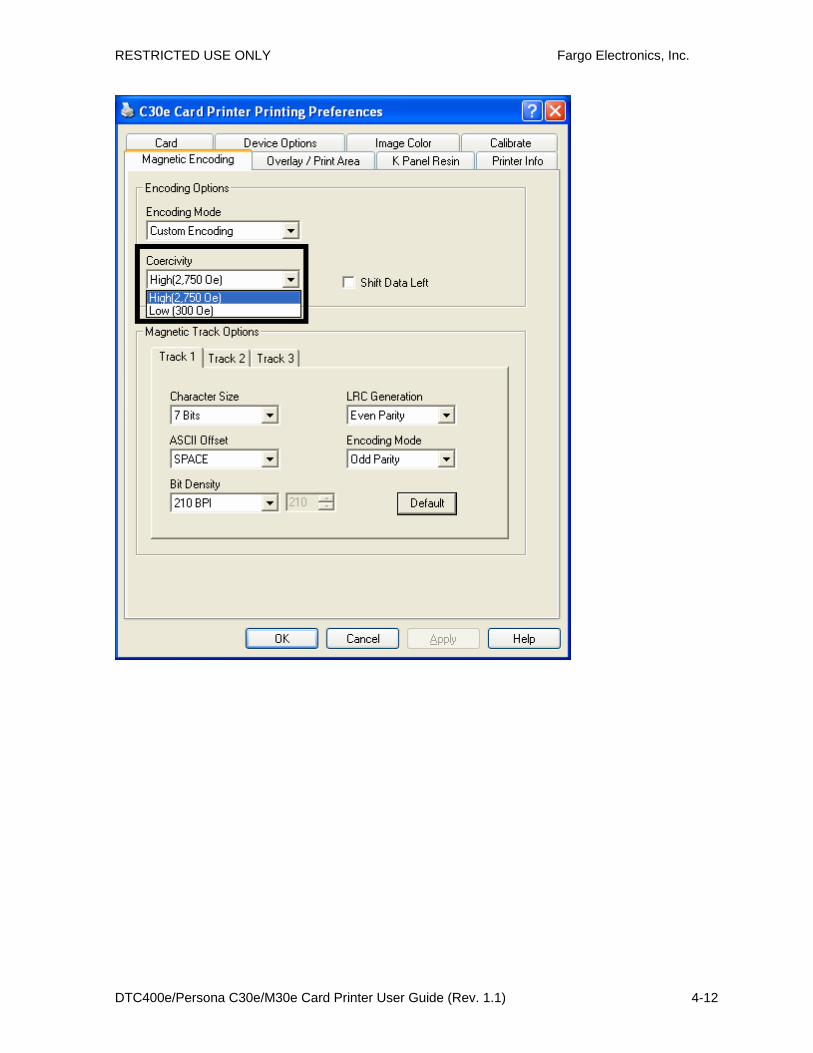
Using the Magnetic Encoding tab _______________________________________________6-38 Using the Encoding Mode dropdown list ______________________________________________ 6-39 Selecting the Coercivity/Magnetic Track ______________________________________________ 6-45 Reviewing the Shift Data Left Function_______________________________________________ 6-46 Reviewing the Magnetic Track Options _______________________________________________ 6-47 Using the Character Size buttons ____________________________________________________ 6-49 Using the ASCII Offset dropdown list ________________________________________________ 6-50 Using the Bit Density dropdown list__________________________________________________ 6-51 Using the LRC Generation dropdown list _____________________________________________ 6-52 Using the Character Parity dropdown list______________________________________________ 6-53 Reviewing the ISO Track Locations__________________________________________________ 6-54 Sending the Track Information______________________________________________________ 6-55 Reviewing the Sample String _______________________________________________________ 6-56 Reviewing the ASCII Code and Character Table ________________________________________ 6-57
Using the Overlay / Print Area tab (DTC400e/C30e/M30e) __________________________6-58 Enabling the Back options _________________________________________________________ 6-59 Using the Front option (Overlay / Print Area) __________________________________________ 6-60 Using the Back option (Overlay / Print Area) __________________________________________ 6-61 Using the Overlay / Print Area dropdown menu ________________________________________ 6-62 Using the Overlay / Print Area ______________________________________________________ 6-64 Using the Defined Area Option _____________________________________________________ 6-66 Using Security Options (Visual Security Solutions) (Front option only) ______________________ 6-70 Selecting Orientation - Landscape under Card tab _______________________________________ 6-71 Selecting the Visual Security Solutions dropdown menu (A to D) __________________________ 6-72 Selecting Orientation - Portrait under Card tab _________________________________________ 6-73 Selecting the Visual Security Solutions dropdown menu (E to H)___________________________ 6-74 Selecting the VeriMark radio button (Frontside option only)_______________________________ 6-75 Selecting HoloMark (Front option only) ______________________________________________ 6-76 Reviewing the Custom VeriMark Card (Custom Graphic in a 2D foil) _______________________ 6-77 Reviewing the Custom HoloMark Card (Custom Graphic in a 2D foil) ______________________ 6-78
Using the K Panel Resin tab (DTC400e/C30e/M30e)________________________________6-79 Enabling the Frontside and Backside options___________________________________________ 6-80 Enabling the Frontside option (K Panel Resin) _________________________________________ 6-81 Enabling the Backside option (K Panel Resin)__________________________________________ 6-82 Selecting from the Print All Black with K Panel options (Front and Back options) _____________ 6-83 Selecting the Full Card option (Front and Back options) __________________________________ 6-84 Selecting the Defined Area(s) option (Front and Back options)_____________________________ 6-85
RESTRICTED USE ONLY Fargo Electronics, Inc.
DTC400e/Persona C30e/M30e Card Printer User Guide (Rev. 1.1) 1-6
Selecting the Undefined Area(s) option (Front and Back options)___________________________ 6-86 Selecting the Defined Area(s) function (Front and Back options) ___________________________ 6-87 Selecting the Print YMC under K and Print K Only options _______________________________ 6-94
Using the Printer Info tab (DTC400e/C30e/M30e)__________________________________6-95 Reviewing the Ribbon Information __________________________________________________ 6-96 Reviewing the Ribbon Level Indicator________________________________________________ 6-96
Using the Printer Calibration Utility (DTC400e/C30e/M30e)_________________________6-97 Using the Image Darkness Option ___________________________________________________ 6-98 Using the Print Top of Form Option__________________________________________________ 6-99 Using the Print End of Form Option_________________________________________________ 6-100 Using the Print Left of Form Option ________________________________________________ 6-101 Using the Magnetic Encoder Voltage Offset Option ____________________________________ 6-102 Adjusting the Hi-Co Voltage Offset _________________________________________________ 6-103 Adjusting the Lo-Co Voltage Offset_________________________________________________ 6-104 Using the Mag Top of Form Option _________________________________________________ 6-105 Using the Ribbon Tension Option __________________________________________________ 6-107 Using the Flipper Home Offset Option_______________________________________________ 6-108 Using the Flipper Center Offset Option ______________________________________________ 6-108 Using the Flipper Smart Angle Offset Option _________________________________________ 6-109 Using the Resin Heat (K) Adjustment (Settings) _______________________________________ 6-110 Using the Print Temperature Offset _________________________________________________ 6-111 Using the Erase Temperature Offset_________________________________________________ 6-112 Using the Flipper Prox Offset Option________________________________________________ 6-113 Using the Flipper Prox Angle Offset Option __________________________________________ 6-114
Section 7: Using the YMCFKO Ribbon in the Workbench_________________________ 7-1 Adding a Secure ID to the Card ______________________________________________________ 7-4 Changing the Secure ID Properties____________________________________________________ 7-5 Adding a Logo to the Card __________________________________________________________ 7-6 Changing the Logo Properties _______________________________________________________ 7-7 Adding a Text on the Card __________________________________________________________ 7-8 Changing the Text Properties ________________________________________________________ 7-9 Fluorescing Panel – Application Specifications _________________________________________ 7-10 Inserting Fluorescent Text _________________________________________________________ 7-10 Insert Fluorescent Image __________________________________________________________ 7-11 Printing Dynamic Text ____________________________________________________________ 7-11
Selecting the NONE- Re-Writable Ribbon Type DTC400e/C30e ______________________7-12 Using the Workbench (to erase the card) ________________________________________________ 7-13 Using the Erase Intensity Option (DTC400e/C30e) ________________________________________ 7-15 Using the Erase Temperature Offset ____________________________________________________ 7-16
Section 8: Cleaning ________________________________________________________8-1 Safety Messages (review carefully)______________________________________________________ 8-1 Supplies (included with the Cleaning Kit) ________________________________________________ 8-2 Cleaning the Printhead _______________________________________________________________ 8-3 Cleaning the Platen and the Card Feed Rollers _____________________________________________ 8-4 Cleaning the Printer’s Interior__________________________________________________________ 8-6 Cleaning the Printer’s Exterior _________________________________________________________ 8-6 Packing the Card Printer ______________________________________________________________ 8-1
Section 9: Firmware Upgrades_______________________________________________ 9-1 Requirements_______________________________________________________________________ 9-1 Safety Messages (review carefully)______________________________________________________ 9-1 Upgrade the Printer Firmware__________________________________________________________ 9-2

RESTRICTED USE ONLY Fargo Electronics, Inc.
DTC400e/Persona C30e/M30e Card Printer User Guide (Rev. 1.1) 1-7
Section 10: Fargo Technical Support ________________________________________ 10-1 Contacting Fargo Technical Support____________________________________________________ 10-1 Reading the Serial Numbers on a Fargo Printer ___________________________________________ 10-2
Finding out when a Fargo Card Printer was manufactured ________________________________ 10-2 Reviewing Example No. 1: Serial Number A9020001 ___________________________________ 10-2
Section 11: Glossary of Terms ______________________________________________ 11-1

Section 1: Introduction How to use the manual The DTC400e/Persona C30e/M30e Card Printer User Guide is designed to provide Installers and Technicians with quick, efficient lookup of related procedures, components and terms. The manual can be used effectively either in soft or hard copy, depending on the preference of the Installer or Technician.
Manual Description
Sequence of Operations, Glossary of Terms and Technical/Functional Specifications (hyper-linked)
You can go directly to the Sequence of Operations, Glossary of Terms, Technical Specifications and Functional Specifications to learn how to use the processes, procedures, functions and windows for the card Printer within concise, correlative tables.
Table of Contents (hyper-linked)
You can use the automated Table of Contents to quickly locate, for example, an error message, a procedure, the index or an appendix.
Troubleshooting, Replacement, Removal, Diagnostic and Navigation Procedures (in hyper-linked Sections)
You can go directly to Specifications, General Troubleshooting, Printer Adjustments, Parts Replacement, Printer Packing, Board Level Diagnostics and Firmware Updates to find troubleshooting, removal and replacement procedures. The section titles are always labeled according to their function for consistent usage.
Cross-Referencing (hyper-linked)
You can use the cross-referencing links to quickly locate, for example, an error message or a procedure.
Comprehensive Index (hyper-linked)
You can use the COMPREHENSIVE INDEX to quickly locate information on the card Printer, relating to a specification, a procedural step, a window or screen, a component, a term, a qualifier or a related feature to this Printer.

RESTRICTED USE ONLY Fargo Electronics, Inc.
DTC400e/Persona C30e/M30e Card Printer User Guide (Rev. 1.1) 1-2
Safety Messages (review carefully)
Symbol Critical Instructions for Safety purposes
Danger:
Failure to follow these installation guidelines can result in death or serious injury. Information that raises potential safety issues is indicated by a warning symbol (as shown to the left).
• To prevent personal injury, refer to the following safety messages before performing an operation preceded by this symbol.
• To prevent personal injury, always remove the power cord prior to performing repair procedures, unless otherwise specified.
• To prevent personal injury, make sure only qualified personnel perform these procedures.
Caution:
This device is electrostatically sensitive. It may be damaged if exposed to static electricity discharges. Information that raises potential electrostatic safety issues is indicated by a warning symbol (as shown to the left).
• To prevent equipment or media damage, refer to the following safety messages before performing an operation preceded by this symbol.
• To prevent equipment or media damage, observe all established Electrostatic Discharge (ESD) procedures while handling cables in or near the Circuit Board and Printhead Assemblies.
• To prevent equipment or media damage, always wear an appropriate personal grounding device (e.g., a high quality wrist strap grounded to avoid potential damage).
• To prevent equipment or media damage, always remove the Ribbon and Cards from the Printer before making any repairs, unless otherwise specified.
• To prevent equipment or media damage, take jewelry off of fingers and hands, as well as thoroughly clean hands to remove oil and debris before working on the Printer.

RESTRICTED USE ONLY Fargo Electronics, Inc.
DTC400e/Persona C30e/M30e Card Printer User Guide (Rev. 1.1) 1-3
DTC400e/C30e/M30e Card Printer Overview Reviewing the DTC400e/C30e/M30e Block Diagram
Motors Sensors Parts 1 Card Feed 6 Card Feed 13 Card Input Roller 2 Print Stepper 7 Ribbon Sensor 14 Cleaning Roller 3 Ribbon Drive 8 Ribbon Encoder 15 Card Feed Roller 4 Print Headlift 9 Headlift Sensor 16 Printhead Cooling
Fan 5 Ribbon Rewind
Motor 10 Printhead Thermistor 17 Card Input Hopper
11 Ribbon LED SNR 18 Magnetic Encoding Head Module
12 RFID Antenna 19 Platen Roller 20 Pinch Roller

RESTRICTED USE ONLY Fargo Electronics, Inc.
DTC400e/Persona C30e/M30e Card Printer User Guide (Rev. 1.1) 1-4
Reviewing the DTC400e/C30e/M30e Card Printer Sequence of Operations
The following sequence describes a full color print job with magnetic encoding.
Step Process
1 The File information is received from the PC.
2 Printer checks the installed Ribbon type (stored in memory) against the Ribbon type command that was sent from the Printer.
• If Ribbon type does not match, the Pause button on the right will begin flashing.
3 The Card Input Motor and Print Stepper Motor engage.
4 The Card Feed Sensor detects leading edge of card and disengages the card input Motor.
Input Hopper
Output Hopper
Cartridge Bay
5 The Card Feed Stepper Motor engages to queue card for magnetic encoding.
6 The Encoding data is written to the card.
7 The Magnetic Encoder verifies while the Stepper reverses the card.
8 The Print Ribbon Drive engages.
RESTRICTED USE ONLY Fargo Electronics, Inc.
DTC400e/Persona C30e/M30e Card Printer User Guide (Rev. 1.1) 1-5
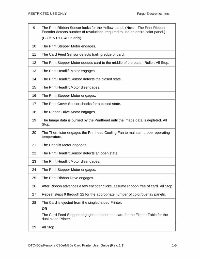
9 The Print Ribbon Sensor looks for the Yellow panel. (Note: The Print Ribbon Encoder detects number of revolutions, required to use an entire color panel.)
(C30e & DTC 400e only)
10 The Print Stepper Motor engages.
11 The Card Feed Sensor detects trailing edge of card.
12 The Print Stepper Motor queues card to the middle of the platen Roller. All Stop.
13 The Print Headlift Motor engages.
14 The Print Headlift Sensor detects the closed state.
15 The Print Headlift Motor disengages.
16 The Print Stepper Motor engages.
17 The Print Cover Sensor checks for a closed state.
18 The Ribbon Drive Motor engages.
19 The Image data is burned by the Printhead until the image data is depleted. All Stop.
20 The Thermistor engages the Printhead Cooling Fan to maintain proper operating temperature.
21 The Headlift Motor engages.
22 The Print Headlift Sensor detects an open state.
23 The Print Headlift Motor disengages.
24 The Print Stepper Motor engages.
25 The Print Ribbon Drive engages.
26 After Ribbon advances a few encoder clicks, assume Ribbon free of card. All Stop.
27 Repeat steps 9 through 22 for the appropriate number of color/overlay panels.
28 The Card is ejected from the singled-sided Printer.
OR The Card Feed Stepper engages to queue the card for the Flipper Table for the dual-sided Printer.
29 All Stop.

RESTRICTED USE ONLY Fargo Electronics, Inc.
DTC400e/Persona C30e/M30e Card Printer User Guide (Rev. 1.1) 1-6
RESTRICTED USE ONLY Fargo Electronics, Inc.
DTC400e/Persona C30e/M30e Card Printer User Guide (Rev. 1.1) 1-7
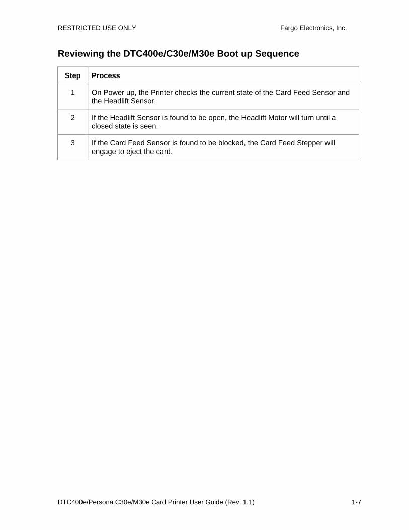
Reviewing the DTC400e/C30e/M30e Boot up Sequence
Step Process
1 On Power up, the Printer checks the current state of the Card Feed Sensor and the Headlift Sensor.
2 If the Headlift Sensor is found to be open, the Headlift Motor will turn until a closed state is seen.
3 If the Card Feed Sensor is found to be blocked, the Card Feed Stepper will engage to eject the card.

RESTRICTED USE ONLY Fargo Electronics, Inc.
DTC400e/Persona C30e/M30e Card Printer User Guide (Rev. 1.1) 2-1
Section 2: Specifications The purpose of this section is to provide the User with specific information on the Regulatory Compliances, Agency Listings, Technical Specifications and Functional Specifications for the DTC400e/Persona C30e/M30e Card Printer User Guide.
Regulatory Compliances
Term Description
CSA
(cUL)
The Printer manufacturer has been authorized by UL to represent the Card Printer as CSA Certified under CSA Standard C22.2 No. 60950-1-03.
File Number: E145118
FCC The Card Printer complies with the requirements in Part 15 of the FCC rules for a Class B digital device. (Note: These requirements are designed to provide reasonable protection against harmful interference in a residential installation.)
If equipment operation in a residential area causes unacceptable interference to radio and TV reception, the operator is required to take whatever steps are necessary to correct the interference.
ITS-EMC The Card Printer has been tested and complies with EN55022 Class B: 1995 and EN82082-1: 1997 standards for EMI emissions.
(Note: Based on the above testing, the Printer manufacturer certifies that the Card Printer complies with all current EMC directives of the European Community and has placed the CE mark on the Card Printer.)
License Number: J99032510
UL The Card Printer is listed under UL IEC 60950-1 (2001) INFORMATION TECHNOLOGY EQUIPMENT.
File Number: E145118

RESTRICTED USE ONLY Fargo Electronics, Inc.
DTC400e/Persona C30e/M30e Card Printer User Guide (Rev. 1.1) 2-2
Agency Listings Term Description
Emissions Standards
CE, FCC, CRC c1374, EN 55022 Class B, FCC Class B, EN 55024: 1998, EN 61000-3-2 and EN 61000-3-3.
Safety Standards UL IEC 60950-1 (2001), CSA C22.2 No. 60950-1-03.
Technical Specifications
Type Description
Accepted Standard Card Sizes
• CR-80 (3.375"L x 2.125"W / 85.6mmL x 54mmW)
• CR-79 (3.295”L x 2.043”W / 83.7mmL x 51.9mmW)
Accepted Card Thickness
9 mil to 40 mil (.009”/.23mm to .040" /1.02mm)
Accepted Card Types
PVC, polyester cards with polished PVC finish.
Re-Writable cards (C30e & DTC 400e only).
Agency Listings
Safety: UL IEC 60950-1 (2001), CSA C22.2 No. 60950-1-03.
Emissions: CE, FCC, CRC c1374, EN 55022 Class B, FCC Class B, EN 55024: 1998, EN 61000-3-2 and EN 61000-3-3.
Card Input Hopper Capacity
100 cards (30 mil)
Colors Up to 16.7 million: Monochrome (M30e monochrome only)
Dimensions See the Size and Weight information in this same table.
Humidity 20-80% non-condensing
Interface USB 20.

RESTRICTED USE ONLY Fargo Electronics, Inc.
DTC400e/Persona C30e/M30e Card Printer User Guide (Rev. 1.1) 2-3
Type Description
ISO Magnetic Encoding
• ISO: This option allows the user to select magnetic encoding that conforms to ISO standard 7811, Parts 1-7.
• ISO Coercivity: ISO magnetic encoding option provides selectable options for either High or Low Coercivity.
See the Using the Magnetic Encoding tab section.
Memory 2MB RAM
Monochrome Printing
The C30e shall render rewriteable card images using a monochrome color pallet.
The M30e shall render card images using a monochrome pallet.
Operating Temperature
65° to 80° F / 18° to 27° C
Print Area CR-80 edge-to-edge
Printer Drivers
32-bit Windows 2000/XP/2003/VISTA ( 32 bit & 64 bit)
Print Method • Dye-Sublimation/Resin Thermal Transfer
• Resin Thermal Transfer
Print Speed Print Speeds**
• 7 seconds per card / 514 cards per hour (K, Color Resin)*
• 12 seconds per card / 300 cards per hour (KO, BO)
• 27 seconds per card / 133 cards per hour (YMCKO)*
• 35 seconds per card / 102 cards per hour (YMCKOK)*
*Indicates the Ribbon type and the number of Ribbon panels printed where Y=Yellow, M=Magenta, C=Cyan, K=Resin Black, O=Overlay,
**Print speed indicates an approximate batch print speed and is measured from the time a card feeds into the printer to the time it ejects from the printer.
Print speeds do not include encoding time or the time needed for the PC to process the image. Process time is dependent on the size of the file, the CPU, amount of RAM and the amount of available resources at the time of the print.
RESTRICTED USE ONLY Fargo Electronics, Inc.
DTC400e/Persona C30e/M30e Card Printer User Guide (Rev. 1.1) 2-4
Type Description
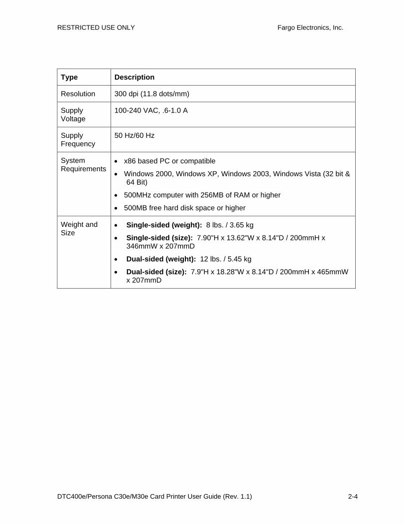
Resolution 300 dpi (11.8 dots/mm)
Supply Voltage
100-240 VAC, .6-1.0 A
Supply Frequency
50 Hz/60 Hz
System Requirements
• x86 based PC or compatible
• Windows 2000, Windows XP, Windows 2003, Windows Vista (32 bit & 64 Bit)
• 500MHz computer with 256MB of RAM or higher
• 500MB free hard disk space or higher
Weight and Size
• Single-sided (weight): 8 lbs. / 3.65 kg
• Single-sided (size): 7.90"H x 13.62"W x 8.14"D / 200mmH x 346mmW x 207mmD
• Dual-sided (weight): 12 lbs. / 5.45 kg
• Dual-sided (size): 7.9"H x 18.28"W x 8.14"D / 200mmH x 465mmW x 207mmD
RESTRICTED USE ONLY Fargo Electronics, Inc.
DTC400e/Persona C30e/M30e Card Printer User Guide (Rev. 1.1) 2-5
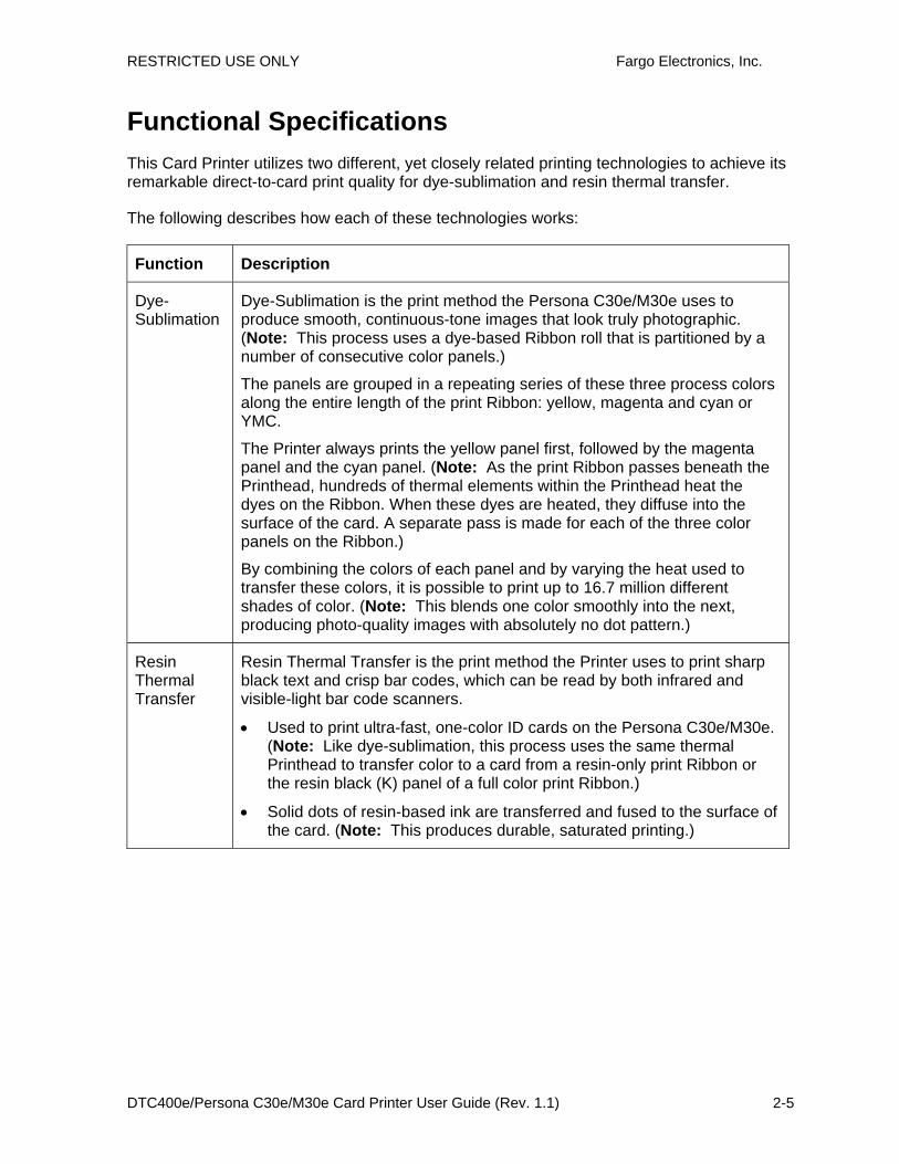
Functional Specifications This Card Printer utilizes two different, yet closely related printing technologies to achieve its remarkable direct-to-card print quality for dye-sublimation and resin thermal transfer.
The following describes how each of these technologies works:
Function Description
Dye-Sublimation
Dye-Sublimation is the print method the Persona C30e/M30e uses to produce smooth, continuous-tone images that look truly photographic. (Note: This process uses a dye-based Ribbon roll that is partitioned by a number of consecutive color panels.)
The panels are grouped in a repeating series of these three process colors along the entire length of the print Ribbon: yellow, magenta and cyan or YMC.
The Printer always prints the yellow panel first, followed by the magenta panel and the cyan panel. (Note: As the print Ribbon passes beneath the Printhead, hundreds of thermal elements within the Printhead heat the dyes on the Ribbon. When these dyes are heated, they diffuse into the surface of the card. A separate pass is made for each of the three color panels on the Ribbon.)
By combining the colors of each panel and by varying the heat used to transfer these colors, it is possible to print up to 16.7 million different shades of color. (Note: This blends one color smoothly into the next, producing photo-quality images with absolutely no dot pattern.)
Resin Thermal Transfer
Resin Thermal Transfer is the print method the Printer uses to print sharp black text and crisp bar codes, which can be read by both infrared and visible-light bar code scanners.
• Used to print ultra-fast, one-color ID cards on the Persona C30e/M30e. (Note: Like dye-sublimation, this process uses the same thermal Printhead to transfer color to a card from a resin-only print Ribbon or the resin black (K) panel of a full color print Ribbon.)
• Solid dots of resin-based ink are transferred and fused to the surface of the card. (Note: This produces durable, saturated printing.)
RESTRICTED USE ONLY Fargo Electronics, Inc.
DTC400e/Persona C30e/M30e Card Printer User Guide (Rev. 1.1) 2-6
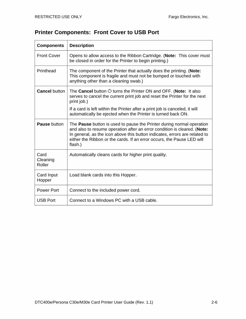
Printer Components: Front Cover to USB Port
Components Description
Front Cover Opens to allow access to the Ribbon Cartridge. (Note: This cover must be closed in order for the Printer to begin printing.)
Printhead The component of the Printer that actually does the printing. (Note: This component is fragile and must not be bumped or touched with anything other than a cleaning swab.)
Cancel button The Cancel button turns the Printer ON and OFF. (Note: It also serves to cancel the current print job and reset the Printer for the next print job.)
If a card is left within the Printer after a print job is canceled, it will automatically be ejected when the Printer is turned back ON.
Pause button The Pause button is used to pause the Printer during normal operation and also to resume operation after an error condition is cleared. (Note: In general, as the icon above this button indicates, errors are related to either the Ribbon or the cards. If an error occurs, the Pause LED will flash.)
Card Cleaning Roller
Automatically cleans cards for higher print quality.
Card Input Hopper
Load blank cards into this Hopper.
Power Port Connect to the included power cord.
USB Port Connect to a Windows PC with a USB cable.

RESTRICTED USE ONLY Fargo Electronics, Inc.
DTC400e/Persona C30e/M30e Card Printer User Guide (Rev. 1.1) 2-7
Printer Components: Print Ribbons
The Card Printer utilizes both dye-sublimation and/or resin thermal transfer methods to print images directly onto blank cards. Since the dye-sublimation and the resin thermal transfer print methods each provide their own unique benefits, print Ribbons are available in resin-only, dye-sublimation-only and combination dye-sublimation/resin versions.
To make it easier to remember which print Ribbons are which, a letter code has been developed to indicate the type of Ribbon panels found on each Ribbon. This letter code is as follows:
C30e & DTC400e
= Dye-Sublimation Yellow Panel
= Dye-Sublimation Magenta Panel
= Dye-Sublimation Cyan Panel
= Resin Black Panel
= Clear Protective Overlay Panel
= Ultra Violet Fluorescing Panel DTC 400e
M30e
B = Dye-Sub Black Panel
= Resin Black Panel
= Clear Protective Overlay Panel

RESTRICTED USE ONLY Fargo Electronics, Inc.
DTC400e/Persona C30e/M30e Card Printer User Guide (Rev. 1.1) 2-8
Printer Components: Resin-Only Print Ribbons
Resin-only print Ribbons consist of a continuous roll of a single resin color. No protective overlay panel (O) is provided since resin images do not require the protection of such an overlay. The following resin-only Ribbon types are available for use with the DTDC400e/Persona C30e/M30e.
Type Description
Standard Resin Black (K) (provides 1,000 prints)
This Ribbon provides high resin durability ideal for most general-purpose monochrome ID card applications. Resin black bar codes are readable by both infrared and visible-light bar codes scanners.
Premium Resin Black (K) (provides 1,000 prints)
This Ribbon provides maximum resin durability ideal for applications such as access control where cards are repeatedly swiped through a Magnetic Stripe reader. Resin black bar codes are readable by both infrared and visible-light bar codes scanners.
(Note: Using a Premium Resin Black Ribbon will provide better photo realistic output.)
Colored Resin
(provides 1,000 prints)
Several colored resin Ribbons are available in a variety of colors for customizing or color-coding resin-only ID cards.
Metallic Resin
(provides 500 prints)
Metallic resin Ribbons are available for printing resin images with a unique metallic sheen.
RESTRICTED USE ONLY Fargo Electronics, Inc.
DTC400e/Persona C30e/M30e Card Printer User Guide (Rev. 1.1) 2-9
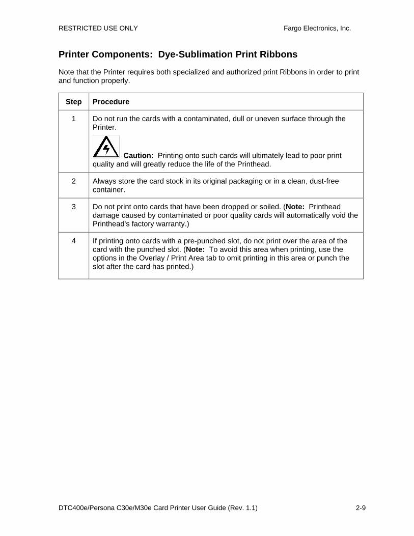
Printer Components: Dye-Sublimation Print Ribbons
Note that the Printer requires both specialized and authorized print Ribbons in order to print and function properly.
Step Procedure
1 Do not run the cards with a contaminated, dull or uneven surface through the Printer.
Caution: Printing onto such cards will ultimately lead to poor print quality and will greatly reduce the life of the Printhead.
2 Always store the card stock in its original packaging or in a clean, dust-free container.
3 Do not print onto cards that have been dropped or soiled. (Note: Printhead damage caused by contaminated or poor quality cards will automatically void the Printhead's factory warranty.)
4 If printing onto cards with a pre-punched slot, do not print over the area of the card with the punched slot. (Note: To avoid this area when printing, use the options in the Overlay / Print Area tab to omit printing in this area or punch the slot after the card has printed.)

RESTRICTED USE ONLY Fargo Electronics, Inc.
DTC400e/Persona C30e/M30e Card Printer User Guide (Rev. 1.1) 2-10
Printer Components: Dye-Sublimation/Resin Print Ribbons
Type Description
Dye-Sublimation/ resin print Ribbon
The Dye-Sublimation/resin print Ribbon combines the yellow (Y), magenta (M) and cyan (C) dye-sublimation panels with a resin black (K) panel.
By combining both types of Ribbon panels, this Ribbon can be used to print full-color, photo-quality images with the dye-sublimation panels along with sharp, black text and bar codes with the resin black panel.
A clear overlay panel (O) is also included on most Ribbons to protect the dye-sublimation images. Dye-Sublimation images must have an overlay panel applied to them or they will quickly begin to wear or fade.
Full-Color (YMCKO) (provides 250 prints)
This Ribbon is used to print full-color photo ID cards along with resin black text and bar codes. Both infrared and visible-light bar code scanners can read bar codes printed with resin black.
• An overlay panel (O) is included to protect the full-color dye-sublimation printing.
YMCKOK The designation of colored Ribbon by the Panels of color in the order in which they are printed: Yellow (Y), Magenta (M), Cyan (C), Black (K), Overlay (O), Black (K) (used for backside, black only printing).
YMCFKO Here are the colored Ribbon designations. The Panels of color are displayed in the order in which they are printed: Yellow (Y), Magenta (M), Cyan (C), Flourescent (F), Black (K), Overlay (O).
YMCFKOK Here are the colored Ribbon designations. The Panels of color are displayed in the order in which they are printed: Yellow (Y), Magenta (M), Cyan (C), Flourescent (F), Black (K), Overlay (O) and Black (K) (used for backside, black only printing.)
Dye-Sublimation Ribbons for M30e
Type Description
BO The BO print Ribbon uses the Black (B) dye-sublimation panel

RESTRICTED USE ONLY Fargo Electronics, Inc.
DTC400e/Persona C30e/M30e Card Printer User Guide (Rev. 1.1) 2-11
A clear overlay panel (O) is also included Ribbons to protect the dye-sublimation images. Dye-Sublimation images must have an overlay panel applied to them or they will quickly begin to wear or fade.
Printer Components: Blank Cards
Type Description
Card Size The Card Printer accepts standard CR-80 and CR-79 sized cards.
Card Design
The Printer will print onto any card with a clean, level and polished PVC surface.
Although the Printer is equipped with card cleaning Rollers, it is very important to always print onto cards specifically designed for direct-to-card dye-sublimation printing.
Card Surface
Suitable cards must have a polished PVC surface free of fingerprints, dust or any other types of embedded contaminants. In addition, cards must have a completely smooth, level surface in order for the Printer to achieve consistent color coverage.
Certain types of Proximity cards have an uneven surface that will inhibit consistent color transfer.
• Certain types of smart card chips are raised slightly above the cards surface which also results in poor color transfer.
UltraCard Stock
Due to the importance of using high-quality blank cards, a factory-approved card stock called UltraCard™ is available and recommended for best results.
• UltraCard stock has a glossy PVC laminate on top and bottom and is optically inspected to provide the cleanest, most scratch and debris-reduced cards possible.
• Two types of these cards are available: UltraCard and UltraCard III. UltraCard stock has a PVC core and offers medium card durability. UltraCard III stock has a 40% polyester core and offers high durability.
• Both types of UltraCards produce printed images with a glossy, photo-quality finish.
The following guide will walk you through the installation of the Persona C30e/M30e Card Printer Driver.
• Time Requirement (software): This software installation process will require approximately 2 to 5 minutes (depending on the speed of your PC).
• Time Requirement (Printer): The time required to set up a standard Persona C30e/M30e Printer would be approximately 5 to 10 minutes.

RESTRICTED USE ONLY Fargo Electronics, Inc.
DTC400e/Persona C30e/M30e Card Printer User Guide (Rev. 1.1) 2-12
The System Requirements are as follows:
• x86 PC or compatible, Windows 2000, Windows XP, Windows 2003, 500MHz computer with 256MB of RAM or higher, 500MB free hard disk space or higher
• Printer Setup and Installation

RESTRICTED USE ONLY Fargo Electronics, Inc.
DTC400e/Persona C30e/M30e Card Printer User Guide (Rev. 1.1) 3-1
Section 3: Printer Setup & Installation Choosing A Good Location
Follow these guidelines:
• Place the unit in a location with adequate air circulation to prevent internal heat build up.
• Use the Printer's dimensions as a guideline for the minimum clearances to the unit. (Note: Allow for adequate clearance in front of the unit to accommodate the unit with its Covers open.)
• Do not install unit near heat sources such as radiators or air ducts or in a place subject to direct sunlight, excessive dust, mechanical vibration or shock.
About Moisture Condensation
If the unit is brought directly from a cold to a warm location or is placed in a very damp room, moisture may condense inside the unit. Should this occur, print quality may not be optimum.
Leave the unit turned OFF in a warm, dry room for several hours before using. This will allow the moisture to evaporate.

RESTRICTED USE ONLY Fargo Electronics, Inc.
DTC400e/Persona C30e/M30e Card Printer User Guide (Rev. 1.1) 3-2
Unpacking and Inspection
While unpacking your Printer, inspect the carton to ensure that no damage has occurred during shipping. Make sure that all supplied accessories are included with your unit.
Check that the following items are included:
• Power Supply
• US / EU Power Cable
• Software Installation CD/User Guide
• User Guide
• Warranty Statement, Registration Card and Compliancy Document
Reviewing the Printer (front view)
Input Hopper
Output Hopper
Cartridge Bay

RESTRICTED USE ONLY Fargo Electronics, Inc.
DTC400e/Persona C30e/M30e Card Printer User Guide (Rev. 1.1) 3-3
Reviewing the Printer (front view; Cartridge being installed)
Connecting the Printer power
Follow this procedure. (Note: Do not connect the Printer’s USB cable until prompted during the Printer Driver installation.)
Step Procedure
1 Plug the AC adapter power cable into the back of the Printer. See Display A.
2 Plug the wall power cable into the AC power adapter.
3 Plug the wall power cable into a standard 110VAC power outlet.
Display A – Shows back of Printer with AC power cable (below).

RESTRICTED USE ONLY Fargo Electronics, Inc.
DTC400e/Persona C30e/M30e Card Printer User Guide (Rev. 1.1) 3-4
Flipper Table Module Assembly
The Flipper Table Module Assembly (D900200) is an automated Flipping Module that allows the Printer to print on the frontside and backside of each card.
Display: Flipper Table Module Assembly

RESTRICTED USE ONLY Fargo Electronics, Inc.
DTC400e/Persona C30e/M30e Card Printer User Guide (Rev. 1.1) 3-5
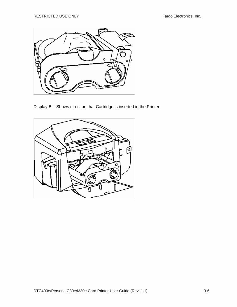
Installing the Print Ribbon Cartridge
The DTC400e/C30e/M30e Card Printer uses a one-piece, disposable Ribbon Cartridge load system.
Step Procedure
1 To install the Ribbon Cartridge, simply open the front Cover by pressing the black rubber pad or touch pad and lowering the Cover down, as shown below.
2 a. Remove the liner on the Card Cleaning Roller before installing the Cartridge, as shown in Display A (upper right arrow of display).
b. Remove the Ribbon securing tape, as shown in Display A (middle right arrow of display).
3 Slide the Ribbon Cartridge into the Printer, as shown in this section.
4 Raise the front Cover and press the front Cover’s black rubber pad or touch pad to secure it.
Display A – Shows the Print Ribbon Cartridge before it is installed or inserted into the Printer. The Card Cleaning Roller (see arrow) is already inserted into the Print Ribbon Cartridge.
RESTRICTED USE ONLY Fargo Electronics, Inc.
DTC400e/Persona C30e/M30e Card Printer User Guide (Rev. 1.1) 3-6
Display B – Shows direction that Cartridge is inserted in the Printer.

RESTRICTED USE ONLY Fargo Electronics, Inc.
DTC400e/Persona C30e/M30e Card Printer User Guide (Rev. 1.1) 3-7
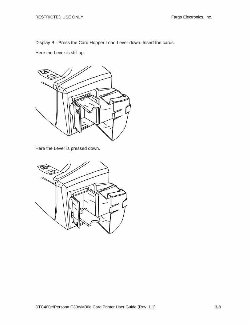
Installing Blank Cards into the Card Hopper
The DTC400e/C30e/M30e Printer is capable of printing single load cards and multiple feed cards (batch mode).
• To print using single feed, simply remove all cards from the Card Hopper, leave the Card Hopper door closed and place a card in the single Feed Card Slot (which can be used repeatedly).
• Again, the cards should be loaded with the print side down and (if applicable) the magnetic strip up and towards the front of the Printer.
To print using Batch Mode follow the instructions below.
Step Procedure
1 Open the Card Hopper Cover.
2 Press the Card Hopper Load Lever down until the Card Tray locks into place, as shown in Display B in this section.
3 Load up to 100 cards into the Hopper with the print side down.
If using cards with a magnetic stripe, the magnetic stripe should be loaded with the stripe up and to the front of the Printer, as shown in Display C in this section.
4 Close the Card Hopper Cover to release the Card Tray.
Display A – This is a graphics showing how to insert the cards.
RESTRICTED USE ONLY Fargo Electronics, Inc.
DTC400e/Persona C30e/M30e Card Printer User Guide (Rev. 1.1) 3-8
Display B - Press the Card Hopper Load Lever down. Insert the cards.
Here the Lever is still up.
Here the Lever is pressed down.
RESTRICTED USE ONLY Fargo Electronics, Inc.
DTC400e/Persona C30e/M30e Card Printer User Guide (Rev. 1.1) 3-9
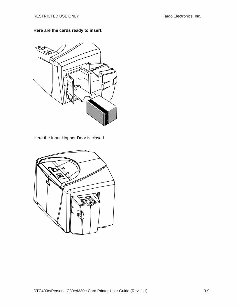
Here are the cards ready to insert.
Here the Input Hopper Door is closed.
RESTRICTED USE ONLY Fargo Electronics, Inc.
DTC400e/Persona C30e/M30e Card Printer User Guide (Rev. 1.1) 3-10
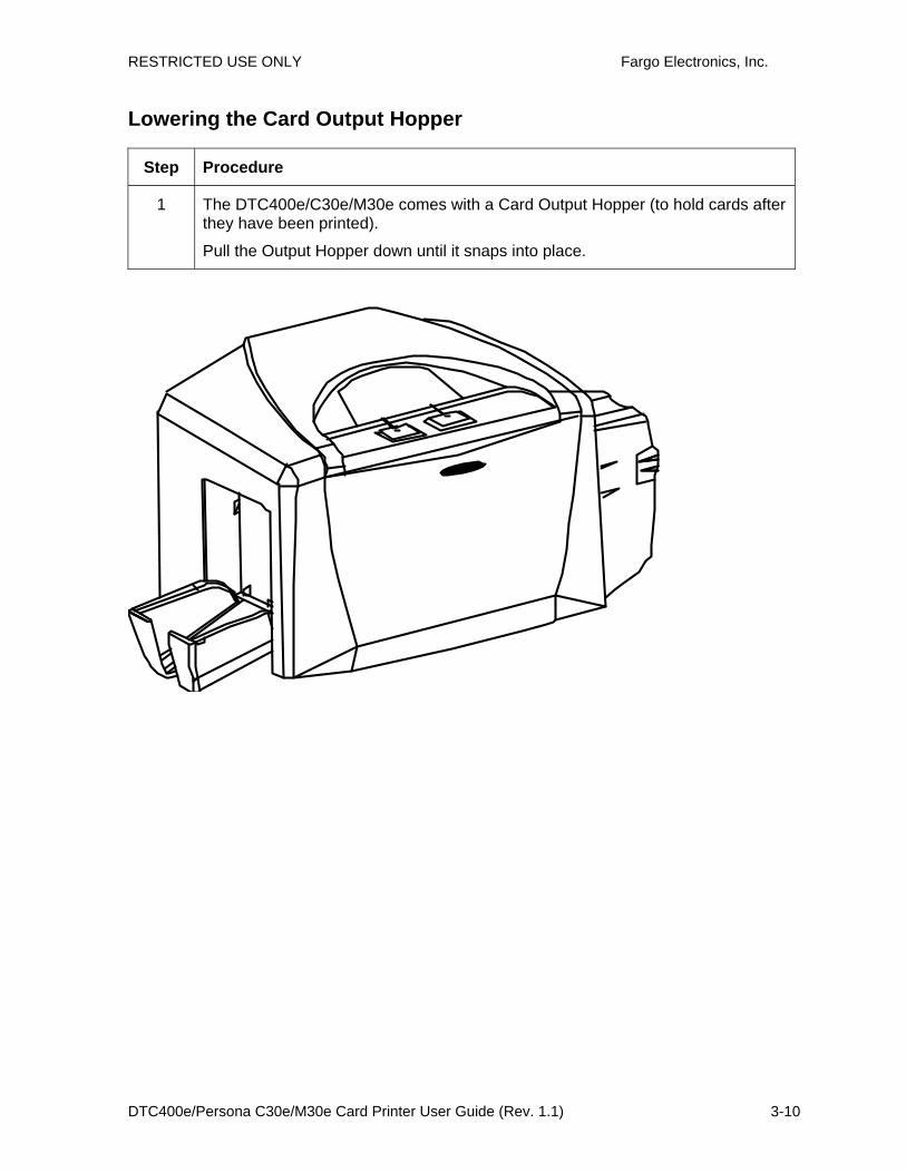
Lowering the Card Output Hopper
Step Procedure
1 The DTC400e/C30e/M30e comes with a Card Output Hopper (to hold cards after they have been printed).
Pull the Output Hopper down until it snaps into place.
RESTRICTED USE ONLY Fargo Electronics, Inc.
DTC400e/Persona C30e/M30e Card Printer User Guide (Rev. 1.1) 3-11
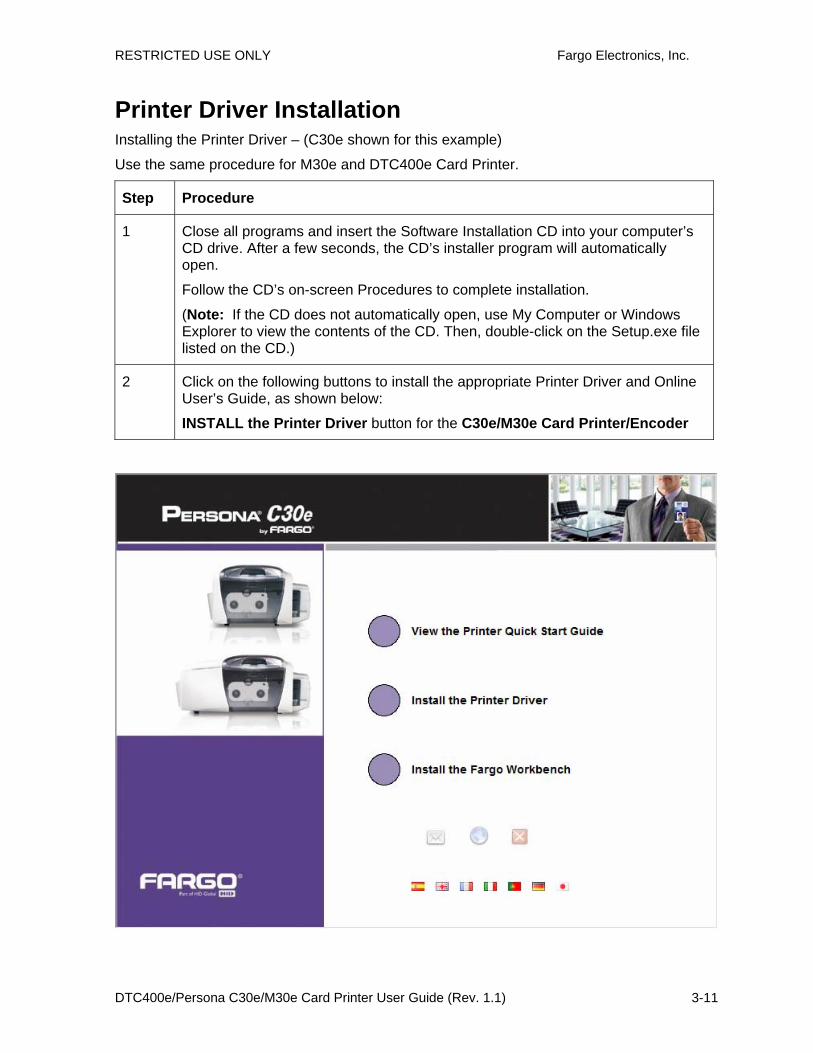
Printer Driver Installation Installing the Printer Driver – (C30e shown for this example)
Use the same procedure for M30e and DTC400e Card Printer.
Step Procedure
1 Close all programs and insert the Software Installation CD into your computer’s CD drive. After a few seconds, the CD’s installer program will automatically open.
Follow the CD’s on-screen Procedures to complete installation.
(Note: If the CD does not automatically open, use My Computer or Windows Explorer to view the contents of the CD. Then, double-click on the Setup.exe file listed on the CD.)
2 Click on the following buttons to install the appropriate Printer Driver and Online User’s Guide, as shown below:
INSTALL the Printer Driver button for the C30e/M30e Card Printer/Encoder

RESTRICTED USE ONLY Fargo Electronics, Inc.
DTC400e/Persona C30e/M30e Card Printer User Guide (Rev. 1.1) 3-12
3 Click on the Next button to continue with the Setup program.
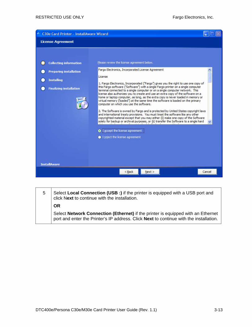
4 Read the License Agreement. Select the I accept the license agreement option and click Next to continue.
RESTRICTED USE ONLY Fargo Electronics, Inc.
DTC400e/Persona C30e/M30e Card Printer User Guide (Rev. 1.1) 3-13
5 Select Local Connection (USB :) if the printer is equipped with a USB port and click Next to continue with the installation.
OR Select Network Connection (Ethernet) if the printer is equipped with an Ethernet port and enter the Printer’s IP address. Click Next to continue with the installation.

RESTRICTED USE ONLY Fargo Electronics, Inc.
DTC400e/Persona C30e/M30e Card Printer User Guide (Rev. 1.1) 3-14
6 Click Next to begin the installation.
RESTRICTED USE ONLY Fargo Electronics, Inc.
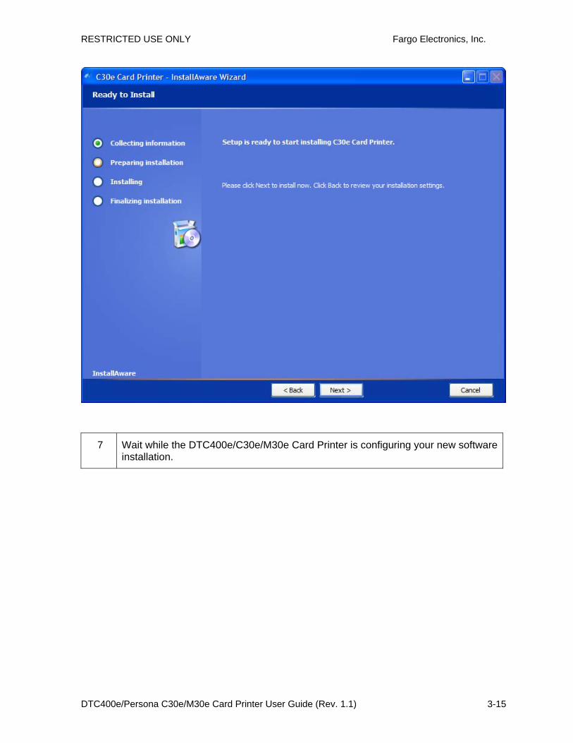
DTC400e/Persona C30e/M30e Card Printer User Guide (Rev. 1.1) 3-15
7 Wait while the DTC400e/C30e/M30e Card Printer is configuring your new software installation.

RESTRICTED USE ONLY Fargo Electronics, Inc.
DTC400e/Persona C30e/M30e Card Printer User Guide (Rev. 1.1) 3-16
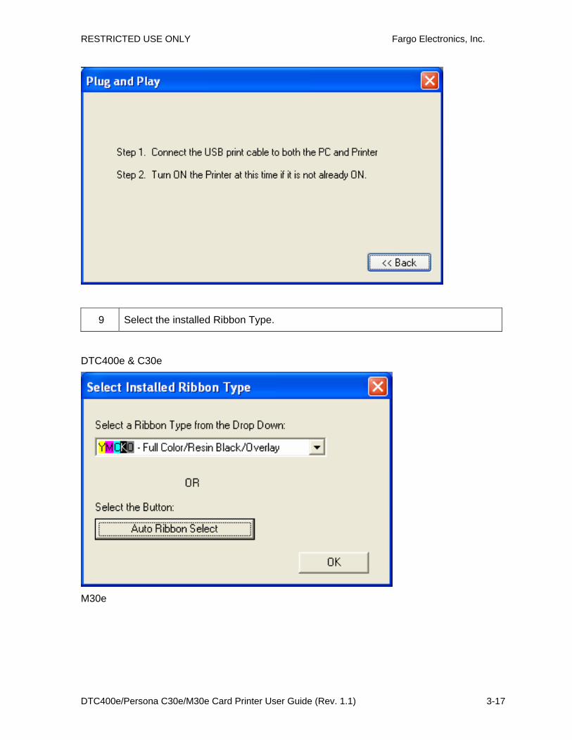
8 This step only applies to local connection installation (USB).
a. Connect the USB cable to the Printer.
b. Turn ON the Printer at this time if it is not already ON.
c. Wait during the installation.
RESTRICTED USE ONLY Fargo Electronics, Inc.
DTC400e/Persona C30e/M30e Card Printer User Guide (Rev. 1.1) 3-17
9 Select the installed Ribbon Type.
DTC400e & C30e
M30e
RESTRICTED USE ONLY Fargo Electronics, Inc.
DTC400e/Persona C30e/M30e Card Printer User Guide (Rev. 1.1) 3-18
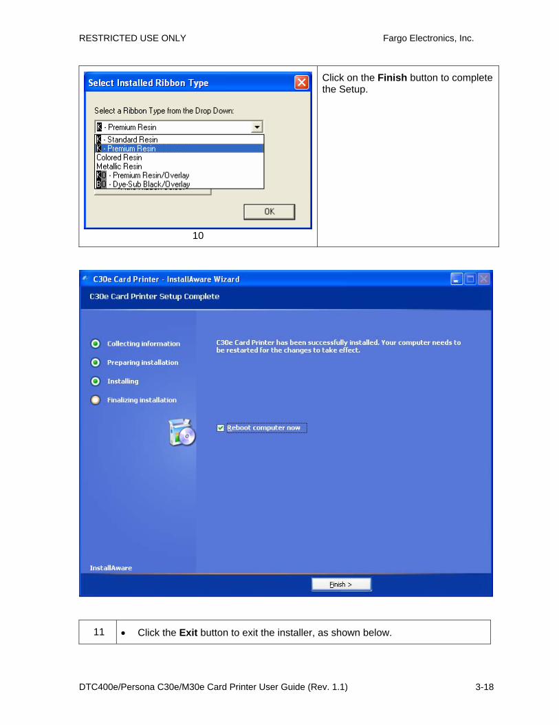
10
Click on the Finish button to complete the Setup.
11 • Click the Exit button to exit the installer, as shown below.

RESTRICTED USE ONLY Fargo Electronics, Inc.
DTC400e/Persona C30e/M30e Card Printer User Guide (Rev. 1.1) 3-19
OR
• Click on Install the Fargo Workbench.
12 You have completed the installation

RESTRICTED USE ONLY Fargo Electronics, Inc.
DTC400e/Persona C30e/M30e Card Printer User Guide (Rev. 1.1) 3-20
Printing a Test Print Image
Step Procedure
1 a. From your computer’s startup menu, select Settings > Printers and Faxes (Windows XP, 2003) or > Printers (Windows 2000).
b. Double click on the DTC400e or Persona C30e or M30e Card Printer under the Printers window.
c. Select Printing Preferences under the Printer drop-down menu. This will bring up the Printing Preferences window.
2 a. Select the Card tab, and then click on the Test Print button, as shown in Display A in this section. (Important: Ensure that the Ribbon is installed before proceeding. The correct Ribbon type is selected in the Device Options tab.)
b. When the Test Print button is selected, an image is copied to the Printer.
Display A - Persona C30e/M30e Printer Driver Card tab

RESTRICTED USE ONLY Fargo Electronics, Inc.
DTC400e/Persona C30e/M30e Card Printer User Guide (Rev. 1.1) 3-21
Printer Transport Moving the Printer to another location
Step Procedure
1 The Printer can be transported by gripping it under the back lid, as shown in the photo below.
2 You have completed the setup and installation procedures in this section.

RESTRICTED USE ONLY Fargo Electronics, Inc.
DTC400e/Persona C30e/M30e Card Printer User Guide (Rev. 1.1) 4-1
Section 4: General Troubleshooting This section provides Troubleshooting procedures for this Printer for Communication Errors, Card Feed Errors, Print Process Errors, Card Jam Errors, Encoding Errors and Diagnosing Image Problems.
NOTE: ANY PART REPLACEMENT REFERENCES MUST BE DONE BY FARGO AUTHORIZED DEALERS OR FARGO REPAIR DEPARTMENT ONLY.
Safety Messages (review carefully) Symbol Critical Instructions for Safety purposes
Danger:
Failure to follow these installation guidelines can result in death or serious injury. Information that raises potential safety issues is indicated by a warning symbol (as shown to the left).
• To prevent personal injury, refer to the following safety messages before performing an operation preceded by this symbol.
• To prevent personal injury, always remove the power cord prior to performing repair procedures, unless otherwise specified.
• To prevent personal injury, make sure only qualified personnel perform these procedures.
Caution:
This device is electrostatically sensitive. It may be damaged if exposed to static electricity discharges. Information that raises potential electrostatic safety issues is indicated by a warning symbol (as shown to the left).
• To prevent equipment or media damage, refer to the following safety messages before performing an operation preceded by this symbol.
• To prevent equipment or media damage, observe all established Electrostatic Discharge (ESD) procedures while handling cables in or near the Circuit Board and Printhead Assemblies.
• To prevent equipment or media damage, always wear an appropriate personal grounding device (e.g., a high quality wrist strap grounded to avoid potential damage).
• To prevent equipment or media damage, always remove the Ribbon and Cards from the Printer before making any repairs, unless otherwise specified.
• To prevent equipment or media damage, take jewelry off of fingers and hands, as well as thoroughly clean hands to remove oil and debris before working on the Printer.

RESTRICTED USE ONLY Fargo Electronics, Inc.
DTC400e/Persona C30e/M30e Card Printer User Guide (Rev. 1.1) 4-2
Communications Errors Resolving the Communication Errors Symptom(s): Incorrect output, communications error on PC or Printer, stalling, no response from Printer, no job printed, “paper out” error.
Step Procedure
1 Confirm that the system meets the minimum requirements, as shown here:
• IBM-PC or compatible.
• Windows 2000/XP Pentium™ class 500 MHz computer with 256 MB of RAM or higher
• 500 MB free hard disk space or higher
• USB Port
2 Confirm the correct installation of the Printer Driver.
a. Close the software program and check the Printer Driver.
b. Reboot the computer.
c. Ensure the Printer Driver is installed correctly. (Note: Especially if an obsolete Driver was recently removed.)
d. Ensure the correct setup options within the Printer Driver are selected.
e. Confirm that the Driver is current by checking at: www.fargo.com
3 Confirm the correct installation of the Flipper Table Module Assembly.
a. Reboot the computer.
b. Ensure that the Print Both Sides option in the Printer Driver is set correctly.
c. Verify the Flipper Table Module Assembly is functioning properly by printing out cards in a test run.
d. If you are experiencing problems, see Resolving the No Flipper Table Module problem.
4 Determine the problem with printing from the application.
a. Print a self-test from the Printer by holding down the Pause button on power up to ensure that the Printer (itself) is functioning properly.
b. Print the Windows test page that is located in the General tab of the Driver.
c. Use WordPad (a Windows word processing program in the Accessories Program Group).
1) Go to the File menu and select Page Setup.

RESTRICTED USE ONLY Fargo Electronics, Inc.
DTC400e/Persona C30e/M30e Card Printer User Guide (Rev. 1.1) 4-3
2) Click on the Printer button and select the Persona C30e/M30e Card Printer.
3) Click OK and reset all four margins to zero. (Note: The WordPad will automatically replace the values with its minimum margins.)
4) Open the program and type: “This is a Test.” then, go to File on the menu bar and select Print.
5 Determine whether there is adequate hard Drive space.
(Note: A large volume of temporary files on the computer can cause communications errors.)
a. Access the temporary files by following this process:
• Search for all folders called TEMP. Once found, clear out the contents of the folders.
• If using Windows 2000/XP, run the System Utility - Disk Defragmenter found in the Accessories folder of the Start Menu.
• Use a disk cleanup utility (such as Disk Cleanup found in the System Tools folder of the Start menu) or use a third party application.
RESTRICTED USE ONLY Fargo Electronics, Inc.
DTC400e/Persona C30e/M30e Card Printer User Guide (Rev. 1.1) 4-4
Print Process Errors All Troubleshooting procedures assume that only factory-authorized supplies are in use in the Printer.
Resolving a Card Not Fed Error (Cards will not feed off the Hopper)
Step Procedure
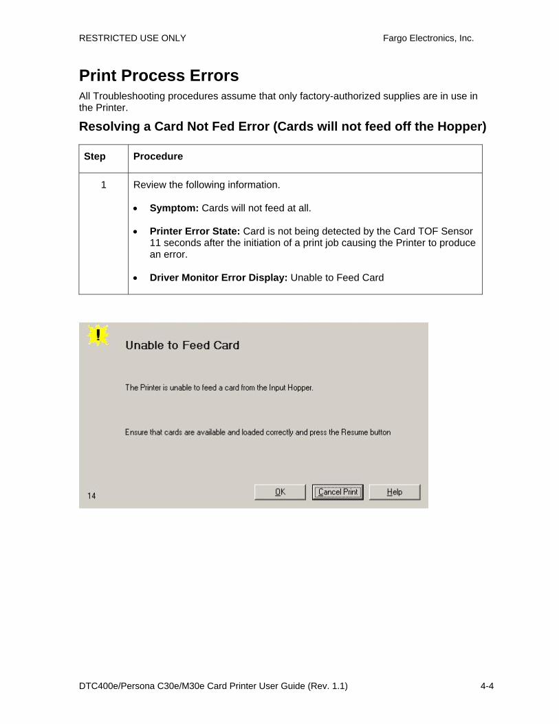
1 Review the following information.
• Symptom: Cards will not feed at all.
• Printer Error State: Card is not being detected by the Card TOF Sensor 11 seconds after the initiation of a print job causing the Printer to produce an error.
• Driver Monitor Error Display: Unable to Feed Card

RESTRICTED USE ONLY Fargo Electronics, Inc.
DTC400e/Persona C30e/M30e Card Printer User Guide (Rev. 1.1) 4-5
2 Check the card quality / loading.
a. Remove cards from the Card Hopper.
b. Ensure that the cards are not sticking together by fanning them out and then lining them back together in a straight deck.
c. Press the Card Hopper Load Lever down until the Card Tray locks into place.
d. Load up to 100 cards into the Hopper with the print side down.
e. Close the Card Hopper Cover to release the Card Tray.
f. Press on the Resume button.
g. If the cards do not feed, continue to Step 3.
3 Press the Cancel Print button on the Driver Monitor Error Display Message.
4 Reboot the Printer by cycling the power.
5 Check the Card Feed Motor.
a. Remove all cards from the Hopper.
b. Press the Card Hopper Load Lever down until the Card Tray locks into place.
c. Use the Fargo Workbench Printer Utility to send a test print to the Printer.
d. Gently touch the Card Hopper Feed Roller to verify that it is turning
e. If Roller is NOT turning, continue to Step 7.
f. If Roller is turning, continue to Step 6.
6 Check Hopper Tray Spring Tension.
a. Open Card Hopper Cover.
b. Use the Fargo Workbench Printer Utility to send a test print to the Printer.
c. When the Card Hopper Feed Roller engages, push up on the Card Hopper Tray.
g. If the cards feed, replace the Card Hopper Lift Spring.
d. If the cards do not feed, replace the Card Hopper Feed Roller.
7 Card Hopper Feed Roller is not turning during a print job.
a. Remove the Printer rear cover.
b. Ensure that the Card Hopper Feed Motor power cable is securely connected to J-20 on the Printers Main Board.
c. Ensure that the Card Hopper Feed Motor power cable is securely connected to the Card Hopper Feed Motor.
d. Use the Fargo Workbench Printer Utility to send a test print to the Printer.
e. If the Card Hopper Feed Motor is not moving, continue to Step 8.

RESTRICTED USE ONLY Fargo Electronics, Inc.
DTC400e/Persona C30e/M30e Card Printer User Guide (Rev. 1.1) 4-6
8 Replace Card Hopper Feed Motor.
a. Replace the Card Hopper Feed Motor.
b. Use the Fargo Workbench Printer Utility to send a test print to the Printer.
c. If the Card Hopper Feed Motor does not turn, replace the Main Board.
RESTRICTED USE ONLY Fargo Electronics, Inc.
DTC400e/Persona C30e/M30e Card Printer User Guide (Rev. 1.1) 4-7
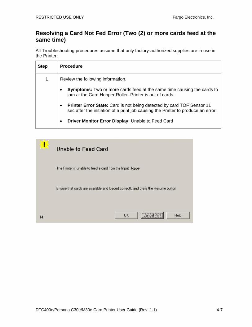
Resolving a Card Not Fed Error (Two (2) or more cards feed at the same time)
All Troubleshooting procedures assume that only factory-authorized supplies are in use in the Printer.
Step Procedure
1 Review the following information.
• Symptoms: Two or more cards feed at the same time causing the cards to jam at the Card Hopper Roller. Printer is out of cards.
• Printer Error State: Card is not being detected by card TOF Sensor 11 sec after the initiation of a print job causing the Printer to produce an error.
• Driver Monitor Error Display: Unable to Feed Card

RESTRICTED USE ONLY Fargo Electronics, Inc.
DTC400e/Persona C30e/M30e Card Printer User Guide (Rev. 1.1) 4-8
2 Check card quality / loading.
a. Remove cards from the Card Hopper.
b. Ensure that the cards are not sticking together by fanning them out and then lining them back together in a straight deck.
c. Press the Card Hopper Load Lever down until the Card Tray locks into place.
d. Load up to 100 cards into the Hopper with the print side down.
e. Close the Card Hopper Cover to release the Card Tray.
f. Press on the Resume button.
g. If the cards do not feed, continue to Step 3.
3 Press the Cancel Print button on the Driver Monitor Error Display Message.
4 Reboot the Printer by cycling the power.
5 Check Card Feed TOF Sensor.
a. Remove the Printers rear cover.
b. Use a digital volt meter to place the Positive lead to pin 9 of the J-4 Main Board connection and the negative lead to pin 12 of the J-4 Main Board connection.
• The blocked Sensor should read +4.99 vdc.
• The open Sensor should read +1.5 vdc.
c. If the Card Feed TOF Sensor does not read properly, replace the Sensor.
6 Clean the Card Feed Roller.
RESTRICTED USE ONLY Fargo Electronics, Inc.
DTC400e/Persona C30e/M30e Card Printer User Guide (Rev. 1.1) 4-9
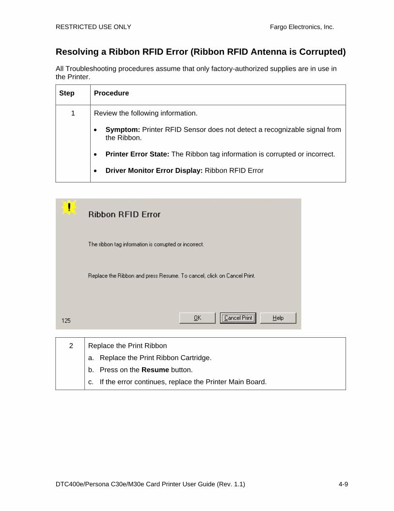
Resolving a Ribbon RFID Error (Ribbon RFID Antenna is Corrupted)
All Troubleshooting procedures assume that only factory-authorized supplies are in use in the Printer.
Step Procedure
1 Review the following information.
• Symptom: Printer RFID Sensor does not detect a recognizable signal from the Ribbon.
• Printer Error State: The Ribbon tag information is corrupted or incorrect.
• Driver Monitor Error Display: Ribbon RFID Error
2 Replace the Print Ribbon
a. Replace the Print Ribbon Cartridge.
b. Press on the Resume button.
c. If the error continues, replace the Printer Main Board.
RESTRICTED USE ONLY Fargo Electronics, Inc.
DTC400e/Persona C30e/M30e Card Printer User Guide (Rev. 1.1) 4-10
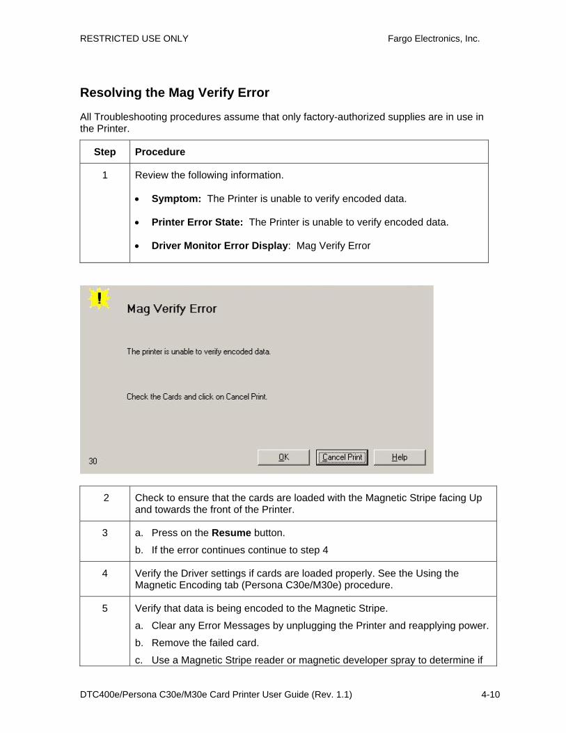
Resolving the Mag Verify Error
All Troubleshooting procedures assume that only factory-authorized supplies are in use in the Printer.
Step Procedure
1 Review the following information.
• Symptom: The Printer is unable to verify encoded data.
• Printer Error State: The Printer is unable to verify encoded data.
• Driver Monitor Error Display: Mag Verify Error
2 Check to ensure that the cards are loaded with the Magnetic Stripe facing Up and towards the front of the Printer.
3 a. Press on the Resume button.
b. If the error continues continue to step 4
4 Verify the Driver settings if cards are loaded properly. See the Using the Magnetic Encoding tab (Persona C30e/M30e) procedure.
5 Verify that data is being encoded to the Magnetic Stripe.
a. Clear any Error Messages by unplugging the Printer and reapplying power.
b. Remove the failed card.
c. Use a Magnetic Stripe reader or magnetic developer spray to determine if
RESTRICTED USE ONLY Fargo Electronics, Inc.
DTC400e/Persona C30e/M30e Card Printer User Guide (Rev. 1.1) 4-11
data is being written to the Magnetic Stripe.
d. If data is not being written to the Magnetic Stripe,
• Open the front cover.
• Verify that the Magnetic Module is seated securely into the Magnetic Module docking station.
e. If the Magnetic Module is properly seated, replace the magnetic head (as needed). (Note: in the Parts Replacement Section.)
f. If data is being written to the Magnetic Stripe, the Magnetic Offset may need to be adjusted. See the Using the Mag Top of Form Option procedure.
6 Verify that the coercivity of the cards matches the Driver Settings.
RESTRICTED USE ONLY Fargo Electronics, Inc.
DTC400e/Persona C30e/M30e Card Printer User Guide (Rev. 1.1) 4-12

RESTRICTED USE ONLY Fargo Electronics, Inc.
DTC400e/Persona C30e/M30e Card Printer User Guide (Rev. 1.1) 4-13
Resolving the No Magnetic Encoder Installed Error
All Troubleshooting procedures assume that only factory-authorized supplies are in use in the Printer.
Step Procedure
1 Review the following information.
• Symptom: There is not a Magnetic Encoder installed.
• Printer Error State: A print job with Magnetic encoding was sent with no Magnetic encoder installed in the Printer.
• Driver Monitor Error Display: No Magnetic Encoder Installed
2 Press the Cancel Print button on the Driver Monitor Error Display Message.
3 Reboot the Printer by cycling the power.
4 Verify that the Printer has a Magnetic Encoder installed.
a. Open the front cover.
b. Verify that the Printer has a Magnetic Module installed. (Note: If the Printer is equipped with a Magnetic Encoder Module, ensure that it is seated securely into the Magnetic Module docking station. If the issue persists, replace the Magnetic Module. See the Persona C30e/M30e service manual for replacement procedures.)
5 If the Printer has no Magnetic Encoder Module, verify that the encoding data

RESTRICTED USE ONLY Fargo Electronics, Inc.
DTC400e/Persona C30e/M30e Card Printer User Guide (Rev. 1.1) 4-14
was sent in error, check the appropriate software user’s manual for encoding instructions.

RESTRICTED USE ONLY Fargo Electronics, Inc.
DTC400e/Persona C30e/M30e Card Printer User Guide (Rev. 1.1) 4-15
Resolving the No Mag Stripe Present Error
All Troubleshooting procedures assume that only factory-authorized supplies are in use in the Printer.
Step Procedure
1 Review the following information.
• Symptom: There is no magnetic card in the printer.
• Printer Error State: A print job with Magnetic encoding data was sent to the printer but the card does not have a magnetic stripe on it.
• Driver Monitor Error Display: No Mag Strip Present
2 • Verify card has magnetic stripe and it is placed in the hopper correctly. Magnetic stripe must face UP.

RESTRICTED USE ONLY Fargo Electronics, Inc.
DTC400e/Persona C30e/M30e Card Printer User Guide (Rev. 1.1) 4-16
Resolving the No Smart Card Encoder Error
All Troubleshooting procedures assume that only factory-authorized supplies are in use in the Printer.
Step Procedure
1 Review the following information.
• Symptom: There is not a Smart Card Encoder installed.
• Printer Error State: A print job with Smart Card encoding was sent with no encoder installed in the Printer.
• Driver Monitor Error Display: No Smart Card Encoder Installed
2 Press the Cancel Print button on the Driver Monitor Error Display Message.
3 Reboot the Printer by cycling the power.
4 Verify that the Printer has a Smart Card Encoder installed.
c. Open the front cover.
d. Verify that the Printer has a Smart Card Module installed. (Note: If the Printer is equipped with a Smart Card Encoder Module, ensure that it is seated securely into the Module docking station. If the issue persists, replace the Smart Card Module. See the Persona C30e/M30e service manual for replacement procedures.)
5 If the Printer has no Smart Card Encoder Module, verify that the encoding data was sent in error, check the appropriate software user’s manual for encoding instructions.

RESTRICTED USE ONLY Fargo Electronics, Inc.
DTC400e/Persona C30e/M30e Card Printer User Guide (Rev. 1.1) 4-17

RESTRICTED USE ONLY Fargo Electronics, Inc.
DTC400e/Persona C30e/M30e Card Printer User Guide (Rev. 1.1) 4-18
Resolving the No Prox Card Encoder Error All Troubleshooting procedures assume that only factory-authorized supplies are in use in the Printer.
Step Procedure
1 Review the following information.
• Symptom: There is not a Prox Card Encoder installed.
• Printer Error State: A print job with Prox Card encoding was sent with no encoder installed in the Printer.
• Driver Monitor Error Display: No Prox Card Encoder Installed
2 Press the Cancel Print button on the Driver Monitor Error Display Message.
3 Reboot the Printer by cycling the power.
4 Verify that the Printer has a Prox Card Encoder installed.
e. Open the front cover.
f. Verify that the Printer has a Prox Card Module installed. (Note: If the Printer is equipped with a Prox Card Encoder Module, ensure that it is seated securely into the Module docking station. If the issue persists, replace the Prox Card Module. See the Persona C30e/M30e service manual for replacement procedures.)
5 If the Printer has no Prox Card Encoder Module, verify that the encoding data was sent in error, check the appropriate software user’s manual for encoding instructions.

RESTRICTED USE ONLY Fargo Electronics, Inc.
DTC400e/Persona C30e/M30e Card Printer User Guide (Rev. 1.1) 4-19

RESTRICTED USE ONLY Fargo Electronics, Inc.
DTC400e/Persona C30e/M30e Card Printer User Guide (Rev. 1.1) 4-20
Resolving a Ribbon Sensor Error (Ribbon Miscue) DTC400e & C30e All Troubleshooting procedures assume that only factory-authorized supplies are in use in the Printer. (Note: Using the printer in direct sunlight may adversely affect the ribbon sensor integrity.)
Step Procedure
1 Review the following information.
• Symptom: The Printer rolls through Ribbon and errors out.
• Printer Error State: The Printer cannot find the next panel on the Ribbon.
• Driver Monitor Error Display: Ribbon Sensor Error
2 Open the front cover and remove the Ribbon Cartridge.
a. Check that the Ribbon is in good condition and not wrinkled or broken.
b. If Ribbon is broke or wrinkled, repair the Ribbon and wind up the take-up roll 4-color panels past the damaged area.
3 Press on the Resume button.
If the issue persists, continue to Step 4.

RESTRICTED USE ONLY Fargo Electronics, Inc.
DTC400e/Persona C30e/M30e Card Printer User Guide (Rev. 1.1) 4-21
4 Replace the Ribbon Cartridge.
a. Press on the Resume button.
b. If the issue persists, continue to Step 5.
5 Press the Cancel Print button on the Driver Monitor Error Display Message.
6 Reboot the Printer by cycling the power.
7 Use the Driver Calibration tab to calibrate the Ribbon Sensor. Cover the front of the printer to block the light while calibrating this sensor.
• If the issue persists, continue to Step 8.
8 Replace the Ribbon Sensor.
Resolving a Ribbon Break Jam Error
All Troubleshooting procedures assume that only factory-authorized supplies are in use in the Printer. (Note: Using the printer in direct sunlight may adversely affect the ribbon sensor integrity.)
Step Procedure
1 Review the following information.
• Symptom: The Print Ribbon has become jammed or has broken in the Printer.
• Printer Error State: The Ribbon Supply Encoder Sensor has unexpectedly stop receiving information from the Ribbon Encoder
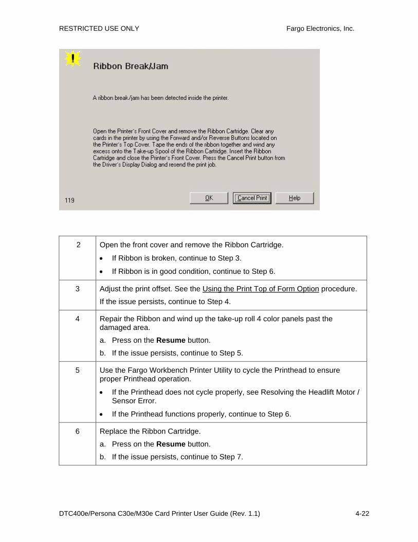
• Driver Monitor Error Display: Ribbon Break/Jam
RESTRICTED USE ONLY Fargo Electronics, Inc.
DTC400e/Persona C30e/M30e Card Printer User Guide (Rev. 1.1) 4-22
2 Open the front cover and remove the Ribbon Cartridge.
• If Ribbon is broken, continue to Step 3.
• If Ribbon is in good condition, continue to Step 6.
3 Adjust the print offset. See the Using the Print Top of Form Option procedure.
If the issue persists, continue to Step 4.
4 Repair the Ribbon and wind up the take-up roll 4 color panels past the damaged area.
a. Press on the Resume button.
b. If the issue persists, continue to Step 5.
5 Use the Fargo Workbench Printer Utility to cycle the Printhead to ensure proper Printhead operation.
• If the Printhead does not cycle properly, see Resolving the Headlift Motor / Sensor Error.
• If the Printhead functions properly, continue to Step 6.
6 Replace the Ribbon Cartridge.
a. Press on the Resume button.
b. If the issue persists, continue to Step 7.

RESTRICTED USE ONLY Fargo Electronics, Inc.
DTC400e/Persona C30e/M30e Card Printer User Guide (Rev. 1.1) 4-23
7 Remove the rear cover in order to check that the Ribbon Encoder Sensor is securely connected to the J-4 Main Board connection and to the Encoder Sensor.
a. Press on the Resume button.
b. If the issue persists, replace the Encoder Sensor.

RESTRICTED USE ONLY Fargo Electronics, Inc.
DTC400e/Persona C30e/M30e Card Printer User Guide (Rev. 1.1) 4-24
Resolving a Ribbon Out Error
All Troubleshooting procedures assume that only factory-authorized supplies are in use in the Printer. (Note: Using the printer in direct sunlight may adversely affect the ribbon sensor integrity.)
Step Procedure
1 Review the following information.
• Symptom: Printer will not print.
• Printer Error State: The Ribbon Sensor has detected the End of Ribbon mark.
• Driver Monitor Error Display: Ribbon Out
2 Replace the Ribbon Cartridge
a. Press on the Resume button.

RESTRICTED USE ONLY Fargo Electronics, Inc.
DTC400e/Persona C30e/M30e Card Printer User Guide (Rev. 1.1) 4-25
Resolving a No Ribbon Installed Error
All Troubleshooting procedures assume that only factory-authorized supplies are in use in the Printer.
Step Procedure
1 Review the following information.
• Symptom: Printer errors out as soon as it receives data from PC.
• Printer Error State: The Printer RFID Sensor is not receiving a signal from the Ribbon.
• Driver Monitor Error Display: No Ribbon Installed
2 Verify that a Ribbon Cartridge is installed in the Printer.
a. Press on the Resume button.
b. If the issue persists, continue to Step 3.
3 Remove the rear cover and check that the Ribbon RFID cable is securely connected to the Main Board (J-5) and the RFID Sensor.
• If the connections are loose, reattach them.
• Press on the Resume button.
• If the connections are good or if the issue persists, continue to Step 4.
4 Replace the Ribbon RFID Sensor.

RESTRICTED USE ONLY Fargo Electronics, Inc.
DTC400e/Persona C30e/M30e Card Printer User Guide (Rev. 1.1) 4-26
Resolving a Invalid Ribbon Error
All Troubleshooting procedures assume that only factory-authorized supplies are in use in the Printer.
Step Procedure
1 Review the following information.
• Symptom: Printer errors out as soon as it receives data from the PC.
• Printer Error State: The Ribbon installed does not match the Printer model.
• Driver Monitor Error Display: Invalid Ribbon
2 Verify that the Ribbon Cartridge installed is designed for the correct Printer model.
3 Press on the Resume button.
If the issue persists, continue to Step 4.
4 Remove the rear cover and check that the Ribbon RFID cable is securely connected to the Main Board (J-5) and the RFID Sensor.
• If the connections are loose, reattach.

RESTRICTED USE ONLY Fargo Electronics, Inc.
DTC400e/Persona C30e/M30e Card Printer User Guide (Rev. 1.1) 4-27
• Press on the Resume button.
• If the connections are good or if the issue persists, continue to Step 5.
5 Replace the Ribbon RFID Sensor.

RESTRICTED USE ONLY Fargo Electronics, Inc.
DTC400e/Persona C30e/M30e Card Printer User Guide (Rev. 1.1) 4-28
Resolving a Wrong Ribbon Error
All Troubleshooting procedures assume that only factory-authorized supplies are in use in the Printer.
Step Procedure
1 Review the following information.
• Symptom: Printer errors out as soon as it receives data from the PC.
• Printer Error State: The Ribbon installed does not match the Printer Driver information.
• Driver Monitor Error Display: Wrong Ribbon Installed
2 Verify the Driver settings are correct.
a. Open the Printer Control Panel from the Computer.
• If using Windows 2000/XP, right click on the DTC400e/C30e/M30e Card Printer and select Printing Preferences.
b. Click on the Device Option tab.
c. Click on the auto select button.
d. Check that the Ribbon type matches the Ribbon selected.
3 Press on the Resume button.
If the issue persists, continue to Step 4.

RESTRICTED USE ONLY Fargo Electronics, Inc.
DTC400e/Persona C30e/M30e Card Printer User Guide (Rev. 1.1) 4-29
4 Remove the rear cover and check that the Ribbon RFID cable is securely connected to the Main Board (J-5) and the RFID Sensor.
• If the connections are loose, reattach it.
• Press on the Resume button.
• If the connections are good or if the issue persists, continue to Step 5.
5 Replace the Ribbon RFID Sensor.
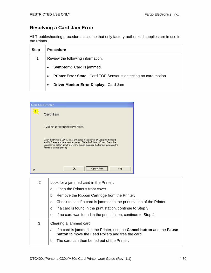
RESTRICTED USE ONLY Fargo Electronics, Inc.
DTC400e/Persona C30e/M30e Card Printer User Guide (Rev. 1.1) 4-30
Resolving a Card Jam Error
All Troubleshooting procedures assume that only factory-authorized supplies are in use in the Printer.
Step Procedure
1 Review the following information.
• Symptom: Card is jammed.
• Printer Error State: Card TOF Sensor is detecting no card motion.
• Driver Monitor Error Display: Card Jam
2 Look for a jammed card in the Printer.
a. Open the Printer’s front cover.
b. Remove the Ribbon Cartridge from the Printer.
c. Check to see if a card is jammed in the print station of the Printer.
d. If a card is found in the print station, continue to Step 3.
e. If no card was found in the print station, continue to Step 4.
3 Clearing a jammed card.
a. If a card is jammed in the Printer, use the Cancel button and the Pause button to move the Feed Rollers and free the card.
b. The card can then be fed out of the Printer.

RESTRICTED USE ONLY Fargo Electronics, Inc.
DTC400e/Persona C30e/M30e Card Printer User Guide (Rev. 1.1) 4-31
4 Test the Card Sensor.
a. Remove the rear cover.
b. Using a Digital Voltmeter, connect the negative lead to ground.
c. Connect the positive lead to Pin 10 of J4.
• If blocked, the Sensor should read 4.9 to 5.5 VDC.
• If unblocked, the Sensor should read 0.15 to 0.18 VDC.
d. If the voltages do not read correctly, replace the Sensor. (Note: Contact an authorized repair center)

RESTRICTED USE ONLY Fargo Electronics, Inc.
DTC400e/Persona C30e/M30e Card Printer User Guide (Rev. 1.1) 4-32
Resolving a Card Jam (Encoder) Error
All Troubleshooting procedures assume that only factory-authorized supplies are in use in the Printer.
Step Procedure
1 Review the following information.
• Symptom: Card is jammed in the Printer Encoding Station
• Printer Error State: Card TOF Sensor is detecting no card motion.
• Driver Monitor Error Display: Card Jam (Encoder)
Step Procedure
2 a. Look for a jammed card in the Printer.
b. Open the Printer’s front cover.
c. Remove the Ribbon Cartridge from the Printer.
d. Check to see if a card is jammed in the encoding station of the Printer.
3 Clearing a jammed card.
a. If a card is jammed in the station, use the Forward button and/or Reverse button to move the Feed Rollers and free the card.
b. Re-insert the ribbon and close the printer cover.
c. Press the Resume button to continue printing.

RESTRICTED USE ONLY Fargo Electronics, Inc.
DTC400e/Persona C30e/M30e Card Printer User Guide (Rev. 1.1) 4-33
d. To cancel the print, press the Cancel button from the Driver dialog or Cancel the button on the Printer.
4 Test the Card Sensor.
e. Remove the rear cover.
f. Using a Digital Voltmeter, connect the negative lead to ground.
g. Connect the positive lead to Pin 10 of J4.
• If blocked, the Sensor should read 4.9 to 5.5 VDC.
• If unblocked, the Sensor should read 0.15 to 0.18 VDC.
h. If the voltages do not read correctly, replace the Sensor. (Note: Contact an authorized repair center)

RESTRICTED USE ONLY Fargo Electronics, Inc.
DTC400e/Persona C30e/M30e Card Printer User Guide (Rev. 1.1) 4-34
Resolving a Headlift Motor or Sensor Error
All Troubleshooting procedures assume that only factory-authorized supplies are in use in the Printer.
Step Procedure
1 Review the following information.
• Symptom: The Printhead continuously cycles or does not cycle at all.
• Printer Error State: Headlift Sensor is not detecting movement from the Headlift Cam.
• Driver Monitor Error Display: Headlift Error
2 Press the Cancel Print button on the Driver Monitor Error Display Message.
3 Reboot the Printer by cycling the power.
4 Cycle the Headlift Motors.
a. Use the Fargo Diagnostic utility to cycle the Printhead to ensure proper printhead operation.
a. Verify that the Headlift Motor turns.

RESTRICTED USE ONLY Fargo Electronics, Inc.
DTC400e/Persona C30e/M30e Card Printer User Guide (Rev. 1.1) 4-35
b. If the Motor does not turn or jams, continue to Step 5.
5 Check the Headlift Motor Main Board Connection (J20).
a. Unplug the Printer.
b. Remove the back cover.
c. Verify that connection J20 is properly connected to the Main Board.
d. If the Motor does not turn, continue to Step 7.
6 Test the Headlift Sensor.
a. Remove the back cover.
b. Attach the positive lead from a Digital Voltmeter to Pin 1 of J9. Attach the negative lead to the Pin 3 of J9.
• If open, the Sensor should read 0.17 to 0.9 VDC.
• If closed, the Sensor should read 4.9 to 5.5 VDC.
c. Replace the Sensor if the voltages do not read correctly. (Note: Contact an authorized repair center)
d. If the Motor does turn, continue to Step 7.
7 Replace the Headlift Motor (Note: Contact an authorized repair center)
a. If the Motor does turn, continue to Step 8.
8 Replace the Main Board. (Note: Contact an authorized repair center)

RESTRICTED USE ONLY Fargo Electronics, Inc.
DTC400e/Persona C30e/M30e Card Printer User Guide (Rev. 1.1) 4-36
Resolving the Cover Open issue
All Troubleshooting procedures assume that only factory-authorized supplies are in use in the Printer.
Step Procedure
1 Review the following information.
• Symptom: The Printer remains idle after a print job is sent.
• Printer Error State: The front cover Sensor detects that the cover is open.
• Driver Monitor Error Display: None
2 Check for debris, as follows:
a. Open the front cover and check that no debris has accumulated in the Sensor opening. Use compressed air to clean the opening as needed.
b. If the Sensor still does not work, continue to Step 3.
3 Check that the Sensor tab on the front cover is not damaged.
a. Open the front cover and examine the Lid Sensor tab for damage, if the Sensor tab is damaged, replace the front cover. (Note: in the Parts Replacement Section.)
b. If the Sensor still does not work, continue to Step 4.
4 Replace the Main Board. . (Note: Contact an authorized repair center)
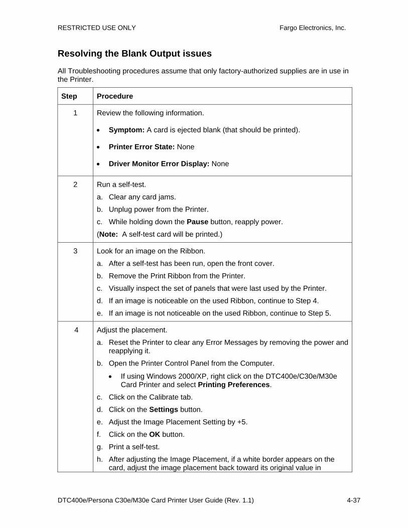
RESTRICTED USE ONLY Fargo Electronics, Inc.
DTC400e/Persona C30e/M30e Card Printer User Guide (Rev. 1.1) 4-37
Resolving the Blank Output issues
All Troubleshooting procedures assume that only factory-authorized supplies are in use in the Printer.
Step Procedure
1 Review the following information.
• Symptom: A card is ejected blank (that should be printed).
• Printer Error State: None
• Driver Monitor Error Display: None
2 Run a self-test.
a. Clear any card jams.
b. Unplug power from the Printer.
c. While holding down the Pause button, reapply power.
(Note: A self-test card will be printed.)
3 Look for an image on the Ribbon.
a. After a self-test has been run, open the front cover.
b. Remove the Print Ribbon from the Printer.
c. Visually inspect the set of panels that were last used by the Printer.
d. If an image is noticeable on the used Ribbon, continue to Step 4.
e. If an image is not noticeable on the used Ribbon, continue to Step 5.
4 Adjust the placement.
a. Reset the Printer to clear any Error Messages by removing the power and reapplying it.
b. Open the Printer Control Panel from the Computer.
• If using Windows 2000/XP, right click on the DTC400e/C30e/M30e Card Printer and select Printing Preferences.
c. Click on the Calibrate tab.
d. Click on the Settings button.
e. Adjust the Image Placement Setting by +5.
f. Click on the OK button.
g. Print a self-test.
h. After adjusting the Image Placement, if a white border appears on the card, adjust the image placement back toward its original value in

RESTRICTED USE ONLY Fargo Electronics, Inc.
DTC400e/Persona C30e/M30e Card Printer User Guide (Rev. 1.1) 4-38
increments of 2 until the white edge is gone.
i. If still having blank card issues, continue to Step 5.
5 Check the Printhead connections.
a. Remove the Printer power and USB cables.
b. Turn the Printer over to gain access to the base plate.
c. Remove the one (1) screw from the Printhead cover plate and remove the cover plate.
d. Depress the Printhead locking tabs and remove the Printhead.
e. Check to ensure that Power and Data Cable (that connects to the Printhead) is properly seated.
f. Remove the Back Cover.
g. Ensure that the Printhead Power/Data Cable is properly seated on J16 on the Main board.
h. If still having blank card issues, continue to Step 6.
6 Ensure that the proper voltage is being applied to the Printhead.
a. Remove the back cover.
b. Using a Digital Voltmeter, connect the negative lead to ground.
c. Probe Pins 1 to 5 of the Printhead power connection on J16.
d. Ensure that a voltage between 22 to 23 VDC is read on each pin.
• If less than 22 volts is read on any of the pins, replace the Printhead.
• If still having issue with blank cards, replace the Main Board. (Note: Contact an authorized repair center)

RESTRICTED USE ONLY Fargo Electronics, Inc.
DTC400e/Persona C30e/M30e Card Printer User Guide (Rev. 1.1) 4-39
Resolving the Remove Ribbon Message (Rewriteable Job)
All Troubleshooting procedures assume that only factory-authorized supplies are in use in the Printer.
Step Procedure
1 Review the following information.
• Symptom: An error message will be displayed when a rewriteable job is submitted to the Printer and there is a Ribbon in the Printer.
• Printer Error State: The error message will instruct the user to remove the ribbon from the printer.
• Driver Monitor Error Display: Remove Ribbon

RESTRICTED USE ONLY Fargo Electronics, Inc.
DTC400e/Persona C30e/M30e Card Printer User Guide (Rev. 1.1) 4-40
Flipper Table Module Assembly Problems Resolving the No Flipper Table Module problem
All Troubleshooting procedures assume that only factory-authorized supplies are in use in the Printer.
Step Procedure
1 Review the following information.
• Symptom: The Flipper Table Module Assembly is not functioning.
• Printer Error State: The Printer is unable to communicate with the Flipper Module.
• Driver Monitor Error Display: No Flipper Module

RESTRICTED USE ONLY Fargo Electronics, Inc.
DTC400e/Persona C30e/M30e Card Printer User Guide (Rev. 1.1) 4-41
Resolving the Flipper Jam Error
All Troubleshooting procedures assume that only factory-authorized supplies are in use in the Printer.
Step Procedure
1 Review the following information.
• Symptom: The Flipper Table Module is jamming.
• Printer Error State: The Flipper Table has jammed while either aligning itself or flipping a card.
• Driver Monitor Error Display: Flipper Jam
2 Open the Printer’s Flipper Table Module Cover.
a. Clear any cards in the Flipper Table Module by using the Forward and/or Reverse buttons located on the Printer’s Top Cover.
b. Ensure that the Flipper Table Module can rotate freely.
c. Close the Printer’s Flipper Table Module.
d. Press the Resume button on the Printer’s Top Cover to continue printing.
e. To cancel the printing, press the Cancel Print button from the Driver’s display dialog.
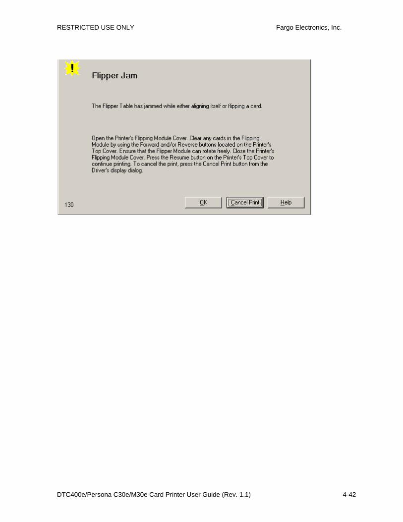
RESTRICTED USE ONLY Fargo Electronics, Inc.
DTC400e/Persona C30e/M30e Card Printer User Guide (Rev. 1.1) 4-42
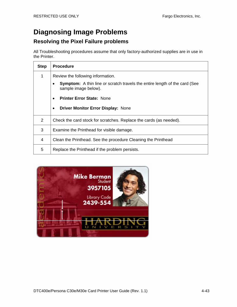
RESTRICTED USE ONLY Fargo Electronics, Inc.
DTC400e/Persona C30e/M30e Card Printer User Guide (Rev. 1.1) 4-43
Diagnosing Image Problems Resolving the Pixel Failure problems
All Troubleshooting procedures assume that only factory-authorized supplies are in use in the Printer.
Step Procedure
1 Review the following information.
• Symptom: A thin line or scratch travels the entire length of the card (See sample image below).
• Printer Error State: None
• Driver Monitor Error Display: None
2 Check the card stock for scratches. Replace the cards (as needed).
3 Examine the Printhead for visible damage.
4 Clean the Printhead. See the procedure Cleaning the Printhead
5 Replace the Printhead if the problem persists.
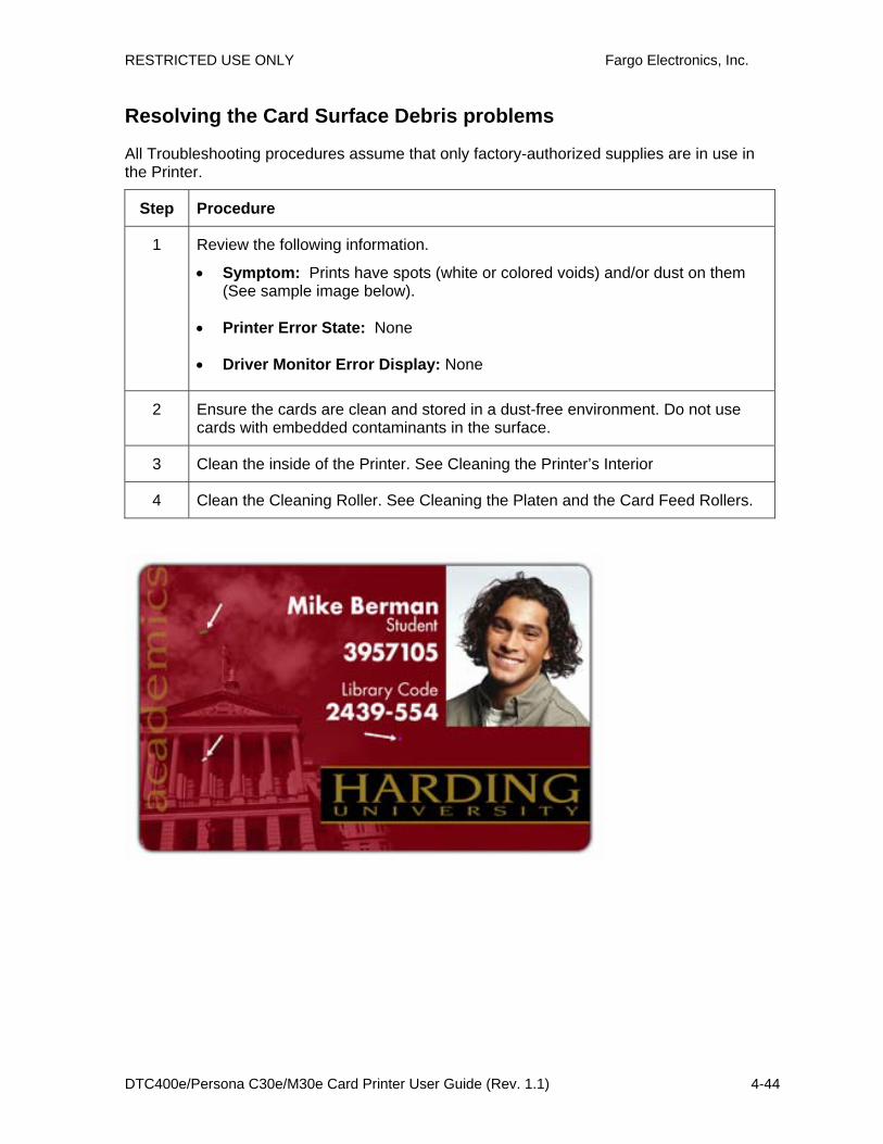
RESTRICTED USE ONLY Fargo Electronics, Inc.
DTC400e/Persona C30e/M30e Card Printer User Guide (Rev. 1.1) 4-44
Resolving the Card Surface Debris problems
All Troubleshooting procedures assume that only factory-authorized supplies are in use in the Printer.
Step Procedure
1 Review the following information.
• Symptom: Prints have spots (white or colored voids) and/or dust on them (See sample image below).
• Printer Error State: None
• Driver Monitor Error Display: None
2 Ensure the cards are clean and stored in a dust-free environment. Do not use cards with embedded contaminants in the surface.
3 Clean the inside of the Printer. See Cleaning the Printer’s Interior
4 Clean the Cleaning Roller. See Cleaning the Platen and the Card Feed Rollers.

RESTRICTED USE ONLY Fargo Electronics, Inc.
DTC400e/Persona C30e/M30e Card Printer User Guide (Rev. 1.1) 4-45
Resolving the Incorrect Image Darkness problems
All Troubleshooting procedures assume that only factory-authorized supplies are in use in the Printer.
Step Procedure
1 Review the following information.
• Symptom: Printed cards are too dark or too light.
• Printer Error State: None
• Driver Monitor Error Display: None
2 Run a self-test to ensure that the issue is not with the Driver settings.
3 Adjust the Dye-Sub Intensity setting within the Image Color tab of the Printer Driver. See Using the Image Color tab (C30e/M30e) procedure.
4 Correct the Image Darkness. See the Using the Image Darkness Option procedure.
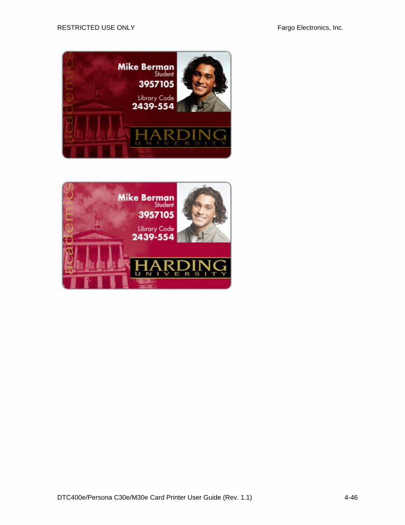
RESTRICTED USE ONLY Fargo Electronics, Inc.
DTC400e/Persona C30e/M30e Card Printer User Guide (Rev. 1.1) 4-46
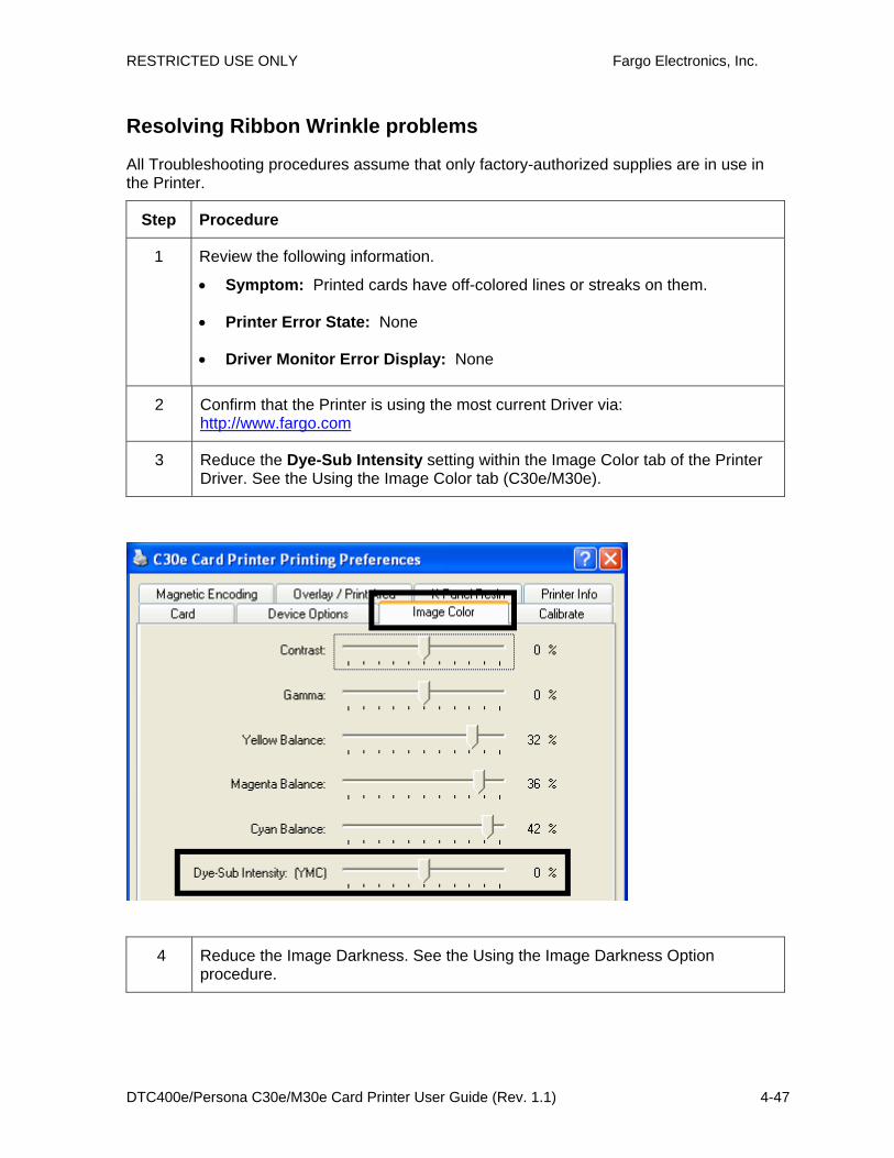
RESTRICTED USE ONLY Fargo Electronics, Inc.
DTC400e/Persona C30e/M30e Card Printer User Guide (Rev. 1.1) 4-47
Resolving Ribbon Wrinkle problems
All Troubleshooting procedures assume that only factory-authorized supplies are in use in the Printer.
Step Procedure
1 Review the following information.
• Symptom: Printed cards have off-colored lines or streaks on them.
• Printer Error State: None
• Driver Monitor Error Display: None
2 Confirm that the Printer is using the most current Driver via: http://www.fargo.com
3 Reduce the Dye-Sub Intensity setting within the Image Color tab of the Printer Driver. See the Using the Image Color tab (C30e/M30e).
4 Reduce the Image Darkness. See the Using the Image Darkness Option procedure.
RESTRICTED USE ONLY Fargo Electronics, Inc.
DTC400e/Persona C30e/M30e Card Printer User Guide (Rev. 1.1) 4-48

RESTRICTED USE ONLY Fargo Electronics, Inc.
DTC400e/Persona C30e/M30e Card Printer User Guide (Rev. 1.1) 4-49
Resolving the Excessive Resin printing problems
All Troubleshooting procedures assume that only factory-authorized supplies are in use in the Printer.
Step Procedure
1 Review the following information.
• Symptom: Black resin text and barcodes appear smeared or too thick.
• Printer Error State: None
• Driver Monitor Error Display: None
2 Reduce the Resin Heat setting within the Image Color tab of the Printer Driver. See the Using the Image Color tab (C30e/M30e).
3 Reduce the Image Darkness.

RESTRICTED USE ONLY Fargo Electronics, Inc.
DTC400e/Persona C30e/M30e Card Printer User Guide (Rev. 1.1) 4-50

RESTRICTED USE ONLY Fargo Electronics, Inc.
DTC400e/Persona C30e/M30e Card Printer User Guide (Rev. 1.1) 4-51
Resolving the Incomplete Resin printing problems
All Troubleshooting procedures assume that only factory-authorized supplies are in use in the Printer.
Step Procedure
1 Review the following information.
• Symptom: Black resin text and barcodes appear faded or too light.
• Printer Error State: None
• Driver Monitor Error Display: None
2 Increase the Resin Heat setting within the Image Color tab of the Printer Driver.
3 Increase the Image Darkness. See the Using the Image Darkness Option procedure.

RESTRICTED USE ONLY Fargo Electronics, Inc.
DTC400e/Persona C30e/M30e Card Printer User Guide (Rev. 1.1) 4-52
Resolving the Image Placement problems
All Troubleshooting procedures assume that only factory-authorized supplies are in use in the Printer. This procedure is used to adjust the position of the card in the Print driver and does not change the internal settings of the Printer. See Using the Printer Calibration Utility (Persona C30e/M30e) for instructions on changing the Printer’s internal settings.
Step Procedure
1 Review the following information.
• Symptom: Printing is cut off or is not centered on the card or a white border appears.
• Printer Error State: None
• Driver Monitor Error Display: None
2 Verify if the Image Position option within the Calibrate tab is set correctly or incorrectly.
a. Open the Printer Control Panel from the Computer.
• Right click on the DTC400e/C30e/M30e Card Printer and select Printing Preferences.
b. Click on the Calibrate tab.
c. Adjust the Vertical and/or Horizontal Image Position settings based on where the white border is on the card.

RESTRICTED USE ONLY Fargo Electronics, Inc.
DTC400e/Persona C30e/M30e Card Printer User Guide (Rev. 1.1) 4-53
3 Verify if the Horizontal Image Position Setting is set correctly or incorrectly. See the graphic below.
• If the white border is on the leading edge of the card, adjust the Horizontal value by +2.
• If the white border is on the trailing edge of the card, adjust the Horizontal value by -2.
a. Click on OK.
b. Run a self-test.
c. If the white border is diminished, continue the adjustment until it is gone.

RESTRICTED USE ONLY Fargo Electronics, Inc.
DTC400e/Persona C30e/M30e Card Printer User Guide (Rev. 1.1) 4-54
4 Verify if the Vertical Image Position Setting is set correctly or incorrectly. See the graphic below.
a. Adjust the value as described below:
• If the white border is on the top edge of the card, adjust the Vertical value by +2.
• If the white border is on the bottom edge of the card, adjust the Vertical value by -2.
b. Click on OK.
c. Run a self-test.
d. If the white border is diminished, continue the adjustment until it is gone.

RESTRICTED USE ONLY Fargo Electronics, Inc.
DTC400e/Persona C30e/M30e Card Printer User Guide (Rev. 1.1) 4-55

RESTRICTED USE ONLY Fargo Electronics, Inc.
DTC400e/Persona C30e/M30e Card Printer User Guide (Rev. 1.1) 4-56
Resolving the Poor Image Quality problems
All Troubleshooting procedures assume that only factory-authorized supplies are in use in the Printer.
Step Procedure
1 Review the following information.
• Symptom: Photos on the cards look pixilated or grainy, as shown below.
• Printer Error State: None
• Driver Monitor Error Display: None
2 Use high-resolution, 24-bit color images to always capture an image:
• at a 24-bit color setting
• at 300 dpi
• at the same size that it will be printed on the card, as captured either with a scanner or with a digital camera
If a small or low-resolution image is stretched or blown up, a pixilated or grainy effect will occur when printing, as shown below (rightside).

RESTRICTED USE ONLY Fargo Electronics, Inc.
DTC400e/Persona C30e/M30e Card Printer User Guide (Rev. 1.1) 4-57
Running the Self Test Perform a self-test after (a) an initial setup of the Printer, (b) a calibration procedure has been conducted or (c) a part has been replaced to check for proper Printer operation.
Step Procedure
1 Verify that a full-color or Premium Resin Ribbon Cartridge is installed and that cards are properly loaded.
Caution: If the power is ON, disconnect the Power Cable from the Printer’s rear panel.
2 Press and hold the Pause/Resume button.
3 While holding down the Pause/Resume button, plug the power cable back into the Printer.
4 • Full Color Ribbon Cartridge installed: The Printer will print a 3-color process gray scale on the front of the card. The overlay pass is not printed during the Self-test. (See Display A & B below)
• Premium Resin Ribbon Cartridge installed: The Printer will print a single color gray scale on the front of the card.

RESTRICTED USE ONLY Fargo Electronics, Inc.
DTC400e/Persona C30e/M30e Card Printer User Guide (Rev. 1.1) 4-58
Running the Standard Self Test Print
Display A: Full Color Test Print DTC400e & C30e
Display B: Test Print M30e

RESTRICTED USE ONLY Fargo Electronics, Inc.
DTC400e/Persona C30e/M30e Card Printer User Guide (Rev. 1.1) 4-59
Running the Magnetic Self Test (HiCo Only)
Perform a self-test after (a) an initial setup of the Printer, (b) a calibration procedure has been conducted or (c) a part has been replaced to check for proper Printer operation.
Step Procedure
1 Remove Ribbon Cartridge from the Printer and close the front cover
Caution: If the power is ON, disconnect the Power Cable from the Printer’s rear panel.
2 Press and hold the Pause/Resume button.
3 While holding down the Pause/Resume button, plug the power cable back into the Printer.
4 The Printer will Encode magnetic information on all 3 magnetic tracks.
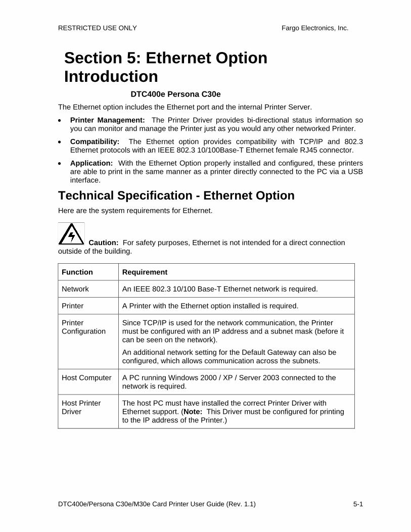
RESTRICTED USE ONLY Fargo Electronics, Inc.
DTC400e/Persona C30e/M30e Card Printer User Guide (Rev. 1.1) 5-1
Section 5: Ethernet Option Introduction
DTC400e Persona C30e The Ethernet option includes the Ethernet port and the internal Printer Server.
• Printer Management: The Printer Driver provides bi-directional status information so you can monitor and manage the Printer just as you would any other networked Printer.
• Compatibility: The Ethernet option provides compatibility with TCP/IP and 802.3 Ethernet protocols with an IEEE 802.3 10/100Base-T Ethernet female RJ45 connector.
• Application: With the Ethernet Option properly installed and configured, these printers are able to print in the same manner as a printer directly connected to the PC via a USB interface.
Technical Specification - Ethernet Option Here are the system requirements for Ethernet.
Caution: For safety purposes, Ethernet is not intended for a direct connection outside of the building.
Function Requirement
Network An IEEE 802.3 10/100 Base-T Ethernet network is required.
Printer A Printer with the Ethernet option installed is required.
Printer Configuration
Since TCP/IP is used for the network communication, the Printer must be configured with an IP address and a subnet mask (before it can be seen on the network).
An additional network setting for the Default Gateway can also be configured, which allows communication across the subnets.
Host Computer A PC running Windows 2000 / XP / Server 2003 connected to the network is required.
Host Printer Driver
The host PC must have installed the correct Printer Driver with Ethernet support. (Note: This Driver must be configured for printing to the IP address of the Printer.)
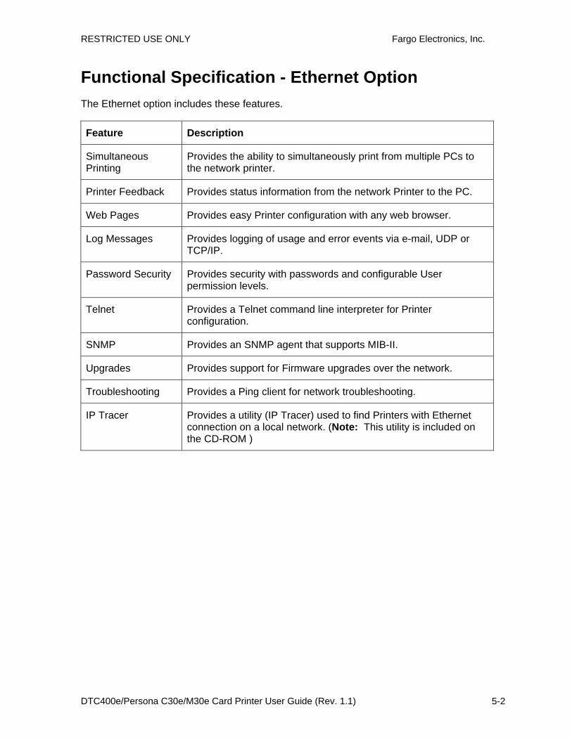
RESTRICTED USE ONLY Fargo Electronics, Inc.
DTC400e/Persona C30e/M30e Card Printer User Guide (Rev. 1.1) 5-2
Functional Specification - Ethernet Option The Ethernet option includes these features.
Feature Description
Simultaneous Printing
Provides the ability to simultaneously print from multiple PCs to the network printer.
Printer Feedback Provides status information from the network Printer to the PC.
Web Pages Provides easy Printer configuration with any web browser.
Log Messages Provides logging of usage and error events via e-mail, UDP or TCP/IP.
Password Security Provides security with passwords and configurable User permission levels.
Telnet Provides a Telnet command line interpreter for Printer configuration.
SNMP Provides an SNMP agent that supports MIB-II.
Upgrades Provides support for Firmware upgrades over the network.
Troubleshooting Provides a Ping client for network troubleshooting.
IP Tracer Provides a utility (IP Tracer) used to find Printers with Ethernet connection on a local network. (Note: This utility is included on the CD-ROM )

RESTRICTED USE ONLY Fargo Electronics, Inc.
DTC400e/Persona C30e/M30e Card Printer User Guide (Rev. 1.1) 5-3
Network Services - Overview The Ethernet option provides the services described in this section. (Note: Other additional services include a Ping client, address assignment and Printer discovery functions.)
Reviewing the Print Server
The Print Server provides printing services in the same manner as a printer connected directly to a USB interface except that the Printer is connected through the local area network to the client PC. The Print Server must be properly configured in order to provide this printing capability.
• The Print Server is capable of queuing up to eight (8) client PCs while printing. Communications between each PC and the Ethernet-enabled Printer are implemented over a bi-directional TCP/IP interface.
• All clients are able to send print jobs to the Printer and monitor Printer jobs and errors with the standard Windows printing system using the Printer Driver installed on their local PC.
In this way, the User knows whether or not a print job has been successful. Also, the User knows what problems have been encountered while processing the print job. Printing using Ethernet works in a manner similar to the USB-connected PC/printer.
Reviewing the Web Page Server
An HTTP service serves web pages that provide an interface through which to configure and monitor the Printer. (Note: Users may also monitor all print jobs that have been sent to the Printer from any client PC.)
Reviewing the Network Management Interface
The Ethernet-enabled Printer operates as an SNMP agent to allow central administrators to monitor and configure the network interface and the Printer. (Note: A standard host MIB-II is implemented to maximize the utility of the Printer on the network.)
Reviewing the Telnet Server
The Ethernet interface has a command line interpreter. (Note: The User can connect to the Printer using a Telnet session on their PC, issue commands to the Printer and receive response from the Printer.)
The Telnet commands are primarily used for network administration, and they will not be used by most Users. (Note: These commands will query the state of the Printer and configure various settings for the Printer. These include network settings, logging setting, User names and User passwords.)

RESTRICTED USE ONLY Fargo Electronics, Inc.
DTC400e/Persona C30e/M30e Card Printer User Guide (Rev. 1.1) 5-4
Network Management Interface The SNMP interface is described below.
Interface Description
SNMP • The Ethernet interface is a fully-manageable SNMP agent that supports MIB-II.
• The Ethernet interface is MIB II compliant, allowing SNMP managers to monitor protocol, network and routing statistics.
Telnet Command Line Interface Initiating a Telnet Session
This procedure shows how to initiate a Telnet session from a PC in order to access the Telnet services provided by the Printer. Follow these instructions to issue Telnet commands. See the next section for related Ethernet Printer Troubleshooting procedures.
Step Description
1 Identify the IP address of your Printer.
2 Initiate a Telnet session from a DOS window on your PC. At the DOS prompt, enter telnet [IP Address]
Example: C:\>telnet 192.168.11.12
• All Telnet responses from the Printer will then be displayed in the Telnet session on the PC.
• All commands entered will be sent to the Telnet client in the Printer.
3 Enter help or ? to get an on-window list of supported Telnet commands.

RESTRICTED USE ONLY Fargo Electronics, Inc.
DTC400e/Persona C30e/M30e Card Printer User Guide (Rev. 1.1) 5-5
Reviewing the Telnet Command Table
The following table describes available Telnet commands. (Note: You can enter partial full-word commands: the Printer will respond with additional help. For example, you can enter list, and the Printer will respond with all subcommands to the list command.)
Telnet Command Command Purpose Command Format
?
help
Display help for Telnet commands.
?
reset Reset the Ethernet interface for the Printer/Encoder. reset
ping Send a ping command to another IP address as a test of the Ethernet interface.
ping <IPADDR>
all Display all information about this Printer.
list all
diff Display all differences between current and stored network settings.
list diff
uptime Display how long since the interface was last reset.
list uptime
sysinfo Display information about the Printer (i.e., model, label, contact, location, Firmware version and date, and serial number).
list sysinfo
ribbon Display information about the installed Ribbon in the Printer.
list ribbon
net Display information about the current network settings of the Ethernet interface.
list net
stored net Display information about the stored network settings of the Ethernet interface.
list stored net
list
default net Display information about the default network settings of the Ethernet interface.
list default net

RESTRICTED USE ONLY Fargo Electronics, Inc.
DTC400e/Persona C30e/M30e Card Printer User Guide (Rev. 1.1) 5-6
Telnet Command Command Purpose Command Format
user Display information about the defined User names and their type (root or guest privileges).
list user
lpq Display information about print jobs and their settings.
list lpq
printer Display information about the Printer (i.e., model number, Firmware version and serial number).
list printer
printer sm Display information about the secure mark settings of the Printer.
list printer sm
contact
Set the contact string. set sysinfo label [<STRING>]
location
Set the location string. set sysinfo location [<STRING>]
label Set the label string. set sysinfo label [<STRING>]
sysinfo
from Set all strings from default or current settings.
set sysinfo from default|current
name
Change the name of a system log path
set syslog <LOG_NAME> name <NEW_NAME>
type Change the type of a system log path. This starts or stops logging on start of jobs or on faults.
set syslog <LOG_NAME> type [[-]job] [[-]pfault]
dest Change the destination of a system log path. This may be set to none, e-mail, udp or tcp.
set syslog <LOG_NAME> dest none|email|udp|tcp
Change the e-mail address for e-mail notification for a system log path. It must specify a valid e-mail address.
set syslog <LOG_NAME> email <EMAIL>
set
syslog
udp Specify the IP address of the UDP system logging program.
set syslog <LOG_NAME> udp <IPADDRESS>
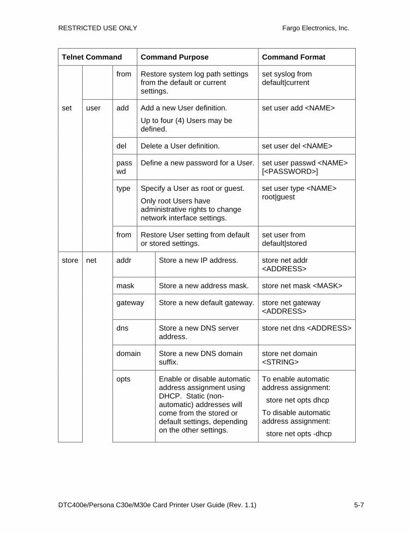
RESTRICTED USE ONLY Fargo Electronics, Inc.
DTC400e/Persona C30e/M30e Card Printer User Guide (Rev. 1.1) 5-7
Telnet Command Command Purpose Command Format
from Restore system log path settings from the default or current settings.
set syslog from default|current
add Add a new User definition.
Up to four (4) Users may be defined.
set user add <NAME>
del Delete a User definition. set user del <NAME>
passwd
Define a new password for a User. set user passwd <NAME> [<PASSWORD>]
type Specify a User as root or guest.
Only root Users have administrative rights to change network interface settings.
set user type <NAME> root|guest
set user
from Restore User setting from default or stored settings.
set user from default|stored
addr Store a new IP address. store net addr <ADDRESS>
mask Store a new address mask. store net mask <MASK>
gateway Store a new default gateway. store net gateway <ADDRESS>
dns Store a new DNS server address.
store net dns <ADDRESS>
domain Store a new DNS domain suffix.
store net domain <STRING>
store net
opts Enable or disable automatic address assignment using DHCP. Static (non-automatic) addresses will come from the stored or default settings, depending on the other settings.
To enable automatic address assignment:
store net opts dhcp
To disable automatic address assignment:
store net opts -dhcp

RESTRICTED USE ONLY Fargo Electronics, Inc.
DTC400e/Persona C30e/M30e Card Printer User Guide (Rev. 1.1) 5-8
Telnet Command Command Purpose Command Format
from Restore the network settings from either the default settings or the current settings.
store net from default|current
mode Specify the Ethernet interface mode as: automatic, full or half duplex; 10 or 100 mHz.
store ifc mode auto|10half|10full|100half|100full
ifc
from Set the Ethernet mode settings from the default or current settings.
store ifc from default|current
save Save all current settings as the stored settings in the permanent memory.
save
load Take the settings from the stored memory and make them the current settings.
load
lpstat Display information about the Printer status.
This includes the status and device response.
See the Printer web page description.
lpstat
cancel Cancel a specific print job from the print queue.
cancel 10
quit Stop the current Telnet session.
quit

RESTRICTED USE ONLY Fargo Electronics, Inc.
DTC400e/Persona C30e/M30e Card Printer User Guide (Rev. 1.1) 5-9
Ethernet Printer Troubleshooting Procedures If you are having trouble connecting to your Ethernet Printer or printing to it, you should go through each of the following procedures.
Step Procedure
1 Follow the Verifying the Printer Connection procedure. See below.
2 Follow the Verifying the Printer IP address procedure.
3 Follow the Verifying that your PC can access the Printer using the ping command procedure.
4 Verify that you are choosing the correct Printer Driver. (Note: The Driver must match the model of the Printer.)
5 Verify that the port configuration of the PC Printer Driver is set to communicate to the Printer over the correct IP address.
See Reviewing Frequently-asked Questions.
6 Follow the Printing a test page procedure.

RESTRICTED USE ONLY Fargo Electronics, Inc.
DTC400e/Persona C30e/M30e Card Printer User Guide (Rev. 1.1) 5-10
Verifying the Printer Connection
Step Procedure
1 Ensure that your Printer has a valid network connection.
3 Verify that the Printer has both LEDs blinking on and off with network activity.
3 If the LEDs do not indicate connection, verify the network connection with another device.
4 If the connection is OK, then something may be wrong with the Ethernet option installation. See the Ethernet Setup and Printer Driver Installation procedure.
Verifying the Printer IP address
Step Procedure
1 Check for a valid IP address (0.0.0.0 in not valid).
• If the IP address is valid, go to step 4 (below).
• If the IP address is not valid, go to step 2 (below).
2 If your network is using DHCP, then:
• Use IP-Tracer to verify that the Printer has not been configured to use a static address.
(Note: This guideline applies unless you have a known, unused static IP address assigned to this Printer.)
3 If you are using a static IP address, then:
• Verify that there is no other device using the same address by removing your Printer and ping to the desired address.
If any device responds, then you must find a different available IP address.
4 If the Printer reports an IP address, then:
• Verify that it matches subnet of the network where it is connected.
If your Printer has DHCP disabled, then:
• The static IP address may have been previously set for a different subnet.

RESTRICTED USE ONLY Fargo Electronics, Inc.
DTC400e/Persona C30e/M30e Card Printer User Guide (Rev. 1.1) 5-11
Verify that the PC can access the Printer using the ping command
Step Procedure
1 Follow these instructions to issue a ping command to the Printer:
At a DOS prompt, enter ping [IP Address] Example: C:\>ping 210.1.10.240
• If the ping response is successful, move on to the next troubleshooting procedure. See Display A below.
• If the ping response is not successful, continue to step 2 of this procedure. See Display B below.
Display A - Example of sending a ping to the Printer with a successful response
Display B - Example of ping timeout to an invalid IP address
2 Verify that the PC and the Printer are connected to the same network.

RESTRICTED USE ONLY Fargo Electronics, Inc.
DTC400e/Persona C30e/M30e Card Printer User Guide (Rev. 1.1) 5-12
3 You may be on different subnets of your network and some of the network settings for the Printer are not correct. See your network administrator about this.
(Note: The subnet mask must be the same as other devices on the network, and that the unique IP address is part of the network specified by the subnet mask.)
Printing a test page
Step Procedure
1 Try printing a test page from the Printer Driver properties window.
a. Open the Printer Driver properties window.
b. Select Start -> Settings -> Printers and Faxes -> [your Printer Driver name (i.e., DTC400e or C30e Card Printer)] -> Properties.
c. Ensure that the printing preferences are set correctly for the Ribbon installed in your Printer.
d. Then select the Print Test page button. See the next section.
2 If you cannot print a test page, then consider the following:
• There may be an error at the Printer.
• There may be a job in the Windows print queue which has stalled.
• The Printer may be paused or set to operate offline in the Windows print queue.

RESTRICTED USE ONLY Fargo Electronics, Inc.
DTC400e/Persona C30e/M30e Card Printer User Guide (Rev. 1.1) 5-13
Reviewing Frequently-asked Questions Question Answer
How do I know if my Printer has the Ethernet option installed?
If your Printer has the RJ45 connector installed on the back of the Printer, then it has this Ethernet option installed.
Can my non-Ethernet-enabled Printer be upgraded to have an Ethernet interface?
No.
What PC operating systems work with my Ethernet Printer?
The Windows 2000/ XP/ Server 2003 operating systems work with your Ethernet Printer.
How do I connect my Printer to my network?
You can connect from the RJ45 network connection on the back of your Printer to an available connection on your network (not directly to your PC).
You can use a good CAT-5 or better cable to make this connection.
How can I find the MAC address of my Ethernet Printer?
If you know the IP address of your Printer, you can access this through the home web page of the Print Server.
OR If you do not know the IP address or the Printer does not work with a usable IP address, then the MAC Address can be found using the IP Tracer tool.
How can I find the IP address of my Ethernet Printer?
See Verifying the Printer IP address.
Can I print from my PC to multiple Ethernet Printers?
Yes. Use the Windows “Add Printer Wizard” to create a new printer instance for the additional printer. This may require adding a new “Remote TCP/IP Card Printer Port” configured to communicate to the new printer at the proper IP address. See the appropriate Windows documentation for additional help.
Can multiple PC’s print to my Ethernet Printer?
Yes. Each PC must have the Printer Driver software installed for the specific Fargo Ethernet-enabled Printer and connect to the intended Printer, using the correct IP address.

RESTRICTED USE ONLY Fargo Electronics, Inc.
DTC400e/Persona C30e/M30e Card Printer User Guide (Rev. 1.1) 5-14
Question Answer
Can I print from my PC to an Ethernet Printer on a different network segment?
Yes. If you know the IP address of the Printer on any segment of your network, you will be able to print to it.
Can I use IP Tracer to locate Printers on a different network segment?
No. The IP Tracer can only locate Printers located in the same network segment (as the PC running IP Tracer).
How do I upgrade the Printer Firmware in my Ethernet-enabled Printer?
This is done in the same manner as a USB connected Printer. The PC doing the upgrade must have a Driver installed for the Fargo Printer to be upgraded.
Follow this procedure.
1. Run the Fargo Workbench Printer Utility from the start menu: Go to the Start -> Programs -> Fargo -> Fargo Workbench Printer Utility -> Fargo Workbench.
2. Select the Fargo Printer to upgrade from the drop-down box.
3. Go to the Firmware Updates tab.
4. If you need to download the update file from the Internet, select the Download Firmware button.
5. Choose the update file with the Select Firmware button.
6. Put your Printer into the upgrade mode. See the instructions for your specific Fargo Printer.
7. Select the Send Firmware button.
What is the default User name and password for the Printer?
The default passwords are blank (i.e., an empty string).
• The default Users are as follows: root as the administrative User and guest as a non-administrative User.
• The Printer supports four (4) Users.
What if I lose the password for my Printer or it is not accepted?
Factory default settings will be restored to the Printer if power is applied to the Printer with Dipswitch 1 in the ON position and Dipswitch 2 in the OFF position.
(Note: This will reset all Print Server settings, which includes static network settings, user configurations and user passwords.)
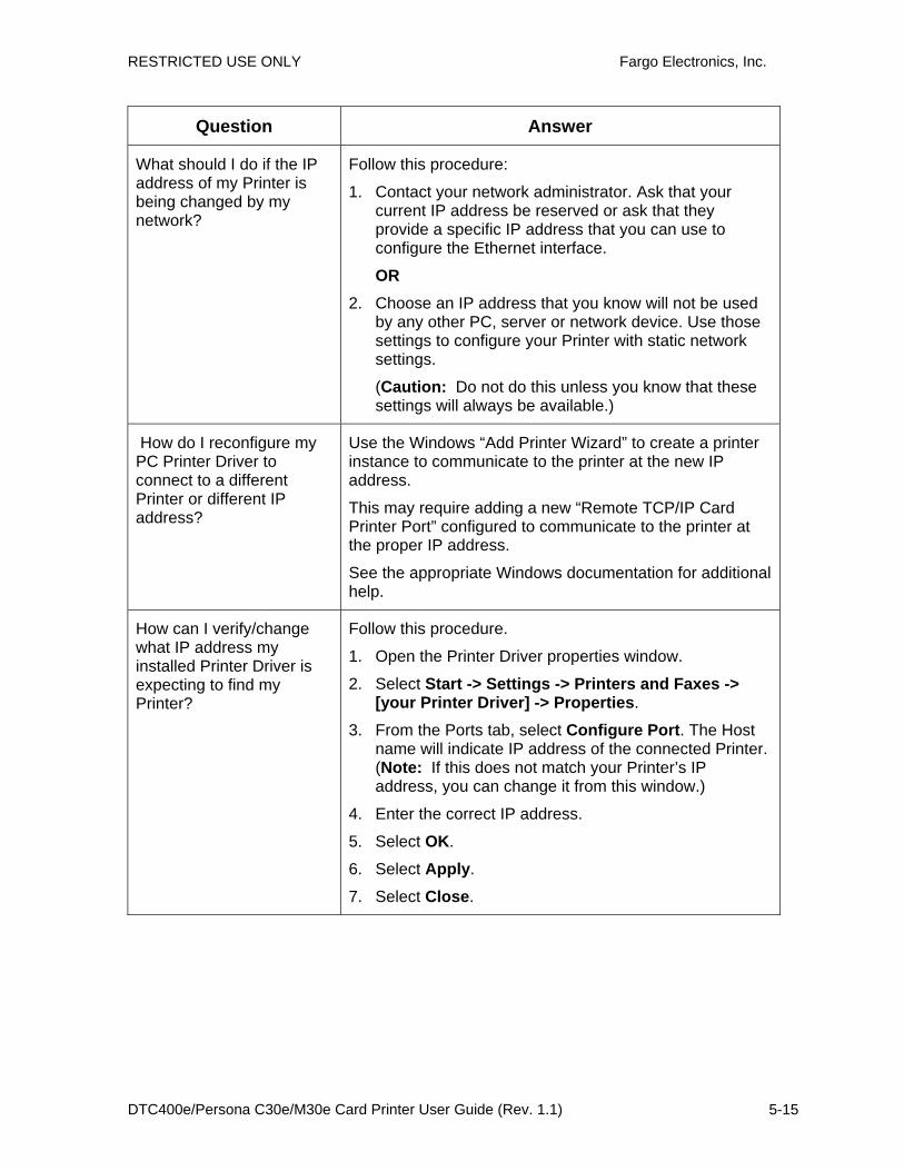
RESTRICTED USE ONLY Fargo Electronics, Inc.
DTC400e/Persona C30e/M30e Card Printer User Guide (Rev. 1.1) 5-15
Question Answer
What should I do if the IP address of my Printer is being changed by my network?
Follow this procedure:
1. Contact your network administrator. Ask that your current IP address be reserved or ask that they provide a specific IP address that you can use to configure the Ethernet interface.
OR 2. Choose an IP address that you know will not be used
by any other PC, server or network device. Use those settings to configure your Printer with static network settings.
(Caution: Do not do this unless you know that these settings will always be available.)
How do I reconfigure my PC Printer Driver to connect to a different Printer or different IP address?
Use the Windows “Add Printer Wizard” to create a printer instance to communicate to the printer at the new IP address.
This may require adding a new “Remote TCP/IP Card Printer Port” configured to communicate to the printer at the proper IP address.
See the appropriate Windows documentation for additional help.
How can I verify/change what IP address my installed Printer Driver is expecting to find my Printer?
Follow this procedure.
1. Open the Printer Driver properties window.
2. Select Start -> Settings -> Printers and Faxes -> [your Printer Driver] -> Properties.
3. From the Ports tab, select Configure Port. The Host name will indicate IP address of the connected Printer. (Note: If this does not match your Printer’s IP address, you can change it from this window.)
4. Enter the correct IP address.
5. Select OK.
6. Select Apply.
7. Select Close.
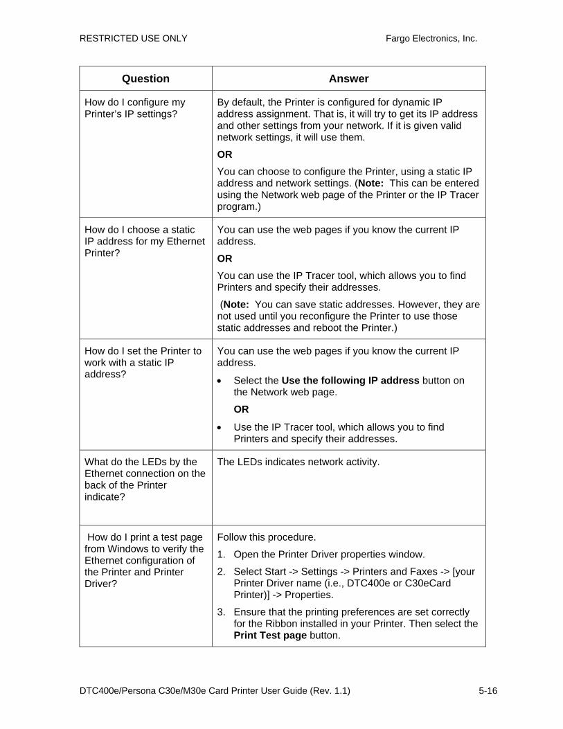
RESTRICTED USE ONLY Fargo Electronics, Inc.
DTC400e/Persona C30e/M30e Card Printer User Guide (Rev. 1.1) 5-16
Question Answer
How do I configure my Printer’s IP settings?
By default, the Printer is configured for dynamic IP address assignment. That is, it will try to get its IP address and other settings from your network. If it is given valid network settings, it will use them.
OR You can choose to configure the Printer, using a static IP address and network settings. (Note: This can be entered using the Network web page of the Printer or the IP Tracer program.)
How do I choose a static IP address for my Ethernet Printer?
You can use the web pages if you know the current IP address.
OR You can use the IP Tracer tool, which allows you to find Printers and specify their addresses.
(Note: You can save static addresses. However, they are not used until you reconfigure the Printer to use those static addresses and reboot the Printer.)
How do I set the Printer to work with a static IP address?
You can use the web pages if you know the current IP address.
• Select the Use the following IP address button on the Network web page.
OR
• Use the IP Tracer tool, which allows you to find Printers and specify their addresses.
What do the LEDs by the Ethernet connection on the back of the Printer indicate?
The LEDs indicates network activity.
How do I print a test page from Windows to verify the Ethernet configuration of the Printer and Printer Driver?
Follow this procedure.
1. Open the Printer Driver properties window.
2. Select Start -> Settings -> Printers and Faxes -> [your Printer Driver name (i.e., DTC400e or C30eCard Printer)] -> Properties.
3. Ensure that the printing preferences are set correctly for the Ribbon installed in your Printer. Then select the Print Test page button.
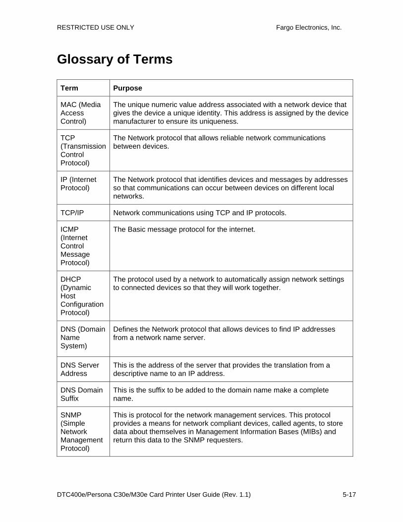
RESTRICTED USE ONLY Fargo Electronics, Inc.
DTC400e/Persona C30e/M30e Card Printer User Guide (Rev. 1.1) 5-17
Glossary of Terms Term Purpose
MAC (Media Access Control)
The unique numeric value address associated with a network device that gives the device a unique identity. This address is assigned by the device manufacturer to ensure its uniqueness.
TCP (Transmission Control Protocol)
The Network protocol that allows reliable network communications between devices.
IP (Internet Protocol)
The Network protocol that identifies devices and messages by addresses so that communications can occur between devices on different local networks.
TCP/IP Network communications using TCP and IP protocols.
ICMP (Internet Control Message Protocol)
The Basic message protocol for the internet.
DHCP (Dynamic Host Configuration Protocol)
The protocol used by a network to automatically assign network settings to connected devices so that they will work together.
DNS (Domain Name System)
Defines the Network protocol that allows devices to find IP addresses from a network name server.
DNS Server Address
This is the address of the server that provides the translation from a descriptive name to an IP address.
DNS Domain Suffix
This is the suffix to be added to the domain name make a complete name.
SNMP (Simple Network Management Protocol)
This is protocol for the network management services. This protocol provides a means for network compliant devices, called agents, to store data about themselves in Management Information Bases (MIBs) and return this data to the SNMP requesters.
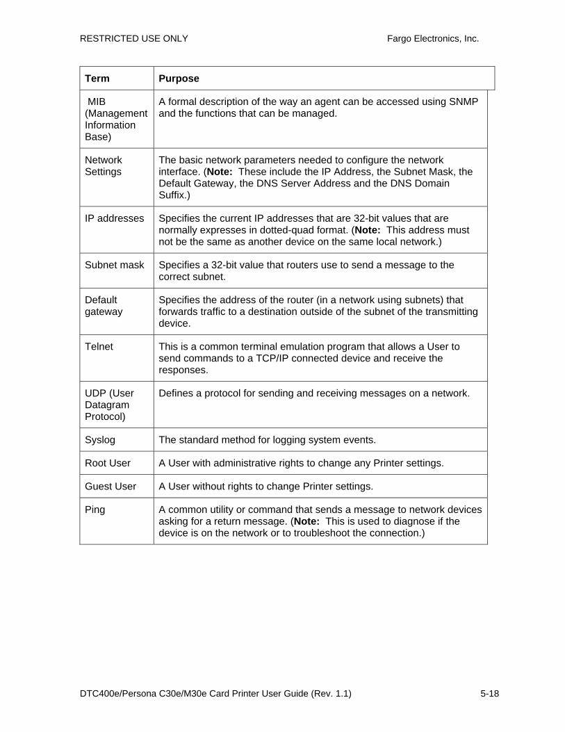
RESTRICTED USE ONLY Fargo Electronics, Inc.
DTC400e/Persona C30e/M30e Card Printer User Guide (Rev. 1.1) 5-18
Term Purpose
MIB (Management Information Base)
A formal description of the way an agent can be accessed using SNMP and the functions that can be managed.
Network Settings
The basic network parameters needed to configure the network interface. (Note: These include the IP Address, the Subnet Mask, the Default Gateway, the DNS Server Address and the DNS Domain Suffix.)
IP addresses Specifies the current IP addresses that are 32-bit values that are normally expresses in dotted-quad format. (Note: This address must not be the same as another device on the same local network.)
Subnet mask Specifies a 32-bit value that routers use to send a message to the correct subnet.
Default gateway
Specifies the address of the router (in a network using subnets) that forwards traffic to a destination outside of the subnet of the transmitting device.
Telnet This is a common terminal emulation program that allows a User to send commands to a TCP/IP connected device and receive the responses.
UDP (User Datagram Protocol)
Defines a protocol for sending and receiving messages on a network.
Syslog The standard method for logging system events.
Root User A User with administrative rights to change any Printer settings.
Guest User A User without rights to change Printer settings.
Ping A common utility or command that sends a message to network devices asking for a return message. (Note: This is used to diagnose if the device is on the network or to troubleshoot the connection.)
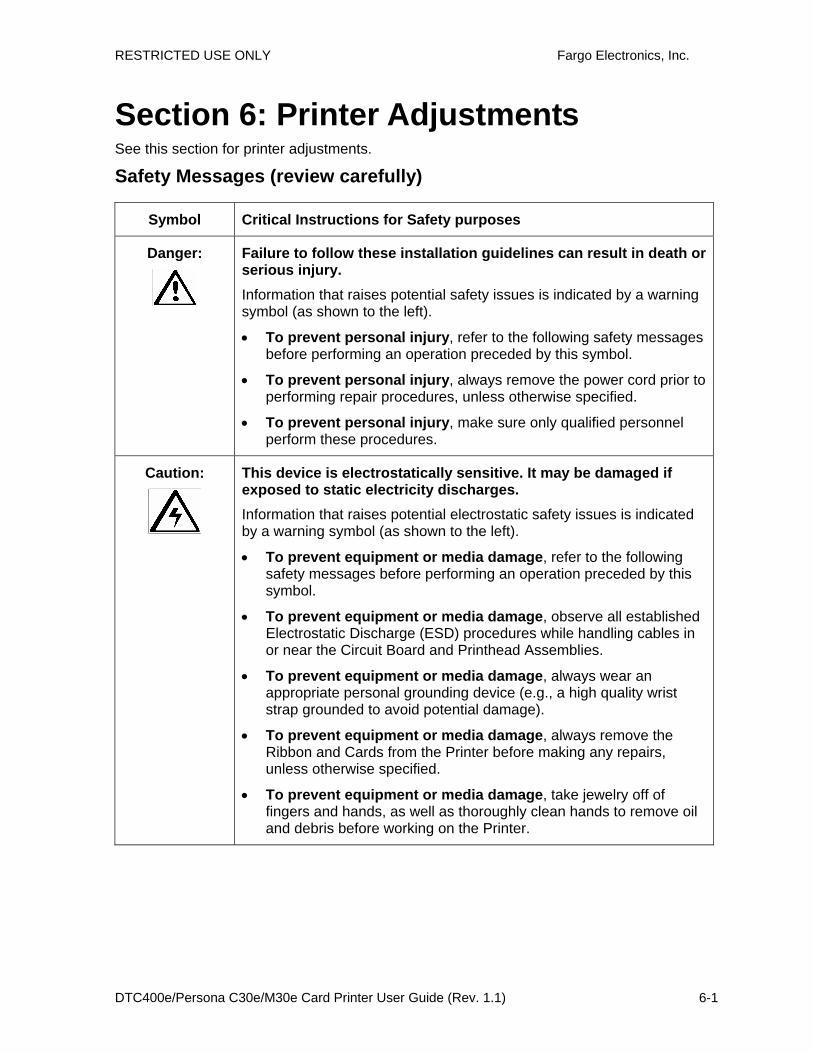
RESTRICTED USE ONLY Fargo Electronics, Inc.
DTC400e/Persona C30e/M30e Card Printer User Guide (Rev. 1.1) 6-1
Section 6: Printer Adjustments See this section for printer adjustments.
Safety Messages (review carefully)
Symbol Critical Instructions for Safety purposes
Danger:
Failure to follow these installation guidelines can result in death or serious injury. Information that raises potential safety issues is indicated by a warning symbol (as shown to the left).
• To prevent personal injury, refer to the following safety messages before performing an operation preceded by this symbol.
• To prevent personal injury, always remove the power cord prior to performing repair procedures, unless otherwise specified.
• To prevent personal injury, make sure only qualified personnel perform these procedures.
Caution:
This device is electrostatically sensitive. It may be damaged if exposed to static electricity discharges. Information that raises potential electrostatic safety issues is indicated by a warning symbol (as shown to the left).
• To prevent equipment or media damage, refer to the following safety messages before performing an operation preceded by this symbol.
• To prevent equipment or media damage, observe all established Electrostatic Discharge (ESD) procedures while handling cables in or near the Circuit Board and Printhead Assemblies.
• To prevent equipment or media damage, always wear an appropriate personal grounding device (e.g., a high quality wrist strap grounded to avoid potential damage).
• To prevent equipment or media damage, always remove the Ribbon and Cards from the Printer before making any repairs, unless otherwise specified.
• To prevent equipment or media damage, take jewelry off of fingers and hands, as well as thoroughly clean hands to remove oil and debris before working on the Printer.
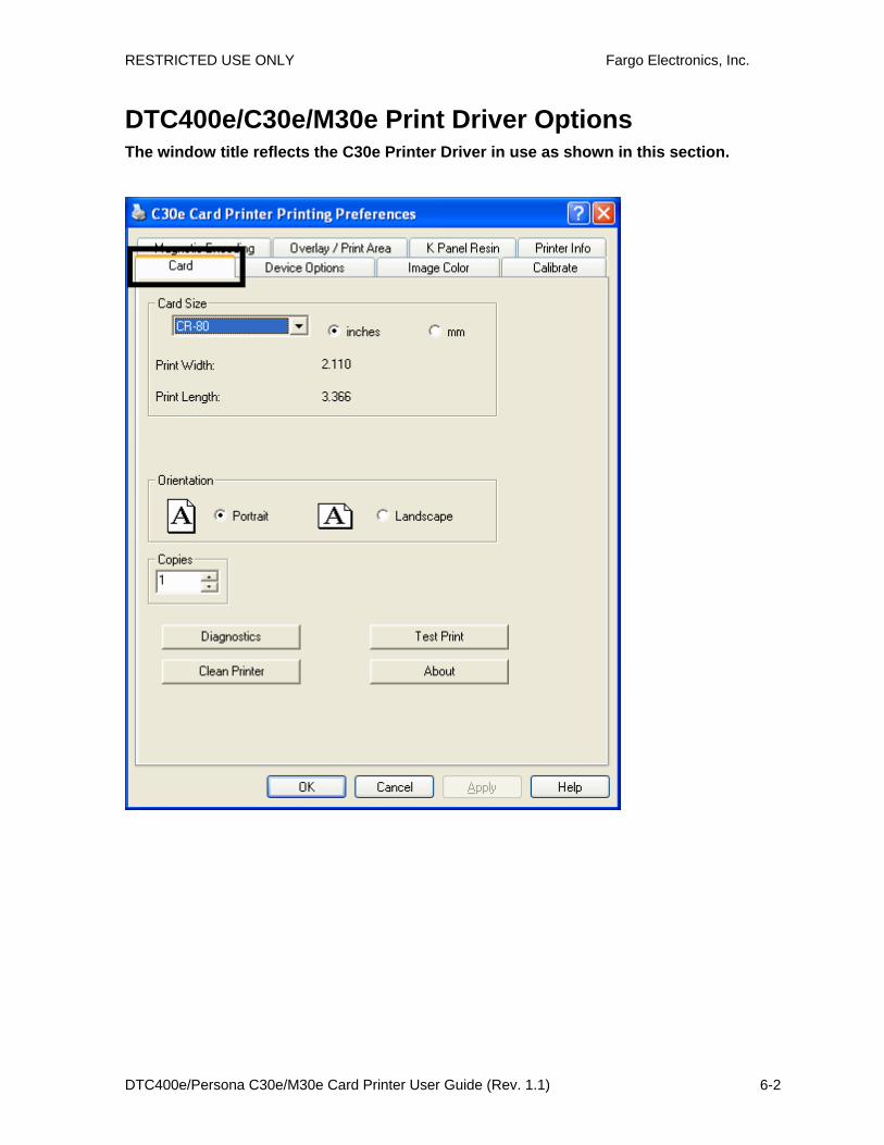
RESTRICTED USE ONLY Fargo Electronics, Inc.
DTC400e/Persona C30e/M30e Card Printer User Guide (Rev. 1.1) 6-2
DTC400e/C30e/M30e Print Driver Options The window title reflects the C30e Printer Driver in use as shown in this section.

RESTRICTED USE ONLY Fargo Electronics, Inc.
DTC400e/Persona C30e/M30e Card Printer User Guide (Rev. 1.1) 6-3
Using the Card tab (DTC400e/C30e/M30e) Adjusting the Card Size Option
Step Description
1 Click inches or mm to choose the desired unit of measurement.
(Note No.1: When designing a card format, always set the card size or page size within the card design program to the exact dimensions of a CR-79 or CR-80 card.)
(Note No.2: The Card Size indicates that the Printer accepts standard, credit card size CR-80 (ISO ID-1) cards or CR-79 sized cards. The dimensions of the total print area for this card size appear in the Print Width: and Print Length: areas, as shown below.)

RESTRICTED USE ONLY Fargo Electronics, Inc.
DTC400e/Persona C30e/M30e Card Printer User Guide (Rev. 1.1) 6-4
Adjusting the Orientation Option
Step Description
1 Select Portrait to cause the card to print in a vertical orientation.
OR Select Landscape to cause the card to print in a horizontal orientation.
(Note: An icon illustrating a printed card helps represent the difference between the two.)

RESTRICTED USE ONLY Fargo Electronics, Inc.
DTC400e/Persona C30e/M30e Card Printer User Guide (Rev. 1.1) 6-5
Selecting the number of copies
Step Description
1 Select the number of copies by clicking on the UP or DOWN arrows, as shown below.

RESTRICTED USE ONLY Fargo Electronics, Inc.
DTC400e/Persona C30e/M30e Card Printer User Guide (Rev. 1.1) 6-6
Using the Diagnostics button under the Card tab
Step Description
1 Click Diagnostics to bring up the Fargo Workbench Printer Utility window.

RESTRICTED USE ONLY Fargo Electronics, Inc.
DTC400e/Persona C30e/M30e Card Printer User Guide (Rev. 1.1) 6-7
Using the Clean Printer Option
Step Description
1 Click Clean Printer to display the Clean Printer Utility window.
2 Remove all cards from the Card Hopper and close the Hopper door.
3 Open the Front Cover and remove the Ribbon Cartridge.
4 Remove the paper backing from both sides of the Cleaning Card.
5 Place the Cleaning card into the Single Feed Slot.

RESTRICTED USE ONLY Fargo Electronics, Inc.
DTC400e/Persona C30e/M30e Card Printer User Guide (Rev. 1.1) 6-8
6 Click Clean. (Note: The Printer will begin to feed the cleaning card through the card path.)
7 Reinsert the print Ribbon and cards after the cleaning procedure has completed.

RESTRICTED USE ONLY Fargo Electronics, Inc.
DTC400e/Persona C30e/M30e Card Printer User Guide (Rev. 1.1) 6-9
Using the Test Print button
Step Description
1 Click Test Print to send a simple self-test print to the DTC400e or C30e Printer.
• Ensure that an YMCKO Ribbon is installed.
• Ensure that the computer is effectively communicating with the Printer and that the Printer is functioning properly.
• Ensure that an YMCKOK Ribbon is installed in order for a DTC400e/C30e Card Printer with a Flipper Table Module to print a dual-sided image.
2 Click Test Print to send a simple self-test print to the M30e Printer.
• Ensure that the Ribbon is installed for M30e
• Ensure that the computer is effectively communicating with the Printer and that the Printer is functioning properly.
Ensure that the Ribbon is installed in order for a M30e Card Printer with a Flipper Table Module to print a dual-sided image.

RESTRICTED USE ONLY Fargo Electronics, Inc.
DTC400e/Persona C30e/M30e Card Printer User Guide (Rev. 1.1) 6-10
Using the About button
Step Description
1 Click About to open a dialog box containing the copyright and version, date code information about this Printer Driver software.

RESTRICTED USE ONLY Fargo Electronics, Inc.
DTC400e/Persona C30e/M30e Card Printer User Guide (Rev. 1.1) 6-11
Using the Device Options tab (DTC400e/C30e or M30e)
The DTC400e/C30e window with the Device Options tab is displayed below.
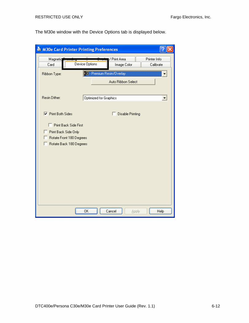
RESTRICTED USE ONLY Fargo Electronics, Inc.
DTC400e/Persona C30e/M30e Card Printer User Guide (Rev. 1.1) 6-12
The M30e window with the Device Options tab is displayed below.
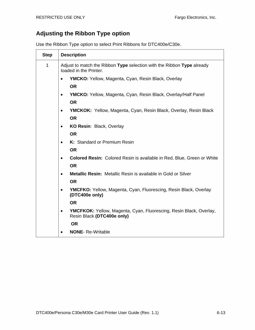
RESTRICTED USE ONLY Fargo Electronics, Inc.
DTC400e/Persona C30e/M30e Card Printer User Guide (Rev. 1.1) 6-13
Adjusting the Ribbon Type option
Use the Ribbon Type option to select Print Ribbons for DTC400e/C30e.
Step Description
1 Adjust to match the Ribbon Type selection with the Ribbon Type already loaded in the Printer.
• YMCKO: Yellow, Magenta, Cyan, Resin Black, Overlay
OR
• YMCKO: Yellow, Magenta, Cyan, Resin Black, Overlay/Half Panel
OR
• YMCKOK: Yellow, Magenta, Cyan, Resin Black, Overlay, Resin Black
OR
• KO Resin: Black, Overlay
OR
• K: Standard or Premium Resin
OR
• Colored Resin: Colored Resin is available in Red, Blue, Green or White
OR
• Metallic Resin: Metallic Resin is available in Gold or Silver
OR
• YMCFKO: Yellow, Magenta, Cyan, Fluorescing, Resin Black, Overlay (DTC400e only) OR
• YMCFKOK: Yellow, Magenta, Cyan, Fluorescing, Resin Black, Overlay, Resin Black (DTC400e only)
OR
• NONE- Re-Writable

RESTRICTED USE ONLY Fargo Electronics, Inc.
DTC400e/Persona C30e/M30e Card Printer User Guide (Rev. 1.1) 6-14

RESTRICTED USE ONLY Fargo Electronics, Inc.
DTC400e/Persona C30e/M30e Card Printer User Guide (Rev. 1.1) 6-15
Use the Ribbon Type option to select Print Ribbons for the M30e.
Step Description
1 Select the appropriate Ribbon for the type of Print Ribbon in use.
• K – Standard Resin
• K – Premium Resin
• Colored Resin
• Metallic Resin
• KO – Premium Resin/Overlay
• BO – Dye-sub Black/Overlay

RESTRICTED USE ONLY Fargo Electronics, Inc.
DTC400e/Persona C30e/M30e Card Printer User Guide (Rev. 1.1) 6-16
Selecting the Auto Ribbon Select option
Step Description
1 Click Auto Ribbon Select to verify that the Ribbon type selected matches the Ribbon installed in the Printer. (Note: The Printer Driver will change the Ribbon type to the correct setting or validate. It will also display a dialog that it has changed the current setting or that the current Ribbon type is correct.)
2 Click Test Print to send a simple self-test print to the DTC400e/C30ePrinter.
• Ensure that an YMCKO Ribbon is installed.
• Ensure that the computer is effectively communicating with the Printer and that the Printer is functioning properly.
Ensure that an YMCKOK Ribbon is installed in order for a DTC400e/C30e Card Printer with a Flipper Table Module to print a dual-sided image.

RESTRICTED USE ONLY Fargo Electronics, Inc.
DTC400e/Persona C30e/M30e Card Printer User Guide (Rev. 1.1) 6-17
3 Click Test Print to send a simple self-test print to the M30e Printer.
• Ensure that the Premium Resin Ribbon is installed for M30e
• Ensure that the computer is effectively communicating with the Printer and that the Printer is functioning properly.

RESTRICTED USE ONLY Fargo Electronics, Inc.
DTC400e/Persona C30e/M30e Card Printer User Guide (Rev. 1.1) 6-18
Changing the Color Profile Selection for the DTC400e/C30e
Step Procedure
1 a. From your computer’s startup menu, select Settings > Printers and Faxes (Windows XP) or Settings > Printers (Windows 2000).
b. Double click on the DTC400e/C30e Card Printer under the Printers window.
c. Select Properties under the Printer drop-down menu. (Note: This will bring up the DTC400e/C30e Card Printer Properties window, as shown on the next page.)
2 Click the Color Management tab.
3 Click Manual.
4 Click DTC400e/C30e CLR_E for improved color matching. (Note: This color profile has better screen to printer matching.) OR
Click DTC400e/C30e CLR_O if you already have an existing base of cards using this color profile, and you want to maintain the same color matching.
(Note: If the DTC400e/C30e CLR_O color profile is not listed, it can be added by clicking Add and browsing to Program Files\Fargo\Printer Driver Software\ DTC400e/C30e Driver Files and selecting DTC400e/C30e CLR_O.icm.)
5 Click Set as Default.

RESTRICTED USE ONLY Fargo Electronics, Inc.
DTC400e/Persona C30e/M30e Card Printer User Guide (Rev. 1.1) 6-19

RESTRICTED USE ONLY Fargo Electronics, Inc.
DTC400e/Persona C30e/M30e Card Printer User Guide (Rev. 1.1) 6-20
Adjusting the Color Matching option
Use the Color Matching dropdown menu to choose the color matching options which best fits the print job requirements.
Step Description
1 Select None for print speed versus print color or for use of third party color matching software.
OR Select Algebraic (a) for the Printer Driver to make very simple, yet fast, color balance adjustments; (b) for more natural looking images without actually utilizing any specific color matching; or (c) for customized, printed coloring of the cards through the Image Color tab.
OR Select Monitor for the Printer Driver to make color corrections similar to the Algebraic option but through a more complex color matching algorithm.
OR Select System Color Management for Windows to make color corrections. This provides a closer match to the sRGB color specifications. (Note: This option shifts colors to a different color model so the colors in the image will more closely match how they appear on the monitor.)

RESTRICTED USE ONLY Fargo Electronics, Inc.
DTC400e/Persona C30e/M30e Card Printer User Guide (Rev. 1.1) 6-21
Adjusting for the Resin Dither
Select the appropriate dither method according to the type of image to be printed. This option affects objects printed with a resin-only print Ribbon.
Step Procedure
1 Select Optimized for Photo when printing photo quality images with resin.
OR Select Optimized for Graphics when printing drawings and graphics (e.g., clipart, logos, etc.) with resin.

RESTRICTED USE ONLY Fargo Electronics, Inc.
DTC400e/Persona C30e/M30e Card Printer User Guide (Rev. 1.1) 6-22
Using the Print Both Sides option
Use this option to automatically print on both the front and back of a card.
Step Procedure
1 Select this option in conjunction with any application program that supports a multiple-page document with duplex printing. (Note: The program must be able to send down two or more separate pages to be printed within the same document.)
2 • Page 1 will be transferred to the front side of the card.
• Page 2 will be transferred to the backside of the card.
(Note: The Printer Driver will always place all odd numbered pages on the front side of the card and all even numbered pages on the back side with this option selected. If an odd number of pages are printed to the Driver while this option is selected, then the Printer will print an additional blank side, and transfer it to the card.)

RESTRICTED USE ONLY Fargo Electronics, Inc.
DTC400e/Persona C30e/M30e Card Printer User Guide (Rev. 1.1) 6-23
Using the Split 1 Set of Ribbon Panels option
Use this option to provide the most economical means of printing a dual-sided card since a single set of Ribbon Panels will be split to print both the front and backsides of a card.
Step Procedure
1 Select this option to automatically print full-color on the front of a card and resin black on the back of a card (using either of the Full-color YMCKO or YMCKOK Print Ribbons).
• If using the YMCKO Ribbon type, the front of the card is printed with the Ribbon's YMC Panels and the back is printed with the K Panel, and the O Panel is printed on the front.
• If using the YMCKOK Ribbon type, the front of the card is printed with the YMCKO Panels and the back is printed with the second K Panel.
(Note #1: This option is automatically enabled when the YMCKOK Ribbon type is selected.)

RESTRICTED USE ONLY Fargo Electronics, Inc.
DTC400e/Persona C30e/M30e Card Printer User Guide (Rev. 1.1) 6-24
Using the Print Back Side First option
Step Procedure
1 Select this option:
• If you need to print the first page of a two-page document on the backside of the card.
OR
• If you need to print the resin black on the chip-side of the Smartcard.
The second page of the document will be printed on the front side of the card.
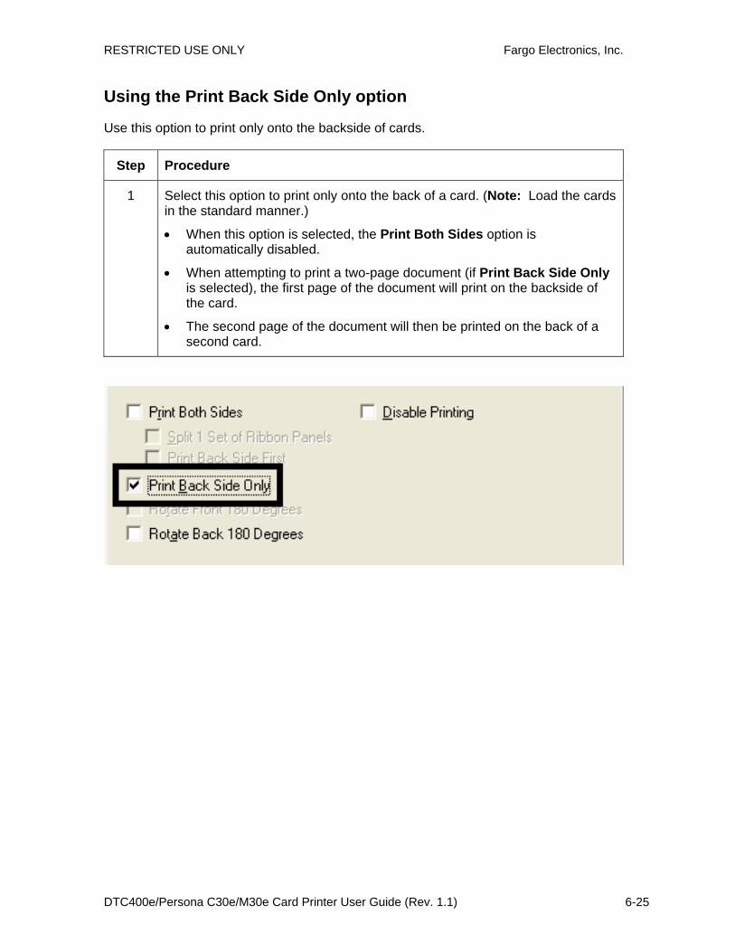
RESTRICTED USE ONLY Fargo Electronics, Inc.
DTC400e/Persona C30e/M30e Card Printer User Guide (Rev. 1.1) 6-25
Using the Print Back Side Only option
Use this option to print only onto the backside of cards.
Step Procedure
1 Select this option to print only onto the back of a card. (Note: Load the cards in the standard manner.)
• When this option is selected, the Print Both Sides option is automatically disabled.
• When attempting to print a two-page document (if Print Back Side Only is selected), the first page of the document will print on the backside of the card.
• The second page of the document will then be printed on the back of a second card.

RESTRICTED USE ONLY Fargo Electronics, Inc.
DTC400e/Persona C30e/M30e Card Printer User Guide (Rev. 1.1) 6-26
Using the Rotate Front 180 Degrees or Rotate Back 180 Degrees options
Use this option to change the position of the printed image in relation to the location of a card's Magnetic Stripe or smart chip.
Step Procedure
1 Select Rotate Front 180 Degrees to rotate the image on the front of the card by 180 degrees when printed.
OR Select the Rotate Back 180 Degrees to rotate the image on the back of the card by 180 degrees when printed.

RESTRICTED USE ONLY Fargo Electronics, Inc.
DTC400e/Persona C30e/M30e Card Printer User Guide (Rev. 1.1) 6-27
Using the Disable Printing option
Use this option to disable the printing capabilities of the Printer. (Note: This option still allows the Printer to encode cards.)
Step Description
1 Select Disable Printing to encode or re-encode cards to save time and avoid the use of printing supplies. (Note: When this option is selected, no print data will be sent to the Printer. All encoding instructions will be sent according to how they are configured within the software.)

RESTRICTED USE ONLY Fargo Electronics, Inc.
DTC400e/Persona C30e/M30e Card Printer User Guide (Rev. 1.1) 6-28
Using the Image Color tab (DTC400e/C30e/M30e)
Step Procedure
1 Select Algebraic and then use this option to control the Contrast and Gamma of the printed image, as well as the individual color balance of Yellow, Magenta and Cyan. (Note: In most cases, the default settings of these options will suffice.)
2 Control the overall darkness and lightness of the printed image by adjusting the Dye-Sub Intensity slider.
• Move the slide to the left to cause less heat to be used in the printing process, thus generating a lighter print.
• Move the slide to the right to cause more heat to be used, thus generating a darker print. (Note: This slide only affects those images printed with dye-sublimation Ribbon panels (YMC).)
C30e
M30e

RESTRICTED USE ONLY Fargo Electronics, Inc.
DTC400e/Persona C30e/M30e Card Printer User Guide (Rev. 1.1) 6-29
Using the Resin Heat (K) option (Front and Back) Use this option to control the amount of heat the Printer uses when printing with the resin black panel(s) of a full-color Ribbon or when printing with a resin-only Ribbon by adjusting the Resin Heat slide.
Step Procedure
1 Adjust the Resin Heat, Front (K) or the Resin Head, Back (K) as needed.
• Move the slide to the left to cause less heat to be used in the printing process, causing resin images to be lighter or less saturated.
OR
• Move the slide to the right to (a) cause more heat to be used or (b) cause the resin image to be darker or more saturated.
(Note: This control can be helpful for fine-tuning the transfer of resin text and bar codes.)
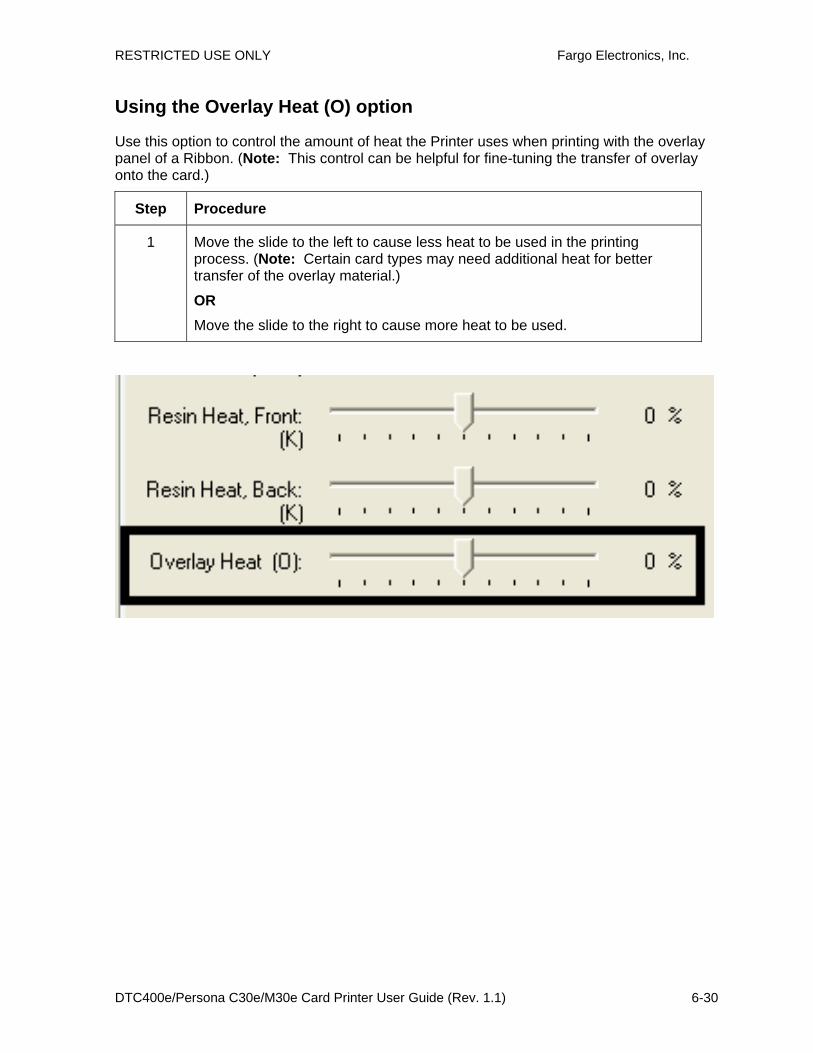
RESTRICTED USE ONLY Fargo Electronics, Inc.
DTC400e/Persona C30e/M30e Card Printer User Guide (Rev. 1.1) 6-30
Using the Overlay Heat (O) option
Use this option to control the amount of heat the Printer uses when printing with the overlay panel of a Ribbon. (Note: This control can be helpful for fine-tuning the transfer of overlay onto the card.)
Step Procedure
1 Move the slide to the left to cause less heat to be used in the printing process. (Note: Certain card types may need additional heat for better transfer of the overlay material.)
OR Move the slide to the right to cause more heat to be used.

RESTRICTED USE ONLY Fargo Electronics, Inc.
DTC400e/Persona C30e/M30e Card Printer User Guide (Rev. 1.1) 6-31
Using the Color Matching option and Default button
Step Procedure
1 To return all options to their factory settings, click Default.
DTDC400e/C30e
M30e

RESTRICTED USE ONLY Fargo Electronics, Inc.
DTC400e/Persona C30e/M30e Card Printer User Guide (Rev. 1.1) 6-32
Using the Calibrate tab (DTC400e/C30e/M30e) Use the Calibrate tab to (a) control the position of the printable area in relation to the card, (b) calibrate Sensors and (c) adjust the internal Printer settings that are customized for every Printer and saved directly within the Printer's memory.

RESTRICTED USE ONLY Fargo Electronics, Inc.
DTC400e/Persona C30e/M30e Card Printer User Guide (Rev. 1.1) 6-33
Using the Image Position Controls
Use the Image Position controls to adjust the position of the overall print area to be precisely centered on a card.
Step Procedure
1 Click the Vertical and Horizontal adjustment arrows to adjust the Image Position values.
• When adjusting these values, keep in mind that the card always remain in the same position while moving through the Printer, regardless of image orientation.
• To illustrate this, the card illustration shown in the Image Position box will flip and rotate according to the Portrait, Landscape or Rotate 180 Degrees selection.
• The outline around the illustration will always remain in the same Landscape orientation.
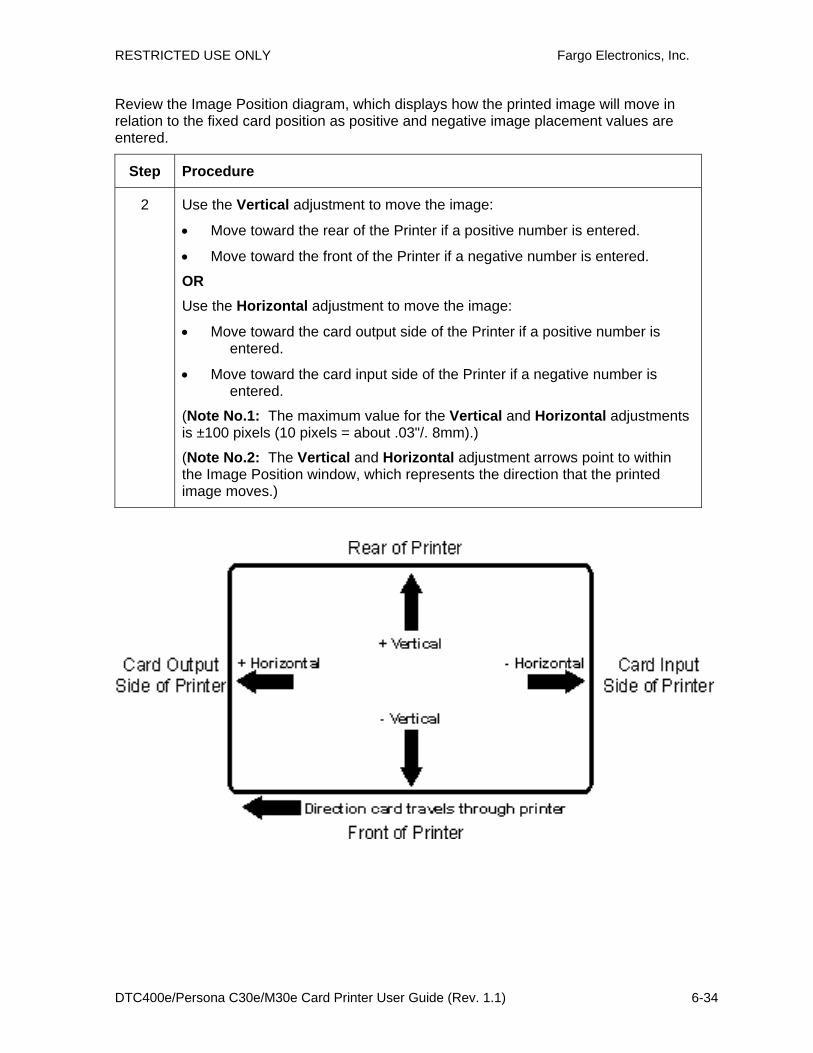
RESTRICTED USE ONLY Fargo Electronics, Inc.
DTC400e/Persona C30e/M30e Card Printer User Guide (Rev. 1.1) 6-34
Review the Image Position diagram, which displays how the printed image will move in relation to the fixed card position as positive and negative image placement values are entered.
Step Procedure
2 Use the Vertical adjustment to move the image:
• Move toward the rear of the Printer if a positive number is entered.
• Move toward the front of the Printer if a negative number is entered.
OR Use the Horizontal adjustment to move the image:
• Move toward the card output side of the Printer if a positive number is entered.
• Move toward the card input side of the Printer if a negative number is entered.
(Note No.1: The maximum value for the Vertical and Horizontal adjustments is ±100 pixels (10 pixels = about .03"/. 8mm).)
(Note No.2: The Vertical and Horizontal adjustment arrows point to within the Image Position window, which represents the direction that the printed image moves.)
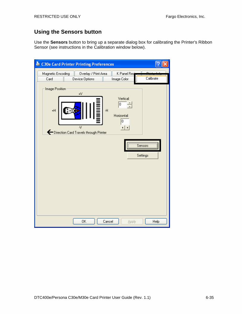
RESTRICTED USE ONLY Fargo Electronics, Inc.
DTC400e/Persona C30e/M30e Card Printer User Guide (Rev. 1.1) 6-35
Using the Sensors button
Use the Sensors button to bring up a separate dialog box for calibrating the Printer's Ribbon Sensor (see instructions in the Calibration window below).
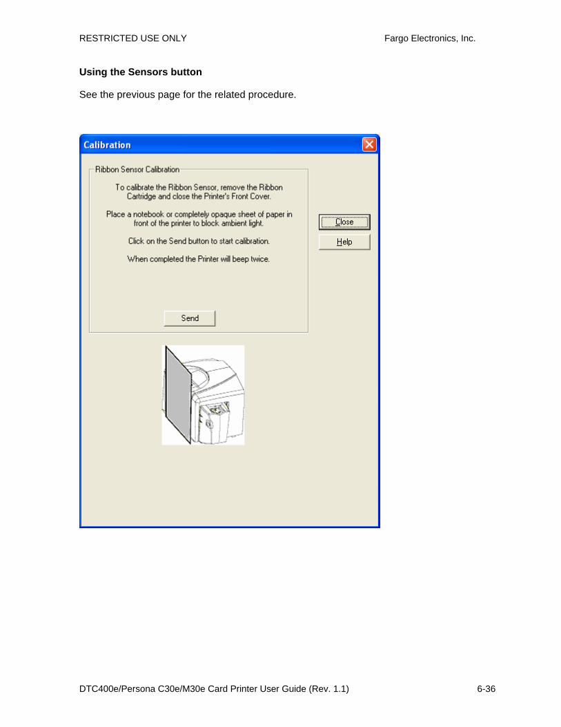
RESTRICTED USE ONLY Fargo Electronics, Inc.
DTC400e/Persona C30e/M30e Card Printer User Guide (Rev. 1.1) 6-36
Using the Sensors button
See the previous page for the related procedure.

RESTRICTED USE ONLY Fargo Electronics, Inc.
DTC400e/Persona C30e/M30e Card Printer User Guide (Rev. 1.1) 6-37
Using the Settings button
Use the Settings button to bring up a dialog for adjusting the internal Printer settings, which are customized for every Printer at the factory and saved directly within the Printer's memory. (Note: You can select the Restore Defaults to restore the internal default settings.)

RESTRICTED USE ONLY Fargo Electronics, Inc.
DTC400e/Persona C30e/M30e Card Printer User Guide (Rev. 1.1) 6-38
Using the Magnetic Encoding tab Use these options only if the Printer has an optional Magnetic Stripe Encoding Module installed.
Step Procedure
1 Select the Magnetic Encoding tab to display options for controlling the Magnetic Stripe encoding process. (Note: The following describes these options and the Printer's magnetic encoding process.)

RESTRICTED USE ONLY Fargo Electronics, Inc.
DTC400e/Persona C30e/M30e Card Printer User Guide (Rev. 1.1) 6-39
Using the Encoding Mode dropdown list
You can use the Encoding Mode option in order to specify which magnetic encoding standard to use.
Category Description
Installation The DTC400e/C30e/M30e Card Printer can be installed with one of two types of factory installed Magnetic Stripe Encoding Modules.
Magnetic Encoding options (changing and modifying)
Change the encoding mode and coercivity setting or modify the ISO standards for Tracks 1, 2 and 3. This can be done by correctly modifying these Magnetic Encoding options.

RESTRICTED USE ONLY Fargo Electronics, Inc.
DTC400e/Persona C30e/M30e Card Printer User Guide (Rev. 1.1) 6-40
ISO Encoding selection (active and inactive functions)
If you select ISO Encoding, you send down a formatted set of characters. (Note: This selection activates the track tabs. However, all functions on the Track tabs are inactive or gray and display ISO defaults, which are the defaults listed for each track below. The Shift Data Left check box remains unchecked and inactive.)

RESTRICTED USE ONLY Fargo Electronics, Inc.
DTC400e/Persona C30e/M30e Card Printer User Guide (Rev. 1.1) 6-41
Custom Encoding selection (active and inactive functions)
If you select Custom Encoding, all options are active. The Default is ISO Encoding. (Note: The defaults are the same as the ISO Encoding defaults. However, all functions on the Magnetic Track Options tabs are active.)
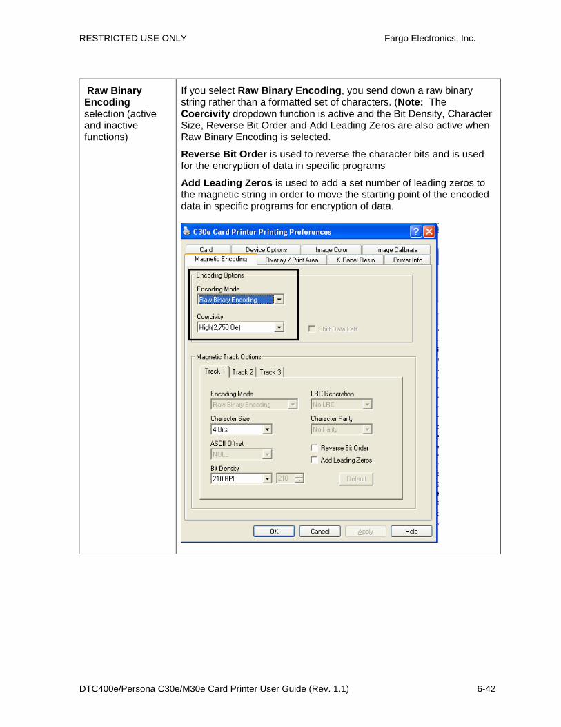
RESTRICTED USE ONLY Fargo Electronics, Inc.
DTC400e/Persona C30e/M30e Card Printer User Guide (Rev. 1.1) 6-42
Raw Binary Encoding selection (active and inactive functions)
If you select Raw Binary Encoding, you send down a raw binary string rather than a formatted set of characters. (Note: The Coercivity dropdown function is active and the Bit Density, Character Size, Reverse Bit Order and Add Leading Zeros are also active when Raw Binary Encoding is selected.
Reverse Bit Order is used to reverse the character bits and is used for the encryption of data in specific programs
Add Leading Zeros is used to add a set number of leading zeros to the magnetic string in order to move the starting point of the encoded data in specific programs for encryption of data.

RESTRICTED USE ONLY Fargo Electronics, Inc.
DTC400e/Persona C30e/M30e Card Printer User Guide (Rev. 1.1) 6-43
Raw Binary Encoding selection (continued from the previous page)
Raw Magnetic Encoding The User can select Raw Magnetic Encoding from the Driver.
Raw Coercivity The User can select options for either High or Low Coercivity from the Driver.
Raw Bit Density The User can select the Configurable Bit Density option. This option supports these standard configurable bit densities:
• 75 Bits Per Inch (BPI)
• 128 BPI
• 210 BPI
• Custom BPI
Raw Bit Density Per Track
The User can select the Configurable Bit Density, Character Size, Reverse Bit Order and Add Leading Zero options for each individual magnetic encoding track.

RESTRICTED USE ONLY Fargo Electronics, Inc.
DTC400e/Persona C30e/M30e Card Printer User Guide (Rev. 1.1) 6-44
JIS II Encoding selection (active and inactive functions)
If you select JIS II Encoding, specific standards are used. (Note: This selection disables all the Magnetic Track Options tabs. It also disables the Coercivity dropdown function and Shift Data Left checkbox option.)
• The default Coercivity is 600 Oe.

RESTRICTED USE ONLY Fargo Electronics, Inc.
DTC400e/Persona C30e/M30e Card Printer User Guide (Rev. 1.1) 6-45
Selecting the Coercivity/Magnetic Track
You can use the ISO option for encoding capability for either high- or low-Coercivity cards on Tracks 1, 2 and 3. This is the industry's standard mode of magnetic encoding.
Step Procedure
1 Select the Coercivity option (Oersted) to use the Magnetic Stripe type that matches the card type.
• High Coercivity to Super Coercivity = 2750-4000 Oersted (Fargo’s High Coercivity UltraCard IIIs are 2750 Oe)
• Medium Coercivity = 600 Oersted
• Low Coercivity = 300 Oersted
2 Select the Magnetic Track Selection option to specify which track is to be configured through the Magnetic Track Options (if the application being used requires customization of the standard ISO encoding process). See Reviewing the Magnetic Track Options.

RESTRICTED USE ONLY Fargo Electronics, Inc.
DTC400e/Persona C30e/M30e Card Printer User Guide (Rev. 1.1) 6-46
Reviewing the Shift Data Left Function
Use the Shift Data Left option, which applies to all tracks when selected. (Note: When this option is unchecked, it is the default.)
Step Procedure
1 Select this option to shift the recorded magnetic data to the left-hand side of the card's Magnetic Stripe. (Note: This is useful in situations that require cards to be readable with insert type readers.)

RESTRICTED USE ONLY Fargo Electronics, Inc.
DTC400e/Persona C30e/M30e Card Printer User Guide (Rev. 1.1) 6-47
Reviewing the Magnetic Track Options
Use these options to customize the ISO encoded data format for each of the Magnetic Stripe's three tracks. (Note: Click Default to reset the defaults for the current Magnetic Track Options tab only.)
Step Procedure
1 Specify which of the three (3) tracks to customize by selecting one of the three track options.
• After making the required selection, the Magnetic Track Options box displays the current set of customization options for the selected track.
• Remember that each track must be customized independently of the other two.

RESTRICTED USE ONLY Fargo Electronics, Inc.
DTC400e/Persona C30e/M30e Card Printer User Guide (Rev. 1.1) 6-48
Using the Magnetic Track Options Use the Magnetic Track options for these purposes:
• Customize the ISO-encoded data format for each of the Magnetic Stripe's three tracks.
• Customize each track independently of the other two.
• Specify which track to customize by selecting one of the three track options.)
• Click Default to reset the defaults for the current Magnetic Track Options tab only.
(Note #1: After making the required selection, the Magnetic Track options box displays the current set of customization options for the selected track.)
(Note #2: For most applications, the default settings for these options do not need to be changed.)

RESTRICTED USE ONLY Fargo Electronics, Inc.
DTC400e/Persona C30e/M30e Card Printer User Guide (Rev. 1.1) 6-49
Using the Character Size buttons
Use this option to customize the Character Data Size (Bits per Character) used to encode the magnetic data on the currently selected track. (Note: This character size includes the parity bit (if enabled).)
Step Procedure
1 Select 4 Bits to change the bits per character to 4 BPC. (Note: This is the default for Track 3).
Select 5 Bits to change the bits per character to 5 BPC. (Note: This is the default for Tracks 2 and 3).
OR
Select 7 Bits to change the bits per character to 7 BPC. (Note: This is the default for Track 1).
OR
Select 8 Bits to change the bits per character to 8 BPC.

RESTRICTED USE ONLY Fargo Electronics, Inc.
DTC400e/Persona C30e/M30e Card Printer User Guide (Rev. 1.1) 6-50
Using the ASCII Offset dropdown list
Use this option to customize the Character ASCII Offset used to encode the magnetic data on the currently selected track. (Note: This character-offset value is subtracted from the ASCII value of each Magnetic Stripe data character prior to encoding on the track.)
Step Procedure
1 Select NULL to change the ASCII Offset to NULL.
OR
Select SPACE to change the ASCII Offset to SPACE. (Note: This is the default for Track 1.)
OR
Select ZERO to change the ASCII Offset to ZERO. (Note: This is the default for Tracks 2 and 3.)

RESTRICTED USE ONLY Fargo Electronics, Inc.
DTC400e/Persona C30e/M30e Card Printer User Guide (Rev. 1.1) 6-51
Using the Bit Density dropdown list
Use this option to customize the Bit Recording Density (Bits per Inch) used to encode the magnetic data on the currently selected track.
The default ISO Standard selections for this option are as follows:
Step Procedure
1 Select 75 BPI to change the bits per inch to 75 BPI. (Note: This is the default for Track 2.)
OR
Select 128 BPI to change the bits per inch to 128 BPI.
OR
Select 210 BPI to change the bits per inch to 210 BPI. (Note: This is the default for Tracks 1 and 3.)
OR Select Custom BPI, which enables the custom BPI text box. (Note: The lower limit is 75 and upper limit is 210.)
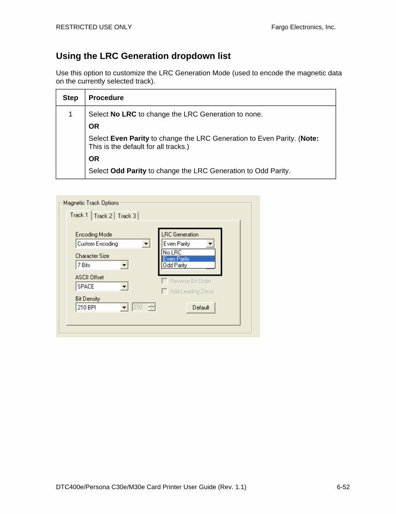
RESTRICTED USE ONLY Fargo Electronics, Inc.
DTC400e/Persona C30e/M30e Card Printer User Guide (Rev. 1.1) 6-52
Using the LRC Generation dropdown list
Use this option to customize the LRC Generation Mode (used to encode the magnetic data on the currently selected track).
Step Procedure
1 Select No LRC to change the LRC Generation to none.
OR
Select Even Parity to change the LRC Generation to Even Parity. (Note: This is the default for all tracks.)
OR
Select Odd Parity to change the LRC Generation to Odd Parity.

RESTRICTED USE ONLY Fargo Electronics, Inc.
DTC400e/Persona C30e/M30e Card Printer User Guide (Rev. 1.1) 6-53
Using the Character Parity dropdown list
Use this option to customize the Character Parity (used to encode the magnetic data on the currently selected track).
Step Procedure
1 Select No Parity to change the Character Parity to none.
OR
Select Even Parity to change the Character Parity to Even Parity.
OR
Select Odd Parity to change the Character Parity to Odd Parity. (Note: This is the default for all tracks.)

RESTRICTED USE ONLY Fargo Electronics, Inc.
DTC400e/Persona C30e/M30e Card Printer User Guide (Rev. 1.1) 6-54
Reviewing the ISO Track Locations
The magnetic Encoding Module encodes onto tracks in accordance with an ISO 7811-2 Magnetic Stripe. For track locations, review the display below.
TRACK1 0.110"
TRACK2 0.110"
TRACK3 0.110"
0.130"
0.140"
0.223" 0.353" 0.493"

RESTRICTED USE ONLY Fargo Electronics, Inc.
DTC400e/Persona C30e/M30e Card Printer User Guide (Rev. 1.1) 6-55
Sending the Track Information
Magnetic track data is sent in the form of text strings from the application software to the Printer Driver.
• In order for the Printer Driver to differentiate between Magnetic Track data and the rest of the printable objects, specific characters must be added to the magnetic data to be encoded.
• These specify the data that is to be encoded, the tracks to encode and mark the start and stop of the data string.
• In some cases, these specific characters are automatically added to the string of track data by ID software applications.
• In most cases, the user must carefully add these characters to the string of Magnetic Track data. If these characters are not added to the track data, the text intended for the Magnetic Track will appear as printed text on the card.
• To avoid this, track information must be entered as described below.
Step Procedure
1 When entering track data, the ~ (tilde) character is entered first, followed by the track number (1, 2 or 3) on which the data should encode. This is followed by the data to be encoded.
• The first character of this data string must be the track's specific Start Sentinel (SS) and the last character must be the specific End Sentinel (ES).
• The characters or data in between the SS and ES can include all of the valid characters specific to each track.
• The number of these characters, however, is limited by each track's maximum character capacity.
• When segmenting track data, the appropriate Field Separator (FS) must be used. The table below shows the SS, ES, FS and the valid characters defined for each track.
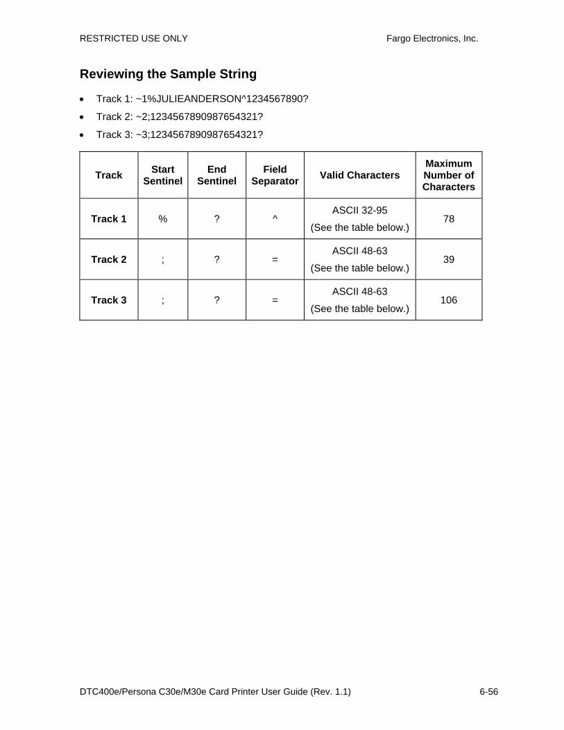
RESTRICTED USE ONLY Fargo Electronics, Inc.
DTC400e/Persona C30e/M30e Card Printer User Guide (Rev. 1.1) 6-56
Reviewing the Sample String
• Track 1: ~1%JULIEANDERSON^1234567890?
• Track 2: ~2;1234567890987654321?
• Track 3: ~3;1234567890987654321?
Track Start Sentinel
End Sentinel
Field Separator Valid Characters
Maximum Number of Characters
Track 1 % ? ^ ASCII 32-95
(See the table below.) 78
Track 2 ; ? = ASCII 48-63
(See the table below.) 39
Track 3 ; ? = ASCII 48-63
(See the table below.) 106

RESTRICTED USE ONLY Fargo Electronics, Inc.
DTC400e/Persona C30e/M30e Card Printer User Guide (Rev. 1.1) 6-57
Reviewing the ASCII Code and Character Table
ASCII Code Character ASCII Code Character ASCII Code Character
32 space 56 8 80 P
33 ! 57 9 81 Q
34 58 : 82 R
35 # 59 ; 83 S
36 $ 60 < 84 T
37 % 61 = 85 U
38 and 62 > 86 V
39 ' 63 ? 87 W
40 ( 64 @ 88 X
41 ) 65 A 89 Y
42 * 66 B 90 Z
43 + 67 C 91 [
44 ' 68 D 92 \
45 - 69 E 93 ]
46 . 70 F 94 ^
47 / 71 G 95 _
48 0 72 H
49 1 73 I
50 2 74 J
51 3 75 K
52 4 76 L
53 5 77 M
54 6 78 N
55 7 79 O

RESTRICTED USE ONLY Fargo Electronics, Inc.
DTC400e/Persona C30e/M30e Card Printer User Guide (Rev. 1.1) 6-58
Using the Overlay / Print Area tab (DTC400e/C30e/M30e) Use this option to control where the Overlay (O) Panel and/or the print area appear on a card. (Note: This option is helpful if, for example, you would like to omit or block out the overlay or printing around a card's smart chip or Magnetic Stripe.)
By default, this option is set to print and overlay the entire card. To customize the overlay and/or print area, select one of the options listed under "Overlay / Print Area."

RESTRICTED USE ONLY Fargo Electronics, Inc.
DTC400e/Persona C30e/M30e Card Printer User Guide (Rev. 1.1) 6-59
Enabling the Back options
Step Procedure
1 Select Print Both Sides under the Device Options tab to enable the Back option under the Overlay / Print Area. (Note: This same selection applies to the K Panel Resin back option.)

RESTRICTED USE ONLY Fargo Electronics, Inc.
DTC400e/Persona C30e/M30e Card Printer User Guide (Rev. 1.1) 6-60
Using the Front option (Overlay / Print Area)
Step Procedure
1 Select Front to view the Overlay/Print Area options for the front of the card.

RESTRICTED USE ONLY Fargo Electronics, Inc.
DTC400e/Persona C30e/M30e Card Printer User Guide (Rev. 1.1) 6-61
Using the Back option (Overlay / Print Area)
Step Procedure
1 Select Back to view the Overlay/Print area options for the back of the card.
(Note: The Back option is only available if Print Both Sides is selected.)
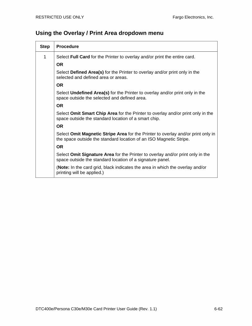
RESTRICTED USE ONLY Fargo Electronics, Inc.
DTC400e/Persona C30e/M30e Card Printer User Guide (Rev. 1.1) 6-62
Using the Overlay / Print Area dropdown menu
Step Procedure
1 Select Full Card for the Printer to overlay and/or print the entire card.
OR Select Defined Area(s) for the Printer to overlay and/or print only in the selected and defined area or areas.
OR Select Undefined Area(s) for the Printer to overlay and/or print only in the space outside the selected and defined area.
OR Select Omit Smart Chip Area for the Printer to overlay and/or print only in the space outside the standard location of a smart chip.
OR Select Omit Magnetic Stripe Area for the Printer to overlay and/or print only in the space outside the standard location of an ISO Magnetic Stripe.
OR Select Omit Signature Area for the Printer to overlay and/or print only in the space outside the standard location of a signature panel.
(Note: In the card grid, black indicates the area in which the overlay and/or printing will be applied.)

RESTRICTED USE ONLY Fargo Electronics, Inc.
DTC400e/Persona C30e/M30e Card Printer User Guide (Rev. 1.1) 6-63
See the previous page for the related procedure.

RESTRICTED USE ONLY Fargo Electronics, Inc.
DTC400e/Persona C30e/M30e Card Printer User Guide (Rev. 1.1) 6-64
Using the Overlay / Print Area
Use these Overlay / Print Area options to control both the print and overlay together or control each individually. (Note: Determine whether to use the Frontside option (via the Front radio button) or the Backside option (via the Back radio button).)
Step Procedure
1 Select For Print and Overlay for the defined area to apply to both the printing and overlay process.
OR Select For Overlay Only for the defined area to apply only to the overlay process. (Note: In this mode, printing will still be allowed over the entire card and only the overlay will be affected.)
OR Select For Print Only (No Overlay) for the defined area to apply only to the print process. (Important: In this mode, the overlay is completely disabled so it will not be applied.)
Caution: An overlay or an overlaminate must protect dye-sublimation printing or it will quickly begin to wear or fade.
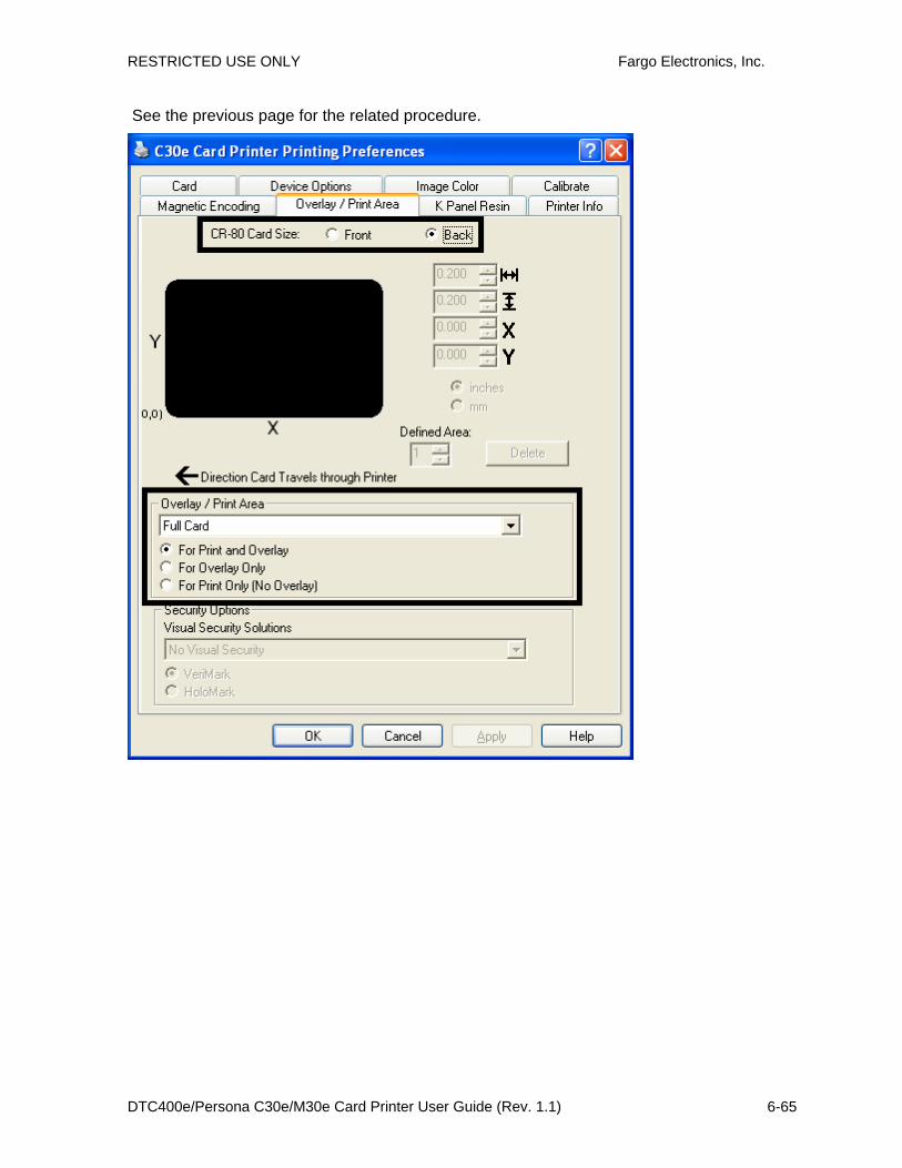
RESTRICTED USE ONLY Fargo Electronics, Inc.
DTC400e/Persona C30e/M30e Card Printer User Guide (Rev. 1.1) 6-65
See the previous page for the related procedure.

RESTRICTED USE ONLY Fargo Electronics, Inc.
DTC400e/Persona C30e/M30e Card Printer User Guide (Rev. 1.1) 6-66
Using the Defined Area Option
Step Procedure
1 a. Determine whether to use the Front option (via the Front radio button) or the Back option (via the Back radio button).
b. Select the Defined Area(s) option to activate the card grid in the upper half of the window. It is through this card grid that up to five (5) Defined Areas can be assigned.
2 When the card grid is first activated, a small black square will appear at its default size of .2" x .2" / 5mm x 5mm and at its default location in the lower left-hand corner (0, 0). This square represents the first defined area.
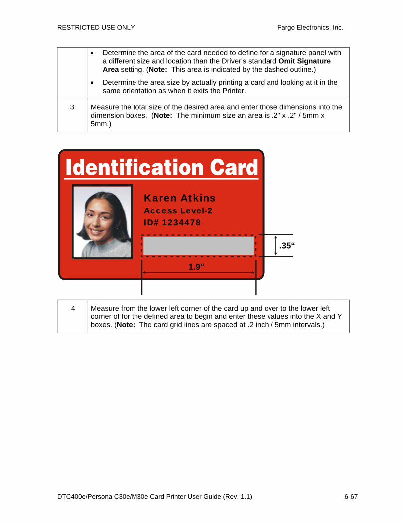
RESTRICTED USE ONLY Fargo Electronics, Inc.
DTC400e/Persona C30e/M30e Card Printer User Guide (Rev. 1.1) 6-67
• Determine the area of the card needed to define for a signature panel with a different size and location than the Driver's standard Omit Signature Area setting. (Note: This area is indicated by the dashed outline.)
• Determine the area size by actually printing a card and looking at it in the same orientation as when it exits the Printer.
3 Measure the total size of the desired area and enter those dimensions into the dimension boxes. (Note: The minimum size an area is .2" x .2" / 5mm x 5mm.)
.35“
1.9“
Karen AtkinsAccess Level-2ID# 1234478
4 Measure from the lower left corner of the card up and over to the lower left corner of for the defined area to begin and enter these values into the X and Y boxes. (Note: The card grid lines are spaced at .2 inch / 5mm intervals.)
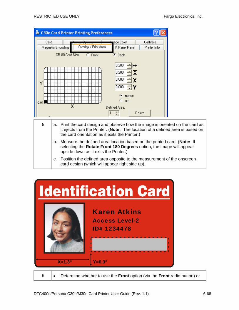
RESTRICTED USE ONLY Fargo Electronics, Inc.
DTC400e/Persona C30e/M30e Card Printer User Guide (Rev. 1.1) 6-68
5 a. Print the card design and observe how the image is oriented on the card as it ejects from the Printer. (Note: The location of a defined area is based on the card orientation as it exits the Printer.)
b. Measure the defined area location based on the printed card. (Note: If selecting the Rotate Front 180 Degrees option, the image will appear upside down as it exits the Printer.)
c. Position the defined area opposite to the measurement of the onscreen card design (which will appear right side up).
Y=0.3“X=1.3“
Karen AtkinsAccess Level-2ID# 1234478
6 • Determine whether to use the Front option (via the Front radio button) or

RESTRICTED USE ONLY Fargo Electronics, Inc.
DTC400e/Persona C30e/M30e Card Printer User Guide (Rev. 1.1) 6-69
the Back option (via the Back radio button).
• Use the Defined Area arrows to navigate back and forth from area to area in the Front or Backside area. (Note: The active area will always be highlighted with a dotted outline.)
• Define another area by clicking on the Defined Area UP arrow.
• Another .2" x .2" / 5mm x 5mm area will appear in the lower left-hand corner. (Note: This is the location in which all newly defined areas will first appear.)
• New areas are always created in the same position with the same size so it is recommended to move or resize them as they are created.
• All five defined or undefined areas can be added without moving the previous one to another location. The up arrow on the Defined Area control can be activated five times in a row and there are five areas added. After five areas are added there appears to be only one until you move each one to a different location.
• Delete an area by using the Defined Area arrows to select the area and click Delete. (Note: If all areas are deleted, the K Panel Resin options will automatically be deselected.)

RESTRICTED USE ONLY Fargo Electronics, Inc.
DTC400e/Persona C30e/M30e Card Printer User Guide (Rev. 1.1) 6-70
Using Security Options (Visual Security Solutions) (Front option only)
The Visual Security Solutions dropdown menu list will be used to enable and select which type of visual security will be used. The Visual Security dropdown list will be selectable only on the Front side (see below). Visual Security is not an option for the back side.
The following actions will occur when one of the Visual Security locations is selected.
• The Overlay / Print Area will be disabled.
• The Security Options become selectable.

RESTRICTED USE ONLY Fargo Electronics, Inc.
DTC400e/Persona C30e/M30e Card Printer User Guide (Rev. 1.1) 6-71
Selecting Orientation - Landscape under Card tab
Step Procedure
1 Select Landscape (below) under Orientation under the Card Size tab to use the Visual Security Solutions (A to D), as shown in this window.

RESTRICTED USE ONLY Fargo Electronics, Inc.
DTC400e/Persona C30e/M30e Card Printer User Guide (Rev. 1.1) 6-72
Selecting the Visual Security Solutions dropdown menu (A to D)
Step Procedure
1 Click the Visual Security Solutions dropdown menu (below) under the Landscape - Orientation (see above) to use the options shown in this display.
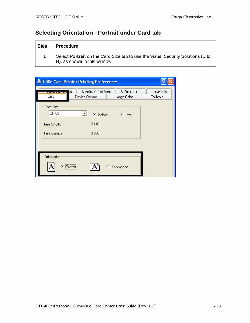
RESTRICTED USE ONLY Fargo Electronics, Inc.
DTC400e/Persona C30e/M30e Card Printer User Guide (Rev. 1.1) 6-73
Selecting Orientation - Portrait under Card tab
Step Procedure
1 Select Portrait on the Card Size tab to use the Visual Security Solutions (E to H), as shown in this window.

RESTRICTED USE ONLY Fargo Electronics, Inc.
DTC400e/Persona C30e/M30e Card Printer User Guide (Rev. 1.1) 6-74
Selecting the Visual Security Solutions dropdown menu (E to H)
Step Procedure
1 Click the Visual Security Solutions dropdown menu under the Portrait - Orientation (see above) to use the options shown below.

RESTRICTED USE ONLY Fargo Electronics, Inc.
DTC400e/Persona C30e/M30e Card Printer User Guide (Rev. 1.1) 6-75
Selecting the VeriMark radio button (Frontside option only)
Step Procedure
1 Click either VeriMark or HoloMark as shown below. The foil options are used to control the size of the exclusion area. (Note: When VeriMark is selected a rectangle-sized area is excluded, HoloMark uses a square sized area.)
2 Click VeriMark (below) for the rectangle-sized area.
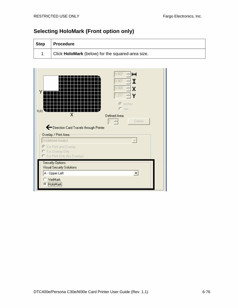
RESTRICTED USE ONLY Fargo Electronics, Inc.
DTC400e/Persona C30e/M30e Card Printer User Guide (Rev. 1.1) 6-76
Selecting HoloMark (Front option only)
Step Procedure
1 Click HoloMark (below) for the squared-area size.

RESTRICTED USE ONLY Fargo Electronics, Inc.
DTC400e/Persona C30e/M30e Card Printer User Guide (Rev. 1.1) 6-77
Reviewing the Custom VeriMark Card (Custom Graphic in a 2D foil)
The custom VeriMark image is stamped on blank, standard-sized cards. You can select one of eight positions (A to H), as shown in the Portrait and Landscape samples below.
Sample 1: VeriMark Card (Landscape - Orientation) - 4 positions (below)
A
D
B
C
Sample 2: VeriMark Card (Portrait - Orientation) - 4 positions (below)
FE
G H

RESTRICTED USE ONLY Fargo Electronics, Inc.
DTC400e/Persona C30e/M30e Card Printer User Guide (Rev. 1.1) 6-78
Reviewing the Custom HoloMark Card (Custom Graphic in a 2D foil)
The custom HoloMark image is stamped on blank, standard-sized cards. You can select one of eight positions (A to H), as shown in the Portrait and Landscape samples below.
Sample 1: HoloMark Card (Landscape - Orientation) - 4 positions (below)
DC
BA
Sample 2: HoloMark Card (Portrait - Orientation) - 4 positions (below)
FE
G H

RESTRICTED USE ONLY Fargo Electronics, Inc.
DTC400e/Persona C30e/M30e Card Printer User Guide (Rev. 1.1) 6-79
Using the K Panel Resin tab (DTC400e/C30e/M30e) Select the K Panel Resin option to control where the resin black (K) panel of a full-color Ribbon is printed.
• If printing with a resin-only Ribbon type all K Panel Resin options will be grayed out.
• Resin black text is desirable due to its sharp, saturated black coloring and resin black bar codes are often required by Ultra Violet barcode readers to ensure readability when scanned.)

RESTRICTED USE ONLY Fargo Electronics, Inc.
DTC400e/Persona C30e/M30e Card Printer User Guide (Rev. 1.1) 6-80
Enabling the Frontside and Backside options
Step Procedure
1 Select Print Both Sides under the Device Options tab to enable the Backside option under the K Panel Resin tab. (Note: This same selection applies to the K Panel Resin backside option.)
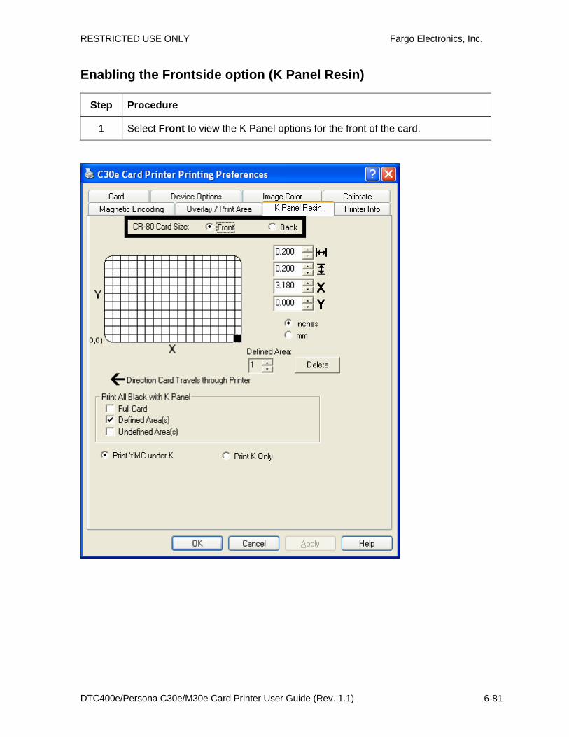
RESTRICTED USE ONLY Fargo Electronics, Inc.
DTC400e/Persona C30e/M30e Card Printer User Guide (Rev. 1.1) 6-81
Enabling the Frontside option (K Panel Resin)
Step Procedure
1 Select Front to view the K Panel options for the front of the card.

RESTRICTED USE ONLY Fargo Electronics, Inc.
DTC400e/Persona C30e/M30e Card Printer User Guide (Rev. 1.1) 6-82
Enabling the Backside option (K Panel Resin)
Step Procedure
1 Select Back to view the K Panel Resin options for the back of the card.
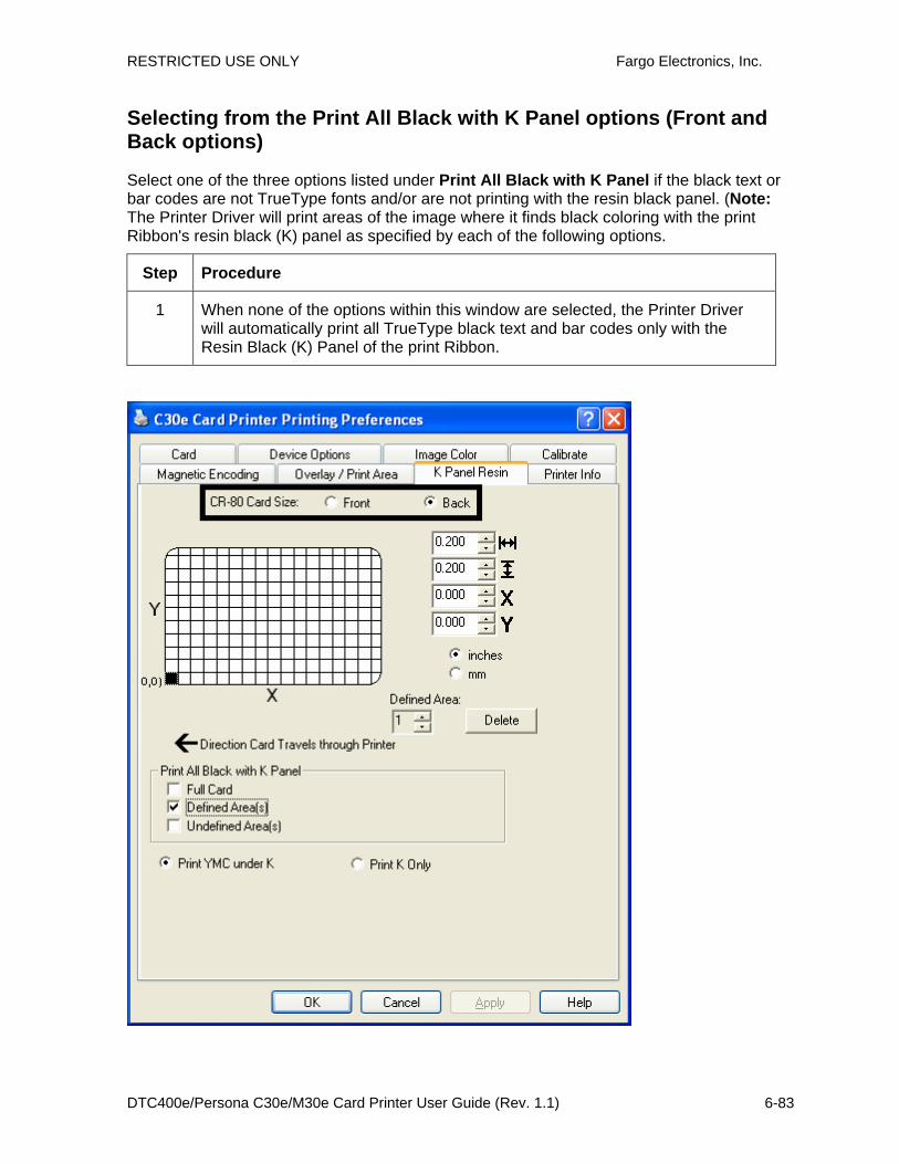
RESTRICTED USE ONLY Fargo Electronics, Inc.
DTC400e/Persona C30e/M30e Card Printer User Guide (Rev. 1.1) 6-83
Selecting from the Print All Black with K Panel options (Front and Back options)
Select one of the three options listed under Print All Black with K Panel if the black text or bar codes are not TrueType fonts and/or are not printing with the resin black panel. (Note: The Printer Driver will print areas of the image where it finds black coloring with the print Ribbon's resin black (K) panel as specified by each of the following options.
Step Procedure
1 When none of the options within this window are selected, the Printer Driver will automatically print all TrueType black text and bar codes only with the Resin Black (K) Panel of the print Ribbon.

RESTRICTED USE ONLY Fargo Electronics, Inc.
DTC400e/Persona C30e/M30e Card Printer User Guide (Rev. 1.1) 6-84
Selecting the Full Card option (Front and Back options)
Step Procedure
1 Select Full Card for the Printer Driver to print the resin black (K) panel for all black found within all areas of the image.

RESTRICTED USE ONLY Fargo Electronics, Inc.
DTC400e/Persona C30e/M30e Card Printer User Guide (Rev. 1.1) 6-85
Selecting the Defined Area(s) option (Front and Back options)
Step Procedure
1 Select Defined Area(s) for the Printer Driver to print the resin black (K) panel for all black found only in a desired and defined area or areas.
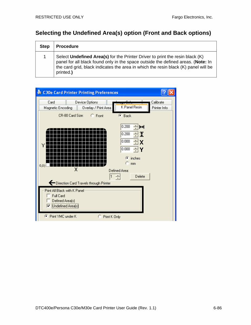
RESTRICTED USE ONLY Fargo Electronics, Inc.
DTC400e/Persona C30e/M30e Card Printer User Guide (Rev. 1.1) 6-86
Selecting the Undefined Area(s) option (Front and Back options)
Step Procedure
1 Select Undefined Area(s) for the Printer Driver to print the resin black (K) panel for all black found only in the space outside the defined areas. (Note: In the card grid, black indicates the area in which the resin black (K) panel will be printed.)

RESTRICTED USE ONLY Fargo Electronics, Inc.
DTC400e/Persona C30e/M30e Card Printer User Guide (Rev. 1.1) 6-87
Selecting the Defined Area(s) function (Front and Back options)
To define an area, refer to the following steps:
Step Procedure
1 Click Defined Area(s). (Note: This will activate the card grid in the upper half of the window. It is through this card grid that up to five areas can be defined.)
When the card grid is first activated, a small square will appear at its default size of .2" x .2" / 5mm x 5mm and at its default location in the lower left-hand corner (0, 0). This square represents the first defined area.
(Note: Changing the orientation of the card in the Card Tab will change the appearance of this Tab.)
2 a. Determine the area of the card necessary to define. In the sample (below), this area is indicated by the dashed outline.
b. Determine the size of this area by actually printing a card and looking at it in the same orientation as when it exits the Printer.

RESTRICTED USE ONLY Fargo Electronics, Inc.
DTC400e/Persona C30e/M30e Card Printer User Guide (Rev. 1.1) 6-88
3 Measure the total size for the area and enter those dimensions into the dimension boxes. (Note: The minimum size an area can be is .2" x .2" / 5mm x 5mm.)
* 172355*
Karen AtkinsAccess Level-2ID# 1234478 1.2“
1.8“
4 a. Once the area is sized properly measure from the lower left corner of the card up and over to the lower left corner for the defined area to begin.
b. Enter these values into the X and Y boxes.
(Note: The card grid lines are spaced at .2 inch / 5mm intervals.)
5 a. Print the card design and note how the image is oriented on the card as it ejects from the Printer. (Note: The location of a defined area is based on the card orientation as it exits the Printer.)
b. Measure the defined area location based on the printed card. (Note: If selecting Rotate Front 180 Degrees, the image will appear upside-down as it exits the Printer. In this case, position the defined area opposite to the measurement from the onscreen card design, which will appear right side up.)
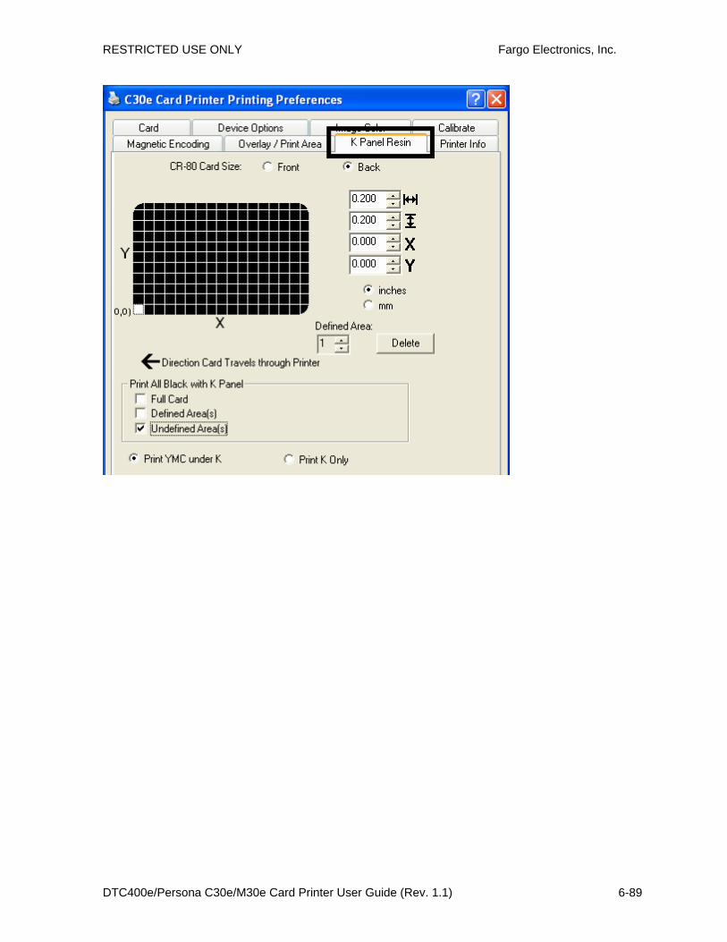
RESTRICTED USE ONLY Fargo Electronics, Inc.
DTC400e/Persona C30e/M30e Card Printer User Guide (Rev. 1.1) 6-89
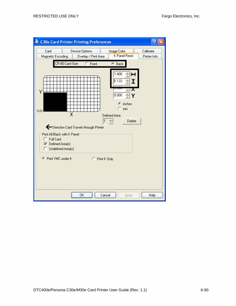
RESTRICTED USE ONLY Fargo Electronics, Inc.
DTC400e/Persona C30e/M30e Card Printer User Guide (Rev. 1.1) 6-90

RESTRICTED USE ONLY Fargo Electronics, Inc.
DTC400e/Persona C30e/M30e Card Printer User Guide (Rev. 1.1) 6-91
* 172355*
Karen AtkinsAccess Level-2ID# 1234478
Y=0.2“X=1.4“

RESTRICTED USE ONLY Fargo Electronics, Inc.
DTC400e/Persona C30e/M30e Card Printer User Guide (Rev. 1.1) 6-92
Refer to the previous procedure.
6 Define another area by clicking the Defined Area up arrow. (Note: Another .2" x .2" / 5mm x 5mm area will appear in the lower left-hand corner. This is the location in which all newly defined areas will first appear.)
7 • Use the Defined Area arrows to navigate back and forth from area to area. (Note: The active area will always be highlighted with a dotted outline. Up to 5 areas can be defined.)
• New areas are always created in the same position with the same size so it is recommended to move or resize them as they are created.
• All five defined or undefined areas can be added without moving the previous one to another location. The up arrow on the Defined Area control can be activated five times in a row and there are five areas added. After five areas are added there appears to be only one until you move each one to a different location.
8 Delete an area by using the Defined Area arrows to select the area and clicking Delete. (Note: If all areas are deleted, the K Panel Resin options will automatically be deselected.)

RESTRICTED USE ONLY Fargo Electronics, Inc.
DTC400e/Persona C30e/M30e Card Printer User Guide (Rev. 1.1) 6-93
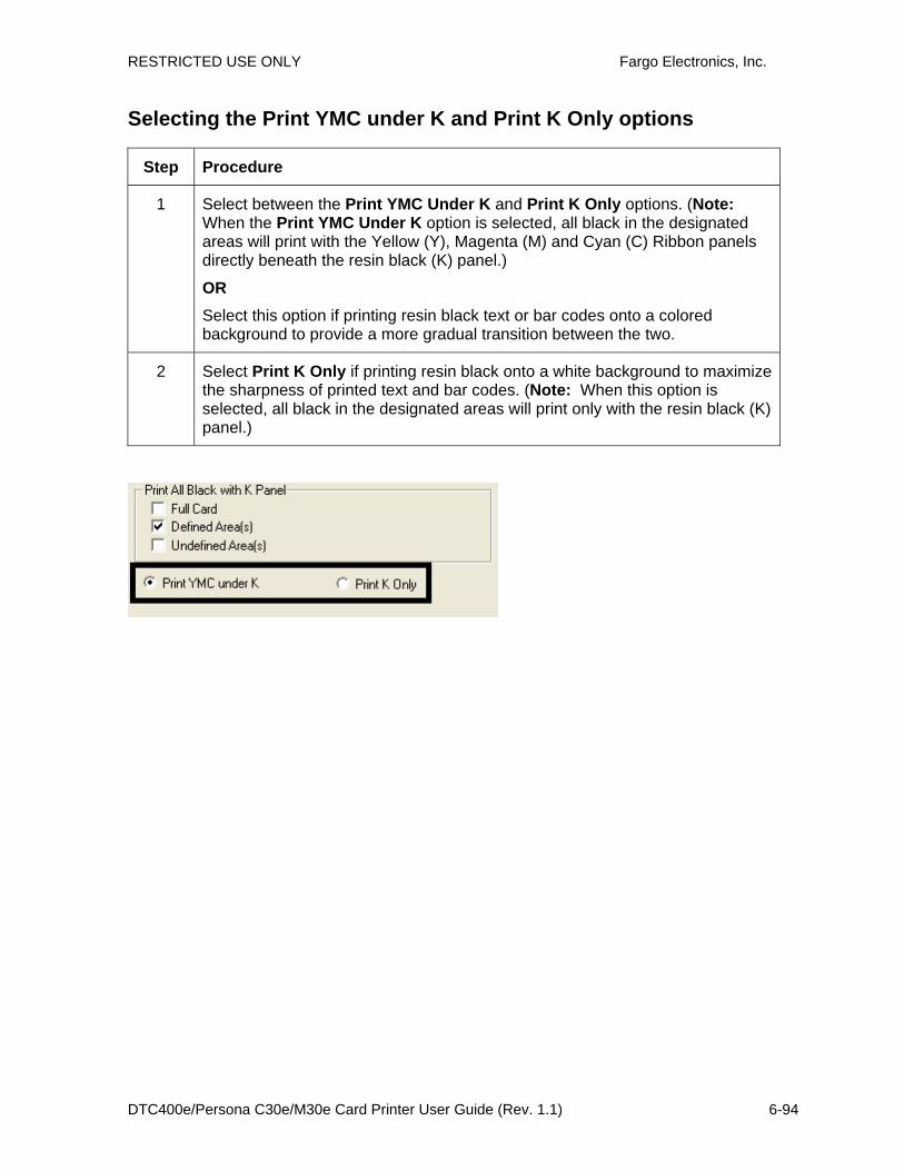
RESTRICTED USE ONLY Fargo Electronics, Inc.
DTC400e/Persona C30e/M30e Card Printer User Guide (Rev. 1.1) 6-94
Selecting the Print YMC under K and Print K Only options
Step Procedure
1 Select between the Print YMC Under K and Print K Only options. (Note: When the Print YMC Under K option is selected, all black in the designated areas will print with the Yellow (Y), Magenta (M) and Cyan (C) Ribbon panels directly beneath the resin black (K) panel.)
OR
Select this option if printing resin black text or bar codes onto a colored background to provide a more gradual transition between the two.
2 Select Print K Only if printing resin black onto a white background to maximize the sharpness of printed text and bar codes. (Note: When this option is selected, all black in the designated areas will print only with the resin black (K) panel.)

RESTRICTED USE ONLY Fargo Electronics, Inc.
DTC400e/Persona C30e/M30e Card Printer User Guide (Rev. 1.1) 6-95
Using the Printer Info tab (DTC400e/C30e/M30e) Use the options on this tab to view information about the Ribbon installed in the Printer.
C30e
M30e
RESTRICTED USE ONLY Fargo Electronics, Inc.
DTC400e/Persona C30e/M30e Card Printer User Guide (Rev. 1.1) 6-96
Reviewing the Ribbon Information
Step Procedure
1 Use the Ribbon information to determine which Ribbon is being used to print with and its part number.
Reviewing the Ribbon Level Indicator
Step Procedure
1 Use the Ribbon Level indicator to view approximately how much Ribbon is left.

RESTRICTED USE ONLY Fargo Electronics, Inc.
DTC400e/Persona C30e/M30e Card Printer User Guide (Rev. 1.1) 6-97
Using the Printer Calibration Utility (DTC400e/C30e/M30e) Access the Settings dialog box via the Settings button on the Calibrate tab. Use the adjustment mode to change the Printer's internal settings. (Note: The Card Printer is equipped with an internal adjustment mode programmable through the Settings dialog box. This dialog box is accessible only if the Printer is powered ON, it is in Ready Mode and it is properly connected to the PC.)
Caution! These settings are optimized at the factory. In most cases, these settings can be used without changing them.

RESTRICTED USE ONLY Fargo Electronics, Inc.
DTC400e/Persona C30e/M30e Card Printer User Guide (Rev. 1.1) 6-98
Using the Image Darkness Option
Use this option to set the overall darkness of the printed image by increasing or decreasing the amount of heat used by the Printhead when printing.
Step Procedure
1 Lighten the printed image by clicking the down arrow to enter a negative value and decrease the amount of Printhead heat.
OR Darken the image by clicking the up arrow to enter a positive value and increase the amount of Printhead heat.
Caution: If the value is set too high, the Ribbon may jam or even break.
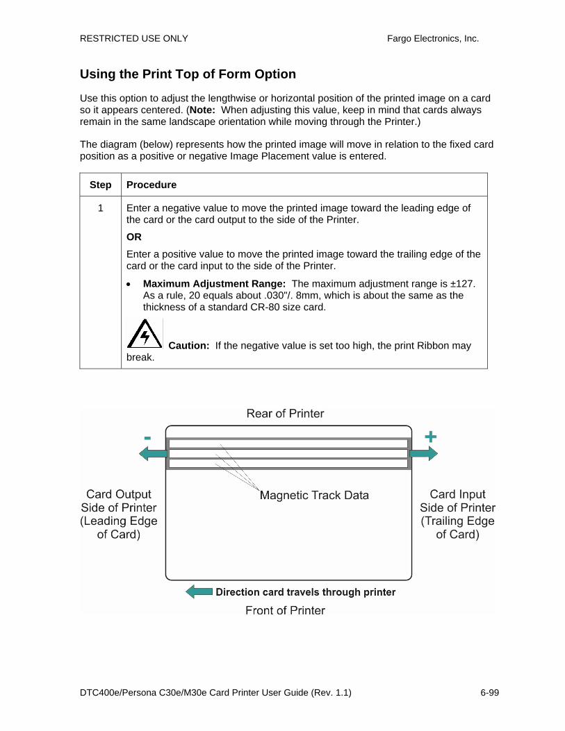
RESTRICTED USE ONLY Fargo Electronics, Inc.
DTC400e/Persona C30e/M30e Card Printer User Guide (Rev. 1.1) 6-99
Using the Print Top of Form Option
Use this option to adjust the lengthwise or horizontal position of the printed image on a card so it appears centered. (Note: When adjusting this value, keep in mind that cards always remain in the same landscape orientation while moving through the Printer.)
The diagram (below) represents how the printed image will move in relation to the fixed card position as a positive or negative Image Placement value is entered.
Step Procedure
1 Enter a negative value to move the printed image toward the leading edge of the card or the card output to the side of the Printer.
OR Enter a positive value to move the printed image toward the trailing edge of the card or the card input to the side of the Printer.
• Maximum Adjustment Range: The maximum adjustment range is ±127. As a rule, 20 equals about .030"/. 8mm, which is about the same as the thickness of a standard CR-80 size card.
Caution: If the negative value is set too high, the print Ribbon may break.

RESTRICTED USE ONLY Fargo Electronics, Inc.
DTC400e/Persona C30e/M30e Card Printer User Guide (Rev. 1.1) 6-100
Using the Print End of Form Option
Use this option to reduce or increase the overall printable area in order to optimize edge-to-edge printing toward the trailing edge of a card. (Note: When adjusting this value, keep in mind that cards always remains in the same position while moving through the Printer.)
The diagram (below) represents how the end of form will move in relation to the fixed card position as a positive or negative Print End of Form value is entered.
Step Procedure
1 Enter a negative value to reduce the Print End of Form and move the end of the printable area more toward the leading edge of the card.
OR Enter a positive value to increase the print length and move the end of the printable area more toward the trailing edge of the card.
a. Maximum Adjustment Range: The maximum adjustment range is ±127. As a rule, 20 equals about .030"/. 8mm, which is about the same as the thickness of a standard CR-80 size card.)

RESTRICTED USE ONLY Fargo Electronics, Inc.
DTC400e/Persona C30e/M30e Card Printer User Guide (Rev. 1.1) 6-101
Using the Print Left of Form Option
Use this option to adjust the vertical position of the printed image on a card so it appears centered. (Note: When adjusting this value, keep in mind that cards always remain in the same landscape orientation while moving through the Printer.)
Step Procedure
1 Enter a negative value to move the image towards the bottom edge of the card (See image below),
OR
Enter a positive value to move the image towards the back top edge of the card (see image below).
• Maximum Adjustment Range: The maximum adjustment range is -75 to +15. As a rule, 10 equals about .030"/. 8mm. This is about the same as the thickness of a standard CR-80 size card.

RESTRICTED USE ONLY Fargo Electronics, Inc.
DTC400e/Persona C30e/M30e Card Printer User Guide (Rev. 1.1) 6-102
Using the Magnetic Encoder Voltage Offset Option
Use this option to adjust the voltage of the Magnetic Encoder.
• Encoder voltage is set from the factory at a default of 7.24vdc for Hi-Co Magnetic cards and 2.54vdc for Lo-Co Magnetic cards.
• Depending on the cards that are being used, it may be necessary to adjust the Encoder voltage out of default.
See the next two procedures for instructions on adjusting the Magnetic Encoder Voltage. (Note: The required Encoder voltage for the cards will need to be known in order to properly set the Encoder Voltage Offset value. This information should be available through the card manufacturer or reseller.)

RESTRICTED USE ONLY Fargo Electronics, Inc.
DTC400e/Persona C30e/M30e Card Printer User Guide (Rev. 1.1) 6-103
Adjusting the Hi-Co Voltage Offset
Step Procedure
1 Identify the Magnetic Encoder voltage required by the cards. (Note: The required encoder voltage for the cards will need to be known in order to properly set the Encoder Voltage Offset value. This information should be available through the card manufacturer or reseller).
2 Use the following equation to identify the proper Mag Hi-Co Voltage Offset value
• ((((36500/(((<Desired Voltage>+4.6)/1.23)-1))-2670)/39.0625) – 40)X-1
For example: Required Encoder Voltage = 9vdc
• ((((36500/(((9+4.6)/1.23)-1))-2670)/39.0625) – 40)X-1 = 15
3 Change the Mag Hi-Co Voltage Offset value.
I.E 15
4 Use the Diagnostic Utility to run a Magnetic Self test and verify encoded quality.

RESTRICTED USE ONLY Fargo Electronics, Inc.
DTC400e/Persona C30e/M30e Card Printer User Guide (Rev. 1.1) 6-104
Adjusting the Lo-Co Voltage Offset
Step Procedure
1 Identify the Magnetic Encoder voltage required by the cards. (Note: The required encoder voltage for the cards will need to be known in order to properly set the Encoder Voltage Offset value. This information should be available through the card manufacturer or reseller).
2 Use the following equation to identify the proper Mag Lo-Co Voltage Offset value
• ((((36500/(((<Desired Voltage>+4.6)/1.23)-1))-2670)/39.0625) – 126)X-1
For example: Required Encoder Voltage = 1.5vdc
• ((((36500/(((1.5+4.6)/1.23)-1))-2670)/39.0625) – 126)X-1 = -42
3 Change the Mag Lo-Co Voltage Offset value.
I.E -42
4 Use the Diagnostic Utility to run a Magnetic Self test and verify encoded quality.

RESTRICTED USE ONLY Fargo Electronics, Inc.
DTC400e/Persona C30e/M30e Card Printer User Guide (Rev. 1.1) 6-105
Using the Mag Top of Form Option
Use this option only if the Printer has a built-in Magnetic Stripe encoder. (Note: If so, use this option to shift the starting point of where the Printer will begin encoding the magnetic track data on a card's Magnetic Stripe. When adjusting this value, keep in mind that a card and its Magnetic Stripe will always remain in the same relative position as the card travels through the Printer.)
The diagram (below) represents how the magnetic data will move in relation to the fixed position of a card's Magnetic Stripe as a positive or negative Magnetic Offset value is entered. (Note: For this diagram, imagine that the card is transparent and the card's Magnetic stripe can be seen through the top or front side of the card.)
Step Procedure
1 Enter a negative value to move the start of the magnetic data more toward the leading edge of the card or the card output to the side of the Printer.
OR Enter a positive value to move the start of the magnetic data toward the trailing edge of the card or the card input to the side of the Printer.
• Magnetic Data Direction: The arrows on these buttons indicate the direction the magnetic data will move on the card's Magnetic Stripe.
• Maximum Adjustment Range: The maximum adjustment range is ± 127. As a rule, 20 equals about .030"/. 8mm.) (Note: Keep this in mind when adjusting this option to avoid over-adjusting.)
Caution: If the negative value is set too high, the Printer may start encoding before the card's Magnetic Stripe reaches the encoding head.
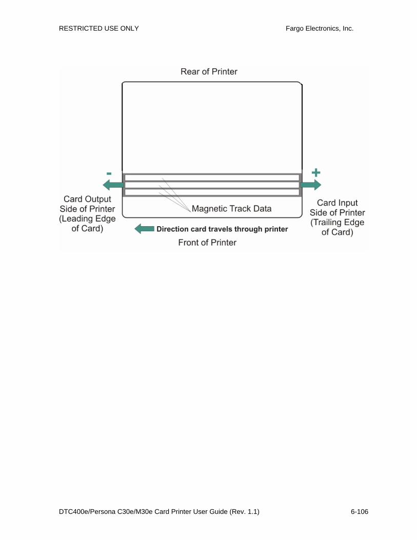
RESTRICTED USE ONLY Fargo Electronics, Inc.
DTC400e/Persona C30e/M30e Card Printer User Guide (Rev. 1.1) 6-106

RESTRICTED USE ONLY Fargo Electronics, Inc.
DTC400e/Persona C30e/M30e Card Printer User Guide (Rev. 1.1) 6-107
Using the Ribbon Tension Option
Step Procedure
1 Use the Ribbon Tension option to increase the amount of tension (drag) on the Ribbon during printing.
Enter a negative value to decrease the amount of tension that is placed on the Ribbon during printing
OR
Enter a positive value to increases the amount of tension that is placed on the Ribbon during printing.

RESTRICTED USE ONLY Fargo Electronics, Inc.
DTC400e/Persona C30e/M30e Card Printer User Guide (Rev. 1.1) 6-108
Using the Flipper Home Offset Option
Use this option to change the Flipper angle relative to home/horizontal position. This is done in order to adjust angle of travel to and from the Printer and Flipper Module.
Step Procedure
1 Enter a negative value to position a card to enter the Printer at an upward angle.
Or Enter a positive value to position a card to enter the Printer at a descending angle.
(Maximum Adjustment Range: The maximum adjustment range is ± 5. 1 is approximately 1 degree.)
Using the Flipper Center Offset Option
Use this option to change the card position on the Flipper Table, relative to the center, for flipping. (Note: This is important to maintain the proper clearance with surrounding objects when flipping a card.)
Step Procedure
1 Enter a negative value to position a card closer to the output of the Printer when the Flipper is in home/horizontal position.
Or Enter a positive value to position a card closer to the output of the Flipper Module when the Flipper is in home/horizontal position.
(Maximum Adjustment Range: The maximum adjustment range is ± 127. As a rule, 20 equals about .030”/.8 mm, which is about the same as the thickness of a standard CR-80 size card.)
Caution: If the offset is set too high or low, the card may jam in the Flipper Module when flipping.

RESTRICTED USE ONLY Fargo Electronics, Inc.
DTC400e/Persona C30e/M30e Card Printer User Guide (Rev. 1.1) 6-109
Using the Flipper Smart Angle Offset Option
Use this option to change the Flipper angle relative to the default smart card loading position. This is done in order to adjust travel to and from the Flipper and the Smart Card Docking Module.
Step Procedure
1 Enter a negative value to decrease the amount of Flipper angular movement from the home position to the smart card loading position.
Or Enter a positive value to increase the amount of Flipper angular movement from the home position to the smart card loading position.
(Maximum Adjustment Range: The maximum adjustment range is ± 5. 1 is approximately 1 degree.)
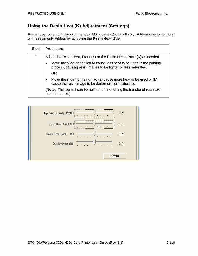
RESTRICTED USE ONLY Fargo Electronics, Inc.
DTC400e/Persona C30e/M30e Card Printer User Guide (Rev. 1.1) 6-110
Using the Resin Heat (K) Adjustment (Settings)
Printer uses when printing with the resin black panel(s) of a full-color Ribbon or when printing with a resin-only Ribbon by adjusting the Resin Heat slide.
Step Procedure
1 Adjust the Resin Heat, Front (K) or the Resin Head, Back (K) as needed.
• Move the slider to the left to cause less heat to be used in the printing process, causing resin images to be lighter or less saturated.
OR
• Move the slider to the right to (a) cause more heat to be used or (b) cause the resin image to be darker or more saturated.
(Note: This control can be helpful for fine-tuning the transfer of resin text and bar codes.)

RESTRICTED USE ONLY Fargo Electronics, Inc.
DTC400e/Persona C30e/M30e Card Printer User Guide (Rev. 1.1) 6-111
Using the Print Temperature Offset
Step Procedure
1 Adjust the printing temperature for the rewriteable cards as needed.
• Increase the Current Setting to cause more heat to be used in the printing process.
OR
• Decrease the Current Setting to cause less heat to be used in the printing process.
(Note: Print Temp Offset provides user ability to control Printhead heat level when the Print (Write) Operation is performed on rewriteable cards. Higher heat level needs to be applied for darker printing on rewriteable cards. A lower setting will produce a lighter image on rewriteable cards accordingly)
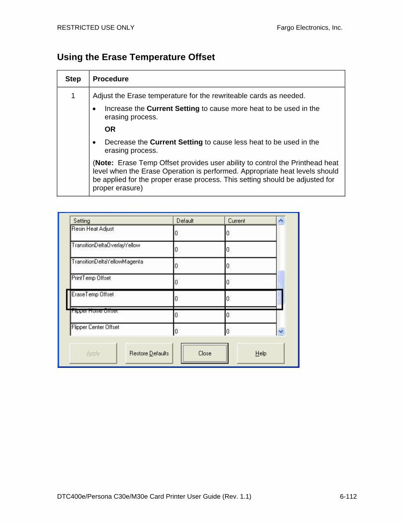
RESTRICTED USE ONLY Fargo Electronics, Inc.
DTC400e/Persona C30e/M30e Card Printer User Guide (Rev. 1.1) 6-112
Using the Erase Temperature Offset
Step Procedure
1 Adjust the Erase temperature for the rewriteable cards as needed.
• Increase the Current Setting to cause more heat to be used in the erasing process.
OR
• Decrease the Current Setting to cause less heat to be used in the erasing process.
(Note: Erase Temp Offset provides user ability to control the Printhead heat level when the Erase Operation is performed. Appropriate heat levels should be applied for the proper erase process. This setting should be adjusted for proper erasure)

RESTRICTED USE ONLY Fargo Electronics, Inc.
DTC400e/Persona C30e/M30e Card Printer User Guide (Rev. 1.1) 6-113
Using the Flipper Prox Offset Option
Step Procedure
1 Normally the Prox encoder is installed into Bay1 and no adjustment is necessary.
• This setting is factory set at 0.
• This setting option relates to the Prox encoder installed into Bay 2.
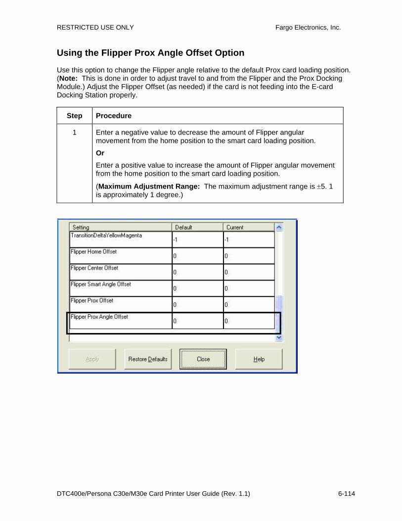
RESTRICTED USE ONLY Fargo Electronics, Inc.
DTC400e/Persona C30e/M30e Card Printer User Guide (Rev. 1.1) 6-114
Using the Flipper Prox Angle Offset Option
Use this option to change the Flipper angle relative to the default Prox card loading position. (Note: This is done in order to adjust travel to and from the Flipper and the Prox Docking Module.) Adjust the Flipper Offset (as needed) if the card is not feeding into the E-card Docking Station properly.
Step Procedure
1 Enter a negative value to decrease the amount of Flipper angular movement from the home position to the smart card loading position.
Or Enter a positive value to increase the amount of Flipper angular movement from the home position to the smart card loading position.
(Maximum Adjustment Range: The maximum adjustment range is ±5. 1 is approximately 1 degree.)

RESTRICTED USE ONLY Fargo Electronics, Inc.
DTC400e/Persona C30e/M30e Card Printer User Guide (Rev. 1.1) 7-1
Section 7: Using the YMCFKO Ribbon in the Workbench
This process allows the user to configure the data that is printed with the fluorescent panel of an YMCFKO or YMCFKOK Ribbon. Any software program may be used to print the special fluorescent panel of the ribbon to a card once the driver and Workbench are set up correctly.
Step Procedure
1 From the Driver Printing Preferences click on Diagnostics to bring up the Fargo Workbench Printer Utility.

RESTRICTED USE ONLY Fargo Electronics, Inc.
DTC400e/Persona C30e/M30e Card Printer User Guide (Rev. 1.1) 7-2
2 Set the ribbon for YMCFKO or YMCFKOK in the Printing Preferences.
The Auto Detect button may also be used. The F panel ribbon must be installed for this process to work.
3 Once the driver is set for YMCFKO ribbon and Workbench parameters are set up correctly, the image printed from any software program will show the Florescent images as place on the template.
4 Click the Print Security applet group and select the Security Imaging applet.
Check the Enable Secure Imaging Checkbox.

RESTRICTED USE ONLY Fargo Electronics, Inc.
DTC400e/Persona C30e/M30e Card Printer User Guide (Rev. 1.1) 7-3

RESTRICTED USE ONLY Fargo Electronics, Inc.
DTC400e/Persona C30e/M30e Card Printer User Guide (Rev. 1.1) 7-4
Adding a Secure ID to the Card
Step Procedure
5 Click on the Secure ID box on the left. Click and drag a box onto the Template. Move and size as needed.

RESTRICTED USE ONLY Fargo Electronics, Inc.
DTC400e/Persona C30e/M30e Card Printer User Guide (Rev. 1.1) 7-5
Changing the Secure ID Properties
Step Procedure
6 On the Template right click on the Secure ID box for the options shown below.
Step 4. Right mouse click on the Secure ID box for these options:
1. Use the Font options. 2. Move to Fluorescing Panel. 3. Move to Resin Panel. 4. Rotate clockwise. 5. Rotate counter-clockwise. 6. Delete the Secure ID box.
Step 2. Click .Secure ID
Step 3. On the Template box, click and drag a box on the Security ID template.
Step 1. Check the checkbox.
Enable Secure Imaging
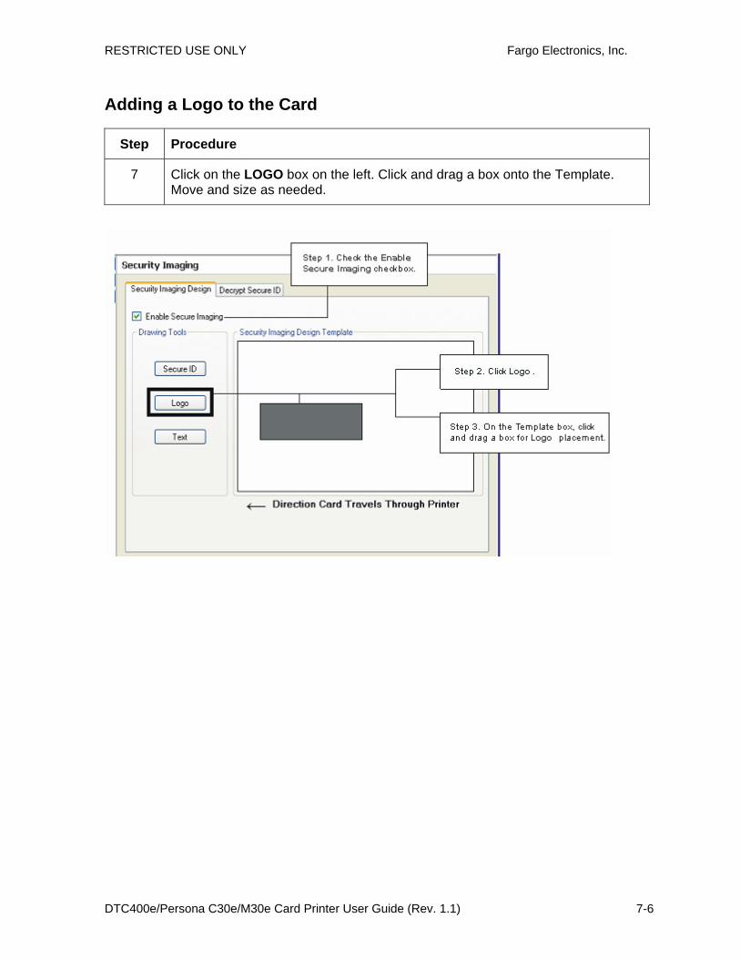
RESTRICTED USE ONLY Fargo Electronics, Inc.
DTC400e/Persona C30e/M30e Card Printer User Guide (Rev. 1.1) 7-6
Adding a Logo to the Card
Step Procedure
7 Click on the LOGO box on the left. Click and drag a box onto the Template. Move and size as needed.
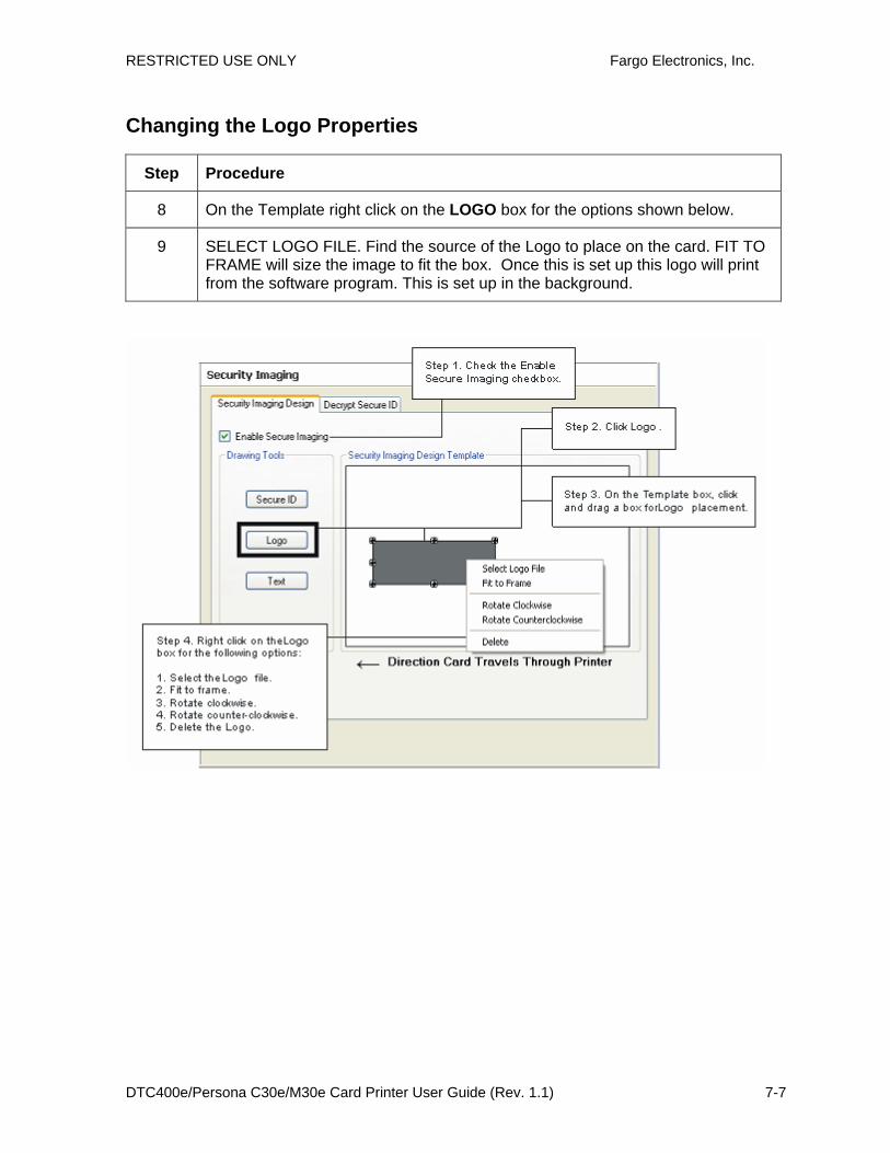
RESTRICTED USE ONLY Fargo Electronics, Inc.
DTC400e/Persona C30e/M30e Card Printer User Guide (Rev. 1.1) 7-7
Changing the Logo Properties
Step Procedure
8 On the Template right click on the LOGO box for the options shown below.
9 SELECT LOGO FILE. Find the source of the Logo to place on the card. FIT TO FRAME will size the image to fit the box. Once this is set up this logo will print from the software program. This is set up in the background.
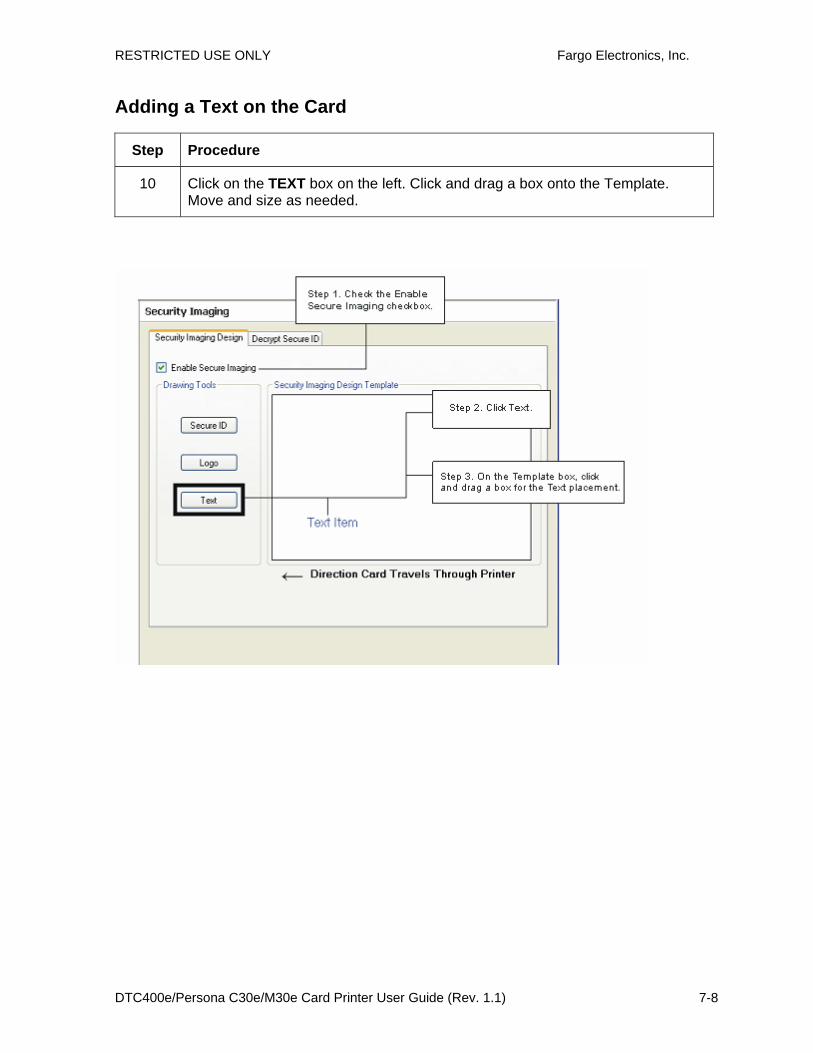
RESTRICTED USE ONLY Fargo Electronics, Inc.
DTC400e/Persona C30e/M30e Card Printer User Guide (Rev. 1.1) 7-8
Adding a Text on the Card
Step Procedure
10 Click on the TEXT box on the left. Click and drag a box onto the Template. Move and size as needed.
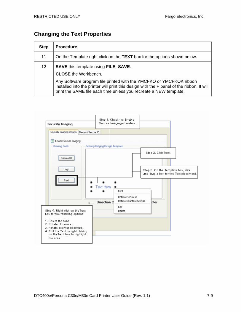
RESTRICTED USE ONLY Fargo Electronics, Inc.
DTC400e/Persona C30e/M30e Card Printer User Guide (Rev. 1.1) 7-9
Changing the Text Properties
Step Procedure
11 On the Template right click on the TEXT box for the options shown below.
12 SAVE this template using FILE- SAVE.
CLOSE the Workbench.
Any Software program file printed with the YMCFKO or YMCFKOK ribbon installed into the printer will print this design with the F panel of the ribbon. It will print the SAME file each time unless you recreate a NEW template.
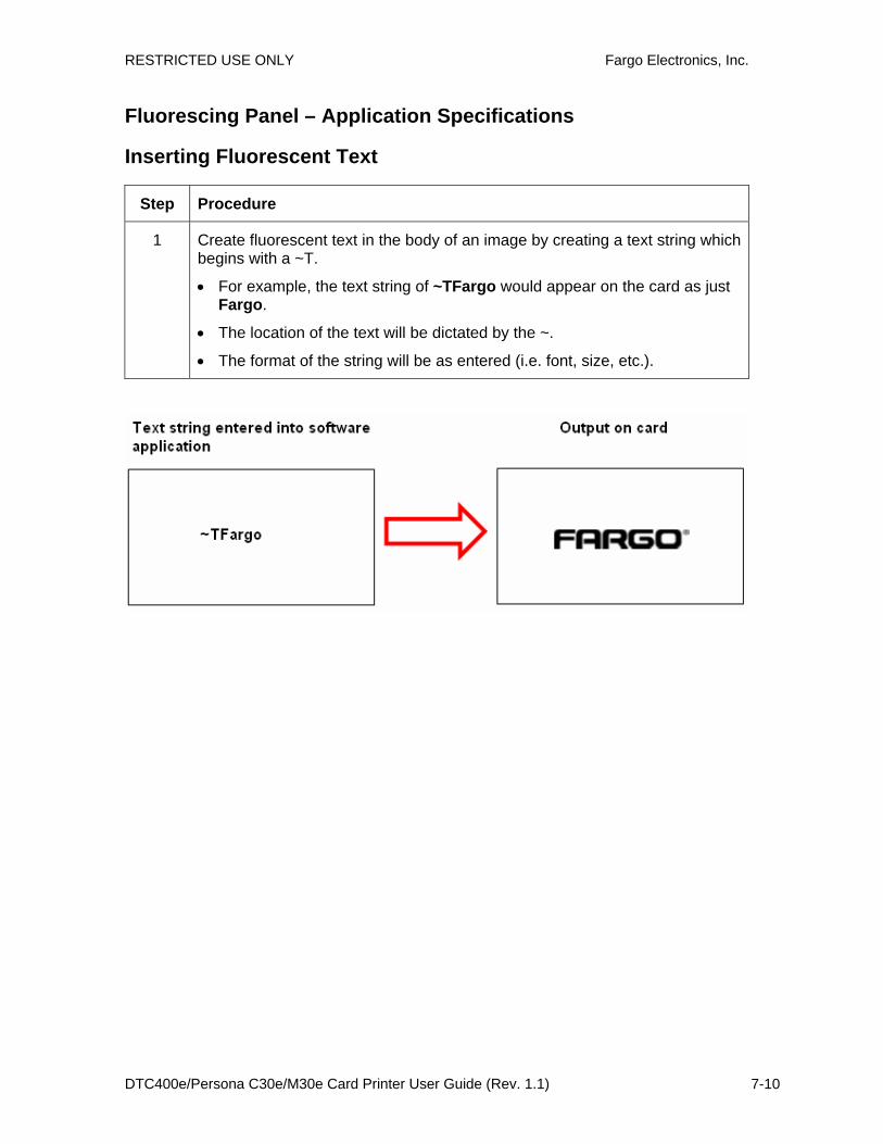
RESTRICTED USE ONLY Fargo Electronics, Inc.
DTC400e/Persona C30e/M30e Card Printer User Guide (Rev. 1.1) 7-10
Fluorescing Panel – Application Specifications
Inserting Fluorescent Text
Step Procedure
1 Create fluorescent text in the body of an image by creating a text string which begins with a ~T.
• For example, the text string of ~TFargo would appear on the card as just Fargo.
• The location of the text will be dictated by the ~.
• The format of the string will be as entered (i.e. font, size, etc.).