c36 combi full manual
TRANSCRIPT

7/28/2019 C36 Combi Full Manual
http://slidepdf.com/reader/full/c36-combi-full-manual 1/56
C36 CombiModulating Condensing Combination
Gas Fired Boiler
User, Installation And ServicingInstructionsCE/PI No : 87BQ006
C36 Combi - GC No : 47 930 01C36P Combi - GC No : 47 930 02
These instructions must be left either with
the user or next to the site gas meter.
34 West Common Road
Hayes, Bromley, Kent BR2 7BX
Tel. +44 (0)20 8462 0262 Fax. +44 (0)20 8462 4459
email : [email protected] web : www.keston.co.uk
COMPLIANT WITH BUILDING REGULATION PART L1 & L2
SEDBUK A RATED
WD388/0/2004 The Keston C36 Combi & C36P Combi Boilers

7/28/2019 C36 Combi Full Manual
http://slidepdf.com/reader/full/c36-combi-full-manual 2/56
CONTENTS
NB : These instructions are an integral part of the appliance. This document must be handed over tothe user on completion of the installation to ensure compliance with the Gas Safety (Installation
& Use) Regulations
Section Description
0 HANDLING INSTRUCTIONS0.1 List of contents0.2 Recommended handling procedure
1 USER INSTRUCTIONS1.1 Introduction1.2 Maintenance1.3 Boiler Setup and Operation
1.4 Safety Information
2 GENERAL INSTRUCTION2.1 Description2.2 Boiler Schematic2.3 Related Documents2.4 Physical Data2.5 Optional Accessories2.6 Performance Data C36 Combi and C36P Combi
3 BOILER LOCATION3.1 Dimensions & Minimum Clearances
3.2 Service Connections3.3 Position3.4 Electrical3.5 Boiler Size Selection3.6 Gas Supply3.7 CH & DHW Water Systems3.8 Flue System3.9 Air Supply3.10 Compartment Installation3.11 Condensate Drainage
4 INSTALLATION OF THE BOILER4.1 Wall Mounting Bracket
4.2 Mounting The Boiler4.3 Assembly Practice4.4 Installing Flue And Air Pipes4.5 Condensate Drainage4.6 Water System4.7 Gas Supply4.8 Electrical Supply4.9 Exchanging A Boiler
5 COMMISSIONING OF THE BOILER5.1 Initial Flushing5.2 Gas Supply5.3 Electrical Installation
5.4 LP Gas5.5 Initial Firing
WD388/0/2004 The Keston C36 Combi & C36P Combi Boilers
Page : i

7/28/2019 C36 Combi Full Manual
http://slidepdf.com/reader/full/c36-combi-full-manual 3/56
5.6 Hot Flushing5.7 Combustion Testing5.8 Checking The Gas Pressure5.9 Timing The Gas Meter5.10 Handing Over To The User
6 FAULT FINDING6.1 Electrical Control Sequence6.2 Normal Operation6.3 Fault Modes6.4 Functional Flow Wiring Diagram6.5 Electrical Wiring Diagram6.6 Illustrated Wiring Diagram6.7 Exploded Assembly Diagrams
7 SERVICING7.1 Pre Service Checks7.2 Recommended Routine Service
8 REPLACEMENT OF PARTS8.0 General8.1 Precautions8.2 Access8.3 Replacement Procedure8.4 Electrical Components8.5 Spark Ignition/Flame Detection Electrode8.6 Burner8.7 Heat Exchanger8.8 Condensate Trap8.9 Pump8.10 DHW Heat Exchanger8.11 Expansion Vessel
9 SPARE PARTS LISTINGS
10 GAS BOILER COMMISSIONING CHECKLIST
WD388/0/2004 The Keston C36 Combi & C36P Combi Boilers
Page : ii
7/28/2019 C36 Combi Full Manual
http://slidepdf.com/reader/full/c36-combi-full-manual 4/56
0. HANDLING INSTRUCTIONS
0.1 LIST OF CONTENTS
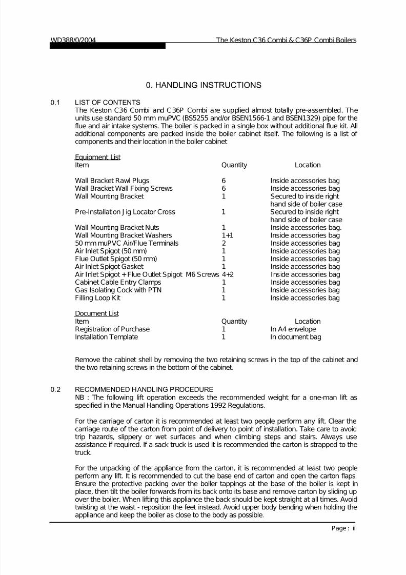
The Keston C36 Combi and C36P Combi are supplied almost totally pre-assembled. Theunits use standard 50 mm muPVC (BS5255 and/or BSEN1566-1 and BSEN1329) pipe for theflue and air intake systems. The boiler is packed in a single box without additional flue kit. Alladditional components are packed inside the boiler cabinet itself. The following is a list of components and their location in the boiler cabinet
Equipment ListItem Quantity Location
Wall Bracket Rawl Plugs 6 Inside accessories bagWall Bracket Wall Fixing Screws 6 Inside accessories bagWall Mounting Bracket 1 Secured to inside right
hand side of boiler casePre-Installation J ig Locator Cross 1 Secured to inside right
hand side of boiler caseWall Mounting Bracket Nuts 1 Inside accessories bag.Wall Mounting Bracket Washers 1+1 Inside accessories bag50 mm muPVC Air/Flue Terminals 2 Inside accessories bagAir Inlet Spigot (50 mm) 1 Inside accessories bagFlue Outlet Spigot (50 mm) 1 Inside accessories bagAir Inlet Spigot Gasket 1 Inside accessories bagAir Inlet Spigot +Flue Outlet Spigot M6 Screws 4+2 Inside accessories bagCabinet Cable Entry Clamps 1 Inside accessories bagGas Isolating Cock with PTN 1 Inside accessories bagFilling Loop Kit 1 Inside accessories bag
Document ListItem Quantity LocationRegistration of Purchase 1 In A4 envelopeInstallation Template 1 In document bag
Remove the cabinet shell by removing the two retaining screws in the top of the cabinet andthe two retaining screws in the bottom of the cabinet.
0.2 RECOMMENDED HANDLING PROCEDURE
NB : The following lift operation exceeds the recommended weight for a one-man lift as
specified in the Manual Handling Operations 1992 Regulations.
For the carriage of carton it is recommended at least two people perform any lift. Clear thecarriage route of the carton from point of delivery to point of installation. Take care to avoidtrip hazards, slippery or wet surfaces and when climbing steps and stairs. Always useassistance if required. If a sack truck is used it is recommended the carton is strapped to thetruck.
For the unpacking of the appliance from the carton, it is recommended at least two peopleperform any lift. It is recommended to cut the base end of carton and open the carton flaps.Ensure the protective packing over the boiler tappings at the base of the boiler is kept inplace, then tilt the boiler forwards from its back onto its base and remove carton by sliding upover the boiler. When lifting this appliance the back should be kept straight at all times. Avoidtwisting at the waist - reposition the feet instead. Avoid upper body bending when holding theappliance and keep the boiler as close to the body as possible.
WD388/0/2004 The Keston C36 Combi & C36P Combi Boilers
Page : iii

7/28/2019 C36 Combi Full Manual
http://slidepdf.com/reader/full/c36-combi-full-manual 5/56
Before hanging the appliance on the wall it is best to store the appliance laid on its back withthe casing on. When ready to hang the boiler on the wall remove the casing and place to oneside. At this stage it is assumed that the wall bracket is correctly positioned and secured onthe wall face.
a) Have the wall bracket nut and washer to hand so that they can be accessed whilstholding the boiler in position on its mounting bracket. If the optional pre-installation jig isnot being used discard the Pre-Installation J ig Locator Cross.
b) The boiler has a dry weight of 45 kg (99 lbs) and will therefore require at least two peopleto lift without the use of lifting aids - ensure co-ordinated movements durring lift. Alwaysuse assistance if required.
c) Lift the boiler by gripping at the four corners of the boiler back plate. When lifting thisappliance the back should be kept straight at all times. Avoid twisting at the waist -reposition the feet instead. Avoid upper body bending when holding the appliance andkeep the boiler as close to the body as possible.
d) Lift the boiler and locate onto the stud and the two pegs of the wall mounting bracket.e) Place the wall mounting bracket washers over the bracket stud protruding through the
back plate of the boiler.
f) Secure the boiler onto the wall bracket by fixing the wall mounting bracket nut onto thewall bracket stud. This must be tightened well.
Safety footwear and gloves are recommended PPE when lifting this appliance - to protectagainst sharp edges and ensure good grip.
The C36 Combi and C36P Combi boilers can be fitted in compartments with very smallclearances required around the appliance (refer to Section 3.1). Due consideration shouldtherefore be given to access within the compartment for lifting and positioning.
A pre-installation jig plate (part no C.10C.0.11.00.0) with heating flow, heating return and coldsupply isolation is available as an optional accessory. This jig enables the installation of thepipework to be carried out and pressure tested before hanging the boiler. Further instructions
for this procedure are included with the jig plate kit.
WD388/0/2004 The Keston C36 Combi & C36P Combi Boilers
Page : iv

7/28/2019 C36 Combi Full Manual
http://slidepdf.com/reader/full/c36-combi-full-manual 6/56
1. USER INSTRUCTIONS
1.1 INTRODUCTION Thank you for chosing this Keston C36 Combi for your household heating and hot waterneeds. The boiler is designed to be very straightforward to operate and has no userserviceable parts inside the cabinet. The following instructions are to provide you withinformation on the operation and maintenance of your C36 Combi and what to do in theunlikely event of a fault.
These user instructions should be read carefully to ensure safe and economical use of yourC36 Combi. The C36 Combi model is for use with natural gas only, the C36P Combi modelis for use with LPG only.
1.2 MAINTENANCEServicing To ensure continual safe and efficient operation and to maintain product warranties it is a
requirement that the appliance is checked and serviced at least once per year. It is the lawthat any servicing must be carried out by a competent person. Removal of the appliancecabinet by anyone other than a competent person will automatically invalidate theappliance warranty.
ClearancesIf fixtures are to be positioned close to the boiler, the following minimum clearances must beobserved: Top 150mm, Left 5mm, Right 5mm, Base 100mm, Front 305mm. Extendedclearance is required to the front for servicing.
CleaningNormal case cleaning only requires dusting with a dry cloth. To remove more stubborn markswipe with a damp cloth and finish with a dry cloth.
1.3 BOILER SETUP & OPERATIONCheck that the gas supply from the gas meter is turned on. Switch on the electrical supply tothe boiler. The display will now run through a self check procedure. Set any controls to call forheat.
To light the boiler The C36 Combi features separate adjustment of central heating and domestic hot watertemperature. To set these press the “+” or “-” buttons associated with the heating or hot watertemperature and set the required temperature. After a few seconds the display stop flashingand will change back to show the actual boiler temperature.If the actual temperature is less than the desired temperature the boiler will fire and, after afew seconds, a “.” will appear in the lower right hand corner of the display to show that the
boiler is alight.In summer you can switch the boiler to hot water only by pressing the “Summer” button tothat the green lamp above it is illuminated. In this mode the boiler will not respond to anydemand for central heating. Press the “Summer” button again to extinguish the green lightabove and resume normal central heating operation.
Normal OperationDuring normal operation the digital display will dhow the current boiler temperature and willshow a “.” In the lower right corner of the display when the burner is alight. If the green lampnear the CH or DHW+- keys is illuminated the boiler is receiving a demand for that function.If the green lamp is flashing the boiler is either up to temperature or shutting down followingremoval of the CH or DHW demand.
WD388/0/2004 Chapter 1 : User Instructions The Keston C36 Combi & C36P Combi Boilers
Installation & Servicing Instructions Page : 1

7/28/2019 C36 Combi Full Manual
http://slidepdf.com/reader/full/c36-combi-full-manual 7/56
Fault ModesIn the event that the boiler detects a situation which it considers to be a fault the display willchange to show a flashing fault code starting with an “E” and then a two digit number. Thetable below explains these codes and the action you should take.
Water pressure too high - You have put too much water pressure in your systemE40Water pressure error - You must top up the water pressure for your systemE37Mains supply frequency incorrect - There may be a problem with your power supply.E35Mains supply voltage <180V - There may be a problem with your power supplyE34
Flame drop out - Check for obstruction of the flue and/or air terminals,blockage/freezing of the drain pipe or a low gas supply (LPG).
E26
Water pressure losses - You have topped up the water pressure more than 4 times in24 hours. You may have a leak on the system..
E24
Boiler overheat - Check that any valves to the heating circuit have not been shut down,that there is no air in the system and that the water pressure is correct..
E03False flame - There is possibly a problem with the power supply.E02
Ignition failure - the boiler has attempted to light five times and not succeeded - check
the gas supply is on.
E01Descripti on of faultDisplay
The above is an abbreviate list of possible error codes. If the code is not in the list aboveconsult a CORGI registered engineer. A full list of codes can be found in Chapter 6 of thismanual. If a code appears and you feel the original cause has been rectified, press the“Reset” button to resume boiler operation. If the code persists consult a CORGI registeredengineer.When topping up the water pressure you can observe the actual pressure by pressing the“Installer” button repeatedly until the number “5” appears. After a few seconds the displaywith then change to show the system water pressure in bar. Set the water pressure tobetween 1.0 and 2.0 bar.
PrecautionsCare must be taken at all times to ensure that no blockage or obstruction is present in the
condensate drainage line. In addition, the air intake and flue exhaust terminals must be freefrom obstruction at all times.
Frost Protection The C36 Combi has an integral frost protection function. However, care should also be takenthat any exposed pipework is adequately insulated to prevent freezing.
1.4 SAFETY INFORMATION
IF YOU SUSPECT A GAS LEAK TURN OFF THE APPLIANCE IMMEDIATELY, TURN OFFTHE GAS TAP TO THE APPLIANCE (LOCATED UNDERNEATH) AND CONTACT YOURLOCAL GAS REGION WITHOUT DELAY.
Benchmark InitiativeAs part of the industry wide “Benchmark” initiative C36 Combi boilermanual includes Gas Boiler Commissioning Checklist (Chapter 10). This form should becompleted by your installer at the end of the installation and commissioning process. Thedetails of the Checklist will be required in the event of any warranty work being required. There is also Service Interval Record (Chapter 10) to be completed after each annualservice visit.
These forms (Chapter 10) should be kept in a safe place for the life of the boiler.
The boiler should be installed and serviced only by CORGI registered operatives. All CORGIregistered Installers carry a CORGI ID card and have a registration number. Both should berecorded in your boiler manual (Chapter 10: GAS BOILER COMMISSIONING
CHECKLIST). You can check your installer by calling CORGI direct on 01256 372300.
WD388/0/2004 Chapter 1 : User Instructions The Keston C36 Combi & C36P Combi Boilers
Installation & Servicing Instructions Page : 2
7/28/2019 C36 Combi Full Manual
http://slidepdf.com/reader/full/c36-combi-full-manual 8/56
2. GENERAL INSTRUCTION
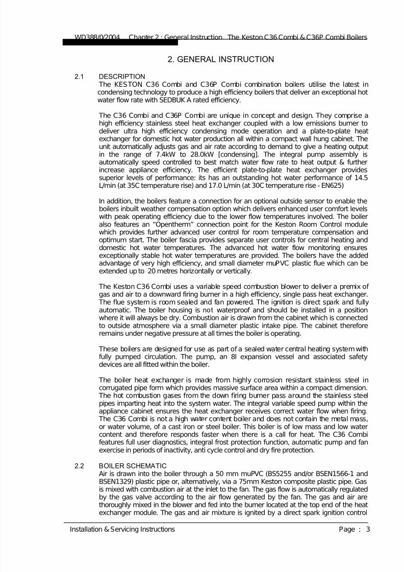
2.1 DESCRIPTION The KESTON C36 Combi and C36P Combi combination boilers utilise the latest incondensing technology to produce a high efficiency boilers that deliver an exceptional hot
water flow rate with SEDBUK A rated efficiency.
The C36 Combi and C36P Combi are unique in concept and design. They comprise ahigh efficiency stainless steel heat exchanger coupled with a low emissions burner todeliver ultra high efficiency condensing mode operation and a plate-to-plate heatexchanger for domestic hot water production all within a compact wall hung cabinet. Theunit automatically adjusts gas and air rate according to demand to give a heating outputin the range of 7.4kW to 28.0kW [condensing]. The integral pump assembly isautomatically speed controlled to best match water flow rate to heat output & furtherincrease appliance efficiency. The efficient plate-to-plate heat exchanger providessuperior levels of performance: its has an outstanding hot water performance of 14.5L/min (at 35C temperature rise) and 17.0 L/min (at 30C temperature rise - EN625)
In addition, the boilers feature a connection for an optional outside sensor to enable theboilers inbuilt weather compensation option which delivers enhanced user comfort levelswith peak operating efficiency due to the lower flow temperatures involved. The boileralso features an “Opentherm” connection point for the Keston Room Control modulewhich provides further advanced user control for room temperature compensation andoptimum start. The boiler fascia provides separate user controls for central heating anddomestic hot water temperatures. The advanced hot water flow monitoring ensuresexceptionally stable hot water temperatures are provided. The boilers have the addedadvantage of very high efficiency, and small diameter muPVC plastic flue which can beextended up to 20 metres horizontally or vertically.
The Keston C36 Combi uses a variable speed combustion blower to deliver a premix of gas and air to a downward firing burner in a high efficiency, single pass heat exchanger.
The flue system is room sealed and fan powered. The ignition is direct spark and fullyautomatic. The boiler housing is not waterproof and should be installed in a positionwhere it will always be dry. Combustion air is drawn from the cabinet which is connectedto outside atmosphere via a small diameter plastic intake pipe. The cabinet thereforeremains under negative pressure at all times the boiler is operating.
These boilers are designed for use as part of a sealed water central heating system withfully pumped circulation. The pump, an 8l expansion vessel and associated safetydevices are all fitted within the boiler.
The boiler heat exchanger is made from highly corrosion resistant stainless steel incorrugated pipe form which provides massive surface area within a compact dimension. The hot combustion gases from the down firing burner pass around the stainless steel
pipes imparting heat into the system water. The integral variable speed pump within theappliance cabinet ensures the heat exchanger receives correct water flow when firing. The C36 Combi is not a high water content boiler and does not contain the metal mass,or water volume, of a cast iron or steel boiler. This boiler is of low mass and low watercontent and therefore responds faster when there is a call for heat. The C36 Combifeatures full user diagnostics, integral frost protection function, automatic pump and fanexercise in periods of inactivity, anti cycle control and dry fire protection.
2.2 BOILER SCHEMATICAir is drawn into the boiler through a 50 mm muPVC (BS5255 and/or BSEN1566-1 andBSEN1329) plastic pipe or, alternatively, via a 75mm Keston composite plastic pipe. Gasis mixed with combustion air at the inlet to the fan. The gas flow is automatically regulatedby the gas valve according to the air flow generated by the fan. The gas and air arethoroughly mixed in the blower and fed into the burner located at the top end of the heatexchanger module. The gas and air mixture is ignited by a direct spark ignition control
WD388/0/2004 Chapter 2 : General Instruction The Keston C36 Combi & C36P Combi Boilers
Installation & Servicing Instructions Page : 3
7/28/2019 C36 Combi Full Manual
http://slidepdf.com/reader/full/c36-combi-full-manual 9/56
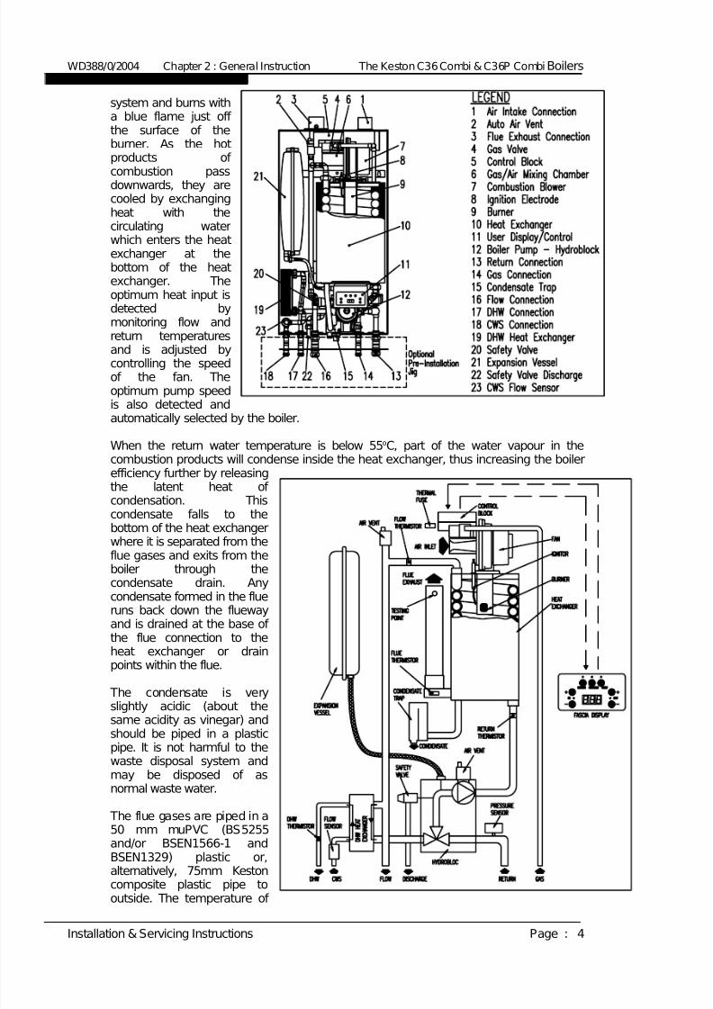
system and burns witha blue flame just off the surface of theburner. As the hotproducts of
combustion passdownwards, they arecooled by exchangingheat with thecirculating waterwhich enters the heatexchanger at thebottom of the heatexchanger. Theoptimum heat input isdetected bymonitoring flow andreturn temperatures
and is adjusted bycontrolling the speedof the fan. Theoptimum pump speedis also detected andautomatically selected by the boiler.
When the return water temperature is below 55oC, part of the water vapour in thecombustion products will condense inside the heat exchanger, thus increasing the boilerefficiency further by releasingthe latent heat of condensation. Thiscondensate falls to the
bottom of the heat exchangerwhere it is separated from theflue gases and exits from theboiler through thecondensate drain. Anycondensate formed in the flueruns back down the fluewayand is drained at the base of the flue connection to theheat exchanger or drainpoints within the flue.
The condensate is very
slightly acidic (about thesame acidity as vinegar) andshould be piped in a plasticpipe. It is not harmful to thewaste disposal system andmay be disposed of asnormal waste water.
The flue gases are piped in a50 mm muPVC (BS5255and/or BSEN1566-1 andBSEN1329) plastic or,alternatively, 75mm Keston
composite plastic pipe tooutside. The temperature of
WD388/0/2004 Chapter 2 : General Instruction The Keston C36 Combi & C36P Combi Boilers
Installation & Servicing Instructions Page : 4

7/28/2019 C36 Combi Full Manual
http://slidepdf.com/reader/full/c36-combi-full-manual 10/56
the flue gases are usually around 5oC to 10oC above the temperature of the return water. The flue pipe should be terminated outside the building from where they cannot re-enterthe building or any other adjacent building.
The heating level may be controlled by room thermostats, programmer time clocks and
compatible energy management systems. An optional Keston room controller can beconnected which will provide enhanced controls such as room compensation to furtherincrease efficiency and comfort levels. Once the controls are set the boiler operatesautomatically. Further, a Keston outside sensor can be connected to the boiler which willautomatically invoke weather compensated heating which further boosts user comfortand boiler efficiency.
In the event of the boiler overheating the safety devices will cause a safety shutdown. Asafety discharge valve and discharge pipe is fitted to the boiler.
The C36 Combi features an integral frost protection function which will operate the pump,regardless of the external controls, should the boiler temperature fall below 10oC. In theevent the boiler temperature falls below 5oC the boiler will also fire. This is to avoid
damage to the boiler through freezing of boiler water. The boiler will turn off when the flowtemperature exceeds 15oC. The C36 Combi features an integral pump exercise function which will run the pump,without firing the boiler, for 10 seconds in the event the boiler is on standby for in excessof 24 hours without firing. This is to help prevent seizing of the pump due to long periodsof inactivity.
2.3 RELATED DOCUMENTS The Keston C36 Combi and C36P Combi Combination Condensing Boiler must beinstalled in accordance with the current issue of the Gas Safety (Installation and Use)Regulations 1996, current IEE Wiring Regulations, Building Regulations, BuildingStandards (Scotland) Consolidation, and the Bye Laws of the local Water Undertaking. It
is the law that ALL gas appliances are installed by a competent person in accordancewith the above regulations.
In addition, due account must be taken to the following Codes Of Practice:BS 6891 : Gas SuppliesBS 6798 : Installation Central Heating BoilersBS 5449 : Installation Pumped Central HeatingBS 5546 : Installation Domestic Hot Water BS 5440.1 : FluesBS 5440.2 : Air SupplyBS 5482.1 : Domestic Propane and Butane Burning
InstallationsBS 7074.1 : Expansion Vessels
BS 7593 : Treatment of Water in Hot Water Central HeatingSystems
BS 7671 : Requirements for Electrical Installations. IEEWiring Regulations 16th Edition.
For Timber Framed Buildings, British Gas Publications DM2. Also British GasPublications 'Guidance Notes For The Installation Of Domestic Gas CondensingBoilers' and 'Specification For Domestic Wet Central Heating Systems'.
In IE, the installation must be carried out by a competent person and installed inaccordance with the current edition of IS813 “Domestic Gas Installations”, the currentBuilding Regulation and reference should be made to the current ETC1 rules for electricalinstallations.
WD388/0/2004 Chapter 2 : General Instruction The Keston C36 Combi & C36P Combi Boilers
Installation & Servicing Instructions Page : 5
7/28/2019 C36 Combi Full Manual
http://slidepdf.com/reader/full/c36-combi-full-manual 11/56
No alterations should be made to the boiler without written permission from KestonBoilers Ltd. Any unauthorised modification will invalidate the warranty and may affect thesafe and efficient operation of the boiler.
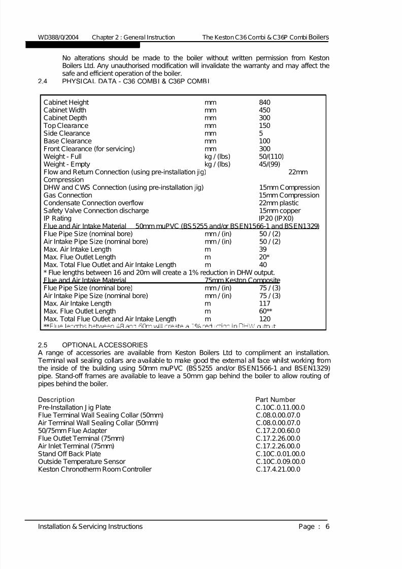
2.4 PHYSICAL DATA - C36 COMBI & C36P COMBI
Cabinet Height mm 840Cabinet Width mm 450Cabinet Depth mm 300 Top Clearance mm 150Side Clearance mm 5Base Clearance mm 100Front Clearance (for servicing) mm 300Weight - Full kg / (lbs) 50/(110)Weight - Empty kg / (lbs) 45/(99)Flow and Return Connection (using pre-installation jig) 22mmCompressionDHW and CWS Connection (using pre-installation jig) 15mm CompressionGas Connection 15mm CompressionCondensate Connection overflow 22mm plasticSafety Valve Connection discharge 15mm copperIP Rating IP20 (IPX0)Flue and Air Intake Material 50mm muPVC (BS5255 and/or BSEN1566-1 and BSEN1329)Flue Pipe Size (nominal bore) mm / (in) 50 / (2)Air Intake Pipe Size (nominal bore) mm / (in) 50 / (2)Max. Air Intake Length m 39Max. Flue Outlet Length m 20*Max. Total Flue Outlet and Air Intake Length m 40* Flue lengths between 16 and 20m will create a 1% reduction in DHW output.Flue and Air Intake Material 75mm Keston CompositeFlue Pipe Size (nominal bore) mm / (in) 75 / (3)
Air Intake Pipe Size (nominal bore) mm / (in) 75 / (3)Max. Air Intake Length m 117Max. Flue Outlet Length m 60**Max. Total Flue Outlet and Air Intake Length m 120**
2.5 OPTIONAL ACCESSORIESA range of accessories are available from Keston Boilers Ltd to compliment an installation. Terminal wall sealing collars are available to make good the external all face whilst working fromthe inside of the building using 50mm muPVC (BS5255 and/or BSEN1566-1 and BSEN1329)pipe. Stand-off frames are available to leave a 50mm gap behind the boiler to allow routing of pipes behind the boiler.
Description Part Number Pre-Installation J ig Plate C.10C.0.11.00.0Flue Terminal Wall Sealing Collar (50mm) C.08.0.00.07.0Air Terminal Wall Sealing Collar (50mm) C.08.0.00.07.050/75mm Flue Adapter C.17.2.00.60.0Flue Outlet Terminal (75mm) C.17.2.26.00.0Air Inlet Terminal (75mm) C.17.2.26.00.0Stand Off Back Plate C.10C.0.01.00.0Outside Temperature Sensor C.10C.0.09.00.0Keston Chronotherm Room Controller C.17.4.21.00.0
WD388/0/2004 Chapter 2 : General Instruction The Keston C36 Combi & C36P Combi Boilers
Installation & Servicing Instructions Page : 6

7/28/2019 C36 Combi Full Manual
http://slidepdf.com/reader/full/c36-combi-full-manual 12/56
2.6 PERFORMANCE DATA - C36 COMBI & C36P COMBI
Seasonal Efficiency (SEDBUK) =90.7 (C36 Combi) & 92.8 (C36P Combi)This value is used in the UK Government's Standard Assessment Procedure (SAP) for energy rating of dwellings. The test data from which it has been calculated have beencertified by Advantica Technologies Ltd
Keston Boilers Ltd declare that there are no substances harmful to health within theappliance or used during the production of the appliance.
The C36 Combi is intended for domestic and commercial EMC environments and on agoverned G20 meter supply.
WD388/0/2004 Chapter 2 : General Instruction The Keston C36 Combi & C36P Combi Boilers
Installation & Servicing Instructions Page : 7
C36 COMBI C36P COMBINat. Gas (G20) LPG (G31)
Min. Input (Gross CV) kW/(Btu/h) 8.3/(28,300) 8.1/(27,600)Max. CH Input (Gross CV) kW/(Btu/h) 28.3/(96,500) 27.7/(94,500)Max. DHW Input (Gross CV) kW (Btu/h) 40.0/(136,500) 39.0/(133,000)Max. DHW Output to Water kW/(Btu/h) 36.0/((122,800) 36.0/(122,800)Max. CH Output To Water
(80/60oC Flow/Return) kW/(Btu/h) 25.2/(86,000) 25.2/(86,000)(50/30oC Flow/Return) kW/(Btu/h) 28.0/(95,500) 27.7/(94,500)
Min. CH Output To Water
(80/60oC Flow/Return) kW/(Btu/h) 7.4/(25,250) 7.4(25,250)(50/30oC Flow/Return) kW/(Btu/h) 8.2/(28,000) 8.1/(27,600)
Max. Domestic Hot Water Flow Rate litre/min 14.5 14.5(at 35OC Rise)
Specific DHW Rate (30OC Rise) litre/min 17.0 17.0Min. Domestic Hot Water Flow Rate litre/min 0.35 0.35Max. Domestic Hot Water Flow Temp. OC 65 65Max. Burner Press.-Hot (Factory Preset) mbar/(in w.g) 0/(0) 0/(0)Max. Gas Cons. After 10 mins (DHW) l/s / (Ft3/hr) 1.03/(131) 0.48/(61)Max. Operating Flow Temp. oC 82 82Max. Press. (Sealed System) bar 2.50 2.50Inlet Gas Pressure mbar/(in w.g) 20.0 / (8.0) 37.0/(14.8)
Recommended Temp Diff. oC 8 to 20 8 to 20Electrical Supply 230V 50Hz 230V 50Hz
Power Consumption (Max) W 180 180Power Consumption (Standby) W 6 6 Type of Gas G20 Natural Gas G31 LPGOptimum Flue Gas CO2 Level (at max CH rate, case on) 9.3 10.6Expected CO/CO2 Ratio (at max CH rate, case on) 0.0006 0.001Destination Countries GB/IE GB/IESEDBUK Efficiency 90.7 92.8NOx Class 5 5Safety Valve bar / (lbf/sq in) 3 / (43.5) 3 / (43.5)Expansion Vessel Capacity litre 8 8[NB: For larger systems an additional expansion vessel may be required]Expansion Vessel Charge Pressure bar / (lbf/sq in) 1.0 / (14.5)Heating System Minimum Pressure bar / (lbf/sq in) 0.6 / ( 8.7)
DHW Max. Working Pressure bar / (lbf/sq in) 8/ (116)Min. Working Pressure for Max. Domestic Flow Rate bar / (lbf/sq in) 2MaximumCWS InletTem erature oC 50 50

7/28/2019 C36 Combi Full Manual
http://slidepdf.com/reader/full/c36-combi-full-manual 13/56
The C36P Combi is intended for domestic and commercial EMC environments and on agoverned G31 supply.
This boiler meets the requirements of SI 3083 The Boiler (Efficiency) Regulations and is thereforedeemed to meet the requirements of Directive 92/42/EEC. The CE mark on the appliance shows
compliance with Directives 90/396/EEC, 73/23/EEC and 89/336/EEC.
IMPORTANTThis product contains ceramic fibre boards, which although not regarded as a risk, containceramic f ibre which may cause temporary irritation to eyes, skin and respiratory tract. Thefibres are held in place by inorganic binders. Therefore as long as the boards are notdisturbed they will not be released. Since the boards are non-servicable parts there shouldbe no risk . Under no c ircumstances shou ld the user interfere with any sealed parts.
To ensure that the release of fibres from these RCF articles is kept to a minimum, duringinstallation and servicing we recommend that you use a HEPA fil tered vacuum to removeany dust accumulated in and around the appliance before and after working on the appli-ance. When replacing these articles we recommend that the replaced items are not
broken up, but are sealed within heavy duty polythene bags, and clearly labelled as RCFwaste. RCF waste is classed as a stable, non-reactive hazardous waste and may bedisposed at a landfill licensed to accept such waste. Protective clothing is not requiredwhen handling these articles, but we recommend you follow thenormal hygiene rules of not smoking, eating or drinking in thework area and always wash your hands before eating or dri nking.
Benchmark InitiativeAs part of the industry wide “Benchmark” initiative C36 Combi boiler manual includes Gas Boiler Commissioning Checklist (Chapter 10). This form should be completed by your installer at theend of the installation and commissioning process. The details of the Checklist will be required inthe event of any warranty work being required. There is also Service Interval Record (Chapter
10) to be completed after each annual service visit.
These forms (Chapter 10) should be kept in a safe place for the life of the boiler.
The boiler should be installed and serviced only by CORGI registered operatives. All CORGIregistered Installers carry a CORGI ID card and have a registration number. Both should berecorded in your boiler manual (Chapter 10: GAS BOILER COMMISSIONING CHECKLIST). You can check your installer by calling CORGI direct on 01256 372300.
WD388/0/2004 Chapter 2 : General Instruction The Keston C36 Combi & C36P Combi Boilers
Installation & Servicing Instructions Page : 8
IN THE EVENT OF A GAS LEAK Turn off the gas isolation valve to the property immediately. Extinguishall naked flames or other sources of ignition. Do not operate electricalswitches on or off. Open all doors and windows to ventilate the area.

7/28/2019 C36 Combi Full Manual
http://slidepdf.com/reader/full/c36-combi-full-manual 14/56
3. BOILER LOCATION
3.1 DIMENSIONS AND MINIMUM
CLEARANCES The boiler must be installed in minimumclearances shown to allow subsequentservicing, and safe operation. However, largerclearances may be required duringinstallation.
3.2 SERVICE CONNECTIONSWithout Optional Pre-Installation J ig:Gas, water, air and flue pipe, condensation,and electrical connections are as shown. Gas: 15mm compression. Flow/Return 0.75BSPMcompression. DHW/CWS 0.5BSPM
compression.With Optional Pre-Installation J ig:Gas, water, air and flue pipe, condensation,and electrical connections are as shown.Gas : 15mm compression. Flow/Return22mm compression. DHW/CWS 15mmcompression.
An optional stand-off frame is also availablewhich mounts behind the boiler to leave a50mm deep space behind the boiler. This isto permit pipe routing behind the boiler if required. See Section 2.5 - Optional
Accessories. 3.3 POSITION
The C36 Combi and C36P Combi are notsuitable for external installation. The boilermay be installed in any room or internalspace, although particular attention is drawnto the requirements of the current IEE WiringRegulations and, in Scotland, the electricalprovisions of the Building Regulations
WD388/0/2004 Chapter 3 - Boiler Location The Keston C36 Combi & C36P Combi Boilers
Installation & Servicing Instructions Page : 9
All dimensions in mm.
150
300 When servicing appliance
100Figure 3.1.1
Minimum Clearances
55
10 When appliance is operating
All dimensio
450 3 0 0
Figure 3.1.2Dimensions
Flue
Air Intake
8 4
0

7/28/2019 C36 Combi Full Manual
http://slidepdf.com/reader/full/c36-combi-full-manual 15/56
applicable in Scotland, with respect to the installation of the boiler in a room or internalspace containing a bath or shower.Where a room-sealed appliance is installed in a room containing a bath or shower, anyelectrical switch or appliance control, utilising mains electricity, should be so situated thatit cannot be touched by a person using the bath or shower. The C36 Combi and C36P
Combi are classified as IP20 (IPX0) and are therefore suitable for installation in Zone 3areas, unless subject to hose down.Compartment installation is permitted - such compartments must be constructed inaccordance with BS 6798. The wall on which the boiler is mounted must be of suitable load bearing capacity andmust be non-combustible. The Keston C36 Combi can be located virtually anywhere desired provided that all
regulations are complied with. Because of the boiler's compact size and venting flexibility,the installation is not limited to a boiler room setting. Before locating the boiler near aliving space consider whether the sounds generated by the boiler will be objectionable. The boiler may be located within a cupboard enclosure to reduce noise levels if located
within a living space. LPG boilers must not be installed in a cellar.
3.4 ELECTRICAL
3.4.1 Electrical Connections The boiler must be connected to a permanent 230V ~50Hz supply, fused at 3A.The boiler has provision to receive a 230VAC switched live signal from aroom thermostat/time clock. Alternatively, a Keston Room Controller can beconnected directly, via two core low voltage cable, to the terminals marked“ OT” . The Keston Room Controller will then provide fully roomcompensated control to ensure the boiler output is matched to the roomsrequirements at optimum boiler efficiency. DHW demand will always takepriority over heating demand. Wiring external to the boiler must be in
accordance with current I.E.E wiring regulations and local regulations.
WD388/0/2004 Chapter 3 - Boiler Location The Keston C36 & C36P Combi Boilers
Installation & Servicing Instructions Page : 10
Chimneys not used for
venting any other
appliance may be used.
Figure 3.3
Secure air & flue pipes at
chimney outlet.
[NB: Refer to
Section 3.8.3]

7/28/2019 C36 Combi Full Manual
http://slidepdf.com/reader/full/c36-combi-full-manual 16/56
The method of connection to the mains electricity supply must facilitate completeelectrical isolation of the boiler, preferably by the use of a fused, unswitchedthree pin plug and a shuttered socket-outlet, both complying with therequirements of BS 1363. There must be only one common method of isolationfor the boiler and its control system.
The appliance must be connected to the 3A supply via a fused double-poleswitch having at least 3 mm (1/8 inch) contact separation in both poles, servingonly the boiler and the system controls. The connection point to the mains supply should be readily accessible andadjacent to the boiler, except for rooms containing a bath or a shower. Refer tosection 3.3 Position.
3.4.2 External Wiring & Controls1. The boiler is designed so that all control wiring is external to the boiler.2. Heating control signal inputs must the 230VAC "switched live" type
unless using a Keston Room Controller (see below)
3.4.2.1 Enhanced Contro l OptionsRoom Compensation (Opentherm)A Keston Room Controller may be used to provide room compensatedcontrol to ensure the boiler output is matched to the rooms requirementsat optimum boiler efficiency
Weather CompensationA Keston outside temperature sensor may be connected as an option. The boiler will automatically detect this connection and will operate on a"weather compensation" basis when receiving a heating demand signalfrom the SL terminal or from a Keston Room Controller. Screened cable(80% density) must be used to connect the outside temperature sensor.
3.5 BOILER SIZE SELECTION The C36 Combi will automatically adjust heat output and pump speed to match thesystem requirements at any given time. Efficiency and combustion levels are maintainedat optimum levels throughout the possible output range. The C36 Combi is thereforesuitable for all systems with a total heat load within the maximum range of the boiler.
3.6 GAS SUPPLYA gas meter should be connected to the service pipe by the local gas region or theircontractor. An existing meter should be checked preferably by the gas region to ensurethat the meter is adequate to deal with the rate of gas supply required. Installation pipesshould be fitted in accordance with BS 6891.Minimum/Maximum Gas Pressure:Natural gas pressure before the gas valve must be maintained at between 18 mbar (7.2
in WG) and 22 mbar (8.8 in) while the boiler is running.
WD388/0/2004 Chapter 3 - Boiler Location The Keston C36 Combi & C36P Combi Boilers
Installation & Servicing Instructions Page : 11
Live
Neutral
Earth
Mains Supply
230VFused @ 3A
Room Thermostat
T6360B1028
1
23
KESTON
C36 Combi
LN
E
SL
3.4.2 Wiring Example
OTC
OTC
To KestonExt. Sensor[Optional]
OT
OT
To KestonRoom Controller
[Optional - instead of room thermostat]
7/28/2019 C36 Combi Full Manual
http://slidepdf.com/reader/full/c36-combi-full-manual 17/56
LPG pressure must be maintained between 31.5 mbar (12.4 in w.g) and 37.6 mbar (14.8in w.g) while the boiler is running.Gas pressures above or below these levels will lead to problems associated with the gasvalve's internal pressure regulator.Supply pipes to the boiler must not be sized less than the boiler inlet connection
(15 mm). Due consideration must be given to the supply pressure to other gasappliances in the premises. Reduction in dynamic gas supply pressure will resultin intermittent ignition failures. Ensure gas supply pipe work is adequately sizedfor the length of run from the meter to the boiler at a supply rate of 40kW (i.e. anatural gas supply should be considered to be a minimum of 22mm diameter, reducing to15mm at the boiler. If gas runs greater than 12m, including the allowance for bends, areinvolved the pipe size should be increased further).
3.7 CH & DHW WATER SYSTEMSAll piping must be installed in accordance with all applicable local and Water SupplyBylaws for forced hot water heating systems.Consideration must be given to pipe capabilities and pressure drop through the pipingwhen selecting pipe sizes. The primary pipe connections to the boiler must be sized
according to the system load, not dictated by the boiler connection sizes.Water treatment must be carried out to BS 7593 : Treatment of Water in Hot WaterCentral Heating Systems.In IE the requirements given in the current edition of IS813 and the current BuildingRegulations must be followed.
a The Keston C36 Combi is designed for installation on sealed water systems only.With fully pumped water circulation. The pump, an 8l expansion vessel andassociated safety devices are fitted within the boiler.
b Any system must be thoroughly flushed clean of grease, dirt and debris, prior toconnection with the boiler. A trap may be installed in the flow line to collect anysolder, or other debris, from the installation.
c All water systems must be constructed to comply with requirements of the Local
Water Authority.d Always use a system complying with the requirements of BS 5449 and BS 6798.e System design must ensure an open circuit is always available to ensure
circulation when the pump overrun function is operating after boiler shutdown.f Isolation valves must be fitted on the cold mains supply, the heating flow and the
heating return to enable isolation when maintaining the boiler. Such isolationvalves are included in the optional pre-installation jig (C.10C.0.11.00.0)
g Copper tubing to BS 2871 Part 1 or barrier plastic pipe suitable to 110oC, suchas Unipipe, is recommended.
h J ointing should be either with capillary, threaded or compression fittings. Pipesshould have a gradient to ensure air is passed easily to vent points and waterflows readily to drain points.
i Draining taps must be located in accessible positions which permit the draining of
the boiler. Draining taps should be at least 22 mm in nominal size and be inaccordance with BS 2879. A drain tap is incorporated into the optionalpre-installation jig (C.10C.0.11.00.0)AIR VENT POINTS
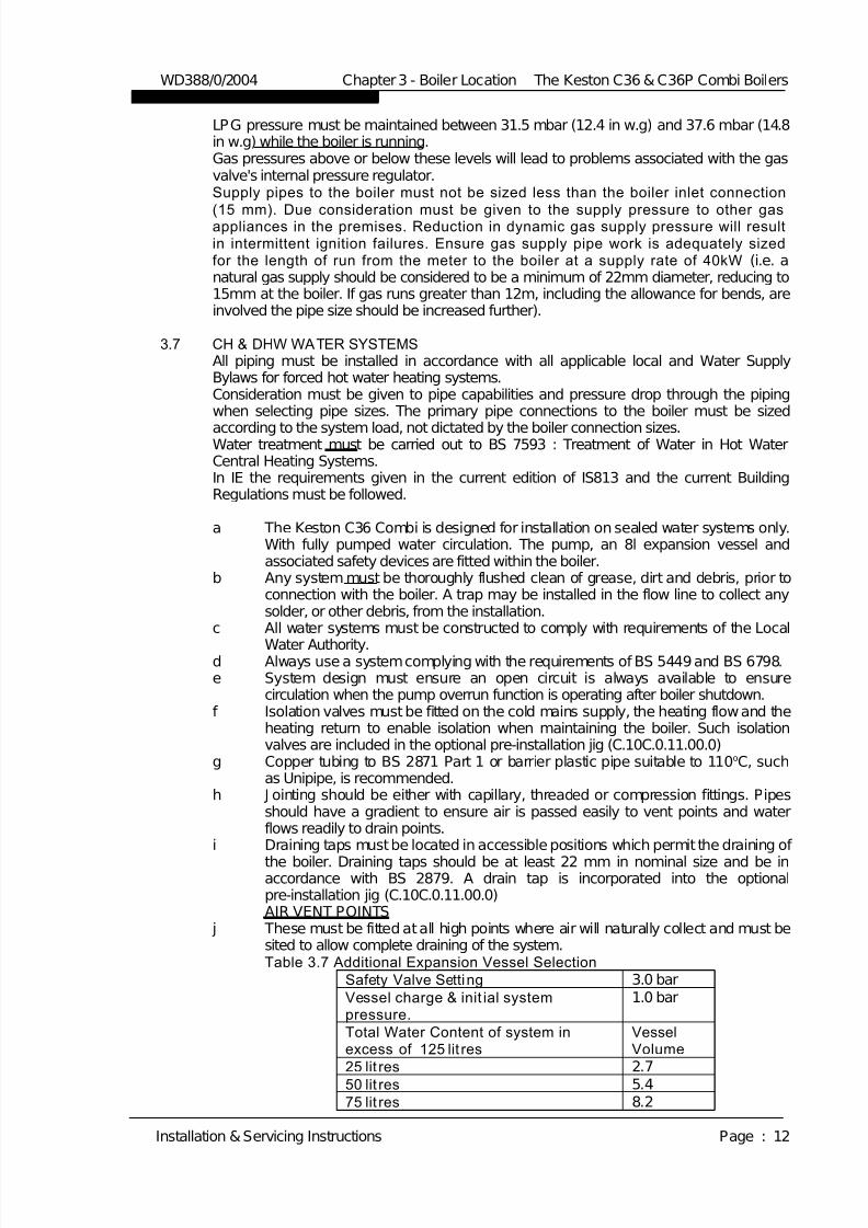
j These must be fitted at all high points where air will naturally collect and must besited to allow complete draining of the system.Table 3.7 Additional Expansion Vessel Selection
8.275 lit res
5.450 lit res
2.725 lit res
VesselVolume
Total Water Content of system inexcess of 125 lit res
1.0 barVessel charge & init ial systempressure.
3.0 barSafety Valve Setting
WD388/0/2004 Chapter 3 - Boiler Location The Keston C36 & C36P Combi Boilers
Installation & Servicing Instructions Page : 12

7/28/2019 C36 Combi Full Manual
http://slidepdf.com/reader/full/c36-combi-full-manual 18/56
13.6125 lit res
10.9100 lit res
k. The boiler is supplied with an integral expansion vessel of 8l capacity. This issuitable for systems of up to 125 Litres system volume. Table 3.7 Expansion
Vessel Selection provides guidance for the correct additional expansion vesselsize to use for systems with a water content larger than 125 Litres. Any additionalvessel must be fitted on the boiler primary return.
l A filling point must be fitted, in accordance with local water authorityrequirements. An approved filling loop is supplied loose with the boiler installation jig. There must be no permanent connection to the mains water supply. The fillingloop must therefore be left isolated at both ends and disconnected after thesystem is filled.
m The installation must be designed to work with flow temperatures of up to 110 oC.All components of the system must be suitable for a working pressure of 3 barand a temperature of 110 oC. Care should be taken in making all connections thatthe risk of leakage is minimised.
n The pipe from the safety discharge valve must not discharge above an entrance,
windowor any type of public access area. The boiler safety discharge valve pipemust be extended using not less than 15mm pipe to discharge, in a visibleposition, outside the building, facing downwards, preferably over a drain. Thepipe must have a continuos fall and be routed to a position so that any dischargeof water, possibly boiling, or steam cannot create any danger to persons,damage to property or external electrical components or wiring. To ease future
servicing it is advisable to use a compression type fitting to extend the safetydischarge valve pipe.
3.7.1 Boiler By-pass PipingBoiler water flows are critical to the operation of the boiler. If flow cannot be maintainedthrough the system piping to meet the minimums required by the boiler, insufficient waterflows through the boiler will cause the boiler to "kettle" or even produce steam which candamage the heat exchanger and will invalidate the heat exchanger warranty. In addition,an open circuit is required after boiler shutdown to permit circulation during the boilers 2minute pump overrun sequence.It is advisable to incorporate a boiler by-pass in the system, especially if thermostaticradiator valves are used. The flow/return differential should be 10oC to 20oC. To complywith the Building Regulations Part L1 the bypass must of the automatic type.
3.7.2 Air El iminat ion
WD388/0/2004 Chapter 3 - Boiler Location The Keston C36 Combi & C36P Combi Boilers
Installation & Servicing Instructions Page : 13
COMBIKESTON
Expansion
Isolating Valve
HEATING CIRCUIT
FLOW
RETURN
(disconnected
after filling)
Flex Hose
Isolating & Dbl Chekc Valve
By-pass(if required)
DrainCock
(if required) D O M E S T I C W A T E R
D O M E S T I C H O T W A T E R
C O
L D W A T E R S U P P L Y
Vessel
Figure 3.7 : CH & DHW Sealed Systems Diagram

7/28/2019 C36 Combi Full Manual
http://slidepdf.com/reader/full/c36-combi-full-manual 19/56
In the initial charge of water tothe boiler system and in allsubsequent additions of waterto the system some air will bedissolved in the water. As the
water is heated the air is drivenout of the solution and willcollect in high spots in thesystem. These air bubbles caninterfere with pumping andheat transfer and must beeliminated.Installation of air bleed valves atthe high spot(s) in the systemwill allow for air eliminationwhen filling the system and willallow re-venting in a day or soafter all air has been driven out
of solution.
3.7.3 System PumpSelection (if required)
The C36 Combi features anintegral circulating pump whichhas sufficient excess head todrive most domestic systems. The available head isshown in the graphbelow. If the systemindex circuit resistanceis in excess of the
available head from theintegral pump anadditional system pumpwill be required.
The schematic belowillustrates arecommended approachto using an additionalsystem pump. Theadditional system pumpshould be sized toovercome the index
circuit resistance only asthe boilers integral pumpwill overcome boiler resistance.
If an additional pump is required the selected pump must comply with BS 1394. Provisionmust be made in the system design for control of the additional pump.
3.7.4 Filling The System The boiler is supplied with an approved filling loop device. This filling device is designedto enable initial fill and topping up of system pressure. The system should be set to apressure of between 1.0 and 1.5 bar. To display the system water pressure press the“Installer” button, on the boiler fascia, repeatedly until the number 5 appears on the
display. After a few seconds the display will change to show the water pressure, in bars.Using the filling loop set the pressure to 1.0 to 1.5 bar,
WD388/0/2004 Chapter 3 - Boiler Location The Keston C36 & C36P Combi Boilers
Installation & Servicing Instructions Page : 14
Additional SystemPump(if required)
C O L D W A T E R S U P P
L Y
D O M E S T I C H O T W A T E R
D O M E S
T I C W A T E R
(if required)
COMBI
HEATING CIRCUIT
KESTON
ExpansionVessel
DrainCock
RETURN
FLOW
PermanentlyOpen 28mmBy-pass
C36 Combi Available pump head
0
1
2
3
4
5
6
7
0 5 10 1 5 20 25 30 35 40
F l o w Ra t e ( l p m )
7/28/2019 C36 Combi Full Manual
http://slidepdf.com/reader/full/c36-combi-full-manual 20/56
3.8 FLUE SYSTEMNB: When installing a replacement boiler a new flue system must be used. Do
not re-use the existing boiler flue installation.
3.8.1 Design
Individual air supply and flue outlet pipes are used. The material used for flue outlet &/orair inlet must be muPVC to BS 5255 and/or BSEN1566-1 and BSEN1329 of an internaldiameter of 51 mm. (i.e. nominal 50 mm diameter muPVC solvent weld waste pipe)
Alternatively, where flue or air intake lengths of up to 60m are require, Keston Composite75mm flue and air pipe can be used (contact your Keston stockist for details). KestonComposite 75mm pipe MUST be painted where exposed to UV light.
Both 50mm flue outlet terminal and 50mm air inlet terminal are supplied and areillustrated in Figure 3.8.1. Both terminals are identical. If 75mm terminals are requiredthese can be obtained from your Keston Boilers stockist. Request part numbersC.17.2.26.00.0 (terminals) and C.17.2.00.60.0 (50 to 75 adapters).
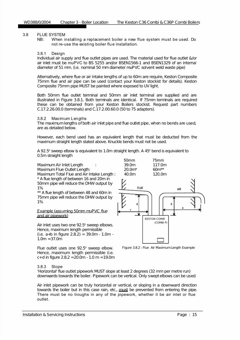
3.8.2 Maximum Lengths The maximum lengths of both air inlet pipe and flue outlet pipe, when no bends are used,are as detailed below.
However, each bend used has an equivalent length that must be deducted from themaximum straight length stated above. Knuckle bends must not be used.
A 92.5o sweep elbow is equivalent to 1.0m straight length. A 45o bend is equivalent to0.5m straight length
50mm 75mmMaximum Air Inlet Length : 39.0m 117.0mMaximum Flue Outlet Length: 20.0m* 60m**Maximum Total Flue and Air Intake Length : 40.0m 120.0m
* A flue length of between 16 and 20m in50mm pipe will reduce the DHW output by1%** A flue length of between 48 and 60m in75mm pipe will reduce the DHW output by1%
Example (assuming 50mm muPVC flueand air pipework)
Air inlet uses two one 92.5o sweep elbows.Hence, maximum length permissible(i.e. a+b in figure 2.8.2) = 39.0m - 1.0m -
1.0m =37.0m
Flue outlet uses one 92.5o sweep elbow.Hence, maximum length permissible (i.e.c+d in figure 2.8.2 =20.0m - 1.0 m =19.0m
3.8.3 Slope‘Horizontal' flue outlet pipework MUST slope at least 2 degrees (32 mm per metre run)downwards towards the boiler. Pipework can be vertical. Only swept elbows can be used.
Air inlet pipework can be truly horizontal or vertical, or sloping in a downward directiontowards the boiler but in this case rain, etc., must be prevented from entering the pipe.There must be no troughs in any of the pipework, whether it be air inlet or flue
outlet.
WD388/0/2004 Chapter 3 - Boiler Location The Keston C36 Combi & C36P Combi Boilers
Installation & Servicing Instructions Page : 15
AIRFLUE
abd
c
Figure 3.8.2 : Flue Air Maximum Length Example
KESTON COMBI
(COMBI P)

7/28/2019 C36 Combi Full Manual
http://slidepdf.com/reader/full/c36-combi-full-manual 21/56
Due the low temperature of the flue gases furthercondensate will form within the flue system. Drainpoints, with suitable traps, must therefore beincorporated within the flue system at the base of vertical flue sections in excess of 6m, for 50mm
muPVC pipe flue systems. These additionalcondensate drains must be run to discharge asdetailed in section 3.11. Such drain points can beformed using standard muPVC fittings. Refer to
the example in Figure 3.8.3.
3.8.4 Terminat ions Air inlet terminals must be facing horizontally ordownwards to prevent entry of rain into theterminal and positioned to ensure only fresh air isdrawn into the boiler. The air terminal must belocated outside of the building.Drawing of combustion air directly from a
ventilated boiler room invalidates the heatexchanger warranty. The flue outlet terminal is designed to face outwardsbut can, if desired, be adapted to face in anydirection BUT must not be directed in the region of the air inlet. The flue terminal and air inlet terminalcan be located on different, but not opposing wallfaces. The two terminals are subject to the requirements of BS 5440 Pt 1 for clearances from features of thebuilding although some can be decreased to thevalues indicated.The Keston C36 Combi and C36P Combi, as with any condensing boiler, will
generate a condensate “plume” from the flue terminal in all weather conditions.Consideration must therefore be given to the effect of this “ plume” when selectinga location for the flue terminal. It is the responsibility of the installer to ensure theselected terminal location does not cause nuisance.
300300L Horizontally from terminal on same wall.
1,5001,500K Vertically from terminal on same wall.
1001,200 J From opening in a car port.(not recommended)
1,2001,200I From terminal facing a terminal.
100600H From surface facing a terminal *
100200G Above ground or balcony or roof.
50200F From internal or external corner.
5075E From vertical drain or soil pipes.50200D Below balconies or car port roof.
50200C Below eaves.
7575B Below gutters, soil pipes, drain pipes.
50300A Below or beside openable window, air brick,etc.
Ai r Inlet
FlueTerminal
Dimensions (mm)
*The dimensions given in the table above may need to be increased to avoid wall
staining and nuisance depending on site conditions.
WD388/0/2004 Chapter 3 - Boiler Location The Keston C36 & C36P Combi Boilers
Installation & Servicing Instructions Page : 16
6 in min.
Figure 2.8.3 :Flue Condensate Drain
Point Example
Tee Fitting
To Boiler
T o
T e r m i n a l
Flue Outlet/Air Inlet Terminals
Figure 3.8.1 : Terminals

7/28/2019 C36 Combi Full Manual
http://slidepdf.com/reader/full/c36-combi-full-manual 22/56
It is advisable for horizontal flue terminals to place a 45o elbow at the end of theflue to direct the condensate plume up and away from the property. If the airintake is within 500mm of the flue outlet the air must not terminal at a level abovethat of the flueIf either the air inlet or flue outlet terminate at a height of less than 2.1m above
ground level, the terminal must be protected by a suitable guard. The K4 terminalguard (with plastic coating), manufactured by Tower Flue Components Ltd issuitable for this purpose
3.8.5 Clearances From WallFlue outlet and air inlet terminations must be at least 40 mm from the wall face.
3.8.6 Distance Between Flue Outlet & Air Inlet There is no maximum - the terminations must not be on opposite sides of thedwelling but can be in areas of unequal pressure..A minimum clearance of at least 200 mm must be left between the terminations.
3.8.7 General Installations
All parts of the system must be constructed in accordance with BS 5440 Part 1,except where specifically mentioned in these instructions.All pipe work must be adequately supported.All joints other than push-on or plastic compression connectors must be madeand sealed with solvent cement suitable for muPVC pipes and conforming to BS6209: 1982.External wall faces and any internal faces of cavity walls must be made good.Rubber collars are available for flue and air terminals to finish the external wallface around the terminals (Part No C.08.0.00.07.0)
3.9 AIR SUPPLY The KESTON C36 Combi and C36P Combi are room sealed appliances and therefore donot require purpose provided ventilation to the boiler room for combustion air.
3.10 COMPARTMENT INSTALLATIONDue to the low casing temperatures generated by the boiler, no compartment ventilationis required. However, the cupboard or compartment must not be used for storage.
3.11 CONDENSATE DRAINAGEBeing a condensing boiler, the C36 Combi and C36P Combi are fitted with a condensatetrap at the base of the heat exchanger and flue assembly, with facility to connect to adrain point underneath the appliance.
Use only plastic piping and do not reduce below 15 mm internal diameter within thedwelling. Condensate should preferably be drained into the sanitary waste system or,alternatively, the rainwater system of the property in most cases. Ensure in all cases that
the disposal of the condensate is in accordance with any local regulations in force.
Termination of the pipe must be either at a branch or stack internal to the house, orexternally at an open gully. Alternatively, discharge into a purpose made condensatesoakaway can be considered. Existing or purpose built drains must use suitable corrosionresistant material as condensate is mildly acidic.
The connection to the condensate drain of the boiler, and the condensate drain pipeworkitself, should be properly sealed to ensure there is no possibility of leakage into thedwelling.
A minimum slope downwards towards the drain of 1 in 20 is essential. Freezing of thetermination and pipework must be prevented. Any drainage pipes outside the property
must be at least 32 mm inside diameter.
WD388/0/2004 Chapter 3 - Boiler Location The Keston C36 Combi & C36P Combi Boilers
Installation & Servicing Instructions Page : 17

7/28/2019 C36 Combi Full Manual
http://slidepdf.com/reader/full/c36-combi-full-manual 23/56
4. INSTALLATION OF THE BOILER
Read Chapter 3 - Boiler Location and decide upon the position of the boiler.
Installation of the boiler is straightforward but consideration must be given to access to allow flue
and air pipes to be pushed through walls and ceilings. The order in which the components areinstalled will depend upon particular site conditions, but in general it will be easiest and mostaccurate to install the boiler and then build up the flue outlet and air inlet pipes to the terminal -this is the sequence described.
4.1 WALL MOUNTING BRACKETa Place the bracket on the
wall horizontally with thepre-drilled holes at thebottom and position asdictated by the templatesupplied within the boilerpackaging.
b Drill through the centrehole of the bracket, plugthe hole and fix in position.
c Using a spirit level makesure the bracket iscompletely level and markthe position of the otherscrew holes.
d Remove the bracket anddrill the holes in thepositions marked. Plug
these holes.e Screw the bracket to the
wall using screws of anappropriate size for thewall type (No. 12 x 2 inchwood screws normallysuffice).
f Fix the cross spacer to the wall bracket locating pegs and mark the resulting location forthe pre-installation jig dictated by the lower ends of the cross spacer.
g Drill and plug the holes for the pre-installation jig.h Screw the pre-installation jig to the wall using screws of an appropriate size for the wall
type.If you have purchase the optional pre-installation jig you are now able to connect systempipework to the pre-installation jig, isolate using the valves supplied as part of the jig and
pressure test the system pipework prior to mounting of the boiler. System flushing andcleaning should also be carried out at this stage prior to boiler mounting.
4.2 MOUNTING THE BOILER (after system cleaning and testing)a Lift and locate the boiler onto the stud and the two locating pegs protruding from
the wall bracket. (lift the boiler via the back frame only)b Lower the boiler for hanging on the two pegs.c Fix the boiler on the bracket stud using the nut and the washers supplied.d Make the gas, DHW, CWS, flow and return connections to the system or, if a
pre-installation jig is being used, the pre-installation jig valves using the swivel nutconnections supplied. Ensure the compound gasket inserts are in place inside theswivel nut face before tightening. Check all joints for soundness.
WD388/0/2004 Chapter 4 : Installation The Keston C36 Combi & C36P Combi Boilers
Installation & Servicing Instructions Page : 18
All dimensions in mm.
Figure 4.1 Wall Mounting Fixing Locations
173
915
Fixing J ig

7/28/2019 C36 Combi Full Manual
http://slidepdf.com/reader/full/c36-combi-full-manual 24/56
4.3 ASSEMBLY PRACTICERemove all plastic debris and burrs when installing air intake piping. Plastic filings causedby cutting muPVC pipe must not be allowed to be drawn into the combustion air blower.Prevent dust entering the air intake when cutting on building sites. Blower failure which isdetermined to be caused by plastic filings or other debris will not be covered by
guarantee.
4.4 INSTALLING FLUE AND AIR PIPESIMPORTANT - When installing the boiler on an existing system a new flue and air
intake system MUST also be installed. You must NOT re-use existing flue or air pipework components.NB: When instal ling the boi ler, consider:
Flue Spigot Assembly The flue spigot (50mm muPVC) is inside the accessory bag.Put the flue spigot assembled with the test plug on the cabinet frame and secureit by fastening the two M6 screws. Couple the spigot to the internal flue pipeusing the flexible couple and fastening clips. Ensure the clips are properlysecured and no leakage can occur.
Remember the flue pipe must slope downwards back towards the boiler and thisis best achieved using 92.5o bends.
a Using the template supplied within the boiler packaging mark thepositions of the two holes for the flue and air pipes on the wall(s)
or ceiling.b Drill the two holes in the wall/ceiling, preferably using a core drill.c Measure, cut and check the air and flue pipes to pass to the exit from the
wall(s) or ceiling.
Always thoroughly deburr all pipes and, most important, remove shavings fromwithin the pipe.
d Mount the boiler on the wall bracket and fix the air spigot (packed loosewith the boiler and with appropriate gasket) to the boiler air inletconnection tightly to ensure there is no leakage. Assemble, usingadhesive, the pipework from the boiler connections to the exit from thefirst wall/ceiling (remount the boiler if removed). When pushing pipethrough walls, ensure grit and dust is not allowed to enter the pipe.Ensure pipes are fully engaged into sockets and solvent welded with noleaks.
e Using the same methods drill any further holes (always covering existingpipework), cut and assemble the pipework.
f From outside, complete the two terminations - See Section 3.8 FlueSystem and make good all holes. (wall sealing collars are available tomake good hole areas on the wall face (part number C.08.0.00.07.0)
g Support any pipes whose route could be displaced either of its ownaccord or by accident. Any horizontal run over 1m or vertical runs of anylength must always be supported. Brackets should be placed at intervalsof approximately 1m.
h Check all connections for security and re-seal any joints using solventcement where soundness may be in doubt.
Note: It is equally important to seal the air inlet with solvent cement as the flue outletpipe joints.
4.5 CONDENSATE DRAINAGENB: When instal ling the boi ler, consider:
Condensate Trap Assembly The condensate trap is fitted loose inside the cabinet.
i) remove the nut from the condensate trap spigot;
WD388/0/2004 Chapter 4 : Installation The Keston C36 Combi & C36P Combi Boilers
Installation & Servicing Instructions Page : 19

7/28/2019 C36 Combi Full Manual
http://slidepdf.com/reader/full/c36-combi-full-manual 25/56
ii) fit the condensate trap through the two holes in the bottom of theframe;
iii) replace the nut from the frame bottom
Connect the condensate drainage system to the boiler. It is advisable to use a detachablefitting at connection to the boiler to enable easy removal for servicing.Fill the condensate trap by pouring water into the boiler flue until water is seen to flowfreely from the condensate drainage system. Make the final connection of flue pipe to theboiler.
Details are provided in Chapter 3 - Section 3.11 Condensate DrainageConnection : 22 mm plastic pipe.
4.6 WATER SYSTEMInstallation Without Optional Pre-Installation J ig:Connect the flow and return HEATING CIRCUIT system pipework to the boiler. Details of system requirements are given in Chapter 3 - Section 3.7 Water Systems.
Connections : 0.75 BSPMConnect the flow and return DOMESTIC WATER pipework to the boiler. Details of system requirements are given in Chapter 3 - Section 3.7 Water Systems.Connections : 0.5 BSPMInstallation With Optional Pre-Installation J ig:Connect the flow and return HEATING CIRCUIT system pipework to the boiler jig valves.Details of system requirements are given in Chapter 3 - Section 3.7 Water Systems.
Connections : 22mm compression
Connect the flow and return DOMESTIC WATER pipework to the boiler jig valves. Detailsof system requirements are given in Chapter 3 - Section 3.7 Water Systems.Connections : 15mm compression
For optimum performance after installation, this boiler and its associated central heatingsystem must be flushed in accordance with the guidelines given in BS7592:1992,"Treatment of water in domestic hot water central heating systems". This must involve the use of a proprietary cleaner, such as Fernox Superfloc, orBetzDearborn's Sentinel X300 or X400. Full instructions are supplied with the products,but for immediate information, please contact Fernox on 01799 550811 or BetzDearbornon 0151 420 9563.For long term protection against corrosion and scale, after flushing, it is recommendedthat an inhibitor such a Fernox MB1 or BetzDearborn's Sentinel X100 is dosed inaccordance with the guidelines given in BS7593:1992.
4.7 GAS SUPPLYConnect the gas supply to the appliance. Details of gas supply requirements are given in
Chapter 3 - Section 3.6 Gas Supply. Supply of adequate gas pressure (with the boiler running) is critical to ensure reliable operation of the boiler.Connections : 15mm compression
4.8 ELECTRICAL SUPPLY The entry point(s) for the electrical supply cable(s) is in the base of the appliance (seeSection 3.2 Service Connections fig. 3.1.2) via a cordgrip bush. Feed the cable throughthe bush and route inside the cabinet to the connection strip located to the front bottomright area of the cabinet.1. The electrical supply must be as specified in Chapter 3 - Section 3.4 Electrical
Supply.WARNING : THIS APPLIANCE MUST BE EARTHED.
2. All external controls and wiring must be suitable for mains voltage. Supply wiring
should be in PVC insulated cable not less than 0.75mm2
(8.0mm dia) to BS 6500 Table 16 (material code H05VV-F).
WD388/0/2004 Chapter 4 : Installation The Keston C36 Combi & C36P Combi Boilers
Installation & Servicing Instructions Page : 20

7/28/2019 C36 Combi Full Manual
http://slidepdf.com/reader/full/c36-combi-full-manual 26/56
3. The permanent live supply connection may be via a 3 amp fused double poleswitch, serving only the boiler. (Refer to Chapter 3 - Section 3.4 ElectricalSupply). The system controls for the boiler must also be supplied via this isolator.
4. Securely tighten the terminal screws and route the cable(s) through there-openable cable clips. Ensure all cables are secured and that the cord grip
bush is tightened to securely grip the main cable at entry to the cabinet. Removethe factory fitted link wire between the room thermostat terminals on the boiler. The supply cable(s) must be connected to the main terminals as follows:-
L - Brown wire (Live) 3A permanent supplyN - Blue wire (Neutral) for 3A permanent
E - Yellow/Green Wire (Earth)SL - 230V Switched Live - i.e. Room Thermostat
Opentherm -Optional Keston Chronotherm room compensatingprogrammable room thermostat. (Part noC.17.4.21.00.0)
Ext. sens. -Optional outside temperature sensor for weather
compensation. (Sensor part no C.10C.0.09.00.0)
Ensure connection is made such that if the cable slips in its anchorage thecurrent carrying conductors become taut before the earthing conductor.
4.9 EXCHANGING A BOILERBefore removing an existing boiler add Fernox Supafloc , or equivalent cleaning agent, inaccordance with the manufacturers instructions. Open all radiator valves and fire theboiler. When the system is fully heated, shut off the gas supply and drain down thecentral heating system.ImportantThe C36 Combi and C36P Combi comb
ination condensing boilers contain components which could be damaged or blocked by grease,
dirt or solder etc. It is essential that sludge or scale is removed from an existing systembefore fitting the boiler.The guarantee provided with the Keston C36 Combi and C36P Combi does not cover damage caused by system debris or sludge.Connect the new boiler as instructed in this manual and fit in accordance with Sections4.1 to 4.8Fill to a pressure of about 2.5 bar. Check the complete system for water soundness. If leaks need to be rectified using flux or solder the system must be flushed cold againbefore proceeding.Reduce the pressure to the Initial System Design Pressure. Vent the system.
Gas Supply The complete gas installation up to the boiler gas control valve must be checked for
soundness. BS 6891.
Electrical InstallationCarry out preliminary electrical safety checks, i.e. Earth continuity, Polarity, Resistance toEarth, Short Circuit and earth loop impedance using a suitable test meter.
Initial FiringThe gas pressure setting is factory adjusted to w ithin the required range and doesnot need readjustment. If the reading is incorrect then check such factors as soundnessof the air and flue pipe joints, pressure sensible joints and the gas inlet pressure(minimum 18 mbar required for Natural Gas and 31 mbar required for LP gas). If all jointsare sound and the gas inlet pressure is satisfactory set the gas pressure check the gasinput. Full details of this procedure are given in Section 5.9 Timing The Gas Meter.
Combustion Testing
WD388/0/2004 Chapter 4 : Installation The Keston C36 Combi & C36P Combi Boilers
Installation & Servicing Instructions Page : 21
7/28/2019 C36 Combi Full Manual
http://slidepdf.com/reader/full/c36-combi-full-manual 27/56
It is advisable on all installations that the combustion quality is checked by measuring thecarbon dioxide (CO2), or oxygen (O2), level. This procedure is detailed in Section 5.7Combustion Testing. Badly tuned combustion will lead to reduce the life of the boiler andinvalidate the warranty.
WD388/0/2004 Chapter 4 : Installation The Keston C36 Combi & C36P Combi Boilers
Installation & Servicing Instructions Page : 22

7/28/2019 C36 Combi Full Manual
http://slidepdf.com/reader/full/c36-combi-full-manual 28/56
5. COMMISSIONING OF THE BOILERImportant: This condensing combination boiler contains components which could be damaged or blocked bygrease, dirt, solder etc., from the water system. The following commissioning procedures must be
followed precisely.
5.1 INITIAL FLUSHINGAll waterways within the Keston C36 Combi and C36P Combi are either copper or highalloy stainless steel. As a result water treatment chemicals for central heating boilerssuch as Fernox MB1, Sentinel X100 or equivalent, are suitable. In any event referencemust be made to BS 7593 : Treatment Of Water In Hot Water Central Heating Systems.a. Disconnect the boiler from the system at the flow and return connections and
temporarily link the flow and return pipes on the system.b. Flush the entire system until clean water is discharged, free from dirt, flux, solder
etc. The use of a flushing chemical is recommended, e.g. Fernox Supafloc, or
equivalent.Sludge and scale must be removed from an existing system. Boiler failure due to
system debris or sludge shall invalidate the guarantee.c. Connect the system to the boiler and fill in accordance with Section 3.7 - CH &
DHW Water Systems. At this stage fill to a pressure of about 2.5 bar.d. Check the complete system for water soundness. If leaks need to be rectified
using flux and solder, the system must be flushed cold again before proceeding.e. Reduce the pressure to the Initial System Design Pressure. Vent the system
5.2 GAS SUPPLY The complete gas installation up to the boiler service cock must be checked forsoundness. BS 6891.
5.3 ELECTRICAL INSTALLATIONCarry out preliminary electrical safety checks, i.e. Earth continuity, Polarity, Resistance to
Earth, Short Circuit using a suitable test meter.
5.4 LP GAS The Keston C36 Combi and C36P Combi are supplied preset for the gas designated onthe boiler packing. No field conversion is possible. LPG installations must use C36P
Combi models only.
5.5 INITIAL FIRINGImportantChecking the gas pressure to the pre-mix burner requires a special procedure, outlinedbelow, which must be carried out.
a. Purge the gas supply in accordance with BS 6891.b. Vent the water system.Important: The heat exchanger consists of corrugated tubes which can trap an air pocket.Great care must be taken to ensure that water flow has been established throughthe heat exchanger and thus ensuring no air pockets remain in the heatexchanger and pipe work. Firing the boiler while an air pocket exists in the heatexchanger could damage it.
c. Turn the gas service cock to ON.d. Turn on the electrical supply, setting any external controls to call for heat.e. Using the “+” button on the left hand side of the control panel, set the CH
temperature to 80C. After a few seconds the display will revert to show the actualflow temperature of the boiler. Also press the “Summer” button until the green
light above this button is extinguished.
WD388/0/2004 Chapter 5 : Commissioning The Keston C36 Combi & C36P Combi Boilers
Installation & Servicing Instructions Page : 22

7/28/2019 C36 Combi Full Manual
http://slidepdf.com/reader/full/c36-combi-full-manual 29/56
Once a heating demand is received the fan will start and the boiler will enter thepre-purge phase. During this phase the boiler pump will also start to run. After 5Seconds the boiler will start to spark and will energise the gas valve. Whenignition is achieved a dot will appear in the lower right corner of the digital display
to show the boiler is alight.
If an air lock or other blockage is present the unit may go to overheat or waterpressure lockout. This will be indicated by the display flashing error code “E03” or“E37”. If this occurs clear the blockage and/or purge the air from the system, andpress the “Reset” button to restart the ignition sequence.If ignition does not occur, the boiler, at approximately 20 second intervals, willmake four further attempts to light the burner.If after five automatic attempts the boiler still fails to ignite, the display will showthe code “E 01” indicating no ignition.If, after five manual attempts (to allow for purging of any air in the gas line), theboiler still fails to ignite (indicated by the red (lockout) lamp) refer to Section 6.3 -
Fault Modes.f. Check for gas soundness between the gas service cock and connection to
the burner manifold.
5.6 HOT FLUSHINGa. Allow the system to heat up, checking for water soundness.b. Follow instructions provided with the cleaning agent, i.e. Fernox Supafloc, or
equivalent. Turn off the boiler and flush the water system while still hot. Thoroughly flush the system with clear water.
c. Refill the system using a quality water treatment such as Fernox MB1 or SentinelX100. For sealed systems, fill to the required Initial Design Pressure.
5.7 COMBUSTION TESTINGAlthough the gas pressure is preset at the factory it is advisable to check propercombustion by measuring gas input and the level of carbon dioxide, or oxygen, in the flueoutlet from the boiler. Overfiring or underfiring the burner will reduce the longevity of theappliance.Carbon dioxide is a colourless, odourless gas produced by all combustion processes.When the Keston condensing boiler is operating properly carbon dioxide (CO2) levels willbe between 8.5 to 8.7% (low rate) and 9.2 to 9.4% (high rate) CO2 for natural gas andbetween 9.6 to 9.8% (low rate) and 10.4 to 10.6% (high rate) CO2 for LP gas. To measure CO2 levels in the Keston boiler remove the 1/8" plug from the flue outlet pipespigot (Figure 6.7.4 item 7). Insert the probe of a combustion analysis meter and samplethe gases as instructed in the test equipment's instructions.
The C36 Combi is factory set for combustion and should need no adjustment. However,in the event adjustment is required, i.e. when fitting a replacement gas valve or other partof the combustion circuit, the following procedure must be followed.
1) Set any controls to call for heat.2) Press and hold the “Summer” button until the display changes to “t99” then
release the “Summer” button.3) Measure the CO2 reading in the flue gases and adjust, if necessary, the
adjustment screw (pos 4) to produce a CO2 reading of 9.3% for natural gas and10.6% for LPG.
4) Using the “-” button for CH temperature control, adjust the display to “t27”5) Measure the CO2 reading in the flue gases and adjust, if necessary, the gas
valve ratio adjustment screws (pos 6) found under the star socket dust cover, toprovide a CO2 reading of 8.6% for natural gas and 9.7% for LPG (CAUTION: Thisadjuster is VERY sensitive)
6) Using the “+” button for CH temperature control, adjust the display back to “t99”
and check the CO2 level is within +/- 0.1 of the setting made in step 3.
5.8 CHECKING THE GAS PRESSURE
WD388/0/2004 Chapter 5 : Commissioning The Keston C36 Combi & C36P Combi Boilers
Installation & Servicing Instructions Page : 23

7/28/2019 C36 Combi Full Manual
http://slidepdf.com/reader/full/c36-combi-full-manual 30/56
With the boiler running measure the burner pressure at the burner pressure test nipple.(pos. 5).
NB: It is advisable to carry out this test with theuser control knob turned to maximum
and the system water cold to ensurethe boiler is running at maximum rate.
The gas setting is factory adjusted to withinthe required range and should not needadjustment. If the reading is incorrect thencheck such factors as soundness of the air and flue pipe joints and the gas inlet pressure(pos. 3) (minimum 18 mbar required for natural gas, minimum 31 mbar required for LP gas).If all joints are sound and the gas inletpressure is satisfactory check the gas input by timing the gas meter as detail in
Section 5.9 Timing The Gas Meter. If the gas input cannot be measured then it’scompulsory to measure the combustion quality as detail in Section 5.7 Combustion
Testing.
5.9 TIMING THE GAS METERSet the boiler DHW temperature to 65C and open two hot taps in the property fully. Withno other appliances using gas, time the gas meter to be certain that the unit is running atthe proper gas input. Determine the cubic feet of gas passing through the meter anddetermine the input in Btu per hour. Input must be within plus or minus 5% of the ratedinput. Time, in seconds, the time taken to pass 2 cubic feet of gas through the meter (i.e. onerevolution of a 2 cu ft dial) or 0.1 cubic metres if the meter is of the new metric digital type.
Model Time for 2 cu ft Time for 0.1 cu mC36 Combi (natural gas) 54 96C36P Combi (LPG) 118 210
If the meter timing is found to be incorrect when the boiler is firing at maximum ratecontact Keston Boilers Ltd for further guidance.
5.10 HANDING OVER TO THE USERIt is important to fully explain the following:a. Procedure to light and turn off the boiler, including isolation of the electrical
supply if necessary.b. The function of the lockout feature must be explained :
If the display shows “E 01” this means that the boiler has failed to light. Press the“Reset” button and wait.i) If lockout recurs immediately then the gas supply should be checked as
ON, otherwise consult a Service Engineer.ii) If it is not possible to relight, the boiler must be isolated and a Service
Engineer called in to rectify the fault.c. Advise that a reduction in the water pressure reading on the system pressure
gauge, for sealed systems, indicates a leak which should be rectified beforefurther use.
d. Advise that the appliance should be serviced by a competent person at leastonce a year.
Complete all sections of the Chapter 10 Gas Boiler Commissioning Checklist that arerelevant to the appliance installation. The details will be required in the event of any
warranty work.e. Advise on the frost protection and pump/fan exercise feature.
WD388/0/2004 Chapter 5 : Commissioning The Keston C36 Combi & C36P Combi Boilers
Installation & Servicing Instructions Page : 24
7/28/2019 C36 Combi Full Manual
http://slidepdf.com/reader/full/c36-combi-full-manual 31/56
f. Advise the user that a plume of water vapour (steam) from the flue terminal isnormal and that there is no need for concern.
WD388/0/2004 Chapter 5 : Commissioning The Keston C36 Combi & C36P Combi Boilers
Installation & Servicing Instructions Page : 23

7/28/2019 C36 Combi Full Manual
http://slidepdf.com/reader/full/c36-combi-full-manual 32/56
6. FAULT FINDING
6.1 ELECTRICAL CONTROL SEQUENCE
6.1.1 HEATING DEMAND
When the external control(s) are calling for heat, power will be fed to the boilerconnection strip at terminal SL (Switched Live) and N (Neutral) and the CH green light willilluminate. If the user control setting of the CH temperature is to a temperature above theactual boiler flow temperature and provided all safety sensors are confirmed as OK thecontrol PCB will initiate the following sequence.
(1) The fan will start.(2) When the fan reaches running speed, the control PCB will start the ignition
sequence.(3) After a pre-purge period of about 5 seconds, the gas valve will open to allow gas
to mix with the air at the suction side of the fan and the ignition spark will occur atthe main burner.
(4) When the burner ignites, the flame is detected by the control PCB through thecombined flame sensor/ignitor and the ignition spark is stopped. A dot isilluminate in the lower right corner of the temperature display. The boiler is now inits normal run condition.
(5) The boiler will automatically and continuously adjust its power output and pumpspeed to best match the demands of the system at any time.
(6) The burner will continue to operate until the gas valve interrupts the gas supply. The gas valve will be closed by the control PCB if power is interrupted to theboiler by any external control or the boiler exceeds the requested temperature. If an interruption to the gas supply causes loss of the flame, the control box willpause for approximately 10 seconds and then attempt to re-ignite the unit. If thisattempt fails, i.e. due to continued lack of gas supply, the boiler will make fourfurther attempts to ignite at intervals of approximately 10 seconds and will thengo to a lockout state (the display shows “E01”). Once the gas supply has beenresumed the boiler can be reset by pressing the “Reset” button.
(7) The boiler can also be shut down by the cabinet temperature sensor, waterpressure sensor or flue overheat sensor.
6.1.2 HOT WATER DEMANDWhen a hot tap is opened to allow flow of more than 2.5 litres per minute the DHW greenlight will illuminate. If the user control setting of the DHW temperature is to a temperatureabove the actual DHW temperature, and provided all safety sensors are confirmed as OK the control PCB will make the following sequence.
(1) The fan will start (if not already running for a CH demand)(2) The diverter valve, integral to the boiler pump, will move to the DHW plate heat
exchanger position.(3) As steps (2) to (7) above.
Any failure of the boiler to sequence in the above manner should be investigated usingthe following trouble shooting flow diagram.
Before attempting any electrical fault finding, always carry out preliminary electricalsystem checks. On completion of any service/fault finding task which has required thebreaking and remaking of electrical connections, the checks, earth continuity, polarity,short circuit, resistance to earth must be repeated.
WD388/0/2004 Chapter 6 : Fault Finding The Keston C36 & C36P Combi Boilers
Installation & Servicing Instructions Page : 25
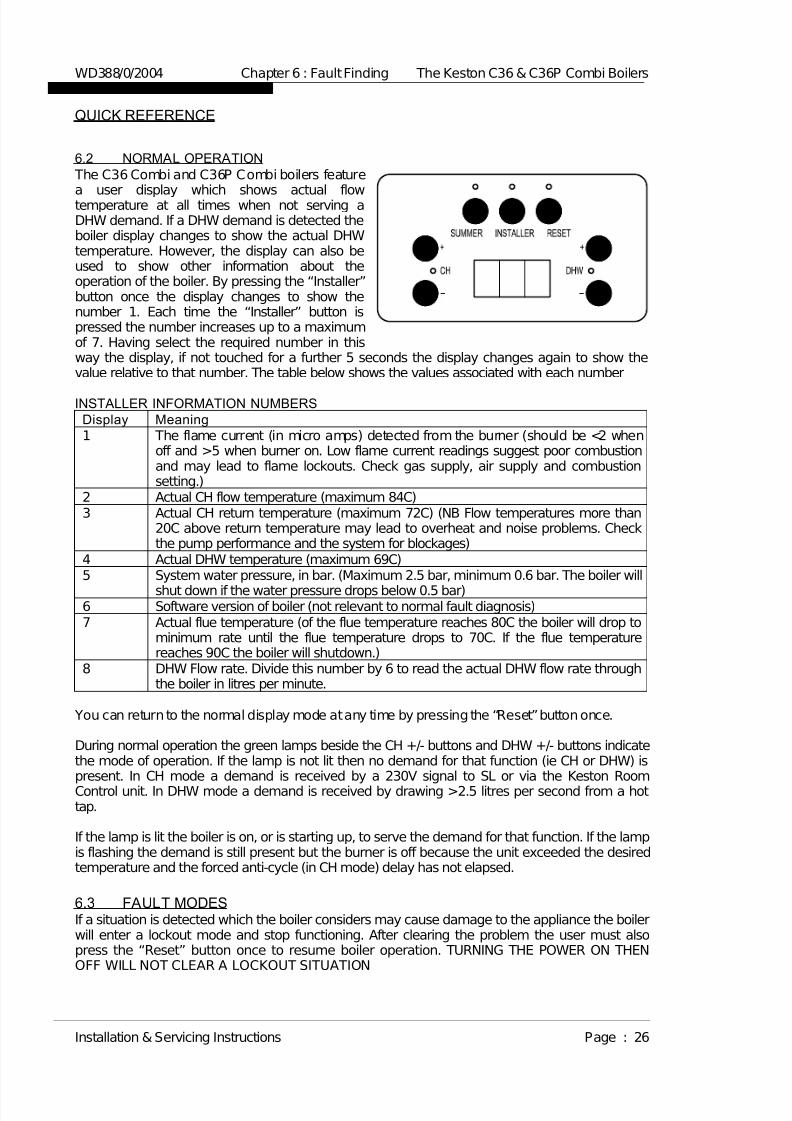
7/28/2019 C36 Combi Full Manual
http://slidepdf.com/reader/full/c36-combi-full-manual 33/56

7/28/2019 C36 Combi Full Manual
http://slidepdf.com/reader/full/c36-combi-full-manual 34/56
ERROR CODES
As E41E99
Flue sensor open circuit - check connections to flue sensor are in placeE46Flue sensor short circuit - check connections to flue sensorE45Return sensor open circuit - check connections to return sensor are in placeE44Return sensor short circuit - check connections to return sensorE43Communication error between fascia and control box - check cablesE41Water pressure too high - check expansion vessel charge and operationE40Reset key fault - replace fascia PCBE38Water pressure error - check system pressure and pressure sensorE37Mains supply frequency incorrect - Check mains voltage system in dwellingE35Mains supply voltage <180V - Check mains voltage system in dwellingE34DHW sensor open circuit - check connections to DHW sensor are in placeE33DHW sensor short circuit - check connections to DHW sensorE32 Flow sensor open circuit - check connections to flow sensor are in placeE31
Flow sensor short circuit - check connections to flow sensorE30
Flame signal lost 5 times in 4 minutes - The flame is unstable, checkcombustion, gas supply, air supply and flue.
E26Control box errors - possible faulty control box.E25
Water pressure lost 4 times in 24 hours - possible leak, check system andboiler.
E24Water filling error - check water pressure sensor.E23Control box errors - possible faulty control box.E12 to E22
The automatic test for calibration of flow and return sensors has failed. Checkboth flow and return sensors are located on the correct pipes and are producingthe correct readings.
E11Control box errors - possible faulty control box.E10
Valve drive error - possible gas valve or control box fault.E09Flame circuit error - possible control box fault..E08
Flue overheat - check combustion and flue temperature vs. return temperature(Installer numbers 7 and 3 above). The flue temperature should be no morethan 10C above return temperature. Possible heat exchanger fault
E07
Fan failure - boiler cannot detect fan rotation. Check fan operation and BOTHconnectors onto fan.
E05
Boiler overheat - check system for blockage, by-pass provision and pumpoperation
E03
False flame - the unit is detecting a flame BEFORE ignition. Check gas valveclosure, power supply polarity and voltage and earth connection.
E02
Ignition failure - the boiler has attempted to light five times and not succeeded -check gas supply, air supply, flue, ignitor condition and spark gap.E01
Descript ion of faultDisplay
WD388/0/2004 Chapter 6 : Fault Finding The Keston C36 & C36P Combi Boilers
Installation & Servicing Instructions Page : 27

7/28/2019 C36 Combi Full Manual
http://slidepdf.com/reader/full/c36-combi-full-manual 35/56
6.4 FUNCTIONAL FLOW WIRING DIAGRAM
WD388/0/2004 Chapter 6 : Fault Finding The Keston C36 & C36P Combi Boilers
Installation & Servicing Instructions Page : 28

7/28/2019 C36 Combi Full Manual
http://slidepdf.com/reader/full/c36-combi-full-manual 36/56
6.5 ELECTRICAL WIRING DIAGRAM
WD388/0/2004 Chapter 6 : Fault Finding The Keston C36 & C36P Combi Boilers
Installation & Servicing Instructions Page : 29
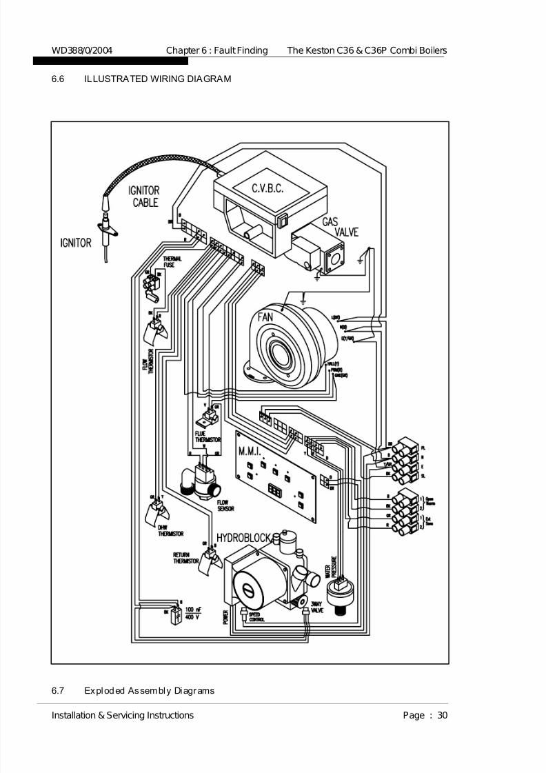
7/28/2019 C36 Combi Full Manual
http://slidepdf.com/reader/full/c36-combi-full-manual 37/56
6.6 ILLUSTRATED WIRING DIAGRAM
6.7 Exploded Assembly Diagrams
WD388/0/2004 Chapter 6 : Fault Finding The Keston C36 & C36P Combi Boilers
Installation & Servicing Instructions Page : 30

7/28/2019 C36 Combi Full Manual
http://slidepdf.com/reader/full/c36-combi-full-manual 38/56
6.7.1 Boiler Controls Assembly
WD388/0/2004 Chapter 6 : Fault Finding The Keston C36 & C36P Combi Boilers
Installation & Servicing Instructions Page : 31

7/28/2019 C36 Combi Full Manual
http://slidepdf.com/reader/full/c36-combi-full-manual 39/56
6.7.2 Waterway, Condensate & Flue Assembly
WD388/0/2004 Chapter 6 : Fault Finding The Keston C36 & C36P Combi Boilers
Installation & Servicing Instructions Page : 32
58
39
56
57-1
57-2
56
57-3
58
5757-4

7/28/2019 C36 Combi Full Manual
http://slidepdf.com/reader/full/c36-combi-full-manual 40/56
WD388/0/2004 Chapter 6 : Fault Finding The Keston C36 & C36P Combi Boilers
Installation & Servicing Instructions Page : 33
57-2
56
56
39
56
57-4
57-3
56
57-1
39

7/28/2019 C36 Combi Full Manual
http://slidepdf.com/reader/full/c36-combi-full-manual 41/56
6.7.3 Air - Gas Assembly
WD388/0/2004 Chapter 6 : Fault Finding The Keston C36 & C36P Combi Boilers
Installation & Servicing Instructions Page : 34

7/28/2019 C36 Combi Full Manual
http://slidepdf.com/reader/full/c36-combi-full-manual 42/56
6.7.4 Casing Assembly
WD388/0/2004 Chapter 6 : Fault Finding The Keston C36 & C36P Combi Boilers
Installation & Servicing Instructions Page : 35

7/28/2019 C36 Combi Full Manual
http://slidepdf.com/reader/full/c36-combi-full-manual 43/56

7/28/2019 C36 Combi Full Manual
http://slidepdf.com/reader/full/c36-combi-full-manual 44/56
7. ROUTINE (ANNUAL) SERVICING
To ensure the continued safe and efficient operation of the boiler it is necessary to carry outroutine servicing at regular intervals. Servicing must be carried out at least once per year. Thefrequency of the servicing will depend upon the particular operating conditions.
It is the law that any service work must be carried out by competent qualified persons.
NB: When servicing ensure that the gas and electrical supplies to the boiler are isolatedbefore any work starts.
Hazardous materials are not used in the construction of the C36 and C36P Combi. However, duecare should be taken when handling boiler components.All joints should be checked for soundness after servicing and before firing the appliance.
After servicing complete the Gas Boiler Commissioning Checklist - Service Interval Record(Chapter 10). These forms (Chapter 10) should be kept in a safe place for the life of the
boiler.
7.1 Pre-Service Checks
It is recommended that an inspection should be carried out prior to shutting down the unitfor servicing. Remove the front cover by removing the screws retaining the top andbottom. The following items should be observed:
a. Smooth starting and running of the blower.b. Smooth lighting of the burner.c. Check for leakage of gas, gas/air or combustion products.d. Check for condensate leaks.e. Check for water soundness.
f. Inspect the flue vent and air intake pipework. Joints must be sound and allpipework well bracketed.g. Check that there is a steady fall back to the boiler from the flue pipe to allow
condensate to run back into the boiler.h. With the boiler operating at a low return temperature (i.e. less than 50oC) check
that the condensate flows freely from the condensate line.
7.2 Recommended Rout ine Service
a. Remove the outer case by first removing the securing screws at the top andbottom of the appliance.
b. Remove the burner head (Section 8.6) and inspect the burner appearance. Blackmarkings or other discoloration's on the gauze indicate too much gas or a lack of
air possibly due to a blocked air inlet. Any breakage's or damage to the burnermesh indicate the burner must be replaced.c. If necessary clean the burner with a mild household detergent and rinse under a
hot running tap.d. If necessary, from visual inspection, clean the heat exchanger using a suitable
stiff plastic bristle brush, vacuum out any large particles and flush the heatexchanger with fresh water until the water flowing from the condensate drain isclear.
e. Remove the condensate trap (Section 8.8) and clean by flushing through withclean running water.
f. Check the electrode assembly mounted on the heat exchanger. If the point isdamaged or burnt replace it.Check that the spark gap measures 4 mm.
g. Replace the burner head, renewing the gasket, and reconnect the gas/air supply.Ensure the flanged gas/air supply joint is air tight.
WD388/0/2004 Chapter 7 : Servicing The Keston C36 Combi & C36P Combi Boilers
Installation & Servicing Instructions Page : 37
7/28/2019 C36 Combi Full Manual
http://slidepdf.com/reader/full/c36-combi-full-manual 45/56
h. Turn on the electrical supply to the boiler and allow the boiler to reach operatingtemperature levels.
i. Remove the combustion test point plug from the flue pipe. This is situated on theflue spigot out of the cabinet.
j. Using an approved combustion tester sample the flue products via the
combustion test point. CO2 levels of between 9.1% and 9.3%, for natural gas andbetween 10.2% and 10.4% for LP gas, should be observed. If such levels are notobserved tune the combustion as described in Chapter 5 - Commissioning. Alsocheck the gas flow as detailed in Sections 5.8 and 5.9
k. Replace the combustion test point plug.l. Recheck the burner pressure by following the procedure detailed in Section 4.7.
m. Check all joints for soundness up to the gas burner.
n. Complete the Gas Boiler Commission ing Checklist - Service Interval Record
(Chapter 10).
WD388/0/2004 Chapter 7 : Servicing The Keston C36 Combi & C36P Combi Boilers
Installation & Servicing Instructions Page : 38
7/28/2019 C36 Combi Full Manual
http://slidepdf.com/reader/full/c36-combi-full-manual 46/56
8. REPLACEMENT OF PARTS
CONTENTS
8.0 GENERAL
8.1 PRECAUTIONS8.2 ACCESS8.3 REPLACEMENT PROCEDURE8.4 ELECTRICAL COMPONENTS
8.4.1 CONTROL PANEL8.4.2 BOILER FLOW & RETURN THERMISTORS8.4.3 CABINET TEMPERATURE SENSOR8.4.4 FLUE THERMISTOR8.4.5 PRESSURE SENSOR8.4.6 MAIN CONTROL BOX8.4.7 COMBUSTION BLOWER8.4.8 GAS CONTROL VALVE8.4.9 GAS INJ ECTOR
8.4.10 DHW THERMISTOR8.4.11 FLOW SENSOR
8.5 SPARK IGNITION/FLAME DETECTION ELECTRODE8.6 BURNER8.7 HEAT EXCHANGER8.8 CONDENSATE TRAP8.9 HYDROBLOCK 8.10 DHW HEAT EXCHANGER8.11 EXPANSION VESSEL
8.0 GENERAL The following must always be carried out by a competent/qualified person.
8.1 PRECAUTIONSi) Always switch off the mains electricity supply and disconnect the plug at the isolating
switch and socket. (If a switch only is used then remove the fuse.)ii) Gain access to the appliance (Section 8.2) and turn off the gas supply at the
appliance service cock.WARNING : Parts of the boiler internal wiring will remain live even after setting the
User Controls to Standby. Shut off the power supply at the isolatingswitch before working on the appliance.
8.2 ACCESSi) Remove the cabinet by removing the screws to the top and bottom of the cabinet.
8.3 REPLACEMENT PROCEDURE
i) Always replace in the reverse order unless otherwise stated.ii) Electrical connections must be remade in accordance with the Electrical Wiring
Diagram (Section 6.5).iii) Test the soundness of any gas carrying or water carrying joint broken during the
service procedures.
8.4 ELECTRICAL COMPONENTS8.4.1 Contro l Panel (Fig. 6.7.1 item 138)
i) Isolate the appliance (Section 8.1)ii) Gain access (Section 8.2)iii) Remove the user control cover by removing the four retaining screws (Fig
6.7.1, item 99 and item 145).iv) Disconnect the Control Panel by unplugging the cable connectors.v) Reassemble (Section 8.3)vi) Check for correct operation of the Control Panel.
WD388/0/2004 Chapter 8 : Replacement Of Parts The Keston C36 Combi & C36P Combi
Installation & Servicing Instructions Page : 39

7/28/2019 C36 Combi Full Manual
http://slidepdf.com/reader/full/c36-combi-full-manual 47/56
8.4.2 Boiler Flow and Return Thermistors (Fig. 6.7.2 - 2/3 item 67)i) Isolate the appliance (Section 8.1)ii) Gain access (Section 8.2)iii) Remove the push on connectors from the thermistor taking note of the
correct positions.
iv) Unclip the thermistor from the pipe.v) Reassemble (Section 8.3)
NB: When fitting the new thermistor it is an advantage to smear a thin filmof heat sink compound between the thermistor and pipe. This,combined with fitting the new thermistor tightly to the pipe, ensures agood contact.
8.4.3 Cabinet Temperature Sensor (Fig 6.7.1 item 153)i) Isolate the appliance (Section 8.1)ii) Gain access (Section 8.2)iii) Remove the cabinet temperature sensor from the connector block by
slackening the retaining screws.iv) Reassemble (Section 8.3)
8.4.4 Flue Thermistor (Fig. 6.7.2 - 1/3 item 68)
i) Isolate the appliance (Section 8.1)ii) Gain access (Section 8.2)iii) Remove the push on connectors from the thermistor taking note of the
correct positions.iv) Unscrew the retaining nut, and remove the thermistor.v) Reassemble (Section 8.3)
NB: When fitting the new thermistor it is an advantage to smear a thin filmof heat sink compound between the thermistor and plate. This,combined with fitting the new thermistor tightly to the plate, ensures a
good contact.
8.4.5 Pressure Sensor (Fig. 6.7.2 - 2/3 item 112)i) Isolate the appliance (Section 8.1)ii) Shut off the water supply to the appliance.iii) Gain access (Section 8.2)iv) Drain the system to below the level of the appliance using the drain off tap
(fig. 6.7.4 - 2/2 item 180) at the base of the return pipe from the heatexchanger.
v) Remove the push on connectors from the pressure sensor taking note of thecorrect positions.
vi) Unscrew the pressure sensor.vii) Reassemble (Section 8.3).
NB: Use a little jointing compound or PTFE tape on the thread.viii) Refill the system (See Section 5 - Commissioning).
8.4.6 Main Contro l Box (Fig. 6.7.1 item 135)i) Isolate the appliance (Section 8.1)
ii) Gain access (Section 8.2)iii) Pull off the multi-pin connectors and HT lead away from the board.iv) Remove the retaining screw (fig. 6.7.1 item 152) securing the control block to
the gas valve (fig. 6.7.3 item 126).v) Remove the control box.vi) Reassemble (Section 8.3)
8.4.7 Combustion Blower (Fig. 6.7.3 item 119)i) Isolate the appliance (Section 8.1)ii) Gain access (Section 8.2)iii) Disconnect the two connector blocks from the combustion blower.iv) Unscrew the bolts securing the venturi (fig 6.7.3 item 125) to the inlet port of
the combustion blower.v) Remove the four nuts securing the combustion blower (fig. 6.7.3 item 121)
outlet flange to the burner and remove the combustion blower.vi) Reassemble (Section 8.3)
WD388/0/2004 Chapter 8 : Replacement Of Parts The Keston C36 Combi & C36P Combi
Installation & Servicing Instructions Page : 40

7/28/2019 C36 Combi Full Manual
http://slidepdf.com/reader/full/c36-combi-full-manual 48/56
NB: When reassembling inspect any gaskets for damage and replace if necessary.
8.4.8 Gas Control Valve (Fig. 6.7.3 item 126)i) Isolate the appliance (Section 8.1)ii) Gain access (Section 8.2)
iii) Remove the push on connector block to the gas valve.iv) Undo the union fitting (Fig 6.7.3 item 104) securing the gas inlet pipe to the
gas control valve.v) Undo the three bolts fixing the mixing venturi (fig 6.7.3 item 132) to the gas
valve.vi) Remove the gas valve.vii) Unscrewing the union fitting from the gas valve.viii) Reassemble (Section 8.3)ix) Check the gas rate and combustion(See Section 5 - Commissioning)
8.4.9 Gas Injector - C36P Combi only (Fig. 6.7.3 item 130)i) Isolate the appliance (Section 8.1)ii) Gain access (Section 8.2)iii) Undo the three bolts fixing the mixing venturi (fig 6.7.3 item 132) to the gas
valve.iv) Remove the injector from the outlet port of the gas valve (fig 6.7.3 item 126)v) Insert the new injectorvi) Reassemble (Section 8.3)vii) Check the gas rate and combustion (See Section 5 - Commissioning)
8.4.10 DHW Thermistor (Fig. 6.7.2 - 2/3 item 108)i) Isolate the appliance (Section 8.1)ii) Gain access (Section 8.2)iii) Remove the push on connectors from the thermistor taking note of the
correct positions.iv) Unclip the thermistor from the pipe.v) Reassemble (Section 8.3)
NB: When fitting the new thermistor it is an advantage to smear a thin film
of heat sink compound between the thermistor and pipe. This,combined with fitting the new thermistor tightly to the pipe, ensures agood contact.
8.4.11 Flow Sensor (Fig. 6.7.2 - 3/3 item 94)i) Isolate the appliance (Section 8.1)ii) Gain access (Section 8.2)iii) Shut off the water supply (CWS) to the DHW heat exchanger (Fig. 6.7.2 -
1/3 item 57).iv) Remove the push on connector from the sensor taking note of the correct
position.v) Disconnect the union nuts (Fig. 6.7.2 - 3/3 item 100 and Fig. 6.7.4 - 2/2 item
177) and the fixing nut (Fig. 6.7.2 - 3/3 item 203) from the sensor.vi) Reassemble (Section 8.3)
NB: When reassembling inspect the gaskets for damage and replaceif necessary.
8.5 SPARK IGNITION/FLAME DETECTION ELECTRODE (Fig. 6.7.2 - 1/3 item 48)i) Isolate the appliance (Section 8.1)ii) Gain access (Section 8.2)iii) Remove the pull off HT lead to the spark ignition electrode.iv) Undo the screws to the spark ignition electrode flange located on the heat
exchanger top panel and withdraw the spark ignition electrode.v) Reassemble (Section 8.3)
NB: When reassembling inspect the gasket for damage and replace if necessary.
With the new spark ignition electrode in place it is essential to ensure the gapbetween the tip of the electrode and the burner surface is 4 mm. Distances
WD388/0/2004 Chapter 8 : Replacement Of Parts The Keston C36 Combi & C36P Combi
Installation & Servicing Instructions Page : 41

7/28/2019 C36 Combi Full Manual
http://slidepdf.com/reader/full/c36-combi-full-manual 49/56
above or below 4 mm will affect ignition performance. If necessary gently
bend the electrode taking care not to damage the ceramic insulator. 8.6 BURNER (Fig. 6.7.2 - 1/3 items 46)
i) Isolate the appliance (Section 8.1)ii) Gain access (Section 8.2)iii) Remove the combustion blower (Section 8.4.7)iv) Remove the 4 nuts fixing the burner to the top of the heat exchanger.v) Withdraw the burner from the top of the heat exchanger.vi) Reassemble (Section 8.3)
NB: When reassembling inspect any gaskets for damage and replace if necessary.
8.7 HEAT EXCHANGER (Fig. 6.7.2 - 1/3 item 39)i) Isolate the appliance (Section 8.1)ii) Gain access (Section 8.2)iii) Shut off the water supply to the appliance.iv) Remove the burner (Section 8.6)v) Drain the system to below the level of the appliance using the drain off tap (Fig.
6.7.4 - 2/2 item 180) at the base of the boiler return pipe.vi) Remove the flue thermistor (Section 8.4.4)vii) Remove the spark ignition/flame detection electrode (Section 8.5)viii) Remove the flue connection by slackening the retaining strap and pulling the flue off
the heat exchanger spigot.ix) Remove the condensate trap hose (Fig 6.7.2 - 1/3 item 54) by releasing the retaining
clamp and pulling the hose away from the spigot at the base of the heat exchanger.x) Disconnect the flow and return pipe union nuts (Fig 6.7.2 - 2/3 & Fig. 6.7.2 - 3/3 item
60) from the heat exchanger.xi) Remove the two screws (Fig. 6.7.2 - 1/3 item 41) fixing the heat exchanger to the top
and the screw (Fig. 6.7.2 - 1/3 item 42) fixing the heat exchanger to the bottom.xii) Remove the heat exchanger
xiii) Reassemble (Section 8.3)xiv) Recommission (Section 5 - Commissioning)
8.8 CONDENSATE TRAP (Fig. 6.7.2 - 1/3 item 51)i) Isolate the appliance (Section 8.1)ii) Gain access (Section 8.2)iii) Disconnect the condensate line from the base of the heat exchanger.iv) Disconnect the condense line from the projection of the condensate trap from the
base of the cabinet.v) Withdraw the condensate trap.vi) Mop up any spilled condensate.vii) Reassemble (Section 8.3)
NB: When re-fitting the condensate trap pour water onto the condensate hose
from the base of the heat exchanger until nearly full. Then reconnect thecondensate hose to the base of the heat exchanger.
8.9 HYDROBLOCK PUMP (Fig. 6.7.2 - 1/3 item 56)i) Isolate the appliance (Section 8.1)ii) Gain Access (section 8.2)iii) Isolate the waterways to the boiler using the system isolation valves.iv) Drain the system to below the level of the appliance using the drain off tap (Fig.
6.7.4 - 2/2 item 180) at the base of the boiler return pipe.v) Undo the screw (Fig. 6.7.1 item 145) to the panel support (Fig. 6.7.4 - 1/2 item 35)
and rotate it on the right.vi) Disconnect the pump electrical cable from the connections box of the pump head
taking note of the correct position.vii) Remove the four allen bolts securing the pump head to the hydroblock back body.viii) Remove the pump head.
WD388/0/2004 Chapter 8 : Replacement Of Parts The Keston C36 Combi & C36P Combi
Installation & Servicing Instructions Page : 42
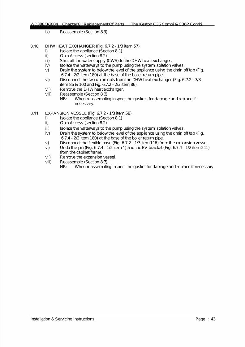
7/28/2019 C36 Combi Full Manual
http://slidepdf.com/reader/full/c36-combi-full-manual 50/56
ix) Reassemble (Section 8.3)
8.10 DHW HEAT EXCHANGER (Fig. 6.7.2 - 1/3 item 57)i) Isolate the appliance (Section 8.1)ii) Gain Access (section 8.2)
iii) Shut off the water supply (CWS) to the DHW heat exchanger.iv) Isolate the waterways to the pump using the system isolation valves.v) Drain the system to below the level of the appliance using the drain off tap (Fig.
6.7.4 - 2/2 item 180) at the base of the boiler return pipe.vi) Disconnect the two union nuts from the DHW heat exchanger (Fig. 6.7.2 - 3/3
item 86 & 100 and Fig. 6.7.2 - 2/3 item 86).vii) Remove the DHW heat exchanger.viii) Reassemble (Section 8.3)
NB: When reassembling inspect the gaskets for damage and replace if necessary.
8.11 EXPANSION VESSEL (Fig. 6.7.2 - 1/3 item 58)i) Isolate the appliance (Section 8.1)
ii) Gain Access (section 8.2)iii) Isolate the waterways to the pump using the system isolation valves.iv) Drain the system to below the level of the appliance using the drain off tap (Fig.
6.7.4 - 2/2 item 180) at the base of the boiler return pipe.v) Disconnect the flexible hose (Fig. 6.7.2 - 1/3 item 116) from the expansion vessel.vi) Undo the pin (Fig. 6.7.4 - 1/2 item 4) and the EV bracket (Fig. 6.7.4 - 1/2 item 211)
from the cabinet frame.vii) Remove the expansion vessel.viii) Reassemble (Section 8.3)
NB: When reassembling inspect the gasket for damage and replace if necessary.
WD388/0/2004 Chapter 8 : Replacement Of Parts The Keston C36 Combi & C36P Combi
Installation & Servicing Instructions Page : 43
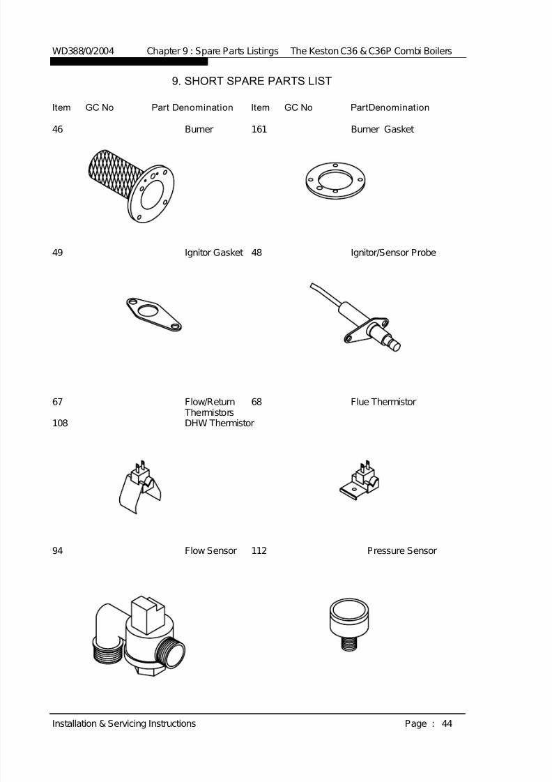
7/28/2019 C36 Combi Full Manual
http://slidepdf.com/reader/full/c36-combi-full-manual 51/56
9. SHORT SPARE PARTS LIST
Item GC No Part Denomination Item GC No PartDenomination
46 Burner 161 Burner Gasket
49 Ignitor Gasket 48 Ignitor/Sensor Probe
67 Flow/Return 68 Flue Thermistor
Thermistors108 DHW Thermistor
94 Flow Sensor 112 Pressure Sensor
WD388/0/2004 Chapter 9 : Spare Parts Listings The Keston C36 & C36P Combi Boilers
Installation & Servicing Instructions Page : 44

7/28/2019 C36 Combi Full Manual
http://slidepdf.com/reader/full/c36-combi-full-manual 52/56
126 Gas Valve 119 Fan
124 Air-Gas Mixer 138 Fascia Panel
135 Control Box 57 DHW HeatExchanger
56 Pump block 58 Expansion Vessel
WD388/0/2004 Chapter 9 : Spare Parts Listings The Keston C36 & C36P Combi Boilers
Installation & Servicing Instructions Page : 45

7/28/2019 C36 Combi Full Manual
http://slidepdf.com/reader/full/c36-combi-full-manual 53/56
SHORT SPARE PARTS LIST FOR THE KESTON
CONDENSING BOILER RANGE
Item GC No Part Denomination
46 Burner161 Burner Gasket48 Ignitor49 Ignitor Gasket108 DHW Thermistor67 Flow/Return Thermistor68 Flue Thermistor94 Flow Sensor112 Pressure Sensor
119 Fan126 Gas Valve124 Air-Gas Mixer138 Control Panel135 Control Block57 DHW Heat Exchanger56 Hydroblock58 Expansion Vessel
WD388/0/2004 Chapter 9 : Spare Parts Listings The Keston C36 & C36P Combi Boilers
Installation & Servicing Instructions Page : 46
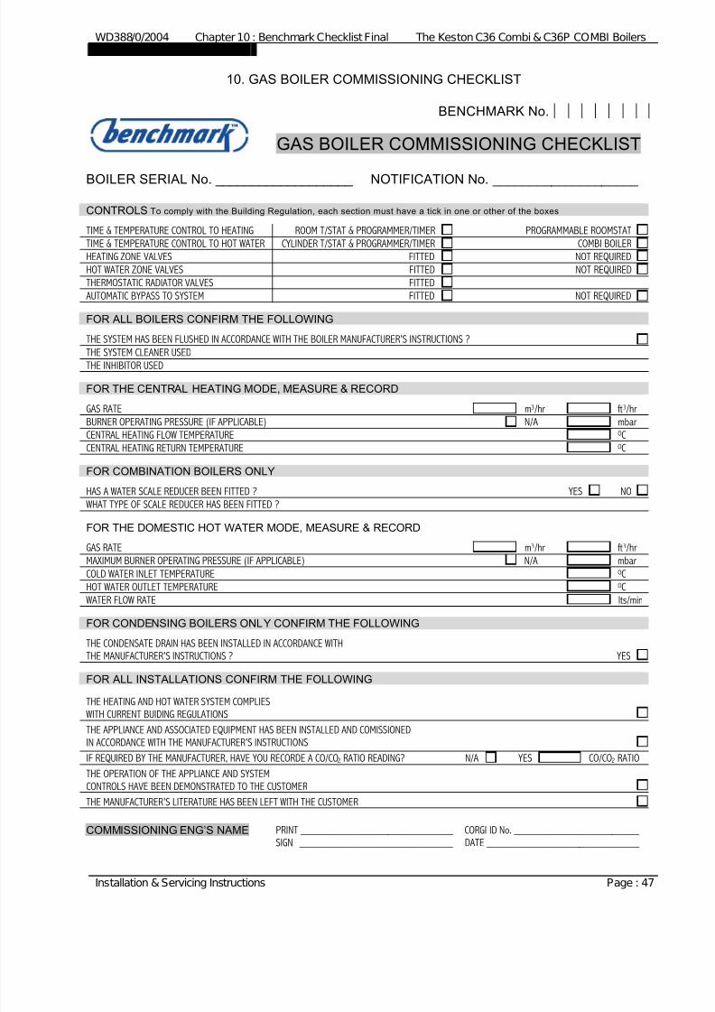
7/28/2019 C36 Combi Full Manual
http://slidepdf.com/reader/full/c36-combi-full-manual 54/56
WD388/0/2004 Chapter 10 : Benchmark Checklist Final The Keston C36 Combi & C36P COMBI Boilers
Installation & Servicing Instructions Page : 47
10. GAS BOILER COMMISSIONING CHECKLIST
BENCHMARK No.
GAS BOILER COMMISSIONING CHECKLIST
BOILER SERIAL No. ___________________ NOTIFICATION No. ____________________
CONTROLS To comply with the Building Regulation, each section must have a tick in one or other of the boxes
TIME & TEMPERATURE CONTROL TO HEATING ROOM T/STAT & PROGRAMMER/TIMER PROGRAMMABLE ROOMSTAT
TIME & TEMPERATURE CONTROL TO HOT WATER CYLINDER T/STAT & PROGRAMMER/TIMER COMBI BOILER
HEATING ZONE VALVES FITTED NOT REQUIRED
HOT WATER ZONE VALVES FITTED NOT REQUIRED
THERMOSTATIC RADIATOR VALVES FITTED
AUTOMATIC BYPASS TO SYSTEM FITTED NOT REQUIRED
FOR ALL BOILERS CONFIRM THE FOLLOWING
THE SYSTEM HAS BEEN FLUSHED IN ACCORDANCE WITH THE BOILER MANUFACTURER’S INSTRUCTIONS ?
THE SYSTEM CLEANER USEDTHE INHIBITOR USED
FOR THE CENTRAL HEATING MODE, MEASURE & RECORD
GAS RATE m3/hr ft3/hr
BURNER OPERATING PRESSURE (IF APPLICABLE) N/A mbar
CENTRAL HEATING FLOW TEMPERATURE OC
CENTRAL HEATING RETURN TEMPERATURE OC
FOR COMBINATION BOILERS ONLY
HAS A WATER SCALE REDUCER BEEN FITTED ? YES NO
WHAT TYPE OF SCALE REDUCER HAS BEEN FITTED ?
FOR THE DOMESTIC HOT WATER MODE, MEASURE & RECORDGAS RATE m3/hr ft3/hr
MAXIMUM BURNER OPERATING PRESSURE (IF APPLICABLE) N/A mbar
COLD WATER INLET TEMPERATURE OC
HOT WATER OUTLET TEMPERATURE OC
WATER FLOW RATE lts/min
FOR CONDENSING BOILERS ONLY CONFIRM THE FOLLOWING
THE CONDENSATE DRAIN HAS BEEN INSTALLED IN ACCORDANCE WITH
THE MANUFACTURER’S INSTRUCTIONS ? YES
FOR ALL INSTALLATIONS CONFIRM THE FOLLOWING
THE HEATING AND HOT WATER SYSTEM COMPLIES
WITH CURRENT BUIDING REGULATIONS
THE APPLIANCE AND ASSOCIATED EQUIPMENT HAS BEEN INSTALLED AND COMISSIONED
IN ACCORDANCE WITH THE MANUFACTURER’S INSTRUCTIONS
IF REQUIRED BY THE MANUFACTURER, HAVE YOU RECORDE A CO/CO2 RATIO READING? N/A YES CO/CO2 RATIO
THE OPERATION OF THE APPLIANCE AND SYSTEM
CONTROLS HAVE BEEN DEMONSTRATED TO THE CUSTOMER
THE MANUFACTURER’S LITERATURE HAS BEEN LEFT WITH THE CUSTOMER
COMMISSIONING ENG’S NAME PRINT ____________________________ CORGI ID No. _______________________
SIGN ____________________________ DATE ____________________________

7/28/2019 C36 Combi Full Manual
http://slidepdf.com/reader/full/c36-combi-full-manual 55/56
WD388/0/2004 Chapter 10 : Benchmark Checklist Final The Keston C36 Combi & C36P COMBI Boilers
Installation & Servicing Instructions Page : 48
SERVICE INTERVAL RECORD
It is recommended that your heating system is serviced regularly
and that you complete the appropriate Service Interval Record Below
Service Provider . Before completing the appropriate Service Interval Record below, please ensure you have carried out the service
as described in the boiler manufacturer’s instructions. Always use the manufacturer’s specified spare part when replacing all controls SERVICE 2 DATE
ENGINEER NAME
COMPANY NAME
TEL No.
CORGI ID CARD SERIAL No.
COMMENTS
SIGNATURE
SERVICE 1 DATE
ENGINEER NAME
COMPANY NAME
TEL No.
CORGI ID CARD SERIAL No.
COMMENTS
SIGNATURE
SERVICE 3 DATE
ENGINEER NAME
COMPANY NAME TEL No.
CORGI ID CARD SERIAL No.
COMMENTS
SIGNATURE
SERVICE 4 DATE
ENGINEER NAME
COMPANY NAME TEL No.
CORGI ID CARD SERIAL No.
COMMENTS
SIGNATURE
SERVICE 6 DATE
ENGINEER NAME
COMPANY NAME
TEL No.
CORGI ID CARD SERIAL No.
COMMENTS
SIGNATURE
SERVICE 5 DATE
ENGINEER NAME
COMPANY NAME
TEL No.
CORGI ID CARD SERIAL No.
COMMENTS
SIGNATURE
SERVICE 7 DATE
ENGINEER NAME
COMPANY NAME
TEL No.
CORGI ID CARD SERIAL No.
COMMENTS
SIGNATURE
SERVICE 8 DATE
ENGINEER NAME
COMPANY NAME
TEL No.
CORGI ID CARD SERIAL No.
COMMENTS
SIGNATURE
SERVICE 9 DATE
ENGINEER NAME
COMPANY NAME
TEL No.
CORGI ID CARD SERIAL No.
COMMENTS
SIGNATURE
SERVICE 10 DATE
ENGINEER NAME
COMPANY NAME
TEL No.
CORGI ID CARD SERIAL No.
COMMENTS
SIGNATURE
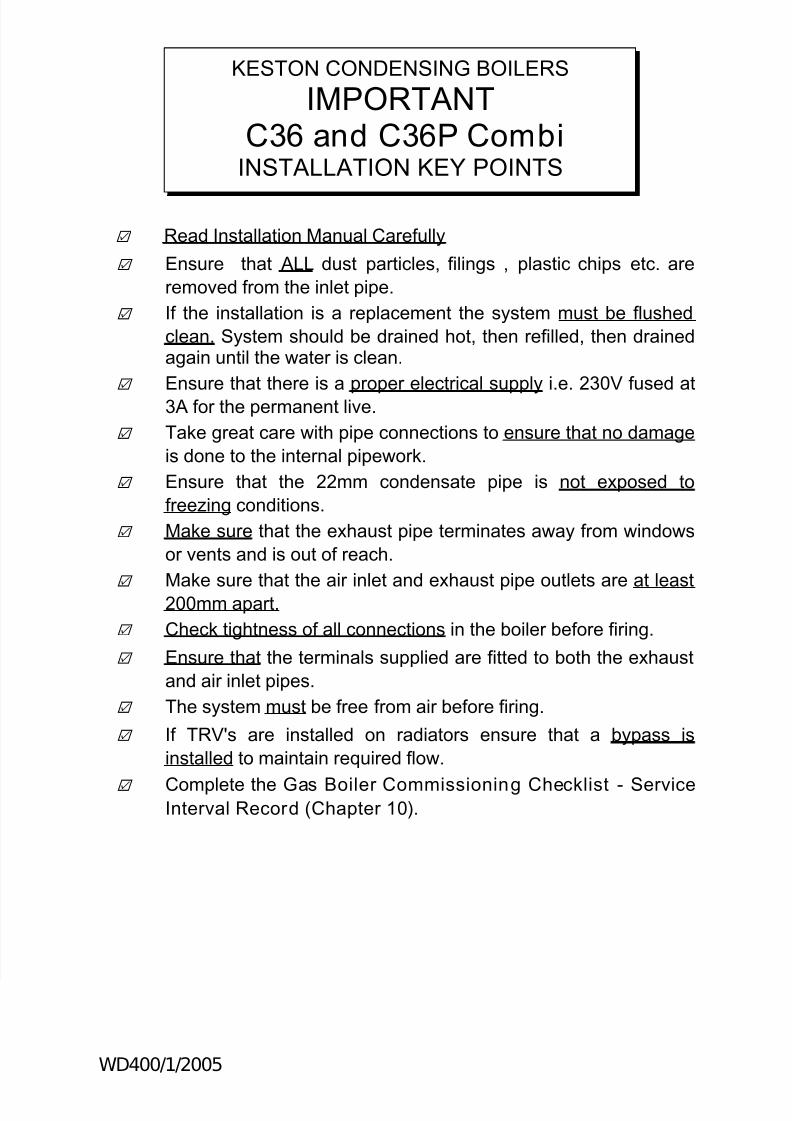
7/28/2019 C36 Combi Full Manual
http://slidepdf.com/reader/full/c36-combi-full-manual 56/56
† Read Installation Manual Carefully
† Ensure that ALL dust particles, filings , plastic chips etc. are
removed from the inlet pipe.
† If the installation is a replacement the system must be flushed
clean. System should be drained hot, then refilled, then drainedagain until the water is clean.
†
Ensure that there is a proper electrical supply i.e. 230V fused at3A for the permanent live.
† Take great care with pipe connections to ensure that no damage
is done to the internal pipework.
† Ensure that the 22mm condensate pipe is not exposed to
freezing conditions.
† Make sure that the exhaust pipe terminates away from windows
or vents and is out of reach.
†
Make sure that the air inlet and exhaust pipe outlets are at least200mm apart.
† Check tightness of all connections in the boiler before firing.
† Ensure that the terminals supplied are fitted to both the exhaust
and air inlet pipes.
† The system must be free from air before firing.
† If TRV's are installed on radiators ensure that a bypass is
installed to maintain required flow.
† Complete the Gas Boiler Commissioning Checklist - ServiceInterval Record (Chapter 10).
KESTON CONDENSING BOILERS
IMPORTANT
C36 and C36P CombiINSTALLATION KEY POINTS