c6e'94/oc2e lj‘6 - defense technical information center no. no. no. no. 11. title (include...
TRANSCRIPT

AFWAL-TR-85-4139
AD4 j49-73;
GUINIER-LENNE HIGH TEMPERATURE X-RAY CAMERA:
INSTRUCTIONS FOR USE
David P. Anderson
Universal Energy Systems4401 Dayton-Xenia RdDayton, Ohio 45432
February 1986
INTERIM REPORT COVERING MAY 83 - SEPTEMBER 83
Approved for Public Release - Distribution is Unlimited
MATERIALS LABORATORYAIR FORCE WRIGHT AERONAUTICAL LABORATORIESAIR FORCE SYSTEMS COMMANDWRIGHT-PATTERSON AIR FORCE BASE, OHIO 45433
c6e'94/Oc2e Lj•6

NOTICE
When Government drawings, specifications, or other data are used forany purpose other than in connection with a definely related Governmentprocurement operation, the United States Government therby incurs noresponsibility nor any obligation whatsoever; and the fact that thegovernment may have formulated, furnished, or in any way supplied the saiddrawings, specifications, or other data, is not to be regarded byimplication or otherwise as in any manner licensing the holder or any otherperson or corporation, or conveying any rights or permission to manufactureuse or sell any patented invention that may in any way be related thereto.
This report has been reviewed by the Office of Public Affairs (ASD/PA)and is released to the National Inforbiation Service (NTIS). At NTIS, itwill be available to the general public, including foreign nations.
This technical report has been reviewed and is approved forpublication.
WALTER W. ADAMS, Project Scientist H.L. VAN DEUSEN, ChiefPolymer Branch Polymer BranchNonmetallic Materials Division Nonmetallic Materials Division
FOR THE COMMANDER
•RRILL. M]INIS/ SESK Director
Nonmetallic Mate ials Division
"If your address has changed, if you wish to be removed from our mailinglist, or if the addressee is no longer employed by your organization pleasenotify AFWAL/MLBP, WPAFB, OH 45433 to help us maintain a current mailinglist".
Copies of this report should not be returned unless return is required bysecurity considerations, contractual obligations, or notice on a specificdocument.
Unclassified
SECURITY CLASSIFICATION OF THIS PAGE
REPORT DOCUMENTATION PAGE
la. REPORT SECURITY CLASSIFICATION lb. RESTRICTIVE MARKINGS
Unclassified2s, SECURITY CLASSIFICATION AUTHORITY 3. DISTRIBUTION/AVAILABILITY OF REPORT
Approved for public release; distribution2b. OECLASSIFICATION/DOWNGRADING SCHEDULE unlimited
4. PERFORMING ORGANIZATION REPORT NUMBER(S) 5. MONITORING ORGANIZATION REPORT NUMBER(S)
AFWAL-TR-85-4139
6a. NAME OF PERFORMING ORGANIZATION 6b. OFFICE SYMBOL 7a. NAME OF MONITQRING ORGANIZATION(Ifapplicable) Air Force Wright Aeronautical Labs
Universal Energy Systems Materials Laboratory (AFWAL/MLBP)
6c. ADDRESS (City, State and ZIP Code) 7b. ADDRESS (City, State and ZIP Code)
4401 Dayton-Xenia Road Wright-Patterson AFBDayton, OH 45432 OH 45433-6533
Sm. NAME OF FUNDING/SPONSORING 8~b. OFFICE SYMBOL 9. PROCUREMENT INSTRUMENT IDENTIFICATION NUMBERNll (TIpiabe
A• 'h'1 ronautical Labs (,f appicable)
Materials Laboratory jAFWAL/MLBP F33615-82-C-5001 and SB5448-82-C-00768c. ADDRESS (City. State and ZIP Code) 10. SOURCE OF FUNDING NOS.
PROGRAM PROJECT TASK WORK UNITELEMENT NO. NO. NO. NO.
11. TITLE (Include Security Classification) 61102F 2303 Q3 07Guinier-Lenne High Temperature X-ray Camera:
12. PERSONAL AUTHOR(S)
David P. Anderson13s. TYPE OF REPORT 13b. TIME COVERED 14. DATE OF REPORT (Yr., Mo., Day) 15. PAGE COUNT
terim FROMI TO p February 1986 4216. SUPPLEMENTARY NOTATION
17. COSATI CODES 18. SUBJECT TERMS (Continue on reverse if necessary and identify by block number)
FIELD GROUP SUB. GR. High Temperature Photography Guinier-Lenne X-ray9 2 6 a amer
20 2 2 X-ray Diffraction PBT Poly(p-phenienebenzobisthiazole)19. ABSTRACT (Continue on reverse if necessary and identify by block number)
This manual was written to provide future users of Guinier-Lenne cameras in the Air ForceMaterials Laboratory with a clearly written set of instructions for set-up and operationof these cameras. This manual is intended to supplant the current manual, which is inpoor condition and difficult to read. Borrowing information from the current manual,the Guinier-de Wolff operating instructions, and another manual, this author hasattempted to gather as much relevant information as possible to instruct the readerin the operation of a Guinier-Lenne high temperature X-ray camera.
20. DISTRIBUTION/AVAILABILITY OF ABSTRACT 21. ABSTRACT SECURITY CLASSIFICATION
UNCLASSIFIED/UNLIMITED El SAME AS RPT. R DTIC USERS 0] Unclassified
22a. NAME OF RESPONSIBLE INDIVIDUAL 22b. TELEPHONE NUMBER 22c. OFFICE SYMBOL
W. W. Adams 5 cIl•r -a 1C'jge, AFWAL/MLBPI i I
DD FORM 1473, 83 APR EDITION OF 1 JAN 73 iS OBSOLETE.SECURITY CLASSIFICATION OF THIS PAGE

UnclassifiedSECURITY CLASSIFICATION OF THIS PAGE
11. (continued) Instructions for Use.
UnclassifiedSECURITY CLASSIFICATION OF THIS PAGE

FOREWORD
This Interim Technical Report was prepared by the Universal Energy
Systems, 4401 Dayton-Xenia Road, Dayton, OH 45432 under Air Force Contract
No. F33615-82-C-S0O1/SB 5448-82-C-0076. It was administered under the
direction of the Materials Laboratory, Air Force Wright Aeronautical
Laboratories, Air Force Systems Command, Wright-Patterson Air Force Base, OH
with Dr. W. Wade Adams as the Project Scientist.
iii
TABLE OF CONTENTS
Section Page
1. INTRODUCTION . . . . . . . . . . . . . . . . . . . . . . .
2. CAMERA CONSTRUCTION . . . . . . . . . . . . . . . . . . . . . 2
3. FOCUSSING PRINCIPLE . . . . . . . . . . . . . . . . . . . . . 9
4. SAFETY . . . . *. . . . . . . . . . . . . . . . . . . . . .. . 15
5. ALIGNMENT
5.1 Preliminary Adjustments ................. . 16
5.1.1 Crystal insertion .... .. .. .. .. .. .. 16
5.1.2 Camera position . . ... .. .. .. ..... 16
5.2 Final Adjustments ... . . . . . .. ... . 18
5.2.1 Camera housing adjustments . . . . . 18
5.2.2 Crystal monoohromator adjustments .... .. .. . 19
6. OPERATION . . . . . . . . . . . . . . . . . 23
6.1 Temperature Control ...... . . . . . . . . . .. . 23
6.2 Time and Speed Selection . . .... .. . . . .. . 24
6.3 Sample Preparation .... . . .................... *24
6.4 Recording Film . . . . . . . . . . . . . . 25
REFERNECES ...... . . . . . . . . . . . . . . . . . . . 28
APPENDIX A: Sample Operation Results . . . . . . ... 29
V

List of Figures Page
1. Guinier-Lenne Camera . . . . . . . . . ...... 4
2. Monochromator Housing (Front View) . . . . . . . . . . . . . . 5
3. Monochromator Housing (Back View) ... . . . . . . . . . . 5
4. Sample Holder . .. ................... . 6
5. Scattering Slit Area ...................... 7
6. Scattering Slit Area - diffraction window removed . . . .7
7. Film Cassette . . . . . ................... 8
8. Configuration of Camera .................. 12
9. Monochomator Detail ..................... 13
10. Focussing Principle ................ .. . 14
11. Types of Main Beam Images . . . ............... 21
12. Main Beam Ka Doublet Splitting . . . . . . ... 22
13. Control Box ......................... 26
14. Temperature Control Chart ..... .... ......... 27
Al. Time-Temperature Response of Guinier-Lenne Furnace . . . . . 32
A2. Guinier-Lenne Dynamic Diffraction Negative for PBT . . . . . . 33
A3. Selected Bragg Scans from PBT heating ............ 34
vi

Photograph Reference Numbers
No. Figures
1. Metal bellows (lead covered) . . . . . . . . . . . . . . 1,32. Monochromator housing . . . . . . . . . . . . . . . . . 1,8,103. Slot (Fl) . . . . . . . . . . . . . . . . . . . . . . . 1f293
4. Vacuum port ...................... . . . . I. . 1
5. Sample holder . . . ... . . . . .. . . . . . . 1,4,8,106. Heating chamber . . . . . . . . . . . . . . . . . . . . 1,107. Sample access port. . . . . . . . . . . . . . . . . . . 18. Beam catcher . . . . . . . . . . . . . . . . . . . . . 1,6,109. Film cassette holder . . . . . . . . . . . . .1,1110. " slide .
11. " release handles ............. 112. Cooling water hoses . . . . . . . . . . . . . . . 113. Reflex hand wheel . . . . . . . . . . . . . . ... . 114. Leveling nuts . . . . . . . . . . . . . . . . . . 1
15. Monochromator curvature dial . . . . . .. . . . 2,316. Quartz monochromator crystal . . . . . . . .. . 217. Monochromator adjustment arm lock screw . . . . .... 218. Diaphragm . . . . . . . . . * .. . . . . . 2,1019. Torsion adjustment screw . . . . . . . . . . . . . 220. " hole . . . . . . . . . . . . . 2,321. Monochromator micrometer screw . . . . .. . . . . 2,322. " adjustment arm 223. position scale 324. index . . . . . . . . . . . 325. lockscrew . . . . . . . . 326. Diaphragm handle . . . . . . . . . . . . . . . . .... 327. Logarithmic slide . 6 . . .......... .*. 328. " " and curvature lock screw .*.6.. 329. Crystal radiation type scale . . . . . . ........ 330. " " index.............. . . . 331. Marking diaphragm . . . . . . . . . . . . . . . . 532. Diffraction slit .... .......... . . . ... . . . 533. Film cassette reference scale . . . . . . . . . ... 634. " main beam window . . . . . ........ 735. Beam Catcher Control...... . . . . . . .. . .1336. Low Temp Control Variac .......... . . . . . . 1337. High " ".".1338. Ranger Indicator " 1339. Film Speed Switch . . . . . . . . . . . . . . . . 1340. Time Select ". ............................ . 1341. Temperature Direction Switch . . . . . . ....... 1342. Continuous/Cycle Switch . .......... . . . .. 13
vii
1. INTRODUCTION
The Guinier-Lenne (G-L) camera is designed to photographically
record wide angle x-ray diffraction (WAXD) patterns as a function of
temperature. Structural changes can be followed in this way and
temperatures of those changes determined. The types of processes
typically examined are:
- thermal expansion,
- phase changes,
- chemical transformations, and
- recrystallization of amorphous materials;
but any change in a specimen which is temperature dependent and results
in a change in its WAXD pattern can also be examined with this camera.
The G-L camera is capable of heating a sample from ambient
conditions to 12000 C. The time to reach this or any other final
temperature is fixed at intervals of 3 to 120 hours. The temperature
may be increased or decreased during the experiment with the sample
maintained at the final temperature or allowed to return to ambient at
the end of the run.
The sample chamber may be evacuated or swept with a gas, either
inert or reactive.
The film cassette is capable of recording diffraction angles from 3
to almost 9g0 20, with a minimum Ka and Ka2 dispersion. The position
of the film can be marked at 00 diffraction angle. The film cassette
can be moved vertically by hand for a series of diffraction patterns or
by electric motor for continously changing patterns. The film size is
174 mm by up to 260 mm. Film speeds can be varied discreetly from 0.5
to 20 mm/hr for maximum dynamic exposure times of 500 hours.
1

The width of the diffraction slit can be varied with factory
prepared slits of 1, 3, and 5 mm. The wider a slit the more intensity
reaches the recording film but with a corresponding decrease in time
resolution.
2. CAMERA CONSTRUCTION
This camera, shown in Figure 1, is designed to be mounted
horizontally with the focussing circle parallel to and 300-350 mm above
the table. The support base has three legs, each with leveling nuts
(14) to adjust the height and tilt of the focussing plane. One of the
support legs is situated directly below the monochromator center so that
the camera may be pivoted during the coarse adjustments while
maintaining a constant take-off angle and anode-to-monochromator
distance.
The upper base is attached to the lower base via a pivot controlled
by thereflex wheel (13). Attached to the upper base are the
monochromator housing (2), sample chamber (5) and furnace (6), and the
film cassette holder (9) and slide (10). The electric film cassette
motors to are located within the upper base.
The monochromator housing (2) contains the quartz monochromator
crystal (16) (shown being inserted in Figure 2) and various adjusting
controls (see Figure 3). The x-rays enter the housing through the
attached metal bellows (1) (usually wrapped with lead foil) and exit
into slot F1 (3) after being diffracted by the monochromator crystal.
The sample chamber and furnace are an integral unit through which
the x-rays pass. X-rays enter through a beryllium window at slot F1,
pass through the sample at the center of the furnace, and the main beam
is stopped by the beam catcher (8) while the diffracted beam exits
through another beryllium window and the diffraction slit (32). The
diffracted rays are then recorded on the photographic film in the film
cassette.
2

The heating block consists of a cylindrical metal housing
containing various openings and holding a ceramic mass and outer cooling
coils. The ceramic mass is wound with platinum-rhodium wire and is
connected to the heater control, which electrically heats the ceramic
mass and the sample as well. Cooling water (12) cools the outer surface
of the metal housing preventing the film from getting hot. The vacuum
port (4) can be connected to a vacuum pump or any sweep gas cylinder.
The sample holder (shown in detail in Figure 4) can hold films,
foils, powders (pressed into a platinum screen or other holder, or any
other sample approximately 10 mm x 5 mm. The head of the sample holder
is made of a platinum-iridium alloy and connected to the screw base with
a corundum tube. A platinum-rhodium/platinum thermocouple is imbedded
in this tube. Samples can be loaded by removing the entire holder or
through the side sample access port (7).
The beam catcher (8), located within the furnace assembly can be
moved in and out of position electro-magnetically (35). The main beam
can mark the film position by momentarily moving the beam catcher to the
open position while the marking diaphragm (31) is in place (see Figures
5 and 6). The beam catcher must also be placed in the open position
during certain phases of alignment.
The film cassette holder (Figure 7) is attached to the film
cassette slide such that the recording film is coincident with the
diffraction circle described later. The holder can be moved up or down
by hand by squeezing the release handles (11). The motors, which can be
electronically switched among several speeds, drive a shaft which in
turn drives the slide holding the film cassette. The slide position can
be observed on the film cassette reference scale (33).
3

7A
Fiue1AGiirLnn aea

Figure 2. Monochromator Housing (front view).
71Tl "7
Figure 3. Monochromator Housing (back view).
5
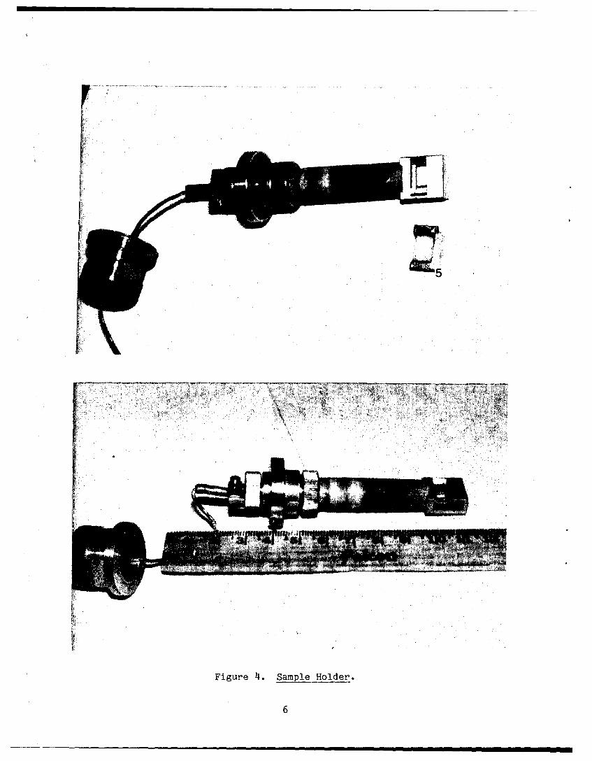
Figure 1*Sample Holder.
6

S~~32 ..
Figure 5. Scattering Slit Area.
Figure 6. Scattering Slit Area - diffraction window removed.

Qi)bo
r04
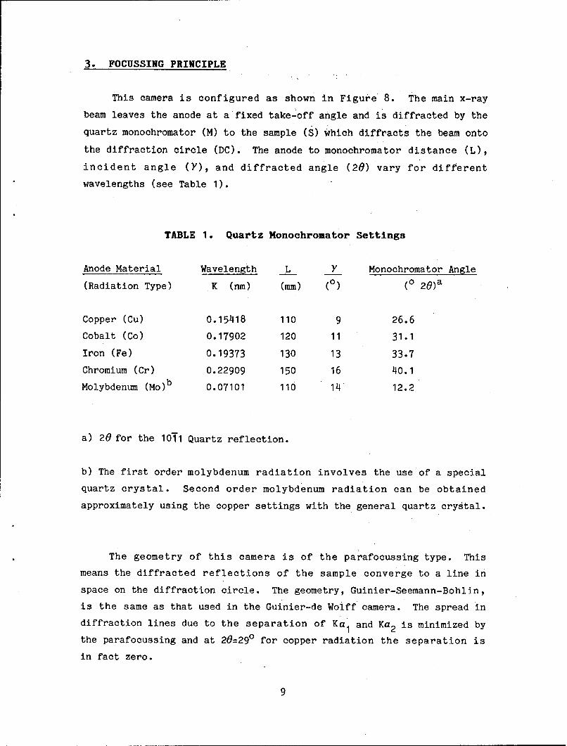
3. FOCUSSING PRINCIPLE
This camera is configured as shown in Figure 8. The main x-ray
beam leaves the anode at a fixed take-off angle and is diffracted by the
quartz monochromator (M) to the sample (S) which diffracts the beam onto
the diffraction circle (DC). The anode to monochromator distance (L),
incident angle (Y), and diffracted angle (20) vary for different
wavelengths (see Table 1).
TABLE 1. Quartz Monochromator Settings
Anode Material Wavelength L Y Monochromator Angle
(Radiation Type) K (nm) (mm) (0) (o 2 0 )a
Copper (Cu) 0.15418 110 9 26.6
Cobalt (Co) 0.17902 120 11 31.1
Iron (Fe) 0.19373 130 13 33.7
Chromium (Cr) 0.22909 150 16 40.1
Molybdenum (Mo)b 0.07101 110 14 12.2
a) 20 for the 1011 Quartz reflection.
b) The first order molybdenum radiation involves the use of a special
quartz crystal. Second order molybdenum radiation can be obtained
approximately using the copper settings with the general quartz crystal.
The geometry of this camera is of the parafocussing type. This
means the diffracted reflections of the sample converge to a line in
space on the diffraction circle. The geometry, Guinier-Seemann-Bohlin,
is the same as that used in the Guinier-de Wolff camera. The spread in
diffraction lines due to the separation of Ka 1 and Ka 2 is minimized by
the parafocussing and at 20=290 for copper radiation the separation is
in fact zero.
9
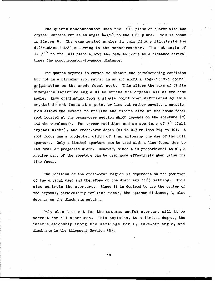
The quartz monochromator uses the 1011 plane of quartz with the
crystal surface cut at an angle 4-1/2 0 to the 1011 plane. This is shown
in Figure 9. The exaggerated angles in this figure illustrate the
diffraction detail occurring in the monochromator. The cut angle of
4-1/2 0 to the 1011 plane allows the beam to focus to a distance several
times the monochromator-to-anode distance.
The quartz crystal is curved to obtain the parafocussing condition
but not in a circular arc, rather in an arc along a logarithmic spiral
griginating on the anode focal spot. This allows the rays of finite
divergence (aperture angle a) to strike the crystal all at the same
angle. Rays originating from a single point when diffracted by this
crystal do not focus at a point or line but rather envelop a caustic.
This allows the camera to utilize the finite size of the anode focal
spot located at the cross-over section which depends on the aperture (a)
and the wavelength. For copper radiation and an aperture of 30 (full
crystal width), the cross-over depth (t) is 0.3 mm (see Figure 10). A
spot focus has a projected width of 1 mm allowing the use of the full
aperture. Only a limited aperture can be used with a line focus due to
its smaller projected width. However, since t is proportional to a 2 , a
greater part of the aperture can be used more effectively when using the
line focus.
The location of the cross-over region is dependent on the position
of the crystal used and therefore on the diaphragm (18) setting. This
also controls the aperture. Since it is desired to use the center of
the crystal, particularly for' line focus, the optimum distance, L, also
depends on the diaphragm setting.
Only when L is set for the maximum useful aperture will it be
correct for all apertures. This explains, to a limited degree, the
interrelationship among the settings for L, take-off angle, and
diaphragm in the Alignment Section (5).
10
The center of the diffraction circle is off-set from the main beam
by 300 and defined by the focal spot (F) at 220 mm from the
monochromator and a radius of 57 mm. The main beam passes through the
sample which is located tangentially to the diffraction circle. The 57
mm radius diffraction circle makes a linear distance of 2 mm on the
recording film equal to 10 20.
11

0 I0 0
riC)
( b C 4 -4U)j 0
CZ.C) _- AJ~
= CD
.Z CN
12

QUARTZ 101T PLANE
FOR CuKa 20=26.60
4.50
TRACE OF 10'1o ON SURFACE
Figure 9. Monochomator Detail.
13

00
"-4
"-4
CD 1=
uLLO% -iM L
V) CO rx.4
C..)OL
-m LU m U- to
14

4. SAFETY
The Guinier-Lenne camera, being an older instrument, has several
safety problems associated with it which will be discussed in this
section.
X-rays may be shut off by switching off the power to the tube or
with port safety shutters if the tube is so equipped. The G-L camera in
building 450 is set up on a General Electric XRD-5 generator which is
fitted with Supper safety shutters. Wearing a x-ray film badge is
required for operators of x-ray equipment and the use of a ring badge is
recommended, particularly when aligning this instrument. The instrument
should also be periodically surveyed for stray x-ray scattering.
The main x-ray beam was designed to pass through a metal bellows
(1), which now has been found to occasionally leak x-rays, and through
an open slot, Fl (3), after the monochromator. Both of these areas
should be covered with lead foil. The foil over the slot also prevents
anyone from inadvertently placing a finger in the beam path. During the
normal operation of this camera, the x-rays should be shut off whenever
the film cassette holder is removed. This holder not only holds the
recording film but also blocks the diffracted rays and main beam. The
main beam catcher also blocks the main beam but it is not interlocked to
close if the cassette holder is removed. The main beam window in the
cassette holder should be opened only during the alignment of the
camera.
Several times during the alignment procedure, the main x-ray beam
is open to the outside and accidental exposure to the operator is
possible. The operator should be aware of where the main x-ray beam is
coming from and where it is going while aligning the camera and avoid
those areas. Particularly dangerous is the situation when the film
cassette holder main beam window (34) is open. The operator may have to
move in front of the film cassette to shut off power to the tube. He
must first move the cassette holder vertically on its slide to block the
beam before moving to the control panel. The fluorescent screen used to
15
observe the beam image in the al~ignment section can be attached to a
stationary object or hand held when attached to 'a long (6 - 10 inch)
handle of wood or plastic.
5. ALIGNMENT
5.1 Preliminary Adjustments
These adjustments are all made with the x-ray generator off'.
5.1.1 Crystal Insertion - The quartz monochromator crystal (16)
must be carefully placed in the monochromator housing (2) as shown in
Figure 2. Note that the metal backing plate is on the side of' the
housing with the flat side and the hinged end of' the crystal is pointed
towards the side opposite the x-ray tube tower. The curvature dial (15)
is then turned inward (clockwise) until the screw just touches the
backing plate and then further until the scale (29) indicates the
approximate curvature for the target anode material used.
5.1.2 Camera Position - The parafocussing geometry discussed
earlier makes the positioning of the camera very important. The text of'
.this manual uses the values of' length and angles for copper radiation;
if a different radiation is used then substitute the appropriate length
and angle values from Table 1.
Determine the position of the anode target in the x-ray tube . For
General Electric CA-7 or CA-8 tubes, the anode position is in a plane
1-1/32 inches from the very top of the cooling head and centrally
located within the tube tower. Measure the take-off angle from that
position and plane. Move the entire camera by hand so that the center
of the monochromator housing is located at a take-off angle of 3 - 90
The larger the take-off angle, the greater the intensity and hence the
easier alignment, but with less resolution.
16

The distance from the center of the anode to the center of the
monochromator housing should be adjusted by moving the camera to L=110
mm. The flexible metal bellows should be clamped to the x-ray tube
shutter for safe operation of this camera. The position of the camera
housing foot beneath the monochromator housing should not be changed
again until the Final Adjustments Section (5.2).
The height of the camera is adjusted using the leveling nuts (14)
on the legs. The anode target, monochromator center, and film cassette
beam window should all be at the same height in a plane parallel to the
x-ray table.
Pivoting the camera, the angle between the x-ray anode target,
monochromator center, and film cassette beam window should be fixed at
the 20 angle for the 1011 quartz reflection of 26.60. These and some of
the other adjustments in this section can be done more easily by
removing the furnace (6) by loosening the screws on top of the heating
chamber and lifting it out of the way. The film cassette holder must be
removed first to gain access to the furnace.
The angle between the flat side of the monochromator housing and
the incident beam (Y) should be set at 90 using the monochromator
micrometer (21). The indicator scale (23) on the outside of the
monochromator housing should correspond approximately to the radiation
type being used. The monochromator is factory set for copper so other
radiation types require the housing to be changed.
To change the monochromator housing setting, loosen the lock screw
(25) under the housing and manually turn the housing to the desired
scale setting. Make sure the fine adjustment lever arm (22) rests
against the micrometer screw before re-tightening the housing lock
screw.
17
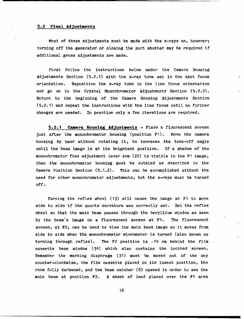
5.2 Final Adjustments
Most of these adjustments must be made with the x-rays on, however;
turning off the generator or closing the port shutter may be required if
additional gross adjustments are made.
First follow the instructions below under the Camera Housing
Adjustments Section (5.2.1) with the x-ray tube set in the spot focus
orientation. Reposition the x-ray tube in the line focus orientation
and go on to the Crystal Monochromator Adjustments Section (5.2.2).
Return to the beginning of the Camera Housing Adjustments Section
(5.2.1) and repeat the instructions with the line focus until no further
changes are needed. In practice only a few iterations are required.
5.2.1 Camera Housing Adjustments - Place a fluorescent screen
just after the monochromator housing (position Fl). Move the camera
housing by hand without rotating it, to increase the take-off angle
until the beam image is at its brightest position. If a shadow of the
monochromator fine adjustment lever arm (22) is visible in the F1 image,
then the monochromator housing must be rotated as described in the
Camera Position Section (5.1.2). This can be accomplished without the
need for other monochromator adjustments, but the x-rays must be turned
off.'
Turning the reflex wheel (13) will cause the image at F1 to move
side to side if the quartz curvature was correctly set. Set the reflex
wheel so that the main beam passes through the beryllium window as seen
by the beam's image on a fluorescent screen at Fl. The fluorescent
screen, at F2, can be used to view the main beam image as it moves from
side to side when the monochromator micrometer is turned (also known as
turning through reflex). The F2 position is -10 cm behind the film
cassette beam window (34) which also contains the toothed screen.
Remember the marking diaphragm (31) must be moved out of the way
counter-clockwise, the film cassette placed in its lowest position, the
room fully darkened, and the beam catcher (8) opened in order to see the
main beam at position F2. A sheet of lead placed over the F1 area
18

reduces the scattered radiation reaching your hands while making these
monochromator adjustments. The monochromator micrometer should be used
to produce a main beam image of maximum intensity; changes in the reflex
position may be required to maximize the image intensity.
If the distance L is correct, the image at F2 should appear
symmetrically from the sides and disappear in the middle or vice versa
when the camera is moved by the reflex wheel. If necessary, move the
camera by hand, again without rotating it, to get the correct length L.
For a line focus, the image at F1 is a narrow band. Position the
diaphragm (18) using handle (26) until it just cuts into the main beam
image and no separate lines are visible. The diaphragm may have to be
changed several times during the alignment.
If the image at F2 disappears top to bottom when the monochromator
micrometer is changed, then the height of the camera is incorrect. Use
the leveling nuts (14) to adjust the camera height until the problem is
corrected, maintaining the optical plane parallel to the x-ray table.
If the top to bottom movement of the image at F2 cannot be corrected
with the leveling nuts, the problem is probably in the x-ray tube
itself; i.e. the anode line focus is not vertical.
5.2.2 Crystal Monoehromator Adjustments - The camera must be
aligned well enough so that a fluorescent screen placed in the F2
position clearly shows the main beam.
Figure 11 shows the possible appearances of the beam image on the
fluorescent screen at F2. A rectangle is the desired shape of the
image. If the curvature of the quartz monochromator crystal is
incorrect the image will appear as a trapezoid. Turning the curvature
dial (15) slightly will vary the image from trapezoidal to rectangular
to trapezoidal. When the dial setting produces a rectangle, lock the
dial with its screw (28). A few trial exposures of the main beam should
be done at this point; open the beam catcher at minimal power for a few
seconds to expose film placed in the film cassette at several positions.
19

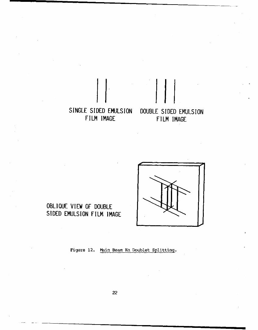
The Ka doublet should be clearly visible as diagramed in Figure 12 if
the curvature is correctly set.
The torsion on the quartz crystal should only have to be reset if
several crystals are being used. A small screw (19) must be adjusted so
that the image at F1 stays symmetric when the camera is moved through
its reflex. Access to this screw is through a hole (20) in the
monochromator housing. The monochromator housing must be closed when
the torsion is adjusted.
If the rectangle at F2 above is bowed at its top and bottom (see
Figure 11 d & e) the logarithmic curvature of the crystal is incorrect.
A set screw (28) can be loosened and slide (27) when moved slightly will
eliminate this bowing of the image.
Once these adjustments are made and the image is as close to a
rectangle as possible, the monochromator crystal need not be adjusted
again as long as the same radiation type is used. If all adjustments
are correct (i.e. final spot focus adjustments) the reflex wheel should
be turned until the image at F2 becomes triangular as the toothed screen
(34) begins to cut into the main beam image.
20

LLJLJ
LU
Le <.O/ Ci
- LL.JL
C-)LM 6-4>
LLJ .0-I
- LL.> >
0~
LU C) -j -jL
M. C) CDI-
C.DC-
w .' C) C-)
C) -:) I-C-:)LLIP LiII I
LL- .Li k: r.j24
I Ii I I I l •
SINGLE SIDED EMULSION DOUBLE SIDED EMULSIONFILM IMAGE FILM IMAGE
OBLIQOUE VIEW OF DOUBLESIDED EMULSION FILM IMAGE
Figure 12. Main Beam Ka Doublet Splitting.
22
6. OPERATION
Once the instrument is aligned a wide angle x-ray diffraction
pattern can be recorded photographically as a function of time or
several patterns may be recorded statically on the same piece of film.
Separate exposures at different temperatures may then be collected or a
continuous change in the sample's WAXD pattern may be obtained as a
function of temperature.
The x-ray generator, furnace cooling water (12), and control box
power must all be on before beginning a run. Once all runs are complete
these may be turned off.
6.1 Temperature Control
The starting and finishing temperatures are selected at the control
box (see Figure 13). The Low Temp Control Variac (36) sets the
temperature at the lower end of the desired range just as the High Temp
Control Variac (37) sets the upper end of the range. Figure 14 (from
reference 1) is the "setting selection chart". The higher temperature
is selected first and its variac set, then the lower temperature is set
as a percent of the higher temperature. For example, if you wanted to
set the temperature range from 4000 to 10000C, first the setting of 60%
would be dialed at the higher control and then 50% at the lower control
(4000C is a setting of 30% on the higher control which is one half of
60%). If zero is set for the lower end of the range then the lower
temperature is ambient. The Ranger Indicator Variac (38) is a motor
driven variac which indicates the differential voltage between the high
and low temperature variacs.
The starting temperature may be the lower or higher temperature by
the selecting "up" or "down" respectively on the Temp direction switch
(39). In either case the temperature will be raised to the starting
temperature before the timer begins. When the end temperature switch
(42) is in the "cyclus" position the power to the furnace will be shut
off at the end of the experiment, when it is in the "continuals"
23

position the final temperature is maintained until new settings are made
or the equipment shut down.
6.2 Time and Speed Selection
The length of time desired for the furnace to heat (or cool) the
sample from the starting temperature to the final temperature is
selected at the Time select switch (40). Discreet times of 0, 3, 4, 6,
12, 30, 40, 60, and 120 hours are available.
The speed of the film cassette must also be set. Speeds of 0.0,
0.5, 1.0, 1.5, 2.0, 5.0, 10.0, 15.0, and 20.0 mm/hour can be selected at
the Film speed switch (41). The zero speed is used for static
exposures. The speed selected is dependent on the length of the
experiment and the diffraction characteristics of the sample.
6.3 Sample Preparation
The sample can be placed in any holder that fits the frame (10 mm x
5 mm). A metal frame is available commercially as well as a metal
screen in a frame that powdered samples may be pressed into. Care must
be taken not to press too hard since these frames are made of a
deformable platinum-iridium alloy. In Figure 4 a solid polymer film is
shown while in the Appendix a film sample was wrapped around the
commercial frame that fits into the sample holder (5).
The sample can be mounted in the sample holder by either removing
the entire holder or by inserting the frames through the sample access
port (7).
Once the sample chamber is sealed, the environment can be set. The
sample can be run in air, vacuum, or with a sweep gas by connecting the
appropriate hoses to the Vacuum port (4).
24

6.4 Recording Film
Any type of x-ray sensitive film may be used. The size of the film
should be 174 mm wide and any length up to 260 mm. The film must be
loaded into the black paper film cassette in a darkroom and the cassette
loaded in its holder (9). The film should be wide enough so that one
edge is in the holder lip on the main beam side and extend out to
capture the entire region of interest. The length of the film should be
long enough to cover the entire experiment, depending on the time and
film speed.
Once the the temperatures have been set, the time and film speed
input, the sample mounted, and the film is in place the experiment can
begin. At selected points in the experiment, the film position can be
marked by moving the marking diaphragm (31) into position and
momentarily opening the main beam catcher (8). The marking diaphragm is
normally left out of position to avoid scatter and to allow the film to
obtain the lower angle region of the pattern.
Once exposed the film should be developed promptly according to the
standard procedures for that film. It can then be analyzed like any
cylindrical film remembering that every two millimeters of film
corresponds to 1 degree two theta. Several programs are available for
this analysis [4 & 5].
25

0
. . . .. . .0
26

80
7 0 y -- ----L H
60 H TEMP.: X %
L TEMP.: 1 x 100%50 x
40
30
20120 VOLT FURNACE
I0
0 I 2 3 4 5 6 7 8 9 10 11 12 13
TEMPERATURE (0C x 100)
Figure 14. Temperature Control Chart.
27

REFERENCES
01. "Guinier-Lenne Camera for High Temperatures up to 1200 C,
instructions for use," ENRAF-NONIUS, Delft, Holland (1966).
2. "Guinier-de Wolff Camera No. II, Operation Instructions," ENRAF-
NONIUS, Delft, Holland.
3. Ralph R. Eckstein, "Guinier-Lenne X-Ray Camera For High Temper-
atures Up To 1200 0 C - Revised Instructions," AEC Res. & Dev. Rpt.
MLM-1924, August 1972; Mound Laboratory, Monsanto Research
Corporation, Miamisburg, OH.
4. D. P. Anderson, "Documentation of "PHOTO": A User's Manual for the
Analysis of Photographic and X-ray Negatives," Tech. Rpt. AFWAL-TR-
84-4159, February 1985, Air Force Materials Laboratory, Wright-
Patterson Air Force Base, OH.
5. D. P. Anderson, "X-ray Analysis Software: Operation and Theory
Involved in Program DIFF," Tech. Rpt. AFWAL-TR-85-4079, June 1985,
Air Force Materials Laboratory, Wright-Patterson Air Force Base, OH.
6. S. R. Allen, "Mechanical and Morphological Correlations in Poly (p-
phenylenebenzobisthiazole) Fibers," Ph.D. Dissertation, University
of Massachusetts (Amherst), 1983.
7. I. Goldfarb, AFWAL/MLBP, Private Communications, June 1983.
8. D. P. Anderson, "High Temperature X-ray Study," Final Report for
Task 729-079, Universal Energy Systems, submitted to Dr. W. W.
Adams, AFWAL/MLBP, November 1983.
28

APPENDIX A
SAMPLE OPERATION RESULTS
29

Heat treatment is a commonly used technique for enhancing the
mechanical properties of polymeric fibers. This is of particular
interest to the Air Force in the ordered polymers area where fibers of
Polv(p-phenylenebenzobisthiazole) (PBT) have been found to dramatically
change on heat treatment [6]. This fiber was therefore chosen to test
the initial operation of the G-L camera described in the main text of
this report.
In this example the Guinier-Lenne camera was aligned according to
the instructions in this report and a sample was made of as-cast PBT
film wrapped around the open Pt-Ir frame. The film was oriented with
its machine direction (direction of chain orientation) vertical such
that the G-L camera would record the equatorial reflections of the fiber
(the G-L diffraction plane is horizontal).
The conditions of the experiment were to monitor the WAXD pattern
as the temperature was increased from ambient to near 6000 C and then
back to ambient in air. The low temperature variac was set at 0%, the
high temperature variac was set at 35%, the end temperature switch set
to "cyclus", and no vacuum or sweep gas was used. The temperature of
the sample holder was periodically checked with the built-in
thermocouple and a second thermocouple attached to the sample holder
frame; both thermocouples registered the same temperature within a few
degrees. Figure Al shows a plot of the temperature versus time during
this experiment.
A film speed of 15 mm/hr was selected to give an effective exposure
time of 4 minutes through the 1 mm wide diffraction slit. The time of
the experiment was set at 3 hours to get an average temperature increase
of 4°C/min. The film cassette was loaded with a fast Kodak DEF-5 x-ray
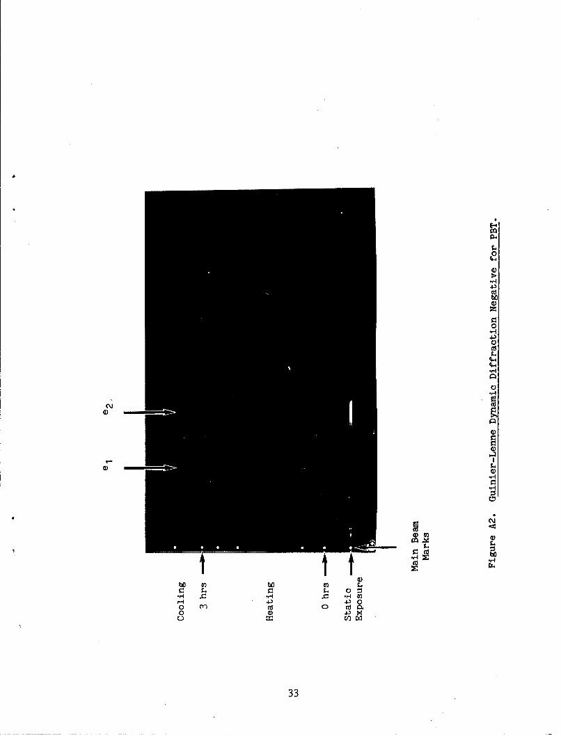
film to get a WAXD scan with as much intensity as possible. Figure A2
is a print of the film after exposure; main beam marks were placed at
various times as reference points.
30

The optical density of the film negative was digitized and analyzed
by program "PHOTO" [4]. The relative intensities plotted against Bragg
angle at several times are shown in Figure A3.
From these and other similar plots one can readily observe several
changes during the heating and cooling of this sample. The positions of
the two peaks (e1 and e 2 ) move to lower angles with increased
temperature corresponding to larger dimensions, due to thermal expansion
in the crystal since this change is reversible and occurs in heat
treated samples as well (example not shown). More important is the
dramatic increase in peak heights and narrowing of the peaks which
occurs around 3000C (see scans b, c, & d in Figure A3). The temperature
of this transition which is observed only when heating as-spun PBT,
occurs in the temperature range reported for a nonreversible second
order transition seen by DSC [7]. The annealing of the sample to form
more and larger crystals with greater degrees of perfection is a logical
explanation for this transition and has been suggested from other
studies [6].
One can conclude from this example [8] that crystal phase
transitions of even weakly scattering organic materials can be observed
by the Guinier-Lenne high temperature camera. Changes such as thermal
expansion are even easier to detect.
31

Cq
CNC)
L
LL.
pvlWd3 0a
322
E-4
$4
0
4.3ca
0)
0
r..0
C,
- N104
C\ I .
b¶ 03bo0.S
0 4)xo CO W.
33

U')LbJ CD
C)~~ -<C ) C :
C.. 0: 0. "0o C
Z _ a)
C-)
4J
W E-
C-C
U,
w
LC)0
-4
rx..
00*2 092 OO2 09A 00A 0G.0 00 C)'jklISN30 lIVDIIdO
314SU.S.Government Printing Office: 1986 - 646-067/40785