c922 (b - noventis
TRANSCRIPT

GDS404
OPERATING HANDBOOK
www.gds-technologies.co.uk
Tel. +44(0)113 286 0166
Fax. +44(0)113 287 8178
Email. [email protected]
C922 Manual No.: 43.D.1.C
Issue: C.v1
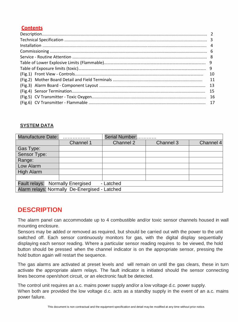
Contents Description............................................................................................................................................ 2
Technical Specification ......................................................................................................................... 3
Installation ........................................................................................................................................... 4
Commissioning ..................................................................................................................................... 6
Service - Routine Attention .................................................................................................................. 8
Table of Lower Explosive Limits (Flammable)………………….………………………………………………………………. 9
Table of Exposure limits (toxic)……………………………………………………………………………………………………….. 9
(Fig.1) Front View - Controls.......................................................................................…………………… 10
(Fig.2) Mother Board Detail and Field Terminals ............................................................................ 11
(Fig.3) Alarm Board - Component Layout .......................................................................................... 13
(Fig.4) Sensor Termination................................................................................................................. 15
(Fig.5) CV Transmitter - Toxic Oxygen................................................................................................. 16
(Fig.6) CV Transmitter - Flammable ................................................................................................... 17
SYSTEM DATA Manufacture Date:……………….. Serial Number:………… Channel 1 Channel 2 Channel 3 Channel 4 Gas Type: Sensor Type: Range: Low Alarm High Alarm
Fault relays: Normally Energised - Latched Alarm relays: Normally De-Energised - Latched
DESCRIPTION The alarm panel can accommodate up to 4 combustible and/or toxic sensor channels housed in wall mounting enclosure. Sensors may be added or removed as required, but should be carried out with the power to the unit switched off. Each sensor continuously monitors for gas, with the digital display sequentially displaying each sensor reading. Where a particular sensor reading requires to be viewed, the hold button should be pressed when the channel indicator is on the appropriate sensor, pressing the hold button again will restart the sequence.
The gas alarms are activated at preset levels and will remain on until the gas clears, these in turn activate the appropriate alarm relays. The fault indicator is initiated should the sensor connecting lines become open/short circuit, or an electronic fault be detected.
The control unit requires an a.c. mains power supply and/or a low voltage d.c. power supply. When both are provided the low voltage d.c. acts as a standby supply in the event of an a.c. mains power failure.
This document is non contractual and the equipment specification and detail may be modified at any time without prior notice.
Page: 2

TECHNICAL SPECIFICATIONS
(1) Power supply
- 230/115Vac 50/60Hz +/-15% (1A Fused Supply)
- 22~28Vdc (24Vdc Nominal)
- Normal operating condition = 3W
- Full alarm condition = 4.5W
- Optional 1-hour, 24V Battery backup (time based on running four-flammable channels) - (2) Sensor types
- Electrochemical /Infra Red – 4~20mA input
- Pellistor (F1/F6) direct mV Input
(3) Channels
- 1-4 Channels - Flammable / toxic / Oxygen
-
(4) Sensor Cable
- Flammable (catalytic) - 3 core, 1.5mm screened cable – maximum cable loop resistance 20 Ohms.
- Toxic/Oxygen – 2/3 core (see pages 16/17), 0.5 mm screened cable, – maximum cable loop resistance 200 ohms.
(5) Indication
- Backlit - 3 character - 7segment LCD
- Front Panel: ‘Power’ , ‘Fault’, ‘Alarms’ , ‘ Inhibit’ and ‘Gastype Motherboard: ‘DC output’ , ‘Channel active’, ‘Relay status’, and ‘alarm card fault’
(6) User Interface - 3 Buttons on front panel
(Test, Reset/Inhibit and Hold)
(7) Alarm settings - Each channel alarm card: Low, High, and fixed level Fault
(8) Tolerance - +/-5% Full Scale Display
- +/-2% Repeatability
(9) 404 Motherboard Outputs
- Common Low alarm relay - DPCO
Common High alarm relay - DPCO Common Fault relay - SPCO CH#1 relay - SPCO CH#2 relay - SPCO CH#3 relay - SPCO CH#4 relay - SPCO Global Sounder relay - SPCO - mutable in all state conditions ( Relays Lo, Hi and Fault - have the option to be latched or unlatched , energized or de-energised) Contacts - 5A @ 250vac (none inductive / capacitive)
(10) Audible - Mutable Buzzer on Motherboard
(11) Dimensions - (H) 265mm x (W) 315mm x (D) 80mm
(12) Enclosure
- Mild steel powder coat BS00A01
- IP52
- IP66 (optional over housing)
(13) Cable Entry - Bottom / Rear 20mm knock-outs
(14) Weight - 4Kg
(15) Operating Temperature - 5 - 40˚C
(16) Additional Features
- Overload Protection on DC out. (Healthy is indicated by Green LED). Fault will occur should fuse [F2] blow
- “Fuses - AC input, 24Vdc rail, Batteries and DC out
- Remote reset
Page: 3
Low or High
alarm selection
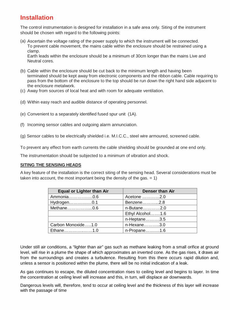
Installation The control instrumentation is designed for installation in a safe area only. Siting of the instrument should be chosen with regard to the following points:
(a) Ascertain the voltage rating of the power supply to which the instrument will be connected.
To prevent cable movement, the mains cable within the enclosure should be restrained using a clamp. Earth leads within the enclosure should be a minimum of 30cm longer than the mains Live and Neutral cores.
(b) Cable within the enclosure should be cut back to the minimum length and having been
terminated should be kept away from electronic components and the ribbon cable. Cable requiring to pass from the bottom of the enclosure to the top should be run down the right hand side adjacent to the enclosure metalwork.
(c) Away from sources of local heat and with room for adequate ventilation.
(d) Within easy reach and audible distance of operating personnel.
(e) Convenient to a separately identified fused spur unit (1A).
(f) Incoming sensor cables and outgoing alarm annunciation.
(g) Sensor cables to be electrically shielded i.e. M.I.C.C., steel wire armoured, screened cable. To prevent any effect from earth currents the cable shielding should be grounded at one end only.
The instrumentation should be subjected to a minimum of vibration and shock.
SITING THE SENSING HEADS
A key feature of the installation is the correct siting of the sensing head. Several considerations must be taken into account, the most important being the density of the gas. = 1)
Equal or Lighter than Air Denser than Air Ammonia………….….0.6 Acetone …………2.0 Hydrogen………….…0.1 Benzene………...2.8 Methane……………...0.6 n-Butane…………2.0
Ethyl Alcohol…….1.6 n-Heptane……….3.5 Carbon Monoxide…..1.0 n-Hexane………..3.0 Ethane…………..……1.0 n-Propane…….…1.6
Under still air conditions, a “lighter than air” gas such as methane leaking from a small orifice at ground level, will rise in a plume the shape of which approximates an inverted cone. As the gas rises, it draws air from the surroundings and creates a turbulence. Resulting from this there occurs rapid dilution and, unless a sensor is positioned within the plume, there will be no initial indication of a leak.
As gas continues to escape, the diluted concentration rises to ceiling level and begins to layer. In time the concentration at ceiling level will increase and this, in turn, will displace air downwards.
Dangerous levels will, therefore, tend to occur at ceiling level and the thickness of this layer will increase with the passage of time
Page: 4

Ventilation of the room will of course alter the situation significantly but it should be remembered that if the ventilator is not at ceiling level, a dangerous concentration can still occur between t he t op of t he ventilator and the ceiling.
For heavier than air gases such as propane or butane, the formation of dangerous layers occurs at ground level. These gases tend to behave like water and will run down gradients and pool at the lowest point.
The number of heads required in individual rooms is determined by the number of possible hazards in the vicinity.
Gas leakage may occur around valves, flanges and anywhere where gas pipes are jointed. It may be possible to cover several probable gas leaks in one room by the careful siting of a single head. Cable ducts, trenches and manholes are also likely places where a build up of heavy gases may collect.
When siting a head in such places it is most important to ensure that there is no likelihood of flooding by water, or excessive dust which may block the sintered disc and prevent gas reaching the sensor.
When monitoring gases outside, those lighter than air will be quickly dispersed, but gases heavier than air will tend to form in layers and again cause a dangerous hazard. When siting heads outside prevailing winds must be taken into consideration and adequate protection given against wind and rain.
POISONING OF CATALYTIC SENSORS
Catalytic elements used in flammable gas sensors are liable to be rendered inactive due to “poisoning” by certain groups of compounds.
In general contact with any gaseous compound capable of producing an involatile residue upon heating is to be avoided. Examples of such substances are: a. Silicon containing vapours as emitted by silicone polishes, greases and oils. b. Petroleum vapours containing tetra-ethyl lead or other organo-metallic compounds. c. Phosphorus in the form of phosphate esters.
These compounds will permanently affect the detector and if their presence is suspected the response of the detector should be determined by the calibration procedure.
It is also possible that the reaction of the detector to a flammable gas could be inhibited by halogen containing gases such as chloroform, carbon tetrachloride and Trichloro-ethylene. This effect is not permanent.
Page: 5
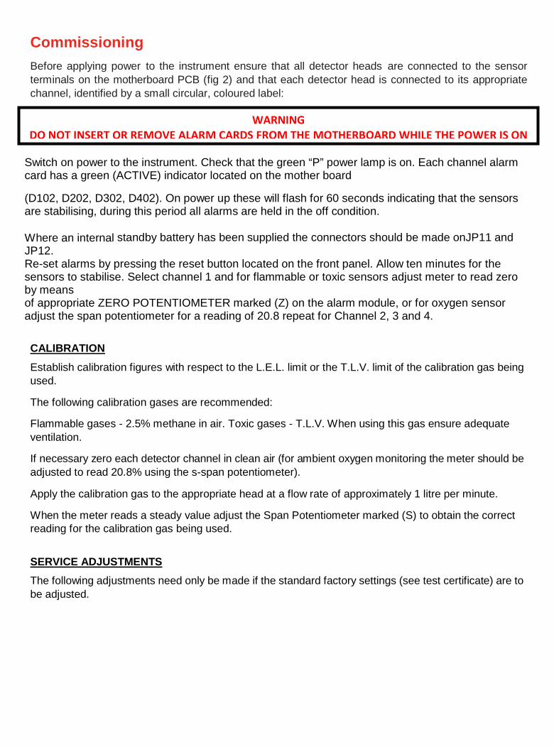
Commissioning Before applying power to the instrument ensure that all detector heads are connected to the sensor terminals on the motherboard PCB (fig 2) and that each detector head is connected to its appropriate channel, identified by a small circular, coloured label:
Switch on power to the instrument. Check that the green “P” power lamp is on. Each channel alarm card has a green (ACTIVE) indicator located on the mother board (D102, D202, D302, D402). On power up these will flash for 60 seconds indicating that the sensors are stabilising, during this period all alarms are held in the off condition. Where an internal standby battery has been supplied the connectors should be made onJP11 and JP12. Re-set alarms by pressing the reset button located on the front panel. Allow ten minutes for the sensors to stabilise. Select channel 1 and for flammable or toxic sensors adjust meter to read zero by means of appropriate ZERO POTENTIOMETER marked (Z) on the alarm module, or for oxygen sensor adjust the span potentiometer for a reading of 20.8 repeat for Channel 2, 3 and 4.
CALIBRATION
Establish calibration figures with respect to the L.E.L. limit or the T.L.V. limit of the calibration gas being used.
The following calibration gases are recommended: Flammable gases - 2.5% methane in air. Toxic gases - T.L.V. When using this gas ensure adequate ventilation.
If necessary zero each detector channel in clean air (for ambient oxygen monitoring the meter should be adjusted to read 20.8% using the s-span potentiometer).
Apply the calibration gas to the appropriate head at a flow rate of approximately 1 litre per minute.
When the meter reads a steady value adjust the Span Potentiometer marked (S) to obtain the correct reading for the calibration gas being used.
SERVICE ADJUSTMENTS
The following adjustments need only be made if the standard factory settings (see test certificate) are to be adjusted.
Page: 6
WARNING
DO NOT INSERT OR REMOVE ALARM CARDS FROM THE MOTHERBOARD WHILE THE POWER IS ON

CALIBRATION WHEN USING TRANSMITTER (4~20mA DEVICE) Where a sensor 4~20mA transmitter has been supplied the setting up procedure as described in fig:5 or 6 should be followed. The standard transmitter for toxic sensors is supplied as a two wire device set in a loop powered mode, and the flammable sensor is supplied as a three wire device.
NOTE: Where a 4~20mA transmitter is used, adjustment of the alarm module calibration potentiometer is not required (factory set for 4~20mA input signals), gas calibration need only be carried out at the detector head end. Connecting a mV meter across the 4~20mA input test pins (see fig.2 #28), will provide a sensor input signal voltage readingequal to the mA value (4mV=4mA).
ALARM LEVELADJUSTMENT
1.Alarm levels may be adjusted as follows: For toxic/flammable gases zero the instrument in clean air using the zero potentiometer (for ambient oxygen monitoring the meter should be adjusted to read 20.8 using the s-span potentiometer). 2.Press the alarm set switch for approximately 5 seconds the sounder will bleep and the low alarm indicator will come on, the green power indicator will turn off, release the alarm switch. 3.Using the zero potentiometer adjust the digital display for the required low trip level reading, press the alarm set switch until the high alarm indicator comes on, release the alarm set switch. 4.Adjust the digital display to read the required high trip level reading and again press the alarm set switch both alarm indicators will come on. 5.Zero the digital display (toxic/flammable) or 20.8 for oxygen and press alarm set switch, alarm indicators will turn off and the green power indicator will turn on.
SENSOR SUPPLY ADJUSTMENT (CATALYTIC SENSOR)
Factory set – no further adjustment required unless a change of sensor type is being made. Sensor supply is delivered from a constant current source and is measured in mV across a 1Ω resistor. Therefore connecting a digital voltmeter (mV setting) across the SV (2) test point of the alarm card (fig.3) and 0V (#29) on the motherboard (fig.2) will provide a mV reading equal to the current being drawn (4mV=4mA). Adjustment may be carried out using the sensor supply adjustment potentiometer (fig.3 #3) Example: Sensor type CAT300A = 300mA. 4-20mA OUTPUT ADJUSTMENT
Adjustments: With the load connected to the appropriate 4~20-mA output terminal (typically 100 ohms) and a digital volt meter connected to the test pins TP3 + TP4 see fig 3(20) ensure that the sensor is in clean air, and that the instrument is reading zero.
Adjust the 4mA potentiometer to read 4mV (=4mA) on the digital voltmeter. Using the appropriate sensor zero potentiometer adjust the alarm panel digital display for full scale reading.
Adjust the 20mA output potentiometer until the digital voltmeter reads 20mV (=20mA) Return the alarm panel digital display reading to zero by readjusting the zero potentiometer.
Page: 7

RANGE & SCALE SELECTION The range and scale reading is normally factory set but where a sensor alarm board is to be added the following selections should be made on the display board PCN037.
Note: Power to the system should be off when insert ing or removing an alarm card.
1 Range - for the appropriate channel select %L.E.L., %Vol. or PPM range by connecting the jumper across the indicated selector pins.
2 Scale - Select the scale required by connecting the jumper across the appropriate DP pins. No jumper - Digital panel meter reading 100
DP1 - Digital panel meter reading 10.0 DP2 - Digital panel meter reading 1.00
Service – Routine Attention
The owner or occupier of the premises should place the supervision of the system in the charge of a responsible executive whose duty it should be to ensure the day to day operation of the system and to lay down the procedure for dealing with a gas alarm or fault warning. To ensure reliability an agreement should be negotiated for regular servicing. When a service contract cannot be arranged an employee with suitable experience of electrical equipment should be trained to deal with the more simple servicing and instructed not to attempt to exceed the scope of such training.
Liaison should be established with those responsible for maintenance of the building fabric or redecoration etc. to ensure that their work does not cause a fault or otherwise interfere with the operation of the gas alarm installation.
The operating instructions should be kept available preferably with the control unit, all faults, service tests and routine attention given should be recorded.
DAILY: A check should be made that any fault condition which may be indicated is in fact being attended to and that all other indicators are normal.
WEEKLY : In plants involving a high risk process or having gases which may cause loss of sensitivity a check on calibration should be carried out.
TWICE YEARLY MAINTENANCE SCHEDULE
1 All zeros at the control unit to be checked, logged and aligned. 2 Each detector to be gas tested and reading logged (sensitivity checked). 3 Field indicators to be tested. 4 All alarm set points checked and re-aligned. 5 Lamp Test. 6 All faulty parts replaced where required. 7 All filter elements checked and replaced as necessary. 8 Power supply - complete functional check. 9 Visual inspection made to confirm that all cabling fitting and equipment is secure, undamaged and
adequately protected. ACTION TO BE TAKEN IF THE APPARATUS ALARM SOUNDS:
Extinguish all naked flames, including all smoking materials. Turn off all gas appliances. Do not switch on or
off any electrical lights or appliances. Turn off the gas supply at the gas emergency control.
Open doors and windows to increase ventilation
Page: 8

Table of lower explosive limits - L.E.L.
GAS L.E.L. (% VOLUME) Acetone ........................................................................................................2.1
Ammonia ....................................................................................................15.0
Benzene ........................................................................................................1.2
n-Butane .......................................................................................................1.5
Carbon monoxide........................................................................................12.5
Ethylene ....................................................................................................... 2.7
Heptane ....................................................................................................... 1.1
Hexane ........................................................................................................ 1.2
Hydrogen ..................................................................................................... 4.0
Methane ...................................................................................................... 5.0
Propane ........................................................................................................2.0
Pentane........................................................................................................ 1.4
Toluene ....................................................................................................... 1.2
Xylene ..........................................................................................................1.0
Table of occupational exposure limits - P.P.M. The figures quoted below are taken from guidance note EH40 from t he Health and Safety Executive.
GAS P.P.M (LTEL) Hydrogen Sulphide ..............................................................................................5
Carbon monoxide ..............................................................................................30
Sulphur dioxide ....................................................................................................2
Nitrogen monoxide ............................................................................................25
Nitrogen dioxide ..................................................................................................3
Chlorine ............................................................................................................0.5
Ammonia............................................................................................................25
Ozone ...............................................................................................................0.1
Ethylene oxide ....................................................................................................5
Page: 9

(Fig 1) FRONT PANEL DETAIL
FRONT REAR
(1) Range Indicators
Channel selectable by jumper
%LEL = Lower explosive Level , ppm = Parts per Million, %Vol = %Volume
(2) LCD
3-digit, backlit 7-segment display.
The unit can be backlit by selecting the jumper on the rear of the front panel
Each channel range decimal is selected by jumpers on the rear of the front panel.
(3) Channel Active LED (C1, C2, C3, C4) (Yellow LED)
The front panel scrolls through all active channels at 5 second intervals.
Note that the range indicator changes with channel active according to jumper settings on the rear back of the front panel
(4) “Low” Alarm (Red) LEDs
The alarm levels are Set on the Alarm card itself
If a specific channel enters Low alarm the Channel specific Low alarm LED will flash, and the sounder on the motherboard will activate.
To mute the sounder press ‘reset’
If alarm conditions are still present the Lo alarm will no longer flash, but stay permanently on. The sounder will deactivate, and
associated relays will remain latched.
Only when conditions are below the low alarm threshold, will relays and LED turn off when reset.
(5) “High” Alarm (red) LEDs
Same as (4), but for the high alarm
(6) Test Switch
When pressed and held for 15 seconds the control unit test mode is actioned.
During test, the panel scrolls through each channel Low / High LEDs, and the sounder.
Holding the test switch down for a further 15 seconds will cause the alarm relays to activate
(7) Reset Switch / Alarm relay Inhibit
Used to mute the sounder, and reset LEDs if no gas is present.
Pressing and holding reset for 15 seconds will inhibit the alarm relays which are indicated by the fault light illuminating.
To remove the inhibit press the reset pad for 15 seconds, at which, the fault light will turn off.
(8) Hold Switch
Pressing and releasing “hold” will hold the LCD display on a particular sensor channel (indicated by the yellow LED). Press again to
continue the auto scroll
(9) Fault / Inhibit (Yellow) LED (F)
Illuminates as a “fault” in the event of the control unit not detecting a sensor input with an alarm card in place.
Also illuminates to show that the unit is in “inhibit mode”.
By examining the alarm card LEDs the user can determine whether it is a fault or inhibit, and which channel caused it (described under
the alarm card section)
(10) Dual Colour Power LED (P)
Green = Mains supply present (230/110V)
Red = Mains supply is not present and the control unit is either running on DC supply, or the internal battery.
Page: 10
(3)
(5)
(7) (6) (8)
(10)
(1)
(2)
(4)
(9)

(Fig.2) MOTHERBOARD DETAIL
(1) 24Vdc Input Terminal
(2) 24Vdc Output Terminal
(3) 24Vdc Output LED (On - Healthy)
(4) 24Vdc rail Fuse (F3) – 1A (Anti-surge)
(5) 24Vdc Output Fuse (F2) – 315mA (Anti-surge)
Please note that - should the fuse blow, LED-D22 (3), will turn off, and the panel will enter fault mode.
(6) Alarm Card Slot (x4 Channels)
(7) Battery Output Fuse (F4) – 1A (Anti-surge)
(8) Battery Terminals
Page: 11
(4)
(1) (2) (3)
(5)
(6) (7) (8) (9) (10) (11)
(12)
(13)
(14)
(15)
(16) (17)
(18)
(19)
(20)
(21) (22) (23) (24)
(25) (26) (27)
(28)
(29)

(9) Sounder ‘Mute’ link (permanent)
(10) Global relay indication LED (Lo/Hi/Fault alarms)
Illuminated when energised
(11) Global relay Output Terminal
(12) Mains input Voltage select switch 230/110 – Factory selected 230V.AC
(13) Front panel Ribbon cable box header
(14) Remote reset input terminal (N/O)
(15) Low/High/Fault Relay selection.
Determines the relay status – Energised/De-energised for Low, High and Fault relays
(16) ‘Channel active’ LED (x4 channels)
Flashes green for the first 60 seconds during ‘warm-up’. Solid green there after.
(17) Earth terminal
Sensor cable Earth point
(18) Mains Input Fuse (F1) – 315mA (Anti-surge)
(19) Relay status indication LED (x7)
Illuminated when energised
(20) Alarm Set switch (x4 Channels)
Used to set each channel alarm trip points – (low/High Alarms)
(21) Mains input terminal – Live, Neutral, Earth – (see Installation , page 4)
(22) Global ‘Low’ relay terminal
(23) Global ‘High’ relay terminal
(24) Global ‘Fault’ relay terminal
(25) Channel alarm relay terminal (x4 channels) – Low/High alarm selectable
(26) Sensor input terminal (x4 channels)
(27) 4~20mA output terminal (x4 channels)
(28) 4~20mA sensor input test points (x4 channels)
(29) 0V DC Test point
Page: 12

(FIG.3) ALARM CARD DETAIL
DO NOT INSERT OR REMOVE ALARM CARDS WITH THE POWER ON.
(1) Sensor Current (Flammable cards only)
Used to select Sensor current depending on the pellistor used.
Low: 50mA to 200mA (example VQ41’s, F6’s)
High: 201mA to 400mA (e.g. CAT300A/CAT335A)
(2) Sensor Voltage test point - SV - (reference to 0V) – (flammable cards only)
Used in conjunction with a multimeter (mV range) to calibrate the sensor current (see 3)
(3) Sensor Voltage Potentiometer – (flammable cards only)
Used to adjust the sensor current following low/high selection (see 1)
(4) Zero Potentiometer
Used to adjust the sensor display zero reading .
Note: for zeroing gas which is present in air (such as Oxygen),an inert gas must be applied to the sensor first (i.e. N2)
(5) Calibration (Span) potentiometer
Used to adjust the sensor gas reading
Note: when spanning, the target gas should be applied
(6) DPM potentiometer
Used to calibrate the LCD to Full scale Display reading (factory set)
(7) 20mA output potentiometer
Used to Calibrate 20mA output signal
(8) 4mA output potentiometer
Used to Calibrate 4mA output signal
(9) Calibration test points
Used to calibrate the 0.5V at Full Range during setup (factory set)
(10) Low/High Channel relay - trip
Selects whether the channel relay triggers at low or high alarm levels
Page: 13
(13) (15) (17)
(2) (3) (4) (8) (7) (6) (5) (12)
(10)
(9)
(11)
(13)
(14)
(15)
(16)
(17)
(18)
(1)
(21) (19)
(20)
(22)

(11) Low/High channels relay status
Energised/DeEnergised selection
(12) ‘FS’ Header
Only used when the alarm card is used with a ‘Flow Sample’ system (factory set)
(13) ‘T2’ Header
30 Seconds time delay to alarm relay trip.
Note: the alarm card must be in alarm state for the full 30 seconds before the relays change state
(14) ‘T1’ Header
10 Seconds time delay to alarm relay trip.
Note: the alarm card must be in alarm state for the full 10 seconds before the relays change state
(15) ‘LL’ Header
Used to create two Falling alarms (Low/Low) for gasses such as Oxygen depletion
Note: the header “O2” should also be in the lower position.
(16) ‘O2’ Header
Used to create one low going alarm, and one high going alarm. (oxygen depletion/enrichment alarm)
(17) ‘RES’ Header (Alarm Reset)
“manual” or Automatic”
Determines whether “reset” on the front panel must be pressed by an operator, or whether the control until automatically
resets the LEDs when the alarm falls below the trip points.
(18) ‘P/24’ Header
24 = Used for Toxic alarm cards – Sets sensor supply to 24VDC
P = Used for Flammable alarm cards – constant current drive (see 2 and 3) - Pellistor
(19) ‘Output’ Header
Determines whether the 4~20mA output terminal on the motherboard (27) is analogue 4~20mA, or digital 1-5VDC
(20) ‘Output 4~20mA’ – Test Pins
Used to calibrate the ‘4~20mA output’ signal during setup (mV across test pins = mA)
(21) Fault LED
Indicates whether the channel is in Fault, caused by the alarm card no longer detecting a sensor input.
Note: this LED may be used to determine which individual channel has caused the global front panel fault LED to illuminate
(22) Inhibit LED
Upon performing global alarm relay inhibit procedure, all connected alarm cards should have their “inh.” LED illuminated.
Useful to confirm that all channels are indeed inhibited before system service.
Page: 14

(Fig.4) Page: 15

(Fig.5)
Page: 16

(Fig.6)
Page: 17