c9.3 project guide 2015 lebm0048-00 - 中華機械€¦ · elements are reusable when cleaned with...
TRANSCRIPT
Cat® C9.3 MARINE PROJECT GUIDE
U.S. EPA TIER 3/IMO II COMPLIANT
CAT C9.3 MARINE PROJECT GUIDE
Page 2 of 44
General ........................................................................................................ 4 C9.3 Engine Information ........................................................................................... 4 Product Identification Information .......................................................................... 4
Air System .................................................................................................. 7 Engine Protection Strategy ...................................................................................... 7 Air Cleaner ................................................................................................................. 7 Crankcase Fumes Disposal ...................................................................................... 7 Crankcase Piping System ......................................................................................... 8
Cooling System .......................................................................................... 8 Introduction ............................................................................................................... 8 Coolant Temperature Control .................................................................................. 8 Jacket Water Pump .................................................................................................. 8 Auxiliary Water Pump .............................................................................................. 8 Heat Exchanger Cooled Engines ............................................................................. 9
Seawater Flow Restriction .................................................................................. 9 Venting ................................................................................................................. 9 Coolant Connections ......................................................................................... 10 Engine Bonding System .................................................................................... 11
Keel Cooled Engines ............................................................................................... 13 Coolant Flow Control ......................................................................................... 13 Venting ............................................................................................................... 13 Separate Circuit Cooling ................................................................................... 15 Coolant Connections ......................................................................................... 16 Combined Circuit Cooling ................................................................................. 17 Coolant Connections ......................................................................................... 18
Cold Starting (Jacket Water Heaters) ................................................................... 20 Water Quality, Rust Inhibitors, and Antifreeze .................................................... 21 Coolant Heat Recovery ........................................................................................... 21
Exhaust System ....................................................................................... 21 Exhaust Backpressure Limits ................................................................................. 21 Turbochargers ......................................................................................................... 22 Exhaust Piping ........................................................................................................ 22
Fuel System .............................................................................................. 23 Introduction ............................................................................................................. 23 Tank Position ........................................................................................................... 23 Line Restriction ....................................................................................................... 23 Fuel Cooler ............................................................................................................... 24 Fuel Connections .................................................................................................... 24 Fuel Filters ............................................................................................................... 26 Fuel Priming Pumps ................................................................................................ 27 Common Rail ........................................................................................................... 29 Drip Trays ................................................................................................................ 29
CAT C9.3 MARINE PROJECT GUIDE
Page 3 of 44
Lubrication Oil System ............................................................................ 30 General ..................................................................................................................... 30 Oil Pan ...................................................................................................................... 30 Oil Filters .................................................................................................................. 30
Remote Mount Duplex Oil Filters ..................................................................... 30 Drip Trays ................................................................................................................ 32 Transmission Oil Cooler ......................................................................................... 33
Power Take Offs ....................................................................................... 33 Front Stub Shaft ..................................................................................................... 33 Belt Drive ................................................................................................................. 33
Starting System ....................................................................................... 33 Electric Starter ........................................................................................................ 33 Air Starter ................................................................................................................ 34
Air Pressure, Quality, and Filtration ................................................................. 34 Lubrication ......................................................................................................... 34 Emergency Starting ........................................................................................... 34
Dual Start ................................................................................................................. 35
Charging System ...................................................................................... 36
Mounting System .................................................................................... 36 Isolator Mounts ....................................................................................................... 36
Electronic System .................................................................................... 36 Sensor Architecture ................................................................................................ 36 Programmable Monitoring System ...................................................................... 37 Engine Harness Breakouts Connector Locations ................................................. 37 Customer Connection and J1939 .......................................................................... 40 Panels ....................................................................................................................... 41 Displays .................................................................................................................... 41
Hardware Summary ................................................................................. 41
Engine Preservation and Packaging ....................................................... 41
Shipbuilder’s Responsibility ................................................................... 42
Reference Material ................................................................................... 43
CAT C9.3 MARINE PROJECT GUIDE
Page 4 of 44
General
C9.3 Engine Information The C9.3 is certified to U.S. EPA Tier 3 and IMO II Marine commercial emissions standards for propulsion applications and 60 Hz auxiliary applications. The C9.3 is only certified to IMO II emissions standards for 50 Hz auxiliary applications.
All propulsion application engines are certified to EU Stage IIIA and EU Recreational Craft Directive E3 cycle standards. All fixed and variable speed auxiliary application engines are certified to CCNR Stage II standards.
The Reference Materials section at the end this guide provides links to Power Net and other resources for additional information.
Product Identification Information Marine Propulsion High Performance and Variable Speed Auxiliary (C9.3 MP3G)
U.S. EPA Tier 3 / IMO II Engine E-Model: EE290
U.S. EPA Tier 3 / IMO II Engine S/N Prefix: CP9
Marine Constant Speed Auxiliary and Gen Set Engine (C9.3MGE3G)
U.S. EPA Tier 3 / IMO II Engine E-Model: EE291
U.S. EPA Tier 3 / IMO II Engine S/N Prefix: CA9
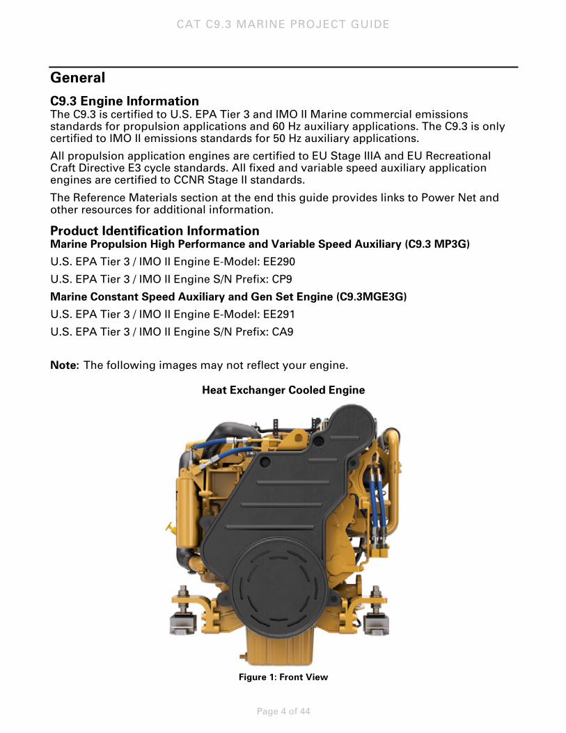
Note: The following images may not reflect your engine.
Heat Exchanger Cooled Engine
Figure 1: Front View
CAT C9.3 MARINE PROJECT GUIDE
Page 5 of 44
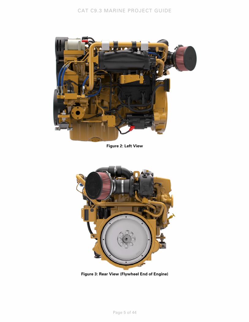
Figure 2: Left View
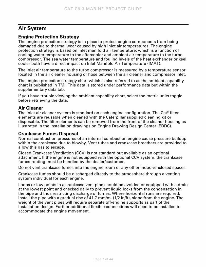
Figure 3: Rear View (Flywheel End of Engine)

CAT C9.3 MARINE PROJECT GUIDE
Page 6 of 44
Figure 4: Right View
CAT C9.3 MARINE PROJECT GUIDE
Page 7 of 44
Air System
Engine Protection Strategy The engine protection strategy is in place to protect engine components from being damaged due to thermal wear caused by high inlet air temperatures. The engine protection strategy is based on inlet manifold air temperature; which is a function of cooling water temperature to the aftercooler and ambient air temperature to the turbo compressor. The sea water temperature and fouling levels of the heat exchanger or keel cooler both have a direct impact on Inlet Manifold Air Temperature (IMAT).
The inlet air temperature to the turbo compressor is measured by a temperature sensor located in the air cleaner housing or hose between the air cleaner and compressor inlet.
The engine protection strategy chart which is also referred to as the ambient capability chart is published in TMI. This data is stored under performance data but within the supplementary data tab.
If you have trouble viewing the ambient capability chart, select the metric units toggle before retrieving the data.
Air Cleaner The inlet air cleaner system is standard on each engine configuration. The Cat® filter elements are reusable when cleaned with the Caterpillar supplied cleaning kit or disposable. The filter elements can be removed from the front of the cleaner housing as illustrated in the installation drawings on Engine Drawing Design Center (EDDC).
Crankcase Fumes Disposal Normal combustion pressures of an internal combustion engine cause pressure buildup within the crankcase due to blowby. Vent tubes and crankcase breathers are provided to allow this gas to escape. Closed Crankcase Ventilation (CCV) is not standard but available as an optional attachment. If the engine is not equipped with the optional CCV system, the crankcase fumes routing must be handled by the dealer/customer. Do not vent crankcase fumes into the engine room or any other indoor/enclosed spaces.
Crankcase fumes should be discharged directly to the atmosphere through a venting system individual for each engine.
Loops or low points in a crankcase vent pipe should be avoided or equipped with a drain at the lowest point and checked daily to prevent liquid locks from the condensation in the pipe and thus restricting discharge of fumes. Where horizontal runs are required, install the pipe with a gradual rise of 41.7 mm/m, (1/2 in/ft), slope from the engine. The weight of the vent pipes will require separate off-engine supports as part of the installation design. Further additional flexible connections will need to be installed to accommodate the engine movement.
CAT C9.3 MARINE PROJECT GUIDE
Page 8 of 44
Crankcase Piping System Vent the pipe out of the vessel directly into the atmosphere at a well-considered location fitted with a gooseneck or similar arrangement to keep rain or water spray from entering the engine. Consideration should also be given to other equipment located near the discharge area. If not located properly, the oil carryover can accumulate over time and become unsightly.
An oil condensate trap will minimize the amount of oil discharged from the vent pipe.
Cooling System
Introduction The C9.3 commercial propulsion and auxiliary engine has two cooling system options: heat exchanger cooling and keel cooling. Both separate circuit and combined circuit keel cooling options are available. The heat exchanger cooling system is identified as Sea Water Aftercooled (SWAC) system.
Sacrificial anodes are not included on this product. This engine is designed to be used with a zinc bonding system, where the zinc is installed on the vessel. Additional information is provided in the bonding section below.
Coolant Temperature Control The SWAC engines use outlet control temperature regulator/thermostat to provide uniform coolant temperature to the jacket water circuit. There is no temperature control required on the aftercooler circuit. The parameters of the jacket water thermostat are given below:
• Opening temperature: 81°C – 84°C (178°F – 183°F)
• Fully open temperature: 92°C (198°F)
Jacket Water Pump The C9.3 commercial propulsion and auxiliary engines have one belt-driven centrifugal water pump mounted on the right side of the engine (viewed from the flywheel end). This jacket water pump supplies coolant to the oil cooler, water-cooled manifold, turbocharger, block, and head.
Auxiliary Water Pump The C9.3 commercial propulsion and auxiliary engines have one gear-driven auxiliary water pump which supplies water to the fuel cooler (if equipped), aftercoooler, gear/transmission oil cooler (if equipped,) and jacket water heat exchanger (if equipped). This may also be referred to as the sea water pump on heat exchanged engines. This is a self-priming, rubber impeller pump. The maximum lift capability of the pump is 3 meters (10 feet). Pump performance data is published in TMI under component data. Some systems may require an auxiliary priming system to meet the application requirements.
The auxiliary water pump is mounted on the left side of the engine (viewed from the flywheel end) and is supplied as standard equipment on all engines regardless of cooling system.
CAT C9.3 MARINE PROJECT GUIDE
Page 9 of 44
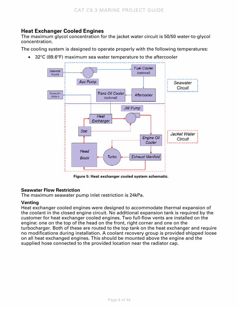
Heat Exchanger Cooled Engines The maximum glycol concentration for the jacket water circuit is 50/50 water-to-glycol concentration.
The cooling system is designed to operate properly with the following temperatures:
• 32°C (89.6°F) maximum sea water temperature to the aftercooler
Figure 5: Heat exchanger cooled system schematic.
Seawater Flow Restriction The maximum seawater pump inlet restriction is 24kPa.
Venting Heat exchanger cooled engines were designed to accommodate thermal expansion of the coolant in the closed engine circuit. No additional expansion tank is required by the customer for heat exchanger cooled engines. Two full-flow vents are installed on the engine: one on the top of the head on the front, right corner and one on the turbocharger. Both of these are routed to the top tank on the heat exchanger and require no modifications during installation. A coolant recovery group is provided shipped loose on all heat exchanged engines. This should be mounted above the engine and the supplied hose connected to the provided location near the radiator cap.
CAT C9.3 MARINE PROJECT GUIDE
Page 10 of 44
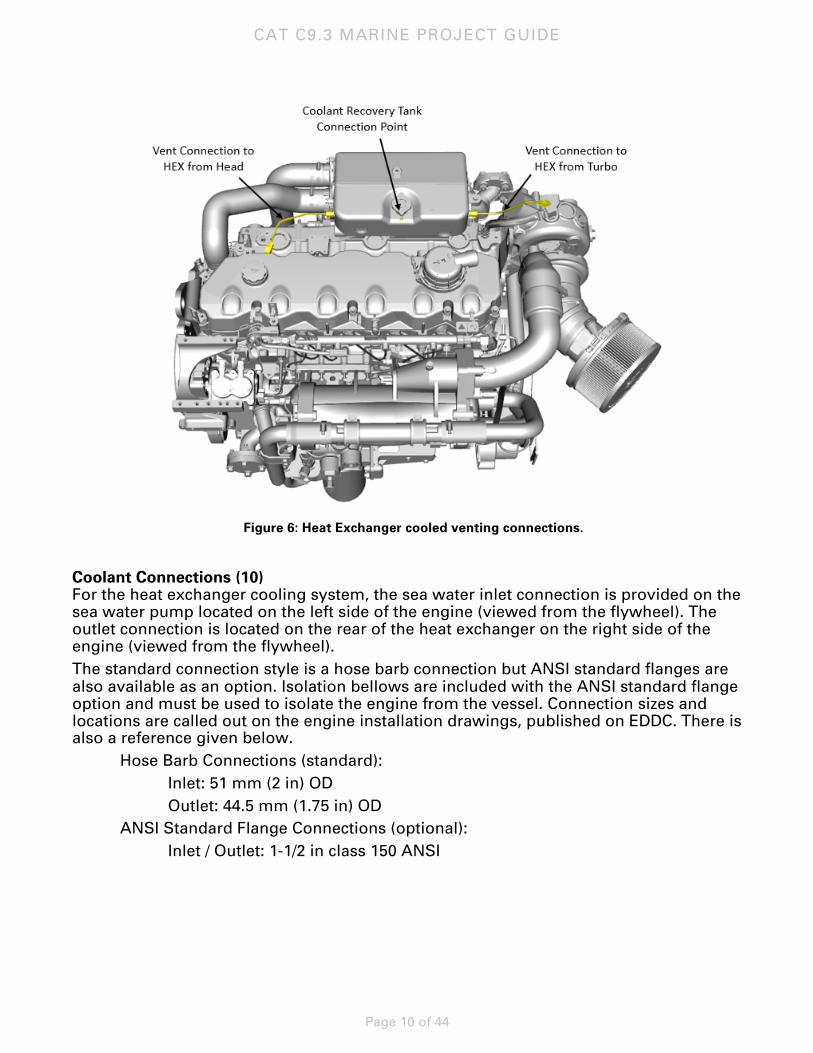
Figure 6: Heat Exchanger cooled venting connections.
Coolant Connections (10) For the heat exchanger cooling system, the sea water inlet connection is provided on the sea water pump located on the left side of the engine (viewed from the flywheel). The outlet connection is located on the rear of the heat exchanger on the right side of the engine (viewed from the flywheel). The standard connection style is a hose barb connection but ANSI standard flanges are also available as an option. Isolation bellows are included with the ANSI standard flange option and must be used to isolate the engine from the vessel. Connection sizes and locations are called out on the engine installation drawings, published on EDDC. There is also a reference given below.
Hose Barb Connections (standard): Inlet: 51 mm (2 in) OD Outlet: 44.5 mm (1.75 in) OD ANSI Standard Flange Connections (optional): Inlet / Outlet: 1-1/2 in class 150 ANSI
CAT C9.3 MARINE PROJECT GUIDE
Page 11 of 44
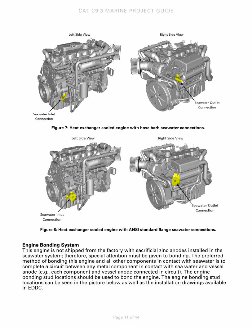
Figure 7: Heat exchanger cooled engine with hose barb seawater connections.
Figure 8: Heat exchanger cooled engine with ANSI standard flange seawater connections.
Engine Bonding System This engine is not shipped from the factory with sacrificial zinc anodes installed in the seawater system; therefore, special attention must be given to bonding. The preferred method of bonding this engine and all other components in contact with seawater is to complete a circuit between any metal component in contact with sea water and vessel anode (e.g., each component and vessel anode connected in circuit). The engine bonding stud locations should be used to bond the engine. The engine bonding stud locations can be seen in the picture below as well as the installation drawings available in EDDC.
CAT C9.3 MARINE PROJECT GUIDE
Page 12 of 44
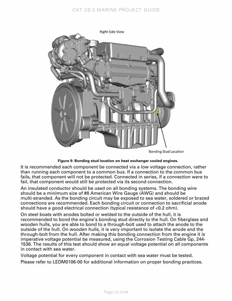
Figure 9: Bonding stud location on heat exchanger cooled engines.
It is recommended each component be connected via a low voltage connection, rather than running each component to a common bus. If a connection to the common bus fails, that component will not be protected. Connected in series, if a connection were to fail, that component would still be protected via its second connection. An insulated conductor should be used on all bonding systems. The bonding wire should be a minimum size of #8 American Wire Gauge (AWG) and should be multi-stranded. As the bonding circuit may be exposed to sea water, soldered or brazed connections are recommended. Each bonding circuit or connection to sacrificial anode should have a good electrical connection (typical resistance of <0.2 ohm). On steel boats with anodes bolted or welded to the outside of the hull, it is recommended to bond the engine’s bonding stud directly to the hull. On fiberglass and wooden hulls, you are able to bond to a through-bolt used to attach the anode to the outside of the hull. On wooden hulls, it is very important to isolate the anode and the through-bolt from the hull. After making this bonding connection from the engine it is imperative voltage potential be measured, using the Corrosion Testing Cable Gp, 244-1536. The results of this test should show an equal voltage potential on all components in contact with sea water. Voltage potential for every component in contact with sea water must be tested. Please refer to LEDM0106-00 for additional information on proper bonding practices.
CAT C9.3 MARINE PROJECT GUIDE
Page 13 of 44
Keel Cooled Engines The maximum glycol concentration for the jacket water and aftercooler circuits is 50/50 water-to-glycol concentration.
A coolant level sensor can be supplied as optional on keel cooled engines. When equipped, this is a shipped-loose sensor that should be installed in the vessel-mounted expansion tank. A jumper harness is also included and a dedicated breakout is located on the engine harness. Refer to the electronics section for additional details on its location.
Coolant Flow Control The external circuit resistance setting establishes the total circuit flow by balancing total circuit losses with the characteristic pump performance curves. Correct external resistance is very important. Too high a resistance will result in reduced flows to the aftercooler and/or jacket water circuit, causing their effectiveness to decrease. If there is too low a resistance, the fluid velocity may increase and exceed fluid velocity limits, and cavitation/early wear could be the result.
The pump performance curves in TMI illustrate the maximum recommended external resistance versus coolant flow at specific engine speeds. For the C9.3, external resistance should be between 15 and 90 kPa (2.2 – 13.1 psi) for all circuits.
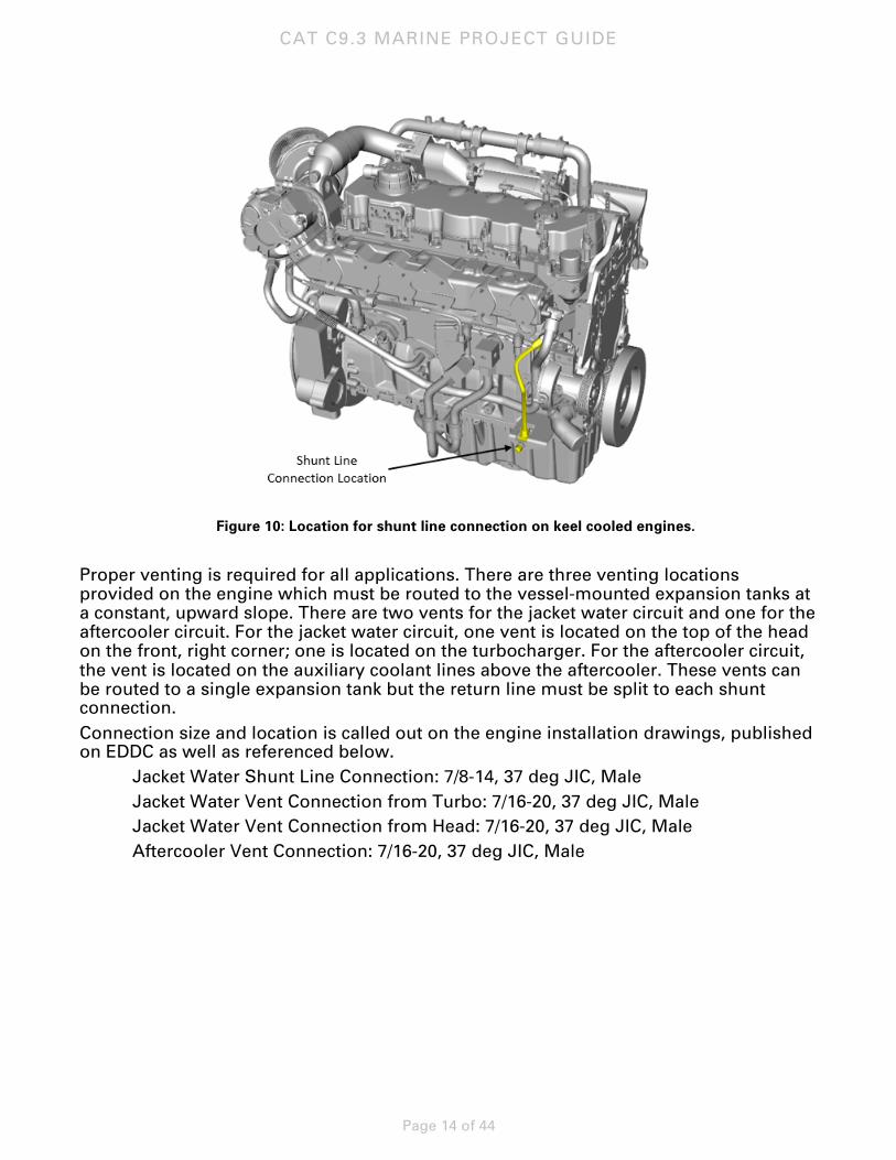
Venting Keel cooled engines are not designed to accommodate the coolant thermal expansion. An external, vessel-mounted expansion tank must connect to the jacket water system shunt line connection provided on the front, right hand side of the engine (viewed from the flywheel) behind the jacket water pump. A shunt connection is not provided on the engine for the aftercooler circuit and this must be routed into the vessel side piping on the inlet to the pump. The vessel expansion tanks must be sized to account for the total system expansion volume (engine, piping, keel coolers, etc.) of each circuit. Note that the volume of the engine must also be taken into account when sizing this expansion tank, as there is no expansion tank included in the engine package to account for this volume. Engine cooling system volumes are available in TMI under the systems data.
Connection size and location is called out on the engine installation drawings, published on EDDC. Refer to the Cooling Systems A&I Guide (LEBW4978) available on Power Net for additional information on sizing and connecting to the expansion tank. The vessel-mounted expansion tanks should NOT be connected in-line with the keel cooler supply and return connections.
CAT C9.3 MARINE PROJECT GUIDE
Page 14 of 44
Figure 10: Location for shunt line connection on keel cooled engines.
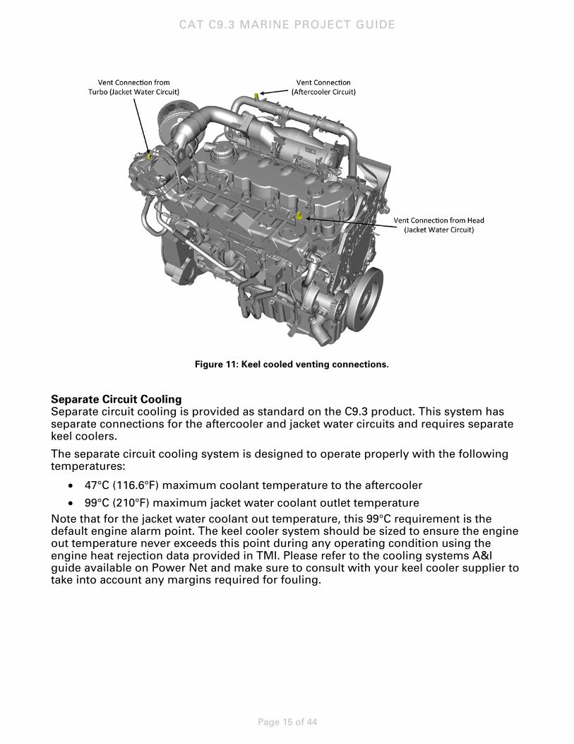
Proper venting is required for all applications. There are three venting locations provided on the engine which must be routed to the vessel-mounted expansion tanks at a constant, upward slope. There are two vents for the jacket water circuit and one for the aftercooler circuit. For the jacket water circuit, one vent is located on the top of the head on the front, right corner; one is located on the turbocharger. For the aftercooler circuit, the vent is located on the auxiliary coolant lines above the aftercooler. These vents can be routed to a single expansion tank but the return line must be split to each shunt connection. Connection size and location is called out on the engine installation drawings, published on EDDC as well as referenced below. Jacket Water Shunt Line Connection: 7/8-14, 37 deg JIC, Male Jacket Water Vent Connection from Turbo: 7/16-20, 37 deg JIC, Male Jacket Water Vent Connection from Head: 7/16-20, 37 deg JIC, Male Aftercooler Vent Connection: 7/16-20, 37 deg JIC, Male
CAT C9.3 MARINE PROJECT GUIDE
Page 15 of 44
Figure 11: Keel cooled venting connections.
Separate Circuit Cooling Separate circuit cooling is provided as standard on the C9.3 product. This system has separate connections for the aftercooler and jacket water circuits and requires separate keel coolers.
The separate circuit cooling system is designed to operate properly with the following temperatures:
• 47°C (116.6°F) maximum coolant temperature to the aftercooler
• 99°C (210°F) maximum jacket water coolant outlet temperature Note that for the jacket water coolant out temperature, this 99°C requirement is the default engine alarm point. The keel cooler system should be sized to ensure the engine out temperature never exceeds this point during any operating condition using the engine heat rejection data provided in TMI. Please refer to the cooling systems A&I guide available on Power Net and make sure to consult with your keel cooler supplier to take into account any margins required for fouling.
CAT C9.3 MARINE PROJECT GUIDE
Page 16 of 44
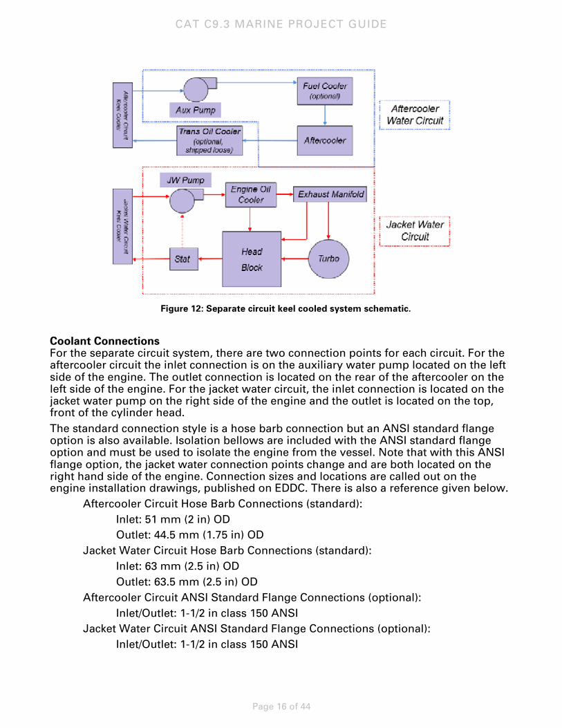
Figure 12: Separate circuit keel cooled system schematic.
Coolant Connections For the separate circuit system, there are two connection points for each circuit. For the aftercooler circuit the inlet connection is on the auxiliary water pump located on the left side of the engine. The outlet connection is located on the rear of the aftercooler on the left side of the engine. For the jacket water circuit, the inlet connection is located on the jacket water pump on the right side of the engine and the outlet is located on the top, front of the cylinder head. The standard connection style is a hose barb connection but an ANSI standard flange option is also available. Isolation bellows are included with the ANSI standard flange option and must be used to isolate the engine from the vessel. Note that with this ANSI flange option, the jacket water connection points change and are both located on the right hand side of the engine. Connection sizes and locations are called out on the engine installation drawings, published on EDDC. There is also a reference given below.
Aftercooler Circuit Hose Barb Connections (standard): Inlet: 51 mm (2 in) OD Outlet: 44.5 mm (1.75 in) OD Jacket Water Circuit Hose Barb Connections (standard): Inlet: 63 mm (2.5 in) OD Outlet: 63.5 mm (2.5 in) OD Aftercooler Circuit ANSI Standard Flange Connections (optional): Inlet/Outlet: 1-1/2 in class 150 ANSI Jacket Water Circuit ANSI Standard Flange Connections (optional): Inlet/Outlet: 1-1/2 in class 150 ANSI
CAT C9.3 MARINE PROJECT GUIDE
Page 17 of 44
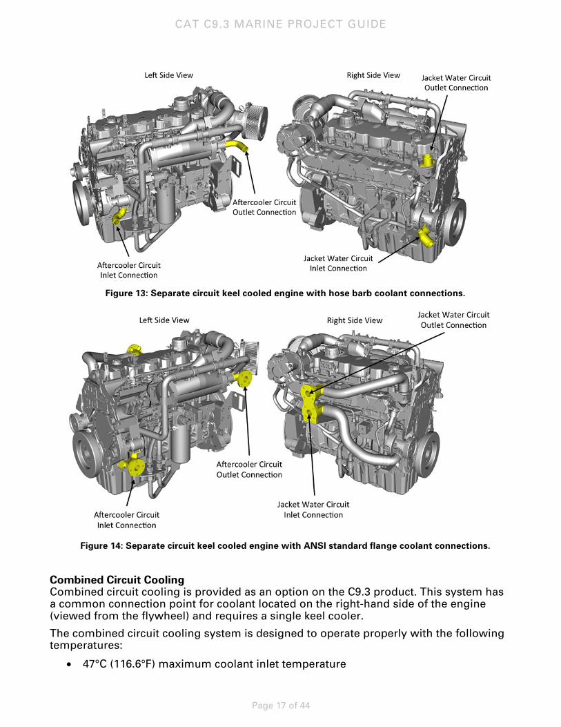
Figure 13: Separate circuit keel cooled engine with hose barb coolant connections.
Figure 14: Separate circuit keel cooled engine with ANSI standard flange coolant connections.
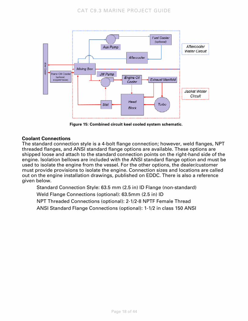
Combined Circuit Cooling Combined circuit cooling is provided as an option on the C9.3 product. This system has a common connection point for coolant located on the right-hand side of the engine (viewed from the flywheel) and requires a single keel cooler.
The combined circuit cooling system is designed to operate properly with the following temperatures:
• 47°C (116.6°F) maximum coolant inlet temperature
CAT C9.3 MARINE PROJECT GUIDE
Page 18 of 44
Figure 15: Combined circuit keel cooled system schematic.
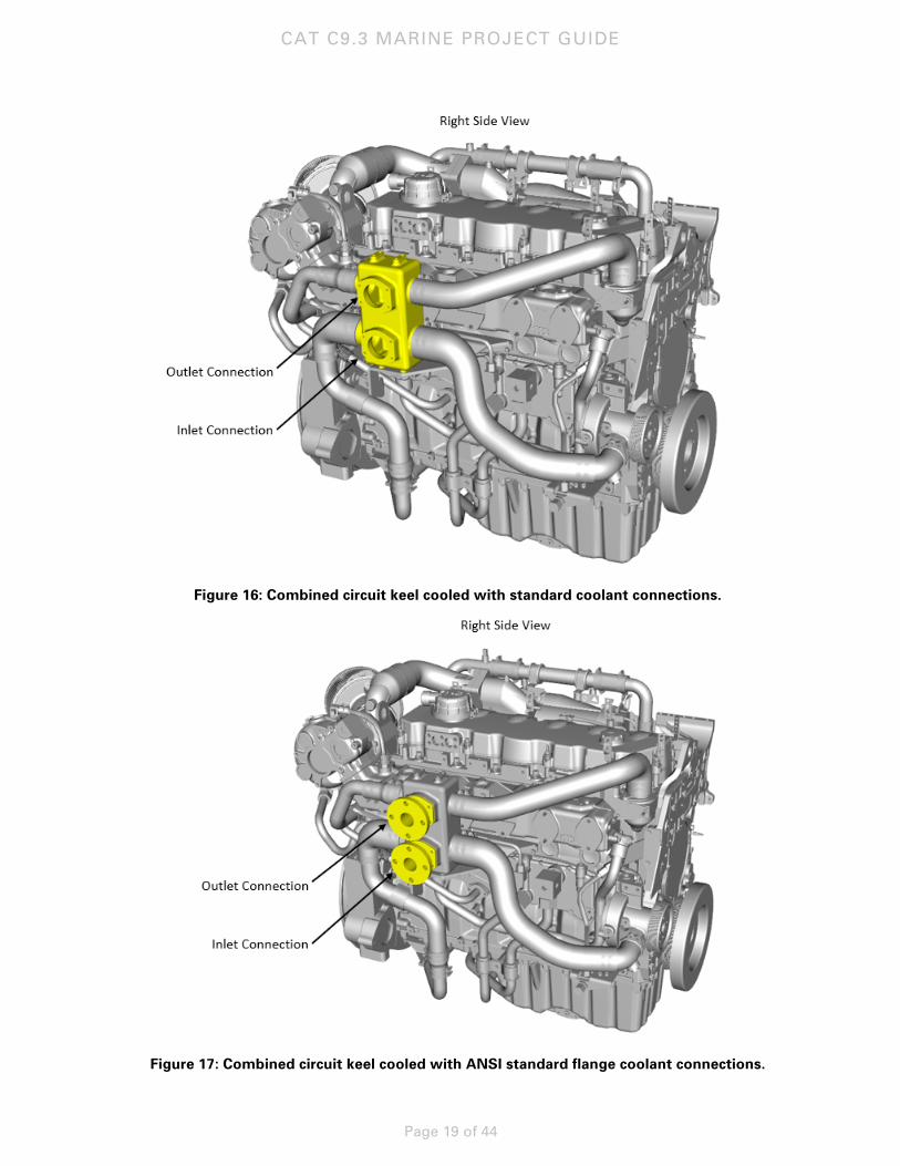
Coolant Connections The standard connection style is a 4-bolt flange connection; however, weld flanges, NPT threaded flanges, and ANSI standard flange options are available. These options are shipped loose and attach to the standard connection points on the right-hand side of the engine. Isolation bellows are included with the ANSI standard flange option and must be used to isolate the engine from the vessel. For the other options, the dealer/customer must provide provisions to isolate the engine. Connection sizes and locations are called out on the engine installation drawings, published on EDDC. There is also a reference given below. Standard Connection Style: 63.5 mm (2.5 in) ID Flange (non-standard) Weld Flange Connections (optional): 63.5mm (2.5 in) ID NPT Threaded Connections (optional): 2-1/2-8 NPTF Female Thread ANSI Standard Flange Connections (optional): 1-1/2 in class 150 ANSI
CAT C9.3 MARINE PROJECT GUIDE
Page 19 of 44
Figure 16: Combined circuit keel cooled with standard coolant connections.
Figure 17: Combined circuit keel cooled with ANSI standard flange coolant connections.
CAT C9.3 MARINE PROJECT GUIDE
Page 20 of 44
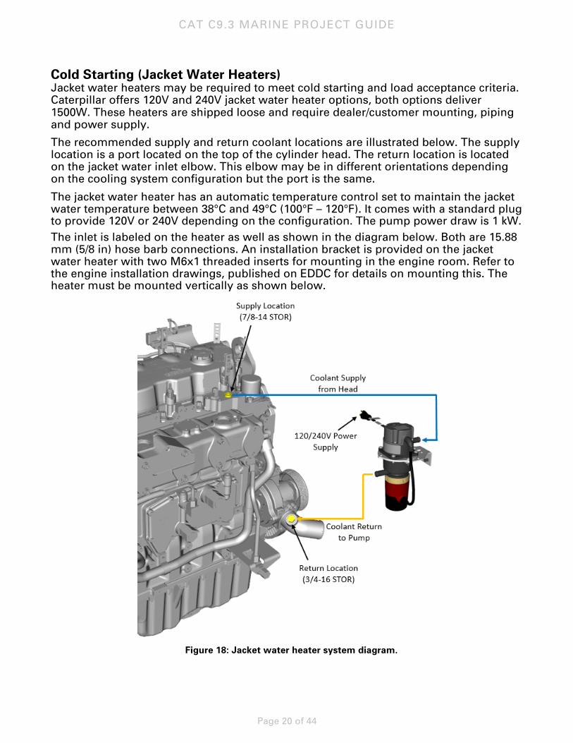
Cold Starting (Jacket Water Heaters) Jacket water heaters may be required to meet cold starting and load acceptance criteria. Caterpillar offers 120V and 240V jacket water heater options, both options deliver 1500W. These heaters are shipped loose and require dealer/customer mounting, piping and power supply.
The recommended supply and return coolant locations are illustrated below. The supply location is a port located on the top of the cylinder head. The return location is located on the jacket water inlet elbow. This elbow may be in different orientations depending on the cooling system configuration but the port is the same.
The jacket water heater has an automatic temperature control set to maintain the jacket water temperature between 38°C and 49°C (100°F – 120°F). It comes with a standard plug to provide 120V or 240V depending on the configuration. The pump power draw is 1 kW. The inlet is labeled on the heater as well as shown in the diagram below. Both are 15.88 mm (5/8 in) hose barb connections. An installation bracket is provided on the jacket water heater with two M6x1 threaded inserts for mounting in the engine room. Refer to the engine installation drawings, published on EDDC for details on mounting this. The heater must be mounted vertically as shown below.
Figure 18: Jacket water heater system diagram.
CAT C9.3 MARINE PROJECT GUIDE
Page 21 of 44
The engine is qualified to cold start down to -10C with no starting aids required. The engine is qualified for cold start down to -20C with only a jacket water heater installed.
Jacket water heaters are generally recommended regardless of starting temperatures to ensure quick starts and reduce the potential for corrosion.
Water Quality, Rust Inhibitors, and Antifreeze Maintaining water quality is very important in closed cooling systems. Excessive hardness will cause deposits, fouling, and reduced effectiveness of cooling system components. Caterpillar has coolant inhibitor available to properly condition the cooling water. When using Cat inhibitor, the cooling water piping must not be a galvanized material, and aluminum should not be used. If the piping is galvanized, the zinc will react with the coolant inhibitor causing material to deposit in the treated water system which may lead to fouling in the treated water circuit.
For the raw water (sea water) system, strainers are recommended to protect downstream components and ensure ideal engine performance. Please refer to the cooling systems A&I guide (LEBW4978) available on PowerNet for information on strainer selection, sizing and installation.
Coolant Heat Recovery Caterpillar does not offer a heat recovery system option. Please refer to the ports provided in the Cold Starting (Jacket Water Heaters) section if your application requires one of these. These are also the recommended ports for a heat recovery system.
If a heat recovery system is required, Caterpillar recommends installing shut-off valves on the supply and return lines from the engine to the system. Be sure to include the coolant volume in the cabin heater loop in the total coolant system volume. Adding coolant to the total system volume will increase required expansion volume. This volume is not accounted for in the expansion volume designed into the heat exchanger cooled engine arrangement.
Commission the engine first without the heat recovery system active to ensure the engine meets application requirements. Once complete operate the engine with the heat recovery system active. To ensure the engine is protected from over-cooling as a result of the heat recovery system being implemented, the measured jacket water temperature should be 70°C (158°F) or above.
Exhaust System The C9.3 engines have a water-cooled exhaust manifold and turbine housing.
Exhaust Backpressure Limits The total exhaust backpressure limit is published in TMI under systems data. This level was established with an emphasis on low specific fuel consumption and exhaust valve temperatures. Therefore, to achieve proper performance of the engine, the exhaust backpressures must be kept below the published limit.
System backpressure should be measured in a straight length of the exhaust pipe at least three to five pipe diameters away from the last size transition from the turbocharger outlet. System backpressure measurement is part of the engine commissioning.
CAT C9.3 MARINE PROJECT GUIDE
Page 22 of 44
Accurately measuring the exhaust pressure is a difficult task. If the probe is not perpendicular to the flow you can get higher or lower values due to a venturi or static pressure affect across the probe. In addition if you just have a pipe probe entering the stream it should be a minimum diameter. Probes larger than 9.5 mm (3/8 in.) diameter can also get a venturi effect and can make the pressures read low.
Refer to LEBW4970 for additional information on measuring exhaust backpressure.
Turbochargers Turbocharger outlet connections and geometry are illustrated on the engine installation drawings available in EDDC. Optional attachments such as flexible fittings (bellows), 90 degree elbows, water-cooled elbows, mufflers and spark arresting mufflers (silencers) can be ordered shipped loose with the engine.
The exhaust bellows are intended to compensate for thermal growth and movement of the engine. The supplied exhaust bellows will only handle the engine movement and thermal growth. In general, the supplied bellows are rated for 10% longitudinal compression or extension. For example, for the 12 inch bellow, allowable compression or elongation is 1.2 inches. The allowable bending of the bellow is roughly 15 degrees.
The vessel exhaust system structure including any elbow or bellows should not be supported by the engine. The weight of these components should be externally supported and not allowed to rest on the turbocharger.
Exhaust Piping A common exhaust system for multiple installations is not acceptable. An exhaust system combined with other engines allows operating engines to force exhaust gases into engines not operating. The water vapor condenses in the cold engines and may cause engine damage. Additionally, soot clogs turbochargers, aftercoolers, and cleaner elements. Valves separating engines’ exhaust systems are also discouraged. High temperatures warp valve seats and soot deposit causes leakage.
The exhaust pipe diameter is based on engine output, gas flow, and length of pipe and number of bends. Sharp bends should be avoided and, where necessary, should have the largest possible radius. The minimum radius should be 1-1/2 pipe diameters. The piping should be as short as possible and insulated. The insulation should be protected by mechanical lagging to keep it intact. All flexible exhaust fittings should be insulated using removable quilted blankets. It is recommended to provide the system with a valve drain arrangement to prevent rainwater from entering the engine during prolonged shutdown periods. For testing purposes, the exhaust system must have a test port installed after the combined turbocharger outlets.
Exhaust piping must be able to expand and contract. It is required that one fixed point be installed directly after the flexible exhaust fitting at the turbocharger outlet. This will prevent the transmission of forces resulting from weight, thermal expansion, or lateral displacement of the external exhaust piping from acting on the turbocharger.
Water-cooled exhaust systems are commonly used in the fast vessel industry. The systems are designed by the yard or consultants and vary somewhat from installation to installation. Caterpillar has no objections to these systems provided that the engine is properly protected and the parameters as outlined are adhered to. This is the shipyard’s responsibility.
CAT C9.3 MARINE PROJECT GUIDE
Page 23 of 44
Fuel System
Introduction The C9.3 engine has a high pressure common rail (HPCR) fuel system. A gear-driven high pressure fuel pump located on the front, left side of the engine provides fuel to the rail located on the left side of the head. Individual fuel lines run from this rail into the head. A low-pressure fuel transfer pump is also integrated into the high pressure common rail pump. Priming pumps are offered as shipped-loose attachments to be installed in between the primary filters and the engine fuel inlet connection. Cleanliness is critical in a HPCR fuel system and the C9.3 engine is equipped with a three-stage fuel filtration system. The second and third stages are installed on the engine while the primary stage is provided on all engines as shipped loose to be mounted in the vessel engine room.
Tank Position The fuel system must assure a continuous, clean supply of fuel. If the main fuel supply is located above the height of the engine fuel injectors, we recommend an auxiliary day tank. In installations where the main fuel tank is above the level of the injectors, auxiliary day tanks are recommended to eliminate the fuel head pressure that would otherwise be placed on the engine fuel system. Auxiliary day tanks are also used if the fuel transfer pump does not have the necessary lift to pump fuel from the main tank. If a higher main tank position is required and installation of an auxiliary day tank is not possible, an open/close solenoid valve may be installed in the fuel supply line and a 3.45 kPa (0.5 psi) check valve may be installed in the fuel return line. Without an auxiliary day tank installed, the low pressure fuel system may still meet each of the external restriction specifications; however, a solenoid valve is still recommended to allow fuel to be shut off to the engine if needed. This solenoid valve should be open with keyswitch “on” and closed with keyswitch “off.” Solenoid or shut-off valves should not be used in fuel return lines. Engine operation with the valve closed will cause damaging pressures. The maximum static fuel inlet pressure at the transfer pump is 70 kPa.
Refer to LEDM0106-02 for further information on fuel tank position.
Line Restriction The internal diameter of the piping/line size supplying fuel to the engine and the fuel return line to the tank should be equal to or greater than the line size at the engine connections.
Maximum inlet restriction before the transfer pump and outlet restriction from the engine are published in systems data in TMI. The restriction of the priming pump and primary fuel filters must be taken into account in this total inlet restriction. The restriction of the Caterpillar supplied priming pumps is 5 kPa and the restriction of the primary filter base with clean filter(s) is 10 kPa.
Ensure all air is removed from the fuel system prior to starting the engine. Air in the system causes hard starting and erratic engine operation, and can erode injectors. The priming pump should be used after changing filters to ensure air is not trapped in the system.
CAT C9.3 MARINE PROJECT GUIDE
Page 24 of 44
Fuel Cooler The fuel cooler is optional on all engines. The fuel cooler is a tube-type brazed cooler in the aftercooler circuit. The cooler is located on the left-hand side of the engine above the aftercooler.
The maximum fuel temperature into the fuel transfer pump is 79°C. The fuel temp rise across the engine depends on engine rating and load but is roughly 30°C (86°F). The heat rejected to the fuel also depends on rating and load but is roughly 6 kW (342 BTU/min).
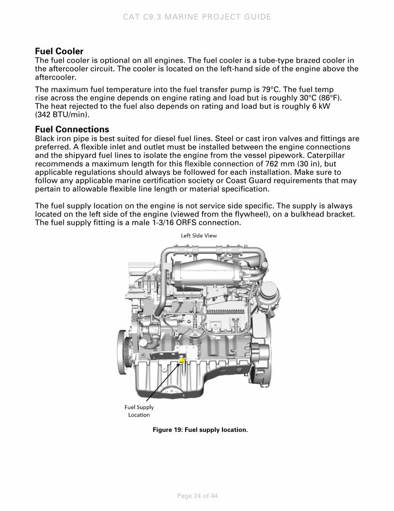
Fuel Connections Black iron pipe is best suited for diesel fuel lines. Steel or cast iron valves and fittings are preferred. A flexible inlet and outlet must be installed between the engine connections and the shipyard fuel lines to isolate the engine from the vessel pipework. Caterpillar recommends a maximum length for this flexible connection of 762 mm (30 in), but applicable regulations should always be followed for each installation. Make sure to follow any applicable marine certification society or Coast Guard requirements that may pertain to allowable flexible line length or material specification. The fuel supply location on the engine is not service side specific. The supply is always located on the left side of the engine (viewed from the flywheel), on a bulkhead bracket. The fuel supply fitting is a male 1-3/16 ORFS connection.
Figure 19: Fuel supply location.
CAT C9.3 MARINE PROJECT GUIDE
Page 25 of 44
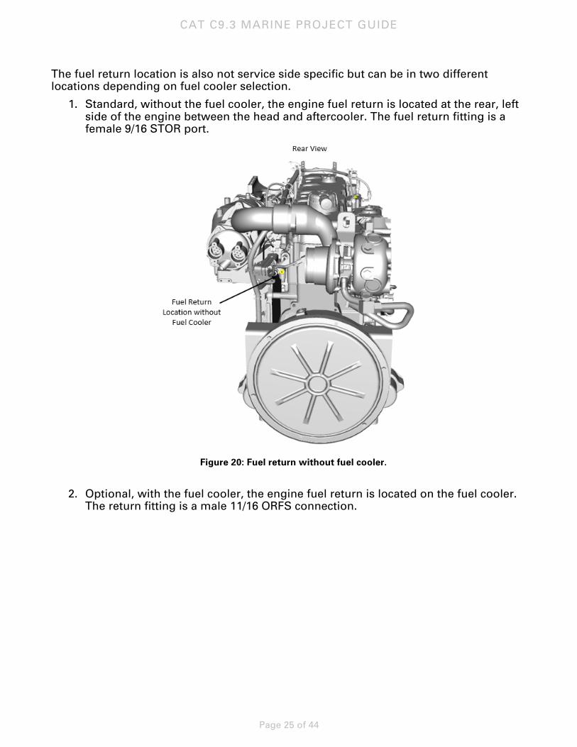
The fuel return location is also not service side specific but can be in two different locations depending on fuel cooler selection.
1. Standard, without the fuel cooler, the engine fuel return is located at the rear, left side of the engine between the head and aftercooler. The fuel return fitting is a female 9/16 STOR port.
Figure 20: Fuel return without fuel cooler.
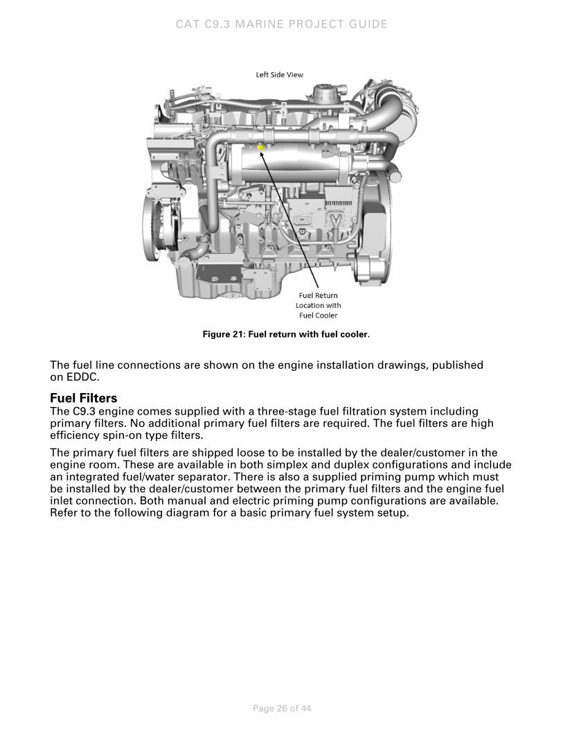
2. Optional, with the fuel cooler, the engine fuel return is located on the fuel cooler.
The return fitting is a male 11/16 ORFS connection.
CAT C9.3 MARINE PROJECT GUIDE
Page 26 of 44
Figure 21: Fuel return with fuel cooler.
The fuel line connections are shown on the engine installation drawings, published on EDDC.
Fuel Filters The C9.3 engine comes supplied with a three-stage fuel filtration system including primary filters. No additional primary fuel filters are required. The fuel filters are high efficiency spin-on type filters.
The primary fuel filters are shipped loose to be installed by the dealer/customer in the engine room. These are available in both simplex and duplex configurations and include an integrated fuel/water separator. There is also a supplied priming pump which must be installed by the dealer/customer between the primary fuel filters and the engine fuel inlet connection. Both manual and electric priming pump configurations are available. Refer to the following diagram for a basic primary fuel system setup.
CAT C9.3 MARINE PROJECT GUIDE
Page 27 of 44
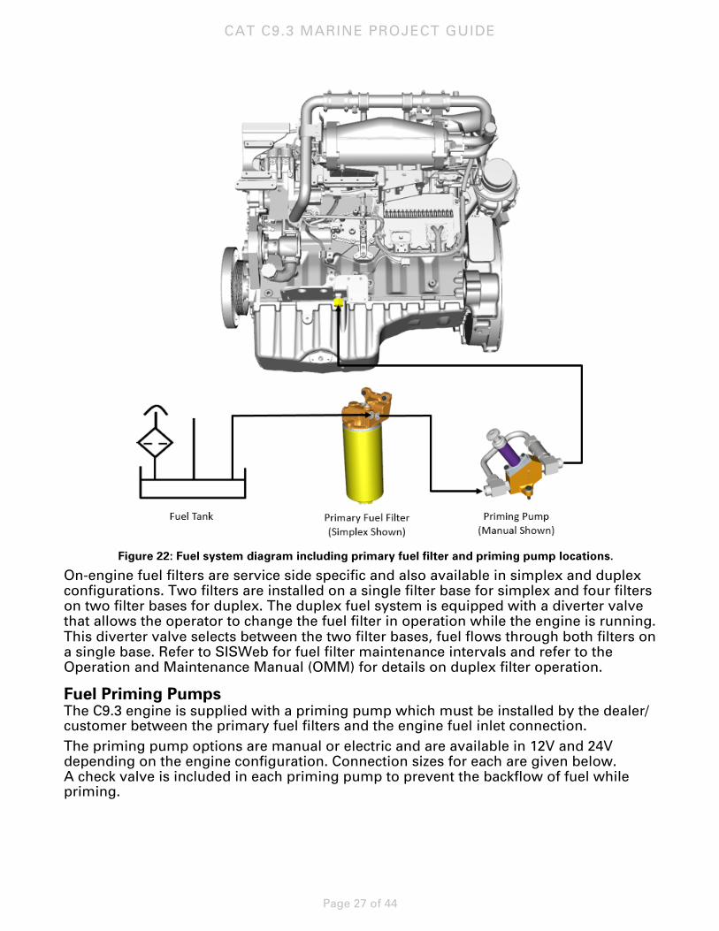
Figure 22: Fuel system diagram including primary fuel filter and priming pump locations.
On-engine fuel filters are service side specific and also available in simplex and duplex configurations. Two filters are installed on a single filter base for simplex and four filters on two filter bases for duplex. The duplex fuel system is equipped with a diverter valve that allows the operator to change the fuel filter in operation while the engine is running. This diverter valve selects between the two filter bases, fuel flows through both filters on a single base. Refer to SISWeb for fuel filter maintenance intervals and refer to the Operation and Maintenance Manual (OMM) for details on duplex filter operation.
Fuel Priming Pumps The C9.3 engine is supplied with a priming pump which must be installed by the dealer/ customer between the primary fuel filters and the engine fuel inlet connection. The priming pump options are manual or electric and are available in 12V and 24V depending on the engine configuration. Connection sizes for each are given below. A check valve is included in each priming pump to prevent the backflow of fuel while priming.
CAT C9.3 MARINE PROJECT GUIDE
Page 28 of 44
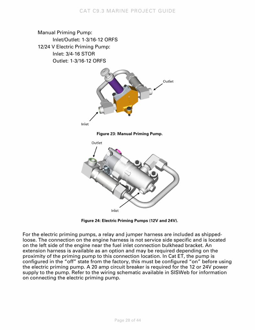
Manual Priming Pump: Inlet/Outlet: 1-3/16-12 ORFS 12/24 V Electric Priming Pump: Inlet: 3/4-16 STOR Outlet: 1-3/16-12 ORFS
Figure 23: Manual Priming Pump.
Figure 24: Electric Priming Pumps (12V and 24V).
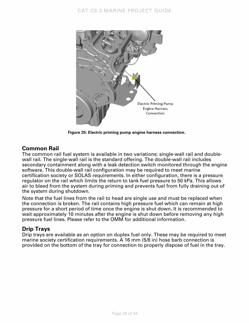
For the electric priming pumps, a relay and jumper harness are included as shipped-loose. The connection on the engine harness is not service side specific and is located on the left side of the engine near the fuel inlet connection bulkhead bracket. An extension harness is available as an option and may be required depending on the proximity of the priming pump to this connection location. In Cat ET, the pump is configured in the “off” state from the factory, this must be configured “on” before using the electric priming pump. A 20 amp circuit breaker is required for the 12 or 24V power supply to the pump. Refer to the wiring schematic available in SISWeb for information on connecting the electric priming pump.
CAT C9.3 MARINE PROJECT GUIDE
Page 29 of 44
Figure 25: Electric priming pump engine harness connection.
Common Rail The common rail fuel system is available in two variations: single-wall rail and double-wall rail. The single-wall rail is the standard offering. The double-wall rail includes secondary containment along with a leak detection switch monitored through the engine software. This double-wall rail configuration may be required to meet marine certification society or SOLAS requirements. In either configuration, there is a pressure regulator on the rail which limits the return to tank fuel pressure to 50 kPa. This allows air to bleed from the system during priming and prevents fuel from fully draining out of the system during shutdown. Note that the fuel lines from the rail to head are single use and must be replaced when the connection is broken. The rail contains high pressure fuel which can remain at high pressure for a short period of time once the engine is shut down. It is recommended to wait approximately 10 minutes after the engine is shut down before removing any high pressure fuel lines. Please refer to the OMM for additional information.
Drip Trays Drip trays are available as an option on duplex fuel only. These may be required to meet marine society certification requirements. A 16 mm (5/8 in) hose barb connection is provided on the bottom of the tray for connection to properly dispose of fuel in the tray.
CAT C9.3 MARINE PROJECT GUIDE
Page 30 of 44
Lubrication Oil System
General The C9.3 engine offers simplex or duplex oil filtration system. The simplex filter is installed on the engine service side and the optional duplex system has a shipped loose duplex filter base which must be installed by the dealer/customer in the engine room. Each engine is equipped with a plate type oil cooler integrated into the right-hand side of the block. The oil is cooled by treated water from the jacket water circuit.
Oil Pan All ratings have a single oil pan offering with a deep, front biased sump. The C9.3 oil pan is rated for 45 degree static inclination in all directions. When equipped with the installed air cleaner with closed crankcase ventilation, this system has a more restrictive static inclination capability of 18 degrees rearward tilt and 35 degree side-to-side.
The C9.3 engine is equipped with a marked dipstick. This dipstick is calibrated for a level installation. Due to the potential remote oil filter lines adding an undefined volume of oil on initial fill, it is recommended to refer to this dipstick. In the event of a significant rearward installation angle, alternate dipstick markings may need to be made.
Refer to SISWeb for oil maintenance intervals.
Oil Filters The lubrication oil filters are high efficiency spin-on type filters. The simplex oil filter system is provided as standard engine equipment installed on the engine service side.
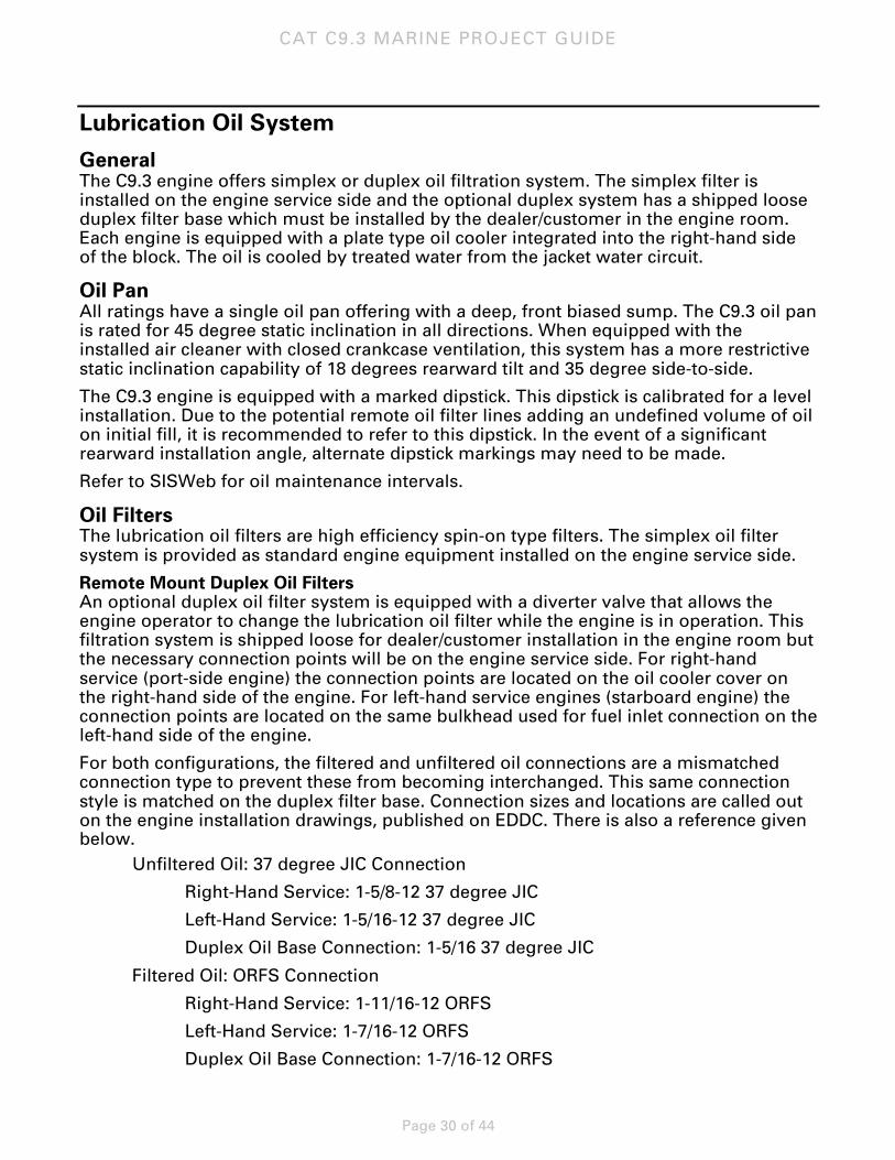
Remote Mount Duplex Oil Filters An optional duplex oil filter system is equipped with a diverter valve that allows the engine operator to change the lubrication oil filter while the engine is in operation. This filtration system is shipped loose for dealer/customer installation in the engine room but the necessary connection points will be on the engine service side. For right-hand service (port-side engine) the connection points are located on the oil cooler cover on the right-hand side of the engine. For left-hand service engines (starboard engine) the connection points are located on the same bulkhead used for fuel inlet connection on the left-hand side of the engine.
For both configurations, the filtered and unfiltered oil connections are a mismatched connection type to prevent these from becoming interchanged. This same connection style is matched on the duplex filter base. Connection sizes and locations are called out on the engine installation drawings, published on EDDC. There is also a reference given below. Unfiltered Oil: 37 degree JIC Connection
Right-Hand Service: 1-5/8-12 37 degree JIC
Left-Hand Service: 1-5/16-12 37 degree JIC
Duplex Oil Base Connection: 1-5/16 37 degree JIC
Filtered Oil: ORFS Connection
Right-Hand Service: 1-11/16-12 ORFS
Left-Hand Service: 1-7/16-12 ORFS
Duplex Oil Base Connection: 1-7/16-12 ORFS
CAT C9.3 MARINE PROJECT GUIDE
Page 31 of 44
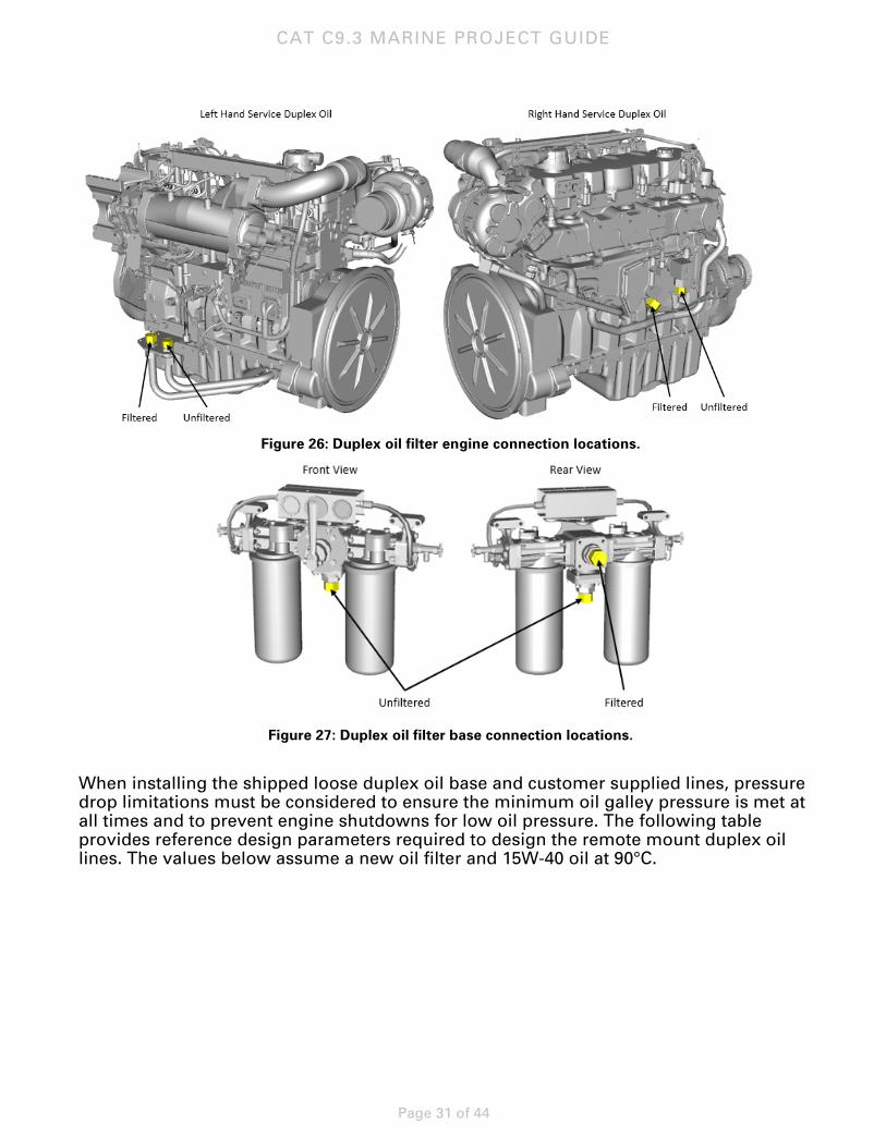
Figure 26: Duplex oil filter engine connection locations.
Figure 27: Duplex oil filter base connection locations.
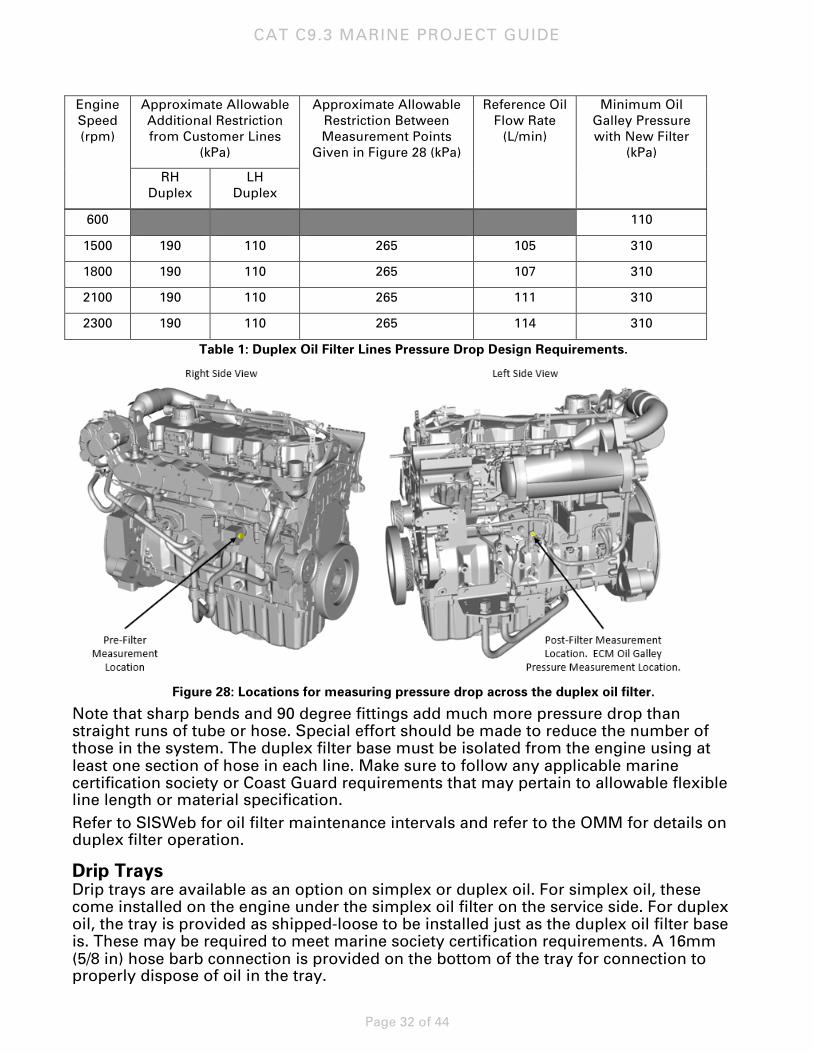
When installing the shipped loose duplex oil base and customer supplied lines, pressure drop limitations must be considered to ensure the minimum oil galley pressure is met at all times and to prevent engine shutdowns for low oil pressure. The following table provides reference design parameters required to design the remote mount duplex oil lines. The values below assume a new oil filter and 15W-40 oil at 90°C.
CAT C9.3 MARINE PROJECT GUIDE
Page 32 of 44
Engine Speed (rpm)
Approximate Allowable Additional Restriction from Customer Lines
(kPa)
Approximate Allowable Restriction Between Measurement Points
Given in Figure 28 (kPa)
Reference Oil Flow Rate
(L/min)
Minimum Oil Galley Pressure with New Filter
(kPa)
RH Duplex
LH Duplex
600 110
1500 190 110 265 105 310
1800 190 110 265 107 310
2100 190 110 265 111 310
2300 190 110 265 114 310
Table 1: Duplex Oil Filter Lines Pressure Drop Design Requirements.
Figure 28: Locations for measuring pressure drop across the duplex oil filter.
Note that sharp bends and 90 degree fittings add much more pressure drop than straight runs of tube or hose. Special effort should be made to reduce the number of those in the system. The duplex filter base must be isolated from the engine using at least one section of hose in each line. Make sure to follow any applicable marine certification society or Coast Guard requirements that may pertain to allowable flexible line length or material specification. Refer to SISWeb for oil filter maintenance intervals and refer to the OMM for details on duplex filter operation.
Drip Trays Drip trays are available as an option on simplex or duplex oil. For simplex oil, these come installed on the engine under the simplex oil filter on the service side. For duplex oil, the tray is provided as shipped-loose to be installed just as the duplex oil filter base is. These may be required to meet marine society certification requirements. A 16mm (5/8 in) hose barb connection is provided on the bottom of the tray for connection to properly dispose of oil in the tray.
CAT C9.3 MARINE PROJECT GUIDE
Page 33 of 44
Transmission Oil Cooler A transmission oil cooler is offered as an option for propulsion engines. For heat exchanger cooling, this is installed on the right-hand side of the engine under the heat exchanger. For keel-cooled engines, this is shipped loose to be installed in the vessel side piping. Refer to the cooling system diagrams in the keel-cooled engines section of this document for a reference on where in the system this should be installed.
Power Take Offs The standard C9.3 engine has no provisions from front end attachments. However a stub shaft and V-belt drive are available as options. A special front belt guard is installed on engines equipped with a front end attachment. This guard allows access to the stub shaft or pulley. The customer/dealer is responsible for installing additional guarding as necessary to meet applicable regulations.
Front Stub Shaft The front stub shaft is installed on the front of the vibration damper. The stub shaft is 69.8 mm (2.75 in) in diameter and has a 19.038 mm (0.75 in) wide key slot. A 19.06 mm (0.75 in) wide key is included as shipped-loose. Additional details are available in the installation drawings on EDDC. The maximum torque capability of the stub shaft is 955 N•m (704 lb-ft).
Belt Drive A three-groove pulley is offered installed on the front of the vibration damper. This pulley is for an SAE 15A belt. Refer to component data in TMI for allowable side loads.
Starting System The C9.3 engine is available with the starter configurations given below:
• No Starter • 24V Electric Starter (left-side flywheel pocket) • 12V Electric Starter (left-side flywheel pocket) • Air Starter (right-side flywheel pocket) • Dual Starters: 24V Electric Starter (left-side flywheel pocket) and Air Starter (right-
side flywheel pocket) • Dual Starters: 24V Electric Starters (both flywheel pockets)
Electric Starter Electric starters are available in either a 12V or 24V configuration. The electric starter always installed in the left pocket of the flywheel housing.

CAT C9.3 MARINE PROJECT GUIDE
Page 34 of 44
Air Starter This air starter is a vane-type starter motor that does not require fuel or oil lubrication. The air starter is always installed in the right-side flywheel pocket. The air starter is only available on 24V engine configurations.
The air supply connection is on the rear, right-hand side of the engine. The connection size is 1-11 1/2 NPT.
Air Pressure, Quality, and Filtration The air starter requires 620 – 827 kPa (90 – 120 psi) air supply pressure. Upstream installation and use of a filter or Y-strainer is recommended to protect the air starter from contaminants. Before running the starter, purge the upstream air system to remove debris. Inspect the condition of the filter on a monthly basis or as needed based on air quality and/or environment. Clean or replace filter as needed to prevent flow restrictions, reduced air starter power output, and contamination of starter controls. A filter is required when air quality does not meet 400-micron requirement.
Both a pressure regulator and a strainer that meet the above requirements are included as shipped-loose when the engine is equipped with an air starter.
A silencer is not available, the noise level of the starter is 113 dB.
Lubrication The air starter does not require lubrication supply. Therefore, the starter exhaust does not produce an oil or diesel mist, yet may contain condensed air system moisture and/or site air system chemicals/additives. The starter’s internal gearbox and bearings are grease-packed and sealed.
Emergency Starting The solenoid valve on the assembly has a manual bypass button. This allows the starter to be operated manually (without electrical power/control voltage). Continuous manual (pneumatic) control of the starter could potentially result in improper starter engagement. To minimize risk, it is strongly recommended for this feature to be used only in emergencies. DO NOT routinely use the manual bypass to operate the starter.
If the starter will only operate using the manual bypass, this likely indicates a problem originating with the following:
• Pilot air solenoid
• Electronic controller
• Communication with the ECM
Emergency Starting Procedure: 1. Locate the starter’s pilot air solenoid. 2. Locate the button on solenoid valve.
Using a pointed object (pen, paper clip, screw driver), depress the button to actuate the starter.
CAUTION: The starter must never be engaged on a running engine. In the event of emergencies (or loss of control voltage), use the manual bypass feature on the control solenoid to manually start the engine.
DO NOT repeatedly use the manual bypass to defeat the air starter’s control module and engine control module. Make necessary repairs as soon as possible to avoid repeated use of the bypass feature, as this may result in air starter or engine damage. The starter should never be used to “bump” or “bar” the engine.
CAT C9.3 MARINE PROJECT GUIDE
Page 35 of 44
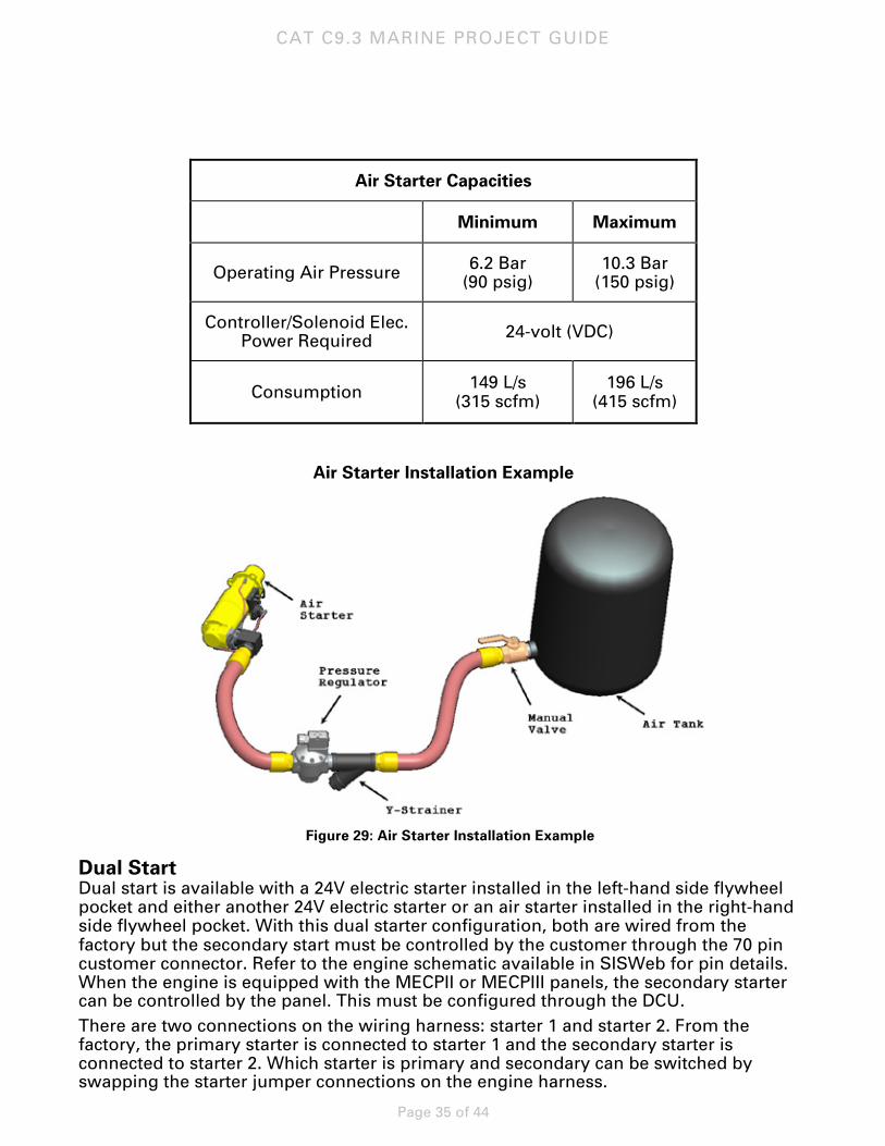
Air Starter Capacities
Minimum Maximum
Operating Air Pressure 6.2 Bar (90 psig)
10.3 Bar (150 psig)
Controller/Solenoid Elec. Power Required 24-volt (VDC)
Consumption 149 L/s (315 scfm)
196 L/s (415 scfm)
Air Starter Installation Example
Figure 29: Air Starter Installation Example
Dual Start Dual start is available with a 24V electric starter installed in the left-hand side flywheel pocket and either another 24V electric starter or an air starter installed in the right-hand side flywheel pocket. With this dual starter configuration, both are wired from the factory but the secondary start must be controlled by the customer through the 70 pin customer connector. Refer to the engine schematic available in SISWeb for pin details. When the engine is equipped with the MECPII or MECPIII panels, the secondary starter can be controlled by the panel. This must be configured through the DCU. There are two connections on the wiring harness: starter 1 and starter 2. From the factory, the primary starter is connected to starter 1 and the secondary starter is connected to starter 2. Which starter is primary and secondary can be switched by swapping the starter jumper connections on the engine harness.
CAT C9.3 MARINE PROJECT GUIDE
Page 36 of 44
Charging System The C9.3 engine is available with the charging system configurations given below:
• No Alternator • 24V, 70 Amp Alternator • 24V, 105 Amp Alternator • 12V, 110 Amp Alternator • Mounting for customer supplied alternator
All alternators are pad mounted on the front, left side of the engine. These are brushless with insulated ground. If the engine is equipped with both an alternator and electric starter, alternator to starter cables will be installed from the factory. If an electric starter is not equipped, any necessary cables need to be supplied by the customer/dealer. The customer-supplied alternator mounting pad option provides a mounting pad on the front, left of the engine. The engine is shipped with idlers and tensioners installed but an alternator belt shipped loose. The engine is equipped with a damper guard compatible with an alternator. Refer to installation drawings available in EDDC for dimensions of the mounting pad. The belt supplied is a 12-rib poly-v. Any necessary starter-to-alternator cables need to be supplied by the customer/dealer.
Mounting System
Isolator Mounts Caterpillar offers a thrust capable mount recommended in applications that transmit thrust into the mounting system, for example, close-coupled engine and gearbox (transmission) applications. In this circumstance the mounting system for the engine and gearbox is subject to thrust load being transmitted through the driveline. The durometer for the thrust mount is 75.
Electronic System The C9.3 engine is an electronically controlled engine with an ADEM™ 4 Electronic Control Module (ECM).
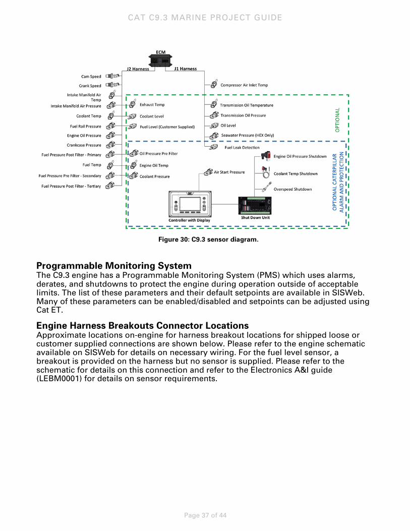
Sensor Architecture The following diagram shows the C9.3 standard and optional sensor system architecture.
CAT C9.3 MARINE PROJECT GUIDE
Page 37 of 44
Figure 30: C9.3 sensor diagram.
Programmable Monitoring System The C9.3 engine has a Programmable Monitoring System (PMS) which uses alarms, derates, and shutdowns to protect the engine during operation outside of acceptable limits. The list of these parameters and their default setpoints are available in SISWeb. Many of these parameters can be enabled/disabled and setpoints can be adjusted using Cat ET.
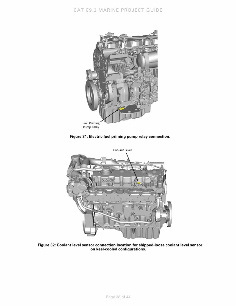
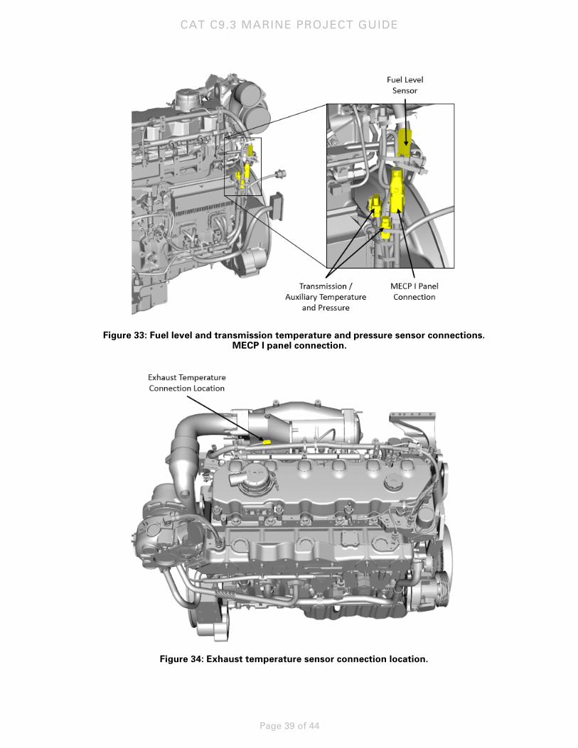
Engine Harness Breakouts Connector Locations Approximate locations on-engine for harness breakout locations for shipped loose or customer supplied connections are shown below. Please refer to the engine schematic available on SISWeb for details on necessary wiring. For the fuel level sensor, a breakout is provided on the harness but no sensor is supplied. Please refer to the schematic for details on this connection and refer to the Electronics A&I guide (LEBM0001) for details on sensor requirements.
CAT C9.3 MARINE PROJECT GUIDE
Page 38 of 44
Figure 31: Electric fuel priming pump relay connection.
Figure 32: Coolant level sensor connection location for shipped-loose coolant level sensor
on keel-cooled configurations.
CAT C9.3 MARINE PROJECT GUIDE
Page 39 of 44
Figure 33: Fuel level and transmission temperature and pressure sensor connections.
MECP I panel connection.
Figure 34: Exhaust temperature sensor connection location.

CAT C9.3 MARINE PROJECT GUIDE
Page 40 of 44
Customer Connection and J1939 The electrical customer connection on the C9.3 is via 70-pin connector located on the left, rear of the engine. This is referred to as the J3 connector. Refer to the A&I Electronics guide (LEBM0001) and the engine schematic for pin-outs on this connection. Also located in the same left, rear of the engine is a 9-pin, circular connector for the service tool. The optional Caterpillar alarm and protection system comes equipped with an additional 40-pin connector located to the left of the 70-pin J3 connector. This connects between the alarm and protection panel, which is supplied shipped-loose, and the on-engine sensors.
Figure 35: 70-Pin Customer Connector and Service Tool Connector Locations.
Figure 36: 40-Pin Customer Connector and Service Tool Connector Locations.
Refer to the A&I Electronics guide (LEBM0001) for a list of parameters which are broadcast over the J1939 CAN bus.

CAT C9.3 MARINE PROJECT GUIDE
Page 41 of 44
Panels For the C9.3 propulsion engines, the full line of Marine Engine Control Panels (MECP) are available as shipped loose attachments. The MECP I panel is a basic start/stop panel which is not MCS approvable. For MCS approved panels, the MECP II and MECP III panels are offered. These come complete with the Caterpillar alarm and protection system. Refer to LEDM0097 for a full list of features. For the C9.3 auxiliary engines, the Marine Genset Control Panels (MGCP II and MGCP III) are offered. These contain the proper throttle control for a constant speed engine. Both of these panels are MCS approved and come complete with the Caterpillar alarm and protection system. The MECP I panel is offered on the auxiliary engines as well for a non-MCS approvable basic start/stop panel.
Displays The C9.3 propulsion and auxiliary engines also offer a full line of displays which are connected on J1939 via the 70-pin J3 connector including:
• Marine Power Display (MPD) • Color Marine Power Display (CMPD) • 7” Caterpillar Marine Display • 13” Caterpillar Marine Display
For a list of features and a comparison between the MPD and CMPD panels, refer to LEDM8836. For a list of features on the 7” and 13” Caterpillar Marine Displays, refer to LEDM0083.
Hardware Summary
Application Emissions Certification
Emissions Cycle Power Rating Rated Speed (rpm)
S/N Prefix
Engine Sales Model
Hardware
Turbo Piston
Prop (B-Tier) IMO II EPA T3
280 bkW (375 bhp) 1800
CP9 C9.3MP3G
T1 P1
Prop (C-Tier) E3 310 bkW (416 bhp) 2100 T2 P2
Prop (D-Tier) 355 bkW (476 bhp) 2300 T3
Variable Speed Aux
IMO II EPA T3 C1 280 bkW (375 bhp) 1800 T1 P1
Aux / Genset IMO II E2
D2
218 bkW (292 bhp) 1500
CA9 CG9 C9.3MGE3G
T1 P1 Aux / Genset 270 bkW (362 bkW) 1500
Aux / Genset IMO II EPA T3
E2 D2
275 bkW (369 bhp) 1800
Aux / Genset 325 bkW (383 bkW) 1800 T4 P2
Engine Preservation and Packaging The Caterpillar factory has several standard levels of engine preservation and shipment protection. All engines that ship from the factory have plastic wrap protection. The plastic wrap provides approximately 6 to 12 months of external protection from moisture, sun and wind under storage conditions. If the engine is to be stored for longer periods of time, consider specifying storage preservation as described below.
CAT C9.3 MARINE PROJECT GUIDE
Page 42 of 44
Storage preservation protects the engine and accessories from functional deterioration for a minimum of one year. It includes standard protective measures plus vapor corrosion inhibitor (VCI) in all internal compartments and glycol solution in the cooling system.
Export boxing protects the engine and accessories from functional deterioration for a minimum of one year under outside storage conditions. Including standard protective measures, vapor corrosion inhibitor in all internal compartments. The exterior box provides protection against mechanical damage during shipment and storage. All marine engines are placed upon wooden skids prior to shipment. All ship-loose parts are painted and oiled and placed in ship-loose boxes. On arrival, open all boxes and review their contents against the packing list. The parts should then be repackaged and preserved for protection.
Shipbuilder’s Responsibility Unless otherwise specified, the engine buyer shall be responsible for the following:
• Ensure all coolant, lube oil piping, fuel oil piping, exhaust piping, and intake air ducting are free of rust, scale, weld spatter, and foreign material prior to startup of the engines.
• Provide electrical wiring and the necessary piping to the engine, i.e., exhaust piping, fuel oil piping to and from the engine, air piping to the starting motor(s), air filter ducting/piping, crankcase fumes disposal ducting, etc. All of the above noted interconnections need to be designed in such a way so as to comply with acceptable vibratory levels of excitation throughout the entire range of engine operation. No primary resonances in the interface hardware are acceptable.
• Furnish and install standby pumps as required by marine classification societies.
• Install adequate engine foundation and provide proper chocking and alignment between the engine and marine gear.
• Provide adequate clearance for disassembly of engine [overhead clearance for connecting rods and piston removal can be found in the Serviceability Considerations Application and Installation (A&I) Guide LEGM4735 available on Electronic Media Center (EMC)].
• Provide all labor, equipment, and hardware to install the equipment.
• Furnish accurate data for a torsional vibration analysis.
• Provide all coolants, water treatment chemicals (if used), lubricating oil, and fuel oils necessary to operate the engine.
• Warehouse and protect engines, accessories, and miscellaneous ship-loose equipment until their installation. Cat engines are protected against corrosion for inside dry storage for a period up to six months. Provisions for additional storage periods are available from the factory.
CAT C9.3 MARINE PROJECT GUIDE
Page 43 of 44
Reference Material The following information is provided as additional reference to subjects discussed in this guide available on EMC.
LEBM0001 - Marine Engine Electronics C7-C32 Application & Installation Guide LEBW4978 - Cooling Systems – Application & Installation Guide LEDM0083 - Cat Marine Display Customer Flyer LEDM0097 – Propulsion Panel Solutions LEDM0106-00 – Marine Engine Bonding LEDM0106-02 – Low Pressure Fuel Systems LEDM8836 – Cat Marine Power Display Comparison LEGM4735 – Serviceability Considerations, Marine A&I Guide
The product price list can be accessed online through Power Net. https://engines.cat.com/marine
Marine Product Application and Installation webpage can also be accessed via Power Net.
https://engines.cat.com/marine/application
Engine Installation drawings can be retrieved from the EDDC. A paid subscription is required to download drawings from this site.
https://enginedrawings.cat.com/
Technical Marketing Information (TMI)/engine performance data can be obtained from TMI Web.
https://tmiweb.cat.com/
Service and maintenance information can be obtained from the Service Information System (SISWeb)
https://sis.cat.com/
Reference publications can be obtained from EMC https://emc.cat.com/QuickSearch.aspx
CAT C9.3 MARINE PROJECT GUIDE
Page 44 of 44
CAT, CATERPILLAR, BUILT FOR IT, their respective logos, "Caterpillar Yellow", the "Power Edge" trade dress as well as corporate and product identity used herein, are trademarks of Caterpillar and may not be used without permission.
LEBM0048-00 ©2015 Caterpillar All rights reserved.