ca-c combustion analyzers · calculation of combustion air requirement ... model ca-6203 performs a...
TRANSCRIPT

Combust ion Ana lys is
CA-CALC™ Combustion Analyzers
Model 6203 Series
Operation and Service Manual
P/N 1980472 Revision C August 2010
ENERGY AND COMFORT


3
Copyright © TSI Incorporated / 2002–2010 / All rights reserved.
Address TSI Incorporated / 500 Cardigan Road / Shoreview, MN 55126 / USA
Fax No. (651) 490-3824 LIMITATION OF WARRANTY AND LIABILITY (effective July 2000) Seller warrants the goods sold hereunder, under normal use and service as described in the operator's manual, shall be free from defects in workmanship and material for twenty-four (24) months, or the length of time specified in the operator's manual, from the date of shipment to the customer. This warranty period is inclusive of any statutory warranty. This limited warranty is subject to the following exclusions: a. Batteries are warranted for 90 days from the date of shipment to the customer.
Electrochemical gas sensors are warranted for a period of twelve (12) months from the date of shipment to the customer.
b. Parts repaired or replaced as a result of repair services are warranted to be free from defects in workmanship and material, under normal use, for 90 days from the date of shipment.
c. Seller does not provide any warranty on finished goods manufactured by others or on any fuses, batteries or other consumable materials. Only the original manufacturer's warranty applies.
d. Unless specifically authorized in a separate writing by Seller, Seller makes no warranty with respect to, and shall have no liability in connection with, goods which are incorporated into other products or equipment, or which are modified by any person other than Seller.
The foregoing is IN LIEU OF all other warranties and is subject to the LIMITATIONS stated herein. NO OTHER EXPRESS OR IMPLIED WARRANTY OF FITNESS FOR PARTICULAR PURPOSE OR MERCHANTABILITY IS MADE. TO THE EXTENT PERMITTED BY LAW, THE EXCLUSIVE REMEDY OF THE USER OR BUYER, AND THE LIMIT OF SELLER'S LIABILITY FOR ANY AND ALL LOSSES, INJURIES, OR DAMAGES CONCERNING THE GOODS (INCLUDING CLAIMS BASED ON CONTRACT, NEGLIGENCE, TORT, STRICT LIABILITY OR OTHERWISE) SHALL BE THE RETURN OF GOODS TO SELLER AND THE REFUND OF THE PURCHASE PRICE, OR, AT THE OPTION OF SELLER, THE REPAIR OR REPLACEMENT OF THE GOODS. IN NO EVENT SHALL SELLER BE LIABLE FOR ANY SPECIAL, CONSEQUENTIAL OR INCIDENTAL DAMAGES. SELLER SHALL NOT BE RESPONSIBLE FOR INSTALLATION, DISMANTLING OR REINSTALLATION COSTS OR CHARGES. No Action, regardless of form, may be brought against Seller more than 12 months after a cause of action has accrued. The goods returned under warranty to Seller's factory shall be at Buyer's risk of loss, and will be returned, if at all, at Seller's risk of loss. Buyer and all users are deemed to have accepted this LIMITATION OF WARRANTY AND LIABILITY, which contains the complete and exclusive limited warranty of Seller. This LIMITATION OF WARRANTY AND LIABILITY may not be amended, modified or its terms waived, except by writing signed by an Officer of Seller. Service Policy Knowing that inoperative or defective instruments are as detrimental to TSI as they are to our customers, our service policy is designed to give prompt attention to any problems. If any malfunction is discovered, please contact your nearest sales office or representative, or call TSI's Customer Service department at (800) 874-2811 or 651-490-2811.

4
(This page intentionally left blank)

i
Contents
Introduction ........................................................................................ 1 Manual Purpose ............................................................................ 1 Using This Manual ......................................................................... 1 Warnings and Cautions ................................................................. 1
Chapter 1 Instrument Description .................................................. 3 CA-6203 CA-CALC
TM Combustion Analyzer Measurements and Calculations ......................................................................... 3
Chapter 2 Unpacking ....................................................................... 5 List of Standard Components ........................................................ 5 Accessories and Replacement Parts ............................................ 5
Chapter 3 Component Identification .............................................. 7 The Gas Sensors .......................................................................... 8 The Sampling Probe ...................................................................... 9 Flue Probe Thermocouple ............................................................. 9 On-Board Temperature Measurement .......................................... 9 Diaphragm Pump .......................................................................... 9 Draft Sensor .................................................................................. 9 Water Trap ..................................................................................... 9 Optional Combustion Supply Air Thermocouple Probe ................ 9 Schematic Representation of CA-CALC Analyzer ........................ 10
Chapter 4 Getting Started ............................................................. 11 Supplying Power ......................................................................... 11 Installing Batteries ....................................................................... 11 Connecting the Sampling Probe ................................................. 11 Connecting the Optional Combustion Supply Air Temperature
Probe ........................................................................................ 12 Connecting the Optional Portable Printer .................................... 12 Connecting to a Computer .......................................................... 12 Default Instrument Settings ......................................................... 13 Factory Defaults and Language Selection .................................. 13
Chapter 5 Basic Operation ............................................................ 15 Buttons and Button Operations ................................................... 15 Startup ......................................................................................... 16 Characters and Display Icons ..................................................... 18 Measurements and Calculations ................................................. 20 Data Display, Viewing Measurements and Calculations............. 22 Error Indications .......................................................................... 22 Using the Sampling Probe ........................................................... 22 Making a Draft Measurement ...................................................... 24

ii
Printing to the Portable Printer and to a Computer ..................... 24 Handling Data .............................................................................. 27
Chapter 6 MENU Options .............................................................. 29 BASE.L MENU—Option Update Sensor Baselines .................... 30 FUEL MENU Option—Select Fuel .............................................. 30 FP MENU Option—Fuel Parameters .......................................... 31 UNITS MENU Option (changing units) ........................................ 31 INT.SA MENU Option—Sampling Interval for Saving Data ........ 31 TIME MENU Option—Set Time and Date for Printout ................ 32 CALIB MENU Option (select sensor for calibration) ................... 32 O2 Gas Sensor Calibration .......................................................... 33 Calibration of the CO (hydrogen compensated) Sensor ............. 33 Calibration Steps ......................................................................... 33 NO Gas Sensor Calibration ......................................................... 34 Draft Calibration ........................................................................... 34 Temperature Calibration .............................................................. 35 CAL.FA MENU Option—Setting the Calibration Factor for a
Replacement Gas Sensor ........................................................ 35 CO Sensor ................................................................................... 35 NO Sensor ................................................................................... 36 BAUD Rate MENU Option ........................................................... 37 COMM MENU Option—Set the Output Communications
Device ....................................................................................... 37 FP MENU Option—Fuel Parameters .......................................... 37 LANG MENU Option .................................................................... 40
Chapter 7 Setup for Gas Calibration ............................................ 41 The Calibration Setups ................................................................ 41
Chapter 8 Maintenance and Troubleshooting ............................. 45 Emptying Water Trap ................................................................... 45 Changing the Water Trap Filter ................................................... 45 Cleaning the Sample Probe ......................................................... 46 Lithium Battery Replacement ...................................................... 46 Replacing a Gas Sensor .............................................................. 47
Appendix A Error Codes ............................................................... 49
Appendix B Calculations ............................................................... 51 Undiluted Gas Concentration Calculation (COu, NOu, NOxu) ...... 51 Excess Air Calculation ................................................................. 51 Calculating Combustion Efficiency for U.S. Fuels ....................... 51 Siegert Formula ........................................................................... 52 Determining CO2 Using the O2 Concentration ............................ 53 Emission Rate Calculations Using Emission Factors .................. 53 Emission Rate Factors ................................................................ 53

iii
A General Equation for the Combustion of a Simple Hydrocarbon in Air ................................................................... 54
Calculating CO2 Max From the Carbon Content ......................... 54 Calculation of Combustion Air Requirement ............................... 54
Appendix C Series CA-6203 CA-CALCTM Combustion
Analyzer Specifications ............................................................ 55
TÜV Reg. No. 229 Tested and approved for Measurement of O2, CO, and Temperature.

iv
(This page intentionally left blank)
1
Introduction
Manual Purpose
This manual describes the operation and maintenance of TSI® CA-6203 CA-CALC™ portable combustion analyzer.
Using This Manual
Before using your CA-CALC™ combustion analyzer, review this manual in its entirety.
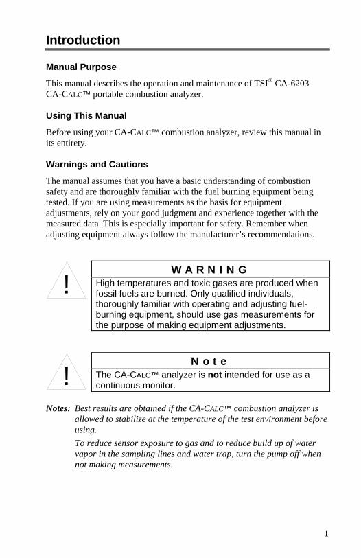
Warnings and Cautions
The manual assumes that you have a basic understanding of combustion safety and are thoroughly familiar with the fuel burning equipment being tested. If you are using measurements as the basis for equipment adjustments, rely on your good judgment and experience together with the measured data. This is especially important for safety. Remember when adjusting equipment always follow the manufacturer’s recommendations.
!
W A R N I N G
High temperatures and toxic gases are produced when fossil fuels are burned. Only qualified individuals, thoroughly familiar with operating and adjusting fuel-burning equipment, should use gas measurements for the purpose of making equipment adjustments.
!
N o t e
The CA-CALC™ analyzer is not intended for use as a continuous monitor.
Notes: Best results are obtained if the CA-CALC™ combustion analyzer is
allowed to stabilize at the temperature of the test environment before using.
To reduce sensor exposure to gas and to reduce build up of water vapor in the sampling lines and water trap, turn the pump off when not making measurements.

2
(This page intentionally left blank)

3
Chapter 1 Instrument Description
The Model CA-6203 CA-CALC™ combustion analyzer is used to evaluate the performance of burners in boilers, furnaces, and hot water tanks. The Model CA-6203 has sensors for the direct measurement of combustion gases; O2, CO, NO; combustion gas temperatures and draft pressure. The Model CA-6203 performs a complete list of combustion and emission parameters for a variety of system performance evaluations. Different units and different fuel types are readily selectable.
CA-6203 CA-CALCTM Combustion Analyzer Measurements and Calculations
Measurement Sensor Oxygen concentration O2, electrochemical Carbon monoxide CO, electrochemical Nitric oxide NO, electrochemical Flue temperature Thermocouple Supply air temperature On-board sensor or Thermocouple probe Draft pressure Pressure transducer, internal solid state Calculations CO2, Carbon Dioxide Excess air / λ Stack/Flue loss / qA Combustion efficiency Differential temperature NOx CO undiluted NO undiluted COr index NOx undiluted Emission Rates CO, NO The Model 6203 is supplied with a sampling probe having an in-line water trap and particulate filter. The Model 6203 operates using either an AC power supply or C-size batteries.

Chapter 1 4
The Model 6203 stores individual data samples (up to 100), and prints the data to a portable printer or computer. Stored data can be saved over a user-defined interval and averaged. The Model 6203 has a variety of standard fuels, and enables you to modify the fuel parameters, or install your own user-defined fuel. Loss and efficiency are calculated from standard ASME heat-loss calculations or using the Siegert formula (refer to Appendix B).

5
Chapter 2 Unpacking
Carefully unpack your CA-CALC™ combustion analyzer and accessories from the carrying case. Check the individual parts against the list of components in the table below. If items are missing or damaged, notify TSI immediately.
List of Standard Components
Qty. Item Component Part/ Model 1 Series CA-6203 CA-CALC™ combustion analyzer 1083618 1 Sample probe with water trap, draft line and
temperature 801989
1 Universal Power supply 7.2 V with assorted plug types
2182003
4 C cell alkaline batteries 1 Operation and Service manual 1980472
Accessories and Replacement Parts
Item Part/Model Combustion Supply Air thermocouple 3013003 Portable printer kit 801994 Computer cable 8940 Hard side Carrying case 1319319 CO replacement sensor 802014 O2 replacement sensor 802012 NO replacement sensor 802007 Water trap filters 801947 Calibration Kit O2 (N2 gas) and CO 802003 Calibration Kit CO 801999 Calibration Kit NO 801937 Replacement bottled gas, CO (requires Cal. Kit) 801941 Replacement bottled gas, NO (requires Cal. Kit) 801930 Replacement bottled gas, N2 (requires Cal. Kit) 801980 Bottled gas, CO with H2 (requires Cal. Kit) 801942

Chapter 2 6
(This page intentionally left blank)

7
Chapter 3 Component Identification
Key components of the CA-CALC™ combustion analyzer and sampling probe are identified in Figures 1 and 2, and under section headings in the text that follows.
1. Data buttons 9. Battery cover 2. LCD display 10. Battery cover tab 3. On-Off button 11. Port for flue gas thermocouple 4. Control buttons 12. Port for supply air thermocouple 5. Icon buttons 13. RS-232 serial port 6. Magnets 14. Power connection 7. Vent 15. Draft sample port 8. Sensor cover 16. Gas sample port
Figure 1: CA-6203 CA-CALC
TM Combustion Analyzer

Chapter 3 8
1. Tube retaining fitting 6. Thermocouple connector 2. Probe handle 7. Flexible sample line 3. Position collar 8. Water Trap 4. Sample tube 9. Water trap filter 5. Probe tip with thermocouple
Figure 2: CA-CALC™ Sampling Probe Components
The Gas Sensors
The CA-6203 CA-CALC™ analyzer uses three gas sensors for measuring oxygen (O2), carbon monoxide (CO) and nitric oxide (NO). CO and NO sensors are capable of operating from two to three years. The O2 sensor typically lasts one year. Best accuracy is obtained by routine user calibration (automatic for the O2 sensor). Calibrated replacement CO and NO sensors are also available from the factory.

Component Identification 9
The Sampling Probe
Your combustion analyzer comes equipped with a sampling probe, depicted in Figure 2. A thermocouple extends to the end of the sampling tube for making flue temperature measurements. Two flexible sampling lines are used for gas sampling and draft measurement. The sampling tube is removable for cleaning.
Flue Probe Thermocouple
The flue temperature (TS) is measured using a Type K probe, which extends through the sampling tube to the probe tip. The thermocouple probe measures temperatures up to 1000 degrees C (1800 degrees F).
On-Board Temperature Measurement
Your CA-CALC™ analyzer uses an on-board temperature detector to provide the Combustion Supply Air (TA) temperature when no supply-air accessory probe is present.
Diaphragm Pump
The CA-CALC™ analyzer samples exhaust gases from the flue and delivers them to the electrochemical sensors using a diaphragm sampling pump. Typical pump life is 5000 hours.
Draft Sensor
A differential pressure transducer in the CA-CALC™ analyzer is used to measure draft pressure.
Water Trap
The water trap, shown in Figure 2, is used to remove moisture that collects in the sample tubing when combustion gases are sampled. The water trap has a two-chamber design with a particulate filter.
Optional Combustion Supply Air Thermocouple Probe
A measurement of the Combustion Supply Air (TA) temperature at the source can be made using an optional thermocouple accessory probe (TSI PN 3013003). This probe is connected to the supply air temperature port shown in Figure 1. When a Supply Air temperature probe is not used, the supply air temperature is determined from the on-board temperature sensor.

Chapter 3 10
Schematic Representation of CA-CALC™ Analyzer
Figure 3. Schematic Representation of CA-CALC™ Analyzer

11
Chapter 4 Getting Started
Supplying Power
The CA-CALC™ portable combustion analyzer operates using 4 C batteries or an AC adapter. Quality alkaline batteries enable the instrument to operate for at least 24 hours. Use of the plug-in AC adapter conserves battery life, and can be substituted for batteries.
Installing Batteries
Turn the combustion analyzer over and remove the battery cover by lifting up and out on the battery cover tab shown below. Remove the old batteries. Note: It is not necessary to remove the
battery holder when removing or installing batteries. Best results are obtained if the batteries opposite the contact springs are removed first.
Install four new C-cell batteries, noting the battery orientation depicted on the base of the battery holder. Install spring-side batteries first.
Connecting the Sampling Probe
The sampling probe depicted in Figure 2, is connected to the instrument by pushing the brass sample and silver draft connectors over the ports on the instrument. Refer to the figures below showing the proper connection of the probe tubes to the instrument sample ports. Note that the thermocouple connector can be inserted only one way. The thermocouple connector is oriented with the large spade to the right. Do not force the connector.

Chapter 4 12
Figure 4: Sampling Probe Connections
Connecting the Optional Combustion Supply Air Temperature Probe
A type K thermocouple probe may be used to measure the temperature of the air supplied to the burner. Connect the optional supply air thermocouple (see “Accessories and Replacement Parts”) to the supply air thermocouple port depicted in Figure 1. The thermocouple connector can be inserted only one way—large spade to the right. Do not force the connector. When the optional Supply Air Temperature Probe is not used, supplied combustion air temperature is determined from the instrument temperature using an on-board sensor.
Connecting the Optional Portable Printer
Find the printer interface cable included with the optional portable printer. For the serial printer, connect the large 9-pin connector on the cable to mating connector on the printer. Connect the opposite end to the instrument’s RS-232 communications and printer port. See Figure 1 for port location. The printer and CA-CALC™ combustion analyzer have both been factory set for a baud rate of 1200. If baud rates are not matched, the printer will print random characters, question marks or asterisks. Printer settings are described in the printer manual, along with illustrations identifying the correct DIP-switch configuration. To set the CA-CALC™ baud rate and device settings, refer to Chapter 6, “MENU Options.”
Connecting to a Computer
Use the optional computer interface cable, Model 8940, to transfer (download) data serially from the CA-CALC™ analyzer to a computer. Your printer cable will not work for downloading to the computer. Connect the
Sample Connector (Brass)
Draft Connector (Silver)
Thermocouple Connector

Getting Started 13
large 9-pin connector on the computer interface cable to the 9-pin serial connector on your computer. Connect the opposite end to the instrument’s RS-232 communications and printer port. See Figure 1 for port location. Set the baud rate of the CA-CALC™ analyzer to that of your computer, as described in Chapter 6, “MENU Options.” The factory preset baud rate is 1200. Set the COMM option to COMP so serial data is formatted for output to the computer. The alternative is PRNTR, indicating output formatted for printer output. Press the PRINT button to send data to the computer.
Default Instrument Settings
The CA-CALC™ combustion analyzer uses a number of parameter settings for presenting measured data, performing calculations, and controlling instrument operation. These include the measurement units, the fuel used, the baud rate, and so on. When shipped, your instrument has factory preset parameter settings and the selection of E (English) as the Default language. When another language is chosen from the language MENU option, different settings are automatically installed. These are indicated in the table below. Specific settings are easily changed as described in Chapter 6, “MENU Options”. However, settings are reset to those listed below if the language is changed.
Factory Defaults and Language Selection
Language Selection E (Default) D, FI, S, N, I O2 % % CO PPM (parts per million) PPM Draft units Inches H2O mbar Temp units Degrees Fahrenheit Degrees Centigrade Excess Air %EA λ = %EA/100 +1 Effc./Loss basis ASME Siegert formula Effc./loss units % (net) % qA Fuel parameters C, H, H2O, HHV, CO2max A2 B Fuel list U.S. Fuels Siegert Fuels Fuel Natural Gas Natural Gas Baud Rate 1200 1200 Sampling interval 1 second 1 second Communications Printer format Printer format Time MM / DD / YY DD / MM / YY

Chapter 4 14
(This page intentionally left blank)

15
Chapter 5 Basic Operation
Buttons and Button Operations
ON-OFF Control Button Turns the instrument on and off.
The ENTER Control Button Press the ENTER button to execute a command, such as selecting a menu item.
The ESC Control Button Used to return to the previous screen or cancel a process.
ARROW Control Buttons Use the Left and Right arrow buttons to step between options. Use the Up and Down arrow buttons to change number values.
Button Indicators
Back Light ON/OFF
Pump ON/OFF
Make draft measurement
Zero draft transducer
Select fuel

Chapter 5 16
Data Buttons
Clear stored data
Review stored data
Save data
Startup
Remove the sampling probe from the flue or disconnect the sample tubing from the sampling port. Press the ON-OFF button. Refer to Figure 5 showing screens displayed during the start up sequence. If no errors are detected, the Main Data Display screen appears when the sequence is complete. Error codes are presented in Appendix A. ESC will bypass the error messages. While the WARM screen is displayed, the O2 sensor is automatically calibrated using ambient air, and the CO and NO sensors are zeroed. At the end of the WARM sequence (45 seconds), the pump stops and the draft sensor is zeroed. The WARM sequence can be bypassed by pressing the ESC button. Do this if a new O2 calibration and new zeros are not desired.

Basic Operation 17
Figure 5. Startup Sequence
Version Number
Model Number
Serial Number
Time and Date
Error Codes
Warm-up Countdown Main Data Display

Chapter 5 18
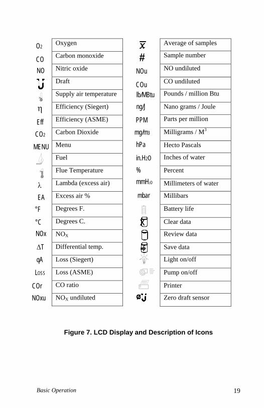
Characters and Display Icons
Refer to Figures 6 and 7 that follow. These identify the icons and characters found on the Model CA-6203 display. The display icons indicate measurements made, units, or functions performed. Some icons are not used with the Model CA-6203.
Figure 6. LCD Display Showing Icons
Basic Operation 19
Figure 7. LCD Display and Description of Icons
CO2
°C
LOSS
COrNOxu
qA ∆T
NOx
λ EA
°F
MENU
Eff
η
CONO
O2
mg/m3
mmH2O
x
mbar
hPa
in.H2O
%
COu
ng/J
lb/MBtu
PPM
NOu#
Average of samples
Sample number
NO undiluted
CO undiluted
Pounds / million Btu
Nano grams / Joule
Parts per million
Milligrams / M3
Hecto Pascals
Inches of water
Percent
Millimeters of water
Millibars
Battery life
Clear data
Review data
Save data
Light on/off
Pump on/off
Printer
Zero draft sensor
Oxygen
Carbon monoxide
Nitric oxide
Draft
Supply air temperature
Efficiency (Siegert)
Efficiency (ASME)
Carbon Dioxide
Menu
Fuel
Flue Temperature
Lambda (excess air)
Excess air %
Degrees F.
Degrees C.
NOX
Differential temp.
Loss (Siegert)
Loss (ASME)
CO ratio
NOX undiluted

Chapter 5 20
Measurements and Calculations
Oxygen Measurement
An O2 electrochemical sensor measures oxygen concentration in the range of 0 to 25%. The O2 measurement is also used to calculate the concentration of carbon dioxide (CO2) in the exhaust, and is used in calculations of combustion efficiency and undiluted CO and NO concentrations.
Carbon Monoxide Measurement
Carbon monoxide is measured in the range of 0 to 5000 PPM.
CO2 Measurement
%CO2 calculated from the O2 concentration in the flue. Refer to Appendix B for a description of the calculation.
NO Measurement
Nitric Oxide is measured in the range of 0 to 4000 PPM.
Flue/stack Temperature, TS
Flue temperature is measured with sampling probe.
Combustion Air Temperature, TA
Measurement of combustion air temperature is determined using the temperature probe accessory, TSI PN 3013003. In the absence of this probe, the combustion air temperature is assumed to be the instrument temperature, and determined from a temperature sensor in the instrument case.
ΔT, Temperature Difference
The flue/stack temperature minus the combustion air temperature.
Excess Air or Lambda (λ) Calculations of these values are found in Appendix B.
Loss
ASME based heat loss from the hot gases exiting the flue/stack. Includes latent heat loss from the formation of water vapor. See Appendix B.
Basic Operation 21
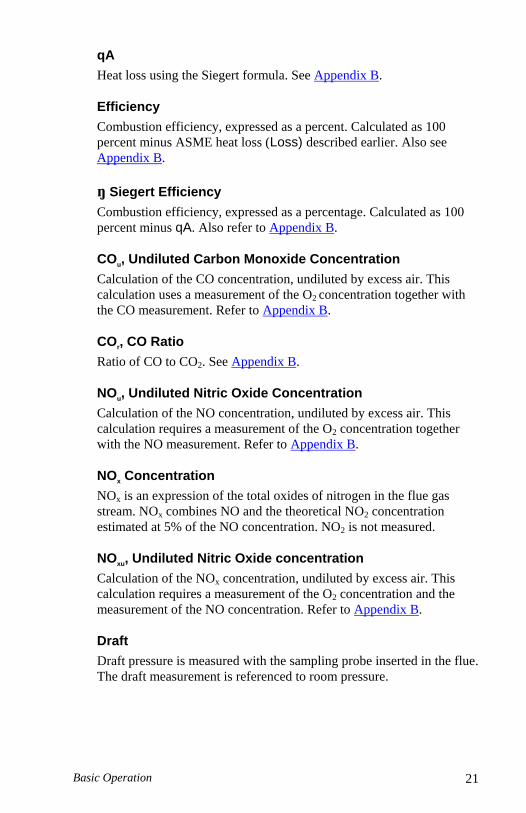
qA
Heat loss using the Siegert formula. See Appendix B.
Efficiency
Combustion efficiency, expressed as a percent. Calculated as 100 percent minus ASME heat loss (Loss) described earlier. Also see Appendix B.
ŋ Siegert Efficiency
Combustion efficiency, expressed as a percentage. Calculated as 100 percent minus qA. Also refer to Appendix B.
COu, Undiluted Carbon Monoxide Concentration
Calculation of the CO concentration, undiluted by excess air. This calculation uses a measurement of the O2 concentration together with the CO measurement. Refer to Appendix B.
COr, CO Ratio
Ratio of CO to CO2. See Appendix B.
NOu, Undiluted Nitric Oxide Concentration
Calculation of the NO concentration, undiluted by excess air. This calculation requires a measurement of the O2 concentration together with the NO measurement. Refer to Appendix B.
NOx Concentration
NOx is an expression of the total oxides of nitrogen in the flue gas stream. NOx combines NO and the theoretical NO2 concentration estimated at 5% of the NO concentration. NO2 is not measured.
NOxu, Undiluted Nitric Oxide concentration
Calculation of the NOx concentration, undiluted by excess air. This calculation requires a measurement of the O2 concentration and the measurement of the NO concentration. Refer to Appendix B.
Draft
Draft pressure is measured with the sampling probe inserted in the flue. The draft measurement is referenced to room pressure.
Chapter 5 22
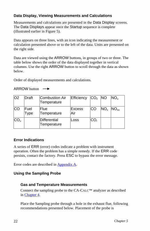
Data Display, Viewing Measurements and Calculations
Measurements and calculations are presented in the Data Display screens. The Data Displays appear once the Startup sequence is complete (illustrated earlier in Figure 5). Data appears on three lines, with an icon indicating the measurement or calculation presented above or to the left of the data. Units are presented on the right side. Data are viewed using the ARROW buttons, in groups of two or three. The table below shows the order of the data displayed together in vertical columns. Use the right ARROW button to scroll through the data as shown below. Order of displayed measurements and calculations. ARROW button O2 Draft Combustion Air
Temperature Efficiency CO2 NO NOu
CO Fuel Type
Flue Temperature
Excess Air
CO NOx NOxu
COu Differential Temperature
Loss COr
Error Indications
A series of ERR (error) codes indicate a problem with instrument operation. Often the problem has a simple remedy. If the ERR code persists, contact the factory. Press ESC to bypass the error message. Error codes are described in Appendix A.
Using the Sampling Probe
Gas and Temperature Measurements
Connect the sampling probe to the CA-CALC™ analyzer as described in Chapter 4. Place the Sampling probe through a hole in the exhaust flue, following recommendations presented below. Placement of the probe is

Basic Operation 23
important and certain considerations must be given when choosing a sampling location.
To ensure that the gas measurements are not diluted or cooled by outside air, place the probe before any draft damper or regulator as illustrated in Figure 8. Tilt the probe tip up slightly so vapor condensing in the sampling tube does not run back to the probe tip and cool the thermocouple tip. The sampling probe tip should be placed at the point of highest exhaust gas temperature. This means at the base of the flue, before heat is lost to the flue sidewalls, and towards the center, especially for small ducts. If the flue/stack gas temperature is underestimated, the operating efficiency will be overstated. When an economizer or air heater is used, the flue/stack temperature is measured after these devices Important: Orient the sampling tube to ensure that the thermocouple tip is exposed directly to exhaust flow (see Figure 8 below).
1. Sampling probe 3. Exhaust flue 2. Draft regulator 4. Hot exhaust gases
Figure 8: Sampling Probe Location
Chapter 5 24
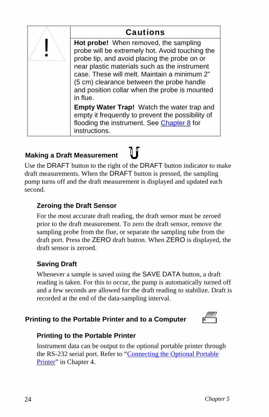
!
Cautions Hot probe! When removed, the sampling probe will be extremely hot. Avoid touching the probe tip, and avoid placing the probe on or near plastic materials such as the instrument case. These will melt. Maintain a minimum 2” (5 cm) clearance between the probe handle and position collar when the probe is mounted in flue. Empty Water Trap! Watch the water trap and empty it frequently to prevent the possibility of flooding the instrument. See Chapter 8 for instructions.
Making a Draft Measurement Use the DRAFT button to the right of the DRAFT button indicator to make draft measurements. When the DRAFT button is pressed, the sampling pump turns off and the draft measurement is displayed and updated each second.
Zeroing the Draft Sensor
For the most accurate draft reading, the draft sensor must be zeroed prior to the draft measurement. To zero the draft sensor, remove the sampling probe from the flue, or separate the sampling tube from the draft port. Press the ZERO draft button. When ZERO is displayed, the draft sensor is zeroed.
Saving Draft
Whenever a sample is saved using the SAVE DATA button, a draft reading is taken. For this to occur, the pump is automatically turned off and a few seconds are allowed for the draft reading to stabilize. Draft is recorded at the end of the data-sampling interval.
Printing to the Portable Printer and to a Computer
Printing to the Portable Printer
Instrument data can be output to the optional portable printer through the RS-232 serial port. Refer to “Connecting the Optional Portable Printer” in Chapter 4.

Basic Operation 25
To print the information on the Data Display, press the PRINT button, to the right of the print button icon. The printer responds immediately, producing a printout of the current data. An example of this printout is shown in Figure 9. Saved data can be printed too. Hold the Print button down until a countdown from three (3) begins. Release the button at zero (0), and all saved data is printed. Printing individual saved data samples is described in the next section, “Handling Data.”
Printing to a Computer
Use the PRINT button to output data to a computer as well as to the portable printer. Refer to “Connecting to a Computer” in Chapter 4. Data transferred to a computer is the same as that output to a printer (see Figure 9); however, it is formatted differently and uses the Windows® character set rather than DOS characters. You will need to set appropriate COMM MENU option before sending data to the computer. Refer to the Chapter 6, “MENU Options.” Data can be downloaded to a terminal emulator program such as the HyperTerminal, which accompanies the Windows® operating system program. Look for HyperTerminal in the Accessories folder. In HyperTerminal, use the Capture Text option from the Transfer menu for recording instrument data. Your instrument comes configured with the following communications protocol.
Communications Protocol
Baud rate 1200 (default) Data bits 8 Parity None Stop bit 1 Flow None
®Windows and Excel are a registered trademarks of Microsoft Corporation.

Chapter 5 26
Figure 9: Example Printout
-------------------------------- MODEL: 6203 SERIAL: ---------------------------------- Current Data --------------------------------- DATE: 01/01/06 TIME: 15:00:18 Fuel: Nat Gas Fuel Parameters: C: 75 H: 25 CO2MX: 11.8 KBTU: 23.8 H2O: 0 O2 6.0 CO 5 PPM NO: 0 PPM COu 7 PPM COr NA NO 40 PPM NOu 56 PPM NOx 42 PPM TA 70 °F TS 300 °F Draft 0.01 inH2O CO2 8.4 % Lambda OVER Effc 84% LOSS 16%

Basic Operation 27
Handling Data
Saving Data Up to one hundred (100) separate measurements can be made and saved to the instrument memory as data Samples. Press the SAVE DATA button located below the SAVE DATA icon at the bottom of the display. When SAVE DATA is pressed, measurements are sampled and averaged over the interval set in the INT.SA MENU option described in Chapter 6. As data is sampled, the sample number is displayed, and the save data icon blinks.
Note: The pump turns off while the draft is measured and saved.
CLEAR Data While in the Data Display screen, press and hold the CLEAR DATA button for three (3) seconds to erase all saved data from the instrument memory. The button must be released when zero is displayed. If the button is held longer than three (3) seconds, nothing is cleared. To clear the last Sample only, release the CLEAR data button before the end of the countdown, during 3, 2, or 1.
REVIEW Data Samples Press the REVIEW DATA button briefly to recall saved Samples. The number of the last Sample appears. Select the specific data Sample you wish to view using the ARROW buttons and press ENTER. When the Sample number (#) is displayed, use the ARROW buttons to review the different measurements.
Printing To print individual saved Samples, press the PRINT button while the saved Sample is shown. To print all saved Samples, hold the PRINT button down until a countdown from three (3) begins. Release the button at zero, (0) and all saved Samples are printed.
Averaging Saved Samples To average the last three (3) saved Samples, press and hold the REVIEW DATA for a couple of seconds. The screen blanks during this interval. When averaged, the X-bar icon appears indicating that the data presented is an average of the Samples. Data averaging works only from the main Data Display screen.

Chapter 5 28
(This page intentionally left blank)

29
Chapter 6 MENU Options
The Series 6203 CA-CALC™ instrument has a variety of user selectable parameters, available as MENU options. The user-selectable MENU options are shown in the schematic below. Press ENTER to access the MENU options from the Main Data Display screen. View the MENU options by using the right/left ARROW buttons. Once the screen of interest is displayed, press the ENTER button again to choose the MENU option. Use up/down buttons to change values. Refer to Figure 10, which shows the MENU options.
Figure 10. Menu Option
Press the ENTER button from the Main Display to enable the Menu options.
Use ENTER to select an option.
Press ESC to return to Data Display.

Chapter 6 30
BASE.L MENU—Option Update Sensor Baselines
Use the BASE.L MENU option to update the zero concentration baselines for your electrochemical sensors. Make sure the sampling probe is removed from the flue or disconnected from the instrument during zeroing. If ESC is pressed before zeroing is complete, previous baseline values are restored.
FUEL MENU Option—Select Fuel
Use the FUEL option to select from seven preset U.S. fuels or six Siegert fuels, or select the USER fuel. The fuels parameter list presented (U.S. or Siegert), is determined by the selection, LOSS or qA, respectively, made from the UNITS MENU option
Figure 11. FUEL Options
Menu Options 31
FP MENU Option—Fuel Parameters
See later.
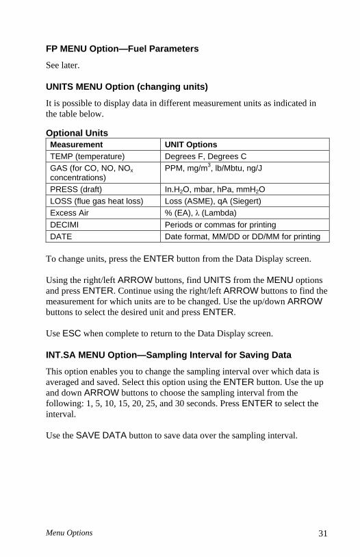
UNITS MENU Option (changing units)
It is possible to display data in different measurement units as indicated in the table below. Optional Units Measurement UNIT Options TEMP (temperature) Degrees F, Degrees C GAS (for CO, NO, NOx concentrations)
PPM, mg/m3, lb/Mbtu, ng/J
PRESS (draft) In.H2O, mbar, hPa, mmH2O LOSS (flue gas heat loss) Loss (ASME), qA (Siegert) Excess Air % (EA), λ (Lambda) DECIMI Periods or commas for printing DATE Date format, MM/DD or DD/MM for printing
To change units, press the ENTER button from the Data Display screen. Using the right/left ARROW buttons, find UNITS from the MENU options and press ENTER. Continue using the right/left ARROW buttons to find the measurement for which units are to be changed. Use the up/down ARROW buttons to select the desired unit and press ENTER. Use ESC when complete to return to the Data Display screen.
INT.SA MENU Option—Sampling Interval for Saving Data
This option enables you to change the sampling interval over which data is averaged and saved. Select this option using the ENTER button. Use the up and down ARROW buttons to choose the sampling interval from the following: 1, 5, 10, 15, 20, 25, and 30 seconds. Press ENTER to select the interval. Use the SAVE DATA button to save data over the sampling interval.
Chapter 6 32
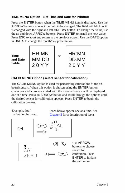
TIME MENU Option—Set Time and Date for Printout
Press the ENTER button when the TIME MENU item is displayed. Use the ARROW buttons to select the field to be changed. The field will blink as it is changed with the right and left ARROW button. To change the value, use the up and down ARROW buttons. Press ENTER to install the new value. Press ESC to abort and return to the previous screen. Use the DATE option in UNITS to change the month/day presentation. Time or and Date fields
CALIB MENU Option (select sensor for calibration)
The CALIB MENU option is used for performing calibrations of the on-board sensors. When this option is chosen using the ENTER button, characters and icons associated with the installed sensor will be displayed, one at a time. Press an ARROW button and scroll through the options until the desired sensor for calibration appears. Press ENTER to begin the calibration process.
HR:MN MM.DD 2 0 Y Y
HR:MN DD.MM 2 0 Y Y
Icons below appear one at a time. See Chapter 5 for a description of icons.
Use ARROW buttons to choose sensor for calibration. Press ENTER to initiate the calibration.
Example, Draft calibration initiated.

Menu Options 33
O2 Gas Sensor Calibration
The Oxygen (O2) sensor is SPAN calibrated in room air whenever the instrument is turned on and allowed to complete the Startup sequence. Using the BASE.L MENU option also spans the O2 sensor. Additional calibration is generally not required. Calibrating the O2 sensor is done to determine a new zero value (no O2 present) for the sensor. This is done if a drift in the sensor zero value is suspected. Select CALIB from the MENU options using the ENTER button. Select the O2 icon from the icons displayed using an ARROW button, and press ENTER. Attach the zero gas (nitrogen, N2) to the sampling probe as described in Chapter 7, “Setup for Gas Calibration.” When ready, press ENTER to begin the zero calibration. Once complete, the SPAN calibration screen appears. The O2 concentration can be adjusted using the ARROW buttons. If room air is used as the calibration gas, use the value displayed initially, 20.9%. Press the ENTER button to begin the SPAN calibration. Once complete, use the ESC button to return to the Data Display screen.
Calibration of the CO (hydrogen compensated) Sensor
The presence of hydrogen gas (H2) produces a false signal on electrochemical CO sensors. The CO sensor in your CA-CALC™ analyzer has a second internal sensor that detects the H2 concentration and enables the instrument software to subtract the error caused by the presence of hydrogen gas. You can elect to calibrate using both the CO and H2, or calibrate with CO only. In the second case the sensor retains the previous correction for H2.
Calibration Steps
From the MENU screen select the CALIB option. Press ENTER. Use the ARROW buttons to select the CO icon and press ENTER. Sampling from the room air, press ENTER to perform the ZERO calibration. When complete, connect your CO calibration gas as depicted in Chapter 7, “Setup for Gas Calibration.” Use the ARROW buttons and adjust the CO gas calibration number to match the concentration of your gas bottle. Press ENTER to initiate the CO calibration. Once complete, connect your calibration gas bottle containing both carbon monoxide and hydrogen (see note below). Use the ARROW buttons to adjust to the CO bottle concentration under the SPAN.CO heading, then press ENTER. Under the SPAN.H2 heading adjust the number using the ARROW buttons to match the hydrogen concentration. Press ENTER to start the calibration.

Chapter 6 34
Note: It is possible to do only the CO part of the calibration. To bypass the calibration using the combined CO and H2 bottle, press the ESC button after the CO portion of the calibration is complete.
!
CAUTION Toxic Gases!
Familiarize yourself with the toxic properties of the calibration gases by reading the supplied Material Safety Data Sheets (MSDS) accompanying the gas cylinders. Do not perform calibrations in a confined space. Make sure calibrations are performed in an area with proper ventilation, or under an exhaust hood.
NO Gas Sensor Calibration
From the MENU screen select the CALIB option. Press ENTER. Use the ARROW buttons to select the NO icon and press ENTER. Sampling from the room air, press ENTER to perform the ZERO calibration. When complete, connect your NO calibration gas as depicted in Chapter 7, “Setup for Gas Calibration.” Use the ARROW buttons and adjust the NO gas calibration number to match the concentration of your gas bottle. Press ENTER to initiate the NO calibration.
Draft Calibration
Span calibration of the draft sensor is normally not required. The draft sensor should be routinely zeroed, however, using the DRAFT ZERO button. This is especially important prior to making measurements at low draft pressures. When zeroing, make sure the sample probe is disconnected or that the probe is not in the flue.
Calibration Procedure
Required: An apparatus to provide stable calibration pressures of between plus 10–30 inches of water (25–75 hPa), and stable calibration pressures of between minus 10–30 inches of water (minus 25–75 hPa).
From the Main Data Display screen, press the ENTER button. Select CALIB from the MENU options presented using the ENTER button. Select the draft icon from the icons displayed using an ARROW button and press ENTER. Begin the calibration by pressing the ENTER button to perform a ZERO calibration. When the zero is complete, use the arrow buttons to adjust your positive supply reference pressure. Connect

Menu Options 35
your positive pressure to the draft port and press ENTER. Once the positive calibration is complete, connect your negative pressure reference to the draft port. Adjust the negative calibration pressure value using the ARROW buttons and press ENTER. Once the calibration is complete, use the ESC button to return to the main Data Display screen.
Temperature Calibration
Calibration of the flue and ambient thermocouple sensors is not recommended. Thermocouples are very repeatable, and even if replacement of a sampling probe is required, or a combustion air temperature probe is purchased as an accessory, it is unnecessary to calibrate it. Thermocouple accuracy can be improved for a specific temperature range if a calibration is preformed in that range. You will need to provide an accurate temperature reference. Refer to the steps below if calibration of a thermocouple is desired.
Calibration Procedure
Select the CALIB MENU option. Select the appropriate thermometer icon in the CALIB screen using the ARROW buttons. Install your sampling probe thermocouple or accessory thermocouple at the appropriate TS or TA connector. Press ENTER and set the calibration temperature to that of your supplied standard. Bring your thermocouple to the entered temperature and initiate the calibration by pressing ENTER.
CAL.FA MENU Option—Setting the Calibration Factor for a Replacement Gas Sensor
Install your new sensor as described in Chapter 8, “Maintenance and Troubleshooting.”
CO Sensor
Find the Calibration Factor sheet. Use the MENU option CAL.FA and press ENTER. Change the AVAL, BVAL, CVAL and DVAL to values on the calibration sheet using the up and down ARROW buttons. Follow each change by pressing the ENTER button. Figure 12 shows the steps. Pressing ESC takes you out of the entry sequence but keeps values which were saved with the ENTER button. Once complete, review entered values by stepping through the calibration factor screens using ENTER.

Chapter 6 36
Figure 12. Setting the Calibration Factor
NO Sensor
After installing your new sensor, as described in Chapter 8, “Maintenance and Troubleshooting,” find the NO calibration factor sheet. Use the ARROW buttons in the MENU option and find CAL.FA. Press ENTER. Use the ARROW buttons and select the NO sensor icon, press ENTER. Adjust the number displayed to match the value on the calibration sheet. Press ENTER to finish. Press the ESC button to return to the Data Display.
Use the ARROW buttons to find the CAL.FA MENU option. Press the ENTER button.
Choose the CO icon using the ARROW buttons and press ENTER.
Use ARROW buttons to change AVAL, BVAL, CVAL and DVAL calibration factors. Press the ENTER after changing each value.
CO icon
Complete, return with the ENTER button followed by ESC.
Menu Options 37
BAUD Rate MENU Option
Baud rate can be set to match your computer or portable printer. Your instrument is delivered with a default baud rate of 1200 to match the printer. Baud rate values are displayed in the BAUD rate MENU option divided by 1000. The following baud rates can be set. 1.2 (1200), 2.4 (2400), 4.8 (4800), 9.6 (9600), 19.2 (19200). To set the baud rate, select BAUD from the MENU option using the ENTER button. Step through the BAUD rates using the ARROW buttons and choose the desired value with the ENTER button. Use the ESC button to return.
COMM MENU Option—Set the Output Communications Device
Your CA-CALC™ analyzer transfers current or saved data to a serial printer or computer. The COMM MENU option is used to select the device that you want to communicate with. Failure to select the correct device may cause incorrect characters to appear on your printout or computer file. COMM options are COMP and PRNTR, for computer and printer, respectively. Set the device COMM from the MENU options using the ENTER button. Use the ARROW buttons and choose the desired option followed by pressing the ENTER button. Use the ESC button to return.
FP MENU Option—Fuel Parameters
U.S. Fuel Parameters
Note: For U.S. fuels and fuel parameters to be displayed, the fuel heat LOSS selection must be set to Loss, not qA. Refer to the section “UNITS MENU Option (changing units)” in this chapter.
For calculations of flue losses, maximum %CO2, fuel composition and fuel heat content are used. These are the Fuel Parameters. In your CA-CALC™ analyzer, U.S. fuel parameters are the carbon and hydrogen content, moisture content, sulfur content, and maximum %CO2, CO2MX.

Chapter 6 38
Figure 13. Fuel Parameters for U.S. Fuels.
Press ENTER button from the Data Display screen. Find FP using the ARROW buttons.
Press ENTER to access the fuel parameter list. Find the parameter to change using the ARROW buttons.
Change the parameter value using the ARROW buttons. Press the ENTER button to accept the new value. Press ESC to abort. The example to the right is for changing the hydrogen fuel percent.

Menu Options 39
Refer to the diagrams (Figures 13 and 14) and tables below for information on viewing and changing fuel parameters. Your CA-CALC™ analyzer has parameters for seven common U.S. fuels in instrument memory. Fuel parameters for these fuels can be changed, if you know, for example, that your fuel has a different composition than that stored. The instrument fuel parameters values are presented in Appendix B, with additional technical information.
Fuel Parameter Description C % carbon by weight H % hydrogen by weight H2O % moisture content by weight S % sulfur by weight CO2MX CO2 maximum % KBTU Heating value in kiloBTUs, (BTU/1000) F.CO F.NOx Emission Factors
FP Fuel Parameters for Siegert Calculation—Siegert Fuel Parameters
Note: For Siegert fuels and fuel parameters to be displayed, the fuel heat LOSS selection must be set to qA not LOSS. Refer to the section “UNITS MENU Option (changing units)” in this chapter.
The Siegert value for flue loss, given the designation qA, is used widely in Europe. Two coefficients are used in the Siegert formula for flue loss, derived from typical fuel compositions. These are given the designations, A2 and B.
Fuel Parameter Description A2 Siegert factor, fuel specific B Siegert factor, fuel specific CO2MX CO2 maximum % F.CO F.NOx Emission Factors

Chapter 6 40
The default Siegert coefficient values in your CA-CALC™ analyzer, are those used in Germany. Siegert coefficients used in other countries may be different, reflecting differences in local fuel compositions. Figure 25 diagrams the steps in changing the Siegert fuel parameters.
Figure 14. Changing Fuel Parameters for Siegert Fuels
LANG MENU Option
Use this option to select between the following languages: E English, D German, N Dutch, FI Finish, I Italian or S Swedish. English is the language (default) initially installed on the instrument. When the language is changed, instrument settings are automatically changed too. Refer to Chapter 4 “Default Instrument Settings” for more information on this feature.

41
Chapter 7 Setup for Gas Calibration
The Calibration Setups
Note: To perform your gas sensor calibration, you will also need to refer back to Chapter 6, and the section, “CALIB MENU Option.”
CO, NO and O2 gas sensors can be calibrated periodically to maintain the best accuracy. Gas sensors do drift over time, depending upon the operating environment and gas exposure history. CO and NO gas sensors can lose sensitivity by as much as by 10% per year. Since O2 sensors are calibrated in room air, loss in sensitivity poses no real problem. However, a drift in the zero (no O2 present) can occur, impacting the accuracy when measuring low O2 concentrations. With the proper equipment, such as that shown in the figures below, it is easy to calibrate your CA-CALC™ analyzer gas sensors. However, if you wish, you may also return your instrument to TSI for a new factory calibration. The equipment needed to calibrate individual gas sensors can be purchased from TSI as calibration kits. Model numbers for these kits are found in Chapter 2, “Unpacking.” You may also elect to put together your own calibration system. Two calibration setups are presented in Figures 26 and 27. A brief discussion of these calibration setups is presented in the following section.

Chapter 7 42
Figure 15. Calibration with TSI Calibration Kit
A TSI supplied calibration kit (Figure 15) uses a demand flow regulator to supply gas to the CA-CALC™ analyzer in response to the draw of the instrument sampling the pump. If a conventional regulator and valve are used (Figure 16), the setup requires a tee to a bleed-off extra gas. This prevents a forced flow at the instrument inlet. The bead-type flow meter depicted in the figure is used to verify there is extra flow (.5 to 2 L/min recommended). Extra flow is required to prevent room air from being drawn in, diluting the sample.

Setup for Gas Calibration 43
Figure 16. Alternative Calibration Setup

Chapter 7 44
(This page intentionally left blank)

45
Chapter 8 Maintenance and Troubleshooting
For additional troubleshooting information, please visit TSI’s website http://combustion.tsi.com. Emptying Water Trap
Refer back to Figure 2 showing the water trap in the sample line and to Figure 17. Liquid water forms in the first chamber of the water trap as gases are sampled from the flue. The water trap is designed so even when shaken, or when its orientation is changed, water does not pass to the second chamber. The water level must remain below the level depicted in the figure, however.
To empty the water trap:
1. First separate it from the sampling tube by pulling the tube ends off the barbs on the end caps.
2. Remove the probe side end cap by pulling outward with a twisting motion.
3. Pour out the water and replace the end cap. Re-install the trap. Important: Make sure the water trap is oriented so that end-cap 1 below is toward the instrument.
Changing the Water Trap Filter
Identify the water trap filter (refer to Figure 17). This filter is designed to remove soot particles before they contaminate the instrument. The filter can be removed for cleaning or replacement by following these steps:
1. Remove the instrument side end cap by pulling it out with a twisting motion.
2. Grasp the filter using a needle-nose pliers and pull it out.
3. To clean the filter, remove the bulk of the soot by tapping the filter. The soot may be removed by rinsing with water or isopropyl alcohol. The effectiveness of the rinse depends on the soot composition—is it dry or oily. Avoid rubbing, which may drive contaminates into the filter causing permanent plugging.

Chapter 8 46
4. Whether cleaned or replaced, install the filter by pushing it over the stub in the filter body, then replace the end cap.
1. Instrument side end-cap 2. First chamber 3. Probe side end-cap 4. Polycarbonate trap body 5. Second chamber 6. Plastic filter 7. Maximum water level
Figure 17: In-line Water Trap
Cleaning the Sample Probe
Cleaning may be necessary in high-soot environments. Soot accumulates in the steel sampling tube and sampling line and over time may contribute to a blocked flow path.
1. Remove the water trap by separating the sample tube from the tube stub on each end of the trap.
2. Rinse the tubing, allowing the water to drain from the probe end. When the water is clear, discontinue the rinse. Orient the probe and tubing so excess water drains from the sample lines.
3. Allow adequate time for the interior of the probe to dry. Replace the water trap making sure the water trap is oriented properly. The filter must be toward the instrument.
Lithium Battery Replacement
The lithium battery supports measurement data saved in memory. Typical battery life is three years. An ERR code 63 indicates a low lithium battery. To replace the battery open the battery compartment and remove the C-cell battery holder. Find the ½ AA lithium battery after removing the white foam battery retainer. Replace the battery in the correct plus/minus orientation. Replace the white foam retainer, C-cell holder and battery cover.

Maintenance and Troubleshooting 47
Replacing a Gas Sensor
Remove the sensor cover identified in Figure 1 (8). From the left side, pry back the black rubber sensor cups to expose the gas sensors. Do not separate any fittings connected to the rubber cups. To remove a senor, grasp the sensor and lift straight up. When installing a sensor, note the orientation of the sensor pins at the bottom of the sensor and the orientation of the receptacles in the instrument. Tilt the sensor, aligning the base pin with the base receptacle and the right pin with the right receptacle. Once aligned, stand the sensor up and push in. When installed properly, the sensor will not twist. Calibration factor: when installing a replacement CO or NO sensor from TSI, enter the calibration factors for the sensor as described in Chapter 6, “CAL.FA MENU Option.”
Figure 18. Sensor and Sensor Cup Assembly
Left Side
Rubber Sensor Cups
Receptacles for Sensor Pins
Right Receptacle

Chapter 8 48
(This page intentionally left blank)

49
Appendix A Error Codes
Note: An Error Code can be bypassed using the ESC button. 7) Error in logged data. 9) Can't save data to EEPROM. 10) Fuel type changed to Natural Gas (fuel and LOSS type mismatch) 11) An invalid fuel parameter was corrected. 12) Model number checksum error. 13) TA thermocouple checksum error. 14) TS thermocouple checksum error. 15) Draft sensor checksum error. 16) A/D calibration checksum error. 17) CO sensor checksum error. 18) O2 sensor checksum error. 19) NO sensor checksum error. 50) O2 zero voltage out of range. 51) CO zero voltage out of range. 52) COAUX zero voltage out of range. 53) NO zero voltage out of range. 54) TA sensor zero voltage out of range. 55) TS sensor zero voltage out of range. 56) Instrument temperature out of range. 57) Draft zero voltage out of range. 58) Draft gain calibration out of range. 59) O2 span (baseline) voltage out of range. 60) Error in CO sensor-present test. 61) Error in COAUX sensor-present test. 62) Error in NO sensor-present test. 63) Lithium battery voltage is low. 64) TA sensor gain factor out of range. 65) TS sensor gain factor out of range. 66) NO sensor gain factor out of range. 67) CO sensor A_VALUE out of range. 68) CO sensor B_VALUE out of range. 69) CO sensor C_VALUE out of range. 70) CO sensor D_VALUE out of range. 71) Instrument temperature sensor offset factor out of range. 72) AtoD converter gain factor out of range. 73) Pump vacuum out of range. 74) or higher: Internal program error-contact TSI.

Appendix A 50
(This page intentionally left blank)
51
Appendix B Calculations
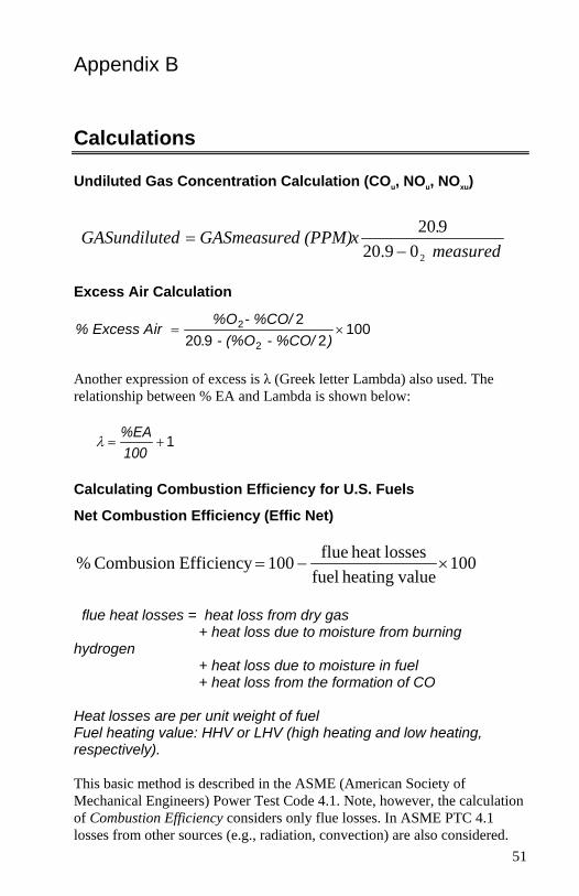
Undiluted Gas Concentration Calculation (COu, NOu, NOxu)
measured.xd (PPM)GASmeasureted GASundilu
209.20920
−=
Excess Air Calculation
1002920
2
2
2 ×=) - %CO/ - (%O.
- %CO/%Oir % Excess A
Another expression of excess is λ (Greek letter Lambda) also used. The relationship between % EA and Lambda is shown below:
1+=100%EA
λ
Calculating Combustion Efficiency for U.S. Fuels
Net Combustion Efficiency (Effic Net)
100 valueheating fuel
lossesheat flue100 EfficiencyCombusion % ×−=
flue heat losses = heat loss from dry gas + heat loss due to moisture from burning hydrogen + heat loss due to moisture in fuel + heat loss from the formation of CO Heat losses are per unit weight of fuel Fuel heating value: HHV or LHV (high heating and low heating, respectively). This basic method is described in the ASME (American Society of Mechanical Engineers) Power Test Code 4.1. Note, however, the calculation of Combustion Efficiency considers only flue losses. In ASME PTC 4.1 losses from other sources (e.g., radiation, convection) are also considered.

Appendix B 52
Fuel Parameters for U.S. Fuels Fuel Parameters
NATG, Methane
PROP, Propane
OIL2, Oil #2
OIL6, Oil #6
COAL
WOOD
COKE
%C (carbon) 75 81.8 85.84 87.49 94.5 51.8 98.2
%H (hydrogen) 25 18.18 12.46 9.92 5.2 6.3 1.5
KBTU/lb HHV 23800 21600 19500 18300 13400 9100 16.5
CO2 max 11.8 13.8 15.6 16.5 17 19.1 20.1
%S (sulfur) 0 0 1.6 1.40 0.034 0 0
%H2O (moisture) 0 0 0 0 0.12 0 .5
Siegert Formula
This formula is widely used in Europe to determine flue gas losses (qA) and efficiency.
( ) BO
ATa) x(Ts qA
+
−−=
2212
Efficiency = 100 – qA where: qA = dry gas losses Ts = flue temperature Ta = supply air temperature O2 = measured volumetric oxygen concentration expressed as a percent A2, B = fuel dependent constants The constants A2 and B are based on the composition of combustibles in the fuels. In Germany, the following prescribed values are provided for common fuels. Fuel Parameters for Siegert Fuels Fuel Type A2 B NATG, Natural gas .66 .009 OIL2, light fuel oil .68 .007 OIL6, heavy oil .68 .007 TGAS, Town gas .63 .011 CGAS, Coking oven gas .60 .011 PROP, propane .63 .008

Calculations 53
Determining CO2 Using the O2 Concentration
20.9measured) %O- (20.9
max CO volume) (by OC % 222 ×=
CO2max is the theoretical maximum concentration produced for the fuel used.
Emission Rate Calculations Using Emission Factors
Emission rate expresses the CO and NOx concentrations in units of mass of effluent per amount of energy (fuel) consumed (lb./Mbtu or ng/J). Since fuel energy differs from fuel to fuel, emissions, expressed in PPM for example, must be converted using a fuel specific parameters. This is where the Emission Factors F.CO and F.NOx are used. The emission rate calculation presented below is described in EPA Method 19. This uses the dry gas factor Fd. Dry factors are incorporated into the values found in the Table I, below. The table values (Ft), convert the measured concentrations of emission gases, CO, NOX, and SO2 from PPM to pounds per million Btu of fuel. Note: The bracketed quantity converts the emission rate to the undiluted value.
−
×=measured O 20.9
20.9Ft Cg2
E (undiluted)
where:
E = Emission Rate (pounds/MBtu of fuel, ng/J) Cg = Gas Concentration (PPM) Ft = factor from Table I (below) O2 measured = Oxygen concentration from flue measurement (%)
Emission Rate Factors
Factor (Ft)
Nat. Gas
Propane
Oil #2
Oil #6
Coal
Wood (dry)
Bagasse
Coke
F.NOx .00104 .00104 .00110 .00110 .00118 .00110 0.001 0.00118
F.CO .00063 .00063 .00067 .00067 .00072 .00067 0.00067 0.00072
Ft units: lb./MBtu PPM For those familiar with Method 19, Ft is related to Fd in the following way: Ft, in units lbs/(MBtu ppm) Fd, in units scf/MBtu Ft = Fd x lb/(scf ppm)

Appendix B 54
Important Note The Emission Rate factors shown in the table above are always expressed in units of lb./MBtu PPM regardless of whether the instrument is configured to display lb./MBtu or ng/J. This is important to recognize if entering your own factors.
A General Equation for the Combustion of a Simple Hydrocarbon in Air
OHy
COO4
y 4xHC 2yx 22 2
+⇒
+
+
x and y are the number of atoms of carbon and hydrogen in the fuel.
Calculating CO2 Max From the Carbon Content
1002 ×+
=N2)moles CO(moles
COmoles maxCO%
2
2
moles CO2 = x moles
43.76y)(4x
N moles×+
=2
Calculation of Combustion Air Requirement
Pounds Air / Pound Fuel = 11.5C + 34.3(H2 - O2/8) + 4.3S C, H2, O2 and S are the fractions, by weight, of each chemical constituent of the fuel.

55
Appendix C Series CA-6203 CA-CALCTM
Combustion Analyzer Specifications*
Oxygen (O2) Sensor Type .............................Electrochemical Range: ......................................0–25% Accuracy: ..................................±0.3% O2 Resolution: ................................0.1% O2 Response Time: ........................<30 seconds to 90% of step change
Carbon Monoxide (CO) Sensor Type .............................Electrochemical Range: ......................................0–5000 ppm Accuracy: ..................................0–100 ppm ±5 ppm or 10% of reading 100–5000: ±10 ppm or 5% Resolution: 1 ppm Response Time: ........................<30 seconds to 90% of step change
Sampling Probe Hose length...............................7.5’ std (2.4 m) Probe diameter: ........................5/16” (0.8 cm)
Nitric Oxide(NO) Sensor Type .............................Electrochemical Range: ......................................0–4000 ppm Accuracy: ..................................0–100 ppm ±5 ppm or 10% of reading 100–4000: ±10 ppm or 5% Resolution: 1 ppm Response Time: ........................<30 seconds to 90% of step change
Flue/stack Temperature Range ......................................0–1000°C. Resolution ................................1°C Accuracy ..................................±2°C, or .5% of reading
Supply Air Temperature Probe Range ......................................-40–150°C. Resolution ................................1°C Accuracy ..................................±1°C or 1%
Draft Range ......................................±30”H2O (±80mbar) Resolution ................................±.0.01”H2O Accuracy ..................................±1%rdg or .01”H2O (zeroed)
*Specifications are subject to change without notice. Specification giving lowest accuracy is applied.

Appendix C 56
External Dimensions: ............ 6” x 10” x 2.5”
Communication Interface: Type: ........................................ Serial Baud rate: ................................. 1200–19200 selectable
Power Requirements: Batteries: ............................. 4 C cell alkaline batteries Battery life: .......................... >24 hours (pump on) AC Adapter: ........................ Use only TSI-supplied adapter Backup battery: ................... Lithium Backup battery life: .............. 3 yrs Note: These specifications assume the instrument is allowed to stabilize at the operating temperature before being turned on.

TSI Incorporated – 500 Cardigan Road, Shoreview, MN 55126 U.S.A USA Tel: +1 800 874 2811 E-mail: [email protected] Website: www.tsi.com UK Tel: +44 149 4 459200 E-mail: [email protected] Website: www.tsiinc.co.uk France Tel: +33 491 11 87 64 E-mail: [email protected] Website: www.tsiinc.fr Germany Tel: +49 241 523030 E-mail: [email protected] Website: www.tsiinc.de India Tel: +91 80 41132470 E-mail: [email protected] China Tel: +86 10 8251 6588 E-mail: [email protected] Singapore Tel: +65 6595 6388 E-mail: [email protected] Contact your local TSI Distributor or visit our website www.tsi.com for more detailed specifications.
P/N 1980472 Rev C Copyright © 2010 by TSI Incorporated Printed in U.S.A.