cab kit installation instructions -...
TRANSCRIPT

Cab Kit Installation Instructions
Low Speed Vehicles (LSV) Electric Vehicles:
• Carryall 2• Carryall 6
Publication103507701
Edition Code0408E1209D
These instructions apply to the following kit:103463701

GENERAL INFORMATION AND PRECAUTIONS
This instruction provides detailed instructions for the installation of the cab kit. These instructions pertain toLSV Carryall 2 and Carryall 6 electric vehicles.
Order the following accessories separately
• Door Kit, CCI P/N 103463801.
• Rear Window Kit, CCI P/N 103463901.
• Heater/Defroster Kit, CCI P/N 103498901.
NOTE: Nylon washers have been supplied to provide a weather seal around all exterior hardware. A nylonwasher must be installed under each bolt head, directly against the cab exterior. Overtighteninghardware could damage the nylon washers.
Thoroughly review this document before performing any installation procedures.
The following safety statements relate to specific safety issues and must be read, understood, and heededbefore a kit is installed. Failure to do so could result in personal injury and/or property damage.
ý DANGER
• Battery – Explosive gases! Do not smoke. Keep sparks and flames away from the vehicle andservice area. Ventilate when charging or operating vehicle in an enclosed space. Wear a fullface shield and rubber gloves when working on or near batteries.
• Battery – Poison! Contains acid! Causes severe burns. Avoid contact with skin, eyes, orclothing. Antidotes:
- External: Flush with water. Call a physician immediately.
- Internal: Drink large quantities of milk or water. Follow with milk of magnesia or vegetableoil. Call a physician immediately.
- Eyes: Flush with water for 15 minutes. Call a physician immediately.
• Gasoline – Flammable! Explosive! Do not smoke. Keep sparks and flames away from thevehicle and service area. Service only in a well-ventilated area.
• Do not operate gasoline vehicle in an enclosed area without proper ventilation. The engineproduces carbon monoxide, which is an odorless, deadly poison.
• A Club Car vehicle will not provide protection from lightning, flying objects, or other storm-related hazards. If caught in a storm while driving a Club Car vehicle, exit the vehicle and seekshelter in accordance with applicable safety guidelines for your location.
ý WARNING
• Follow the procedures exactly as stated in this instruction, and heed all DANGER, WARNING,and CAUTION statements in this instruction as well as those on the vehicle and batterycharger.
WARNING CONTINUED ON NEXT PAGE...
Copyright © 2009 Club Car, Inc.
Page 2 Cab Kit Installation Instructions (103507701)

ý WARNING
• Club Car electric vehicles are designed without a chassis ground. Failure to maintain thischassis isolation could result in a potential fire hazard.
• Only trained technicians should service or repair the vehicle or battery charger. Anyone doingeven simple repairs or service should have knowledge and experience in electrical andmechanical repair. The appropriate instructions must be used when performing maintenance,service, or accessory installation.
• Prior to servicing the vehicle or leaving the vehicle unattended, turn the key switch OFF,remove the key, set the park brake, and place the Forward/Reverse handle in the NEUTRALposition. Chock the wheels when servicing the vehicle.
• Ensure battery connections are clean and properly tightened.
• To avoid unintentionally starting the vehicle, disconnect the batteries as shown (Figures 1through 2, starting on page 6).
• Place Tow/Run switch in the TOW position before disconnecting or connecting the batteries.Failure to heed this warning could result in a battery explosion or severe personal injury.
• After disconnecting the batteries, wait 90 seconds for the controller capacitors to discharge.
• Use only 2-gauge (AWG) wires with low-resistance terminals to replace battery wires.
• Wear safety glasses or approved eye protection when servicing the vehicle or battery charger.Wear a full face shield and rubber gloves when working on or near batteries.
• Do not wear loose clothing or jewelry such as rings, watches, chains, etc., when servicing thevehicle or battery charger.
• Moving parts! Do not attempt to service the vehicle while it is running.
• Hot! Do not attempt to service hot engine, exhaust system, or motor. Failure to heed thiswarning could result in severe burns.
• Use insulated tools when working near batteries or electrical connections. Use extremecaution to avoid shorting of components or wiring.
• Lift only one end of the vehicle at a time. Use a suitable lifting device (chain hoist or hydraulicfloor jack) with 1000 lb. (454 kg) minimum lifting capacity. Do not use lifting device to holdvehicle in raised position. Use approved jack stands of proper weight capacity to support thevehicle and chock the wheels that remain on the floor. When not performing a test or serviceprocedure that requires movement of the wheels, lock the brakes.
• If wires are removed or replaced, make sure wiring and wire harness are properly routed andsecured. Failure to properly route and secure wiring could result in vehicle malfunction,property damage, personal injury, or death.
• For vehicles with cargo beds, remove all cargo before raising the bed or servicing the vehicle.If the vehicle is equipped with a prop rod, ensure that it is securely engaged while bed israised. Do not close bed until all persons are clear of cargo bed area. Keep hands clear of allcrush areas. Do not drop cargo bed; lower gently and keep entire body clear. Failure to heedthis warning could result in severe personal injury or death.
Cab Kit Installation Instructions (103507701) Page 3

TOOLS REQUIRED
PARTS IN THIS KIT
NOTE: Replacement parts for cab may be obtained from Curtis Tractor Cab, Inc. 111 Higgins St., Worces-ter, MA 01606. Telephone (508) 853-2200 or fax (800) 876-9104.
1/2-INCH SOCKET
7/16-INCH SOCKET
1/2-INCHOPEN END WRENCH
7/16-INCHOPEN END WRENCH
PLIERS RATCHET
ELECTRIC DRILL
7/16-INCH DRILL BIT
5-50 FT-LBTORQUE WRENCH
PHILLIPS HEADSCREWDRIVER
3/16-INCHALLEN-HEAD
DRIVER
MIRRORMOUNTING
GLUE
SPACERS
CENTER HIGH-MOUNTSTOP LIGHT
MIRROR
EXTERIORMIRRORROOF SUPPORT
BRACKET (3)
ROOF
REAR CROSS BRACE
WINDSHIELD SUPPORT
REAR PANEL
FRONT COWL
FRONT COWLGASKET
FILLER(PASSENGER
SIDE)
FRONT MOUNTINGBRACKET
(DRIVER SIDE)
FILLER(DRIVER
SIDE)
FRONT MOUNTINGBRACKET
(PASSENGER SIDE)
REAR MOUNTING BRACKET
(DRIVER SIDE)
SIDE FRAME(PASSENGER SIDE)
SIDE FRAME (DRIVER SIDE)
REAR MOUNTING BRACKET
(PASSENGER SIDE)
WEATHER STRIPPING
WINDSHIELD
Page 4 Cab Kit Installation Instructions (103507701)

PARTS IN THIS KIT
5/16-18 x 3/4 CARRIAGE BOLT
WIPERMOTOR
5/16-18 x 1-1/2PHILLIPS-HEAD
MACHINE SCREW
1/4-20 x 1-1/2HEX-HEAD
BOLT
1/4-20 x 1-1/4HEX-HEAD
BOLT
1/4-20 x 1HEX-HEAD
BOLT
1/4-20 NYLONLOCKNUT
RUBBERWASHER
5/16 ID X 1 ODFENDERWASHER
1/4 FLATWASHER
5/16-18 x 3/4ALLEN-HEAD BOLT
5/16-18 x 1ALLEN-HEAD BOLT
7/16 NYLONWASHER
5/16-18 NYLONLOCKNUT
5/16 WASHER
WIPER ARM
WIPERSHAFT
HARDWARE
WIPERMOUNTINGHARDWARE
WIPER BLADE
LARGE FLATWASHER
7/16-14 LOCKNUT
SEAT BELT KIT
SEAT BELTRECEIVER LATCH
MOUNTING BRACKET SEAT BELT 7/16-14 x 1HEX-HEAD
BOLT
7/16 FLATWASHER
NYLON BUSHINGS FOR WIPER MOTOR
AIR VENT
Cab Kit Installation Instructions (103507701) Page 5

1. DISCONNECT THE BATTERY CABLES
1.1. Disconnect the battery cables as instructed. See "To avoid unintentionally starting..." WARNINGon page 3..
Figure 1 Battery Cable Removal – Electric Vehicle Battery Configuration
Carryall 2 LSV
Figure 2 Battery Cable Removal – Electric Vehicle Battery Configuration
Carryall 6 LSV(Viewed from driver side of vehicle)1. Place TOW/RUN Switch in TOW before disconnecting or connecting battery cables.2. Remove negative battery cable.3. Remove positive battery cable.Connect battery cables in reverse order.
(Viewed from driver side of vehicle)1. Place TOW/RUN Switch in TOW before disconnecting or connecting battery cables.2. Remove negative battery cable.3. Remove positive battery cable.Connect battery cables in reverse order.
1
8
2
3
4
5
6
7
1
2
BATTERY EXPLOSION COULD RESULT IN
SEVERE PERSONAL INJURY.
3
2
1
(+)
(–)
1
3
5
7
8
2
4
6
1
2
BATTERY EXPLOSION COULD RESULT IN
SEVERE PERSONAL INJURY.
3
2
1
(+)
(–)
Page 6 Cab Kit Installation Instructions (103507701)

2. SECURE FRONT MOUNTING BRACKETS
2.1. If vehicle has cup holders mounted to the dash, remove them and mount them to the other two holesin the dash.
2.2. Secure the front mounting brackets (1 and 2) under the dash with two 1/4-20 x 1 hex-head bolts (3),two washers (4), and two lock nuts (5) each as shown (Figures 3 and 4). Do not tighten hardware atthis time.
3. SECURE REAR MOUNTING BRACKETS TO SIDE FRAMES
3.1. Secure the seat belt (2) to the passenger-side rear mounting bracket (7) with one 7/16-14 x 1 hex-headbolt (1) and lock nut (3) as shown (Figure 5). Tighten hardware to 50 ft-lb (67.8 N·m).
3.2. Secure passenger-side rear mounting bracket (7) to passenger-side frame with one 5/16-18 x 3/4 car-riage bolt (9), flat washer (10), and lock nut (11) (Figure 5). Tighten hardware to 17 ft-lb (23.0 N·m).
3.3. Repeats steps 3.1 and 3.2 on the driver-side mounting bracket (8).
Figure 3 Install Passenger-Side FrontMounting Bracket
Figure 4 Install Driver-Side Front Mounting Bracket
Figure 5 Secure Rear Mounting Bracket(Passenger-side shown)
3
1
4
5
3
2
4
5
11
7
9
10
1
2
3
Cab Kit Installation Instructions (103507701) Page 7
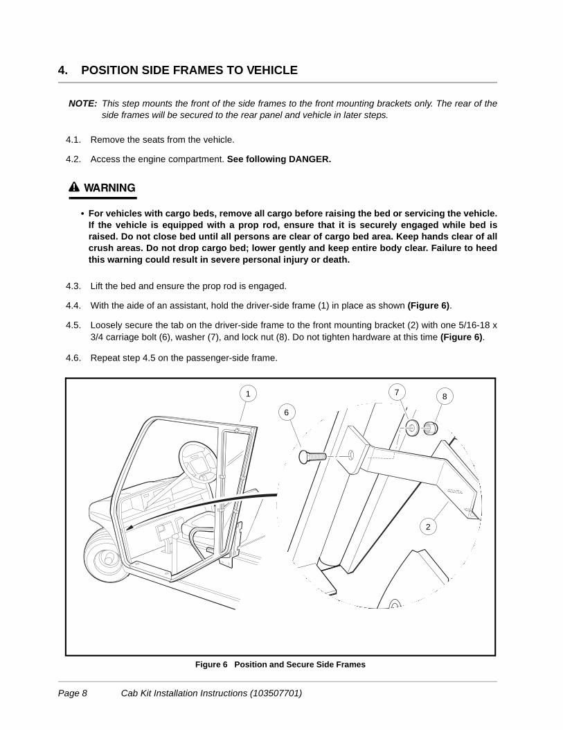
4. POSITION SIDE FRAMES TO VEHICLE
NOTE: This step mounts the front of the side frames to the front mounting brackets only. The rear of theside frames will be secured to the rear panel and vehicle in later steps.
4.1. Remove the seats from the vehicle.
4.2. Access the engine compartment. See following DANGER.
ý WARNING
• For vehicles with cargo beds, remove all cargo before raising the bed or servicing the vehicle.If the vehicle is equipped with a prop rod, ensure that it is securely engaged while bed israised. Do not close bed until all persons are clear of cargo bed area. Keep hands clear of allcrush areas. Do not drop cargo bed; lower gently and keep entire body clear. Failure to heedthis warning could result in severe personal injury or death.
4.3. Lift the bed and ensure the prop rod is engaged.
4.4. With the aide of an assistant, hold the driver-side frame (1) in place as shown (Figure 6).
4.5. Loosely secure the tab on the driver-side frame to the front mounting bracket (2) with one 5/16-18 x3/4 carriage bolt (6), washer (7), and lock nut (8). Do not tighten hardware at this time (Figure 6).
4.6. Repeat step 4.5 on the passenger-side frame.
Figure 6 Position and Secure Side Frames
1
6
7 8
2
Page 8 Cab Kit Installation Instructions (103507701)

5. SECURE REAR PANEL
5.1. Align the mounting tabs on the side frames (2) to the holes in rear panel and loosely secure with two5/16-18 x 3/4 carriage bolts (3) (through the top flange of the panel and into the tab on the side frame)one flat washer (4), and lock nuts (5). Do not tighten the hardware at this time.
5.2. Install a 5/16-18 x 1 carriage bolt (14), with nylon washer (15), through the upper hole in the rear panel,and side frame. Loosely secure with a flat washer (16) and lock nut (17).
5.3. Secure bottom of rear panel (1) to rear mounting brackets (13):
5.3.1. Install one 5/16-18 x 1 carriage bolt (6), with nylon washer (7), through the upper hole in the rearpanel, rear mounting bracket, and side frame. Loosely secure with a flat washer (8) and lock nut (9).
5.3.2. Install a 5/16-18 x 3/4 carriage bolt (10), with nylon washer (11), through the lower hole in the rearpanel, rear mounting bracket and side frame. Loosely secure with a lock nut (12).
5.3.3. Repeat steps 5.2 and 5.3.2 on passenger-side frame.
NOTE: Rear mounting brackets (13) will be secured to the vehicle in a later step (Figure 7).
Figure 7 Secure Rear Panel to Side Frames
1
2
3
4
5
6
1011
12
13
7
8
9
15
14
16
17
Cab Kit Installation Instructions (103507701) Page 9

6. SECURE REAR CROSS BRACE
6.1. Align the holes in the rear cross brace (1) with the holes in the mounting tabs on the side frames andinstall 5/16-18 x 3/4 carriage bolts (3), flat washers (2) and lock nuts (4) through rear-facing holes asshown (Figure 8). Tighten hardware to 17 ft-lb (23.0 N·m).
7. SECURE WINDSHIELD COWL
7.1. Secure the front fillers (1 and 2) to the windshield cowl (3) with 5/16-18 x 3/4 carriage bolts (4), nylonwashers (5), flat washers (6), and lock nuts (7) as shown (Figure 9).
7.2. Install windshield cowl gasket (8) onto inside edge of the windshield cowl assembly. Trim off anyexcess gasket.
Figure 8 Secure Top Rear Cross Brace
Figure 9 Assemble Windshield Cowl
2
31
41
3
6
7
1
4
5
8
2
Page 10 Cab Kit Installation Instructions (103507701)

7.3. Align the windshield cowl assembly (11) with the mounting tabs on the driver-side frame (2) and securewith 5/16-18 x 3/4 carriage bolts (9), nylon washers (12), flat washers (13) and lock nuts (14) (Figure10).
7.4. Install the 5/16-18 x 3/4 carriage bolts (15), flat washers (16) and lock nuts (17) through the tabs onthe filler and into the mounting tabs on the side frame as shown (Figure 10).
7.5. Align the ends of the windshield cowl with beginnings of the radius on the outside corners of the sideframe tubes. Tighten hardware to 17 ft-lb (23.0 N·m).
7.6. Repeat steps 7.3 through 7.5 on the passenger-side frame.
Figure 10 Secure Windshield Cowl Assembly to Side Frames
9
14
13
13
11
11
1214
17 16
15
2
9
12
Cab Kit Installation Instructions (103507701) Page 11

8. SECURE WINDSHIELD SUPPORT, WINDSHIELD, AND ROOF SUPPORTS
8.1. With the aid from an assistant, rest the bottom of the windshield (8) to the top of the cowl assembly (9)and loosely secure with two 5/16-18 x 3/4 carriage bolts (10), flat washers (13), and lock nuts (14) (Fig-ure 11, Detail A).
8.2. Align the holes in the driver and passenger-side roof support brackets (5), the top windshield support(1), and windshield frame (8) with the mounting tabs on the side frames (2). Secure with 5/16-18 x 3/4 carriage bolts (3), nylon washers (4), flat washers (6), and lock nuts (7) as shown (Figure 11, DetailB).
8.3. Secure the center roof support bracket (12) to the top windshield support (1) with one 5/16-18 x 3/4carriage bolt (3), nylon washer (4), flat washer (6) and lock nut (7). See following NOTE.
NOTE: Make sure the bulb weather stripping along the sides of the windshield is positioned correctlyagainst the door side frames.
Hardware will be installed in the top holes of the windshield support during the roof installation.
The nylon washers (4) are installed under the carriage bolt heads directly against the cab exteriorto provide a weather seal (Figure 11). Overtightening hardware could damage the nylon washers.
8.4. Position the rear-view mirror (19) to the lower corner of the windshield, and secure with one 5/16-18x 3/4 hex head bolt (10), flat washer (13) and lock nut (14) as shown (Figure 11, Detail C).
8.5. Secure the opposite arm (19) of the rear-view mirror to the existing phillips-head screw (20) and flatwasher (21) on the front body.
8.6. Tighten all hardware to 17 ft-lb (23.0 N·m).
Figure 11 Secure Windshield, Top Support, and Roof Support Brackets
cClub Car
1
8
2
76
1
8
21235
4
9
9
13
10
14
10
20
19
21
13
14
A
C
5B
Page 12 Cab Kit Installation Instructions (103507701)

9. INSTALL ROOF
9.1. To install the 1/2-inch weather-strip (14), remove the backing tape and apply the weather strip to thetop surface of the windshield support (3), rear cross brace (22), and side frames (16) as shown(Figure 12).
9.2. With the aid of an assistant, position the roof (15) on top of the weather-strip and side frames (16).
9.3. Loosely secure the four corners of the roof (15) to the rear cross brace (22), side frames (16), andwindshield support (3) with four 5/16-18 x 1 allen-head bolts (17), nylon washers (18), flat washers(19), and lock nuts (20).
9.4. At the rear of the roof and centered, loosely install one 5/16-18 x 1-inch allen-head bolt, to be used forthe center high mounted stop light in step 14.
9.5. Install the 5/16-18 x 3/4 allen-head bolts (21), nylon washers (18), flat washers (23), and lock nuts (24)in remaining roof holes. Tighten all hardware to 5 ft-lb (6.78 N·m).
Figure 12 Secure Roof
Club Car
15
15
22
16
17
2019
18
17
20
19
14
18
16
3
15
18
21
24
23
24
23
14
Cab Kit Installation Instructions (103507701) Page 13

10. SECURE SIDE FRAMES TO VEHICLE
10.1. Use the two slots at the bottom of each side frame (15) as a template and drill four 5/16-inch (8 mm)holes in vehicle floor (two per side). See following CAUTION.
CAUTION
• Before drilling, check the underside of the floorboard and inside the body to make sure novehicle components will be damaged by this drilling operation.
10.2. Secure the side frames to the floorboard with 1/4-20 x 1-1/4 hex-head bolts (1), 1-inch fender washers(4) and lock nuts (5) as shown (Figure 13). Tighten hardware to 8 ft-lb (10.8 N·m).
10.3. Use the three holes in each of the rear mounting brackets (12) as templates and drill three 5/16-inch(8 mm) holes through the vehicle body. See preceding CAUTION.
10.4. Secure rear mounting brackets (12) to the side of the vehicle with 5/16-18 x 3/4 carriage bolts (10), flatwashers (13) and lock nuts (14) as shown (Figure 13). Tighten all 5/16-inch mounting hardware to 17ft-lb (23.0 N·m). Repeat this step for the passenger-side of the vehicle.
10.5. Tighten the 1/4-inch mounting hardware on the front mounting brackets (1 and 2) to 8 ft-lb (10.8 N·m)(Figures 3 and 4).
Figure 13 Secure Side Frames to Vehicle
1
5
4
1413
12
15
10
Page 14 Cab Kit Installation Instructions (103507701)

11. SECURE SEAT BELT RECEIVER LATCHES
11.1. Secure a mounting bracket (5) to the drive-side receiver latch (6) with a 7/16-14 x 1 hex-head bolt (1)and lock nut (3) through the smaller hole as shown (Figure 14). Tighten hardware to 50 ft-lb (67.8 N·m).
11.2. Secure a mounting bracket (5) to the pass ) with a 7/16-14 x 1 hex-head bolt (1), and lock nut (3) throughthe smaller hole as shown (Figure 15). Tighten hardware to 50 ft-lb (67.8 N·m).
11.3. Remove the seats from the vehicle.
11.4. In the center of the rear seat support (10), locate the two nut inserts in the frame and use as a guideto drill two 7/16 inch (11 mm) holes through the inserts and seat support as shown (Figure 16).
11.5. Mount the two seat belt receiver latch assemblies (4) to the bucket seat support with 7/16-14 x 2-1/4hex-head bolts (1), flat washers (2), and lock nuts (3) as shown (Figure 17). Tighten mounting hard-ware to 30-36 ft-lb (40.7 - 48.8 N·m).
Figure 14 Secure Mounting Bracket to Passenger-Side Receiver Latch
Figure 15 Secure Mounting Bracket to Driver-Side Receiver Latch
Figure 16 Enlarge Holes for Seat Belt Receiver Latch Figure 17 Secure Receiver Latches
1 7
3
5
1
6
3
5
ENLARGE HOLES TO 7/16-IN (11 mm)
10
1
2
4
23
Cab Kit Installation Instructions (103507701) Page 15

12. SECURE SEAT BELTS
12.1. Secure each seat belt retractor (8) to the brackets (9) on the side frame with one hex-head bolt (11),and flanged hex nut (10) as shown (Figure 18).
12.2. Secure each seat belt D-loop (12) to the brackets (13) with one hex-head bolt (14), flat washer (15),flanged hex nut (16) as shown (Figure 19).
12.3. Tighten seat belt mounting hardware to 50 ft-lb (67.8 N·m). Secure plastic cap (17) to D-loop bolts (14).
12.4. Secure the seats to the vehicle.
Figure 18 Secure Seat Belt Retractor
Figure 19 Secure Seat Belt D-loop
11
8
9
10
16
15
17
14
12
13
Page 16 Cab Kit Installation Instructions (103507701)

13. SECURE WIPER MOTOR TO WINDSHIELD
13.1. Place a black nylon tee spacer (23) (with larger diameter end facing away from the motor housing) andnylon spacer (22) onto the wiper motor shaft as shown (Figure 20).
13.2. From inside the cab insert the shaft (18) through the center hole in the bottom of the windshield.
13.3. Secure the wiper motor to windshield with the seal and nylon washer (10), black washer (25), and nut(11) supplied with motor. Tighten nut to 30 in-lb (3.4 N·m).
13.4. Secure wiper motor bracket (17) to the windshield with a 1/4-20 x 5/8 hex-head bolt (24), nylon flangedbushing (16), nylon bushing (21), washer (14), and nylon locknut (13) as shown (Figure 20). Tightenhardware to 7.5 in-lb (8.5 N·m). See following WARNING.
ý WARNING
• Club Car electric vehicles are designed without a chassis ground. Failure to maintain thischassis isolation could result in a potential fire hazard.
• The wiper motor must be isolated from the windshield frame. Make sure the nylon spacer andnylon washer are located next to the windshield frame. The wiper motor bracket or hardwarecan not contact the windshield frame.
13.5. Locate the wiper motor harness (1) in the drivers-side dash pocket and connect to the wiper motor (15)as shown (Figure 21).
13.6. Secure the wire harness to the edge of the windshield frame with two hellerman wire ties (2) as shown(Figure 21)
Figure 20 Secure Wiper Motor
18
24
4
1413
23 22
10
17
2511
16
21
Cab Kit Installation Instructions (103507701) Page 17

13.7. Adjust the length of the wiper arm by releasing the clam p (22) and sliding the wiper arm rod (19) outof the wiper arm support (20). Secure the rod by closing the clamp (22) as shown (Figure 22).
13.8. Remove and retain the screw (27) and nut (28) from the end of the wiper arm. Loosen the small adjust-ing screw (13) at the wiper arm pivot point.
13.9. Position the wiper blade to the arm and rotate the wiper blade to a 5° angle from the wiper arm asshown (Figure 23). Tighten the small adjusting screw (13) at the wiper arm pivot point.
13.10. Secure the wiper blade to the arm with the screw (27) and nut (28) removed in step 13.7. Tighten to8 in-lb (0.9 N·m).
Figure 21 Connect Wiper Motor
Figure 22 Adjust Wiper Arm Length Figure 23 Wiper Blade Installation
15
1
15
1
2
2 1
19
2022
5°
15 13
15
12
27 28
Page 18 Cab Kit Installation Instructions (103507701)

NOTE: To remove the wiper arm from the wiper motor once installed can be difficult.
13.11. Position the wiper arm and blade to the windshield so the end of the wiper blade is 1/2 inch (12.7mm)from the driver-side edge of the windshield as shown (Figure 24).
13.12. Keep the position of the wiper arm constant while installing the wiper arm (12) onto the motor shaftspline (18). Grasp the wiper arm with your right hand and place your thumb on top of the portion thatsecures to the motor spline. Bend the wiper arm (at the knuckle) and align to the motor shaft spline untilthe proper position/angle is obtained on the windshield as shown (Figure 24). Do not push the wiperarm onto the spline until you are sure of the correct position/angle as there is a spring retaining clip thatengages the spline when fully installed.
Figure 24 Wiper Arm Installation
12
1/2 IN.
18
Cab Kit Installation Instructions (103507701) Page 19

14. SECURE CENTER HIGH MOUNTED STOP LIGHT
14.1. Remove the rear allen-head bolt (2), nylon washer (3), flat washer (4), and locknut (5) from the rearof the roof (Figure 25). Retain the hardware.
14.2. From inside the cab, remove the passenger seat.
14.3. Locate the stop light wire harness from behind the passenger seat and route the harness up to centerhigh mounted stop light.
14.4. Slightly lift up the edge of the roof to push the wire connectors from the wire harness through to therear.
14.5. Match and connect the stop light wires to the wire harness.
14.6. Secure the center high-mounted stop light (1) to the rear of the roof with hardware removed in step14.1.
14.7. Working from the stop light towards the passenger side of the cab, press the wire harness between thecab roof and frame.
Figure 25 Secure Center High Mounted Stop Light
4
5
1
2
3
Page 20 Cab Kit Installation Instructions (103507701)

14.8. Continue to route the wire harness down the inside corner of the cab and secure with two p-clips (7)to the sdie frame tabs (8) with two hex-head bolts (9) , and locknuts (10) as shown (Figure 26).
14.9. At the passenger side seat closeout (11), remove and retain the hex-head bolt (12), flat washer, andhex nut (13) that secures the passenger side seat closeout to the body.
14.10. Secure the wire harness with one p-clip (14) using the retained hardware (12 and 13) (discard the flatwasher) at the seat closeout. See following CAUTION.
CAUTION
• Do not route the wire towards the rear of the passenger seat as the seat mounting plate willpinch the wire harness when the seat is down. Make sure harness is routed to the side of theseat as shown (Figure 26).
Figure 26 Secure Wire Harness for Center High Mounted Stop Light
12
14
9
7
10
8
13
11
Cab Kit Installation Instructions (103507701) Page 21

15. SECURE INTERIOR MIRROR
15.1. From inside the cab, make sure the windshield is free from dirt, dust, and grease.
15.2. Tape the paper template (included in this kit) to the windshield to locate the position of the mirror mount(3) (Figure 27).
15.3. Follow the instructions included for the glue, and glue the mirror mount (3) to the windshield. Removethe template.
15.4. After the glue has dried, slide the mirror (1) onto the mount (3) and secure with the set screw (4).
16. SECURE AIR VENTS
NOTE: If vents are already installed, proceed to step 17.
16.1. From inside the cab, press each vent (2) into the hole in the bottom of the windhsield frame.
16.2. Secure each vent with two screws (3) and lock nuts (4).
Figure 27 Secure Interior Mirror
3-7/16-IN
1
4
2
3
Page 22 Cab Kit Installation Instructions (103507701)

17. CONNECT BATTERY CABLES
ý WARNING
• Electric vehicles:Place Tow/Run switch in the TOW position before disconnecting or connecting the batteries.Failure to heed this warning could result in a battery explosion or severe personal injury.
17.1. Connect the battery cables, positive (+) cable first. For electric vehicles, tighten hardware to 110 in-lb(12.4 N·m) (Figures 1 through 2, starting on page 6). Coat terminals with Battery Terminal ProtectorSpray (CCI P/N 1014305) to minimize corrosion.
QUESTIONS
Questions or comments regarding these kit instructions should be referred to your local Club Car dealer ordistributor. Please know your vehicle model and have these kit instructions available when you call.
Figure 28 Secure Air Vents
2
2
3
4
Cab Kit Installation Instructions (103507701) Page 23

Club Car’s Technical Publications DepartmentThank You!
Please send a copy of this page to: Fax: (706) 228-2662 orE-mail: [email protected]
Your Comments and Suggestions:
Rate Our Publication:
1. Ease of Understanding1. Ease of Understanding2. Ease of Finding Information3. Clarity of Illustrations/Photos4. Index Usability
In order to help us better serve you, please rate this publication in the following categories:
Poor Fair Average Good Excellent
5. If you are reviewing a Kit Instruction, were all indicated parts included in your kit? Yes / No
I am:Distributor/DealerIndividual OwnerClub Car Associate/Representative
TechnicianGolf Course Superintendent
Other:
Contact Information (Optional):
Name:Title/Company:Address:
City: State: Zip:Phone: Fax:E-mail:
Your Comments Are Appreciated
Cab Kit Installation Instructions (103507701)