cable gland type cr ex d : ex e : ex nr : ex ta : ip66 ... · for use with marine shipboard &...
TRANSCRIPT
www.cableglands.com
Notes:
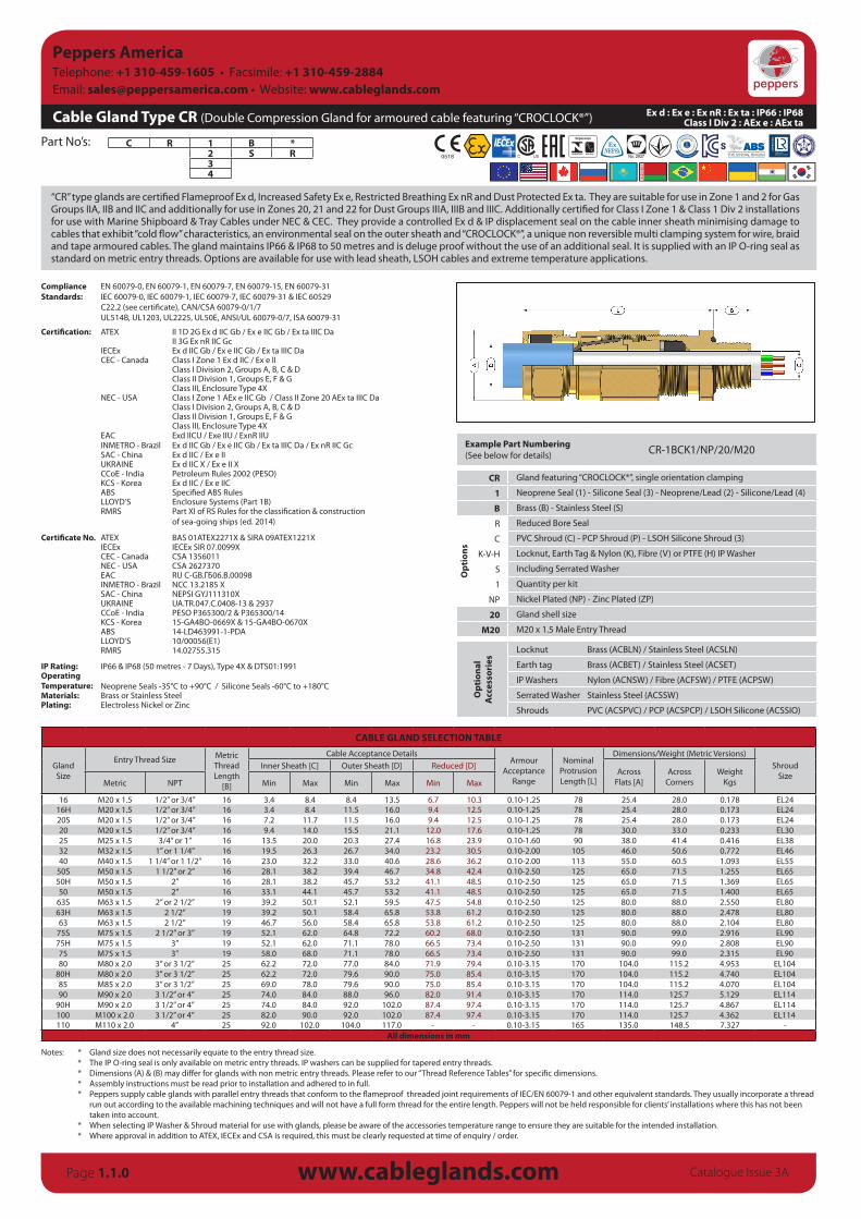
Cable Gland Type CR (Double Compression Gland for armoured cable featuring “CROCLOCK®”)
C R 1 B *2 S R34
Part No’s:
www.cableglands.comPage 1.1.0
“CR” type glands are certified Flameproof Ex d, Increased Safety Ex e, Restricted Breathing Ex nR and Dust Protected Ex ta. They are suitable for use in Zone 1 and 2 for Gas Groups IIA, IIB and IIC and additionally for use in Zones 20, 21 and 22 for Dust Groups IIIA, IIIB and IIIC. Additionally certified for Class I Zone 1 & Class 1 Div 2 installations for use with Marine Shipboard & Tray Cables under NEC & CEC. They provide a controlled Ex d & IP displacement seal on the cable inner sheath minimising damage to cables that exhibit “cold flow” characteristics, an environmental seal on the outer sheath and “CROCLOCK®”, a unique non reversible multi clamping system for wire, braid and tape armoured cables. The gland maintains IP66 & IP68 to 50 metres and is deluge proof without the use of an additional seal. It is supplied with an IP O- ring seal as standard on metric entry threads. Options are available for use with lead sheath, LSOH cables and extreme temperature applications.
ComplianceStandards:
EN 60079-0, EN 60079-1, EN 60079-7, EN 60079-15, EN 60079-31IEC 60079-0, IEC 60079-1, IEC 60079-7, IEC 60079-31 & IEC 60529C22.2 (see certificate), CAN/CSA 60079-0/1/7UL514B, UL1203, UL2225, UL50E, ANSI/UL 60079-0/7, ISA 60079-31
Certification: ATEX II 1D 2G Ex d IIC Gb / Ex e IIC Gb / Ex ta IIIC DaII 3G Ex nR IIC Gc
IECEx Ex d IIC Gb / Ex e IIC Gb / Ex ta IIIC DaCEC - Canada Class I Zone 1 Ex d IIC / Ex e II
Class I Division 2, Groups A, B, C & DClass II Division 1, Groups E, F & GClass III, Enclosure Type 4X
NEC - USA Class I Zone 1 AEx e IIC Gb / Class II Zone 20 AEx ta IIIC DaClass I Division 2, Groups A, B, C & DClass II Division 1, Groups E, F & GClass III, Enclosure Type 4X
EAC Exd IICU / Exe IIU / ExnR IIUINMETRO - Brazil Ex d IIC Gb / Ex e IIC Gb / Ex ta IIIC Da / Ex nR IIC GcSAC - China Ex d IIC / Ex e IIUKRAINE Ex d IIC X / Ex e II XCCoE - India Petroleum Rules 2002 (PESO)KCS - Korea Ex d IIC / Ex e IICABS Specified ABS RulesLLOYD’S Enclosure Systems (Part 1B)RMRS Part XI of RS Rules for the classification & construction
of sea-going ships (ed. 2014)
Certificate No. ATEX BAS 01ATEX2271X & SIRA 09ATEX1221XIECEx IECEx SIR 07.0099XCEC - Canada CSA 1356011NEC - USA CSA 2627370EAC RU C-GB.ГБ06.В.00098INMETRO - Brazil NCC 13.2185 XSAC - China NEPSI GYJ111310XUKRAINE UA.TR.047.C.0408-13 & 2937CCoE - India PESO P365300/2 & P365300/14KCS - Korea 15-GA4BO-0669X & 15-GA4BO-0670XABS 14-LD463991-1-PDALLOYD’S 10/00056(E1)RMRS 14.02755.315
IP Rating: IP66 & IP68 (50 metres - 7 Days), Type 4X & DTS01:1991OperatingTemperature: Neoprene Seals -35°C to +90°C / Silicone Seals -60°C to +180°CMaterials: Brass or Stainless SteelPlating: Electroless Nickel or Zinc
Example Part Numbering(See below for details) CR-1BCK1/NP/20/M20
CR Gland featuring “CROCLOCK®”, single orientation clamping
1 Neoprene Seal (1) - Silicone Seal (3) - Neoprene/Lead (2) - Silicone/Lead (4)
B Brass (B) - Stainless Steel (S)
Opt
ions
R Reduced Bore Seal
C PVC Shroud (C) - PCP Shroud (P) - LSOH Silicone Shroud (3)
K-V-H Locknut, Earth Tag & Nylon (K), Fibre (V) or PTFE (H) IP Washer
S Including Serrated Washer
1 Quantity per kit
NP Nickel Plated (NP) - Zinc Plated (ZP)
20 Gland shell size
M20 M20 x 1.5 Male Entry Thread
Opt
iona
l A
cces
sori
es
Locknut Brass (ACBLN) / Stainless Steel (ACSLN)
Earth tag Brass (ACBET) / Stainless Steel (ACSET)
IP Washers Nylon (ACNSW) / Fibre (ACFSW) / PTFE (ACPSW)
Serrated Washer Stainless Steel (ACSSW)
Shrouds PVC (ACSPVC) / PCP (ACSPCP) / LSOH Silicone (ACSSIO)
CABLE GLAND SELECTION TABLE
GlandSize
Entry Thread Size Metric ThreadLength
[B]
Cable Acceptance DetailsArmour
AcceptanceRange
NominalProtrusionLength [L]
Dimensions/Weight (Metric Versions)Shroud
SizeInner Sheath [C] Outer Sheath [D] Reduced [D]
AcrossFlats [A]
AcrossCorners
WeightKgsMetric NPT Min Max Min Max Min Max
16 M20 x 1.5 1/2” or 3/4” 16 3.4 8.4 8.4 13.5 6.7 10.3 0.10-1.25 78 25.4 28.0 0.178 EL2416H M20 x 1.5 1/2” or 3/4” 16 3.4 8.4 11.5 16.0 9.4 12.5 0.10-1.25 78 25.4 28.0 0.173 EL2420S M20 x 1.5 1/2” or 3/4” 16 7.2 11.7 11.5 16.0 9.4 12.5 0.10-1.25 78 25.4 28.0 0.173 EL2420 M20 x 1.5 1/2” or 3/4” 16 9.4 14.0 15.5 21.1 12.0 17.6 0.10-1.25 78 30.0 33.0 0.233 EL3025 M25 x 1.5 3/4” or 1” 16 13.5 20.0 20.3 27.4 16.8 23.9 0.10-1.60 90 38.0 41.4 0.416 EL3832 M32 x 1.5 1” or 1 1/4” 16 19.5 26.3 26.7 34.0 23.2 30.5 0.10-2.00 105 46.0 50.6 0.772 EL4640 M40 x 1.5 1 1/4” or 1 1/2” 16 23.0 32.2 33.0 40.6 28.6 36.2 0.10-2.00 113 55.0 60.5 1.093 EL55
50S M50 x 1.5 1 1/2” or 2” 16 28.1 38.2 39.4 46.7 34.8 42.4 0.10-2.50 125 65.0 71.5 1.255 EL6550H M50 x 1.5 2” 16 28.1 38.2 45.7 53.2 41.1 48.5 0.10-2.50 125 65.0 71.5 1.369 EL6550 M50 x 1.5 2” 16 33.1 44.1 45.7 53.2 41.1 48.5 0.10-2.50 125 65.0 71.5 1.400 EL65
63S M63 x 1.5 2” or 2 1/2” 19 39.2 50.1 52.1 59.5 47.5 54.8 0.10-2.50 125 80.0 88.0 2.550 EL8063H M63 x 1.5 2 1/2” 19 39.2 50.1 58.4 65.8 53.8 61.2 0.10-2.50 125 80.0 88.0 2.478 EL8063 M63 x 1.5 2 1/2” 19 46.7 56.0 58.4 65.8 53.8 61.2 0.10-2.50 125 80.0 88.0 2.104 EL80
75S M75 x 1.5 2 1/2” or 3” 19 52.1 62.0 64.8 72.2 60.2 68.0 0.10-2.50 131 90.0 99.0 2.916 EL9075H M75 x 1.5 3” 19 52.1 62.0 71.1 78.0 66.5 73.4 0.10-2.50 131 90.0 99.0 2.808 EL9075 M75 x 1.5 3” 19 58.0 68.0 71.1 78.0 66.5 73.4 0.10-2.50 131 90.0 99.0 2.315 EL9080 M80 x 2.0 3” or 3 1/2” 25 62.2 72.0 77.0 84.0 71.9 79.4 0.10-3.15 170 104.0 115.2 4.953 EL104
80H M80 x 2.0 3” or 3 1/2” 25 62.2 72.0 79.6 90.0 75.0 85.4 0.10-3.15 170 104.0 115.2 4.740 EL10485 M85 x 2.0 3” or 3 1/2” 25 69.0 78.0 79.6 90.0 75.0 85.4 0.10-3.15 170 104.0 115.2 4.070 EL10490 M90 x 2.0 3 1/2” or 4” 25 74.0 84.0 88.0 96.0 82.0 91.4 0.10-3.15 170 114.0 125.7 5.129 EL114
90H M90 x 2.0 3 1/2” or 4” 25 74.0 84.0 92.0 102.0 87.4 97.4 0.10-3.15 170 114.0 125.7 4.867 EL114100 M100 x 2.0 3 1/2” or 4” 25 82.0 90.0 92.0 102.0 87.4 97.4 0.10-3.15 170 114.0 125.7 4.362 EL114110 M110 x 2.0 4” 25 92.0 102.0 104.0 117.0 - - 0.10-3.15 165 135.0 148.5 7.327 -
All dimensions in mm
Ex d : Ex e : Ex nR : Ex ta : IP66 : IP68Class I Div 2 : AEx e : AEx ta
Catalogue Issue 3A
* Gland size does not necessarily equate to the entry thread size.* The IP O-ring seal is only available on metric entry threads. IP washers can be supplied for tapered entry threads.* Dimensions (A) & (B) may differ for glands with non metric entry threads. Please refer to our “Thread Reference Tables” for specific dimensions.* Assembly instructions must be read prior to installation and adhered to in full.* Peppers supply cable glands with parallel entry threads that conform to the flameproof threaded joint requirements of IEC/EN 60079-1 and other equivalent standards. They usually incorporate a thread
run out according to the available machining techniques and will not have a full form thread for the entire length. Peppers will not be held responsible for clients’ installations where this has not been taken into account.
* When selecting IP Washer & Shroud material for use with glands, please be aware of the accessories temperature range to ensure they are suitable for the intended installation.* Where approval in addition to ATEX, IECEx and CSA is required, this must be clearly requested at time of enquiry / order.
Peppers AmericaTelephone: +1 310-459-1605 • Facsimile: +1 310-459-2884 Email: [email protected] • Website: www.cableglands.com