cable management system - krupps metalkruppsmetal.net/products/kmc-frp-grp-system.pdf · frp/grp...
TRANSCRIPT

Metal Raceway Product Range
Cable Management System

FRP/GRP SYSTEM
33
Log on to www.kruppsmetal.net
FRP/GRP Product Advantages:
Fibre-reinforced plastic (FRP) (also fibre-reinforced polymer) is a composite material made of a polymer matrix reinforced with fibres. The fibres are usually glass, carbon, or aramid, although other fibres such as paper or wood or asbestos have been sometimes used. The polymer is usually an epoxy, vinylester or polyester thermosetting plastic, and phenol formaldehyde resins are still in use. FRPs are commonly used in the aerospace, automotive, marine, and construction industries.
A polymer is generally manufactured by Step-growth polymerization or addition polymerization. When combined with various agents to enhance or in any way alter the material properties of polymers the result is referred to as a plastic. Composite plastics refer to those types of plastics that result from bonding two or more homogeneous materials with different material properties to derive a final product with certain desired material and mechanical properties. Fibre reinforced plastics are a category of composite plastics that specifically use fibre materials to mechanically enhance the strength and elasticity of plastics. The original plastic material without fibre reinforcement is known as the matrix. The matrix is a tough but relatively weak plastic that is reinforced by stronger stiffer reinforcing filaments or fibres. The extent that strength and elasticity are enhanced in a fibre reinforced plastic depends on the mechanical properties of both the fibre and matrix, their volume relative to one another, and the fibre length and orientation within the matrix. Reinforcement of the matrix occurs by definition when the FRP material exhibits increased strength or elasticity relative to the strength and elasticity of the matrix alone.

Log on to www.kruppsmetal.net
34
FRP/GRP SYSTEM
Fibre process
The manufacture of fibre fabric
Reinforcing Fibre is manufactured in both two dimensional and three dimensional orientations
Two Dimensional Fibre Reinforced Polymer are characterized by a laminated structure in which the fibres are only aligned along the plane in x-direction and y-direction of the material. This means that no fibres are aligned in the through thickness or the z-direction, this lack of alignment in the through thickness can create a disadvantage in cost and processing. Costs and labour increase because conventional processing techniques used to fabricate composites, such as wet hand lay-up, autoclave and resin transfer moulding, require a high amount of skilled labour to cut, stack and consolidate into a preformed component.
Three-dimensional Fibre Reinforced Polymer composites are materials with three dimensional fibre structures that incorporate fibres in the x-direction, y-direction and z-direction. The development of three-dimensional orientations arose from industry's need to reduce fabrication costs, to increase through-thickness mechanical properties, and to improve impact damage tolerance; all were problems associated with two dimensional fibre reinforced polymers.The manufacture of fibre preforms
Fibre preforms are how the fibres are manufactured before being bonded to the matrix. Fibre preforms are often manufactured in sheets, continuous mats, or as continuous filaments for spray applications. The four major ways to manufacture the fibre preform is though the textile processing techniques of Weaving, knitting, braiding and stitching.
Weaving can be done in a conventional manner to produce two-dimensional fibres as well in a multilayer weaving that can create three-dimensional fibres. However, multilayer weaving is required to have multiple layers of warp yarns to create fibres in the z- direction creating a few disadvantages in manufacturing,namely the time to set up all the warp yarns on the loom. Therefore most multilayer weaving is currently used to produce relatively narrow width products, or high value products where the cost of the preform production is acceptable. Another one of the main problems facing the use of multilayer woven fabrics is the difficulty in producing a fabric that contains fibres oriented with angles other than 0" and 90" to each other respectively.
The second major way of manufacturing fibre preforms is Braiding. Braiding is suited to the manufacture of narrow width flat or tubular fabric and is not as capable as weaving in the production of large volumes of wide fabrics. Braiding is done over top of mandrels that vary in cross-sectional shape or dimension along their length. Braiding is limited to objects about a brick in size. Unlike the standard weaving process, braiding can produce fabric that contains fibres at 45 degrees angles to one another. Braiding three-dimensional fibres can be done using four step, two-step or Multilayer Interlock Braiding.Four step or row and column braiding utilizes a flat bed containing rows and columns of yarn carriers that form the shape of the desired preform. Additional carriers are added to the outside of the array, the precise location and quantity of which depends upon the exact preform shape and structure required. There are four separate sequences of row and column motion, which act to interlock the yarns and produce the braided preform. The yarns are mechanically forced into the structure between each step to consolidate the structure in a similar process to the use of a reed in weaving.Two-step braiding is unlike the four step process because the two-step includes a large number of yarns fixed in the axial direction and a fewer number of braiding yarns. The process consists of two steps in which the braiding carriers move completely through the structure between the axial carriers. This relatively simple sequence of motions is capable of forming preforms of essentially any shape, including circular and hollow shapes. Unlike the four step process the two step process does not require mechanical compaction the motions involved in the process allows the braid to be pulled tight by yarn tension alone. The last type of braiding is multi-layer interlocking braiding that consists of a number of standard circular braiders being joined together to form a cylindrical braiding frame. This frame has a number of parallel braiding tracks around the circumference of the cylinder but the mechanism allows the transfer of yarn carriers between adjacent tracks forming a multilayer braided fabric with yarns interlocking to adjacent layers. The multilayer interlock braid differs from both the four step and two-step braids in that the interlocking yarns are primarily in the plane of the structure and thus do not significantly reduce the in-plane properties of the preform. The four step and two step processes produce a greater degree of
FRP/GRP SYSTEM
35
Log on to www.kruppsmetal.net
interlinking as the braiding yarns travel through the thickness of the preform, but therefore contribute less to the in-plane performance of the preform. A disadvantage of the multilayer interlock equipment is that due to the conventional sinusoidal movement of the yarn carriers to form the preform, the equipment is not able to have the density of yarn carriers that is possible with the two step and four step machines.
Knitting fibre preforms can be done with the traditional methods of Warp and [Weft] Knitting, and the fabric produced is often regarded by many as two-dimensional fabric, but machines with two or more needle beds are capable of producing multilayer fabrics with yams that traverse between the layers. Developments in electronic controls for needle selection and knit loop transfer, and in the sophisticated mechanisms that allow specific areas of the fabric to be held and their movement controlled. This has allowed the fabric to form itself into the required three-dimensional preform shape with a minimum of material wastage.
Stitching is arguably the simplest of the four main textile manufacturing techniques and one that can be performed with the smallest investment in specialized machinery. Basically the stitching process consists of inserting a needle, carrying the stitch thread, through a stack of fabric layers to form a 3D structure. The advantages of stitching are that it is possible to stitch both dry and prepreg fabric, although the tackiness of the prepreg makes the process difficult and generally creates more damage within the prepreg material than in the dry fabric. Stitching also utilizes the standard two-dimensional fabrics that are commonly in use within the composite industry therefore there is a sense of familiarity concerning the material systems. The use of standard fabric also allows a greater degree of flexibility in the fabric lay-up of the component than is possible with the other textile processes, which have restrictions on the fibre orientations that can be produced.
Moulding processes
There are two distinct categories of moulding processes using FRP plastics; this includes composite moulding and wet moulding. Composite moulding uses Prepreg FRP, meaning the plastics are fibre reinforced before being put through further moulding processes. Sheets of Prepreg FRP are heated or compressed in different ways to create geometric shapes. Wet moulding combines fibre reinforcement and the matrix or resist during the moulding process. The different forms of composite and wet moulding, are listed below.
Composite moulding
Bladder moulding
Individual sheets of prepreg material are laid -up and placed in a female-style mould along with a balloon-like bladder. The mould is closed and placed in a heated press. Finally, the bladder is pressurized forcing the layers of material against the mould walls. The part is cured and removed from the hot mould. Bladder moulding is a closed moulding process with a relatively short cure cycle between 15 and 60 minutes making it ideal for making complex hollow geometric shapes at competitive costs.
Compression moulding
A "preform" or "charge", of SMC, BMC or sometimes prepreg fabric, is placed into mould cavity. The mould is closed and the material is compacted & cured inside by pressure and heat. Compression moulding offers excellent detailing for geometric shapes ranging from pattern and relief detailing to complex curves and creative forms, to precision engineering all within a maximum curing time of 20 minutes.
Autoclave / vacuum bag
Individual sheets of prepreg material are laid-up and placed in an open mold. The material is covered with release film, bleeder/breather material and a vacuum bag. A vacuum is pulled on part and the entire mould is placed into an autoclave (heated pressure vessel). The part is cured with a continuous vacuum to extract entrapped gasses from laminate. This is a very common process in the aerospace industry because it affords precise control over the moulding process due to a long slow cure cycle that is anywhere from one to two hours. This precise control creates the exact laminate geometric forms needed to ensure strength and safety in the aerospace industry, but it is also slow and labour intensive, meaning costs often confine it to the aerospace industry.

Log on to www.kruppsmetal.net
36
FRP/GRP SYSTEM
Mandrel wrapping
Sheets of prepreg material are wrapped around a steel or aluminium mandrel. The prepreg material is compacted by nylon or polypropylene cello tape. Parts are typically batch cured by hanging in an oven. After cure the cello and mandrel are removed leaving a hollow carbon tube. This process creates strong and robust hollow carbon tubes.
Wet layup
Fibre reinforcing fabric is placed in an open mould and then saturated with a wet [resin] by pouring it over the fabric and working it into the fabric and mould. The mould is then left so that the resin will cure, usually at room temperature, though heat is sometimes used to ensure a proper curing process. Glass fibres are most commonly used for this process, the results are widely known as fibreglass, and is used to make common products like skis, canoes, kayaks and surf boards.
Chopper gun
Continuous strand of fibreglass are pushed through a hand-held gun that both chops the strands and combines them with a catalysed resin such as polyester. The impregnated chopped glass is shot onto the mould surface in whatever thickness the design and human operator think is appropriate. This process is good for large production runs at economical cost, but produces geometric shapes with less strength than other moulding processes and has poor dimensional tolerance.
Filament winding
Machines pull fibre bundles through a wet bath of resin and wound over a rotating steel mandrel in specific orientations Parts are cured either room temperature or elevated temperatures. Mandrel is extracted, leaving a final geometric shape but can be left in some cases.
Pultrusion
Fibre bundles and slit fabrics are pulled through a wet bath of resin and formed into the rough part shape. Saturated material is extruded from a heated closed die curing while being continuously pulled through die. Some of the end products of the pultrusion process are structural shapes, i.e. I beam, angle, channel and flat sheet. These materials can be used to create all sorts of fibreglass structures such as ladders, platforms, handrail systems tank, pipe and pump supports.
RTM & VARTM
Also called resin infusion. Fabrics are placed into a mould which wet resin is then injected into. Resin is typically pressurized and forced into a cavity which is under vacuum in the RTM (Resin Transfer Molding) process. Resin is entirely pulled into cavity under vacuum in the VARTM (Vacuum Assisted Resin Transfer Molding) process. This moulding process allows precise tolerances and detailed shaping but can sometimes fail to fully saturate the fabric leading to weak spots in the final shape.
Advantages and limitations
FRP allows the alignment of the glass fibres of thermoplastics to suit specific design programs. Specifying the orientation of reinforcing fibres can increase the strength and resistance to deformation of the polymer. Glass reinforced polymers are strongest and most resistive to deforming forces when the polymers fibres are parallel to the force being exerted, and are weakest when the fibres are perpendicular. Thus this ability is at once both an advantage or a limitation depending on the context of use. Weak spots of perpendicular fibres can be used for natural hinges and connections, but can also lead to material failure when production processes fail to properly orient the fibres parallel to expected forces. When forces are exerted perpendicular to the orientation of fibres the strength and elasticity of the polymer is less than the matrix alone. In cast resin components made of glass reinforced polymers such as UP and EP, the orientation of fibres can be oriented in two-dimensional and three-dimensional weaves. This means that when forces are possibly perpendicular to one orientation, they are parallel to another orientation; this eliminates the potential for weak spots in the polymer.

FRP/GRP SYSTEM
37
Log on to www.kruppsmetal.net
Failure modes
Structural failure can occur in FRP materials when:
Tensile forces stretch the matrix more than the fibres, causing the material to shear at the interface between matrix and fibres. Tensile forces near the end of the fibres exceed the tolerances of the matrix, separating the fibres from the matrix. Tensile forces can also exceed the tolerances of the fibres causing the fibres themselves to fracture leading to material failure.
Material requirements
The matrix must also meet certain requirements in order to first be suitable for the FRP process and ensure a successful reinforcement of itself. The matrix must be able to properly saturate, and bond with the fibres within a suitable curing period. The matrix should preferably bond chemically with the fibre reinforcement for maximum adhesion. The matrix must also completely envelope the fibres to protect them from cuts and notches that would reduce their strength, and to transfer forces to the fibres. The fibres must also be kept separate from each other so that if failure occurs it is localized as much as possible, and if failure occurs the matrix must also debond from the fibre for similar reasons. Finally the matrix should be of a plastic that remains chemically and physically stable during and after reinforcement and moulding processes. To be suitable for reinforcement material fibre additives must increase the tensile strength and modulus of elasticity of the matrix and meet the following conditions; fibres must exceed critical fibre content; the strength and rigidity of fibres itself must exceed the strength and rigidity of the matrix alone; and there must be optimum bonding between fibres and matrix
Glass fibre material
Further information: Glass-reinforced plastic glam resinforced polyester FRPs use textile glass fibres; textile fibres are different from other forms of glass fibres used for insulating applications. Textile glass fibres begin as varying combinations of SiO2, Al2O3, B2O3, CaO, or MgO in powder form. These mixtures are then heated through a direct melt process to temperatures around 1300 degrees Celsius, after which dies are used to extrude filaments of glass fibre in diameter ranging from 9 to 17 µm. These filaments are then wound into larger threads and spun onto bobbins for transportation and further processing. Glass fibre is by far the most popular means to reinforce plastic and thus enjoys a wealth of production processes, some of which are applicable to aramid and carbon fibres as well owing to their shared fibrous qualities.
Roving is a process where filaments are spun into larger diameter threads. These threads are then commonly used for woven reinforcing glass fabrics and mats, and in spray applications. Fibre fabrics are web-form fabric reinforcing material that has both warp and weft directions. Fibre mats are web-form non-woven mats of glass fibres. Mats are manufactured in cut dimensions with chopped fibres, or in continuous mats using continuous fibres. Chopped fibre glass is used in processes where lengths of glass threads are cut between 3 and 26 mm, threads are then used in plastics most commonly intended for moulding processes. Glass fibre short strands are short 0.2–0.3 mm strands of glass fibres that are used to reinforce thermoplastics most commonly for injection moulding.
Unlike glass fibers used for insulation, for the final structure to be strong, the fiber's surfaces must be almost entirely free of defects, as this permits the fibers to reach gigapascal tensile strengths. If a bulk piece of glass were to be defect free, then it would be equally as strong as glass fibers; however, it is generally impractical to produce bulk material in a defect-free state outside of laboratory conditions.
Production
The manufacturing process for glass fibers suitable for reinforcement uses large furnaces to gradually melt the silica sand, limestone, kaolin clay, fluorspar, colemanite, dolomite and other minerals to liquid form. Then it is extruded through bushings, which are bundles of very small orifices (typically 5–25 micrometres in diameter for E-Glass, 9 micrometres for S-Glass). These filaments are then sized (coated) with a chemical solution. The individual filaments are now bundled together in large numbers to provide a roving. The diameter of the filaments, as well as the number of filaments in the roving determine its weight. This is typically expressed in yield-yards per pound (how many yards of fiber in one pound of material, thus a smaller number means a heavier roving, example of standard yields are 225yield, 450yield, 675yield) or in tex-grams per km (how many grams 1 km of roving weighs, this is inverted from yield, thus a smaller number means a lighter roving, examples of standard tex are 750 tex, 1100 tex, 2200 tex).

Log on to www.kruppsmetal.net
38
FRP/GRP SYSTEM
These rovings are then either used directly in a composite application such as pultrusion, filament winding (pipe), gun roving (automated gun chops the glass into short lengths and drops it into a jet of resin, projected onto the surface of a mold), or used in an intermediary step, to manufacture fabrics such as chopped strand mat (CSM) (made of randomly oriented small cut lengths of fiber all bonded together), woven fabrics, knit fabrics or uni-directional fabrics.
Sizing
A sort of coating, or primer, is used which both helps protect the glass filaments for processing/manipulation as well as ensure proper bonding to the resin matrix, thus allowing for transfer of shear loads from the glass fibers to the thermoset plastic. Without this bonding, the fibers can 'slip' in the matrix and localised failure would ensue.
Properties
An individual structural glass fiber is both stiff and strong in tension and compression—that is, along its axis. Although it might be assumed that the fiber is weak in compression, it is actually only the long aspect ratio of the fiber which makes it seem so; i.e., because a typical fiber is long and narrow, it buckles easily. On the other hand, the glass fiber is weak in shear—that is, across its axis. Therefore if a collection of fibers can be arranged permanently in a preferred direction within a material, and if the fibers can be prevented from buckling in compression, then that material will become preferentially strong in that direction.
Furthermore, by laying multiple layers of fiber on top of one another, with each layer oriented in various preferred directions, the stiffness and strength properties of the overall material can be controlled in an efficient manner. In the case of fiberglass, it is the plastic matrix which permanently constrains the structural glass fibers to directions chosen by the designer. With chopped strand mat, this directionality is essentially an entire two dimensional plane; with woven fabrics or unidirectional layers, directionality of stiffness and strength can be more precisely controlled within the plane.
A fiberglass component is typically of a thin "shell" construction, sometimes filled on the inside with structural foam, as in the case of surfboards. The component may be of nearly arbitrary shape, limited only by the complexity and tolerances of the mold used for manufacturing the shell.
Applications
Fiberglass is an immensely versatile material which combines its light weight with an inherent strength to provide a weather resistant finish, with a variety of surface textures.
The development of fiber reinforced plastic for commercial use was being extensively researched in the 1930s. It was particularly of interest to the aviation industry. Mass production of glass strands was accidentally discovered in 1932 when a researcher at the Owens-Illinois accidentally directed a jet of compressed air at a stream of molten glass and produced fibers. Owens joined up with the Corning company in 1935 and the method was adapted by Owens Corning to produce its patented "Fiberglas" (one "s"). A suitable resin for combining the "Fiberglas" with a plastic was developed in 1936 by du Pont. The first ancestor of modern polyester resins is Cyanamid's of 1942. Peroxide curing systems were used by then.
Polyester resin (Not reinforced)[4] 1.28 55 (7.98) 140 (20.3)
Polyester and Chopped Strand Mat Laminate 30% E-glass[4] 1.4 100 (14.5) 150 (21.8)
Polyester and Woven Rovings Laminate 45% E-glass[4] 1.6 250 (36.3) 150 (21.8)
Polyester and Satin Weave Cloth Laminate 55% E-glass[4] 1.7 300 (43.5) 250 (36.3)
Polyester and Continuous Rovings Laminate 70% E-glass[4] 1.9 800 (116) 350 (50.8)
E-Glass Epoxy composite[5] 1.99 1,770 (257)
S-Glass Epoxy composite[5] 1.95 2,358 (342)
Material Specific gravity Tensile strength MPa (ksi) Compressive strength MPa (ksi)

FRP/GRP SYSTEM
39
Log on to www.kruppsmetal.net
During World War II it was developed as a replacement for the molded plywood used in aircraft radomes (fiberglass being transparent to microwaves). Its first main civilian application was for building of boats and sports car bodies, where it gained acceptance in the 1950s. Its use has broadened to the automotive and sport equipment sectors as well as aircraft, although its use there is now partly being taken over by carbon fiber which weighs less per given volume and is stronger both by volume and by weight. Fiberglass uses also include hot tubs, pipes for drinking water and sewers, office plant display containers and flat roof systems.
Advanced manufacturing techniques such as pre-pregs and fiber rovings extend the applications and the tensile strength possible with fiber-reinforced plastics.
Fiberglass is also used in the telecommunications industry for shrouding the visual appearance of antennas, due to its RF permeability and low signal attenuation properties. It may also be used to shroud the visual appearance of other equipment where no signal permeability is required, such as equipment cabinets and steel support structures, due to the ease with which it can be molded, manufactured and painted to custom designs, to blend in with existing structures or brickwork. Other uses include sheet form made electrical insulators and other structural components commonly found in the power industries.
Because of fiberglass' light weight and durability, it is often used in protective equipment, such as helmets. Many sports utilize fiberglass protective gear, such as modern goaltender masks and newer baseball catcher's masks. Pultrusion operation
Diagram of the pultrusion process.
Pultrusion is a manufacturing method used to make strong light weight composite materials, in this case fiberglass. Fibers (the glass material) are pulled from spools through a device that coats them with a resin. They are then typically heat treated and cut to length. Pultrusions can be made in a variety of shapes or cross-sections such as a W or S cross-section. The word pultrusion describes the method of moving the fibers through the machinery. It is pulled through using either a hand over hand method or a continuous roller method. This is opposed to an extrusion, which would push the material through dies.
The pultrution processoverviewRoving
Resin bath
Continuous matsand surface veil
Pre-molding and finish-molding
Pulling
Cutting
Process controleHeated
die

Log on to www.kruppsmetal.net
40
FRP/GRP SYSTEM
Ultimate Tensile Strength, PSI (ASTM D638) 30,000 35,000Ultimate Compressive Strength, PSI (ASTM D695) 30,000 35,000Ultimate Flexural Strength, PSI (ASTM D790) 30,000 35,000Tensile Modulus, PSI x 106 2.5 3.0Compressive Modulus, PSI x 106 2.5 2.5Flexural Modulus, PSI x 106 1.6 2.0Ultimate Shear Strength, PSI 5,500 7,000Ultimate Bearing Stress, PSI 30,000 35,000Izod Impact Strength, Ft.-Lbs. per inch of notch(ASTM D256) (sample thickness 1/8” 25 30except 1/4” for rod)
Typical Properties of Structural FRP
Longitudinal Direction Transverse Direction
Mechanical (coupon) FR-P FR-VE
Ultimate Tensile Strength, PSI 7,000 10,000Ultimate Compressive Strength, PSI 15,000 20,000Ultimate Flexural Strength, PSI 10,000 14,000Tensile Modulus, PSI x 106 0.8 1.0Compressive Modulus, PSI x 106 1.0 1.2Flexural Modulus, PSI x 106 0.8 1.0Ultimate Shear Strength, PSI 5,500 6,000Ultimate Bearing Stress, PSI 30,000 35,000Izod Impact Strength, Ft.-Lbs. perinch of notch (ASTM D256) 4 5Barcol Hardness (ASTM D2583-75 50 50
Mechanical (coupon) FR-P FR-VE
Full Section in Bending
Electric Strength, short term in oil, 1�8”, vpm(ASTM D149)* 200 200Electric Strength, short term in oil, KV per inch 35 35Dissipation Factor, 60 Hz. (ASTM D150)* 0.03 0.03Dielectric Constant, 60 Hz.(ASTM D150)* 5.6 5.2Arc Resistance, seconds (ASTM D495)** 120 20
Electrical
Mechanical (coupon) FR-P FR-VE
Flame Resistance, ign/burn, seconds(FTMS 406-2023) 75/75 75/75Intermittent Flame Test, rating (HLT-15) 100 100Flammability Testaverage time of burning 5seconds, average extent ofburning 15mm (ASTM D635)Surface Burning Characteristics, maximum 15 15(ASTM E84)
Note: 1 PSI = 6.894 K Pa; 1 Ft.-Lb./In. = 5.443 kg-m/m; * Specimen tested perpendicular to laminate face ** Indicates reported value measured in logitudinal direction; Depending on the specific glasscontent and resin, the strength and stiffness properties may be significantly higher. Contact us for specific values on Halogen-Free Low Smoke Plus resin properties.
Fire Retardant Properties
Mechanical (coupon) FR-P FR-VE
Modulus of Elasticity, PSI x 106 2.5 3.0Tensile Strength, PSI 20,000 25,000Compressive Strength, PSI 20,000 25,000
Mechanical (coupon) FR-P FR-VE
Thermal
Thermal Coefficient of ExpansionInches/Inch/°F (ASTM D696)** 5 x 10⁻⁶ 5 x 10⁻⁶
Thermal Conductivity, BTU perSq. Ft./Ht./°F/In. (ASTM C-177-76) 4 4Specific Heat, BTU/Lb./°F 0.28 0.28
Mechanical (coupon) FR-P FR-VE
Other
Density, Lbs./In.3 (ASTM D792 0.065 0.065Specific Gravity (ASTM D792) 1.80 1.80Water Absorption, Max. % by weight(24 hour immersion) (ASTM D570) .50 .50
Mechanical (coupon) FR-P FR-VE
Chopped strand mat
Chopped strand mat or CSM is a form of reinforcement used in fiberglass. It consists of glass-fibers laid randomly across each other and held together by a binder.
It is typically processed using the hand lay-up technique, where sheets of material are placed in a mold and brushed with resin. Because the binder dissolves in resin, the material easily conforms to different shapes when wetted out. After the resin cures, the hardened product can be taken from the mold and finished.
Using chopped strand mat gives a fiberglass with isotropic in-plane material properties

FRP/GRP SYSTEM
41
Log on to www.kruppsmetal.net
25°F (-4°C) 417 (126) 320 (97) 162 (49)50°F (10°C) 208 (63) 160 (48) 81 (25)75°F (24°C) 138 (42) 106 (32) 54 (16)100°F (38°C) 104 (32) 80 (24) 40 (12)125°F (52°C) 83 (25) 63 (19) 32 (10)150°F (66°C) 69 (21) 53 (16) 26 (8)175°F (79°C) 59 (17) 45 (13) 23 (6)
Concentric Static Load (if required)
A concentrated static load is not included in the table on page 9. Some user applications may require that a given concentrated static load be imposed over and above the working load. Such concentrated static load represents a static weight applied between the side rail at midspan. When so speci� ed, the concentrated static load may be converted to an equivalent load (We) in pounds per linear foot (kg/m) using the formula to the below right and added to the static weight of cable in the tray. This combined load may be used to select a suitable load/span designation).
If the combined load exceeds the working load shown, please cont us.This data was obtained from the NEMA Standards Publication and other sources to assist inthe proper selection of the most appropriate cable tray type offered by Enduor.
Effect fo Temperature - FRP
Strength properties of reinforced plastics are reduced when continuously exposed to elevated temperatures. Working loads shall be reduced when based on the table to the right. Percentages shown are approximate. If unusual temperature conditions exist, please contact us for consultation. Below freezing temperatures do not adversely affect the load rating capability of the tray. Fiberglass does not become brittle at below freezing temperatures. Careful review should be made of applica-tions involving service temperatures over 200°F.
Thermal Contraction & Expansion Fiberglass vs Steel vs Aluminum
We
=2 x (Concentrated Static Load)
span length (ft or m)
The table to the right compares the thermal contraction and expansion based on various temperature differentials for berglass, steel and aluminum cable trays. The values shown represent the length of cable tray that will produce a 5�8” movement between expansion connectors for the indicated temperature differential. Fiberglass has the least movement. Enduro has expansion connectors to provide for total movement of 5�8”.
Temp. Fiberglass Steel AluminumDifferential Ft. (m) Ft. (m) Ft. (m)
75°F (24°C) 100% 100%100˚F (38˚C) 90% 100%125°F (52°C) 78% 100%150°F (66°C) 68% 90%175°F (79°C) 60% 90%200°F (93°C) 52% 75%
Temp. Polyester Vinyl Easter Stength % Strength %
Test Temp. ˚F (˚C) -100˚ -50˚ -0˚ -50˚ -77˚ 100˚ 150˚ 200˚ 250˚ 300˚ (-73˚) (-46˚) (-18˚) (-10˚) (25˚) (38˚) (66˚) (93˚) (121˚) (149˚)
Flex. St., PSI, ASTM D790 101,500 86,400 79,500 72,300 68,100 66,300 58,700 27,400 13,200 9,200Flex. Mod., PSI x 106, ASTM D790 3.36 3.32 3.42 3.38 3.24 3.29 3.07 1.98 0.98 0.83Tensile St., PSI, ASTM D638 84,100 70,400 63,900 58,000 56,100 54,600 49,900 41,800 29,600 22,000
Corrosion Resistance of Resin Systems
Hdmann has two standard resin systems available. For most applications, isophthalic polyester fire-retardant (FR-P) is the more widely used. A vinyl ester composite � re-retardant resin system (FR-VE) is recommended where strong acids (such as hydrochloric acid), strong alkalies (such as caustic soda), organic solvents and halogenated organic conditions exist. An abbreviated guide is provided below to assist in the selection of the proper resin system for individual application.
Polyester and vinyl ester resin systems are available in conductive formulation. Contact us for corrosion resistance information for halogen-free and halogen-free low smoke plus resins.
All composite materials have an ultra-violet light inhibiting chemical additive and has a maximum � ame spread of 25 or less, per ASTM E-84 (Class 1 ame spread). All pultruded products have complete Nexus Veil Coverage (outer surfacing fabric) to provide maximum chemical and UV protection.

Log on to www.kruppsmetal.net
42
FRP/GRP SYSTEM
Chemicals 75˚F (24˚C) 160F˚ (71˚C) Chemicals 75˚F (24˚C) 160F˚ (71˚C)
Acetic Acid 5% FR-P FR-P Magnesium Chloride FR-P FR-PAcetic Acid 25% FR-P FR-VE-210° (*) Methyl Alcohol 10% FR-P FR-VE-150° (*)Aluminum Potassium Sulfate 5% FR-P FR-P Naphtha FR-P FR-PAmmonium Hydroxide 10% FR-P FR-VE-150° Nitric Acid 5% FR-P FR-PAmmonium Nitrate FR-P FR-P Nitric Acid 20% FR-VE FR-VE-120° (*)Benzenesulfonic Acid 5% FR-P FR-P Phosphoric Acid 10% FR-P FR-PEthylene Glycol FR-P FR-P Sodium Hypochlorite 5% FR-P FR-VE-120° (*)Carbon Tetrachloride FR-VE FR-VE-100° (*) Phosphoric Acid 85% FR-P FR-PChlorine Dioxide 15% FR-P FR-VE-150° (*) Sodium Bicarbonate 10% FR-P FR-PChromic Acid 5% FR-P FR-VE-150° (*call) Sodium Bisulfate FR-P FR-PCopper Sulfate FR-P FR-P Sodium Carbonate FR-P FR-VEDiesel Fuel No. 1 FR-P FR-P Sodium Chloride FR-P FR-PDiesel Fuel No. 2 FR-P FR-P Sodium Hydroxide 1-50% FR-VE FR-VE-120° (*)Ferrous Sulfate FR-P FR-P Sodium Silicate FR-P FR-VE-210° (*)Fatty Acids 100% FR-P FR-P Sodium Nitrate FR-P FR-PFluosilicic Acid 0-20% FR-VE FR-VE (call) Sodium Sulfate FR-P FR-PHydrochloric Acid 1% FR-P FR-P Sulfuric Acid 0-30% FR-P FR-PHydrochloric Acid 15% FR-P FR-VE-180° (*) Sulfuric Acid 30-50% FR-VE FR-VEHydrochloric Acid 37% FR-P FR-VE-150° (*) Sulfuric Acid 50-70% FR-VE FR-VE-180° (*)Hydrogen Sulfide FR-P-140° FR-VE-210° Trisodium Phosphate 25% FR-P FR-VE-210° (*)Kerosene FR-P FR-P Trisodium Phosphate - All FR-VE FR-VE-210° (*) Water, Distilled FR-P FR-P
FR = Fire-Retardant; P = Polyester Resin; VE = Vinyl Ester Resin; (*) = Not recommended to exceed this temperature; call = Call for recommendations Information contained in this chart is based on data from raw material suppliers and collected from several years of actual industrial applications. Temperaturers are not the minimum nor the maximum (except where speci� cally stated) but represent standard test conditions. The products may be suitable at higher temperatures, but individual test data should be required to establish such suitability. The recommen-dations or suggestions contained in this chart are made without guarantee or representation as to results. We suggest that you evaluate these recommendations and suggestions in your own laboratory or by actual � eld trial prior to use
Resin Systems
Below is an overview of the common resin systems we offer. When choosing a resin type for your application, we highly recom-mend consulting with us regarding the application to be sure the proper resin is specif i ed. Considerations include corrosion environment, temperature, f ire resistance, smoke and smoke toxicity requirements and conductivity / resistivity requirements. Regarding the corrosion environment, certain chemical concentrations and temperatures will dictate whether a polyester or epoxy vinyl ester system is preferred for optimum durability.
IsophthalicPolyester
(P)
(V)
(C)
(HP)
(HV)
(HS)
This industrial-grade polyester resin system offers very good weathering performance (resistance to UV) and corrosion resistance. This system is especially suitable for seawater environments.
Vinyl Ester This resin system also delivers good weathering performance, but is superior to a polyester with respect to corrosion resistance and high heat environments. Epoxy vinyl ester resins provide greater toughness and considerably higher strength at elevated temperatures. They also provide superior resistance to chemical attack in corrosive chemical service.
Conductive This Isophthalic Polyester-based resin is formulated to comply with ABS requirements for conduc-tivity. To provide superior resistance to chemical attack, the conductive formulation is also available in a Vinyl Ester base.
Halogen-FreePolyester
This system offers similar performance attributes as our standard Isophthalic Polyester, but without the use of halogens.
Halogen-FreeVinyl Ester
This system offers similar performance attributes as our Vinyl Ester, but without the use of halogens.
Halogen-FreeLow Smoke Plus
This modified-acrylic based resin is suitable for applications which require extremely low-smoke development in the case of fre. This resin system is commonly used in tunnel applications.

Log on to www.kruppsmetal.net
43
FRP/GRP SYSTEM
Support Location Guidelines*
Correct
Incorrect
Installation
The installation of Kruppsmetal Cable Tray / Ladder / Trunking-should be made in compliance with the standards set forth by the National Electric Code and NEMA Publications FG-1 (current issue). Enduro supplies made to order, pre-fabricated cable ladder tray and f i ttings as specif i ed by the purchaser.
Always observe common safety practices when assembling tray and f i ttings in the f i eld. Assemble in wellventilated areas as dust from f i eld cuts can accumulate. This presents no serious health hazard but can cause skin irritation and, if allowed to accumulate with grease and other machining lubricants, can become abrasive. Personnel should wear safety goggles, dust mask, coveralls or a shop coat when sawing, machining and/or sanding. Caution should also be noted when cutting as dust from carbon f i ber is also electrically conductive and additional considerations apply.
Avoid generating excessive heat in any machining operation,as heat softens the bonding resin in the f i berglass, resulting in a ragged rather than a clean-cut edge.Avoid excessive pressure when sawing, drilling, routing, etc. Use carbide-tipped drill bits and saw blades for extended tool life. The use of lubricant during machining is not recom-mended.To avoid chipping of material at cut edges, secure cable tray and f i ttings properly during f i eld cut operations. We recom-mend the use of Enduro sealant for sealing surfaces and cut edges after f i eld cuts are made. When using adhesives, be sure to prepare the surface properly before applying. Follow label instructions carefully. A combination of mechanical fasteners and adhesives make the strongest most reliable connections.
* These guidelines apply when using standard splice plates. For location flexibility, heavy duty splice plates allow for support location anywhere in the span.
WARNING! CABLE TRAYS ARE NOT DESIGNED FOR USE AS WALKWAYS
Reference NEMA FG-1 (current issue)In as much as fiberglass cable tray is designed as a support for power or control cables, or both; it is not intended or designed to be a walkway for personnel. The user is urged to display appropriate warning cautioning against the use of this support as a walkway.
Actual Size Label
WARNING!Do not use a walkway, Ladder or
Support for Personnel.
Use only as a Mechanical Supportfor cables, Tubing and Raceways.

External Bend 90˚
Internal Bend 90˚
Flat Cover
HorizontalBend 45˚
HoldDown Clamp
HorizontalRadius Tee
Push ButtonSupport StandChannel Type
Tray Fitting
Drop Out
InstrumentSupport Stands
45˚ HorizontalRadius Bend
Blind End
Straight Sections
Outside VerticalAdjustable
Radius Bend
Divider Strip
Right HandReducer
30° JoiningVertical Bends
Splice Plate
HorizontalRadius Cross
Lay-In Wirewaywith Cover
Peaked VentilatedCover
ExpansionSplice Plate
FRP/GRP LADDER
44
Log on to www.kruppsmetal.net

LR SR
SLRSTR
1 = 150m2 = 200m3 = 250m4 = 300m5 = 400m6 = 450m
Rung Space
Log on to www.kruppsmetal.net
45
FRP/GRP LADDER
KLP3 - C - 6 - 4 - P - SR - 4 - O - 3
CABLE LADDER SELECTION CHART
NemaClass
Profile Bottom
C
K
I
10 = 100m15 = 150m20 = 200m22 = 225m25 = 250m30 = 300m35 = 350m40 = 400m45 = 450m50 = 500m60 = 600m75 = 750m90 = 900m
KLP3KTP4KHP4KTP6KLP6KHP6D-KHP6KHZ6KHP8D-KHP10
Width
2 = 50m3 = 75m4 = 100m5 = 125m6 = 150m
Side Rail
Resin
Rung Style
3=3mtr6 = 6mtr
LengthO = OpenS = Solid Bottom
SR = Strut RungSLR = Strut Slotted RungSTR = Solid Tube RungLR = Light Rung
P = Polyester ResinV = Vinyl EsterH = Hologen Free PolyesterHL = Hologen Free Low SmokeHVS = Hologen Free Vinyl EsterRT = Conductive
1” (25mm)
14” (6mm)
LOA
DIN
G D
EPTH
SID
E R
AIL
HEI
GH
T
FLANGE WIDTH
Side Rail
1” (25mm)
14” (6mm)
LOA
DIN
G D
EPTH
SID
E R
AIL
HEI
GH
T
FLANGE WIDTH KHZ6
1” (25mm)
14” (6mm)
LOA
DIN
G D
EPTH
SID
E R
AIL
HEI
GH
T
FLANGE WIDTH KHZ6KLP3 KHP6KTP4 D-KHP6KHP4 KHP8KTP6 D-KHP10KLP6

FRP/GRP TECHNICAL DETAIL
KLP3 KL(∆)3 3” 1-13/16” 1” 3/16” (75) (46) (25) (4.8) 8A 1.5 -
KTP4 KT(∆)4 4” 2-7/8” 1-3/8” 1/4” (100) (73) (35) (6.4) 8A 1.5 -
KHP4 KH(∆)4 4” 2-3/4” 1-1/8” 1/4” (100) (70) (28) (6.4) 12A 1.5 Class A
KTP6 KT(∆)6 6” 4-13/16” 1-5/8” 5/32” (150) (122) (41) (4.0) 18A 1.5 -
KLP6 KL(∆)6 6” 4-13/16” 1-5/8” 3/16” (150) (122) (41) (4.8) 20A 2.0 Class A
KHP6 KH(∆)6 6” 4-3/4 1-5/8” 1/4” 20B 2.0 (150) (121) (41) (6.4) 20A 2.0 Class C
D-KHP6 D-KH(∆)6 6” 4-11/16” 1-5/8” 5/16” (150) (119) (41) (8.0) 20C 2.0 Class C
KHZ6 KHZ(∆)6 6” 4-11/16” 2” 5/16” (150) (119) (51) (8.0) 20C 2.0 -
KHP8 KH(∆)8 8” 6-11/16” 1-3/4” 5/16” (200) (170) (44) (8.0) 20C 1.5 Class C
D-KHP10 D-KH(∆)10 10” 8-5/8” 2-3/4” 3/8” (250) (219) (70) (9.5) 30C 2.0 -
NEMAClass(Polyester resin)
OptionalSystem No.(∆) = insert code;see bottom of pg.
Side RailHeightIn. (mm)
Loading DepthIn. (mm)
Flange WidthIn. (mm)
Min. Channel ThicknessIn. (mm)
NEMAClassFG-1
SafetyFactor
Ladder Cable Tray Selection Guide
(∆) = Insert one of the following letters for resign designationV = Vinyl Ester; H = Halogen-Free Polyester; HVS = Halogen-Free Vinyl Ester;HL = Halogen - Free Low Smoke, RT = Conductive
* (mm) Value is nominalContact us for lead times on all Halogen-Free Systems.
The Kruppsmetal straight sections listed above that are UL Listed are for 10 Ft. and 20 Ft. lengths. All molded and mitered� fittings associated with these tray types are also UL listed. NEMA classes and UL listings in this table are for polyester and vinyl ester resin systems only. Values in Working (Allowable) Load are applicable to all resin systems, where possible. For more tray weight values, please contact us. For CSA class, please contact us.
1.97(2.93)
50(74)
8’(2.4m)
Tray WeightLbs/Ft. (kg/m)2 side rails, 12”rung spacing
10’(3m)
12’(3.7m)
14’(4.3m)
16’(4.9m)
18’(5.5m)
20’(6.1m)
30’(9.1m)
Working (Allowable) Load Lbs./Ft. (kg/m)
2.56(3.81)
50(74)
3.06(4.55)
224(333)
176(262)
134(199)
103(153)
76(113)
2.94(4.37)
243(261)
168(251)
124(184)
94(141)
50(74)
2.94(4.37)
200(298)
139(207)
100(149)
78(116)
61(90)
50(74)
4.47(6.66)
200(298)
156(232)
123(183)
100(148)
4.94(7.34)
200(298)
156(232)
123(183)
100(148)
4.79(7.13)
200(298)
156(232)
123(183)
100(148)
6.45(9.60)
156(232)
123(183)
100(148)
9.39(13.98)
277(412)
225(335)
100(148)
50(74)
46

Log on to www.kruppsmetal.net
47
FRP/GRP TECHNICAL DETAIL
4.2 All composite material shall have an ultraviolet light inhibiting chemical additive to resist UV degradation.4.3 All composite material shall be f i re retardant and have a f i ame spread rating of 25 or less (Class 1 Rating) when tested in accordance with ASTM E-84.4.4 All pultruded products shall have a complete surfacing veil to provide maximum chemical and UV protection.5.0 Construction5.1 Straight section tray shall be f i berglass reinforced meeting all the requirements herein described. 5.1.1 The side rail members must turn in. 5.1.2 All rung to side member connections shall have both a mechanical and a chemical (adhesive) lock. The tray shall be assembled by the use of a locking pin made of f i berglass reinforced thermoplastic. The locking pin shall be inserted under pressure with a high strength, chemical resistant adhesive. 5.1.3 All bonded connections must be sanded to maximize adhesion and structural integrity. 5.1.4 The tray interior shall be clear of all projections or sharp objects. 5.1.5 All straight section lengths shall be pre-drilled to accept connector plates. 5.1.6 All cut ends and drilled holes (factory and eld) shall be resin coated.5.2 Fittings are to be pre-fabricated and shall meet all the requirements herein described. 5.2.1 All f i ttings shall have a nominal 9.25” rung spacing. 5.2.2 All f i ttings shall be pre-drilled to accept connector plates. 5.2.3 All f i ttings shall be designed and installed so as to have the same load carrying capacity as the straight sections. 5.2.4 Rung to side member connections shall have both a mechanical and/or chemical (adhesive) lock. Fittings shall be assembled by use of a locking pin made of f i berglass reinforced thermoplastic and/or a stainless steel rivet. The locking pin shall be inserted under pressure with a high strength chemical resistant adhesive. • All radius 90° and 45° horizontal and vertical bends, all tees and crosses for tray types using 6” (152mm), and most 4” (101mm) and 8” (202mm), C-channel members shall be of concentric curved molded design and made by resin transfer molding.5.3 Connector Plates and Fasteners: 5.3.1 Connector plates shall be f i berglass and designed with suff i cient strength so they may be installed between 0.2 and 0.3 of the length of the span from the support without derating the load carrying capacity of the tray. 5.3.2 Fasteners for connector plates shall be 3/8” (9.5mm) diameter Type 316 Stainless Steel, Monel, Silicon, Bronze, or FRP studs & hex nuts as required.5.4 Accessories 5.4.1 The manufacturer shall be capable of providing all necessary parts (i.e. clamps, support assemblies, etc.) for the installation of a complete f i berglass tray system.
1.0 Scope1.1 The cable tray system shall conform to the material and fabrication requirements as per this specification.2.0 Standards2.1 The cable tray system shall conform to applicable sections of: 2.1.1 NEMA Standard FG-1 (latest edition) 2.1.2 National Electric Code (NEC) 2.1.3 ASTM E-84 (Class 1 Rating) 2.1.4 UL (Underwriters Laboratories, Inc.) Standards for Non-Metallic Cable Trays. 2.1.5 CSA INTERNATIONAL (National Standard of Canada) CAN/CSA-C22.2 No. 126 Cable Tray Systems3.0 General3.1 Tray Requirements 3.1.1 Tray widths 6” (152mm), 9” (229mm), 12”(305mm), 18” (457mm), 24” (610mm), 30” (762mm), and 36” (914mm) 3.1.2 Lengths (as required): 10 ft, 20 ft, 3m, and 6m 3.1.3 Rung spacing (as required): 6” (152mm), 9.25” (235mm), 12” (305mm), and 18.5” (470mm) Rung Type (as required): Standard Rung, Marine Rung or Strut Rung 3.1.4 Radius of f i ttings (as required): 12” (305mm), 24” (610mm), and 36” (914mm) 3.1.5 Resin Systems (as required): Isophthalic Polyester, Vinyl Ester, Halogen-Free Polyester, Halogen-Free Vinyl Ester, Phenolic, or Halogen-Free Low Smoke Plus3.2 Loading Requirements 3.2.1 There shall be three working load classif i cations of f i berglass cable tray based on 20 Ft. (6m) support span:
3.2.2 Span support criteria shall be as specified (Reference the following table)
• Independent test reports in conformance to NEMA FG-1 are required.
3.2.3 Nominal loading depth (as required): 2” (51mm), 3” (76mm), 5” (127mm), 7” (178mm) and 9” (229mm)4.0 Materials4.1 The glass f i ber to resin content shall be maintained between 45 to 55 percent by weight in all pultruded components except f i at sheet which shall be 35 to 45 percent; and, 25 to 45 percent by weight in all molded components.
B 75 Lbs./Lineal Ft. 1.5 A 50 Lb s./Lineal Ft. 1.5 Class Working Load FOS
C 100 L bs./Lineal Ft. 1.5
10 200 - -
20 50 75 100
30 - - 100
Working Load in Lbs./Lineal Ft.
18 61 92 123
Class A Class B Class C
14 100 150 200
16 78 117 156
12 139 208 -
SupportSpan (Ft.)

FRP/GRP TECHNICAL DETAIL
48
Log on to www.kruppsmetal.net
Splice and Hardware Options
Polyester Standard Optional Optional Standard Optional Optional Optional
steS erawdraH lairetaM ecilpS
Polyester Vinyl Ester Steel Steel Monel Silicon Bronze Isoplast
Vinyl Ester Standard Optional Standard Optional Optional Optional Halogen-Free Standard Standard Optional Optional Optional Halogen-Free Low Smoke Plus Conductive Standard Standard Optional Optional Optional
316 Stainless 316 Stainless
Hardware
Typical Dimensions for FRP Splice Plates
3 (76) 13/4 (44) 1 (25) -0-
6 (152) 45/8 (117) 1 (25) 25/8 (67)
4 (102) 2 (51) 1 (25) -0-
A B CChannelDepthInches(mm)
Typical Dimensions Inches (mm)
8 (203) 6 (152) 111/16 (43) 25/8 (67)
Typical Dimensions for Stainless Splice Plates
1 )67( 3 1/4 (32) 5/8 (16) -0-
4 )251( 6 1/8 (105) 3/4 (19) 25/8 (67)
1 )201( 4 1/4 (32) 5/8 (16) -0-
C B A ChannelDepthInches(mm)
Typical Dimensions Inches (mm)
4 )302( 8 1/8 (105) 3/4 (19) 25/8 (67)
Standard Standard Optional Optional Optional
316 Stainless Steel Bolt Set Bolt, nut, 2 flat washers, 1 lock washer 3/8”-16 x 11/4” All tray types (except 10” Channel**)
Type Set Includes Size For Use With Tray Types
316 Stainless Steel Bolt Set Bolt, nut, 2 flat washers, 1 lock washer 3/8”-16 x 11/2” All tray types (except 10” Channel**) Monel Bolt Set Bolt, nut, 2 flat washers, 1 lock washer 3/8”-16 x 11/4” All tray types (except 10” Channel**) FRP Studs & Nuts Stud and 2 nuts 3/8”-16 x 2” ELL3, ELL4, ELL6, EIL6, EMZ6
Silicon Bronze Bolt Set Bolt, nut, 2 flat washers, 1 lock washer 3/8”-16 x 11/4” All tray types (except 10” Channel**) FRP Studs & Nuts Stud and 2 nuts 3/8”-16 x 21/2” EHL6, EHL8, EHV6
** Contact us for hardware; It is recommended that expansion splice plates and 11 4” long assembly fasteners be used when connecting mitered fittings to molded fittings or straight lengths.
Tray Resin
Part No.
Kruppsmetal offers a full line of f i berglass splice plates designed to provide a structural transition between straight sections and f i ttings. Enduro splice plates and hardware are sold separately and are not provided as standard with straight sections or f i ttings due to the many hardware options. All plates have 7/16” pre-drilled bolt holes.
NEMA FG-1Pleae refer to NEMA FG-1 regarding proper tray installation as it pertains to support and splice plate locations for straight sections and fittngs. Refer to page 11 for recommmended support locations. NEMA

Log on to www.kruppsmetal.net
49
FRP/GRP TECHNICAL DETAIL
7. Material Content Glassfibre to resin ratio shall be maintained between 45-65% by weight in all pultruded components. Flat sheet shall be 4-50%
8. Ultraviolet (UV)Pultruded products shall have an integral chemical additive to help to mitigate discoloration and a surface veil will help to prevent glass fiber exposure, thus maximizing total UV protection.
9. Flame SpreadAll composite materials shall be fire retardant and have a flame spread rating in accordance with ASTM E-84 class I or BS476 part 7 class I and II.
Specification Data GRP Cable Systems
1. International StandardsCable ladder and tray system should comply with thematerials and fabrication requirements detailed below.
2. FRP Ladder and Tray SystemShall conform to:
BS 476 part 7 class I BS 476 part 7 class II ASTM E84 class I BS 476 part 6 ASTM D635 Nema standard-FG-1 (latest edition) IEC 60754-1
3. Ladder Sizes Ladder Heights: 50, 75, 100, 150mm. Ladder widths: 100 through to 900mm. Ladder lengths: 3m & 6m. Rung spacing is 300mm (other sizes available) Radius of Fittings: 300mm is standard. 600 & 900 on request. Fittings shall be mitred type. No moulded or pressed fitting are acceptable as they would not comply with specification. All ladder rungs are perforated as standard.
4. Resis System ISO Polyester class II Halogen free code (PGF) ISo Polyester class I code (PCI) Vinyl ester code (VE) Our standard resin system is our (PHF)
Cable Tray Sizes Widths: 50, 100, 200, 300, 450, 600, 900 mm. Depths: 50 and 80mm respectively Tray covers are self locking and clip on type. All trays will be perforated at 300mm centres. Radius of Fittings: 250mm is standard.
6. Loading RequirementsThere are three workding load classifications for FRP Cable ladder based on (20’) support spans with a minimum safety factor of 1.5
Class Working LoadA 50 Lbs./Lineal Ft or 74 Kgs/mtB 75 Lbs./Lineal Ft or 111 kgs/mtC 100 Lbs./Lineal Ft or 148 Kgs/mtb. Span support criterial shall be as specified (reference the following table)
SupportSpan (Ft.) Working Load in Lbs./Lineal Ft.
Class A Class B Class C
20 50 75 10018 61 92 12316 78 117 15614 100 150 20012 139 208 -10 200 - -
* Independent test reports are required to substaintiatesNEMA FG 1 load criteria.

FRP/GRP TECHNICAL DETAIL
Log on to www.kruppsmetal.net
CHEMICAL EXPOSURE CHARTCHEMICAL ISO POLYESTER VINYL ESTER CHEMICAL ISO POLYESTER VINYL ESTERENVIRONMENT Wt % Temp °F Wt % Temp °F ENVIRONMENT Wt % Temp °F Wt % Temp °F
Acetic Acid 10 190 10 210 Lactic Acid SAT 170 SAT 200Acetic Acid 50 125 50 180 Lead Acetate SAT 170 SAT 200Aluminium Chlorine SAT 170 SAT 200 Lead Chloride SAT 140 SAT 200Aluminium Hydroxide SAT 160 SAT 170 Lead Nitrate SAT SAT 200Aluminium Nitrate SAT 150 SAT 170 Linseed Oil 100 150 100 190Aluminium Sulfate SAT 180 SAT 200 Lithium Chloride SAT 150 SAT 190Ammonium Chloride SAT 170 SAT 190 Magnesium Carbonate SAT 140 SAT 170Ammonium Hydroxide 1 100 10 150 Magnesium Chloride SAT 170 SAT 200Ammonium Hydroxide 28 28 100 Magnesium Hydroxide SAT 150 SAT 190Ammonium Carbonate SAT 150 Magnesium Nitrate SAT 140 SAT 180Ammonium Bicarbonate 15 125 SAT 130 Magnesium Sulfate SAT 170 SAT 190Ammonium Nitrate SAT 160 SAT 190 Mercuric Chloride SAT 150 SAT 190Ammonium Persulfate SAT SAT 150 Mercurous Chloride SAT 140 SAT 180Ammonium Sulfate SAT 170 SAT 200 Mineral Oils 100 170 100 200Amyl Alcohol ALL ALL 90 Naptha 100 140 100 170Amyl Alcohol Vapor 140 120 Nickel Chloride SAT 170 SAT 200Benzene Sulfonic Acid 25 110 SAT 200 Nickel Nitrate SAT 170 SAT 200Benzoic Acid SAT 150 SAT 200 Nickel Sulfate SAT 170 SAT 200Benzoly Alcohol 100 100 Nitric Acid 5 140 5 150Borax SAT 170 SAT 200 Nitric Acid 20 70 20 100Calcium Carbonate SAT 170 SAT 200 Oleic Acid 100 170 100 190Calcium Chloride SAT 170 SAT 200 Oxalic Acid ALL 75 ALL 200Calcium Hydroxide 25 70 25 165 Paper Mill Liquors 100 120Calcium Nitrate SAT 180 SAT 200 Perchlorethylene 100 100 80Calcium Sulfate SAT 180 SAT 200 Perchloric Acid 10 150Carbon Disulfide Perchloric Acid 30 80Carbonic Acid SAT 130 SAT 180 Phosphoric Acid 10 160 10 200Carbon Dioxide Gas 200 200 Phosphonic Acid 100 120 100 200Carbon Monoxide Gas 200 200 Potassium Aluminium Sulfate SAT 170 SAT 200Carton Tetrachloride 100 75 Potassium Bicarbonate 50 80 50 140Chlorine, Dry Gas 140 170 Potassium Carbonate 10 10 120Chlorine, Wet Gas Potassium Chloride SAT 170 SAT 200Chlorine Water SAT SAT 90 Potassium Dichromate SAT 170 SAT 200Chromic Acid 5 70 10 120 Potassium Hydroxide 25 150Citric Acid SAT 170 SAT 200 Potassium Nitrate SAT 170 SAT 200Copper Chloride SAT 170 SAT 200 Potassium Permangante SAT 75 SAT 200Copper Cyanide SAT 170 SAT 200 Potassium Sulfate SAT 170 SAT 200Copper Nitrate SAT 170 SAT 200 Propylene Glycol ALL 170 ALL 200Crude Oil, Sour 100 170 100 200 Phthalic Acid SAT 200Cyclohexane, Vapor ALL 100 ALL 130 Sodium Acetate SAT 160 SAT 200Diesel Fuel 100 160 100 180 Sodium Benzoate SAT 170 SAT 200Diethyl Ether Sodium Bicarbonate SAT 160 SAT 175Dimethyl Phthalate 100 80 Sodium Bisulfate ALL 170 ALL 200Ethanol 50 75 50 90 Sodium Bromide ALL 170 ALL 200Ethyl Acetate Sodium Carbonate 10 80 35 160Ethylene Chloride Sodium Chloride SAT 170 SAT 200Ethylene Glycol 100 90 100 200 Sodium Cyanide SAT 170 SAT 200Fatty Acids SAT 180 SAT 200 Sodium Hydroxide 10 150Ferric Chloride SAT 170 SAT 200 Sodium Hydroxide 25 80Ferric Nitrate SAT 170 SAT 200 Sodium Hypochlorite 10 150Ferric Sulfate SAT 170 SAT 200 Sodium Monophosphate SAT 170 SAT 200Ferrous Chloride SAT 170 SAT 200 Sodium Nitrate SAT 170 SAT 200Fluoboric Acid SAT 165 Sodium Sulfate SAT 170 SAT 200Fluosilicic Acid SAT 75 Sodium Thiosulfate ALL 100 ALL 120Formaldehyde 50 75 50 100 Stannic Chloride SAT 160 SAT 190Formic Acid 50 100 Sulfated Detergent 0/50 170 0/50 200Gasoline 100 80 100 150 Sulfur Dioxide 100 80 100 200Glucose 100 170 100 200 Sulfur Trioxide 100 80 100 200Glycerine 100 150 100 200 Sulfuric Acid 93 93 N/RHeptane 100 110 100 120 Sulfuric Acid 50 50 175Hexane 100 90 100 130 Sulfuric Acid 25 75 25 190Hydrobromic Acid 50 120 50 120 Sulfurous Acid 80Hydrobromic Acid 10 150 10 200 Tartaric Acid 170 200Hydrobromic Acid 20 140 20 190 TetrachloroethyleneHydrobromic Acid 37 75 37 95 TolueneHydrobromic Acid 15 80 Trisodium Phosphate SAT 175Hydrogen Bromide, Dry 100 190 100 200 Urea SAT 130 SAT 140Hydrogen Bromide, Wet 100 75 100 130 Vinegar 100 170 100 200Hydrogen Chloride 120 200 Water, Distilled 100 170 100 190Hydrogen Peroxide 30 30 80 Water, Tap 100 170 100 190Hydrogen Sulfide, Dry 140 ALL 180 Water, Salt SAT 170 SAT 190Hydrogen Sulfide, Wet V 140 V 180 Zinc Chloride SAT 170 SAT 200Hypochlorous Acid 10 70 20 100 Zinc Nitrate SAT 170 SAT 200Isopropyl Alcohol 15 80 Zinc Sulfate SAT 170 SAT 200Kerosene 100 140 100 180
LEGEND: SAT - SATURATED, - NOT AVALIABLE, - NOT RECOMMENDED, V - VAPOURS
Chemical Exposure GuideThe information compiled in this exposure chart is related to data collected from actual projects installed in the field. Temperatures used are neither minimum nor maximum but represents a cross section of test conditions. Some products may be suitable for higher temperatures but individual testing should be carried out prior to installation. Please make contract with CCS for any special applications you may have.
Resin SelectionIsophthalic ISOFR uses modifield premium grade isophthalic polyester resins.Fire retardant and complies with ASTM E 84 and ASTM D635Vinyl ester VEFR uses vinyl ester fire retardant resin and complies with ASTM E 84 and ASTM D635
50

Log on to www.kruppsmetal.net
51
FRP/GRP TECHNICAL DETAIL
TYP
2/3 R
1/2 LL
2’-0” Max
TYP(.61 m)
2’-0” MaxTYP
(.61 m)
TYP2/3 R
TYP
TYP
TYPTYP
Straight Section
Supports must be located so that connector (splice joints) between horizontal runs fall between the support point and the quarter point of the span.
Splice at L/4
SUPPORTSUPPORT
Splice at L/4Length of Span = L
in multiple span condition
Standard engineering practice requires that the splice joints be located where they will resist little or no bending moment. This allows the cable tray system to act as a continuous member with spans working in conjunction with one another to resist loading. When a cable tray system is installed with the splice joints located directly over the support, the previous continu-ous span condition is changed to one of a number of simple spans.
Horizontal Fitting Support SectorsSupports should should be placed within 610mm of each � fitting and as follows: 90 degree supports at the 45 degree point of the arc, 45 degree supports at the 22.5 degree point of the arc (except for the 12” radii), 30 degree supports at the 15 degree point of the arc (except for the 12” radii).
Vertical FittingVertical fittings at the top runs should be supported at each end. Fittings at the bottom of runs should be supported at the top of the fitting, and within 610mm of the lower extremity of the fitting.
Horizontal TeeSupports should be placed within 610mm of each of the three openings connected to other cable tray items for 12” (305mm) radius. On all other radii, at least one support should also be placed under each side rail of the tee.
Reducer FittingStraight reducer and right/left hand reducer fittings should be supported within 2 Ft. (.61mm) of each fitting extremity.
Vertical TeeVertical tee fittings should be supported within 610mm of each fitting extremity.
Horizontal CrossSupports should be placed within 610mm of the four openings connected to other cable tray items for the 12” (305mm) radius. On all other radii, at least one support should also be placed under each side rail of the cross.
These spans act independently of each other and excessive stress will occur at substantially less loading. Vertical straight lengths should be supported at intervals dictated by the building structure not exceeding 24 Ft. on centers. A support should be located 2 Ft. on each side of an expansion connec-tion.
610 M
ax
610 Max
610 Max
610 Max
610 Max
610 Max
610M
ax
610 Max
610
Max
610 Max
(.61 m
)
30, 45, 90 Deg
30, 45, 90 Deg
1/2ø ø
ø
ø
TYP

FRP/GRP ACCESSORIES
Log on to www.kruppsmetal.net
R
W
R
W
R
R
W
WW
Horizontal 90˚ Bend (HB90)
Flat 90˚ Bend (FB90) Horizontal 45˚ Bend (HB45)
Verticle 90˚ Internal Bend (VIB90) Verticle 90˚ External Bend (VIB90)
KLP3 - C - 4 - HL - SR - HB90 - 12
KLP3KTP4KHP4KTP4KTP6KLP6KHP6D-KHP6KHZ6KHP6KHP8D-KHP10
4 = 1006 = 1508 = 2009 = 22510 = 25012 = 30014 = 35014 = 35016 = 40018 = 45020 = 50024 = 60030 = 35036 = 900
2 = 503 = 754 = 1005 = 1256 = 150
P = Polyester ResinV = Vinyl EsterH = Helogen Free PolysterHL = Halogen Free Low SmokeHVS = Hologen Free Vinyl EsterRT = Conductor
HB90 - Horizontal Bend 90 DegHB45 - Horizontal Bend 45 DegHB30 - Horizontal Bend 30 DegHB660 - Horizontal Bend 60 DegVIB90 - Verticle Internal Bend 90 DegVIB45 - Verticle Internal Bend 45 DegVIB30 - Verticle Internal Bend 30 DegVIB60 - Verticle Internal Bend 60 DegVOB90 - Verticle External Bend 90 DegVOB45 - Verticle External Bend 90 DegVOB30 - Verticle External Bend 90 DegVOB60 - Verticle External Bend 90 Deg
FB90 - Flat Bend 90 DegFB45 - Flat Bend 45 DegFB30 -Flat Bend 30 DegFB60 - Flat Bend 60 DegHT - Horizontal Equal TeeHUT - Horizontal Un Equal TeeHEC - Horizontal CrossHUC - Horizontal Un Equal CrossSR - Straight ReducerRSR - Right Offset ReducerLSR - Left Offset Reducer
SR = Strut RungSLR = Strut Slotted RungSTR = Solid Tube RungLR = Light Rung
12 = 300mm16 = 450mm24 = 600mm36 = 900mm
CABLE LADDER ACCESSORIES SELECTION CHART
NEM Class Width Side Rail Resin Style Rung Radius
Type of Fittings
W
Verticle 30˚Internal Bend (VIB45)
52

Log on to www.kruppsmetal.net
53
FRP/GRP ACCESSORIES
W1
W2
RW
W
Straight Reducer (SR)
W1
W2
W
R
W
Horizontal Equal Cross ( HEC) Horizontal Un Equal Cross ( HUC)
Flat 45˚ Bend (FB45)
Flat 45˚ Internal Bend (VIB45) Verticle 45˚ External Bend (VOB45)
Right Offset Reducer (RSR)
W1W2
R
R
Horizontal Tee (HT)
W1W2
R
R
Horizontal Un Equal Tee (HUT)
W1
W2
Left Offset Reducer (LSR)
Verticle 30˚External Bend (VIB45)
W2
RR
W1W2
RR
W1

FRP/GRP ACCESSORIES
Log on to www.kruppsmetal.net
Cable Ladder Accessories Style
90 ˚ Bend Cover 45 ˚ Bend Cover
Tee Cover Tee Cover - Un Equal
Accessory Cover Suitable forLadder Tray
Size mm Height mm
Note:
Please add suffix
P= Peak cover 25 Deg, B = Peak Cover 10 Deg, V = Ventilated Cover, F = Flat Cover at the end of the Part No.
Standard Cover will here 15mm Height
KLCF10-90B KLCFT10-90B 100 15
KLCF15-90B KLCFT15-90B 150 15
KLCF20-90B KLCFT20-90B 200 15
KLCF22-90B KLCFT22-90B 225 15
KLCF25-90B KLCFT25-90B 250 15
KLCF30-90B KLCFT30-90B 300 15
KLCF40-90B KLCFT40-90B 400 15
KLCF45-90B KLCFT45-90B 450 15
KLCF50-90B KLCFT50-90B 500 15
KLCF60-90B KLCFT60-90B 600 15
KLCF70-90B KLCFT70-90B 700 15
KLCF75-90B KLCFT75-90B 750 15
KLCF90-90B KLCFT90-90B 900 15
KLCF100-90B KLCFT100-90B 1000 15
Accessory Cover Suitable forLadder Tray
Size mm Height mm
KLCF10-TE KLCFT10-TE 100 15
KLCF15-TE KLCFT15-TE 150 15
KLCF20-TE KLCFT20-TE 200 15
KLCF22-TE KLCFT22-TE 225 15
KLCF25-TE KLCFT25-TE 250 15
KLCF30-TE KLCFT30-TE 300 15
KLCF40-TE KLCFT40-TE 400 15
KLCF45-TE KLCFT45-TE 450 15
KLCF50-TE KLCFT50-TE 500 15
KLCF60-TE KLCFT60-TE 600 15
KLCF70-TE KLCFT70-TE 700 15
KLCF75-TE KLCFT75-TE 750 15
KLCF90-TE KLCFT90-TE 900 15
KLCF100-TE KLCFT100-TE 1000 15
Accessory Cover Suitable forLadder Tray
Size mm Height mm
KLCF10-TU KLCFT10-TU 100 15
KLCF15-TU KLCFT15-TU 150 15
KLCF20-TU KLCFT20-TU 200 15
KLCF22-TU KLCFT22-TU 225 15
KLCF25-TU KLCFT25-TU 250 15
KLCF30-TU KLCFT30-TU 300 15
KLCF40-TU KLCFT40-TU 400 15
KLCF45-TU KLCFT45-TU 450 15
KLCF50-TU KLCFT50-TU 500 15
KLCF60-TU KLCFT60-TU 600 15
KLCF70-TU KLCFT70-TU 700 15
KLCF75-TU KLCFT75-TU 750 15
KLCF90-TU KLCFT90-TU 900 15
KLCF100-TU KLCFT100-TU 1000 15
Accessory Cover Suitable forLadder Tray
Size mm Height mm
KLCF10-45B KLCFT10-45B 100 15
KLCF15-45B KLCFT15-45B 150 15
KLCF20-45B KLCFT20-45B 200 15
KLCF22-45B KLCFT22-45B 225 15
KLCF25-45B KLCFT25-45B 250 15
KLCF30-45B KLCFT30-45B 300 15
KLCF40-45B KLCFT40-45B 400 15
KLCF45-45B KLCFT45-45B 450 15
KLCF50-45B KLCFT50-45B 500 15
KLCF60-45B KLCFT60-45B 600 15
KLCF70-45B KLCFT70-45B 700 15
KLCF75-45B KLCFT75-45B 750 15
KLCF90-45B KLCFT90-45B 900 15
KLCF100-45B KLCFT100-45B 1000 15
54
Log on to www.kruppsmetal.net
55
FRP/GRP ACCESSORIES
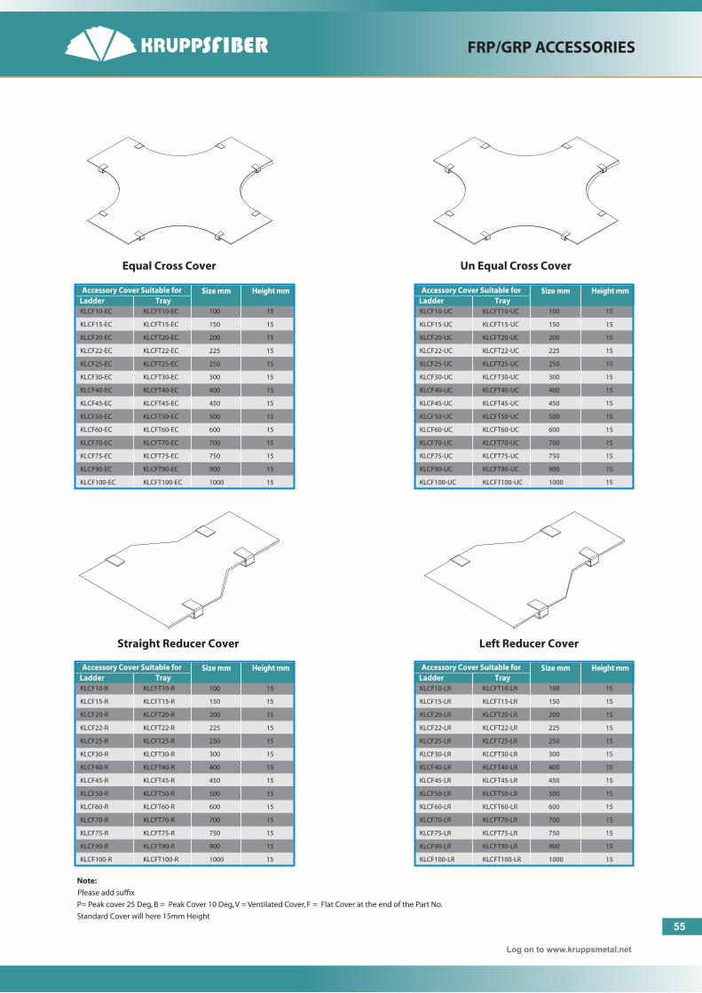
Equal Cross Cover Un Equal Cross Cover
Note:
Please add suffix
P= Peak cover 25 Deg, B = Peak Cover 10 Deg, V = Ventilated Cover, F = Flat Cover at the end of the Part No.
Standard Cover will here 15mm Height
Straight Reducer Cover Left Reducer Cover
Accessory Cover Suitable forLadder Tray
Size mm Height mm
KLCF10-EC KLCFT10-EC 100 15
KLCF15-EC KLCFT15-EC 150 15
KLCF20-EC KLCFT20-EC 200 15
KLCF22-EC KLCFT22-EC 225 15
KLCF25-EC KLCFT25-EC 250 15
KLCF30-EC KLCFT30-EC 300 15
KLCF40-EC KLCFT40-EC 400 15
KLCF45-EC KLCFT45-EC 450 15
KLCF50-EC KLCFT50-EC 500 15
KLCF60-EC KLCFT60-EC 600 15
KLCF70-EC KLCFT70-EC 700 15
KLCF75-EC KLCFT75-EC 750 15
KLCF90-EC KLCFT90-EC 900 15
KLCF100-EC KLCFT100-EC 1000 15
Accessory Cover Suitable forLadder Tray
Size mm Height mm
KLCF10-UC KLCFT10-UC 100 15
KLCF15-UC KLCFT15-UC 150 15
KLCF20-UC KLCFT20-UC 200 15
KLCF22-UC KLCFT22-UC 225 15
KLCF25-UC KLCFT25-UC 250 15
KLCF30-UC KLCFT30-UC 300 15
KLCF40-UC KLCFT40-UC 400 15
KLCF45-UC KLCFT45-UC 450 15
KLCF50-UC KLCFT50-UC 500 15
KLCF60-UC KLCFT60-UC 600 15
KLCF70-UC KLCFT70-UC 700 15
KLCF75-UC KLCFT75-UC 750 15
KLCF90-UC KLCFT90-UC 900 15
KLCF100-UC KLCFT100-UC 1000 15
Accessory Cover Suitable forLadder Tray
Size mm Height mm
KLCF10-R KLCFT10-R 100 15
KLCF15-R KLCFT15-R 150 15
KLCF20-R KLCFT20-R 200 15
KLCF22-R KLCFT22-R 225 15
KLCF25-R KLCFT25-R 250 15
KLCF30-R KLCFT30-R 300 15
KLCF40-R KLCFT40-R 400 15
KLCF45-R KLCFT45-R 450 15
KLCF50-R KLCFT50-R 500 15
KLCF60-R KLCFT60-R 600 15
KLCF70-R KLCFT70-R 700 15
KLCF75-R KLCFT75-R 750 15
KLCF90-R KLCFT90-R 900 15
KLCF100-R KLCFT100-R 1000 15
Accessory Cover Suitable forLadder Tray
Size mm Height mm
KLCF10-LR KLCFT10-LR 100 15
KLCF15-LR KLCFT15-LR 150 15
KLCF20-LR KLCFT20-LR 200 15
KLCF22-LR KLCFT22-LR 225 15
KLCF25-LR KLCFT25-LR 250 15
KLCF30-LR KLCFT30-LR 300 15
KLCF40-LR KLCFT40-LR 400 15
KLCF45-LR KLCFT45-LR 450 15
KLCF50-LR KLCFT50-LR 500 15
KLCF60-LR KLCFT60-LR 600 15
KLCF70-LR KLCFT70-LR 700 15
KLCF75-LR KLCFT75-LR 750 15
KLCF90-LR KLCFT90-LR 900 15
KLCF100-LR KLCFT100-LR 1000 15

FRP/GRP ACCESSORIES
Log on to www.kruppsmetal.net
External Riser Cover 45˚ Internal Riser Cover 90˚
Right Offset Reducer Cover External Riser Cover 90˚
Accessory Cover Suitable forLadder Tray
Size mm Height mm
KLCF10-RR KLCFT10-RR 100 15
KLCF15-RR KLCFT15-RR 150 15
KLCF20-RR KLCFT20-RR 200 15
KLCF22-RR KLCFT22-RR 225 15
KLCF25-RR KLCFT25-RR 250 15
KLCF30-RR KLCFT30-RR 300 15
KLCF40-RR KLCFT40-RR 400 15
KLCF45-RR KLCFT45-RR 450 15
KLCF50-RR KLCFT50-RR 500 15
KLCF60-RR KLCFT60-RR 600 15
KLCF70-RR KLCFT70-RR 700 15
KLCF75-RR KLCFT75-RR 750 15
KLCF90-RR KLCFT90-RR 900 15
KLCF100-RR KLCFT100-RR 1000 15
Accessory Cover Suitable forLadder Tray
Size mm Height mm
KLCF10-ER90 KLCFT10-ER90 100 15
KLCF15-ER90 KLCFT15-ER90 150 15
KLCF20-ER90 KLCFT20-ER90 200 15
KLCF22-ER90 KLCFT22-ER90 225 15
KLCF25-ER90 KLCFT25-ER90 250 15
KLCF30-ER90 KLCFT30-ER90 300 15
KLCF40-ER90 KLCFT40-ER90 400 15
KLCF45-ER90 KLCFT45-ER90 450 15
KLCF50-ER90 KLCFT50-ER90 500 15
KLCF60-ER90 KLCFT60-ER90 600 15
KLCF70-ER90 KLCFT70-ER90 700 15
KLCF75-ER90 KLCFT75-ER90 750 15
KLCF90-ER90 KLCFT90-ER90 900 15
KLCF100-ER90 KLCFT100-ER90 1000 15
Accessory Cover Suitable forLadder Tray
Size mm Height mm
KLCF10-ER45 KLCFT10-ER45 100 15
KLCF15-ER45 KLCFT15-ER45 150 15
KLCF20-ER45 KLCFT20-ER45 200 15
KLCF22-ER45 KLCFT22-ER45 225 15
KLCF25-ER45 KLCFT25-ER45 250 15
KLCF30-ER45 KLCFT30-ER45 300 15
KLCF40-ER45 KLCFT40-ER45 400 15
KLCF45-ER45 KLCFT45-ER45 450 15
KLCF50-ER45 KLCFT50-ER45 500 15
KLCF60-ER45 KLCFT60-ER45 600 15
KLCF70-ER45 KLCFT70-ER45 700 15
KLCF75-ER45 KLCFT75-ER45 750 15
KLCF90-ER45 KLCFT90-ER45 900 15
KLCF100-ER45 KLCFT100-ER45 1000 15
Accessory Cover Suitable forLadder Tray
Size mm Height mm
KLCF10-IR90 KLCFT10-IR90 100 15
KLCF15-IR90 KLCFT15-IR90 150 15
KLCF20-IR90 KLCFT20-IR90 200 15
KLCF22-IR90 KLCFT22-IR90 225 15
KLCF25-IR90 KLCFT25-IR90 250 15
KLCF30-IR90 KLCFT30-IR90 300 15
KLCF40-IR90 KLCFT40-IR90 400 15
KLCF45-IR90 KLCFT45-IR90 450 15
KLCF50-IR90 KLCFT50-IR90 500 15
KLCF60-IR90 KLCFT60-IR90 600 15
KLCF70-IR90 KLCFT70-IR90 700 15
KLCF75-IR90 KLCFT75-IR90 750 15
KLCF90-IR90 KLCFT90-IR90 900 15
KLCF100-IR90 KLCFT100-IR90 1000 15
56

FRP/GRP ACCESSORIES
57
Log on to www.kruppsmetal.net
Ladder CoverInternal Riser Cover 45˚
Accessory Cover Suitable forLadder Tray
Size mm Height mm
KLCF10-IR45 KLCFT10-IR45 100 15
KLCF15-IR45 KLCFT15-IR45 150 15
KLCF20-IR45 KLCFT20-IR45 200 15
KLCF22-IR45 KLCFT22-IR45 225 15
KLCF25-IR45 KLCFT25-IR45 250 15
KLCF30-IR45 KLCFT30-IR45 300 15
KLCF40-IR45 KLCFT40-IR45 400 15
KLCF45-IR45 KLCFT45-IR45 450 15
KLCF50-IR45 KLCFT50-IR45 500 15
KLCF60-IR45 KLCFT60-IR45 600 15
KLCF70-IR45 KLCFT70-IR45 700 15
KLCF75-IR45 KLCFT75-IR45 750 15
KLCF90-IR45 KLCFT90-IR45 900 15
KLCF100-IR45 KLCFT100-IR45 1000 15
Accessory Cover Suitable forLadder Tray
Size mm Height mm
KLCF10 KLCFT10 100 15
KLCF15 KLCFT15 150 15
KLCF20 KLCFT20 200 15
KLCF22 KLCFT22 225 15
KLCF25 KLCFT25 250 15
KLCF30 KLCFT30 300 15
KLCF40 KLCFT40 400 15
KLCF45 KLCFT45 450 15
KLCF50 KLCFT50 500 15
KLCF60 KLCFT60 600 15
KLCF70 KLCFT70 700 15
KLCF75 KLCFT75 750 15
KLCF90 KLCFT90 900 15
KLCF100 KLCFT100 1000 15
Accessory Cover Suitable forLadder Tray
Size mm Height mm
KLVCF10 KLVCFT10 100 15
KLVCF15 KLVCFT15 150 15
KLVCF20 KLVCFT20 200 15
KLVCF22 KLVCFT22 225 15
KLVCF25 KLVCFT25 250 15
KLVCF30 KLVCFT30 300 15
KLVCF40 KLVCFT40 400 15
KLVCF45 KLVCFT45 450 15
KLVCF50 KLVCFT50 500 15
KLVCF60 KLVCFT60 600 15
KLVCF70 KLVCFT70 700 15
KLVCF75 KLVCFT75 750 15
KLVCF90 KLVCFT90 900 15
KLVCF100 KLVCFT100 1000 15
Accessory Cover Suitable forLadder Tray
Size mm Height mm
KLCFF10 KLCFTT10 100 -
KLCFF15 KLCFTT15 150 -
KLCFF20 KLCFTT20 200 -
KLCFF22 KLCFTT22 225 -
KLCFF25 KLCFTT25 250 -
KLCFF30 KLCFTT30 300 -
KLCFF40 KLCFTT40 400 -
KLCFF45 KLCFTT45 450 -
KLCFF50 KLCFTT50 500 -
KLCFF60 KLCFTT60 600 -
KLCFF70 KLCFTT70 700 -
KLCFF75 KLCFT75 750 -
KLCFF90 KLCFFT90 900 -
KLCFF100 KLCFFT100 1000 -
Flat CoverVentilated Cover

FRP/GRP ACCESSORIES
58
Log on to www.kruppsmetal.net
Peak Cover 25˚
25˚
Peak Cover 10˚
10˚
Accessory Cover Suitable forLadder Tray
Size mm Height mm
KLPLF10 KLPLFT10 100 -
KLPLF15 KLPLFT15 150 -
KLPLF20 KLPLFT20 200 -
KLPLF22 KLPLFT22 225 -
KLPLF25 KLPLFT25 250 -
KLPLF30 KLPLFT30 300 -
KLPLF40 KLPLFT40 400 -
KLPLF45 KLPLFT45 450 -
KLPLF50 KLPLFT50 500 -
KLPLF60 KLPLFT60 600 -
KLPLF70 KLPLFT70 700 -
KLPLF75 KLPLFT75 750 -
KLPLF90 KLPLFT90 900 -
KLCFF100 KLPLFT100 1000 -
Accessory Cover Suitable forLadder Tray
Size mm Height mm
KLBCF10 KLBCFT10 100 -
KLBCF15 KLBCFT15 150 -
KLBCF20 KLBCFT20 200 -
KLBCF22 KLBCFT22 225 -
KLBCF25 KLBCFT25 250 -
KLBCF30 KLBCFT30 300 -
KLBCF40 KLBCFT40 400 -
KLBCF45 KLBCFT45 450 -
KLBCF50 KLBCFT50 500 -
KLBCF60 KLBCFT60 600 -
KLBCF70 KLBCFT70 700 -
KLBCF75 KLBCFT75 750 -
KLBCF90 KLBCFT90 900 -
KLBCF100 KLBCFT100 1000 -

FRP/GRP ACCESSORIES
59
Log on to www.kruppsmetal.net
Straight Coupler
Couplers
Vertical CouplerHorizantal Coupler
Verticle Straight Coupler Horizantal Straight Coupler Splice Plate and Fixture
Raised Coupler90˚ Splice Plate
90 °
H
1"
6"
Model Height
KSLF-50 50m
KSLF-75 75m
KSLF-100 100m
KSLF-125 125m
KSLF-150 150m
KSLF-175 175m
Model Height
KHCF-50 50m
KHCF-75 75m
KHCF-100 100m
KHCF-125 125m
KHCF-150 150m
KHCF-175 175m
Model Height
KVCF-50 50m
KVCF-75 75m
KVCF-100 100m
KVCF-125 125m
KVCF-150 150m
KVCF-175 175m
Model Height
KVSCF-50 50m
KVSCF-75 75m
KVSCF-100 100m
KVSCF-125 125m
KVSCF-150 150m
KVSCF-175 175m
Model Height
KHSCF-50 50m
KHSCF-75 75m
KHSCF-100 100m
KHSCF-125 125m
KHSCF-150 150m
KHSCF-175 175m
Model Height
KSPFF-50 50m
KSPFF-75 75m
KSPFF-100 100m
KSPFF-125 125m
KSPFF-150 150m
KSPFF-175 175m
Model Height
KSPF90-50 50m
KSPF90-75 75m
KSPF90-100 100m
KSPF90-125 125m
KSPF90-150 150m
KSPF90-175 175m
Model Height
KRCF-50 50m
KRCF-75 75m
KRCF-100 100m
KRCF-125 125m
KRCF-150 150m
KRCF-175 175m
Straight Coupler 8 Hole
Model Height
KSL8F-50 50m
KSL8F-75 75m
KSL8F-100 100m
KSL8F-125 125m
KSL8F-150 150m
KSL8F-175 175m

60
GRP / FRP TRAY

Log on to www.kruppsmetal.net
61
GRP / FRP TRAY
KFT - C - 15 - 2 - P - 3
CABLE TRAY SELECTION CHART
Type Profile
I
10 = 100m15 = 150m20 = 200m22 = 225m25 = 250m30 = 300m35 = 350m40 = 400m45 = 450m50 = 500m60 = 600m75 = 750m90 = 900m
KFT
Width
2 = 50m3 = 75m4 = 100m
Side Rail
Resin 3=3mtr6 = 6mtr
Length
P = Polyester ResinV = Vinyl EsterH = Hologen Free PolyesterHL = Hologen Free Low SmokeHVS = Hologen Free Vinyl EsterRT = Conductive
KFTA - C - 15 - 2 - P - HB90
CABLE TRAY ACCESSORIES SELECTION CHART
Type Profile
I
10 = 100m15 = 150m20 = 200m22 = 225m25 = 250m30 = 300m35 = 350m40 = 400m45 = 450m50 = 500m60 = 600m75 = 750m90 = 900m
KFTA
Width
2 = 50m3 = 75m4 = 100m
HB90- Horizontal Bend 90 ˚HB45 - Horizontal Bend 45˚IB90 - Internal Bend 90˚IB45 - Internal Bend 45˚EB90 - External Bend 90˚EB45 - External Bend 45˚HT - Horizontal Equal Tee - HUC - Horizontal Un Equal Tee
Side Rail
Type
Resin
P = Polyester ResinV = Vinyl EsterH = Hologen Free PolyesterHL = Hologen Free Low SmokeHVS = Hologen Free Vinyl EsterRT = Conductive

ACCESSORIES
Log on to www.kruppsmetal.net
R
W
R
W
R
W
R
W
W
W
W
W
45˚ Internal Bend 45˚ External Bend
R
W
R
W
90˚ Internal Bend 90˚ External Bend
90˚ Horizontal Bend 45˚ Horizontal Bend
Horizontal Un Equal Tee Horizontal Un Equal Cross
62

ACCESSORIES
63
Log on to www.kruppsmetal.net
Straight Coupler
Couplers
Vertical CouplerHorizantal Coupler
Verticle Straight Coupler Horizantal Straight Coupler Splice Plate and Fixture
Raised Coupler90˚ Splice Plate
90 °
H
1"
6"
Model Height
KSLFT-50 50m
KSLFT-75 75m
KSLFT-100 100m
KSLFT-125 125m
KSLFT-150 150m
KSLFT-175 175m
Model Height
KHCFT-50 50m
KHCFT-75 75m
KHCFT-100 100m
KHCFT-125 125m
KHCFT-150 150m
KHCFT-175 175m
Model Height
KVCFT-50 50m
KVCFT-75 75m
KVCFT-100 100m
KVCFT-125 125m
KVCFT-150 150m
KVCFT-175 175m
Model Height
KVSCFT-50 50m
KVSCFT-75 75m
KVSCFT-100 100m
KVSCFT-125 125m
KVSCFT-150 150m
KVSCFT-175 175m
Model Height
KHSCFT-50 50m
KHSCFT-75 75m
KHSCFT-100 100m
KHSCFT-125 125m
KHSCFT-150 150m
KHSCFT-175 175m
Model Height
KSPFFT-50 50m
KSPFFT-75 75m
KSPFFT-100 100m
KSPFFT-125 125m
KSPFFT-150 150m
KSPFFT-175 175m
Model Height
KSPFT90-50 50m
KSPFT90-75 75m
KSPFT90-100 100m
KSPFT90-125 125m
KSPFT90-150 150m
KSPFT90-175 175m
Model Height
KRCFT-50 50m
KRCFT-75 75m
KRCFT-100 100m
KRCFT-125 125m
KRCFT-150 150m
KRCFT-175 175m
Straight Coupler 8 Hole
Model Height
KSL8FT-50 50m
KSL8FT-75 75m
KSL8FT-100 100m
KSL8FT-125 125m
KSL8FT-150 150m
KSL8FT-175 175m

FRP/GRP STRUT
Pipe Support Racks Sample Installation Wall Stanchion Sample Installation
Clevis Hanger
Pipe Clamps
Connector Plates
Channel Framing (EC158D)
Channel Framing (EC158)
Strut PostBase Multi-Tiered
Support Racks
4.0 Non-Metallic Pipe Clamps
4.1 All pipe clamps shall be manufactured by the injection molding process with an impact modified, 30% glass filled thermoplastic polyester resin.
4.2 All pipe clamps interlock with the channel framing described above.
4.3 All pipe clamps shall be designed for rigid PVC coated steel, Schedule 40 and 80 PVC, and filament wound fiberglass pipe or conduit. Clamps shall be adjustable to accommodate a 3/4 minimum deviation in O.D. size.
5.0 Fasteners
5.1 All fasteners shall be injected molded glass reinforced nylon, 316 stainless steel, or pulturded vinyl easter rod with ground threads and compression molded vinyl ester nuts.
Note:
For Strut Channel and its accessories please select from Kruppsstrut Catalogue.
Kruppsmetal strut combined with our cable tray accessories are functional in many non-cable tray applications. Strut includes all the items nessary to field fabricate to your specifications whether wall, floor, or ceiling mounted. Krupps-metal can also assist in engineering to your requirements.
If you need a special shape or assembly, call Enduro for information on custom pultrusions and fabricatioris.
Specification
1.0 Scope
1.1 This specification covers the requirements for Krupps-metal non-metallic Channel framing systems & accessories..
2.0 Standards
2.1 All channel shall have a fiame spread rating of 25 or less, and the smoke developed index shall have a density of 450 or less when tested in accordance with the provisions of ASTM E-84; therefore qualifiying as a class 1 material in the uniform building code.
3.0 Mdsaterials
3.1 All channel shall be manufactured by the pultrusion process, and contain a minimum of 50% glass by weight.
3.2 All channel shall conform, as a minimum requirement, to loads and defiections shown on the tables in the latest version of the Enduro Technical Catalogue.
64

KRUPPSMETAL Corporation.Barnet Street, Yarravilla, Victoria 3013Australia.
Email: [email protected]
Middle East Marketing Office:
Delta GroupTel : +973 17280009 / 17280200Fax : +973 17280449Manama, Kingdom of BahrainE-mail: [email protected]: www.deltaelectricals.com
Kruppsmetal Corporation Consists of these Products