cable support systems cable trays and integrated ceilings
TRANSCRIPT
Cable Support Systems
Cable Trays and Integrated Ceilings
October 2000

WIBE was the first producer of cable ladders in Sweden andhas for more than 70 years been the market leader andforemost in the development of new products and systems.Today we produce a wide programme for cable supportsoffering: Cable ladders Cable trays and Integrated Ceilings Lighting trunking Carrier system for light cables Installation rails and channelsWIBE has the unique advantage of being able to offer you acable support system for each specific building sector all fromone source.WIBE produces more than 1 million metres of cable laddereach year at our modern, 18 000 m2 factory in Mora.Our own hot dip galvanizing plant is one of the most modernin Northern Europe and has a capacity of 90 tons a day, closeby is the painting plant which is one of the most advancedplants for powder coating in the world.
WIBE can offer you coatings to meet most of your corrosionprotection requirements coupled with the colour of yourchoice.When it comes to know how and service we will help you findthe best solution, because our total resources are at yourdisposal.Our sales organisation in partnership with distributors andstockists all over the world guarantee you speedy deliveries.You may already know that WIBE is also the market leader inclimbing ladders as well as masts used for lighting andcommunications.WIBE has a complete range of professional climbing laddersto meet the demands of both industrial and domestic users.The climbing ladders are produced at our plant in NässjöSweden.Masts have been manufactured by WIBE since the mid 40'sand range from 6 m to 335 m high. They are technicallyadvanced both in design and construction. Needless to saywe have the resources for qualified projection, calculation andconstruction and our specialist installation teams haveexperience gained from countless projects world wide.
WIBE in Mora, Sweden

3
Cable trays – view 4
Surface treatment, Environmental policy and Quality certification 6
Potential balancing 9
Cable trays – installation summary 10
Suspension components – installation summary 12
Cable trays W1 and W3 14
Lighting trunking W70/W71 17
Support bracket W20, W20A, Support bracket W1940 19
Cantilever arm W17, - W1840, - 50, - 70, - 80 21
Wall bracket 80, Mounting rail 40, Side joint W3, Support bracket/joint W7 27
Pendant attachment W21, Tube pendant attachment W73, Pendant bracket W80, - 81 31
Ceiling bracket 7, Ceiling attachment W31, Ceiling bracket 5 33
P/F-rail 24/34, P/F-rail 7L and 7, Pendant rail W32, Pendant strip W33, Vertical pieces 7L/7, - 2/2F, - 20 35
Pendant bar 1, Bracket 60/40, Locking clamp W77, Angle bracket W8, - W8S 44
T-joint W9, T-joint W29 49
Adjustable bend W10S, 90° bend W10 SKH, T-junction W12 SKH, X-junction W13 SKH, Cover plate W16 51
Reducing piece W14, - W15, End cover W45, Vertical riser W11 55
Dividing strip 39/24, Support band W6, Insert piece W39, Tele-conduit 36 58
Cover W5, Cover clamp W62 60
Junction box plate W24 61
Earth clamp W79, Luminaire bracket W56, - W55, - W35, - W25, - W50, Strip fixing W44 62
End plug 7, 28E and 28D 66
Installation tray W4 – outline of assembly, Installation tray W4, Joint W4, 90° bend W4, Vertical riser W4 67
Mesh trays – outline of assembly, Mesh tray WN62, Ceiling mesh tray WN2, Angle mesh tray WN1 72
Mesh trays – accessories 76
Screw sets, Ogebe fixings, Repair paint 92
Integrated ceilings 101
Position retainer W43 and Support W42, Gypsum clip, Frame clip W90, Profile W-swing 1–5 112
Shade ledge W26, Supp. channel W27, Angle strip W46, Wall tray 60 118
Cable trays
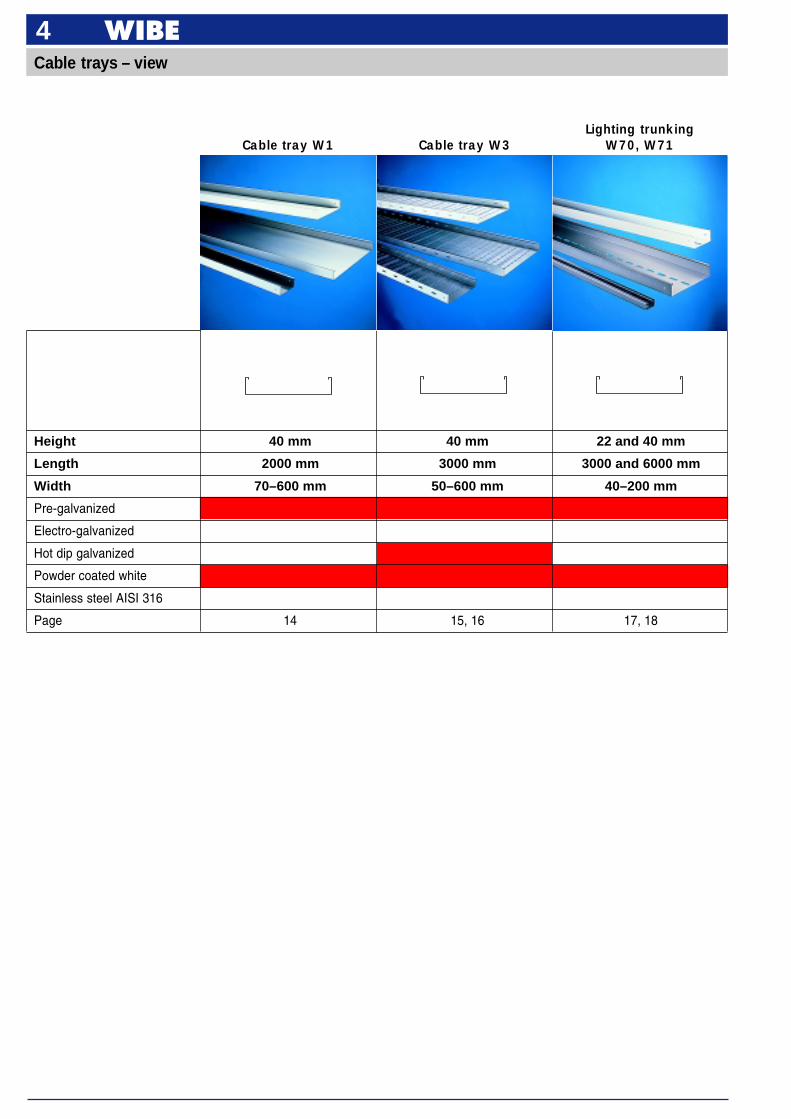
4Cable trays – view
Cable tray W3Cable tray W1
Height 40 mm 40 mm 22 and 40 mm
Length 2000 mm 3000 mm 3000 and 6000 mm
Width 70–600 mm 50–600 mm 40–200 mm
Pre-galvanized
Electro-galvanized
Hot dip galvanized
Powder coated white
Stainless steel AISI 316
Page 14 15, 16 17, 18
Lighting trunkingW70, W71
5
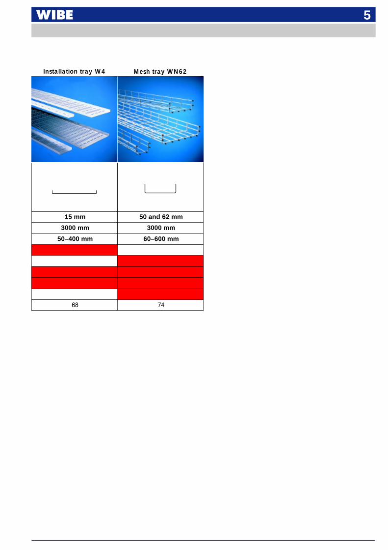
Mesh tray WN62
15 mm 50 and 62 mm
3000 mm 3000 mm
50–400 mm 60–600 mm
68 74
Installation tray W4
6Surface treatment
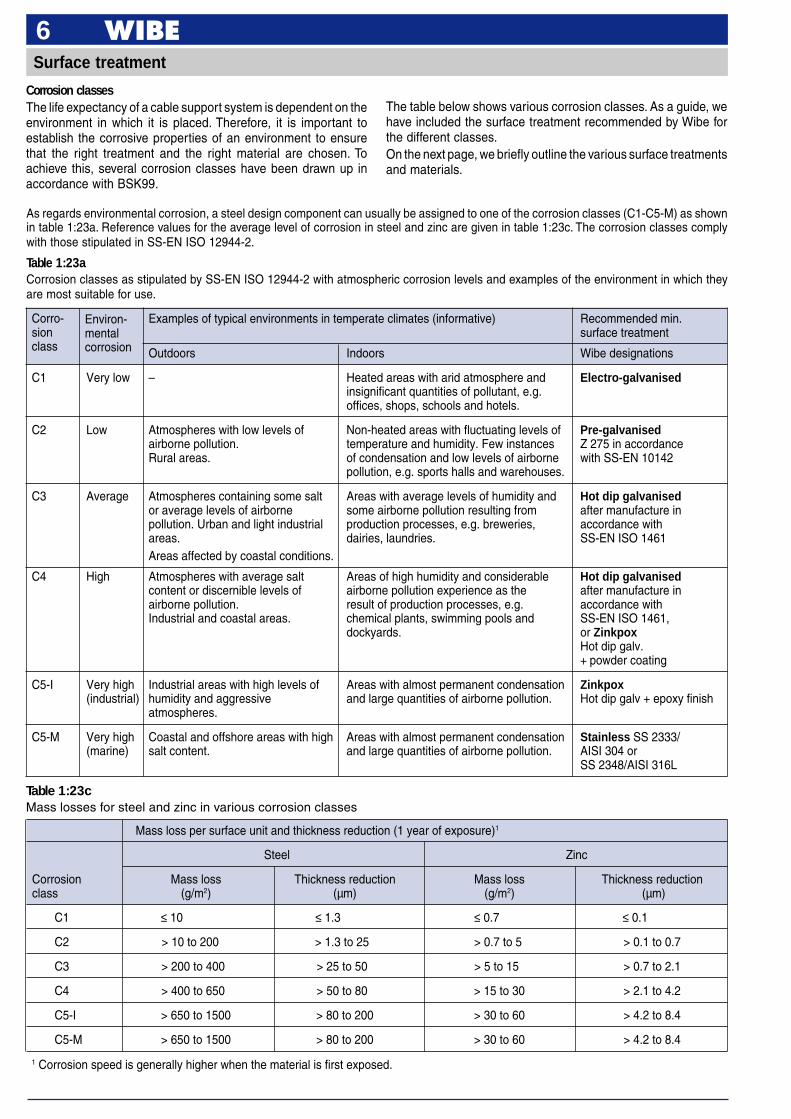
Corrosion classesThe life expectancy of a cable support system is dependent on theenvironment in which it is placed. Therefore, it is important toestablish the corrosive properties of an environment to ensurethat the right treatment and the right material are chosen. Toachieve this, several corrosion classes have been drawn up inaccordance with BSK99.
The table below shows various corrosion classes. As a guide, wehave included the surface treatment recommended by Wibe forthe different classes.On the next page, we briefly outline the various surface treatmentsand materials.
Mass loss per surface unit and thickness reduction (1 year of exposure)1
Steel Zinc
Corrosion Mass loss Thickness reduction Mass loss Thickness reductionclass (g/m2) (µm) (g/m2) (µm)
C1 ≤ 10 ≤ 1.3 ≤ 0.7 ≤ 0.1
C2 > 10 to 200 > 1.3 to 25 > 0.7 to 5 > 0.1 to 0.7
C3 > 200 to 400 > 25 to 50 > 5 to 15 > 0.7 to 2.1
C4 > 400 to 650 > 50 to 80 > 15 to 30 > 2.1 to 4.2
C5-I > 650 to 1500 > 80 to 200 > 30 to 60 > 4.2 to 8.4
C5-M > 650 to 1500 > 80 to 200 > 30 to 60 > 4.2 to 8.4
Table 1:23cMass losses for steel and zinc in various corrosion classes
1 Corrosion speed is generally higher when the material is first exposed.
Examples of typical environments in temperate climates (informative) Recommended min.surface treatment
Outdoors Indoors Wibe designations
C1 Very low – Heated areas with arid atmosphere and Electro-galvanisedinsignificant quantities of pollutant, e.g.offices, shops, schools and hotels.
C2 Low Atmospheres with low levels of Non-heated areas with fluctuating levels of Pre-galvanisedairborne pollution. temperature and humidity. Few instances Z 275 in accordanceRural areas. of condensation and low levels of airborne with SS-EN 10142
pollution, e.g. sports halls and warehouses.
C3 Average Atmospheres containing some salt Areas with average levels of humidity and Hot dip galvanisedor average levels of airborne some airborne pollution resulting from after manufacture inpollution. Urban and light industrial production processes, e.g. breweries, accordance withareas. dairies, laundries. SS-EN ISO 1461Areas affected by coastal conditions.
C4 High Atmospheres with average salt Areas of high humidity and considerable Hot dip galvanisedcontent or discernible levels of airborne pollution experience as the after manufacture inairborne pollution. result of production processes, e.g. accordance withIndustrial and coastal areas. chemical plants, swimming pools and SS-EN ISO 1461,
dockyards. or ZinkpoxHot dip galv.+ powder coating
C5-I Very high Industrial areas with high levels of Areas with almost permanent condensation Zinkpox(industrial) humidity and aggressive and large quantities of airborne pollution. Hot dip galv + epoxy finish
atmospheres.
C5-M Very high Coastal and offshore areas with high Areas with almost permanent condensation Stainless SS 2333/(marine) salt content. and large quantities of airborne pollution. AISI 304 or
SS 2348/AISI 316L
Corro-sionclass
Environ-mentalcorrosion
As regards environmental corrosion, a steel design component can usually be assigned to one of the corrosion classes (C1-C5-M) as shownin table 1:23a. Reference values for the average level of corrosion in steel and zinc are given in table 1:23c. The corrosion classes complywith those stipulated in SS-EN ISO 12944-2.
Table 1:23aCorrosion classes as stipulated by SS-EN ISO 12944-2 with atmospheric corrosion levels and examples of the environment in which theyare most suitable for use.
7Surface treatment
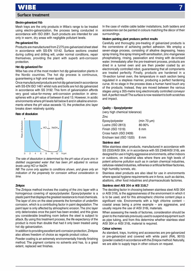
The rate of dissolution is determined by the pH value of pure zinc indistilled oxygenated water that has been pH adjusted to variouslevels using HCl or NaOH.NB The curve only applies to conditions shown, and gives only anindication of the propensity for corrosion without consideration totime.
ZinkpoxThe Zinkpox method involves the coating of the zinc layer with ahomogenous covering of epoxy/polyester. Epoxy/polyester is aplastic paint that displays the greatest resistance to most chemicals.The layer of zinc on the steel prevents the formation of underfilmcorrosion, which is a contributing factor in paint degradation. Thepaint layer is only affected by atmospheric erosion. The zinc layeronly deteriorates once the paint has been eroded, and this givesyou considerable breathing room before the steel is subject toattack. By using this treatment process, the life expectancy of theproduct is more than double that had it only been treated usinghot dip galvanization.In addition to providing excellent anti-corrosion protection, Zinkpoxalso allows freedom of choice as regards product colour.Powder coating is an extremely environmentally friendly finishingmethod. The pigment contains no solvents and has, to a greatextent, replaced wet finishes.
Electro-galvanized FzbMesh trays are the only products in Wibe’s range to be treatedusing electro-galvanization, the process being conducted inaccordance with ISO 2081. Such products are intended for useonly in warm, dry areas with negligible pollutant levels.
Pre-galvanized FzsProducts are manufactured from Z 275 pre-galvanized sheet steelin accordance with SS-EN 10142. Surface sections createdduring cutting and drilling will, under normal conditions, repairthemselves, providing the plant with superb anti-corrosionprotection.
Hot dip galvanized FzvWibe has one of the most modern hot dip galvanization plants inthe Nordic countries. The hot dip process is continuous,guaranteeing a high and even quality.Once manufactured products are hot dip galvanized in accordancewith SS-EN ISO 1461 whilst nuts and bolts are hot dip galvanizedin accordance with SS 3192. This form of galvanization affordsvery good value-for-money anti-corrosion protection in atmo-spheres with a pH value of between 6 and 13. However, in acidicenvironments where pH levels fall below 6 and in alkaline environ-ments where the pH value exceeds 13, the protective zinc layerbreaks down relatively quickly.
In the case of visible cable ladder installations, both ladders andaccessories can be painted in colours matching the décor of theirsurroundings.
Modern painting plant produces perfect resultsCarefully and thoroughly pre-treating of galvanized products isthe cornerstone of achieving perfect adhesion. We employ aseven-stage process, consisting of alkaline degreasing, heavyspray rinsing, fine spray rinsing with sensitisation, zinc-manganesephosphatising, rinsing, passivation and rinsing with de-ionisedwater. Immediately after the pre-treatment process, products aredried in a tunnel oven and are then powder coated by anelectronically controlled robot, guaranteeing that all componentsare treated perfectly. Finally, products are hardened in a19-section tunnel oven, the temperature in each section beingregulated in a stepless manner, producing a perfect hardeningcurve. At no stage in the process does a human hand touch anyof the products. Instead, they are moved between the variousstages using a 355-metre long electronically controlled conveyorbelt. A perfect result! The surface is now resistant to both scratchesand impact.
Quality – Epoxy/polyester(very high chemical tolerance)ZincEpoxy/polyester (min 70 µm)Lustre (ISO 2813) 80-90%Finish (ISO 1519) 6 mmCross hatch (ISO 2409)Erichsen test (ISO 1520) 8 mm
Stainless steelWibe stainless steel products, manufactured in accordance withSS 2333/AISI 304, or in accordance with SS 2348/AISI 316L aredesigned for use in highly aggressive environments, either indoorsor outdoors, on industrial sites where there are high levels ofpotent airborne pollution such as in certain chemical industries,cellulose-related industries, refineries or artificial fertiliser factories,high humidity tunnels, etc.Stainless steel products are also ideal for use in environmentswhere special hygiene requirements are in force, such as dairies,abattoirs, other food industries and pharmaceuticals factories.
Stainless steel AISI 304 or AISI 316L?The deciding factor in choosing between stainless steel AISI 304or AISI 316L is the aggressiveness of the environment in which itis to be used, and for this atmospheric chlorine content plays asignificant role. Environments with a high chlorine content –coastal areas being a prime example – are aggressive, andusually require the use of AISI 316L materials.When assessing the needs of factories, consideration should begiven to the materials previously used to suspend equipment suchas pipe tubing, and from this determine whether stainless steelAISI 304 or AISI 316L material is required.
Colour schemesAs standard, trays, trunking and accessories are pre-galvanizedor pre-galvanized and covered with white paint (RAL 9010)(powder coated) in accordance with the Zinkpox method. Naturally,we are able to supply trays in other colours on request.
Rate of dissolution
0 2 4 6 8 10 12 14 pH
HCI NaOH
Rat
e of
dis
solu
tion
8
Environmental product declarations are available for all Wibeproducts. These can be ordered direct from Wibe.Declarations may also be downloaded from the Wibe website atwww.wibe.comOur product sheets and brochures are marked successively withthe name of the environmental document (WEF-0001–0024).
Environmental policyIt is AB WIBE’s intention to safeguard and take responsibility forboth the internal and external environment.– By creating a good internal environment, we will prevent
incidents of illness and have a positive effect on quality andproductivity.
– We will contribute towards creating a good external environmentin the immediate area by reducing the negative effectsgenerated by emissions and waste.
– We will use cyclical analyses in the development of products,packaging and production systems in order to clarify theimpact they have on the global environment.
– Each employee shall take personal responsibility both for theirown health and for the environment in their day-to-day work byfollowing instructions and procedures, and by reporting anyapparent health and environmental hazards.
Approval and quality assurance
Environmental policy and Quality certification
1053
EN 45012
SS-EN ISO 9001CERTIFIED COMPANY
Wibe has a policy of testing and approvingproducts in accordance with current nationaland international standards. To manage ourbusiness activities, we have introduced aquality assurance system that is ISO 9001certified.
9Potential balancing
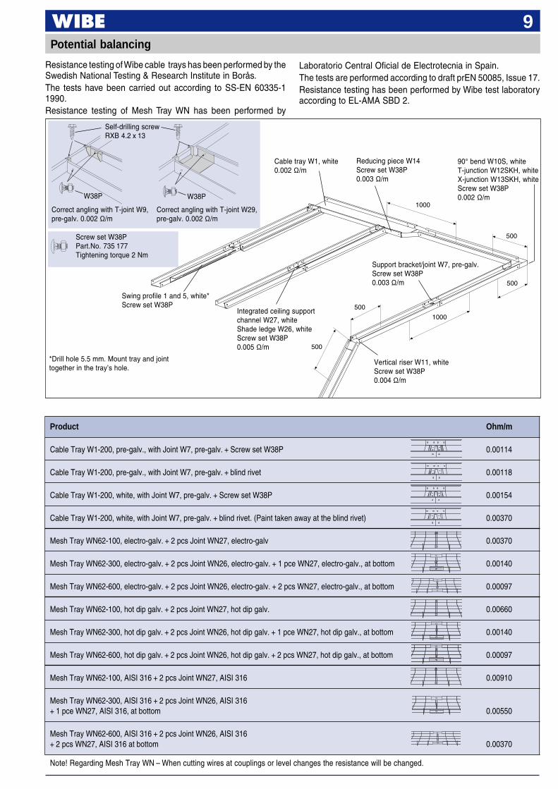
Resistance testing of Wibe cable trays has been performed by theSwedish National Testing & Research Institute in Borås.The tests have been carried out according to SS-EN 60335-11990.Resistance testing of Mesh Tray WN has been performed by
Laboratorio Central Oficial de Electrotecnia in Spain.The tests are performed according to draft prEN 50085, Issue 17.Resistance testing has been performed by Wibe test laboratoryaccording to EL-AMA SBD 2.
Product Ohm/m
Cable Tray W1-200, pre-galv., with Joint W7, pre-galv. + Screw set W38P 0.00114
Cable Tray W1-200, pre-galv., with Joint W7, pre-galv. + blind rivet 0.00118
Cable Tray W1-200, white, with Joint W7, pre-galv. + Screw set W38P 0.00154
Cable Tray W1-200, white, with Joint W7, pre-galv. + blind rivet. (Paint taken away at the blind rivet) 0.00370
Mesh Tray WN62-100, electro-galv. + 2 pcs Joint WN27, electro-galv 0.00370
Mesh Tray WN62-300, electro-galv. + 2 pcs Joint WN26, electro-galv. + 1 pce WN27, electro-galv., at bottom 0.00140
Mesh Tray WN62-600, electro-galv. + 2 pcs Joint WN26, electro-galv. + 2 pcs WN27, electro-galv., at bottom 0.00097
Mesh Tray WN62-100, hot dip galv. + 2 pcs Joint WN27, hot dip galv. 0.00660
Mesh Tray WN62-300, hot dip galv. + 2 pcs Joint WN26, hot dip galv. + 1 pce WN27, hot dip galv., at bottom 0.00140
Mesh Tray WN62-600, hot dip galv. + 2 pcs Joint WN26, hot dip galv. + 2 pcs WN27, hot dip galv., at bottom 0.00097
Mesh Tray WN62-100, AISI 316 + 2 pcs Joint WN27, AISI 316 0.00910
Mesh Tray WN62-300, AISI 316 + 2 pcs Joint WN26, AISI 316+ 1 pce WN27, AISI 316, at bottom 0.00550
Mesh Tray WN62-600, AISI 316 + 2 pcs Joint WN26, AISI 316+ 2 pcs WN27, AISI 316 at bottom 0.00370
Note! Regarding Mesh Tray WN – When cutting wires at couplings or level changes the resistance will be changed.
1000
Swing profile 1 and 5, white*Screw set W38P
Integrated ceiling supportchannel W27, whiteShade ledge W26, whiteScrew set W38P0.005 Ω/m
1000
500
500
500
500
Cable tray W1, white0.002 Ω/m
Reducing piece W14Screw set W38P0.003 Ω/m
90° bend W10S, whiteT-junction W12SKH, whiteX-junction W13SKH, whiteScrew set W38P0.002 Ω/m
Support bracket/joint W7, pre-galv.Screw set W38P0.003 Ω/m
Vertical riser W11, whiteScrew set W38P0.004 Ω/m
*Drill hole 5.5 mm. Mount tray and jointtogether in the tray’s hole.
Correct angling with T-joint W9,pre-galv. 0.002 Ω/m
Correct angling with T-joint W29,pre-galv. 0.002 Ω/m
Self-drilling screwRXB 4.2 x 13
W38P W38P
Screw set W38PPart.No. 735 177Tightening torque 2 Nm
10Cable trays – installation summary
12
54
3
4
17
8
9
10
11
12
13
14
16
22
20
23
24
25
51
37
28
29 35
34
40
41
42
60
53
46
47
50
56
57
47
46
10
56
36
52
50
49
48
38
53
4
58
59
11
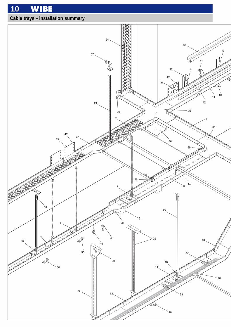
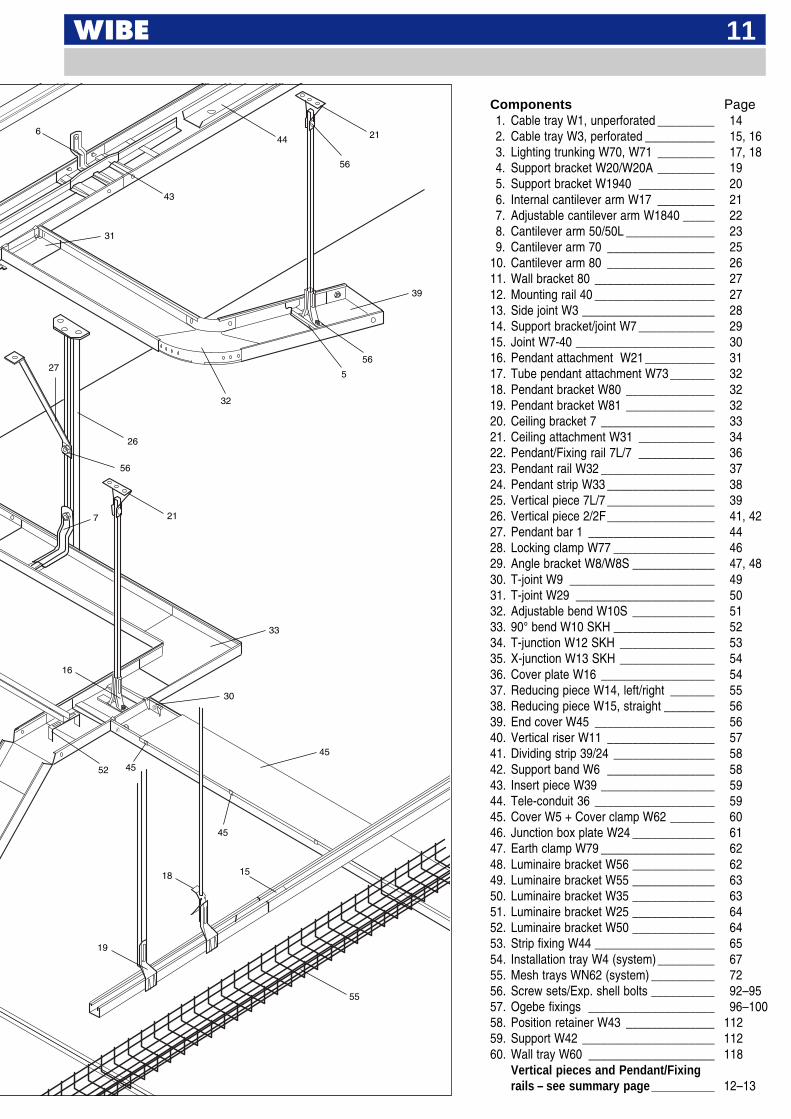
Components Page1. Cable tray W1, unperforated _________ 142. Cable tray W3, perforated ___________ 15, 163. Lighting trunking W70, W71 _________ 17, 184. Support bracket W20/W20A _________ 195. Support bracket W1940 ____________ 206. Internal cantilever arm W17 _________ 217. Adjustable cantilever arm W1840 _____ 228. Cantilever arm 50/50L ______________ 239. Cantilever arm 70 _________________ 25
10. Cantilever arm 80 _________________ 2611. Wall bracket 80 ___________________ 2712. Mounting rail 40 ___________________ 2713. Side joint W3 _____________________ 2814. Support bracket/joint W7 ____________ 2915. Joint W7-40 ______________________ 3016. Pendant attachment W21 ___________ 3117. Tube pendant attachment W73 _______ 3218. Pendant bracket W80 ______________ 3219. Pendant bracket W81 ______________ 3220. Ceiling bracket 7 __________________ 3321. Ceiling attachment W31 ____________ 3422. Pendant/Fixing rail 7L/7 ____________ 3623. Pendant rail W32 __________________ 3724. Pendant strip W33 _________________ 3825. Vertical piece 7L/7 _________________ 3926. Vertical piece 2/2F_________________ 41, 4227. Pendant bar 1 ____________________ 4428. Locking clamp W77 ________________ 4629. Angle bracket W8/W8S _____________ 47, 4830. T-joint W9 _______________________ 4931. T-joint W29 ______________________ 5032. Adjustable bend W10S _____________ 5133. 90° bend W10 SKH ________________ 5234. T-junction W12 SKH _______________ 5335. X-junction W13 SKH _______________ 5436. Cover plate W16 __________________ 5437. Reducing piece W14, left/right _______ 5538. Reducing piece W15, straight ________ 5639. End cover W45 ___________________ 5640. Vertical riser W11 _________________ 5741. Dividing strip 39/24 ________________ 5842. Support band W6 _________________ 5843. Insert piece W39 __________________ 5944. Tele-conduit 36 ___________________ 5945. Cover W5 + Cover clamp W62 _______ 6046. Junction box plate W24 _____________ 6147. Earth clamp W79 __________________ 6248. Luminaire bracket W56 _____________ 6249. Luminaire bracket W55 _____________ 6350. Luminaire bracket W35 _____________ 6351. Luminaire bracket W25 _____________ 6452. Luminaire bracket W50 _____________ 6453. Strip fixing W44 ___________________ 6554. Installation tray W4 (system)_________ 6755. Mesh trays WN62 (system) __________ 7256. Screw sets/Exp. shell bolts __________ 92–9557. Ogebe fixings ____________________ 96–10058. Position retainer W43 ______________ 11259. Support W42 _____________________ 11260. Wall tray W60 ____________________ 118
Vertical pieces and Pendant/Fixingrails – see summary page__________ 12–13
55
6
7
5
19
18
21
26
27
31
32
33
39
52
45
43
21
15
30
56
44
56
56
16
45
45
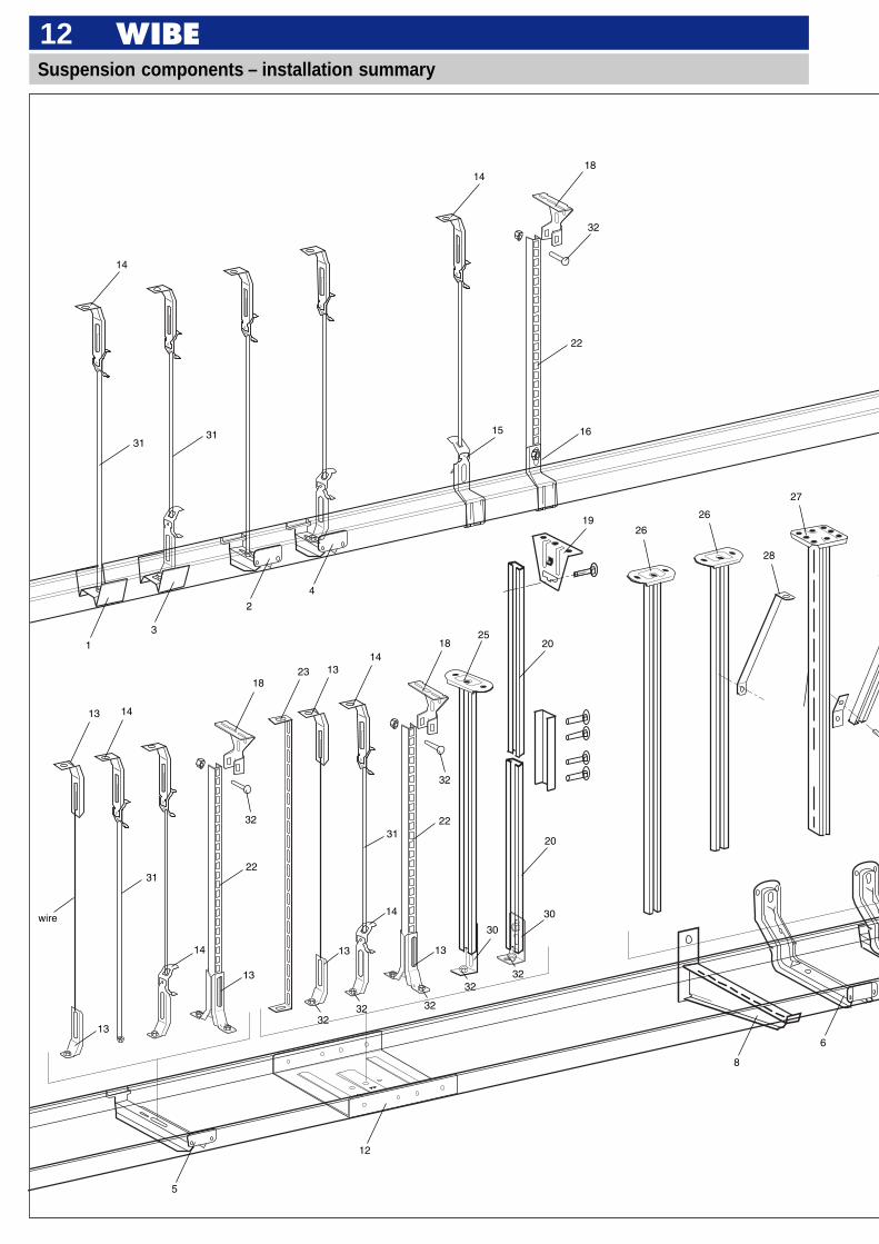
12Suspension components – installation summary
311615
1
14
1418
19
3
2
4
13 14
1823
1814
13
3122
22
30
28
12
5
8
6
20
32
wire
31
13
14
13
13
14
13
30
26
26
31
22
32
32
3232 32
3232
25
20
27
13
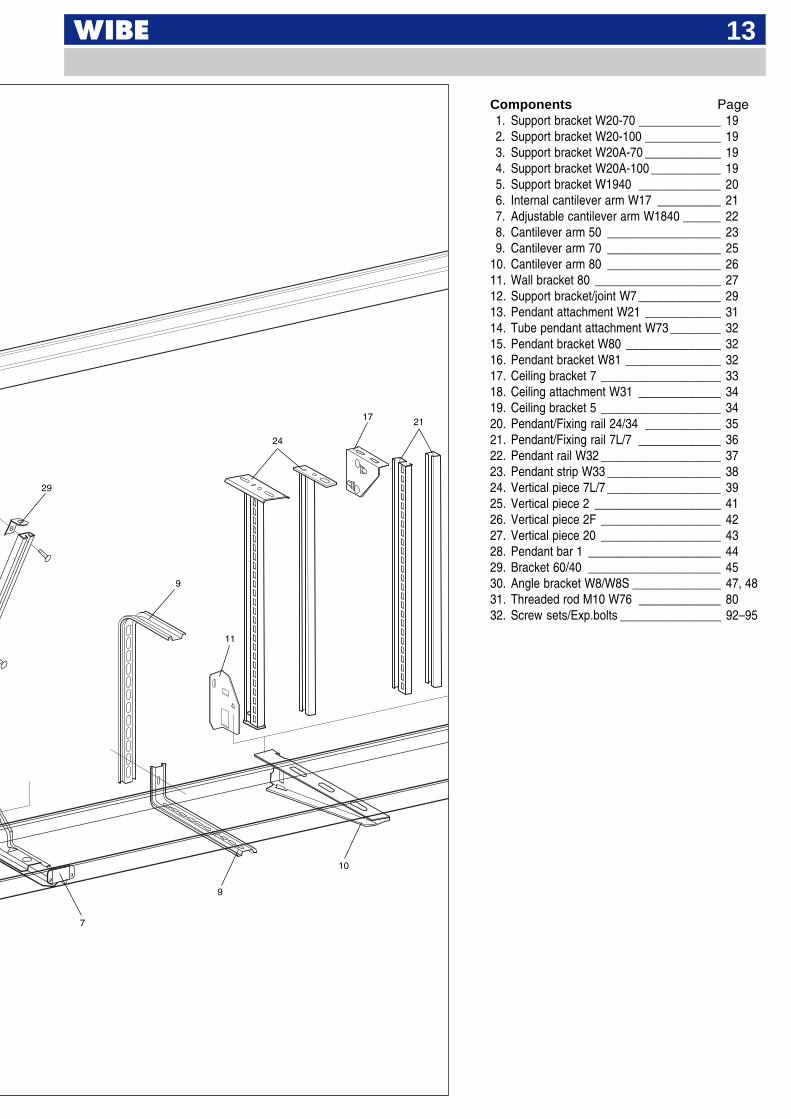
Components Page1. Support bracket W20-70 _____________ 192. Support bracket W20-100 ____________ 193. Support bracket W20A-70 ____________ 194. Support bracket W20A-100 ___________ 195. Support bracket W1940 _____________ 206. Internal cantilever arm W17 __________ 217. Adjustable cantilever arm W1840 ______ 228. Cantilever arm 50 __________________ 239. Cantilever arm 70 __________________ 25
10. Cantilever arm 80 __________________ 2611. Wall bracket 80 ____________________ 2712. Support bracket/joint W7 _____________ 2913. Pendant attachment W21 ____________ 3114. Tube pendant attachment W73 ________ 3215. Pendant bracket W80 _______________ 3216. Pendant bracket W81 _______________ 3217. Ceiling bracket 7 ___________________ 3318. Ceiling attachment W31 _____________ 3419. Ceiling bracket 5 ___________________ 3420. Pendant/Fixing rail 24/34 ____________ 3521. Pendant/Fixing rail 7L/7 _____________ 3622. Pendant rail W32 ___________________ 3723. Pendant strip W33 __________________ 3824. Vertical piece 7L/7 __________________ 3925. Vertical piece 2 ____________________ 4126. Vertical piece 2F ___________________ 4227. Vertical piece 20 ___________________ 4328. Pendant bar 1 _____________________ 4429. Bracket 60/40 _____________________ 4530. Angle bracket W8/W8S ______________ 47, 4831. Threaded rod M10 W76 _____________ 8032. Screw sets/Exp.bolts ________________ 92–95
29
9
24
17 21
11
7
9
10
* EAN-code = 732167 + Part.no + C (control figure)
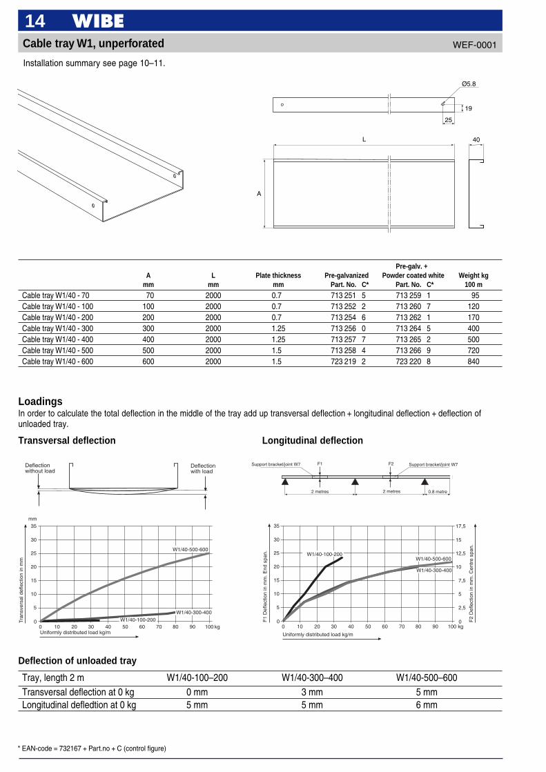
14Cable tray W1, unperforated
Installation summary see page 10–11.
Pre-galv. +A L Plate thickness Pre-galvanized Powder coated white Weight kg
mm mm mm Part. No. C* Part. No. C* 100 m
Cable tray W1/40 - 70 70 2000 0.7 713 251 5 713 259 1 95Cable tray W1/40 - 100 100 2000 0.7 713 252 2 713 260 7 120Cable tray W1/40 - 200 200 2000 0.7 713 254 6 713 262 1 170Cable tray W1/40 - 300 300 2000 1.25 713 256 0 713 264 5 400Cable tray W1/40 - 400 400 2000 1.25 713 257 7 713 265 2 500Cable tray W1/40 - 500 500 2000 1.5 713 258 4 713 266 9 720Cable tray W1/40 - 600 600 2000 1.5 723 219 2 723 220 8 840
WEF-0001
Deflection of unloaded tray
Tray, length 2 m W1/40-100–200 W1/40-300–400 W1/40-500–600Transversal deflection at 0 kg 0 mm 3 mm 5 mmLongitudinal defledtion at 0 kg 5 mm 5 mm 6 mm
LoadingsIn order to calculate the total deflection in the middle of the tray add up transversal deflection + longitudinal deflection + deflection ofunloaded tray.
Transversal deflection Longitudinal deflection
F2
2 metres 2 metres
Support bracket/joint W7
0.8 metre
F1 Support bracket/joint W7
0
5
10
15
20
25
30
35
0 10 20 30 40 50 60 70 80 90 100
mm
kg
Tran
sver
sal d
efle
ctio
n in
mm
Uniformly distributed load kg/m
W1/40-300-400
W1/40-500-600
W1/40-100-200 0
5
10
15
20
25
30
35
0
2,5
5
7,5
10
12,5
15
17,5
0 10 20 30 40 50 60 70 80 90 100 kg
F1
Def
lect
ion
in m
m. E
nd s
pan.
F2
Def
lect
ion
in m
m. C
entr
e sp
an.
Uniformly distributed load kg/m
W1/40-100-200W1/40-500-600
W1/40-300-400
Deflectionwithout load
Deflectionwith load
A
40
25
L
19
Ø5.8

* EAN-code = 732167 + Part.no + C (control figure)
15Cable tray W3, perforated, pre-galvanized
Installation summary see page 10–11.
Pre-galv. +A L Plate thickness Pre-galvanized Powder coated white Weight kg
mm mm mm Part. No. C* Part. No. C* 100 m
Cable tray W3/40 - 50 50 3000 1.0 735 388 0 735 917 2 97Cable tray W3/40 - 70 70 3000 1.0 735 389 7 735 918 9 107Cable tray W3/40 - 100 100 3000 1.0 735 390 3 735 919 6 137Cable tray W3/40 - 150 150 3000 1.0 735 391 0 735 920 2 157Cable tray W3/40 - 200 200 3000 1.0 735 392 7 735 921 9 196Cable tray W3/40 - 300 300 3000 1.25 735 393 4 735 922 6 317Cable tray W3/40 - 400 400 3000 1.25 735 394 1 735 923 3 390Cable tray W3/40 - 500 500 3000 1.5 735 395 8 735 924 0 583Cable tray W3/40 - 600 600 3000 1.5 735 396 5 735 925 7 680
WEF-0001
L
20 40 40 7 x 25 7 x 32
40
A
19
25
ø5.8
37.5
12.5

* EAN-code = 732167 + Part.no + C (control figure)
16Cable tray W3, perforated, hot dip galvanized
Installation summary see page 10–11.
Hot dip galv. +A L Plate thickness Hot dip galv. Powder coated white Weight kg
mm mm mm Part. No. C* Part. No. C* 100 m
Cable tray W3/40 - 50 50 3000 1.0 735 400 9 735 412 2 112Cable tray W3/40 - 70 70 3000 1.0 735 401 6 735 413 9 123Cable tray W3/40 - 100 100 3000 1.0 735 402 3 735 414 6 158Cable tray W3/40 - 150 150 3000 1.0 735 403 0 735 415 3 181Cable tray W3/40 - 200 200 3000 1.0 735 404 7 735 416 0 225Cable tray W3/40 - 300 300 3000 1.25 735 405 4 735 417 7 365Cable tray W3/40 - 400 400 3000 1.25 735 406 1 735 418 4 449Cable tray W3/40 - 500 500 3000 1.5 735 407 8 735 419 1 670Cable tray W3/40 - 600 600 3000 1.5 735 408 5 735 420 7 782
WEF-0001
L
20 40 40 7 x 25 7 x 32
40
A
19
25
ø5.8
37.5
12.5
* EAN-code = 732167 + Part.no + C (control figure)
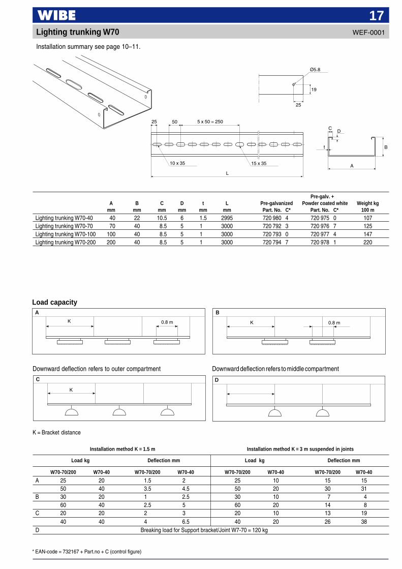
17Lighting trunking W70
Installation summary see page 10–11.
Load capacity
Downward deflection refers to outer compartment Downward deflection refers to middle compartment
K 0.8 m
K
Installation method K = 1.5 m Installation method K = 3 m suspended in joints
Load kg Deflection mm Load kg Deflection mm
W70-70/200 W70-40 W70-70/200 W70-40 W70-70/200 W70-40 W70-70/200 W70-40
A 25 20 1.5 2 25 10 15 1550 40 3.5 4.5 50 20 30 31
B 30 20 1 2.5 30 10 7 460 40 2.5 5 60 20 14 8
C 20 20 2 3 20 10 13 1940 40 4 6.5 40 20 26 38
D Breaking load for Support bracket/Joint W7-70 = 120 kg
Pre-galv. +A B C D t L Pre-galvanized Powder coated white Weight kg
mm mm mm mm mm mm Part. No. C* Part. No. C* 100 m
Lighting trunking W70-40 40 22 10.5 6 1.5 2995 720 980 4 720 975 0 107Lighting trunking W70-70 70 40 8.5 5 1 3000 720 792 3 720 976 7 125Lighting trunking W70-100 100 40 8.5 5 1 3000 720 793 0 720 977 4 147Lighting trunking W70-200 200 40 8.5 5 1 3000 720 794 7 720 978 1 220
K = Bracket distance
WEF-0001
K 0.8 m
CD
Bt
10 x 35 15 x 35
5 x 50 = 2505025
L
A
19
25
Ø5.8
* EAN-code = 732167 + Part.no + C (control figure)
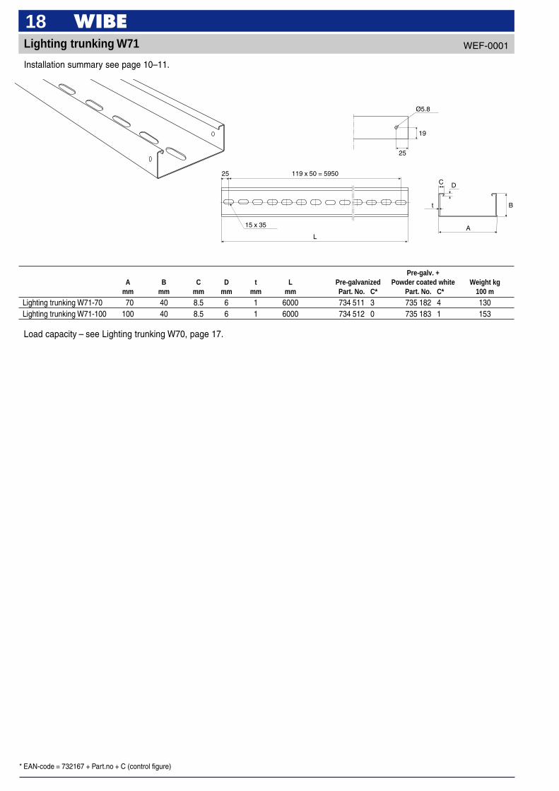
18Lighting trunking W71
Installation summary see page 10–11.
Pre-galv. +A B C D t L Pre-galvanized Powder coated white Weight kg
mm mm mm mm mm mm Part. No. C* Part. No. C* 100 m
Lighting trunking W71-70 70 40 8.5 6 1 6000 734 511 3 735 182 4 130Lighting trunking W71-100 100 40 8.5 6 1 6000 734 512 0 735 183 1 153
WEF-0001
A
B
DC
t
119 x 50 = 5950
15 x 35
25
L
25
19
Ø5.8
Load capacity – see Lighting trunking W70, page 17.
* EAN-code = 732167 + Part.no + C (control figure)
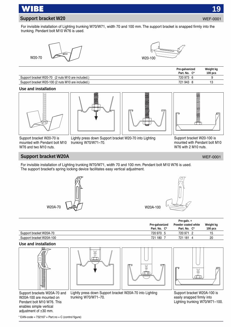
19Support bracket W20
For invisible installation of Lighting trunking W70/W71, width 70 and 100 mm. The support bracket is snapped firmly into thetrunking. Pendant bolt M10 W76 is used.
W20-70 W20-100
Use and installation
Support brackets W20A-70 andW20A-100 are mounted onPendant bolt M10 W76. Thisenables simple verticaladjustment of ±30 mm.
Lightly press down Support bracket W20A-70 into Lightingtrunking W70/W71–70.
Support bracket W20A-100 iseasily snapped firmly intoLighting trunking W70/W71–100.
Use and installation
Support bracket W20-70 ismounted with Pendant bolt M10W76 and two M10 nuts.
Lightly press down Support bracket W20-70 into Lightingtrunking W70/W71–70.
Support bracket W20-100 ismounted with Pendant bolt M10W76 with 2 M10 nuts.
Pre-galvanized Weight kgPart. No. C* 100 pcs
Support bracket W20-70 (2 nuts M10 are included.) 720 973 6 9Support bracket W20-100 (2 nuts M10 are included.) 721 943 8 13
Pre-galv. +Pre-galvanized Powder coated white Weight kgPart. No. C* Part. No. C* 100 pcs
Support bracket W20A-70 720 970 5 720 971 2 15Support bracket W20A-100 721 180 7 721 181 4 20
W20A-100W20A-70
Support bracket W20A
For invisible installation of Lighting trunking W70/W71, width 70 and 100 mm. Pendant bolt M10 W76 is used.The support bracket's spring locking device facilitates easy vertical adjustment.
WEF-0001
WEF-0001

* EAN-code = 732167 + Part.no + C (control figure)
20WEF-0001Support bracket W1940
A
A
Width 100–400
Width 500–600
Alternatively, Tray W1 and W3with widths 500 and 600 can beinstalled with suitable Supportbracket W1940, with Threadedrod M10 W76 and Tube pendantattachment W73.
W36
W73
Alternatively, Tray W1 and W3with widths 500 and 600 can beinstalled with suitable Supportbracket W1940, with Pendantrail W32, Pendant attachmentW21 and Screw set W37.
W37W21
W32
Tray W1 and W3 can bemounted on suitable Supportbracket W1940 and 2 Endbracket WN17 as pendant. Theend brackets are joined with 2Screw sets 22S and can beadjusted in height. The pendantcan be mounted in the supportbracket with 1 Screw set W36.
Alternatively, Tray W1 and W3with widths 500 and 600 can beinstalled with suitable Supportbracket W1940, with PendantM10 and 2 M10 Nuts.
Threaded rodM10 W76
2 nuts M10
For installation inside Cable trays W1 and W3.
Width 500–600
Width 100–400
Use and installation
Support bracket W1940mounted with Ceiling bracket 5,Pendant/Fixing rail 24/34 andAngle bracket W8S. Screw set22S must be used. For cabletrays with width 500 and 600.
Support bracket W1940mounted on Vertical piece 2 andCeiling bracket 5. Screw set 22Smust be used. For cable trayswith width 500 and 600.
Support bracket W1940 can bemounted with Vertical piece 2 +Pendant joint 2J + Pendant/Fixing rail 24/34 and Ceilingbracket 5. Screw set 22S mustbe used. For cable trays withwidth 500 and 600.
W31
W32
W37
W36W21
Tray W1 and W3 with widths of200 to 400 are mounted withsuitable Support bracket W1940and Pendant rail W32, Pendantattachment W21 and Screw setW37.
Pre-galv. +A Pre-galvanized Hot dip galv. Powder coated white Weight kg
mm Part. No. C* Part. No. C* Part. No. C* 100 pcs
Support bracket W1940-100 90 718 711 9 734 452 9 720 501 1 11Support bracket W1940-200 190 734 401 7 734 453 6 720 502 8 22Support bracket W1940-300 289 734 402 4 734 454 3 720 503 5 50Support bracket W1940-400 389 734 403 1 734 455 0 720 504 2 68Support bracket W1940-500 497 720 998 9 734 456 7 723 894 1 81Support bracket W1940-600 597 723 185 0 734 457 4 723 895 8 99
Threaded rodM10 W76
* EAN-code = 732167 + Part.no + C (control figure)
21
E Ø7
15 27
Ø11 x 22
B
C
D
Ø9
A
30
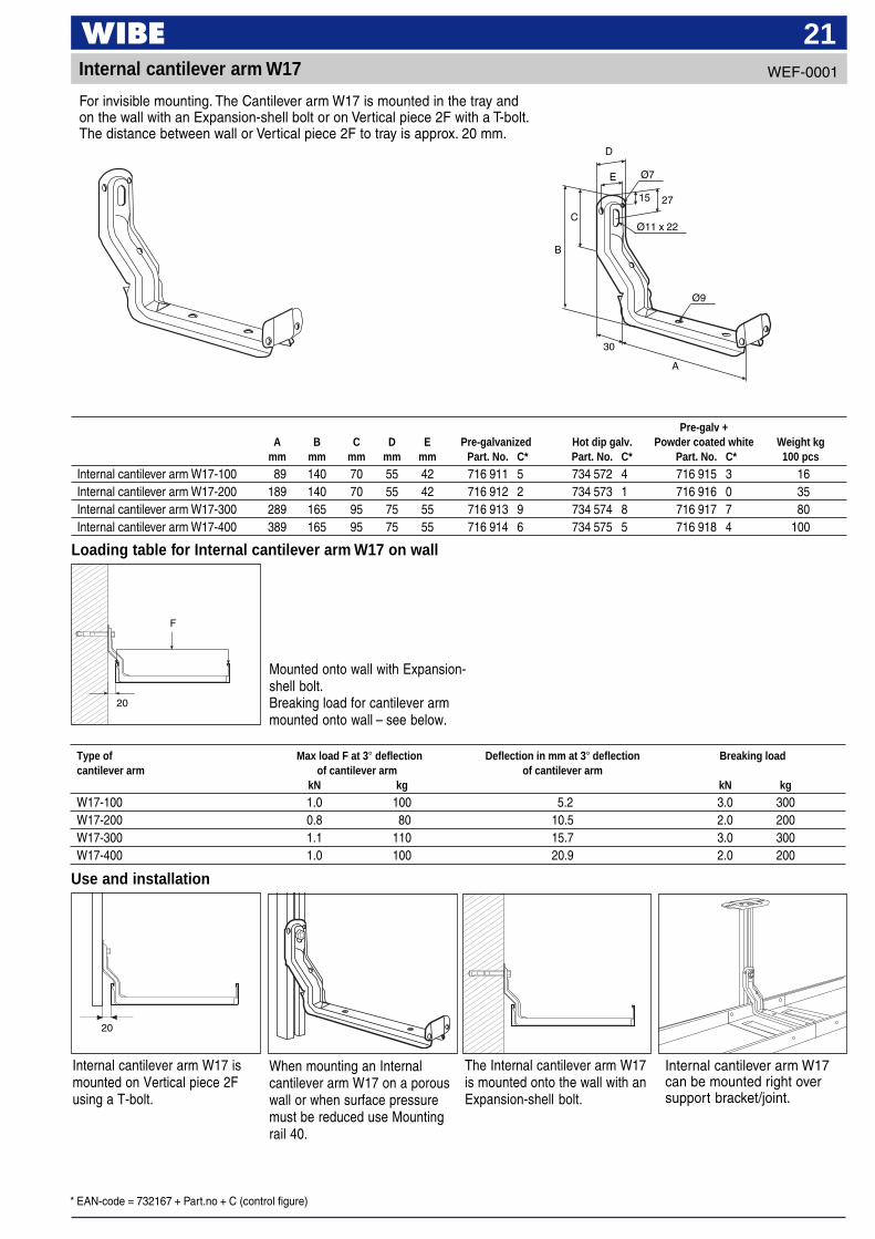
Internal cantilever arm W17
For invisible mounting. The Cantilever arm W17 is mounted in the tray andon the wall with an Expansion-shell bolt or on Vertical piece 2F with a T-bolt.The distance between wall or Vertical piece 2F to tray is approx. 20 mm.
Type of Max load F at 3° deflection Deflection in mm at 3° deflection Breaking loadcantilever arm of cantilever arm of cantilever arm
kN kg kN kg
W17-100 1.0 100 5.2 3.0 300W17-200 0.8 80 10.5 2.0 200W17-300 1.1 110 15.7 3.0 300W17-400 1.0 100 20.9 2.0 200
Use and installation
Internal cantilever arm W17 ismounted on Vertical piece 2Fusing a T-bolt.
20
When mounting an Internalcantilever arm W17 on a porouswall or when surface pressuremust be reduced use Mountingrail 40.
The Internal cantilever arm W17is mounted onto the wall with anExpansion-shell bolt.
Internal cantilever arm W17can be mounted right oversupport bracket/joint.
Loading table for Internal cantilever arm W17 on wall
F
Mounted onto wall with Expansion-shell bolt.Breaking load for cantilever armmounted onto wall – see below.
Pre-galv +A B C D E Pre-galvanized Hot dip galv. Powder coated white Weight kg
mm mm mm mm mm Part. No. C* Part. No. C* Part. No. C* 100 pcs
Internal cantilever arm W17-100 89 140 70 55 42 716 911 5 734 572 4 716 915 3 16Internal cantilever arm W17-200 189 140 70 55 42 716 912 2 734 573 1 716 916 0 35Internal cantilever arm W17-300 289 165 95 75 55 716 913 9 734 574 8 716 917 7 80Internal cantilever arm W17-400 389 165 95 75 55 716 914 6 734 575 5 716 918 4 100
20
WEF-0001
* EAN-code = 732167 + Part.no + C (control figure)
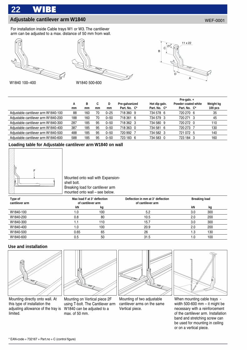
22Adjustable cantilever arm W1840
Type of Max load F at 3° deflection Deflection in mm at 3° deflection Breaking loadcantilever arm of cantilever arm of cantilever arm
kN kg kN kg
W1840-100 1.0 100 5.2 3.0 300W1840-200 0.8 80 10.5 2.0 200W1840-300 1.1 110 15.7 3.0 300W1840-400 1.0 100 20.9 2.0 200W1840-500 0.65 65 26 1.3 130W1840-600 0.5 50 31.5 1.0 100
Loading table for Adjustable cantilever arm W1840 on wall
Use and installation
BC
2711 x 22
DA
F
Mounted onto wall with Expansion-shell bolt.Breaking load for cantilever armmounted onto wall – see below.
Mounting directly onto wall. Atthis type of installation theadjusting allowance of the tray islimited.
Mounting on Vertical piece 2Fusing T-bolt. The Cantilever armW1840 can be adjusted to amax. of 50 mm.
Mounting of two adjustablecantilever arms on the sameVertical piece.
When mounting cable trays -width 500-600 mm – it might benecessary with a reinforcementof the cantilever arm. Installationband and stretching screw canbe used for mounting in ceilingor on a vertical piece.
Pre-galv. +A B C D Pre-galvanized Hot dip galv. Powder coated white Weight kg
mm mm mm mm Part. No. C* Part. No. C* Part. No. C* 100 pcs
Adjustable cantilever arm W1840-100 88 160 70 0–25 718 360 9 734 578 6 720 270 6 35Adjustable cantilever arm W1840-200 188 160 70 0–50 718 361 6 734 579 3 720 271 3 45Adjustable cantilever arm W1840-300 287 185 95 0–50 718 362 3 734 580 9 720 272 0 110Adjustable cantilever arm W1840-400 387 185 95 0–50 718 363 0 734 581 6 720 273 7 130Adjustable cantilever arm W1840-500 488 185 95 0–50 720 992 7 734 582 3 721 072 5 140Adjustable cantilever arm W1840-600 588 185 95 0–50 723 183 6 734 583 0 723 184 3 160
W1840 100–400 W1840 500-600
For installation inside Cable trays W1 or W3. The cantileverarm can be adjusted to a max. distance of 50 mm from wall.
WEF-0001
* EAN-code = 732167 + Part.no + C (control figure)
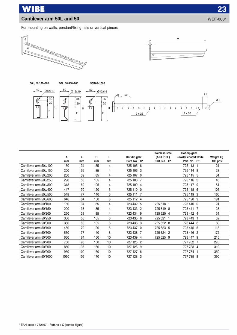
23
For mounting on walls, pendant/fixing rails or vertical pieces.
AT
50L, 50/100–300 50L, 50/400–600 50/700–1000
25
Ø12x19
20
20
F
H
Ø12x19
20
F
H
Ø12x19
25
20
F
H
28 50
9 x 26 9 x 36
21
Ø 5
40 50 50
Stainless steel Hot dip galv. +A F H T Hot dip galv. (AISI 316L) Powder coated white Weight kg
mm mm mm mm Part. No. C* Part. No. C* Part. No. C* 100 pcs
Cantilever arm 50L/100 150 34 85 4 725 105 6 725 113 1 24Cantilever arm 50L/150 200 36 85 4 725 106 3 725 114 8 28Cantilever arm 50L/200 250 39 85 4 725 107 0 725 115 5 34Cantilever arm 50L/250 298 56 105 4 725 108 7 725 116 2 46Cantilever arm 50L/300 348 60 105 4 725 109 4 725 117 9 54Cantilever arm 50L/400 447 70 120 5 725 110 0 725 118 6 103Cantilever arm 50L/500 548 77 140 6 725 111 7 725 119 3 160Cantilever arm 50L/600 646 84 150 6 725 112 4 725 120 9 191Cantilever arm 50/100 150 34 85 4 723 432 5 725 618 1 723 440 0 24Cantilever arm 50/150 200 36 85 4 723 433 2 725 619 8 723 441 7 28Cantilever arm 50/200 250 39 85 4 723 434 9 725 620 4 723 442 4 34Cantilever arm 50/250 300 56 105 6 723 435 6 725 621 1 723 443 1 52Cantilever arm 50/300 350 60 105 6 723 436 3 725 622 8 723 444 8 60Cantilever arm 50/400 450 70 120 8 723 437 0 725 623 5 723 445 5 118Cantilever arm 50/500 550 77 140 8 723 438 7 725 624 2 723 446 2 172Cantilever arm 50/600 650 84 150 10 723 439 4 725 625 9 723 447 9 215Cantilever arm 50/700 750 90 150 10 727 125 2 727 782 7 270Cantilever arm 50/800 850 95 160 10 727 126 9 727 783 4 310Cantilever arm 50/900 950 100 160 10 727 127 6 727 784 1 350Cantilever arm 50/1000 1050 105 170 10 727 128 3 727 785 8 390
Cantilever arm 50L and 50 WEF-0001
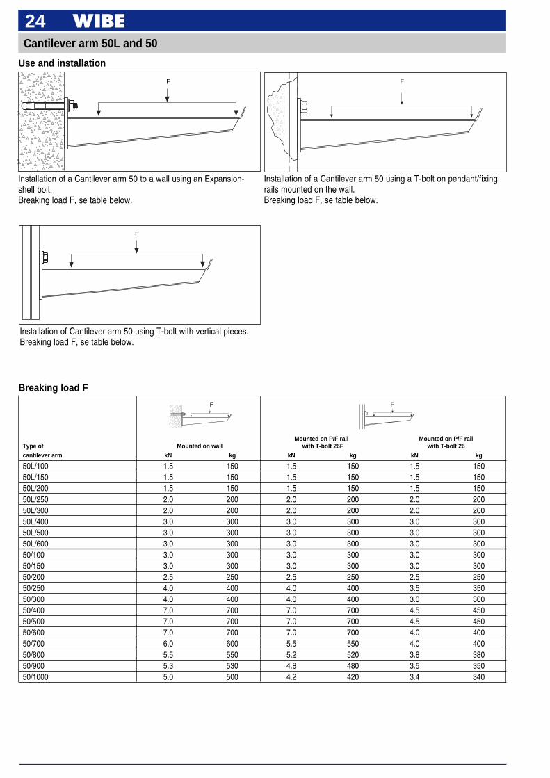
24Cantilever arm 50L and 50
Use and installation
Installation of a Cantilever arm 50 to a wall using an Expansion-shell bolt.Breaking load F, se table below.
Installation of a Cantilever arm 50 using a T-bolt on pendant/fixingrails mounted on the wall.Breaking load F, se table below.
F
Mounted on P/F rail Mounted on P/F railType of Mounted on wall with T-bolt 26F with T-bolt 26cantilever arm kN kg kN kg kN kg
50L/100 1.5 150 1.5 150 1.5 15050L/150 1.5 150 1.5 150 1.5 15050L/200 1.5 150 1.5 150 1.5 15050L/250 2.0 200 2.0 200 2.0 20050L/300 2.0 200 2.0 200 2.0 20050L/400 3.0 300 3.0 300 3.0 30050L/500 3.0 300 3.0 300 3.0 30050L/600 3.0 300 3.0 300 3.0 30050/100 3.0 300 3.0 300 3.0 30050/150 3.0 300 3.0 300 3.0 30050/200 2.5 250 2.5 250 2.5 25050/250 4.0 400 4.0 400 3.5 35050/300 4.0 400 4.0 400 3.0 30050/400 7.0 700 7.0 700 4.5 45050/500 7.0 700 7.0 700 4.5 45050/600 7.0 700 7.0 700 4.0 40050/700 6.0 600 5.5 550 4.0 40050/800 5.5 550 5.2 520 3.8 38050/900 5.3 530 4.8 480 3.5 35050/1000 5.0 500 4.2 420 3.4 340
Breaking load F
Installation of Cantilever arm 50 using T-bolt with vertical pieces.Breaking load F, se table below.
F F
F
F
* EAN-code = 732167 + Part.no + C (control figure)
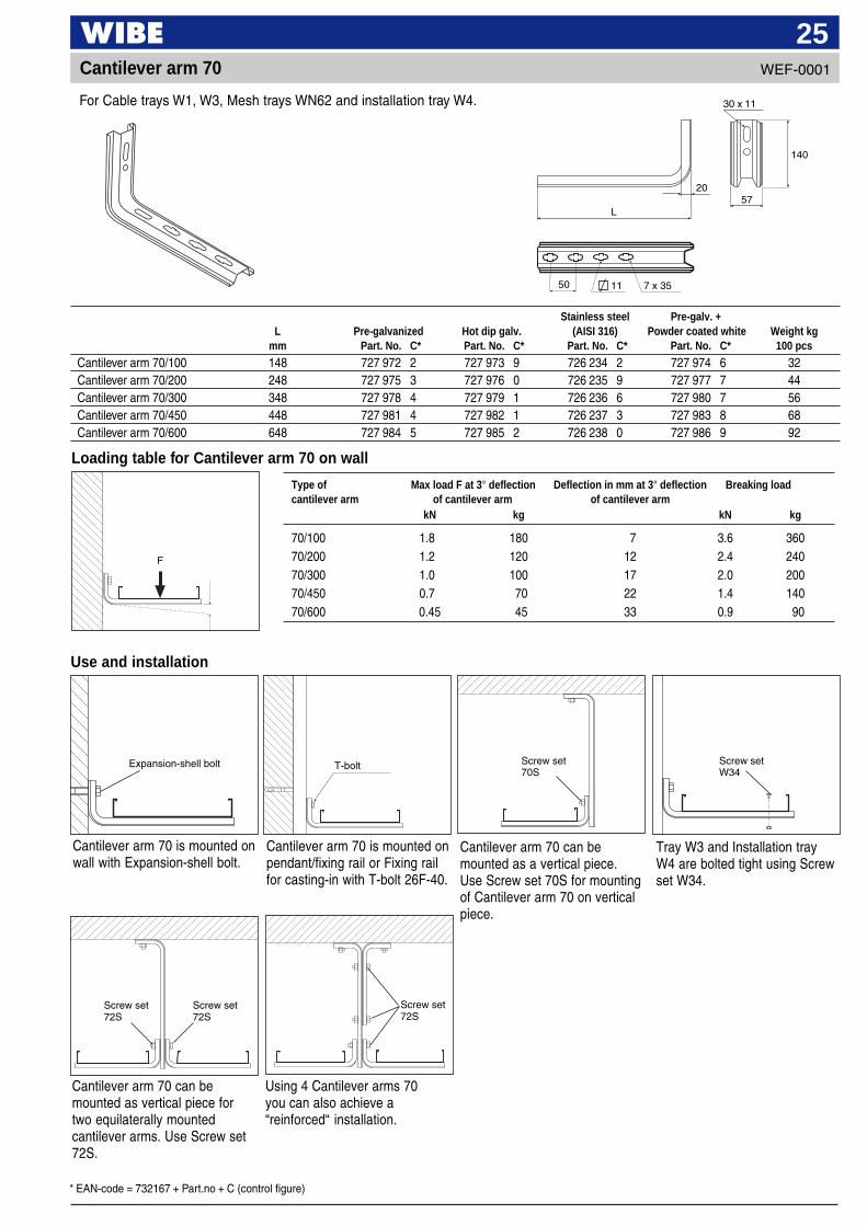
25
Loading table for Cantilever arm 70 on wall
Cantilever arm 70 is mounted onpendant/fixing rail or Fixing railfor casting-in with T-bolt 26F-40.
Cantilever arm 70 can bemounted as a vertical piece.Use Screw set 70S for mountingof Cantilever arm 70 on verticalpiece.
Tray W3 and Installation trayW4 are bolted tight using Screwset W34.
Cantilever arm 70 is mounted onwall with Expansion-shell bolt.
Use and installation
Cantilever arm 70
Cantilever arm 70 can bemounted as vertical piece fortwo equilaterally mountedcantilever arms. Use Screw set72S.
Using 4 Cantilever arms 70you can also achieve a“reinforced“ installation.
T-bolt
Type of Max load F at 3° deflection Deflection in mm at 3° deflection Breaking loadcantilever arm of cantilever arm of cantilever arm
kN kg kN kg
70/100 1.8 180 7 3.6 36070/200 1.2 120 12 2.4 24070/300 1.0 100 17 2.0 20070/450 0.7 70 22 1.4 14070/600 0.45 45 33 0.9 90
Stainless steel Pre-galv. +L Pre-galvanized Hot dip galv. (AISI 316) Powder coated white Weight kg
mm Part. No. C* Part. No. C* Part. No. C* Part. No. C* 100 pcs
Cantilever arm 70/100 148 727 972 2 727 973 9 726 234 2 727 974 6 32Cantilever arm 70/200 248 727 975 3 727 976 0 726 235 9 727 977 7 44Cantilever arm 70/300 348 727 978 4 727 979 1 726 236 6 727 980 7 56Cantilever arm 70/450 448 727 981 4 727 982 1 726 237 3 727 983 8 68Cantilever arm 70/600 648 727 984 5 727 985 2 726 238 0 727 986 9 92
For Cable trays W1, W3, Mesh trays WN62 and installation tray W4.
F
WEF-0001
Screw set70S
Screw setW34
Screw set72S
Screw set72S
Screw set72S
Expansion-shell bolt
30 x 11
57
140
50
L
11 7 x 35
20
* EAN-code = 732167 + Part.no + C (control figure)
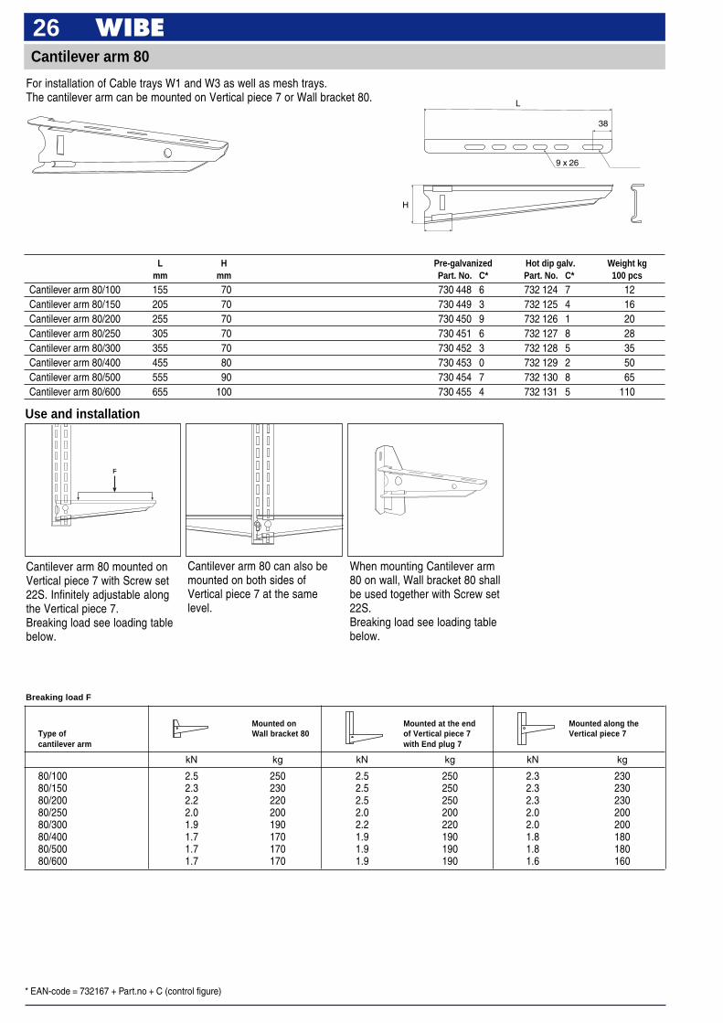
26Cantilever arm 80
Breaking load F
Use and installation
L H Pre-galvanized Hot dip galv. Weight kgmm mm Part. No. C* Part. No. C* 100 pcs
Cantilever arm 80/100 155 70 730 448 6 732 124 7 12Cantilever arm 80/150 205 70 730 449 3 732 125 4 16Cantilever arm 80/200 255 70 730 450 9 732 126 1 20Cantilever arm 80/250 305 70 730 451 6 732 127 8 28Cantilever arm 80/300 355 70 730 452 3 732 128 5 35Cantilever arm 80/400 455 80 730 453 0 732 129 2 50Cantilever arm 80/500 555 90 730 454 7 732 130 8 65Cantilever arm 80/600 655 100 730 455 4 732 131 5 110
F
Cantilever arm 80 mounted onVertical piece 7 with Screw set22S. Infinitely adjustable alongthe Vertical piece 7.Breaking load see loading tablebelow.
When mounting Cantilever arm80 on wall, Wall bracket 80 shallbe used together with Screw set22S.Breaking load see loading tablebelow.
Cantilever arm 80 can also bemounted on both sides ofVertical piece 7 at the samelevel.
Mounted on Mounted at the end Mounted along theType of Wall bracket 80 of Vertical piece 7 Vertical piece 7cantilever arm with End plug 7
kN kg kN kg kN kg
80/100 2.5 250 2.5 250 2.3 23080/150 2.3 230 2.5 250 2.3 23080/200 2.2 220 2.5 250 2.3 23080/250 2.0 200 2.0 200 2.0 20080/300 1.9 190 2.2 220 2.0 20080/400 1.7 170 1.9 190 1.8 18080/500 1.7 170 1.9 190 1.8 18080/600 1.7 170 1.9 190 1.6 160
For installation of Cable trays W1 and W3 as well as mesh trays.The cantilever arm can be mounted on Vertical piece 7 or Wall bracket 80.
H
L
38
9 x 26
* EAN-code = 732167 + Part.no + C (control figure)
27
9 x 9
12 x 19
155
43 55
2045
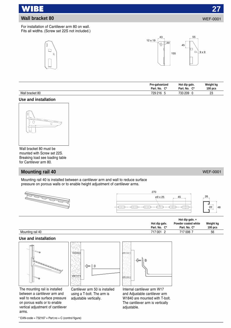
Wall bracket 80
Wall bracket 80 must bemounted with Screw set 22S.Breaking load see loading tablefor Cantilever arm 80.
Use and installation
Mounting rail 40
270
22 48
ø9 x 25 45 26
Use and installation
The mounting rail is installedbetween a cantilever arm andwall to reduce surface pressureon porous walls or to enablevertical adjustment of cantileverarms.
Cantilever arm 50 is installedusing a T-bolt. The arm isadjustable vertically.
Internal cantilever arm W17and Adjustable cantilever armW1840 are mounted with T-bolt.The cantilever arm is verticallyadjustable.
Pre-galvanized Hot dip galv. Weight kgPart. No. C* Part. No. C* 100 pcs
Wall bracket 80 729 216 5 733 209 0 23
Hot dip galv. +Hot dip galv. Powder coated white Weight kgPart. No. C* Part. No. C* 100 pcs
Mounting rail 40 717 001 2 717 006 7 56
For installation of Cantilever arm 80 on wall.Fits all widths. (Screw set 22S not included.)
Mounting rail 40 is installed between a cantilever arm and wall to reduce surfacepressure on porous walls or to enable height adjustment of cantilever arms.
WEF-0001
WEF-0001
* EAN-code = 732167 + Part.no + C (control figure)
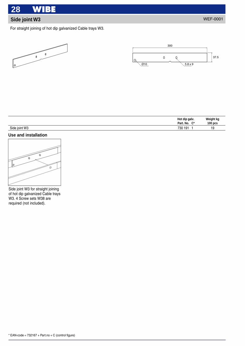
28Side joint W3
5.8 x 9Ø10
300
37.5
Use and installation
Side joint W3 for straight joiningof hot dip galvanized Cable traysW3. 4 Screw sets W38 arerequired (not included).
Hot dip galv. Weight kgPart. No. C* 100 pcs
Side joint W3 730 191 1 19
For straight joining of hot dip galvanized Cable trays W3.
WEF-0001
* EAN-code = 732167 + Part.no + C (control figure)
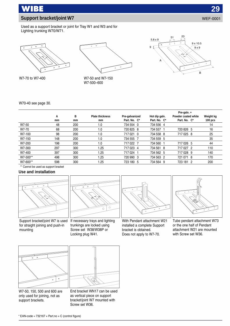
29Support bracket/joint W7
Use and installation
W7-70 to W7-400
5.8 x 9
9 9 x 9
2351
B
9 x 10.5
A
Support bracket/joint W7 is usedfor straight joining and push-inmounting
If necessary trays and lightingtrunkings are locked usingScrew set W38/W38P orLocking plug W41.
With Pendant attachment W21installed a complete Supportbracket is obtained.Does not apply to W7-70.
Tube pendant attachment W73or the one half of Pendantattachment W21 are mountedwith Screw set W36.
Pre-galv. +A B Plate thickness Pre-galvanized Hot dip galv. Powder coated white Weight kg
mm mm mm Part. No. C* Part. No. C* Part. No. C* 100 pcs
W7-50 48 200 1.0 734 554 0 734 556 4 14W7-70 68 200 1.0 720 825 8 734 557 1 720 826 5 16W7-100 98 200 1.0 717 021 0 734 558 8 717 025 8 25W7-150 148 200 1.0 734 555 7 734 559 5 35W7-200 198 200 1.0 717 022 7 734 560 1 717 026 5 44W7-300 297 300 1.25 717 023 4 734 561 8 717 027 2 110W7-400 397 300 1.25 717 024 1 734 562 5 717 028 9 140W7-500** 498 300 1.25 720 990 3 734 563 2 721 071 8 170W7-600** 598 300 1.25 723 180 5 734 564 9 723 181 2 200** Cannot be used as support bracket
Used as a support bracket or joint for Tray W1 and W3 and forLighting trunking W70/W71.
W7-50, 150, 500 and 600 areonly used for joining, not assupport brackets.
End bracket WN17 can be usedas vertical piece on supportbracket/joint W7 mounted withScrew set W36.
WEF-0001
W7-50 and W7-150W7-500–600
W70-40 see page 30.

* EAN-code = 732167 + Part.no + C (control figure)
30
40 x 9
BA
Joint W7-40
Used for joining Lighting trunking W70-40. The Joint W7-40 is locked usingScrew set W36 at the bottom of the trunking.
Pre-galv. +A B Plate thickness Pre-galvanized Powder coated white Weight kg
mm mm mm Part. No. C* Part. No. C* 100 pcs
Joint W7-40 36 180 1.5 718 480 4 718 481 1 13
The Joint W7-40 is locked usingScrew set W36 at the bottom ofthe trunking.
Use and installation
WEF-0001
* EAN-code = 732167 + Part.no + C (control figure)
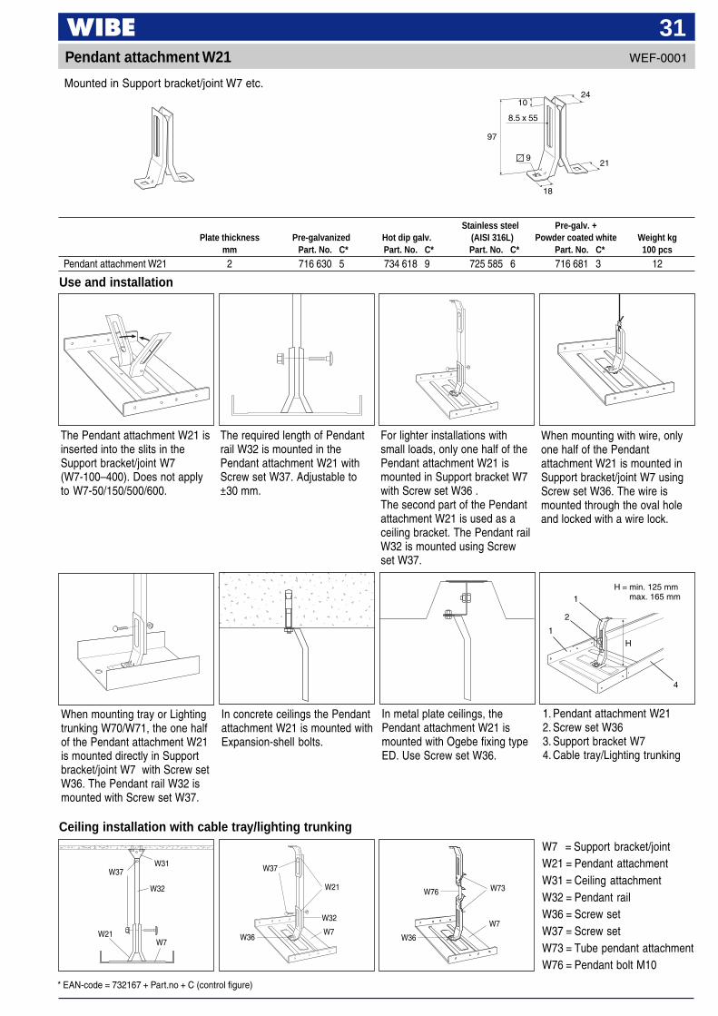
31Pendant attachment W21
Ceiling installation with cable tray/lighting trunking
W31
W32
W37 W37
W21
W32
W73W76
W7 = Support bracket/jointW21 = Pendant attachmentW31 = Ceiling attachmentW32 = Pendant railW36 = Screw setW37 = Screw setW73 = Tube pendant attachmentW76 = Pendant bolt M10
W7W21
W7W36
W7W36
When mounting tray or Lightingtrunking W70/W71, the one halfof the Pendant attachment W21is mounted directly in Supportbracket/joint W7 with Screw setW36. The Pendant rail W32 ismounted with Screw set W37.
In concrete ceilings the Pendantattachment W21 is mounted withExpansion-shell bolts.
In metal plate ceilings, thePendant attachment W21 ismounted with Ogebe fixing typeED. Use Screw set W36.
1. Pendant attachment W212. Screw set W363. Support bracket W74. Cable tray/Lighting trunking
H = min. 125 mmmax. 165 mm1
2
4
1
Stainless steel Pre-galv. +Plate thickness Pre-galvanized Hot dip galv. (AISI 316L) Powder coated white Weight kg
mm Part. No. C* Part. No. C* Part. No. C* Part. No. C* 100 pcs
Pendant attachment W21 2 716 630 5 734 618 9 725 585 6 716 681 3 12
Use and installation
The Pendant attachment W21 isinserted into the slits in theSupport bracket/joint W7(W7-100–400). Does not applyto W7-50/150/500/600.
The required length of Pendantrail W32 is mounted in thePendant attachment W21 withScrew set W37. Adjustable to±30 mm.
For lighter installations withsmall loads, only one half of thePendant attachment W21 ismounted in Support bracket W7with Screw set W36 .The second part of the Pendantattachment W21 is used as aceiling bracket. The Pendant railW32 is mounted using Screwset W37.
When mounting with wire, onlyone half of the Pendantattachment W21 is mounted inSupport bracket/joint W7 usingScrew set W36. The wire ismounted through the oval holeand locked with a wire lock.
Mounted in Support bracket/joint W7 etc.
WEF-0001
H
8.5 x 55
21
1024
18
97
9
* EAN-code = 732167 + Part.no + C (control figure)
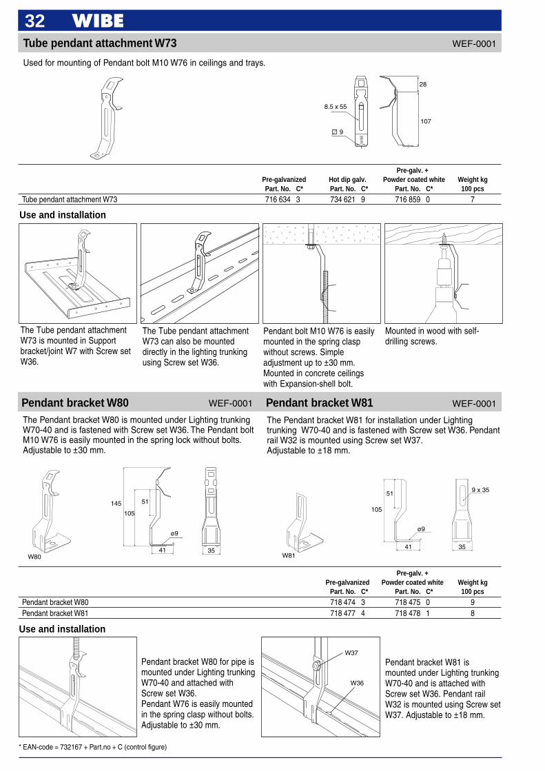
32Tube pendant attachment W73
Used for mounting of Pendant bolt M10 W76 in ceilings and trays.
8.5 x 55
28
107
9
Use and installation
Pendant bolt M10 W76 is easilymounted in the spring claspwithout screws. Simpleadjustment up to ±30 mm.Mounted in concrete ceilingswith Expansion-shell bolt.
Mounted in wood with self-drilling screws.
The Tube pendant attachmentW73 can also be mounteddirectly in the lighting trunkingusing Screw set W36.
The Tube pendant attachmentW73 is mounted in Supportbracket/joint W7 with Screw setW36.
Use and installation
Pendant bracket W80 for pipe ismounted under Lighting trunkingW70-40 and attached withScrew set W36.Pendant W76 is easily mountedin the spring clasp without bolts.Adjustable to ±30 mm.
Pendant bracket W81 ismounted under Lighting trunkingW70-40 and is attached withScrew set W36. Pendant railW32 is mounted using Screw setW37. Adjustable to ±18 mm.
Pre-galv. +Pre-galvanized Hot dip galv. Powder coated white Weight kgPart. No. C* Part. No. C* Part. No. C* 100 pcs
Tube pendant attachment W73 716 634 3 734 621 9 716 859 0 7
Pre-galv. +Pre-galvanized Powder coated white Weight kg
Part. No. C* Part. No. C* 100 pcs
Pendant bracket W80 718 474 3 718 475 0 9Pendant bracket W81 718 477 4 718 478 1 8
Pendant bracket W80 Pendant bracket W81The Pendant bracket W80 is mounted under Lighting trunkingW70-40 and is fastened with Screw set W36. The Pendant boltM10 W76 is easily mounted in the spring lock without bolts.Adjustable to ±30 mm.
The Pendant bracket W81 for installation under Lightingtrunking W70-40 and is fastened with Screw set W36. Pendantrail W32 is mounted using Screw set W37.Adjustable to ±18 mm.
WEF-0001
WEF-0001WEF-0001
ø9
145 51
105
41 35W80
41
ø9
105
51
35
9 x 35
W81
W37
W36
* EAN-code = 732167 + Part.no + C (control figure)
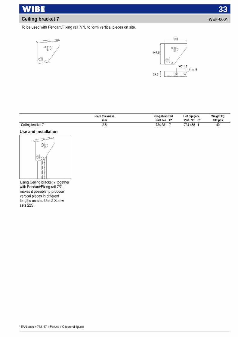
33WEF-0001Ceiling bracket 7
Plate thickness Pre-galvanized Hot dip galv. Weight kgmm Part. No. C* Part. No. C* 100 pcs
Ceiling bracket 7 2.5 734 331 7 734 458 1 40
160
147.5
60 15
39.5
11 x 18
Use and installation
Using Ceiling bracket 7 togetherwith Pendant/Fixing rail 7/7Lmakes it possible to producevertical pieces in differentlengths on site. Use 2 Screwsets 22S.
To be used with Pendant/Fixing rail 7/7L to form vertical pieces on site.
* EAN-code = 732167 + Part.no + C (control figure)
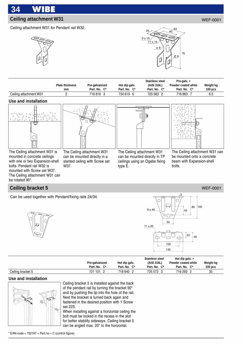
34WEF-0001Ceiling attachment W31
Use and installation
The Ceiling attachment W31can be mounted directly in TPceilings using an Ogebe fixingtype E.
The Ceiling attachment W31 canbe mounted onto a concretebeam with Expansion-shellbolts.
The Ceiling attachment W31can be mounted directly in aslanted ceiling with Screw setW37.
The Ceiling attachment W31 ismounted in concrete ceilingswith one or two Expansion-shellbolts. Pendant rail W32 ismounted with Screw set W37.The Ceiling attachment W31 canbe rotated 90°.
40
1009 x 40
50
85
11 x 20
135
22
100
3
43
Use and installationCeiling bracket 5 is installed against the backof the pendant rail by turning the bracket 90°and by pushing the lip into the hole of the rail.Next the bracket is turned back again andfastened in the desired position with 1 Screwset 22S.When installing against a horizontal ceiling thebolt must be locked in the recess in the slotfor better stability sideways. Ceiling bracket 5can be angled max. 20° to the horizontal.
Ceiling bracket 5
Ceiling attachment W31 for Pendant rail W32.
Stainless steel Pre-galv. +Plate thickness Pre-galvanized Hot dip galv. (AISI 316L) Powder coated white Weight kg
mm Part. No. C* Part. No. C* Part. No. C* Part. No. C* 100 pcs
Ceiling attachment W31 2 716 816 3 734 619 6 725 583 2 716 863 7 6.5
4064
25
9 x 1511 x 15
ø 9
709
Can be used together with Pendant/fixing rails 24/34.
Stainless steel Hot dip galv. +Pre-galvanized Hot dip galv. (AISI 316L) Powder coated white Weight kg
Part. No. C* Part. No. C* Part. No. C* Part. No. C* 100 pcs
Ceiling bracket 5 721 101 2 718 640 2 725 573 3 716 293 2 35
WEF-0001
* EAN-code = 732167 + Part.no + C (control figure)
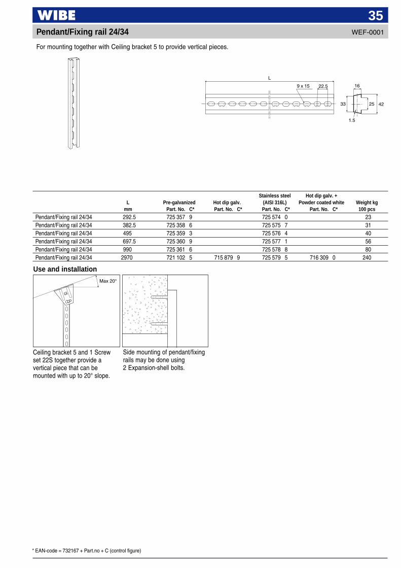
35Pendant/Fixing rail 24/34 WEF-0001
4233
L
9 x 15 22.5 16
25
1.5
Max 20°
Use and installation
Ceiling bracket 5 and 1 Screwset 22S together provide avertical piece that can bemounted with up to 20° slope.
Stainless steel Hot dip galv. +L Pre-galvanized Hot dip galv. (AISI 316L) Powder coated white Weight kg
mm Part. No. C* Part. No. C* Part. No. C* Part. No. C* 100 pcs
Pendant/Fixing rail 24/34 292.5 725 357 9 725 574 0 23Pendant/Fixing rail 24/34 382.5 725 358 6 725 575 7 31Pendant/Fixing rail 24/34 495 725 359 3 725 576 4 40Pendant/Fixing rail 24/34 697.5 725 360 9 725 577 1 56Pendant/Fixing rail 24/34 990 725 361 6 725 578 8 80Pendant/Fixing rail 24/34 2970 721 102 5 715 879 9 725 579 5 716 309 0 240
Side mounting of pendant/fixingrails may be done using2 Expansion-shell bolts.
For mounting together with Ceiling bracket 5 to provide vertical pieces.
* EAN-code = 732167 + Part.no + C (control figure)
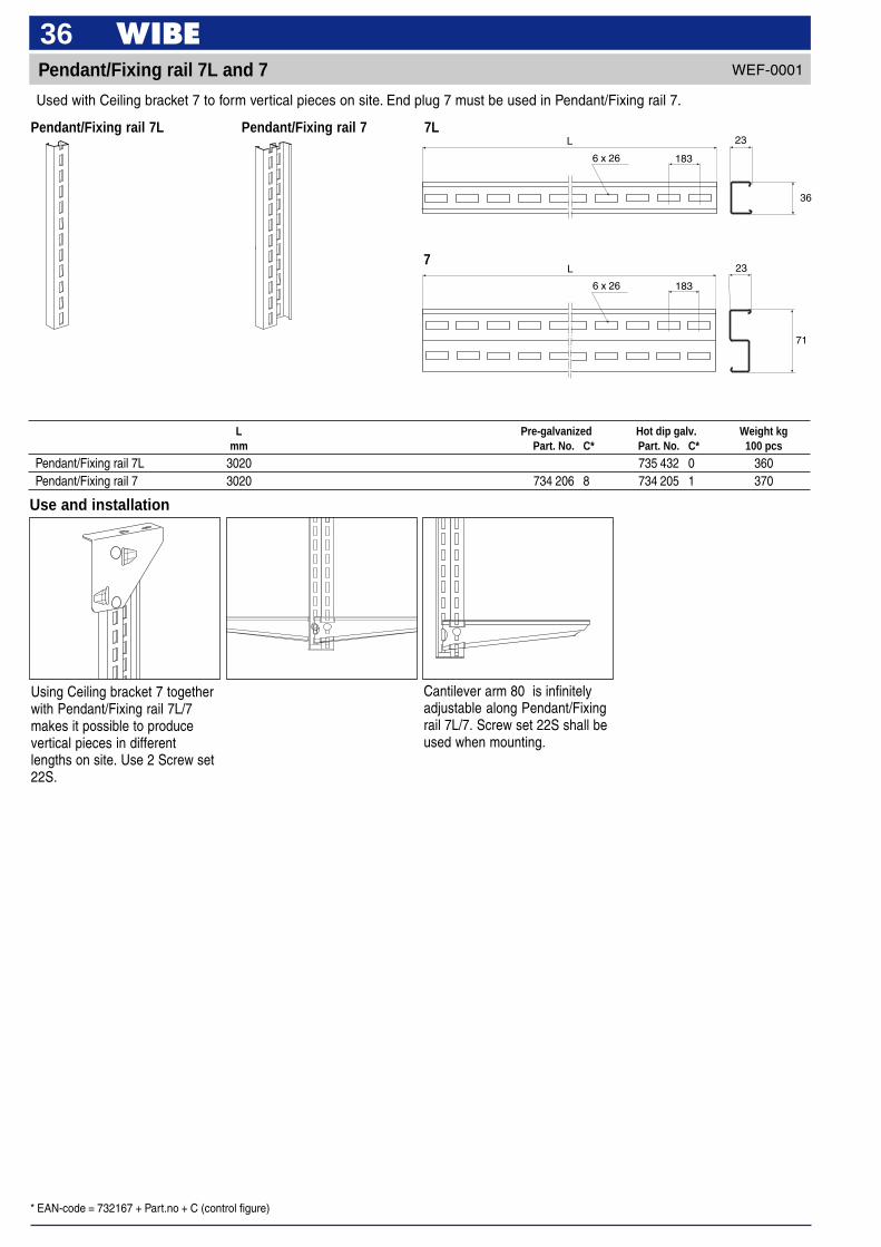
36Pendant/Fixing rail 7L and 7
71
23
6 x 26 183
L
Used with Ceiling bracket 7 to form vertical pieces on site. End plug 7 must be used in Pendant/Fixing rail 7.
WEF-0001
Using Ceiling bracket 7 togetherwith Pendant/Fixing rail 7L/7makes it possible to producevertical pieces in differentlengths on site. Use 2 Screw set22S.
Use and installation
L Pre-galvanized Hot dip galv. Weight kgmm Part. No. C* Part. No. C* 100 pcs
Pendant/Fixing rail 7L 3020 735 432 0 360Pendant/Fixing rail 7 3020 734 206 8 734 205 1 370
Cantilever arm 80 is infinitelyadjustable along Pendant/Fixingrail 7L/7. Screw set 22S shall beused when mounting.
Pendant/Fixing rail 7L Pendant/Fixing rail 7 7L
7
36
23L
6 x 26 183
* EAN-code = 732167 + Part.no + C (control figure)
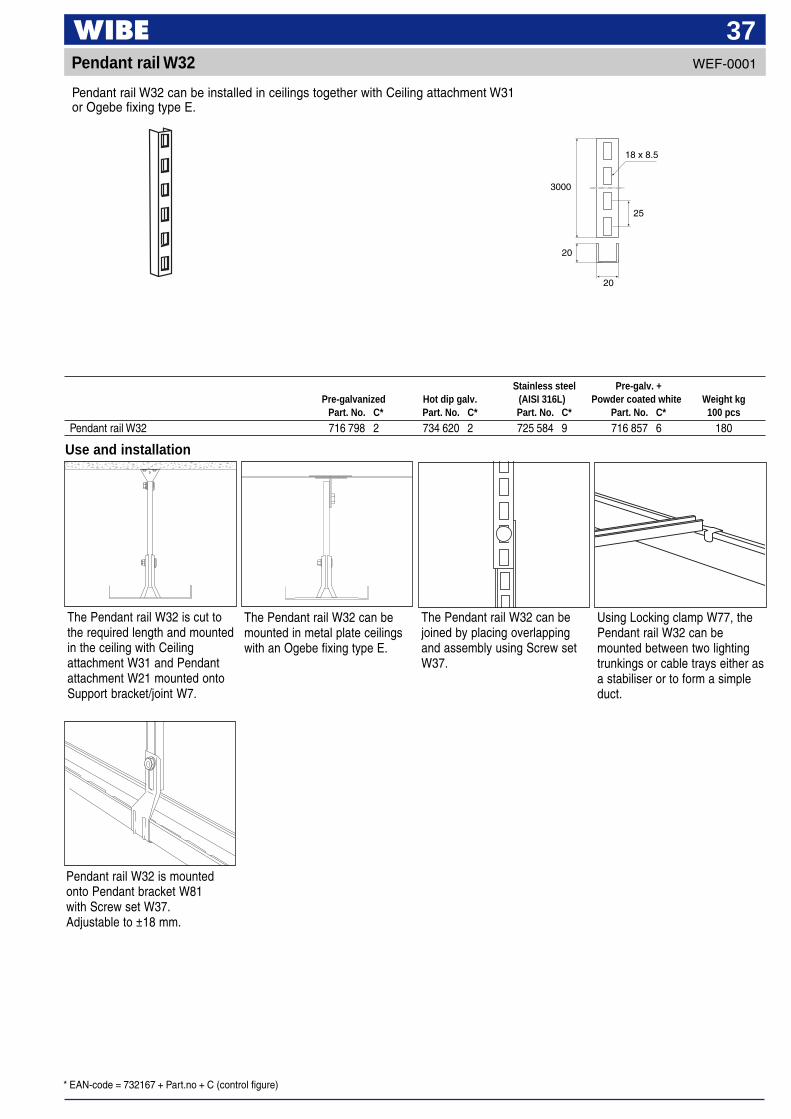
37Pendant rail W32
3000
18 x 8.5
25
20
20
Use and installation
The Pendant rail W32 is cut tothe required length and mountedin the ceiling with Ceilingattachment W31 and Pendantattachment W21 mounted ontoSupport bracket/joint W7.
The Pendant rail W32 can bemounted in metal plate ceilingswith an Ogebe fixing type E.
The Pendant rail W32 can bejoined by placing overlappingand assembly using Screw setW37.
Using Locking clamp W77, thePendant rail W32 can bemounted between two lightingtrunkings or cable trays either asa stabiliser or to form a simpleduct.
Pendant rail W32 can be installed in ceilings together with Ceiling attachment W31or Ogebe fixing type E.
Stainless steel Pre-galv. +Pre-galvanized Hot dip galv. (AISI 316L) Powder coated white Weight kg
Part. No. C* Part. No. C* Part. No. C* Part. No. C* 100 pcs
Pendant rail W32 716 798 2 734 620 2 725 584 9 716 857 6 180
Pendant rail W32 is mountedonto Pendant bracket W81with Screw set W37.Adjustable to ±18 mm.
WEF-0001

* EAN-code = 732167 + Part.no + C (control figure)
38Pendant strip W33
Pre-galv +L Pre-galvanized Powder coated white Weight kg
mm Part. No. C* Part. No. C* 100 pcs
Pendant strip W33 1000 721 786 1 723 910 8 19
Use and installation
If an adjustment of pendantlength is required, this can beachieved by cutting the strip inthe middle and overlapping thetwo parts so that a join can beachieved using Screw set W36.
Mounted in open intersectionsfor ceiling installation. Mountedwith Screw set W36 in Supportbracket/joint W7.
The Pendant strip W33 isdelivered straight. Can be benton site. Pendants longer than1 m are joined by overlappingusing Screw set W36.
L
50
25
8.5 x 35
The Pendant strip W33 is delivered in straight 1 m lengths and bent on site.
WEF-0001
* EAN-code = 732167 + Part.no + C (control figure)
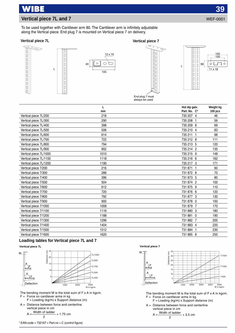
39WEF-0001Vertical piece 7L and 7
To be used together with Cantilever arm 80. The Cantilever arm is infinitely adjustablealong the Vertical piece. End plug 7 is mounted on Vertical piece 7 on delivery.
L Hot dip galv. Weight kgmm Part. No. C* 100 pcs
Vertical piece 7L/200 218 735 207 4 46Vertical piece 7L/300 290 735 208 1 56Vertical piece 7L/400 398 735 209 8 69Vertical piece 7L/500 506 735 210 4 83Vertical piece 7L/600 614 735 211 1 98Vertical piece 7L/700 722 735 212 8 111Vertical piece 7L/800 794 735 213 5 120Vertical piece 7L/900 902 735 214 2 135Vertical piece 7L/1000 1010 735 215 9 148Vertical piece 7L/1100 1118 735 216 6 162Vertical piece 7L/1200 1190 735 217 3 171Vertical piece 7/200 216 731 871 1 60Vertical piece 7/300 288 731 872 8 70Vertical piece 7/400 396 731 873 5 80Vertical piece 7/500 504 731 874 2 100Vertical piece 7/600 612 731 875 9 110Vertical piece 7/700 720 731 876 6 120Vertical piece 7/800 792 731 877 3 130Vertical piece 7/900 900 731 878 0 150Vertical piece 7/1000 1008 731 879 7 170Vertical piece 7/1100 1116 731 880 3 180Vertical piece 7/1200 1188 731 881 0 190Vertical piece 7/1300 1296 731 882 7 200Vertical piece 7/1400 1404 731 883 4 220Vertical piece 7/1500 1512 731 884 1 230Vertical piece 7/1600 1620 731 885 8 250
Loading tables for Vertical piece 7L and 7
Vertical piece 7L
L
40
12 x 19
105
L58
11 x 18
150120
End plug 7 mustalways be used
Vertical piece 7
The bending moment M is the total sum of F x A in kgcm.F = Force on cantilever arms in kg
F = Loading (kg/m) x Support distance (m)
A = Distance between force and centerlinevertical piece in cm
A = + 1.75 cmWidth of ladder
2
Def
lect
ion
mm
M in kgcm
10
15
20
25
30
35
5
7/1500
7/1000
7/500
1000 2000 3000 4000 5000
Vertical piece 7
Def
lect
ion
mm
10
15
20
25
5
1000 2000 3000M in kgcm
7L/700
7L/500
7L/200
7L/900
7L/1200
Vertical piece 7L
M
Deflection
A
AF
F
The bending moment M is the total sum of F x A in kgcm.F = Force on cantilever arms in kg
F = Loading (kg/m) x Support distance (m)
A = Distance between force and centerlinevertical piece in cm
A = + 3.5 cmWidth of ladder
2
M
Deflection
A
AF
F
40Vertical piece 7L and 7
Use and installation
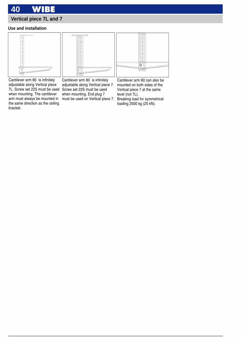
Cantilever arm 80 is infinitelyadjustable along Vertical piece 7.Screw set 22S must be usedwhen mounting. End plug 7must be used on Vertical piece 7.
Cantilever arm 80 is infinitelyadjustable along Vertical piece7L. Screw set 22S must be usedwhen mounting. The cantileverarm must always be mounted inthe same direction as the ceilingbracket.
Cantilever arm 80 can also bemounted on both sides of theVertical piece 7 at the samelevel (not 7L).Breaking load for symmetricalloading 2500 kg (25 kN).
* EAN-code = 732167 + Part.no + C (control figure)
41WEF-0001
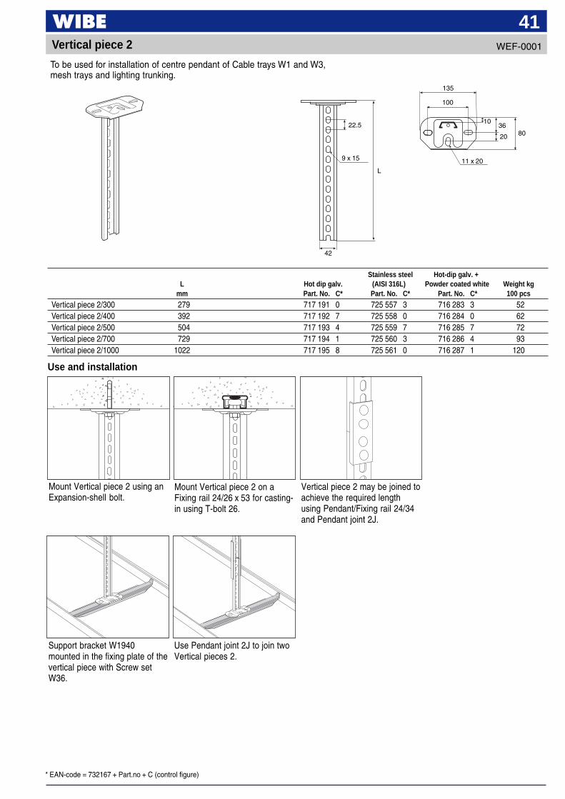
To be used for installation of centre pendant of Cable trays W1 and W3,mesh trays and lighting trunking.
Vertical piece 2
Use and installation
Stainless steel Hot-dip galv. +L Hot dip galv. (AISI 316L) Powder coated white Weight kg
mm Part. No. C* Part. No. C* Part. No. C* 100 pcs
Vertical piece 2/300 279 717 191 0 725 557 3 716 283 3 52Vertical piece 2/400 392 717 192 7 725 558 0 716 284 0 62Vertical piece 2/500 504 717 193 4 725 559 7 716 285 7 72Vertical piece 2/700 729 717 194 1 725 560 3 716 286 4 93Vertical piece 2/1000 1022 717 195 8 725 561 0 716 287 1 120
Mount Vertical piece 2 using anExpansion-shell bolt.
Mount Vertical piece 2 on aFixing rail 24/26 x 53 for casting-in using T-bolt 26.
Vertical piece 2 may be joined toachieve the required lengthusing Pendant/Fixing rail 24/34and Pendant joint 2J.
22.5
9 x 15
L
42
Support bracket W1940mounted in the fixing plate of thevertical piece with Screw setW36.
Use Pendant joint 2J to join twoVertical pieces 2.
135
3610
100
80
11 x 20
20
* EAN-code = 732167 + Part.no + C (control figure)
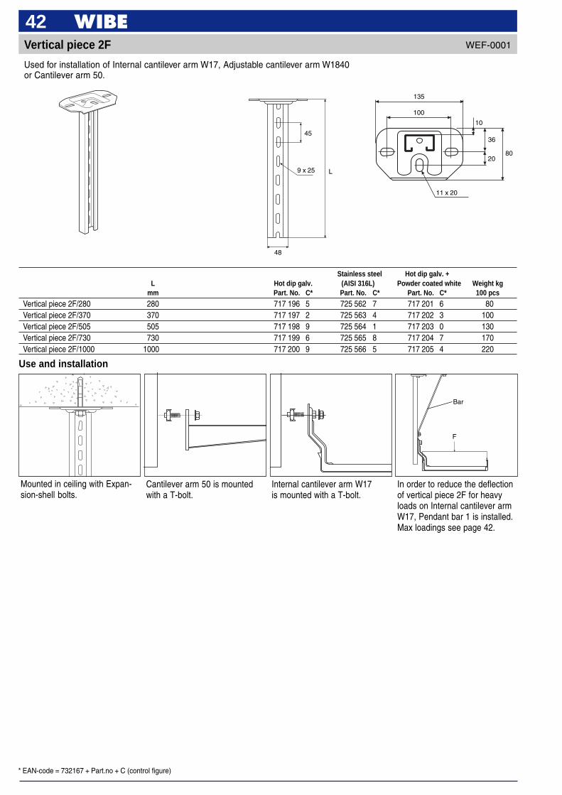
42WEF-0001Vertical piece 2F
45
135
36
100
10
80
11 x 20
20
9 x 25
48
L
Use and installation
Mounted in ceiling with Expan-sion-shell bolts.
Cantilever arm 50 is mountedwith a T-bolt.
Internal cantilever arm W17is mounted with a T-bolt.
In order to reduce the deflectionof vertical piece 2F for heavyloads on Internal cantilever armW17, Pendant bar 1 is installed.Max loadings see page 42.
Stainless steel Hot dip galv. +L Hot dip galv. (AISI 316L) Powder coated white Weight kg
mm Part. No. C* Part. No. C* Part. No. C* 100 pcs
Vertical piece 2F/280 280 717 196 5 725 562 7 717 201 6 80Vertical piece 2F/370 370 717 197 2 725 563 4 717 202 3 100Vertical piece 2F/505 505 717 198 9 725 564 1 717 203 0 130Vertical piece 2F/730 730 717 199 6 725 565 8 717 204 7 170Vertical piece 2F/1000 1000 717 200 9 725 566 5 717 205 4 220
Used for installation of Internal cantilever arm W17, Adjustable cantilever arm W1840or Cantilever arm 50.
F
Bar
* EAN-code = 732167 + Part.no + C (control figure)
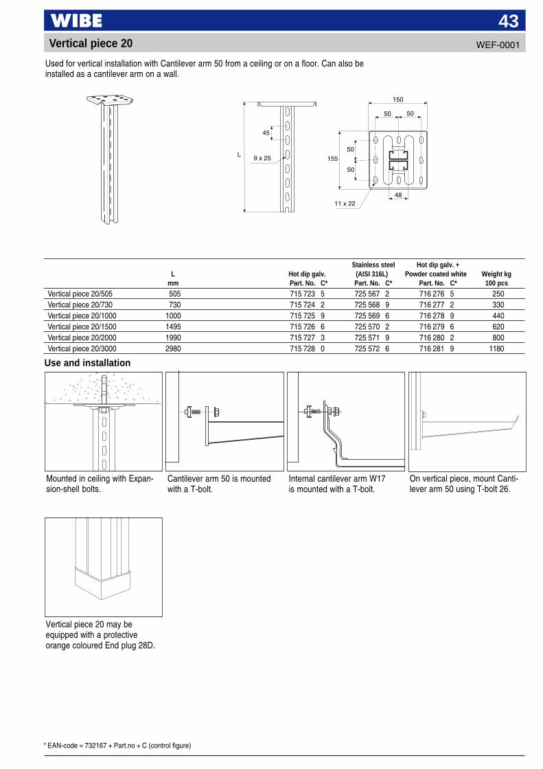
43Vertical piece 20
Used for vertical installation with Cantilever arm 50 from a ceiling or on a floor. Can also beinstalled as a cantilever arm on a wall.
Stainless steel Hot dip galv. +L Hot dip galv. (AISI 316L) Powder coated white Weight kg
mm Part. No. C* Part. No. C* Part. No. C* 100 pcs
Vertical piece 20/505 505 715 723 5 725 567 2 716 276 5 250Vertical piece 20/730 730 715 724 2 725 568 9 716 277 2 330Vertical piece 20/1000 1000 715 725 9 725 569 6 716 278 9 440Vertical piece 20/1500 1495 715 726 6 725 570 2 716 279 6 620Vertical piece 20/2000 1990 715 727 3 725 571 9 716 280 2 800Vertical piece 20/3000 2980 715 728 0 725 572 6 716 281 9 1180
L
150
45
50 50
1559 x 2550
50
11 x 2248
WEF-0001
Use and installation
Mounted in ceiling with Expan-sion-shell bolts.
Cantilever arm 50 is mountedwith a T-bolt.
Internal cantilever arm W17is mounted with a T-bolt.
On vertical piece, mount Canti-lever arm 50 using T-bolt 26.
Vertical piece 20 may beequipped with a protectiveorange coloured End plug 28D.

* EAN-code = 732167 + Part.no + C (control figure)
44Pendant bar 1
Pendant bar 1/300–800
Hot dip galv. +A B Hot dip galv. Powder coated white Weight kg
mm mm Part. No. C* Part. No. C* 100 pcs
Pendant bar 1/300 80 300 717 640 3 717 643 4 50Pendant bar 1/500 130 500 717 641 0 717 644 1 80Pendant bar 1/800 215 800 717 642 7 717 645 8 125Pendant bar 1/1500 May vary 718 903 8 720 530 1 560
Installed in order to reduce the deflection of long Vertical pieces 2F and 20.
A
B
Ø11
Pendant bar 1/1500
B
A
WEF-0001
Use and installation
In order to reduce deflection ofVertical piece 2F for heavy loadson Internal cantilever arm W17and Cantilever arm 50/50L,Pendant bar 1 is installed.Loadings in accordance withtable below.
F kp
Bend on site to requiredangle
Pendant bar 1
T-bolt
Cantilever arm 2F/280 2F/370 2F/505 2F/730 2F/1000
type kN kg kN kg kN kg kN kg kN kg
Without bar W17/100 0.65 65 0.65 65 0.60 60 0.55 55 0.55 55200 0.60 60 0.60 60 0.50 50 0.50 50 0.45 45300 0.70 70 0.70 70 0.70 70 0.65 65 0.55 55400 0.55 55 0.55 55 0.55 55 0.50 50 0.45 45
With bar 1/300 W17/100 0.75 75 0.70 70 0.65 65200 0.60 60 0.55 55 0.50 50300 0.80 80 0.75 75 0.70 70400 0.70 70 0.65 65 0.50 50
With bar 1/500 W17/100 0.90 90 0.70 70200 0.70 70 0.60 60300 0.95 95 0.80 80400 0.70 70 0.55 55
With bar 1/800 W17/100 0.80 80200 0.60 60300 0.85 85400 0.65 65
Loading table for Cantilever arm W17Max. loading F at 3° deflection of cantilever arm
* EAN-code = 732167 + Part.no + C (control figure)
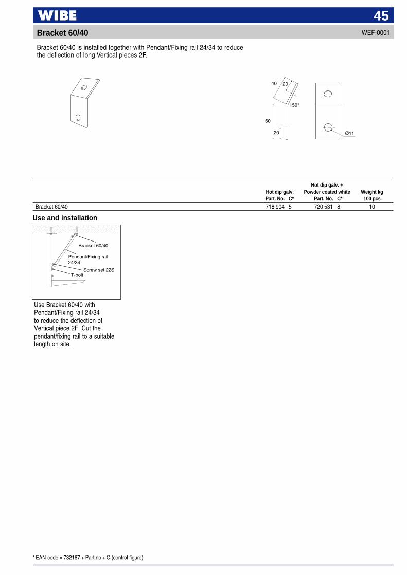
45WEF-0001Bracket 60/40
Bracket 60/40 is installed together with Pendant/Fixing rail 24/34 to reducethe deflection of long Vertical pieces 2F.
20
60
Ø11
150°
40 20
Use and installation
Bracket 60/40
Pendant/Fixing rail24/34
Screw set 22ST-bolt
Use Bracket 60/40 withPendant/Fixing rail 24/34to reduce the deflection ofVertical piece 2F. Cut thependant/fixing rail to a suitablelength on site.
Hot dip galv. +Hot dip galv. Powder coated white Weight kgPart. No. C* Part. No. C* 100 pcs
Bracket 60/40 718 904 5 720 531 8 10
* EAN-code = 732167 + Part.no + C (control figure)
46
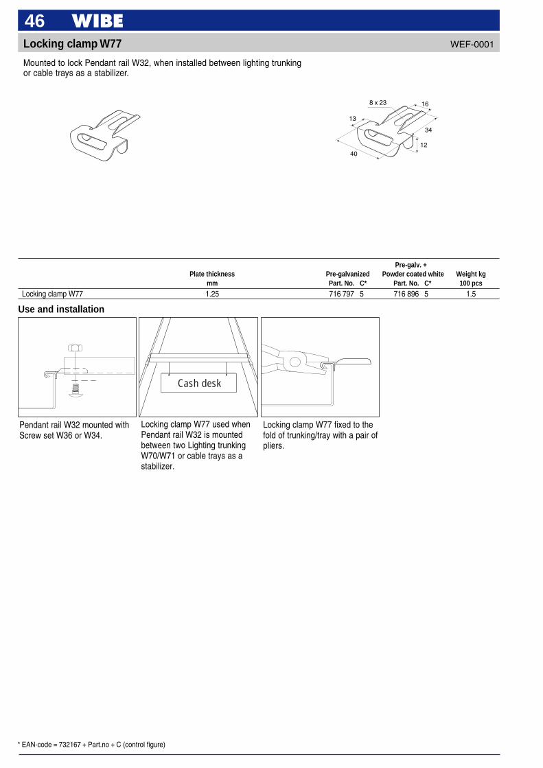
8 x 23 16
34
1240
13
Locking clamp W77
Mounted to lock Pendant rail W32, when installed between lighting trunkingor cable trays as a stabilizer.
WEF-0001
Use and installation
Pendant rail W32 mounted withScrew set W36 or W34.
Locking clamp W77 used whenPendant rail W32 is mountedbetween two Lighting trunkingW70/W71 or cable trays as astabilizer.
Pre-galv. +Plate thickness Pre-galvanized Powder coated white Weight kg
mm Part. No. C* Part. No. C* 100 pcs
Locking clamp W77 1.25 716 797 5 716 896 5 1.5
Cash desk
Locking clamp W77 fixed to thefold of trunking/tray with a pair ofpliers.
* EAN-code = 732167 + Part.no + C (control figure)
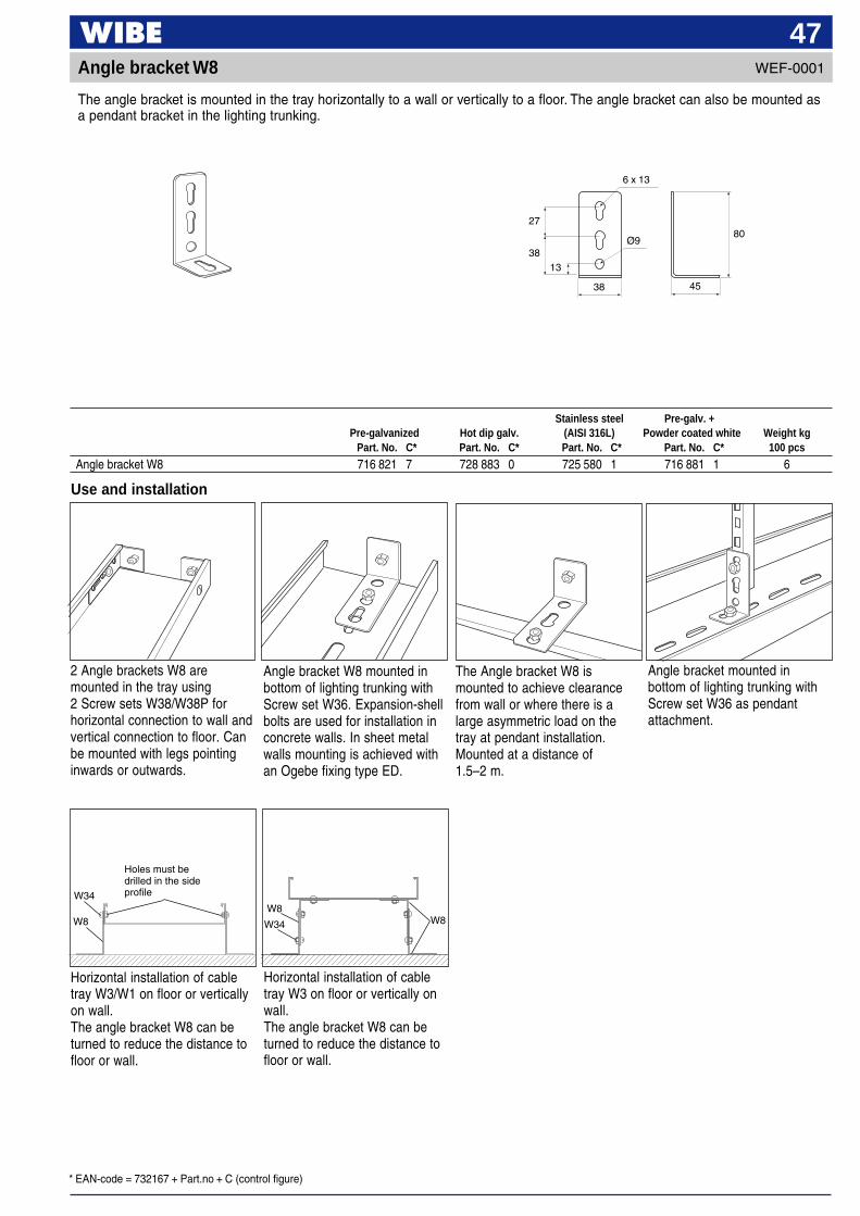
47WEF-0001Angle bracket W8
The angle bracket is mounted in the tray horizontally to a wall or vertically to a floor. The angle bracket can also be mounted asa pendant bracket in the lighting trunking.
6 x 13
27
3813
Ø9
4538
80
Use and installation
2 Angle brackets W8 aremounted in the tray using2 Screw sets W38/W38P forhorizontal connection to wall andvertical connection to floor. Canbe mounted with legs pointinginwards or outwards.
Angle bracket W8 mounted inbottom of lighting trunking withScrew set W36. Expansion-shellbolts are used for installation inconcrete walls. In sheet metalwalls mounting is achieved withan Ogebe fixing type ED.
The Angle bracket W8 ismounted to achieve clearancefrom wall or where there is alarge asymmetric load on thetray at pendant installation.Mounted at a distance of1.5–2 m.
Angle bracket mounted inbottom of lighting trunking withScrew set W36 as pendantattachment.
Stainless steel Pre-galv. +Pre-galvanized Hot dip galv. (AISI 316L) Powder coated white Weight kg
Part. No. C* Part. No. C* Part. No. C* Part. No. C* 100 pcs
Angle bracket W8 716 821 7 728 883 0 725 580 1 716 881 1 6
Horizontal installation of cabletray W3/W1 on floor or verticallyon wall.The angle bracket W8 can beturned to reduce the distance tofloor or wall.
Horizontal installation of cabletray W3 on floor or vertically onwall.The angle bracket W8 can beturned to reduce the distance tofloor or wall.
Holes must bedrilled in the sideprofile
W8
W34W8
W34 W8
* EAN-code = 732167 + Part.no + C (control figure)
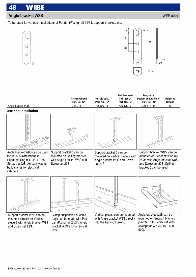
48Angle bracket W8S
30 30
30
39
18
120
10 x 22
Stainless steel Pre-galv. +Pre-galvanized Hot dip galv. (AISI 316L) Powder coated white Weight kgPart. No. C* Part. No. C* Part. No. C* Part. No. C* 100 pcs
Angle bracket W8S 728 071 1 726 873 3 726 875 7 726 874 0 8
Use and installation
Angle bracket W8S can be usedfor various installations inPendant/fixing rail 24/34. UseScrew set 22S. An easy way tobuild stands for electricalcabinets.
Support bracket WN5 can bemounted on Pendant/fixing rail24/34 with Angle bracket W8Sand Screw set 22S. Ceilingbracket 5 can be used.
Support bracket 6 can bemounted on Ceiling bracket 5with Angle bracket W8S andScrew set 22S.
Support bracket 6 can bemounted on Vertical piece 2 withAngle bracket W8S and Screwset 22S.
Support bracket WN5 can bemounted directly on Verticalpiece 2 with Angle bracket W8Sand Screw set 22S.
Clamp suspension of cabletrays can be made with Pen-dant/Fixing rail 24/34, Anglebracket W8S and Screw set22S.
Vertical pieces can be mountedwith Angle bracket W8S directlyinto the lighting trunking.
WEF-0001
To be used for various installations of Pendant/Fixing rail 24/34, support brackets etc.
10
Angle bracket W8S can bemounted on Support bracket/joint W7 with Screw set W36(except for W7-70, 150, 500,600).

* EAN-code = 732167 + Part.no + C (control figure)
49WEF-0001T-joint W9
6 x 10
50
72.5
Mounted in T- or X-branches. Also used for oblique branches.
Pre-galv. +Plate thickness Pre-galvanized Hot dip galv. Powder coated white Weight kg
mm Part. No. C* Part. No. C* Part. No. C* 100 pcs
T-joint W9 (Screw M5 x 10 + Nut M6M5 are incl.)** 1.0 718 205 3 734 622 6 718 206 0 6
** 2 T-joints W9 + 2 screw sets are included in each Part. No.
Use and installation
Potential balancingIn order to fulfil the potentialbalancing according to SS-EN60335-1 the screw must besecured.1 Self-drilling screw
RXB 4.2 x 132 Screw set W38P
Tightening torque 2 Nm
Oblique angling. If necessary,the lugs are locked to the edgeof the tray using pliers. Can alsobe locked with blind rivets orself-tapping screws.
Straight angling. If necessary,the lugs are locked to the edgeof the tray using pliers. Canalso be locked with blind rivetsor self-tapping screws.
T-joint W9 is mounted on theside edges of the tray.
1
2
* EAN-code = 732167 + Part.no + C (control figure)
50T-joint W29
B
A
67
Pre-galv. +A B Pre-galvanized Powder coated white Weight kg
mm mm Part. No. C* Part. No. C* 100 pcs
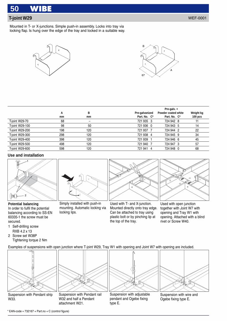
T-joint W29-70 68 – 721 935 3 724 942 8 11T-joint W29-100 98 50 721 936 0 724 943 5 14T-joint W29-200 198 120 721 937 7 724 944 2 22T-joint W29-300 298 120 721 938 4 724 945 9 34T-joint W29-400 398 120 721 939 1 724 946 6 45T-joint W29-500 498 120 721 940 7 724 947 3 57T-joint W29-600 598 120 721 941 4 724 948 0 68
Use and installation
Simply installed with push-inmounting. Automatic locking vialocking lips.
Used with T- and X-junction.Mounted directly onto tray edge.Can be attached to tray usingplastic bolt or by pinching lip atthe top of the tray.
Used with open junctiontogether with Joint W7 withopening and Tray W1 withopening. Attached with a blindrivet or Screw W40.
Examples of suspensions with open junction where T-joint W29, Tray W1 with opening and Joint W7 with opening are included.
Suspension with wire andOgebe fixing type E.
Suspension with adjustablependant and Ogebe fixingtype E.
Suspension with Pendant railW32 and half a Pendantattachment W21.
Suspension with Pendant stripW33.
Mounted in T- or X-junctions. Simple push-in assembly. Locks into tray vialocking flap. Is hung over the edge of the tray and locked in a suitable way.
WEF-0001
Potential balancingIn order to fulfil the potentialbalancing according to SS-EN60335-1 the screw must besecured.1 Self-drilling screw
RXB 4.2 x 132 Screw set W38P
Tightening torque 2 Nm
2
1
* EAN-code = 732167 + Part.no + C (control figure)
51WEF-0001Adjustable bend W10S
Use and installation
Ø6
A 3333
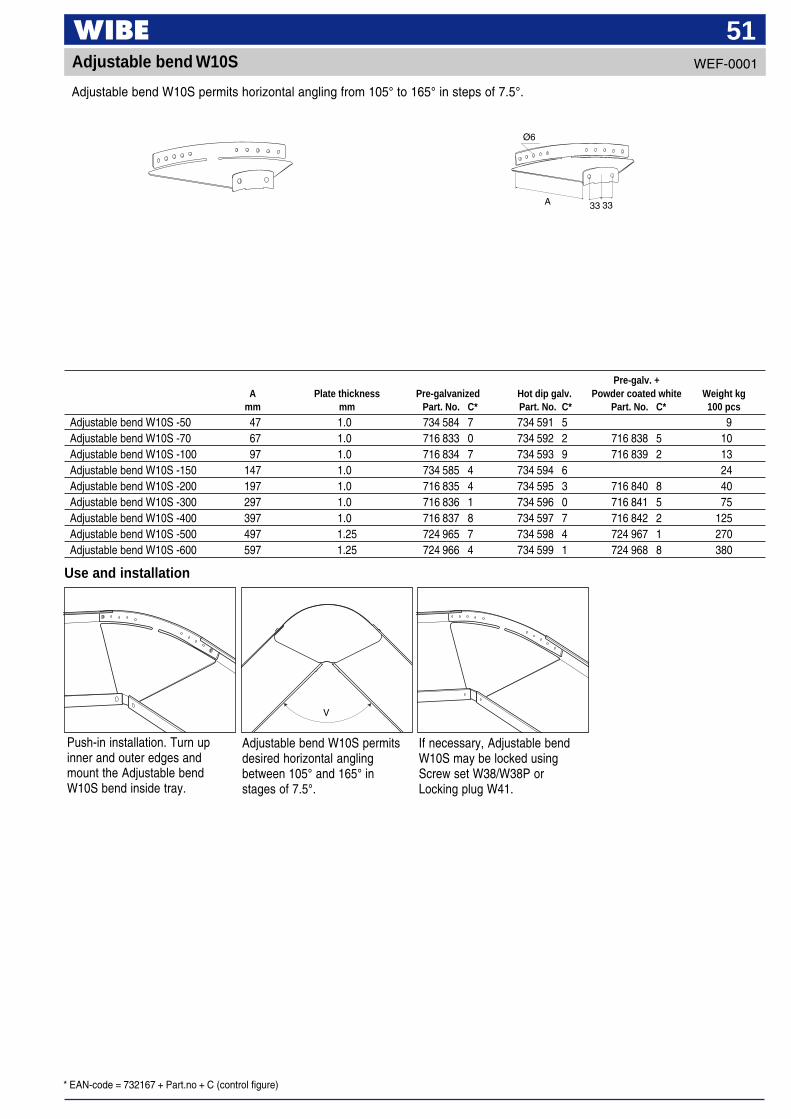
If necessary, Adjustable bendW10S may be locked usingScrew set W38/W38P orLocking plug W41.
Adjustable bend W10S permitsdesired horizontal anglingbetween 105° and 165° instages of 7.5°.
V
Push-in installation. Turn upinner and outer edges andmount the Adjustable bendW10S bend inside tray.
Pre-galv. +A Plate thickness Pre-galvanized Hot dip galv. Powder coated white Weight kg
mm mm Part. No. C* Part. No. C* Part. No. C* 100 pcs
Adjustable bend W10S -50 47 1.0 734 584 7 734 591 5 9Adjustable bend W10S -70 67 1.0 716 833 0 734 592 2 716 838 5 10Adjustable bend W10S -100 97 1.0 716 834 7 734 593 9 716 839 2 13Adjustable bend W10S -150 147 1.0 734 585 4 734 594 6 24Adjustable bend W10S -200 197 1.0 716 835 4 734 595 3 716 840 8 40Adjustable bend W10S -300 297 1.0 716 836 1 734 596 0 716 841 5 75Adjustable bend W10S -400 397 1.0 716 837 8 734 597 7 716 842 2 125Adjustable bend W10S -500 497 1.25 724 965 7 734 598 4 724 967 1 270Adjustable bend W10S -600 597 1.25 724 966 4 734 599 1 724 968 8 380
Adjustable bend W10S permits horizontal angling from 105° to 165° in steps of 7.5°.
* EAN-code = 732167 + Part.no + C (control figure)
5290° bend W10 SKH
Use and installation
5.8 x 9
100
A
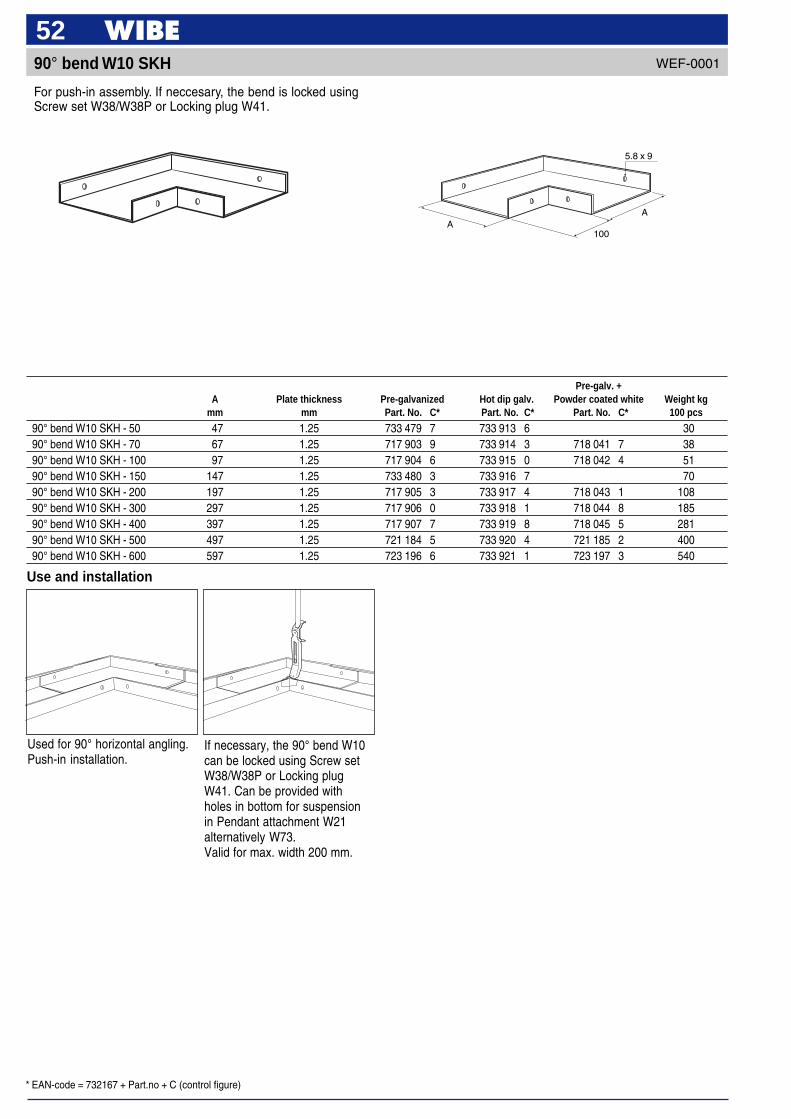
If necessary, the 90° bend W10can be locked using Screw setW38/W38P or Locking plugW41. Can be provided withholes in bottom for suspensionin Pendant attachment W21alternatively W73.Valid for max. width 200 mm.
Used for 90° horizontal angling.Push-in installation.
Pre-galv. +A Plate thickness Pre-galvanized Hot dip galv. Powder coated white Weight kg
mm mm Part. No. C* Part. No. C* Part. No. C* 100 pcs
90° bend W10 SKH - 50 47 1.25 733 479 7 733 913 6 3090° bend W10 SKH - 70 67 1.25 717 903 9 733 914 3 718 041 7 3890° bend W10 SKH - 100 97 1.25 717 904 6 733 915 0 718 042 4 5190° bend W10 SKH - 150 147 1.25 733 480 3 733 916 7 7090° bend W10 SKH - 200 197 1.25 717 905 3 733 917 4 718 043 1 10890° bend W10 SKH - 300 297 1.25 717 906 0 733 918 1 718 044 8 18590° bend W10 SKH - 400 397 1.25 717 907 7 733 919 8 718 045 5 28190° bend W10 SKH - 500 497 1.25 721 184 5 733 920 4 721 185 2 40090° bend W10 SKH - 600 597 1.25 723 196 6 733 921 1 723 197 3 540
WEF-0001
For push-in assembly. If neccesary, the bend is locked usingScrew set W38/W38P or Locking plug W41.
A
* EAN-code = 732167 + Part.no + C (control figure)
53WEF-0001T-junction W12 SKH
A
A
A
100
5.8 x 9
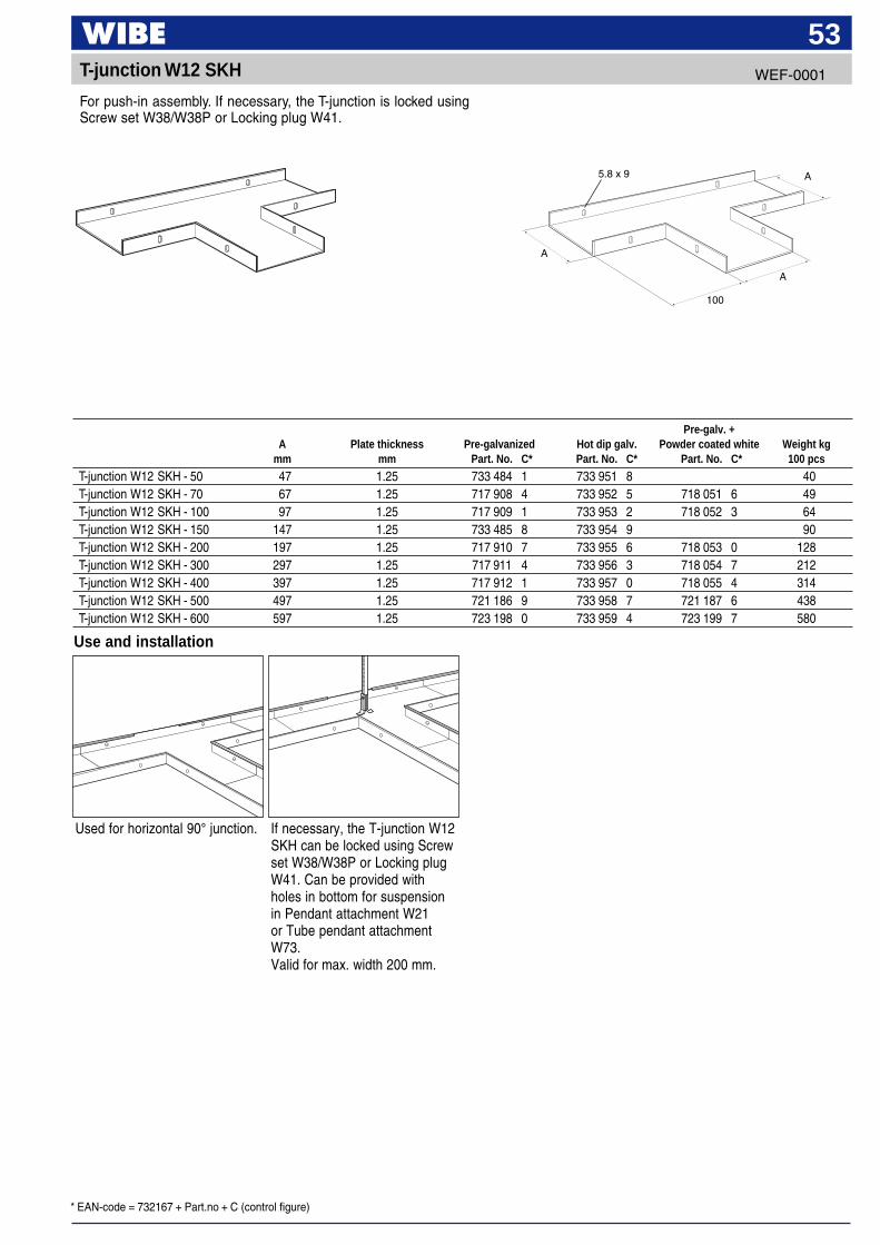
For push-in assembly. If necessary, the T-junction is locked usingScrew set W38/W38P or Locking plug W41.
Pre-galv. +A Plate thickness Pre-galvanized Hot dip galv. Powder coated white Weight kg
mm mm Part. No. C* Part. No. C* Part. No. C* 100 pcs
T-junction W12 SKH - 50 47 1.25 733 484 1 733 951 8 40T-junction W12 SKH - 70 67 1.25 717 908 4 733 952 5 718 051 6 49T-junction W12 SKH - 100 97 1.25 717 909 1 733 953 2 718 052 3 64T-junction W12 SKH - 150 147 1.25 733 485 8 733 954 9 90T-junction W12 SKH - 200 197 1.25 717 910 7 733 955 6 718 053 0 128T-junction W12 SKH - 300 297 1.25 717 911 4 733 956 3 718 054 7 212T-junction W12 SKH - 400 397 1.25 717 912 1 733 957 0 718 055 4 314T-junction W12 SKH - 500 497 1.25 721 186 9 733 958 7 721 187 6 438T-junction W12 SKH - 600 597 1.25 723 198 0 733 959 4 723 199 7 580
Use and installation
Used for horizontal 90° junction. If necessary, the T-junction W12SKH can be locked using Screwset W38/W38P or Locking plugW41. Can be provided withholes in bottom for suspensionin Pendant attachment W21or Tube pendant attachmentW73.Valid for max. width 200 mm.

* EAN-code = 732167 + Part.no + C (control figure)
54X-junction W13 SKH
A
A
100
A
A
5.8 x 9
A
A
Pre-galv. +A Plate thickness Pre-galvanized Hot dip galv. Powder coated white Weight kg
mm mm Part. No. C* Part. No. C* Part. No. C* 100 pcs
X-junction W13 SKH - 50 47 1.25 733 496 4 733 960 0 50X-junction W13 SKH - 70 67 1.25 717 913 8 733 961 7 718 061 5 64X-junction W13 SKH - 100 97 1.25 717 914 5 733 962 4 718 062 2 80X-junction W13 SKH - 150 147 1.25 733 497 1 733 963 1 110X-junction W13 SKH - 200 197 1.25 717 915 2 733 964 8 718 063 9 150X-junction W13 SKH - 300 297 1.25 717 916 9 733 965 5 718 064 6 240X-junction W13 SKH - 400 397 1.25 717 917 6 733 966 2 718 065 3 350X-junction W13 SKH - 500 497 1.25 721 188 3 733 967 9 721 189 0 480X-junction W13 SKH - 600 597 1.25 723 200 0 733 968 6 723 201 7 630
Mounted with Screw set W36under 90° bend W10 SKH if oneneeds to level out differences inheight between tray and bend.
Pre-galv. +A Plate thickness Pre-galvanized Powder coated white Weight kg
mm mm Part. No. C* Part. No. C* 100 pcs
Cover plate W16 - 70 70 1.5 718 036 3 718 071 4 6Cover plate W16 - 100 100 1.5 718 037 0 718 072 1 12Cover plate W16 - 200 200 1.5 718 038 7 718 073 8 48Cover plate W16 - 300 300 1.5 718 039 4 718 074 5 108Cover plate W16 - 400 400 1.5 718 040 0 718 075 2 192
Use and installation
Cover plate W16
For push-in assembly. If necessary, the X-junction is lockedusing Screw set W38/W38P or Locking plug W41.
Mounted with Screw set W36 under 90° bends, T- and X-junction if oneneeds to level out differences in levels between tray and junction.
Use and installation
If necessary, the X-junctionW13 SKH can be locked usingScrew set W38/W38P orLocking plug W41. Can beprovided with holes in bottom forsuspension in Pendant attach-ment W21 or Tube pendantattachment W73.Valid for max. width 200.
Used for horizontal 90°junction.
WEF-0001
WEF-0001
* EAN-code = 732167 + Part.no + C (control figure)
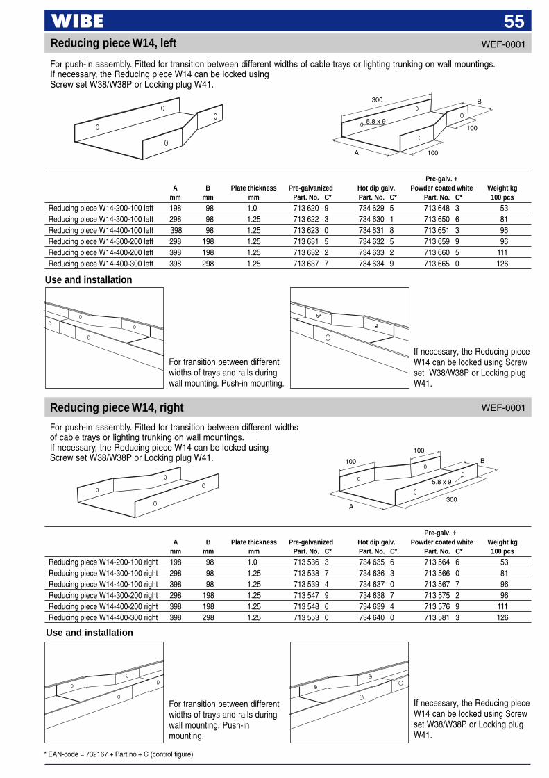
55Reducing piece W14, left
For push-in assembly. Fitted for transition between different widths of cable trays or lighting trunking on wall mountings.If necessary, the Reducing piece W14 can be locked usingScrew set W38/W38P or Locking plug W41.
Pre-galv. +A B Plate thickness Pre-galvanized Hot dip galv. Powder coated white Weight kg
mm mm mm Part. No. C* Part. No. C* Part. No. C* 100 pcs
Reducing piece W14-200-100 left 198 98 1.0 713 620 9 734 629 5 713 648 3 53Reducing piece W14-300-100 left 298 98 1.25 713 622 3 734 630 1 713 650 6 81Reducing piece W14-400-100 left 398 98 1.25 713 623 0 734 631 8 713 651 3 96Reducing piece W14-300-200 left 298 198 1.25 713 631 5 734 632 5 713 659 9 96Reducing piece W14-400-200 left 398 198 1.25 713 632 2 734 633 2 713 660 5 111Reducing piece W14-400-300 left 398 298 1.25 713 637 7 734 634 9 713 665 0 126
Use and installation
For transition between differentwidths of trays and rails duringwall mounting. Push-in mounting.
If necessary, the Reducing pieceW14 can be locked using Screwset W38/W38P or Locking plugW41.
Use and installation
For transition between differentwidths of trays and rails duringwall mounting. Push-inmounting.
If necessary, the Reducing pieceW14 can be locked using Screwset W38/W38P or Locking plugW41.
Reducing piece W14, right
Pre-galv. +A B Plate thickness Pre-galvanized Hot dip galv. Powder coated white Weight kg
mm mm mm Part. No. C* Part. No. C* Part. No. C* 100 pcs
Reducing piece W14-200-100 right 198 98 1.0 713 536 3 734 635 6 713 564 6 53Reducing piece W14-300-100 right 298 98 1.25 713 538 7 734 636 3 713 566 0 81Reducing piece W14-400-100 right 398 98 1.25 713 539 4 734 637 0 713 567 7 96Reducing piece W14-300-200 right 298 198 1.25 713 547 9 734 638 7 713 575 2 96Reducing piece W14-400-200 right 398 198 1.25 713 548 6 734 639 4 713 576 9 111Reducing piece W14-400-300 right 398 298 1.25 713 553 0 734 640 0 713 581 3 126
For push-in assembly. Fitted for transition between different widthsof cable trays or lighting trunking on wall mountings.If necessary, the Reducing piece W14 can be locked usingScrew set W38/W38P or Locking plug W41.
WEF-0001
WEF-0001
5.8 x 9
A
B
100
100
300
A
5.8 x 9
B100
100
300

* EAN-code = 732167 + Part.no + C (control figure)
56WEF-0001
For push-in assembly. Fitted for transition between different cable tray widthsfor symmetric ceiling installation. If necessary, the Reducing piece W15 can belocked using Screw set W38/W38P or Locking plug W41.
Reducing piece W15, straight
Use and installation
If necessary, the Reducingpiece W15 can be locked usingScrew set W38/W38P orLocking plug W41.
For transition between differenttray widths during symmetricceiling installation
End cover W45
Use and installation
Mounted as end in trays andlighting trunking. Locked withLocking plug W41 or Screw setW38/W38P.
100
A
Ø6 x 55
Pre-galv. +A B Plate thickness Pre-galvanized Hot dip galv. Powder coated white Weight kg
mm mm mm Part. No. C* Part. No. C* Part. No. C* 100 pcs
Reducing piece W15 200-100, straight 198 98 1.0 713 704 6 734 623 3 713 732 9 53Reducing piece W15 300-100, straight 298 98 1.25 713 706 0 734 624 0 713 734 3 81Reducing piece W15 400-100, straight 398 98 1.25 713 707 7 734 625 7 713 735 0 96Reducing piece W15 300-200, straight 298 198 1.25 713 715 2 734 626 4 713 743 5 96Reducing piece W15 400-200, straight 398 198 1.25 713 716 9 734 627 1 713 744 2 111Reducing piece W15 400-300, straight 398 298 1.25 713 721 3 734 628 8 713 749 7 126
Pre-galv. +A Pre-galvanized Powder coated white Weight kg
mm Part. No. C* Part. No. C* 100 pcs
End cover W45-70 68 731 730 1 731 737 0 8End cover W45-100 98 731 731 8 731 738 7 9End cover W45-200 198 731 732 5 731 739 4 12End cover W45-300 298 731 733 2 731 740 0 15End cover W45-400 398 731 734 9 731 741 7 18End cover W45-500 498 731 735 5 731 742 4 21End cover W45-600 598 731 736 1 731 743 1 24
A300
B
100
100
5.8 x 9
For push-in assembly. Mounted as end cover in cable trays and lighting trunking. If required,the End cover W45 can be locked using Screw set W38/W38P or Locking plug W41.
WEF-0001
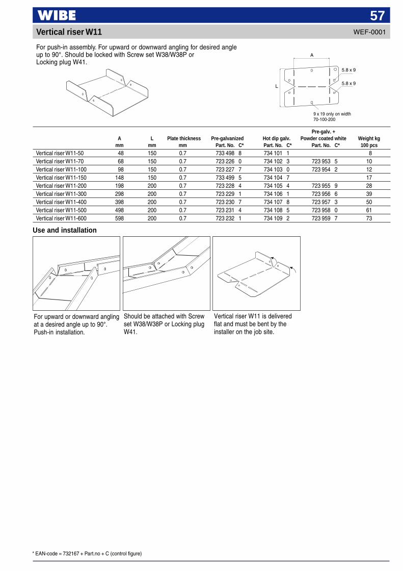
* EAN-code = 732167 + Part.no + C (control figure)
57Vertical riser W11
For push-in assembly. For upward or downward angling for desired angleup to 90°. Should be locked with Screw set W38/W38P orLocking plug W41.
Should be attached with Screwset W38/W38P or Locking plugW41.
For upward or downward anglingat a desired angle up to 90°.Push-in installation.
Use and installation
Pre-galv. +A L Plate thickness Pre-galvanized Hot dip galv. Powder coated white Weight kg
mm mm mm Part. No. C* Part. No. C* Part. No. C* 100 pcs
Vertical riser W11-50 48 150 0.7 733 498 8 734 101 1 8Vertical riser W11-70 68 150 0.7 723 226 0 734 102 3 723 953 5 10Vertical riser W11-100 98 150 0.7 723 227 7 734 103 0 723 954 2 12Vertical riser W11-150 148 150 0.7 733 499 5 734 104 7 17Vertical riser W11-200 198 200 0.7 723 228 4 734 105 4 723 955 9 28Vertical riser W11-300 298 200 0.7 723 229 1 734 106 1 723 956 6 39Vertical riser W11-400 398 200 0.7 723 230 7 734 107 8 723 957 3 50Vertical riser W11-500 498 200 0.7 723 231 4 734 108 5 723 958 0 61Vertical riser W11-600 598 200 0.7 723 232 1 734 109 2 723 959 7 73
WEF-0001
Vertical riser W11 is deliveredflat and must be bent by theinstaller on the job site.
9 x 19 only on width70-100-200
L
A
5.8 x 9
5.8 x 9
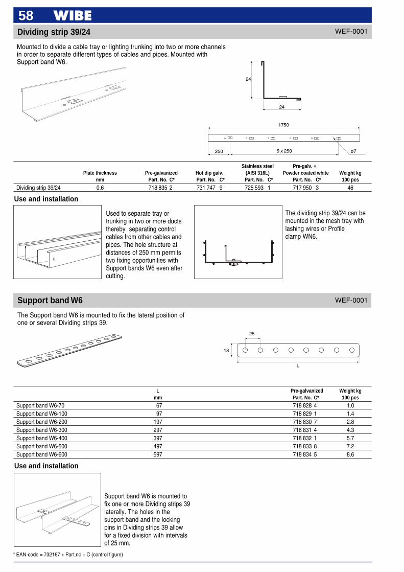
* EAN-code = 732167 + Part.no + C (control figure)
58
Mounted to divide a cable tray or lighting trunking into two or more channelsin order to separate different types of cables and pipes. Mounted withSupport band W6.
Support band W6
The Support band W6 is mounted to fix the lateral position ofone or several Dividing strips 39.
Use and installation
Used to separate tray ortrunking in two or more ductsthereby separating controlcables from other cables andpipes. The hole structure atdistances of 250 mm permitstwo fixing opportunities withSupport bands W6 even aftercutting.
The dividing strip 39/24 can bemounted in the mesh tray withlashing wires or Profileclamp WN6.
WEF-0001
Use and installation
Support band W6 is mounted tofix one or more Dividing strips 39laterally. The holes in thesupport band and the lockingpins in Dividing strips 39 allowfor a fixed division with intervalsof 25 mm.
L
25
18
L Pre-galvanized Weight kgmm Part. No. C* 100 pcs
Support band W6-70 67 718 828 4 1.0Support band W6-100 97 718 829 1 1.4Support band W6-200 197 718 830 7 2.8Support band W6-300 297 718 831 4 4.3Support band W6-400 397 718 832 1 5.7Support band W6-500 497 718 833 8 7.2Support band W6-600 597 718 834 5 8.6
Dividing strip 39/24 WEF-0001
Stainless steel Pre-galv. +Plate thickness Pre-galvanized Hot dip galv. (AISI 316L) Powder coated white Weight kg
mm Part. No. C* Part. No. C* Part. No. C* Part. No. C* 100 pcs
Dividing strip 39/24 0.6 718 835 2 731 747 9 725 593 1 717 950 3 46
24
24
250
1750
5 x 250 ø7
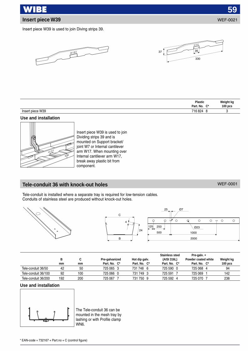
* EAN-code = 732167 + Part.no + C (control figure)
59
Tele-conduit is installed where a separate tray is required for low-tension cables.Conduits of stainless steel are produced without knock-out holes.
Tele-conduit 36 with knock-out holes
Use and installation
330
37 35
Insert piece W39 is used to joinDividing strips 39 and ismounted on Support bracket/joint W7 or Internal cantileverarm W17. When mounting overInternal cantilever arm W17,break away plastic bit fromcomponent.
C
4
24
B
25
250
500
2000
1000
Ø23
Ø7
125
Plastic Weight kgPart. No. C* 100 pcs
Insert piece W39 716 824 8 3
WEF-0001
Use and installation
The Tele-conduit 36 can bemounted in the mesh tray bylashing or with Profile clampWN6.
Insert piece W39 WEF-0021
Insert piece W39 is used to join Diving strips 39.
Stainless steel Pre-galv. +B C Pre-galvanized Hot dip galv. (AISI 316L) Powder coated white Weight kg
mm mm Part. No. C* Part. No. C* Part. No. C* Part. No. C* 100 pcs
Tele-conduit 36/50 42 50 725 065 3 731 748 6 725 590 0 725 068 4 94Tele-conduit 36/100 92 100 725 066 0 731 749 3 725 591 7 725 069 1 142Tele-conduit 36/200 192 200 725 067 7 731 750 9 725 592 4 725 070 7 238
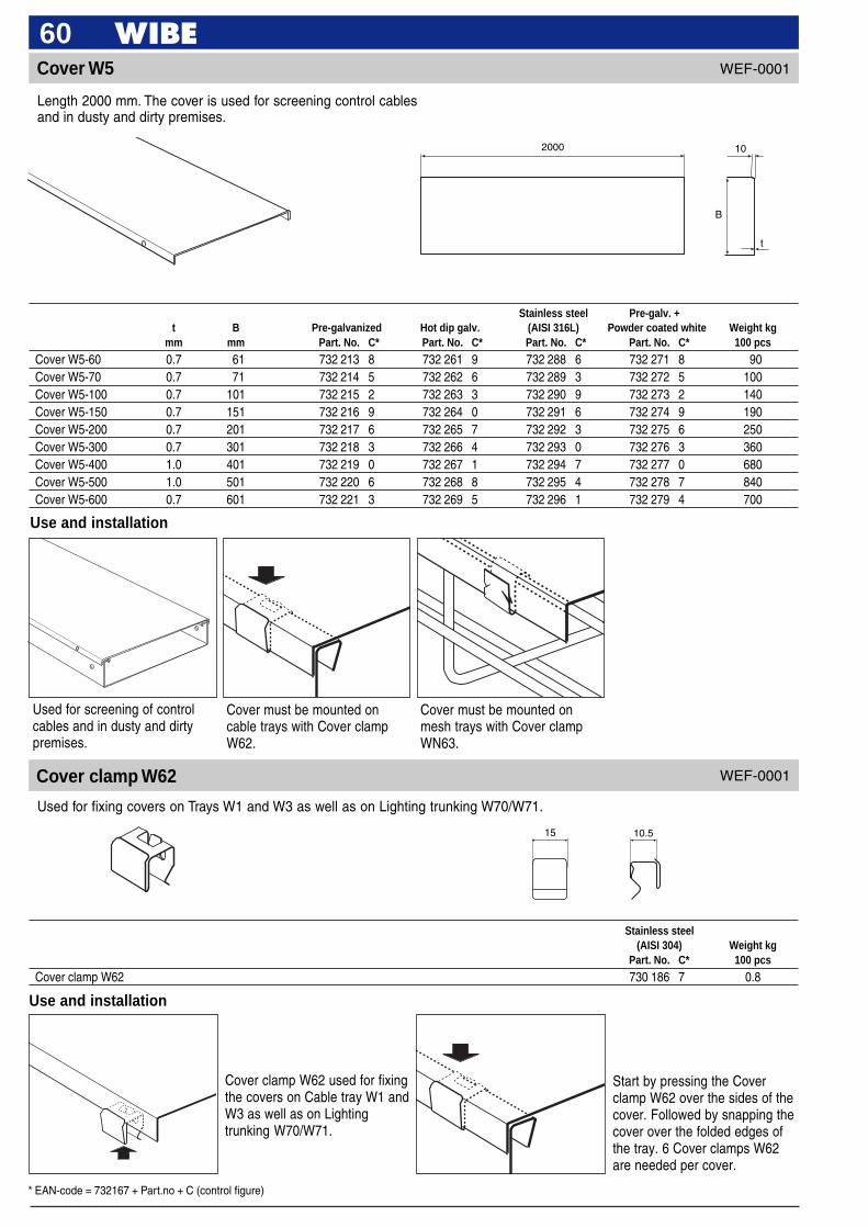
* EAN-code = 732167 + Part.no + C (control figure)
60Cover W5
Use and installation
Used for screening of controlcables and in dusty and dirtypremises.
Cover must be mounted oncable trays with Cover clampW62.
Cover must be mounted onmesh trays with Cover clampWN63.
Length 2000 mm. The cover is used for screening control cablesand in dusty and dirty premises.
Stainless steel Pre-galv. +t B Pre-galvanized Hot dip galv. (AISI 316L) Powder coated white Weight kg
mm mm Part. No. C* Part. No. C* Part. No. C* Part. No. C* 100 pcs
Cover W5-60 0.7 61 732 213 8 732 261 9 732 288 6 732 271 8 90Cover W5-70 0.7 71 732 214 5 732 262 6 732 289 3 732 272 5 100Cover W5-100 0.7 101 732 215 2 732 263 3 732 290 9 732 273 2 140Cover W5-150 0.7 151 732 216 9 732 264 0 732 291 6 732 274 9 190Cover W5-200 0.7 201 732 217 6 732 265 7 732 292 3 732 275 6 250Cover W5-300 0.7 301 732 218 3 732 266 4 732 293 0 732 276 3 360Cover W5-400 1.0 401 732 219 0 732 267 1 732 294 7 732 277 0 680Cover W5-500 1.0 501 732 220 6 732 268 8 732 295 4 732 278 7 840Cover W5-600 0.7 601 732 221 3 732 269 5 732 296 1 732 279 4 700
2000
B
10
t
15 10.5
Stainless steel(AISI 304) Weight kg
Part. No. C* 100 pcs
Cover clamp W62 730 186 7 0.8
Cover clamp W62
Used for fixing covers on Trays W1 and W3 as well as on Lighting trunking W70/W71.
WEF-0001
Cover clamp W62 used for fixingthe covers on Cable tray W1 andW3 as well as on Lightingtrunking W70/W71.
Start by pressing the Coverclamp W62 over the sides of thecover. Followed by snapping thecover over the folded edges ofthe tray. 6 Cover clamps W62are needed per cover.
WEF-0001
Use and installation
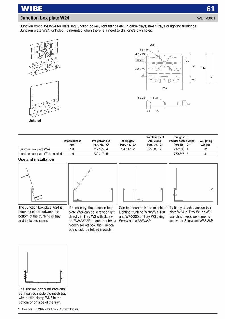
* EAN-code = 732167 + Part.no + C (control figure)
61Junction box plate W24
Junction box plate W24 for installing junction boxes, light fittings etc. in cable trays, mesh trays or lighting trunkings.Junction plate W24, unholed, is mounted when there is a need to drill one’s own holes.
Unholed
Stainless steel Pre-galv. +Plate thickness Pre-galvanized Hot dip galv. (AISI 316L) Powder coated white Weight kg
mm Part. No. C* Part. No. C* Part. No. C* Part. No. C* 100 pcs
Junction box plate W24 1.0 717 995 4 734 617 2 725 588 7 717 996 1 31Junction box plate W24, unholed 1.0 730 247 5 730 248 2 31
The junction box plate W24 canbe mounted inside the mesh traywith profile clamp WN6 in thebottom or on side of the tray.
Use and installation
The Junction box plate W24 ismounted either between thebottom of the trunking or trayand its folded seam.
If necessary, the Junction boxplate W24 can be screwed tightdirectly in Tray W3 with Screwset W38/W38P. If one requires ahidden socket box, the junctionbox should be folded inwards.
Can be mounted in the middle ofLighting trunking W70/W71-100and W70-200 or Tray W3 usingScrew set W38/W38P.
To firmly attach Junction boxplate W24 in Tray W1 or W3,use blind rivets, self-tappingscrews or Screw set W38/38P.
Ø6
25
4.6 x 25
9 x 256 x 25
4.6 x 15
4.6 x 50
Ø5
4.6 x 40
75
43
125
29
29
200
144
WEF-0001
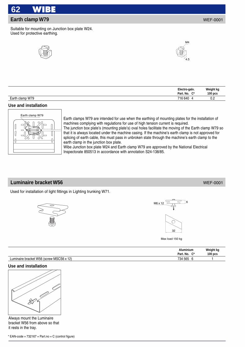
* EAN-code = 732167 + Part.no + C (control figure)
62Earth clamp W79
Use and installation
4.5
M4
Earth clamps W79 are intended for use when the earthing of mounting plates for the installation ofmachines complying with regulations for use of high tension current is required.The junction box plate’s (mounting plate’s) oval holes facilitate the moving of the Earth clamp W79 sothat it is always located under the machine casing. If the machine’s earth clamp is not approved forsplicing of earth cable, this must pass in unbroken state through the machine’s earth clamp to theearth clamp in the junction box plate.Wibe Junction box plate W24 and Earth clamp W79 are approved by the National ElectricalInspectorate 850513 in accordance with annotation S24-138/85.
Luminaire bracket W56
Electro-galv. Weight kgPart. No. C* 100 pcs
Earth clamp W79 716 640 4 0.2
Earth clamp W79
Suitable for mounting on Junction box plate W24.Used for protective earthing.
Used for installation of light fittings in Lighting trunking W71.
Aluminium Weight kgPart. No. C* 100 pcs
Luminaire bracket W56 (screw MSCS6 x 12) 734 565 6 1
Use and installation
Always mount the Luminairebracket W56 from above so thatit rests in the tray.
WEF-0001
WEF-0001
M6 x 12
32
6
Max load 150 kg

* EAN-code = 732167 + Part.no + C (control figure)
63WEF-0001 Luminaire bracket W55
Used for mounting of light fittings under Lighting trunking W70/W71.
Use and installation
Mounted in the mounting holesin Lighting trunking W70/W71.
Always mount the Luminairebracket W55 from above so thatit rests in the tray.
Luminaire bracket W35
Use and installation
Mounted in the rail’s module holes with Screw set W36 or W34.Note! The fork openings must be mounted in the same direction.
Electro-galv. Weight kgPart. No. C* 100 pcs
Luminaire bracket W55 720 979 8 0.8
Plate thickness Pre-galvanized Weight kgmm Part. No. C* 100 pcs
Luminaire bracket W35 1.5 715 650 4 3
For mounting of strip lighting centred under a Lighting trunking W70/W71.Use Screw set W36 or W34.
WEF-0001
15
9
Ø9
30
30
1540
30
M5 x 16
Max. load 50 kg
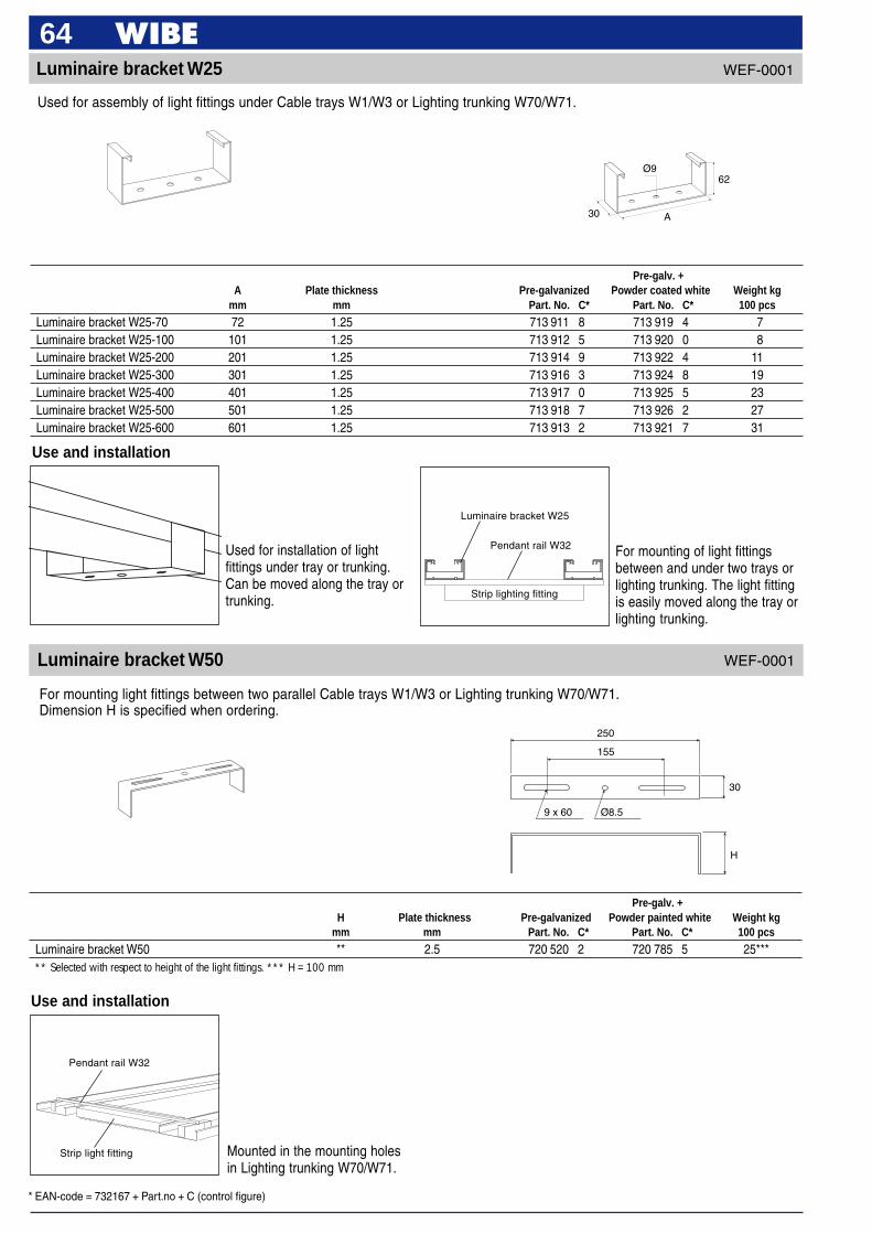
* EAN-code = 732167 + Part.no + C (control figure)
64
Luminaire bracket W50
For mounting light fittings between two parallel Cable trays W1/W3 or Lighting trunking W70/W71.Dimension H is specified when ordering.
250
155
9 x 60 Ø8.5
H
30
Luminaire bracket W25
Used for installation of lightfittings under tray or trunking.Can be moved along the tray ortrunking.
Luminaire bracket W25
For mounting of light fittingsbetween and under two trays orlighting trunking. The light fittingis easily moved along the tray orlighting trunking.
Use and installation
Use and installation
Pre-galv. +A Plate thickness Pre-galvanized Powder coated white Weight kg
mm mm Part. No. C* Part. No. C* 100 pcs
Luminaire bracket W25-70 72 1.25 713 911 8 713 919 4 7Luminaire bracket W25-100 101 1.25 713 912 5 713 920 0 8Luminaire bracket W25-200 201 1.25 713 914 9 713 922 4 11Luminaire bracket W25-300 301 1.25 713 916 3 713 924 8 19Luminaire bracket W25-400 401 1.25 713 917 0 713 925 5 23Luminaire bracket W25-500 501 1.25 713 918 7 713 926 2 27Luminaire bracket W25-600 601 1.25 713 913 2 713 921 7 31
Strip lighting fitting
Pendant rail W32
Mounted in the mounting holesin Lighting trunking W70/W71.
Pendant rail W32
Strip light fitting
Pre-galv. +H Plate thickness Pre-galvanized Powder painted white Weight kg
mm mm Part. No. C* Part. No. C* 100 pcs
Luminaire bracket W50 ** 2.5 720 520 2 720 785 5 25***** Selected with respect to height of the light fittings. *** H = 100 mm
Used for assembly of light fittings under Cable trays W1/W3 or Lighting trunking W70/W71.
WEF-0001
WEF-0001
Ø962
A30
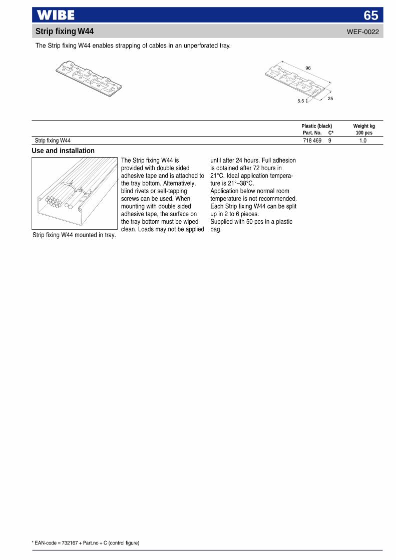
* EAN-code = 732167 + Part.no + C (control figure)
65WEF-0022Strip fixing W44
The Strip fixing W44 enables strapping of cables in an unperforated tray.
Use and installation
25
96
5.5
Plastic (black) Weight kgPart. No. C* 100 pcs
Strip fixing W44 718 469 9 1.0
The Strip fixing W44 isprovided with double sidedadhesive tape and is attached tothe tray bottom. Alternatively,blind rivets or self-tappingscrews can be used. Whenmounting with double sidedadhesive tape, the surface onthe tray bottom must be wipedclean. Loads may not be applied
until after 24 hours. Full adhesionis obtained after 72 hours in21°C. Ideal application tempera-ture is 21°–38°C.Application below normal roomtemperature is not recommended.Each Strip fixing W44 can be splitup in 2 to 6 pieces.Supplied with 50 pcs in a plasticbag.
Strip fixing W44 mounted in tray.

* EAN-code = 732167 + Part.no + C (control figure)
66End plug 7
Fits Vertical piece 7 and Pendant/Fixing rail 7.
Mount End plug 28E for Verticalpiece 2F to provide protectionagainst injury. Fits Vertical piece2F and Pendant/Fixing rail24/48.
Mount End plug 28D for Verticalpiece 20 in the end of thependant to provide protectionagainst injury. Fits Vertical piece20 and Pendant/Fixing rail24/20.
Orange plastic Weight kgPart. No. C* 100 pcs
End plug 28E 709 021 1 0.5End plug 28D 709 020 4 1
WEF-0014
Polyamide (PA) Red Weight kgPart. No. C* 100 pcs
End plug 7 730 178 2 1.5
End plug 7 must always be usedat the cut end of Vertical piece 7or Pendant/Fixing rail 7.
Use and installation
28E 28D
Use and installation
End plug 28E and 28D
Fitted to protect against personal injury.
WEF-0003
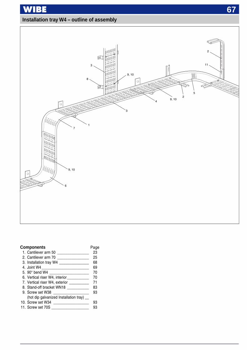
67
1
9, 10
3
7
49, 10
6
3
2
8
5
2
11
Installation tray W4 – outline of assembly
Components Page1. Cantilever arm 50 ________________ 232. Cantilever arm 70 ________________ 253. Installation tray W4 _______________ 684. Joint W4 ________________________ 695. 90° bend W4 ____________________ 706. Vertical riser W4, interior ___________ 707. Vertical riser W4, exterior __________ 718. Stand-off bracket WN18 ___________ 839. Screw set W38 __________________ 93
(hot dip galvanized Installation tray) __10. Screw set W34 __________________ 9311. Screw set 70S ___________________ 93
9, 10
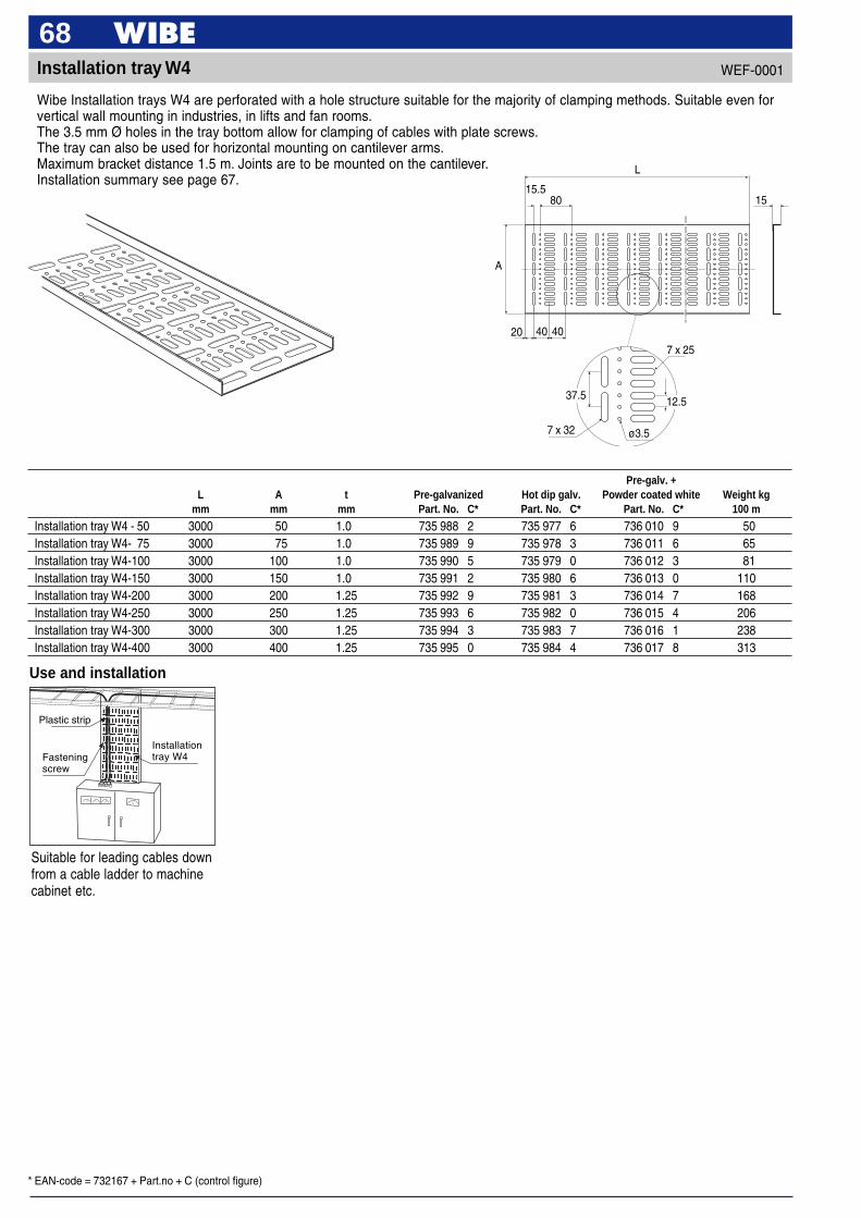
* EAN-code = 732167 + Part.no + C (control figure)
68Installation tray W4
Wibe Installation trays W4 are perforated with a hole structure suitable for the majority of clamping methods. Suitable even forvertical wall mounting in industries, in lifts and fan rooms.The 3.5 mm Ø holes in the tray bottom allow for clamping of cables with plate screws.The tray can also be used for horizontal mounting on cantilever arms.Maximum bracket distance 1.5 m. Joints are to be mounted on the cantilever.Installation summary see page 67.
Use and installation
Plastic strip
Fasteningscrew
Pre-galv. +L A t Pre-galvanized Hot dip galv. Powder coated white Weight kg
mm mm mm Part. No. C* Part. No. C* Part. No. C* 100 m
Installation tray W4 - 50 3000 50 1.0 735 988 2 735 977 6 736 010 9 50Installation tray W4- 75 3000 75 1.0 735 989 9 735 978 3 736 011 6 65Installation tray W4-100 3000 100 1.0 735 990 5 735 979 0 736 012 3 81Installation tray W4-150 3000 150 1.0 735 991 2 735 980 6 736 013 0 110Installation tray W4-200 3000 200 1.25 735 992 9 735 981 3 736 014 7 168Installation tray W4-250 3000 250 1.25 735 993 6 735 982 0 736 015 4 206Installation tray W4-300 3000 300 1.25 735 994 3 735 983 7 736 016 1 238Installation tray W4-400 3000 400 1.25 735 995 0 735 984 4 736 017 8 313
Suitable for leading cables downfrom a cable ladder to machinecabinet etc.
Installationtray W4
WEF-0001
20 40 40
15.580
7 x 32
7 x 25
ø3.5
A
15
37.5 12.5
L

* EAN-code = 732167 + Part.no + C (control figure)
69Joint W4
Used for joining Tray W4.Mounted inside pre-galvanizedor powder coated trays with twoScrew sets W34. Use two Screwsets W38 in hot dip galvanizedtrays.To be mounted on cantileverarm.
Use and installation
Screw set W34
For joining of Installation tray W4.
Pre-galv. +A Plate thickness Pre-galvanized Hot dip galv. Powder coated white Weight kg
mm mm Part. No. C* Part. No. C* Part. No. C* 100 pcs
Joint W4-50 45 1.0 724 949 7 724 918 3 724 957 2 6Joint W4-75 70 1.0 724 950 3 724 919 0 724 958 9 9Joint W4-100 95 1.0 724 951 0 724 920 6 724 959 6 12Joint W4-150 145 1.0 724 952 7 724 921 3 724 960 2 18Joint W4-200 195 1.25 724 953 4 724 922 0 724 961 9 31Joint W4-250 245 1.25 724 954 1 724 923 7 724 962 6 40Joint W4-300 295 1.25 724 955 8 724 924 4 724 963 3 47Joint W4-400 395 1.25 724 956 5 724 925 1 724 964 0 62
WEF-0001
A
200
7 x 32 7 x 25ø3.5
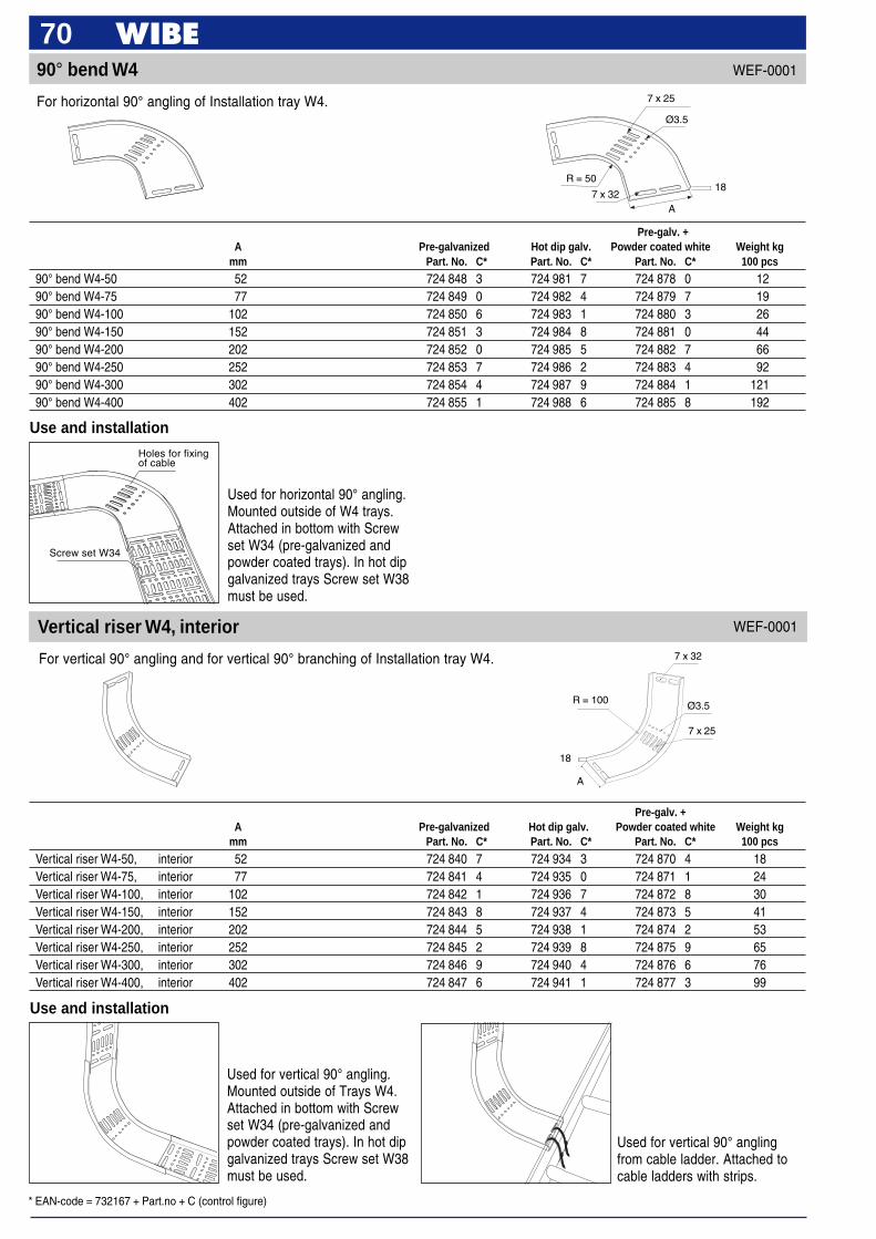
* EAN-code = 732167 + Part.no + C (control figure)
70
7 x 32
Ø3.5
7 x 25
R = 100
A
18
Pre-galv. +A Pre-galvanized Hot dip galv. Powder coated white Weight kg
mm Part. No. C* Part. No. C* Part. No. C* 100 pcs
Vertical riser W4-50, interior 52 724 840 7 724 934 3 724 870 4 18Vertical riser W4-75, interior 77 724 841 4 724 935 0 724 871 1 24Vertical riser W4-100, interior 102 724 842 1 724 936 7 724 872 8 30Vertical riser W4-150, interior 152 724 843 8 724 937 4 724 873 5 41Vertical riser W4-200, interior 202 724 844 5 724 938 1 724 874 2 53Vertical riser W4-250, interior 252 724 845 2 724 939 8 724 875 9 65Vertical riser W4-300, interior 302 724 846 9 724 940 4 724 876 6 76Vertical riser W4-400, interior 402 724 847 6 724 941 1 724 877 3 99
Ø3.5
7 x 25
R = 50
7 x 32A
18
90° bend W4
Use and installation
Used for horizontal 90° angling.Mounted outside of W4 trays.Attached in bottom with Screwset W34 (pre-galvanized andpowder coated trays). In hot dipgalvanized trays Screw set W38must be used.
Pre-galv. +A Pre-galvanized Hot dip galv. Powder coated white Weight kg
mm Part. No. C* Part. No. C* Part. No. C* 100 pcs
90° bend W4-50 52 724 848 3 724 981 7 724 878 0 1290° bend W4-75 77 724 849 0 724 982 4 724 879 7 1990° bend W4-100 102 724 850 6 724 983 1 724 880 3 2690° bend W4-150 152 724 851 3 724 984 8 724 881 0 4490° bend W4-200 202 724 852 0 724 985 5 724 882 7 6690° bend W4-250 252 724 853 7 724 986 2 724 883 4 9290° bend W4-300 302 724 854 4 724 987 9 724 884 1 12190° bend W4-400 402 724 855 1 724 988 6 724 885 8 192
Holes for fixingof cable
Screw set W34
For horizontal 90° angling of Installation tray W4.
WEF-0001
Vertical riser W4, interior
For vertical 90° angling and for vertical 90° branching of Installation tray W4.
WEF-0001
Used for vertical 90° angling.Mounted outside of Trays W4.Attached in bottom with Screwset W34 (pre-galvanized andpowder coated trays). In hot dipgalvanized trays Screw set W38must be used.
Use and installation
Used for vertical 90° anglingfrom cable ladder. Attached tocable ladders with strips.
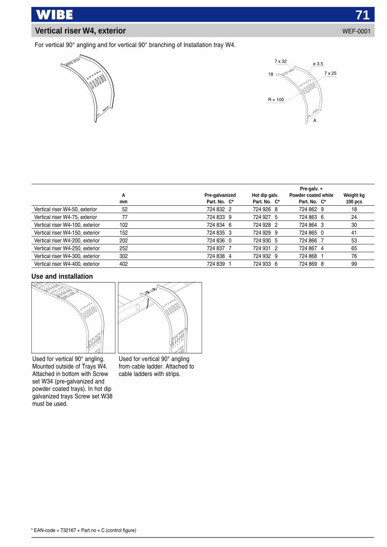
* EAN-code = 732167 + Part.no + C (control figure)
71Vertical riser W4, exterior
ø 3.57 x 32
7 x 2518
R = 100
A
Use and installation
Used for vertical 90° angling.Mounted outside of Trays W4.Attached in bottom with Screwset W34 (pre-galvanized andpowder coated trays). In hot dipgalvanized trays Screw set W38must be used.
Used for vertical 90° anglingfrom cable ladder. Attached tocable ladders with strips.
Pre-galv. +A Pre-galvanized Hot dip galv. Powder coated white Weight kg
mm Part. No. C* Part. No. C* Part. No. C* 100 pcs
Vertical riser W4-50, exterior 52 724 832 2 724 926 8 724 862 9 18Vertical riser W4-75, exterior 77 724 833 9 724 927 5 724 863 6 24Vertical riser W4-100, exterior 102 724 834 6 724 928 2 724 864 3 30Vertical riser W4-150, exterior 152 724 835 3 724 929 9 724 865 0 41Vertical riser W4-200, exterior 202 724 836 0 724 930 5 724 866 7 53Vertical riser W4-250, exterior 252 724 837 7 724 931 2 724 867 4 65Vertical riser W4-300, exterior 302 724 838 4 724 932 9 724 868 1 76Vertical riser W4-400, exterior 402 724 839 1 724 933 6 724 869 8 99
For vertical 90° angling and for vertical 90° branching of Installation tray W4.
WEF-0001

72Mesh trays – Installation summary
36
31, 3210
76
8
3451
31, 3213
9
49
11
33
35
31, 32
35
48
4
3
45
2921
30
50 3
51
47
1929
5
15
5030
30
4242
31
3438
41
42
38
41
46
16
17
28
40
34
55
12
30
24
Tube pendant attachment W73
Threaded rod M10 W76
Joint nut M10
Joint nut M10 W76
Nut M10
Base clamp WN4
Nut M10
Vertical piece 2F
Angle bracket W8S
Support bracket WN5
Ceiling bracket 5
Pendant/Fixing rail24/34
Angle bracket W8S
Support bracket WN5
15
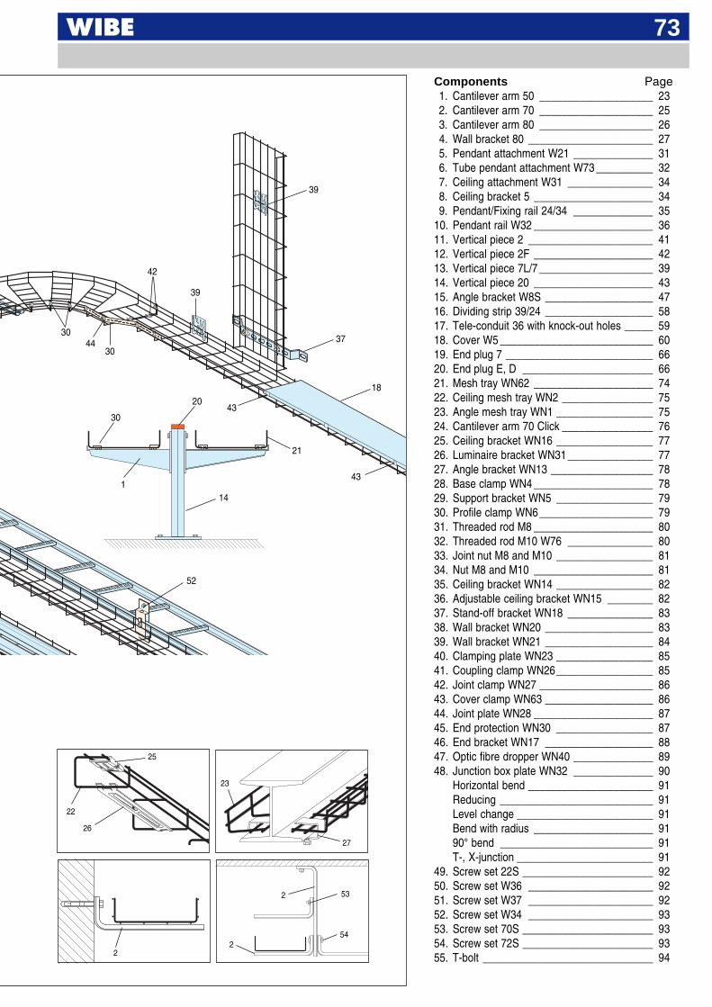
73
Components Page1. Cantilever arm 50 ____________________ 232. Cantilever arm 70 ____________________ 253. Cantilever arm 80 ____________________ 264. Wall bracket 80 ______________________ 275. Pendant attachment W21 ______________ 316. Tube pendant attachment W73 __________ 327. Ceiling attachment W31 _______________ 348. Ceiling bracket 5 _____________________ 349. Pendant/Fixing rail 24/34 ______________ 35
10. Pendant rail W32 _____________________ 3611. Vertical piece 2 ______________________ 4112. Vertical piece 2F _____________________ 4213. Vertical piece 7L/7 ____________________ 3914. Vertical piece 20 _____________________ 4315. Angle bracket W8S ___________________ 4716. Dividing strip 39/24 ___________________ 5817. Tele-conduit 36 with knock-out holes _____ 5918. Cover W5 ___________________________ 6019. End plug 7 __________________________ 6620. End plug E, D _______________________ 6621. Mesh tray WN62 _____________________ 7422. Ceiling mesh tray WN2 ________________ 7523. Angle mesh tray WN1 _________________ 7524. Cantilever arm 70 Click ________________ 7625. Ceiling bracket WN16 _________________ 7726. Luminaire bracket WN31 _______________ 7727. Angle bracket WN13 __________________ 7828. Base clamp WN4 _____________________ 7829. Support bracket WN5 _________________ 7930. Profile clamp WN6____________________ 7931. Threaded rod M8 _____________________ 8032. Threaded rod M10 W76 _______________ 8033. Joint nut M8 and M10 _________________ 8134. Nut M8 and M10 _____________________ 8135. Ceiling bracket WN14 _________________ 8236. Adjustable ceiling bracket WN15 ________ 8237. Stand-off bracket WN18 _______________ 8338. Wall bracket WN20 ___________________ 8339. Wall bracket WN21 ___________________ 8440. Clamping plate WN23 _________________ 8541. Coupling clamp WN26_________________ 8542. Joint clamp WN27 ____________________ 8643. Cover clamp WN63 ___________________ 8644. Joint plate WN28 _____________________ 8745. End protection WN30 _________________ 8746. End bracket WN17 ___________________ 8847. Optic fibre dropper WN40 ______________ 8948. Junction box plate WN32 ______________ 90
Horizontal bend ______________________ 91Reducing ___________________________ 91Level change ________________________ 91Bend with radius _____________________ 9190° bend ___________________________ 91T-, X-junction ________________________ 91
49. Screw set 22S _______________________ 9250. Screw set W36 ______________________ 9251. Screw set W37 ______________________ 9252. Screw set W34 ______________________ 9353. Screw set 70S _______________________ 9354. Screw set 72S _______________________ 9355. T-bolt ______________________________ 94
30
42
44
39
30
18
37
39
43
14
30
1
21
20
2 53
542
2
23
27
25
26
22
52
43
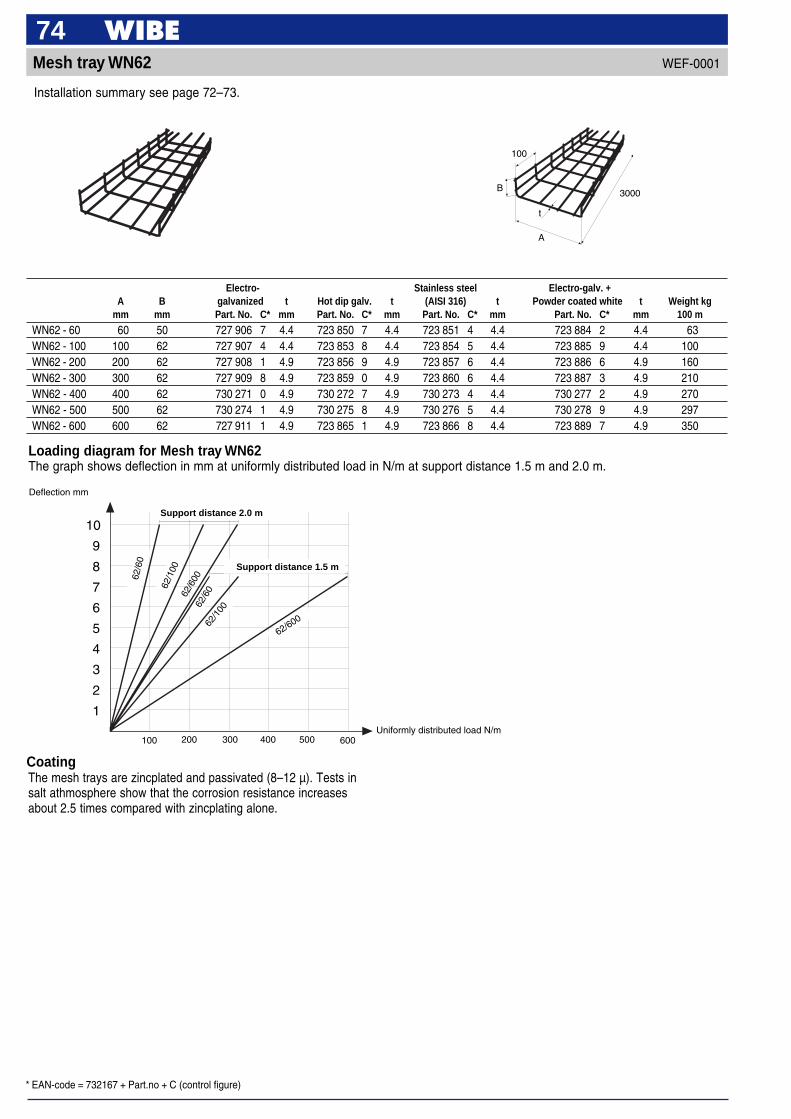
* EAN-code = 732167 + Part.no + C (control figure)
74Mesh tray WN62
Installation summary see page 72–73.
Loading diagram for Mesh tray WN62The graph shows deflection in mm at uniformly distributed load in N/m at support distance 1.5 m and 2.0 m.
Deflection mm
62/6
0
62/1
00
62/1
00
62/6
0062
/60
62/600
Support distance 2.0 m
Support distance 1.5 m
10
9
8
7
6
5
4
3
2
1
100 200 300 400 500 600Uniformly distributed load N/m
Electro- Stainless steel Electro-galv. +A B galvanized t Hot dip galv. t (AISI 316) t Powder coated white t Weight kg
mm mm Part. No. C* mm Part. No. C* mm Part. No. C* mm Part. No. C* mm 100 m
WN62 - 60 60 50 727 906 7 4.4 723 850 7 4.4 723 851 4 4.4 723 884 2 4.4 63WN62 - 100 100 62 727 907 4 4.4 723 853 8 4.4 723 854 5 4.4 723 885 9 4.4 100WN62 - 200 200 62 727 908 1 4.9 723 856 9 4.9 723 857 6 4.4 723 886 6 4.9 160WN62 - 300 300 62 727 909 8 4.9 723 859 0 4.9 723 860 6 4.4 723 887 3 4.9 210WN62 - 400 400 62 730 271 0 4.9 730 272 7 4.9 730 273 4 4.4 730 277 2 4.9 270WN62 - 500 500 62 730 274 1 4.9 730 275 8 4.9 730 276 5 4.4 730 278 9 4.9 297WN62 - 600 600 62 727 911 1 4.9 723 865 1 4.9 723 866 8 4.4 723 889 7 4.9 350
CoatingThe mesh trays are zincplated and passivated (8–12 µ). Tests insalt athmosphere show that the corrosion resistance increasesabout 2.5 times compared with zincplating alone.
WEF-0001
A
3000B
t
100
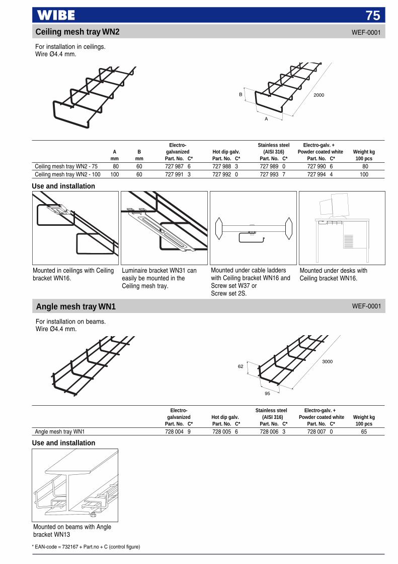
* EAN-code = 732167 + Part.no + C (control figure)
75Ceiling mesh tray WN2
Use and installation
Angle mesh tray WN1
B
A
2000
95
300062
Mounted on beams with Anglebracket WN13
Use and installation
Mounted in ceilings with Ceilingbracket WN16.
Electro- Stainless steel Electro-galv. +A B galvanized Hot dip galv. (AISI 316) Powder coated white Weight kg
mm mm Part. No. C* Part. No. C* Part. No. C* Part. No. C* 100 pcs
Ceiling mesh tray WN2 - 75 80 60 727 987 6 727 988 3 727 989 0 727 990 6 80Ceiling mesh tray WN2 - 100 100 60 727 991 3 727 992 0 727 993 7 727 994 4 100
Electro- Stainless steel Electro-galv. +galvanized Hot dip galv. (AISI 316) Powder coated white Weight kg
Part. No. C* Part. No. C* Part. No. C* Part. No. C* 100 pcs
Angle mesh tray WN1 728 004 9 728 005 6 728 006 3 728 007 0 65
For installation in ceilings.Wire Ø4.4 mm.
For installation on beams.Wire Ø4.4 mm.
WEF-0001
WEF-0001
Luminaire bracket WN31 caneasily be mounted in theCeiling mesh tray.
Mounted under cable ladderswith Ceiling bracket WN16 andScrew set W37 orScrew set 2S.
Mounted under desks withCeiling bracket WN16.

* EAN-code = 732167 + Part.no + C (control figure)
76Cantilever arm 70 Click
L Pre-galv. Hot dip galv. Weight kgmm Part. No. C* Part. No. C* 100 pcs
Cantilever arm 70/100 Click 150 735 424 5 735 428 3 40Cantilever arm 70/150 Click 200 735 425 2 735 429 0 47Cantilever arm 70/200 Click 250 735 426 9 735 430 6 53Cantilever arm 70/300 Click 350 735 427 6 735 431 3 65
Loading table for Cantilever arm 70 Click on wall
Cantilever arm 70 Click ismounted on pendant/fixing railor Fixing rail for casting-in withT-bolt 26F-40.
Cantilever arm 70 Click can bemounted as a vertical piece.Use Screw set 70S for mountingof Cantilever arm 70 on verticalpiece.
Cantilever arm 70 Click ismounted on wall with Expansion-shell bolt.
Use and installation
T-bolt
Type of Max load F at 3° deflection Deflection in mm at 3° deflection Breaking loadcantilever arm of cantilever arm of cantilever arm
kN kg kN kg
70/100 Click 1.8 180 7 3.6 36070/200 Click 1.2 120 12 2.4 24070/300 Click 1.0 100 17 2.0 200
F
Screw set70S
L
30 x 11
140
20
50
For Mesh trays WN62.
WEF-0001
100
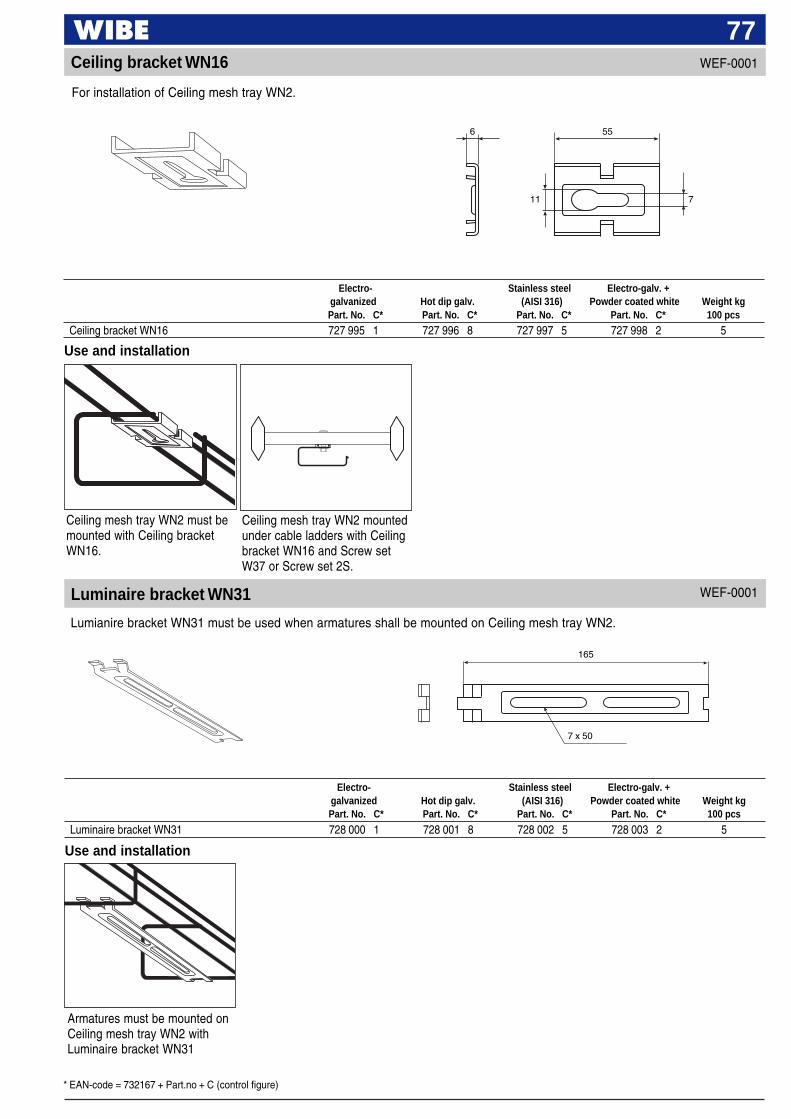
* EAN-code = 732167 + Part.no + C (control figure)
77WEF-0001Ceiling bracket WN16
Luminaire bracket WN31
Use and installation
Use and installation
Ceiling mesh tray WN2 must bemounted with Ceiling bracketWN16.
Armatures must be mounted onCeiling mesh tray WN2 withLuminaire bracket WN31
Electro- Stainless steel Electro-galv. +galvanized Hot dip galv. (AISI 316) Powder coated white Weight kgPart. No. C* Part. No. C* Part. No. C* Part. No. C* 100 pcs
Ceiling bracket WN16 727 995 1 727 996 8 727 997 5 727 998 2 5
Electro- Stainless steel Electro-galv. +galvanized Hot dip galv. (AISI 316) Powder coated white Weight kgPart. No. C* Part. No. C* Part. No. C* Part. No. C* 100 pcs
Luminaire bracket WN31 728 000 1 728 001 8 728 002 5 728 003 2 5
For installation of Ceiling mesh tray WN2.
Lumianire bracket WN31 must be used when armatures shall be mounted on Ceiling mesh tray WN2.
WEF-0001
6 55
7
7 x 50
165
11
Ceiling mesh tray WN2 mountedunder cable ladders with Ceilingbracket WN16 and Screw setW37 or Screw set 2S.
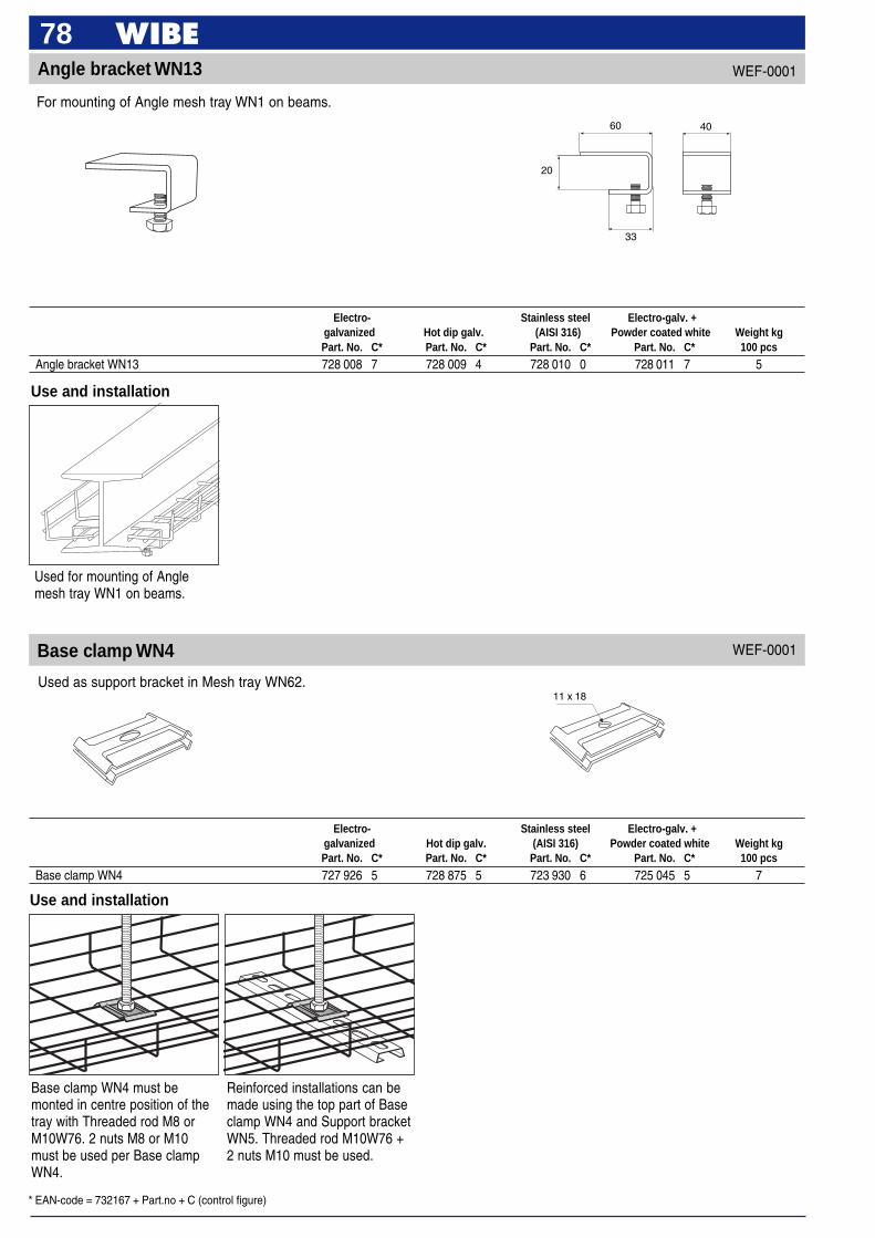
* EAN-code = 732167 + Part.no + C (control figure)
78WEF-0001Angle bracket WN13
Use and installation
Used for mounting of Anglemesh tray WN1 on beams.
Base clamp WN4
60
20
33
40
11 x 18
Use and installation
Base clamp WN4 must bemonted in centre position of thetray with Threaded rod M8 orM10W76. 2 nuts M8 or M10must be used per Base clampWN4.
Reinforced installations can bemade using the top part of Baseclamp WN4 and Support bracketWN5. Threaded rod M10W76 +2 nuts M10 must be used.
Electro- Stainless steel Electro-galv. +galvanized Hot dip galv. (AISI 316) Powder coated white Weight kgPart. No. C* Part. No. C* Part. No. C* Part. No. C* 100 pcs
Angle bracket WN13 728 008 7 728 009 4 728 010 0 728 011 7 5
Electro- Stainless steel Electro-galv. +galvanized Hot dip galv. (AISI 316) Powder coated white Weight kgPart. No. C* Part. No. C* Part. No. C* Part. No. C* 100 pcs
Base clamp WN4 727 926 5 728 875 5 723 930 6 725 045 5 7
For mounting of Angle mesh tray WN1 on beams.
Used as support bracket in Mesh tray WN62.
WEF-0001
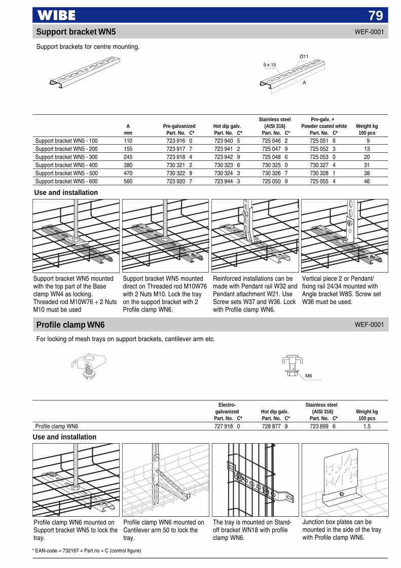
* EAN-code = 732167 + Part.no + C (control figure)
79WEF-0001Support bracket WN5
Use and installation
9 x 15
Ø11
A
Support bracket WN5 mountedwith the top part of the Baseclamp WN4 as locking.Threaded rod M10W76 + 2 NutsM10 must be used
Support bracket WN5 mounteddirect on Threaded rod M10W76with 2 Nuts M10. Lock the trayon the support bracket with 2Profile clamp WN6.
Vertical piece 2 or Pendant/fixing rail 24/34 mounted withAngle bracket W8S. Screw setW36 must be used.
Reinforced installations can bemade with Pendant rail W32 andPendant attachment W21. UseScrew sets W37 and W36. Lockwith Profile clamp WN6.
Profile clamp WN6
Stainless steel Pre-galv. +A Pre-galvanized Hot dip galv. (AISI 316) Powder coated white Weight kg
mm Part. No. C* Part. No. C* Part. No. C* Part. No. C* 100 pcs
Support bracket WN5 - 100 110 723 916 0 723 940 5 725 046 2 725 051 6 9Support bracket WN5 - 200 155 723 917 7 723 941 2 725 047 9 725 052 3 13Support bracket WN5 - 300 245 723 918 4 723 942 9 725 048 6 725 053 0 20Support bracket WN5 - 400 380 730 321 2 730 323 6 730 325 0 730 327 4 31Support bracket WN5 - 500 470 730 322 9 730 324 3 730 326 7 730 328 1 38Support bracket WN5 - 600 560 723 920 7 723 944 3 725 050 9 725 055 4 46
WEF-0001
For locking of mesh trays on support brackets, cantilever arm etc.
Support brackets for centre mounting.
Use and installation
Profile clamp WN6 mounted onSupport bracket WN5 to lock thetray.
The tray is mounted on Stand-off bracket WN18 with profileclamp WN6.
Profile clamp WN6 mounted onCantilever arm 50 to lock thetray.
Junction box plates can bemounted in the side of the traywith Profile clamp WN6.
Electro- Stainless steelgalvanized Hot dip galv. (AISI 316) Weight kgPart. No. C* Part. No. C* Part. No. C* 100 pcs
Profile clamp WN6 727 918 0 728 877 9 723 899 6 1.5
M6

* EAN-code = 732167 + Part.no + C (control figure)
80WEF-0001Threaded rod M8
Use and installation
When uneven loads areexpected on the tray, Threadedrod M8 can be mounted bymeans of Wall bracket WN20 onboth sides of the tray.
Threaded rod M8 must be joinedby Joint nut M8.
Use and installation
The Threaded rod M10 can bemounted in the tray with Baseclamp WN4. 2 Nuts M10 arerequired.
Use Joint nut M10 when joining2 pieces of Threaded rodM10W76.
The Threaded rod M10W76 iscut to the required length andmounted with 2 Tube pendantattachment W73.
Installation directly in concreteceilings using impact anchorEAM10 (10 mm).
Electro- Stainless steelL galvanized (AISI 316) Weight kg
mm Part. No. C* Part. No. C* 100 pcs
Threaded rod M8 - 500 500 725 077 6 725 078 3 16Threaded rod M8 - 1000 1 000 725 079 0 725 080 6 32
When installing in light concreteit is advisable to drill a throughhole and drop the threaded rodM8 straight through. Install withMounting set W78.
Electro- Stainless steel Electro-galv. +L galvanized (AISI 316) Powder coated white Weight kg
mm Part. No. C* Part. No. C* Part. No. C* 100 pcs
Threaded rod M10 W76 - 2000 2 000 716 792 0 723 925 2 718 795 9 100Threaded rod M10 W76 - 3000 3 000 716 793 7 723 926 9 718 797 3 150
Threaded rod M10 W76Delivered in lengths of 2 and 3 m. Cut on site to suitable lengths.
WEF-0001
L
M8
L
M10
Delivered in lengths of 0.5 and 1 m. Cut on site to suitable lengths.
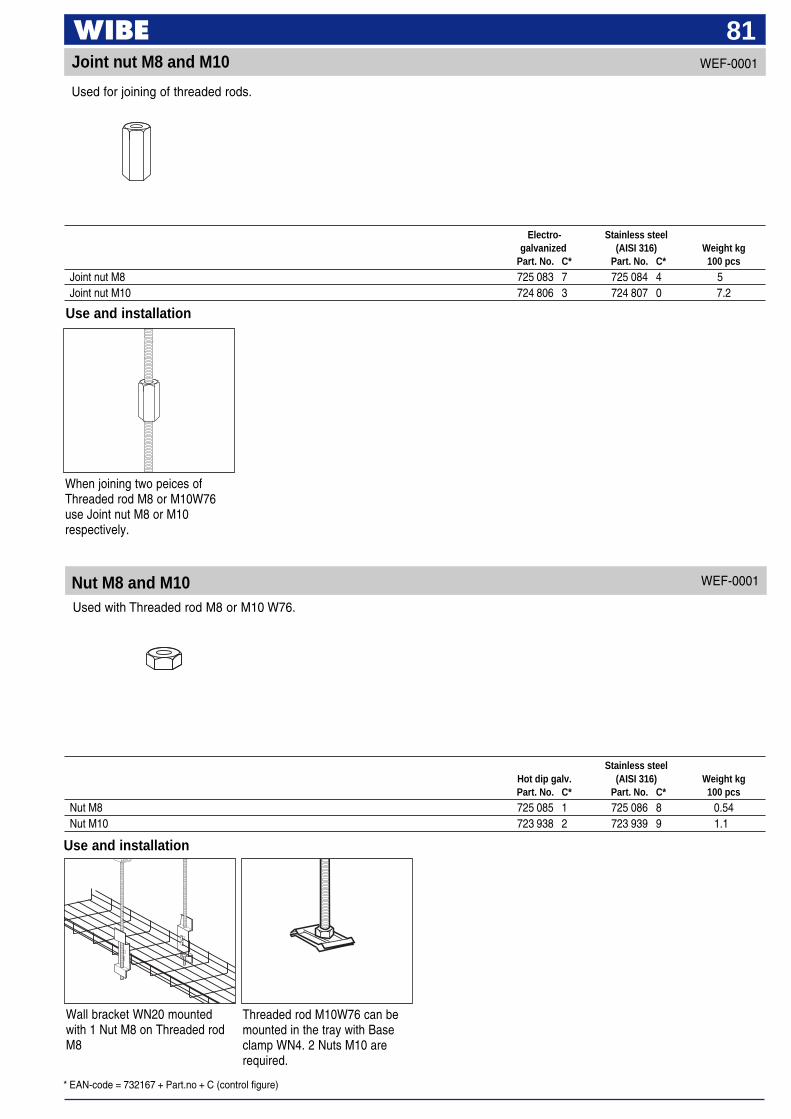
* EAN-code = 732167 + Part.no + C (control figure)
81Joint nut M8 and M10
Use and installation
Wall bracket WN20 mountedwith 1 Nut M8 on Threaded rodM8
Threaded rod M10W76 can bemounted in the tray with Baseclamp WN4. 2 Nuts M10 arerequired.
Use and installation
When joining two peices ofThreaded rod M8 or M10W76use Joint nut M8 or M10respectively.
Electro- Stainless steel galvanized (AISI 316) Weight kgPart. No. C* Part. No. C* 100 pcs
Joint nut M8 725 083 7 725 084 4 5Joint nut M10 724 806 3 724 807 0 7.2
Stainless steelHot dip galv. (AISI 316) Weight kgPart. No. C* Part. No. C* 100 pcs
Nut M8 725 085 1 725 086 8 0.54Nut M10 723 938 2 723 939 9 1.1
Used for joining of threaded rods.
WEF-0001
Nut M8 and M10 WEF-0001
Used with Threaded rod M8 or M10 W76.
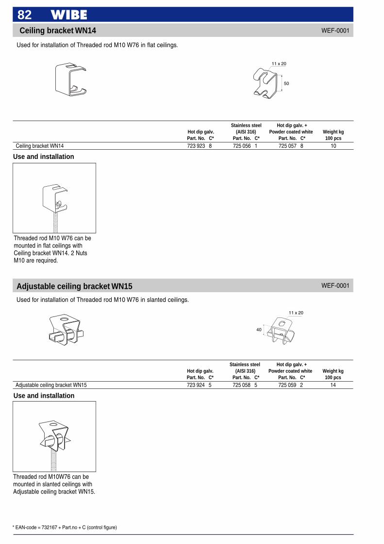
* EAN-code = 732167 + Part.no + C (control figure)
82 Ceiling bracket WN14
Adjustable ceiling bracket WN15
11 x 20
50
40
11 x 20
Use and installation
Threaded rod M10 W76 can bemounted in flat ceilings withCeiling bracket WN14. 2 NutsM10 are required.
Stainless steel Hot dip galv. +Hot dip galv. (AISI 316) Powder coated white Weight kgPart. No. C* Part. No. C* Part. No. C* 100 pcs
Ceiling bracket WN14 723 923 8 725 056 1 725 057 8 10
Stainless steel Hot dip galv. +Hot dip galv. (AISI 316) Powder coated white Weight kgPart. No. C* Part. No. C* Part. No. C* 100 pcs
Adjustable ceiling bracket WN15 723 924 5 725 058 5 725 059 2 14
Use and installation
Threaded rod M10W76 can bemounted in slanted ceilings withAdjustable ceiling bracket WN15.
Used for installation of Threaded rod M10 W76 in flat ceilings.
Used for installation of Threaded rod M10 W76 in slanted ceilings.
WEF-0001
WEF-0001
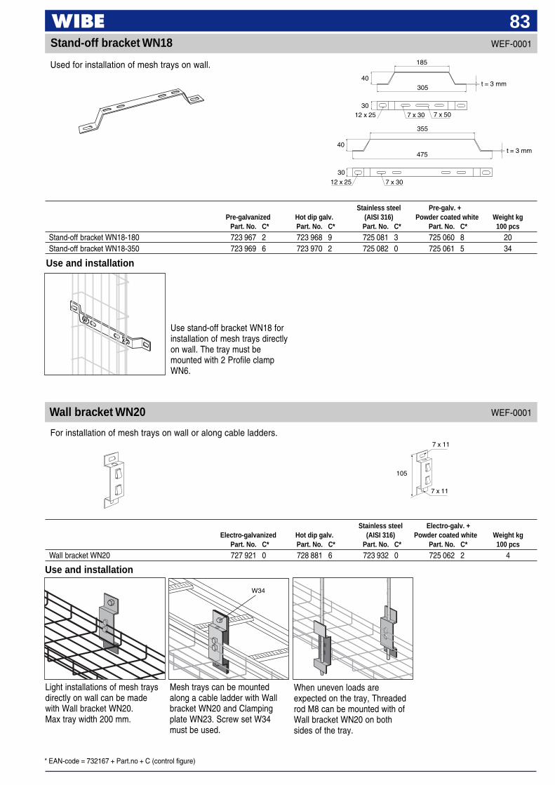
* EAN-code = 732167 + Part.no + C (control figure)
83WEF-0001Stand-off bracket WN18
7 x 11
105
7 x 11
Wall bracket WN20
Use and installation
Use stand-off bracket WN18 forinstallation of mesh trays directlyon wall. The tray must bemounted with 2 Profile clampWN6.
Stainless steel Pre-galv. +Pre-galvanized Hot dip galv. (AISI 316) Powder coated white Weight kg
Part. No. C* Part. No. C* Part. No. C* Part. No. C* 100 pcs
Stand-off bracket WN18-180 723 967 2 723 968 9 725 081 3 725 060 8 20Stand-off bracket WN18-350 723 969 6 723 970 2 725 082 0 725 061 5 34
Used for installation of mesh trays on wall.
WEF-0001
185
7 x 3012 x 25 7 x 50
40305
30
40
355
30
12 x 25
475
7 x 30
t = 3 mm
t = 3 mm
For installation of mesh trays on wall or along cable ladders.
Stainless steel Electro-galv. +Electro-galvanized Hot dip galv. (AISI 316) Powder coated white Weight kg
Part. No. C* Part. No. C* Part. No. C* Part. No. C* 100 pcs
Wall bracket WN20 727 921 0 728 881 6 723 932 0 725 062 2 4
Use and installation
Mesh trays can be mountedalong a cable ladder with Wallbracket WN20 and Clampingplate WN23. Screw set W34must be used.
When uneven loads areexpected on the tray, Threadedrod M8 can be mounted with ofWall bracket WN20 on bothsides of the tray.
Light installations of mesh traysdirectly on wall can be madewith Wall bracket WN20.Max tray width 200 mm.
W34
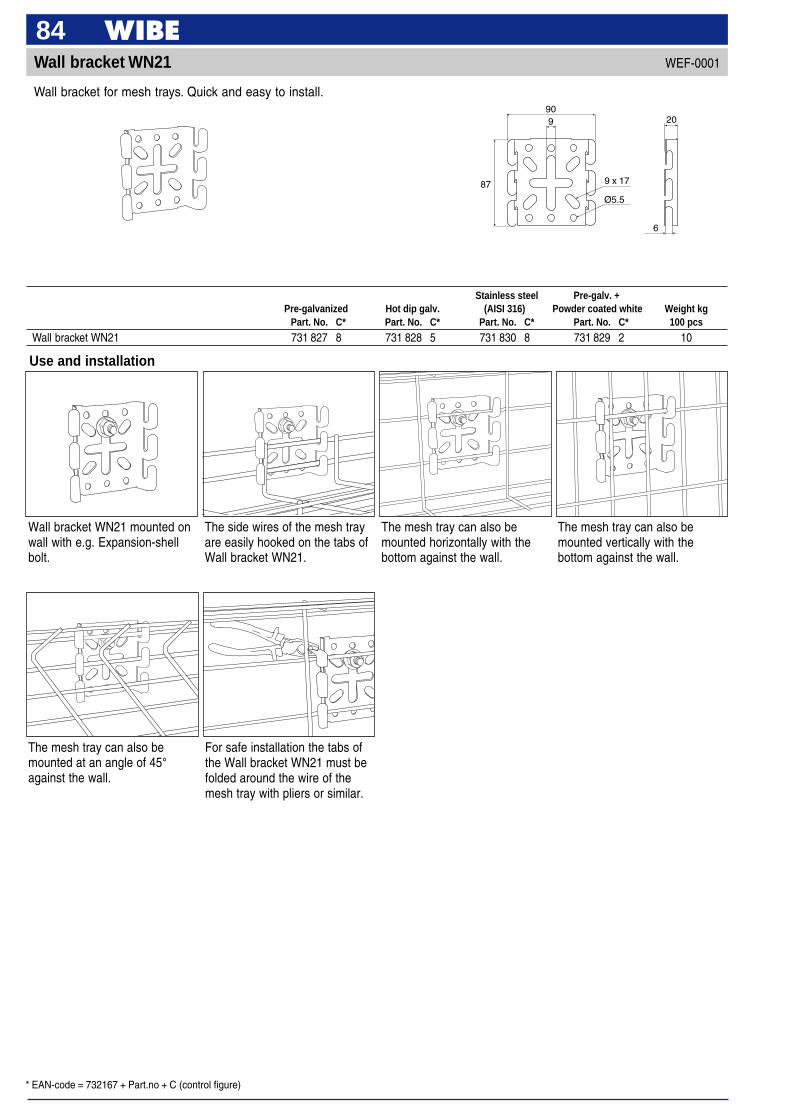
* EAN-code = 732167 + Part.no + C (control figure)
84WEF-0001Wall bracket WN21
90
6
87 9 x 17
209
Ø5.5
Use and installation
The side wires of the mesh trayare easily hooked on the tabs ofWall bracket WN21.
The mesh tray can also bemounted horizontally with thebottom against the wall.
Wall bracket WN21 mounted onwall with e.g. Expansion-shellbolt.
The mesh tray can also bemounted vertically with thebottom against the wall.
Stainless steel Pre-galv. +Pre-galvanized Hot dip galv. (AISI 316) Powder coated white Weight kg
Part. No. C* Part. No. C* Part. No. C* Part. No. C* 100 pcs
Wall bracket WN21 731 827 8 731 828 5 731 830 8 731 829 2 10
Wall bracket for mesh trays. Quick and easy to install.
For safe installation the tabs ofthe Wall bracket WN21 must befolded around the wire of themesh tray with pliers or similar.
The mesh tray can also bemounted at an angle of 45°against the wall.
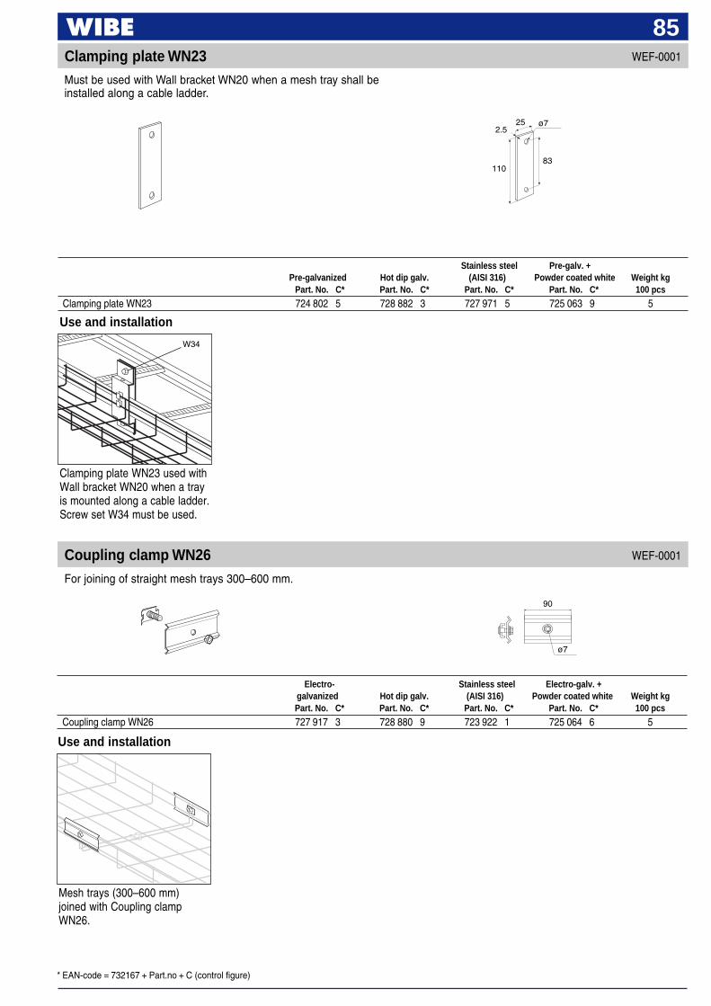
* EAN-code = 732167 + Part.no + C (control figure)
85
Clamping plate WN23 used withWall bracket WN20 when a trayis mounted along a cable ladder.Screw set W34 must be used.
Stainless steel Pre-galv. +Pre-galvanized Hot dip galv. (AISI 316) Powder coated white Weight kg
Part. No. C* Part. No. C* Part. No. C* Part. No. C* 100 pcs
Clamping plate WN23 724 802 5 728 882 3 727 971 5 725 063 9 5
W34
25
83110
ø72.5
Clamping plate WN23 WEF-0001
WEF-0001
Electro- Stainless steel Electro-galv. +galvanized Hot dip galv. (AISI 316) Powder coated white Weight kgPart. No. C* Part. No. C* Part. No. C* Part. No. C* 100 pcs
Coupling clamp WN26 727 917 3 728 880 9 723 922 1 725 064 6 5
Use and installation
Must be used with Wall bracket WN20 when a mesh tray shall beinstalled along a cable ladder.
Coupling clamp WN26For joining of straight mesh trays 300–600 mm.
Use and installation
Mesh trays (300–600 mm)joined with Coupling clampWN26.
90
ø7
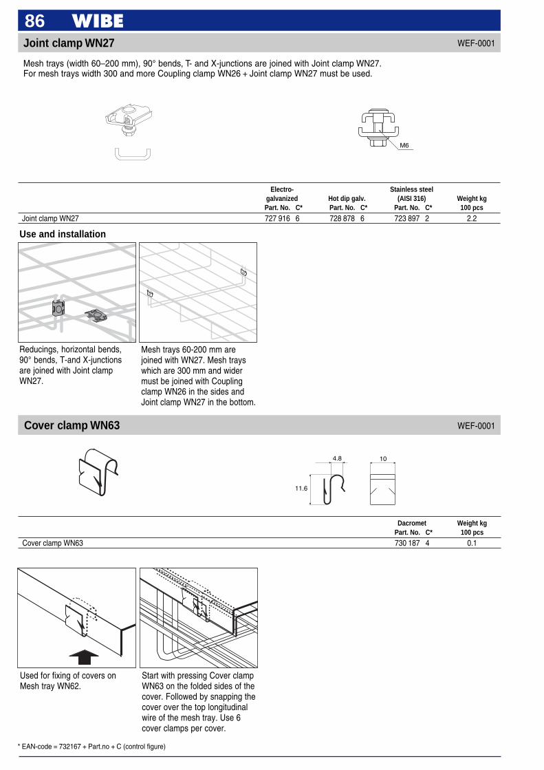
* EAN-code = 732167 + Part.no + C (control figure)
86Joint clamp WN27
Electro- Stainless steelgalvanized Hot dip galv. (AISI 316) Weight kgPart. No. C* Part. No. C* Part. No. C* 100 pcs
Joint clamp WN27 727 916 6 728 878 6 723 897 2 2.2
Mesh trays (width 60–200 mm), 90° bends, T- and X-junctions are joined with Joint clamp WN27.For mesh trays width 300 and more Coupling clamp WN26 + Joint clamp WN27 must be used.
WEF-0001
M6
Use and installation
Reducings, horizontal bends,90° bends, T-and X-junctionsare joined with Joint clampWN27.
Mesh trays 60-200 mm arejoined with WN27. Mesh trayswhich are 300 mm and widermust be joined with Couplingclamp WN26 in the sides andJoint clamp WN27 in the bottom.
Dacromet Weight kgPart. No. C* 100 pcs
Cover clamp WN63 730 187 4 0.1
WEF-0001
Used for fixing of covers onMesh tray WN62.
Start with pressing Cover clampWN63 on the folded sides of thecover. Followed by snapping thecover over the top longitudinalwire of the mesh tray. Use 6cover clamps per cover.
4.8
11.6
10
Cover clamp WN63

* EAN-code = 732167 + Part.no + C (control figure)
87Joint plate WN28
300
7 x 28
Use and installation
Joint plate WN28 must be usedwhen changing from on traywidth to another. Mounted withProfile clamp WN6.
Electro- Stainless steel Electro-galv. +galvanized Hot dip galv. (AISI 316) Powder coated white Weight kg
Part. No. C* Part. No. C* Part. No. C* Part. No. C* 100 pcs
Joint plate WN28 727 920 3 730 471 4 725 088 2 725 089 9 7
Used when changing from one mesh tray width to another.
End protection WN30
Use and installation
End protection WN30 mustalways be mounted on cut endsof mesh trays in order to avoidinjuries.
Plastic Weight kgPart. No. C* 100 pcs
End protection WN30 723 937 5 0.1
End protection WN30 must always be used on cut ends of mesh trays in order to avoid injuries.
WEF-0001
WEF-0005
WN6
WN27
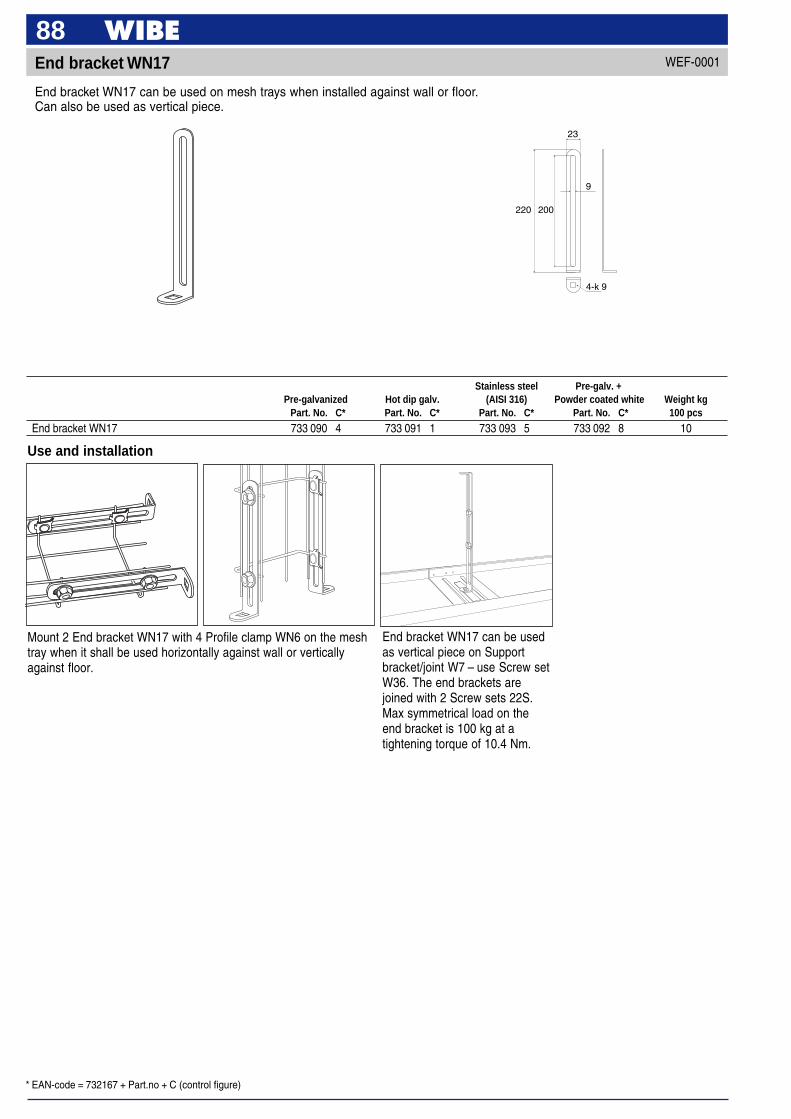
* EAN-code = 732167 + Part.no + C (control figure)
88End bracket WN17
Use and installation
Mount 2 End bracket WN17 with 4 Profile clamp WN6 on the meshtray when it shall be used horizontally against wall or verticallyagainst floor.
End bracket WN17 can be usedas vertical piece on Supportbracket/joint W7 – use Screw setW36. The end brackets arejoined with 2 Screw sets 22S.Max symmetrical load on theend bracket is 100 kg at atightening torque of 10.4 Nm.
Stainless steel Pre-galv. +Pre-galvanized Hot dip galv. (AISI 316) Powder coated white Weight kg
Part. No. C* Part. No. C* Part. No. C* Part. No. C* 100 pcs
End bracket WN17 733 090 4 733 091 1 733 093 5 733 092 8 10
End bracket WN17 can be used on mesh trays when installed against wall or floor.Can also be used as vertical piece.
WEF-0001
200
23
4-k 9
220
9
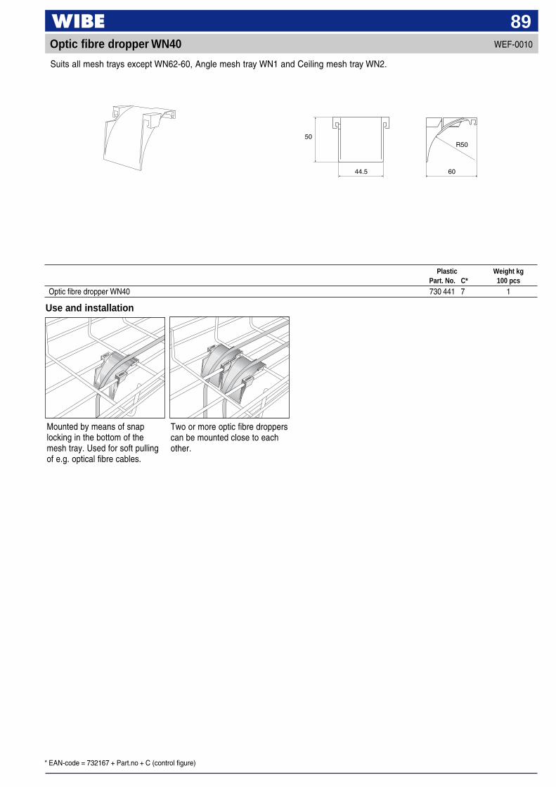
* EAN-code = 732167 + Part.no + C (control figure)
89WEF-0010Optic fibre dropper WN40
Suits all mesh trays except WN62-60, Angle mesh tray WN1 and Ceiling mesh tray WN2.
44.5 60
R5050
Use and installation
Mounted by means of snaplocking in the bottom of themesh tray. Used for soft pullingof e.g. optical fibre cables.
Two or more optic fibre dropperscan be mounted close to eachother.
Plastic Weight kgPart. No. C* 100 pcs
Optic fibre dropper WN40 730 441 7 1

* EAN-code = 732167 + Part.no + C (control figure)
90WEF-0001Junction box plate WN32
109
213
5.0 x 25 5.0 x 40 5.0 x 15 6
22.5
For mesh trays.
Use and installation
Easily mounted on the side ofthe mesh tray.
Can just as easily be mounted inthe bottom of the mesh tray.
Locking of the Junction boxplate WN32 is easily made withpliers.
The Junction box plate WN32can also be mounted with aninclination of 45° on the meshtray.
Stainless steel Pre-galv. +Pre-galvanized Hot dip galv. (AISI 316) Powder coated white Weight kg
Part. No. C* Part. No. C* Part. No. C* Part. No. C* 100 pcs
Junction box plate WN32 731 831 5 731 832 2 731 834 6 731 833 9 20
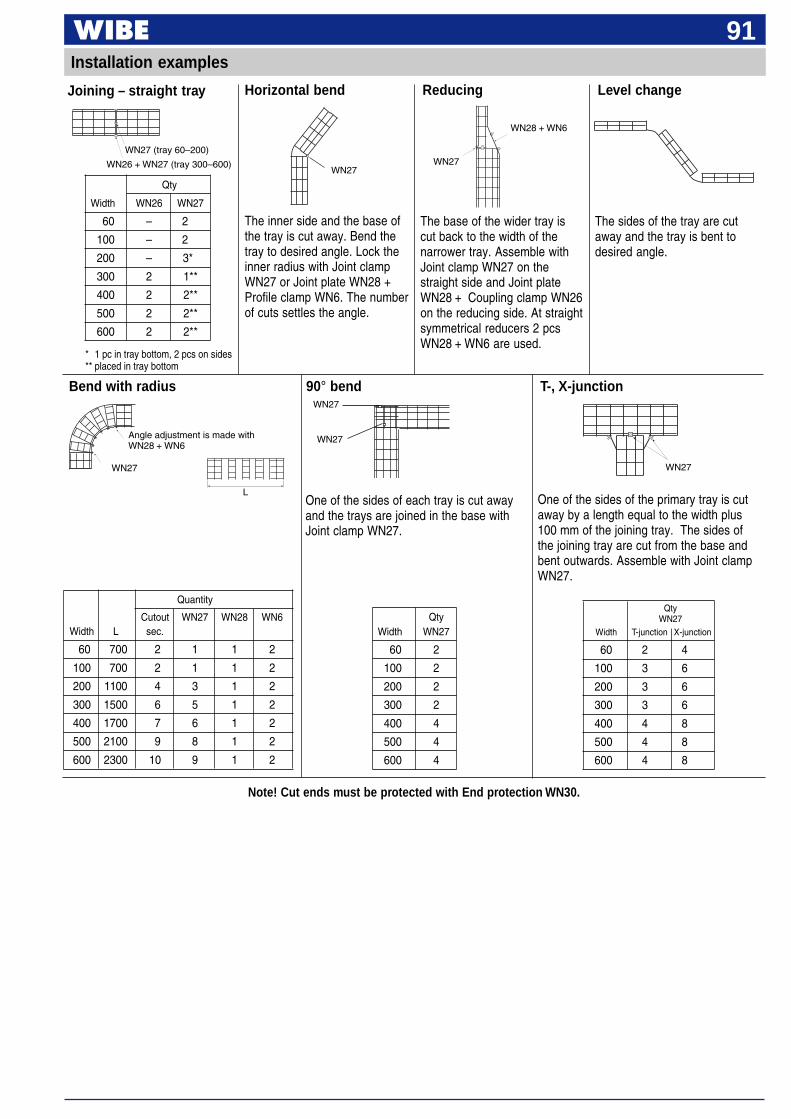
91Installation examples
Note! Cut ends must be protected with End protection WN30.
Joining – straight tray
WN27
The inner side and the base ofthe tray is cut away. Bend thetray to desired angle. Lock theinner radius with Joint clampWN27 or Joint plate WN28 +Profile clamp WN6. The numberof cuts settles the angle.
The base of the wider tray iscut back to the width of thenarrower tray. Assemble withJoint clamp WN27 on thestraight side and Joint plateWN28 + Coupling clamp WN26on the reducing side. At straightsymmetrical reducers 2 pcsWN28 + WN6 are used.
WN27
WN28 + WN6
ReducingHorizontal bend Level change
The sides of the tray are cutaway and the tray is bent todesired angle.
WN27 (tray 60–200)
Qty
Width WN26 WN27
60 – 2
100 – 2
200 – 3*
300 2 1**
400 2 2**
500 2 2**
600 2 2**
WN26 + WN27 (tray 300–600)
Bend with radius 90° bend T-, X-junction
One of the sides of each tray is cut awayand the trays are joined in the base withJoint clamp WN27.
One of the sides of the primary tray is cutaway by a length equal to the width plus100 mm of the joining tray. The sides ofthe joining tray are cut from the base andbent outwards. Assemble with Joint clampWN27.
* 1 pc in tray bottom, 2 pcs on sides** placed in tray bottom
Quantity
Cutout WN27 WN28 WN6Width L sec.
60 700 2 1 1 2
100 700 2 1 1 2
200 1100 4 3 1 2
300 1500 6 5 1 2
400 1700 7 6 1 2
500 2100 9 8 1 2
600 2300 10 9 1 2
QtyWidth WN27
60 2
100 2
200 2
300 2
400 4
500 4
600 4
L
Angle adjustment is made withWN28 + WN6
WN27 WN27
WN27
WN27
QtyWN27
Width T-junction X-junction
60 2 4
100 3 6
200 3 6
300 3 6
400 4 8
500 4 8
600 4 8
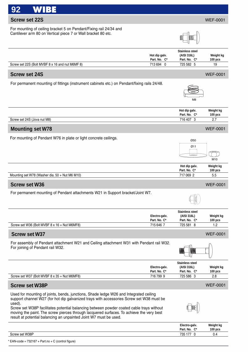
* EAN-code = 732167 + Part.no + C (control figure)
92
M8
Screw set 24S
For permanent mounting of fittings (instrument cabinets etc.) on Pendant/fixing rails 24/48.
For mounting of ceiling bracket 5 on Pendant/Fixing rail 24/34 andCantilever arm 80 on Vertical piece 7 or Wall bracket 80 etc.
Screw set 22S
Hot dip galv. Weight kgPart. No. C* 100 pcs
Screw set 24S (Jova nut M8) 716 407 3 2.7
Hot dip galv. Weight kgPart. No. C* 100 pcs
Mounting set W78 (Washer dia. 50 + Nut M6 M10) 717 069 2 5.5
Stainless steelHot dip galv. (AISI 316L) Weight kgPart. No. C* Part. No. C* 100 pcs
Screw set 22S (Bolt MVBF 8 x 16 and nut M6MF 8) 713 694 0 725 582 5 19
WEF-0001
WEF-0001
Ø50
Ø11
M10
Screw set W36For permanent mounting of Pendant attachments W21 in Support bracket/Joint W7.
Screw set W37
For assembly of Pendant attachment W21 and Ceiling attachment W31 with Pendant rail W32.For joining of Pendant rail W32.
Stainless steelElectro-galv. (AISI 316L) Weight kgPart. No. C* Part. No. C* 100 pcs
Screw set W36 (Bolt MVBF 8 x 16 + Nut M6MF8) 715 646 7 725 581 8 1.2
Stainless steelElectro-galv. (AISI 316L) Weight kgPart. No. C* Part. No. C* 100 pcs
Screw set W37 (Bolt MVBF 8 x 35 + Nut M6MF8) 716 799 9 725 586 3 2.8
WEF-0001
WEF-0001
Mounting set W78
For mounting of Pendant W76 in plate or light concrete ceilings.
WEF-0001
Screw set W38P
Used for mounting of joints, bends, junctions, Shade ledge W26 and Integrated ceilingsupport channel W27 (for hot dip galvanized trays with accessories Screw set W38 must beused).Screw set W38P facilitates potential balancing between powder coated cable trays withoutmoving the paint. The screw pierces through lacquered surfaces. To achieve the very bestresult at potential balancing an unpainted Joint W7 must be used.
Electro-galv. Weight kgPart. No. C* 100 pcs
Screw set W38P 735 177 0 0.4
WEF-0001

* EAN-code = 732167 + Part.no + C (control figure)
93
Screw W40
For locking of T-joint W29 in open junctions.
Locking plug W41
For quick locking of joints, bends and branches in cable trays and lighting trunking.
Electro-galv. Weight kgPart. No. C* 100 pcs
Screw W40 (Screw RXS ST 5.5 x 13-H) 721 868 4 0.3
Plastic Weight kgPart. No. C* 100 pcs
Locking plug W41 718 645 7 0.1
WEF-0001
WEF-0001
Screw set W38
For mounting of hot dip galvanized Cable trays W3 and Installation trays W4with accessories.
Electro-galv. Dacromet Weight kgPart. No. C* Part. No. C* 100 pcs
Screw set W38 716 907 733 258 8 0.4
WEF-0001
Screw set W34
For mounting Tray W3 on Cantilever arm 50.For mounting Locking Hook W77 onto Pendant rail W32.For mounting Angle bracket W8 onto Pendant rail W32.For mounting Junction box plate W24 in Tray W3, Lighting trunking W70 and W71.For mounting Angle Bracket W8 in Tray W3, Lighting trunking W70 and W71.For assembly of Angle bracket W8 (light fitting bracket).For mounting of Wall bracket WN20.For joining Trays W4.For Wall bracket W-swing 2.
Stainless steelDacromet Electro-galv. (AISI 316L) Weight kg
Part. No. C* Part. No. C* Part. No. C* 100 pcs
Screw set W34 (Bolt MSCS 6 x 12 + Nut M6MF6) 734 646 2 718 473 6 725 589 4 0.8
WEF-0001
Screw set 70S
2 Cantilever arm 70 can be mounted with Screw set 70S to forma vertical piece, see page 25.
Stainless steelHot dip galv. (AISI 316L) Weight kgPart. No. C* Part. No. C* 100 pcs
Screw set 72S (Bolt MVBF 10 x 60 and nut M6M 10) 728 570 9 728 571 6 5.0
For installation of several Cantilever arms 70 to form pendants, see page 25.
Screw set 72S
Stainless steelHot dip galv. (AISI 316L) Weight kgPart. No. C* Part. No. C* 100 pcs
Screw set 70S (Bolt M6S 10 x 20 and nut M6M 10) 728 568 6 728 569 3 3.4
WEF-0001
WEF-0001
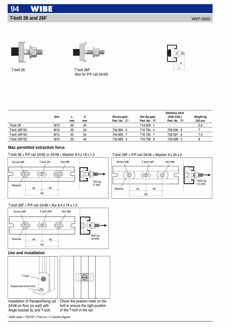
* EAN-code = 732167 + Part.no + C (control figure)
94T-bolt 26 and 26F WEF-0002
Use and installation
Max permitted extraction force
T-bolt 26 + P/F-rail 24/40 or 24/48 + Washer 8.4 x 19 x 1.5
T-bolt 26Screw M8
Washer
Nut M8
45 45
90
T-bolt 26F + P/F-rail 24/48 + Washer 9 x 35 x 2
T-bolt 26F + P/F-rail 24/48 + Nut 8.4 x 19 x 1.5
700 kg(7 kN)
45
T-bolt 26FScrew M8
Washer
Nut M8
45
90
800 kg(8 KN)
45
T-bolt 26FScrew M8
Washer
Nut M8
45
90
1300 kg(13 kN)
Installation of Pendant/fixing rail24/48 on floor (or wall) withAngle bracket 5L and T-bolt.
T-bolt
Expansion-shell bolt
Check the position mark on thebolt to ensure the right positionof the T-bolt in the rail.
L
A
T-bolt 26 T-bolt 26F(Not for P/F-rail 24/40)
Stainless steelDim L A Electro-galv. Hot dip galv. (AISI 316L) Weight kg
mm mm Part. No. C* Part. No. C* Part. No. C* 100 pcs
T-bolt 26 M10 30 24 714 009 1 5.0T-bolt 26F/30 M10 30 24 734 864 0 716 794 4 728 596 9 7T-bolt 26F/40 M10 40 34 734 865 7 716 795 1 728 597 6 7.5T-bolt 26F/50 M10 50 44 734 866 4 716 796 8 728 598 3 8
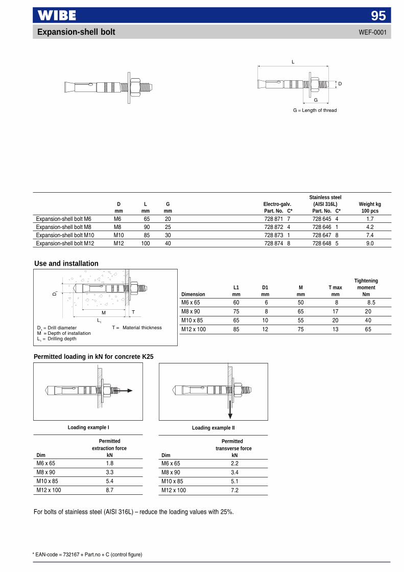
* EAN-code = 732167 + Part.no + C (control figure)
95Expansion-shell bolt WEF-0001
Permitted loading in kN for concrete K25
Use and installation
TighteningL1 D1 M T max moment
Dimension mm mm mm mm Nm
M6 x 65 60 6 50 8 8.5
M8 x 90 75 8 65 17 20
M10 x 85 65 10 55 20 40
M12 x 100 85 12 75 13 65
D1
L1
TM
D1
= Drill diameterM = Depth of installationL
1= Drilling depth
Loading example I Loading example II
Permittedtransverse force
Dim kN
M6 x 65 2.2
M8 x 90 3.4
M10 x 85 5.1
M12 x 100 7.2
For bolts of stainless steel (AISI 316L) – reduce the loading values with 25%.
Permittedextraction force
Dim kN
M6 x 65 1.8
M8 x 90 3.3
M10 x 85 5.4
M12 x 100 8.7
Stainless steelD L G Electro-galv. (AISI 316L) Weight kg
mm mm mm Part. No. C* Part. No. C* 100 pcs
Expansion-shell bolt M6 M6 65 20 728 871 7 728 645 4 1.7Expansion-shell bolt M8 M8 90 25 728 872 4 728 646 1 4.2Expansion-shell bolt M10 M10 85 30 728 873 1 728 647 8 7.4Expansion-shell bolt M12 M12 100 40 728 874 8 728 648 5 9.0
T = Material thickness
L
D
G = Length of thread
G
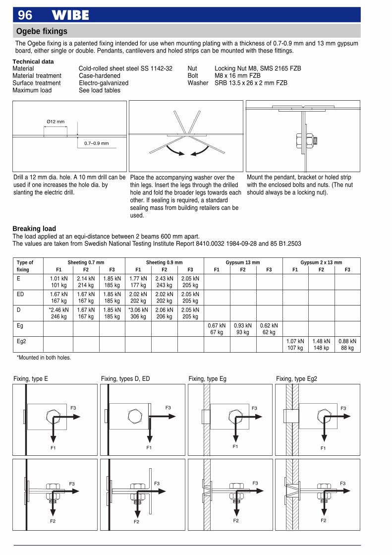
96Ogebe fixingsThe Ogebe fixing is a patented fixing intended for use when mounting plating with a thickness of 0.7-0.9 mm and 13 mm gypsumboard, either single or double. Pendants, cantilevers and holed strips can be mounted with these fittings.
Drill a 12 mm dia. hole. A 10 mm drill can beused if one increases the hole dia. byslanting the electric drill.
Place the accompanying washer over thethin legs. Insert the legs through the drilledhole and fold the broader legs towards eachother. If sealing is required, a standardsealing mass from building retailers can beused.
Mount the pendant, bracket or holed stripwith the enclosed bolts and nuts. (The nutshould always be a locking nut).
Ø12 mm
0.7–0.9 mm
Technical dataMaterial Cold-rolled sheet steel SS 1142-32Material treatment Case-hardenedSurface treatment Electro-galvanizedMaximum load See load tables
Breaking loadThe load applied at an equi-distance between 2 beams 600 mm apart.The values are taken from Swedish National Testing Institute Report 8410.0032 1984-09-28 and 85 B1.2503
Type of Sheeting 0.7 mm Sheeting 0.9 mm Gypsum 13 mm Gypsum 2 x 13 mmfixing F1 F2 F3 F1 F2 F3 F1 F2 F3 F1 F2 F3
E 1.01 kN 2.14 kN 1.85 kN 1.77 kN 2.43 kN 2.05 kN101 kg 214 kg 185 kg 177 kg 243 kg 205 kg
ED 1.67 kN 1.67 kN 1.85 kN 2.02 kN 2.02 kN 2.05 kN167 kg 167 kg 185 kg 202 kg 202 kg 205 kg
D *2.46 kN 1.67 kN 1.85 kN *3.06 kN 2.06 kN 2.05 kN246 kg 167 kg 185 kg 306 kg 206 kg 205 kg
Eg 0.67 kN 0.93 kN 0.62 kN67 kg 93 kg 62 kg
Eg2 1.07 kN 1.48 kN 0.88 kN107 kg 148 kp 88 kg
*Mounted in both holes.
Fixing, type E Fixing, types D, ED Fixing, type Eg Fixing, type Eg2
F3
F1
F3
F1
F3
F1
F3
F1
F3
F2
F3
F2
F3
F2
F3
F2
Nut Locking Nut M8, SMS 2165 FZBBolt M8 x 16 mm FZBWasher SRB 13.5 x 26 x 2 mm FZB
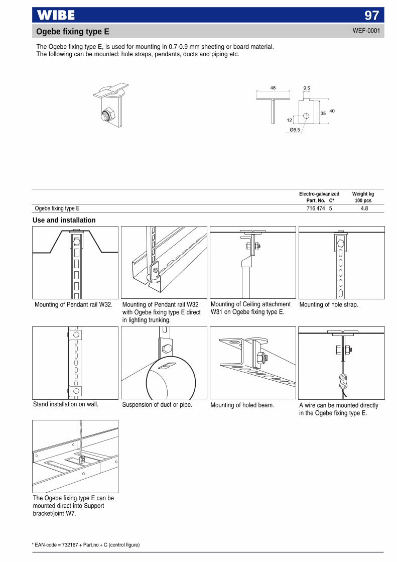
* EAN-code = 732167 + Part.no + C (control figure)
97Ogebe fixing type E
The Ogebe fixing type E, is used for mounting in 0.7-0.9 mm sheeting or board material.The following can be mounted: hole straps, pendants, ducts and piping etc.
WEF-0001
Use and installation
Mounting of Pendant rail W32with Ogebe fixing type E directin lighting trunking.
Mounting of Pendant rail W32. Mounting of Ceiling attachmentW31 on Ogebe fixing type E.
Mounting of hole strap.
Suspension of duct or pipe.Stand installation on wall. Mounting of holed beam. A wire can be mounted directlyin the Ogebe fixing type E.
Electro-galvanized Weight kgPart. No. C* 100 pcs
Ogebe fixing type E 716 474 5 4.8
The Ogebe fixing type E can bemounted direct into Supportbracket/joint W7.
48
35 40
12
9.5
Ø8.5
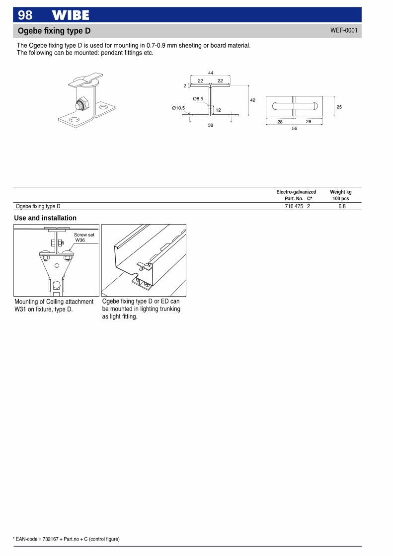
* EAN-code = 732167 + Part.no + C (control figure)
98Ogebe fixing type D
The Ogebe fixing type D is used for mounting in 0.7-0.9 mm sheeting or board material.The following can be mounted: pendant fittings etc.
22
44
222
Ø8.5
Ø10.5 12
38
42
28 28
56
25
WEF-0001
Use and installation
Screw set W36
Mounting of Ceiling attachmentW31 on fixture, type D.
Electro-galvanized Weight kgPart. No. C* 100 pcs
Ogebe fixing type D 716 475 2 6.8
Ogebe fixing type D or ED canbe mounted in lighting trunkingas light fitting.
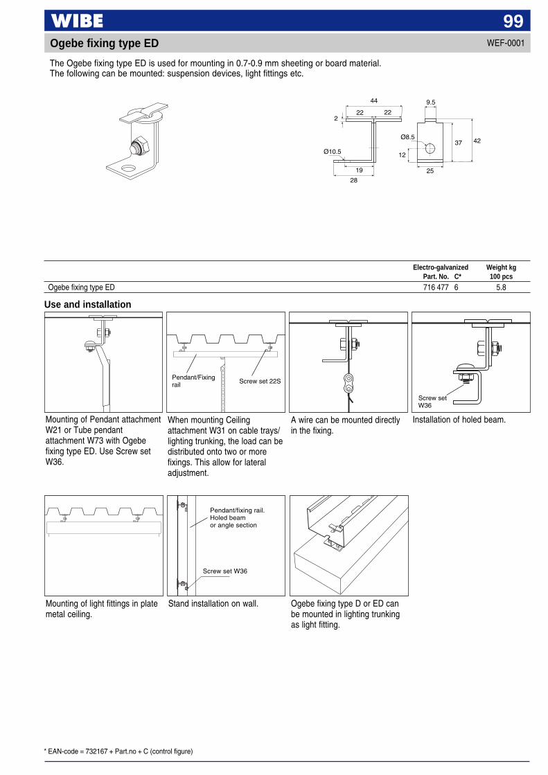
* EAN-code = 732167 + Part.no + C (control figure)
99Ogebe fixing type ED
The Ogebe fixing type ED is used for mounting in 0.7-0.9 mm sheeting or board material.The following can be mounted: suspension devices, light fittings etc.
Use and installation
Pendant/Fixingrail Screw set 22S
Screw setW36
Mounting of Pendant attachmentW21 or Tube pendantattachment W73 with Ogebefixing type ED. Use Screw setW36.
When mounting Ceilingattachment W31 on cable trays/lighting trunking, the load can bedistributed onto two or morefixings. This allow for lateraladjustment.
Installation of holed beam.
Electro-galvanized Weight kgPart. No. C* 100 pcs
Ogebe fixing type ED 716 477 6 5.8
44
19
12
222
Ø10.5
Ø8.5
9.5
22
28
37 42
25
A wire can be mounted directlyin the fixing.
WEF-0001
Mounting of light fittings in platemetal ceiling.
Pendant/fixing rail.Holed beamor angle section
Screw set W36
Stand installation on wall. Ogebe fixing type D or ED canbe mounted in lighting trunkingas light fitting.
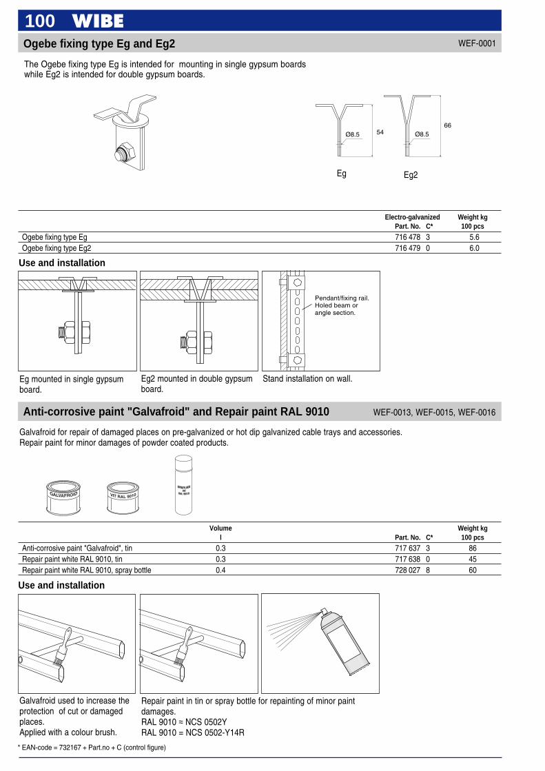
* EAN-code = 732167 + Part.no + C (control figure)
100Ogebe fixing type Eg and Eg2
The Ogebe fixing type Eg is intended for mounting in single gypsum boardswhile Eg2 is intended for double gypsum boards.
WEF-0001
Electro-galvanized Weight kgPart. No. C* 100 pcs
Ogebe fixing type Eg 716 478 3 5.6Ogebe fixing type Eg2 716 479 0 6.0
Use and installation
Pendant/fixing rail.Holed beam orangle section.
Eg mounted in single gypsumboard.
Eg2 mounted in double gypsumboard.
Stand installation on wall.
Ø8.5 Ø8.566
54
Eg Eg2
Anti-corrosive paint "Galvafroid" and Repair paint RAL 9010
Galvafroid for repair of damaged places on pre-galvanized or hot dip galvanized cable trays and accessories.Repair paint for minor damages of powder coated products.
WEF-0013, WEF-0015, WEF-0016
Galvafroid used to increase theprotection of cut or damagedplaces.Applied with a colour brush.
Repair paint in tin or spray bottle for repainting of minor paintdamages.RAL 9010 ≈ NCS 0502YRAL 9010 = NCS 0502-Y14R
Use and installation
Volume Weight kgl Part. No. C* 100 pcs
Anti-corrosive paint "Galvafroid", tin 0.3 717 637 3 86Repair paint white RAL 9010, tin 0.3 717 638 0 45Repair paint white RAL 9010, spray bottle 0.4 728 027 8 60
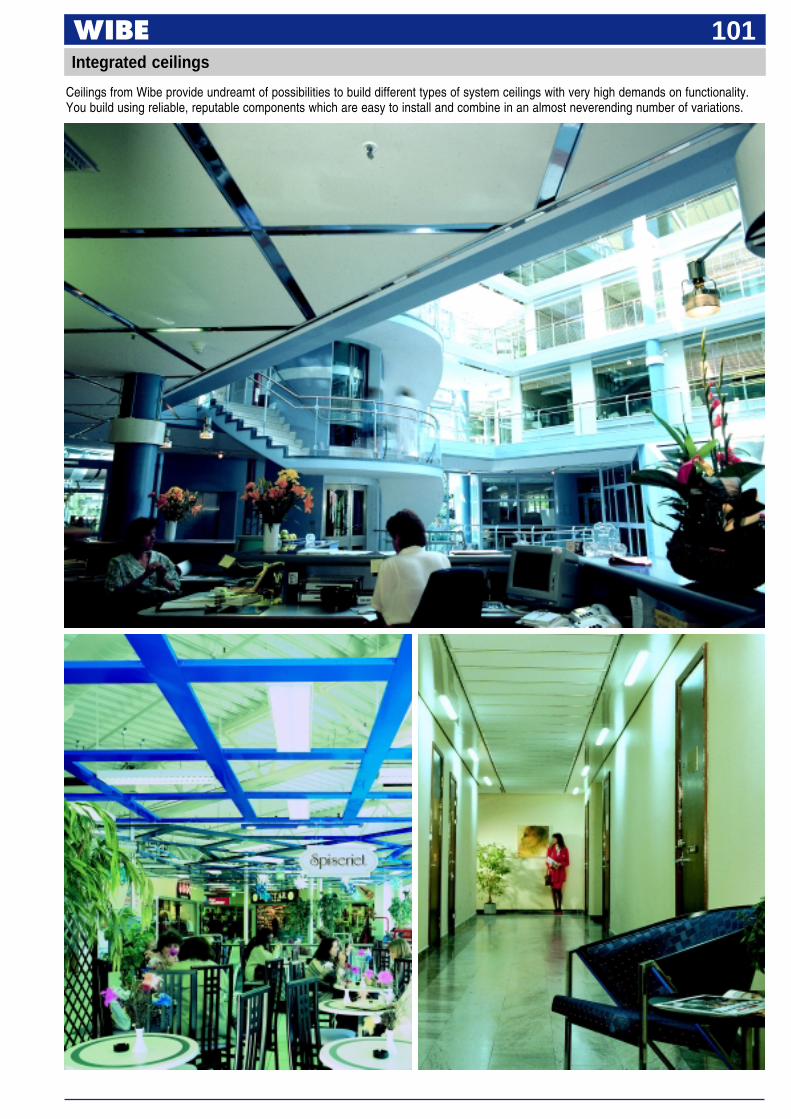
101
Ceilings from Wibe provide undreamt of possibilities to build different types of system ceilings with very high demands on functionality.You build using reliable, reputable components which are easy to install and combine in an almost neverending number of variations.
Integrated ceilings

102Integrated ceilings
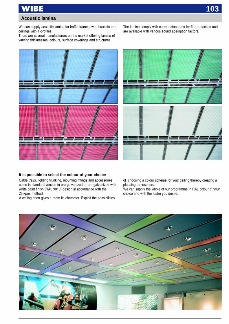
103Acoustic lamina
We can supply acoustic lamina for baffle frames, wire baskets andceilings with T-profiles.There are several manufacturers on the market offering lamina ofvarying thicknesses, colours, surface coverings and structures.
The lamina comply with current standards for fire-protection andare available with various sound absorption factors.
It is possible to select the colour of your choiceCable trays, lighting trunking, mounting fittings and accessoriescome in standard version in pre-galvanized or pre-galvanized withwhite paint finish (RAL 9010) design in accordance with theZinkpox method.A ceiling often gives a room its character. Exploit the possibilities
of choosing a colour scheme for your ceiling thereby creating apleasing atmosphere.We can supply the whole of our programme in RAL colour of yourchoice and with the lustre you desire.
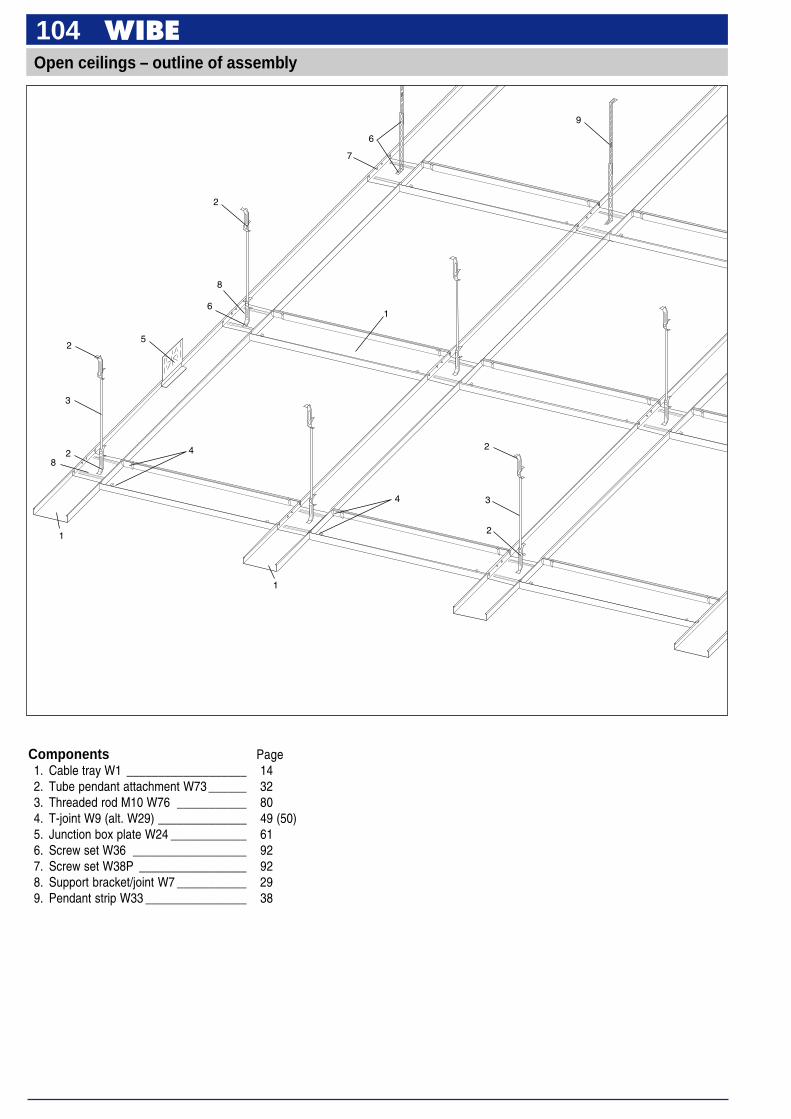
104Open ceilings – outline of assembly
Components Page1. Cable tray W1 ___________________ 142. Tube pendant attachment W73 ______ 323. Threaded rod M10 W76 ___________ 804. T-joint W9 (alt. W29) ______________ 49 (50)5. Junction box plate W24 ____________ 616. Screw set W36 __________________ 927. Screw set W38P _________________ 928. Support bracket/joint W7 ___________ 299. Pendant strip W33 ________________ 38
2
2
3
2
4
1
4
1
5
1
2
3
2
6
8
6
9
7
8
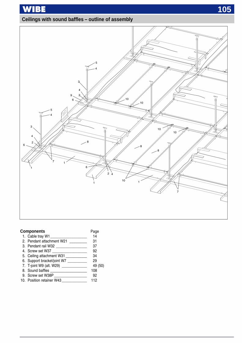
105
4
5
5
4
3
4
2
6
3
4
26
1
7 1
8
8
6
1
2 4
8
7
9
10
1010
1010
1
Ceilings with sound baffles – outline of assembly
Components Page1. Cable tray W1___________________ 142. Pendant attachment W21 _________ 313. Pendant rail W32 ________________ 374. Screw set W37 __________________ 925. Ceiling attachment W31 ___________ 346. Support bracket/joint W7 __________ 297. T-joint W9 (alt. W29) _____________ 49 (50)8. Sound baffles ___________________ 1089. Screw set W38P _________________ 92
10. Position retainer W43 _____________ 112
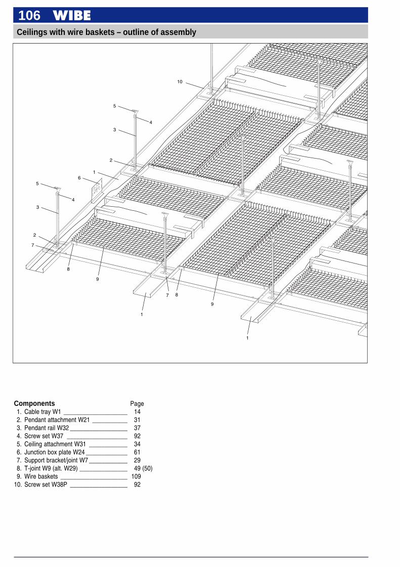
106Ceilings with wire baskets – outline of assembly
4
4
5
3
2
16
3
5
7
8
9
1
7 8
9
1
10
2
Components Page1. Cable tray W1 ____________________ 142. Pendant attachment W21 ___________ 313. Pendant rail W32 __________________ 374. Screw set W37 ___________________ 925. Ceiling attachment W31 ____________ 346. Junction box plate W24 _____________ 617. Support bracket/joint W7 ____________ 298. T-joint W9 (alt. W29) _______________ 49 (50)9. Wire baskets _____________________ 109
10. Screw set W38P __________________ 92
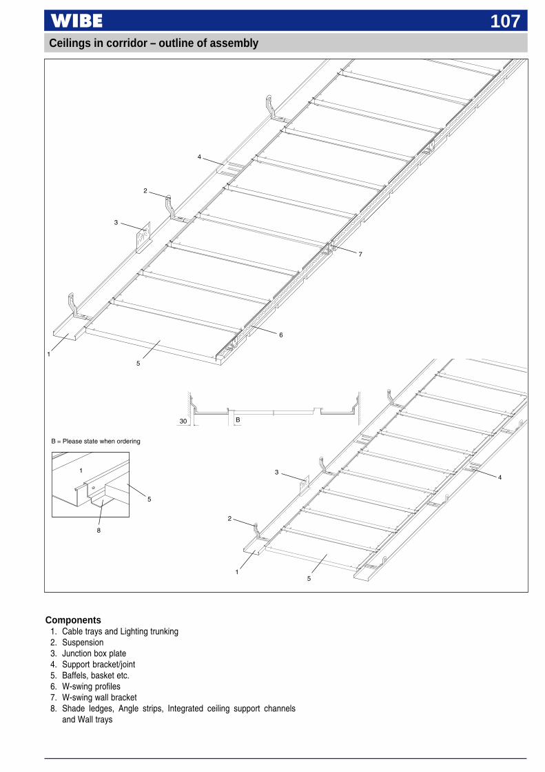
107
Components1. Cable trays and Lighting trunking2. Suspension3. Junction box plate4. Support bracket/joint5. Baffels, basket etc.6. W-swing profiles7. W-swing wall bracket8. Shade ledges, Angle strips, Integrated ceiling support channels
and Wall trays
Ceilings in corridor – outline of assembly
4
2
3
7
6
51
1
2
5
34
B30
8
1
5
B = Please state when ordering
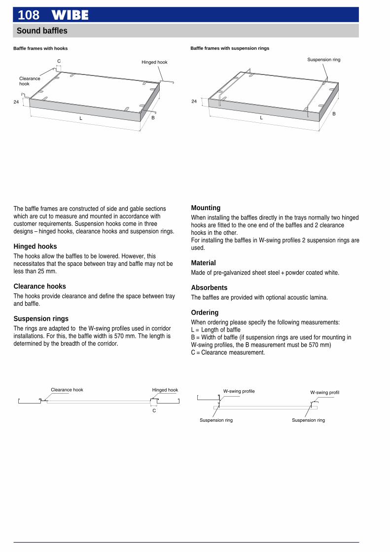
108
The baffle frames are constructed of side and gable sectionswhich are cut to measure and mounted in accordance withcustomer requirements. Suspension hooks come in threedesigns – hinged hooks, clearance hooks and suspension rings.
Hinged hooksThe hooks allow the baffles to be lowered. However, thisnecessitates that the space between tray and baffle may not beless than 25 mm.
Clearance hooksThe hooks provide clearance and define the space between trayand baffle.
Suspension ringsThe rings are adapted to the W-swing profiles used in corridorinstallations. For this, the baffle width is 570 mm. The length isdetermined by the breadth of the corridor.
Sound baffles
MountingWhen installing the baffles directly in the trays normally two hingedhooks are fitted to the one end of the baffles and 2 clearancehooks in the other.For installing the baffles in W-swing profiles 2 suspension rings areused.
MaterialMade of pre-galvanized sheet steel + powder coated white.
AbsorbentsThe baffles are provided with optional acoustic lamina.
OrderingWhen ordering please specify the following measurements:L = Length of baffleB = Width of baffle (if suspension rings are used for mounting inW-swing profiles, the B measurement must be 570 mm)C = Clearance measurement.
Clearance hook Hinged hook
C
W-swing profilW-swing profile
L
24
C
B
Hinged hook
Clearancehook
Baffle frames with hooks
L
24
B
Suspension ring
Baffle frames with suspension rings
Suspension ring Suspension ring
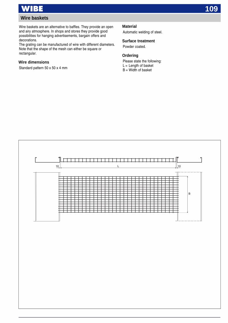
109
Wire baskets are an alternative to baffles. They provide an openand airy atmosphere. In shops and stores they provide goodpossibilities for hanging advertisements, bargain offers anddecorations.The grating can be manufactured of wire with different diameters.Note that the shape of the mesh can either be square orrectangular.
Wire dimensionsStandard pattern 50 x 50 x 4 mm
MaterialAutomatic welding of steel.
Surface treatmentPowder coated.
OrderingPlease state the following:L = Length of basketB = Width of basket
Wire baskets
L
B
10 10
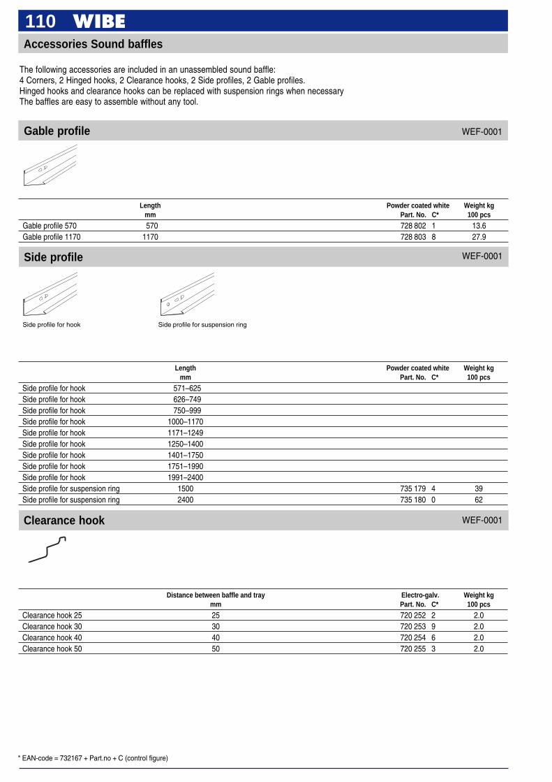
* EAN-code = 732167 + Part.no + C (control figure)
110
Gable profile
Side profile
Clearance hook
Accessories Sound baffles
The following accessories are included in an unassembled sound baffle:4 Corners, 2 Hinged hooks, 2 Clearance hooks, 2 Side profiles, 2 Gable profiles.Hinged hooks and clearance hooks can be replaced with suspension rings when necessaryThe baffles are easy to assemble without any tool.
Side profile for hook Side profile for suspension ring
Length Powder coated white Weight kgmm Part. No. C* 100 pcs
Gable profile 570 570 728 802 1 13.6Gable profile 1170 1170 728 803 8 27.9
WEF-0001
WEF-0001
WEF-0001
Length Powder coated white Weight kgmm Part. No. C* 100 pcs
Side profile for hook 571–625Side profile for hook 626–749Side profile for hook 750–999Side profile for hook 1000–1170Side profile for hook 1171–1249Side profile for hook 1250–1400Side profile for hook 1401–1750Side profile for hook 1751–1990Side profile for hook 1991–2400Side profile for suspension ring 1500 735 179 4 39Side profile for suspension ring 2400 735 180 0 62
Distance between baffle and tray Electro-galv. Weight kgmm Part. No. C* 100 pcs
Clearance hook 25 25 720 252 2 2.0Clearance hook 30 30 720 253 9 2.0Clearance hook 40 40 720 254 6 2.0Clearance hook 50 50 720 255 3 2.0
* EAN-code = 732167 + Part.no + C (control figure)
111
Suspension ring
Reinforced profile
Corner
Hinged hook
Pre-galvanized Weight kgPart. No. C* 100 pcs
Corner 728 859 5 2.5
WEF-0001
WEF-0001
WEF-0001
WEF-0001
Distance between baffle and tray Electro-galv. Weight kgmm Part. No. C* 100 pcs
Hinged hook 25–30 25–30 720 260 7 2.0Hinged hook 40 40 720 261 4 2.0Hinged hook 50 50 720 262 1 2.0
Length Electro-galv. Weight kgmm Part. No. C* 100 pcs
Suspension ring 575 575 728 804 5 7Suspension ring 1175 1175 728 805 2 14
Length Powder coated white Weight kgmm Part. No. C* 100 pcs
Reinforced profile 570 570 733 995 2 13.6Reinforced profile 1170 1170 733 996 9 27.9
* EAN-code = 732167 + Part.no + C (control figure)
112Position retainer W43 and Support W42
Support W42Mounted in T-joint W9 as asupport for cables.
Position retainer W43Two pcs are mounted per baffle.
To be mounted in the cable trays or lighting trunking to hold sound baffles in required position.
Position retainer W43 holds thesound baffles in the correctposition. W43 is snapped tightinto the edge of the cable tray orlighting trunking.
Use and installation
White plastic Weight kgPart. No. C* 100 pcs
Position retainer W43 718 245 9 0.4Support W42 718 214 5 0.4
Support W42 is mounted onT-joint W9 to prevent the cablesfrom gliding out over the cornerof the cable tray or lightingtrunking. W42 is snapped tightinto the edge of the tray.
WEF-0017
Gypsum clip
15.3
10
Used to mount gypsum wallboards in baffle frames.For Profile W-swing 1–5.
Steel strip Weight kgPart. No. C* 100 pcs
Gypsum clip 732 241 1 0.4
Use and installation
WEF-0001
Gypsum boards in Wibe´s baffleframes must have dimensionsthat are 20 mm smaller than thesize of the baffle (L - 20, B - 20).The clip will keep the board inplace.
Normally it is enough with 4gypsum clips pro baffle.The clips must be mounteddiagonally.
Lock the gypsum clip bypressing down the tab.The gypsum clip suits a 9 mmthick board.

* EAN-code = 732167 + Part.no + C (control figure)
113
Enables clip mounting in baffle frame.
Use and installation
Frame clip W90
Mounting of light fittings onAngle strip W46 with Frameclips W90.
Installation of air component.The Frame clip W90 is clampedtight under the edge of thesection.
Mounting of decoration strip etc.
Light fitting mounted in baffleframe. 2 T-profiles mounted with4 Frame clips W90.
In large frames an extra supportfor the absorbent lamina can berequired. Install a T-section with2 Frame clips W90.
T-section is easily mounted withFrame clips W90 in the baffleframes.
Pre-galvanized Weight kgPart. No. C* 100 pcs
Frame clip W90 (screw RXS Combi B6 x 19 fzb) 723 021 1 1.0
WEF-0001
24
25

114W-swing – Ceilings in corridor
Suspension system – see page 12.
Cable tray W1page 14
Profile W-swing 2page 115
Wall bracket W-swing 2page 117
Suspension system – see page 12.
Cable tray W1page 14
Profile W-swing 1page 115
Sound baffelpage 108
Profile W-swing 5page 117
Profile W-swing 3page 116
Sound baffelpage 108
Profile W-swing 4page 116

* EAN-code = 732167 + Part.no + C (control figure)
115Profile W-swing 1
600 mm c/c is standard. Other c/c measurements can be manufactured on request.
Profile W-swing 2600 mm c/c is standard. Other c/c measurements can be manufactured on request.
Use and installation
Use and installation
L = 2.4 m
55
300
c/c 60030
Installation with tray on both sides and Profile W-swing 1 hangingon tray edge. Hanging baffle, folding in both directions.
Corridor width = max. 2 metres Premises with check pattern system
Installation with tray and Profile W-swing 1. Hanging baffles, foldingin both directions. The trays have pendular suspension fromceiling.
30c/c 600
L = 2.4 m
50
7 x 40
300
Installation with Profile W-swing 2 on Wall bracket W-swing 2.Hanging baffle, folding in both directions.
Ceiling installation with Profile W-swing 2. Hanging baffle, folding inboth directions.
Powder coated white Weight kgPart. No. C* 100 pcs
Profile W-swing 1 721 708 3 210
Pre-galv. +Pre-galvanized Powder coated white Weight kg
Part. No. C* Part. No. C* 100 pcs
Profile W-swing 2 728 866 3 721 709 0 110
Corridor width = max. 2 metres
WEF-0001
WEF-0001
* EAN-code = 732167 + Part.no + C (control figure)
116Profile W-swing 3
600 mm c/c is standard. Other c/c measurements can be manufactured on request.
Installation with tray and Profile W-swing 1, Wall bracket W-swing 2 and Profile W-swing 2 with pendant and Profile W-swing 3.Hanging baffles, folding in both directions.
Profile W-swing 4600 mm c/c is standard. Other c/c measurements can be manufactured on request.
L = 2.4 m
7 x 40
50
30
300
c/c 600
L = 2.4 m 50
c/c 600
300
30
7 x 40
Use and installation
Use and installation
Installation with tray and Profile W-swing 1, Profile W-swing 4 on pendant and wall ledge.Hanging baffle, folding in both directions. Fixed ceiling lamina between Profile W-swing 4 and Wall ledge W46.
Powder coated white Weight kgPart. No. C* 100 pcs
Profile W-swing 3 721 710 6 277
Corridor
Powder coated white Weight kgPart. No. C* 100 pcs
Profile W-swing 4 721 711 3 370
Corridor
WEF-0001
WEF-0001
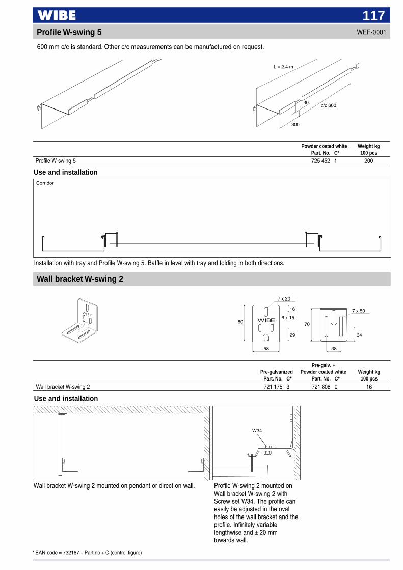
* EAN-code = 732167 + Part.no + C (control figure)
117Profile W-swing 5
600 mm c/c is standard. Other c/c measurements can be manufactured on request.
L = 2.4 m
c/c 60030
300
Use and installation
Installation with tray and Profile W-swing 5. Baffle in level with tray and folding in both directions.
Powder coated white Weight kgPart. No. C* 100 pcs
Profile W-swing 5 725 452 1 200
WEF-0001
Use and installation
Wall bracket W-swing 2
Wall bracket W-swing 2 mounted on pendant or direct on wall. Profile W-swing 2 mounted onWall bracket W-swing 2 withScrew set W34. The profile caneasily be adjusted in the ovalholes of the wall bracket and theprofile. Infinitely variablelengthwise and ± 20 mmtowards wall.
Pre-galv. +Pre-galvanized Powder coated white Weight kg
Part. No. C* Part. No. C* 100 pcs
Wall bracket W-swing 2 721 175 3 721 808 0 16
Corridor
WIBE
7 x 20
16
6 x 15
29
70
58 38
80
34
7 x 50
W34
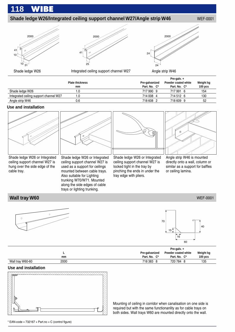
* EAN-code = 732167 + Part.no + C (control figure)
118Shade ledge W26/Integrated ceiling support channel W27/Angle strip W46
Shade ledge W26
4141
Angle strip W46
2410
Angle strip W46 is mounteddirectly onto a wall, column orsimilar as a support for bafflesor ceiling lamina.
Shade ledge W26 or Integratedceiling support channel W27 ishung over the side edge of thecable tray.
Shade ledge W26 or Integratedceiling support channel W27 isused as a support for ceilingsmounted between cable trays.Also suitable for Lightingtrunking W70/W71. Mountedalong the side edges of cabletrays or lighting trunking.
20002000 2000
31 25 24
WEF-0001
Integrated ceiling support channel W27
10
Pre-galv. +Plate thickness Pre-galvanized Powder coated white Weight kg
mm Part. No. C* Part. No. C* 100 pcs
Shade ledge W26 1.0 717 990 9 717 991 6 154Integrated ceiling support channel W27 1.0 714 008 4 714 512 6 130Angle strip W46 0.6 718 608 2 718 609 9 52
Use and installation
Shade ledge W26 or Integratedceiling support channel W27 islocked tight in the tray bypinching the ends in under thetray edge with pliers.
Wall tray W60
Pre-galv. +L Pre-galvanized Powder coated white Weight kg
mm Part. No. C* Part. No. C* 100 pcs
Wall tray W60-60 2000 718 383 8 720 784 8 135
Use and installation
Mounting of ceiling in corridor when canalisation on one side isrequired but with the same functionanlity as for cable trays onboth sides. Wall trays W60 are mounted directly onto the wall.
WEF-0001
40
70
15
16
60

119
Use Vertical piece 2F atinstallations in corridors withgypsum walls. The installationcan easily be adjusted bothvertically and horizontally andwill not be effected of vibrationsin the walls.
Example of corridor installation. This way of mounting reduce theobliquity of the cable tray.
Example of installation with uneven loadings. The installation hasbeen reinforced with lashing wires. The wire can be fixed to theceiling or the ceiling bracket.
Installation of Profile W-swing 2 and wall bracket, on the samevertical pieces as the cable ladders/trays. Hanging baffle, folding inboth directions.
Installation examples