cable trusses - university of colorado...
TRANSCRIPT
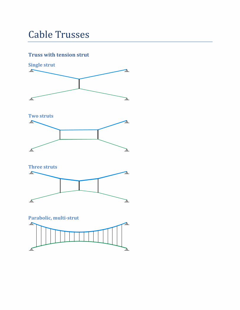
Cable Trusses
Truss with tension strut
Single strut
Two struts
Three struts
Parabolic, multi-strut

Truss with compression strut
Single strut
Two struts
Three struts
Parabolic, multi-strut

One Strut, Asymmetric
Nested Trusses

Deflection Control
Example – Unstiffened cable with single point load A cable carries a 50k concentrated transient load at the middle of a 200 ft span. We first consider behavior of an unstiffened cable and get deflection under transient load. We want to keep transient load to span/180 or less; that’s 1.11 ft. Sag under transient load is 20 ft.
Unstiffened cable
To get started, we have to select a strand. We use geometry for the cable under total load to estimate Tu, and pick a strand. Then we are ready to make a model & perform better computations of forces.
Figure 1
Symbolic relations
Hf=PL/4
T=1.02 H
Numerical values
H =125k
Tu=140tn
Select 1-1/2” strand.
Model and reference state Set up a model. Our reference state is self weight plus transient load. The model file is Truss01.csXml Try to balance the reference state. You’ll need to adjust z- coordinates of nodes and adjust the value of H. Table 1 Node Coordinates for Balance Under Transient Load, H = 126.2k,
ID X ft Y ft Z ft Sx Sy Sz
Left 0 0 0 True True True
a 0 20 -4.03049146
b 0 40 -8.04573719
c 0 60 -12.04573719
d 0 80 -16.03049146
Mid 0 100 -20
e 0 120 -16.03049146
f 0 140 -12.04573719
g 0 160 -8.04573719
h 0 180 -4.03049146
Right 0 200 0 True True True

Analysis for transient load absent What is the geometry of the cable when the transient load P is absent? We find out by using a force displacement analysis. We obtain the following for deflection from the reference state. Table 2
ID Dx ft Dy ft Dz ft
Left 0 0 0
a 0 -0.44 -1.48
b 0 -0.59 -1.81
c 0 -0.52 -0.95
d 0 -0.3 1.12
Mid 0 0 4.33
e 0 0.3 1.12
f 0 0.52 -0.95
g 0 0.59 -1.81
h 0 0.44 -1.48
Right 0 0 0
Deflections are upward when we remove the transient load. Deflections are too big. Some of this is the change in shape of the cable from line segments when the transient load is present to parabolic when transient load is absent. To see this, add deflections Dx, Dy, Dz to node coordinate in the reference state. You’ll get the values shown in Table 3. We also list, for comparison, a set of z-coordinates on a true parabola. The coordinates of our cable differ slightly from a true parabola by the unequal self weight at nodes. Still all z-coordinates are with 0.11’ of a parabola. Table 3
ID X ft Y ft Z ft Z - parabola
Left 0 0 0 0
a 0 19.56 -5.51 -5.53
b 0 39.41 -9.86 -9.92
c 0 59.48 -13.00 -13.10
d 0 79.70 -14.91 -15.02
Mid 0 100.00 -15.67 -15.67
e 0 120.30 -14.91 -15.02
f 0 140.52 -13.00 -13.10
g 0 160.59 -9.86 -9.92
h 0 180.44 -5.51 -5.53
Right 0 200.00 0.00 0.00

Influence of stretch in cable Some of the deflection is from stretch of the cable. Let’s check on this. We start with the transient load present, set up a balanced reference state, then use a force-displacement analysis for zero load; not even self weight is present. Here are the deflections. Table 4
ID Dx ft Dy ft Dz ft
Left 0 0 0
a 0 0 0.44
b 0 0 0.88
c 0 0 1.31
d 0 0 1.75
Mid 0 0 2.18
e 0 0 1.75
f 0 0 1.31
g 0 0 0.88
h 0 0 0.44
Right 0 0 0
Add Dx, Dy, Dz to node coordinates in the reference state to see the shape of the cable (Table 5). The comparison now is two line segments. If there is no self weight, the cable does not change its shape. The cable just gets shorter. The cable remains in line segments. So we see the effects of stretch only, without shift of shape to a parabola. Table 5
ID X ft Y ft Z ft Z - line segments
Left 0 0 0 0
a 0 20.00 -3.59 -3.56
b 0 40.00 -7.17 -7.13
c 0 60.00 -10.74 -10.69
d 0 80.00 -14.28 -14.26
Mid 0 100.00 -17.82 -17.82
e 0 120.00 -14.28 -14.26
f 0 140.00 -10.74 -10.69
g 0 160.00 -7.17 -7.13
h 0 180.00 -3.59 -3.56
Right 0 200.00 0.00 0.00
Estimate cable area to limit stretch The deflection due to stretch in strand is 2.18 ft. We want to limit this to 1.11 ft or less. A 1-1/2” strand has steel area equal to 1.35in2. Deflection is directly proportional to EA/L. Area, A, is the only parameter we can change in this term. So we increase area of strand in proportion to deflection Anew = (1.35in2)(2.18 ft / 1.11 ft) Anew = 2.68in2

Strand 2-1/8” has A equal to 2.71in2. We try this strand.
Strand 2-1/8” Reference state
In the cable structure app, update the strand selection and re-balance the reference state. You will have to update z-coordinates of nodes and adjust the value of H. Get the new set of z-coordinates for the reference state. Report H for the reference state.
H = 127.4 k
Table 6 Node Coordinates for Balance Under Transient Load
ID X ft Y ft Z ft Sx Sy Sz
Left 0 0 0 True True True
a 0 20 -4.060480375
b 0 40 -8.090720562
c 0 60 -12.09072056
d 0 80 -16.06048037
Mid 0 100 -20
e 0 120 -16.06048037
f 0 140 -12.09072056
g 0 160 -8.090720562
h 0 180 -4.060480375
Right 0 200 0 True True True
Deflection due to cable stretch
Check deflection due to stretch only. Use force-displacement analysis under zero loads; no self weight.
Table 7
ID Dx ft Dy ft Dz ft
Left 0 0 0 a 0 0 0.22 b 0 0 0.43 c 0 0 0.64 d 0 0 0.86 Mid 0 0 1.07 e 0 0 0.86 f 0 0 0.64 g 0 0 0.43 h 0 0 0.22 Right 0 0 0
Deflection, so far, is OK.

Analysis for transient load absent
This strand has adequate area to meet deflection limit, but what about the change of shape from line segments to parabola when transient load is absent? Here is the deflection of the cable when self weight is present, but transient load is absent.
Table 8
ID Dx ft Dy ft Dz ft
Left 0 0 0
a 0 -0.49 -1.79
b 0 -0.66 -2.39
c 0 -0.58 -1.73
d 0 -0.33 0.21
Mid 0 0 3.42
e 0 0.33 0.21
f 0 0.58 -1.73
g 0 0.66 -2.39
h 0 0.49 -1.79
Right 0 0 0
This is nearly as bad as the previous strand. Change of shape from line segments to parabola is the problem, and greater area in the strand won’t help. We need a way to keep the strand in line segments when the transient load is absent.
Use permanent load to reduce deflection under transient load Let’s pull the cable straight with some permanent load. We try 5k; ten percent of the transient load. Re-balance the reference state. Add a load called ‘Perm’ that is downward 5k at midspan of the cable.
Reference state Use this permanent load together with the transient load in the reference state. Find H and z-coordinates
Figure 2
H = 139.9 k Table 9 Node Coordinates for Balance Under Transient Load
ID X ft Y ft Z ft Sx Sy Sz
Left 0 0 0 True True True
a 0 20 -4.055095757
b 0 40 -8.082643635
c 0 60 -12.08264364

ID X ft Y ft Z ft Sx Sy Sz
d 0 80 -16.05509576
Mid 0 100 -20
e 0 120 -16.05509576
f 0 140 -12.08264364
g 0 160 -8.082643635
h 0 180 -4.055095757
Right 0 200 0 True True True
Analysis for transient load absent Make a force-displacement analysis for self-weight plus 5k permanent load. Transient load is absent. Here are the deflections: Table 10
ID Dx ft Dy ft Dz ft
Left 0 0 0
a 0 -0.08 -0.2
b 0 -0.12 -0.18
c 0 -0.12 0.04
d 0 -0.08 0.47
Mid 0 0 1.11
e 0 0.08 0.47
f 0 0.12 0.04
g 0 0.12 -0.18
h 0 0.08 -0.2
Right 0 0 0
We are right at the limit on deflection, so OK.
Check cable strength Check on cable strength. Use a force-displacement analysis under all loads with a 2.2 load factor for strand. Find greatest tension. Tu = 297.05 k = 149 tn < 277 tn The 2-1/8” strand is OK.
Truss to keep cable in line segments
Permanent load is one way to keep the main cable close to line segments when transient load is absent. We could instead use a prestressing cable to apply force, not load, to keep the main cable straight. Here is the layout.
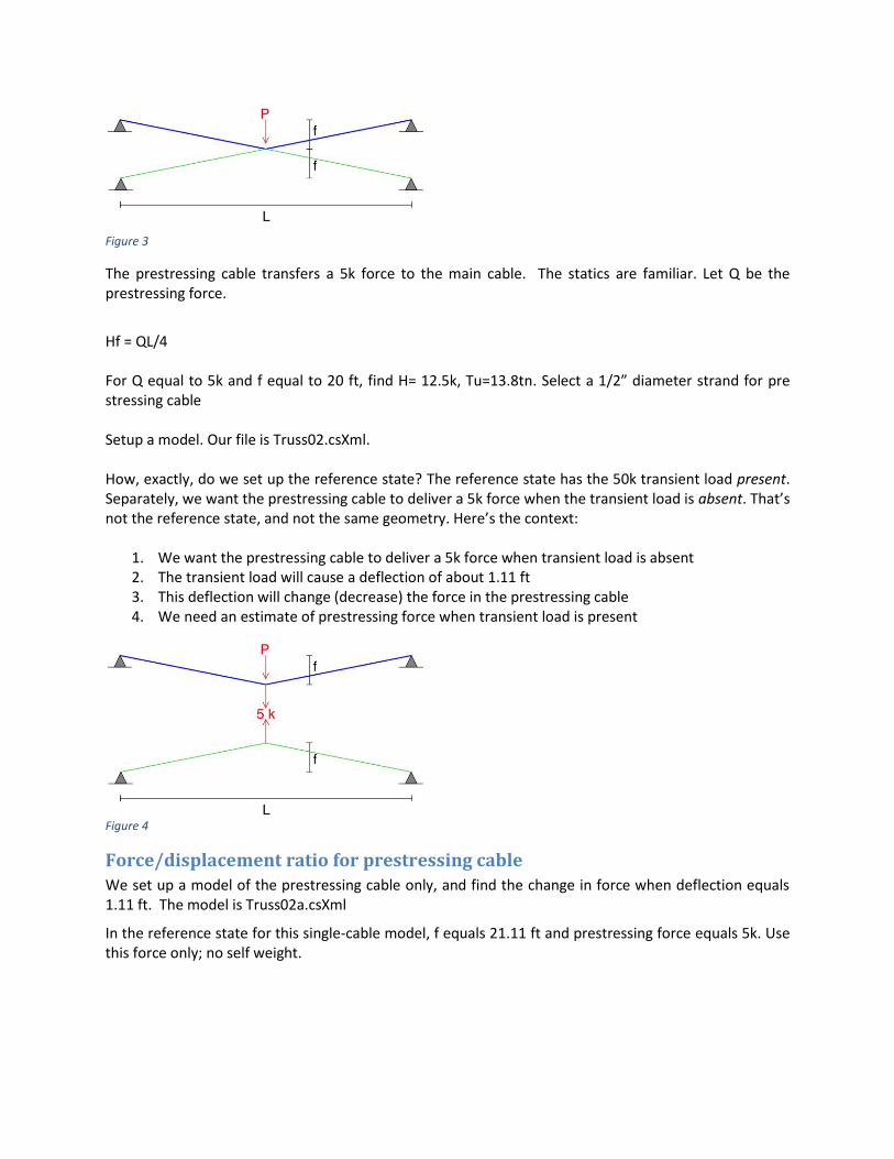
Figure 3
The prestressing cable transfers a 5k force to the main cable. The statics are familiar. Let Q be the prestressing force.
Hf = QL/4 For Q equal to 5k and f equal to 20 ft, find H= 12.5k, Tu=13.8tn. Select a 1/2” diameter strand for pre stressing cable Setup a model. Our file is Truss02.csXml. How, exactly, do we set up the reference state? The reference state has the 50k transient load present. Separately, we want the prestressing cable to deliver a 5k force when the transient load is absent. That’s not the reference state, and not the same geometry. Here’s the context:
1. We want the prestressing cable to deliver a 5k force when transient load is absent 2. The transient load will cause a deflection of about 1.11 ft 3. This deflection will change (decrease) the force in the prestressing cable 4. We need an estimate of prestressing force when transient load is present
Figure 4
Force/displacement ratio for prestressing cable
We set up a model of the prestressing cable only, and find the change in force when deflection equals 1.11 ft. The model is Truss02a.csXml
In the reference state for this single-cable model, f equals 21.11 ft and prestressing force equals 5k. Use this force only; no self weight.

Figure 5
For reference state
H = 11.72 k
Use a force displacement analysis to find the remaining prestressing force when deflection is 1.11 ft downward. Adjust the load factor for prestress load to get the remaining prestressing force.
Load Factor = 0.333
Remaining prestress force equals = 0.333 (5k) = 1.665 k
We want the prestressing cable to deliver 1.665k force to the main cable when the transient load is present.
Reference state for truss
The prestressing force is internal to the two-cable truss. We set up the reference state this way.
1. Find the z-coordinates for the prestressing calbe in the reference state. This is self-weight plus an external upward force at midspan equal to 1.665k. We use joint equilibrium relations to get z-coordinates.
2. Find the z-coordinates for the main cable in the reference state. This is self-weight plus an external downward force at midspan equal to 50k + 1.665k. We use joint equilibrium relations to get z-coordinates.
3. In the cable app, set H for the prestressing cable to zero, apply self weight load and 50k load, adjust H of main cable to get net upward out-of-balance equal to 1.665 k (limit in display precision is a issue here).
4. Adjust H in prestressing cable to get equilibrium at all points in both cables
H main cable = 131.6 k H prestressing cable = 4.08 k Report z-coordinates for reference state Table 11
ID X ft Y ft Z ft Sx Sy Sz
Left 0 0 1 1 1
a 20 -4.058205
b 40 -8.0873075
c 60 -12.087307
d 80 -16.058205
Mid 100 -20
e 120 -16.058205

ID X ft Y ft Z ft Sx Sy Sz
f 140 -12.087307
g 160 -8.0873075
h 180 -4.058205
Right 200 0 1 1 1
P Left 0 -40 1 1 1
i 20 -36.087556
j 40 -32.131334
k 60 -28.131334
l 80 -24.087556
100 -20
m 120 -24.087556
n 140 -28.131334
o 160 -32.131334
p 180 -36.087556
Use a force-displacement analysis to find deflection of the cable truss when transient load is absent. Deflections with transient load absent Table 12
ID Dx ft Dy ft Dz ft
Left 0 0 0 a 0 -0.08 -0.22 b 0 -0.12 -0.23 c 0 -0.12 -0.02 d 0 -0.08 0.41 Mid 0 0 1.05 e 0 0.08 0.41 f 0 0.12 -0.02 g 0 0.12 -0.23 h 0 0.08 -0.22 Right 0 0 0 P Left 0 0 0 i 0 -0.01 0.26 j 0 -0.01 0.49 k 0 -0.01 0.7 l 0 -0.01 0.89 m 0 0.01 0.89 n 0 0.01 0.7 o 0 0.01 0.49 p 0 0.01 0.26 P Right 0 0 0 The structure is OK for deflection

Check Cable strength
For main cable, use 2.2 load factor on all loads. We find
Tu main cable = 273 k, 2 3/8” strand is OK
Tu prestress cable = 0.71 k, 1/2” strand is OK
For prestressing cable, remove transient load. Keep load factor for self weight at 1.0
Tu main cable = 17.22 k, 2 3/8” strand is OK
Tu prestress cable = 12.77 k, 1/2” strand is OK