cad analysis lab manual 2015 s6 mechanical
DESCRIPTION
Laboratory manual for S6 Mechanical CAD ANALYSIS LAB, 2008 Scheme B.Tech Kerala UniversityTRANSCRIPT

ST.THOMAS INSTITUTE FOR
SCIENCE AND TECHNOLOGY
(STIST) THIRUVANANTHAPURAM
DEPARTMENT OF MECHANICAL ENGINEERING
CAD ANALYSIS LAB LABORATORY MANUAL
2015
DEPARTMENT OF MECHANICAL ENGINEERING
ST.THOMAS INSTITUTE FOR SCIENCE AND TECHNOLOGY THIRUVANANTHAPURAM
08.607 CAD ANALYSIS LAB
LABORATORY MANUAL
2015
Name:
Roll No:
CONTENTS
Title Page No.
Introduction to Solid Edge 1
PART 1: PART MODELING 6
Exercise 1 7
Exercise 2 7
Exercise 3 8
PART 2: ASSEMBLY MODELING 9
Exercise 4 10
Exercise 5 11
Exercise 6 12
Exercise 7 13
Exercise 8 14
Exercise 9 15
Exercise 10 16
Introduction to Femap 17
PART 3: ANALYSIS 20
Exercise 11 21
Exercise 12 21
Exercise 13 22
Exercise 14 22
Exercise 15 23
Exercise 16 23

Pag
e1
CAD Analysis Lab Manual S6 Mechanical DEPT OF MECHANICAL - STIST
INTRODUCTION TO SOLID EDGE
Solid Edge, a product of Siemens, is one of the world’s fastest growing solid modeling software. Solid Edge with Synchronous Technology combines the speed and flexibility of direct modeling with precise control of dimension-driven through precision sketching, region selection, face selection, and handle selection. Solid Edge ST4 integrates the synchronous modeling with the traditional modeling into a single environment. It is an integrated solid modeling tool, which not only unites the synchronous modeling with traditional modeling but also address every design-through-manufacturing process.
In Solid Edge, the 2D drawing views can be easily generated in the drafting environment after creating solid models and assemblies. The drawing views that can be generated include orthographic views, isometric views, auxiliary views, section views, detail views and so on. The user can use any predefined drawing standard file for generating the drawing views. The user can display model dimensions in the drawing views or add reference dimensions whenever he wants. The bidirectional associative nature of this software ensures that any modifications made in the model is automatically reflected in the drawing views.
To make the design process simple and efficient, the software package divides the steps of designing into different environments. This means, each step of the design process is completed in a different environment. Generally, a design process involves the following steps:
Sketching by using the basic sketch entities and converting them into features or parts. These parts can be sheet metal parts, surface parts or solid parts.
Assembling different parts and analyzing them
Generating drawing views of the parts and the assembly.
Solid Edge supports data migration from various CAD packages such as IDEAS, AutoCAD, Mechanical Desktop, Pro/E, Inventor, CATIA, and NX documents. As a result, all files and documents created in these software into a Solid Edge document.
Solid Edge Environments
To reduce the complications of a design, this software package provides you with various design environments.
a. Part Environment
This environment is used to create solid as well as surface models. The part environment consists of two environments namely Synchronous Part and Ordered Part. Synchronous is the default environment in ST4. In this environment, there is no separate environment to draw sketches; rather the sketching tools are available in the Synchronous Part environment itself.
b. Assembly Environment
This environment is used to create an assembly by assembling the components that were created in the Part environment. This environment supports animation, rendering, piping, and wiring.
c. Draft Environment
This environment is used for the documentation of the parts or the assemblies in the form of drawing views. The drawing views can be generated or created. All the dimensions added to

Pag
e2
CAD Analysis Lab Manual S6 Mechanical DEPT OF MECHANICAL - STIST
the component in the part environment during its creation can be displayed in the drawing views in this environment.
d. Sheet Metal Environment
This environment is used to create sheet metal components.
e. Weldment Environment
This environment enables you to insert components from the part or the assembly environment and apply weld beads to the parts or the assembly. This environment is associative with the part and assembly environment.
User Interface of Solid Edge
Prompt Line: If the user invoke a tool, the prompt line is displayed below the command bar. This line is very useful while creating a model, because it provides the user with the prompt sequences to use a tool.
PathFinder: The PathFinder is present on the left of the drawing area. It lists all occurences of features and sketches of a model in a chronicle sequences.
Docking Window: The docking window is available on the left of the screen and remains collapsed by default. It has different tabs on the top. These tabs can be used to activate the feature library, family of parts etc.
Ribbon: The Ribbon is available at the top of the solid edge window and contains all application tools. It is a collection of tabs. Each tab has different groups and each group is a collection of similar tools.
Quick Access toolbar: It is available on the top-left of the title bar of the solid edge window. It proves an access to the frequently used commands such as New, Open, Undo, Redo, Save and Print.
Application Button: It is available on the top left corner of the solid edge window. It is present in all environments. On choosing this button, the Application menu containing the options for creating, opening, saving, and managing documents will be displayed.
Status Bar: It is available at the bottom of the solid edge window. It enables the user to quickly access all the view controls like Zoom Area, Zoom, Fit, Pan, Rotate, Sketch View, View Orientation, and View styles.
QuickBar: It provides the command options for the active tool.
Assembly Environment Tabs: There are several tabs in the Ribbon that can be invoked in the part environment.
i. Homeii. Features iii. PMI iv. Simulation v. Simulation Geometry
vi. Inspect vii. Tools viii. View

Pag
e3
CAD Analysis Lab Manual S6 Mechanical DEPT OF MECHANICAL - STIST
Assembly Relationships
The assembly relationships are the logical operations that are performed on the component to assemble at their respective work in position in an assembly this relationship played to reduce the degrees of freedom of the components
Mate: This relationship is used to make the selected face of the different components coplanar. You can also specify some offset distance between the selected faces.
Planar Align: This relationship enables you to align a planar face with the other planar face.
Axial Align: This relationship enables you to make a cylindrical surface coaxial with the other cylindrical surface.
Insert: This relationship is used to mate the phases of two components that are actually symmetric and also to mate their axes coaxial.
Connect: This relationship enables you to connect two keypoints, line, or a face on two different parts.
Angle: This relationship is used to place the selected faces of different components at some angle with respect to each other.
Tangent: This relationship is used to make the selected face of a component tangent to the cylindrical, circular or conical faces of the other component.
Cam: This relationship applies the cam-follower relationship between a closed loop of tangent face and the follower face.
Parallel: The parallel relationship is used to force two edges, axes or an edge and an axis parallel to each other.
Gear: The gear a relationship allows you to apply rotation-rotation, rotation-linear, or a linear-linear relationship between two components.

Page4
Application Button
Quick Access toolbar Groups Ribbon
Base Coordinate System
PathFinder
View Orientation Triad
Status bar
Docking Window
Solid Edge ST4 Assembly environment
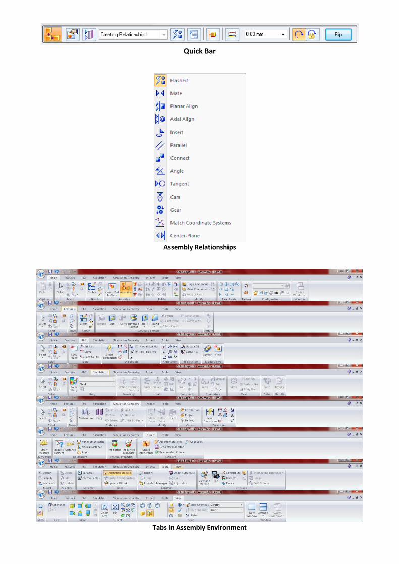
Quick Bar
Assembly Relationships
Tabs in Assembly Environment

PART 1: PART MODELING

CAD Analysis Lab Manual S6 Mechanical DEPT OF MECHANICAL - STIST
Pag
e7
Exercise 1
Exercise 2
Φ19
CAD Analysis Lab Manual S6 Mechanical DEPT OF MECHANICAL - STIST
Pag
e8
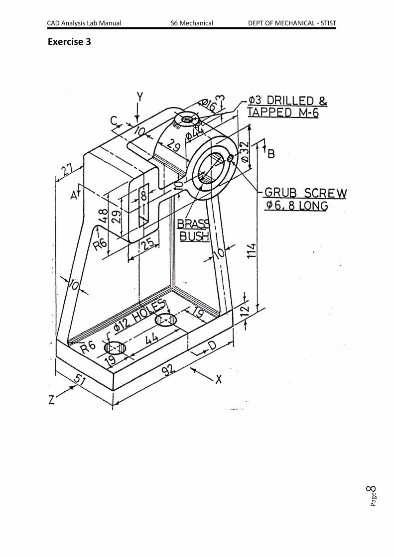
Exercise 3

PART 2: ASSEMBLY MODELING

CAD Analysis Lab Manual S6 Mechanical DEPT OF MECHANICAL - STIST
Pag
e10
Exercise 4: FLANGED COUPLING (Protected Type)

CAD Analysis Lab Manual S6 Mechanical DEPT OF MECHANICAL - STIST
Pag
e11
Exercise 5: UNIVERSAL COUPLING (Hook’s Joint)
CAD Analysis Lab Manual S6 Mechanical DEPT OF MECHANICAL - STIST
Pag
e12
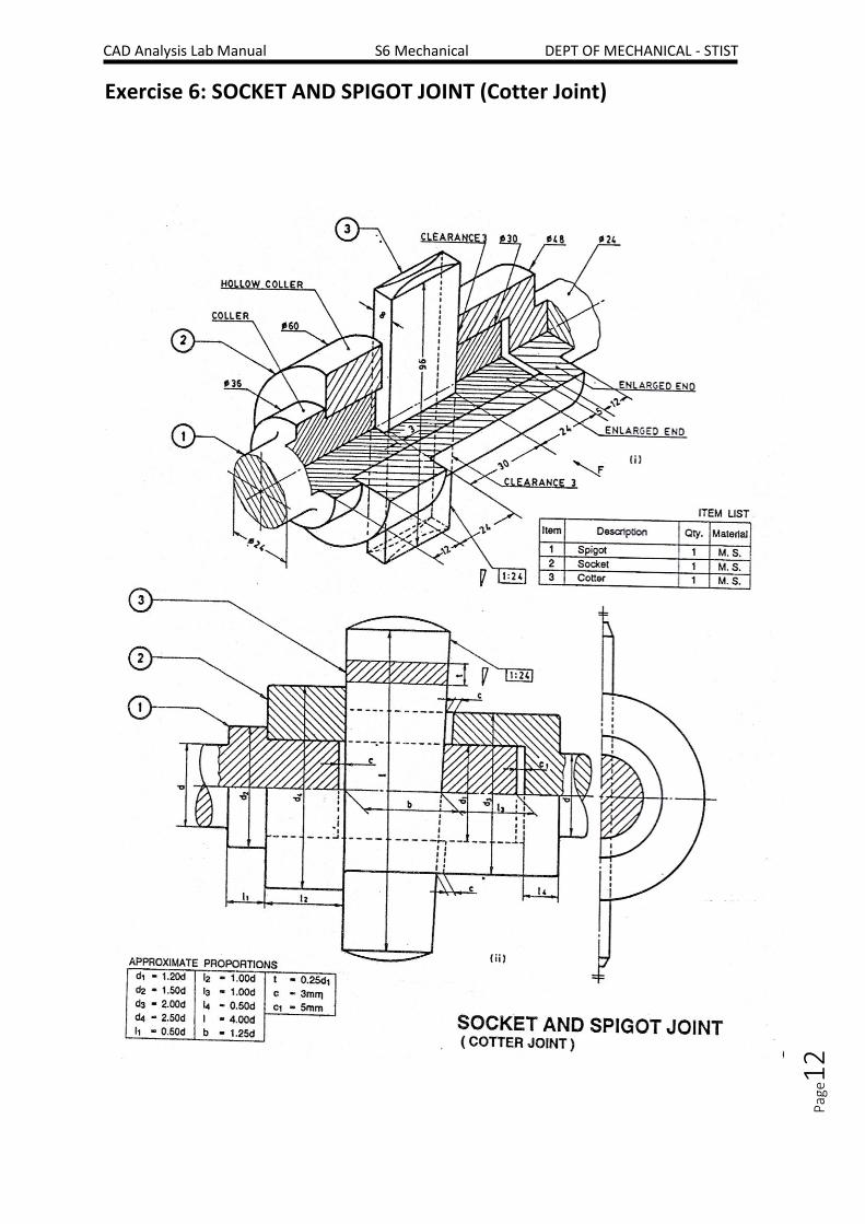
Exercise 6: SOCKET AND SPIGOT JOINT (Cotter Joint)

CAD Analysis Lab Manual S6 Mechanical DEPT OF MECHANICAL - STIST
Pag
e13
Exercise 7: SLEEVE AND COTTER JOINT (Cotter Joint with Sleeve)

CAD Analysis Lab Manual S6 Mechanical DEPT OF MECHANICAL - STIST
Pag
e14
Exercise 8: GIB AND COTTER JOINT (Strap Joint with Gib and Cotter)

CAD Analysis Lab Manual S6 Mechanical DEPT OF MECHANICAL - STIST
Pag
e15
Exercise 9: CROSS HEAD (Horizontal Type)

CAD Analysis Lab Manual S6 Mechanical DEPT OF MECHANICAL - STIST
Pag
e16
Exercise 10: KNUCKLE JOINT (Pin Joint)

CAD Analysis Lab Manual S6 Mechanical DEPT OF MECHANICAL - STIST
Pag
e17
INTRODUCTION TO FEMAP
Femap (Finite Element Modeling And Postprocessing) is an engineering analysis program sold
by Siemens PLM Software that is used to build finite element models of complex engineering
problems ("pre-processing") and view solution results ("post-processing"). It runs
on Microsoft Windows and provides CAD import, modeling and meshing tools to create a
finite element model, as well as postprocessing functionality that allows mechanical
engineers to interpret analysis results. The finite element method allows engineers to virtually
model components, assemblies, or systems to determine behavior under a given set of
boundary conditions, and is typically used in the design process to reduce costly prototyping
and testing, evaluate differing designs and materials, and for structural optimization to reduce
weight.
Product simulation applications include basic strength analysis, frequency and transient
dynamic simulation, system-level performance evaluation and advanced response, fluid flow
and multi-physics engineering analysis for simulation of functional performance.
Femap is used by engineering organizations and consultants to model complex products,
systems and processes including satellites, aircraft, defense electronics, heavy construction
equipment, lift cranes, marine vessels and process equipment.
Features of FEMAP
CAD-Independent
Femap is CAD-independent and can access geometry data from all major CAD systems
including CATIA, Pro/Engineer, NX, Solid Edge, SolidWorks and AutoCAD. Once imported you
can prepare the model for analysis using the geometry locator to identify and display
potentially troublesome entities, such as slivers, and either remove them completely with the
geometry cleanup tools or suppress them. Femap also offers a wealth of geometry creation
and modification functions so you can make necessary model changes in preparation for finite
element model creation.
Finite Element Modeling
The full finite element model with underlying data is fully exposed by Femap, allowing you to
view, create or modify entities directly. Femap’s grouping, layering and visualization tools
help you to manage model display while creating and setting up the finite element model.
Femap includes specialized capabilities to help with modeling tasks including:
Mid-plane extraction of thin-walled structures to aid creation of more efficient and
accurate shell models
Weldment modeling that connects discrete solid welded parts together into a
contiguous model
Data surfaces that allow you to create complex loading conditions based on prior
analysis output for multi-physics applications

CAD Analysis Lab Manual S6 Mechanical DEPT OF MECHANICAL - STIST
Pag
e18
Finite Element Meshing
Femap’s 3D solid and surface meshes are tuned to generate high-quality meshes, providing
well-shaped elements to ensure accurate results. Femap gives you full control over all mesh
generation parameters including mesh sizing, meshing of small features, growth factors, short
edge suppression, etc. With complex geometry, modification of the mesh is often required in
areas where greater accuracy is desired. For this situation Femap’s Meshing Toolbox allows
you to interactively modify mesh sizing parameters on the underlying geometry, and see the
mesh update automatically. You can also view element quality feedback live while modifying
the mesh, to ensure that a high-quality finite element model is created.
Assembly Modeling
Femap with NX Nastran supports assembly modeling, including automatic contact detection
that determines the components initially in contact. The contact regions can be set to be
simply in contact (with or without friction) or glued together. The contact calculations
performed by NX Nastran are iterative and update during the solution, to take into account
deformation changes representing the true contact condition in the final results.
Other types of component assembly modeling techniques also supported include spot-weld,
fastener elements, and bolted joints with optional pre-loading.
Beam Modeling
Besides solid and shell element models Femap also supports beam modeling and meshing.
This technique allows models comprising long, slender components (for which a solid meshing
approach would create a large, unwieldy model) to be represented by one-dimensional
elements with associated properties.
Model visualization is key to beam modeling, and with Femap you can view these elements
as solid components and include offsets. Femap features a section property editor which
includes a library of standard cross-section shapes. You can also define your own sections,
and the built-in section property calculator automatically determines the required properties.
Also available are full beam visualization and results display options including shear and
bending moment diagrams.
Composite Modeling
The use of composite materials in designs has increased significantly in recent years, and
Femap can help you model and postprocess results on composite structures. With Femap’s a
laminate editor and viewer, you can update the laminate properties interactively as you
create and modify plies in the laminate.
You can also postprocess composite laminate results using Femap’s global composite ply
feature, which allows you to view results on continuous plies through the structural model.
Solver Neutral
Femap is solver-neutral and provides in-depth pre- and postprocessing support for all of the
main commercial solvers on the market, including NX Nastran, Ansys, LS-DYNA, Abaqus and
TMG. You can take full advantage of the advanced analysis capabilities of these solvers using

CAD Analysis Lab Manual S6 Mechanical DEPT OF MECHANICAL - STIST
Pag
e19
Femap’s comprehensive modeling and analysis support, particularly for dynamic, geometric
and material nonlinear, heat transfer and fluid flow analyses.
Postprocessing
A wealth of visualization capabilities help you view and interpret the results to quickly
understand the model behavior. You’ll find everything you need to view and interpret the
output data, including:
Contour and criteria plots
Deformed shape animations
Dynamic cutting plane and iso-surfaces
Full output selection
XY plots
Free body diagrams and grid point force balance output
Time and frequency domain animations
Complete access to results data is provided through the Data Table pane, which you can use
to gather, sort and control the amount and type of data that is visible, to compile an analysis
report.
Scalable Simulation Solutions
The Velocity Series CAE products offer scalable solutions for design engineers in the form of
the CAD-embedded Solid Edge Simulation program, and Femap with NX Nastran for CAE
analysts.
The Femap with NX Nastran product line itself offers solution scalability, from the more
general simulation capabilities available in the base module to more advanced applications
including dynamics, optimization, advanced nonlinear, rotor dynamics, heat transfer and fluid
flow in add-on modules.
Customization
Femap’s open customization capability allows complete access to all Femap functions through
an OLE/COM object-oriented Application Programming Interface (API), which employs
standard, non-proprietary programming languages. Access to the API is through a
development environment within the user interface where you can create custom programs
that automate workflows and processes, and which can interact and exchange data with
third-party programs such as Microsoft Word and Excel.
Usability
Femap is an intuitive Windows-native application. Femap’s support of multiple graphics
windows and specialized panes, such as the Model Info Tree and Data Table, allow complete
access to the finite element model and results data and help promote efficient work flows.
You can modify the appearance of the interface to suit your requirements, including
repositioning panes, modifying the level of functionality exposed, and complete toolbar and
icon customization.

PART 3: ANALYSIS

CAD Analysis Lab Manual S6 Mechanical DEPT OF MECHANICAL - STIST
Pag
e21
Exercise 11: Find out the total axial deflection and reaction force at the fixed end of an axial
member of cross section 100x100mm and 1000mm long subjected to an axial
load of 1000N at the free end. The axial member is made of 4340 steel.
Exercise 12: Find the maximum deflection of a cantilever beam having a length of 1m and
cross section of 200 x 100 mm (where, 200mm is height). The load applied is 10
kN. E = 210 GPa.
CAD Analysis Lab Manual S6 Mechanical DEPT OF MECHANICAL - STIST
Pag
e22
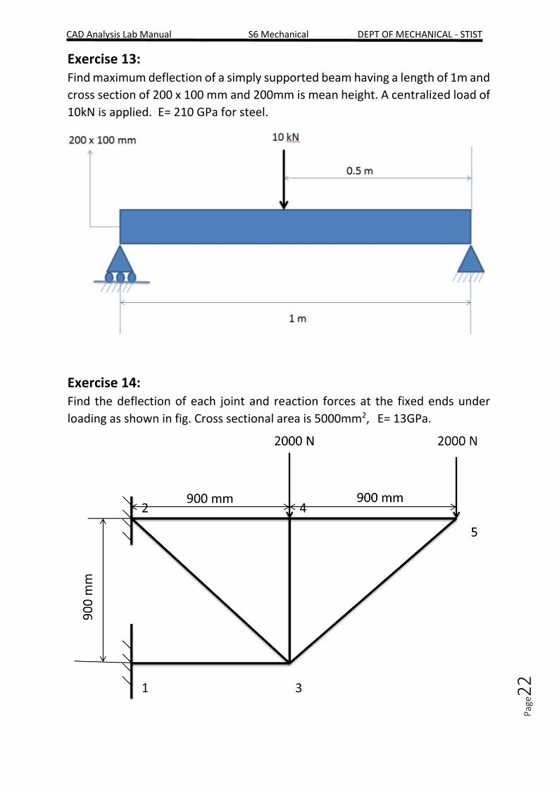
Exercise 13: Find maximum deflection of a simply supported beam having a length of 1m and
cross section of 200 x 100 mm and 200mm is mean height. A centralized load of
10kN is applied. E= 210 GPa for steel.
Exercise 14: Find the deflection of each joint and reaction forces at the fixed ends under
loading as shown in fig. Cross sectional area is 5000mm2, E= 13GPa.
CAD Analysis Lab Manual S6 Mechanical DEPT OF MECHANICAL - STIST
Pag
e23
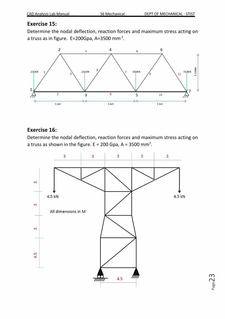
Exercise 15: Determine the nodal deflection, reaction forces and maximum stress acting on
a truss as in figure. E=200Gpa, A=3500 mm 2.
Exercise 16: Determine the nodal deflection, reaction forces and maximum stress acting on
a truss as shown in the figure. E = 200 Gpa, A = 3500 mm2.