cad standards for lawa projects · pdf fileand project partners prepare cad files for ......
TRANSCRIPT
CAD Standards for LAWA projects
CAD Standards for LAWA Projects

CAD Standards for LAWA projects
Document History
revision letter release date major changes approved by
A September 2012 new version of standards
B June 2014 General Review
C August 2014 IMTG GIS Support Services Division
CAD Standards for LAWA projects
CAD_Standards_August_2014.docx revision letter C revision date August 2014 © x‐Spatial LLC, 2014 Status: Published ii
Table of Contents
About this book ...................................................................................................................................... 1
Relation to existing standards ......................................................................................................... 1
Who should read this book ............................................................................................................. 1
How this book is organized ............................................................................................................. 2
Related documents ......................................................................................................................... 2
Abbreviations .................................................................................................................................. 3
Introduction ............................................................................................................................................ 4
Benefits of CAD Standards ............................................................................................................. 5
General principles ........................................................................................................................... 5
Templates ....................................................................................................................................... 5
Standards in use at LAWA .................................................................................................................... 6
LAWA standards ............................................................................................................................. 6
National and International standards .............................................................................................. 7
Compliance ..................................................................................................................................... 8
Request of Variance ....................................................................................................................... 8
Exporting Revit (.rvt) files to CAD (.dwg) ............................................................................................ 9
Drawing Organization .......................................................................................................................... 10
Model Space and Paper Space (Sheet files) ................................................................................ 10
Naming Conventions ..................................................................................................................... 10
Naming Conventions for Model Files ............................................................................................ 10
Examples.............................................................................................................................. 12
Naming Conventions for Sheet Files ............................................................................................ 13
Examples.............................................................................................................................. 14
Reference Files ............................................................................................................................. 15
Appearance and Presentation ............................................................................................................ 16
Lines .............................................................................................................................................. 16
Line weight ........................................................................................................................... 16
Line type (line style) ............................................................................................................. 17
Line color .............................................................................................................................. 18
Text ............................................................................................................................................... 19
Text styles and fonts ............................................................................................................ 19
Text sizes ............................................................................................................................. 20
Sheet organization ........................................................................................................................ 21
Sheet Size ............................................................................................................................ 21
Title Block ............................................................................................................................. 21
CAD Standards for LAWA projects
CAD_Standards_August_2014.docx revision letter C revision date August 2014 © x‐Spatial LLC, 2014 Status: Published ii
North arrow ................................................................................................................................... 22
Drawing scale ................................................................................................................................ 22
Dimensioning ................................................................................................................................ 22
Guidelines for layers ............................................................................................................................ 23
Layer Naming Convention ............................................................................................................ 23
Examples.............................................................................................................................. 24
Layer assignment .......................................................................................................................... 25
Symbols/Blocks ................................................................................................................................... 26
Appendix A. File type codes per discipline ....................................................................................... 27
CAD Standards for LAWA projects
CAD_Standards_August_2014.docx revision letter C revision date August 2014 © x‐Spatial LLC, 2014 Status: Published page 1 of 33
About this book
The standards described in this document are provided to help LAWA staff, consultants and project partners prepare CAD files for use in LAWA projects.
By using these standards, LAWA will achieve a standardized approach to spatial data management and related record document(s) that will bring many benefits to both the organization and its staff. These benefits include, but are not limited to:
consistent and more reliable data that will lead to more informed decision making
closer integration with other LAWA information systems and LAWA spatial data users
portability of staff skills
greater interoperability with organizations outside of LAWA
Relation to existing standards
These LAWA-specific standards are generally derived from version 5.0 of the United States National CAD Standard. More detailed topics such as layer guidelines also refer to the AIA standards.
Who should read this book
This book is intended for all LAWA project partners, and especially for members of their staff who prepare CAD drawings for use within a project. It is provided to promote and support effective implementation of CAD drawing standards within the airport, for the full project life-cycle.
CAD Standards for LAWA projects
CAD_Standards_August_2014.docx revision letter C revision date August 2014 © x‐Spatial LLC, 2014 Status: Published page 2 of 33
How this book is organized
After the introduction, this book contains the following chapters and appendixes:
Drawing organization
Introduces the ideas of model and sheet files, and gives the title, length and description of each component of a standard file-reference
Appearances and presentation
Covers standards for lines, text, sheet organization, north arrow, drawing scale, and dimensioning.
Layers
Explains how layers are used for organization in AutoCAD and gives standards – based on AIA CAD guidelines – for identifying them
Symbols
Introduces the ideas of standardizing block entities Appendix A. File type codes per discipline
List of valid file types per discipline
Related documents
BIM, GIS, Survey, Metadata and EDI standards along with other documentation related to these standards are available on the LAWA website. LAWA Standard Documents and Guidelines
CAD Standards for LAWA projects
CAD_Standards_August_2014.docx revision letter C revision date August 2014 © x‐Spatial LLC, 2014 Status: Published page 3 of 33
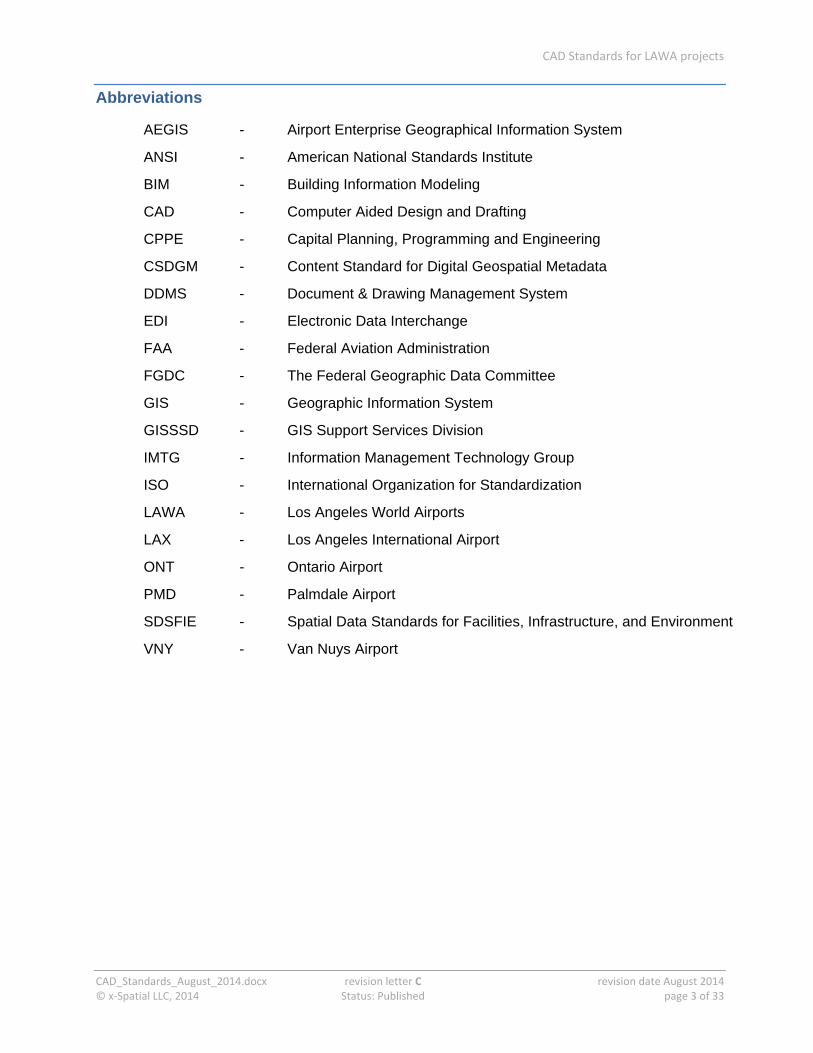
Abbreviations
AEGIS - Airport Enterprise Geographical Information System
ANSI - American National Standards Institute
BIM - Building Information Modeling
CAD - Computer Aided Design and Drafting
CPPE - Capital Planning, Programming and Engineering
CSDGM - Content Standard for Digital Geospatial Metadata
DDMS - Document & Drawing Management System
EDI - Electronic Data Interchange
FAA - Federal Aviation Administration
FGDC - The Federal Geographic Data Committee
GIS - Geographic Information System
GISSSD - GIS Support Services Division
IMTG - Information Management Technology Group
ISO - International Organization for Standardization
LAWA - Los Angeles World Airports
LAX - Los Angeles International Airport
ONT - Ontario Airport
PMD - Palmdale Airport
SDSFIE - Spatial Data Standards for Facilities, Infrastructure, and Environment
VNY - Van Nuys Airport

CAD Standards for LAWA projects
CAD_Standards_August_2014.docx revision letter C revision date August 2014 © x‐Spatial LLC, 2014 Status: Published page 4 of 33
Introduction
The standards cover the following aspects:
Drawing organization
How graphical information about a project is organized, including how the filenames for model files and the sheet files derived from them are built up.
Using agreed conventions makes it easy to identify the designer, location, discipline and subject of any file.
Drafting conventions
How information is presented in model files and sheet files, including standards for line width and color, fonts, and text orientation.
Using agreed drafting conventions helps ensure consistency through all related files, which makes it easier to compare and exchange information.
Layer-structure
How information (including blocks) is presented consistently on the appropriate layer.
Using agreed layers makes it easy to extraction and visualize information within a file or a set of files, and makes it easier to exchange files.
Symbols
Standard symbols used on CAD files throughout the airport environment.
Using agreed symbols helps ensure consistency, and reduces the effort required to create new files.
AllfilesanddocumentssubmittedtoLAWAmustbeaccompaniedbyatransmittalformholdingallrequiredmetadata.
TransmittalformsalongwithotherdocumentationrelatedtothesestandardsareavailableontheLAWAwebsite. LAWA Standard Documents and Guidelines
CAD Standards for LAWA projects
CAD_Standards_August_2014.docx revision letter C revision date August 2014 © x‐Spatial LLC, 2014 Status: Published page 5 of 33
Benefits of CAD Standards
Drawing up and implementing detailed standards for CAD files standards is intended to ensure a smooth flow of information at every stage of the project. Consistent, comparable files bring benefits that include the following:
project partners can share information confidently and easily
common format and comparable detail references are used for all projects within LAWA
information is presented in the same place in each set of drawing files
non-compliance and other errors can be quickly detected, reducing the need for change requests
data can easily be translated between languages and file-formats; document storage and retrieval can be automated
General principles
except for some specialized schematics, the software used to produce CAD drawings is AutoCAD (a recent version)
the unit of measurement used for CAD architectural drawings is the inch
the unit of measurement used for CAD civil drawings is the U.S. foot
project codes are defined by LAWA on a project per project basis
all civil drawings must be created in NAD 83 California State Planes, Zone V, US Foot coordinate system
all civil drawings will identify the survey epoch used, for example NSRS 2007, CORS 96, etc..
all architectural drawings must use positive values for coordinates
all spatial data must be created in “Model Space”
all graphical elements must be in “Paper Space”
Templates
Project partners and subcontractors who need to implement the CAD standards for LAWA projects can download templates to provide a working environment based on the LAWA CAD Standards. Each template (.dwt file) defines the layers for a specific discipline. Sample title blocks can also be downloaded.

CAD Standards for LAWA projects
CAD_Standards_August_2014.docx revision letter C revision date August 2014 © x‐Spatial LLC, 2014 Status: Published page 6 of 33
Standards in use at LAWA
LAWA standards
This section provides an overview of LAWA specific standards, plus related federal, local, and national standards. LAWA standards have been created to improve productivity and reliable information exchange through the full life-cycle of geospatial data, CAD and BIM files along with related documents.
LAWA Metadata Standards
Metadata is structured information that describes, explains, locates, or otherwise makes it easier to retrieve, use, or manage an information resource. Metadata is often called data about data or information about information.
LAWA GIS Standards
The LAWA GIS standards are directly based on the ANSI Spatial Data Standard for Facilities Infrastructure and Environment (SDSFIE), Release 2.60, extended in certain areas to handle specific information relevant to LAWA. GIS Standards for LAWA Projects presents the most important aspects of SDSFIE as it applies to LAWA.
LAWA Survey Standards
The LAWA Survey and Remote Sensing Standards are based on requirements laid out in Airport Circulars published by the FAA, adapted where necessary to suit LAWA-specific requirements.
LAWA BIM Standards
These guidelines focus primarily on adaptation of standards for practical and efficient application of BIM, particularly at the handover (Record - As-Built) stage of a project. Based on USACE_CAD-BIM_Technology Center: version 1.1 and National BIM standard (United States): version2
LAWA EDI (Electronic Data Interchange) Standards
This Standard provides a framework for all data requests and all hard copy or electronic data submittals to or from LAWA, thus ensuring a streamlined data exchange process
ThesestandardsalongwithotherdocumentationrelatedtothesestandardsareavailableontheLAWAwebsite. LAWA Standard Documents and Guidelines

CAD Standards for LAWA projects
CAD_Standards_August_2014.docx revision letter C revision date August 2014 © x‐Spatial LLC, 2014 Status: Published page 7 of 33
National and International standards
AIA CAD Layer Guidelines and the National CAD Standards (NCS)
The LAWA CAD standards are based largely on the AIA CAD Layer Guidelines and the National CAD Standards (NCS), adapted where necessary to suit LAWA-specific requirements.
SDSFIE 2.6
The overall structure of LAWA current geospatial repository is based on SDSFIE 2.6.
SDSFIE organizes real world features such as runways, roads and water pipes into a hierarchical structure.

CAD Standards for LAWA projects
CAD_Standards_August_2014.docx revision letter C revision date August 2014 © x‐Spatial LLC, 2014 Status: Published page 8 of 33
Compliance
Having timely up to date, accurate, fully compliant data available to the LAWA community forms an integral part of planning within any project. The aim of these standards is to ensure a smooth data transfer of information into the LAWA geospatial data base and efficient data maintenance through the complete data lifecycle. Accordingly, the terms and conditions of a LAWA contract require compliance with these standards.
Failure to comply with these standards may result in organizations being back-charged for any financial costs incurred by LAWA for rectifying inconsistencies and errors
The individual or organization submitting the files is also responsible for ensuring that all links between non-graphic data and graphic data, and all relationships between database tables, shall be preserved or automatically reconstructed when data is transferred to the LAWA GIS environment.
Request of Variance
Compliance with the LAWA standards and data deliverables demands are the cornerstone of achieving trustworthy and relevant data.
Suggestions for improvements or extensions to these standards and demands are encouraged, to meet unforeseen requirements and as a way to improve effectiveness and clarify any ambiguities; any such deviation must be approved by LAWA, in advance and in writing. . Requests need to be submitted on the “Request for variance” form, this form along with other documentation related to these standards are available on the LAWA website. LAWA Standard Documents and Guidelines
SeeEDIforstandardsgoverningdatasubmittedtoLAWA,thisalongwithotherdocumentationrelatedtothesestandardsareavailableontheLAWAwebsite. LAWA Standard Documents and Guidelines
CAD Standards for LAWA projects
CAD_Standards_August_2014.docx revision letter C revision date August 2014 © x‐Spatial LLC, 2014 Status: Published page 9 of 33
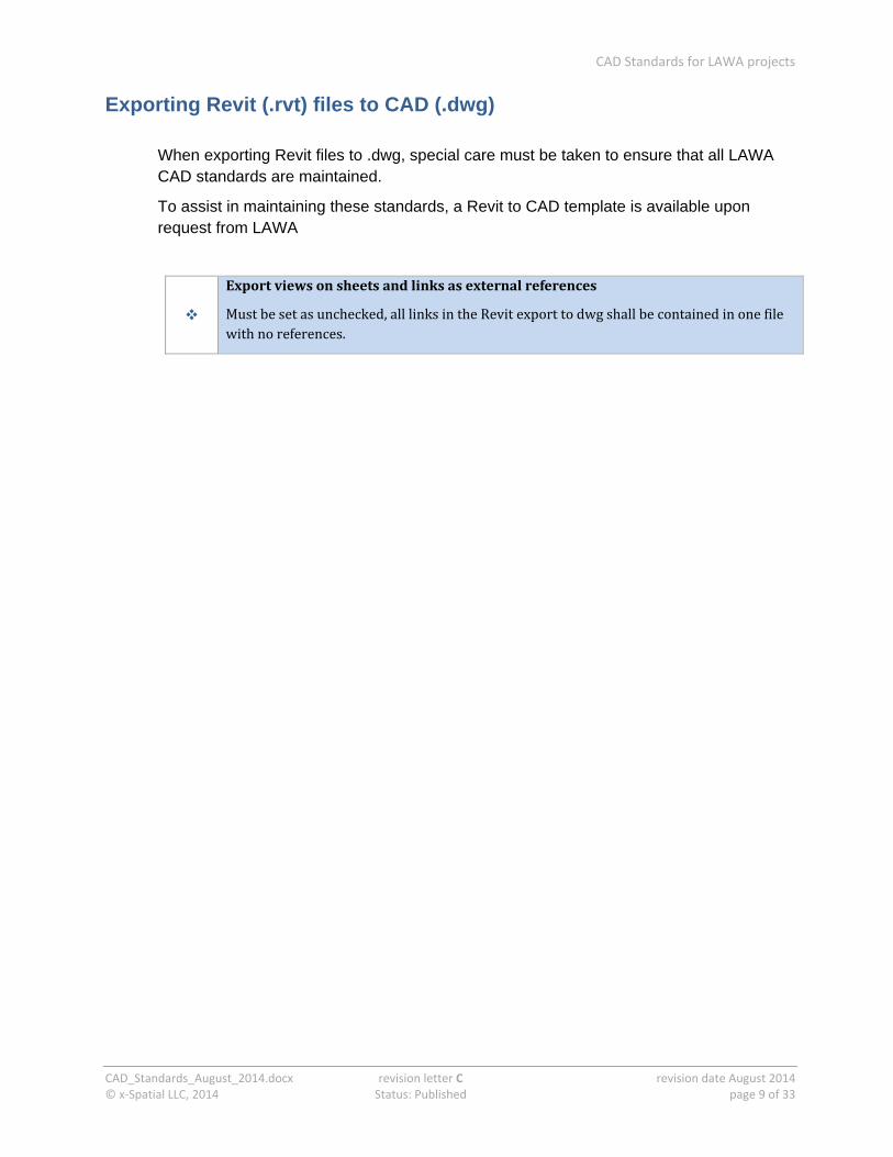
Exporting Revit (.rvt) files to CAD (.dwg)
When exporting Revit files to .dwg, special care must be taken to ensure that all LAWA CAD standards are maintained.
To assist in maintaining these standards, a Revit to CAD template is available upon request from LAWA
Exportviewsonsheetsandlinksasexternalreferences
Mustbesetasunchecked,alllinksintheRevitexporttodwgshallbecontainedinonefilewithnoreferences.

CAD Standards for LAWA projects
CAD_Standards_August_2014.docx revision letter C revision date August 2014 © x‐Spatial LLC, 2014 Status: Published page 10 of 33
Drawing Organization
This section covers CAD model files and sheet files, naming conventions, and external reference files.
Model Space and Paper Space (Sheet files)
AutoCAD has two distinct working spaces to create drawing objects, a model space and a paper space. All drawings for LAWA should have properly organized model and paper spaces:
model space is for creating a model or drawing composed of geometric objects
All data representing features must be drawn in the model space
paper space is used for plots (sheet files) of drawings created in model space
Paper space usually contains single or multiple viewports of a model, any specified scale and orientation, a title block, a north arrow, a legend, and a scale bar. Any descriptive text for a drawing (other than dimensions or object-related notes) must be placed in a paper space view.
Naming Conventions
Naming conventions for electronic drawing files (model files and sheet files) allow users to identify the content and relevance of the drawing. They provide basic minimum information for organizing the files within a project directory and or entering them into an electronic document management system.
Naming Conventions for Model Files
Model file names are made up of four mandatory elements, which must be used in the correct sequence. These names are structured to ensure consistency among different disciplines within the project.
the first two elements are the unique project code and the discipline designator, followed by a hyphen
the file type is a two-character code describing the content of the file
a project-specific code identifying the coverage of the model file
the extension (a period or stop followed by three letters) identifying the file format, for example .dwg
CAD Standards for LAWA projects
CAD_Standards_August_2014.docx revision letter C revision date August 2014 © x‐Spatial LLC, 2014 Status: Published page 11 of 33
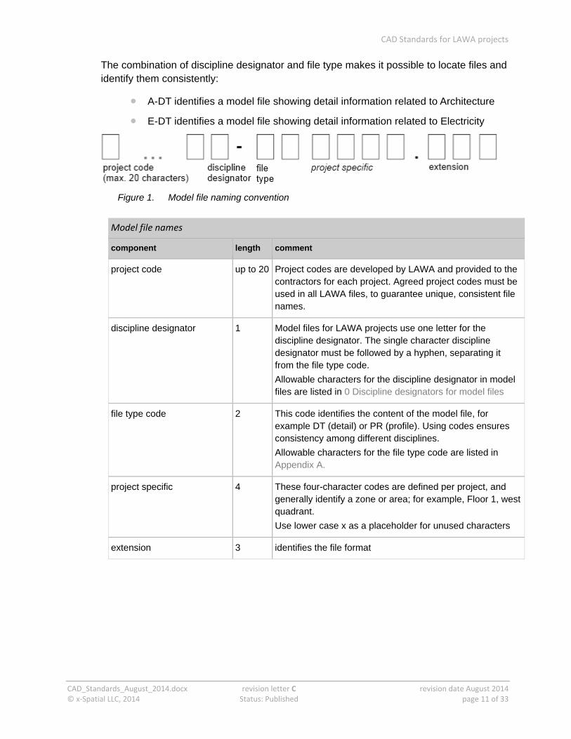
The combination of discipline designator and file type makes it possible to locate files and identify them consistently:
A-DT identifies a model file showing detail information related to Architecture
E-DT identifies a model file showing detail information related to Electricity
Figure 1. Model file naming convention
Model file names
component length comment
project code up to 20 Project codes are developed by LAWA and provided to the contractors for each project. Agreed project codes must be used in all LAWA files, to guarantee unique, consistent file names.
discipline designator 1 Model files for LAWA projects use one letter for the discipline designator. The single character discipline designator must be followed by a hyphen, separating it from the file type code.
Allowable characters for the discipline designator in model files are listed in 0 Discipline designators for model files
file type code 2 This code identifies the content of the model file, for example DT (detail) or PR (profile). Using codes ensures consistency among different disciplines.
Allowable characters for the file type code are listed in Appendix A.
project specific 4 These four-character codes are defined per project, and generally identify a zone or area; for example, Floor 1, west quadrant.
Use lower case x as a placeholder for unused characters
extension 3 identifies the file format
CAD Standards for LAWA projects
CAD_Standards_August_2014.docx revision letter C revision date August 2014 © x‐Spatial LLC, 2014 Status: Published page 12 of 33
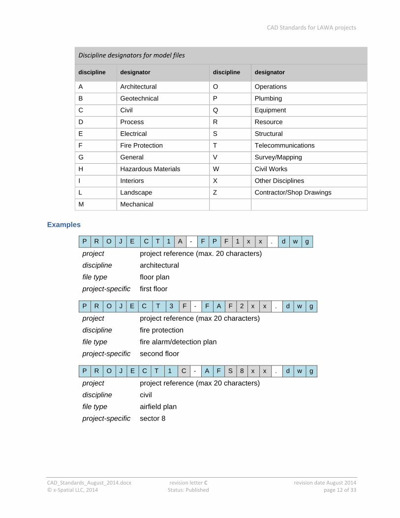
Discipline designators for model files
discipline designator discipline designator
A Architectural O Operations
B Geotechnical P Plumbing
C Civil Q Equipment
D Process R Resource
E Electrical S Structural
F Fire Protection T Telecommunications
G General V Survey/Mapping
H Hazardous Materials W Civil Works
I Interiors X Other Disciplines
L Landscape Z Contractor/Shop Drawings
M Mechanical
Examples
P R O J E C T 1 A - F P F 1 x x . d w g
project project reference (max. 20 characters)
discipline architectural
file type floor plan
project-specific first floor
P R O J E C T 3 F - F A F 2 x x . d w g
project project reference (max 20 characters)
discipline fire protection
file type fire alarm/detection plan
project-specific second floor
P R O J E C T 1 C - A F S 8 x x . d w g
project project reference (max 20 characters)
discipline civil
file type airfield plan
project-specific sector 8
CAD Standards for LAWA projects
CAD_Standards_August_2014.docx revision letter C revision date August 2014 © x‐Spatial LLC, 2014 Status: Published page 13 of 33
Naming Conventions for Sheet Files
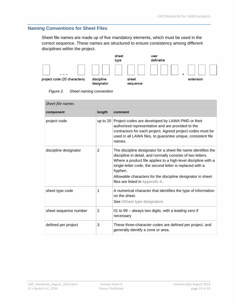
Sheet file names are made up of five mandatory elements, which must be used in the correct sequence. These names are structured to ensure consistency among different disciplines within the project.
Figure 2. Sheet naming convention
Sheet file names
component length comment
project code up to 20 Project codes are developed by LAWA PMD or their authorized representative and are provided to the contractors for each project. Agreed project codes must be used in all LAWA files, to guarantee unique, consistent file names.
discipline designator 2 The discipline designator for a sheet file name identifies the discipline in detail, and normally consists of two letters. Where a product file applies to a high-level discipline with a single-letter code, the second letter is replaced with a hyphen.
Allowable characters for the discipline designator in sheet files are listed in Appendix A.
sheet type code 1 A numerical character that identifies the type of information on the sheet.
See 0Sheet type designators
sheet sequence number 2 01 to 99 – always two digits, with a leading zero if necessary
defined per project 3 These three-character codes are defined per project, and generally identify a zone or area.
CAD Standards for LAWA projects
CAD_Standards_August_2014.docx revision letter C revision date August 2014 © x‐Spatial LLC, 2014 Status: Published page 14 of 33
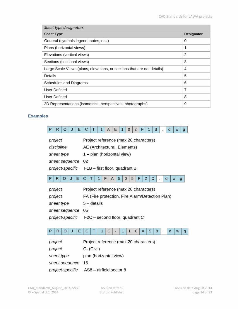
Sheet type designators
Sheet Type Designator
General (symbols legend, notes, etc.) 0
Plans (horizontal views) 1
Elevations (vertical views) 2
Sections (sectional views) 3
Large Scale Views (plans, elevations, or sections that are not details) 4
Details 5
Schedules and Diagrams 6
User Defined 7
User Defined 8
3D Representations (isometrics, perspectives, photographs) 9
Examples
P R O J E C T 1 A E 1 0 2 F 1 B . d w g
project Project reference (max 20 characters)
discipline AE (Architectural, Elements)
sheet type 1 – plan (horizontal view)
sheet sequence 02
project-specific F1B – first floor, quadrant B
P R O J E C T 1 F A 5 0 5 F 2 C . d w g
project Project reference (max 20 characters)
project FA (Fire protection, Fire Alarm/Detection Plan)
sheet type 5 – details
sheet sequence 05
project-specific F2C – second floor, quadrant C
P R O J E C T 1 C - 1 1 6 A S 8 . d w g
project Project reference (max 20 characters)
project C- (Civil)
sheet type plan (horizontal view)
sheet sequence 16
project-specific AS8 – airfield sector 8
CAD Standards for LAWA projects
CAD_Standards_August_2014.docx revision letter C revision date August 2014 © x‐Spatial LLC, 2014 Status: Published page 15 of 33
Reference Files
Using reference files is recommended and promoted in LAWA projects, because:
they make it possible to work with smaller files
they allow different people to work on different project drawings (for example, drawings from different disciplines) at the same time
every time a drawing using references file is loaded, the user sees the most recent version of the drawing
IMPORTANT Drawings using reference files must be stored in the same directory/ subdirectory as the files they refer to.
External references to other CAD files may be used to manage the content of a large CAD drawing as several smaller, more efficient drawings. The use of this procedure will reduce drawing size, increase performance, improve operator efficiency and make coordination of disciplines easier.

CAD Standards for LAWA projects
CAD_Standards_August_2014.docx revision letter C revision date August 2014 © x‐Spatial LLC, 2014 Status: Published page 16 of 33
Appearance and Presentation
This chapter covers standards for lines, text, sheet organization, north arrow, drawing scale, and dimensioning.
Lines
Standards for line drawing cover:
line weight
line type (line style)
line color
Line weight
Using the correct line width makes drawings more readable, by making more important information stand out.
wider lines draw attention to the part of the drawing where they are used, and place emphasis on certain elements
screen or half-tone lines de-emphasize drawing elements
The line weights to be used for each feature type in LAWA project drawings are available on the LAWA website. Typical use for line weights from Fine to XXXX Wide are described in the next table.
Typical line weight usage
line weight width (mm)
width (inch)
usage
Fine
0.18 0.007 Material indications, surface marks, hatch lines, patterns
Thin
0.25 0.010 Dimension lines, leaders, extension lines, break lines,
hidden objects, dotted lines, dashed lines, setback lines, center lines, grid lines, schedule grid lines
Medium
0.35 0.014 Object lines, property lines, text, lettering, terminator
marks, door and window elevations, schedule grid accent lines
Wide
0.50 0.020 Titles, edges of interior and exterior elevations, profiling;
cut lines, property lines, section cutting plane lines, drawing block borders
Extra wide 0.70 0.028 Minor title underlining, schedule outlines, large titles, and
CAD Standards for LAWA projects
CAD_Standards_August_2014.docx revision letter C revision date August 2014 © x‐Spatial LLC, 2014 Status: Published page 17 of 33
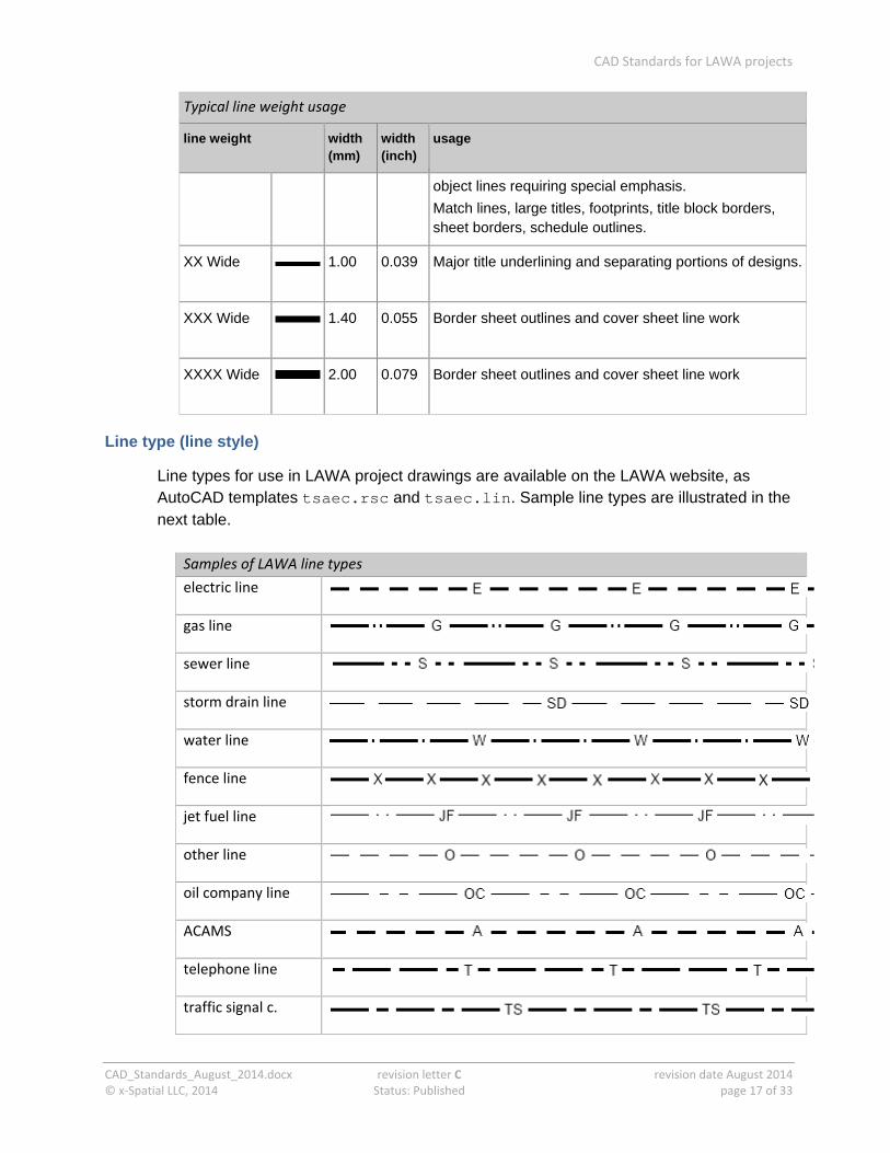
Typical line weight usage
line weight width (mm)
width (inch)
usage
object lines requiring special emphasis.
Match lines, large titles, footprints, title block borders, sheet borders, schedule outlines.
XX Wide
1.00 0.039 Major title underlining and separating portions of designs.
XXX Wide
1.40 0.055 Border sheet outlines and cover sheet line work
XXXX Wide
2.00 0.079 Border sheet outlines and cover sheet line work
Line type (line style)
Line types for use in LAWA project drawings are available on the LAWA website, as AutoCAD templates tsaec.rsc and tsaec.lin. Sample line types are illustrated in the next table.
Samples of LAWA line types
electric line
gas line
sewer line
storm drain line
water line
fence line
jet fuel line
other line
oil company line
ACAMS
telephone line
traffic signal c.
CAD Standards for LAWA projects
CAD_Standards_August_2014.docx revision letter C revision date August 2014 © x‐Spatial LLC, 2014 Status: Published page 18 of 33
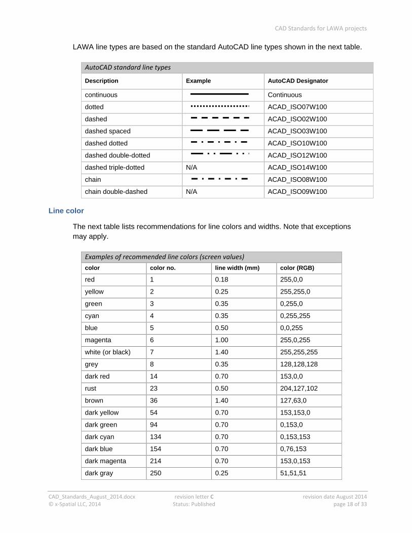
LAWA line types are based on the standard AutoCAD line types shown in the next table.
AutoCAD standard line types
Description Example AutoCAD Designator
continuous Continuous
dotted ACAD_ISO07W100
dashed ACAD_ISO02W100
dashed spaced ACAD_ISO03W100
dashed dotted ACAD_ISO10W100
dashed double-dotted ACAD_ISO12W100
dashed triple-dotted N/A ACAD_ISO14W100
chain ACAD_ISO08W100
chain double-dashed N/A ACAD_ISO09W100
Line color
The next table lists recommendations for line colors and widths. Note that exceptions may apply.
Examples of recommended line colors (screen values)
color color no. line width (mm) color (RGB)
red 1 0.18 255,0,0
yellow 2 0.25 255,255,0
green 3 0.35 0,255,0
cyan 4 0.35 0,255,255
blue 5 0.50 0,0,255
magenta 6 1.00 255,0,255
white (or black) 7 1.40 255,255,255
grey 8 0.35 128,128,128
dark red 14 0.70 153,0,0
rust 23 0.50 204,127,102
brown 36 1.40 127,63,0
dark yellow 54 0.70 153,153,0
dark green 94 0.70 0,153,0
dark cyan 134 0.70 0,153,153
dark blue 154 0.70 0,76,153
dark magenta 214 0.70 153,0,153
dark gray 250 0.25 51,51,51

CAD Standards for LAWA projects
CAD_Standards_August_2014.docx revision letter C revision date August 2014 © x‐Spatial LLC, 2014 Status: Published page 19 of 33
Examples of recommended line colors (screen values)
color color no. line width (mm) color (RGB)
med/dark gray 251 0.35 91,91,91
med/light gray 252 0.50 132,132,132
Text
Standards for text cover:
text styles and fonts
text size
Text styles and fonts
Different text styles and fonts are used within all LAWA project drawings to identify different types of information.
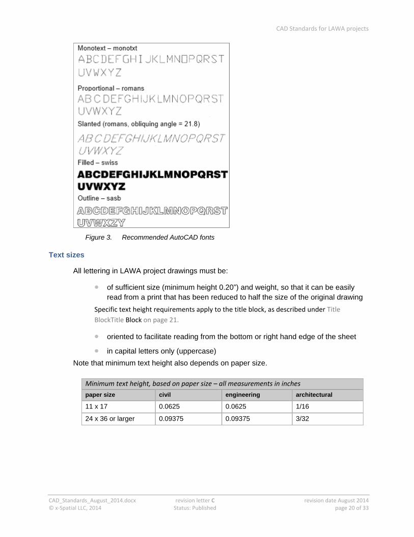
The five approved text styles are:
monotext (AutoCAD monotext font)
proportional (AutoCAD Romans font, with a width factor of 0.8)
slanted (AutoCAD Romans font with Obliquing Angle set to 21.8 deg to achieve the American Standard slope of 2 in 5
filled (AutoCAD Swiss TrueType font, with the TEXTFILL system variable set to 1 arialbd.ttf (Microsoft) can be used as an alternative
outline (AutoCAD Sasb (Sans Serif-bold) PostScript font :
Typical uses for text styles
usage text style
schedules, title blocks and other aligned text fields with evenly spaced characters
monotext
general notes, labels, or title blocks with proportionally spaced characters
proportional
text that needs to stand out from other text around it slanted
titles and cover sheets filled
major titles such as cover sheet information, when using a pen plotter for final output
outline
CAD Standards for LAWA projects
CAD_Standards_August_2014.docx revision letter C revision date August 2014 © x‐Spatial LLC, 2014 Status: Published page 20 of 33
Figure 3. Recommended AutoCAD fonts
Text sizes
All lettering in LAWA project drawings must be:
of sufficient size (minimum height 0.20”) and weight, so that it can be easily read from a print that has been reduced to half the size of the original drawing
Specific text height requirements apply to the title block, as described under Title
BlockTitle Block on page 21.
oriented to facilitate reading from the bottom or right hand edge of the sheet
in capital letters only (uppercase)
Note that minimum text height also depends on paper size.
Minimum text height, based on paper size – all measurements in inches
paper size civil engineering architectural
11 x 17 0.0625 0.0625 1/16
24 x 36 or larger 0.09375 0.09375 3/32
CAD Standards for LAWA projects
CAD_Standards_August_2014.docx revision letter C revision date August 2014 © x‐Spatial LLC, 2014 Status: Published page 21 of 33
Sheet organization
Sheet organization primarily involves sheet size and title block.
Sheet Size
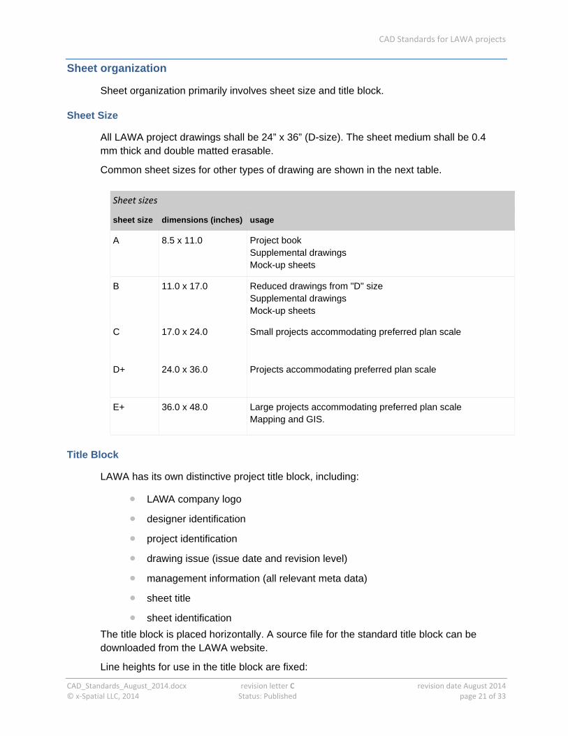
All LAWA project drawings shall be 24” x 36” (D-size). The sheet medium shall be 0.4 mm thick and double matted erasable.
Common sheet sizes for other types of drawing are shown in the next table.
Sheet sizes
sheet size dimensions (inches) usage
A 8.5 x 11.0 Project book Supplemental drawings Mock-up sheets
B 11.0 x 17.0 Reduced drawings from "D" size Supplemental drawings Mock-up sheets
C 17.0 x 24.0
Small projects accommodating preferred plan scale
D+ 24.0 x 36.0
Projects accommodating preferred plan scale
E+ 36.0 x 48.0
Large projects accommodating preferred plan scale Mapping and GIS.
Title Block
LAWA has its own distinctive project title block, including:
LAWA company logo
designer identification
project identification
drawing issue (issue date and revision level)
management information (all relevant meta data)
sheet title
sheet identification
The title block is placed horizontally. A source file for the standard title block can be downloaded from the LAWA website.
Line heights for use in the title block are fixed:
CAD Standards for LAWA projects
CAD_Standards_August_2014.docx revision letter C revision date August 2014 © x‐Spatial LLC, 2014 Status: Published page 22 of 33
Line 1: letter height 0.140 inches
Line 2: letter height 0.290 inches:
Line 3: letter height 0.200 inches
Line 4: letter height 0.200 inches
The general rules for line widths may not always apply in title blocks.
North arrow
By default, the project North arrow symbol shall be placed beneath the extension of the top line of the title block. Exceptionally, the arrow may be placed where cartographically feasible.
Drawing scale
Every sheet shall indicate the scale of the drawing, both as a ratio and as a graphical scale bar. In order of preference, graphical scale bars shall be placed:
1 beneath the extension of the top line of the title block
2 above the title block
3 where cartographically feasible
Where a single sheet includes drawings at different scales, for example a main drawing and a detail shown at a larger scale, every drawing must have its own scale indicators.
Dimensioning
All useful measurements must be indicated as dimensions. The letter height used for dimensions must be easily readable from a print that has been reduced to half the size of the original drawing. Additionally:
dimension figures shall be lettered parallel to and above the dimension line, and arranged to read from the bottom border or right hand border;
within a single sheet, care must be taken to show each dimension only once, and in its proper location
where dimensions cross the match-lines between two sheets, they shall be repeated on both sheets
dimension styles for both architectural and site plan drawings have been created at various scales for AutoCAD. These dimension styles are included in the AutoCAD templates provided for the project.
CAD Standards for LAWA projects
CAD_Standards_August_2014.docx revision letter C revision date August 2014 © x‐Spatial LLC, 2014 Status: Published page 23 of 33
Guidelines for layers
Layers are a key organizational tool used in all LAWA projects for AutoCAD files:
to separate graphic elements (lines, shapes, and text) according to the design discipline and feature type they represent
to enforce line-type, color and other standards
Layer 0 is a neutral layer which should be kept ‘clean’, with status always thawed and on.
Layers must be identified according to the standards for LAWA projects.
Detailed standard layer tables are available on the LAWA website.
Layer Naming Convention
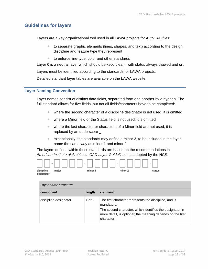
Layer names consist of distinct data fields, separated from one another by a hyphen. The full standard allows for five fields, but not all fields/characters have to be completed:
where the second character of a discipline designator is not used, it is omitted
where a Minor field or the Status field is not used, it is omitted
where the last character or characters of a Minor field are not used, it is replaced by an underscore _
exceptionally, the standards may define a minor 3, to be included in the layer name the same way as minor 1 and minor 2
The layers defined within these standards are based on the recommendations in American Institute of Architects CAD Layer Guidelines, as adopted by the NCS.
Layer name structure
component length comment
discipline designator 1 or 2 The first character represents the discipline, and is mandatory.
The second character, which identifies the designator in more detail, is optional; the meaning depends on the first character.
CAD Standards for LAWA projects
CAD_Standards_August_2014.docx revision letter C revision date August 2014 © x‐Spatial LLC, 2014 Status: Published page 24 of 33
Layer name structure
component length comment
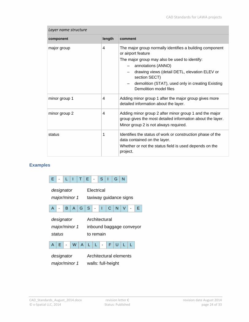
major group 4 The major group normally identifies a building component or airport feature
The major group may also be used to identify:
– annotations (ANNO)
– drawing views (detail DETL, elevation ELEV or section SECT)
– demolition (STAT), used only in creating Existing Demolition model files
minor group 1 4 Adding minor group 1 after the major group gives more detailed information about the layer.
minor group 2 4 Adding minor group 2 after minor group 1 and the major group gives the most detailed information about the layer.
Minor group 2 is not always required.
status 1 Identifies the status of work or construction phase of the data contained on the layer.
Whether or not the status field is used depends on the project.
Examples
E - L I T E - S I G N
designator Electrical
major/minor 1 taxiway guidance signs
A - B A G S - I C N V - E
designator Architectural
major/minor 1 inbound baggage conveyor
status to remain
A E - W A L L - F U L L
designator Architectural elements
major/minor 1 walls: full-height
CAD Standards for LAWA projects
CAD_Standards_August_2014.docx revision letter C revision date August 2014 © x‐Spatial LLC, 2014 Status: Published page 25 of 33
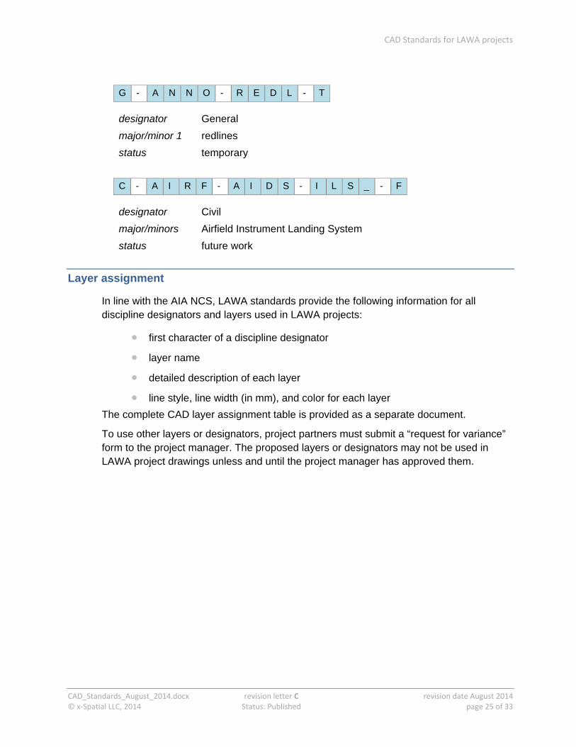
G - A N N O - R E D L - T
designator General
major/minor 1 redlines
status temporary
C - A I R F - A I D S - I L S _ - F
designator Civil
major/minors Airfield Instrument Landing System
status future work
Layer assignment
In line with the AIA NCS, LAWA standards provide the following information for all discipline designators and layers used in LAWA projects:
first character of a discipline designator
layer name
detailed description of each layer
line style, line width (in mm), and color for each layer
The complete CAD layer assignment table is provided as a separate document.
To use other layers or designators, project partners must submit a “request for variance” form to the project manager. The proposed layers or designators may not be used in LAWA project drawings unless and until the project manager has approved them.
CAD Standards for LAWA projects
CAD_Standards_August_2014.docx revision letter C revision date August 2014 © x‐Spatial LLC, 2014 Status: Published page 26 of 33
Symbols/Blocks
A block in AutoCAD is a group of graphical elements logically or locationally combined to a single entity. Examples of logical blocks are windows, doors, graphic scale keys, furniture, etc. Locational blocks are made of all objects within a specified area.
The primary requirement of any type of block is that each graphical object in a block belongs to a proper layer listed in the AIA NCS. This means that each element comprising the block will, when fully exploded, be layered in conformance with established AIA NCS and LAWA standards.

CAD Standards for LAWA projects
CAD_Standards_August_2014.docx revision letter C revision date August 2014 © x‐Spatial LLC, 2014 Status: Published page 27 of 33
Appendix A. File type codes per discipline
Disciplines (plus the discipline codes) are listed here in alphabetical order, for ease of reference.
Discipline designators for model files
Architectural (A) Landscape (L)
Civil (C) Mechanical (M)
Civil Works (W) Operations (O)
Electrical (E) Other disciplines
Equipment Plumbing (P)
Fire protection (F) Process
General (G) Resource (R)
Geotechnical (B) Structural (S)
Hazardous materials (H) Survey/Mapping (V)
Interiors (I) Telecommunications (T)
P R O J E C T 1 A - F P F
Architectural
Floor plan
Architectural (discipline A)
File type code Definition
3D Isometric 3D
AC Area Calculations/Occupancy Plan
CP Reflected Ceilinq Plan
DT Detail
EL Elevation
EP Enlarqed Plan
FP Floor Plan
LG Legend
OP Equipment Plan
RP Roof Plan
SC Section
SH Schedule
XD Existing/Demolition Plan
CAD Standards for LAWA projects
CAD_Standards_August_2014.docx revision letter C revision date August 2014 © x‐Spatial LLC, 2014 Status: Published page 28 of 33
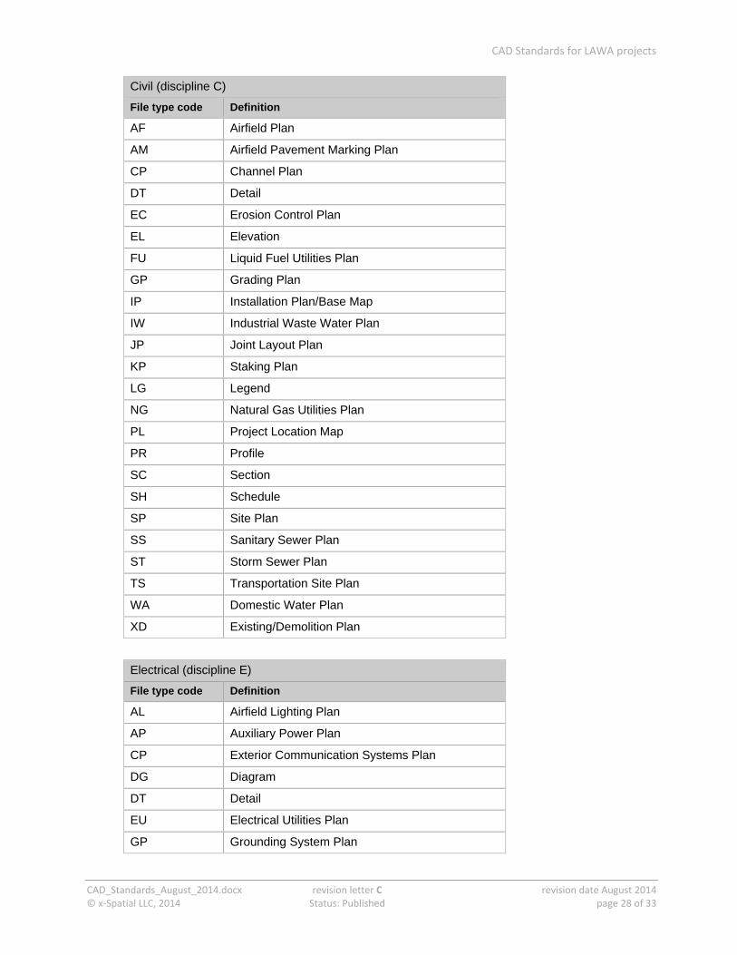
Civil (discipline C)
File type code Definition
AF Airfield Plan
AM Airfield Pavement Marking Plan
CP Channel Plan
DT Detail
EC Erosion Control Plan
EL Elevation
FU Liquid Fuel Utilities Plan
GP Grading Plan
IP Installation Plan/Base Map
IW Industrial Waste Water Plan
JP Joint Layout Plan
KP Staking Plan
LG Legend
NG Natural Gas Utilities Plan
PL Project Location Map
PR Profile
SC Section
SH Schedule
SP Site Plan
SS Sanitary Sewer Plan
ST Storm Sewer Plan
TS Transportation Site Plan
WA Domestic Water Plan
XD Existing/Demolition Plan
Electrical (discipline E)
File type code Definition
AL Airfield Lighting Plan
AP Auxiliary Power Plan
CP Exterior Communication Systems Plan
DG Diagram
DT Detail
EU Electrical Utilities Plan
GP Grounding System Plan
CAD Standards for LAWA projects
CAD_Standards_August_2014.docx revision letter C revision date August 2014 © x‐Spatial LLC, 2014 Status: Published page 29 of 33
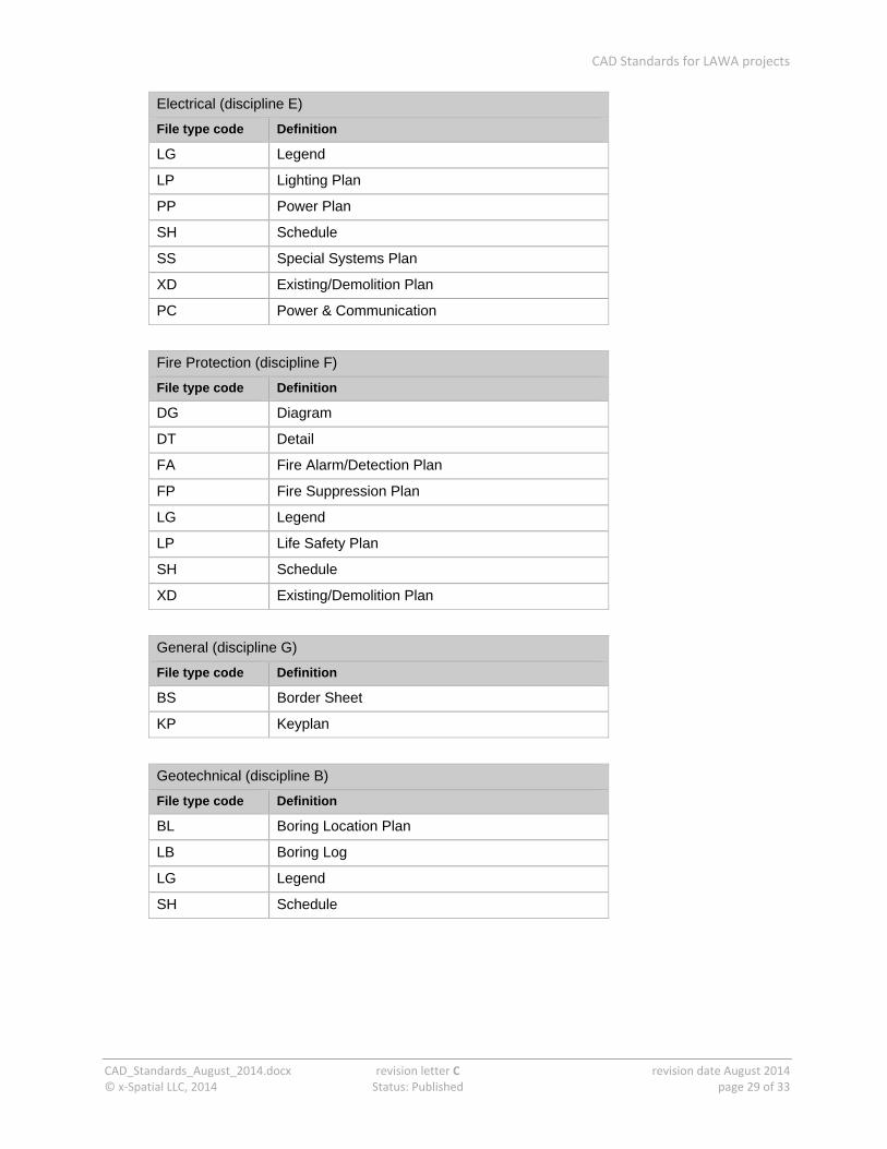
Electrical (discipline E)
File type code Definition
LG Legend
LP Lighting Plan
PP Power Plan
SH Schedule
SS Special Systems Plan
XD Existing/Demolition Plan
PC Power & Communication
Fire Protection (discipline F)
File type code Definition
DG Diagram
DT Detail
FA Fire Alarm/Detection Plan
FP Fire Suppression Plan
LG Legend
LP Life Safety Plan
SH Schedule
XD Existing/Demolition Plan
General (discipline G)
File type code Definition
BS Border Sheet
KP Keyplan
Geotechnical (discipline B)
File type code Definition
BL Boring Location Plan
LB Boring Log
LG Legend
SH Schedule
CAD Standards for LAWA projects
CAD_Standards_August_2014.docx revision letter C revision date August 2014 © x‐Spatial LLC, 2014 Status: Published page 30 of 33
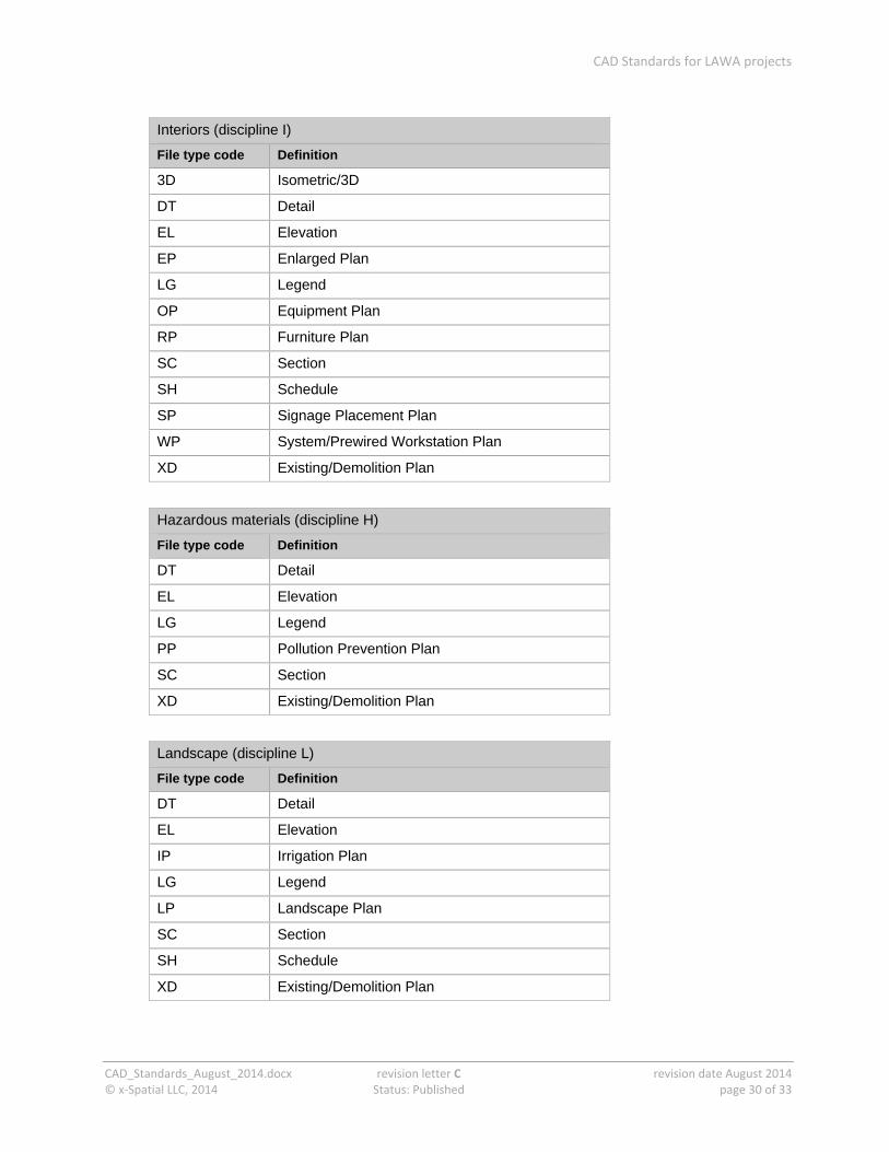
Interiors (discipline I)
File type code Definition
3D Isometric/3D
DT Detail
EL Elevation
EP Enlarged Plan
LG Legend
OP Equipment Plan
RP Furniture Plan
SC Section
SH Schedule
SP Signage Placement Plan
WP System/Prewired Workstation Plan
XD Existing/Demolition Plan
Hazardous materials (discipline H)
File type code Definition
DT Detail
EL Elevation
LG Legend
PP Pollution Prevention Plan
SC Section
XD Existing/Demolition Plan
Landscape (discipline L)
File type code Definition
DT Detail
EL Elevation
IP Irrigation Plan
LG Legend
LP Landscape Plan
SC Section
SH Schedule
XD Existing/Demolition Plan
CAD Standards for LAWA projects
CAD_Standards_August_2014.docx revision letter C revision date August 2014 © x‐Spatial LLC, 2014 Status: Published page 31 of 33
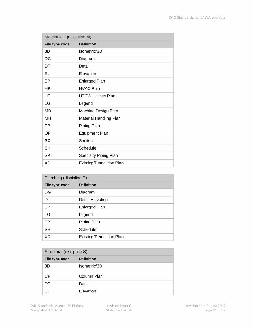
Mechanical (discipline M)
File type code Definition
3D Isometric/3D
DG Diagram
DT Detail
EL Elevation
EP Enlarged Plan
HP HVAC Plan
HT HTCW Utilities Plan
LG Legend
MD Machine Design Plan
MH Material Handling Plan
PP Piping Plan
QP Equipment Plan
SC Section
SH Schedule
SP Specialty Piping Plan
XD Existing/Demolition Plan
Plumbing (discipline P)
File type code Definition
DG Diaqram
DT Detail Elevation
EP Enlarqed Plan
LG Legend
PP Piping Plan
SH Schedule
XD Existing/Demolition Plan
Structural (discipline S)
File type code Definition
3D Isometric/3D
CP Column Plan
DT Detail
EL Elevation
CAD Standards for LAWA projects
CAD_Standards_August_2014.docx revision letter C revision date August 2014 © x‐Spatial LLC, 2014 Status: Published page 32 of 33
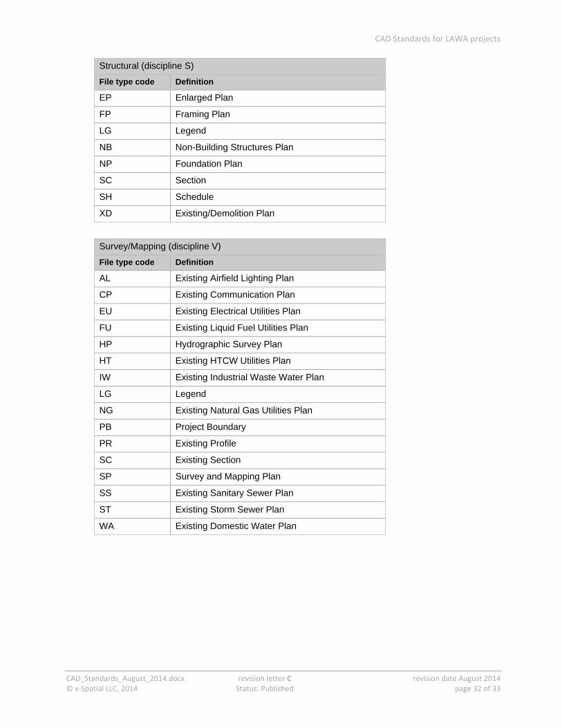
Structural (discipline S)
File type code Definition
EP Enlarged Plan
FP Framing Plan
LG Legend
NB Non-Building Structures Plan
NP Foundation Plan
SC Section
SH Schedule
XD Existing/Demolition Plan
Survey/Mapping (discipline V)
File type code Definition
AL Existing Airfield Lighting Plan
CP Existing Communication Plan
EU Existing Electrical Utilities Plan
FU Existing Liquid Fuel Utilities Plan
HP Hydrographic Survey Plan
HT Existing HTCW Utilities Plan
IW Existing Industrial Waste Water Plan
LG Legend
NG Existing Natural Gas Utilities Plan
PB Project Boundary
PR Existing Profile
SC Existing Section
SP Survey and Mapping Plan
SS Existing Sanitary Sewer Plan
ST Existing Storm Sewer Plan
WA Existing Domestic Water Plan

CAD Standards for LAWA projects
CAD_Standards_August_2014.docx revision letter C revision date August 2014 © x‐Spatial LLC, 2014 Status: Published page 33 of 33
Telecommunications (discipline T)
File type code Definition
DG Diagram
DT Detail
LG Legend
SH Schedule
TP Telephone/Data Plan
XD Existing/Demolition Plan