cadd package for analysis and design of underground rc tanks
TRANSCRIPT
CADD PACKAGE FOR ANALYSIS AND DESIGN OF
UNDERGROUND RC TANKS
A DISSERTATION
submitted in partial fulfilment of the requirements for the award of the degree
of MASTER OF ENGINEERING
in
CIVIL ENGINEERING WITH SPECIALIZATION IN
BUILDING SCIENCE AND TECHNOLOGY
Aec. No, — -- Vij' I,.
By 1l~t~..., ..
SURINDER KUMAR % . ..
DEPARTMENT OF CIVIL ENGINEERING UNIVERSITY OF ROORKEE
ROORKEE - 247 667 (INDIA)
JANUARY, 1996

CANDIDATE'S DECLARATION
I hereby declare that the work which is being presented in the
dissertation entitled "CADD PACKAGE FOR ANALYSIS AND DESIGN
OF UNDERGROUND RC TANKS" in partial fulfilment of the requirement
for the award of the degree of MASTER OF ENGINEERING with specialisation in
BUILDING SCIENCE AND TECHNOLOGY, University of Roorkee, Roorkee,
is an authentic record of my own work carried out from Aug. 1995 to January
1996, under the guidance of Dr. P.C. JAIN, Professor, Department of Civil
Engineering, University of Roorkee, Roorkee.
The matter embodied in this dissertation has not been submitted by me
for any other degree or diploma.
Dated: Jan. 3p , 1996 ( SURINDER KUMAR )
This is to certify that the above statement made by the candidate is
correct to the best of my knowledge and belief.
( Dr. P. JAIN) Professor
Civil Engineering Department University of Roorkee
Roorkee - 247 667 (India)
(i)

ACKNOWLEDGEMENT
It is with pervid sincerity that I owe my great debt and gratefulness
to Dr. P.C. JAIN, Professor, Department of Civil Engineering, University of
Roorkee, Roorkee for his invaluable suggestions, experts guidance,
incersant encouragement and constructive criticism althrough the persuance
of this work under his able and patient guidance without his perpetual
interest and sound counsel, this report would not have been brought out in
the defacto shape.
The assistance received through friends and fellow students,
especially those from R.S. KATHAIT and NAVEEN AGARWAL are thankfully
acknowledged.
Thanks are also due to NCF, Library and CAD Centre Staff especially
Mr. A.K. GAUR, Mr. M.S. RAWAT and Mr. VINOD KUMAR for their kind
cooperation and help.
Finally, I have no words to express thanks and gratitude to my parents
who have been my inspiration, through out this study.
Date : x.30,1906
Place: Roorkee (SURINDER KUMAR)

SYNOPSIS
CADD PACKAGE FOR ANALYSIS AND DESIGN OF
UNDERGROUND R.C. TANKS
Computers are widely used in Civil Engineering designs as they can
perform computational tasks of a magnitude far beyond the capability of any
human. The problems of analysis and design of underground reinforced
concrete tanks have been dealt in this dissertation. Primarily, the
analysis and design of reinforced concrete underground tanks involve
tedious calculations and numerous design charts and their interpolation.
Any careless human error may result in fatal error. Therefore, a computer
aided design would appear to be necessary.
Underground tanks are used in water purification, sewage treatment and
for storage of water reserve for fire fighting etc. The sides have been
designed for both the cases, when tank is empty with earth pressure acting
from out side and tank full with no earthfill surrounding it.
A software 'RCTANK' is developed for design of various elements of
underground tanks under different end conditions of wall with varying site
conditions. Drafting of rectangular tank has also been done for sectional
views. Static and dynamic pressures both can be dealt, with choice resting
on user. Software offers great deal of flexibility in structural design and

complies with relevant codal provisons, i.e. IS: 456-1978, IS: 1893-1984,
IS: 3370-Part-I, II and IV.
The package has been developed in FORTRAN 77 language using FORTRAN 77
and PLOT88 compilers for use on any IBM compatible computer. The package is
made complete and effective by including drafting part which gives
sectional views of elevation and plan of rectangular tank.
The working of the software package has been illustrated by solving
few design problems.
(iv)
LIST OF FIGURES Fig. No. Title Page No.
2.1 Variations of Earth & Water Pressure on 14 Tank Wall.
2.2 Deformation of Circular Tank Having Flexible 14 joint at Base.
2.3 Deflection of Wall & Variations of Ring Tension 14
2.4 Variation of Bending Moment. 14
2.5 Load Distribution Curves. 14
2.6 Carpenter's Coefficients. 15
2.7 Approximate Demarcation between Hoop &
15 Cantilever Action.
2.8 Variations of Loading on Wall. 24
2.9 Horizontal Forces. 24
2.10 Pressure Variation on Sloping portion. 25
2.11 Pyramidal Bottom. 25
3.1 Surface Zones. 36
4.1 Partial Contraction Joint. 41
4.2 Complete Contraction Joint. 41
4.3 Construction Joint. 41
4.4 Expansion Joint. 42
4.5 Sliding Joint. 42
4.6 Temporary Open Joints. 42
4.7 Plan Showing Joints. 43
5.1 Hogging Moment. 50
5.2 Sagging Moment. 50
6.1 Flow Chart of COMBIN.FOR. 69
6.2 FLow Chart of Subroutine CALCULN. 71
6.3 Flow Chart of Subroutine CIRCULAR. 75
6.4 Flow Chart of DRAFTI.FOR. 79
6.5 Flow Chart of DRAFT2.FOR. 80
(v)

LIST OF TABLES
Table No. Title Page No. 2.1 Reissner's Value of Restraint Moment. 16
2.2 Reissner's Value for Ring Tension. 16
2.3 Carpenter's Value of Coefficients F and K. 16 2.4 Coefficients for Hoop Tension in Cylinderical 17
wall Fixed at Base. 2.5 Coefficients for Bending Moment in Cylinderical 17
Wall Fixed at Base. 2.6 Coefficients for Hoop Tension in Cylinderical 18
Wall Hinged at Base. 2.7 Coefficients for Bending Moment in Cylinderical 18
wall hinged at base 2.8 Moment Coefficients for Wall Panel, Top Free 26
and Bottom Fixed. 2.9 Moment Coefficients for Wall Panel, Top Free 28
and Bottom Hinged. 2.10 Moment Coefficients for Wall Panel, Top and 29
Bottom Hinged. 3.1 Permissible Concrete Stresses in Calculations 37
Relating to Resistance to Cracking. 3.2 Permissible Concrete Stresses for Strength 37
Calculations. 3.3 Permissible Stresses in Steel for Strength 38
Calculation.
6.1 List of Devices Supported by Plot88. 81
C" )

LIST OF NOTATIONS
Ash = Area of steel in vertical direction
BFT = Bearing stress in soil
D = Diameter of tank
FH = Free board
GAMA,a = Unit weight of soil
H = Height of tank
Hi = Depth of tank in soil
Ka = Coefficient of lateral active earth pressure
L = Length of tank
Spagi(i)=Spacing of horizontal reinforcement at inner face
Spago(i) = Spacing of horizontal reinforcement at outer face
Spagvi(i)=Spacing of vertical reinforcement at inner face
Spagvo(i) =Spacing of vertical reinforcement at outer face
T = Thickness of wall
W = Unit weight of water
WT = Water table position below ground level
ZSS = Code for square/Rectangular tank
= Angle of internal friction of soil
= Angle of friction between wall and earthfill

CONTENTS S.No. Page No.
CANDIDATE'S DECLARATION (i)
ACKNOWLEDGEMENT (ii)
SYNOPSIS (iii)
LIST OF FIGURES (v)
LIST OF TABLES (vi)
LIST OF NOTATIONS (vii)
1. INTRODUCTION —, I
1.1 General 1
1.2 R.C. Tanks 2
1.2.1 General 2
1.2.2 Underground tanks 3
1.3 Objective of Study 4
1.4 Organisation of Thesis 6
2. ANALYSIS OF UNDERGROUND TANKS 8
2.1 General 8
2.2 Analysis of Circular Tanks 9
2.2.1 Circular tank with flexible joint at base 9
2.2.2 Circular tank with rigid joint at base 9
2.3 Analysis of Rectangular Tanks 19
2.4 Tanks with flat base slab 21
2.5 Tanks with pyramidical or conical floors 22
2.5.1 Tanks in hard dry soil 22
2.5.2 Tanks in soft wet soil 22

3. CODAL PROVISIONS 30
3.1 Imperviousness of Concrete 30
3.2 Control of Cracking 30
3.3 Methods of Design 31
3.3.1 Working stress method 31
3.3.2 Limit state method 32
.3.4 Minimum Reinforcement 34
3.5 Minimum Cover 35
4. JOINTS IN WATER TANKS 39
4.1 Movement joints 39
4.1.1 Contraction joints 39
4.1.2 Expansion joints 39
4.1.3 Sliding joints 39
4.2 Construction joints 40
4.3 Temporary joints 40
5. DESIGN ASPECT OF UNDERGROUND TANKS 44
5.1 Design of walls of circular tank 44
5.2 Design of walls of rectangular tank 47
5.3 Design of base slab 51
5.3.1 Design of sloping base slab 51
5.4 Tank design as a cantilever retaining wall 53
6. SOFTWARE ASPECTS 56 6.1 General 56 6.2 Software for anlaysis, design and drafting 58
6.2.1 Input to main program 58 6.2.2 Description of subroutines 59

6.2.3 Drafting of designed section 67 6.3 User interface 68
7. TEST EXAMPLES 82 S. CONCLUDING REMARKS 117
8.1 Conclusions 117 8.2 Scope of further work 118 REFERENCES

CHAPTER - 1
INTRODUCTION
1.1 GENERAL
In an age of major technical advancement, there can only be few
innovations with such far reaching potential effects as the development of
digital computer. In span of less than 40 years the computer has emerged
from laboratory to become an extremely powerful tool touching the everyday
life.
Initially, the use of computer was limited to field of Science and
Technology, but more or less, it is now going to help every part of human
knowledge. As far as uses of computer in Civil Engineering works is
concerned, they are now gaining maturity in developed countries but is
still in its infancy in developing countries like India.
Use of computer in Civil Engineering works is mainly concerned with
the analysis and design of structures, but its multidirectional capability
like ability to store and to sort an immense amount of information and
carrying out most complex computations, showing almost instantaneously
numerical and graphical results, resulted its use in nearly every field of
Civil Engineering.

The designs of reinforced concrete liquid retaining structures involve
many tedious calculations and numerous design charts. Frequently some
careless human errors, which may be fatal to the design, may be introduced
in calculations or in interpolation of design charts.
Some time numerical results given by computer may be confusing to user
so graphical representation of analysis and design (drafting) is also
required.
In view of this computer aided design and drafting (CADD), software
package would appear to be necessary. The capability to take different
options using computers will also relieve design engineer from tiring work
associated with routine calculations leaving him plenty of time to take
other important decisions.
Design and drafting of underground RC tanks has been dealt with in
this dissertation under various end conditions of tank wall and site
conditions. Design has been done for extreme condition of tank empty and
tank full cases.
1.2 R.C. TANKS : A Brief Introduction
1.2.1 General
RC tanks are used for storage of large volume of potable, sanitation
and industrial water, petroleum products, industrial acids and as sewage
oxidation and settling ponds. They are also used in small hydroelectric
power plants as settling and forebay tanks.
2

Based on shape, underground tank can mainly be classified as circular
and rectangular tanks having flat or sloping base slab. Circular tanks are
more advantageous for large storage because for a given volume it has less
surface area than that of rectangular tanks. Furthermore the cylinderical
wall can be made thinner because it is mainly subjected to hoop tension
only, whereas rectangular tank wall undergoes both tension and bending both
in horizontal and vertical direction. Circular tanks are uneconomical for
small storage, as cost of shuttering increases due to curved shuttering
requirement, whereas analysis of large rectangular tank is more time
consuming and it is difficult to make them impervious due to corners.
Circular tanks can be made impervious easily.
1.2.2 Underground Tanks
Generally in multistoreyed buildings, complete storage of water can
not be provided on roofs and due to non availability of land underground
tanks are preferred. Wholly or partly, RC underground tanks are used on
water purification or sewage treatment plants, settling and forebay tanks
in case of small hydro-electric power plants, oil storage in petrol pumps
etc.
Tile side of tank has to resist earth pressure acting from outside and
water pressure from inside. The worst case arises when tank is empty and
soil around it is charged with water. A worse case also occurs when tank is
full and earth around it shrinks away from walls. This eventually, however
is safeguarded at time of construction by filling the space around with
3
well compacted granular material so that it acts as support, but as per IS:
3370 (Part-I)-1965, relief from external earth pressure should not be
relied upon unless sure about it.
Tanks are tested in some cases for leakage through walls before
filling earth around the walls. In such circumstances, the tanks are
designed for full liquid pressure acting outward.
For earth pressure calculation, level of subsoil water table is taken
into consideration, if it rises above the bottom of, tank, lower part of
fill remains submerged and upper part saturated. The submerged soil exerts
pressure with density of earth reduced due to buoyancy plus full water
pressure.
The base of underground tanks is usually made monolithic with wall for
small storage whereas in case of large storage, joints at base are
provided. At the junction of base slab with side walls, waterproof joint
with copper strip embedded on both sides should be provided. If the subsoil
water is likely to rise above base level, then there may be an uplift
pressure on base tending to lift it when tank is empty. Then base slab is
designed for uplift pressure with projection, for safety against uplift.
1.3 OBJECTIVE OF STUDY
In this dissertation work, a user interactive computer aided design
and drafting (CADD) package 'RCTANK' has been developed on Tata Elexi-3220
0

main frame system installed at new computational facility of University of
Roorkee using FORTRAN language. Drafting of Rectangular tanks has been done
using PLOT88.
This package has options for type of tank (circular or rectangular)
with different• end conditions. For design of circular tank, dissertation
work of Anuj Kumar Jain [8] has been taken and combined with rectangular.
tank program so as to form a complete package for design of underground
tanks.
This CADD packaze is developed to design tank with varying site
conditions and different end conditions with different types of base slabs.
For rectangular tanks, various end conditions are as follows:-
1. Top free & bottom fixed
2. Top free & bottom hinged
3. Top and bottom hinged.
For top free, bottom fixed case if L/H ratio exceeds 3.0, -then wall is
designed like cantilever retaining wall. Subsequently after design,
drawings (Drafting) are prepared by program files named `DRAFTI.FOR' for
sectional elevation and 'DRAFT2.FOR' for sectional plan of tank. For
cantilever, retaining wall case, sectional elevation is prepared by program
file 'DRAFT3.FOR'.
5

Circular tanks have been designed for following end conditions:
1. Top free bottom fixed
2. Hinged at base free at top
For top free bottom fixed case if diameter exceeds 12m,then it is also
designed like cantilever retaining wall. Design of these tanks has been
done as per Indian Standard code method using coefficients given in IS:
3370 (Part IV)-1969. The static and dynamic pressure both can be dealt,
with choice resting on user. Software offers great degree of flexibility to
user and has been compiled with relevant codal provisions i.e. IS: 456-
1978, IS: 1883-1994 and IS: 3370 (Part I, II, IV).
Illustration of above software package has been made by solving few
design problems.
1.4 ORGANISATION OF THESIS
The work carried out is divided in following seven chapters.
Chapter-1. deals with general . introduction to underground tanks, necessity
of CADD package and objective of present study.
Chapter-2. deals with analysis and structural design of RC underground
tanks.
Chapter-3. deals with codal provisions regarding design of underground
tanks. It also lists changes in first revision of IS: 3370
(Part I and Part II) draft.
0

Chapter-4. deals with various joints used in underground tanks.
Chapter-5. deals with design steps involved in rectangular and circular
tanks.
Chapter-6. deals with software and various subroutines developed.
Chapter-7. gives output of some test problems including drawings.
Chapter-8. contains concluding remarks.
7

CHAPTER 2
ANALYSIS OF UNDERGROUND TANKS
2.1 GENERAL
Underground tanks in addition to self weight are subjected to
following forces.
(i) Water pressure acting outward
(ii) Earth pressure acting inward
(iii) Weight of water acting downward
(iv) Uplift pressure
Tank walls are designed for two conditions
(1) Tank empty with full earth pressure.
(2) Tank full with no earth pressure
First condition arises when tank is empty and second condition arises
when surrounding earth shrinks or tank is checked for leakage.
In case earthfill is well compacted with granular material then water
pressure may be taken as half of. the actual water pressure with no earth
pressure. But in most of the cases underground tanks are checked for
leakage so it is essential to design the tank for full water pressure.
(Fig.2.1).
t

The base slab of tank should be checked for uplift pressure, the worst
condition arises when tank is empty with water table rising above base
slab. The projection of base slab is decided on the basis of the fact that
weight of soil on projected slab plus self weight of tank should be more
than uplift force on the base slab.
2.2 ANALYSIS OF CIRCULAR TANKS
2.2.1 Circular Tank with flexible Joint at base
For tanks with no earth pressure condition, water pressure acting
outward tends to increase the diameter, linearly varying from top to bottom
as shown in Fig.2.2. This causes hoop tension in walls, whereas for empty
tank case hoop compression is developed.
Hoop Tension = wHD/2
Hoop Compression = iH 1 D/2 Ka
Where w & x = wt density of liquid & earth respectively
H & H 1 = height of tank & earthfill respectively.
D = diameter of tank
2.2.2 Circular Tank with rigid joint at base
When joint at base is rigid, no horizontal movement of the wall at
base is possible. Deflected shape of wall is shown in Fig.2.3. Upper part
of wall will have hoop tension while lower portion behave like cantilever.
Various methods of analysis are as follows
1) Reissner's method [2]
2) Carpenter's Simplified Method [2]
3) Approximate Method [11]
4) IS Code Method 15
5) Analytical Method [ 161
(1) Reissner's Method
As per Dr.Reissner pressure is counteracted by the combined ring and
cantilever action i.e. pressure at any depth of wall is composed of
pr(Portion of load carried by rings) and pc( remaining load resisted by
cantilevers)
i.e P X r c
A curve dividing the triangular load into two portions called "load
distribution line" shown in Fig.2.3 indicates that at X = H load is
totally resisted by cantilever action (pc = p at X=H). In upper portion
of wall pc assumes negative value, shown by horizontal shading in fig. 2.3.
According to this theory all tanks with same value of `K' have
similar load distribution curves. Factor `K' is defined by expression given
below.
K= 12H4 48 H4 (D~2 T2
10

Where H is height, T is thickness and D is diameter of tank.
Depending upon the value of `K' various load distribution curves,
tables for restraint moment (M f) and maximum ring tension or compression
are given in Fig.2.5 and Table 2.1 & 2.2 for . both uniform and triangular
section.
(2) Carpenter's Simplified Method
Carpenter, simplified Dr.Reissner's method and gave the values of
maximum cantilever bending moment and maximum hoop tension and its position
in terms of following expressions.
(a) Position of maximum hoop tension L = KH
(b) Maximum hoop tension = T = (1-K)pD/2
(c) Restrain moment = F p H2
where, p = wH. The values of coefficients K & F depends upon H/D and
H/T Ratios and can be taken from Fig.2.6 or Table 2.3.
(3) Approximate Method
This method is followed when Reissner's or carpenter's tables are
not available. In approximate method, it is assumed that cantilever action
will take place for a height W.
Where
h = H/3 or 1 m [whichever is greater] for 6~H2/DTI 12.
h = H/4 or lm [whichever is greater] for 12~H2DT~30.
11

Fig.2.7(a) & (b). Above this height `h' there is hoop action,
maximum hoop tension per meter height = w(H-h)D/2
(4) IS Code Method
IS:3370(Part IV)-1967 gives design tables for moment and hoop
tension in circular tanks for various conditions of joints and loading for
Poisson's ratio µ=0.2 for concrete. We have case of triangular loading with
base rigid and base hinged. The Table (2.4) to Table (2.7) give
coefficients for various H2/DT ratio and base conditions.
The hoop tension and moment in wall can be directly calculated from
these coefficients using following expressions.
Hoop tension = coefficient * wHD/2 N/m
Bending moment = coefficient * wH3 N-m
Shear force at base = coefficient * wH2 N-m.
(5) Analytical Method
At any section at depth `x' below the top, the deformation yr due to
hoop stress will be equal to displacement yc due to horizontal shear. The
sum of loads transferred due to cantilever action and ring action is
evidently equal to intensity of water pressure at that section. i.e.
pc +pr =w.x (i)
12

I = moment of Inertia at depth `x'
T = thickness of wall
For compatibility yc = yr = y (say)
Tensile strain due to ring action = pr D/2TE
Change in radius due to pr yr = pr D2/4TE
or pr = 4T yrE/D2 = 4TE y/D2
From simple theory of bending we have
4 y 4 B. M = El d
and load intensity pc = EI d = El 4
Ldx2J
dx dx
d4y From (i) w.x - 4 pr = El dx
which on simplification gives (putting T/ID2 = a4)
4 +4a4y=l dx
The solution of above differential equation is y = w x /(4EI a4) + e«'x (A sin ax + B cos ax)
+ e-ax (C sin ax + D cos ax)
The value of constant A, B, C and D can be evaluated by applying
boundry conditions at ends of wall.Hence bending moment and hoop tension
variation can be calculated.
13
Cirsu/a! rgr~ks 'Zocrd Des r~but,on ' Curve,T , -e•,- a n I-
~Wqr
1 I I i i
I ~--,initial posJlon H I I
deformed ~osi t ion '
Fig..2.2Defcrrnation of circular tank having flexible joint at base.
Fig.2.1 Variation of earth & water
pr.essurp on tank wall.
a>xdthj/r/bvfpn Line
X rr.•~.r. pas~twe /';o~~~ent
----P.Y-- - ~--I ~~rnenf- Cw►~e
Fig. 2.3: Deflecti•~n of wall Fi.g.2.4 : Variation of hendin momen, variation of rin? tension.
I S 3• G
8 s
wYP toed,
}11 7 2.5 Load distr. i-hution curves.
14

!iIllIIiII
()P±'
C ':V(S
'02- u-i i i 1rrrrl i i ii rut i i ITT f i i ITTITi
L -0
I I I I I t___J 0 .3 •# 5
iahc, D
Ci rcjja
R/in 7 (K)p, p-H
L
r Ltd
.75
0
C 1-0 3-c
.raj/O /T D
Fig.2.6Carflefltets Coefficients
-
LOAD T4,KEN BY I
HOOP ACTION
Hh
C) 1'0,
. _
L.L0CD nE y W H
(--(At4 rILvE CTIQr
(a) Fl 2.7pProxIIflte demarcation b-teen hoop 5< cant ever Action
15
s
D

TABLE 2 . 1 REISSNER'S VALUE OF RESTRAINT MOMENT Mf (p •= wH)
K { Rectangular wall section Triangular wall section
0 0'167 pH' x'167 pH' 10 0110 pH2 0'140 pH'
100 00582 pH' 00707 pH 2 1000 0024 pH' 0 026 pH'
10000 0.0085 pH' 0009 pH' 0c 0 0
TABLE 2 .2 REISSNER'S VALUE FOR RING TENSION (p='wH)
Rectangular wall section Triangular wall section K
Max. tension Height from Max. tension Height from base base
0 0 - — —
10 0'13 p( 2 ) 1'0 H O'09p( 2 065 H - 100 0-27p(' ) 1'0 H 031 p` ) 0.58 H'
1000 0'47 p( ) 0.47 H 0'52p( 2 ) 044 I3 10000 067 p ( ) 0 31 H 0'70 p( -P ) 030 H
0 1 Op(~ } 0
TABLE 2.3 CARPENTER'S VALUES OF COEFFICIENTS F AND K
Factor F -- — K
H 10 20 30 44 If 20 30 40 T
0046 0.028 0.022 0.015 — 0.50 1 045 0 40 02
03 G032 0019 ; 0.014 0 010 0.55 043 i 038 013
04 0.024 0014 0.010 0007 050 019 0'35 0.30
05 0 020 0-012 ' 0 009 0'006 045 037 0 32 0.27 v 10. 0012 0.006 0'C05 0.0031. 037 0.30 , 0'24 0.21
2.0 t
0 005 0011 0 002 0 0021 i
028 c 22 019 0.16
40 0 00> 0'G3 0002 '001 0.27 0.20 017 014
16
Ii'
TABLE 2.4 Coefficients for hoop tension in cylindrical
wall hinged at base
T - Cocll•icicnt X w1/fl kg/rn 1 1
-{lkwH-4 { CotrrlcllnTl AT PONT
o•orr o• 11r o z tr 0-311 (1) (2) (3) (4) (5) 0.4 +0.474 +0.440 +0.395 +0.352 0.8 +0. 423 +0402 +0 381 -4-0.758 1.2 -X 0.350 +0.355 +0.361 +0.362 1.6 +0.271 +0.303 4-0.341 +0.369 2.0 +0-205 +0.260 +0.321 +0.373
30 -4-0.074 +0.179 +0.281 +0.375 4.0 -+0 017 +0.137 +0.253 +0.367 5.0 -0008 +01-14 +0.235 +0.356 6.0 -0-0)1 +0.103 +0.223 +0.343 8.0 -0.015 +0.096 +0.208 +0.324
10.0 -0008 -} 0 095 +0.200 +0.311 12.0 -0.002 +0097 +0.197 -4-0-302 14.0 0000 -1-0098 +0)97 +0.299 16.0 +0.002 -4-0)00 +0.198 +0.279
NOrs I - w - Dcnttty of the liquid. No-ri 2 -- Pcnitivc sign indicate tcflhion.
0. 411 o- 5H 0.6/1 0 711 0.8H 0.9/1 (6) (7) (8) (9) (10) (II)
+0.308 +0.264 +0.215 -+0165 +0.111 +0.057 +0- 330 +0-297 +0.249 +0-202 +0.145 +0 076 +0.358 +0.342 +0.309 -4.0 256 +0.186 +0.098 +0.385 -4.0.385 +0.362 -4.0.314 +0.233 +0.124 +0.411 -4-0.434 +0.419 -4-0.369 +0.280 +0.151 +0.4-49 +0.506 +0.519 +0.479 +0.375 +0.210 +0.469 +0.543 +0.579 +0 553 +0.447 +0.256 +0.469 +0.562 +0.617 +0 606 +0.503 +0.294 +0.463 4-0.566 +0.639 +0 643 +0.547 +0.327 +0.443 +0.564 +0.661 +0.697 +0.621 +0.386 t ^ +28 +J 55^ +0-666 U /3U 0-678 +0-433
::/ +0.541 +0.664 +0.750 4-0.720 -4-0.477 +0.408 -}-0.531 +0.659 -4-0-76) -1-0.752 -4•0.513
-0 ::" . ; SZl +0.650 +0.764 +0.776 +0.536
TABLE 2.5 ..Coefficients for bending moment in cylindrical wall hinged at base
M
Iun cnt - Cociltc1cnl X ( will' + ANr ) k ro rn F{
1 v wH
C-oiritci 1 -ill AT P01NT
lr 02/1 3 . 3)1 0 - 4)1 0 5/1 0 .611 0.711
(3) (4) (5) (u) (7 l (8) 420 -00012 +00)51 +00230 +00301 +00348 -+00357 019 t000 4 --00133 -4-002(17 -~i1027I }003)9 +00329 (ii 6 ( 0 005 8 -+0 01 I I +0-0177 i 0-023 7 4-0.02(11) -4-0.029 6 012 -100044 i0009I -40.014S 400)35 +00236 +00255 009 ♦00033 -f )0073 +00114 +00)58 -{0019'9 +0.02)9
(04 +(11)018 +0.0040 +00063 }00092 -+(1.0)27 }00)52 nH)I 4 001)07 1+10016 -+-0.0033 -40.0057 -}00003 -4-0109 MtO 0 •1-0 (N30 I -1-0.000 6 +0 001 6 - 0 (x1)1 -I 0-01)5 7 •1.0.060 0 M14)(7 4(4(XX)0 ,I)0002 1000011 4))Ix)19 +0((039 -4-004)02 KI0 0000O -00M12 -400(110 •100 07 (001420 1(11x1'50
c -I)0 U 04 MI t1 --0-000 2 -0-000) -{ U 0007 4 0 001 I -{• 0 11+1-7 `, " ~) I) 0 (kx) U --0 (XX) I - 0 000 2 0-0(Y) 0 I 0-0(X) 5 i-0001 7 ra).i 1)000O -(4lc~U1 -(l(x)0I -00(M)1 001300 400012 tA))) (4)K)n(4 1) (XX) 0 -(3 04)0 1 -0 UL(() 2 -1) 01)0 4 1 n OtU II
- I)fnrity u( i) c Ii-1uitl.
P n~ilivr ttg u (tc ntci Icnhion on Ills ouilt.)c
17
II
0- (I) 0.4 A0tt 08 -100 1.2 + 0 C 10 4 0 O 20 4-0C 3.0 -+0 40 -+rlt 5'0 0t 60 n0 HO (1t
t t1 0 o t 12-0 l
140 1)t 160 t)t
NoTa2-
0 .811 0.9// 1 .011
(9) (10) (II)
-4-0 031 2 +0.019 7 0 +00.92 10.0187 0 +1)0263 -}-0.017 I 0 +0 11232 +0-0155 0 -} 0.1)20 5 1 0.014 5 0
1-01)153 -10.011 l 0 01 18 +0000 2 0
400004 10.0078 0 )0007(4 -4t)6068 0 ill ttt5 -400(454 0
U ((((4 1 4-0 004 5 0 0(x))? 4-0 003 9 0
t t) 1 x) 2 i, 1000 3 3 0 (,t)u; 2 11)0029 0

TABLE 2.6 Coefficients for hoop t•nnsi in cylindrical wall fixed at base
T - C.oc10cicnt x m11R kg/m I
f II
-
1 '
10 _~- CocrrrtCSINTS AT PoluT
of -- -- t)0// 0- 1f 0.2/( 0-3H 0.411 0.511 V 061! 0.711 0.8H 0.9/!
(I) (2) (3) (4) (5) (6) (7) (8) (9) (10) (II)
0.4 +0-149 +0-134 4-0.120 +0.101 +0-682 +0-066 +0049 1-0,029 +0014 +0-004 0-8 +0263 +0.239 +0.215 +0-109 +0.160 +0.130 +0.096 -0.063 +0.034 +0.010 1:2 +0283 +0271 +0254 +0.234 +0.209 +0.180 +0.142 +0.099 +0.054 +0.016 1.6 +0265 -4-0.268 +0-268 +0.266 -4.0.250 +0.226 +0.105 +0.134 +0-075 +0.023 2.0 +0.234 +0 251 +0.273 +0.285 +0.285 +0.274 +0.232 +0.172 +0.104 +0.031
3-0 +0.13. 11 +0.203 +0.267 +0.322 +0.357 +0.362 4-0.330 +0.262 +0.157 +0.052 4.0 +0067 +0.1&4 +0.256 +0- 339 +0- 4-03 +0.429 +0.409 +0.334 +0.210 +0.073 5.0 +0.025 4-0137 +0.245 +0.346 +0.428 +0.477 +0.469 +0.398 }0.259 +0.092 6.0 +0.018 +0.119 . +0.234 +0.344 +0.441 +0.504 +0.5)4 +0447 +0.301 +0.112 80 -0.001 +0.10+ +0.218 +0.335 +0.4.43 +0.534 +0.575 -4-0.530 +0.381 +0.151
10.0 -0001 +0.098 +0-208 +0.329 +0.437 +0.542 +0.608 +0.589 +0.440 +0.179 120 -0 005 4-0-007 +0.202 +0.312 +0.429 ' 0-43 ±0.628 +0.633 +0.494 ±0.211 140 -0.002 +0.098 +0-200 +0.306 +0.420 i-.. - - 9 +0.639 +0.666 +0.541 +0-241 16.0 0.000 +0.099 +0-199 +0.304 +0.412 +0.511 +0-641 +0.687 +0.382 +0.265
Nora I - w- Deruity of the liquid. Nor* 2 - Poeitivc sign indiuty tension.
TABLE 2.7 Coefficients for bending moment in cylindrical wall fixed at base
,)mcn(--Coc(jicicntxtvH 3 kgmlrn 1 I h = -
111 COC/ ULKT1 AT POWT
151 0111 0 211 0311 041- 0511 0611 07t1 0811 0916 H
(I) (2) (3) (4) (5) (6) (7) (8) (9) (10) (11)
04 +0 0005 -1-00(114 +0.002) +0.0007 -0.0042 -0-0150 -0.0302 -0.0529 -0.0816 -0.1205 0.8 +11.001 1 +0-0031 +0.0063 +0.0080 +0.0070 +0-0023 -0.0068 --0.0024 -0.0465 -0.0795 1.2 +0.0012 +0.0042 +Q - 0077 +0.0103 +0-01)2 +0.0090 +0.0022 -0.0108 -0.0311 -0.0602 1.6 +0 00) I 1-0.0041 +0-0075 +0.0107 +0.0121 +0.0) 1 I +0.0058 -0.0051 -0-0232 -0.0505 2.0 +0 0010 ±0.0035 -4-0-00k8 +0.0099 +0.0120 +0.0115 +0.00)5- --0.0021 -0.0185 -0.0436
3.0 +00006 +0.0024 +0.0047 +0.0071 +0.0094 +0.0097. +0-0077 +0.00)2 -0-0119 --0.0333 4-0 +0.0003 +0 0015 +00028 +0.0047 +0.0066 +0.0077 +0.0069 +0.0023 -0.0000 -0.0268 5-)) +0 (002 +n 000)) -4-000)6 4-0 0029 +0.00.16 4.0-0059 +0 0051 1 0.00211 -0.0050 -0.0222 0-0 -4-0.000) -} 0 1-00:1 4-0-0008 -4 0 0019 +0.0011 -4 0-OOir, +0 vu',l 4-0.0+179 - C1 ((14I -0-0)07 8-)) U th0(0() •I.0.0001 -1-0.0002 1-0.0008 -4 0 00)6 -+-0.00214 -4-0-0030 -4-0-0029 -0.0022 -0.0146
►n n (1.0000 n 0000 +1) 0001 -1 0-000-) +0-0007 -t-0-00)9 -1-00029 -1.0 ((l?8 -0 1X)12 -0.0122 I/O 0 (XI(k) --C) 1-(007) -}-(1 0(3(11 -1(1 0002 -4.0 (x.103 +0-0<1)3 -}-(l CX121 -4)) ) )'°21 --11 (N1(15 -0-0)04 hit 11 (Miry) I) 1x1111) 1) f)01N) O i11NN) -1 1) ISX)1 1 0 IXX)Il .I f)•INV)fl ill IM0' I Il IIINII •- 11.1)0 )0
16.0 a Ax)) (I u>Nt() --0-04k)) --0-0(X)? -0•(xxl) +0-(x)i01 i 01x1I) •i 0-Wl'l -4-0-0(.)0) --0-0079
N OTL I - In- 1)int>ly of the lih-nll. NOT 2 -- r' .c n ~RdKxcts t-c\-, >n un the c~ut.i~0-

2.3 ANALYSIS OF RECTANGULAR TANKS
The walls of a rectangular tank are subjected to bending moment both
in the horizontal as well as in vertical direction. The magnitude of moment
will depend upon several factors such as length, breadth & height of tank,
and the condition of support of wall at top and bottom edges. If the length
of wall is more in comparison to its height the moments will be mainly in
the vertical direction i.e., the panel will bend as a cantilever. However,
if height is large in comparison to length, the moment will mainly be in
the horizontal direction and the panel will bend like a slab supported on
edges. In addition to these moments, the walls are also subjected to direct
pull exerted by water pressure.
Following are the method of analysis:
I. Approximate Method liii
2. I.S. Code Method 151
1. Approximate Method
Rectangular tanks under this head are classified as,
(a) Tank with ratio of length to breadth less than two
(b) Tanks with ratio of length to breadth greater than two.
(a) L/B Ratio less than 2
In this case tank walls are designed as continuous frame subjected
to a triangular load. This behaviour or bending is considered to take
place from top to a height h= H/4 or Im above the base whichever is
greater. For bottom height `h', bending is assumed in vertical plane as
cantilever, subjected to triangular load, having zero intensity at D and wII
at the base, as shown in Fig. 2.8.
19

For horizontal bending the maximum force per unit height, at D is
taken equal to p=w(H-h) per metre run. The panels are assumed fixed at the
side and fixing end moments are pL2/12 & pB2/12 for long and short span
respectively. (Fig.2.9) Moment distribution can be carried out and moment
2 Mf at corners are found out. Therefore moments at mid span are P -M f &
IpB
LJ -M f for long and short wall respectively.
Bottom portion of height h of each panel is designed as cantilever
like circular tank case.
Direct tension on long walls = PL = w(H-h)B/2
Direct tension on short walls = PB = w(H-h)L/2
(b) L/B Ratio greater than 2
In this case long wall is assumed to bend like cantilever vertically
fixed at base and subjected to triangular load. The short wall is assumed
to bend horizontally, supported on long wall, for the portion from top to
the point D (Fig. 2.8) . The load intensity for such a bending is taken as
p = w(H-h). In short wall the bottom portion upto height h= H or I m which
ever is greater is designed as cantilever like previous case.
Thus, for long wall, maximum B.M. of the base, per unit length of
wH3 wall is
20

For short wall, the maximum bending moment at level D, at ends and
centre may be taken as w(H-h)B2/16 and maximum cantilever B.M. for short
wall is equal to wHh2/6. Direct tensions on long wall is given by PL = w(H-
h) B/2.
The long wall behave like cantilever, and hence they do not transfer
any water load to short wall in the form of pull.
2. IS Code Method
IS Code IS:3370(Part IV) 1967 has provided different tables for
moment & shear for different support condition.
Horizontal moment M = coefficient * wH Vertical moment M = coefficient * wH v Shear force = S f = coefficient * wH2
Tables 2.8 to 2.10 show coefficients for fixed base condition. For
earth pressure signs of coefficients are reversed and `w' is replaced by
2.4 TANKS WITH FLAT BASE SLAB
If tanks wall are joined with base slab with a flexible joint then
there is no moment in slab due to fixidity. But if slab is joined with
rigid joint to wall then there design is like a circular & rectangular slab
fixed at ends subjected to udl in case of circular & rectangular tank
respectively.
21

2.5 TANKS WITH PYRAMIDICAL OR CONICAL FLOORS [14 & 16]
The slopes occurring in reservoir or swimming bath floors are small,
do not effect the principle of design, but sludge or digester &
sedimentation tanks having higher slopes often require a different
procedure from that already given method [Art.3.41. Design depends upon the
type of soil.
2.5.1 Tanks in hard Dry Soil
In hard dry ground such as solid chalk the excavation may be trimmed
to shape and will stand without support, the sloping slab being casted
against the soil with nominal 150 mm thickness and minimum percentage of
steel (0.3%) in both directions.
2.5.2 Tanks in soft wet Soil
In this case ground provides partial support so far this case water
pressure is reduced by 50% and bottom is assumed to be suspended from upper
portion (Fig. 2.10).
(a) Pyramidal bottom
(i) Meridional Tension (N)
This is the tension developed along the slope due to the weight of
contents & concrete below the point where tension is calculated. Tension
is maximum at junction & zero at bottom.(Fig.2.11(b)).
N = W cosec c
(ii) Bending Moment
Pyramidal bottom is subjected to bending moment due to bending of
the slab spanning horizontally between the intersection of adjacent sloping
22
faces. If we consider unit length of slab between level xx and yy (Fig.
2.11(a)), the span of the slab AB will be L and subjected to a normal load
intensity Pn (including normal component of wt. of concrete). Since the
strip is continuous - on all the four sides, it forms a closed frame,
developing negative moment at joint and positive moment at midspan. The
pressure P11 will, however, increase and span decrease toward the bottom. So
the section of the slab should be designed at mid height of pyramid. In
addition to this, the strip will also be subjected to a direct pull equal
to PnL/2.
(b) Conical Bottom
(i) Meridional Tension
In conical bottom Tension is developed along the slope. [ N = W
cosec a I as in pyramidal bottom.
(ii) Hoop Tension In conical bottom Hoop tension (pr) is developed which is
maximum at junction & zero at bottom. For design purpose hoop tension is
generally calculated at mid height of cone.
23
A
H
F. 2.8 Variation of loading on wall
2
2 pF E
Fi b 2_9 ilorizontal Forces
24

(b)
Y
I
F?g•2.10 Pressure Variation on Sloping Portion
Fig.2.11 Pyramidal Bottom
25

2 .8 MOMENT COEFFICIENTS FOR INDIVIDUAL WALL PANEL, TOP FREE, BOTTOM AND VERTICAL EDGES FIXED
a = height of the wall
b = width of the wall
u• = density of the liquid
Horizontal moment = M= was
\'crtica1 moment = Al, wa3
Y
0
1/4
1 /2
3/4
1
y0
ti1z My
(3) (4)
0 ±0-025
+0.010 ±0.019
±0.005 +0.010
-0.033 -0-004
--0.126 -0.025
0 +0.027
+0.012 +0.022
+0.011 +0.014
--0.021 -x•001
-0.103 -0.022
0 +0.027
+0.013 +0.023
±0.015 +0.016
-0.008 ±0.003
-0-086 -0.017
EA
7, = b!4
a!s My
(5) ( 6 )
0 ±0.014
+0.007 -X04013
+0.008 ±0.010.
-0.018 -0.000
-0.092 -0.018
0 +0.013
+0-007 -+-0.013
+0.008 ±0.010
-0.010 -0.001
-0.077 -0.015
0 +0.009
+0-006 +0-010
+0.010 -0.010
-0.002 ±0.003
-0.059 -0.012
y = b/2
elf= Al,
( 7 ) (8 )
0 -0.082
-0.014 -0.071
-0.011 -0.055
---0.006 -0.028
0 0
0 -0.074
-0-013 -0.066
--0.011 -0.053
-0-005 -0.027
0 0
0 -0.060
-0-012 -0.059 -0.100 -0.049 -0-005 -0-027
0 0
bla x)a
(I)
300
(2)
0
1/4
112
3/4
2.50
0
1/4
1/2
3/4
(Continued)
26
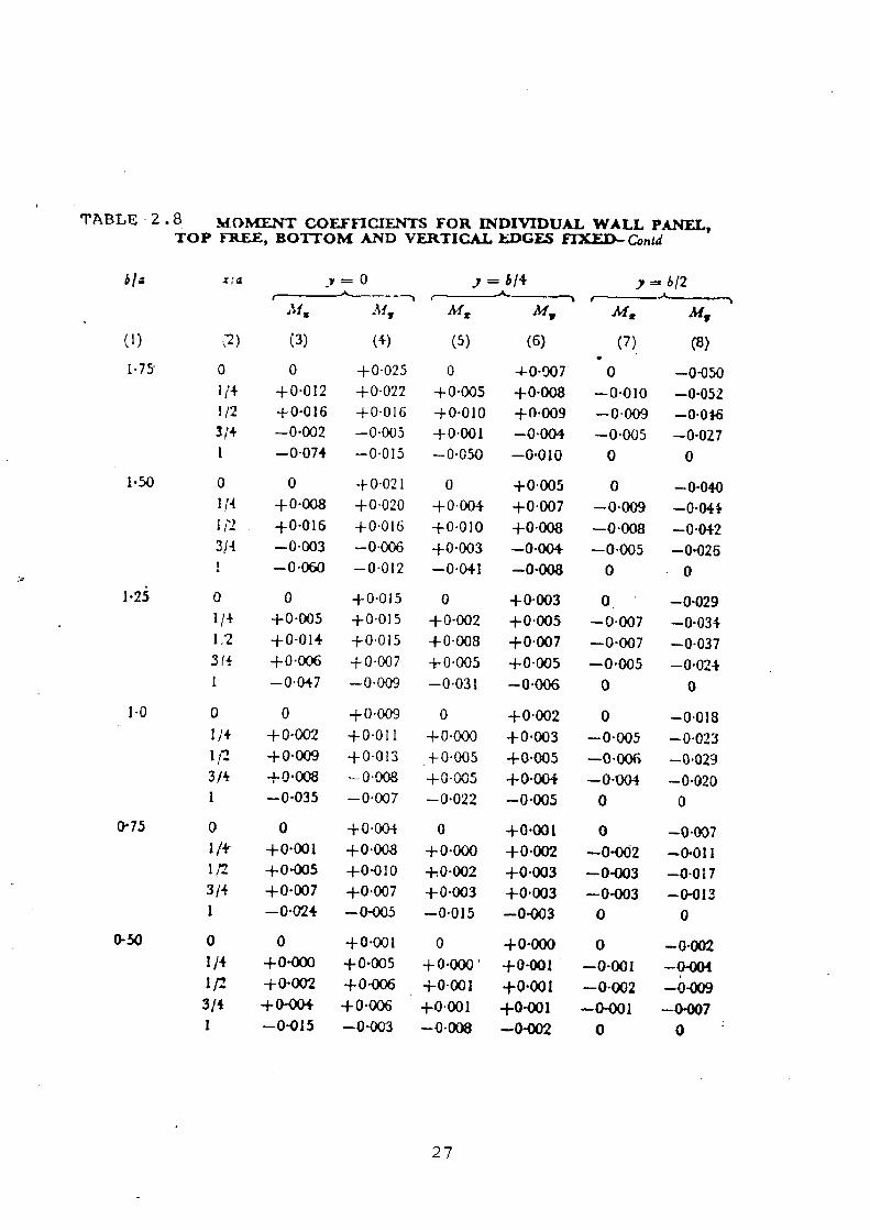
TABLE 2.8 MO T COEFFICIENTS FOR INDIVIDUAL WALL PANEL, TOP FREE, BOTTOM AND VERTICAL 1 DGFS FIXED-Conk!
y = b/4 ) = b/2 ,Lis hf, Ms M, M= My
(1) ;2) t3) (4) (5) (6) (7) (8) 1.75- 0 0 +0-025 0 4-0.007 • 0 -0-050
1/4 +0-012 +0-022 +0-005 +0-008 --0.010 -0-052 1/2 +0-016 +0-016 +0.010 +0.009 -0-009 -0.046 314 -0-002 -0.005 +0-001 1
-0.004 -0-005 -0-027 -0-074 -0.015 -0.050 -0.010 0 0
1.50 0 0 +0-021 0 +0.005 0 -0-040 114 +0-008 +0.020 +0.004 +0.007 -0.009 -0.044 1/2 +0.016 +0.016 +0.010 +0.008 -0.008 -0.042 314 -0.003 -0.006 +0.003 -0.004 -0-005 -0-026 1 -0-060 -0.012 -0.041 -0-008 0 0
1.25 0 0 +0.015 0 +0-003 0. -0-029 1/4 +0-005 +0-015 +0-002 {-0.005 -0-007 -0-034 1,2 +0-014 +0.015 +0-008 +0.007 -0.007 -0-037 3(4 +0.006 +0.007 +0.005 +0-005 -0.005 -0.024 1 -0.047 -0-009 -0.031 -0-006 0 0
1.0 0 0 +0-009 0 +0.002 0 -0.018 1/4 +04)02 +0-011 +0.000 +0.003 -0.005 -0.023 1,r2 +0-009 +0-013 4-0-005 +0.005 -0.006 -0.029 3/4 .1-0.008 -0-008 ±0-005 ±0.004 -0-004 --0.020 1 --0.035 -0.007 -0.022 -0.005 0 0
0.75 0 0 +0-004 0 +0.001 0 -0.007 1/ +0.001 +0.008 +0.000 +0-002 -0-002 -0-011 1/2 ±0.005 +0.010 +0-002 +0.003 -0-003 -0-017 3/4 +0.007 +0.007 +0.003 +0.003 -0-003 -0-013 1 -0-024 -0-005 -0.015 -0-003 0 0
0-50 0 0 +0-001 0 +0.000 0 -0-002 1/4 +0.000 +0.005 +0-000' +0.001 -0-001 -0-004 1/2 +0-002 +0-006 +0-001 +0-001 -0-002 -0.009 314 +0-404 +0-006 +0.001 +0-001 -0-001 -0-007 1 -0-015 -0.003 -0-008 -0-002 0 0
27

(4) +0.070 +0.061 +0.049 +0-030 +0-061 +0-053 +0-044 +0.027 +0.045 +0.042 +0-036 +0.024 +0.036 +0.035 +0-032 +0.022 +0.027 +0.028 +0-027 +0.020 +0.017 +0-020 +0-023 +0.017 +0-010 +0-013 +0.017 +0-015 +0.005 +0.008 +0-011 +0-012 +0.002 +0-004 +0- 006 +0.008
(5)
0 +0-015 +0.032 + 0.034.
0 +0.010 +0-025 +0.030
0 +0.006 +0-020 +0.025
0 +0.005 +0.017 +0.021
0 +0.003 +0012 +0.017
0 +0.002 +0.009 +0.013
0 +0.000 + 0.005 +0.009
0 +0.000 +0-002 +0.006
0 +0-000 +0-001 +0-002
Af t, (6)
+0.027 +0.028 +0.026 +0.018 +0.019 +0.022 +0.022 +0.016 +0.011 +0.014+0.016 -4-0.014 +0-008 +0.01 1 +0-014- +0-0 12 +0.005 +0.008 +0.01 1 +0.01 1 +0.003 +0.005 +0.009 +0.009 +0.002 -}-0.003 +0.006 +0.007 +0.001 +0.002 +0.004 +0.004 +0.000 +0-001 +0.002
'+0-002
(2) 0 1/4 1/2 3/4 0 1/4 1/2 3/4 0 1/4
1/2
314 0 114 1,2 3/4 0 1;4 1112 3f4 0 l:4 l 2 3,4 0 1;4 1/2 3;4 0 1,4 1112 3;-~ 0 1/4-1/2 3/4
TABLE .2.9 MOMENT COEFFICIENTS FOR INDIVIDUAL WALL PANEL, TOP FREE, BOTTOM HINGED, VERTICAL EDGES FIXED
y= b~4
a = height of .cc wall
b = width of the va11
w - density of the liquid
Horizontal moment = Mt' ua 3
Vertical moment = Al. u•a3
Mz (3)
0 +0.028 +0.049 ±0.046
0 +0.024 +0.042 +0.041
0 +0.016 +0-033 ±0.035
0 +0.013 -}-0.028 +0.031
0 +0.009 ±0.022 -0.027
0 ±0.005 +0,017 +0.021
0 -+-0.002 +0.010 -x-0.015
0 +0.001 +0-005 +0010
0 +0.000 +0.002 +0.007
y = b/2
Mx MY
(7) (8) 0 -0-196
-0-034 -0-170 -0-027 -0-137 -0.017 -0-087
0 -0-138 -0-026 -0-132 -0.023 --0.115 -0-016 -0-078
0 -0.091 -0.019 -0.04 -0.018 -0.089 -0-013 -0.065
0 -0-071 ---0.015 -0-076 -0-015 -0-076 -0.012 -0.059
0 -0-052 -0-012 --0-059 -0.013 -0-063 -0-010 -0-052
0 -0-034 -0.008 -0-042 --0.010 -0-049 -0-009 -0-044
0 -0-019 -0.005 -0.025 -0.007 -0-036 -0.007 -0.036
0 -0.008 -0.003 -0.013 -0.004 -0-022 -0-005 -0-026
0 -0-003 -0-001 -0-005 -0.002 -0-010 -0-003 -0-014
b _ 2 2
L R
FIXED ( FLXED g
HANGED
X x/a JO E/a
(1) 3.00
2.50
2.00
1.75
1.50
1.25
1.00
0, 75
0.50

TABLE " 2 . I0 MOMENT COEFFICIENTS FOR INDIVIDUAL WALL PANEL, TOP AND BOTTOM HINGED, VERTICAL EDGES FIXED
a = height of the wall
b - width of the wa11
w = dcriuity of the liquid
Horizontal moment = M„ wa3
Vertical moment = MZ wa3 --
►1~rGED
FIXED FIXED-J a
HINGED j_j•
Y
X b/a x/a y= 0 y = b~•r y s
~---, b/2
~Lf~ M y Mx M, alts M y (1) (2) (3) (4) (5) (6) (7) (8) 3 .00 1/4 +0-035 +0-010 +0.026 +0-011 -0.008 -0-039
112 +0-057 +0-016 +0-044 +0-017 -0-013 -0.063 3/4 +0-051 +0-013 +0-041 +0.014 -0-011 -0.055
2.50 1/4 +0.031 +0-011 +0-021 +0-010 -0-008 -0.038 1/2 +0-052 +0.017 +0-036 +0-017 -0.012 -0.062 3/4 +0-047 +0.015 +0.036 +0.014 -0-011 -0.055
2.00 1/4 +0-025 +0.013 +0-015 +0-009 --0.007 -01037 112 +0-042 +0-020 +0-028 +0.015 -0.012 -0.059 314 +0041 +0-016 +0.029 +0.013 -0-011 -0.053
1 .75 1/4 +0-020 +0.013 +0-012 +0-008 -0-007 -0-035 1/2 +0.036 +0.020 +0-023 +0-013 -0.011 -0.057 3/4 +0.036 +0.017 +0-025 +0-012 -0.010 -0.051
1.50 1/4 +0 - 015 +0.013 +0-008 +0-007 -0.006 -0-G32 1/2 +0.028 +0.021 +0.016 +0.011 -0.010 -0-052 3;4 +0.030 +0.017 +0-020 +0.011 -0-010. -0.048
1.25 1/4 +0.009 +0.012 +0-005 +0.005 -0.006 -0.028 1/2 +0019 +0-019 ±0.011 +0.009 -0.009 -0-045 314 -1-0.023 +0.017 -4-0.014 ±0-009 -0.009 -0.043
1.00 1/4 +0-005 +0.009 +0.002 +0.003 --0,004 -0.020 1/2 +0 01 1 +0.016 +0-006 +0-006 -0.007 -0.035 3/4 -f 0-016 +0-014 +0-009 +0-007 -0-007 -0-035
0.75 1 -/4 +0001 +0.006 +0.000 +0-002 -0.002 -0.012 1/2 +0.005 +0.011 +0.002 +0-003 --0.004 -0.022 314 -{-0009 +0.011 +0-005 +0-005 -0.005 -0-025
0.50 1/4 +0.000 +0-O0.; 0.000 4-0-001 -0-001 -0-005 1/2 +0-001 +0-005 +0-001 +0-001 -0.002 -0.010 3/4 +0.004 +0.007 +0.002 ±0-002 -0.005 -0.014

CHAPTER 3
CODAL PROVISIONS
3.1 IMPERVIOUSNESS OF CONCRETE
The concrete should be rich in cement content. Proportion of fine
and coarse aggregate to cement should be such that it gives workable mix
with high value of tensile strength. Low value of w/c ratio is adopted
keeping in view the method to be used for compaction and type of aggregate.
As per IS:3370 (Part 1)-1965 min, grade of concrete and min. cement content
is M20 & 330 kg/m3 respectively. Where as IS:3370 (Part 1) draft recommends
M25 as min. grade and min. cement content as per IS:456-1978. Max. cement
content is restricted to 530 kg/m3.
3.2 CONTROL OF CRACKING (a) Design of member while ignoring tensile resistance of concrete
and calculated tensile stress on liquid retaining face does not exceed limits in IS:3370-Part 1I-1965. (Table 3.1).
(b) The expansion and contraction of concrete due to temperature variations or shrinkage and swelling of concrete, if restrained can cause cracking of R.C.C. member.
The risk of cracking due to contraction and expansion can be
controlled by providing suitable joints at predetermined locations.
To guard against shrinkage cracks it is necessary to ensure that all
parts of tank are kept damp during construction and curing, the tank should
be filled with water as early as possible.
30
(c) In thick section there is likelihood of cracking as
consequence of temperature rise during hydration of cement and
subsequent cooling. In these cases a low heat evolution cement
may be used. For effect of stresses caused due to drying
shrinkage or differences in temperature, the following values
of coefficient of expansion and coefficient of shrinkage may
be adopted.
coefficient of expansion 11 x 10-6
Coefficient of shrinkage initial shrinkage - 450x10 6
of original length drying shrinkage 200 x 10 6 of original length
3.3 METHOD OF DESIGN
First revision of IS:3370 (Part II)-1965 includes limit state design
in addition to working stress method with slight modification in it.
3.3.1 Working Stress Method [ 1,51
(i) Permissible stress in concrete
(a) For Resistance to cracking :
For calculations relating to the resistance to cracking, the
permissible stresses shall conform to the values specified in Table 3.1.
(b) For Strength Calculation :
In strength calculations, the permissible concrete stresses shall be
in accordance with Table 3.2.
31

(ii) Permissible stress in steel
(a) For Resistance to cracking
The tensile stresses in the steel will necessarily be limited by the
requirement that the permissible tensile stress in the concrete is not
exceeded, so that tensile stress in steel shall be equal to the product of
modular ratio of steel and concrete, and corresponding permissible tensile
stress in concrete.
(b) For Strength calculations
For strength calculations, the permissible stresses in steel shall
conform to the values specified in Table 3.3.
3.3.2 Limit State Method [4,51
(i) Limit State Requirements
Recommendation given in IS:456-1978 for limit state of collapse and
serviceability are applicable but maximum crack width for direct tension
and flexure shall not exceed 0.2 mm.
(ii) Limit State Design
(a) Design and detailing of reinforcement is same as specified in
section 5 of IS:456-1978 except that steel grade in limited to Fe
415.
(b) Crack width : They may be deemed to be satisfactory if steel stress
under service conditions does not exceed 115 N/mm2 for mild steel
and 130 N/mm2 for HYSD bars.
32

(i) Crack width assessment in mature concrete due to flexure
Provided that strain in tensile reinforcement is limited to 0.8fy/Es
and stress limited to 0.45fcu. The design surface crack width in flexure
may be calculated from equation given below :
W _ 3 acr£m
1+2acr - Cmin D-X
Where, W = surface crack width
nearest longitudinal bar.
E m = average strain at level where crack of considered
Cm• .. = min. cover to tension steel.
D = overall depth of member
X = depth of N.A. (neutral axis)
£m =C1 -e2
E 1 = strain at level considered
e2 = strain due to stiffening effect of concrete
Stiffening effect is assessed from following equation.
12 bt (Ds- X) (a - - X) (design crack width of 0.2 mm.)
l.5bt(D-X £2 =
X) (a - X) (design crack width of 0.1 mm) s s
33
Where, bt = width of the section at the centroid of tensile steel.
D = overall depth of member
Es = modulus of elasticity of steel.
As = area of tensile reinforcement.
a' = distance from the compression face to the point at
which crack width is considered.
(ii) Crack Width Assessment in mature concrete due to Direct Tension :
w =3acrEm
E2— 2 A (limiting design crack width of 0.2 mm.)
E2 = b (limiting design crack width of 0.1 mm.) s s
3.4 MINIMUM REINFORCEMENT
As per IS : 3370 (Part I1) 1965 minimum reinforcement in each of two
direction at right angle shall have area of 0.3% of concrete section upto
100 mm, 0.2% for section of thickness above 450mm and for intermediate
values it is interpolated. In the revised draft this has been changed and
it states that minimum Reinforcement at right angle in each of two
directions shall not be less than 0.35% of surface zone for HYSD and 0.64%
for mildsteel. Surface zone are shown in Fig. 3.1.
34

3.5 MINIMUM COVER
As per IS:3370-1965 Min. cover is 25 mm or dia of bar whichever is
greater and for corrosive soil or water additional cover of 12 mm is
provided. Where as revised draft recommends cover of 40 mm or dia of bar
whichever is greater and 15 mm addition cover for corrosive soil or water.
35

Under 300 mm
No bWom reinforcement
NOTE. For D 500 mm, e%tums each reinforcement face Control$ • O/Zdepth of Concrete. i'•.
For[J > 500 mm, ettuma each rtintorcement fa9jt controls 250 mrn
depth of concrete, ignoring any central core b.yond this surlOCQ depth.
Surface zones: wells and suspended slabs
300 mm
500 mm b
UlOO mm
Over 1 500 mm
D
t__ ____ Surface zones: ground slabs
2SO mm
00 mm'
Fig.3_ : Surface Zones
36

Table - 3.1
Permissible concrete stresses in calculations relating to resistance to cracking.
Permisslble srresset Grate of Shear concrete Q
Direct Tendon Tiny/on due to binding bja (ae,) (° 0 )
M 20
M 25
hi 3(1
N135
hi 411
N Omni
it
1.2
13 (1.3):
15(1 •4)c
1 . 6
17
Nlnmm2
1 . 5
17
18(1 8)" 20(2,O)"
22
24
N/mmt
1.5
1 .7
19(1.9):,
2.2(2.1) ' 2•
2.7
Values as per IS:3370 First Revision Draft.
TABLE .2 PERMISSIBLE CONCRETE STRIF.sSi --;S IN STRENGTH CAI,Cllt,A'rIONS
i;rzcle of Pcrmissible Concrete Stress, N/mint Concrete----------------------------
C oml)ression Shear Bored (average) for
Direct: 1)ur to plain mild steel Bend.in.>; bars in tension
1) (2) ( -3) (4) (5) As per Table
17 of
IS 456:1978
H 25 6.0 8.5 For H 25 and 0.9 30 , fi , 0 10. 0 H 30 Concrete 1 0
NOTES:
1) The bond stress given in column 5 shall . be increased by 25 percent for bnrG in compression..
2) In the case of deformed bars conforming t.o IS:1786-1979 the
bond stresses given abo.•e may be increasd by 40 percent.
3) The anchorage (average) bond stresses for horizontal bars
which are in sections in direct tension shall not exceed 0.7 times the above values.
37
Table 3.3 Permi:;s'1>le stresses in Flee) Reinforcement for Strerh
CaIculalicn
Permissible stresses in N mm"
iyge of stress Plain round mild steel 111gb yield :t r~•n,; (h (mrcemrnt bars conforming to grade defnrmrd bar
->f -IS 182 (Part I)-1166 bars c-Oit[ o alit) ,. tc IS: I7R6- ) 9J6f) r,. 18: 1 1 30 1 `)C C
1 icn;ile stress it 115 ISo? members under direct
tension (a ) S
2. Tensile stress in
members in bcndi-ig
{° st )
(a) On liquid retaining
115
} 50
face of members
(b) On face away from
115
1 5 0)
liquid for members
less than 225 mm
(c) On face away from
125
I. o liquid for members
225 mm or more in
thickness
3. Tensile stress in shear
reinforcement (v Sv
(a) For members ic than
115
1 50)
225 mm thickness
(b1 For members 22S or
125
175
more In thlc.ncss
4. Compressive stress in 125 1-'S
columns subject^d to
direct load (a- s c:

CHAPTER 4
JOINTS IN WATER TANKS
As per IS:3370(Part I)-1965 Joints shall be categorized as below
(a) Movement Joints
(b) Construction Joints
(c) Temporary Joints
4.1 MOVEMENT JOINTS
There are three categories of movement joints.
4.1.1 Contraction Joints
A movement joint with a deliberate discontinuity but no initial gap
between the concrete on either side of the Joint, being intended to
accommodate contraction of the concrete. A distinction should be made
between a partial contraction joint (Fig. 4.1) in which only concrete is
interrupted and the steel running through and a complete contraction joint
(Fig.4.2) in which both concrete and steel are interrupted. Its spacing
should not exceed 7.5 m.
4.1.2 Expansion Joints :
A movement joint with complete discontinuity in both reinforcement
and concrete, intended to accommodate either expansion or contraction of
the structure (Fig.4.4). Its spacing should not exceed 30 m.
4.1.3 Sliding Joints :
A movement joint with complete discontinuity in both reinforcement
and concrete at which special provision is made to facilitate relative
39

movement in place of the joint.Fig.4.5 shows sliding joint between floor &
wall in cylindrical tank.
4.2 CONSTRUCTION JOINTS
During construction of wall, height of lift is restricted generally
to 2m. so to achieve subsequent continuity without movement, construction
joints are provided (Fig.4.3).
4.3 TEMPORARY OPEN JOINTS
A gap temporarily left between the concrete of adjoining parts of a
structure which after a suitable interval and before the structure is put
into use , is filled with mortar or concrete completely as shown in
Fig.4.6.
Plan showing location of expansion & contraction joint is shown in
Fig.4.7.
40
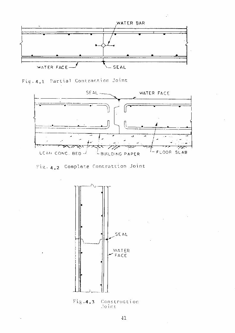
WATER RAR
Fig,. 4.1 Partial Conrrr.rion Joint
SEAL- WATER FACE
- ______ -
r
--____________
-= -- H R k
- / - I -
- f -2\ ,c '--' /- -
LF-r4 CONC. BED -~ BUILDING PAPER - FLOOR SLAB
Fi.~,. 4 .2 Complere C.ontrattion Joint
SEAL
YAT ER FACE
Fib .4.3 Constructi on Joint,
41

WATER BAR
SEAL
JOINT FILLER
t S AL -
GM'— -1 J-+ 'WATER FACE Fig.4.4 Expansion Joint
Fig.4.5 Sliding Joint 51R1P. PAINTING
CONCRETE GAP LATER ' INITIAL GAP LATER FJLE
FI CO F!LD W17 I FsLLEO WITE4 CONCRETE
`—vPR2 P Mf u JOINT SURFACE S
IT,JITl1L GAP - " GTRIP PAINTING JCIN. T SE::LING f.
r,LLIH'-
C Fi c. 4.6 Te'npor_ory Open Joints
JL— ""T SEALING COMPOUND
B
4'2

-,- ~ mn --~-`~_- 7'~~rn 7 5/n - ~m | ' --~---- ---~~=~-- ' °,
E
- -
` \ ~ /|
/ /
JOINTS
~ |
~ 7 -~-----l---- ------/~--
` __'_
' ~ _
/ Fig. 4.7 Plnn Shnpin .}ni.nr~
D7TATLS OF v\RT0|S .JOTN79 TN TANKS
43

CHAPTER 5
DESIGN ASPECTS OF UNDERGROUND TANKS
The dimension of tank can be worked out from total capacity of tank
required. The design of tank is done on the no crack basis. Various steps
of design as per IS:3370 are given in following paragraphs.
5.1 DESIGN OF WALLS OF CIRCULAR TANK
(i) Computation of forces including seismic effect [61
Case I : Empty tank with full earth pressure
Hoop compression = Cf Ka H 1 D/2
Bending Moment = Cf Ka a' H13
Shear force at base = Cfs Ka a' H12
Where, Cf = coefficient for hoop compression & bending moment.
Cfs = coefficient for shear force at base.
a' = soil density
HI = height of soil
D = diameter of tank
Ka = coefficient of lateral acting earth pressure.
For dynamic case
1 2 (l±av)Cos2(0-a)
Ka — cos (A) cos (+A) I +A sin(o+.5) sin(o-a) (i) cos (+x) —J
]
14

where, 0 & a = angle of internal friction of soil and angle of friction
between wall and earthfill respectively
av = vertical seismic coeff. = 0.5 ah
= tan-1 a h ±a
V
a lp = horizontal seismic coefficient = (3la0
1 = Importance factor = 1.5 for tanks
ao = basic horizontal seismic coefficient.
If earthfill is saturated, then
(a) The value of a is taken as 1/2 of 6 of dry backfill
a (b) A=tari-1 ws
v
ws = saturated unit weight of soil in gm/cc
For static case to find Ka put ah = av A = 0 in eq.(i)
Case-2 - Tank is full with no earth pressure Dynamic Case
Hoop tension = c f w H D/2 1 +ah x 1.732 tanh [1.732Dll 2HJj
Bending moment = cf wH3 1 +ahx 1.732 tanh 1 .732Dul 2H ij
Similarly shear force = cfs wH2 l+ahx1.732 tanh 1D
45

For static case put ah = 0
From these two cases choose the higher value as design force.
(ii) Thickness of Wall (T)
Thickness of wall (T) = Ay
where fc = permissible stress in concrete in bending
Thickness should not be less than 150 mm or (30H + 50)mm whichever
is greater.
(iii) Calculation of Steel
Area of steel for cantilever action (Ast) = B. M °sc Jd
Spacing of Steel (sv) = 1000 st
where, 0 = diameter of bar
Bars are extended beyond the critical section at least by
development length Ld = T bd
st ` permissible tensile stress in steel
Bbd = permissible bond stress.
Hoop reinforcement (Ash) = Hoop a Tension st
Actual area of hoop steel should be greater than required area for
tensile stress in concrete given by.
46

= hoop tension < cr t + m- sh ct
o-t = tensile stress in concrete
°rct = permissible tensile stress in concrete
m = modular ratio
Shear stress (pt) in wall is checked as
1000 * it * 02 Pt s v
Permissible shear stress = k-rc > Shear stress
Otherwise increase the thickness of wall. Usually shear is not
critical.
(iv) Distribution Steel:
Distribution steel (0.3%) is provided where steel is less than
minimum steel required.
5.2 DESIGN OF WALLS OF RECTANGULAR TANK.
Various steps involved in design of rectangular tanks as per IS:3370
are as follows.
(i) Calculations of design forces
Various design forces like horizontal & vertical bending moment in
both walls, and shear forces are calculated using various tables given in
IS 3370 Part (IV) for tank full & empty cases. Signs of various
47
coefficient are reversed for tank empty case. These forces are calculated
similarily as calculated in circular tank in Art.5.l. For dynamic case `D'
is replaced by length of rectangular tank.
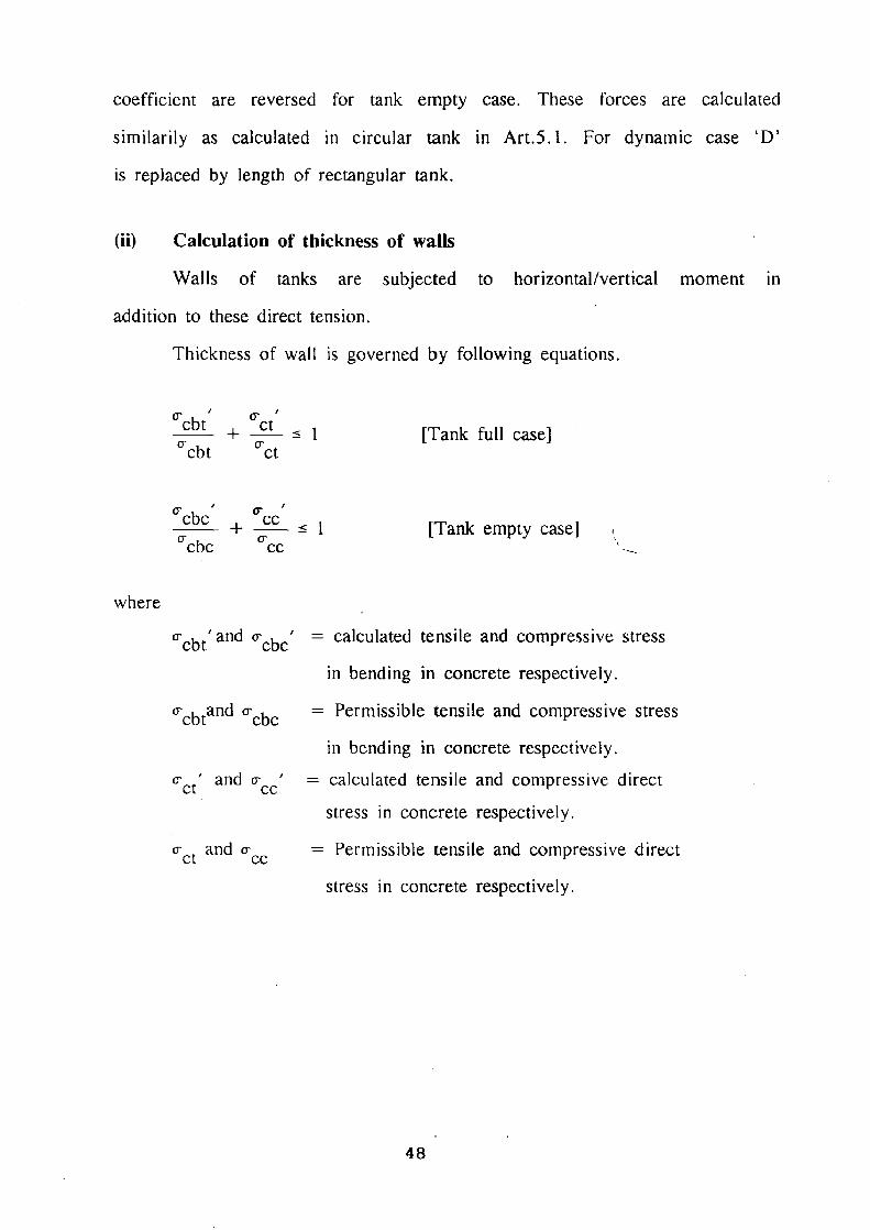
(ii) Calculation of thickness of walls
Walls of tanks are subjected to horizontal/vertical moment in
addition to these direct tension.
Thickness of wall is governed by following equations.
cbt' + pct, cbt °ct
[Tank full case]
(Tcbc + Crcc a'cbc cc
[Tank empty case]
where
0'cbt and a'cbc' = calculated tensile and compressive stress
in bending in concrete respectively.
°'cbtand Q'cbc = Permissible tensile and compressive stress
in bending in concrete respectively.
pct' and a-cc' = calculated tensile and compressive direct
stress in concrete respectively.
ct and a-cc = Permissible tensile and compressive direct
stress in concrete respectively.
MV

(iii) Reinforcement in Horizontal direction
Horizontal bending is coupled with direct tension due to water or
earth pressure in walls at right angle to walls under consideration.
Horizontal steel is provided for both hogging & sagging case as shown in
Fig.5.1 & 5.2. Various steps for finding hogging and sagging steel are as
follows
(i) Depth of N.A. = kd
where k = me mc & d = T - effective cover
Eccentricity of Tensile force (et) from center of section
e = Bending moment t Shear force
Eccentricity from the center of steel
ecs = et - T/2 - effective cover
(ii) Distance of C.G of compressive zone from reinforcement
r _ depth of N.A. L U 3
SF (ecs + L) (iii) Area of steel (Asth) —
S
o's = permissible stress in steel whose value depends upon condition
that whether it is in contact with water or not.
49

T/4 L - __ __
---1 J9
T/2 ~1-
Waier face
e ecs t
Direct tension
Fig. 5 a : flogging Moment
• Di rcr: tension
T
Horizontal steel
T/Z
Water Face
fig. 2 : Sagging Moment
2,470 S/
401

(iv) Reinforcement in Vertical Direction
Reinforcement in vertical direction for hogging and sagging moment
is given by
B.M. in vertical direction Astv s Jd
During curtailment of bars development length criteria should be
satisfied.
(v) Distribution Steel
Provide distribution steel equal to 0.3% in both direction if
required.
5.3 DESIGN OF BASE SLAB
If both rectangular and circular tanks with flat or sloping base
rests on hard rock and have flexible joint at base then base slab of
nominal thickness (200 mm) with minimum (0.3%) steel is provided. But if
rigid joint is provided then flat slab is designed like circular and
rectangular slab fixed at ends.
5.3.1 Design of sloping base slab
(i) Pyramidal bottom
Area of steel for meridional tension
A = Meridional Tension As Permissible tensile stress in steel
Steel spacing is increased toward the bottom.
51

Thickness of base slab =FTOPC J woo
fc = permissible stress in bending in concrete
This steel is provided about the periphery of Pyramidal bottom with
increased spacing toward bottom.
(ii) Conical Bottom:
Conical bottom is designed like circular tank with flexible joint.
Max. hoop tension = wHD/2
H = height of cylindrical portion above junction with
cone.
a's .= Permissible stress in steel in direct tension.
Area of steel (Ash) for hoop tension = ;HD . s
If a'ct is permissible stress in concrete in direct tension then
thickness (T) is governed by eqn. given below:
wHD/2 crct 1000T + (m sh
Projection of base slab (e) is governed by uplift pressure when tank
is empty.
Uplift pressure (UP) = w(H1 - WT)
Net uplift Pressure (NU) = UP - self weight of tank.
For circular tank gravity load = [(D+e)2 D2]i-i1
For rectangular tank gravity load = l(L+e)(B+e)-(LxB)I'XH f
52

Gravity load > FOS uplift force
Factor of Safety as per IS:3370 (Part I) is 1.20.
5.4 TANK DESIGN AS A CANTILEVER RETAINING WALL
If L/H ratio in rectangular tanks exceeds the value of 3.0 and
diameter in circular tanks exceeds 12 m, then tanks are designed like
cantilever retaining wall. The sides of tank are monolithic with base slab
which act independently of the floor. The cantilever walls must be
reinforced on both faces. The vertical main reinforcement on water face of
wall is provided to resist B.M. caused when tank is full of liquid and no
earth pressure is acting. Similarly, the reinforcement on faces of wall in
contact with earth is provided to resist the bending moment, when tank is
empty and back earth presence is fully active. Base slab is also designed
for above two conditions. In the remaining portion of base slab, nominal
thickness with nominal reinforcement is provided. In all cases, water table
position is taken in account.
Retaining wall must be in equilibrium under given system of forces.
(1) Resisting moment must be more than the overturning moment. Total
stablizing or resisting moment is at least 100% greater than total
overturning moment.
FS . Resisting moment 2.0 Overturning moment
53

2. Horizontal component of the lateral pressure tends to slide the wall
along the base.
Force opposing sliding = µ x EW
FOS = µms >- 1.5
EW = Sum of vertical loads
u = Coefficient of friction between base and soil
P = Total horizontal force tending to slide wall
3. Maximum and minimum pressures are given by
EW 6e p1 = 1 + (5)
P _ EW 1 _ 6e~
P1 = Intensity of soil pressure at toe
P2 = Intensity of soil pressure at heel
EW = Sum of vertical loads
P 1 should be not exceed bearing capacity of soil. P2 should not be
negative. So sum of all vertical forces and horizontal earth pressure
should cut base of wall within middle third of the base.
54
The steps followed in design are :
1. The preliminary dimensions of tank stem, heel and toe slab are worked
out.
2. The stability of tank is checked in tank empty and tank full cases and
dimensions are accordingly decided.
3. Design of sides is carried out as cantilever wall, the reinforcement
at both faces is provided according to B.M. calculated.
4. Design of toe slab is done in both cases of tank empty and tank full.
The reinforcement is given according to resultant pressure diagram.
Shear is checked at distance equal , to effective depth of toe slab from
the face of stem.
5. Heel is designed as cantilever slab fixed at back face of stem. The
reinforcement is provided according to resultant pressure diagram.
Critical section for shear is considered at stem face. The main
reinforcement must be extended beyond the critical point by
development length.
55
CHAPTER 6
SOFTWARE ASPECTS
6.1 GENERAL
The software package "RCTANK" has been developed for analysis, design
and drafting of RC underground tanks in FORTRAN 77 language on Tata Elexi-
3220 main frame computer. It can also be run on personal computer. It
mainly consists of two parts as follows
1. Numerical Analysis and Design
2. Drafting
For numerical analysis and design of both rectangular and circular
tank, a program COMBIN.FOR has been developed. This program provides a
friendly environment to user. The program is developed on the basis of
formulation presented in Chapter-5. The program is very general in nature.
It can handle varying tank depth in soil for both rectangular and circular
tanks. Circular tank design program has been taken from thesis work of ANUJ
KUMAR JAIN and modified to adjust with the program for design of
rectangular tank. This program can well be used for design of tank directly
resting on ground also. The user gets facility of not referring to
permissible stresses of materials as they are built in, according to choice
of user for concrete grade and steel bars to be used.
56

Flow charts of program and its main subroutines have been presented in
Fig.6.1 to 6.6 .
Rectangular tank walls have been designed for following end
conditions:
1. Top free, bottom fixed.
2. Top free, bottom hinged
3. Top & bottom hinged
For first condition if L/H ratio exceeds the value 3, then walls are
designed like cantilever retaining wall.
Similarly circular tank walls have been designed for following end
conditions -
1. Hinged at base, free at top
2. Fixed at base, free at top
(a) Small diameter tank
(b) Large diameter tank
Large diameter tank (D > 12 m) is designed like cantilever retaining
wall.
Second part of 'RCTANK' is the drafting of sectional elevation and
plan of designed tank. Drafting of rectangular tank has been dealt in this
57

dissertation work. It contains three program namely DRAFTI.FOR, DRAFT2.FOR
and DRAFT3.FOR.
Based on these objectives, the functions of interactive program are
given below :
1. Interpolation of coefficient for tension and moment according to types
of tank and base conditions.
2. Computation of bending moment and tension in cylindrical tank and
bending moment on horizontal and vertical direction for rectangular
tank based on type of tank.
3. Design of wall based on coda] provisions.
4. Design of base slab for slab end condition and water table position.
5. In case, diameter is greater than 12 m or L/H ratio is greater than 3,
then design of tank wall like cantilever retaining wall is carried
out.
6.2 SOFTWARE FOR ANALYSIS, DESIGN AND DRAFTING :
6.2.1 Input to Main Program
The input values which are asked interactively on screen mode in main
program are -
* Name of output file
* Code for type of tank.
1. Rectangular tank
2. Circular tank
If code is 1; than following input values are asked.
* Capacity of tank in litres
* Depth of tank in soil
* Unit weight of material filled in tank in N/m3
* Unit weight of soil
* Bearing capacity of soil
* Codes for square/rectangular tank
* Free board in metres
* Water table position below G.L.
* Codes for End conditions.
6.2.2 Description of Subroutines:
The subroutine which are used for analysis and design are listed
below:
1. CENT
3. TEMPT
5. STRESS
7. THIC
9. MINIBM
11. REINFV
13. MOMENT
15. FBSLAB
17. CANTTANK
19. CIRCULAR
2. I NTPOL
4. TFULL
6. BIGN
8. SMAX
10 REINF
12. HOOPREIN
14. HGSLAB
16. CFSLAB
18. CALCULN
m

1. CINT
This subroutine is used for linear interpolation of coefficients for
moments in horizontal and vertical direction depending on the value of Y (Y
= L/H). The coefficients of corresponding locations are interpolated and
transferred to main program through argument. This subroutine is required
in rectangular tank only. Interpolated coefficients are printed out in
output file.
2. INTPOL
This subroutine is used only for circular tank case for linear
interpolation . of coefficients of hoop tensions and moments in tank
according to base condition. H2/Dt ratio as evaluated in main program is
inducted as an argument, correspondingly interpolation is done and
interpolated coefficients are given out.
3. TEMPT
This subroutine is used in both rectangular and circular tank cases.
This is also used for calculation of static and dynamic earth pressure for
retaining wall case also. In circular tank case, this is used to calculate
the hoop compression and moments in wall for tank empty case. This
subroutine is called in subroutine CIRCULAR. For rectangular tank it
calculates, horizontal and vertical B.M. at different points. In carrying
out analysis option is given to user for analysis by static earth pressure
or static and dynamic earth pressures both. The submergence of soil mass is
also taken into account. Dynamic pressure analysis is done according to IS

: 1893-1984. Hoop tension and moments in circular tank case and horizontal
and vertical B.M. in rectangular tank case are printed out in output file.
The input data, which is asked interactively in it, are as given
below:
1. Value of angle of internal friction of soil (in degrees)
2. Value of angle of friction between wall and soil (in degrees)
3. Code for conditions under which tank is to be designed
i) Static Pressure
ii) Static and dynamic pressure
4. Seismic zone in which tank is located if dynamic pressure is to be
included.
4. TFULL
This is also used in both types of tanks. For calculation of hoop
tension and moments for circular tank and B.M. for rectangular tank in
horizontal and vertical direction, for case when tank is full and no earth
pressure is there. Here option is given to user, whether he wants to
consider the relief from earth pressure or not. Accordingly forces are
calculated and printed out in output file.
The input given in screen mode is
1. Code for condition
a) half liquid pressure acting from inside
b) full liquid pressure acting from inside
MI

5. STRESS
This subroutine is used for computing values of design constants i.e.
modular ratio, neutral axis depth ratio, lever arm, moment constants,
permissible stress in steel etc. These are computed out according to chosen
type of concrete and steel. Permissible stresses are increased in dynamic
case. All permissible stresses are in built in this subroutine.
6. BIGN
This subroutine is used only in rectangular tanks for calculating
maximum absolute B.M. for both, tank full and tank empty cases.
7. THIC
In this subroutine, thickness of wall section of rectangular tank is
calculated. If the maximum bending moment value calculated by subroutine
BIGN lies below or at X/H = 0.5, then corresponding to this , thickness
upto half of height from base, is provided. In rest of upper portion
corresponding to maximum absolute bending moment acting in this portion,
thickness is provided. User may change these, these are displayed on
screen.
8. SMAX
This is used in rectangular tank for calculation of maximum positive
B.M. at different X/H values by comparing the B.M. values at different
points along length or width of wall. In this, maximum positive horizontal
and vertical B.M. values are calculated.

9. MINIBM
This works like above subroutine but difference is that it calculates
the maximum negative horizontal and vertical bending moment values.
10. REINF
This subroutine is used for calculation of area of steel and its
spacing at outer and inner face in horizontal direction. In this, a message
is displayed on screen. If spacing is either less than 100 mm or greater
than 450 mm, then diameter is required to be changed. Diameter, area of
horizontal steel and spacing are passed as argument to subroutine CALCULN
where it is called. Minimum area of steel requirement criterion has also
been introduced.
11. REINFV
This acts similarly as REINF but difference is that it calculates the
steel in vertical direction at both faces.
12. HOOPREIN
This subroutine is used in circular tank to calculate reinforcement
due to hoop tension. The minimum reinforcement according to codal
provisions is calculated and if hoop reinforcement according to grade of
concrete and steel is less than minimum, then at that level minimum hoop
steel is provided. The option is available for user to give spacing as is
needed. In the last part the tensile stress in section is checked and if
greater than permissible, message is displayed to change the section.
Results are written in output file.
63

13. MOMENT
This subroutine gives out the vertical reinforcement details at water
face and away from water face. First of all, thickness of wall required for
moment consideration is worked out. If assumed thickness is less then
required, program gives error message and returns to main •to calculate new
moment according to H2/DT ratio. The area of steel required for calculated
moment is compared with minimum reinforcement. Spacing is worked out
according to given diameter of bar. In bottom height development length for
reinforcement is calculated and curtailment is done at this height. All
results are given in output file.
14. HGSLAB
This subroutine is required for both circular and rectangular options
hinged at base condition. In this, nominal thickness and reinforcement are
provided and printed in output file.
15. FBSLAB
This subroutine is used to design the base slab fixed at end for
uplift due to water table position for tank empty tank cases. Slab is
designed using coefficients given in IS: 456-1978. This is used in
rectangular tank case only.
16. CFSLAB
This is used to design the base slab of circular tank when base is
fixed with wall. Slab is designed like circular slab for uplift due to
64
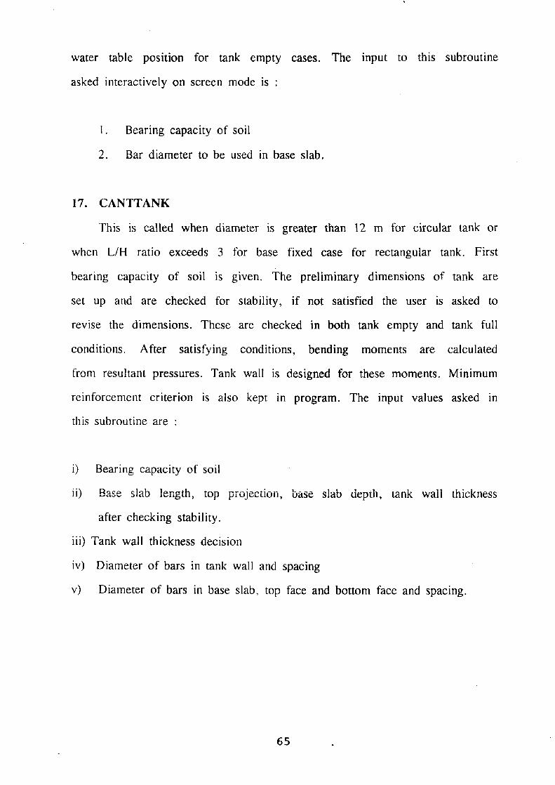
water table position for tank empty cases. The input to this subroutine
asked interactively on screen mode is :
1. Bearing capacity of soil
2. Bar diameter to be used in base slab.
17. CANTTANK
This is called when diameter is greater than 12 m for circular tank or
when L/H ratio exceeds 3 for base fixed case for rectangular tank. First
bearing capacity of soil is given. The preliminary dimensions of tank are
set up and are checked for stability, if not satisfied the user is asked to
revise the dimensions. These are checked in both tank empty and tank full
conditions. After satisfying conditions, bending moments are calculated
from resultant pressures. Tank wall is designed for these moments. Minimum
reinforcement criterion is also kept in program. The input values asked in
this subroutine are :
i) Bearing capacity of soil
ii) Base slab length, top projection, base slab depth, tank wail thickness
after checking stability.
iii) Tank wall thickness decision
iv) Diameter of bars in tank wall and spacing
v) Diameter of bars in base slab, top face and bottom face and spacing.
65

18. CALCULN
This is the main subroutine used in rectangular tank. In this various
subroutines called are given below :
TEMPT, TFULL, BIGN, THIC, SMAX, MINIMB, FSLAB, HGSLAB.
Input values required are -
* diameter of horizontal bars to be used at outer face
* diameter of horizontal bars to be used at inner face
* diameter of vertical bars to be provided at outer face
* diameter of vertical bars to be provided at inner face.
Various values of area of steel and spacing are printed out in output
file in tabular form.
The flow chart of this subroutine has been shown in Fig. 6.2.
19. CIRCULAR
This is used in circular tank in which various subroutines are called.
Various subroutines called are INTPOL, TEMPT, TFULL, STRESS, HOOPREIN,
MOMENT, HGSLAB, CFSLAB, CANTTANK. Inputvalues in this subroutine required
are :
* Capacity of tank in litres
* Code for height specified / diameter specified
* Height or diameter of tank
* Depth of tank below G.L.
* Ground water level below G.L.
66

* Unit weight of liquid filled
* Unit weight of soil
* Base condition code, fixed or hinged.
Flow chart of this subroutine has been shown in Fig.6.3.
6.2.3 Drafting of Designed Section
Drafting of rectangular tank has been dealt in this section. For
drafting three programs have been developed. Input of these programs in the
fileSHAKUN.DATwhich is created whenprogramCOMBIN.FOR is run. DRAFT1. FOR
is capable of generating three drawings of sectional elevation depending
upon the end conditions.
Program DRAFT2.FOR generates the sectional plan of the tank. Program
DRAFT3.FOR is for sectional elevation of tank wall when designed like
cantilever retaining wall.
Input values given on screen for these files are
* IOPORT and MODEL
* Window size
* Factor to enlarge or reduce the drawing
* Pen thickness for drawing
In these drawings colours have been used and give attractive coloured
drawings when output is taken on coloured plotter. Various IOPORT & MODEL
have been given in Table 6.1. Flow charts of DRAFTI.FOR and DRAFT2.FOR have
been shown in Fig. 6.4 and Fig. 6.5 respectively.

6.3 USER INTERFACE
Software development and its successful use for design depends upon
few important criteria which establish the desirable feature of process,
Interactive program has the option for only desired restriction on design
process, documentation ability to revise and case of redesign.
The interactive feature of software guides the user by providing
additional information such as unit of system to be used.
The program has been written to be user friendly and hence it is very
easy to use.
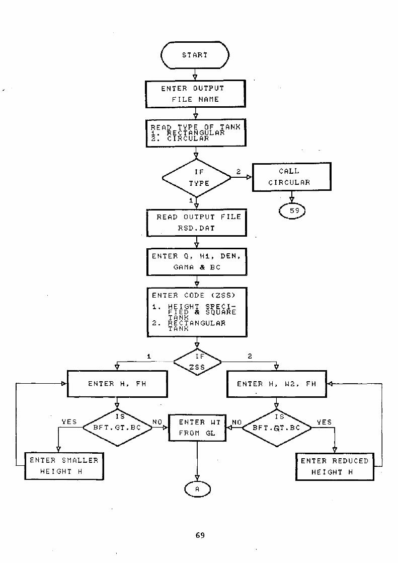
START
ENTER OUTPUT
FILE NAME
( READ TYPE OF TANK i. RECTANGULAR 2. CIRCULAR
IF 2 CALL
TYPE CIRCULAR
i
READ OUTPUT FIL 59
E
RSD.DAT
ENTER Q, Hi, DEN,
GAMA & BC
ENTER CODE (ZSS)
i. HEIGHT SPECI- FIED & SQUARE TANK
2. RECTANGULAR TANK
I F 2
S S
ENTER H, FH I I ENTER H, W2, FH
YES IS NO ENTER WT NO IS 'DES BFT.GT.BC
FROM GL BFT.GT.BC
ENTER SMALLER I I I ENTERGREDUCED HEIGHT H
r:
69

0
ENTER CODE(MCODE)
i. TOP FREE & BOTTOM FIXED
2. TOP FREE & BOTTOM HINGED
3. TOP & BOTTOM HINGED
IF i 2
MC0DE
9
/F IS Nd
L/H > 3 [LCINT
YES
CALL TEMPT
CALL STRESS
CALL CANTTANX
CALL CALCULN
59
STOP
END
FIG.6.1 — FLOW CHART OF GOMBIN.FOR
70
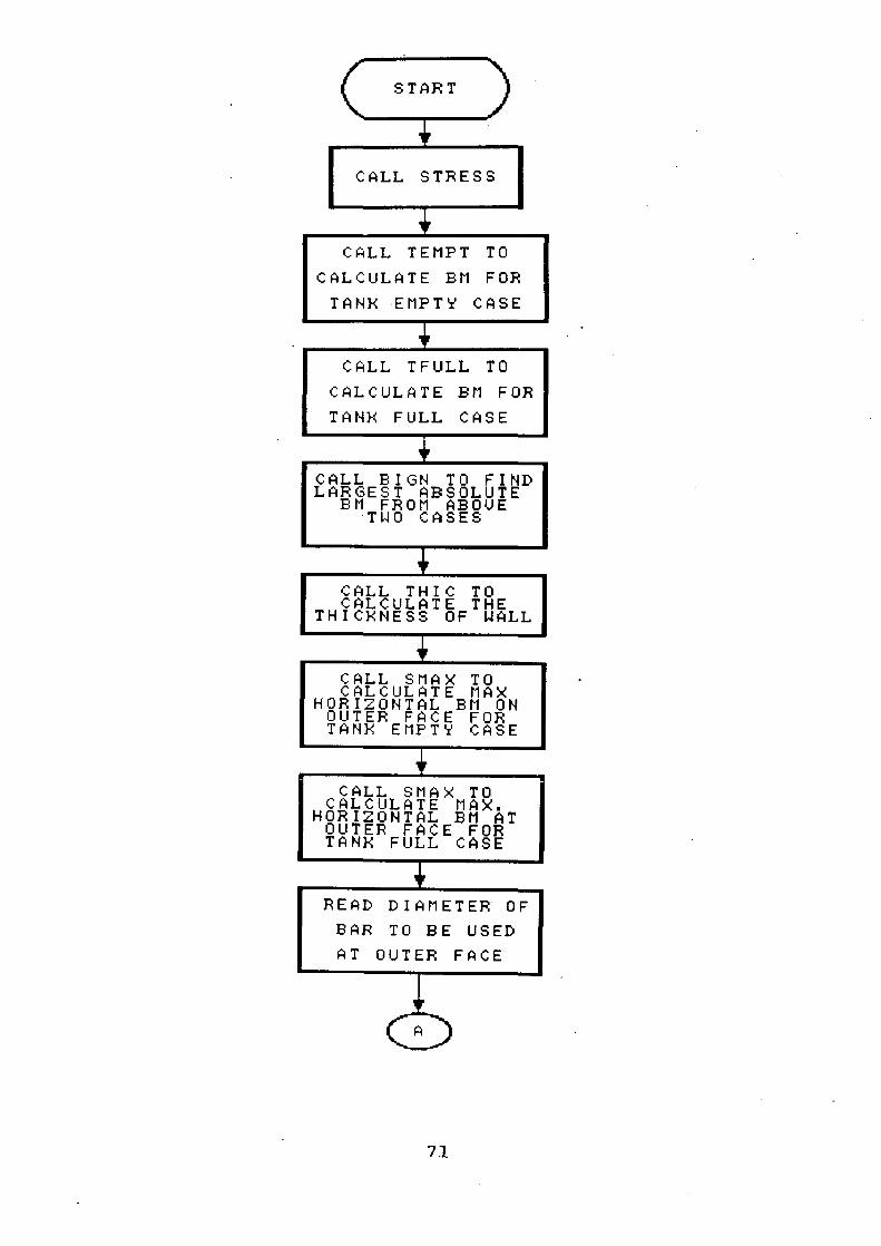
START
CALL STRESS
CALL TEMPT TO
CALCULATE BM FOR
TAN}< EMPTY CASE
CALL TFULL TO
CALCULATE BM FOR
TAN} 4 FULL CASE
CALL BIGN TO FIND LARGEST ABSOLUTE
BM FROM ABOVE TWO CASES
CALL THIC TO CALCULATE THE
THICKNESS OF WALL
CALL SMAX TO CALCULATE MAX
HORIZONTAL BM ON OUTER FACE FOR TANK EMPTY CASE
CALL SMAX TO CALCULATE MAX.
HORIZONTAL BM AT OUTER FACE FOR TANK FULL CASE
READ DIAMETER OF
BAR TO BE USED
AT OUTER FACE
Y
71

ri
CALL REINF TO CALCULATE AREA AND SPACING OF
HORIZONTAL STEEL AT OUTER FACE
READ SMALLER
DIAMETER OF BAR
r IS
SPAGO( i) >450MM READ LARGER
DIAMETER OF BAR
<450 MM I >i00 MM
CALL MINIBM TO CALCULATE MAX
HORIZONTAL BM AT INNER FACE FOR TANK FULL CASE
CALL MINIBM TO CALCULATE MAX
HORIZONTAL BM AT INNER FACE FOR TANX FULL CASE
READ DIA. OF BAR TO BE USED AT INNER FACE FOR HORIZONTAL
CALL REINF TO FIND AREA AND SPACING OF STEEL AT INNER FACE IN HORIZONTAL
DIRECTION
READ SMALLER
DIAMETER OF BAR
>450MM f IS
SPAGI ( i) <100MM READ LARGER
DIAMETER OF BAR
<450MM T>i00MM
CALL SMAX TO CALCULATE MAX VERTICAL EM AT OUTER FACE FOR TANK EMPTY CASE
B
72

0.3
CALL SMAX TO CALCULATE MAX VERTICAL BM AT OUTER FACE FOR TANK FULL CASE
READ DIA OF BAR TO BE USED AT OUTER FACE IN
VERTICAL DIRECTION
CALL REINFLi TO FIND AREA AND SPACING OF STEEL AT OUTER FACE IN VERTICAL
DIRECTION
READ SMALLER
DIAMETER OF BAR
Is >450MM
SPAGEi{ i)
<450111 T >i0011M
CALL MINIBM TO CALCULATE BM AT INNER CASE FOR TAN}< FULL CASE
CALL MINIBM TO CALCULATE BM AT INNER FACE FOR TANK FULL CASE
READ DIAMETER TO BE USED AT INNER FACE
C
< 100M t1 READ LARGER
DIAMETER OF BAR
73
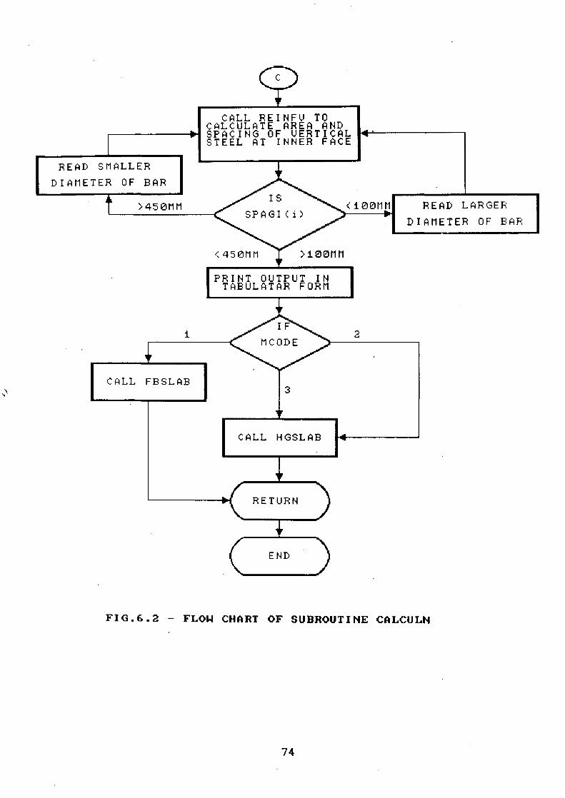
FIG.6.2 - FLOW CHART OF SUBROUTINE CALCULN
74
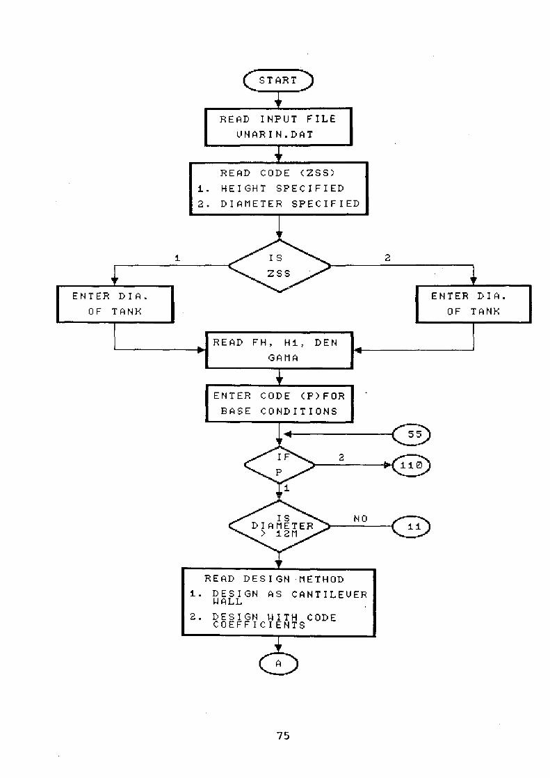
START
READ INPUT FILE
UNAR IN. DAT
READ CODE (ZSS)
i. HEIGHT SPECIFIED
2. DIAMETER SPECIFIED
i IS
2
2 S S
ENTER DIA. ENTER DIA.
OF TANX
OF TANX
READ FH, Hi, DEN
I LAMA
I ENTER CODE (F)FOR I BASE CONDITIONS
S5
IF 2 110
P
i
IS NO DIAMETER > 12M
ii
READ DESIGN METHOD
I. DESIGN AS CANTILEVER WALL
2. DESIGN WITH CODE COEFFICIENTS
0
75

IS CODE = 2
CODE
i OR 2
CODE = I
CALL TEMPT TO CALCULATE STATIC DYNAMIC PRESSURES
IN GIVEN CONDITION
CALL CANTTANE FOR DESIGN OF TANK AS CANTILEVER ILITY
CHECKING
GO TO 59
CALL INTPOL FOR INTERPOLATION OF
COEFFICIENTS FOR HOOP
TENSION FOR HzfDT CALCULATED
CALL INTPOL FOR INTERPOLATION OF MOMENT COEFFICIENTS FOR CALCULATED
H 2/DT
CALL TEMPT FOR ANALYSIS IN TAN1
EMPTY CASE AND GIVE HOOP COMPRESSION AND
MOMENTS
CALL TFULL FOR ANALYSIS IN TANK
FULL CASE AND GIVE HOOP TENSION AND
MOMENTS
B I
76

B
CALL STRESS TO GIVE OUT PERMISSIBLE STRESSES IN STEEL AND CONCRETE AND
EVALUATE LEVER ARM NEUTRAL AXIS DEPTH
CALL HOOPREIN TO CALCULATE HOOP
REINFORCEMENT ACCORDING TO TENSIONS CALCULATED
- IS - PERMISSIBLE
YES COMPRESSIVE
3 STRESS
EXCEEDED
CALL MOMENT TO CALCULATE VERTICAL
REINFORCEMENT IN TANK WALL
IF~ THICKNESS ASSIGNED INADEQUATE
YES 15
NO
CALL CFSLAB FOR DESIGN OF FIXED
BASE SLAB 59
110
CALL INTPOL FOR INTERPO-LATION OF COEFFICIENTS
OF HOOP TENSION IN HINGED BASE CONDITION
CALL INTPOL FOR INTERPOLATION OF COEFFICIENTS OF MOMENT IN HINGED BASE CONDITION
j
77
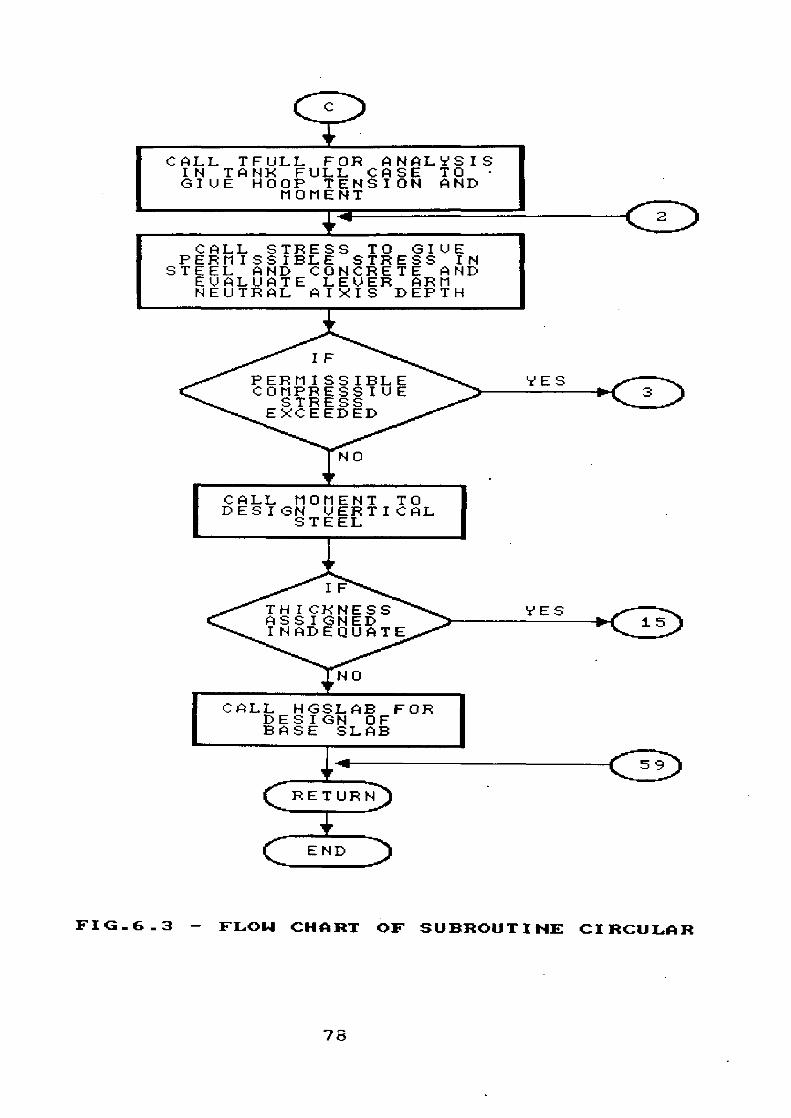
FIG_6_3 - FLOW CHART OF SUBROUTINE CIRCULAR
78

START
READ INPUT FILE
SHAXUN. DAT
ENTER IOPORT, MODEL
iPFACTOR,
2
3 MCODE
PLOT DRAWING FOR
PLOT DRAWING FOR TOP FREE BOTTOM
TOP & BOTTOM HINGED CASE
1
HINGED
I PLOT DRAWING FOR TOP FREE AND BOTTOM FIXED
STOP
END
FIG.6.4 - FLOW CHART OF DRAFTI.FOR
79

FIG.6.5 - FLOW CHART OF DRAFT2_FOR

Table -6.1: List of Devices Supported by Plot88
Pixel Density X Y
77 33
Device Name
IBM Color Graphix 99 Monitor CGA &.EGA Hercules Grahpics & Monochrom Monitor 99 (through Magic Key) Tektronix 4025 90 Epson Fx-80 0
1 2 3 4 5 6
Epson Fx-100 10 11 12 13 14 15 16
Epson Mx-80 0,1,2,3 IBM Printer 0,1,2,3 Epson Mx-100 10 to 13 HI-DMP-51 Plotter 51 HI-DV1P 52 Plotter 52 HP-7470A Plotter 20 HF-7475A Plotter 30
HP-7440A Drafting 80 Plotter
HP-7585B Drafting Plotter 85
Default Window Size
99
8.25"x6"
99 -
4800/4850 8.5"x8.75" 0 11"x8" 0 0 0 0 0 0 0 11"x13.6" 0 0 0 0 - 0 0 " 0 11"x8" 0 11"x8" 0 11"x13.6"
9600/9650 32.7"x21.5" 9600/9650 34.0x21.5" 9600/9650 10.7"x 7.5" 9600/9650 A 10.15x 7.8
B 16.3x10.15 A4 10.81x7.56 A3 15.82x10.81
9600/9650 32.2"x23.15
9600/9650 46.6 x34.6"
Codes MODEL IOPORT
75
75 72
60 72
120 72
120 72
240 72
80 72
72 72 -90 72
60 72
120 72
120 72
240 72
80 72
72 72
90
1000 1000 200 200
1016 1016 1016 1016 101.6 1016 10.16 1016 1016 1016 1016 1016
508 508
Th

CHAPTER 7
TEST EXAMPLES
The CADD package 'RCTANK' developed for analysis, design and
drafting of underground reinforced concrete tanks has been tested in
variety of conditions, which are being presented in this chapter. The test
examples involve problems with different base conditions and water table
position, to which program responds efficiently. Eight problems have been
presented here In first four problems, capacity of tank is 200 KL and in
remaining four problems, capacity of tank is 100KL. In these problems all
end conditions have been used to illustrate the functioning of software.
Test problems 4 & 8 are the cases when L/H ratio exceeds 3 and their design
like cantilever retaining wall is carried out. In these test problems
different depths of tanks in soil and water table positions has been used.
Grade of concrete and steel have also been varied. Drawings of these test
problems have been drawn using coloured plotter.
In test problem No. 5 and 6, uniform thickness has been taken to
illustrate its functioning.
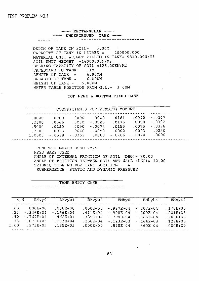
TEST PROBLEM NO.1
^-^-^-^- RECTANGULAR -^•^-- ^-~-^-^- UNDERGROUND TANK --- -
------------------------------------------
DEPTH OF TANK IN SOIL= 5.00M CAPACITY OF TANK IN LITRES = 200000.000 MATERIAL UNIT WEIGHT FILLED IN TANK= 9810.00N/M3 SOIL UNIT WEIGHT =16000.00N/M3 BEARING CAPACITY OF SOIL =125.00KN/M2 FREEBOARD TO TANK= .1M LENGTH OF TANK = 6.900M BREADTH OF TANK = 6.000M HEIGHT OF TANK = 5.000M WATER TABLE POSITION FROM G.L.= 1.00M
TOP FREE & BOTTOM FIXED CASE
COEFFICIENTS FOR BENDING MOMENT
.0000 .0000 .0000 .0000 .0181 .0040 -.0347
.2500 .0066 .0030 -.0080 .0176 .0060 -.0392
.5000 .0150 .0090 -.0075 .0155 .0075 -.0396
.7500 .0013 .0040 -.0050 .0002 .0003 -.0250 1.0000 -.0538 -.0362 .0000 -.0106 -.0070 .0000
CONCRETE GRADE USED =M25 HYSD BARS USED ANGLE OF INTERNAL FRICTION OF SOIL (DEG)= 30.00 ANGLE OF FRICTION BETWEEN SOIL AND WALL (DEG)= 10.00 SEISMIC ZONE NO.FOR TANK LOCATION = 4 SUBMERGENCE ,STATIC AND DYNAMIC PRESSURE
TANK EMPTY CASE -------------------------------------
x/H BMvyO BMvyb4 ----------------------------------------------------------------------
BMvyb2 BMhyO BMhyb4 BMhyb2
.00 .000E+00 .000E+00 .000E+00 -.927E+04 -.207E+04 .178E+05
.25 -.336E+04 -.156E+04 .411E+04 -.900E+04 -.309E+04 .201E+05
.50 -.769E+04 -.462E+04 .385E+04 -.794E+04 -.385E+04 .203E+05
.75 -.675E+03 -.203E+04 .256E+04 -.123E+03 -.164E+03 .128E+05 1.00 .275E+05 .185E+05 ----------------------------------------------------------------
.000E+00 .540E+04 .360E+04 .000E+00 ------
83

TANK FULL CASE ---------------------------------
X/H BMvyO BMvyb4 BMvyb2 ----------------------------------------------------------------------
BMhyO BMhyb4 BMhyb2
.00 .000E+00 .000E+00 .000E+00 .251E+05 .560E+04 -.481E+05
.25 .909E+04 .421E+04 -.111E+05 .244E+05 .837E+04 -.543E+05
.50 .208E+05 .125E+05 -.104E+05 .215E+05 .104E+05 -.549E+05
.75 .183E+04 .549E+04 -.693E+04 .333E+03 .443E+03 -.347E+05 1.00 -.745E+05 -.502E+05 .000E+00 ----------------------------------------------------------------------
-.146E+05 -.975E+04 .000E+00
LARGEST BM(N-m)= 74486.630 AT x/H=1.000
THICKNESS OF WALL FROM TOP TO 2.50M= 470.00mm THICKNESS OF WALL FROM 2.5M TO BOTTOM JUNCTION = 550 mm
HORIZONTAL REINFORCEMENT ***+------------------------------*****
DIAMETRE OF HORIZONTAL STEEL BAR AT OUTER FACE=16.00mm DIAMETRE OF HORIZONTAL STEEL BAR AT INNER FACE=16.00mm
HEIGHT VARIATION AREA OF STEEL AT SPACING OF REINFORCEMENT AT (IN METRE) (IN Sq.mm) (IN mm c/c)
FROM TO OUTER FACE -----
I INNER FACE ---------------------------- OUTER FACE I INNER FACE
.0 TO 1.9 1 940 ----------------------------------------------------------------------------
954 ( 210 210
1.9 TO 3.1 940 ----------------------------------------------------------------------------
964 210 205
3.1 TO 5.0 I 1100 ----------------------------------------------------------------------------
---------------------------------------------------------------------- 1100 I 180 180
------
***** *****
VERTICAL REINFORCEMENT *****----------------------------
DIAMETER OF VERTICAL STEEL BAR AT OUTER FACE=16.00mm
DIAMETER OF VERTICAL STEEL BAR AT INNER FACE=16.00mm
HEIGHT VARIATION AREA OF STEEL AT SPACING OF REINFORCEMENT AT (IN METRE) (IN Sq.mm) (IN mm c/c)
FROM TO OUTER FACE --------- ------
INNER FACE -------------- OUTER FACE INNER FACE
----------------------------------------------------------------------------
.0 TO 1.9 I 940 940 210 210
1.9 TO 3.1 940 940 210 210 ----------------------------------------------------------------------------
3.1 TO 5.0 1100 1100 180 180
84 ($(\%
•a,►

BASE SLAB DETAILS ------------------------------------
DIAMETER OF STEEL BAR USED IN BASE SLAB=12.00mm PROVIDE 75mm THICK CONCRETE LAYER OF GRADE M10 ON WELL RAMMED GROUND ON THAT PUT A BITUMEN OR EQUIVALENT MATERIAL LAYER.THEN ON THIS PROVIDE BASE SLAB. IF WIDTH OF TANK IS SMALL THEN THICKNESS EQUAL TO THICKNESS OF WALL IS PROVIDED IN WHOLE BASE SLAB ELSE EXTEND ATLEAST BY 1M IN BASE SLAB AND IN REST OF THE PORTION PROVIDE THICKNESS OF BASE SLAB =250.00mm. PROVIDE HAUNCH OF 150x150 mm AT WALL- SLAB JUNCTION WITH 8mm BARS @ 200mm c/c.
PROVIDE 12.0mm DIA BARS AT UPPER FACE OF BASE SLAB @ 170mm c/c WITH EFFECTIVE COVER OF 20mm IN BOTH DIRECTION AT RIGHT ANGLE.
PROVIDE12.Omm DIA BARS AT LOWER FACE OF BASE SLAB @ 170mm c/c WITH EFFECTIVE COVER OF 20mm IN BOTH DIRECTION AT RIGHT ANGLE.-

4{70mm 0.011 + + __ _ 0.0M
h91 16 t Ola 6trc 0 2101 c/c
16 mm Lila Bars n 210mm c/c
16 mm Ilia Bars o 210mm c/c+__4fl16 0 Dia Sara 0 210c , o/c
?. i T 1.9M
2.5(4 ;• r 16 mm Ola Bars c 210 ta/c p I E
16 rxa Ola Banc a 210 c~a c!c _ ft 16 cca Dia Sara 0 205i a/c 5.00 M 16 mm Dia Bars a 210mm c/c N 3.111
--_550mm
3.7 M 16 mm Ola Bars a 180 mm c/c
16 mm Ola Bars o 1B0 mm c/c
,. 16 DYa Bars m 160 c a c/c 16 Oat Bam 0 180 c/c 8 mm 0 i s Bars o 200 aim c/c f
15OXISOMM HAUNCH --1-► i f E
S.OF~ ' #• 5.011 A
~s. .. 2.orim En1arijcd In Vortical Oirccticn
\ 12 c= Ola Sara 0 17Q a/c T P FREE 61JTT6?4 FIXED ~ 12 mm 01 a Bars d 170 mm c/c
SECTIONAL ELEVATION

,~.,.~......~ 16 a Dia Bars $ l83 mm c/c 36 mm Da Sara a 18O nm c/c
'
zils DLa aaro ® 1BD c/a
16 mm Dia Ber. $ 18©~e ola
16 mm D is Sara a 18D mm c/c
16 D!a bars o 180.x. */a
6 Dig 8*r* a 1e0,tim c/0
: : i : _____
6.9O M
SECTIONAL PLAN * °`T'~
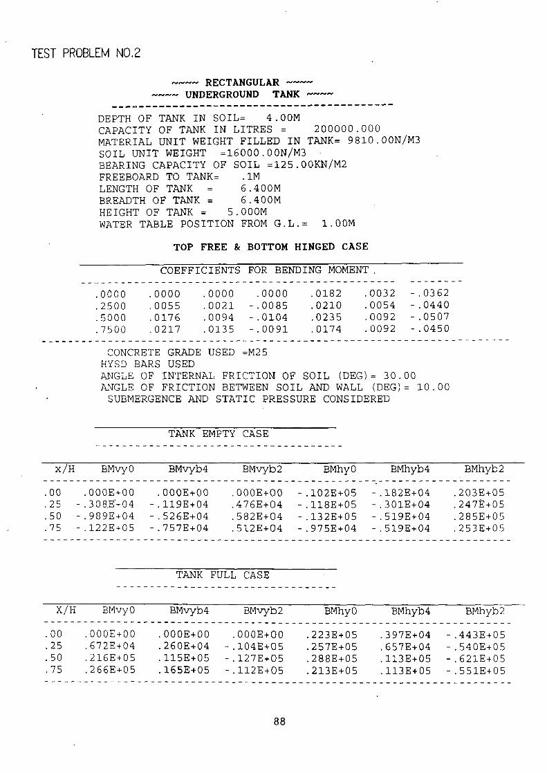
TEST PROBLEM NO.2
---- RECTANGULAR ---- ~^-^-^- UNDERGROUND TANK ----
DEPTH OF TANK IN SOIL= 4.00M CAPACITY OF TANK IN LITRES = 200000.000 MATERIAL UNIT WEIGHT FILLED IN TANK= 9810.00N/M3 SOIL UNIT WEIGHT =16000.00N/M3 BEARING CAPACITY OF SOIL =125.00KN/M2 FREEBOARD TO TANK= .1M LENGTH OF TANK = 6.400M BREADTH OF TANK = 6.400M HEIGHT OF TANK = 5.000M WATER TABLE POSITION FROM G.L.= 1.00M
TOP FREE & BOTTOM HINGED CASE
COEFFICIENTS FOR BENDING MOMENT. ------ - -------
.0000
----------------------------------------- .0000 .0000 .0000 .0182 .0032 -.0362
.2500 .0055 .0021 -.0085 .0210 .0054 -.0440
.5000 .0176 .0094 -.0104 .0235 .0092 -.0507
.7500 .0217 .0135 -.0091 .0174 .0092 -.0450
CONCRETE GRADE USED =M25 HYSD BARS USED ANGLE OF INTERNAL FRICTION OF SOIL (DEG)= 30.00 ANGLE OF FRICTION BETWEEN SOIL AND WALL (DEG)= 10.00 SUBMERGENCE AND STATIC PRESSURE CONSIDERED
TANK EMPTY CASE
x/H BMvyO BMvyb4 BMvyb2 BMhyO BMhyb4 BMhyb2
.00 .000E+00 .000E+00 .000E+00 -.102E+05 -.182E+04 .203E+05
.25 -.308,E+04 -.119E+04 .476E+04 -.118E+05 -.301E+04 .247E+05
.50 -.989E+04 -.526E+04 .582E+04 -.132E+05 -.519E+04 .285E+05
.75 -.122E+05 -.757E+04 ----------------------------------------------------------------
.512E+04 -.975E+04 -.519E+04 .253E+05 ------
TANK FULL CASE ---------------------------------
X/H BMvyO BMvyb4 -----------------------------------------------------------------------
BMvyb2 BMhyO BMhyb4 BMhyb2
.00 .000E+00 .000E+00 .000E+00 .223E+05 .397E+04 -.443E+05
.25 .672E+04 .260E+04 -.104E+05 .257E+05 .657E+04 -.540E+05
.50 .216E+05 .115E+05 -.127E+05 .288E+05 .113E+05 -.621E+05
.75 .266E+05 .165E+05 ----------------------------------------------------------------
-.112E+05 .213E+05 .113E+05 -.551E+05 ------

16 mm Die Bars a 195m c/c 16 mm Die Bars a 195 mm c/c
•
ZI mmOiaBarso 19Smma/c •
16 mmDiaBar*a i9Swuec/c .
Co . 16 mm Dia Bat. o i9S mm c/c
16 mm Dia Bare a i95mm c/c 16 m Dia Bars a l9Smm c/c
.
6.410 M
SECTIONRL PLAN * NT TO SCALE
r
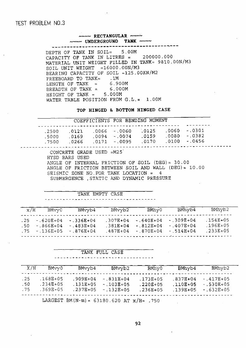
TEST PROBLEM NO.3
---- RECTANGULAR --- ---- UNDERGROUND TANK NNNN
DEPTH OF TANK IN SOIL= 5.00M CAPACITY OF TANK IN LITRES = 200000.000 MATERIAL UNIT WEIGHT FILLED IN TANK= 9810.00N/M3 SOIL UNIT WEIGHT =16000.00N/M3 BEARING CAPACITY OF SOIL =125.00KN/M2 FREEBOARD TO TANK= .1M LENGTH OF TANK = 6.900M BREADTH OF TANK = 6.000M HEIGHT OF TANK = 5.000M WATER TABLE POSITION FROM G.L.= 1.00M
TOP HINGED & BOTTOM HINGED CASE
COEFFICIENTS FOR BENDING MOMENT ----------------------------------------------- -------- .2500 .0121 .0066 -.0060 .0125 .0060 -.0301 .5000 .0169 .0094 -.0074 .0159 .0080 -.0382 .7500 .0266 .0171 -.0095 .0170 .0100 -.0456
----------------------------------------------------------------------
CONCRETE GRADE USED =M25 HYSD BARS USED ANGLE OF INTERNAL FRICTION OF SOIL (DEG)= 30.00 ANGLE OF FRICTION BETWEEN SOIL AND WALL (DEG)= 10.00 SEISMIC ZONE NO.FOR TANK LOCATION = 4 SUBMERGENCE ,STATIC AND DYNAMIC PRESSURE
TANK EMPTY CASE
x/H BMvyO BMvyb4 BMvyb2 ----------------------------------------------------------------------
BMhyO BMhyb4 BMhyb2
.25 -.620E+04 -.336E+04 .307E+04 -.640E+04 -.309E+04 .154E+05
.50 -.866E+04 -.483E+04 .381E+04 -.$12E+04 -.407E+04 .196E+05
.75 -.136E+05 -------------------------------------------------
-.876E+04 .487E+04 -.870E+04 -.514E+04 =--------------
.233E+05 ------
TANK FULL CASE ---------------------------------
x/H BMvyO BMvyb4 BMvyb2 BMhyO BMhyb4 BMhyb2
.25 .168E+05 .909E+04 -.831E+04 .173E+05 .837E+04 -.417E+05
.50 .234E+05 .131E+05 -.103E+05 .220E+05 .110E+05 -.530E+05
.75 .369E+0.5 .237E+05 -.132E+05 .236E+05 .139E+05 -.632E+05
LARGEST BM(N-m)= 63180.620 ----------------------------------------------------------------------
AT x/H= .750
92

THICKNESS OF WALL FROM TOP TO 2.50M= 470.00mm THICKNESS OF WALL FROM DEPTH (= 2.50M)TO BOTTOM JUNCTION= 510.00mm
***** ***** HORIZONTAL REINFORCEMENT
*****------------------------------*****
DIAMETRE OF HORIZONTAL STEEL BAR AT OUTER FACE=16.00mm
DIAMETRE OF HORIZONTAL STEEL BAR AT INNER FACE=16.00mm
HEIGHT VARIATION AREA OF STEEL AT SPACING OF REINFORCEMENT AT (IN METRE) (IN Sq.mm) (IN mm c/c)
---------------- FROM TO
------------------------ OUTER FACE I INNER FACE
-- OUTER FACE I INNER FACE
---------------------------------------------------------------------------
.0 TO 1.9 1 940 940 I 210 210 -
------------------------------------------------------ ---------------------
1.9 TO 3.1 940 940 1 210 210 ------------------------------------------------------ ---------------------
3.1 TO 5.0 1020 1020 ' 195 195 ------------------------------------------------------ ---------------------
***** ***** VERTICAL REINFORCEMENT
*****----------------------------*****
DIAMETER OF VERTICAL STEEL BAR AT OUTER FACE=16.00mm
DIAMETER OF VERTICAL STEEL BARAT INNER FACE=16.00mm
HEIGHT VARIATION AREA OF STEEL AT SPACING OF REINFORCEMENT AT (IN METRE) (IN Sq.mm) (IN mm c/c)
FROM TO OUTER FACE INNER FACE OUTER FACE INNER FACE
4 .0 TO 1.9 1 940 ----------------------------------------------------------------------------
940 1 ----------------------------------------------------------------------------
210 210
1.9 TO 3.1 940 940 I 210 210 1
3.1 TO 5.0 1 -------------------------------------------------------------------
1020 1020 I 195 195 ------ --
BASE SLAB DETAILS ------------------------------------
DIAMETER OF STEEL BAR USED IN BASE SLAB=12.00mm PROVIDE 75mm THICK CONCRETE LAYER OF GRADE M10 ON WELL RAMMED GROUND
ON THAT PUT A BITUMEN OR EQUIVALENT MATERIAL LAYER. THEN ON THIS PROV-IDE BASE SLAB.
THICKNESS OF BASE SLAB=200.00mm PROVIDE 12.0mm DIA BARS @ 360.00mm c/c BOTHWAYS AT TOP AND BOTTOM
FACE OF BASE SLAB IN BOTH DIRECTIONS AT RIGHT ANGLE
93

0.01 ~lb [ii 0.011
16 mm Dia Bare 0210mmc/c
16 mm Ola Bars 0 210mm c/c
470 mm ,.16 mm Dia Bare 0 210mm c/c
16 ms Ella Bars a 210mm c/c
1.9$
2.SM
16 mm Ella Bar. o195mmc/c
16 mm Ella Bare o195smc/c
3.7M- 16 mm Dia Bars o 195mm c/c
16 mm 01* Bars 0 195 a m c/c
5.0M
16om Ella Bare aIssm0/0
16 mm Dia Bars 0 195mm c/c 3.111
510mm
16 am Ella Bare a195amnc/c
16 mm Ella Bare a195mmc/c
5.011 200 mm
5.00 M
E- 1.8Times Enlarged in Vertical Direction
12 mm Dia Bars a 350 a/c * TOP RHO BBTTOM HINGED 12 mm 01* Bars o 360 mm o/c
SECTIONRL ELEVRTION
94

TEST PROBLEM .NO. 4
NNNM RECTANGULAR ~~~N --^-^- UNDERGROUND TANK - ---
------------------------------------------ DEPTH OF TANK IN SOIL= 4.00M CAPACITY OF TANK IN LITRES = 200000.000 MATERIAL UNIT WEIGHT FILLED IN TANK= 9810.00N/M3 SOIL UNIT WEIGHT =16000.00N/M3 BEARING CAPACITY OF SOIL =125.00KN/M2 FREEBOARD TO TANK= .1M LENGTH OF TANK = 12.900M BREADTH OF TANK = 4.000M HEIGHT OF TANK = 4.000M WATER TABLE POSITION FROM G.L.= 6.00M ANGLE OF INTERNAL FRICTION OF SOIL (DEG)= 30.00 ANGLE OF FRICTION BETWEEN SOIL AND WALL (DEG)= 10.00 SEISMIC ZONE NO.FOR TANK LOCATION = 3 STATIC AND DYNAMIC PRESSURE CONSIDERED CONCRETE GRADE USED =M25 HYSD BARS USED
***************************************
DESIGN OF TANK AS CANTILIVER
STEM WALL DETAILS
THICKNESS(M)= .30 REDUCED TO 20CM AT TOP
WATER FACE REINFORCEMENT (FROM TOP) IN STEM
REINFORCEMENT BARDIA SPACING C/C FROM TO (M) (MM) (MM)
.00 2.10 20.00 240.•00
2.10 4.00 20.00 120.00 EARTH FACE REINFORCEMENT (FROM TOP) IN STEM --------------------------------------------
REINFORCEMENT BARDIA SPACING C/C FROM TO (M) (MM) (MM)
.00 2.10 16.00 320.00
2.10 4.00 16.00 160.00 DISTRIBUTION REINFORCEMENT ON EACH FACE
-------------------------------------------- BARDIA SPACING 12.00 300.00
BASE SLAB DETAILS ------------------------------------
THICKNESS OF BASE SLAB= .30 TOE SLAB LENGTH= 1.00 HEEL SLAB LENGTH= 2.50
96

HEEL REINFORCEMENT DETAILS
TOP FACE
BARDIA SPACING 20.00 175.00
BOTTOM FACE
BARDIA SPACING 20.00 330.00
DISTRIBUTION REINFORCEMENT ON EACH FACE BARDIA SPACING 12.00 300.00
TOE REINFORCEMENT DETAILS - ----- ---------------------
TOP FACE
BARDIA SPACING 20.00 175.00
BOTTOM FACE
BARDIA SPACING 20.00 120.00
DISTRIBUTION BARS ON EACH FACE BARDIA SPACING 12.00 300.00
PROVIDE CONSTRUCTION JOINT AT BASE. DIAMETER OF STEEL BAR USED IN BASE SLAB=12.00mm
PROVIDE 75mm THICK CONCRETE LAYER OF GRADE M10 ON WELL RAMMED GROUND ON THAT PUT A BITUMEN OR EQUIVALENT MATERIAL LAYER. THEN ON THIS PROV-IDE BASE SLAB.
THICKNESS OF BASE SLAB=200.00mm PROVIDE 12.Omm DIA BARS @ 360.00mm c/c BOTHWAYS AT TOP AND BOTTOM
FACE OF BASE SLAB IN BOTH DIRECTIONS AT RIGHT ANGLE
97

200
f
2. IM t dta bets • 2440 t.a a/c
16 am dia br4ry a 320 mm a/c 12 s dla barc m Stan c/a
4.t ! WATER FACE 20 a dia bar x 6 120 a o%
12 c, d1a bam a 300 am a/c
16 s diabara* - 160 c/c
20 + dla barn v 175 = o% _.
12 m dta bare ® SQ °/ 000
12 r dia bars 0 300 r a/c .300 acs 20 cm dia barn ® 175 c/c .26m=
20 a= dia barn o 120 m c! 20 as dia barn a 330= a/c
HO• T13 5CFLE
SECTIONAL ELEVATION

12 mm Dia Bars a 300mm o%
16 mm Oil Bars a lSOmm a/c
j I
Z20mm0iaBarsa 120 mc%
12 mm 01a Bars S 160emm c/c
. . H
• __ ___. _ 12 ro oia Bars o 900em c/c
• 20 mm 01a Bar a 12Omm c/c I • 12 mm 01a Bars O 300 mm cilc ~•
11°iT i iiii5
0
SECTIONAL. PLAN * NtT3aLE

TEST PROBLEM NO. 5
---- RECTANGULAR NNN/V
---- UNDERGROUND TANK --NN
DEPTH OF TANK IN SOIL= 4.00M CAPACITY OF TANK IN LITRES = 100000.000 MATERIAL UNIT WEIGHT FILLED IN TANK= 9810.00N/M3 SOIL UNIT WEIGHT =16000.00N/M3 BEARING CAPACITY OF SOIL =125.00KN/M2 FREEBOARD TO TANK= .1M LENGTH OF TANK = 5,10014 BREADTH OF TANK = 5.10014 HEIGHT OF TANK = 4.000M WATER TABLE POSITION FROM G.L.= 1.00M
TOP FREE & BOTTOM FIXED CASE
COEFFICIENTS FOR BENDING MOMENT
.0000 .0000 .0000 .0000 .0156 .0032 -.0301
.2500 .0053 .0022 -.0072 .0155 .0052 -.0350 5000 .0142 .0082 -.0071 .0151 .0071 -.0375 .7500 .0051 .0048 -.0050 .0057 .0041 -.0242
1.0000 -.0483 -.0320 ----------------------------------------------------------------
.0000 -.0093 -.0062 .000.0 ------
CONCRETE GRADE USED =M20 HYSD BARS USED
ANGLE OF INTERNAL FRICTION OF SOIL (DEG)= 30.00 ANGLE OF FRICTION BETWEEN SOIL AND WALL (DEG)= 10.00 SUBMERGENCE AND STATIC PRESSURE CONSIDERED
TANK EMPTY CASE
x/H BMvyO BMvyb4 ----------------------------------------------------------------------
BMvyb2 BMhyO BMhyb4 BMhyb2
.00 .000E+00 .000E+00 .000E+00 -.394E+04 -.809E+03 .761E+04
.25 -.134E+04 -.556E+03 .182E+04 -.392E+04 -.131E+04 .885E+04
.50 -.359E+04 -.207E+04 .179E+04 -.382E+04 -.179E+04 .948E+04
.75 -.129E+04 -.121E+04 .126E+04 -.144E+04 -..104E+04 .612E+04 1.00 .122E+05 .809E+04 ----------------------------------------------------------------
.000E+00 .235E+04 .157E+04 .000E+00 ------
100

TANK FULL CASE ---------------------------------
X/H BMvyO BMvyb4 BMvyb2 BMhyO BMhyb4 BMhyb2
.00 .000E+00 .000E+00 .000E+00 .979E+04 .201E+04 -.189E+05
.25 .333E+04 .138E+04 -.452E+04 .973E+04 .326E+04 -.220E+05
.50 .892E+04 .515E+04 -.446E+04 .948E+04 .446E+04 -.235E+05
.75 .320E+04 .301E+04 -.314E+04 .358E+04 .257E+04 -.152E+05
1.00 - .303E+05 -.201E+05 .000E+00 -.584E+04 -.389E+04 .000E+00
LARGEST BM(N-m)= 30324.670 ----------------------------------------------------------------------
AT x/H=1.000 UNIFORM THICKNESS OF WALL FROM TOP TO BOTTOM JUNCTION= 365.00mm
***** *****
HORIZONTAL REINFORCEMENT *****-------------•------------------*****
DIAMETRE OF HORIZONTAL STEEL BAR AT OUTER FACE=16.00mm
DIAMETRE OF HORIZONTAL STEEL BAR AT INNER FACE=16.00mm
HEIGHT VARIATION AREA OF STEEL AT SPACING OF REINFORCEMENT AT (IN METRE) (IN Sq.mm) (IN mm c/c)
FROM I - TO OUTER FACE I INNER FACE OUTER FACE I INNER FACE
1 .0 TO 1.5 1 818 818 1 245 245 1 ----------------------------------------------------------------------------
1.5 TO 2.5 818 818 I 245 245 ----------------------------------------------------------------------------
2.5 TO 4.0 I 818 818 1 245 245 ----------------------------------------------------------------------------
***** *****
VERTICAL REINFORCEMENT +****----------------------------*****
DIAMETER OF VERTICAL STEEL BAR AT OUTER FACE=16.00mm
DIAMETER OF VERTICAL STEEL BAR AT INNER FACE=12.00mm
HEIGHT VARIATION AREA OF STEEL AT SPACING OF REINFORCEMENT AT (IN METRE) (IN Sq.mm) (IN mm c/c)
FROM TO OUTER FACE INNER FACE OUTER FACE I INNER FACE
1 .0 TO 1.5 I 818 ----------------------------------------------------------------------------
818 1 245 135
1 1.5 TO 2.5 818 ----------------------------------------------------------------------------
818 245 135
2.5 TO 4.0 818 ----------------------------------------------------------------------------
----------------------------------------------------------------------- 818 J 245 135
------
101

BASE SLAB DETAILS ------------------------------------
DIAMETER OF STEEL BAR USED IN BASE SLAB=12.00mm PROVIDE 75mm THICK CONCRETE LAYER OF GRADE M10 ON WELL RAMMED GROUND ON THAT PUT A BITUMEN OR EQUIVALENT MATERIAL LAYER.THEN ON THIS PROVIDE BASE SLAB. IF WIDTH OF TANK IS SMALL THEN THICKNESS EQUAL TO THICKNESS OF WALL IS PROVIDED IN WHOLE BASE SLAB ELSE EXTEND ATLEAST BY 1M IN BASE SLAB AND IN REST OF THE PORTION PROVIDE THICKNESS OF BASE SLAB =200.00mm. PROVIDE HAUNCH OF 150x150 mm AT WALL- SLAB JUNCTION WITH 8mm BARS @ 200mm c/c.
PROVIDE 12.Omm DIA BARS AT UPPER FACE OF BASE SLAB @ 200mm c/c WITH EFFECTIVE COVER OF 20mm IN BOTH DIRECTION AT RIGHT ANGLE.
PROVIDE12.Omm DIA BARS AT LOWER FACE OF BASE SLAB @ 200mm c/c WITH EFFECTIVE COVER OF 20mm IN BOTH DIRECTION AT RIGHT ANGLE.
102

O.OM
16 amDiaBaro02i&5r c%
12 a Dia 8arc v 21&5 rasa c/c
2.511
12 = DIa Bara ® 21t5nc c/c
16emDia88ro8245c+c/c
o. OM
16 C=otaswoa135tac/c
16 Ula Brzi C) 2l1S.. c/c
1.SM
16= maBaroa135=*/0
16 CaD1aBw-a02l15c c/c 11.00N
1.SM
2.511
12 DIaBarsm21&51ac/c
16 01a Bart a 2!S a a/c
8 ca Oia 8aro m 200t ► c/a t5OX150z HRUNCH 4
tL0i1 /
16 aOIal®135moc/c
16 DiaBarom2uS=ac/c
E 2.5 TI oa Enlaced in Vortical Diroctian
12 = Ota 6aro a 20Dm a/c * THE' FREE BUTT1 FIXED 12 rya Dia Barn ® 200oo c/c
SECTIONAL ELEVATION
103

TEST PROBLEM NO. 6
---- RECTANGULAR ---- ---- UNDERGROUND TANK ----
DEPTH OF TANK IN SOIL= 4.00M CAPACITY OF TANK IN LITRES = 100000.000 MATERIAL UNIT WEIGHT FILLED IN TANK= 9810.00N/M3 SOIL UNIT WEIGHT =16000.00N/M3 BEARING CAPACITY OF SOIL =125.00KN/M2 FREEBOARD TO TANK= .1M LENGTH OF TANK = 5.800M BREADTH OF TANK = 4.500M HEIGHT OF TANK = 4.000M WATER TABLE POSITION FROM G.L.= 3'.00M
TOP FREE & BOTTOM HINGED CASE
COEFFICIENTS FOR BENDING MOMENT
.0000 -----------------------------------------
.0000 .0000 .0000 ------
.0250 .0046 -------- -.0484
.2500 .0082 .0028 -.0112 .0.264 .0074 -.0556
.5000 .0210 .0114 -.0124 .0262 .0106 -.0602
.7500 .0258 .0162 -.0098 .0194 .0106 -.0504
CONCRETE GRADE USED ----------------------------------------------------------------------
=M20 HYSD BARS USED ANGLE OF INTERNAL FRICTION OF SOIL (DEG)= 30.00 ANGLE OF FRICTION BETWEEN SOIL AND WALL (DEG)= 10.00 SUBMERGENCE AND STATIC PRESSURE CONSIDERED
TANK EMPTY CASE
x/H BMvyO BMvyb4 ----------------------------------------------------------------------
BMvyb2 BMhyO BMhyb4 BMhyb2
.00 .000E+00 .000E+00 .000E+00 .113E+04 .209E+03 -.219E+04
.25 .372E+03 .127E+03 -.508E+03 .120E+04 .336E+03 -.252E+04
.50 .952E+03 .517E+03 -.562E+03 .119E+04 .481E+03 -.273E+04
.75 .117E+04 .735E+03 ----------------------------------------------------------------
-.444E+03 .880E+03 .481E+03 -.229E+04 ------
TANK FULL CASE ---------------------------------
X/H BMvyO BMvyb4 ----------------------------------------------------------------------
BMvyb2 BMhyO BMhyb4 BMhyb2
.00 .000E+00 .000E+00 .000E+00 .157E+05 ..289E+04 -.304E+05
.25 .515E+04 .176E+04 -.703E+04 .166E+05 .465E+04 -.349E+05
.50 .132E+05 .716E+04 -.779E+04 .164E+05 .666E+04 -.378E+05
.75 .162E+05 .102E+05 -.615E+04 .122E+05 .666E+04 -.316E+05
105

LARGEST BM(N-m)= 37795.970 AT x/H= .500 UNIFORM THICKNESS OF WALL FROM TOP TO BOTTOM JUNCTION= 400.00mm
*****.
HORIZONTAL REINFORCEMENT *****------------------------------*****
DIAMETRE OF HORIZONTAL STEEL BAR AT OUTER FACE=16.00mm
DIAMETRE OF HORIZONTAL STEEL BAR AT INNER FACE=16.00mm
HEIGHT VARIATION AREA OF STEEL AT SPACING OF REINFORCEMENT AT (IN METRE) (IN'Sq.mm) (IN mm c/c)
FROM I TO OUTER FACE INNER FACE OUTER FACE I INNER FACE ----------------------------------------------------------------------------
.0 TO 1.5 1 857 857 ( 230 230 ----------------------------------------------------------------------------
1.5 TO 2.5 I 857 857 ( 230 230
2.5 TO 4.0 857 857 I 230 230 ----------------------------------------------------------------------------
***** *****
VERTICAL REINFORCEMENT *****----------------------------*****
DIAMETER OF VERTICAL STEEL BAR AT OUTER FACE=16.00mm
DIAMETER OF VERTICAL STEEL BAR AT INNER FACE=16.00mm
HEIGHT VARIATION AREA OF STEEL AT SPACING OF REINFORCEMENT AT (IN METRE) (IN Sq.mm) (IN mm c/c)
FROM TO OUTER FACE INNER FACE OUTER FACE INNER FACE
.0 TO 1.5 857 -----------------------------------------------------------------------------
857 230 230 ------ -----
1.5 TO 2.5 ----------------------------------------------------------------
857 ----------------------------------------------------------------------------
857 230 230 1
2.5 TO 4.0 1 857 857 I - 230 230
BASE SLAB DETAILS ------------------------------------
DIAMETER OF STEEL BAR USED IN BASE SLAB=12.00mm PROVIDE 75mm THICK CONCRETE LAYER OF GRADE M10 ON WELL RAMMED GROUND
ON THAT PUT A BITUMEN OR EQUIVALENT MATERIAL LAYER. THEN ON THIS PROV-IDE BASE SLAB.
THICKNESS OF BASE SLAB=200.00mm PROVIDE 12.Omm DIA BARS @ 360.00mm c/c BOTHWAYS AT TOP AND BOTTOM
FACE OF BASE SLAB IN BOTH DIRECTIONS AT RIGHT ANGLE
106

0.0 P1
16 mm
DiaSara 0 230mm m a/c
16 m Dia Bwo a 230mm c/c
2.511
0.011
16 mm Dia Bars a 230mm c/c
16 mm Dia Ba-o a 230mm a/c
1.511
16 co Dia Sara a 230mm o% 16 cm Dia Barra a 230 ca 0/0
16 m Oia Sara a 230mm c/c
1.511
16 m Dia. Kara a 230mm c/c 16 mm DIa Sara 0 230mm c/c
l&. ON
16 me DiaSara 0 230mm c% 2.511
16mDiaBarc025mrac/c
16 mm Dia BQrc a 230mm a/c
I .0P1
200 mm 2.2Timoa Enlarged In
Vortical Diroction
- -12 mm Dia Bare a 960rnm o/c * TOP FREE 88TTQM HINGEO 12 mm Dia Bury a 360m c/c
SECTIONRL ELEVATION
,07

0
16 mm Dia Bars 5 230mm a/c
I6 can Da B&rs o 230m, c/c
. Z I16 = Ola Bar* o 230mmc/c •
I6 mm Dia Bata o 230 mm c/c •
I6 mm Da Bars 0 230 mm c/c
S
.
16 mmDiaBa*o 230mmc% ' 1/o •
. . . • . • . . . . . . S
SECTI©NRL PLAN * '1T

TEST PROBLEM NO. 7
NNNN RECTANGULAR NNNN
-- UNDERGROUND TANK NNA/N
------------------------------------------
DEPTH OF TANK IN SOIL= 4.00M CAPACITY OF TANK IN LITiZES = 100000.000 MATERIAL UNIT WEIGHT FILLED IN TANK= 9810.00N/M3 SOIL UNIT WEIGHT =16000.00N/M3 BEARING CAPACITY OF SOIL =125.00KN/M2 FREEBOARD TO TANK= .1M LENGTH OF TANK = 5.000M BREADTH OF TANK = 5.000M HEIGHT OF TANK = 4.000M WATER TABLE POSITION FROM G.L.= 1.00M
TOP HINGED & BOTTOM HINGED CASE
COEFFICIENTS FOR BENDING MOMENT ----------------------------------------------- -------- .2500 .0090 .0050 -.0060 .0120 .0050 -.0280 .5000 .0190 .0110 -.0090 .0190 .0090 -.0450 .7500 .0230 .0140 -.0090 .0170 .0090 -.0430
---------------------------------------------------------------------- CONCRETE GRADE USED =M20
MILD STEEL BARS USED ANGLE OF INTERNAL FRICTION OF SOIL (DEG)= 30.00 ANGLE OF FRICTION BETWEEN SOIL AND WALL (DEG)= 10.00 SEISMIC ZONE NO.FOR TANK LOCATION = 4 SUBMERGENCE ,STATIC AND DYNAMIC PRESSURE
TANK EMPTY CASE -------------------------------------
x/H BMvyO BMvyb4 BMvyb2 BMhyO BMhyb4 BMhyb2
.25 -.205E+04 -.114E+04 .137E+04 -.273E+04 -.114E+04 .637E+04
.50 -.432E+04 -.250E+04 .205E+04 -.432E+04 -.205E+04 .102E+05
.75 -.523E+04 -.319E+04 ----------------------------------------------------------------
.205E+04 -.387E+04 -.205E+04 .978E+04 ------
TANK FULL CASE
X/H BMvyO BMvyb4 ----------------------------------------------------------------------
BMvyb2 BMhyO BMhyb4 BMhyb2
.25 .638E+04 .355E+04 -.426E+04 .851E+04 .355E+04 -.199E+05
.50 .135E+05 .780E+04 -.638E+04 .135E+05 .638E+04 -.319E+05
.75 .163E+05 .993E+04 -.638E+04 .121E+05 .638E+04 -.305E+05
LARGEST BM(N-m)= 31922.840 AT x/H= .500
109

THICKNESS OF WALL FROM TOP TO 1.00M= 200.00mm THICKNESS OF WALL FROM DEPTH (= 1.00M)TO BOTTOM JUNCTION= 370.00mm
HORIZONTAL REINFORCEMENT *****------------------------------*****
DIAMETRE OF HORIZONTAL STEEL BAR AT OUTER FACE=16.00mm
DIAMETRE OF HORIZONTAL STEEL BAR AT INNER FACE=16.O0mm
HEIGHT VARIATION AREA OF STEEL AT SPACING OF REINFORCEMENT AT (IN METRE) (IN Sq.mm) (IN mm c/c)
FROM TO OUTER FACE INNER FACE OUTER FACE I INNER FACE -----------------------------------------------------------------------------
.0 TO 1.5 I 581 1181 I 345 170 ------------------------------------------------------ ---------------------
1.5 TO 2.5 824 994 I 240 200 1 ------------------------------------------------------ ---------------------
2.5 TO 4.0 1 824 950 1 240 210 1 -------------------------------------------------------- ---------------------
VERTICAL REINFORCEMENT *****----------------------------*****
DIAMETER OF VERTICAL STEEL BAR AT OUTER FACE=12.00mm
DIAMETER OF VERTICAL STEEL BAR AT INNER FACE=16.00mm
HEIGHT VARIATION AREA OF STEEL AT SPACING OF REINFORCEMENT AT (IN METRE) (IN Sq.mm)
------ (IN mm c/c)
FROM I TO OUTER FACE I INNER FACE ----------------------------- OUTER FACE INNER FACE
.0 TO 1.5 542 ----------------------------------------------------------------------------
542 J 205 370
1.5 TO 2.5 824 ----------------------------------------------------------------------------
824 135 240
2.5 TO 4.0 --------------------------------------------------------------------
824 824 135 ------ -
240
BASE SLAB DETAILS ------------------------------------
DIAMETER OF STEEL BAR USED IN BASE SLAB=12.00mm PROVIDE 75mm THICK CONCRETE LAYER OF GRADE M10 ON WELL RAMMED GROUND
ON THAT PUT A BITUMEN OR EQUIVALENT MATERIAL LAYER. THEN ON THIS PROV-IDE BASE SLAB.
THICKNESS OF BASE SLAB=200.00mm PROVIDE 12.Omm DIA BARS @ 360.00mm c/c BOTHWAYS AT TOP AND BOTTOM
FACE OF BASE SLAB IN BOTH•DIRECTIONS AT RIGHT ANGLE
110

0.01 16 rya Dist Bam ® 2lI0 c c/c
16 c oft Bare 0 135am a/c. 1.014
16 mm D is Bare ® 210 aan c/c
16 Bann Ota Bars 0 155mm a/c
0.011
2D0 raga
_12 c DIa Bars a 2W0c c/c
16 caDiaBaro0200ca/c 1.511
12 c Oia Bata a 240 o%
2.514
16 c 0t Bars 0 195 cc a/c
16 an 01a Bars a 240 nm a/c
Cam
-16 ma Dia Barg 0 210= a/c 00M .. 2.511
370a
12 c Dia Bars a 2~&0 me a/c
16 cmDia Bars 0210cmc/c
41.0 M
1200mm 2.2Timoo Enlarged in Vertical Diroofion
12 mmDia Bars a960ac/c * ID' RNOBThHINGED 12 cm Dia Bars 0 360 am c/c
SECTIONAL ELEVATION
111

D 0
16 nay Oia Bars a 210mc/c x.,2 mm Dia Burrs o 24L0 am c/c
zis mm D'la Bars a 195 mm c/c • 16 mm Lfla Bars o 240 mm c/c •
.
16 aim Oia Bars a 2U0 mm c/c . 16 mmDiaBarso 135yama/c
I I 16mm0aB&Ma 210mc/c
_ • TT I . _
I - 5.0011
SECTIONRL PLAN * NOT TO SCALE
112

TEST PROBLEM NO. 8
NNNN RECTANGULAR NNNN
---- UNDERGROUND TANK
DEPTH OF TANK IN SOIL= 2.50M CAPACITY OF TANK IN LITRES = 100000.000 MATERIAL UNIT WEIGHT FILLED IN TANK= 9810.00N/M3 SOIL UNIT WEIGHT =16000.00N/M3 BEARING CAPACITY OF SOIL =125.00KN/M2 FREEBOARD TO TANK= .1M LENGTH OF TANK = 8.500M BREADTH OF TANK = 4.500M HEIGHT OF TANK = 2.800M WATER TABLE POSITION FROM G.L.= .50M ANGLE OF INTERNAL FRICTION OF SOIL (DEG)= 30.00 ANGLE OF FRICTION BETWEEN SOIL AND WALL (DEG)= 30.00 SEISMIC ZONE NO.FOR TANK LOCATION = 3 SUBMERGENCE ,STATIC AND DYNAMIC PRESSURE CONCRETE GRADE USED =M20
HYSD BARS USED
***************************************
DESIGN OF TANK AS CANTILIVER ***********************************
STEM WALL DETAILS
THICKNESS(M)= .20 REDUCED TO 20CM AT TOP
WATER FACE REINFORCEMENT (FROM TOP) IN STEM
REINFORCEMENT BARDIA SPACING C/C FROM TO (M) (MM) (MM)
.00 1.50 16.00 280.00
1.50 2.80 16.00 140.00 EARTH FACE REINFORCEMENT (FROM TOP) IN STEM --------------------------------------------
REINFORCEMENT BARDIA SPACING C/C FROM TO (M) (MM) (MM)
.00 1.50 16.00 400.00
1.50 2.80 16.00 200.00 DISTRIBUTION REINFORCEMENT ON EACH FACE
-------------------------------------------- BARDIA SPACING 10.00 280.00
BASE SLAB DETAILS ------------------------------------
THICKNESS OF BASE SLAB= .20 TOE SLAB LENGTH= 1.00 HEEL SLAB LENGTH= 1.30
113

HEEL REINFORCEMENT DETAILS
TOP FACE
BARDIA SPACING 16.00 290.00
BOTTOM FACE
BARDIA SPACING 16.00 330.00
DISTRIBUTION REINFORCEMENT ON EACH FACE BARDIA SPACING 10.00 280.00
TOE REINFORCEMENT DETAILS
TOP FACE
BARDIA SPACING 16.00 290.00
BOTTOM FACE
BARDIA SPACING 16.00 140.00
DISTRIBUTION BARS ON EACH FACE BARDIA SPACING. 10.00 280.00
PROVIDE CONSTRUCTION JOINT AT BASE. DIAMETER OF STEEL BAR USED IN BASE SLAB=12:00mm
PROVIDE 75mm THICK CONCRETE LAYER OF GRADE M10 ON WELL RAMMED GROUND ON THAT PUT A BITUMEN OR EQUIVALENT MATERIAL LAYER. THEN ON THIS PROV-IDE BASE SLAB.
THICKNESS OF BASE SLAB=200.00mm PROVIDE 12.0mm DIA BARS @ 360.00mm c/c BOTHWAYS AT TOP AND BOTTOM
FACE OF BASE SLAB IN BOTH DIRECTIONS AT RIGHT ANGLE
114

16 c dia bro 0 2C m c/c
16 ca dia biro 0 ID a c/c 10 a dia baro 0 28Dca c/c
2.VI WATER FACE 16 = dia biro 0 1450= c/c
10 i dia baro 0 2D a c/c
16 m- dia biro 0 200 c/c
16 =diabroo Drac/c 4 flO zdIabiro0 26D .^ac/c 10 c-a dia boro o 290 c/ I1 16 ~a dia barn 0 2 Oi c/c
I uLat E/ I I /' Hft L44ç f amrm
16 cmdietbaroo 140c c/ 16 cmdiabroo D0 c/c
*NOT TO SCALE SECTIONAL ELEVATION
115

0 in
10 am Bit Sara a 280m. o/c
mm Dig Ba-s a 200mm o%
zisc +01aCaroa 1M0 a/c • 10 as D1a Bars a 200mm a/c
10mmO1aRarse 280mm0/0 . 16 op D!a Bars a 140mm o/c
i0 ims Dla Bara a 2BOjp. c/c .
la-. 9.so M j
SECTIANAL PLAN * ` TO
CHAPTER. 8
CONCLUDING REMARKS
8.1 CONCLUSIONS
Development of a computer software for the analysis, design and
drafting of underground R.C. tanks has been accomplished which constitutes
major effort of the dissertation. The software has been made user friendly
with liberal use of screen mode.
The present work reduces the engineering time elapsed in analysis and
design of underground R.C. tanks, hence indirectly reduces the overall cost
of the structure. The following conclusions can be made :
1. The interactive software written in FORTRAN 77 can be used for
structural design of underground reinforced concrete tanks with
different base conditions.
2. Walls have been designed using IS Code coefficient method.
Coefficients have been given in IS - 3370 (Part IV) 1969.
3. The base slab is adequately designed for base conditions and water
table positions.
4. When L/H ratio or diameter of tank exceeds 3 or 12 m respectively,
then design of wall is done like cantilever wall.
5. Drafting part produces following drawings for rectangular Tank case
i)
Sectional elevation of tank when wall is designed using IS Code
Coefficient method.
117

ii) Sectional plan of tank.
iii) Sectional elevation of wall when designed like cantilever
retaining wall.
8.2 SCOPE OF FURTHER WORK
In present work, various Indian Standard Codes have been used i.e. IS
456-1978; IS : 3370 (Part I, [I[ & IV) - 1969 and IS : 1893-1984. These
codes now are under revision. So after their revision new codal provisions
can be incorporated. Drafting of circular tanks can also be done.
118

REFERENCES
1. Draft of first revision of IS:3370 (Part I & II)-1965.
2. Gray, W.S., (1956), "Reinforced concrete reservoir and tanks",
Concrete Publication Ltd., London.
3. Ghali, A., (1979), "Circular storage tanks and silos", Span
Publication.
4. Indian Standard code of practice for plain & reinforced concrete
IS:456:1978.
5. Indian Standard code of practice for storage of liquids IS:3370:1965
(Part I&II) & IS: 3370(PartIV)-1967.
6. Indian Standard code of practice for earthquake resistant design of
structures, IS: 1893-1984.
7. Jai Krishna and Jain, O.P., (1987), "Plain & reinforced concrete",
Vol.2, Nem Chand & Bros., Roorkee.
8. Jain, Anuj Kumar (1995), "Computer aided design of underground
circular tanks", M.E. dissertation, Dept. of C.E. University of
Roorkee, Roorkee.
9. Jain, A.K., (1993), "Reinforced concrete design, limit state
design", Nem Chand & Bros., Roorkee.
10. John Faber & Frank Mead, (1961), "Faber's reinforced concrete", E &
F.N. Span Limited, London.
Ii. Kumar Sushil, (1990), "Treasure of R.C.C. design", Standard Book
House, Delhi.

12. Lay K.S. (1993), "Seismic coupled modelling of axisymmetric tanks
containing liquid". Journal of Engg. Mechanics, ASCE, Vol. 119,
No.9, pp. 1747-1761.
13. Lee, S.T., Chaw, K.W., (1991), "Computer aided design package RCtank
for analysis and design of reinforced concrete tanks", Computer and
Structures (GB), Vol.41, No.4, pp.789-799.
14. Manning, G.P., (1967), "Concrete reservoir and tanks", Concrete
Publication Ltd., London.
15. Penman A.D.M.(1978), "Soil structure interaction and deformation
problems with large oil tanks". Ground engg. (GB), Vol. 11, No.2,
pp. 22-30.
16. Punmia, B.C., (1993), "Reinforced concrete structure, Vol.1 & 2,
Standard Publications Distributors, Delhi.
17. Reynolds, C.E. and Steedman, J.C., (1985), "Reinforced concrete
designers handbook", A View Point Publications.
18. Sikdar, P.K. and Prey, P.D., (1989) "Computer aided drafting in mini
and micro computer", QIP Course, U.O.R., pp. L8-16 to L8-34.
19. Tang Y., Tang H.T. (1992), "Dynamic response of flexibly supported
liquid-storage tanks", Journal of Structural Engg., ASCE, Vol. 118,
No.1, pp. 264-283.

CHAPTER. 8
CONCLUDING REMARKS
8.1 CONCLUSIONS
Development of a computer software for the analysis, design and
drafting of underground R.C. tanks has been accomplished which constitutes
major effort of the dissertation. The software has been made user friendly
with liberal use of screen mode.
The present work reduces the engineering time elapsed in analysis and
design of underground R.C. tanks, hence indirectly reduces, the overall cost
of the structure. The following conclusions can be made :
1. Tile interactive software written in FORTRAN 77 can be used for
structural design of underground reinforced concrete tanks with
different base conditions.
2. Walls have been designed using IS Code coefficient method.
Coefficients have been given in IS - 3370 (Part IV) 1969.
3. The base slab is adequately designed for base conditions and water
table positions.
4. When L/H ratio or diameter of tank exceeds 3 or 12 m respectively,
then design of wall is done like cantilever wall.
5. Drafting part produces following drawings for rectangular Tank case
i)
Sectional elevation of tank when wall is designed using IS Code
Coefficient method.
117

ii) Sectional plan of tank.
iii) Sectional elevation of wall when designed like cantilever
retaining wall.
8.2 SCOPE OF FURTHER WORK
In present work, various Indian Standard Codes have been used i.e. IS
456-1978; IS : 3370 (Part I, III & IV) - 1969 and IS : 1893 -1984. These
codes now are under revision. So after their revision new codal provisions
can be incorporated. Drafting of circular tanks can also be done.
118

REFERENCES
1. . Draft of first revision of IS:3370 (Part I & II)-1965.
2. Gray, W.S., (1956), "Reinforced concrete reservoir and tanks",
Concrete Publication Ltd., London.
3. Ghali, A., (1979), "Circular storage tanks and silos", Span
Publication.
4. Indian Standard code of practice for plain & reinforced concrete
IS:456:1978.
5. Indian Standard code of practice for storage of liquids IS:3370:1965
(Part I&II) & IS: 3370(PartIV)-1967.
6. Indian Standard code of practice for earthquake resistant design of
structures, IS: 1893-1984.
7. Jai Krishna and Jain, O.P., (1987), "Plain & reinforced concrete",
Vol.2, Nem Chand & Bros., Roorkee.
8. Jain, Anuj Kumar (1995), "Computer aided design of underground
circular tanks", M.E. dissertation, Dept. of C.E. University of
Roorkee, Roorkee.
9. Jain, A.K., (1993), "Reinforced concrete design, limit state
design", Nem Chand & Bros., Roorkee.
10. John Faber & Frank Mead, (1961), "Faber's reinforced concrete", E &
F.N. Span Limited, London.
11. Kumar Sushil, (1990), "Treasure of R.C.C. design", Standard Book
House, Delhi.
12. Lay K.S. (1993), "Seismic coupled modelling of axisymmetric tanks
containing liquid". Journal of Engg. Mechanics, ASCE, Vol. 119,
No.9, pp. 1747-1761.
13. Lee, S.T., Chaw, K.W., (1991), "Computer aided design package RCtank
for analysis and design of reinforced concrete tanks", Computer and
Structures (GB), Vol.41, No.4, pp.789-799.
14. Manning, G.P., (1967), "Concrete reservoir and tanks", Concrete
Publication Ltd., London.
15. Penman A.D.M.(1978), "Soil structure interaction and deformation
problems with large oil tanks". Ground engg. (GB), Vol. 11, No.2,
pp. 22-30.
16. Punmia, B.C., (1993), "Reinforced concrete structure, Vol.1 & 2,
Standard Publications Distributors, Delhi.
17. Reynolds, C.E. and Steedman, J.C., (1985), "Reinforced concrete
designers handbook", A View Point Publications.
18. Sikdar, P.K. and Prey, P.D., (1989) "Computer aided drafting in mini
and micro computer", QIP Course, U.O.R., pp. L8-16 to L8-34.
19. Tang Y., Tang H.T. (1992), ''Dynamic response of flexibly supported
liquid-storage tanks", Journal of Structural Engg., ASCE, Vol. 118,
No.1, pp. 264-283.

TEST PROBLEM NO.2
N--- RECTANGULAR /---
---- UNDERGROUND TANK
DEPTH OF TANK IN SOIL= 4.00M CAPACITY OF TANK IN LITRES = 200000.000 MATERIAL UNIT WEIGHT FILLED IN TANK= 9810.00N/M3 SOIL UNIT WEIGHT =16000.00N/M3 BEARING CAPACITY OF SOIL =125.00KN/M2 FREEBOARD TO TANK= .1M LENGTH OF TANK = 6.400M BREADTH OF TANK = 6.400M HEIGHT OF TANK = 5.000M WATER TABLE POSITION FROM G.L.= 1.00M
TOP FREE & BOTTOM HINGED CASE
COEFFICIENTS FOR BENDING MOMENT, ------ - -------
.0000 -----------------------------------------
.0000 .0000 .0000 .0182 .0032 -.0362 .2500 .0055 .0021 -.0085 .0210 .0054 -.0440 .5000 .0176 .0094 -.0104 .0235 .0092 -.0507 .7500 .0217 .0135 -.0091 .0174 .0092 -.0450
CONCRETE GRADE USED =M25 HYSD BARS USED ANGLE OF INTERNAL FRICTION OF SOIL (DEG)= 30.00 ANGLE OF FRICTION BETWEEN SOIL AND WALL (DEG)= 10.00 SUBMERGENCE AND STATIC PRESSURE CONSIDERED
TANK EMPTY CASE -------------------------------------
x/H BMvyO BMvyb4 BMvyb2 BMhyO BMhyb4 BMhyb2
.00 .000E+00 .000E+00 .000E+00 -.102E+05 -.182E+04 .203E+05
.25 -.308E+04 -.119E+04 .476E+04 -.118E+05 -.301E+04 .247E+05
.50 -.989E+04 -.526E+04 .582E+04 -.132E+05 -.519E+04 .285E+05
.75 -.122E+05 -.757E+04 -----------------------------------------------------------------
.512E+04 -.975E+04 -.519E+04 .253E+05 ------
TANK FULL CASE
X/H BMvyO BMvyb4 ----------------------------------------------------------------------
BMvyb2 BMhyO BMhyb4 BMhyb2
.00 .000E+00 .000E+00 .000E+00 .223E+05 .397E+04 -.443E+05
.25 .672E+04 .260E+04 -.104E+05 .257E+05 .657E+04 -.540E+05
.50 .216E+05 .115E+05 -.127E+05 .288E+05 .113E+05 -.621E+05
.75 .266E+05 .165E+05 -.112E+05 .213E+05 .113E+05 -.551E+05

LARGEST BM(N-m)= 62146.350 AT x/H= .500
THICKNESS OF WALL FROM TOP TO 1.50M= 475.00mm THICKNESS OF WALL FROM DEPTH (= 1.50M)TO BOTTOM JUNCTION= 505.00mm
HORIZONTAL REINFORCEMENT ****------------------------------
DIAMETRE OF HORIZONTAL STEEL BAR AT OUTER FACE=16.00mm
DIAMETRE OF HORIZONTAL STEEL BAR AT INNER FACE=16.00mm
HEIGHT VARIATION AREA OF STEEL AT SPACING OF REINFORCEMENT AT (IN METRE) (IN Sq.mm)
--- - (IN mm c/c)
---------------- FROM I TO OUTER FACE I INNER FACE OUTER FACE INNER FACE
----------------------------------------------- -
.0 TO. 1.9 950 950 210 210 ----------------------------------------------------------------------------
1.9 TO 3.1 1010 1012 ( 195 195 ----------------------------------------------------------------------------
3.1 TO 5.0 I 1010 1010 I 195 195 ----------------------------------------------------------------------------
***** ***** VERTICAL REINFORCEMENT
*****----------------------------*****
DIAMETER OF VERTICAL STEEL BAR AT OUTER FACE=16.00mm
DIAMETER OF VERTICAL STEEL BAR AT INNER FADE=16.00mm
HEIGHT VARIATION AREA OF STEEL AT SPACING OF REINFORCEMENT AT (IN METRE) (IN Sq.mm) (IN mm c/c)
.FROM TO OUTER FACE INNER FACE OUTER FACE I INNER FACE
.0 TO 1.9 1 950 -----------------------------------------------------------------------------
950 ----------------------------------------------------------------------------
210 210
1.9 TO 3.1 1010 1010 ( ----------------------------------------------------------------------------
195 195
3.1 TO 5.0 1 1010 1010 1 195 195 1
BASE SLAB DETAILS ------------------------------------
DIAMETER OF STEEL BAR USED IN BASE SLAB=12.00mm
PROVIDE 75mm THICK CONCRETE LAYER OF GRADE M10 ON WELL RAMMED GROUND
ON THAT PUT A BITUMEN OR EQUIVALENT MATERIAL LAYER. THEN ON THIS PROV- IDE BASE SLAB.
THICKNESS OF BASE SLAB=200.00mm PROVIDE 12.Omm DIA BARS @ 360.00mm c/c BOTHWAYS AT TOP AND BOTTOM
FACE OF BASE SLAB IN BOTH DIRECTIONS AT RIGHT ANGLE

0.011
16 mm maBro0210mmc/c
0.011
16 =G laBara0210smc/0
16 area 01a Bare a 210cm a/c
1.5$ — 16 mm Dia Bare 0 210m c/c
1.9$
16 iam Dia Bare 0 195 co/a
16 mm Dia Bar= a 195mm c/c S.no M 3.1$
505 mm
16 m Dia Baru 0 195cm c/c
16 co01a Bare 0196mmc/c
5.0K
200 mm 1.BTimao Enlar-god in
Vortical Direction
16mmDIaBacaes195mmc/c
16 a= Dia Bare 0195amc/c
3.2 M
16m Dia Bare a195mmc/c
16m Dia Bare a195mmc/c
A 5.011
12m Dia Bare o 360 a c/c * TP FREE BOTTOM HINGED 12 cm Dia Bare 0 360 mm c/c
SECTIONAL ELEVATION
p
90

0.01 -t 0.0N
16 mm D1a Bare o 210mm c/c
16m01a Bare a210mmc/c
470 mm = Dia Bars a 2100m c/c
16 mo Dia Baru m 21Omm c/c 1.911
2.511 16 no D i a Bars a 195 r o/c
16 mm Dia Bars a 195mm c/c
16 mmCia Bare ®195mmc/c
3.7M - 16 a Dia Bars m 195mm mm c/c
16 mmCia Bare ®195mc/c
_16 cm Cia Bare 5 195mm c/c .3.111
510 mm
16mo01a Bare a195mtc/c
16 mm 01a Bar* a 195mm c/c
5.00 M
5.0N 5.011
1 200mm 1.8Tiwam Enlarged in Vertical Direction
12 mm Oft Bare • 360c c% * lei' AND BOT1Th HINGED 12 cm Oia Bars a 960cm c/c
SECTIONAL ELEVATION
94

.
P16 m,+ Dia a 196mm a/c
16asDtaBaasa tSSmma/c I
. 16 mm Dia Bars a 1s5mm c/c
16 mm Dia Bar• a isms c/c 16 mm Dia Bars a 1s5 mm c/c
5 11
D
16asDiaBarsa issmsc%
x.._.16 ma 01a Bars a 1s5 mm c/c
SECTIONAL PLAN ` " NTStLE
95
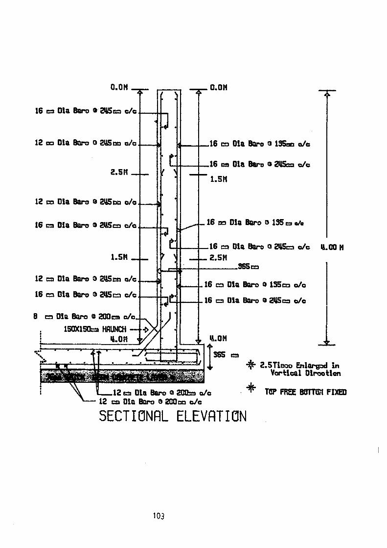
0.O N
16 Din Baru a2M5 +c/c
12 Din & rc o 2M5 qua c/c
2.511
12cac► Din Sra0&5r o%
i6= Din Bama2IS c/c
0.011
16 a Din Bart ® 135c c/c
16ca Din Baram2 c/c
"SF'
16 c,Din Baro®135c,0/e
1.5(4
12 Din Raro02ISxuc/c
16 c Din Barc O2l1Sr c/c
8 a Din Sara a 2001 a c/ c4 15OX15 a HRUNLH -D
LOPi 4/
16=Din Bar*024s=c% LOOM 2.5M
16 a Din Bam0135 ac/c
16caO1aBarua21Sc o%
2.STica Enlarxd in Vwtical Direction
12 a
Din B ro ® 2001 a/c * TO' FRM BOTTU1 FIXED 12 cm Din Barra a 200 c/c
SECTIONAL ELEVATION
103

• • •
• • •
Z12ear0iaMm6 245am+c/c
16 mmDiaBarsa 155mmc%
16 aim Oia Ears a 245 mm c%
12 mmDiaBarsa 24Smma/c
16 m OlaBrea 2gsmma/c
:J: :: : : __
•
0 qi 1 qr r♦
pia Bars o 2 Sms a/c
, I95 mm c%
I - 5.10 M
SECTIONAL PLAN * NOT TO SCALE
104