cadena manual
DESCRIPTION
Cadena ManualTRANSCRIPT

Cadena 2.0: ManualJesse Greenwald
Todd Wallentine

Cadena 2.0: ManualJesse GreenwaldTodd WallentineCopyright © 2007 The SAnToS Laboratory, K-State

iv
Table of Contents1. Overview ....................................................................................................................... 1
Cadena ..................................................................................................................... 1Component Based Development .................................................................................... 1Eclipse Overview ....................................................................................................... 2Cadena Installation ..................................................................................................... 2
2. A Cadena Project ............................................................................................................ 3Overview .................................................................................................................. 3The New Project Wizard ............................................................................................. 3Configuring a Project .................................................................................................. 3
Paths ................................................................................................................ 3Project Dependencies .......................................................................................... 4
3. Style Tier ...................................................................................................................... 5The New Style Wizard ................................................................................................ 5The Style Editor ......................................................................................................... 5Providing the Visual Style ........................................................................................... 5Kinds ....................................................................................................................... 6
Interface Kinds .................................................................................................. 7Component Kinds ............................................................................................... 7Connector Kinds ................................................................................................ 8
Attributes ................................................................................................................ 10Basic Property Types ......................................................................................... 10User Defined Property Types .............................................................................. 11Property Values ................................................................................................ 11
Inheritance ............................................................................................................... 124. Module Tier ................................................................................................................. 13
The New Module Wizard ........................................................................................... 13The Module Editor .................................................................................................... 13Providing the Visual Style .......................................................................................... 13Types ...................................................................................................................... 14
Interface Types ................................................................................................. 15Component Types ............................................................................................. 15
Imported Modules ..................................................................................................... 165. Scenario Tier ................................................................................................................ 17
The New Scenario Wizard .......................................................................................... 17The Scenario Editor .................................................................................................. 17Providing the Visual Style .......................................................................................... 17Imported Modules ..................................................................................................... 18Component Instances ................................................................................................. 18Connections ............................................................................................................. 19Tips on Navigating the Scenario Editor ......................................................................... 19
6. Python Scripting ........................................................................................................... 21Background ............................................................................................................. 21
Environment .................................................................................................... 21Usage ............................................................................................................. 21
Object Model ........................................................................................................... 22Python Enhancements to Object Model ................................................................. 23Modifying the Model ......................................................................................... 26
Putting it all Together ................................................................................................ 26The Premise ..................................................................................................... 27Procedure ........................................................................................................ 27Running .......................................................................................................... 29
Cadena 2.0: Manual
v
7. Plug-In to Cadena ......................................................................................................... 30Overview ................................................................................................................. 30Create a New Platform .............................................................................................. 30
Create the Style ................................................................................................ 30Create the Eclipse Plugin Project ......................................................................... 33Add the Style ................................................................................................... 35Testing the Platform Plugin ................................................................................ 37Add the Visual Style ......................................................................................... 37Prototype the Generator ..................................................................................... 37Add a new Generator Action .............................................................................. 41Continue to Develop ......................................................................................... 41
Glossary .......................................................................................................................... 42Bibliography .................................................................................................................... 45
vi
List of Figures1.1. The Cadena meta-modeling language ............................................................................... 13.1. Property Value Hierarchy ............................................................................................. 127.1. eNesC Interface Kinds ................................................................................................. 317.2. eNesC Connector Kinds ............................................................................................... 327.3. eNesC Connector Kinds in the Cadena Style Editor .......................................................... 327.4. eNesC Component Kinds in the Cadena Style Editor ......................................................... 337.5. Menus to create a new project ...................................................................................... 337.6. New Plugin Project: Name It ........................................................................................ 347.7. New Plugin Project: ID It ............................................................................................ 347.8. New Plugin Project: Complete It ................................................................................... 357.9. The New Style in the New Plugin Project ....................................................................... 367.10. Complete Style Extension point in Eclipse Plugin-in Manifest Editor .................................. 377.11. eNesC Example Module ............................................................................................. 387.12. eNesC Example Scenario ............................................................................................ 387.13. eNesC Example Scenario - Error Messages .................................................................... 397.14. eNesC Example Scenario - Properties ........................................................................... 397.15. eNesC Example Scenario - Python Script Results ............................................................ 41
vii
List of Tables3.1. Visual Style Color Values .............................................................................................. 63.2. Meta-kind properties ..................................................................................................... 63.3. Kind properties ............................................................................................................ 73.4. Port-spec properties ...................................................................................................... 83.5. Port-spec binding properties ........................................................................................... 83.6. Role properties ............................................................................................................. 93.7. Interface type variable properties ..................................................................................... 93.8. Role/Interface type-variable binding properties ................................................................. 103.9. Attribute specification properties ................................................................................... 103.10. Basic Property Types ................................................................................................. 113.11. Typedef properties .................................................................................................... 114.1. Visual Style Color Values ............................................................................................ 144.2. Type properties .......................................................................................................... 144.3. Component Type properties .......................................................................................... 154.4. Component port properties ........................................................................................... 155.1. Visual Style Color Values ............................................................................................ 186.1. Supplementary Attributes in Python Environment ............................................................. 257.1. eNesC Interface Kinds ................................................................................................. 317.2. eNesC Connector Kinds ............................................................................................... 31
1
Chapter 1. OverviewThe Cadena 2.0: Manual was created as a complete reference manual for the Cadena developmentenvironment. It has a feature-centric focus meaning that it describes features and how they are used. Thisis slightly different than the Cadena tutorials which provide a task-centric focus meaning that it describestasks and how they can be accomplished using features available in the Cadena development environment.
CadenaCadena is an Eclipse-based extensible integrated modeling and development framework for component-based systems. Cadena's models are type-centric in that multi-level type systems are used to specify andenforce a variety of architectural constraints relevant to development of large-scale systems and softwareproduct lines.
Cadena provides the following capabilities to system architects, infrastructure developers, and systemdevelopers:
• Define modeling environments for widely-used component models: Cadena's meta-modelingcapabilities can be used to formally capture the definition of widely used component models such asthe CORBA Component Model (CCM), Enterprise Java Beans (EJB), and nesC (a component modelfor sensor networks built on TinyOS). Meta-models can include attributes that represent settings andparameters for underlying middleware frameworks on which systems will be deployed.
• Define domain-specific component models: Cadena meta-modeling can also be applied to specify newcomponent models, including domain-specific component models that are tailored to the characteristicsof a particular domain or underlying middleware capabilities.
• Flexibly combine and extend multiple component models in a single system: Cadena meta-models(called styles) can be directly manipulated using style operations. This provides a variety of powerfuland useful capabilities to system architects.
• Styles can be extended through inheritance. This enables reuse of meta-model definitions, andfacilities refinement of platform definitions (multi-step platform-independent to platform-specificmodel refinement).
• Multiple styles can be combined within the same architecture model environment to supportdevelopment of systems of systems that incorporate multiple component models.
• Define end-to-end model-driven development environments: Cadena's base set of capabilities canbe extended using plug-in mechanisms based on the Eclipse plug-in architecture. This enablesinfrastructure developers to build end-to-end model-driven development environments that includefacilities for editing component implementations, model-level configuration of middleware capabilities,code generation, simulation, verification, and creating system builds. Plug-ins can also be developedto link other development tools including tools for requirements capture and down-stream class-levelmodeling tools such as Rational Rose or Modeler or iLogix Rhapsody.
Figure 1.1. The Cadena meta-modeling language
Component Based DevelopmentTODO: Give an overview of component based development here. Talk about how components provideinterfaces which are connected by connectors.

Overview
2
Eclipse OverviewTODO: A short description of Eclipse here
Cadena InstallationThis manual assumes that you have Cadena installed properly. For more information on installing Cadenaplease read the Cadena 2.0: Install Guide.
3
Chapter 2. A Cadena ProjectOverview
A project serves as the basic organizational unit of Cadena. Related artifacts can be stored and groupedwithin projects. Artifacts of one project may be made visible to another project by creating a projectdependency between the two projects.
The New Project WizardBefore any Cadena artifacts can be created, a project must be created to contain them. To create a newproject:
• Select "File # New # Project..." from the main menu.
• The new project dialog should appear. From the tree on the left, select "Cadena # Cadena Project" andthen click the "Next" button.
• The Cadena Project page of the wizard should appear. To continue, a valid project name must be entered.Once a valid project name has been entered, the "Finish" button may be clicked to create the project.
The new project should now show up within the resource navigator view.
Configuring a Project
PathsWithin a project, paths are used to specify what directories artifacts must be placed in to be visible to otherartifacts. Separate directory lists are maintained for each type of Cadena artifact. When a new project iscreated, a default set of specification paths are configured: specification/style, specification/module, andspecification/scenario for styles, modules and scenarios respectively.
To view the specification paths for a project:
• Right-click on the project within the resource navigator view and select "Properties" from the mainmenu.
• The project properties dialog should appear. From the tree on the left, select "Cadena SpecificationPaths". The specification paths page should appear to the right.
There is a separate tab for each type of Cadena artifact. The specification path of each type of artifact canbe set through these tabs. The list within each tab shows the currently defined paths.
A path can be removed by selecting it from the list and clicking the "Remove" button. Clicking the "AddFolder..." button will cause a folder selection dialog to be displayed which allows additional paths to beadded to the list.
If a path specified in Cadena configuration cannot be resolved it will still be listed. When this happens itwill be denoted in that dialog with a RED X. You can remove this path from the list by selecting it andpressing the "Remove" button. You can also remove all bad (or errorneous) paths from the list using theCleanup button.
A Cadena Project
4
Project DependenciesBy default, artifacts within one project are not visible to artifacts within other projects. However, theseartifacts can be made visible by creating a project reference. Once a reference to a project is established,artifacts that are contained within the referenced project will be visible within the project that created the
reference. 1.
To view a project's references:
• Right-click on the project within the resource navigator view and select "Properties" from the mainmenu.
• The project properties dialog should appear. From the tree on the left, select "Project References". Thereferences page should appear to the right.
References to projects are indicated by the checkboxes located next to the name of each project. A referencecan be added or removed by clicking on the checkbox of a project.
1 For the artifacts of one project to be visible to the artifacts of a referencing project, the artifacts must be located on the referenced project'sspecification paths.
5
Chapter 3. Style TierInside a Cadena style, the shapes (or structures) of the architectural elements are described (i.e., thevocabulary of a platform is introduced). Another way to look at this is that the style-tier is the factory forthe constituent parts of an architecture.
The New Style WizardTo create a new style:
• Use the navigator view to browse to a folder within a Cadena project where the style will be placed.The folder that is chosen should be a part of the style path for the project.
• Right click on the chosen folder and select " New # Other " from the pop-up menu.
• The new resource dialog should appear. From the tree on the left, select " Cadena # Cadena Style " andthen click the "Next" button.
• The Cadena Style wizard page of the wizard should appear. To continue, a valid style name must beentered. Once a valid style name has been selected, click the "Finish" button to create the style.
If the style is succesfully created, a style editor for the new style will be opened.
The Style EditorThe style editor is used to view and modify Cadena styles. The editor has two tabs: the Overview tab, andthe Table tab. The Overview tab is used to view and modify general aspects of the style while the Table tabprovides a table based view for viewing and modifying the individual elements that comprise the model.
Providing the Visual StyleThe Cadena Style editor allows the user to configure visual properties of the editor so that the user canhave a richer experience. The customizations are rudimentary at this time but should be sufficient for mostusers. If more customizations are necessary, a plugin should be created for the style.
To make changes to the visual style a user must create a file with a name that follows this pattern:<styleFileName>.visuals (where <styleFileName> is the name of the style file before the .style). This willbe a simple text file that uses the Java properties format. Each property provides the Style editor withconfigurations that can enhance the look-n-feel of the editor to match user expectations. Therefore, theproperty names and values are important.
The first configurable item is the icon used for interface kinds. The naming scheme that is used isbased upon the name of the kind followed by .icon. For example, if we have an interface kind namedtestInterfaceKind, we can set the icon that is used to denote it by setting testInterfaceKind.icon=test.gif.We suggest you use an icon that whose size is 16x16 (pixels).
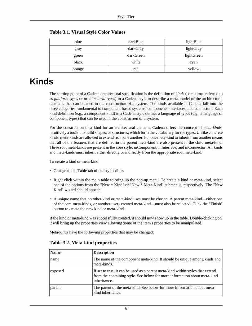
The second configurable item is the color used for component kinds (as well as meta-kinds).The naming scheme that is used is based upon the name of the kind followed by .color. Forexample, if we have a component kind named testComponent, we can set the color that is used totestComponent.color=red. The values that can be used must be in the set of Eclipse Draw2d color constants(org.eclipse.draw2d.ColorConstants) or a proper HEX value (e.g., #FF0000 is red and #CCEEFF is bluish).This set of colors is listed in Table 3.1, “Visual Style Color Values”.
Style Tier
6
Table 3.1. Visual Style Color Values
blue darkBlue lightBlue
gray darkGray lightGray
green darkGreen lightGreen
black white cyan
orange red yellow
KindsThe starting point of a Cadena architectural specification is the definition of kinds (sometimes referred toas platform types or architectural types) in a Cadena style to describe a meta-model of the architecturalelements that can be used in the construction of a system. The kinds available in Cadena fall into thethree categories fundamental to component-based systems: components, interfaces, and connectors. Eachkind definition (e.g., a component kind) in a Cadena style defines a language of types (e.g., a language ofcomponent types) that can be used in the construction of a system.
For the construction of a kind for an architectural element, Cadena offers the concept of meta-kinds,intuitively a toolkit to build shapes, or structures, which form the vocabulary for the types. Unlike concretekinds, meta-kinds are allowed to extend from one another. For one meta-kind to inherit from another meansthat all of the features that are defined in the parent meta-kind are also present in the child meta-kind.Three root meta-kinds are present in the core style: mComponent, mInterface, and mConnector. All kindsand meta-kinds must inherit either directly or indirectly from the appropriate root meta-kind.
To create a kind or meta-kind:
• Change to the Table tab of the style editor.
• Right click within the main table to bring up the pop-up menu. To create a kind or meta-kind, selectone of the options from the "New * Kind" or "New * Meta-Kind" submenus, respectively. The "NewKind" wizard should appear.
• A unique name that no other kind or meta-kind uses must be chosen. A parent meta-kind—either oneof the core meta-kinds, or another user- created meta-kind—must also be selected. Click the "Finish"button to create the new kind or meta-kind.
If the kind or meta-kind was successfully created, it should now show up in the table. Double-clicking onit will bring up the properties view allowing some of the item's properties to be manipulated.
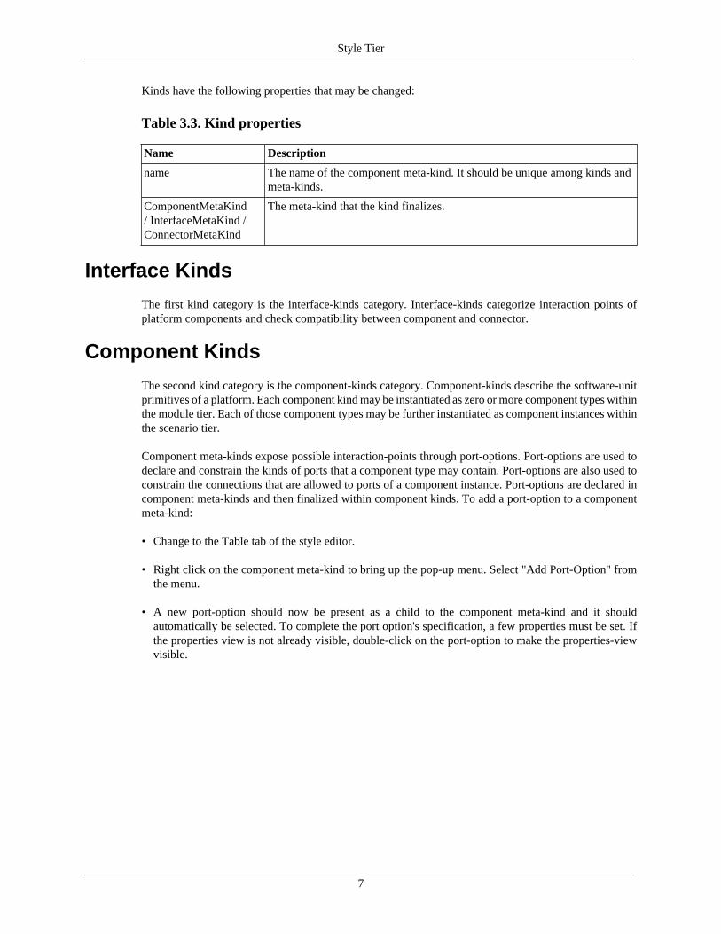
Meta-kinds have the following properties that may be changed:
Table 3.2. Meta-kind properties
Name Description
name The name of the component meta-kind. It should be unique among kinds andmeta-kinds.
exposed If set to true, it can be used as a parent meta-kind within styles that extendfrom the containing style. See below for more information about meta-kindinheritance.
parent The parent of the meta-kind. See below for more information about meta-kind inheritance.
Style Tier
7
Kinds have the following properties that may be changed:
Table 3.3. Kind properties
Name Description
name The name of the component meta-kind. It should be unique among kinds andmeta-kinds.
ComponentMetaKind/ InterfaceMetaKind /ConnectorMetaKind
The meta-kind that the kind finalizes.
Interface Kinds
The first kind category is the interface-kinds category. Interface-kinds categorize interaction points ofplatform components and check compatibility between component and connector.
Component Kinds
The second kind category is the component-kinds category. Component-kinds describe the software-unitprimitives of a platform. Each component kind may be instantiated as zero or more component types withinthe module tier. Each of those component types may be further instantiated as component instances withinthe scenario tier.
Component meta-kinds expose possible interaction-points through port-options. Port-options are used todeclare and constrain the kinds of ports that a component type may contain. Port-options are also used toconstrain the connections that are allowed to ports of a component instance. Port-options are declared incomponent meta-kinds and then finalized within component kinds. To add a port-option to a componentmeta-kind:
• Change to the Table tab of the style editor.
• Right click on the component meta-kind to bring up the pop-up menu. Select "Add Port-Option" fromthe menu.
• A new port-option should now be present as a child to the component meta-kind and it shouldautomatically be selected. To complete the port option's specification, a few properties must be set. Ifthe properties view is not already visible, double-click on the port-option to make the properties-viewvisible.
Style Tier
8
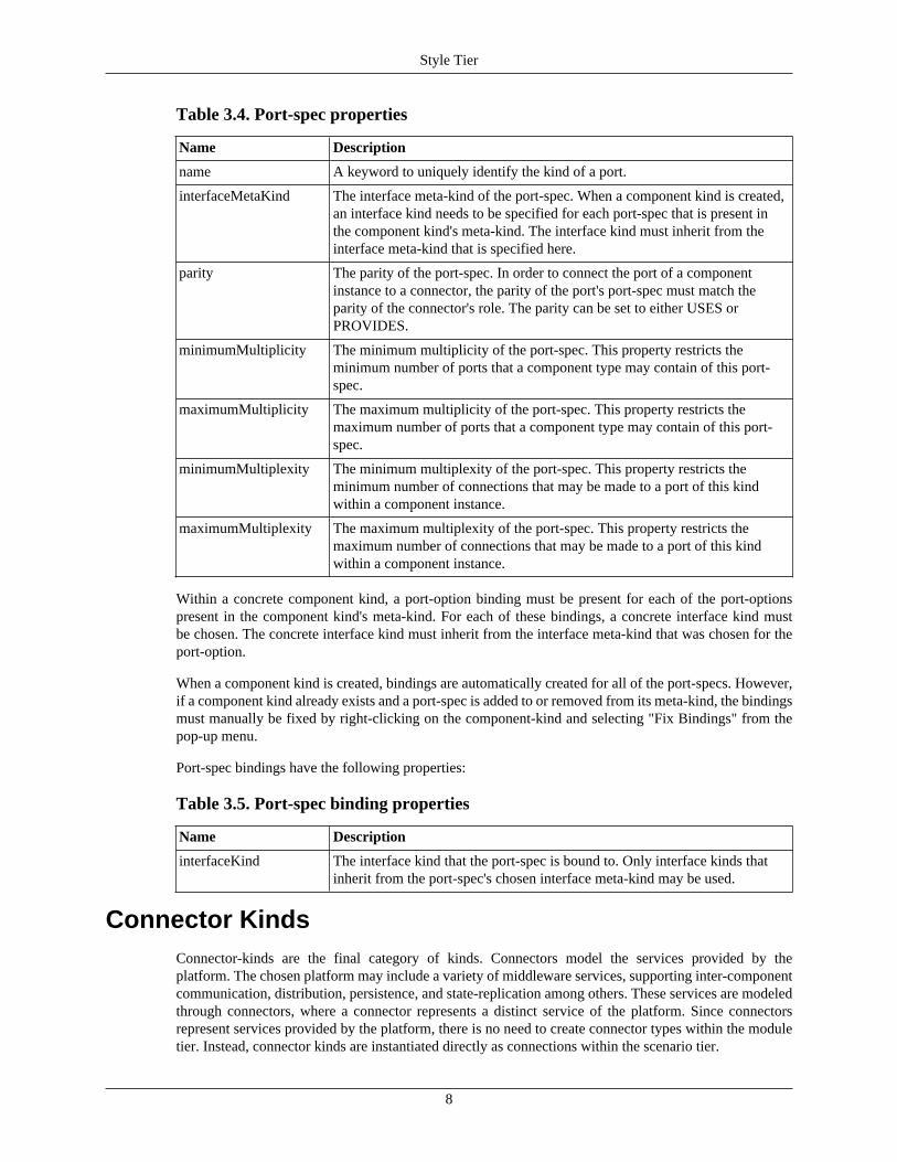
Table 3.4. Port-spec properties
Name Description
name A keyword to uniquely identify the kind of a port.
interfaceMetaKind The interface meta-kind of the port-spec. When a component kind is created,an interface kind needs to be specified for each port-spec that is present inthe component kind's meta-kind. The interface kind must inherit from theinterface meta-kind that is specified here.
parity The parity of the port-spec. In order to connect the port of a componentinstance to a connector, the parity of the port's port-spec must match theparity of the connector's role. The parity can be set to either USES orPROVIDES.
minimumMultiplicity The minimum multiplicity of the port-spec. This property restricts theminimum number of ports that a component type may contain of this port-spec.
maximumMultiplicity The maximum multiplicity of the port-spec. This property restricts themaximum number of ports that a component type may contain of this port-spec.
minimumMultiplexity The minimum multiplexity of the port-spec. This property restricts theminimum number of connections that may be made to a port of this kindwithin a component instance.
maximumMultiplexity The maximum multiplexity of the port-spec. This property restricts themaximum number of connections that may be made to a port of this kindwithin a component instance.
Within a concrete component kind, a port-option binding must be present for each of the port-optionspresent in the component kind's meta-kind. For each of these bindings, a concrete interface kind mustbe chosen. The concrete interface kind must inherit from the interface meta-kind that was chosen for theport-option.
When a component kind is created, bindings are automatically created for all of the port-specs. However,if a component kind already exists and a port-spec is added to or removed from its meta-kind, the bindingsmust manually be fixed by right-clicking on the component-kind and selecting "Fix Bindings" from thepop-up menu.
Port-spec bindings have the following properties:
Table 3.5. Port-spec binding properties
Name Description
interfaceKind The interface kind that the port-spec is bound to. Only interface kinds thatinherit from the port-spec's chosen interface meta-kind may be used.
Connector KindsConnector-kinds are the final category of kinds. Connectors model the services provided by theplatform. The chosen platform may include a variety of middleware services, supporting inter-componentcommunication, distribution, persistence, and state-replication among others. These services are modeledthrough connectors, where a connector represents a distinct service of the platform. Since connectorsrepresent services provided by the platform, there is no need to create connector types within the moduletier. Instead, connector kinds are instantiated directly as connections within the scenario tier.
Style Tier
9
Each connector definition consists of a number of role declarations, much like the port-optionsin component-kinds. Single-role connectors abstract services such as timeout-generators; multi-roleconnectors model inter-component communication-services. When a connector kind is instantiated asa connection within the scenario tier, each of the connection's roles must be connected to a port of acomponent instance.
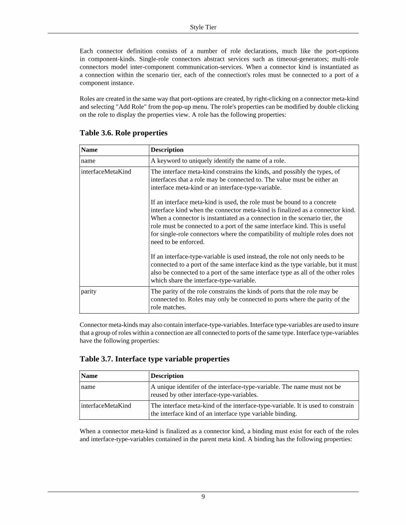
Roles are created in the same way that port-options are created, by right-clicking on a connector meta-kindand selecting "Add Role" from the pop-up menu. The role's properties can be modified by double clickingon the role to display the properties view. A role has the following properties:
Table 3.6. Role properties
Name Description
name A keyword to uniquely identify the name of a role.
interfaceMetaKind The interface meta-kind constrains the kinds, and possibly the types, ofinterfaces that a role may be connected to. The value must be either aninterface meta-kind or an interface-type-variable.
If an interface meta-kind is used, the role must be bound to a concreteinterface kind when the connector meta-kind is finalized as a connector kind.When a connector is instantiated as a connection in the scenario tier, therole must be connected to a port of the same interface kind. This is usefulfor single-role connectors where the compatibility of multiple roles does notneed to be enforced.
If an interface-type-variable is used instead, the role not only needs to beconnected to a port of the same interface kind as the type variable, but it mustalso be connected to a port of the same interface type as all of the other roleswhich share the interface-type-variable.
parity The parity of the role constrains the kinds of ports that the role may beconnected to. Roles may only be connected to ports where the parity of therole matches.
Connector meta-kinds may also contain interface-type-variables. Interface type-variables are used to insurethat a group of roles within a connection are all connected to ports of the same type. Interface type-variableshave the following properties:
Table 3.7. Interface type variable properties
Name Description
name A unique identifer of the interface-type-variable. The name must not bereused by other interface-type-variables.
interfaceMetaKind The interface meta-kind of the interface-type-variable. It is used to constrainthe interface kind of an interface type variable binding.
When a connector meta-kind is finalized as a connector kind, a binding must exist for each of the rolesand interface-type-variables contained in the parent meta kind. A binding has the following properties:
Style Tier
10
Table 3.8. Role/Interface type-variable binding properties
Name Description
interfaceKind The interface kind that this binding is bound to. (Note: this property is notpresent if the binding is for a role and the role specified is an interface-type-variable as it's interface constraint). Only interface kinds that inherit from therole's chosen interface meta-kind may be used.
AttributesWhile kinds and kind features are useful for creating the functional aspects of a model, it is often usefulto attach non-functional data in the form of non-stateful attributes. Attributes are useful in configuringthe underlying middleware and service infrastructure of a system. The attribute values can then beused for many things including schedulability analysis, code generation, configuration management, anddeployment configuration generation.
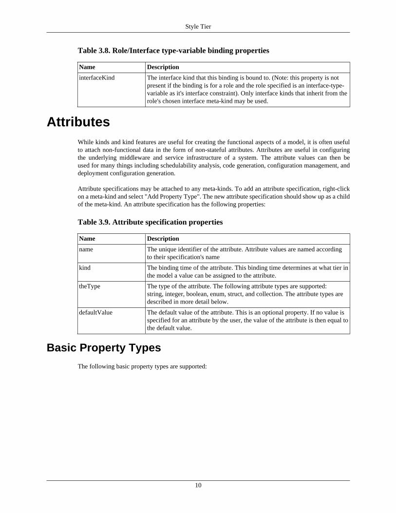
Attribute specifications may be attached to any meta-kinds. To add an attribute specification, right-clickon a meta-kind and select "Add Property Type". The new attribute specification should show up as a childof the meta-kind. An attribute specification has the following properties:
Table 3.9. Attribute specification properties
Name Description
name The unique identifier of the attribute. Attribute values are named accordingto their specification's name
kind The binding time of the attribute. This binding time determines at what tier inthe model a value can be assigned to the attribute.
theType The type of the attribute. The following attribute types are supported:string, integer, boolean, enum, struct, and collection. The attribute types aredescribed in more detail below.
defaultValue The default value of the attribute. This is an optional property. If no value isspecified for an attribute by the user, the value of the attribute is then equal tothe default value.
Basic Property Types
The following basic property types are supported:
Style Tier
11
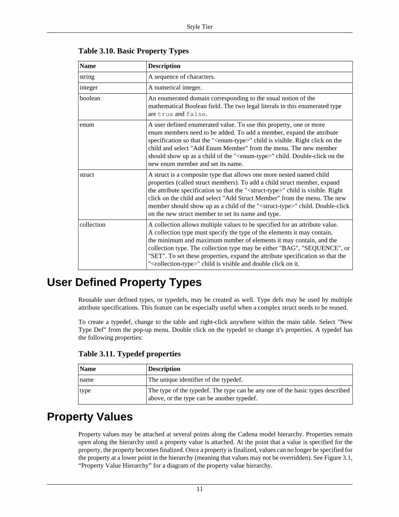
Table 3.10. Basic Property Types
Name Description
string A sequence of characters.
integer A numerical integer.
boolean An enumerated domain corresponding to the usual notion of themathematical Boolean field. The two legal literals in this enumerated typeare true and false.
enum A user defined enumerated value. To use this property, one or moreenum members need to be added. To add a member, expand the attributespecification so that the "<enum-type>" child is visible. Right click on thechild and select "Add Enum Member" from the menu. The new membershould show up as a child of the "<enum-type>" child. Double-click on thenew enum member and set its name.
struct A struct is a composite type that allows one more nested named childproperties (called struct members). To add a child struct member, expandthe attribute specification so that the "<struct-type>" child is visible. Rightclick on the child and select "Add Struct Member" from the menu. The newmember should show up as a child of the "<struct-type>" child. Double-clickon the new struct member to set its name and type.
collection A collection allows multiple values to be specified for an attribute value.A collection type must specify the type of the elements it may contain,the minimum and maximum number of elements it may contain, and thecollection type. The collection type may be either "BAG", "SEQUENCE", or"SET". To set these properties, expand the attribute specification so that the"<collection-type>" child is visible and double click on it.
User Defined Property TypesReusable user defined types, or typedefs, may be created as well. Type defs may be used by multipleattribute specifications. This feature can be especially useful when a complex struct needs to be reused.
To create a typedef, change to the table and right-click anywhere within the main table. Select "NewType Def" from the pop-up menu. Double click on the typedef to change it's properties. A typedef hasthe following properties:
Table 3.11. Typedef properties
Name Description
name The unique identifier of the typedef.
type The type of the typedef. The type can be any one of the basic types describedabove, or the type can be another typedef.
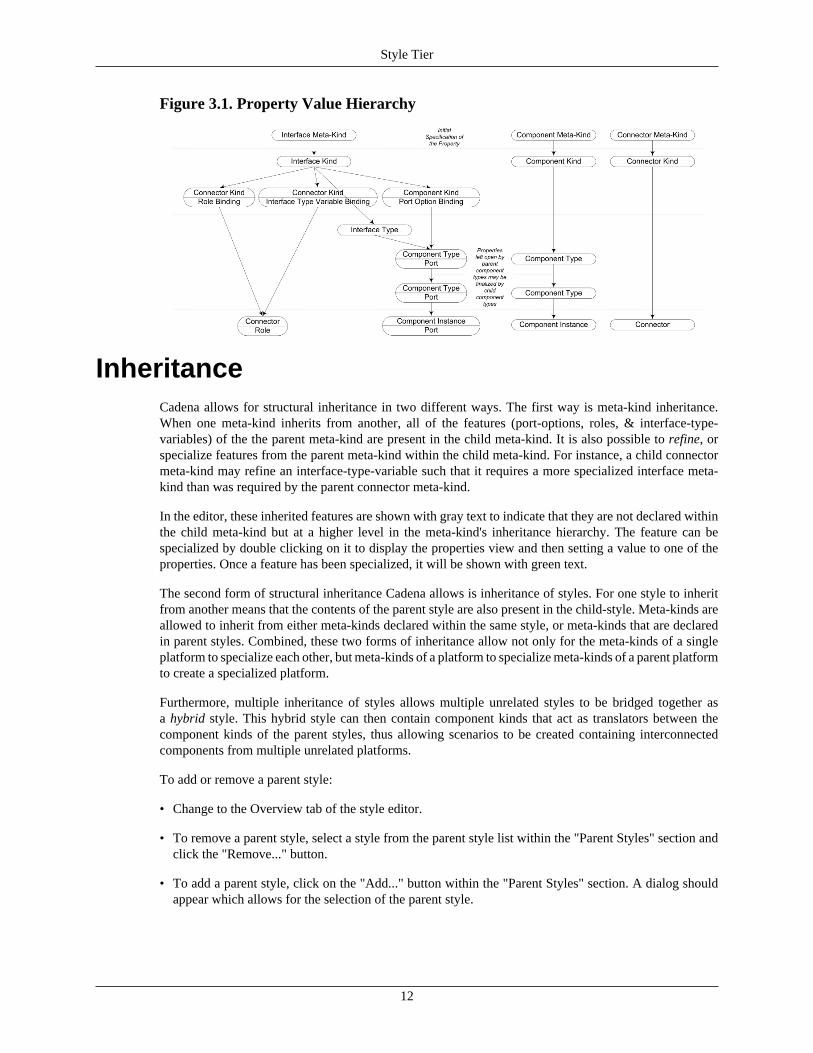
Property ValuesProperty values may be attached at several points along the Cadena model hierarchy. Properties remainopen along the hierarchy until a property value is attached. At the point that a value is specified for theproperty, the property becomes finalized. Once a property is finalized, values can no longer be specified forthe property at a lower point in the hierarchy (meaning that values may not be overridden). See Figure 3.1,“Property Value Hierarchy” for a diagram of the property value hierarchy.
Style Tier
12
Figure 3.1. Property Value Hierarchy
InheritanceCadena allows for structural inheritance in two different ways. The first way is meta-kind inheritance.When one meta-kind inherits from another, all of the features (port-options, roles, & interface-type-variables) of the the parent meta-kind are present in the child meta-kind. It is also possible to refine, orspecialize features from the parent meta-kind within the child meta-kind. For instance, a child connectormeta-kind may refine an interface-type-variable such that it requires a more specialized interface meta-kind than was required by the parent connector meta-kind.
In the editor, these inherited features are shown with gray text to indicate that they are not declared withinthe child meta-kind but at a higher level in the meta-kind's inheritance hierarchy. The feature can bespecialized by double clicking on it to display the properties view and then setting a value to one of theproperties. Once a feature has been specialized, it will be shown with green text.
The second form of structural inheritance Cadena allows is inheritance of styles. For one style to inheritfrom another means that the contents of the parent style are also present in the child-style. Meta-kinds areallowed to inherit from either meta-kinds declared within the same style, or meta-kinds that are declaredin parent styles. Combined, these two forms of inheritance allow not only for the meta-kinds of a singleplatform to specialize each other, but meta-kinds of a platform to specialize meta-kinds of a parent platformto create a specialized platform.
Furthermore, multiple inheritance of styles allows multiple unrelated styles to be bridged together asa hybrid style. This hybrid style can then contain component kinds that act as translators between thecomponent kinds of the parent styles, thus allowing scenarios to be created containing interconnectedcomponents from multiple unrelated platforms.
To add or remove a parent style:
• Change to the Overview tab of the style editor.
• To remove a parent style, select a style from the parent style list within the "Parent Styles" section andclick the "Remove..." button.
• To add a parent style, click on the "Add..." button within the "Parent Styles" section. A dialog shouldappear which allows for the selection of the parent style.

13
Chapter 4. Module TierOnce an architecture or platform has been described in a style (see Chapter 3, Style Tier ), a moduleusing that style can be created. Inside a module users can create component types and interface typescorresponding to the component kinds and interface kinds described within the style.
The New Module WizardTo create a new module:
• Use the navigator view to browse to a folder within a Cadena project where the module will be placed.The folder that is chosen should be a part of the module path for the project. The standard location forthis is in the specification/module folder.
• Right click on the chosen folder and select " New # Other " from the pop-up menu.
• The new resource dialog should appear. From the tree on the left, select " Cadena # Cadena Module "and then click the "Next" button.
• The Cadena Module wizard page should appear. To continue, a valid module name must be entered.The desired style of the module must also be selected. Once a valid module name and style have beenselected, the "Finish" button must be clicked to create the module.
If the module is succesfully created, a module editor for the new module will be opened.
The Module EditorThe module editor is used to view and modify Cadena modules. The editor has two tabs: the Overview tab,and the Table tab. The Overview tab is used to view and modify general aspects of the module while theTable tab provides a table based view for viewing and modifying the individual elements that comprisethe model.
Providing the Visual StyleThe Cadena Module editor allows the user to configure visual properties of the editor so that the user canhave a richer experience. The customizations are rudimentary at this time but should be sufficient for mostusers. If more customizations are necessary, a plugin should be created for the style.
To make changes to the visual style a user must create a file with a name that follows this pattern:<moduleFileName>.visuals (where <moduleFileName> is the name of the style file before the .module).This will be a simple text file that uses the Java properties format. Each property provides the Module editorwith configurations that can enhance the look-n-feel of the editor to match user expectations. Therefore,the property names and values are important.
The first configurable item is the icon used for interface types. The naming scheme that is used isbased upon the name of the type followed by .icon. For example, if we have an interface type namedtestInterfaceType, we can set the icon that is used to denote it by setting testInterfaceType.icon=test.gif.We suggest you use an icon that whose size is 16x16 (pixels).
The second configurable item is the color used for component types. The naming scheme that is used isbased upon the name of the type followed by .color. For example, if we have a component kind namedtestComponentType, we can set the color that is used to testComponentType.color=red. The values that
Module Tier
14
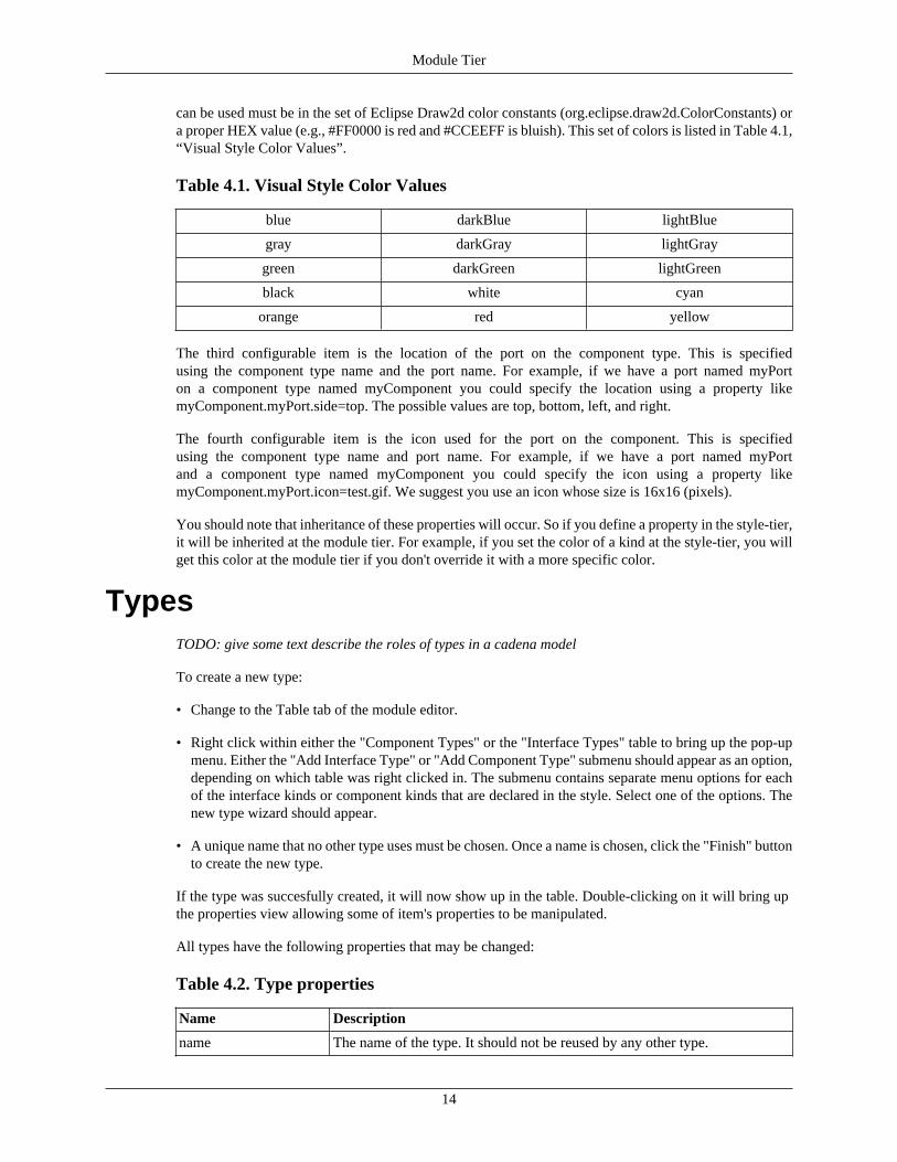
can be used must be in the set of Eclipse Draw2d color constants (org.eclipse.draw2d.ColorConstants) ora proper HEX value (e.g., #FF0000 is red and #CCEEFF is bluish). This set of colors is listed in Table 4.1,“Visual Style Color Values”.
Table 4.1. Visual Style Color Values
blue darkBlue lightBlue
gray darkGray lightGray
green darkGreen lightGreen
black white cyan
orange red yellow
The third configurable item is the location of the port on the component type. This is specifiedusing the component type name and the port name. For example, if we have a port named myPorton a component type named myComponent you could specify the location using a property likemyComponent.myPort.side=top. The possible values are top, bottom, left, and right.
The fourth configurable item is the icon used for the port on the component. This is specifiedusing the component type name and port name. For example, if we have a port named myPortand a component type named myComponent you could specify the icon using a property likemyComponent.myPort.icon=test.gif. We suggest you use an icon whose size is 16x16 (pixels).
You should note that inheritance of these properties will occur. So if you define a property in the style-tier,it will be inherited at the module tier. For example, if you set the color of a kind at the style-tier, you willget this color at the module tier if you don't override it with a more specific color.
TypesTODO: give some text describe the roles of types in a cadena model
To create a new type:
• Change to the Table tab of the module editor.
• Right click within either the "Component Types" or the "Interface Types" table to bring up the pop-upmenu. Either the "Add Interface Type" or "Add Component Type" submenu should appear as an option,depending on which table was right clicked in. The submenu contains separate menu options for eachof the interface kinds or component kinds that are declared in the style. Select one of the options. Thenew type wizard should appear.
• A unique name that no other type uses must be chosen. Once a name is chosen, click the "Finish" buttonto create the new type.
If the type was succesfully created, it will now show up in the table. Double-clicking on it will bring upthe properties view allowing some of item's properties to be manipulated.
All types have the following properties that may be changed:
Table 4.2. Type properties
Name Description
name The name of the type. It should not be reused by any other type.
Module Tier
15
Interface TypesEach port of a component designates one interface type as the shape to which it conforms. A connector kindmay use the interface types of ports to insure that only ports of compatible interface types are connectedtogether by a connector.
If an interface type is selected, all of the ports of that interface type will be selected in the componenttypes table.
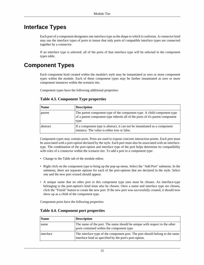
Component TypesEach component kind created within the module's style may be instantiated as zero or more componenttypes within the module. Each of these component types may be further instantiated as zero or morecomponent instances within the scenario tier.
Component types have the following additional properties:
Table 4.3. Component Type properties
Name Description
parent The parent component type of the component type. A child component typeof a parent component type inherits all of the ports of it's parent componenttype.
abstract If a component type is abstract, it can not be instantiated as a componentinstance. The value is either true or false.
Component types may contain ports. Ports are used to expose concrete interaction-points. Each port mustbe associated with a port-option declared by the style. Each port must also be associated with an interface-type. The combination of the port-option and interface type of the port helps determine its compatibilitywith roles of a connector within the scenario tier. To add a port to a component type:
• Change to the Table tab of the module editor.
• Right click on the component type to bring up the pop-up menu. Select the "Add Port" submenu. In thesubmenu, there are separate options for each of the port-options that are declared in the style. Selectone and the new port wizard should appear.
• A unique name that no other port in this component type uses must be chosen. An interface-typebelonging to the port-option's kind must also be chosen. Once a name and interface type are chosen,click the "Finish" button to create the new port. If the new port was successfully created, it should nowshow up as a child of the component type.
Component ports have the following properties:
Table 4.4. Component port properties
Name Description
name The name of the port. The name should be unique with respect to the otherports contained within the component type.
interface The interface type of the component port. The port should belong to the sameinterface kind as specified by the port's port-option.
Module Tier
16
Imported ModulesIn order for a child component type to extend another parent component type, the parent component typemust be visible. In order for a component port to use an interface type as its type, the interface type mustalso be visible. Types declared within a module are automatically visible to all of the other types withinthe same module. To make a type declared in one module visible to types declared in another module, themodule where the type is declared must be imported by the other module. To view and modify a module'simport list:
• Change to the Overview tab of the module editor. The "Imported Modules" section of the overviewpage shows the list of currently imported modules (by default, this list is empty).
• To add a module to the import list, click the "Add..." button to the right of the list. A dialog will appearallowing modules to be selected for import. Select the modules for import and click the "OK" button.The import list should now be updated to show the newly imported modules.
• To remove a module from the import list, select the module from the list and click the "Remove..."button. The import list should now be updated.
17
Chapter 5. Scenario TierOnce an architecture or platform has been described in a style (see Chapter 3, Style Tier) and a modulewith component types has been created (see Chapter 4, Module Tier), a scenario can be created. Scenarioscontain instances of component types, instances of other scenarios (as nested scenarios), and connectorswhich tie the instances together.
The New Scenario WizardTo create a new scenario:
• Use the navigator view to browse to a folder within a Cadena project where the scenario will be placed.The folder that is chosen should be a part of the scenario path for the project. The standard location forthis is in the specification/scenario folder.
• Right click on the chosen folder and select " New # Other " from the pop-up menu.
• The new resource dialog should appear. From the tree on the left, select " Cadena # Cadena Scenario" and then click the "Next" button.
• The Cadena Scenario wizard page of the wizard should appear. To continue, a valid scenario name mustbe entered. The desired style of the scenario must also be selected. Once a valid scenario name and stylehave been selected, the "Finish" button may be clicked to create the scenario.
If the scenario is succesfully created, a scenario editor for the new scenario will be opened.
The Scenario EditorThe scenario editor is used to view and modify Cadena scenarios. The editor has three tabs: the Overviewtab, the Table tab, and the Graph tab. The Overview tab is used to view and modify general aspects of thescenario. The Table tab provides a table based view for viewing and modifying the individual elements thatcomprise the model. The Graph tab provides a graph based view for viewing and modifying the individualelements of the model as well.
Providing the Visual StyleThe Cadena Scenario editor allows the user to configure visual properties of the editor so that the user canhave a richer experience. The customizations are rudimentary at this time but should be sufficient for mostusers. If more customizations are necessary, a plugin should be created for the style.
To make changes to the visual style a user must create a file with a name that follows this pattern:<scenarioFileName>.visuals (where <scenarioFileName> is the name of the style file before the .scenario).This will be a simple text file that uses the Java properties format. Each property provides the Scenarioeditor with configurations that can enhance the look-n-feel of the editor to match user expectations.Therefore, the property names and values are important.
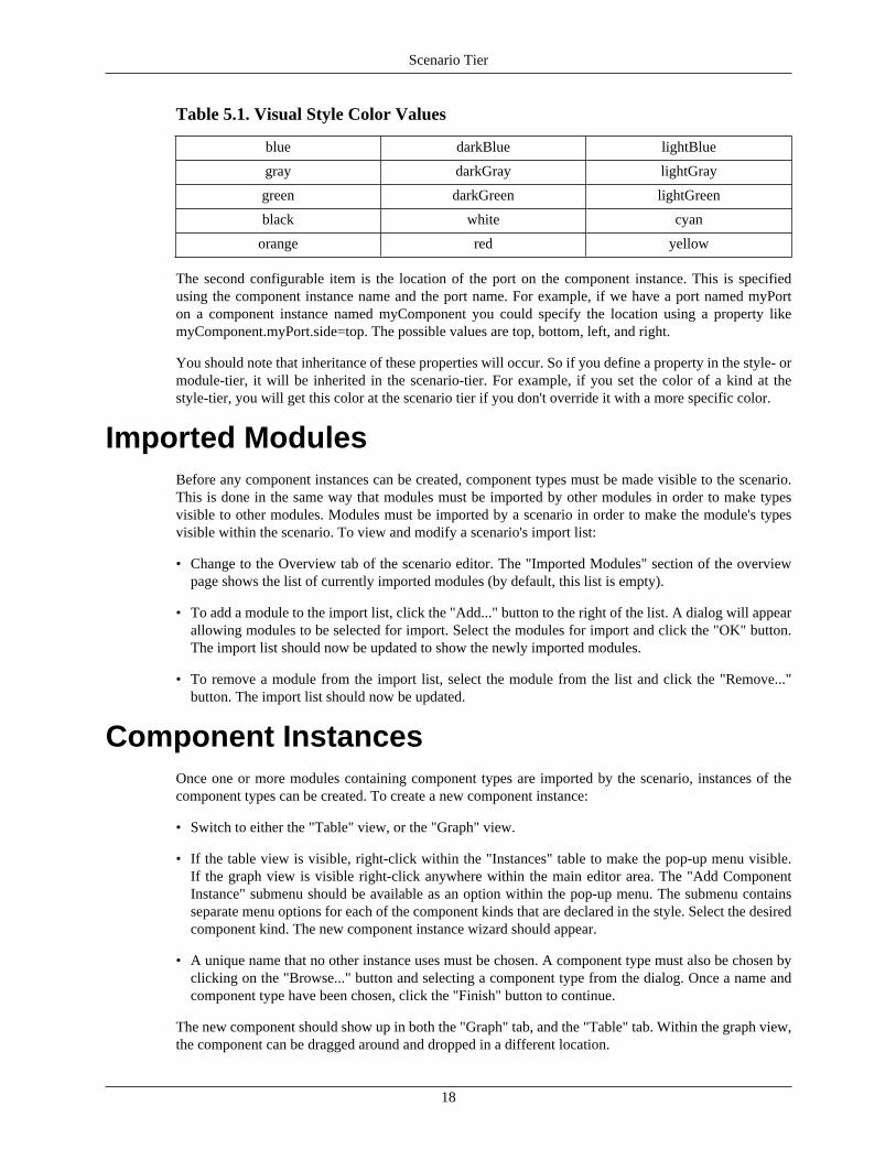
The first configurable item is the color used for component instances. The naming scheme that is used isbased upon the name of the instance followed by .color. For example, if we have a component instancenamed testComponent, we can set the color that is used to testComponent.color=red. The values that canbe used must be in the set of Eclipse Draw2d color constants (org.eclipse.draw2d.ColorConstants) or aproper HEX value (e.g., #FF0000 is red and #CCEEFF is bluish). This set of colors is listed in Table 5.1,“Visual Style Color Values”.
Scenario Tier
18
Table 5.1. Visual Style Color Values
blue darkBlue lightBlue
gray darkGray lightGray
green darkGreen lightGreen
black white cyan
orange red yellow
The second configurable item is the location of the port on the component instance. This is specifiedusing the component instance name and the port name. For example, if we have a port named myPorton a component instance named myComponent you could specify the location using a property likemyComponent.myPort.side=top. The possible values are top, bottom, left, and right.
You should note that inheritance of these properties will occur. So if you define a property in the style- ormodule-tier, it will be inherited in the scenario-tier. For example, if you set the color of a kind at thestyle-tier, you will get this color at the scenario tier if you don't override it with a more specific color.
Imported ModulesBefore any component instances can be created, component types must be made visible to the scenario.This is done in the same way that modules must be imported by other modules in order to make typesvisible to other modules. Modules must be imported by a scenario in order to make the module's typesvisible within the scenario. To view and modify a scenario's import list:
• Change to the Overview tab of the scenario editor. The "Imported Modules" section of the overviewpage shows the list of currently imported modules (by default, this list is empty).
• To add a module to the import list, click the "Add..." button to the right of the list. A dialog will appearallowing modules to be selected for import. Select the modules for import and click the "OK" button.The import list should now be updated to show the newly imported modules.
• To remove a module from the import list, select the module from the list and click the "Remove..."button. The import list should now be updated.
Component InstancesOnce one or more modules containing component types are imported by the scenario, instances of thecomponent types can be created. To create a new component instance:
• Switch to either the "Table" view, or the "Graph" view.
• If the table view is visible, right-click within the "Instances" table to make the pop-up menu visible.If the graph view is visible right-click anywhere within the main editor area. The "Add ComponentInstance" submenu should be available as an option within the pop-up menu. The submenu containsseparate menu options for each of the component kinds that are declared in the style. Select the desiredcomponent kind. The new component instance wizard should appear.
• A unique name that no other instance uses must be chosen. A component type must also be chosen byclicking on the "Browse..." button and selecting a component type from the dialog. Once a name andcomponent type have been chosen, click the "Finish" button to continue.
The new component should show up in both the "Graph" tab, and the "Table" tab. Within the graph view,the component can be dragged around and dropped in a different location.
Scenario Tier
19
ConnectionsOnce one or more instances have been created, connections may be created to connect the instancestogether. Connections may be made a few different ways. The first way to make a connection is describedbelow:
• Switch to either the "Table" view, or the "Graph" view.
• If the table view is visible, right-click within the "Instances" or "Connections" tables to make the pop-upmenu visible. If the graph view is visible right-click anywhere within the main editor area. The "AddConnector" submenu should be available as an option within the pop-up menu. The submenu containsseparate menu options for each of the connector kinds that are declared in the style. Select one of theoptions. The new connection wizard should appear.
• The main table in the wizard displays each role of the selected connector kind. Each role must be boundto a type-correct port. To bind a role, select the binding from the table and choose an instance and portcombination from the binding drop down box. Once a type-correct binding has been chosen for eachrole, click the "Finish" button to create the connection.
The new connection should show up in both the "Graph" tab, and the "Table" tab. Within the graph view,the connection can be dragged around and dropped in a different location.
To limit the available options displayed in the binding drop down box, multiple instances or ports maybe selected before opening the wizard. For instance if two separate instances are selected, only ports fromthose two instances will be available as options in the bindings drop down. If an instance and a port fromanother instance are selected, only ports from the selected instance, and the selected port will be displayedin the drop down box.
Connections can also be created in the following way:
• Switch to the "Table" view.
• Right click on an instance's port within the "Instances" table to display the pop-up menu. The "NewConnection for Port" submenu should be available as an option within the pop-up menu. The submenucontains separate menu options for each of the connector kind/role combinations that the port may bebound to. Select the desired connector kind/role combination. The new connection wizard should bedisplayed. The selected role should already be bound to the port that was right clicked on. The remainingroles need to be bound to ports in the same way as above.
Once a connection has been created, the roles can be bound to different ports two different ways. Thefirst way is by using the properties view. The role must be selected either in the "Connections" table inthe "Table" view, or by selecting the role in the graphical view (the role is visualized as a line betweenthe connection and the component/port). Once the role is selected, it's "instanceRole" property may bechanged in the properties view.
The second way is by using the "Graph" view. If role is selected in the "Graph" view, drag points willdisplayed on its two end points. The end of the role that is connected to a component's port can be draggedto another component's port using this drag point. If the new component port can be bound to the role, acursor that looks like a "+" will be displayed. If the new component port can not be used, a circle witha line through it will be displayed.
Tips on Navigating the Scenario EditorThere are many ways to use the Scenario Editor to get the job done. Below you will find a list of tips onusing the Scenario Editor in an efficient manner.
Scenario Tier
20
• When using scenario instances in a scenario the user can use the Ctl key along with double-clicking onthe instance to open up the sub-scenario in a new Scenario Editor.
• When using component instances in a scenario the user can use the Ctl key along with double-clickingon the instance to open up the component type in a new Module Editor.
• For all instances in a scenario the user can double-click on the instance to open up the Propertiew Viewthat will show the properties associated with that instance.
• The Graph and Table views are connected in two ways: 1) the underlying model and 2) the graphicaluser interface (GUI) state. Specicially, when you are in the Graph view and you have an instance orconnector selected you can switch to the Table view and see that instance of connector selected as well.
21
Chapter 6. Python Scripting
Background
Environment
Cadena includes a slightly modified version of the Jython [http://www.jython.org/] library to provide userswith a Python interpreter to facilitate rapid development and easily shareable units of business logic. Thisinterpreter allows the developer to exploit the very terse syntax of Python while still maintaining full accessto Java class libraries; the outcome is a powerfully expressive scripting framework.
A short example conveys the concept of using Java objects inside a Python environment:
# usual Python import syntaxfrom java.util import *from java.math import BigInteger # call constructor as usual in Pythonlist = LinkedList()list.add(BigInteger.valueOf(1))list.add(BigInteger.valueOf(2))list.add(BigInteger.valueOf(3)) # native Python iteration across Java collectionsfor element in list: print "%s (%s)" % (element, element.getClass())
Usage
Python scripts are launched by right-clicking inside the Table or Graph tabs of a Cadena editor, thenchoosing " Jython # Run Jython Script ." A file selector dialog appears; after choosing the script (a fileending with the .py extension), it is immediately executed. A short history of recently executed scriptsis maintained inside the Jython menu for easy repetitive launching.
When the interpreter for the script is initialized, the identifier selection is bound to the current set ofCadena model objects selected/highlighted in the user interface. It is a Java object implementing the JFaceinterface ISelection [http://help.eclipse.org/help31/topic/org.eclipse.platform.doc.isv/reference/api/org/eclipse/jface/viewers/ISelection.html] . Each element (if selection is an IStructuredSelection ) is aCadena model object; that is, a CalmObject [http://cadena.projects.cis.ksu.edu/api/edu/ksu/cis/cadena/core/specification/base/CalmObject.html] .
Thus, the usual idiom for a Python script to find the Java object for each current selection is as follows:
# Eclipse API importsfrom org.eclipse.jface.viewers import IStructuredSelection
# Current set of objects selected in user interface is held
Python Scripting
22
# by "selection" containerif isinstance(selection, IStructuredSelection): for selectedObject in selection.toList(): # do some work on the model element print selectedObject
Object ModelA Cadena model is exposed to the Python interpreter simply as the underlying Java objects used to representthe model inside Cadena (listed at http://cadena.projects.cis.ksu.edu/api/index.html ). The Cadena objectmodel itself is implemented using the Eclipse Modeling Framework [http://www.eclipse.org/emf/] ; as aconsequence, every Cadena model object ( CalmObject ) has extensive metadata available, including itsposition in parent/child relationships (via the eContainer and eContents methods, respectively).
In general, a Python script writer will use these Javadoc references to learn what properties (bean-styleget / set pairs) and children are available on each Cadena model element. All methods available on thepublic statement of the metamodel's API are callable from Python. For instance, displaying the name ofeach component instance in a scenario could be done as follows:
# Core Cadena API importsfrom edu.ksu.cis.cadena.specification.scenario import Scenariofrom edu.ksu.cis.cadena.specification.scenario import ComponentInstance
# Eclipse API importsfrom org.eclipse.jface.viewers import IStructuredSelection
## Main procedure; assumes that currently selected element# is the top-level scenario container#if isinstance(selection, IStructuredSelection):
scenario = selection.getFirstElement()
# use the bean-style abbreviation of getComponentInstances() for c in scenario.componentInstances: assert isinstance(c, ComponentInstance) print "Scenario %s contains component %s" % ( scenario.name, c.name)
If the developer is interested only in running a script across the entire model (let ussuppose a Scenario [http://cadena.projects.cis.ksu.edu/api/edu/ksu/cis/cadena/core/specification/scenario/Scenario.html] ), then it suffices to trace the containment relation from just the first selectedelement:
# Eclipse API importsfrom org.eclipse.emf.ecore import EObjectfrom org.eclipse.jface.viewers import IStructuredSelection
Python Scripting
23
# Iterate up through containment relation, eventually finding# the top top of the model.def findRoot(elem): while not elem is None and not elem.eContainer() is None: elem = elem.eContainer() return elem
if not selection.isEmpty() and isinstance(selection, IStructuredSelection): scenario = findRoot(selection.getFirstElement())
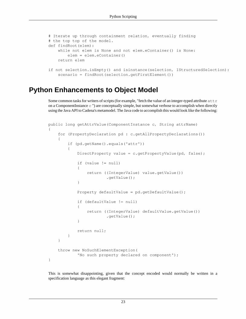
Python Enhancements to Object ModelSome common tasks for writers of scripts (for example, "fetch the value of an integer-typed attribute attron a ComponentInstance c ") are conceptually simple, but somewhat verbose to accomplish when directlyusing the Java API to Cadena's metamodel. The Java code to accomplish this would look like the following:
public long getAttrValue(ComponentInstance c, String attrName){ for (PropertyDeclaration pd : c.getAllPropertyDeclarations()) { if (pd.getName().equals("attr")) { DirectProperty value = c.getPropertyValue(pd, false); if (value != null) { return ((IntegerValue) value.getValue()) .getValue(); } Property defaultValue = pd.getDefaultValue(); if (defaultValue != null) { return ((IntegerValue) defaultValue.getValue()) .getValue(); } return null; } } throw new NoSuchElementException( "No such property declared on component");}
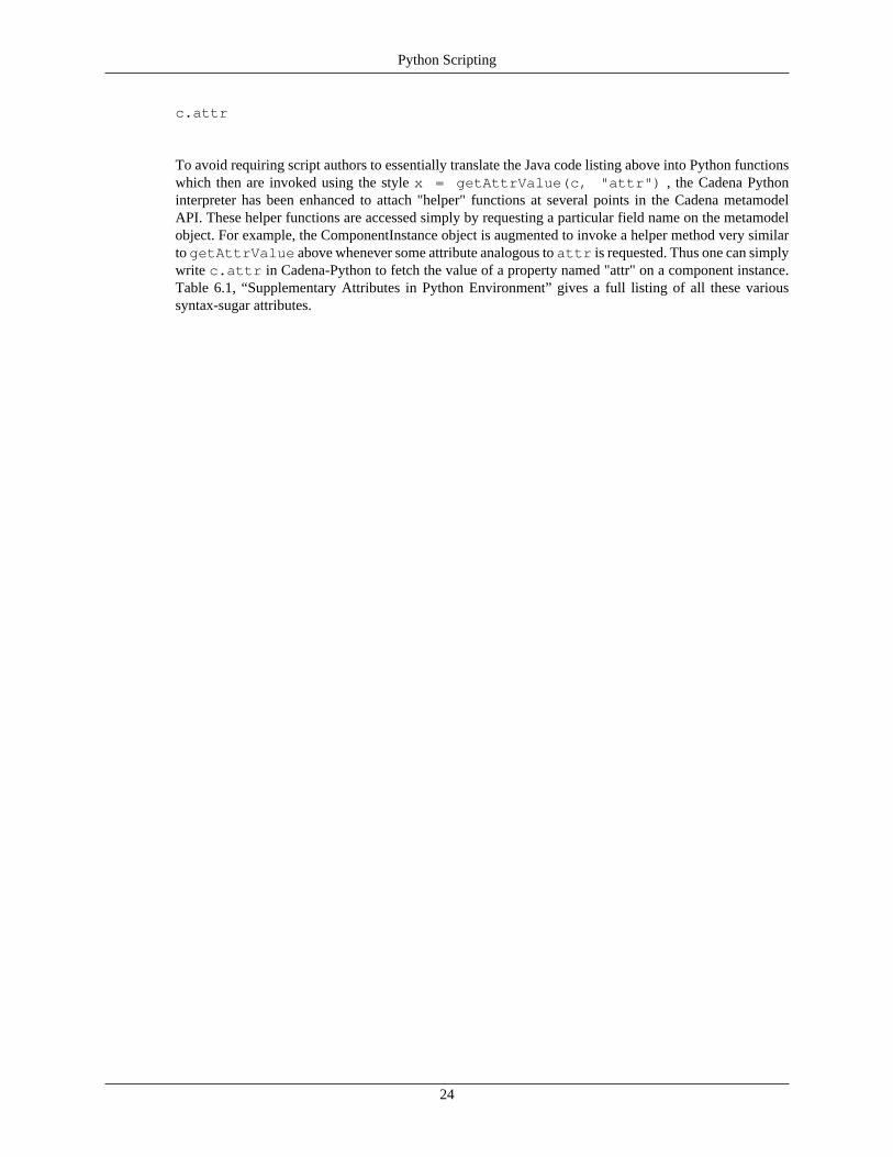
This is somewhat disappointing, given that the concept encoded would normally be written in aspecification language as this elegant fragment:
Python Scripting
24
c.attr
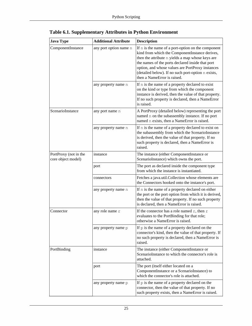
To avoid requiring script authors to essentially translate the Java code listing above into Python functionswhich then are invoked using the style x = getAttrValue(c, "attr") , the Cadena Pythoninterpreter has been enhanced to attach "helper" functions at several points in the Cadena metamodelAPI. These helper functions are accessed simply by requesting a particular field name on the metamodelobject. For example, the ComponentInstance object is augmented to invoke a helper method very similarto getAttrValue above whenever some attribute analogous to attr is requested. Thus one can simplywrite c.attr in Cadena-Python to fetch the value of a property named "attr" on a component instance.Table 6.1, “Supplementary Attributes in Python Environment” gives a full listing of all these varioussyntax-sugar attributes.
Python Scripting
25
Table 6.1. Supplementary Attributes in Python Environment
Java Type Additional Attribute Description
any port option name n If n is the name of a port-option on the componentkind from which the ComponentInstance derives,then the attribute n yields a map whose keys arethe names of the ports declared inside that portoption, and whose values are PortProxy instances(detailed below). If no such port-option n exists,then a NameError is raised.
ComponentInstance
any property name n If n is the name of a property declared to existon the kind or type from which the componentinstance is derived, then the value of that property.If no such property is declared, then a NameErroris raised.
any port name n A PortProxy (detailed below) representing the portnamed n on the subassembly instance. If no portnamed n exists, then a NameError is raised.
ScenarioInstance
any property name n If n is the name of a property declared to exist onthe subassembly from which the ScenarioInstanceis derived, then the value of that property. If nosuch property is declared, then a NameError israised.
instance The instance (either ComponentInstance orScenarioInstance) which owns the port.
port The port as declared inside the component typefrom which the instance is instantiated.
connectors Fetches a java.util.Collection whose elements arethe Connectors hooked onto the instance's port.
PortProxy (not in thecore object model)
any property name n If n is the name of a property declared on eitherthe port or the port option from which it is derived,then the value of that property. If no such propertyis declared, then a NameError is raised.
any role name r If the connector has a role named r, then revaluates to the PortBinding for that role;otherwise a NameError is raised.
Connector
any property name p If p is the name of a property declared on theconnector's kind, then the value of that property. Ifno such property is declared, then a NameError israised.
instance The instance (either ComponentInstance orScenarioInstance to which the connector's role isattached.
port The port (itself either located on aComponentInstance or a ScenarioInstance) towhich the connector's role is attached.
PortBinding
any property name p If p is the name of a property declared on theconnector, then the value of that property. If nosuch property exists, then a NameError is raised.
Python Scripting
26
Modifying the Model
Because the Java types which implement the Cadena metamodel are built using the Eclipse ModelingFramework, the pattern and style of methods used to change features of a model is very predictable: ifan object has some attribute attr , then a method setAttr will exist on its Java class. Modificationsto the model usually consist of nothing more than calling this mutator method with the new value passedas an argument.
Cadena imposes one extra requirement on changes to a model, though: all changes must be performedby a dedicated thread. One requests the model-change thread to execute a change by submitting a workerobject into a queue, then optionally blocking until the modification has been finished.
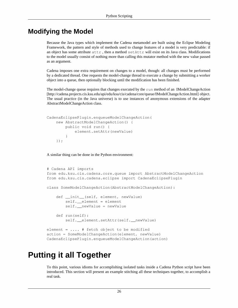
The model-change queue requires that changes executed by the run method of an IModelChangeAction[http://cadena.projects.cis.ksu.edu/api/edu/ksu/cis/cadena/core/queue/IModelChangeAction.html] object.The usual practice (in the Java universe) is to use instances of anonymous extensions of the adapterAbstractModelChangeAction class.
CadenaEclipsePlugin.enqueueModelChangeAction( new AbstractModelChangeAction() { public void run() { element.setAttr(newValue) } });
A similar thing can be done in the Python environment:
# Cadena API importsfrom edu.ksu.cis.cadena.core.queue import AbstractModelChangeActionfrom edu.ksu.cis.cadena.eclipse import CadenaEclipsePlugin
class SomeModelChangeAction(AbstractModelChangeAction):
def __init__(self, element, newValue) self.__element = element self.__newValue = newValue
def run(self): self.__element.setAttr(self.__newValue)
element = .... # fetch object to be modifiedaction = SomeModelChangeAction(element, newValue)CadenaEclipsePlugin.enqueueModelChangeAction(action)
Putting it all TogetherTo this point, various idioms for accomplishing isolated tasks inside a Cadena Python script have beenintroduced. This section will present an example stitching all these techniques together, to accomplish areal task.
Python Scripting
27
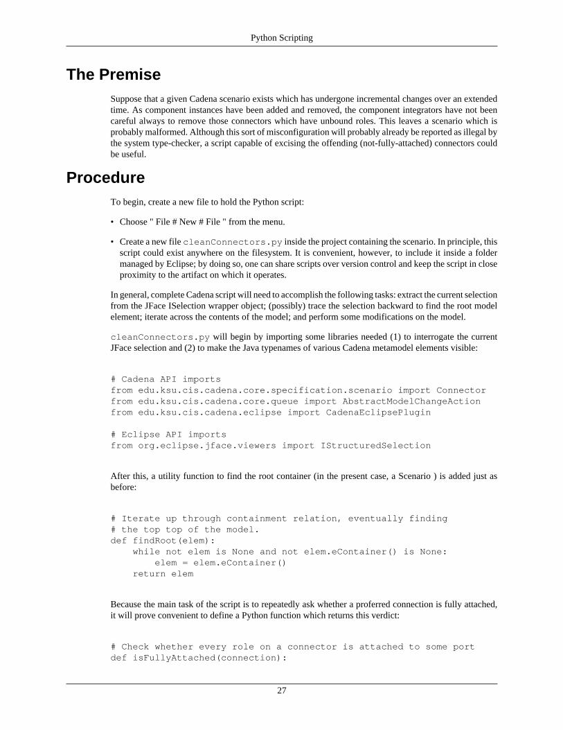
The PremiseSuppose that a given Cadena scenario exists which has undergone incremental changes over an extendedtime. As component instances have been added and removed, the component integrators have not beencareful always to remove those connectors which have unbound roles. This leaves a scenario which isprobably malformed. Although this sort of misconfiguration will probably already be reported as illegal bythe system type-checker, a script capable of excising the offending (not-fully-attached) connectors couldbe useful.
ProcedureTo begin, create a new file to hold the Python script:
• Choose " File # New # File " from the menu.
• Create a new file cleanConnectors.py inside the project containing the scenario. In principle, thisscript could exist anywhere on the filesystem. It is convenient, however, to include it inside a foldermanaged by Eclipse; by doing so, one can share scripts over version control and keep the script in closeproximity to the artifact on which it operates.
In general, complete Cadena script will need to accomplish the following tasks: extract the current selectionfrom the JFace ISelection wrapper object; (possibly) trace the selection backward to find the root modelelement; iterate across the contents of the model; and perform some modifications on the model.
cleanConnectors.py will begin by importing some libraries needed (1) to interrogate the currentJFace selection and (2) to make the Java typenames of various Cadena metamodel elements visible:
# Cadena API importsfrom edu.ksu.cis.cadena.core.specification.scenario import Connectorfrom edu.ksu.cis.cadena.core.queue import AbstractModelChangeActionfrom edu.ksu.cis.cadena.eclipse import CadenaEclipsePlugin
# Eclipse API importsfrom org.eclipse.jface.viewers import IStructuredSelection
After this, a utility function to find the root container (in the present case, a Scenario ) is added just asbefore:
# Iterate up through containment relation, eventually finding# the top top of the model.def findRoot(elem): while not elem is None and not elem.eContainer() is None: elem = elem.eContainer() return elem
Because the main task of the script is to repeatedly ask whether a proferred connection is fully attached,it will prove convenient to define a Python function which returns this verdict:
# Check whether every role on a connector is attached to some portdef isFullyAttached(connection):
Python Scripting
28
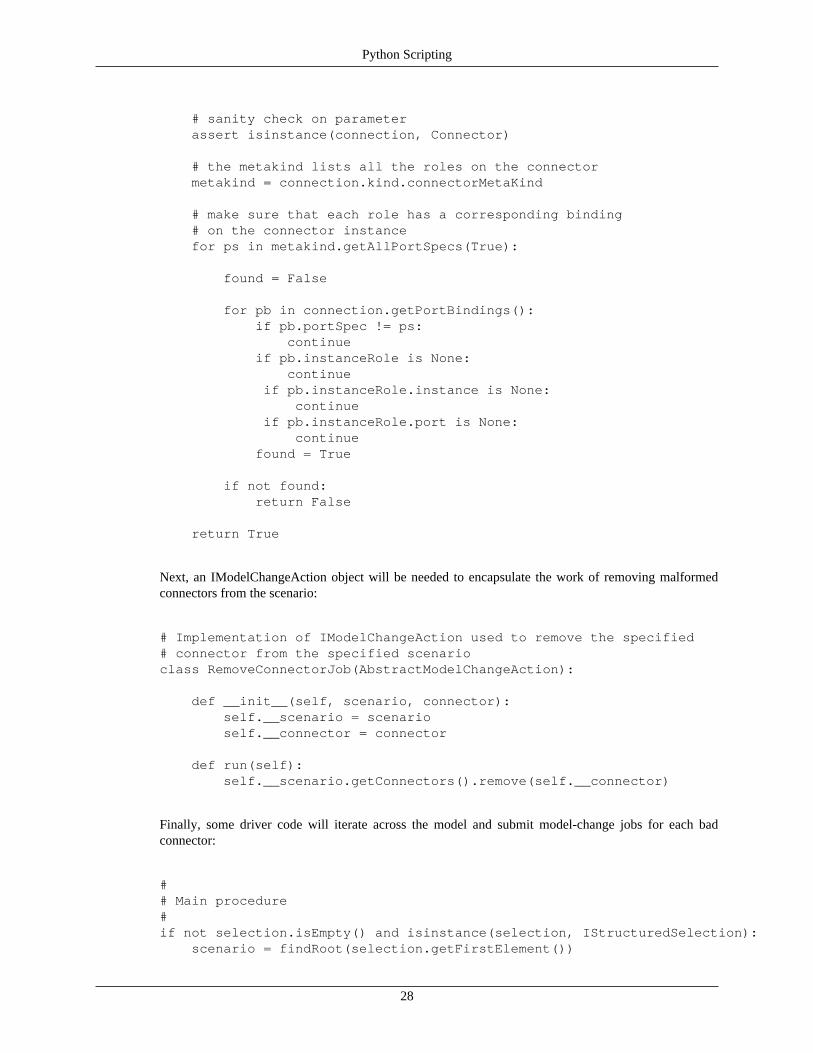
# sanity check on parameter assert isinstance(connection, Connector)
# the metakind lists all the roles on the connector metakind = connection.kind.connectorMetaKind # make sure that each role has a corresponding binding # on the connector instance for ps in metakind.getAllPortSpecs(True): found = False for pb in connection.getPortBindings(): if pb.portSpec != ps: continue if pb.instanceRole is None: continue if pb.instanceRole.instance is None: continue if pb.instanceRole.port is None: continue found = True if not found: return False return True
Next, an IModelChangeAction object will be needed to encapsulate the work of removing malformedconnectors from the scenario:
# Implementation of IModelChangeAction used to remove the specified# connector from the specified scenarioclass RemoveConnectorJob(AbstractModelChangeAction):
def __init__(self, scenario, connector): self.__scenario = scenario self.__connector = connector def run(self): self.__scenario.getConnectors().remove(self.__connector)
Finally, some driver code will iterate across the model and submit model-change jobs for each badconnector:
## Main procedure#if not selection.isEmpty() and isinstance(selection, IStructuredSelection): scenario = findRoot(selection.getFirstElement())
Python Scripting
29
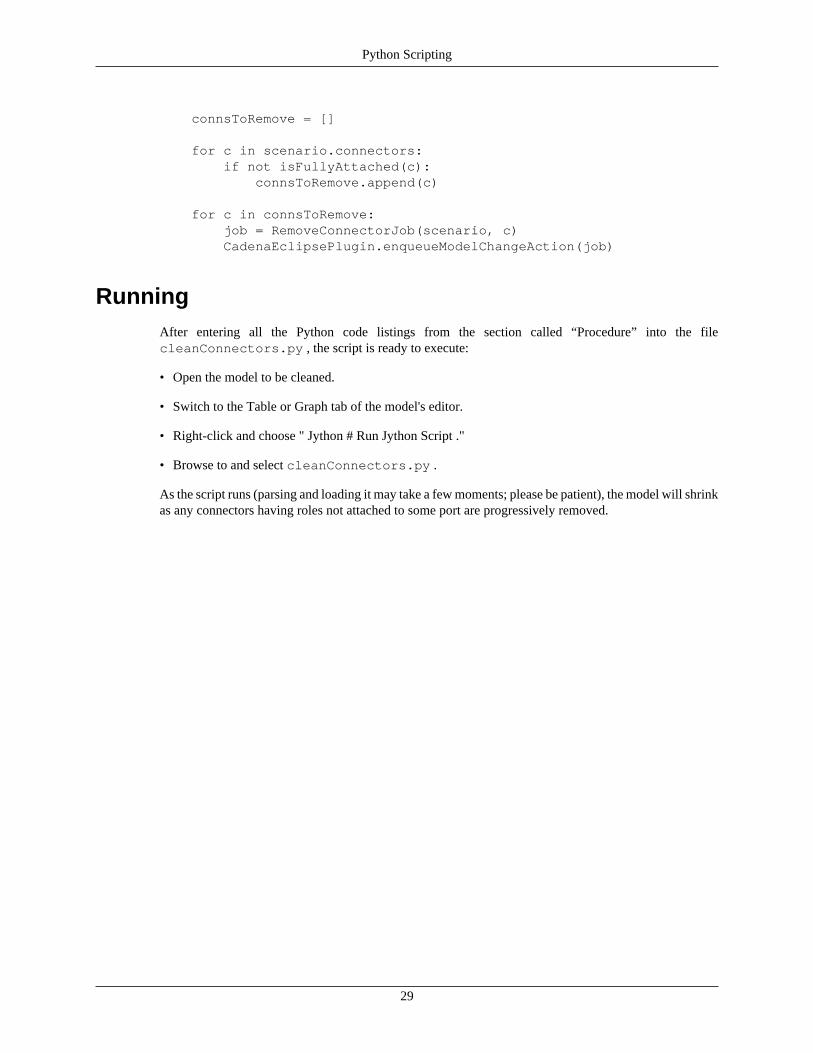
connsToRemove = [] for c in scenario.connectors: if not isFullyAttached(c): connsToRemove.append(c) for c in connsToRemove: job = RemoveConnectorJob(scenario, c) CadenaEclipsePlugin.enqueueModelChangeAction(job)
RunningAfter entering all the Python code listings from the section called “Procedure” into the filecleanConnectors.py , the script is ready to execute:
• Open the model to be cleaned.
• Switch to the Table or Graph tab of the model's editor.
• Right-click and choose " Jython # Run Jython Script ."
• Browse to and select cleanConnectors.py .
As the script runs (parsing and loading it may take a few moments; please be patient), the model will shrinkas any connectors having roles not attached to some port are progressively removed.

30
Chapter 7. Plug-In to CadenaOverview
Cadena is built using the Eclipse environment and framework. Because of that, it is very easy to enhanceand extend the features that Cadena currently has. This is done through the use of Eclipse plugins.
This section will try to explain and show how a developer can plug into Cadena using the Eclipse pluginframework. This section is not complete but should give developers a start.
In addition to this section of the manual, developers should also look into the sample projects that areavailable with each Cadena release. For example, we release the source for the OpenCCM/CCM and nesCplatform plugins for Cadena. In those two plugins, developers will find examples of styles, visual styles,actions, wizards, code generators, and much more.
Create a New PlatformOne of the ways that Cadena can be extended is by developing plugins for new platforms. For example,if a developer wants to deploy his application to a J2EE/EJB platform, a platform plugin would needto be written to facilitate that. The following section will provide some details on how this could beaccomplished.
This section will walk through creating a platform independent model (PIM) for use with sensor networks.The details of the language are as follows:
• There is a single component kind which has a single property named location.
• Each component instance will have a location associated with it.
• nesC Code will be generated that uses the location.
• There are three kinds of connectors.
• There are three kinds of interfaces.
• The PIM is very closely related to the nesC model so that it is easily translated to nesC.
With that in mind, we will walk through the following steps:
• Create a style that represents the specifications detail above.
• Create an Eclipse plugin for the platform.
• Add the style to the platform plugin.
• Add a visual style to the platform plugin.
• Prototype the code generation with a Jython script.
• Add an action to the platform plugin that will generate nesC code.
Create the StyleThe first step in creating a new Cadena platform is to create a style that describes the possibilities. Putanother way, you must describe the kinds of things available in this platform. This is done by describingwhat component, connector, and interface kinds that make up this platform. As mentioned before, we are
Plug-In to Cadena
31
trying to stay as close to the nesC model as possible so we will have 1 component kind, 3 connector kinds,and 3 interface kinds.
As you create the kinds keep in mind that Cadena expects each kind to have a meta-kind as a parent.Therefore, you should create the meta-kinds first and then create the kinds.
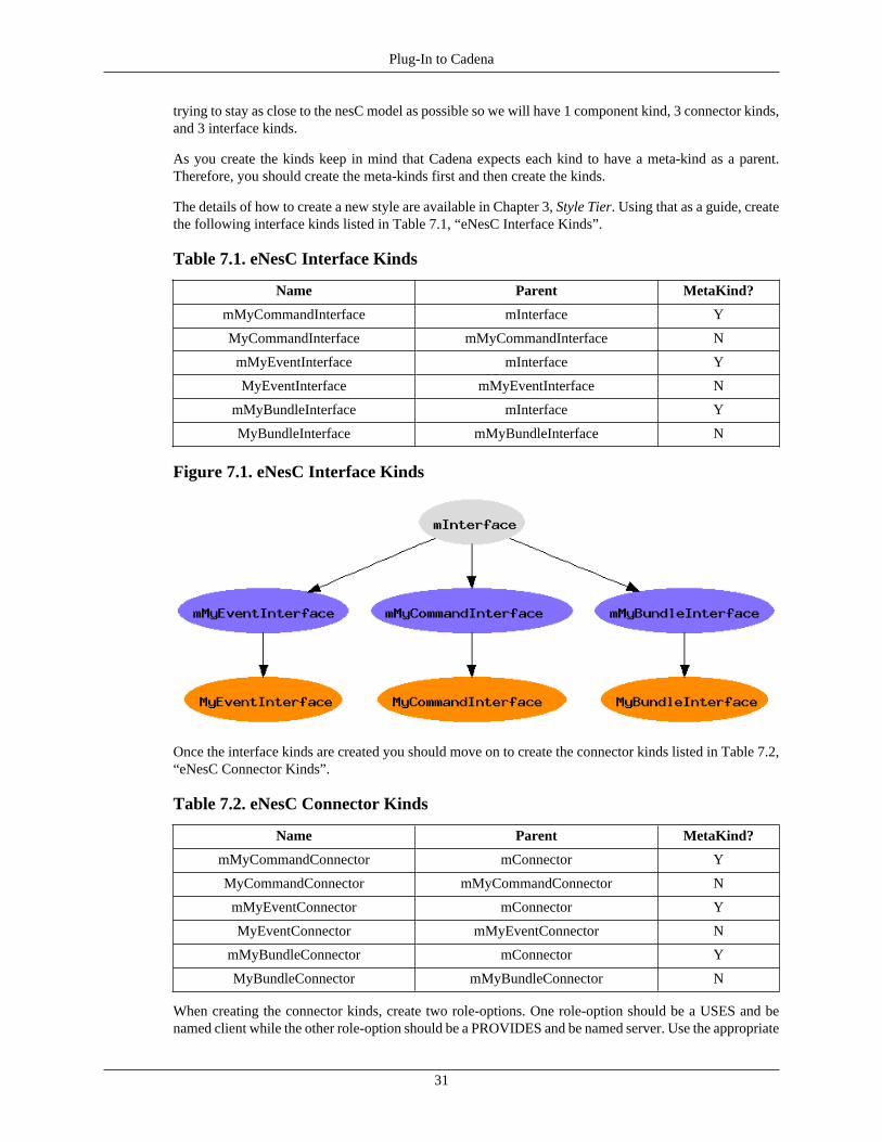
The details of how to create a new style are available in Chapter 3, Style Tier. Using that as a guide, createthe following interface kinds listed in Table 7.1, “eNesC Interface Kinds”.
Table 7.1. eNesC Interface Kinds
Name Parent MetaKind?
mMyCommandInterface mInterface Y
MyCommandInterface mMyCommandInterface N
mMyEventInterface mInterface Y
MyEventInterface mMyEventInterface N
mMyBundleInterface mInterface Y
MyBundleInterface mMyBundleInterface N
Figure 7.1. eNesC Interface Kinds
Once the interface kinds are created you should move on to create the connector kinds listed in Table 7.2,“eNesC Connector Kinds”.
Table 7.2. eNesC Connector Kinds
Name Parent MetaKind?
mMyCommandConnector mConnector Y
MyCommandConnector mMyCommandConnector N
mMyEventConnector mConnector Y
MyEventConnector mMyEventConnector N
mMyBundleConnector mConnector Y
MyBundleConnector mMyBundleConnector N
When creating the connector kinds, create two role-options. One role-option should be a USES and benamed client while the other role-option should be a PROVIDES and be named server. Use the appropriate
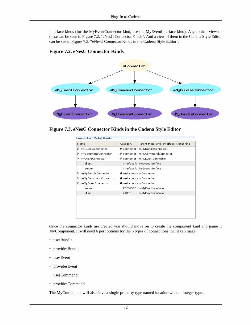
Plug-In to Cadena
32
interface kinds (for the MyEventConnector kind, use the MyEventInterface kind). A graphical view ofthese can be seen in Figure 7.2, “eNesC Connector Kinds”. And a view of them in the Cadena Style Editorcan be see in Figure 7.3, “eNesC Connector Kinds in the Cadena Style Editor”.
Figure 7.2. eNesC Connector Kinds
Figure 7.3. eNesC Connector Kinds in the Cadena Style Editor
Once the connector kinds are created you should move on to create the component kind and name itMyComponent. It will need 6 port options for the 6 types of connections that it can make.
• usesBundle
• providesBundle
• usesEvent
• providesEvent
• usesCommand
• providesCommand
The MyComponent will also have a single property type named location with an integer type.
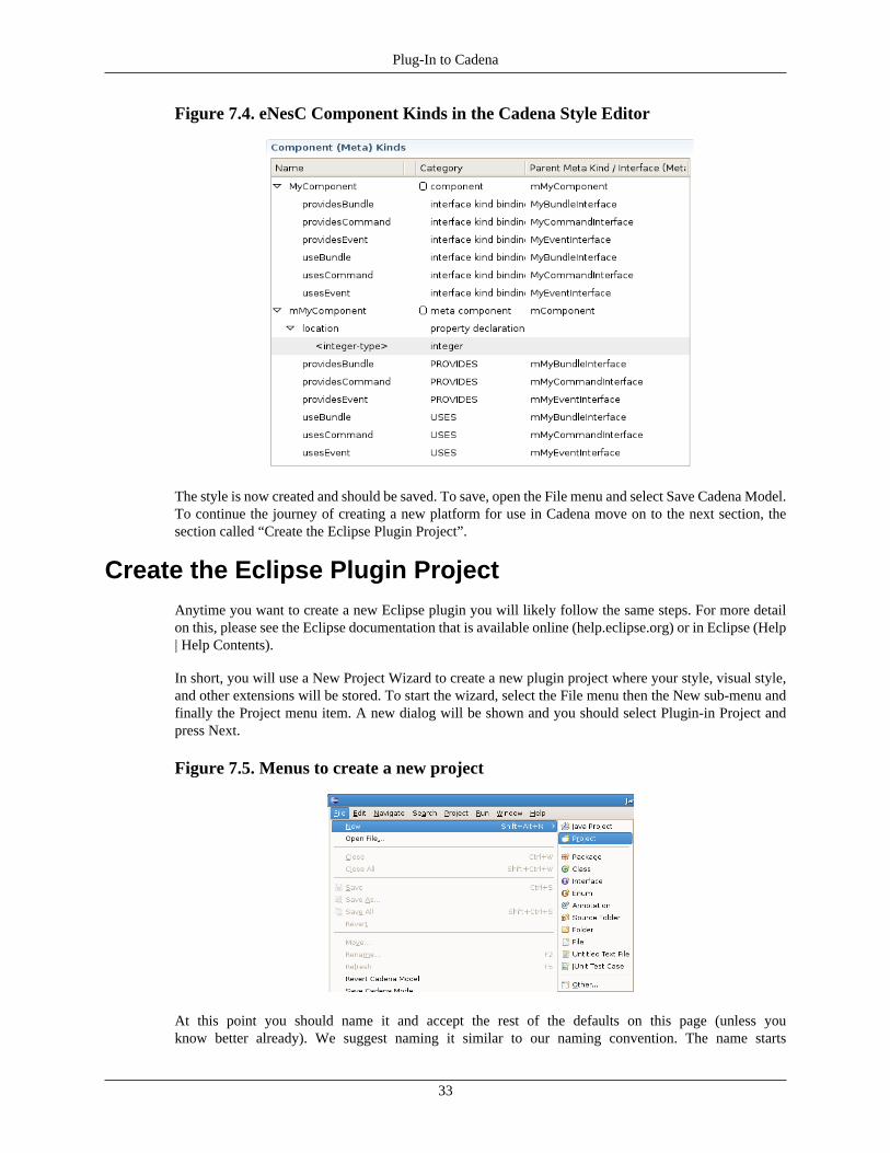
Plug-In to Cadena
33
Figure 7.4. eNesC Component Kinds in the Cadena Style Editor
The style is now created and should be saved. To save, open the File menu and select Save Cadena Model.To continue the journey of creating a new platform for use in Cadena move on to the next section, thesection called “Create the Eclipse Plugin Project”.
Create the Eclipse Plugin ProjectAnytime you want to create a new Eclipse plugin you will likely follow the same steps. For more detailon this, please see the Eclipse documentation that is available online (help.eclipse.org) or in Eclipse (Help| Help Contents).
In short, you will use a New Project Wizard to create a new plugin project where your style, visual style,and other extensions will be stored. To start the wizard, select the File menu then the New sub-menu andfinally the Project menu item. A new dialog will be shown and you should select Plugin-in Project andpress Next.
Figure 7.5. Menus to create a new project
At this point you should name it and accept the rest of the defaults on this page (unless youknow better already). We suggest naming it similar to our naming convention. The name starts
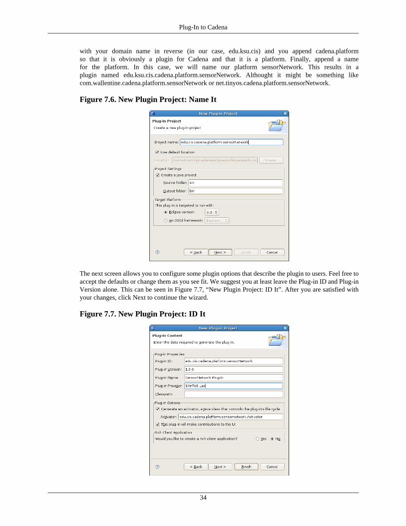
Plug-In to Cadena
34
with your domain name in reverse (in our case, edu.ksu.cis) and you append cadena.platformso that it is obviously a plugin for Cadena and that it is a platform. Finally, append a namefor the platform. In this case, we will name our platform sensorNetwork. This results in aplugin named edu.ksu.cis.cadena.platform.sensorNetwork. Althought it might be something likecom.wallentine.cadena.platform.sensorNetwork or net.tinyos.cadena.platform.sensorNetwork.
Figure 7.6. New Plugin Project: Name It
The next screen allows you to configure some plugin options that describe the plugin to users. Feel free toaccept the defaults or change them as you see fit. We suggest you at least leave the Plug-in ID and Plug-inVersion alone. This can be seen in Figure 7.7, “New Plugin Project: ID It”. After you are satisfied withyour changes, click Next to continue the wizard.
Figure 7.7. New Plugin Project: ID It
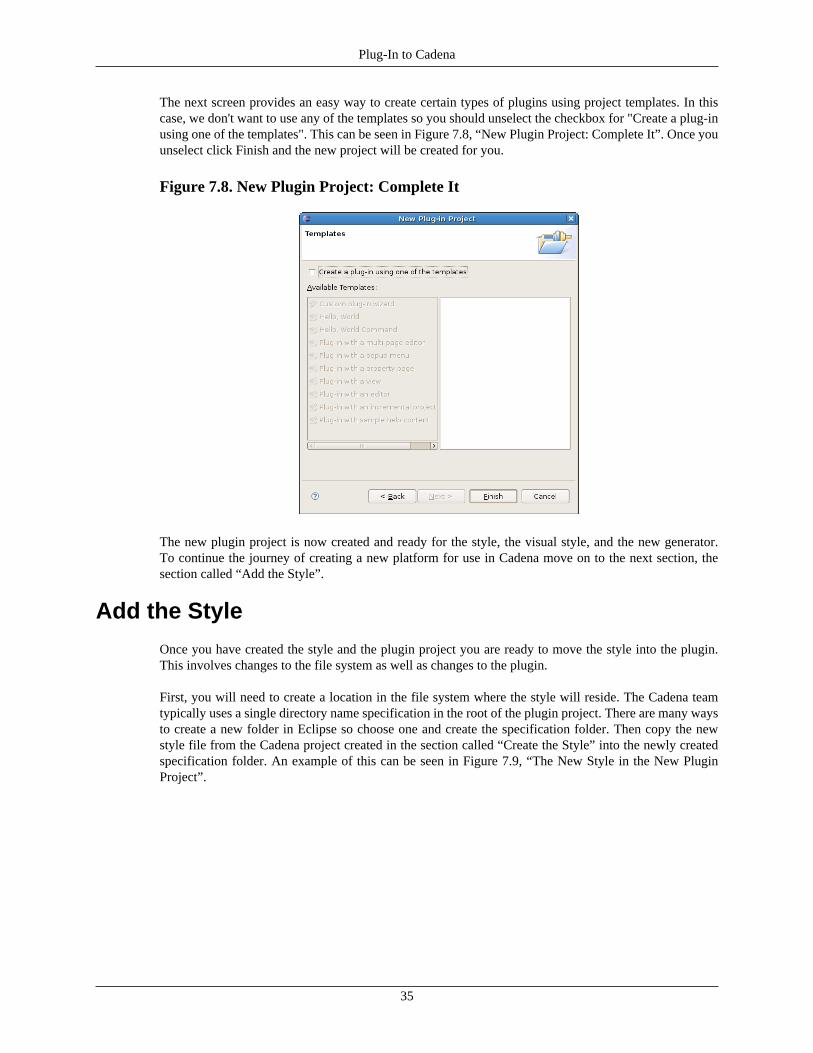
Plug-In to Cadena
35
The next screen provides an easy way to create certain types of plugins using project templates. In thiscase, we don't want to use any of the templates so you should unselect the checkbox for "Create a plug-inusing one of the templates". This can be seen in Figure 7.8, “New Plugin Project: Complete It”. Once youunselect click Finish and the new project will be created for you.
Figure 7.8. New Plugin Project: Complete It
The new plugin project is now created and ready for the style, the visual style, and the new generator.To continue the journey of creating a new platform for use in Cadena move on to the next section, thesection called “Add the Style”.
Add the Style
Once you have created the style and the plugin project you are ready to move the style into the plugin.This involves changes to the file system as well as changes to the plugin.
First, you will need to create a location in the file system where the style will reside. The Cadena teamtypically uses a single directory name specification in the root of the plugin project. There are many waysto create a new folder in Eclipse so choose one and create the specification folder. Then copy the newstyle file from the Cadena project created in the section called “Create the Style” into the newly createdspecification folder. An example of this can be seen in Figure 7.9, “The New Style in the New PluginProject”.
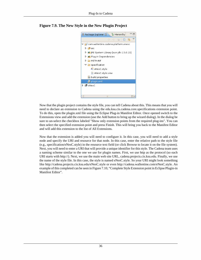
Plug-In to Cadena
36
Figure 7.9. The New Style in the New Plugin Project
Now that the plugin project contains the style file, you can tell Cadena about this. This means that you willneed to declare an extension to Cadena using the edu.ksu.cis.cadena.core.specifications extension point.To do this, open the plugin.xml file using the Eclipse Plug-in Manifest Editor. Once opened switch to theExtensions view and add the extension (use the Add button to bring up the wizard dialog). In the dialog besure to un-select the checkbox labeled "Show only extension points from the required plug-ins". You canthen select the specified extension point and press Finish. This will bring you back to the Manifest Editorand will add this extension to the list of All Extensions.
Now that the extension is added you will need to configure it. In this case, you will need to add a stylenode and specify the URI and resource for that node. In this case, enter the relative path to the style file(e.g., specification/eNesC.style) in the resource text field (or click Browse to locate it on the file system).Next, you will need to enter a URI that will provide a unique identifier for this style. The Cadena team usesa naming scheme similar to the one we use for plugin names. First, we use http as the protocol (so eachURI starts with http://). Next, we use the main web site URL, cadena.projects.cis.ksu.edu. Finally, we usethe name of the style file. In this case, the style is named eNesC.style. So your URI might look somethinglike http://cadena.projects.cis.ksu.edu/eNesC.style or even http://cadena.wallentine.com/eNesC.style. Anexample of this completed can be seen in Figure 7.10, “Complete Style Extension point in Eclipse Plugin-inManifest Editor”.
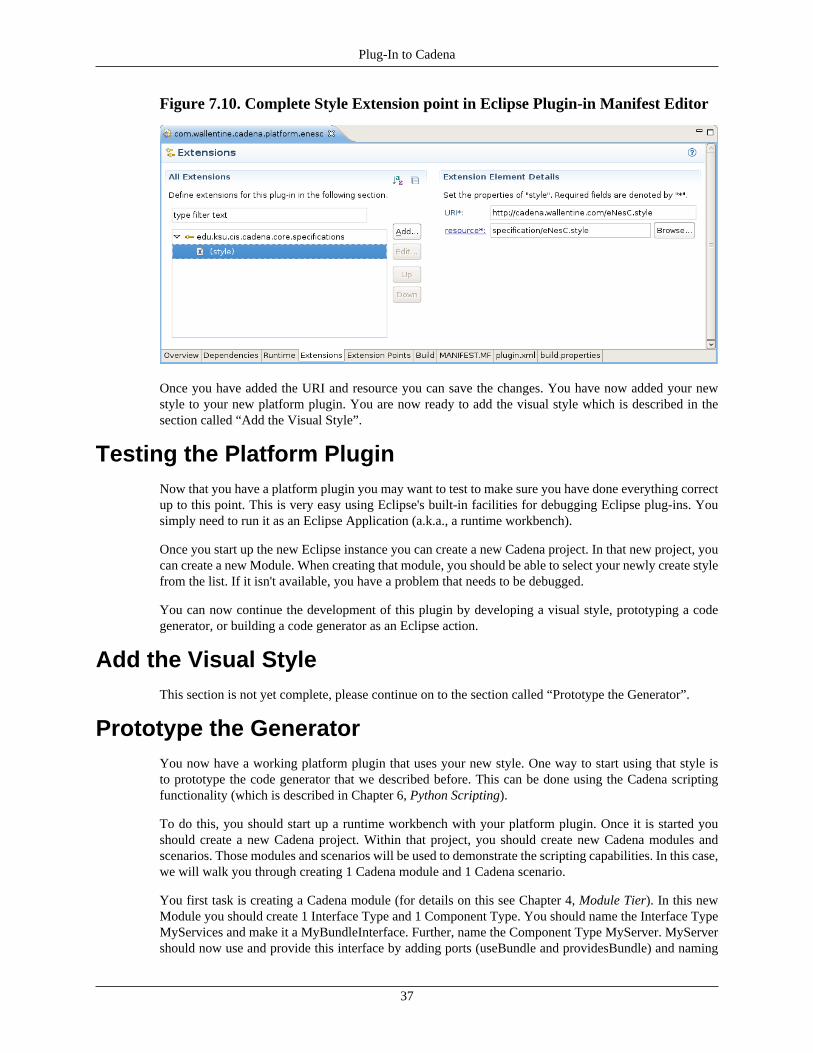
Plug-In to Cadena
37
Figure 7.10. Complete Style Extension point in Eclipse Plugin-in Manifest Editor
Once you have added the URI and resource you can save the changes. You have now added your newstyle to your new platform plugin. You are now ready to add the visual style which is described in thesection called “Add the Visual Style”.
Testing the Platform PluginNow that you have a platform plugin you may want to test to make sure you have done everything correctup to this point. This is very easy using Eclipse's built-in facilities for debugging Eclipse plug-ins. Yousimply need to run it as an Eclipse Application (a.k.a., a runtime workbench).
Once you start up the new Eclipse instance you can create a new Cadena project. In that new project, youcan create a new Module. When creating that module, you should be able to select your newly create stylefrom the list. If it isn't available, you have a problem that needs to be debugged.
You can now continue the development of this plugin by developing a visual style, prototyping a codegenerator, or building a code generator as an Eclipse action.
Add the Visual StyleThis section is not yet complete, please continue on to the section called “Prototype the Generator”.
Prototype the GeneratorYou now have a working platform plugin that uses your new style. One way to start using that style isto prototype the code generator that we described before. This can be done using the Cadena scriptingfunctionality (which is described in Chapter 6, Python Scripting).
To do this, you should start up a runtime workbench with your platform plugin. Once it is started youshould create a new Cadena project. Within that project, you should create new Cadena modules andscenarios. Those modules and scenarios will be used to demonstrate the scripting capabilities. In this case,we will walk you through creating 1 Cadena module and 1 Cadena scenario.
You first task is creating a Cadena module (for details on this see Chapter 4, Module Tier). In this newModule you should create 1 Interface Type and 1 Component Type. You should name the Interface TypeMyServices and make it a MyBundleInterface. Further, name the Component Type MyServer. MyServershould now use and provide this interface by adding ports (useBundle and providesBundle) and naming
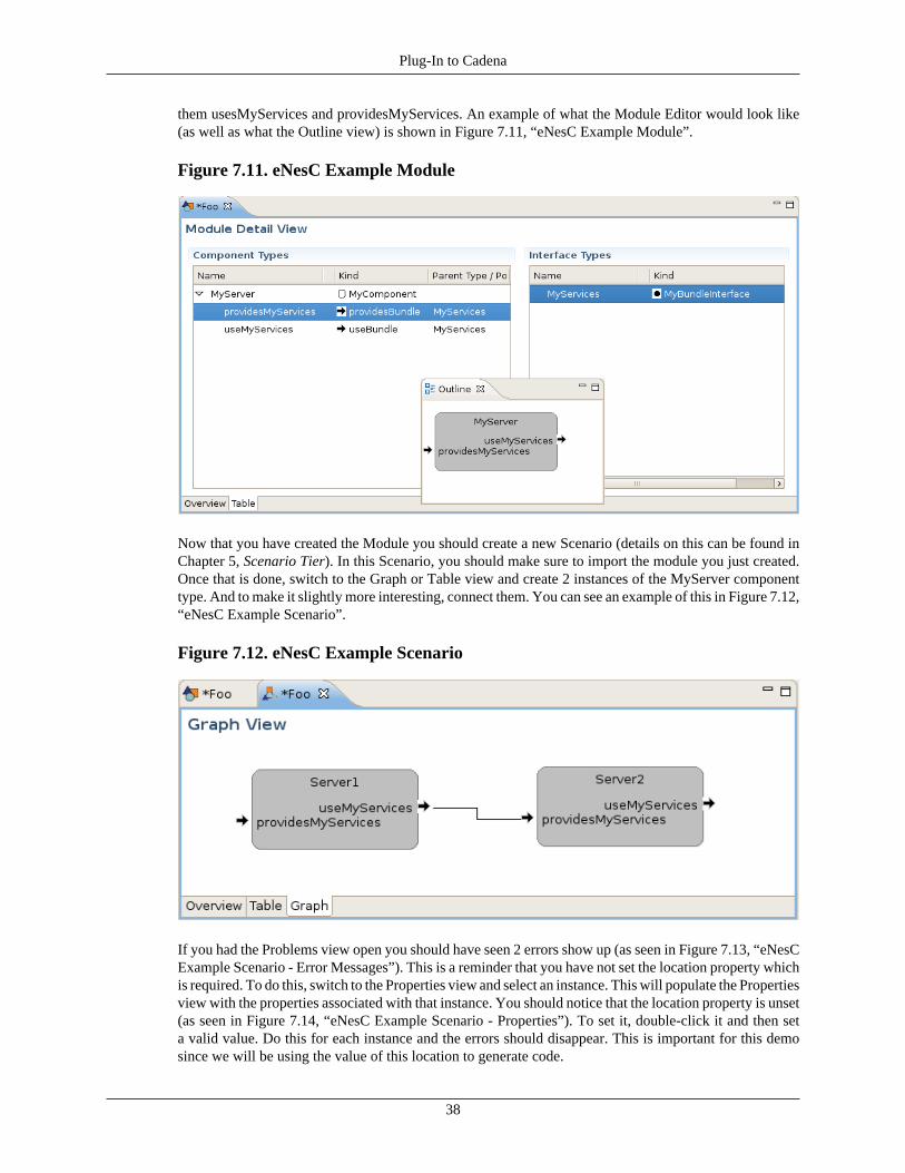
Plug-In to Cadena
38
them usesMyServices and providesMyServices. An example of what the Module Editor would look like(as well as what the Outline view) is shown in Figure 7.11, “eNesC Example Module”.
Figure 7.11. eNesC Example Module
Now that you have created the Module you should create a new Scenario (details on this can be found inChapter 5, Scenario Tier). In this Scenario, you should make sure to import the module you just created.Once that is done, switch to the Graph or Table view and create 2 instances of the MyServer componenttype. And to make it slightly more interesting, connect them. You can see an example of this in Figure 7.12,“eNesC Example Scenario”.
Figure 7.12. eNesC Example Scenario
If you had the Problems view open you should have seen 2 errors show up (as seen in Figure 7.13, “eNesCExample Scenario - Error Messages”). This is a reminder that you have not set the location property whichis required. To do this, switch to the Properties view and select an instance. This will populate the Propertiesview with the properties associated with that instance. You should notice that the location property is unset(as seen in Figure 7.14, “eNesC Example Scenario - Properties”). To set it, double-click it and then seta valid value. Do this for each instance and the errors should disappear. This is important for this demosince we will be using the value of this location to generate code.
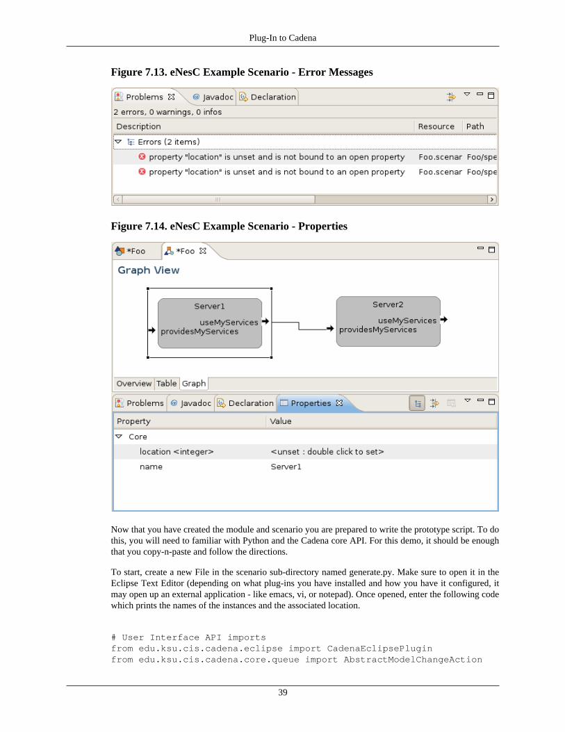
Plug-In to Cadena
39
Figure 7.13. eNesC Example Scenario - Error Messages
Figure 7.14. eNesC Example Scenario - Properties
Now that you have created the module and scenario you are prepared to write the prototype script. To dothis, you will need to familiar with Python and the Cadena core API. For this demo, it should be enoughthat you copy-n-paste and follow the directions.
To start, create a new File in the scenario sub-directory named generate.py. Make sure to open it in theEclipse Text Editor (depending on what plug-ins you have installed and how you have it configured, itmay open up an external application - like emacs, vi, or notepad). Once opened, enter the following codewhich prints the names of the instances and the associated location.
# User Interface API importsfrom edu.ksu.cis.cadena.eclipse import CadenaEclipsePluginfrom edu.ksu.cis.cadena.core.queue import AbstractModelChangeAction

Plug-In to Cadena
40
# Eclipse API importsfrom org.eclipse.emf.ecore import EObjectfrom org.eclipse.jface.viewers import IStructuredSelection
# Miscellaneous Java library importsfrom java.lang import Runnable, Thread
## Fetch the root EObject from the JFace current selection#def fetchRoot(selection): if selection is None or selection.isEmpty(): return None elif not isinstance(selection, IStructuredSelection): return None elif isinstance(selection.firstElement, EObject): root = selection.firstElement while not root is None and not root.eContainer() is None: root = root.eContainer() return root
# Get the location property value from the given instance. It is# assumed that the name of the property is location and it has# a type of IntegerValue. Therefore, the return type is Long (java.lang).def getLocation(instance): propertyDeclaration = fetchPropertyDeclaration(instance, "location") if(propertyDeclaration != None): directProperty = instance.getPropertyValue(propertyDeclaration, 0) if(directProperty != None): propertyValue = directProperty.getValue() if(propertyValue != None): return propertyValue.getValue() return None
# Fetch the property declaration from the given instance that has# the given property name. The type of the returned object will# a PropertyDeclaration (edu.ksu.cis.cadena.core.specification.property).def fetchPropertyDeclaration(instance, name): for propertyDeclaration in instance.getAllPropertyDeclarations(): if name == propertyDeclaration.getName(): return propertyDeclaration return None
# Main Logic: Walk through the scenario and print the name of the instance# and what location it should be deployed to.# first, we need to get the scenarioscenario = fetchRoot(selection)
# next, we will collect up the component and scenario instancesfor instance in scenario.allInstances: location = getLocation(instance)
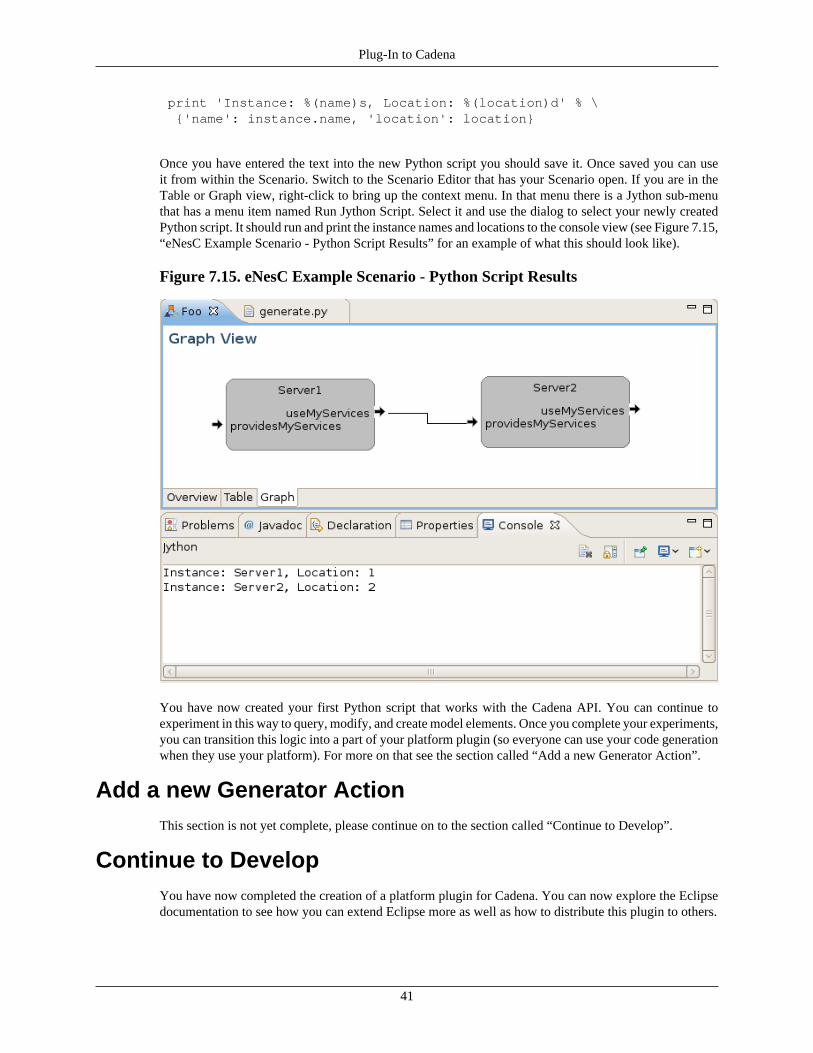
Plug-In to Cadena
41
print 'Instance: %(name)s, Location: %(location)d' % \ {'name': instance.name, 'location': location}
Once you have entered the text into the new Python script you should save it. Once saved you can useit from within the Scenario. Switch to the Scenario Editor that has your Scenario open. If you are in theTable or Graph view, right-click to bring up the context menu. In that menu there is a Jython sub-menuthat has a menu item named Run Jython Script. Select it and use the dialog to select your newly createdPython script. It should run and print the instance names and locations to the console view (see Figure 7.15,“eNesC Example Scenario - Python Script Results” for an example of what this should look like).
Figure 7.15. eNesC Example Scenario - Python Script Results
You have now created your first Python script that works with the Cadena API. You can continue toexperiment in this way to query, modify, and create model elements. Once you complete your experiments,you can transition this logic into a part of your platform plugin (so everyone can use your code generationwhen they use your platform). For more on that see the section called “Add a new Generator Action”.
Add a new Generator ActionThis section is not yet complete, please continue on to the section called “Continue to Develop”.
Continue to DevelopYou have now completed the creation of a platform plugin for Cadena. You can now explore the Eclipsedocumentation to see how you can extend Eclipse more as well as how to distribute this plugin to others.
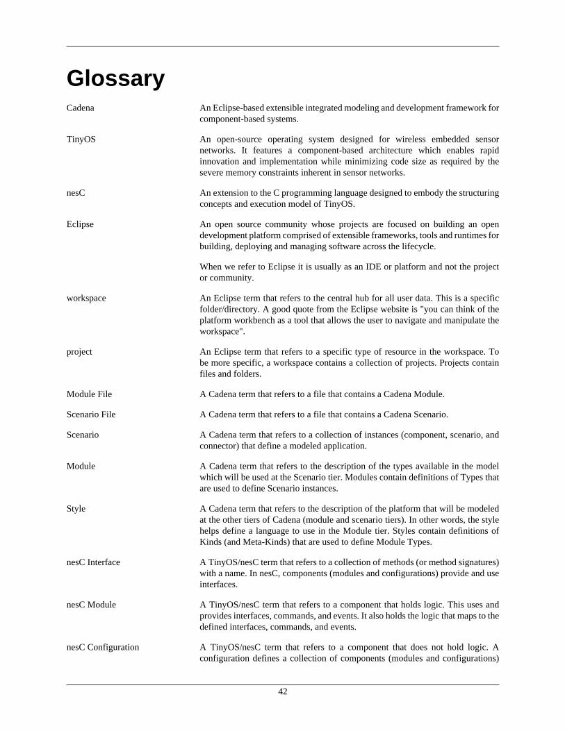
42
GlossaryCadena An Eclipse-based extensible integrated modeling and development framework for
component-based systems.
TinyOS An open-source operating system designed for wireless embedded sensornetworks. It features a component-based architecture which enables rapidinnovation and implementation while minimizing code size as required by thesevere memory constraints inherent in sensor networks.
nesC An extension to the C programming language designed to embody the structuringconcepts and execution model of TinyOS.
Eclipse An open source community whose projects are focused on building an opendevelopment platform comprised of extensible frameworks, tools and runtimes forbuilding, deploying and managing software across the lifecycle.
When we refer to Eclipse it is usually as an IDE or platform and not the projector community.
workspace An Eclipse term that refers to the central hub for all user data. This is a specificfolder/directory. A good quote from the Eclipse website is "you can think of theplatform workbench as a tool that allows the user to navigate and manipulate theworkspace".
project An Eclipse term that refers to a specific type of resource in the workspace. Tobe more specific, a workspace contains a collection of projects. Projects containfiles and folders.
Module File A Cadena term that refers to a file that contains a Cadena Module.
Scenario File A Cadena term that refers to a file that contains a Cadena Scenario.
Scenario A Cadena term that refers to a collection of instances (component, scenario, andconnector) that define a modeled application.
Module A Cadena term that refers to the description of the types available in the modelwhich will be used at the Scenario tier. Modules contain definitions of Types thatare used to define Scenario instances.
Style A Cadena term that refers to the description of the platform that will be modeledat the other tiers of Cadena (module and scenario tiers). In other words, the stylehelps define a language to use in the Module tier. Styles contain definitions ofKinds (and Meta-Kinds) that are used to define Module Types.
nesC Interface A TinyOS/nesC term that refers to a collection of methods (or method signatures)with a name. In nesC, components (modules and configurations) provide and useinterfaces.
nesC Module A TinyOS/nesC term that refers to a component that holds logic. This uses andprovides interfaces, commands, and events. It also holds the logic that maps to thedefined interfaces, commands, and events.
nesC Configuration A TinyOS/nesC term that refers to a component that does not hold logic. Aconfiguration defines a collection of components (modules and configurations)
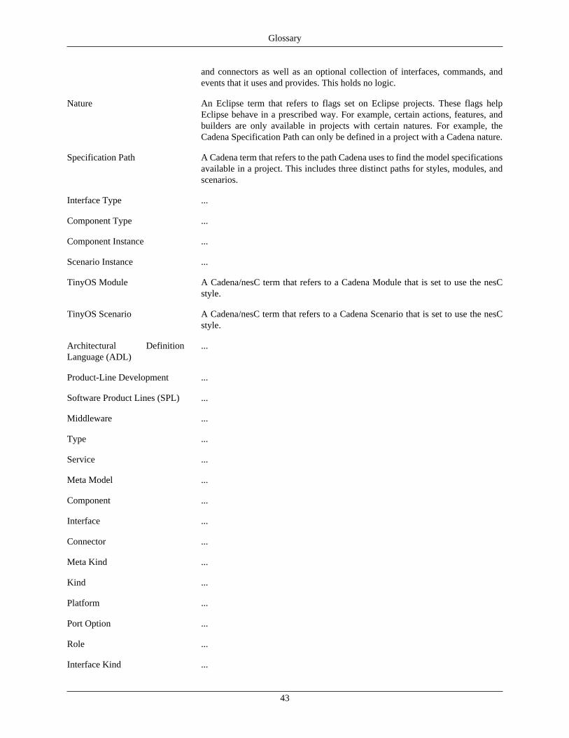
Glossary
43
and connectors as well as an optional collection of interfaces, commands, andevents that it uses and provides. This holds no logic.
Nature An Eclipse term that refers to flags set on Eclipse projects. These flags helpEclipse behave in a prescribed way. For example, certain actions, features, andbuilders are only available in projects with certain natures. For example, theCadena Specification Path can only be defined in a project with a Cadena nature.
Specification Path A Cadena term that refers to the path Cadena uses to find the model specificationsavailable in a project. This includes three distinct paths for styles, modules, andscenarios.
Interface Type ...
Component Type ...
Component Instance ...
Scenario Instance ...
TinyOS Module A Cadena/nesC term that refers to a Cadena Module that is set to use the nesCstyle.
TinyOS Scenario A Cadena/nesC term that refers to a Cadena Scenario that is set to use the nesCstyle.
Architectural DefinitionLanguage (ADL)
...
Product-Line Development ...
Software Product Lines (SPL) ...
Middleware ...
Type ...
Service ...
Meta Model ...
Component ...
Interface ...
Connector ...
Meta Kind ...
Kind ...
Platform ...
Port Option ...
Role ...
Interface Kind ...
Glossary
44
Component Kind ...
Connector Kind ...
Instance ...
Level ...
Layer ...
Assembly ...

45
Bibliography[Eclipse:URL] Eclipse . “{Eclipse} Website”. 2001.
[nesC:URL] “nesC Web Site”.
[TinyOS:URL] “TinyOS Web Site”.
[Cadena:URL] “{\sc Cadena} Web Site”.