cafcr: a multi-view method for embedded systems architecting
TRANSCRIPT

CAFCR: A Multi-view Method forEmbedded Systems Architecting;
Balancing Genericity and Specificity
t recon =
n raw- x * ( t fft (n raw-y )
n y * ( t fft (n raw-x )
t filter ( n raw-x ,n raw-y ) +
+ +
t col-overhead
t corrections ( n x ,n y )
t row -overhead
t control -overhead
+
) +
) +
Gerrit Muller

ii
This page will not be present in the final thesis
version: 2.9 status: concept date: March 6, 2013

iii
CAFCR: A Multi-view Method for Embedded Systems Architecting;Balancing Genericity and Specificity
Proefschrift
ter verkrijging van de graad van doctoraan de Technische Universiteit Delft,
op gezag van de Rector Magnificus prof.dr.ir. J.T. Fokkema,voorzitter van het College voor Promoties,
in het openbaar te verdedigen op maandag 7 juni 2004 om 13:00 uurdoor Gerrit Jan MULLER
doctorandus in de natuurkundegeboren te Amsterdam

iv
Dit proefschrift is goedgekeurd door de promotor:Prof.dr W.G. Vree
Samenstelling promotiecommissie:
Rector Magnificus voorzitterProf.dr. W.G. Vree Technische Universiteit Delft, promotorProf.dr. M. Rem Technische Universiteit EindhovenProf.dr.ir. P.A. Kroes Technische Universiteit DelftProf.dr.ir. H.J. Sips Technische Universiteit DelftProf.dr. R. Wagenaar Technische Universiteit DelftProf.dr.ing. D.K. Hammer Technische Universiteit EindhovenProf.dr. P.H. Hartel Universiteit Twente
Prof.dr. M. Rem heeft als begeleider in belangrijke mate aan detotstandkoming van het proefschrift bijgedragen.
ISBN 90-5639-120-2
Keywords: Systems Architecture, System design, Systems Engineering
These investigations were supported by Philips Research Laboratories, and the EmbeddedSystems Institute, both in Eindhoven.
Cover Photograph: René Stout http://www.rwstout.com/
Copyright c©2004 by G.J. Muller. This thesis is written as part of the Gaudí project.Further distribution is allowed as long as the thesis remains complete and unchanged.Use of figures is allowed as long as a reference to the source is present. Note that thecopyright of photographs resides at the original copyright owners.
Preface
The industrial world and the academic world have drifted far apart in the imma-ture discipline of systems architecting. The challenge in writing this thesis was tocapture the industrial pragmatic experience in a way that is acceptable for the aca-demic community. Moreover, the Embedded Systems Institute has the ambitionto mature and extend this discipline. This thesis is a first step in bridging the gapbetween industry and academics.
The personal motivation for writing this thesis is best explained by lookingback at my career. I have been active in the hectic product creation environmentfor about twenty years. More than 17 years I was responsible for several archi-tectures of medical systems. The drawing on the cover has been made in thisperiod to visualize the system designer as a monster with twenty heads, and hencetwenty viewpoints. For more than two years I have been heading the Systems En-gineering department at ASML. This period at ASML was very instructive andrefreshing. I very much liked the opportunity to educate and coach future as wellas senior system engineers in this young discipline. After these twenty years ofindustrial pressure I joined Philips Research, with as my personal goal to maturethe discipline and to make it more accessible and transferable. The Gaudí sitewww.gaudisite.nl/ shows the ongoing results of this effort. The step fromPhilips Research to the Embedded Systems Institute1 creates the opportunity tolink this experience based work to the academic world.
One of the peculiarities of the academic world is that only people with a doc-tor’s title seem to be taken seriously. In the process of writing this thesis I havehit many more aspects of the scientific culture, such as the need to cite others forevery statement being made, an extremely redundant writing style, the preferencefor text over figures, and a focus on the argumentation rather than on the clar-ity or didactic value. Going through this learning experience is very valuable in
1 The Embedded Systems Institute is founded by Philips, ASML, Océ, TNO and the universitiesof Delft, Eindhoven and Twente
v

vi PREFACE
the interaction with the academic world. I gained a better understanding of theobsession for publication, peer review, and the noise induced by all citations andrepetitions in scientific publications. Understanding the motivation and the behav-ior of the academic partners is a prerequisite to bridge the gap between industryand academics.
My thinking processes make use of visualizations: diagrams, structures, mod-els, et cetera. This thesis contains over 150 figures. The advantage of figures isthat they show the overview and the parts at the same time, whereas text is linear:only after reading the entire text the overview might become clear. Lots of energyhas been spent to complement all visualizations with readable text.
The broad and multi-disciplinary scope of systems architecting can easily re-sult in generic statements. I have attempted to cope with this danger of over-generalization by providing a very specific case study. This struggle with thebalance between genericity and specificity is the daily world of every systems ar-chitect. This struggle repeated itself when writing this thesis. The academic valueis in the extraction of more generally applicable knowledge. But the route towardsthis knowledge meanders through many highly specific details.
If both academic people as well as industrial people enjoy reading this thesisthen one of my goals has been achieved. So, enjoy reading!
Contents
Preface v
Introduction xi
I Introduction to CAFCR and Threads of Reasoning 1
1 What is Systems Architecting in an Industrial Context? 31.1 Introduction . . . . . . . . . . . . . . . . . . . . . . . . . . . . . 31.2 Description of the Business Context . . . . . . . . . . . . . . . . 51.3 Internal Stakeholders . . . . . . . . . . . . . . . . . . . . . . . . 51.4 Acknowledgements . . . . . . . . . . . . . . . . . . . . . . . . . 6
2 Overview of CAFCR and Threads of Reasoning 72.1 Introduction . . . . . . . . . . . . . . . . . . . . . . . . . . . . . 72.2 Architecting Method Overview . . . . . . . . . . . . . . . . . . . 72.3 The CAFCR Model . . . . . . . . . . . . . . . . . . . . . . . . . 8
3 Introduction to Medical Imaging Case Study 133.1 Market and Application . . . . . . . . . . . . . . . . . . . . . . . 133.2 Technology . . . . . . . . . . . . . . . . . . . . . . . . . . . . . 15
4 Positioning the CAFCR Method in the World 194.1 Introduction . . . . . . . . . . . . . . . . . . . . . . . . . . . . . 194.2 Related Work . . . . . . . . . . . . . . . . . . . . . . . . . . . . 194.3 What is the Unique Contribution of this Work? . . . . . . . . . . 224.4 IEEE 1471 . . . . . . . . . . . . . . . . . . . . . . . . . . . . . . 24
vii
viii CONTENTS
5 Research in Systems Architecting 275.1 Introduction . . . . . . . . . . . . . . . . . . . . . . . . . . . . . 275.2 Technology Management Cycle . . . . . . . . . . . . . . . . . . 285.3 Challenges to do Research in a Scientific Way . . . . . . . . . . . 295.4 Architecting Research Method . . . . . . . . . . . . . . . . . . . 335.5 Distance between Industrial Practice and Scientific Research . . . 345.6 Research Environment . . . . . . . . . . . . . . . . . . . . . . . 35
6 Research Question and Hypothesis 376.1 Introduction . . . . . . . . . . . . . . . . . . . . . . . . . . . . . 376.2 Research Question . . . . . . . . . . . . . . . . . . . . . . . . . 376.3 Hypothesis . . . . . . . . . . . . . . . . . . . . . . . . . . . . . 396.4 Criteria . . . . . . . . . . . . . . . . . . . . . . . . . . . . . . . 416.5 Summary . . . . . . . . . . . . . . . . . . . . . . . . . . . . . . 42
II Theory of CAFCR and Threads of Reasoning 43
7 Basic Methods 457.1 Introduction . . . . . . . . . . . . . . . . . . . . . . . . . . . . . 457.2 Viewpoint Hopping . . . . . . . . . . . . . . . . . . . . . . . . . 467.3 Decomposition and Integration . . . . . . . . . . . . . . . . . . . 497.4 Quantification . . . . . . . . . . . . . . . . . . . . . . . . . . . . 497.5 Coping with Uncertainty . . . . . . . . . . . . . . . . . . . . . . 517.6 Modeling . . . . . . . . . . . . . . . . . . . . . . . . . . . . . . 527.7 WWHWWW . . . . . . . . . . . . . . . . . . . . . . . . . . . . 537.8 Decision Making Approach in Specification and Design . . . . . . 54
8 Submethods in the CAF Views 598.1 Introduction . . . . . . . . . . . . . . . . . . . . . . . . . . . . . 598.2 Key Drivers . . . . . . . . . . . . . . . . . . . . . . . . . . . . . 598.3 Customer Business Positioning . . . . . . . . . . . . . . . . . . . 628.4 Modeling in the Customer World . . . . . . . . . . . . . . . . . . 648.5 Use Cases . . . . . . . . . . . . . . . . . . . . . . . . . . . . . . 668.6 System Specification . . . . . . . . . . . . . . . . . . . . . . . . 678.7 Overview of the Submethods in the CAF views . . . . . . . . . . 74
CONTENTS ix
9 Submethods in the CR Views 759.1 Introduction . . . . . . . . . . . . . . . . . . . . . . . . . . . . . 759.2 Decomposition . . . . . . . . . . . . . . . . . . . . . . . . . . . 759.3 Quality Design Submethods . . . . . . . . . . . . . . . . . . . . 829.4 Project Management Support . . . . . . . . . . . . . . . . . . . . 899.5 Overview of the Submethods in the CR views . . . . . . . . . . . 92
10 Qualities as Integrating Needles 9310.1 Introduction . . . . . . . . . . . . . . . . . . . . . . . . . . . . . 9310.2 Security as Example of a Quality Needle . . . . . . . . . . . . . . 9410.3 Qualities Checklist . . . . . . . . . . . . . . . . . . . . . . . . . 9610.4 Summary . . . . . . . . . . . . . . . . . . . . . . . . . . . . . . 101
11 Story Telling 10311.1 Introduction . . . . . . . . . . . . . . . . . . . . . . . . . . . . . 10311.2 How to Create a Story? . . . . . . . . . . . . . . . . . . . . . . . 10411.3 How to Use a Story? . . . . . . . . . . . . . . . . . . . . . . . . 10511.4 Criteria . . . . . . . . . . . . . . . . . . . . . . . . . . . . . . . 10511.5 Summary . . . . . . . . . . . . . . . . . . . . . . . . . . . . . . 107
12 Threads of Reasoning 10912.1 Introduction . . . . . . . . . . . . . . . . . . . . . . . . . . . . . 10912.2 Overview of Reasoning Approach . . . . . . . . . . . . . . . . . 10912.3 Reasoning . . . . . . . . . . . . . . . . . . . . . . . . . . . . . . 11412.4 Outline of the complete method . . . . . . . . . . . . . . . . . . 11612.5 Summary . . . . . . . . . . . . . . . . . . . . . . . . . . . . . . 117
III Medical Imaging Case Description 119
13 Medical Imaging in Chronological Order 12113.1 Project Context . . . . . . . . . . . . . . . . . . . . . . . . . . . 12113.2 Introduction . . . . . . . . . . . . . . . . . . . . . . . . . . . . . 12213.3 Development of Easyvision RF . . . . . . . . . . . . . . . . . . . 12213.4 Performance Problem . . . . . . . . . . . . . . . . . . . . . . . . 12413.5 Safety . . . . . . . . . . . . . . . . . . . . . . . . . . . . . . . . 12713.6 Summary . . . . . . . . . . . . . . . . . . . . . . . . . . . . . . 129
x CONTENTS
14 Medical Imaging Workstation: CAF Views 13114.1 Introduction . . . . . . . . . . . . . . . . . . . . . . . . . . . . . 13114.2 Radiology Context . . . . . . . . . . . . . . . . . . . . . . . . . 13114.3 Typical Case . . . . . . . . . . . . . . . . . . . . . . . . . . . . . 13814.4 Key Driver Graph . . . . . . . . . . . . . . . . . . . . . . . . . . 13914.5 Functionality . . . . . . . . . . . . . . . . . . . . . . . . . . . . 14414.6 Interoperability via Information Model . . . . . . . . . . . . . . . 14514.7 Conclusion . . . . . . . . . . . . . . . . . . . . . . . . . . . . . 146
15 Medical Imaging Workstation: CR Views 14915.1 Introduction . . . . . . . . . . . . . . . . . . . . . . . . . . . . . 14915.2 Image Quality and Presentation Pipeline . . . . . . . . . . . . . . 14915.3 Software Specific Views . . . . . . . . . . . . . . . . . . . . . . 15215.4 Memory Management . . . . . . . . . . . . . . . . . . . . . . . . 15415.5 CPU Usage . . . . . . . . . . . . . . . . . . . . . . . . . . . . . 16015.6 Measurement Tools . . . . . . . . . . . . . . . . . . . . . . . . . 16115.7 Conclusion . . . . . . . . . . . . . . . . . . . . . . . . . . . . . 165
16 Story Telling in Medical Imaging 16716.1 Introduction . . . . . . . . . . . . . . . . . . . . . . . . . . . . . 16716.2 The Sales Story . . . . . . . . . . . . . . . . . . . . . . . . . . . 16816.3 The Radiologist at Work . . . . . . . . . . . . . . . . . . . . . . 16916.4 Towards Design . . . . . . . . . . . . . . . . . . . . . . . . . . . 17016.5 Conclusion . . . . . . . . . . . . . . . . . . . . . . . . . . . . . 172
17 Threads of Reasoning in the Medical Imaging Case 17317.1 Introduction . . . . . . . . . . . . . . . . . . . . . . . . . . . . . 17317.2 Example Thread . . . . . . . . . . . . . . . . . . . . . . . . . . . 17317.3 Exploration of Problems and Solutions . . . . . . . . . . . . . . . 17517.4 Conclusion . . . . . . . . . . . . . . . . . . . . . . . . . . . . . 183
IV Evaluation, Discussion and Conclusions 185
18 Evaluation of the Architecting Method 18718.1 Introduction . . . . . . . . . . . . . . . . . . . . . . . . . . . . . 18718.2 Design Evaluation . . . . . . . . . . . . . . . . . . . . . . . . . . 18818.3 Product Evaluation . . . . . . . . . . . . . . . . . . . . . . . . . 19118.4 Evaluation of Architecting Method . . . . . . . . . . . . . . . . . 193
CONTENTS xi
18.5 Usability Evaluation of the Outcome of the Architecting Method . 19818.6 Conclusion . . . . . . . . . . . . . . . . . . . . . . . . . . . . . 199
19 Evaluation from a Wider Context 20119.1 Introduction . . . . . . . . . . . . . . . . . . . . . . . . . . . . . 20119.2 Research Environment . . . . . . . . . . . . . . . . . . . . . . . 20219.3 Workshops . . . . . . . . . . . . . . . . . . . . . . . . . . . . . 20419.4 Courses . . . . . . . . . . . . . . . . . . . . . . . . . . . . . . . 20719.5 Conclusion . . . . . . . . . . . . . . . . . . . . . . . . . . . . . 209
20 Balancing Genericity and Specificity 21120.1 Introduction . . . . . . . . . . . . . . . . . . . . . . . . . . . . . 21120.2 Core Qualities . . . . . . . . . . . . . . . . . . . . . . . . . . . . 21120.3 Genericity and Specificity in the Case . . . . . . . . . . . . . . . 21320.4 Genericity and Specificity in the Architecting Method . . . . . . . 21420.5 Conclusion . . . . . . . . . . . . . . . . . . . . . . . . . . . . . 215
21 Reflection on Research Method to Study Architecting Methods 21721.1 Introduction . . . . . . . . . . . . . . . . . . . . . . . . . . . . . 21721.2 Research Question . . . . . . . . . . . . . . . . . . . . . . . . . 21721.3 Hypothesis, Criteria, and Evaluation . . . . . . . . . . . . . . . . 21821.4 Case Description . . . . . . . . . . . . . . . . . . . . . . . . . . 21821.5 Conclusion . . . . . . . . . . . . . . . . . . . . . . . . . . . . . 219
22 The Future of Architecting Research 22122.1 Introduction . . . . . . . . . . . . . . . . . . . . . . . . . . . . . 22122.2 Build up of Body of Knowledge . . . . . . . . . . . . . . . . . . 22222.3 Curriculum . . . . . . . . . . . . . . . . . . . . . . . . . . . . . 22322.4 Conclusion . . . . . . . . . . . . . . . . . . . . . . . . . . . . . 225
23 Conclusion 227
V Appendices and Bibliography 229
Acknowledgements 231
Abbreviations 233

xii CONTENTS
Summary 247
Samenvatting 249
History 251
Introduction
This thesis describes an architecting method that is intended to help architects increating embedded systems. The effort to create embedded systems is increasingexponentially. At the same time system complexity increases significantly, threat-ening performance, reliability, and other system characteristics. The architectingmethod described here is intended to help the architect to cope with the ever in-creasing complexity. The method described integrates the “CAFCR” model (Sec-tion 2.3, and Chapters 8 and 9), design via qualities (Chapter 10), story telling(Chapter 11), and threads of reasoning (Chapter 12) into an open-ended architect-ing method (Part II). The method is based on reflection of 20 years of creatingcomplex software and technology intensive systems.
A lot of effort is spent in determining an approach to do research on archi-tecting methods in an accountable way, described in Chapter 5. The architectingmethod is mapped on a case of product creation in an industrial environment: aMedical Imaging Workstation (Part III). This case is used to evaluate the archi-tecting method (Chapter 18). Additional evaluation information is provided in thecontext of research projects, workshops and courses (Chapter 19).
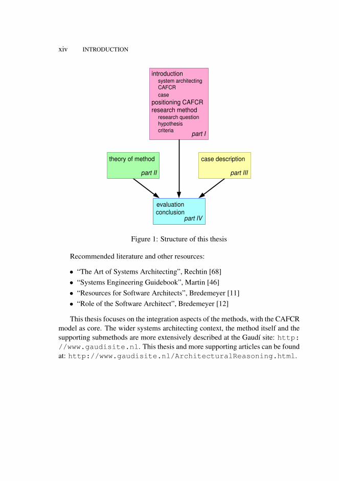
Figure 1 shows the structure of this thesis. Part I provides the context andgoal, provides a preview of the method, introduces the case positions the method,and describes the research method. The theoretical framework of the architect-ing method is described in part II. Part III describes the case: medical imagingworkstation. Part IV evaluates the architecting method and discusses the balancebetween the need for abstraction, resulting in genericity, and the need for details,requiring to be specific.
xiii
xiv INTRODUCTION
part I
introduction system architecting CAFCR case
positioning CAFCR research method
research question hypothesis criteria
part IV
evaluation conclusion
part II
theory of method
part III
case description
Figure 1: Structure of this thesis
Recommended literature and other resources:
• “The Art of Systems Architecting”, Rechtin [68]• “Systems Engineering Guidebook”, Martin [46]• “Resources for Software Architects”, Bredemeyer [11]• “Role of the Software Architect”, Bredemeyer [12]
This thesis focuses on the integration aspects of the methods, with the CAFCRmodel as core. The wider systems architecting context, the method itself and thesupporting submethods are more extensively described at the Gaudí site: http://www.gaudisite.nl. This thesis and more supporting articles can be foundat: http://www.gaudisite.nl/ArchitecturalReasoning.html.

Part I
Introduction to CAFCR andThreads of Reasoning
Chapters in Part I:
1. What is Systems Architecting in an Industrial Context?
2.Overview of CAFCR and Threads of Reasoning
3. Introduction to Medical Imaging Case Study
4. Positioning the CAFCR Method in the World
5. Research in Systems Architecting
6. Research Question and Hypothesis
1


Chapter 1
What is Systems Architecting inan Industrial Context?
1.1 Introduction
This thesis discusses the systems architecting of software and technology inten-sive products. Typical examples of software and technology intensive productsare televisions, DVD-players, MRI scanners, and printers. The creation of theseproducts is a multi-disciplinary effort by hundreds of engineers. The time betweenfirst product ideas and introduction into the market is in the order of a few monthsto a few years.
The concept architecture is borrowed from the building discipline. Architec-ture in building has a long history, with well known names as Vetruvius, Gaudí ,Lloyd Wright, Koolhaas, and many many more. System architecture can be com-pared with building architecture. The architecture of a building is for a large partthe experience that people get when they interact with the building, ranging from“how does it fit in the environment?”, “what impression does it make?”, “is it niceto be there?”, to “is it useful?”. In other words, the less tangible aspects of the per-ception of the building and the experience with the building are important aspectsof the architecture. The technical aspects of the structure and the construction ofthe building are also part of the architecture. The feasibility of an architecturalvision is enhanced or constrained by these technical aspects. The architecture isa dynamic entity that evolves during the life-cycle of the building. Every phasehas its own particular needs. Early-on the constructibility is important; later theusability and adaptability, and finally the disposability, become the points of at-
3
4 WHAT IS SYSTEMS ARCHITECTING IN AN INDUSTRIAL CONTEXT? 1.2
tention.In this book the system architecture is a close metaphor of the building archi-
tecture. The system architecture covers both the external aspects, often intangiblesuch as perception and experience, and the internal aspects, often more tangiblesuch as structure and construction. Note that this definition of architecture is ratherbroad, much broader for instance than usual in the software architecture commu-nity, see the Software Engineering Institute (SEI) inventory [37] for a much widervariation of definitions for architecture. Essential in this definition is the inclusionof the user context in architecture.
preceding architecture architecting architecture
PCP team architect, project leader,
engineers, product manager
problem knowledge
solution knowledge
business context
technology context
human context legend
stakeholders expectations, needs, concerns, constraints
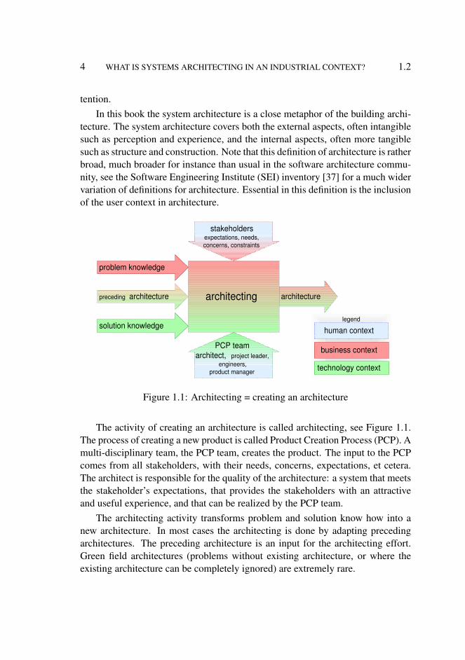
Figure 1.1: Architecting = creating an architecture
The activity of creating an architecture is called architecting, see Figure 1.1.The process of creating a new product is called Product Creation Process (PCP). Amulti-disciplinary team, the PCP team, creates the product. The input to the PCPcomes from all stakeholders, with their needs, concerns, expectations, et cetera.The architect is responsible for the quality of the architecture: a system that meetsthe stakeholder’s expectations, that provides the stakeholders with an attractiveand useful experience, and that can be realized by the PCP team.
The architecting activity transforms problem and solution know how into anew architecture. In most cases the architecting is done by adapting precedingarchitectures. The preceding architecture is an input for the architecting effort.Green field architectures (problems without existing architecture, or where theexisting architecture can be completely ignored) are extremely rare.

1.3 DESCRIPTION OF THE BUSINESS CONTEXT 5
1.2 Description of the Business Context
Architecting methods are positioned in the business context by means of a variantof the “BAPO”-model [58]. The business objectives of the company are the maininputs for architecting: generating market share, profit, ratio between sales andinvestments, et cetera. The specific business objectives depend strongly on thedomain: the type of product, customers, competition, application and market.
product creation
Business Architecting method
People
Process Organisation
sets targets
supports
supports
fits in
enables
perform
Figure 1.2: The business context of architecting methods
The business context is shown in Figure 1.2. The business will set targetsfor the architecting methods, the architecting methods will support the business.The product creation uses an architecting method to develop new products. Thearchitecting method must fit in the processes and the organization. People do thereal work, the method should help people to architect the desired system.
1.3 Internal Stakeholders
Many stakeholders in the business context are involved in the creation, produc-tion, sales and service of the products. All these operational stakeholders havetheir own concerns. These concerns translate into needs that influence the prod-uct specification. Figure 1.3 shows the internal stakeholders as annotation to fig-ure 1.2.
The policy and planning process sets the strategy and anticipates on the longerterm future. The scope of this process is at portfolio level. The policy and plan-ning process has the overview and strategic insight to allow decisions about prod-uct synergy and optimizations across products and product families. Also deci-sions about involving partners and the degree of outsourcing are taken here. Theseinternal strategic considerations also translate into operational requirements.
The customer-oriented process covers the entire order realization process aswell as the sales and life-cycle support (service) processes. Manufacturability,serviceability, and many more requirements are determined by these stakeholders.

6 WHAT IS SYSTEMS ARCHITECTING IN AN INDUSTRIAL CONTEXT? 1.4
product creation
Business Architecting method
People
Process Organisation
sets targets
supports
supports
fits in
enables
perform
policy and planning business, marketing, operational managers
product creation project leader, product manager, engineers,
suppliers
customer-oriented sales, service,
production, logistics
people, process, and technology
capability managers, technology suppliers
Figure 1.3: Stakeholders of the product creation within a company itself
All specification and design work is done in the product creation process.Many contacts with internal and external suppliers take place during product cre-ation. The operational needs of this process, such as work breakdown, test models,et cetera, also result in operational requirements.
The people, process, and technology management is concerned with processes,methods, tools, skills of people, intellectual property, and technology develop-ment. These concerns will sometimes result in operational requirements. Careshould be taken that the justification of these requirements is clear. From a busi-ness point of view these issues are means that must serve the business goals, notthe other way around.
1.4 Acknowledgements
Richard George attended me on the correct spelling of Lloyd Wright.
Chapter 2
Overview of CAFCR andThreads of Reasoning
2.1 Introduction
At the beginning of the creation of a new product the problem is often ill-definedand only some ideas exist about potential solutions. The architecting effort mustchange this situation in the course of the project into a well articulated and struc-tured understanding of both the problem and its potential solutions. Figure 2.1shows that basic methods and an architecting method enable this architecting ef-fort.
The basic methods are methods that are found in a wide range of disciplines,for example to analyze, to communicate, and to solve problems. These basicmethods are discussed in Chapter 7.
An overview of the architecting method is given in Section 2.2. The architect-ing method contains multiple elements: a framework, briefly introduced in Sec-tion 2.3, and submethods and integrating methods, which are described in part II.
2.2 Architecting Method Overview
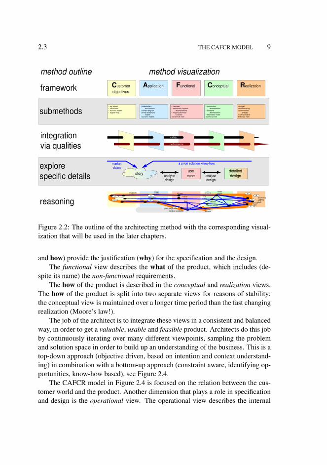
Figure 2.2 shows the overall outline of the architecting method. The right handside shows the visualization as it will be used in the later chapters. The frameworkis a decomposition into five views, the “CAFCR” model, see Section 2.3.
Per view in the decomposition a collection of submethods is given. The collec-tions of submethods are open-ended. The collection is filled by borrowing relevant
7

8 OVERVIEW OF CAFCR AND THREADS OF REASONING 2.3
architecture description: • articulated • structured problem and solution know-how architecting
vague notion of the problem
vague notion of potential solutions
basic methods
architecting method: • framework • submethods • integration methods
Spec
Des
ign
Rep
ort
Figure 2.1: An architecting method supports the architect in his process to go froma vague notion of the problem and a vague notion of the potential solutions to awell articulated and structured architecture description
methods from many disciplines.A decomposition in itself is not useful without the complementing integration.
Qualities are used as integrating elements. The decomposition into qualities isorthogonal to the “CAFCR” model.
The decomposition into CAFCR views and into qualities both tend to be ratherabstract, high level or generic. Therefore, a complementary approach is added toexplore specific details: story telling. Story telling is the starting point for specificcase analysis and design studies.
These approaches are combined into a thread of reasoning: valuable insightsin the different views in relation to each other. The basic working methods ofthe architect and the decompositions should help the architect to maintain theoverview and to prevent drowning in the tremendous amount of data and relation-ships. The stories and detailed case and design studies should help to keep theinsights factual.
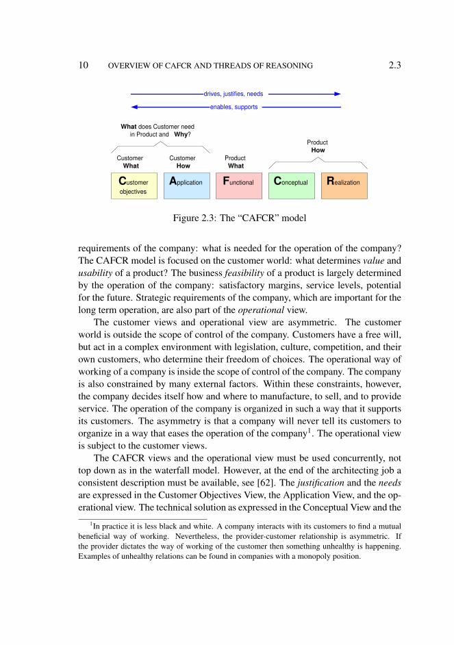
2.3 The CAFCR Model
The “CAFCR” model is a decomposition of an architecture description into fiveviews, as shown in Figure 2.3. The customer objectives view (what does the cus-tomer want to achieve) and the application view (how does the customer realizehis goals) capture the needs of the customer. The needs of the customer (what
2.3 THE CAFCR MODEL 9
explore specific details
submethods
framework
integration via qualities
reasoning
story use case analyse
design
detailed design analyse
design
a priori solution know-how market vision
safety
performance
+ key drivers + value chain + business models + supplier map
+ stakeholders and concerns
+ context diagram + entity relationship
models + dynamic models
+ use case + commercial, logistics
decompositions + mapping technical
functions and several more
+ construction decomposition
+ functional decomposition
+ information model and many more
+ budget + benchmarking + performance
analysis + safety analysis and many more
C ustomer objectives
A pplication F unctional C onceptual R ealization
method outline method visualization
throughput processing library
diagnostic quality
image quality IQ spec
pixel depth
CPU budget
typical case
common console
memory limit
BoM Moore's law
purchase price CoO
render engine
M'
S M
B
U"
P'
T
U
U' P
profit margin standard workstation
memory budget
Figure 2.2: The outline of the architecting method with the corresponding visual-ization that will be used in the later chapters.
and how) provide the justification (why) for the specification and the design.The functional view describes the what of the product, which includes (de-
spite its name) the non-functional requirements.The how of the product is described in the conceptual and realization views.
The how of the product is split into two separate views for reasons of stability:the conceptual view is maintained over a longer time period than the fast changingrealization (Moore’s law!).
The job of the architect is to integrate these views in a consistent and balancedway, in order to get a valuable, usable and feasible product. Architects do this jobby continuously iterating over many different viewpoints, sampling the problemand solution space in order to build up an understanding of the business. This is atop-down approach (objective driven, based on intention and context understand-ing) in combination with a bottom-up approach (constraint aware, identifying op-portunities, know-how based), see Figure 2.4.
The CAFCR model in Figure 2.4 is focused on the relation between the cus-tomer world and the product. Another dimension that plays a role in specificationand design is the operational view. The operational view describes the internal
10 OVERVIEW OF CAFCR AND THREADS OF REASONING 2.3
Customer What
Customer How
Product What
Product How
What does Customer need in Product and Why ?
drives, justifies, needs
enables, supports
C ustomer objectives
A pplication F unctional C onceptual R ealization
Figure 2.3: The “CAFCR” model
requirements of the company: what is needed for the operation of the company?The CAFCR model is focused on the customer world: what determines value andusability of a product? The business feasibility of a product is largely determinedby the operation of the company: satisfactory margins, service levels, potentialfor the future. Strategic requirements of the company, which are important for thelong term operation, are also part of the operational view.
The customer views and operational view are asymmetric. The customerworld is outside the scope of control of the company. Customers have a free will,but act in a complex environment with legislation, culture, competition, and theirown customers, who determine their freedom of choices. The operational way ofworking of a company is inside the scope of control of the company. The companyis also constrained by many external factors. Within these constraints, however,the company decides itself how and where to manufacture, to sell, and to provideservice. The operation of the company is organized in such a way that it supportsits customers. The asymmetry is that a company will never tell its customers toorganize in a way that eases the operation of the company1. The operational viewis subject to the customer views.
The CAFCR views and the operational view must be used concurrently, nottop down as in the waterfall model. However, at the end of the architecting job aconsistent description must be available, see [62]. The justification and the needsare expressed in the Customer Objectives View, the Application View, and the op-erational view. The technical solution as expressed in the Conceptual View and the
1In practice it is less black and white. A company interacts with its customers to find a mutualbeneficial way of working. Nevertheless, the provider-customer relationship is asymmetric. Ifthe provider dictates the way of working of the customer then something unhealthy is happening.Examples of unhealthy relations can be found in companies with a monopoly position.

2.3 THE CAFCR MODEL 11
C ustomer objectives
A pplication F unctional C onceptual R ealization
intention
constraint awareness
objective driven
context understanding
oppor- tunities
know how based
Customer What
Customer How
Product What
Product How
What does Customer need in Product and Why ?
Figure 2.4: Iteration over the CAFCR views and the operational view. The task ofthe architect is to integrate all these viewpoints, in order to get a valuable, usableand feasible product.
Realization View supports the customer to achieve his objectives and support thecompany in the operation. The Functional View is the interface between problemand solution world.
The CAFCR model will be used in this thesis as a framework for a next level ofsubmethods. Although the five views are presented here as sharp disjunct views,many subsequent models and methods don’t fit entirely into one single view. Thisin itself is not a problem; the model is a means to build up understanding, it is nota goal in itself.
The “CAFCR” model can be used recursively: many customers are part of alonger value chain and deliver products to customers themselves. Understandingof the customer’s customer improves the understanding of the requirements.
The notion of the customer is misleading. Many products have an extensiveset of stakeholders in the customer domain. One category of customer stake-holders are decision makers such as: CEO (Chief Executive Officer), CFO (ChiefFinancial Officer), CIO (Chief Information Officer), CMO (Chief Marketing Of-ficer) and CTO (Chief Technology Officer). Another category are people actuallyoperating the system, such as users, operators, and maintainers. A last categorymentioned here are the more remotely involved stakeholders, such as departmentchiefs and purchasers.

12 OVERVIEW OF CAFCR AND THREADS OF REASONING 2.3
Chapter 3
Introduction to Medical ImagingCase Study
3.1 Market and Application
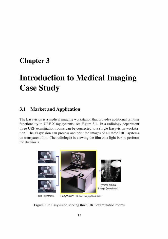
The Easyvision is a medical imaging workstation that provides additional printingfunctionality to URF X-ray systems, see Figure 3.1. In a radiology departmentthree URF examination rooms can be connected to a single Easyvision worksta-tion. The Easyvision can process and print the images of all three URF systemson transparent film. The radiologist is viewing the film on a light box to performthe diagnosis.
EasyVision: Medical Imaging Workstation URF-systems
typical clinical image (intestines)
Figure 3.1: Easyvision serving three URF examination rooms
13

14 INTRODUCTION TO MEDICAL IMAGING CASE STUDY 3.1
URF systems are used in gastrointestinal examinations. The patient has toconsume barium meal to enhance the contrast. Multiple exposures are made atdifferent locations in the intestines, while the barium meal progresses. The radi-ologist applies wedges to expose the area of interest and to minimize the X-raydose for the rest of the body.
Examination Room
Control Room
Reading Room
Corridor or closet
Examination Room
Control Room
printer
light box
detector
X ray source console
Figure 3.2: X-ray rooms with Easyvision applied as printserver
Around 1990 the normal production of transparent film was performed bymeans of a multi-format camera that makes screen copies of the CRT-monitor.The operator selects every image and sends it to the camera. A typical radiologydepartment layout is shown in Figure 3.2.
The introduction of the Easyvision made it possible to connect three exami-nation rooms via an Easyvision to a digital laserprinter. Figure 3.2 shows that theEasyvision can be positioned as a server in some cabinet, in which case the systemis used remotely, without any direct operator interaction. The Easyvision can alsobe placed in one of the control rooms, thereby enabling manual processing of theimages and manual formatting of the film.
The introduction of an Easyvision can immediately be justified by reducedfilm costs. Figure 3.3 shows a comparison of the conventional way of working,where images are screen copies of the CRT-monitor, and the films obtained bymeans of software formatting, where the film layout can be optimized to maximizethe number of images.
The conventional way of working results in many duplicates of the textualinformation around the image itself, because for each image the complete screenis copied. This is a waste of film space. On top of that all the textual informationis high contrast information, which is distracting while viewing for the diagnosis.

3.2 TECHNOLOGY 15
old: screen copy new: SW formatting
20 to 50% less film needed
Figure 3.3: Comparison screen copy versus optimized film
The digital availability of images opens all kinds of possibilities. The simplestis the separation of duplicate text information and images, which makes a muchhigher packing of images possible. Secondary possibilities are automatic shutterdetection and zoom-to-shutter.
3.2 Technology
product policy: standard HW SW "only"
40 MHz CPU 64 MByte memory 10 MBit/s ethernet 1 GByte disk
image quality image processing
print throughput
view response time
ca 1 film / minute film = 4k*5k pixels
subsecond retrieve screen = 1k*1k
tension
Figure 3.4: Challenges for product creation
The vision of the original designers of the product was that the technologicalinnovation in computer hardware is so fast that proprietary hardware developmentwould hamper future product innovation. A product policy was chosen to createproducts with the value in the software, using standard off-the-shelf hardware.This policy is potentially in conflict with the performance and image quality re-quirements. This challenge is shown and annotated in Figure 3.4.
Two types of performance are important in this product: throughput (theamount of film sheets printed per hour) and response time (the user interface re-

16 INTRODUCTION TO MEDICAL IMAGING CASE STUDY 3.2
SW
HW desk, cabinet
laser printer laser printer
workstation optical disc
laser printer
operating system
application application
framework, libraries
remote control
make
buy network
legend
to ols
Figure 3.5: Top-level decomposition
sponse time should be subsecond for image retrieval). This performance must beachieved with a minimal guarantee in image quality. For instance, pixel replica-tion for still images on screen is not acceptable, while bi-cubic interpolation isrequired for the high resolution of the film images. These requirements must berealized with the workstation in the 5 to 10 k$ range of that time, which corre-sponds with a 40 MHz CPU and a maximum amount of memory of 64 MByte.The examination rooms are connected to the system via 10 Mbit ethernet, whichwas state of the art in 1990.
Figure 3.5 shows the top-level decomposition of the system. Most hardwareis off-the-shelf. A custom remote control was added to obtain a very direct andintuitive user interface. In order to fit the system in the hospital environment, thepackaging of the system was also customized. The packaging part of the systemwas decoupled from the hardware innovation rate by a box in a box concept: theoff-the-shelf computer box was mounted in a larger deskside-cabinet.
The software is based on a standard operating system (Unix), but the libraries,framework and applications are tailor-made. The framework and libraries containa lot of clinical added value, but the end user value is in the applications.
The designers of Easyvision introduced many technological innovations in arelatively conservative product creation environment. The following list showsthe technological innovations introduced in the Easyvision:
• standard UNIX-based workstation• full SW implementation, more flexible• object-oriented design and implementation (Objective-C)• graphical User Interface, with windows, mouse et cetera• call back scheduling, fine-grained notification

3.2 TECHNOLOGY 17
• data base engine: fast, reliable and robust• extensive set of toolboxes• property-based configuration• multiple coordinate spaces
The introduction of these innovations enabled the later successful expansion intoa family of products, with many application innovations. In Part III we willshow some of these innovations in more detail and in relation to the productvalue.

18 INTRODUCTION TO MEDICAL IMAGING CASE STUDY 3.2
Chapter 4
Positioning the CAFCR Methodin the World
4.1 Introduction
This chapter positions the “architectural reasoning” architecting method relativeto other engineering and architecting methods.
Section 4.2 describes work that is related to the research of architecting meth-ods. Section 4.3 articulates explicitly the specific contribution of this thesis. TheIEEE 1471 is explained further in section 4.4, because its contents is highly rele-vant in this context.
4.2 Related Work
Conventional disciplines, such as mechanical engineering, electronic engineering,et cetera have a clear set of methods and tools. Students can learn the disciplineby attending universities and following their curriculums.
This is not the case for systems architecting. Only a few universities teachsystems architecting. There are multiple reasons for the fact that teaching systemsarchitecting methods at universities is difficult. First of all, sufficient depth ofengineering know-how is needed to be able to work in the architecting area. Inother words, a conventional discipline is a prerequisite to become an architect.
Secondly, architecting is done for problems with a wider scope than conven-tional engineering problems. The larger the scope, the more ill-defined a problem
19

20 POSITIONING THE CAFCR METHOD IN THE WORLD 4.2
very generic methods
methods also addressing process
and organization
multi-disciplinary systems architecting
methods software architecting
methods
CAFCR and threads of reasoning
SE practices SAAM ATAM
1471 GST (General System Theory)
TRIZ SEI INCOSE
IEEE
Altshuller
Systems architecting
Rechtin Maier
Martin
9126 ISO
Hitchins Heylighen
Systems engineering
ZIFA Zachman
VAP Bredemeyer
mono-disciplinary engineering methods
4+1 Kruchten
4 views Soni
Figure 4.1: Classification of architecting methods
becomes. The methods range from flexible for ill-defined problems to rigid forwell-defined problems1.
Figure 4.1 shows a classification of architecting methods, with the scope ofthe method as differentiating factor. The software architecting methods have thesmallest scope. System architecting methods widen the scope to system level.This thesis addresses the multi-disciplinary systems architecting methods. Thescope can be further increased to include processes and organizational issues. Thewidest scope pertains to very generic methods, which claim to be domain agnosticand to create value by cross-fertilization across domains. At the bottom of theclassification we find the mono-disciplinary methods, which are the fundamentalson which all methods build.
4.2.1 Software Architecting Methods
A whole class of methods originate in the Information Technology (IT) world andaddress software architecting. The software architecting methods do not addressthe system level problems, such as hardware/software trade-offs.
The Software Engineering Institute at Carnegie Mellon University, [71] and [72],increases the problem scope and puts a lot of emphasis on processes, and restrictsitself to software architecture. Examples of methods developed here are Software
1Of course this is an oversimplification. Sometimes agile methods are highly effective in well-defined problems. Sometimes rigid methods can perform wonders in an ill-defined problem. Ingeneral, mature methods are available for well-defined problems, while the uncertainty in ill-definedmethods requires more flexibility.

4.2 RELATED WORK 21
Architecture Analysis Method (SAAM) [41] and Architecture Trade Off AnalysisMethod (ATAM) [40].
Zachman provides a framework for enterprise architectures, see [80]. Thisframework defines two dimensions with six aspects each, creating a space with 36different views. Bredemeyer describes a nice visual method “The Visual Archi-tecting Process” [13]. The Bredemeyer method provides context views and a pathfrom context views to design views. Both Zachman and Bredemeyer are softwareoriented.
Well known multi-view software architecting methods are Soni [33], and the4+1 method from Kruchten [43]. These two methods use multiple views. Thescope of Soni methods, however, is completely limited to the technical solutiondomain. Kruchten is also focused on the technical solution domain, but he makesa small step into the problem domain by use cases in the fifth view.
ISO 9126 [38] is a standard that consolidates a quality framework. The frame-work addresses the same type of qualities that are discussed in chapter 10. Unfor-tunately ISO 9126 limits itself to software only.
4.2.2 Multi-disciplinary System Architecting Methods
A further increase in scope can be found in the Systems Engineering Community,with INCOSE[36] (International Council on Systems Engineering) as representa-tive organization. All stakeholders are taken into account and the full life-cycleis emphasized. Examples of this approach can be found at the INCOSE website [21].
Some standardization work has been done in the scope of systems, stakehold-ers and the full life cycle. An example is IEEE 1471, which is a framework thatfits into this scope, see section 4.4.
This thesis about architectural reasoning, based on the “CAFCR” method,also addresses the scope of systems, their stakeholders, and the full life-cycle.Boundary conditions to the methods in this thesis are structure and characteristicsof the business, the organizations, and the processes.
4.2.3 Methods also Addressing Process and Organization
The architect is often confronted with many more needs, worries, and complica-tions, originating from human and business aspects. This broad working environ-ment is full of uncertainties. Rechtin and Maier [68] address this wider scope fromthe architecting point of view. Martin [46] comes from the systems engineering

22 POSITIONING THE CAFCR METHOD IN THE WORLD 4.3
community. He provides a method that deals with all the complexity, but that hasless emphasis on the human aspects.
4.2.4 Very Generic Methods
Many system architecting and design methods are universally applicable. GeneralSystems Theory (GST), for example, addresses any kind of system, ranging fromeconomical, or ecological, to social, see for instance [31] and [32]. GST suffersfrom being extremely abstract and difficult to apply, due to a broad scope and thegeneric nature of the theory.
TRIZ [1] is a methodology for innovation that originates in Russia. A setof innovation patterns is derived from studying large collections of inventions.These patterns are transformed into innovation methods that can be applied to avery broad range of applications. One of the starting points of TRIZ is that the wayof innovating in one domain provides inspiration for innovation in other domains.TRIZ provides a number of useful insights.
The subtitle of this thesis, balancing genericity and specificity, indicates oneof the continuous struggles of the architect: the power and the beauty of genericsolutions versus the uniqueness of effective, individual solutions. Or in otherwords, do we get carried away in generic thinking, or do we drown in the details?In this thesis the scope will be limited to systems with embedded processors andsoftware. This still pertains to a very broad range of products: from wafersteppersto televisions, and to systems on a chip).
4.3 What is the Unique Contribution of this Work?
This section discusses the unique contributions of the CAFCR method. Althoughevery single element mentioned here is present in one of the discussed methods,the uniqueness of CAFCR is the combined application of all these elements si-multaneously.
Integral and Multi-disciplinary This work focuses on architecting methods onthe system level for embedded systems. As described in Subsection 4.2.1,many methods focus only on a part of the multi-disciplinary system prob-lem, for instance only on the software architecture. A lot of architectingmethods provide more or less closed and complete solutions. The availablemethods are partial methods from a systems viewpoint. The method de-scribed in this thesis addresses the integration of results obtained with these

4.3 WHAT IS THE UNIQUE CONTRIBUTION OF THIS WORK? 23
more partial methods. Also a number of multi-disciplinary system designsubmethods are described in this thesis. The basis for this integration is thecombined use of CAFCR views, qualities, and threads of reasoning.
Goal-Oriented This method stresses the importance of being externally oriented.Architecting must be goal-oriented or objective-driven. Many existing meth-ods do not take the goals and objectives into account.
Practical, based on Industrial Experience The method, which is based on a broadindustrial experience, addresses the real problems2 in system design. Theusability aspect can be seen in the light-weight use of formulas, and in theassociation of many statements with common sense. Some of the publishedmethods are more academic, well thought through, but not really addressingthe problems in system design, and difficult to implement in the industrialpractice.
Flexible The wide application range of the creation of software and technologyintensive products, requires a flexible and adaptive method. The methodmust provide guidance, and should not constrain the architect by forcing arigid harness on him. In principal the architecting method must be able tointegrate the results of any partial method.
Builds on standards The method builds on top of standards, such as ISO 9126for qualities and IEEE 1471. In fact the method can be viewed as an instan-tiation of an IEEE 1471 method, see Section 4.4.
Support for short innovation cycles System engineering methods originate fromthe aerospace domain, with very different reliability and safety require-ments. Such methods tend to be more rigid, resulting in very long devel-opment cycles. This distinction of “slow but safe” domains versus “fast butless reliable” domains disappears quickly. Cross-fertilization of these do-mains can be very useful. In contrast to the aerospace domain the CAFCRmethod is intended for domains with short innovation cycles.
2Many problems in system design are caused by unforeseen interactions between independentdesigned functions or qualities. See for instance Chapter 13 for examples of system design problemsin the Medical Imaging case.
24 POSITIONING THE CAFCR METHOD IN THE WORLD 4.4
4.4 IEEE 1471
System Architecture has
Architecture Description
Des
crib
ed
by
Stakeholder view
viewpoint
concern covers conforms to
covers
model
defines
Consists of
1 1
has
Figure 4.2: The IEEE 1471 model for stakeholders, viewpoints and architecturedescriptions
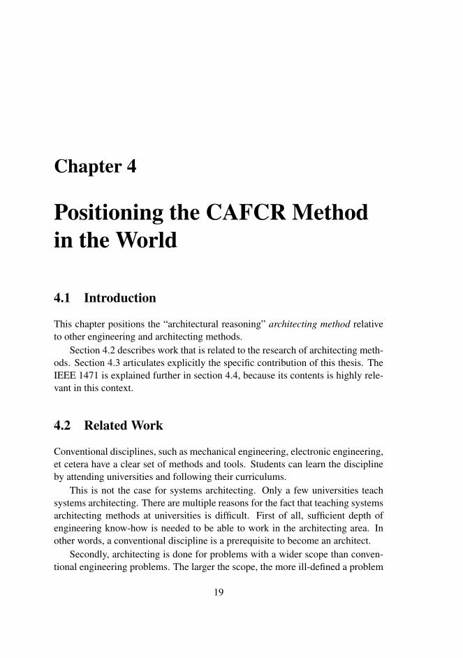
Figure 4.2 shows a somewhat simplified IEEE 1471 model. IEEE 1471 [6] isa standard that describes a framework for architecting. The framework introducesa number of important concepts:
Stakeholders People or organizations that have an interest in the system underconsideration.
Concerns The articulation of the needs and worries of the stakeholders.
Viewpoints The points of view used to describe part of the problem or solution.IEEE 1471 makes a subtle difference between view and viewpoint. We ig-nore this difference here.
Models Frequently used method to make problem and solution descriptions.
Architecture description The combination of stakeholders, concerns, viewpointsand models to describe the architecture of a system.
The main contribution of IEEE 1471 is to provide a framework that covers allof these aspects. The individual concepts have been in use by many architects fora long time.
On top of providing the framework, IEEE 1471 also recognizes the fact thatcomplete consistency in the entire architectural description is an illusion. The

4.4 IEEE 1471 25
real world of designing complex systems is full of stakeholders with fuzzy needs,often contradictory in itself and conflicting with needs of other stakeholders. Theinsights of individual designers are also full of different and changing insights.This notion of incomplete consistency is not an excuse for sloppy design; quitethe opposite: recognizing the existence of inconsistencies is a much better startingpoint for dealing with them. In the end, no important inconsistencies may be leftin the architecture description.
Architecture
Subset of which architect is aware
Architecture description
Actually written by architect(s)
Flattened into
Figure 4.3: The architecture description is by definition a flattened and poor rep-resentation of an actual architecture.
IEEE 1471 makes another interesting step: it discusses the architecture de-scription not the architecture itself. The architecture is used here for the way thesystem is experienced and perceived by the stakeholders3.
This separation of architecture and architecture description provides an inter-esting insight. The architecture is infinite, rich and intangible, denoted by a cloudin figure 4.3. The architecture description, on the other hand, is the projection,and the extraction of this rich architecture into a flattened, poor, but tangible de-scription. Such a description is highly useful to communicate, discuss, decide,verify, et cetera. We should, however, always keep in mind that the description isonly a poor approximation of the architecture itself.
3Long philosophical discussions can be held about the definition of the architecture. Thesediscussions tend to be more entertaining than effective. Many definitions and discussions about thedefinition can be found, for instance in [32], [10], or [37]

26 POSITIONING THE CAFCR METHOD IN THE WORLD 4.4

Chapter 5
Research in Systems Architecting
5.1 Introduction
Architecting is an extremely broad subject, taking into account many ill-definedneeds, concerns, expectations, et cetera. Architecting methods are the result ofconsolidation of experience of architects. Architecting methods should help ar-chitects to architect. Research of architecting methods is again one step moreabstract: it is the study and exploration of architecting methods in a systematicway.
method method system
system context
users customers
designers manufacturer
suppliers
managers
architect
architecting architecting
thought processes
method research
report
method research
legend
specific tangible
ill defined intangible
Figure 5.1: Research of architecting methods in the context of system design
Section 5.2 describes a technology management model. The technology man-agement model is used in Section 5.4 to describe the research method used inthis thesis to investigate an architecting method. Section 5.3 discusses the chal-
27
28 RESEARCH IN SYSTEMS ARCHITECTING 5.2
lenges of doing research of architecting methods in a scientific way. Section 5.5describes how the distance between industrial practice and scientific research canbe bridged. Section 5.6 describes the environment where the research takes place.
5.2 Technology Management Cycle
The creation of software and technology intensive products requires by definitionquite some technology know-how. These technologies can be classified as hardand soft:
• Hard technology is the tangible engineering and scientific know-how, suchas software and electronics engineering, and mathematics, physics, chem-istry, and biology. The know-how from these sciences is very objective anduniversally applicable (the elasticity in the USA is the same as the elasticityin China). The performance of the product is determined by the right choiceof hard technologies.
• Soft technology is the less tangible know-how of how to create a productwith a team of people. Soft technologies are based on a mixture of sciencesand human arts. The know-how of soft technologies is more subjective,the human factors are less well reproducible (a method working well in theUSA might fail in China and vice versa). The performance of the productcreation team depends on the right application of soft technologies.
The intensive use of technology in these products requires explicit manage-ment of the technology: technology management. Architecting methods are man-aged as part of the (soft) technology.
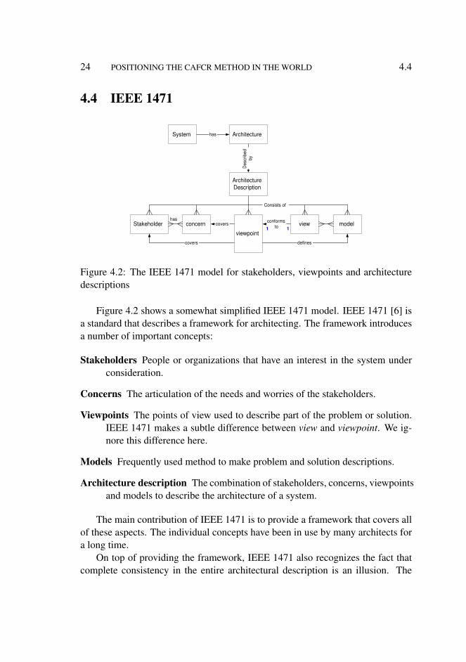
Technology management can be modeled as a cyclic process [17], as shownin Figure 5.2. Most of the time is spent in the application of technology, in otherwords in the creation of new systems. After applying the technology it is rec-ommended to learn from this application by reflection. The learning experiencecan be made (partially) accessible to others by consolidating the know-how, forinstance in documentation.
At the end of the consolidation insight will exist in strengths and weaknessesof the technology, both in the hard technology choices as well as in the soft tech-nology (the approach taken). It is recommended to take this know-how as a start-ing point for an exploration phase.
The exploration phase should be used to refresh the designers and architects,and to open new opportunities in technology. This requires that they know the

5.3 CHALLENGES TO DO RESEARCH IN A SCIENTIFIC WAY 29
Application of technology
Consolidation of know how
Exploration of new ideas
Literature search Creative option generation Try out
Industry as laboratory
Reflection Write articles Create courses
Figure 5.2: Technology Management Cycle
state of the art in the world, by reading literature, visiting conferences, et cetera.New technology options can be added by means of creative brainstorms . Promis-ing technology must be explored hands-on.
In the next application phase a limited set of new technologies is applied inpractice.
This thesis focuses entirely on an architecting method. The architect and thearchitecture are heavily involved with a lot of hard technology. However, themanagement of hard technologies and soft technologies other than architectingmethods is outside the scope of this thesis.
5.3 Challenges to do Research in a Scientific Way
Science is applied in a wide range of areas, from proof-based mathematics todescriptive reasoning in human sciences, see Figure 5.3.
The level of certainty of the results decreases when moving from hard sciencesto soft sciences. Mathematical proofs provide certainty1, see also [35]. Physicsprovides a confidence level that increases by validating predicted outcomes, or itapplies a falsification process as described by Popper [76].
Medical sciences need a lot more trial and error, where evidence is built up
1As far as the proof is verifiable and the verifiers can be trusted. The absolute certainty is herealso decreased by the human factor: the proof is as certain as the quality of the provider of the proofand the verifiers of the proof. Automation shifts the problem to the tool, which also in some wayoriginates in fallible human beings.

30 RESEARCH IN SYSTEMS ARCHITECTING 5.3
hard soft
mathematics physics medicine human sciences
prove prediction statistics descriptive reasoning
charlatan
handwaving
architecting methods
example: security
crypto biometric identification human factor
certainty confidence evidence based
plausible convincing
no science
soft science
hard science
legend
Figure 5.3: Spectrum of sciences
in extensive statistical studies. The evidence is hampered by many factors thatinfluence the outcome of the medical study, but that are outside the control of theexperimenter. Worse is that many of the factors are unknown to the experimenterand his peers. Cause and result are often more ambiguous than people realize.Despite all these disclaimers the medical sciences have created a large body ofknowledge.
The human sciences (psychology, sociology, pedagogy, et cetera) have alreadya tremendous challenge in making statements plausible. Human behavior showsa wide variation, depending on many factors, such as culture, age, gender, andstatus. Individual human behavior is often poorly predictable. Case descriptionsare used in a heuristic approach. The step from case descriptions to a workablehypothesis needs a lot of interpretation. Adding more case descriptions will helpin making the issue more plausible, but hard evidence is nearly impossible. Amore experimental approach with small scale experiments is possible, but theseexperiments are often highly artificial.
The scientific community dislikes the charlatans, who can be very convincingby hand-waving arguments, but in fact are selling hot air.
Architecting integrates all of these different types of sciences, from mathe-matical to human sciences. For instance in security design cryptographic proofis important, and also biometrics authentication. However a security solution thatdoes not take the human behavior into account fails even before it is implemented.
Research of architecting methods is inherently the combination of hard facts
5.3 CHALLENGES TO DO RESEARCH IN A SCIENTIFIC WAY 31
in an environment full of soft factors. Most of present-day hard disciplines (math-ematics, physics, electronics, mechanics, et cetera) are frightened away by the softfactors. Most of the soft disciplines (psychology, philosophy, business manage-ment) have no affinity with the complexity in the hard facts. The challenge in thesystems discipline is to tackle the soft factors, with sufficient understanding of thehard side.
make explicit
substantiate
try to validate
research question hypothesis
heuristics principles
facts analysis
evaluate open debate
body of knowledge cases
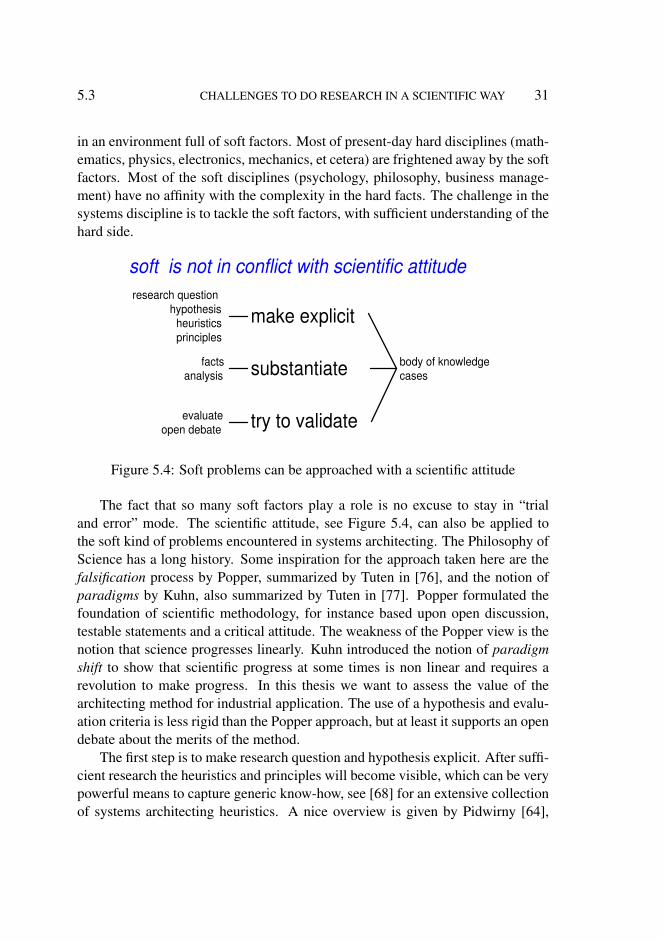
soft is not in conflict with scientific attitude
Figure 5.4: Soft problems can be approached with a scientific attitude
The fact that so many soft factors play a role is no excuse to stay in “trialand error” mode. The scientific attitude, see Figure 5.4, can also be applied tothe soft kind of problems encountered in systems architecting. The Philosophy ofScience has a long history. Some inspiration for the approach taken here are thefalsification process by Popper, summarized by Tuten in [76], and the notion ofparadigms by Kuhn, also summarized by Tuten in [77]. Popper formulated thefoundation of scientific methodology, for instance based upon open discussion,testable statements and a critical attitude. The weakness of the Popper view is thenotion that science progresses linearly. Kuhn introduced the notion of paradigmshift to show that scientific progress at some times is non linear and requires arevolution to make progress. In this thesis we want to assess the value of thearchitecting method for industrial application. The use of a hypothesis and evalu-ation criteria is less rigid than the Popper approach, but at least it supports an opendebate about the merits of the method.
The first step is to make research question and hypothesis explicit. After suffi-cient research the heuristics and principles will become visible, which can be verypowerful means to capture generic know-how, see [68] for an extensive collectionof systems architecting heuristics. A nice overview is given by Pidwirny [64],

32 RESEARCH IN SYSTEMS ARCHITECTING 5.3
using characteristics such as neutral and unbiased.The next step is to substantiate the benefits of proposed methods with facts and
analysis. The last step is to strive for validation. For many soft issues validationwill be an unreachable ideal. Increasing the plausibility is then the maximum thatcan be achieved.
These steps together contribute to the building of a body of know-how (as allsciences do), of which a significant part will be based on case descriptions.
creative
systematic
repeated creative
systematic
creative
systematic
more performance
and functionality causes more complexity and requires more effort
active work on
systematic methods reduces effort and
the need for a lot of
creative effort
systematic methods
new creative
year X year X+4 year X+4
Figure 5.5: A scientific base is required to cope with the growing system effort.The scientific base provides a systematic approach that helps to solve known typesof problems with less, more systematic, effort.
The relevance for the product creation companies is that the increasing ef-fort of creating more powerful, but complex systems, is kept manageable. Theratio between the amount of systematic work, engineering, and the amount of cre-ative/chaotic work should preferable stay the same. Due to the increasing com-plexity, in both hard and soft issues, this ratio will worsen if we are not able tomake part of the system work more systematic.
Figure 5.5 shows the amount of systematic work and creative work. In theelectronics industry the effort to create new circuits increases exponentially, moreor less following Moore’s Law. The phenomenon that the product needs and pos-sibilities increase faster than our design know-how is known as the productivitygap, see for example [42]. The first bar shows the amount of systematic work atthe bottom and the creative work at the top. The new development shown in the

5.4 ARCHITECTING RESEARCH METHOD 33
second bar, taking place several years later, in this example four years, requiresabout twice the amount of work. If we do not develop the system discipline a lotof the future system work will still be done in “trial and error” mode, representedby the repeated creative work. The new functionality, performance and complex-ity challenges also require new creative work. If the creative work of the pastcan be captured in more systematic approaches then the repeated creative work istransformed in less systematic work, as shown in the third bar.
One of the symptoms for this trend of increasing creative work is the relativeincrease of the integration period and integration effort. The lack of a systematicapproach in the early design phases is solved by applying a lot of creativity insolving the problems during integration. This effect is visible in complex systems,such as MRI scanners, wafersteppers, and video processing platforms.
The message behind this figure is that product creation will always have acreative component. Providing a scientific base will never remove the need forhuman creativity. A scientific base will enable the effective use of the creativetalent, not wasting it on problems that could have been solved in a systematicway.
Figure 5.5 suggests an incremental increase of creation effort. Many products,such as cardiovascular X-ray systems, wafersteppers, and televisions show suchexponential growth of the effort. When developing system architecting methodsthe ambition should be to develop also the development of system design andimplementation methods that decrease the desired effort. Once the know-how iscaptured in methods a next step in support can be made by further automation andsupporting tools. Systematizing know how precedes automation and tooling.
5.4 Architecting Research Method
This thesis is based on research by means of the conventional hypothesis (seeSection 6.3) and evaluation method, complemented by case descriptions (Part III).The research starts with a research question, described in Section 6.2 that aftersome exploration work is used to formulate a hypothesis. The hypothesis is nextassessed to be valid or invalid by means of criteria, see Section 6.4.
The research method and the architecting methods are very abstract entities.These methods are illustrated by case descriptions. Specific case descriptionsmake it possible to capture the experience of the otherwise rather generic methods.The case descriptions describe parts of actual system architectures.
In the human sciences case descriptions are one of the major research meth-

34 RESEARCH IN SYSTEMS ARCHITECTING 5.5
ods [70]. Theory in these sciences define many abstract concepts that are difficultto make precise. Case descriptions support the definition of the concepts. Atthe same time, they complement the abstract concept definitions, by being veryspecific, thereby helping to clarify and to educate.
5.5 Distance between Industrial Practice and ScientificResearch
The main challenge in the research of architecting methods is to bridge the dis-tance between the pragmatic world of product creation in the industrial contextand the scientifically sound research of architecting methods. Figure 5.6 showsthe distance between the practitioners and the scientific foundation as an abstrac-tion hierarchy.
Application of technology
Consolidation of know how
Exploration of new ideas
archi- tecting method
meta 0
bottom line: product
creation
meta 1
enabling: architecting
method
meta 2
pro-active: research of
architecting method
meta 3
scientific foundation: method to research
architecting methods
architecting method research
research method
Figure 5.6: Moving in the meta direction. Research of architecting methods is twosteps of indirection away from the bottom line of product creation. The scientificfoundation for this work is another indirection step
The status quo in systems architecting is that most architects learn by trialand error2. These architects are directly working in the product creation process,
2 A systematic foundation for systems architecting is lacking in the companies I have worked for.Most companies do have extensive process handbooks and quality assurance handbooks, coveringdocumentation, verification, project management, and many more issues. However, the multidisci-
5.6 RESEARCH ENVIRONMENT 35
where the bottom line is to create successful products.The approach taken in architecting can be abstracted into an architecting
method; this is the first step in the meta-direction. Doing systematic researchof architecting methods is a second step in the meta-direction. The definition ofa research method (to investigate architecting methods) provides the systematicresearch with a scientific foundation: the third step in the meta-direction. Thesethree levels of abstractions illustrate the different worlds of practitioners and re-searchers.
The drive behind this thesis is the assumption that building a scientificallyfounded body of knowledge will improve product creation effectiveness directlyor indirectly. An example of indirect improvement by means of rational designmethods is described by Parnas and Clements in “A Rational Design Process: Howand Why to Fake It” [62]. The rational design process is in the industrial practiceused indirectly in the later phases of the product creation for documentation andcommunication.
5.6 Research Environment
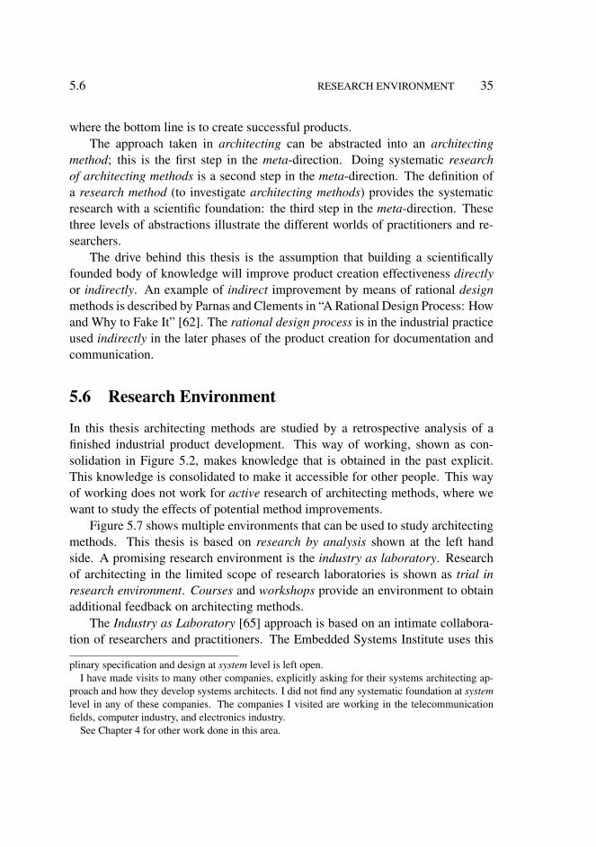
In this thesis architecting methods are studied by a retrospective analysis of afinished industrial product development. This way of working, shown as con-solidation in Figure 5.2, makes knowledge that is obtained in the past explicit.This knowledge is consolidated to make it accessible for other people. This wayof working does not work for active research of architecting methods, where wewant to study the effects of potential method improvements.
Figure 5.7 shows multiple environments that can be used to study architectingmethods. This thesis is based on research by analysis shown at the left handside. A promising research environment is the industry as laboratory. Researchof architecting in the limited scope of research laboratories is shown as trial inresearch environment. Courses and workshops provide an environment to obtainadditional feedback on architecting methods.
The Industry as Laboratory [65] approach is based on an intimate collabora-tion of researchers and practitioners. The Embedded Systems Institute uses this
plinary specification and design at system level is left open.I have made visits to many other companies, explicitly asking for their systems architecting ap-
proach and how they develop systems architects. I did not find any systematic foundation at systemlevel in any of these companies. The companies I visited are working in the telecommunicationfields, computer industry, and electronics industry.
See Chapter 4 for other work done in this area.

36 RESEARCH IN SYSTEMS ARCHITECTING 5.6
large industrial project
>100 man
architecting research by
analysis
large industrial project
>100 man
course setting
small research project
<10 man
method trial large industrial
project >100 man
method trial
active architecting
research
industry as laboratory
active architecting
research
trial in research environment
large industrial projects
>100 man
method trial
architecting research feedback
feedback from courses
workshop setting
method as framework
architecting research feedback
feedback from workshop
method
retrospective analysis
Figure 5.7: Obtaining practical case data of architecting methods from multiplesources
model as the basis for research [69]. The industrial environment is used to try outarchitecting methods. In the industrial environment the typical time and resourcepressures, and the larger size (one or two orders of magnitude larger than in typicalresearch projects) are inherently realistic for the industrial context.
Some architecting methods are also explored in research projects. For in-stance, story telling, as described in Chapter 11, is used in ambient intelligenceprojects. The CAFCR model has been used many times in research workshops asa framework. Project reviews and workshop evaluations provide feedback on thearchitecting method for this research project environment.
Partial architecting methods (for instance story telling again) are also used incourse settings, where they are applied to many different systems, ranging fromsilicon chips to Cardiovascular X-ray systems. More than 300 designers and archi-tects have participated in Systems Architecting courses, using partial methods fortens of different systems. This provides valuable feedback of these methods whenapplied to real systems. See [51] for the course program. The entire course ma-terial, including exercises, can be found at: http://www.gaudisite.nl/SARCH.html.
The CAFCR method is also used within Philips as a framework for performingarchitecture workshops. External and internal project stakeholders present duringthe workshops use (parts of) the CAFCR method as a means to structure theirworkshop. The evaluation at the end of a workshop provides feedback for thearchitecting method. In Chapter 19 the evaluations from many workshops arediscussed.
Chapter 6
Research Question andHypothesis
6.1 Introduction
The starting point for the investigation of architecting methods in this thesis isthe research question, articulated in Section 6.2. An hypothesis is formulated inSection 6.3. The criteria to validate the hypothesis are defined in Section 6.4.Section 6.5 summarizes all three aspects in a single overview, and shows how thedifferent parts of the thesis fit together in this thesis.
6.2 Research Question
Figure 6.1 shows the annotated research question. The core research question iswhat architecting methods enable the creation of successful products. This corequestion is more focused by adding a more specific environment: a dynamic mar-ket and a heterogeneous industrial context. The product category is also narroweddown by looking only at technology and software intensive products.
Successful products are products that satisfy the customers and result in athriving business. In present-day economy this means that time plays a dominantrole, products must be in time. The economic reality and the hefty competitionforce economic constraints on the created product and its timing. This economicreality requires pragmatism in the architecting methods. Many academic meth-ods, however, suffer from a mismatch with these economic and time constraints.For instance formal verification systems work well for small well-defined prob-
37
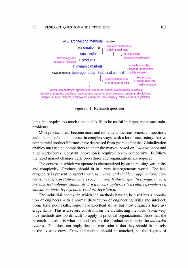
38 RESEARCH QUESTION AND HYPOTHESIS 6.2
What architecting methods enable
the creation of
successful
products
in dynamic markets
developed in a heterogeneous industrial context
satisfied customers thriving business
some poor, some excellent, mostly average
technology and software intensive
in time within economic constraints
uncertainty rules need for innovation agility required
normal distribution of engineering skills
views, stakeholders, applications, concerns, needs, expectations, interests, functions, features, qualities, requirements, systems, technologies, standards, disciplines, suppliers, sites, cultures, employees, education, tools, legacy, other vendors, legislation
Figure 6.1: Research question
lems, but require too much time and skills to be useful in larger, more uncertain,problems.
Most product areas become more and more dynamic: customers, competitors,and other stakeholders interact in complex ways, with a lot of uncertainty. Activecommercial product lifetimes have decreased from years to months. Globalizationenables unexpected competitors to enter the market, based on low-cost labor andhuge work-forces. Constant innovation is required to stay competitive. To followthe rapid market changes agile procedures and organizations are required.
The context in which we operate is characterized by an increasing variabilityand complexity. Products should fit in a very heterogeneous world. The het-erogeneity is present in aspects such as: views, stakeholders, applications, con-cerns, needs, expectations, interests, functions, features, qualities, requirements,systems, technologies, standards, disciplines, suppliers, sites, cultures, employees,education, tools, legacy, other vendors, legislation.
The industrial context in which the methods have to be used has a popula-tion of engineers with a normal distribution of engineering skills and intellect.Some have poor skills, some have excellent skills, but most engineers have av-erage skills. This is a severe constraint on the architecting methods. Some verynice methods are too difficult to apply in practical organizations. Note that theresearch question is what methods enable the product creation in the industrialcontext. This does not imply that the constraint is that they should fit entirelyin the existing crew. Crew and method should be matched, but the degrees of

6.3 HYPOTHESIS 39
freedom in composing a PCP team in an industrial context are quite limited.
6.3 Hypothesis
The variability of products being created is so large, that one all encompassingmethod is impossible. The dynamic range in requirements spans many ordersof magnitude. For example requirements for power consumption, weight, andprocessing needs differ a factor of 1000 for products such as televisions and GSMcellphones. It is more feasible to grow a rich collection of submethods than todevelop a single all encompassing method. Submethods are methods that addressa smaller part of the problem. This step moves the problem to another area: howto combine multiple submethods in a useful way?
A rich collection of submethods fitting in a multi-view framework
complemented with reasoning methods enables successful architecting of
technology and software intensive complex systems in heterogeneous environments
by means of generic insights grounded in specific facts
Figure 6.2: Hypothesis
The hypothesis, as shown in Figure 6.2 formulates the need for a multi-viewframework. The submethods must fit in the multi-view framework. Reasoningmethods are needed to cope with multiple submethods.
The claim is that this combination of a rich collection of submethods, multi-view framework, and reasoning methods enables the successful architecting oftechnology and software intensive complex systems in heterogeneous environ-ments.
The generic term product in the research question is replaced by the morefocused notion of technology and software intensive systems. The research de-scribed in this thesis has been limited to embedded systems. Embedded systemsare systems with embedded computing hardware and software that have interac-tion with the physical world. This interaction with the physical world is technol-ogy intensive, for example actuator technology and sensor technology.
In addition two crucial characteristics of architecting work are added to theclaim: the use of generic insights grounded in specific facts. These two character-
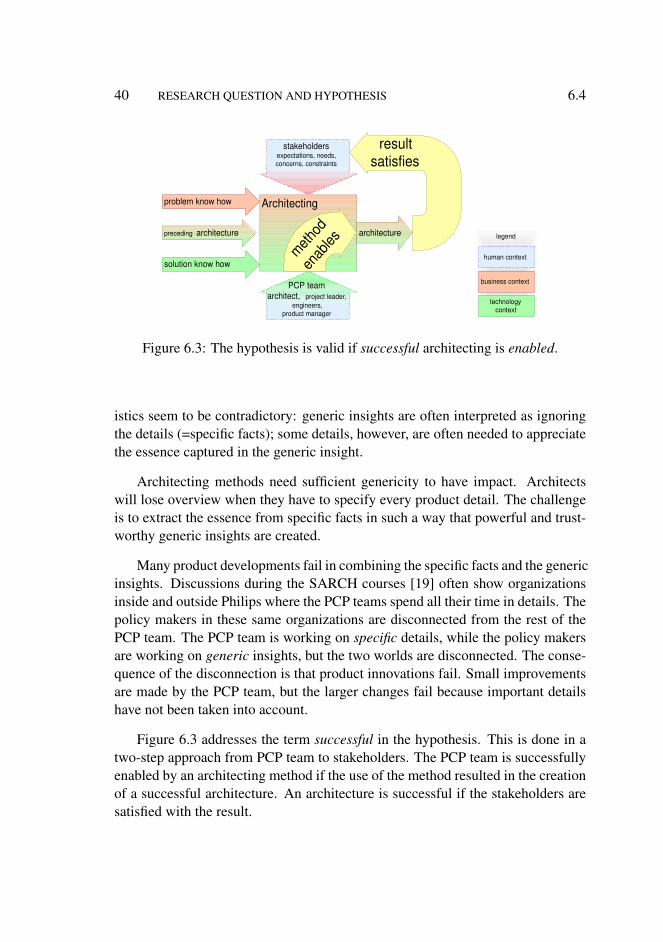
40 RESEARCH QUESTION AND HYPOTHESIS 6.4
preceding architecture
Architecting
architecture
problem know how
solution know how
business context
technology context
result satisfies
method
en
ables
legend
PCP team architect, project leader,
engineers, product manager
stakeholders expectations, needs, concerns, constraints
human context
Figure 6.3: The hypothesis is valid if successful architecting is enabled.
istics seem to be contradictory: generic insights are often interpreted as ignoringthe details (=specific facts); some details, however, are often needed to appreciatethe essence captured in the generic insight.
Architecting methods need sufficient genericity to have impact. Architectswill lose overview when they have to specify every product detail. The challengeis to extract the essence from specific facts in such a way that powerful and trust-worthy generic insights are created.
Many product developments fail in combining the specific facts and the genericinsights. Discussions during the SARCH courses [19] often show organizationsinside and outside Philips where the PCP teams spend all their time in details. Thepolicy makers in these same organizations are disconnected from the rest of thePCP team. The PCP team is working on specific details, while the policy makersare working on generic insights, but the two worlds are disconnected. The conse-quence of the disconnection is that product innovations fail. Small improvementsare made by the PCP team, but the larger changes fail because important detailshave not been taken into account.
Figure 6.3 addresses the term successful in the hypothesis. This is done in atwo-step approach from PCP team to stakeholders. The PCP team is successfullyenabled by an architecting method if the use of the method resulted in the creationof a successful architecture. An architecture is successful if the stakeholders aresatisfied with the result.

6.4 CRITERIA 41
6.4 Criteria
Figure 6.4 shows the criteria to be used, based on the two step approach shown inFigure 6.3.
preceding architecture
Architecting
architecture
Stakeholders expectations, needs, concerns,
constraints
PCP team architect, project leader,
engineers, product manager
problem know how
solution know how
result satisfies
method
en
ables
method enables PCP team to create architecture
3. architects benefit from deploying submethods
4. project leaders , product managers and engineers are able to use the outcome of the submethods
resulting architecture satisfies stakeholders
1. product is a commercial success
2. product family is sustainable commercially successful
Figure 6.4: From hypothesis to criteria
The resulting architecture satisfies the stakeholders is indirectly verified bymeasuring the 1. short term commercial success of the product and the 2. sustain-ability of this commercial success in the following product family. The underlyingassumption is that satisfied customers buy more products and motivate other cus-tomers to buy this satisfactory product. Dissatisfied customers have a negativeimpact on the sales.
In order to exclude incidental success, the long term commercial success isalso required. This long term success can only be measured by means of follow-on products. The active commercial lifetime of products (1 to 2 years) is too shortto measure long term commercial success with the product itself. The follow-onproduct family, based on the same architecture and architecting method, is usedinstead.
The architecting method enables the PCP team to create a successful archi-tecture is sharpened by defining two criteria. The first criterion is for the architectas primary user: the architect(s) must be able to use the submethods to achieve agood architecture. Note that the hypothesis mentions submethods complementedwith reasoning methods. The criterion for success is not that all submethods areuseable, but the criterion is that 3. the architect benefits from the collection ofsubmethods.
The second criterion to assess is the enabling of the product creation team,especially the (non-architect) members of the PCP team: 4. the outcome of thearchitecting method must be usable for the other members of the Product Creation

42 RESEARCH QUESTION AND HYPOTHESIS 6.5
Team (or PCP Team): project leaders, product managers and engineers.The quality of the design of the product contributes to the sustainability of the
product. The quality of design is also one of the measures for the support that themethod provides to architects. Another measure for the support is the integration:How well was integration supported by the chosen integration?
6.5 Summary
In this chapter we have discussed the research question, the objectives of the ar-chitecting method, the hypothesis about the architecting method improvements,and the criteria to evaluate the method. Figure 6.5 shows the summary of thischapter: research question, hypothesis and criteria.
hypothesis
research question
criteria
A rich collection of submethods fitting in a multi-view framework complemented with reasoning methods enables successful architecting of technology
and software intensive complex systems in heterogeneous environments by means of generic insights grounded in specific facts
What architecting methods enable the creation of successful products
in dynamic markets developed in a heterogeneous industrial context
1. product is a commercial success 2. product family is sustainable commercially successful 3. architects benefit from deploying submethods 4. project leaders , product managers and engineers are able to use the
outcome of the submethods
Figure 6.5: Overview of research question, hypothesis and criteria.
Part II will show the theory of the architecting method. Part III describesthe case that is used for the evaluation. In Part IV, in chapters 18 and 19, thehypothesis and criteria are used for the evaluation.
Part II
Theory of CAFCR and Threadsof Reasoning
Chapters in Part II:
7. Basic Methods
8. Submethods in the CAF Views
9. Submethods in the CR Views
10. Qualities as Integrating Needles
11. Story Telling
12. Threads of Reasoning
43

Chapter 7
Basic Methods
7.1 Introduction
The basic methods used by system architects are covered by a limited set of verygeneric patterns:
• Viewpoint hopping, looking at the problem and (potential) solutions frommany points of view, see Section 7.2.
• Decomposition, breaking up a large problem into smaller problems, intro-ducing interfaces and the need for integration, see Section 7.3.
• Quantification, building up understanding by quantification, from order ofmagnitude numbers to specifications with acceptable confidence levels, seeSection 7.4.
• Decision making when lots of data is missing, see Section 7.5.• Modelling, as means of communication, documentation, analysis, simula-
tion, decision making and verification, see Section 7.6.• Asking Why, What, How, Who, When, Where questions, see Section 7.7.• Problem solving approach, see Section 7.8.
Besides these methods the architect needs lots of “soft” skills, to be effec-tive with the large amount of different people involved in creating the system,see [68].
45
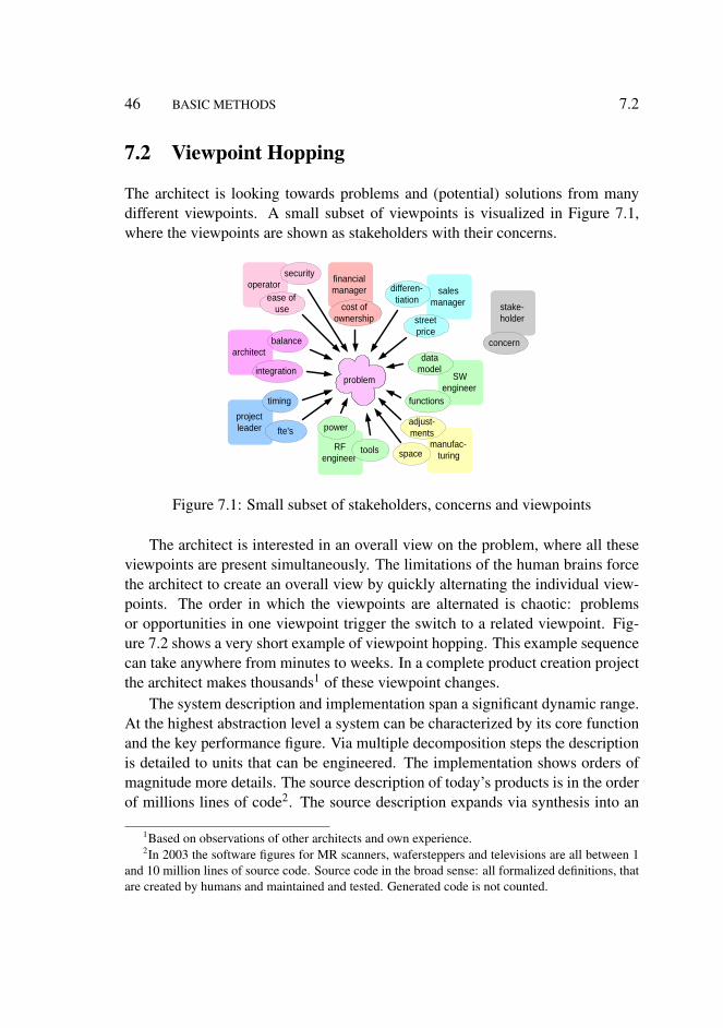
46 BASIC METHODS 7.2
7.2 Viewpoint Hopping
The architect is looking towards problems and (potential) solutions from manydifferent viewpoints. A small subset of viewpoints is visualized in Figure 7.1,where the viewpoints are shown as stakeholders with their concerns.
manufac- turing
SW engineer
RF engineer
project leader
sales manager
operator
problem
security
ease of use
power
tools
differen- tiation
street price
space
adjust- ments
timing
fte's
data model
functions
architect
financial manager
cost of ownership
balance
integration
stake- holder
concern
Figure 7.1: Small subset of stakeholders, concerns and viewpoints
The architect is interested in an overall view on the problem, where all theseviewpoints are present simultaneously. The limitations of the human brains forcethe architect to create an overall view by quickly alternating the individual view-points. The order in which the viewpoints are alternated is chaotic: problemsor opportunities in one viewpoint trigger the switch to a related viewpoint. Fig-ure 7.2 shows a very short example of viewpoint hopping. This example sequencecan take anywhere from minutes to weeks. In a complete product creation projectthe architect makes thousands1 of these viewpoint changes.
The system description and implementation span a significant dynamic range.At the highest abstraction level a system can be characterized by its core functionand the key performance figure. Via multiple decomposition steps the descriptionis detailed to units that can be engineered. The implementation shows orders ofmagnitude more details. The source description of today’s products is in the orderof millions lines of code2. The source description expands via synthesis into an
1Based on observations of other architects and own experience.2In 2003 the software figures for MR scanners, wafersteppers and televisions are all between 1
and 10 million lines of source code. Source code in the broad sense: all formalized definitions, thatare created by humans and maintained and tested. Generated code is not counted.

7.2 VIEWPOINT HOPPING 47
street price timing functions
cost of ownership
SW engineer
project leader
sales manager
financial manager
triggered by : financing costs, part of cost of ownership, are determined by street price.
triggered by : lowering street price and time to market are conflicting. How much margin do we have in timing?
triggered by : timing of the product is determined by SW. A trade-off is possible between functionality and timing.
Figure 7.2: Short example of viewpoint hopping
order magnitude more wires, gates, transistors and bytes. The amount of states inactual operation is again orders of magnitude larger.
Figure 7.3 shows this dynamic range. At the left hand abstraction levels in thecreation life-cycle are shown. Both for hardware and software the typical entitiesat the different layers of abstraction are shown.
system
subsystems
components
10 9
10 6
10 3
1
states
core function
system functions
subsystem functions
lines of code connections, building blocks
wires, gates, transistors bytes
10 nnnn
spec
ifica
tion
desi
gn d
escr
iptio
ns
sour
ce
code
sy
nthe
- si
zed
run-
tim
e
states
hardware software metric # entities
Figure 7.3: Dynamic range of description and implementation in a product
The viewpoints and dynamic range of abstraction create a huge space for ex-ploration. Systematic scanning of this space is way too slow. An architect is usingtwo techniques to scan this space, that are quite difficult to combine: open percep-tive scanning and scanning while structuring and judging. The open perceptive

48 BASIC METHODS 7.3
mode is needed to build understanding and insight. Early structuring and judgingis dangerous because it might become a self-fulfilling prophecy. The structuringand judging is required to reach a result in a limited amount of time and effort.See Figure 7.4 for these 2 modes of scanning.
open perceptive
scanning
scanning while
structuring and judging
drunkard's walk the world is full of interesting
needs, technologies, ...
bad
bad
good
goal
straight for the goal ignore everything
that is not contributing directly to the goal
Figure 7.4: Two modes of scanning by an architect
The scanning approach taken by the architect can be compared with simulatedannealing methods for optimization. An interesting quote from the book “Nu-merical Recipes in C; The Art of Scientific Computing”[66], about comparingoptimization methods is:
Although the analogy is not perfect, there is a sense in which all ofthe minimization algorithms thus far in this chapter correspond torapid cooling or quenching. In all cases, we have gone greedily forthe quick, nearby solution: From the starting point, go immediatelydownhill as far as you can go. This, as often remarked above, leadsto a local, but not necessarily a global, minimum. Nature’s own min-imization algorithm is based on a quite different procedure...
The exploration space is not exclusively covered by the architect(s), engineerswill cover a large part of this space. The architect will focus mostly on the higherabstraction layers, but sufficient sampling of the lower layers is important to keepthe higher layers meaningful.

7.4 DECOMPOSITION AND INTEGRATION 49
7.3 Decomposition and Integration
The architect applies a reduction strategy by means of decomposition over andover. Decomposition is a very generic principle, that can be applied for many dif-ferent problem and solution dimensions. Martin [46] uses the phrase developmentlayers when the decomposition principle is applied on a system.
Whenever something is decomposed the resulting components will be decou-pled by interfaces. The architect will invest time in interfaces, since these providea convenient method to determine system structure and behavior, while separatingthe inside of these components from their external behavior.
The true challenge for the architect is to design decompositions, that in theend will support an integration of components into a system. Most effort of thearchitect is concerned with the integrating concepts, how do multiple componentswork together?
Many stakeholders perceive the decomposition and the interface managementas the most important contribution. In practice it is observed that the synthesis orintegration part is more difficult and time consuming.
7.4 Quantification
The architect is continuously trying to improve his understanding of problem andsolution. This understanding is based on many different interacting insights, suchas functionality, behavior, relationships et cetera. An important factor in under-standing is the quantification. Quantification helps to get grip on the many vagueaspects of problem and solution. Many aspects can be quantified, much more thanmost designers are willing to quantify. Thomas Gilb stresses the importance ofquantification and estimation, see for instance [26].
The precision of the quantification increases during the project. Figure 7.5shows the stepwise refinement of the quantification. In first instance it is importantto get a feeling for the problem by quantifying orders of magnitude. For example:
• How large is the targeted customer population?• What is the amount of money they are willing and able to spend?• How many pictures/movies do they want to store?• How much storage and bandwidth is needed?
The order of magnitude numbers can be refined by making back of the envelopcalculations, making simple models and making assumptions and estimates. From

50 BASIC METHODS 7.4
order of magnitude
guestimates
calibrated estimates
10
50 200
30 300
100 30 300
70 140
90 115
feasibility measure, analyze, simulate
back of the envelope
benchmark, spreadsheet
calculation
99.999 100.001 cycle accurate
Figure 7.5: Successive quantification refined
this work it becomes clear where the major uncertainties are and what measure-ments or other data acquisitions will help to refine the numbers further.
At the bottom of Figure 7.5 the other extreme of the spectrum of quantificationis shown. In this example cycle-accurate simulation of video frame processingresults in very accurate numbers. It is a challenge for an architect to bridge theseworlds.
process overlay 80 nm
reticule 15 nm
matched machine
60 nm
process dependency
sensor 5 nm
matching accuracy
5 nm
single machine
30 nm
lens matching
25 nm
global alignment accuracy
6 nm
stage overlay 12 nm
stage grid accuracy
5 nm
system adjustment accuracy
2 nm
stage Al. pos. meas. accuracy
4 nm
off axis pos. meas.
accuracy 4 nm
metrology stability 5 nm
alignment repro
5 nm
position accuracy
7 nm
frame stability 2.5 nm
tracking error phi 75 nrad
tracking error X, Y 2.5 nm
interferometer
stability 1 nm
blue align sensor repro 3 nm
off axis Sensor repro 3 nm
tracking error WS
2 nm
tracking error RS
1 nm
Figure 7.6: Example of a quantified understanding of overlay in a waferstepper
Figure 7.6 shows a graphical example of an “overlay” budget for a wafer-stepper. This figure is taken from the System Design Specification of the ASML
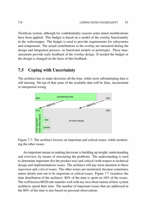
7.6 COPING WITH UNCERTAINTY 51
TwinScan system, although for confidentiality reasons some minor modificationshave been applied. This budget is based on a model of the overlay functionalityin the waferstepper. The budget is used to provide requirements for subsystemsand components. The actual contributions to the overlay are measured during thedesign and integration process, on functional models or prototypes. These mea-surements provide early feedback of the overlay design. If needed the budget orthe design is changed on the basis of this feedback.
7.5 Coping with Uncertainty
The architect has to make decisions all the time, while most substantiating data isstill missing. On top of that some of the available data will be false, inconsistentor interpreted wrong.
architecting time
mos
t im
porta
nt
mos
t crit
ical
issu
es
all other issues
10% 90%
20% 80%
spent on spent on
solved
new
Figure 7.7: The architect focuses on important and critical issues, while monitor-ing the other issues
An important means in making decisions is building up insight, understandingand overview, by means of structuring the problems. The understanding is usedto determine important (for the product use) and critical (with respect to technicaldesign and implementation) issues. The architect will pay most attention to theseimportant and critical issues. The other issues are monitored, because sometimesminor details turn out to be important or critical issues. Figure 7.7 visualizes thetime distribution of the architect: 80% of the time is spent on 10% of the issues.The well known 80/20 rule matches well with my own observations of how systemarchitects spend their time. The number of important issues that are addressed inthe 80% of the time is also based on personal observations.
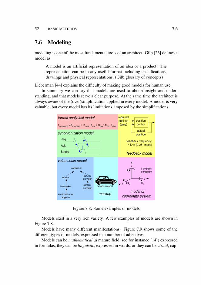
52 BASIC METHODS 7.6
7.6 Modeling
modeling is one of the most fundamental tools of an architect. Gilb [26] defines amodel as
A model is an artificial representation of an idea or a product. Therepresentation can be in any useful format including specifications,drawings and physical representations. (Gilb glossary of concepts)
Lieberman [44] explains the difficulty of making good models for human use.In summary we can say that models are used to obtain insight and under-
standing, and that models serve a clear purpose. At the same time the architect isalways aware of the (over)simplification applied in every model. A model is veryvaluable, but every model has its limitations, imposed by the simplifications.
t processing = t overhead + n rows * t row + n row * n col * t pixel
formal analytical model
Req
Ack
Strobe
synchronization model
position control
actual position
required position (time)
feedback frequency: 4 kHz (0.25 msec)
feedback model
model of coordinate system
semiconductor supplier
box-maker
consumer
retailer service provider
content provider
value chain model
x
y
z
R z
R x R y
6 degrees of freedom
mockup
wooden model
Figure 7.8: Some examples of models
Models exist in a very rich variety. A few examples of models are shown inFigure 7.8.
Models have many different manifestations. Figure 7.9 shows some of thedifferent types of models, expressed in a number of adjectives.
Models can be mathematical (a mature field, see for instance [14]) expressedin formulas, they can be linguistic, expressed in words, or they can be visual, cap-
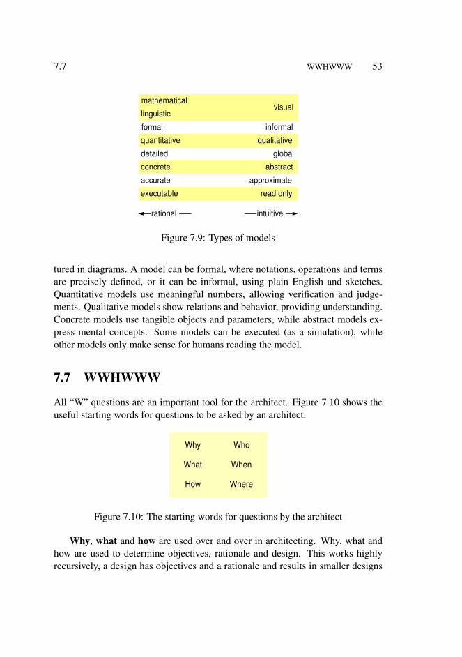
7.7 WWHWWW 53
visual mathematical
linguistic
formal informal
quantitative qualitative
concrete abstract
executable read only
detailed global
accurate approximate
intuitive rational
Figure 7.9: Types of models
tured in diagrams. A model can be formal, where notations, operations and termsare precisely defined, or it can be informal, using plain English and sketches.Quantitative models use meaningful numbers, allowing verification and judge-ments. Qualitative models show relations and behavior, providing understanding.Concrete models use tangible objects and parameters, while abstract models ex-press mental concepts. Some models can be executed (as a simulation), whileother models only make sense for humans reading the model.
7.7 WWHWWW
All “W” questions are an important tool for the architect. Figure 7.10 shows theuseful starting words for questions to be asked by an architect.
Why
What
How
Who
When
Where
Figure 7.10: The starting words for questions by the architect
Why, what and how are used over and over in architecting. Why, what andhow are used to determine objectives, rationale and design. This works highlyrecursively, a design has objectives and a rationale and results in smaller designs

54 BASIC METHODS 7.8
that again have objectives and rationales. Figure 7.11 shows that the recursionwith why questions broadens the scope, and recursion with how questions opensmore details in a smaller scope.
Why What How
Why What How
Why What How
system
context
subsystem
Figure 7.11: Why broadens scope, How opens details
Who, where and when are used somewhat less frequently. Who, where andwhen can be used to build up understanding of the context, and are used in coop-eration with the project leader to prepare the project plan.
7.8 Decision Making Approach in Specification and De-sign
Many specification and design decisions have to be taken during the product cre-ation process. For example, functionality and performance requirements need tobe defined, and the way to realize them has to be chosen. Many of these decisionsare interrelated and have to be taken at a time when many uncertainties still exist,see section 7.5. The need for problem solving and decision making techniquesis clearly recognized in companies like Philips and ASML. Quality improvementprograms in these companies include education in these techniques. The approachdescribed in this section is based on the techniques promoted by the quality im-provement programs.
An approach to make these decisions is the flow depicted in Figure 7.12. Thedecision process is modeled in four steps. An understanding of the problem iscreated by the first step problem understanding, by exploration of problem and
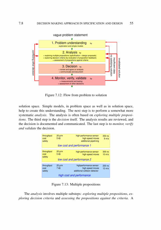
7.8 DECISION MAKING APPROACH IN SPECIFICATION AND DESIGN 55
1. Problem understanding by exploration and simple models
2. Analysis by + exploring multiple propositions (specification + design proposals) + exploring decision criteria (by evaluation of proposition feedback)
+ assessment of propositions against criteria
3. Decision by + review and agree on analysis + communicate and document
4. Monitor, verify, validate by + measurements and testing
+ assessment of other decisions
insufficient data no satisfying solution
invalidated solution
conflicting other decision
vague problem statement
Figure 7.12: Flow from problem to solution
solution space. Simple models, in problem space as well as in solution space,help to create this understanding. The next step is to perform a somewhat moresystematic analysis. The analysis is often based on exploring multiple proposi-tions. The third step is the decision itself. The analysis results are reviewed, andthe decision is documented and communicated. The last step is to monitor, verifyand validate the decision.
low cost and performance 2
throughput cost safety
high-performance sensor high-speed moves
20 p/m 5 k$
300 ns 10 m/s
high cost and performance
throughput cost safety
highperformance sensor high-speed moves
additional collision detector
25 p/m 7 k$
200 ns 12 m/s
low cost and performance 1
throughput cost safety
high-performance sensor high-speed moves
additional pipelining
20 p/m 5 k$
350 ns 9 m/s
Figure 7.13: Multiple propositions
The analysis involves multiple substeps: exploring multiple propositions, ex-ploring decision criteria and assessing the propositions against the criteria. A
56 BASIC METHODS 7.8
proposition describes both specification (what) and design (how). Figure 7.13shows an example of multiple propositions. In this example a high performance,but high cost alternative, is put besides two lower performing alternatives. Mostcriteria get articulated in the discussions about the propositions: “I think that weshould choose proposition 2, because...”. The because can be reconstructed into acriterion.
The decision to chose a proposition is taken on the basis of the analysis re-sults. A review of the analysis results ensures that these results are agreed upon.The decision itself is documented and communicated3. In case of insufficientdata or in absence of a satisfying solution we have to back track to the analysisstep. Sometimes it is better to revisit the problem statement by going back to theunderstanding step.
Taking a decision requires a lot of follow up. The decision is in practice basedon partial and uncertain data, and is based on many assumptions. A significantamount of work is to monitor the consequences and the implementation of the de-cision. Monitoring is partially a soft skill, such as actively listening to engineers,and partially a engineering activity, such as measuring and testing. The conse-quence of a measurement can be that the problem has to be revisited, because thesolution is invalidated. An invalidated solution returns the process to the under-standing step in case of serious mismatches (’apparently we don’t understand theproblem at all’). In case of smaller mismatches the process returns to the analysisstep.
The implementation of taken decisions can be disturbed by later decisions.This problem is partially tackled by requirements traceability, where known in-terdependencies are managed explicitly. In the complex real world the amount ofdependencies is almost infinite, that means that the explicit dependability specifi-cations are inherently incomplete and only partially understood. To cope with theinherent uncertainty about dependabilities, an open mind is needed when screen-ing later decisions. A conflict caused by a later decision triggers a revisit of theoriginal problem.
The same flow of activities is used recursively at different levels of detail, asshown in Figure 7.14. A system problem will result in a system design, wheremany design aspects need the same flow of problem solving activities for the sub-systems. This process is repeated for smaller scopes until termination at problemsthat can be solved directly by an implementation team. The smallest scope oftermination is denoted as atomic level in the figure. Note that the more detailed
3This sounds absolutely trivial, but unfortunately this step is performed quite poorly in practice.

7.8 DECISION MAKING APPROACH IN SPECIFICATION AND DESIGN 57
1. Problem understanding
2. Analysis
3. Decision
4. Monitor, verify, validate
1. Problem understanding
2. Analysis
3. Decision
4. Monitor, verify, validate
1. Problem understanding
2. Analysis
3. Decision
4. Monitor, verify, validate
1. Problem understanding
2. Analysis
3. Decision
4. Monitor, verify, validate
system level
subsystem level
atomic level
component level
analysis flow
decision flow
legend
Figure 7.14: Recursive and concurrent application of flow
problem solving might have impact on the more global decisions.

58 BASIC METHODS 7.8

Chapter 8
Submethods in the CAF Views
8.1 Introduction
This chapter describes the submethods in the Customer objectives, Applicationand Functional views.
Section 8.2 describes a submethod to identify key drivers and to relate the keydrivers to product requirements.
Section 8.3 mentions submethods that help in positioning the business of thecustomer in the context: analysis of the value chain, analysis of business models,creation of a map of competitors and complementers, application context diagramand identification and articulation of the stakeholders and concerns.
The basic methods modeling and quantification from Chapter 7 are used inSection 8.4 to identify useful models in the customer world.
Section 8.5 describes use cases as description and communication means forbehavioral as well as quantitative characteristics.
The leading document in the product creation process is the system specifica-tion, which is discussed in Section 8.6.
Section 8.7 provides an overview of all the submethods discussed in this chap-ter, and positions the submethods in the CAFCR views.
8.2 Key Drivers
The essence of the objectives of the customers can be captured in terms of cus-tomer key drivers. The key drivers provide direction to capture requirements andto focus the development. This method has been successfully deployed to focus
59
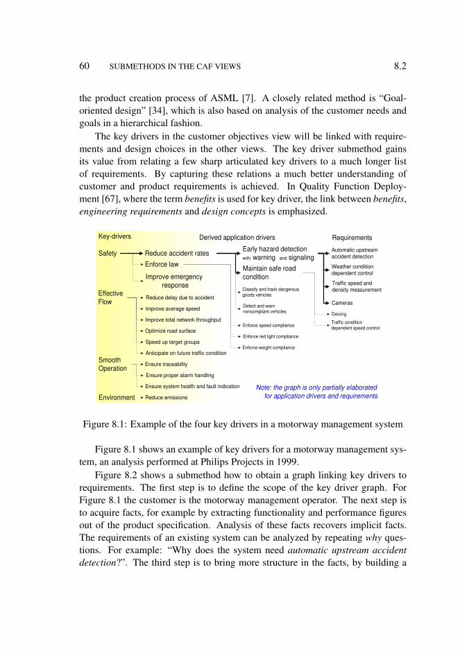
60 SUBMETHODS IN THE CAF VIEWS 8.2
the product creation process of ASML [7]. A closely related method is “Goal-oriented design” [34], which is also based on analysis of the customer needs andgoals in a hierarchical fashion.
The key drivers in the customer objectives view will be linked with require-ments and design choices in the other views. The key driver submethod gainsits value from relating a few sharp articulated key drivers to a much longer listof requirements. By capturing these relations a much better understanding ofcustomer and product requirements is achieved. In Quality Function Deploy-ment [67], where the term benefits is used for key driver, the link between benefits,engineering requirements and design concepts is emphasized.
Safety
Effective Flow
Smooth Operation
Environment
Reduce accident rates
Enforce law
Improve emergency response
Reduce delay due to accident
Improve average speed
Improve total network throughput
Optimize road surface
Speed up target groups
Anticipate on future traffic condition
Ensure traceability
Ensure proper alarm handling
Ensure system health and fault indication
Reduce emissions
Early hazard detection with warning and signaling
Maintain safe road condition
Classify and track dangerous goods vehicles
Detect and warn noncompliant vehicles
Enforce speed compliance
Enforce red light compliance
Enforce weight compliance
Key-drivers Derived application drivers Requirements
Automatic upstream accident detection
Weather condition dependent control
Deicing
Traffic condition dependent speed control
Traffic speed and density measurement
Note: the graph is only partially elaborated for application drivers and requirements
Cameras
Figure 8.1: Example of the four key drivers in a motorway management system
Figure 8.1 shows an example of key drivers for a motorway management sys-tem, an analysis performed at Philips Projects in 1999.
Figure 8.2 shows a submethod how to obtain a graph linking key drivers torequirements. The first step is to define the scope of the key driver graph. ForFigure 8.1 the customer is the motorway management operator. The next step isto acquire facts, for example by extracting functionality and performance figuresout of the product specification. Analysis of these facts recovers implicit facts.The requirements of an existing system can be analyzed by repeating why ques-tions. For example: “Why does the system need automatic upstream accidentdetection?”. The third step is to bring more structure in the facts, by building a

8.2 KEY DRIVERS 61
• Build a graph of relations between drivers and requirements by means of brainstorming and discussions
• Define the scope specific. in terms of stakeholder or market segments
• Acquire and analyze facts extract facts from the product specification a nd ask why questions about the specification of existing products .
• Iterate many times increased understanding often triggers the move of issues
from driver to requirement or vice versa and rephrasing
where requirements may have multiple drivers
• Obtain feedback discuss with customers , observe their reactions
Figure 8.2: Submethod to link key drivers to requirements, existing of the iterationover four steps
graph, which connects requirements to key drivers. A workshop with brainstormsand discussions is an effective way to obtain the graph. The last step is to ob-tain feedback from customers. The total graph can have many n:m relations, i.e.requirements that serve many drivers and drivers that are supported by many re-quirements. The graph is good if the customers are enthusiastic about the keydrivers and the derived application drivers. If a lot of explaining is required thenthe understanding of the customer is far from complete. Frequent iterations overthese steps improves the quality of the understanding of the customer’s viewpoint.Every iteration causes moves of elements in the graph in driver or requirementdirection and also causes rephrasing of elements in the graph.
• Use short names, recognized by the customer.
• Limit the number of key-drivers minimal 3 , maximal 6
for instance the well-known main function of the product • Don’t leave out the obvious key-drivers
for instance replace “ ease of use ” by “ minimal number of actions for experienced users ”,
or “ efficiency ” by “ integral cost per patient ”
• Use market-/customer- specific names, no generic names
• Do not worry about the exact boundary between Customer Objective and Application
create clear goal means relations
Figure 8.3: Recommendations for applying the key driver submethod
Figure 8.3 shows an additional set of recommendations for applying the keydriver submethod. The most important goals of the customer are obtained by lim-iting the number of key drivers. In this way the participants in the discussion are

62 SUBMETHODS IN THE CAF VIEWS 8.3
forced to make choices. The focus in product innovation is often on differenti-ating features, or unique selling points. As a consequence, the core functionalityfrom the customer’s point of view may get insufficient attention. An example ofthis are cell phones that are overloaded with features, but that have a poor userinterface to make connections. The core functionality must be dominantly presentin the graph. The naming used in the graph must fit in the customer world and beas specific as possible. Very generic names tend to be true, but they do not help toreally understand the customer’s viewpoint. The boundary between the CustomerObjectives view and the Application view is not very sharp. When creating thegraph that relates key drivers to requirements one frequently experiences that akey driver is phrased in terms of a (partial) solution. If this happens either the keydriver has to be rephrased or the solution should be moved to the requirement (oreven realization) side of the graph. A repetition of this kind of iterations increasesthe insight in the needs of the customer in relation to the characteristics of theproduct. The why, what and how questions can help to rephrase drivers and re-quirements. The graph is good if the relations between goals and means are clearfor all stakeholders.
8.3 Customer Business Positioning
The position of the customer in the value chain and the business models [63]deployed by the players in the value chain are important factors in understandingthe goals of this customer. The analysis of the value chain of the customer andthe analysis of the business models involved have been deployed as successfulsubmethods in the Medical Systems, Consumer Electronics and Semiconductorsproduct divisions in Philips.
Related to the value chain is the way the customers view their suppliers. Thecustomer sees your company as one of the (potential) suppliers. From the cus-tomer’s point of view products from many suppliers have to be integrated to createthe total solution for his needs. In terms of your own company this means that youhave to make a map of competitors and complementers, that together will supplythe solution to the customer. Figure 8.4 shows an example of a map of competitorsand complementers in the medical domain taken from [58].
An application context diagram is a diagram that shows all systems that canbe operational in the application context. The application context diagram em-phasizes the provided functionality. Many systems in the customer domain haveno direct interface with the product under consideration. The interaction of sys-

8.3 CUSTOMER BUSINESS POSITIONING 63
Hospital
Radiology Cardiology …
W Medical Systems
Peripheral Supplier
IT Integrator
Field Service Provider
Software Supplier
Component Supplier
Medical Systems
Medical Systems
Complementers (can also be competitors) Competitors
From: COPA tutorial; WICSA 2001
Figure 8.4: Example map of competitors and complementers from the medicaldomain
tems in the context with the product happens in many cases via human operators.The value of such a diagram is to understand function allocation in the customercontext and to understand the value of potential improvements, such as furtherintegration or automation.
Figure 8.5 shows a simple context diagram of the motorway management sys-tem of Figure 8.1. Tunnels and toll stations often have their own local manage-ment systems, although they are part of the same motorway. The motorway isconnecting destinations, such as urban areas. Urban areas have many traffic sys-tems, such as traffic management (traffic lights) and parking systems. For everysystem in the context questions can be asked, such as:
• is there a need to interface directly (e.g. show parking information to peoplestill on the highway)?
• is duplication of functionality required (measuring traffic density and send-ing it to a traffic control center) or not?
The map of competitors and complementers focuses on economic parties andtheir roles, while the application context diagram focuses on the functional oper-ation in the customer context.
The IEEE 1471 [6] standard about architectural descriptions uses stakeholdersand concerns as the starting point for an architectural description. Identificationand articulation of the stakeholders and concerns is a first step in understand-ing the application domain. This approach matches very well with the CAFCR

64 SUBMETHODS IN THE CAF VIEWS 8.4
motorway management
system restaurants gas stations
bus lanes lorry lanes
maintenance contractors
taxes car administration government
airports railways toll
tunnel
car repair towing service
fleet management urban traffic control advanced vehicle control
environmental monitoring
Figure 8.5: Systems in the context of a motorway management system
approachIn practice the informal relationships get insufficient attention. In many cases
the formal relationships, such as organization charts and process descriptions, aresolely used for the analysis of the stakeholders and their concerns. The under-standing of the customer context is then incomplete, often causing the failure ofthe solution. Many organizations function thanks to the unwritten informationflows of the social system. Insight in the informal side is required to prevent asolution that does only work in theory.
8.4 Modeling in the Customer World
The customer context can be statically modelled by deploying modeling tech-niques from the information technology world, for instance entity relationshipdiagrams [29].
Dynamic models are used to model the logical behavior or the behavior intime. Examples of dynamic models are shown in Figure 8.6:
• flow models that model the flow of goods, people or information• state diagrams make the dynamics explicit by means of states and state tran-
sitions -• time line that show the events as a function of time
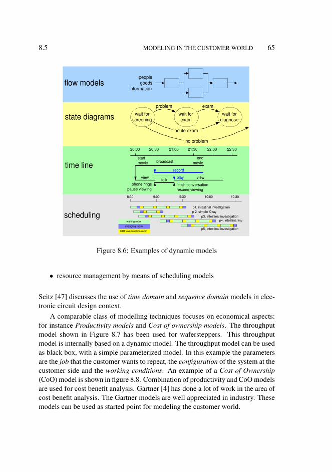
8.5 MODELING IN THE CUSTOMER WORLD 65
scheduling
flow models people goods
information
wait for screening
wait for diagnose
problem exam
acute exam
no problem
wait for exam state diagrams
20:00 20:30 21:00 21:30 22:00 22:30
broadcast
phone rings pause viewing
finish conversation resume viewing
start movie
end movie
view view talk
record
play
time line
p1, intestinal investigation p 2, simple X-ray
p3, intestinal investigation p4, intestinal inv
p5, intestinal investigation
8:30 9:00 9:30 10:00 10:30
URF examination room
changing room
waiting room
Figure 8.6: Examples of dynamic models
• resource management by means of scheduling models
Seitz [47] discusses the use of time domain and sequence domain models in elec-tronic circuit design context.
A comparable class of modelling techniques focuses on economical aspects:for instance Productivity models and Cost of ownership models. The throughputmodel shown in Figure 8.7 has been used for wafersteppers. This throughputmodel is internally based on a dynamic model. The throughput model can be usedas black box, with a simple parameterized model. In this example the parametersare the job that the customer wants to repeat, the configuration of the system at thecustomer side and the working conditions. An example of a Cost of Ownership(CoO) model is shown in figure 8.8. Combination of productivity and CoO modelsare used for cost benefit analysis. Gartner [4] has done a lot of work in the area ofcost benefit analysis. The Gartner models are well appreciated in industry. Thesemodels can be used as started point for modeling the customer world.

66 SUBMETHODS IN THE CAF VIEWS 8.5
waferstepper throughput model
wafer throughput
lithography job required dose field size field map alignment procedure
Figure 8.7: A throughput model that estimates the throughput as function of usercontrolled values
personnel
consumables
service
facilities
financing 10
20
30
40
50
60 radiologist
nurse
security administration
operator
Cost Of Ownership model
k$
Figure 8.8: Example of a Cost of Ownership model
8.5 Use Cases
Use cases [16] are widely used in software development to describe how the sys-tem is used. Most software people use the use case submethod only for behavioraldescriptions. In embedded systems design this submethod is also very useful forquantitative descriptions of the system, for instance for performance.
Figure 8.9 shows a classification of use cases, with several examples from thePersonal Video Recorder (PVR) domain per category. The most typical use ofa PVR is to watch movies: find the desired movie and play it. Additional fea-tures are the possibility to pause or to stop and to skip forward or backward. Theuse case description itself should describe exactly the required functionality. Therequired non-functional aspects, such as performance, reliability and exceptionalbehavior must be described as well.
Typical use cases describe the core requirements of the products. The bound-aries of the product must be described as well. These boundaries can be simplyspecified (for example, maximum amount of video stored is 20 hours standard
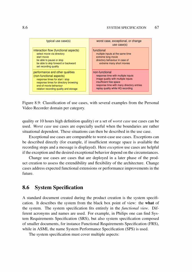
8.6 SYSTEM SPECIFICATION 67
worst case, exceptional, or change use case(s)
typical use case(s)
interaction flow (functional aspects) select movie via directory start movie be able to pause or stop be able to skip forward or backward set recording quality
performance and other qualities (non-functional aspects)
response times for start / stop response times for directory browsing end-of-movie behaviour relation recording quality and storage
functional multiple inputs at the same time extreme long movie directory behaviour in case of
extreme many short movies
non-functional response time with multiple inputs image quality with multiple inputs insufficient free space response time with many directory entries replay quality while HQ recording
Figure 8.9: Classification of use cases, with several examples from the PersonalVideo Recorder domain per category.
quality or 10 hours high definition quality) or a set of worst case use cases can beused. Worst case use cases are especially useful when the boundaries are rathersituational dependent. These situations can then be described in the use case.
Exceptional use cases are comparable to worst-case use cases. Exceptions canbe described directly (for example, if insufficient storage space is available therecording stops and a message is displayed). Here exception use cases are helpfulif the exception and the desired exceptional behavior depend on the circumstances.
Change use cases are cases that are deployed in a later phase of the prod-uct creation to assess the extendibility and flexibility of the architecture. Changecases address expected functional extensions or performance improvements in thefuture.
8.6 System Specification
A standard document created during the product creation is the system specifi-cation. It describes the system from the black box point of view: the what ofthe system. The system specification fits entirely in the functional view. Dif-ferent acronyms and names are used. For example, in Philips one can find Sys-tem Requirements Specification (SRS), but also system specification composedof smaller documents, for instance Functional Requirements Specification (FRS),while in ASML the name System Performance Specification (SPS) is used.
The system specification must cover multiple aspects:
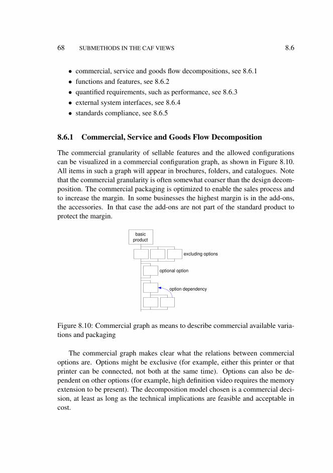
68 SUBMETHODS IN THE CAF VIEWS 8.6
• commercial, service and goods flow decompositions, see 8.6.1• functions and features, see 8.6.2• quantified requirements, such as performance, see 8.6.3• external system interfaces, see 8.6.4• standards compliance, see 8.6.5
8.6.1 Commercial, Service and Goods Flow Decomposition
The commercial granularity of sellable features and the allowed configurationscan be visualized in a commercial configuration graph, as shown in Figure 8.10.All items in such a graph will appear in brochures, folders, and catalogues. Notethat the commercial granularity is often somewhat coarser than the design decom-position. The commercial packaging is optimized to enable the sales process andto increase the margin. In some businesses the highest margin is in the add-ons,the accessories. In that case the add-ons are not part of the standard product toprotect the margin.
basic product
excluding options
optional option
option dependency
Figure 8.10: Commercial graph as means to describe commercial available varia-tions and packaging
The commercial graph makes clear what the relations between commercialoptions are. Options might be exclusive (for example, either this printer or thatprinter can be connected, not both at the same time). Options can also be de-pendent on other options (for example, high definition video requires the memoryextension to be present). The decomposition model chosen is a commercial deci-sion, at least as long as the technical implications are feasible and acceptable incost.
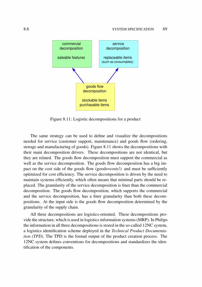
8.6 SYSTEM SPECIFICATION 69
commercial decomposition
saleable features
service decomposition
replaceable items (such as consumables)
goods flow decomposition
stockable items purchasable items
Figure 8.11: Logistic decompositions for a product
The same strategy can be used to define and visualize the decompositionsneeded for service (customer support, maintenance) and goods flow (ordering,storage and manufacturing of goods). Figure 8.11 shows the decompositions withtheir main decomposition drivers. These decompositions are not identical, butthey are related. The goods flow decomposition must support the commercial aswell as the service decomposition. The goods flow decomposition has a big im-pact on the cost side of the goods flow (goods=costs!) and must be sufficientlyoptimized for cost efficiency. The service decomposition is driven by the need tomaintain systems efficiently, which often means that minimal parts should be re-placed. The granularity of the service decomposition is finer than the commercialdecomposition. The goods flow decomposition, which supports the commercialand the service decomposition, has a finer granularity than both these decom-positions. At the input side is the goods flow decomposition determined by thegranularity of the supply chain.
All three decompositions are logistics-oriented. These decompositions pro-vide the structure, which is used in logistics information systems (MRP). In Philipsthe information in all three decompositions is stored in the so-called 12NC system,a logistics identification scheme deployed in the Technical Product Documenta-tion (TPD). The TPD is the formal output of the product creation process. The12NC system defines conventions for decompositions and standardizes the iden-tification of the components.
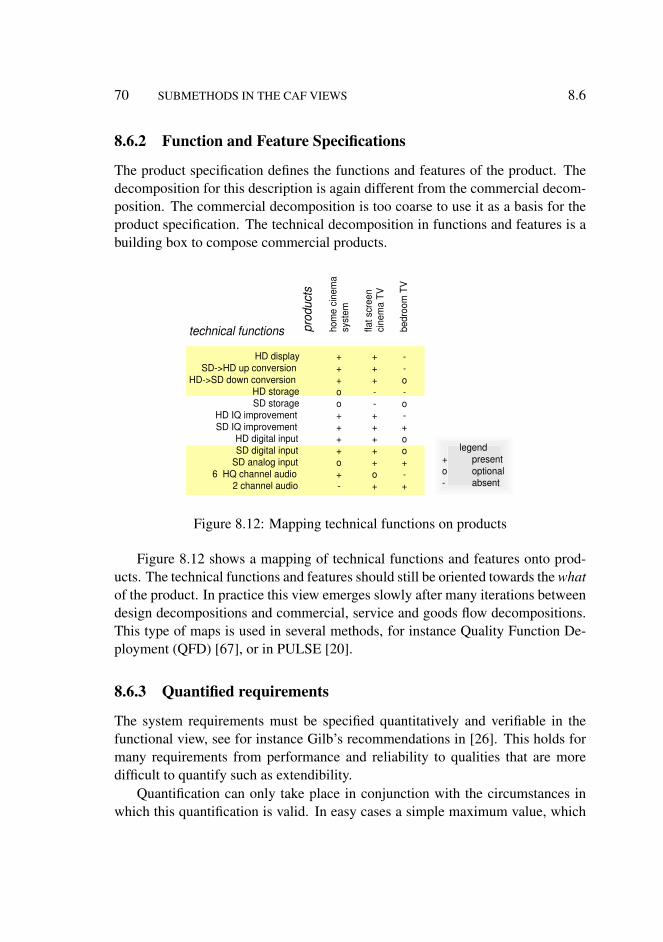
70 SUBMETHODS IN THE CAF VIEWS 8.6
8.6.2 Function and Feature Specifications
The product specification defines the functions and features of the product. Thedecomposition for this description is again different from the commercial decom-position. The commercial decomposition is too coarse to use it as a basis for theproduct specification. The technical decomposition in functions and features is abuilding box to compose commercial products.
technical functions
HD display SD->HD up conversion
HD->SD down conversion HD storage SD storage
HD IQ improvement SD IQ improvement
HD digital input SD digital input
SD analog input 6 HQ channel audio
2 channel audio
prod
ucts
hom
e ci
nem
a sy
stem
flat s
cree
n ci
nem
a TV
bedr
oom
TV
+ + + o o + + + + o + -
+ + + - - + + + + + o +
- - o - o - + o o + - +
legend + present o optional - absent
Figure 8.12: Mapping technical functions on products
Figure 8.12 shows a mapping of technical functions and features onto prod-ucts. The technical functions and features should still be oriented towards the whatof the product. In practice this view emerges slowly after many iterations betweendesign decompositions and commercial, service and goods flow decompositions.This type of maps is used in several methods, for instance Quality Function De-ployment (QFD) [67], or in PULSE [20].
8.6.3 Quantified requirements
The system requirements must be specified quantitatively and verifiable in thefunctional view, see for instance Gilb’s recommendations in [26]. This holds formany requirements from performance and reliability to qualities that are moredifficult to quantify such as extendibility.
Quantification can only take place in conjunction with the circumstances inwhich this quantification is valid. In easy cases a simple maximum value, which
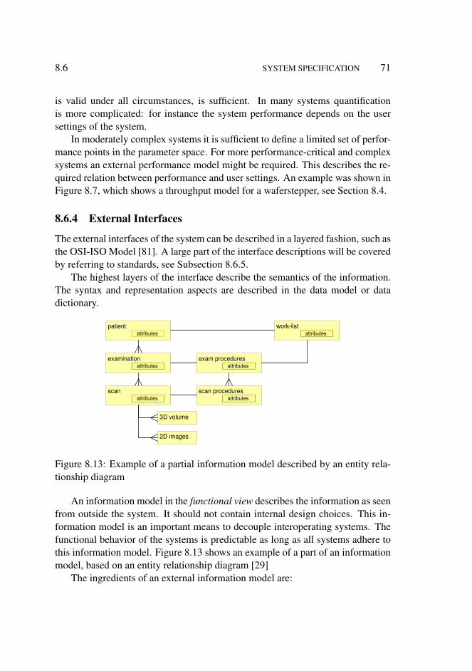
8.6 SYSTEM SPECIFICATION 71
is valid under all circumstances, is sufficient. In many systems quantificationis more complicated: for instance the system performance depends on the usersettings of the system.
In moderately complex systems it is sufficient to define a limited set of perfor-mance points in the parameter space. For more performance-critical and complexsystems an external performance model might be required. This describes the re-quired relation between performance and user settings. An example was shown inFigure 8.7, which shows a throughput model for a waferstepper, see Section 8.4.
8.6.4 External Interfaces
The external interfaces of the system can be described in a layered fashion, such asthe OSI-ISO Model [81]. A large part of the interface descriptions will be coveredby referring to standards, see Subsection 8.6.5.
The highest layers of the interface describe the semantics of the information.The syntax and representation aspects are described in the data model or datadictionary.
patient
examination
scan
2D images
3D volume
attributes
scan procedures
exam procedures
attributes
attributes
attributes
attributes work-list
attributes
Figure 8.13: Example of a partial information model described by an entity rela-tionship diagram
An information model in the functional view describes the information as seenfrom outside the system. It should not contain internal design choices. This in-formation model is an important means to decouple interoperating systems. Thefunctional behavior of the systems is predictable as long as all systems adhere tothis information model. Figure 8.13 shows an example of a part of an informationmodel, based on an entity relationship diagram [29]
The ingredients of an external information model are:
72 SUBMETHODS IN THE CAF VIEWS 8.6
• entities• relations between entities• operations on entities
The most difficult part of the information model is to capture the semanticsof the information. An information model defines the intended meaning of theinformation, in terms of entities, their meaning, the relation with other entitiesand possible operations that can be applied on these entities. Often other meansare required as well such as an ontology, conventions for semantics, and formalnotations.
The technical details of the information model, such as exact identifiers, datatypes and ranges are defined in the datamodel. The term data dictionary is alsooften used for this lower level of definitions.
8.6.5 Standards
Compliance with standards is part of the product specification. The level of com-pliance and possible exceptions need to be specified. Duplication of informationin the standard must be avoided, because redundancy creates more maintenancework and increases the chance of inconsistencies in the specification. The nicecharacteristic of standards in general is that the standards are extensively describedand well defined. An implementation that follows a standard is often straightfor-ward engineering work, without the uncertainty of most other parts of the productspecification.
Architecting work is, nevertheless, required in deciding on standards and indesigning the implementation. Figure 8.14 shows the forces working upon theselection of standards. The market and business environment more or less dictate aset of standards. If the product does not comply with those standards the system isnot viable. Some of these standards are mandatory due to legislation (for instancemandated by the VDE in Germany or the FDA in the United States), others are defacto musts (for instance DICOM, the medical imaging communication standard).
The use of the standard and the compliance level depend on the intended use.A key question for the architect is: What is the intention of the standard? Stan-dards are created by domain experts. The domain experts make all kinds of con-ceptual assumptions. Using a standard in a way that does not correspond well withthese assumptions, can create many specification and design problems. Good un-derstanding of the underlying conceptual assumptions is a must for the architect.
The standard can have significant implementation consequences, for instance

8.6 SYSTEM SPECIFICATION 73
well defined standards and legislation
FDA
HL7 DICOM
HIPAA
VDE ISO 9001
EMC
business objectives
application intention?
realization consequences
conceptual assumptions
but many thousands of pages
Figure 8.14: The standards compliance in the functional view in a broader forcefield.
in the amount of effort needed or the amount of license costs involved in creat-ing the implementation. These costs must be balanced with the created customervalue.
A major problem with standards compliance is the massive amount of docu-mentation and know-how that is involved. The architect must find out the essencein terms of objectives, intention, assumptions and consequences of standards. Infact the architect must have a CAFCR mental model per standard1. For communi-cation purposes the architect can make this model explicit.
1the CAFCR model describes in fact the architecture of the standard itself.
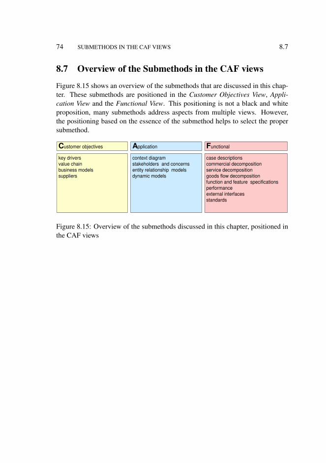
74 SUBMETHODS IN THE CAF VIEWS 8.7
8.7 Overview of the Submethods in the CAF views
Figure 8.15 shows an overview of the submethods that are discussed in this chap-ter. These submethods are positioned in the Customer Objectives View, Appli-cation View and the Functional View. This positioning is not a black and whiteproposition, many submethods address aspects from multiple views. However,the positioning based on the essence of the submethod helps to select the propersubmethod.
C ustomer objectives A pplication F unctional
key drivers value chain business models suppliers
context diagram stakeholders and concerns entity relationship models dynamic models
case descriptions commercial decomposition service decomposition goods flow decomposition function and feature specifications performance external interfaces standards
Figure 8.15: Overview of the submethods discussed in this chapter, positioned inthe CAF views
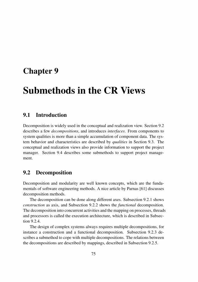
Chapter 9
Submethods in the CR Views
9.1 Introduction
Decomposition is widely used in the conceptual and realization view. Section 9.2describes a few decompositions, and introduces interfaces. From components tosystem qualities is more than a simple accumulation of component data. The sys-tem behavior and characteristics are described by qualities in Section 9.3. Theconceptual and realization views also provide information to support the projectmanager. Section 9.4 describes some submethods to support project manage-ment.
9.2 Decomposition
Decomposition and modularity are well known concepts, which are the funda-mentals of software engineering methods. A nice article by Parnas [61] discussesdecomposition methods.
The decomposition can be done along different axes. Subsection 9.2.1 showsconstruction as axis, and Subsection 9.2.2 shows the functional decomposition.The decomposition into concurrent activities and the mapping on processes, threadsand processors is called the execution architecture, which is described in Subsec-tion 9.2.4.
The design of complex systems always requires multiple decompositions, forinstance a construction and a functional decomposition. Subsection 9.2.3 de-scribes a submethod to cope with multiple decompositions. The relations betweenthe decompositions are described by mappings, described in Subsection 9.2.5.
75

76 SUBMETHODS IN THE CR VIEWS 9.2
Decompositions results in components. The interfacing between componentsis discussed in Subsection 9.2.6.
9.2.1 Construction Decomposition
The construction decomposition views the system from the construction point ofview, see Figure 9.1 for an example. In this example the decomposition is struc-tured to show layers and the degree of domain know-how. The vertical layeringdefines the dependencies: components in the higher layers depend on componentsin the lower layers. Components are not dependent on components at the sameor higher layer. The amount of domain know how provides an indication of theadded value of the components. More generic components are more likely to beshared in a broader application area, and are more likely to be purchased insteadof being developed.
tuner frame- buffer MPEG DSP CPU RAM
drivers scheduler OS
etc
audio video TXT file- system networking etc.
view PIP
browse viewport menu
adjust view TXT
hardware
driver
applications
services toolboxes
domain specific generic
signal processing subsystem control subsystem
Figure 9.1: Example of a construction decomposition of a simple TV. The verti-cal axis is used for layers, where higher layers depend on lower layers, but notvice versa. In horizontal direction the left hand side shows the domain specificcomponents, the right hand side shows the more generic components.
The construction decomposition is mostly used for the design management.It defines units of design, as these are created and stored in repositories and laterupdated. The atomic units are aggregated into compound design units. In soft-ware the compound design units are often called packages, in hardware they arecalled modules. The blocks in Figure 9.1 are at the level of these packages andmodules. Packages and modules are used as unit for testing and release and theyoften coincide with organizational ownership and responsibility.

9.2 DECOMPOSITION 77
In hardware this is quite often a very natural decomposition, for instance intocabinets, racks, boards and finally integrated circuits, Intellectual property (IP)cores and cells. The components in the hardware are very tangible. The relation-ship with a number of other decompositions is reasonably one to one, for instancewith the work breakdown for project management purposes.
The construction decomposition in software is more ambiguous. The structureof the code repository and the supporting build environment comes close to thehardware equivalent. Here files and packages are the aggregating constructionlevels. This decomposition is less tangible than the hardware decomposition andthe relationship with other decompositions is sometimes more complex.
9.2.2 Functional Decomposition
The functional decomposition decomposes end user functions into more elemen-tary functions. The elementary functions are internal, the decomposition in el-ementary functions is not easily observable from outside the system. In otherwords, the what is worked out in how. Be aware of the fact that the word functionin system design is heavily overloaded. No attempt is made to define the func-tional decomposition more sharply, because a sharper definition does not providemore guidance to architects. Main criterium for a good functional decompositionis its useability for design. A functional decomposition provides insight how thesystem will accomplish its job. MASCOT [9] is an example of a method where afunctional decomposition is based on data flow.
storage
acquisition processing compress encoding
display processing
de- compress decoding display
acquisition
Figure 9.2: Example functional decomposition camera type device
Figure 9.2 shows an example of (part of) a functional decomposition for acamera type device. It shows a data flow with communication, processing, and
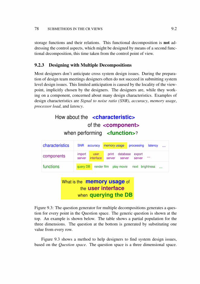
78 SUBMETHODS IN THE CR VIEWS 9.2
storage functions and their relations. This functional decomposition is not ad-dressing the control aspects, which might be designed by means of a second func-tional decomposition, this time taken from the control point of view.
9.2.3 Designing with Multiple Decompositions
Most designers don’t anticipate cross system design issues. During the prepara-tion of design team meetings designers often do not succeed in submitting systemlevel design issues. This limited anticipation is caused by the locality of the view-point, implicitly chosen by the designers. The designers are, while they work-ing on a component, concerned about many design characteristics. Examples ofdesign characteristics are Signal to noise ratio (SNR), accuracy, memory usage,processor load, and latency.
memory usage
export server
print server
database server
SNR accuracy latency processing
brightness next play movie render film query DB
What is the memory usage of the user interface
when querying the DB
import server
user interface
when performing <function> ?
of the <component> How about the <characteristic>
characteristics
components
functions
...
...
...
Figure 9.3: The question generator for multiple decompositions generates a ques-tion for every point in the Question space. The generic question is shown at thetop. An example is shown below. The table shows a partial population for thethree dimensions. The question at the bottom is generated by substituting onevalue from every row.
Figure 9.3 shows a method to help designers to find system design issues,based on the Question space. The question space is a three dimensional space.

9.2 DECOMPOSITION 79
Two dimensions are the decomposition dimensions (construction and functional);the last dimension is the design characteristic dimension. The design characteris-tics on this axis must be specific and quantifiable. A source of inspiration to findthese characteristics are the qualities, described in Chapter 10, where the chal-lenge is to find the specific and quantified characteristics that contribute to thequality.
For every point in this 3D space a question can be generated in the followingway:How about the <characteristic> of the <component> when performing <func-tion>?Which will result in questions like:How about the memory usage of the user interface when querying the database?
The designers will not be able to answer most of these questions. Simplyasking these questions helps the designer to change the viewpoint and discovermany potential issues. Fortunately, most of the (not answered) questions turnout to be irrelevant. The answer to the memory usage question above might beinsignificant or small. The more detailed memory usage questions are irrelevantas long as the total functionality fits in the available memory.
The architect can apply a priori know-how to select the most relevant questionsin the 3D space, for instance:
Critical for system performance Every question that is directly related to criti-cal aspects of the system performance is relevant. For example What is theCPU load of the motion compensation function in the streaming subsystem?will be relevant for resource constrained systems.
Risk planning wise Questions regarding critical planning issues are also rele-vant. For example Will all concurrent streaming operations fit within thedesigned resources? will greatly influence the planning if resources have tobe added.
Least robust part of the design Some parts of the design are known to be rathersensitive, for instance the priority settings of threads. Satisfactory answersshould be available, where a satisfactory answer might also be we scheduleda priority tuning phase, with the following approach.
Suspect parts of the design Other parts of the design may be suspect for a num-ber of reasons. Experience, for instance, learns that response times and
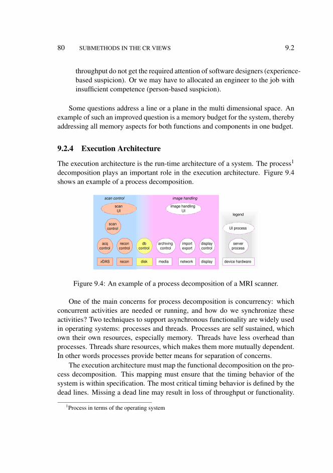
80 SUBMETHODS IN THE CR VIEWS 9.2
throughput do not get the required attention of software designers (experience-based suspicion). Or we may have to allocated an engineer to the job withinsufficient competence (person-based suspicion).
Some questions address a line or a plane in the multi dimensional space. Anexample of such an improved question is a memory budget for the system, therebyaddressing all memory aspects for both functions and components in one budget.
9.2.4 Execution Architecture
The execution architecture is the run-time architecture of a system. The process1
decomposition plays an important role in the execution architecture. Figure 9.4shows an example of a process decomposition.
image handling scan control
scan control
acq control
recon control
x DAS recon
db control
disk
scan UI
image handling UI
archiving control
media
import export
network
display control
display device hardware
server process
UI process
legend
Figure 9.4: An example of a process decomposition of a MRI scanner.
One of the main concerns for process decomposition is concurrency: whichconcurrent activities are needed or running, and how do we synchronize theseactivities? Two techniques to support asynchronous functionality are widely usedin operating systems: processes and threads. Processes are self sustained, whichown their own resources, especially memory. Threads have less overhead thanprocesses. Threads share resources, which makes them more mutually dependent.In other words processes provide better means for separation of concerns.
The execution architecture must map the functional decomposition on the pro-cess decomposition. This mapping must ensure that the timing behavior of thesystem is within specification. The most critical timing behavior is defined by thedead lines. Missing a dead line may result in loss of throughput or functionality.
1Process in terms of the operating system

9.2 DECOMPOSITION 81
The timing behavior is also determined by the choice of the synchronization meth-ods, by the granularity of synchronization and by the scheduling behavior. Themost common technique to control the scheduling behavior is by means of priori-ties. This requires, of course, that priorities are assigned. Subsystems with limitedconcurrency complexity may not even need multiple threads, but these subsystemscan use a single thread that keeps repeating the same actions all the time. Themapping is further influenced by hardware software allocation choices, and by theconstruction decomposition. A well known method in the hard real time domain isDARTS (Design Approach for Real Time Systems) [27]. This methods providesguidelines to identify hard real time requirements, translate them in activities andto map activities on tasks. DARTS then describes how to design the schedulingpriorities.
In practice many components from the construction decomposition are usedin multiple functions, and are mapped on multiple processes. These shared com-ponents are aggregated in shared or dynamic-link libraries (dll’s). Sharing theprogram code run-time is advantageous from memory consumption point of view.
9.2.5 Relations between Decompositions
The decompositions that are made as part of the design are related to each other.A mapping or allocation is required to relate a decomposition with another de-composition. For instance the functional decomposition can be mapped on theconstruction decomposition: functions are allocated to components in the con-struction decomposition. Another example is that functions are mapped on threadsin the execution architecture.
The difficult aspect of these mappings is that in most systems n : m mappingsare needed. Every decompositions serves its own purposes, such as constructionand configuration management in the construction decomposition, performanceand image quality in the data flow functional decomposition, and timing and con-currency in the execution architecture. Each decomposition must clearly serve itsintended purpose. On top of that a clear mapping strategy must be described torelate the decompositions.
9.2.6 Interfaces
The interfaces are the complement of the components in a decomposition. A lotof work on interface specifications has been done, for instance in KOALA [78].KOALA adds the notion of provides and requires interfaces to formalize depen-
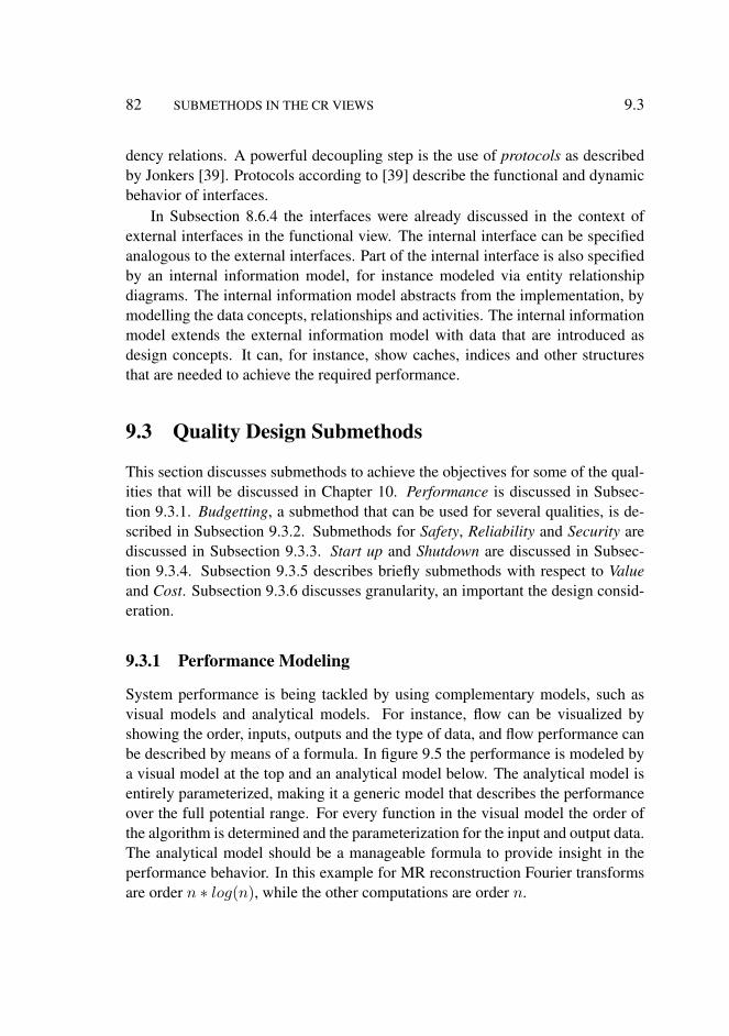
82 SUBMETHODS IN THE CR VIEWS 9.3
dency relations. A powerful decoupling step is the use of protocols as describedby Jonkers [39]. Protocols according to [39] describe the functional and dynamicbehavior of interfaces.
In Subsection 8.6.4 the interfaces were already discussed in the context ofexternal interfaces in the functional view. The internal interface can be specifiedanalogous to the external interfaces. Part of the internal interface is also specifiedby an internal information model, for instance modeled via entity relationshipdiagrams. The internal information model abstracts from the implementation, bymodelling the data concepts, relationships and activities. The internal informationmodel extends the external information model with data that are introduced asdesign concepts. It can, for instance, show caches, indices and other structuresthat are needed to achieve the required performance.
9.3 Quality Design Submethods
This section discusses submethods to achieve the objectives for some of the qual-ities that will be discussed in Chapter 10. Performance is discussed in Subsec-tion 9.3.1. Budgetting, a submethod that can be used for several qualities, is de-scribed in Subsection 9.3.2. Submethods for Safety, Reliability and Security arediscussed in Subsection 9.3.3. Start up and Shutdown are discussed in Subsec-tion 9.3.4. Subsection 9.3.5 describes briefly submethods with respect to Valueand Cost. Subsection 9.3.6 discusses granularity, an important the design consid-eration.
9.3.1 Performance Modeling
System performance is being tackled by using complementary models, such asvisual models and analytical models. For instance, flow can be visualized byshowing the order, inputs, outputs and the type of data, and flow performance canbe described by means of a formula. In figure 9.5 the performance is modeled bya visual model at the top and an analytical model below. The analytical model isentirely parameterized, making it a generic model that describes the performanceover the full potential range. For every function in the visual model the order ofthe algorithm is determined and the parameterization for the input and output data.The analytical model should be a manageable formula to provide insight in theperformance behavior. In this example for MR reconstruction Fourier transformsare order n ∗ log(n), while the other computations are order n.

9.3 QUALITY DESIGN SUBMETHODS 83
t recon =
n raw- x * ( t fft (n raw-y )
n y * ( t fft (n raw-x )
t filter ( n raw-x ,n raw-y ) +
+
+
t fft (n ) = c fft * n * log(n)
filter FFT FFT correc tions
n raw- x
n raw- y
n raw- x
n raw- y
n raw- x
n y
n x
n y
n x
n y
t col-overhead
t corrections ( n x ,n y )
t row -overhead
t control -overhead
+
) +
) +
Figure 9.5: Flow model and analytical model of the image reconstruction in MRscanners. The analytical model is an algorithm to calculate the inherent computa-tional costs.
The implementation of the system often reveals additional contributions tothe processing time, resulting in an improved model, as shown in Figure 9.6. Thepipeline model at the top of Figure 9.6, is extended with data transfer functions.The measurement below the model shows that a number of significant costs areinvolved in data transfer and control overhead. The original model of Figure 9.5focuses on processing cost, including some processing related overhead. In prod-uct creation2 the overhead plays a dominant role in the total system performance.Significant overhead costs are often present in initialization, I/O, synchronization,transfers, allocation and garbage collection (or freeing if explicitly managed).
Analytical performance models as shown in Figure 9.6 are powerful meansto design, analyze and discuss performance. The difficulty in developing thesemodels is in finding a manageable level of abstraction without losing too muchpredictive value. To develop the analytical model algorithmic analysis and empir-ical analysis need to be combined. It is my experience that analytical models witha manageable level of abstraction can be made for a wide variety of systems: MRI
2observed and coped with this problem in the following product developments: 1980 VideoDisplay unit, 1981 Oncology Support, 1984 Digital Cardio Imaging, 1984 MRI user interface, 1986MRI data acquisition, 1992 Medical Imaging workstation, 2002 Audio/Video processing.
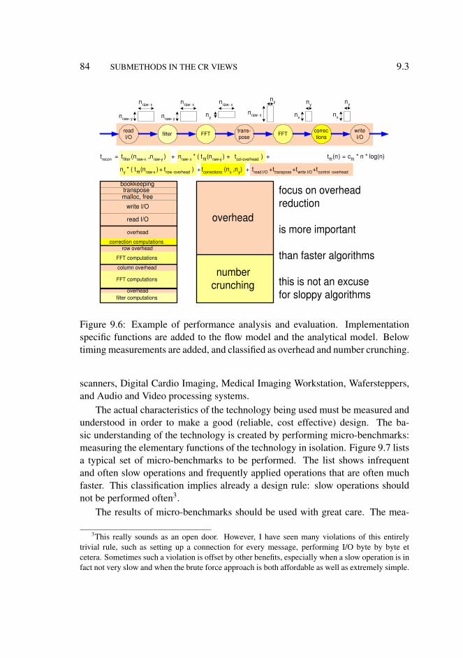
84 SUBMETHODS IN THE CR VIEWS 9.3
overhead
t recon = n raw- x * ( t fft (n raw-y )
n y * ( t fft (n raw-x )
t filter ( n raw-x ,n raw-y ) + +
+
t fft (n ) = c fft * n * log(n)
filter FFT FFT correc tions
t col-overhead
t corrections ( n x ,n y ) t row -overhead +t control -overhead +
) +
) +
n raw- x
n raw- y
n raw- x
n raw- y
n raw- x
n y
FFT computations
column overhead
FFT computations
row overhead correction computations
overhead filter computations
read I/O
write I/O malloc, free transpose
bookkeeping
number crunching
overhead
focus on overhead reduction
is more important
than faster algorithms
this is not an excuse for sloppy algorithms
read I/O
write I/O
trans- pose
n raw- x
n y
n x
n y
n x
n y
t read I/O +t write I/O +t transpose
Figure 9.6: Example of performance analysis and evaluation. Implementationspecific functions are added to the flow model and the analytical model. Belowtiming measurements are added, and classified as overhead and number crunching.
scanners, Digital Cardio Imaging, Medical Imaging Workstation, Wafersteppers,and Audio and Video processing systems.
The actual characteristics of the technology being used must be measured andunderstood in order to make a good (reliable, cost effective) design. The ba-sic understanding of the technology is created by performing micro-benchmarks:measuring the elementary functions of the technology in isolation. Figure 9.7 listsa typical set of micro-benchmarks to be performed. The list shows infrequentand often slow operations and frequently applied operations that are often muchfaster. This classification implies already a design rule: slow operations shouldnot be performed often3.
The results of micro-benchmarks should be used with great care. The mea-
3This really sounds as an open door. However, I have seen many violations of this entirelytrivial rule, such as setting up a connection for every message, performing I/O byte by byte etcetera. Sometimes such a violation is offset by other benefits, especially when a slow operation is infact not very slow and when the brute force approach is both affordable as well as extremely simple.
9.3 QUALITY DESIGN SUBMETHODS 85
object creation object destruction method invocation
component creation component destruction
open connection close connection
method invocation same scope other context
start session finish session
perform transaction query
transfer data
function call loop overhead basic operations (add, mul, load, store)
infrequent operations, often time-intensive
often repeated operations
database
network, I/O
high level construction
low level construction
basic programming
memory allocation memory free
task, thread creation OS task switch interrupt response
HW cache flush low level data transfer
power up, power down boot
Figure 9.7: Typical micro-benchmarks for timing aspects
surements show the performance in totally unrealistic circumstances, in otherwords it is the best case performance. This best case performance is a good base-line to understand performance, but when using the numbers the real life interfer-ence (cache disturbance for instance) should be taken into account. Sometimesadditional measurements are needed at a slightly higher level to calibrate the per-formance estimates.
The standard work about performance issues in computer architectures is thebook by Hennesey and Patterson [30]. Here modelling and measurement methodscan be found that can serve as inspiration for performance analysis of embeddedsystems.
9.3.2 Budgets
The implementation can be guided by making budgets for the most importantresource constraints, such as memory size, response time, or positioning accuracy.The budget serves multiple purposes:
• to make the design explicit• to provide a baseline to take decisions• to specify the requirements for the detailed designs• to have guidance during integration

86 SUBMETHODS IN THE CR VIEWS 9.3
• to provide a baseline for verification• to manage the design margins explicitly
The simplification of the design into budgets introduces design constraints.Simple budgets are entirely static. If such a simplification is too constraining orcostly then a dynamic budget can be made. A dynamic budget uses situationaldetermined data to describe the budget in that situation. The architect must ensurethe manageability of the budgets. A good budget has tens of quantities described.The danger of having a more detailed budget is the loss of overview.
1B model the performance s tarting with old systems
1A measure old systems
1C determine requirements for new system
2 make a design for the new system
3 make a budget for the new system:
4 measure prototypes and new system
flow model and analytical model
micro-benchmarks, aggregated functions, applications
response time or throughput
explore design space, estimate and simulate
step example
models provide the structure measurements and estimates provide initial numbers
specification provides bottom line
micro-benchmarks, aggregated functions, applications profiles, traces
5 Iterate steps 1B to 4
Figure 9.8: Budget-based design flow
Figure 9.8 shows a budget-based design flow. The starting point of a budgetis a model of the system, from the conceptual view. An existing system is usedto get a first guidance to fill the budget. In general the budget of a new system isequal to the budget of the old system, with a number of explicit improvements.The improvements must be substantiated with design estimates and simulationsof the new design. Of course the new budget must fulfill the specification of thenew system, sufficient improvements must be designed to achieve the requiredimprovement.
Early measurements in the integration are required to obtain feedback oncethe budget has been made. This feedback will result in design changes and couldeven result in specification changes.
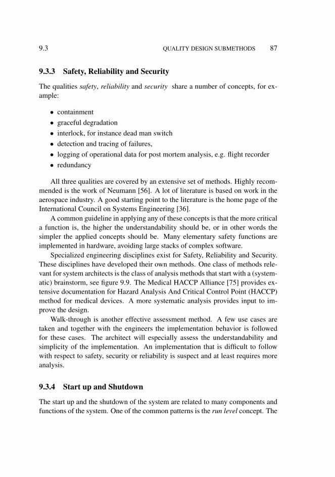
9.3 QUALITY DESIGN SUBMETHODS 87
9.3.3 Safety, Reliability and Security
The qualities safety, reliability and security share a number of concepts, for ex-ample:
• containment• graceful degradation• interlock, for instance dead man switch• detection and tracing of failures,• logging of operational data for post mortem analysis, e.g. flight recorder• redundancy
All three qualities are covered by an extensive set of methods. Highly recom-mended is the work of Neumann [56]. A lot of literature is based on work in theaerospace industry. A good starting point to the literature is the home page of theInternational Council on Systems Engineering [36].
A common guideline in applying any of these concepts is that the more criticala function is, the higher the understandability should be, or in other words thesimpler the applied concepts should be. Many elementary safety functions areimplemented in hardware, avoiding large stacks of complex software.
Specialized engineering disciplines exist for Safety, Reliability and Security.These disciplines have developed their own methods. One class of methods rele-vant for system architects is the class of analysis methods that start with a (system-atic) brainstorm, see figure 9.9. The Medical HACCP Alliance [75] provides ex-tensive documentation for Hazard Analysis And Critical Control Point (HACCP)method for medical devices. A more systematic analysis provides input to im-prove the design.
Walk-through is another effective assessment method. A few use cases aretaken and together with the engineers the implementation behavior is followedfor these cases. The architect will especially assess the understandability andsimplicity of the implementation. An implementation that is difficult to followwith respect to safety, security or reliability is suspect and at least requires moreanalysis.
9.3.4 Start up and Shutdown
The start up and the shutdown of the system are related to many components andfunctions of the system. One of the common patterns is the run level concept. The
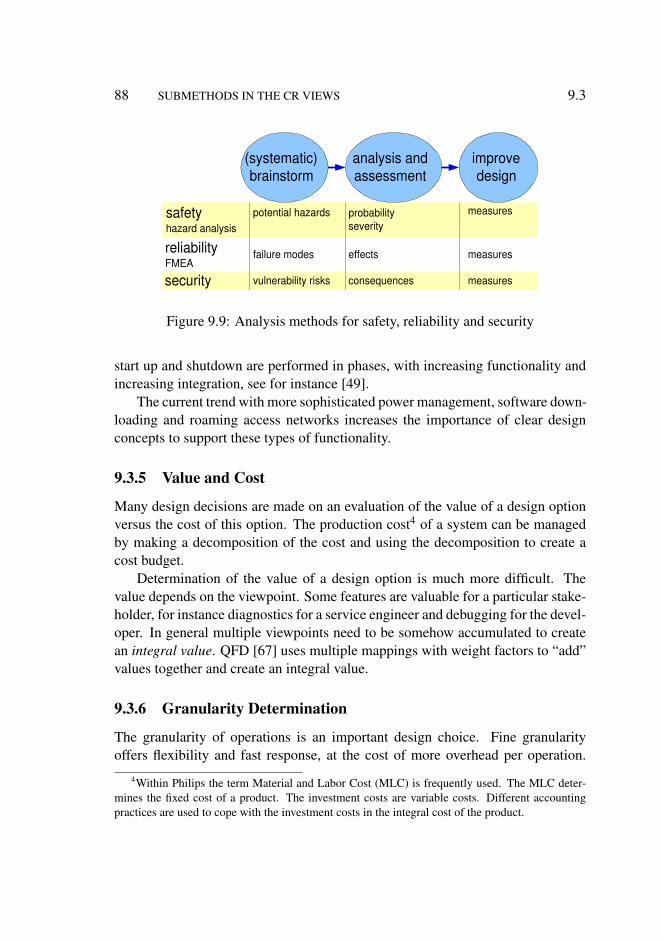
88 SUBMETHODS IN THE CR VIEWS 9.3
potential hazards safety hazard analysis
reliability FMEA
failure modes
security vulnerability risks
probability severity
effects
consequences
measures
measures
measures
analysis and assessment
(systematic) brainstorm
improve design
Figure 9.9: Analysis methods for safety, reliability and security
start up and shutdown are performed in phases, with increasing functionality andincreasing integration, see for instance [49].
The current trend with more sophisticated power management, software down-loading and roaming access networks increases the importance of clear designconcepts to support these types of functionality.
9.3.5 Value and Cost
Many design decisions are made on an evaluation of the value of a design optionversus the cost of this option. The production cost4 of a system can be managedby making a decomposition of the cost and using the decomposition to create acost budget.
Determination of the value of a design option is much more difficult. Thevalue depends on the viewpoint. Some features are valuable for a particular stake-holder, for instance diagnostics for a service engineer and debugging for the devel-oper. In general multiple viewpoints need to be somehow accumulated to createan integral value. QFD [67] uses multiple mappings with weight factors to “add”values together and create an integral value.
9.3.6 Granularity Determination
The granularity of operations is an important design choice. Fine granularityoffers flexibility and fast response, at the cost of more overhead per operation.
4Within Philips the term Material and Labor Cost (MLC) is frequently used. The MLC deter-mines the fixed cost of a product. The investment costs are variable costs. Different accountingpractices are used to cope with the investment costs in the integral cost of the product.

9.4 PROJECT MANAGEMENT SUPPORT 89
Coarse granularity creates less overhead, at the cost of less flexibility and longerlatencies. The determination of the granularity is an optimization problem thatcan be solved by applying optimization techniques from the operational research,see for an introduction [8].
Examples of operations where the unit size of operation has to be chosenare: buffering, synchronization, processing and input/output. In the case of videoprocessing examples of operation sizes are: pixel, line and frame. In real videoprocessing systems at this moment the unit size is typical a quarter of a videoframe. The latency of the video chain is critical for two reasons: the time differ-ence between audio and video must be small (lip-synchronization) and zappingmust be fast. Smaller unit sizes create too much overhead, larger unit sizes createtoo much latency.
9.4 Project Management Support
The architect supports the project leader. Typical contributions of the architect arean initial work breakdown and an integration plan. Many more project manage-ment submethods exist, see for instance [28], but most of them are less relevantfor the system architect.
A work breakdown is in fact again another decomposition, with a more orga-nizational point of view [28]. The work in the different work packages should becohesive internally, and should have low coupling with other work packages.
Figure 9.10 shows an example of a work breakdown. The entire project isbroken down in a hierarchical fashion: project, segment, work package. In thisexample color coding is applied to show the technology involved and to showdevelopment work or purchasing work. Both types of work require domain knowhow, but different skills to do the job.
Schedules, work breakdown and many technical decompositions are heavilyinfluenced by the integration plan. Integration is the effort of combining the com-ponents into a (sub)system, and to get the integrated (sub) system to work in theintended way. During the integration many specification and design inconsis-tencies, oversights, misunderstandings and mistakes are detected, analyzed andsolved. Integration typically costs a lot of time and effort. The risk in a project isthat the integration takes too much time and effort. Sufficient and regular attentionfor the integration viewpoint makes the risk better manageable.
Figure 9.11 shows an example of an integration plan. The systems that areused for the actual integration, the integration vehicles, are the limiting resource
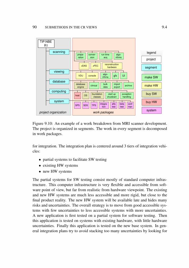
90 SUBMETHODS IN THE CR VIEWS 9.4
work packages project organization
TIP:NBE R1
x DAS reconstruction hardware
viewing
database
scanning
x FEC
run time acq
prepa- ration
conver- sion
algo- rithms
UI gfx algo- rithms VDU console
import export archive bulk
data clinical database engine
computing
system
host OS foundation classes
start up shutdown
exception handling
integra- tion SPS SDS TPS alfa
test beta test
conf man
make SW
make HW
buy SW
buy HW
system
segment
project
legend
Figure 9.10: An example of a work breakdown from MRI scanner development.The project is organized in segments. The work in every segment is decomposedin work packages.
for integration. The integration plan is centered around 3 tiers of integration vehi-cles:
• partial systems to facilitate SW testing• existing HW systems• new HW systems
The partial systems for SW testing consist mostly of standard computer infras-tructure. This computer infrastructure is very flexible and accessible from soft-ware point of view, but far from realistic from hardware viewpoint. The existingand new HW systems are much less accessible and more rigid, but close to thefinal product reality. The new HW system will be available late and hides manyrisks and uncertainties. The overall strategy is to move from good accessible sys-tems with few uncertainties to less accessible systems with more uncertainties.A new application is first tested on a partial system for software testing. Thenthis application is tested on systems with existing hardware, with little hardwareuncertainties. Finally this application is tested on the new base system. In gen-eral integration plans try to avoid stacking too many uncertainties by looking for
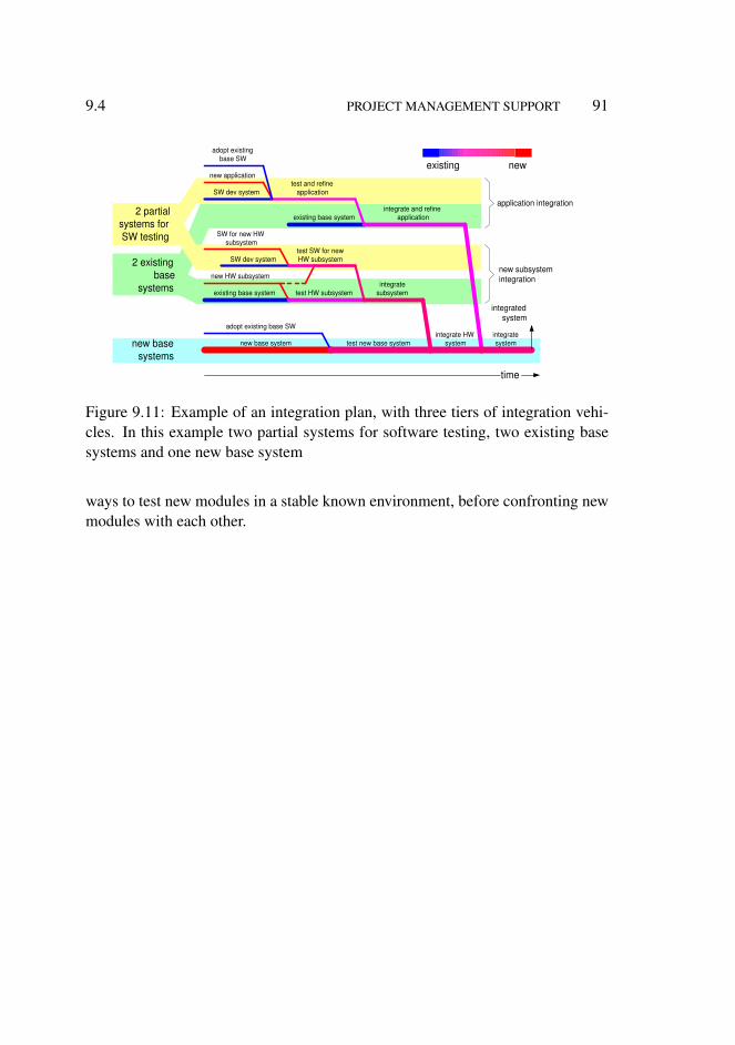
9.4 PROJECT MANAGEMENT SUPPORT 91
existing base system
new HW subsystem
SW dev system
test HW subsystem
test SW for new HW subsystem
new application
existing base system
integrate subsystem
SW dev system test and refine
application
integrate and refine application
adopt existing base SW
new base system test new base system integrate HW
system integrate system
SW for new HW subsystem
adopt existing base SW
existing new
2 partial systems for SW testing
2 existing base
systems
new base systems
time
integrated system
application integration
new subsystem integration
Figure 9.11: Example of an integration plan, with three tiers of integration vehi-cles. In this example two partial systems for software testing, two existing basesystems and one new base system
ways to test new modules in a stable known environment, before confronting newmodules with each other.

92 SUBMETHODS IN THE CR VIEWS 9.5
9.5 Overview of the Submethods in the CR views
Figure 9.12 shows an overview of the submethods that are discussed in this chap-ter. These submethods are positioned in the Conceptual View and the RealizationView. This positioning is not a black and white proposition, many submethods ad-dress aspects from multiple views. However, the positioning based on the essenceof the submethod helps to select the proper submethod.
C onceptual R ealization
construction decomposition functional decomposition designing with multiple decompositions execution architecture internal interfaces performance start up shutdown integration plan work breakdown safety reliability security
budget benchmarking performance analysis value and cost safety analysis reliability analysis security analysis granularity determination
Figure 9.12: Overview of the submethods discussed in this chapter, positioned inthe CR views
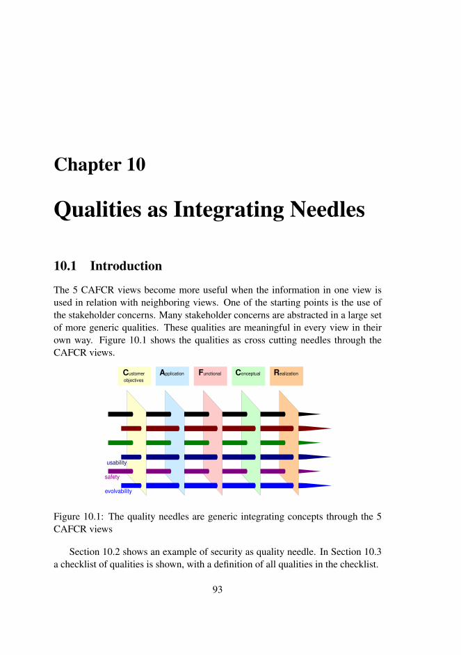
Chapter 10
Qualities as Integrating Needles
10.1 Introduction
The 5 CAFCR views become more useful when the information in one view isused in relation with neighboring views. One of the starting points is the use ofthe stakeholder concerns. Many stakeholder concerns are abstracted in a large setof more generic qualities. These qualities are meaningful in every view in theirown way. Figure 10.1 shows the qualities as cross cutting needles through theCAFCR views.
A pplication C ustomer objectives
F unctional C onceptual R ealization
safety
evolvability
usability
Figure 10.1: The quality needles are generic integrating concepts through the 5CAFCR views
Section 10.2 shows an example of security as quality needle. In Section 10.3a checklist of qualities is shown, with a definition of all qualities in the checklist.
93
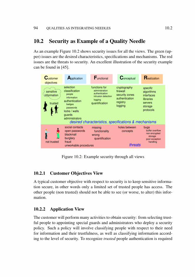
94 QUALITIES AS INTEGRATING NEEDLES 10.2
10.2 Security as Example of a Quality Needle
As an example Figure 10.2 shows security issues for all the views. The green (up-per) issues are the desired characteristics, specifications and mechanisms. The redissues are the threats to security. An excellent illustration of the security examplecan be found in [45].
A pplication C ustomer objectives
F unctional C onceptual R ealization
sensitive information
trusted
not trusted
selection classification
people information
authentication badges passwords
locks / walls guards administrators
social contacts open passwords blackmail burglary fraud unworkable procedures
cryptography firewall security zones authentication registry logging
holes between concepts
functions for administration authentication intrusion detection logging
quantification
bugs buffer overflow non encrypted
storage poor exception
handling
missing functionality
wrong quantification
specific algorithms interfaces libraries servers storage protocols
desired characteristics, specifications & mechanisms
threats
Figure 10.2: Example security through all views
10.2.1 Customer Objectives View
A typical customer objective with respect to security is to keep sensitive informa-tion secure, in other words only a limited set of trusted people has access. Theother people (non trusted) should not be able to see (or worse, to alter) this infor-mation.
10.2.2 Application View
The customer will perform many activities to obtain security: from selecting trust-ful people to appointing special guards and administrators who deploy a securitypolicy. Such a policy will involve classifying people with respect to their needfor information and their trustfulness, as well as classifying information accord-ing to the level of security. To recognize trusted people authentication is required
10.2 SECURITY AS EXAMPLE OF A QUALITY NEEDLE 95
by means of badges, passwords and in the future additional biometrics. Physicalsecurity by means of buildings, gates, locks, et cetera is also part of the securitypolicy.
The security is threatened in many ways, from burglary to fraud, but also fromsimple issues like people forgetting their password and writing it on a yellowsticker. Social contacts of trusted people can unwillingly expose sensitive infor-mation, for instance when two managers are discussing business in a businesslounge, while the competition is listening at the next table.
Unworkable procedures are a serious threat to security. For instance the forcedchange of passwords every month, resulting in many people writing down thepassword.
An interesting article is [15]. It shows how secret security procedures, inthis case for passenger screening at airports, is vulnerable. It describes a methodfor terrorists how to reverse engineer the procedures empirically, which turns theeffectiveness of the system from valuable to dangerous.
10.2.3 Functional View
The system under consideration will have to fit in the customer’s security. Func-tions for authentication and administration are required. The performance of thesystem needs to be expressed explicitly. For instance the required confidence levelof encryption and the speed of authentication have to be specified.
Security threats are usually caused by missing functionality or wrong quan-tification. This threat will surface in the actual use, where the users will find workarounds that compromise the security.
10.2.4 Conceptual View
Many technological concepts have been invented to make systems secure, for ex-ample cryptography, firewalls, security zones, authentication, registry, and log-ging. Every concept covers a limited set of aspects of security. For instancecryptography makes stored or transmitted data non-interpretable for non-trustedpeople.
Problems in the conceptual view are usually due to the non-ideal combinationof concepts. For instance cryptography requires keys. Authentication is used toaccess and validate keys. The interface between cryptography and authenticationis a risky issue. Another risky issue is the transfer of keys. All interfaces betweenthe concepts are suspicious areas, where poor design easily threatens the security.
96 QUALITIES AS INTEGRATING NEEDLES 10.3
10.2.5 Realization View
The concepts are realized in hardware and software with specific mechanisms,such as encryption algorithms and tamper free interfaces. These mechanisms canbe implemented in libraries, running at a distributed computer infrastructure. Ev-ery specific hardware and software element involved in the security concepts initself must be secure, in order to have a secure system.
A secure realization is far from trivial. Nearly all systems have bugs. Theencryption algorithm may be applicable, but if the library implementation is poorthen the overall security is still poor. Well known security related bugs are bufferoverflow bugs, that are exploited by hackers to gain access. Another example isstorage of very critical security data, such as passwords and encryption keys, innon encrypted form. In general exception handling is a source of security threatsin security.
10.2.6 Conclusion
Security is a quality that is heavily determined by the customer’s way of working(application view). To enable a security policy of the customer a well-designedand well-implemented system is required with security functionality fitting in thispolicy.
In practice the security policy of customers is a large source of problems.Heavy security features in the system will never solve such a shortcoming. An-other common source of security problems is poor design and implementation,causing a fair policy to be corrupted by the non-secure system.
Note that a very much simplified description of security has been presented,with the main purpose of illustration. A real security description will be moreextensive than described here.
10.3 Qualities Checklist
Figure 10.3 shows a large set of qualities that can be used as a checklist for ar-chitecting. This set is classified to ease the access to the list. The qualities arenot independent nor orthogonal, so every classification is at its best a means not agoal.
The following sections describe the different qualities briefly, in the functionalview. Note that every quality can in general be described in each of the views.For instance, if the system is a head end system for a cable operator, then the

10.3 QUALITIES CHECKLIST 97
usability attractiveness responsiveness image quality wearability storability transportability
usable
safety security reliability robustness integrity availability
dependable
throughput or productivity
effective
serviceability configurability installability
serviceable
liability testability traceability standards compliance
liable
ecological footprint contamination noise disposability
ecological
reproducibility predictability
consistent
efficient resource utilization cost of ownership
cost price power consumption consumption rate
(water, air, chemicals, et cetera)
size, weight accuracy
down to earth attributes
manufacturability logistics flexibility lead time
logistics friendly
evolvability portability upgradeability extendibility maintainability
future proof
interoperable connectivity 3 rd party extendible
Figure 10.3: Checklist of qualities
useability of the (head end) system describes in the functional view the useabilityof the system itself, while in the customer objectives view the useability deals withthe cable operator services.
The descriptions below are not intended to be the definition. Rather the list isintended to be used as a checklist, i.e. as a means to get a more all round view onthe architecture.
10.3.1 Usable
useability The useability is a measure of usefulness and ease of use of a system.
attractiveness The appeal or attractiveness of the system.
responsiveness The speed of responding to inputs from outside.
image quality The quality of images (resolution, contrast, deformation, et cetera).This can be more generally used for output quality, so also sound quality forinstance.
wearability The ease of wearing the system, or carrying the system around.
storability The ease of storing the system.
98 QUALITIES AS INTEGRATING NEEDLES 10.3
transportability The ease of transporting the system.
10.3.2 Dependable
safety The safety of the system. Note that this applies to all the stakeholders, forinstance safety of the patient, operator, service employee, et cetera. Somepeople include the safety of the machine itself in this category. In my viewthis belongs to system reliability and robustness.
security The level of protection of the information in the system against un-wanted access to the system.
reliability The probability that the systems operates reliable; the probability thatthe system is not broken and the software is not crashed. Here again the non-orthogonality of qualities is clear: an unreliable X-ray system is a safety riskwhen deployed for interventional surgery.
robustness The capability of the system to function in any (unforeseen) circum-stances, including being foolproof for non-educated users.
integrity Does the system yield the right outputs.
availability The availability of the system, often expressed in terms of (sched-uled) uptime and the chance of unwanted downtime.
10.3.3 Effective
throughput or productivity The integral productivity level of the system. Oftendefined for a few use cases. Integral means here including aspects likestart up shutdown, preventive maintenance, replacement of consumables etcetera. A bad attitude is to only specify the best case throughput, where allcircumstances are ideal and even simple start up effects are ignored.
10.3.4 Interoperable
3rd party extendable How open is the system for 3rd party extensions? PCs areextremely open; many embedded systems are not extendable at all.
connectivity What other systems can be connected to the system and what appli-cations are possible when connected?

10.3 QUALITIES CHECKLIST 99
10.3.5 Liable
liability The liability aspects with respect to the system; who is responsible forwhat, what are the legal liabilities, is the liability limited to an acceptablelevel?
testability The level of verifiability of the system, does the system perform asagreed upon?
traceability Is the operation of the system traceable? Traceability is required fordetermining liability aspects, but also for post mortem problem analysis.
standards compliance Large parts of the specification are defined in terms ofcompliance to standards.
10.3.6 Efficient
resource utilization The typical load of the system resources. Often specifiedfor the same use cases as used for the productivity specification.
cost of ownership The cost of ownership is an integral estimate of all costs ofowning and operating the system, including financing, personnel, mainte-nance, and consumables. Often only the sales price is taken as efficiencymeasure. This results in a suboptimal solution that minimize only the ma-terial cost.
10.3.7 Consistent
reproduceability Most systems are used highly repetitive. If the same operationis repeated over and over, the same result is expected all the time within thespecified accuracy.
predictability The outcome of the system should be understandable for its users.Normally this means that the outcome should be predictable.
10.3.8 Serviceable
serviceability The ease of servicing the system: indication of consumable status,diagnostic capabilities in case of problems, accessibility of system internals,compatibility of replaceable units, et cetera.

100 QUALITIES AS INTEGRATING NEEDLES 10.3
configurability The ease of configuring (and maintaining, updating the configu-ration) the system
installability The ease of installing the system; for example the time, space andskills needed for installing.
10.3.9 Future Proof
evolvability The capability to change in (small) steps to adapt to new changingcircumstances.
portability To be able to change the underlying platform, for instance from Win-dows NT to Linux, or from Windows 98SE to Windows XP.
upgradeability The capability of upgrading the entire or part of the system withimproved features.
extendability The capability to add options or new features.
maintainability The capability of maintaining the well-being of the system, alsounder changing circumstances, such as end-of-life of parts or consumables,or new safety or security regulations.
10.3.10 Logistics Friendly
manufacturability The ease of manufacturing the system; for example time,space and skills needed for manufacturing.
logistics flexibility The capability to quickly adapt the logistics flow, for instanceby fast ramp up (or down) supplier agreements, short lead times, low inte-gration effort and second suppliers.
lead time The time between ordering the system and the actual delivery.
10.3.11 Ecological
ecological footprint The integral ecological load of the system, expressed in “orig-inal” ecological costs. This means that if electricity is used, the generationof electricity (and its inefficiency) is included in the footprint.
contamination The amount of contamination produced by the system

10.4 SUMMARY 101
noise The (acoustical) noise produced by the system
disposability The way to get the system disposed, for instance the ability to de-compose the system and to recycle the materials.
10.3.12 Down to Earth Attributes
These attributes (as the name indicates) are so trivial that no further description isgiven.
cost price
power consumption
consumption rate (water, air, chemicals, et cetera)
size, weight
accuracy
10.4 Summary
The qualities of a system can be generalized to the other CAFCR views. This gen-eralization helps to understand the relationships between the views. Classificationof the qualities is the basis for a checklist of qualities. This checklist is a toolfor the architect: it helps the architect in determining the relevant qualities for thesystem to be created.

102 QUALITIES AS INTEGRATING NEEDLES 10.4
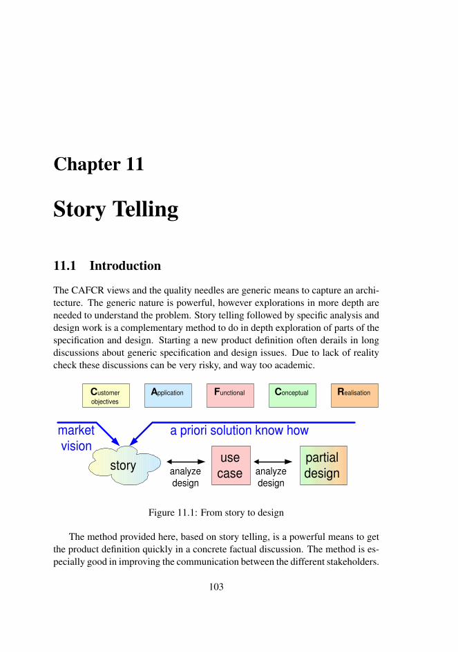
Chapter 11
Story Telling
11.1 Introduction
The CAFCR views and the quality needles are generic means to capture an archi-tecture. The generic nature is powerful, however explorations in more depth areneeded to understand the problem. Story telling followed by specific analysis anddesign work is a complementary method to do in depth exploration of parts of thespecification and design. Starting a new product definition often derails in longdiscussions about generic specification and design issues. Due to lack of realitycheck these discussions can be very risky, and way too academic.
story use case analyze
design
partial design analyze
design
a priori solution know how market vision
C ustomer objectives
A pplication F unctional C onceptual R ealisation
Figure 11.1: From story to design
The method provided here, based on story telling, is a powerful means to getthe product definition quickly in a concrete factual discussion. The method is es-pecially good in improving the communication between the different stakeholders.
103
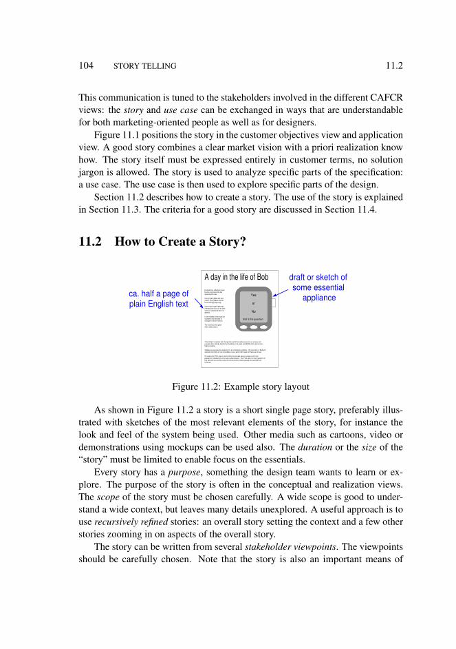
104 STORY TELLING 11.2
This communication is tuned to the stakeholders involved in the different CAFCRviews: the story and use case can be exchanged in ways that are understandablefor both marketing-oriented people as well as for designers.
Figure 11.1 positions the story in the customer objectives view and applicationview. A good story combines a clear market vision with a priori realization knowhow. The story itself must be expressed entirely in customer terms, no solutionjargon is allowed. The story is used to analyze specific parts of the specification:a use case. The use case is then used to explore specific parts of the design.
Section 11.2 describes how to create a story. The use of the story is explainedin Section 11.3. The criteria for a good story are discussed in Section 11.4.
11.2 How to Create a Story?
A day in the life of Bob bla blah bla, rabarber music bla bla composer bla bla qwwwety30 zeps.
nja nja njet njippie est quo vadis? Pjotr jaleski bla bla bla brree fgfg gsg hgrg
mjmm bas engel heeft een interressant excuus, lex stelt voor om vanavond door te werken.
In the middle of the night he is awake and decides to change the world forever.
The next hour the great event takes place:
This brilliant invention will change the world foreverbecause it is so unique and valuable that nobody beliefs the feasibility. It is great and WOW at the same time, highly exciting.
Vtables are seen as the soltution for an indirection problem. The invention of Bob will obsolete all of this in one incredibke move, which will make him famous forever.
He opens his PDA, logs in and enters his provate secure unqiue non trivial password, followed by a thorough authentication. The PDA asks for the fingerprint of this little left toe and to pronounce the word shit. After passing this test Bob can continue.
draft or sketch of some essential
appliance ca. half a page of plain English text
Yes
or
No
that is the question
Figure 11.2: Example story layout
As shown in Figure 11.2 a story is a short single page story, preferably illus-trated with sketches of the most relevant elements of the story, for instance thelook and feel of the system being used. Other media such as cartoons, video ordemonstrations using mockups can be used also. The duration or the size of the“story” must be limited to enable focus on the essentials.
Every story has a purpose, something the design team wants to learn or ex-plore. The purpose of the story is often in the conceptual and realization views.The scope of the story must be chosen carefully. A wide scope is good to under-stand a wide context, but leaves many details unexplored. A useful approach is touse recursively refined stories: an overall story setting the context and a few otherstories zooming in on aspects of the overall story.
The story can be written from several stakeholder viewpoints. The viewpointsshould be carefully chosen. Note that the story is also an important means of

11.4 HOW TO USE A STORY? 105
communication with customers, marketing managers and other domain experts.Some of the stakeholder viewpoints are especially useful in this communication.
11.3 How to Use a Story?
The story itself must be very accessible for all stakeholders. The story must beattractive and appealing to facilitate communication and discussion between thosestakeholders. The story is also used as input for a more systematic analysis of theproduct specification in the functional view. All functions, performance figuresand quality attributes are extracted from the story. The analysis results are used toexplore the design options.
Normally several iterations will take place between story, case and designexploration. During the first iteration many questions will be raised in the caseanalysis and design, which are caused by the story being insufficiently specific.This needs to be addressed by making the story more explicit. Care should betaken that the story stays in the Customers views and that the story is not extendedtoo much. The story should be sharpened, in other words made more explicit, toanswer the questions.
After a few iterations a clear integral overview and understanding emerges forthis very specific story. This insight is used as a starting point to create a morecomplete specification and design.
11.4 Criteria
Figure 11.3 shows the criteria for a good story. It is recommended to assess a storyagainst this checklist and either improve the story such that it meets all the criteriaor reject the story. Fulfillment of these criteria helps to obtain a useful story. Theset of five criteria is a necessary but not sufficient set of criteria. The value of astory can only be measured in retrospect by determining the contribution of thestory to the specification and design process.
Subsections 11.4.1 to 11.4.5 describe every criterion in more detail.
11.4.1 Accessible, Understandable
The main function of a story is to make the opportunity or problem communicablewith all the stakeholders. This means that the story must be accessible and under-standable for all stakeholders. The description or presentation should be such that
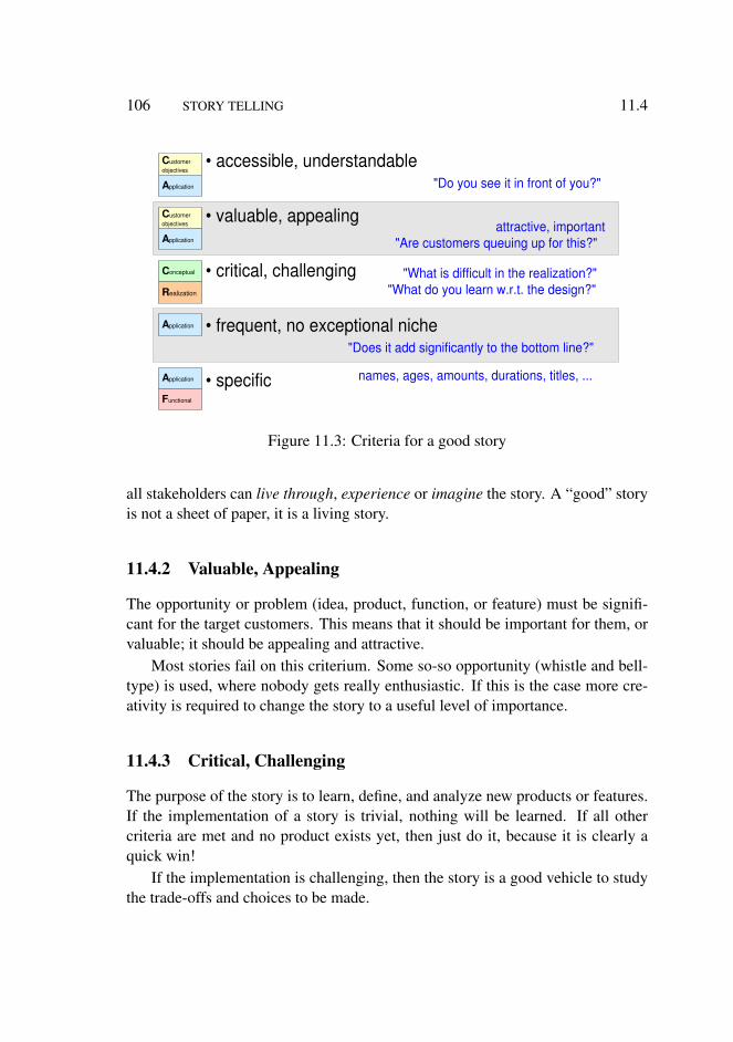
106 STORY TELLING 11.4
• accessible, understandable
• valuable, appealing
• critical, challenging
• frequent, no exceptional niche
• specific
"Do you see it in front of you?"
attractive, important "Are customers queuing up for this?"
"What is difficult in the realization?" "What do you learn w.r.t. the design?"
names, ages, amounts, durations, titles, ...
"Does it add significantly to the bottom line?"
C ustomer objectives
A pplication
F unctional
C onceptual
R ealization
C ustomer objectives
A pplication
A pplication
A pplication
Figure 11.3: Criteria for a good story
all stakeholders can live through, experience or imagine the story. A “good” storyis not a sheet of paper, it is a living story.
11.4.2 Valuable, Appealing
The opportunity or problem (idea, product, function, or feature) must be signifi-cant for the target customers. This means that it should be important for them, orvaluable; it should be appealing and attractive.
Most stories fail on this criterium. Some so-so opportunity (whistle and bell-type) is used, where nobody gets really enthusiastic. If this is the case more cre-ativity is required to change the story to a useful level of importance.
11.4.3 Critical, Challenging
The purpose of the story is to learn, define, and analyze new products or features.If the implementation of a story is trivial, nothing will be learned. If all othercriteria are met and no product exists yet, then just do it, because it is clearly aquick win!
If the implementation is challenging, then the story is a good vehicle to studythe trade-offs and choices to be made.
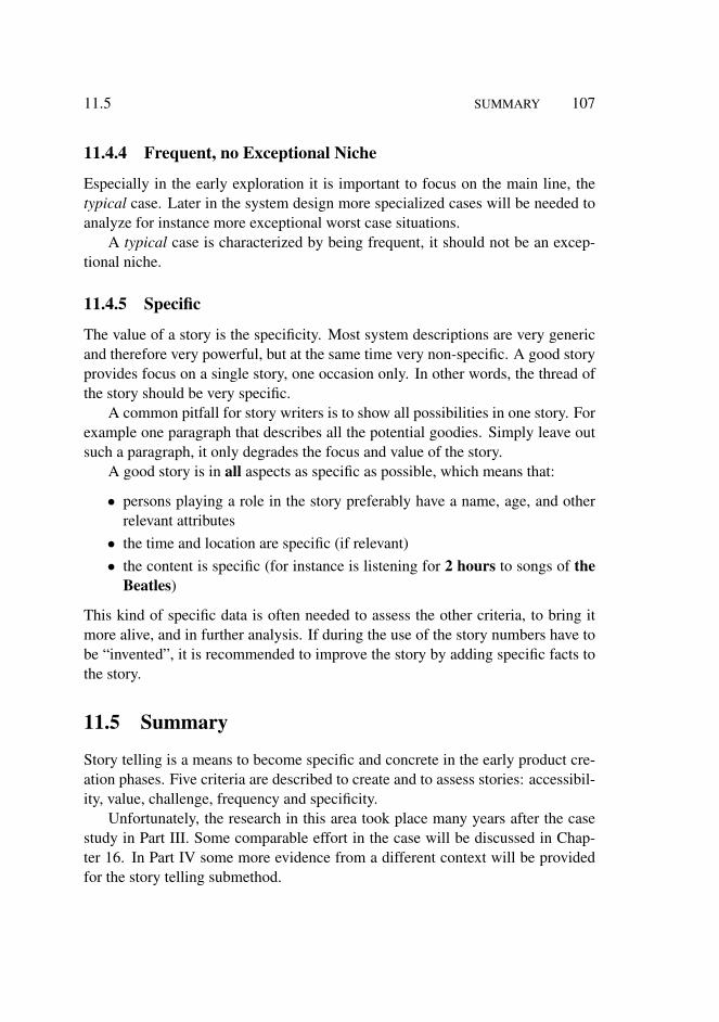
11.5 SUMMARY 107
11.4.4 Frequent, no Exceptional Niche
Especially in the early exploration it is important to focus on the main line, thetypical case. Later in the system design more specialized cases will be needed toanalyze for instance more exceptional worst case situations.
A typical case is characterized by being frequent, it should not be an excep-tional niche.
11.4.5 Specific
The value of a story is the specificity. Most system descriptions are very genericand therefore very powerful, but at the same time very non-specific. A good storyprovides focus on a single story, one occasion only. In other words, the thread ofthe story should be very specific.
A common pitfall for story writers is to show all possibilities in one story. Forexample one paragraph that describes all the potential goodies. Simply leave outsuch a paragraph, it only degrades the focus and value of the story.
A good story is in all aspects as specific as possible, which means that:
• persons playing a role in the story preferably have a name, age, and otherrelevant attributes
• the time and location are specific (if relevant)• the content is specific (for instance is listening for 2 hours to songs of the
Beatles)
This kind of specific data is often needed to assess the other criteria, to bring itmore alive, and in further analysis. If during the use of the story numbers have tobe “invented”, it is recommended to improve the story by adding specific facts tothe story.
11.5 Summary
Story telling is a means to become specific and concrete in the early product cre-ation phases. Five criteria are described to create and to assess stories: accessibil-ity, value, challenge, frequency and specificity.
Unfortunately, the research in this area took place many years after the casestudy in Part III. Some comparable effort in the case will be discussed in Chap-ter 16. In Part IV some more evidence from a different context will be providedfor the story telling submethod.

108 STORY TELLING 11.5

Chapter 12
Threads of Reasoning
12.1 Introduction
The submethods provide generic means to cope with a limited part of the systemarchitecture. The CAFCR model and the qualities provide a framework to positionthese results. The story telling is a means to do analysis and design work on thebasis of concrete and specific facts. In this chapter a reasoning method is discussedto integrate all previous submethods. This reasoning method covers both the highlevel and the detailed views and covers the relation between multiple submethodsand multiple qualities. The method is based on the identification of the points oftension in the problem and potential solutions.
The reasoning approach is explained as a 5 step approach. Section 12.2 pro-vides an overview of the approach and gives a short introduction to each step. Sec-tion 12.3 describes the actual reasoning over multiple viewpoints: how to maintainfocus and overview in such a multi-dimensional space? How to communicate anddocument? Section 12.4 explains how the threads of reasoning fit in the completemethod.
12.2 Overview of Reasoning Approach
Fast exploration of the problem and solution space improves the quality of thespecification and design decisions, as explained in Chapter 7. It is essential torealize that such an exploration is highly concurrent, it is neither top-down, norbottom-up, see viewpoint hopping and decision making in Sections 7.2 and 7.8. Inpractice many designers find it difficult to make a start. In fact this does not have
109

110 THREADS OF REASONING 12.2
to be difficult: most starting points can be used, as long as the method is used witha sufficient open mind (that means that the starting point can be changed, when theteam discovers that more important specification or design decisions are needed).
2. create insight: + submethod in one of CAFCR views + qualities checklist
3. deepen insight via facts: + via tests, measurements, simulations + story telling
4. broaden insight via questions: + why + what + how
5. define and extend the thread: ? what is the most important / valuable ? what is the most critical / sensitive ! look for the conflicts and tension
1. select starting point: ! actual dominant need or problem
continuously
consolidate in simple models
communicate to stakeholders
refactor documentation
Figure 12.1: Overview of reasoning approach
Figure 12.1 shows an overview of the entire reasoning approach. Step 1 is toselect a starting point. After step 1 the iteration starts with step 2 create insight.Step 3 is deepening the insight and step 4 is broadening the insight with the ques-tions. The next iteration is prepared by step 5 refining or selecting the next needor problem.
During this iteration continuous effort is required to communicate with thestakeholders to keep them up to date, to consolidate in simple models that areused during analysis and discussions and to refactor the documentation to keep itup to date with the insights obtained.
12.2.1 Selecting a Starting Point
As stated earlier it is more important to get started with the iteration than to spenda lot of time trying to find the most ideal starting point. A very useful startingpoint is to take a need or problem that is very hot at the moment. If this issue
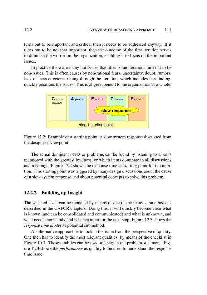
12.2 OVERVIEW OF REASONING APPROACH 111
turns out to be important and critical then it needs to be addressed anyway. If itturns out to be not that important, then the outcome of the first iteration servesto diminish the worries in the organization, enabling it to focus on the importantissues.
In practice there are many hot issues that after some iterations turn out to benon-issues. This is often causes by non-rational fears, uncertainty, doubt, rumors,lack of facts et cetera. Going through the iteration, which includes fact finding,quickly positions the issues. This is of great benefit to the organization as a whole.
step 1 starting point
C ustomer objectives
A pplication F unctional C onceptual R ealization
slow response
Figure 12.2: Example of a starting point: a slow system response discussed fromthe designer’s viewpoint
The actual dominant needs or problems can be found by listening to what ismentioned with the greatest loudness, or which items dominate in all discussionsand meetings. Figure 12.2 shows the response time as starting point for the itera-tion. This starting point was triggered by many design discussions about the causeof a slow system response and about potential concepts to solve this problem.
12.2.2 Building up Insight
The selected issue can be modeled by means of one of the many submethods asdescribed in the CAFCR chapters. Doing this, it will quickly become clear whatis known (and can be consolidated and communicated) and what is unknown, andwhat needs more study and is hence input for the next step. Figure 12.3 shows theresponse time model as potential submethod.
An alternative approach is to look at the issue from the perspective of quality.One then has to identify the most relevant qualities, by means of the checklist inFigure 10.3. These qualities can be used to sharpen the problem statement. Fig-ure 12.3 shows the performance as quality to be used to understand the responsetime issue.
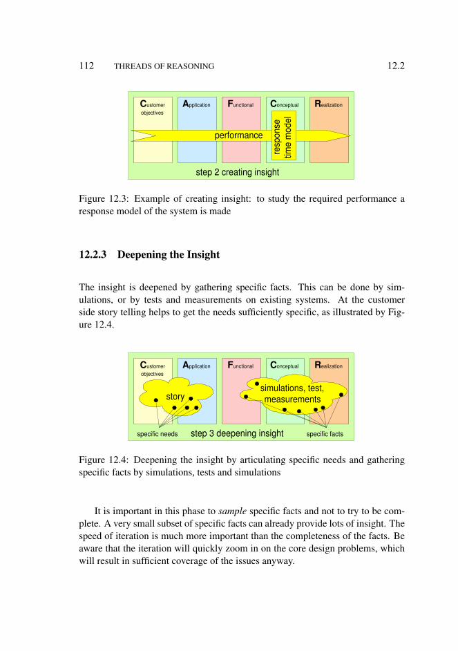
112 THREADS OF REASONING 12.2
step 2 creating insight
C ustomer objectives
A pplication F unctional C onceptual R ealization
performance
resp
onse
tim
e m
odel
Figure 12.3: Example of creating insight: to study the required performance aresponse model of the system is made
12.2.3 Deepening the Insight
The insight is deepened by gathering specific facts. This can be done by sim-ulations, or by tests and measurements on existing systems. At the customerside story telling helps to get the needs sufficiently specific, as illustrated by Fig-ure 12.4.
step 3 deepening insight
C ustomer objectives
A pplication F unctional C onceptual R ealization
story
specific needs
simulations, test, measurements
specific facts
Figure 12.4: Deepening the insight by articulating specific needs and gatheringspecific facts by simulations, tests and simulations
It is important in this phase to sample specific facts and not to try to be com-plete. A very small subset of specific facts can already provide lots of insight. Thespeed of iteration is much more important than the completeness of the facts. Beaware that the iteration will quickly zoom in on the core design problems, whichwill result in sufficient coverage of the issues anyway.

12.2 OVERVIEW OF REASONING APPROACH 113
12.2.4 Broadening the Insight
Needs and problems are never nicely isolated from the context. In many cases thereason why something is called a problem is because of the interaction betweenthe function and the context. The insight is broadened by relating the need orproblem to the other views in the CAFCR model. This can be achieved by the why,what and how questions as described in Section 7.7 and shown in Figure 12.5.
step 4 broadening insight
C ustomer objectives
A pplication F unctional C onceptual R ealization
why? what?
how? how? what?
why?
how?
why? w
hat
how
?
Figure 12.5: Broadening the insight by repeating why, what and how questions
The insight in the quality dimension can also be broadened by looking at theinteraction with related qualities: what happens with safety, when we increase theperformance?
12.2.5 Define and Extend the Thread
During the study and discussion of the needs and problems many new questionsand problems pop up. A single problem can trigger an avalanche of new prob-lems. Key in the approach is not to drown in this infinite ocean full of issues,by maintaining focus on important and critical issues. The most progress can bemade by identifying the specification and design decisions that seem to be themost conflicting, i.e. where the most tension exists between the issues.
The relevance of a problem is determined by the value or the importance ofthe problem for the customer. The relevance is also determined by how challeng-ing a problem is to solve. Problems that can be solved in a trivial way shouldimmediately be solved. The approach as described is useful for problems that re-quire some critical technical implementation. The implementation can be criticalbecause it is difficult to realize, or because the design is rather sensitive1 or rather
1for instance in MRI systems the radius of the gradient coil system and the cost price were relatedwith (rmagnet − rgradientcoil)
5. 1 cm more patient space would increase the cost dramatically,while at the same time patient space is crucial because of claustrophobia.

114 THREADS OF REASONING 12.3
vulnerable (for example, hard real-time systems with processor loads up to 70%).
C ustomer objectives
A pplication F unctional C onceptual R ealization
definition in terms of tension
image quality
performance
cost
algorithms
multi processor pipeline design
Figure 12.6: Example definition of the thread in terms of tension for a digital TV
Figure 12.6 shows the next crucial element to define the thread: identifica-tion the tension between needs and implementation options. The problem can beformulated in terms of this tension. A clearly articulated problem is half of thesolution.
The example in Figure 12.6 shows the tension between the customer objec-tives and the design options. The image quality objective requires good algorithmsthat require a lot of processing power. Insufficient processing power lowers thesystem performance. The processing power is achieved by a pipeline of multipleprocessors. The cost of the number crunching capacity easily exceeds the costtarget.
12.3 Reasoning
The reasoning by the architect is based on a combination of subjective intuitionand objective analysis. The intuition is used to determine the direction and toevaluate results. The analysis partially validates the direction and partially helpsthe architect to develop his intuition further.
The assessment of the solutions is done by means of criteria. An objectiveranking of the solutions can be made based on these criteria. The architect (andthe other stakeholders) have their own subjective ranking based on intuition. Bycomparing the objective and subjective rankings a better understanding is achievedof both problem and solutions. This is shown in Figure 12.7. The increased un-derstanding of the problem is used to improve the criteria. The increased under-standing of the problem and the solutions influences the intuition of the architect(for instance this type of function is more expensive than expected). The increased

12.3 REASONING 115
detect mismatch
architect intuition
objective criteria
objective ranking
intuitive ranking
solution
problem
improved solution understanding
improved problem understanding
improve criteria
adjust intuition
improve solution
solution solution
Figure 12.7: Reasoning as a feedback loop that combines intuition and analysis
understanding of the solution will trigger new solution(s).
C ustomer objectives
A pplication F unctional C onceptual R ealization
Figure 12.8: One thread of reasoning showing related issues. The line thicknessis an indication for the weight of the relation.
During the reasoning a network of related issues emerges, as shown in Fig-ure 12.8. Figure 12.8 visualizes the network as a graph, where a dot represents aspecification or a design decision and a line represents a relation. Such a relationcan be: is implemented by, is detailed by, is conflicting with, enables or supportset cetera. The thickness of the line indicates the weight of the relation (thin isweak, thick is strong).
This graph is a visualization of the thread of reasoning followed by an archi-tect. Crucial in such a thread is that it is sufficiently limited to maintain overview

116 THREADS OF REASONING 12.4
and to enable discussion and reasoning. A good thread of reasoning addressesrelevant problem(s), without drowning in the real world complexity.
C ustomer objectives
A pplication F unctional C onceptual R ealization
key drivers
cost
perfor- mance
response time
target CoO
store
zap
IQ
case IQ
spec
context
cost budget
time budget
pipeline design
functional model
processing library
micro benchmarks
Figure 12.9: Example of the documentation and communication for a digital TV.The thread is documented in a structured way, despite the chaotic creation path.This structure emerges after several iterations.
A continuous concern is to communicate with the stakeholders and to con-solidate the findings, for instance in documentation. Figure 12.9 shows the morestructured way to document and communicate these findings. The architect needsseveral iterations to recognize the structure in the seeming chaotic thread of rea-soning. This example discusses the thread that has been shown in Figure 12.6.This single thread of reasoning addresses three key drivers as shown in Figure 12.9:IQ (Image Quality), cost and performance. Most information in the thread of rea-soning addresses these key drivers, however some additional information emergestoo, such as the context of the digital TV at home, the functionality of the zap andstore functions and the internal functional models.
12.4 Outline of the complete method
The threads of reasoning are the integration means of the overall method. In thissection a short description is given how the threads of reasoning are are com-bined with the submethods, quality checklists and story telling to form a completemethod. The steps in the description refer to Figure 12.7. Note that this aspect isspeculative, because it has not been applied and therefore cannot be evaluated at

12.5 SUMMARY 117
this moment. Only an outline can be given now. A more detailed description ofthe method has to wait until further research is due.
The starting point (step 1) of a product creation is often a limited product spec-ification, belonging in the Functional view. The next step is to explore (step 2)the customer context (Customer Objectives and Application views) and to explorethe technical merits (Conceptual and Realization views). This exploration is usedto identify a first set of customer-side opportunities and to identify the biggesttechnical challenges. During the exploration the submethods and quality check-lists are used as a source of inspiration, for instance to determine the opportunityin the business model of the customer. Next (step 3) a story must be created thataddresses the most important and valuable opportunities and the biggest technicalchallenges. The story is used to derive a first use case and to do a more thoroughexploration (step 4) of the specification and the design. At this moment the firstthread of reasoning is already visible (step 5), connecting a coarse product speci-fication with customer opportunities and technical challenges. From this momentonwards the steps are repeated over and over, extending the thread of reasoningand creating one or two more threads of reasoning if needed. The submethods andthe qualities are used during these iterations as a toolbox to describe specific partsof this creation process.
12.5 Summary
The reasoning approach is a means to integrate the CAFCR views and the qualitiesto design a system that fits entirely in the customer needs. The threads of reason-ing approach is described by five steps. The result can be visualized as a graphof many related customer needs, specification issues and design issues. In thisgraph the core reasoning can be indicated around a limited set of key drivers orquality needs. In Chapter 17 the graph will be visualized for the Medical ImagingWorkstation case.

118 THREADS OF REASONING 12.5
Part III
Medical Imaging CaseDescription
Chapters in Part III:
13. Medical Imaging in Chronological Order
14. Medical Imaging Workstation: CAF Views
15. Medical Imaging Workstation: CR Views
16. Story Telling in Medical Imaging
17. Threads of Reasoning in the Medical Imaging Case
119


Chapter 13
Medical Imaging inChronological Order
13.1 Project Context
Philips Medical Systems is a very old company, dating back to 1896 when the firstX-ray tubes were manufactured. Many imaging modalities have been added to theportfolio later, such as Ultra Sound, Nuclear Medicaid, Computed Tomographyand Magnetic Resonance Imaging. Since the late seventies the management wasconcerned by the growing effort to develop the viewing functionality of thesesystems. Many attempts have been made to create a shared implementation of theviewing functionality, with failures and partial successes.
In 1987 a new attempt was started by composing a team, that had the char-ter to create a Common Viewing platform to be used in all the modalities. Thisteam had the vision that a well designed set of SW components running on stan-dard workstation hardware would be the solution. In the beginning of 1991 manycomponents had been built. For demonstration purposes a Basic Application wasdeveloped. The Basic Application makes all lower level functionality availablevia a rather technology-oriented graphical user interface. The case descriptionstarts at this moment, when the Basic Application is shown to stakeholders withinPhilips Medical Systems.
121

122 MEDICAL IMAGING IN CHRONOLOGICAL ORDER 13.3
13.2 Introduction
The context of the first release of Medical Imaging is shown in Section 13.1. Thechronological development of the first release of the medical imaging workstationis described in Section 13.3. Sections 13.4 and 13.5 zoom in on two specificproblems encountered during this period.
13.3 Development of Easyvision RF
The new marketing manager of the Common Viewing group was impressed bythe functionality and performance of the Basic Application. He thought that astand alone product derived from the Basic Application would create a businessopportunity. The derived product was called Easyvision, the first release of theproduct was called Easyvision R/F. This first release would serve the URF X-raymarket. The Common Viewing management team decided to create Easyvision RFin the beginning of 1991.
basic application toolboxes 100 kloc
interactive viewing
marketing opinion: "All the functionality is available, we only have to provide a clinical UI"
Easyvision RF integrated product 360 kloc
print server + communication + interactive viewing
1991 1993 1992
performance problems
IQ problems
Figure 13.1: Chronological overview of the development of the first release of theEasyvision
The enthusiasm of the marketing people for the Basic Application was basedon the wealth of functionality that was shown. It provided all necessary viewingfunctions and even more. Figure 13.1 shows the chronology, and the initial mar-keting opinion. Marketing also remarked: ”Normally we have to beg for morefunctionality, but now we have the luxury to throw out functionality”. The ad-dition of viewing software to the conventional modality products1 was difficult
1Modality products are products that use one imaging technique such as Ultra Sound, X-ray or
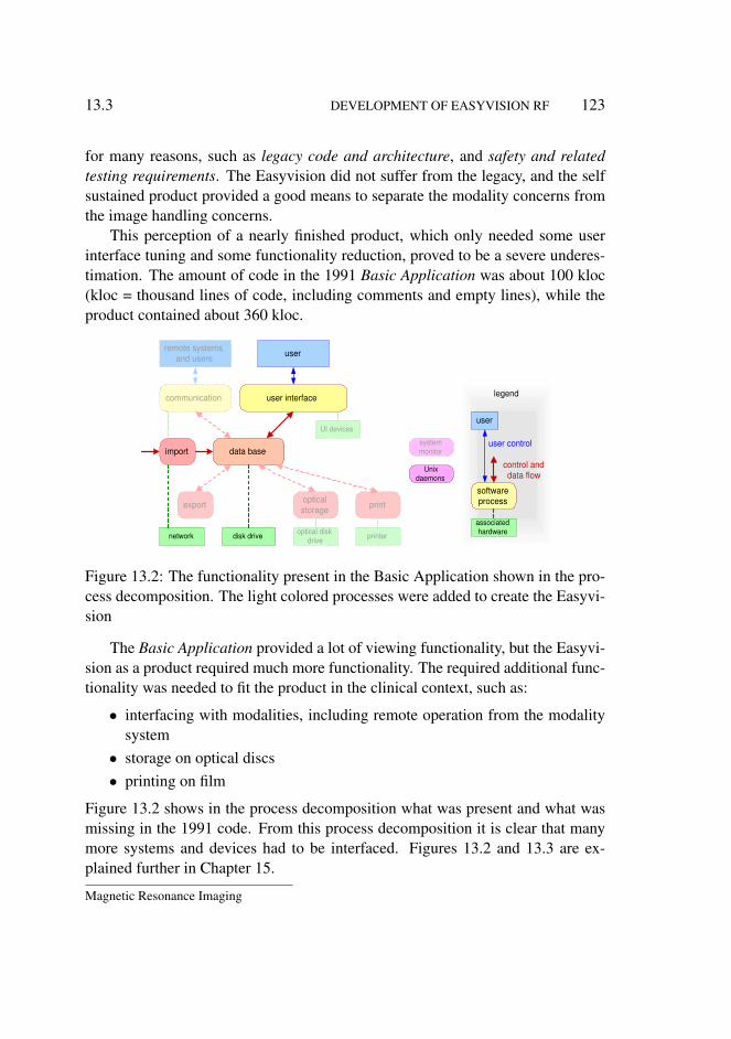
13.3 DEVELOPMENT OF EASYVISION RF 123
for many reasons, such as legacy code and architecture, and safety and relatedtesting requirements. The Easyvision did not suffer from the legacy, and the selfsustained product provided a good means to separate the modality concerns fromthe image handling concerns.
This perception of a nearly finished product, which only needed some userinterface tuning and some functionality reduction, proved to be a severe underes-timation. The amount of code in the 1991 Basic Application was about 100 kloc(kloc = thousand lines of code, including comments and empty lines), while theproduct contained about 360 kloc.
user interface communication
data base
export print optical storage
optical disk drive printer disk drive network
UI devices
system monitor
Unix daemons
software process
associated hardware
control and data flow
remote systems and users user
user
user control import
legend
Figure 13.2: The functionality present in the Basic Application shown in the pro-cess decomposition. The light colored processes were added to create the Easyvi-sion
The Basic Application provided a lot of viewing functionality, but the Easyvi-sion as a product required much more functionality. The required additional func-tionality was needed to fit the product in the clinical context, such as:
• interfacing with modalities, including remote operation from the modalitysystem
• storage on optical discs• printing on film
Figure 13.2 shows in the process decomposition what was present and what wasmissing in the 1991 code. From this process decomposition it is clear that manymore systems and devices had to be interfaced. Figures 13.2 and 13.3 are ex-plained further in Chapter 15.
Magnetic Resonance Imaging

124 MEDICAL IMAGING IN CHRONOLOGICAL ORDER 13.4
legend
DSI
3M RC
Desk, cabinets, cables, etc.
Standard Sun workstation DOR HC interf
RC interf
SunOS, SunView
NIX RC driver
HC driver
DOR driver
Spool HCU Store Image Gfx UI DB PMS- net in
PMS- net out
Medical Imaging R/F
Start up
Install
Config
SW keys
service
dev. tools Print Store View Cluster
operating system
hardware
application functions
user interface
connected system
SW infrastructure
toolbox
Figure 13.3: The functionality present in the Basic Application shown in the con-struction decomposition. The light colored components were added to create theEasyvision
Figure 13.3 also shows what was present and what was missing in the BasicApplication, but now in the construction decomposition. Here it becomes clearthat also the application-oriented functionality was missing. The Basic Applica-tion offered generic viewing functionality, exposing all functionality in a rathertechnical way to the user. The clinical RF user expects a very specific viewinginteraction, that is based on knowledge of the RF application domain.
The project phases from the conception of a new product to the introduction inthe market is characterized by many architectural decisions. Architecting methodsare valuable means in this period. Characteristic for an immature architectingprocess is that several crises occur in the integration. As shown in Figure 13.1both a performance and a (image quality related) safety crisis happened in thatperiod.
13.4 Performance Problem
The performance of the system at the end of 1991 was poor, below expectation.One of the causes was the extensive use of memory. Figure 13.4 shows the per-formance of the system as a function of the memory used. It is also indicates thata typically loaded system at that moment used about 200 MByte. Systems whichuse much more memory than the available physical memory decrease significantlyin performance due to the paging and swapping to get data from the slow disk to

13.4 PERFORMANCE PROBLEM 125
the fast physical memory and vice versa.
total measured memory usage pe
rform
ance
physical memory paging to disk
MB 64 200
code O S data bulk data fragmen-
tation
MB 0 memory usage
Figure 13.4: Memory usage half way R1
The analysis of additional measurements resulted in a decomposition of thememory used. The decomposition and the measurements are later used to allo-cate memory budgets. Figure 13.5 shows how the problem of poor performancewas tackled, which is explained in much more detail in Chapter 15. The largestgains were obtained by the use of shared libraries, and by implementing an anti-fragmentation strategy for bulk data. Smaller gains were obtained by tuning, andanalyzing the specific memory use more critical.
measured
code
OS
data
bulk data
fragmen- tation
budget
anti-fragmenting
budget based
awareness, measurement
DLLs
tuning
200 MB
74 MB
Figure 13.5: Solution of memory performance problem
Figure 13.6 shows the situation per process. Here the shared libraries are

126 MEDICAL IMAGING IN CHRONOLOGICAL ORDER 13.4
shown separate of the processes. The category other is the accumulation of anumber of small processes. This figure shows that every individual process didfit in the available amount of memory. A typical developer tests one process ata time. The developers did not experience a decreased performance caused bypaging, because the system is not paging if only one process is active. At thetime of integration, however, the processes are running on the same hardwareconcurrently and then the performance is suddenly very poor.
shar
ed li
brar
ies
UI
com
mun
icat
ion
serv
er
stor
age
serv
er
prin
t ser
ver
othe
r
UN
IX
10
20
30
0
budget per process (right column)
10
MByte
measured (left column)
data
co
de
20
Figure 13.6: Visualization per process
Many other causes of performance problems have been found. All of these areshown in the annotated overlay on the software process structure in Figure 13.7.
user interface communication
data base
export print optical storage
optical disk drive printer disk drive network
UI devices
remote systems and users user
data base granularity information model layering
process communication overhead active data granularity, update
graphics updates framebuffer access
I/O overhead
network I/O overhead
processing
file I/O overhead
Figure 13.7: Causes of performance problems, other than memory use
Many of the performance problems are related to overhead, for instance forI/O and communication. A crucial set of design choices is related to granularity:

13.5 SAFETY 127
a fine grain design causes a lot of overhead. Another related design choice is themechanism to be used: high level mechanisms introduce invisible overheads. Howaware should an application programmer be of the underlying design choices?
For example, accessing patient information might result in an implicit transac-tion and query on the database. Building a patient selection screen by repeatedlycalling such a function would cause tens to hundreds of transactions. With 25 msper transaction this would result in seconds of overhead only to obtain the rightinformation. The response becomes even worse if many layers of informationhave to be retrieved (patient, examination, study, series, image), resulting in evenworse response time.
The rendering to the screen poses another set of challenges. The original Ba-sic Application was built on Solaris 1, with the SunView windowing system. Thissystem was very performance efficient. The product moved away from SunView,which was declared to be obsolete by the vendor, to the X-windowing system.The application and the windowing are running in separate processes. As a con-sequence all screen updates cause process communication overhead, includingseveral copy operations of screen bitmaps. This problem was solved by imple-menting an integrated X-compatible screen manager running in the same processas the application, called Nix2.
Interactive graphics require a fast response. The original brute force methodto regenerate always the entire graphics object was too slow. The graphics im-plementation had to be redesigned, using damage area techniques to obtain therequired responsiveness.
13.5 Safety
The clinical image quality can only be assessed by clinical stakeholders. Clinicalstakeholders start to use the system, when the performance, functionality and re-liability of the system is at a reasonable level. This reasonable level is achievedafter a lot of integration effort has been spent. the consequence is that image qual-ity problems tend to be detected very late in the integration. Most image qualityproblems are not recognized by the technology-oriented designers. The technicalimage quality (resolution, brightness, contrast) is usually not the problem.
Figure 13.8 shows a typical image quality problem that popped up during theintegration phase. The pixel value x, corresponding to the amount of X-ray dosereceived in the detector, has to be transformed into a grey value f(x) that is used
2A Dutch play on words: niks means nothing
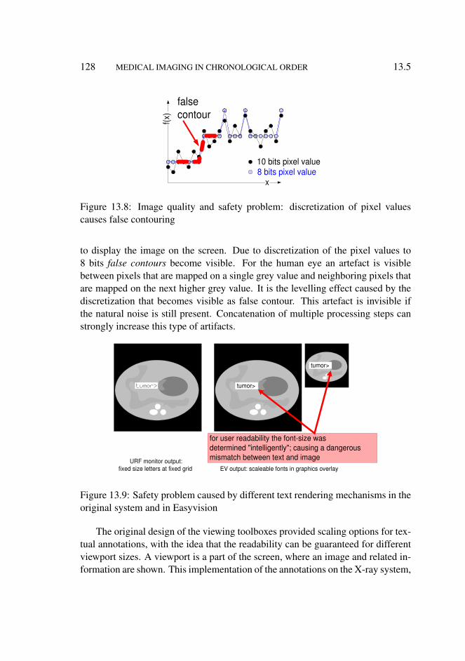
128 MEDICAL IMAGING IN CHRONOLOGICAL ORDER 13.5
x
f(x)
false contour
10 bits pixel value 8 bits pixel value
Figure 13.8: Image quality and safety problem: discretization of pixel valuescauses false contouring
to display the image on the screen. Due to discretization of the pixel values to8 bits false contours become visible. For the human eye an artefact is visiblebetween pixels that are mapped on a single grey value and neighboring pixels thatare mapped on the next higher grey value. It is the levelling effect caused by thediscretization that becomes visible as false contour. This artefact is invisible ifthe natural noise is still present. Concatenation of multiple processing steps canstrongly increase this type of artifacts.
for user readability the font-size was determined "intelligently"; causing a dangerous mismatch between text and image URF monitor output:
fixed size letters at fixed grid
tumor>
EV output: scaleable fonts in graphics overlay
tumor>
Figure 13.9: Safety problem caused by different text rendering mechanisms in theoriginal system and in Easyvision
The original design of the viewing toolboxes provided scaling options for tex-tual annotations, with the idea that the readability can be guaranteed for differentviewport sizes. A viewport is a part of the screen, where an image and related in-formation are shown. This implementation of the annotations on the X-ray system,
13.6 SUMMARY 129
however, conflicts in a dangerous way with this model of scalable annotations, seeFigure 13.9.
The annotations in the X-ray room are made on a fixed character grid. Some-times the ’>’ and ’<’ characters are used as arrows, in the figure they point to thetumor. The text rendering in the medical imaging workstation is not based on afixed character grid; often the texts will be rendered in variable-width characters.The combination of interface and variable-width characters is already quite diffi-cult. The font scaling destroys the remaining part of the text-image relationship,with the immediate danger that the annotation is pointing to the wrong position.
The solution that has been chosen is to define an encompassing rectangle at theinterface level and to render the text in a best fit effort within this encompassingrectangle. This strategy maintains the image-text relationship.
13.6 Summary
The development of the Easyvision RF started in 1991, with the perception thatmost of the software was available. During the developement phase it becameclear that a significant amount of functionality had to be added in the area ofprinting. Chapter 14 will show the importance of the printing fumctionality. Per-formance and safety problems popped up during the integration phase. Chapter 15will show the design to cope with these problems.

130 MEDICAL IMAGING IN CHRONOLOGICAL ORDER 13.6

Chapter 14
Medical Imaging Workstation:CAF Views
14.1 Introduction
This chapter discusses the Customer Objectives, Application and Functional viewsof the Medical Imaging Workstation. Section 14.2 describes the radiology con-text. Section 14.3 describes the typical application of the system. Section 14.4shows the key driver graph, from customer key drivers to system requirements, ofthe Medical Imaging Workstation. Section 14.5 shows the development of func-tionality of the family of medical imaging workstations in time. Section 14.6discusses the need for standardization of information to enable interoperability ofsystems within the department and the broader scope of the hospital. The conclu-sion is formulated in section 14.7.
14.2 Radiology Context
The medical imaging workstation is used in the radiology department as an add-on to URF X-ray systems. The main objective of the radiologist is to providediagnostic information, based on imaging, to the referring physician. In case ofgastrointestinal problems X-ray images are used, where the contrast is increasedby digestion of barium meal.
The work of the radiologist fits in an overall clinical flow, see Figure 14.1.The starting point is the patient visiting the family doctor. The family doctor canrefer to a consultant; for gastrointestinal problems the consultant is an internist.
131

132 MEDICAL IMAGING WORKSTATION: CAF VIEWS 14.2
radiology department family doctor
patient
referring physician
nurse, operator
radiologist
consult
request request
report report
findings film
film image image
interaction
interaction
interaction
paper or el. form
electronic
human interaction intense weak
legend
Figure 14.1: The clinical context of the radiology department, with its main stake-holders
The family doctor writes a request to this consultant. In the end the family doctorreceives a report from the consultant.
Next the patient makes an appointment with the consultant. The consultantwill do his own examination of the patient. Some of the examinations are notdone by the consultant. Imaging, for example, is done by radiologist. From theviewpoint of the radiologist the consultant is the referring physician. The referringphysician uses a request form to indicate the examination that is needed.
The patient makes an appointment via the administration of the radiology de-partment. The administration will schedule the examination. The examination isdone by hospital personnel (nurses, operator) under supervision of the radiologist.Most contact is between nurse and patient; contact between radiologist and patientis minimal.
The outcome of the imaging session in the examination room is a set of filmswith all the images that have been made. The radiologist will view these filmslater that day. He will dictate his findings, which are captured in written formatand sent to the referring physician. The referring physician performs the overalldiagnosis and discusses the diagnosis and, if applicable, the treatment with thepatient.
The radiology department fits in a complex financial context, see Figure 14.2.The patient is the main subject from a clinical point of view, but plays a rather lim-ited role in the financial flow. The patient is paying for insurance, which decoupleshim from the rest of the financial context.

14.2 RADIOLOGY CONTEXT 133
radiology
hospital admini- stration
government insurance
patient
equipment and service providers
facilities
schedules re
gula
tions
bu
dget
payment
budget
bill eq
uipm
ent
serv
ices
paym
ent
paym
ent
payment budget
equipment services
payment
regulations budget
Figure 14.2: The financial context of the radiology department
The insurance company and the government have a strong interest in cost con-trol1. They try to implement this by means of regulations and budgets. Note thatthese regulations vary widely over the different countries. France, for instance,has stimulated digitalization of X-ray imaging by higher reimbursements for digi-tal images. The United States regulation is much less concerned with cost control,here the insurance companies participate actively in the health care chain to con-trol the cost.
The hospital provides facilities and services for the radiology department. Thefinancial decomposition between radiology department and hospital is not alwaysentirely clear. They are mutually dependent.
The financial context is modeled in Figure 14.2 in a way that looks like theCalculating with Concepts technique, described by Dijkman et al in [22]. Thediagram as it is used here, however, is much less rigorous as the approach of Dijk-man. In this type of development the main purpose of these diagrams is buildinginsight in the broader context. The rigorous understanding, as proposed by Dijk-man, requires more time and is not needed for the purpose here. Most elements
1sometimes it even appears that that is the main interest, quality of health care appears than tobe of secondary importance

134 MEDICAL IMAGING WORKSTATION: CAF VIEWS 14.2
in the diagram will not even have a formal interface with the product to be cre-ated. Note also that the diagram is a simplification of the reality: the exact rolesand relations depend on the country, the culture and the type of department. Forexample a university hospital in France is different from a commercial imagingcenter in the USA. Whenever entities at this level are to be interfaced with themedical imaging workstation then an analysis is needed of the greatest commondenominator to be able to define a rigorous interface.
modalities from other vendors
HIS
Philips modalities
PACS
RIS
IT infrastructure
CIS LIS
generic
clinical specific info
image workflow
modality systems
medical imaging workstation modality enhancement
administrative mainframes
archive report review tele print
legend
Figure 14.3: Application layering of IT systems
The medical imaging workstation is playing a role in the information flow inthe hospital, it is part of the large collection of IT systems. Figure 14.3 shows alayered model of IT systems in the hospital, to position this product in the IT con-text. It is a layered model, where the lower layers provide the more generic func-tionality and the higher layers provide the more specific clinical imaging function-ality.
In the hospital a normal generic IT infrastructure is present, consisting of net-works, servers, PC’s and mainframes. More specialized systems provide clinicalinformation handling functions for different hospital departments (LIS for lab-oratory, CIS for cardio and RIS for radiology) and for the entire hospital (HISHospital Information System).
The generic imaging infrastructure is provided by the PACS (Picture Archiv-ing and Communication System). This is a networked system, with more spe-cialized nodes for specific functions, such as reporting, reviewing, demonstration,teaching and remote access.
The medical imaging workstation is positioned as a modality enhancer: an

14.2 RADIOLOGY CONTEXT 135
add-on to the modality product to enhance productivity and quality of the exam-ination equipment. The output of the modality enhancer is an improved set ofviewable images for the PACS.
information handling
image handling
archiving
imaging and treatment
base technology
localised patient focus safety critical limited variation due to "nature":
human anatomy pathologies imaging physics
distributed limited variation due to "nature":
human anatomy pathologies imaging physics
entirely distributed wide variation due to "socio-geographics":
psycho-social, political, cultural factors
service business not health care specific
extreme robust fire, earthquake, flood proof
life time 100 yrs (human life)
not health care specific short life-cycles rapid innovation
Figure 14.4: Reference model for health care automation
Figure 14.4 shows a reworked copy of the reference model for image handlingfunctions from the “PACS Assessment Final Report”, September 1996 [18]. Thisreference model is classifying application areas on the basis of those characteris-tics that have a great impact on design decisions, such as the degree of distribution,the degree and the cause of variation and life-cycle.
Imaging and treatment functions are provided of modality systems with thefocus on the patient. Safety plays an important role, in view of all kinds of haz-ards such as radiation, RF power, mechanical movements et cetera. The variationbetween systems is mostly determined by:
• the acquisition technology and its underlying physics principles.• the anatomy to be imaged• the pathology to be imaged
The complexity of these systems is mostly in the combination of many technolo-gies at state-of-the-art level.
Image handling functions (where the medical imaging workstation belongs)are distributed over the hospital, with work-spots where needed. The safety relatedhazards are much more indirect (identification, left-right exchange). The variation
136 MEDICAL IMAGING WORKSTATION: CAF VIEWS 14.2
is more or less the same as the modality systems: acquisition physics, anatomyand pathology.
The information handling systems are entirely distributed, information needsto be accessible from everywhere. A wide variation in functionality is caused by“social-geographic” factors:
• psycho-social factors• political factors• cultural factors• language factors
These factors influence what information must be stored (liability), or must notbe stored (privacy), how information is to be presented and exchanged, who mayaccess that information, et cetera.
The archiving of images and information in a robust and reliable way is ahighly specialized activity. The storage of information in such a way that it sur-vives fires, floods, and earthquakes is not trivial2. Specialized service providersoffer this kind of storage, where the service is location-independent thanks to thehigh-bandwidth networks.
All of these application functions build on top of readily available IT compo-nents: the base technology. These IT components are innovated rapidly, resultingin short component life-cycles. Economic pressure from other domains stimulatethe rapid innovation of these technologies. The amount of domain-specific tech-nology that has to be developed is decreasing, and is replaced by base technology.
Figure 14.5 comes from the same report [18] showing the information flowwithin this reference model. During this flow the clinical value is increasing:annotations, comments, and anamnesis can be added during and right after theacquisition. The preparation for the diagnosis adds analysis results, optimizeslayout and presentation settings, and pre-selects images. Finally the diagnosis isthe required added value, to be delivered to the referring physician.
At the same time the richness of the image is decreasing. The richness ofthe image is how much can be done with the pixels in the image. The imagesafter acquisition are very rich, all manipulation is still possible. When leaving theacquisition system the image is exported as a system independent image, wherea certain trade-off between size, performance, image quality, and manipulation
2Today terrorist attacks need to be included in this list full of disasters, and secure needs to beadded to the required qualities.

14.2 RADIOLOGY CONTEXT 137
prepare diagnosis diagnosis acquire
images report
authorise
archive
clinical review
education
research
demonstra- tion
treatment planning time
richness
clinical value
medical imaging
workstation
Figure 14.5: Clinical information flow
flexibility is made. This is an irreversible step in which some information is in-herently lost. The results of the preparation for diagnosis are often frozen, so thatno accidental changes can be made afterwards. Because this is the image used todiagnose, it is also archived to ensure liability. The archived result is similar to anelectronic photo, only a limited set of manipulations can still be performed on it.
Cardiovascular "high end"
high performance extensive functionality
Radiography "low end"
patient throughput simple functionality
URF universality "workhorse"
high end URF +vascular functionality
low end URF price fighter
mid end URF
Figure 14.6: URF market segmentation
The first releases of the medical imaging workstation, as described in this case,are used in conjunction with URF (Universal Radiography Fluoroscopy) systems.This family of systems is a mid-end type of X-ray system, see Figure 14.6. At

138 MEDICAL IMAGING WORKSTATION: CAF VIEWS 14.3
the high end cardiovascular systems are used, with high clinical added value and acorresponding price tag. At the low end “radiography” systems offer straight for-ward imaging functionality, oriented at patient throughput. Approximately 70%of all X-ray examinations are radiographic exposures.
The URF systems overlap with cardiovascular and radiography market seg-ments: high end URF systems also offer vascular functionality. Low end URFsystems must fit in radiography constraints. The key driver of URF systems is theuniversality, providing logistic flexibility in the hospital.
14.3 Typical Case
The specification and design of the medical imaging workstation was based on“typical” cases. Figure 14.7 shows the typical case for URF examinations. Threeexamination rooms are sharing one medical imaging workstation. Every examina-tion room has an average throughput of 4 patients per hour (patient examinationsare interleaved, as explained below for Figure 14.8).
exam room 1
exam room 3
exam room 2
image production: 20 1024 2 8 bit images per examination
3 examination rooms connected to
examination room: average 4 interleaved examinations / hour
film production: 3 films of 4k*5k pixels each
1 medical imaging workstation + printer
high quality output (bi-cubic interpolation)
Figure 14.7: Typical case URF examination
The average image production per examination is 20 images, each of 10242
pixels of 8 bits. The images are printed on large film sheets with a size of approx-imately 24 ∗ 30cm2. One film sheet consists of 4k by 5k pixels. The images mustbe sufficiently large to be easily viewed on the lightbox. These images are typi-cally printed on 3 film sheets. Image quality of the film sheets is crucial, whichtranslates into the use of bi-cubic interpolation.
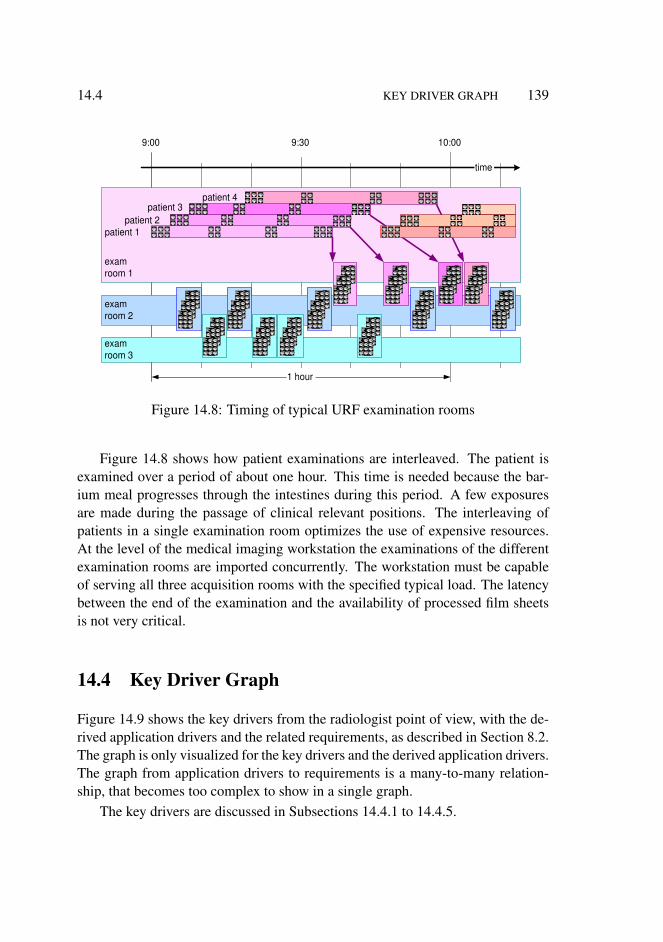
14.4 KEY DRIVER GRAPH 139
exam room 1
exam room 2
exam room 3
1 hour
time
9:00 10:00 9:30
patient 1 patient 2
patient 3 patient 4
Figure 14.8: Timing of typical URF examination rooms
Figure 14.8 shows how patient examinations are interleaved. The patient isexamined over a period of about one hour. This time is needed because the bar-ium meal progresses through the intestines during this period. A few exposuresare made during the passage of clinical relevant positions. The interleaving ofpatients in a single examination room optimizes the use of expensive resources.At the level of the medical imaging workstation the examinations of the differentexamination rooms are imported concurrently. The workstation must be capableof serving all three acquisition rooms with the specified typical load. The latencybetween the end of the examination and the availability of processed film sheetsis not very critical.
14.4 Key Driver Graph
Figure 14.9 shows the key drivers from the radiologist point of view, with the de-rived application drivers and the related requirements, as described in Section 8.2.The graph is only visualized for the key drivers and the derived application drivers.The graph from application drivers to requirements is a many-to-many relation-ship, that becomes too complex to show in a single graph.
The key drivers are discussed in Subsections 14.4.1 to 14.4.5.
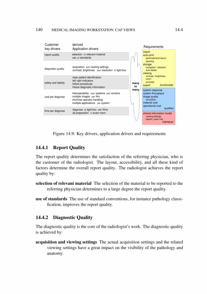
140 MEDICAL IMAGING WORKSTATION: CAF VIEWS 14.4
many to
many
report quality
diagnostic quality
safety and liability
cost per diagnose
time per diagnose
Customer key drivers Requirements
diagnose at light-box with films all preparation in exam room
interoperability over systems and vendors multiple images per film minimise operator handling multiple applications per system
clear patient identification left right indicators follow procedures freeze diagnostic information
derived Application drivers
acquisition and viewing settings contrast, brightness and resolution of light-box
selection of relevant material use of standards
import auto-print
parameterized layout spooling
storage navigation / selection auto-delete
viewing contrast / brightness zoom annotate
export
system response system throughput image quality
annotation material cost operational cost
shared information model viewing settings patient, exam info
functionality
qualities
interfaces
Figure 14.9: Key drivers, application drivers and requirements
14.4.1 Report Quality
The report quality determines the satisfaction of the referring physician, who isthe customer of the radiologist. The layout, accessibility, and all these kind offactors determine the overall report quality. The radiologist achieves the reportquality by:
selection of relevant material The selection of the material to be reported to thereferring physician determines to a large degree the report quality.
use of standards The use of standard conventions, for instance pathology classi-fication, improves the report quality.
14.4.2 Diagnostic Quality
The diagnostic quality is the core of the radiologist’s work. The diagnostic qualityis achieved by:
acquisition and viewing settings The actual acquisition settings and the relatedviewing settings have a great impact on the visibility of the pathology andanatomy.
14.4 KEY DRIVER GRAPH 141
contrast, brightness and resolution of lightbox The lightbox has a very gooddiagnostic image quality: high brightness, high resolution, and many im-ages can be shown simultaneously.
14.4.3 Safety and Liability
Erroneous diagnoses are dangerous for the patient; the radiologist might be suedfor mistakes. Also mistakes in the related annotations (wrong patient name, wrongposition) are a safety risk for the patient and hence a liability risk for the radiolo-gist. The derived application drivers for safety and liability are:
clear patient identification Erroneous patient identification is a safety risk.
left right indicators Erroneous positioning information is a safety risk. Left-right exchanges are notoriously dangerous.
follow procedures Clinical procedures reduce the chance of human errors. Fol-lowing these procedures lowers the liability for the radiologist.
freeze diagnostic information Changing image information after the diagnosisis a liability risk: different interpretations are possible, based on the changes.
14.4.4 Cost per Diagnosis
Insurance and government generate a lot of cost pressure. Cost efficiency can beexpressed in cost per diagnosis. The cost per diagnosis is reduced in the followingways:
interoperability over systems and vendors Mix and match of systems, not con-strained by vendor or system lock-ins, allow the radiology department tooptimize the mix of acquisition systems to the local needs.
multiple images per film Film is a costly resource (based on silver). Efficiencyof film real estate is immediately cost efficient. A positive side effect is thatfilm efficiency is also beneficial for viewing on the lightbox, because theimages are then put closer together.
minimize operator handling Automation of repeated actions will reduce the amountof personnel needed, which again is a cost reduction. An example is the useof predefined and propagated settings that streamline the flow of informa-tion. This is a cost reduction, but most of all it improves the conveniencefor the users.
142 MEDICAL IMAGING WORKSTATION: CAF VIEWS 14.4
multiple applications per system Universality of acquisition system and work-station provides logistics flexibility in the radiology department. This willin the end result in lower cost.
14.4.5 Time per Diagnosis
Time efficiency is partially a cost factor, see 14.4.4, but it is also a personal satis-faction issue for the radiologist. The time per diagnosis is reduced by the follow-ing means:
diagnose at lightbox with films This allows a very fast interaction: zooming isdone by a single head movement, and the next patient is reached by onebutton, that exchanges the films mechanically in a single move.
all preparation in exam room The personnel operating the examination roomalso does the preparation for the diagnosis. This work is done on the fly,interleaved with the examination work.
14.4.6 Functional Requirements
The functionality that is needed for to realize the derived application drivers is:
import The capability to import data into the workstation data store in a mean-ingful way.
autoprint The capability to print the image set without operator intervention:
parametrized layout Film layout under control of the remote acquisitionsystem.
spooling Support for concurrent import streams, which have to be printedby a single printer.
storage The capability to store about one day of examinations at the workstation,both as a buffer and to enable later review:
navigation/selection The capability to find and select the patient, exami-nation and images.
autodelete The capability to delete images when they are printed and nolonger needed. This function allows the workstation to be used in anoperator free server. The import, print and auto-delete run continu-ously as a standard sequence.
14.5 KEY DRIVER GRAPH 143
viewing All functions to show and manipulate images, the most frequently usedsubset:
contrast/brightness Very commonly used grey-level user interface.zoom Enlarge part of the image.annotate Add textual or graphic annotations to the image.
export Transfer of images to other systems.
Note that the import, storage and autoprint functionality are core to satisfy thekey drivers, while the viewing and export functionality is only nice to have.
14.4.7 Quality Requirements
The following qualities need to be specified quantitatively:
system response Determines the speed and satisfaction of preparing the diagno-sis by means of the workstation.
system throughput As defined by the typical case.
image quality Required for preparation of the diagnosis on screen and for diag-nosis from film. Specific quality requirements exists for the relation be-tween image and annotation:
annotation The relation between annotation and image is clinically rele-vant and must be reproducible.
material cost The cost price of the system must fit in the cost target.
operational cost The operational cost (cost of consumables, energy, et cetera)must fit in the operational target.
14.4.8 Interface Requirements
Key part of the external interfaces is the shared information model that facilitatesinteroperability between different systems. The cooperating systems must adhereto a shared information model. Elements of such an information model are:
viewing settings Sharing the same presentation model to guarantee the same dis-played image at both systems.
patient, exam info Sharing the same meta information for navigation and identi-fication.
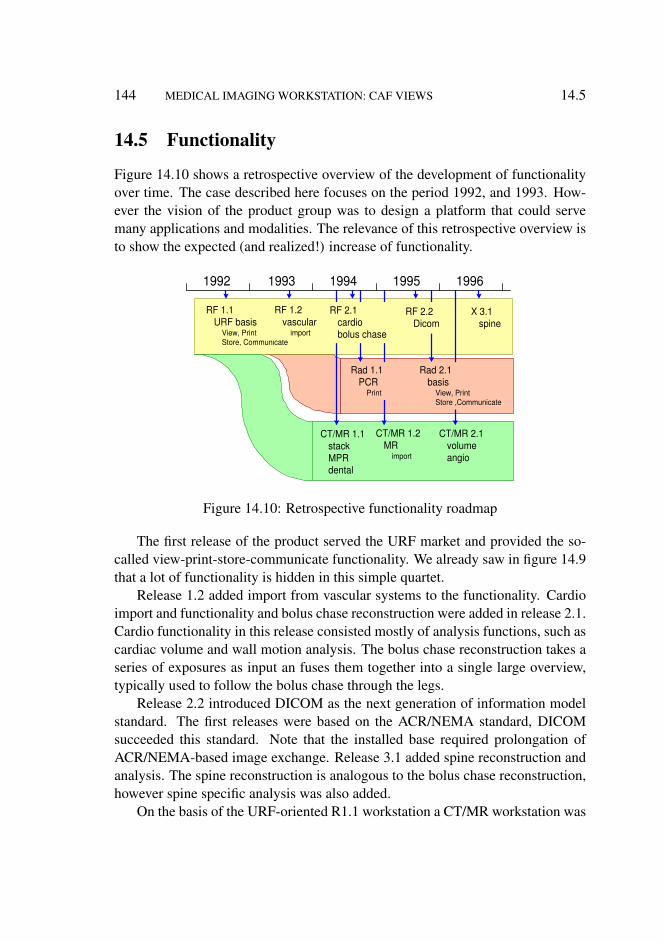
144 MEDICAL IMAGING WORKSTATION: CAF VIEWS 14.5
14.5 Functionality
Figure 14.10 shows a retrospective overview of the development of functionalityover time. The case described here focuses on the period 1992, and 1993. How-ever the vision of the product group was to design a platform that could servemany applications and modalities. The relevance of this retrospective overview isto show the expected (and realized!) increase of functionality.
1992 1993 1994 1995 1996
RF 1.1 URF basis
View, Print Store, Communicate
RF 1.2 vascular
import
RF 2.1 cardio bolus chase
RF 2.2 Dicom
X 3.1 spine
Rad 2.1 basis
View, Print Store ,Communicate
Rad 1.1 PCR
CT/MR 1.1 stack MPR dental
CT/MR 1.2 MR
import
CT/MR 2.1 volume angio
Figure 14.10: Retrospective functionality roadmap
The first release of the product served the URF market and provided the so-called view-print-store-communicate functionality. We already saw in figure 14.9that a lot of functionality is hidden in this simple quartet.
Release 1.2 added import from vascular systems to the functionality. Cardioimport and functionality and bolus chase reconstruction were added in release 2.1.Cardio functionality in this release consisted mostly of analysis functions, such ascardiac volume and wall motion analysis. The bolus chase reconstruction takes aseries of exposures as input an fuses them together into a single large overview,typically used to follow the bolus chase through the legs.
Release 2.2 introduced DICOM as the next generation of information modelstandard. The first releases were based on the ACR/NEMA standard, DICOMsucceeded this standard. Note that the installed base required prolongation ofACR/NEMA-based image exchange. Release 3.1 added spine reconstruction andanalysis. The spine reconstruction is analogous to the bolus chase reconstruction,however spine specific analysis was also added.
On the basis of the URF-oriented R1.1 workstation a CT/MR workstation was

14.6 INTEROPERABILITY VIA INFORMATION MODEL 145
developed, which was released in 1994. CT/MR images are slice-based (insteadof projection-based as in URF), which prompted the development of a stack viewapplication (fast scrolling through a stack of images). Reconstruction of obliqueand curved slices is supported by means of MPR (Multi Planar Reformatting). Ahighly specialized application was built on top of these applications. This wasa dental package, allowing viewing of the jaws, with the molars, and with therequired cross sections.
Release 2.1 of the CT/MR workstation added a much more powerful volumeviewing application and a more specialized angio package, with viewing and anal-ysis capability.
Also derived from the RF workstation a radiography workstation was built.R1.1 of this system was mostly a print server, while R2.1 supported the full view-print-store-communicate functionality.
The commercial, service and goods flow decompositions were present as partof the formalized documentation (TPD).
14.6 Interoperability via Information Model
The health care industry is striving for interoperability by working on standardexchange formats and protocols. The driving force behind this standardization isthe ACR/NEMA, in which equipment manufacturers participate in the standard-ization process.
DICOM ACR/NEMA
Philips GE Siemens
cardio vascular
MRI CT medical imaging
RF bolus chase
vascular analyse
vendor
world standard
product family
applications
URF
cardio analyse
high innovation rate
high interoperability
glob
al s
tand
ardi
zatio
n ta
kes
mor
e th
an 5
yea
rs
legend
Figure 14.11: Information model, standardization for interoperability
Standardization and innovation are often opposing forces. The solution is
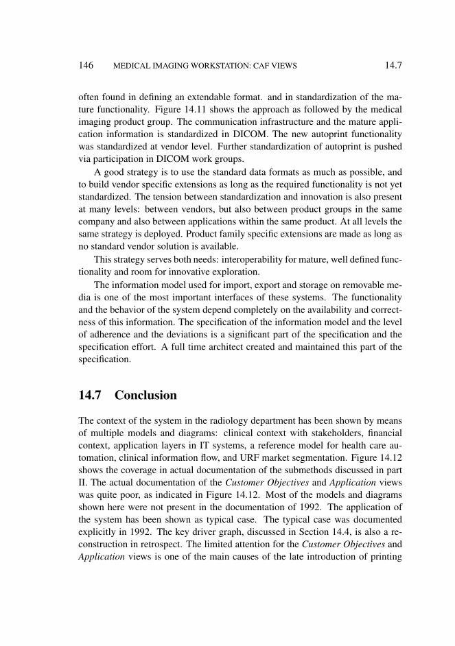
146 MEDICAL IMAGING WORKSTATION: CAF VIEWS 14.7
often found in defining an extendable format. and in standardization of the ma-ture functionality. Figure 14.11 shows the approach as followed by the medicalimaging product group. The communication infrastructure and the mature appli-cation information is standardized in DICOM. The new autoprint functionalitywas standardized at vendor level. Further standardization of autoprint is pushedvia participation in DICOM work groups.
A good strategy is to use the standard data formats as much as possible, andto build vendor specific extensions as long as the required functionality is not yetstandardized. The tension between standardization and innovation is also presentat many levels: between vendors, but also between product groups in the samecompany and also between applications within the same product. At all levels thesame strategy is deployed. Product family specific extensions are made as long asno standard vendor solution is available.
This strategy serves both needs: interoperability for mature, well defined func-tionality and room for innovative exploration.
The information model used for import, export and storage on removable me-dia is one of the most important interfaces of these systems. The functionalityand the behavior of the system depend completely on the availability and correct-ness of this information. The specification of the information model and the levelof adherence and the deviations is a significant part of the specification and thespecification effort. A full time architect created and maintained this part of thespecification.
14.7 Conclusion
The context of the system in the radiology department has been shown by meansof multiple models and diagrams: clinical context with stakeholders, financialcontext, application layers in IT systems, a reference model for health care au-tomation, clinical information flow, and URF market segmentation. Figure 14.12shows the coverage in actual documentation of the submethods discussed in partII. The actual documentation of the Customer Objectives and Application viewswas quite poor, as indicated in Figure 14.12. Most of the models and diagramsshown here were not present in the documentation of 1992. The application ofthe system has been shown as typical case. The typical case was documentedexplicitly in 1992. The key driver graph, discussed in Section 14.4, is also a re-construction in retrospect. The limited attention for the Customer Objectives andApplication views is one of the main causes of the late introduction of printing
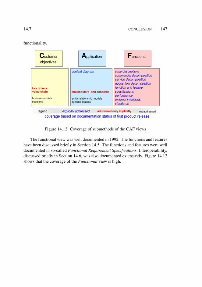
14.7 CONCLUSION 147
functionality.
C ustomer objectives
A pplication F unctional
key drivers value chain
business models suppliers
context diagram
stakeholders and concerns
entity relationship models dynamic models
case descriptions commercial decomposition service decomposition goods flow decomposition function and feature specifications performance external interfaces standards
explicitly addressed addressed only implicitly not addressed
coverage based on documentation status of first product release legend
Figure 14.12: Coverage of submethods of the CAF views
The functional view was well documented in 1992. The functions and featureshave been discussed briefly in Section 14.5. The functions and features were welldocumented in so-called Functional Requirement Specifications. Interoperability,discussed briefly in Section 14.6, was also documented extensively. Figure 14.12shows that the coverage of the Functional view is high.

148 MEDICAL IMAGING WORKSTATION: CAF VIEWS 14.7
Chapter 15
Medical Imaging Workstation:CR Views
15.1 Introduction
The conceptual and realization views are described together in this chapter. Therealization view, with its specific values, brings the concepts more alive.
Section 15.2 describes the processing pipeline for presentation and rendering,and maps the user interface on these concepts. Section 15.4 describes the conceptsneeded for memory management, and zooms in on how the memory managementis used to implement the processing pipeline. Section 15.3 describes the softwarearchitecture. Section 15.5 describes how the limited amount of CPU power ismanaged.
The case material is based on actual data, from a complex context with largecommercial interests. The material is simplified to increase the accessibility, whileat the same time small changes have been made to remove commercial sensitivity.Commercial sensitivity is further reduced by using relatively old data (between 8and 13 years in the past). Care has been taken that the value of the case descriptionis maintained.
15.2 Image Quality and Presentation Pipeline
The user views the image during the examination at the console of the X-raysystem, mostly to verify the image quality and to guide the further examination.Later the same image is viewed again from film to determine the diagnosis and to
149
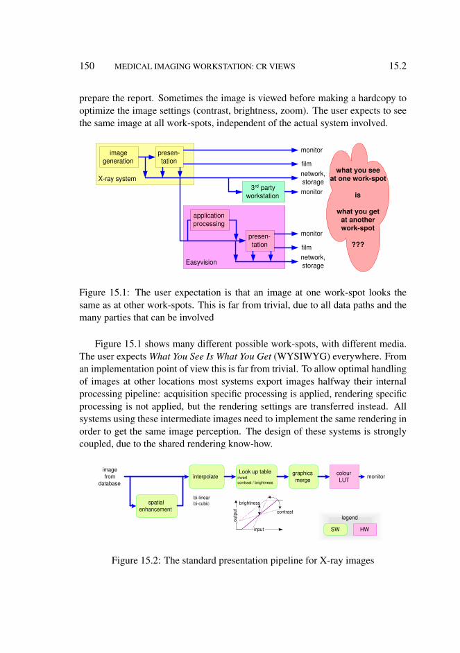
150 MEDICAL IMAGING WORKSTATION: CR VIEWS 15.2
prepare the report. Sometimes the image is viewed before making a hardcopy tooptimize the image settings (contrast, brightness, zoom). The user expects to seethe same image at all work-spots, independent of the actual system involved.
what you see at one work-spot
is
what you get at another work-spot
???
X-ray system
image generation
presen- tation
monitor
film network, storage
Easyvision
application processing
presen- tation
monitor
film network, storage
3 rd party workstation monitor
Figure 15.1: The user expectation is that an image at one work-spot looks thesame as at other work-spots. This is far from trivial, due to all data paths and themany parties that can be involved
Figure 15.1 shows many different possible work-spots, with different media.The user expects What You See Is What You Get (WYSIWYG) everywhere. Froman implementation point of view this is far from trivial. To allow optimal handlingof images at other locations most systems export images halfway their internalprocessing pipeline: acquisition specific processing is applied, rendering specificprocessing is not applied, but the rendering settings are transferred instead. Allsystems using these intermediate images need to implement the same rendering inorder to get the same image perception. The design of these systems is stronglycoupled, due to the shared rendering know-how.
spatial enhancement
interpolate Look up table
invert contrast / brightness
graphics merge
colour LUT
HW SW
monitor image from
database
outp
ut
input
contrast
brightness bi-linear bi-cubic
legend
Figure 15.2: The standard presentation pipeline for X-ray images
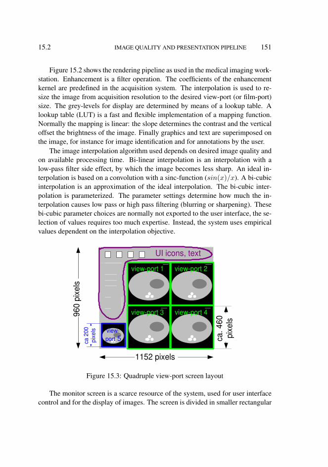
15.2 IMAGE QUALITY AND PRESENTATION PIPELINE 151
Figure 15.2 shows the rendering pipeline as used in the medical imaging work-station. Enhancement is a filter operation. The coefficients of the enhancementkernel are predefined in the acquisition system. The interpolation is used to re-size the image from acquisition resolution to the desired view-port (or film-port)size. The grey-levels for display are determined by means of a lookup table. Alookup table (LUT) is a fast and flexible implementation of a mapping function.Normally the mapping is linear: the slope determines the contrast and the verticaloffset the brightness of the image. Finally graphics and text are superimposed onthe image, for instance for image identification and for annotations by the user.
The image interpolation algorithm used depends on desired image quality andon available processing time. Bi-linear interpolation is an interpolation with alow-pass filter side effect, by which the image becomes less sharp. An ideal in-terpolation is based on a convolution with a sinc-function (sin(x)/x). A bi-cubicinterpolation is an approximation of the ideal interpolation. The bi-cubic inter-polation is parameterized. The parameter settings determine how much the in-terpolation causes low pass or high pass filtering (blurring or sharpening). Thesebi-cubic parameter choices are normally not exported to the user interface, the se-lection of values requires too much expertise. Instead, the system uses empiricalvalues dependent on the interpolation objective.
view-port 1 view-port 2
view-port 3 view-port 4
view- port 5
UI icons, text
1152 pixels
960
pixe
ls
ca. 4
60
pixe
ls
ca 2
00
pixe
ls
Figure 15.3: Quadruple view-port screen layout
The monitor screen is a scarce resource of the system, used for user interfacecontrol and for the display of images. The screen is divided in smaller rectangular
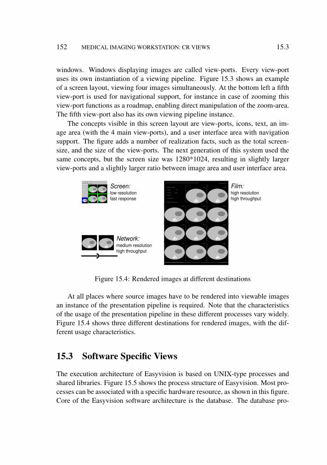
152 MEDICAL IMAGING WORKSTATION: CR VIEWS 15.3
windows. Windows displaying images are called view-ports. Every view-portuses its own instantiation of a viewing pipeline. Figure 15.3 shows an exampleof a screen layout, viewing four images simultaneously. At the bottom left a fifthview-port is used for navigational support, for instance in case of zooming thisview-port functions as a roadmap, enabling direct manipulation of the zoom-area.The fifth view-port also has its own viewing pipeline instance.
The concepts visible in this screen layout are view-ports, icons, text, an im-age area (with the 4 main view-ports), and a user interface area with navigationsupport. The figure adds a number of realization facts, such as the total screen-size, and the size of the view-ports. The next generation of this system used thesame concepts, but the screen size was 1280*1024, resulting in slightly largerview-ports and a slightly larger ratio between image area and user interface area.
Screen: low resolution fast response
Film: high resolution high throughput
Network: medium resolution high throughput
Figure 15.4: Rendered images at different destinations
At all places where source images have to be rendered into viewable imagesan instance of the presentation pipeline is required. Note that the characteristicsof the usage of the presentation pipeline in these different processes vary widely.Figure 15.4 shows three different destinations for rendered images, with the dif-ferent usage characteristics.
15.3 Software Specific Views
The execution architecture of Easyvision is based on UNIX-type processes andshared libraries. Figure 15.5 shows the process structure of Easyvision. Most pro-cesses can be associated with a specific hardware resource, as shown in this figure.Core of the Easyvision software architecture is the database. The database pro-
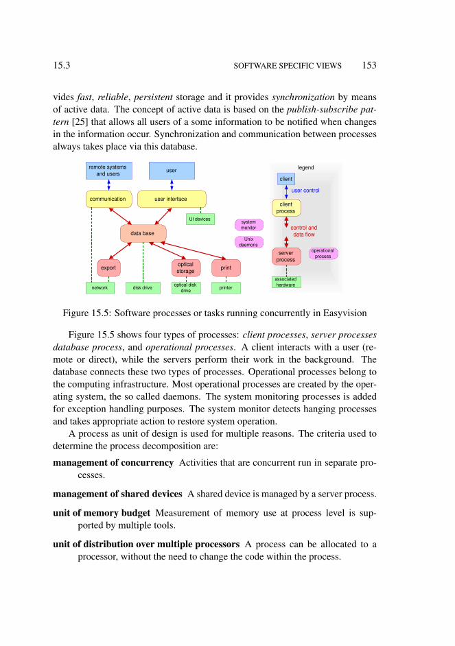
15.3 SOFTWARE SPECIFIC VIEWS 153
vides fast, reliable, persistent storage and it provides synchronization by meansof active data. The concept of active data is based on the publish-subscribe pat-tern [25] that allows all users of a some information to be notified when changesin the information occur. Synchronization and communication between processesalways takes place via this database.
user interface communication
data base
export print optical storage
optical disk drive printer disk drive network
UI devices system monitor
Unix daemons
client process
associated hardware
control and data flow
remote systems and users user
client
user control
server process
operational process
legend
Figure 15.5: Software processes or tasks running concurrently in Easyvision
Figure 15.5 shows four types of processes: client processes, server processesdatabase process, and operational processes. A client interacts with a user (re-mote or direct), while the servers perform their work in the background. Thedatabase connects these two types of processes. Operational processes belong tothe computing infrastructure. Most operational processes are created by the oper-ating system, the so called daemons. The system monitoring processes is addedfor exception handling purposes. The system monitor detects hanging processesand takes appropriate action to restore system operation.
A process as unit of design is used for multiple reasons. The criteria used todetermine the process decomposition are:
management of concurrency Activities that are concurrent run in separate pro-cesses.
management of shared devices A shared device is managed by a server process.
unit of memory budget Measurement of memory use at process level is sup-ported by multiple tools.
unit of distribution over multiple processors A process can be allocated to aprocessor, without the need to change the code within the process.

154 MEDICAL IMAGING WORKSTATION: CR VIEWS 15.4
unit of exception handling Faults are contained within the process boundaries.The system monitor observes at process level, because the operating systemprovides the means at process level.
Manageability, visibility and understandability benefit from a limited number ofprocesses. One general rule is to minimize the amount of processes, in the orderof magnitude of ten processes.
The presentation pipeline, as depicted in Figure 15.2, is used in the user inter-face process, the print server and the export server.
Figure 15.6 shows the software from the dependency point of view. Soft-ware in higher layers depends on, has explicit knowledge of, lower layers of thesoftware. Software in the lower layers should not depend on, or have explicitknowledge of software in higher layers.
DSI
3M RC
Desk, cabinets, cables, etc.
Standard IPX workstation DOR HC interf
RC interf
SunOS
NIX RC driver
HC driver
DOR driver
Spool HCU Store Image Gfx UI DB PMS- net in
PMS- net out
Medical Imaging R/F
Start up
Install
Config
SW keys
service
dev. tools Print Store View Cluster
operating system
toolbox
hardware
application functions
user interface
connected system
SW infrastructure
legend
Figure 15.6: Simplified layering of the software
The caption of Figure 15.6 explicitly states this diagram to be simplified. Theoriginal design of this software did not use the layering concept. The software hasbeen restructured in later years to make the dependency as layering explicit. Theactual number of layers based on larger packages did exceed 15. Reality is muchmore complex than this simplified diagram suggests.
15.4 Memory Management
The amount of memory in the medical imaging workstation is limited for costreasons, but also for simple physical reasons: the workstation used at that momentdid not support more than 64 MByte of physical memory. The workstation and
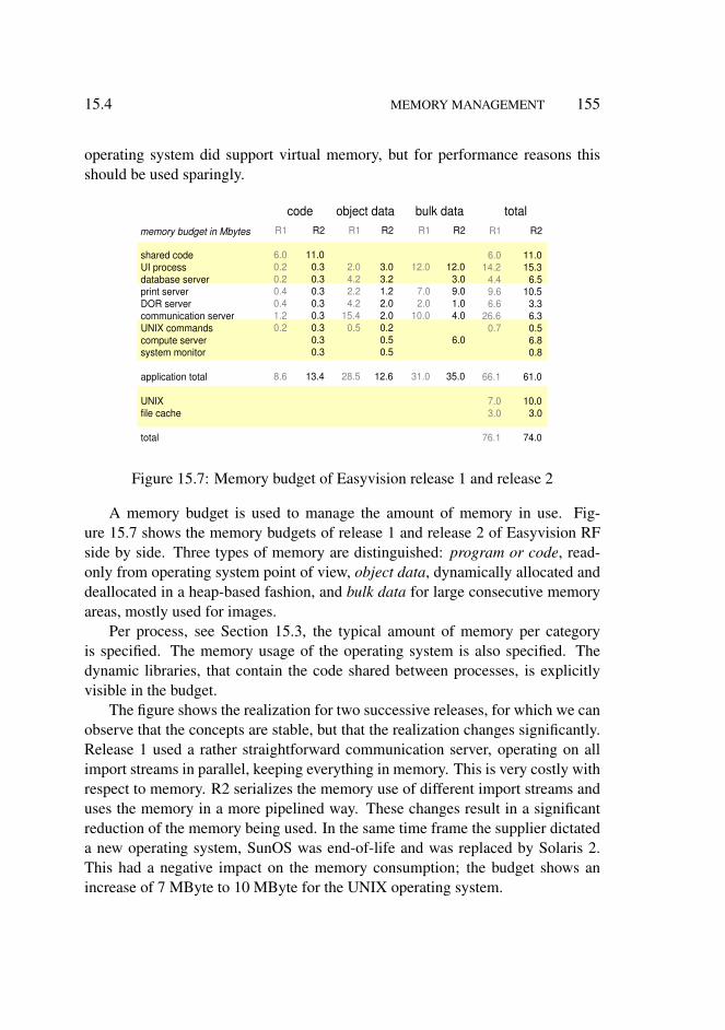
15.4 MEMORY MANAGEMENT 155
operating system did support virtual memory, but for performance reasons thisshould be used sparingly.
shared code UI process database server print server DOR server communication server UNIX commands compute server system monitor
application total
UNIX file cache
total
R1
2.0 4.2 2.2 4.2
15.4 0.5
28.5
R1
12.0
7.0 2.0
10.0
31.0
R1
6.0 0.2 0.2 0.4 0.4 1.2 0.2
8.6
R1
6.0 14.2
4.4 9.6 6.6
26.6 0.7
66.1
7.0 3.0
76.1
memory budget in Mbytes R2
11.0 0.3 0.3 0.3 0.3 0.3 0.3 0.3 0.3
13.4
R2
3.0 3.2 1.2 2.0 2.0 0.2 0.5 0.5
12.6
R2
12.0 3.0 9.0 1.0 4.0
6.0
35.0
R2
11.0 15.3
6.5 10.5
3.3 6.3 0.5 6.8 0.8
61.0
10.0 3.0
74.0
code object data bulk data total
Figure 15.7: Memory budget of Easyvision release 1 and release 2
A memory budget is used to manage the amount of memory in use. Fig-ure 15.7 shows the memory budgets of release 1 and release 2 of Easyvision RFside by side. Three types of memory are distinguished: program or code, read-only from operating system point of view, object data, dynamically allocated anddeallocated in a heap-based fashion, and bulk data for large consecutive memoryareas, mostly used for images.
Per process, see Section 15.3, the typical amount of memory per categoryis specified. The memory usage of the operating system is also specified. Thedynamic libraries, that contain the code shared between processes, is explicitlyvisible in the budget.
The figure shows the realization for two successive releases, for which we canobserve that the concepts are stable, but that the realization changes significantly.Release 1 used a rather straightforward communication server, operating on allimport streams in parallel, keeping everything in memory. This is very costly withrespect to memory. R2 serializes the memory use of different import streams anduses the memory in a more pipelined way. These changes result in a significantreduction of the memory being used. In the same time frame the supplier dictateda new operating system, SunOS was end-of-life and was replaced by Solaris 2.This had a negative impact on the memory consumption; the budget shows anincrease of 7 MByte to 10 MByte for the UNIX operating system.

156 MEDICAL IMAGING WORKSTATION: CR VIEWS 15.4
MB
ytes
time
10
20
nett used
used address space
gross used
Figure 15.8: Memory fragmentation increase. The difference between gross usedand nett used is the amount of unusable memory due to fragmentation
The decomposition in object data and bulk data is needed to prevent memoryfragmentation. Fragmentation of memory occurs when the allocation is dynamicwith different sizes of allocated memory over time. The fragmentation increasesover time. Due to the paging of the virtual memory system not all fragmentationis disastrous. Figure 15.8 shows the increase of the amount of memory over time.The net amount of memory stabilizes after some time, but the gross amount ofmemory increases due to ongoing fragmentation. The amount of virtual memoryin use (and the address space) is increasing even more, however a large part of thisvirtual memory is paged out and is not really a problem.
virtual memory
physical memory
memory management
unit disk storage
instruction and data
cache
heap memory, malloc() free()
allocator, chunk
view PixMap cache
print PixMap cache
cluster PixMap cache
operating system
toolbox
hardware
application functions
user interface
Medical imaging R/F cache sizes legend
Figure 15.9: Cache layers at the corresponding levels of Figure 15.6
The hardware and operating system support fast and efficient memory-basedon hardware caching and virtual memory, the lowest layer in Figure 15.9. Theapplication allocates memory via the heap memory management functions mal-
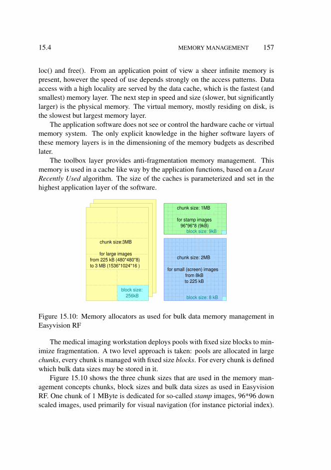
15.4 MEMORY MANAGEMENT 157
loc() and free(). From an application point of view a sheer infinite memory ispresent, however the speed of use depends strongly on the access patterns. Dataaccess with a high locality are served by the data cache, which is the fastest (andsmallest) memory layer. The next step in speed and size (slower, but significantlylarger) is the physical memory. The virtual memory, mostly residing on disk, isthe slowest but largest memory layer.
The application software does not see or control the hardware cache or virtualmemory system. The only explicit knowledge in the higher software layers ofthese memory layers is in the dimensioning of the memory budgets as describedlater.
The toolbox layer provides anti-fragmentation memory management. Thismemory is used in a cache like way by the application functions, based on a LeastRecently Used algorithm. The size of the caches is parameterized and set in thehighest application layer of the software.
chunk size:3MB
for large images from 225 kB (480*480*8) to 3 MB (1536*1024*16 )
block size: 256kB
chunk size: 2MB
for small (screen) images from 8kB to 225 kB
block size: 8 kB
chunk size: 1MB
for stamp images 96*96*8 (9kB)
block size: 9kB
Figure 15.10: Memory allocators as used for bulk data memory management inEasyvision RF
The medical imaging workstation deploys pools with fixed size blocks to min-imize fragmentation. A two level approach is taken: pools are allocated in largechunks, every chunk is managed with fixed size blocks. For every chunk is definedwhich bulk data sizes may be stored in it.
Figure 15.10 shows the three chunk sizes that are used in the memory man-agement concepts chunks, block sizes and bulk data sizes as used in EasyvisionRF. One chunk of 1 MByte is dedicated for so-called stamp images, 96*96 downscaled images, used primarily for visual navigation (for instance pictorial index).

158 MEDICAL IMAGING WORKSTATION: CR VIEWS 15.4
The block size of 9 kbytes is exactly the size of a stamp image. A second chunkof 3 MBytes is used for large images, for instance images with the original ac-quisition resolution. Small images, such as images at display resolution, will beallocated in the third chunk of 2 MBytes. The dimensioning of the block andchunk sizes is based on a priori know-how of the application of the system, as de-scribed in Section 14.3. The block sizes in the latter two chunks are 256 kbytes forlarge images and 8 kbytes for small images. These block sizes result in balancedand predictable memory utilization and fragmentation within a chunk.
raw image
resized image
enhanced image
grey- value image
view- port
gfx
text
retrieve enhance inter- polate
lookup merge display
Figure 15.11: Intermediate processing results are cached in an application levelcache
The chunks are used with cache like behavior: images are kept until the mem-ory is needed for other images. Figure 15.11 shows the cached intermediate re-sults. This figure is a direct transformation of the viewing pipeline in Figure 15.2,with the processing steps replaced by arrows and the data-arrows replaced bystores. In Section 15.5 the gain in response time is shown, which is obtainedby caching the intermediate images.
Figure 15.12 shows how the chunks are being used in quadruple viewing (Fig-ure 15.3). The 10242 images with a depth of 1 or 2 bytes will be stored in the3 MB chunks. The smaller interpolated images of 4602 will go into the 2 MBchunks, requiring 27 blocks of 8kB for an 1 byte pixel depth or 54 blocks for 2 2bytes per pixel. Also the screen size images of the navigation view-port fall in therange that maps on the 2 MB chunk, requiring 5 blocks per 2002 image.
Everything added together requires more blocks than available in the 2 and 3MB chunks. The cache mechanism will sacrifice the least recently used interme-diate results.
For memory and performance reasons the navigation view-port is using thestamp image as source image. This image, which is shown in a small view-port atthe left hand side of the screen, is only used for navigational support of the userinterface. Response time is here more important than image quality.
The print server uses a different memory strategy than the user interface pro-

15.5 MEMORY MANAGEMENT 159
Pixmap cache
viewport viewport viewport grey- value image
grey- value image
resized image
resized image
resized image
resized image
raw image raw
image raw
image raw
image resized image
grey- value image
gfx
text
retrieve enhance lookup merge display
viewport
4 * 1024 2
1 byte / pixel 4 * 460 2
2 byte / pixel 4 * 460 2
1 byte / pixel 4 * 460 2
1 byte / pixel
5 retrieve enhance interpolate lookup
96 2 200 2 96 2
merge display
raw image raw
image raw
image enhanced
image inter- polate
200 2 200 2
block size: 9kB
block size: 8 kB
block size: 256kB
4 * 1024 2
2 byte / pixel
1024 2 8 bit image requires 4 256kB blocks
8 1024 2 images require 48 256kB blocks 12 blocks shortage
460 2 image 8 bit requires 27 8kB blocks 200 2 images require 5 8kb blocks
all screen-size images require 334 8kB blocks, 78 blocks shortage
Figure 15.12: Example of allocator and cache use. In this use case not all interme-diate images fit in the cache, due to a small shortage of blocks. The performanceof some image manipulations will be decreased, because the intermediate imageswill be regenerated when needed.
cess, see Figure 15.13. The print server creates the film-image by rendering theindividual images. The film size of 4k*5k images is too large to render the entirefilm at once in memory: 20 Mpixels, while the memory budget allows 9 Mbyte ofbulk data usage. The film image itself is already more than the provided memorybudget!
The film image is built up in horizontal bands, which are sent to the laserprinter. The size of the stroke is chosen such that input image + intermediateresults + 2 bands (for double buffering) fit in the available bulk data budget. Atthe same time the band should not be very small because the banding increasesthe overhead and some duplicate processing is sometimes needed because of edgeeffects.
The print server uses the same memory management concepts as shown in thefigure with cache layers, Figure 15.9. However the application level caching doesnot provide any significant value for this server usage, because the image dataflow is straightforward and predictable.

160 MEDICAL IMAGING WORKSTATION: CR VIEWS 15.5
4k pixels
128 pixels 1024 pixels
original images
1024 pixels
Figure 15.13: Print server is based on different memory strategy, using bands
15.5 CPU Usage
The CPU is a limited resource for the Easyvision. The performance and through-put of the system depend strongly on the available processing power and the effi-ciency of using the processing power. CPU time and memory can be exchangedpartially, for instance by using caches to store intermediate results.
Figure 15.14 shows typical update speeds and processing times for a singleimage user interface layout. Contrast brightness (C/B in the figure) changes mustbe fast, to give immediate visual feedback when turning a contrast or brightnesswheel. Working on the cached resized image about 7 updates per second are pos-sible, which is barely sufficient. The gain of the cached design relative to thenon-cached design is about a factor 8 (7 updates per second versus 0.9 updatesper second). Zooming and panning is done with an update rate of 3 updates persecond. The performance gain for zooming and panning is from application view-point less important, because these functions are used only exceptionally in thedaily use.
Retrieving the next image (also a very frequent user operation), requires some-what more than a second, which was acceptable at that moment in time. Thisperformance is obtained by slightly compromising the image quality: a bilinearinterpolation is used for resizing, instead of the better bi-cubic interpolation. Forthe monitor, with its limited resolution this is acceptable, for film (high resolution,high brightness) bi-cubic interpolation is required.

15.6 MEASUREMENT TOOLS 161
pipeline timing proportional
retrieve enhance interpolate LUT g f x
dis- play
accumulated processing time in seconds
0.05s 0.025s 0.075s 0.2s 0.5s 0.3s
raw image
resized image
grey- value image
gfx
retrieve enhance lookup (LUT)
gfx merge display view-
port enhanced
image
inter- polate
txt
next 0.9s -1
C/B 7 s -1
zoom 3 s -1
update rate for common user actions
0.1 0.2 0.3 0.4 0.5 0.6 0.7 0.8 0.9 1.0 1.1 0
1024 2 920 2 920 2 920 2 1024 2
Figure 15.14: The CPU processing times are shown per step in the processingpipeline. The processing times are mapped on a proportional time line to visualizethe viewing responsiveness
For background tasks a CPU budget is used, expressed in CPU seconds perMega-byte or Mega-pixel. This budget is function-based: importing and printing.Most background jobs involve a single server plus interaction with the databaseserver.
Two use cases are relevant: interactive viewing, with background jobs, andpure print serving. For interactive response circa 70% of CPU time should beavailable, while the load of printing for three examination rooms, which is a fullthroughput case, must stay below 90% of the available CPU time. Figure 15.15shows the load for serving a single examination room and for serving three ex-amination rooms. Serving a single examination room takes 260 seconds of CPUtime per examination of 15 minutes, leaving about 70% CPU time for interactiveviewing. Serving three examination rooms takes 13 minutes of CPU time per 15minutes of examinations, this is just below the 90%.
15.6 Measurement Tools
The resource design as described above is supported in the implementation bymeans of a few simple, but highly effective measurement tools. The most impor-tant tools are: Object Instantiation Tracing, standard Unix utilities and a heap

162 MEDICAL IMAGING WORKSTATION: CR VIEWS 15.6
210 s/exam
50 s/exam
communication
data base
remote systems and users
printer
disk
impo
rt pr
int
3.5
CP
U s
econ
d pe
r M
pixe
l out
put
2.5
CP
U s
econ
d pe
r M
byte
inpu
t print
10.5 min / exam
import 2.5 min /
exam
margin 2 min
serving 3 examination
rooms
serving one examination
room
CPU time available for interactive
viewing
30%
90%
Figure 15.15: Server CPU load. For a single examination room sufficient CPUtime is left for interactive viewing. Serving three examination rooms fits in 90%of the available CPU time.
viewer.The resource usage is measured at well defined moments in time, by means of
events. The entire software is event-based. The event for resource measurementpurposes can be fired by programming it at the desired point in the code, or by auser interface event, or by means of the Unix command line.
The resource usage is measured twice: before performing the use case understudy and afterwards. The measurement results show both the changes in resourceusage as well as the absolute numbers. The initialization often takes more time inthe beginning, while in a steady running system no more initialization takes place.Normally the real measurement is preceded by a set of actions to bring the systemin a kind of steady state.
Note that the budget definitions and the Unix utilities fit well together, bydesign. The types of memory budgeted are the same as the types of memorymeasured by the Unix utilities. The typically used Unix utilities are:
ps process status and resource usage per process
vmstat virtual memory statistics
kernel resource stats kernel specific resource usage
The heap-viewer shows the free and allocated memory blocks in different col-ors, comparable with the standard Windows disk defragmentation utilities.

15.6 MEASUREMENT TOOLS 163
AsynchronousIO AttributeEntry BitMap BoundedFloatingPoint BoundedInteger BtreeNode1 BulkData ButtonGadget ButtonStack ByteArray
0 237
21 1034
684 200
25 34 12
156
-3 -1 -4 -3 -1 -3 0 0 0
-4
+3 +5 +8
+22 +9 +3
1 2 1
+12
[819200] [8388608]
[13252]
class name current nr of
objects
deleted since
t n-1
created since
t n-1
heap memory usage
Figure 15.16: Example output of OIT (Object Instantiation Tracing) tool
The Object Instantiation Tracing (OIT) keeps track of all object instantiationsand disposals. It provides an absolute count of all the objects and the change inthe number of objectives relative to the previous measurement. The system is pro-grammed with Objective-C. This language makes use of run-time environment,controlling the creation and deletion of objects and the associated housekeeping.The creation and deletion operations of this run-time environment were reroutedvia a small piece of code that maintained the statistics per class of object instanti-ations and destructions. At the moment of a trigger this administration was savedin readable form. The few lines of code (and the little run time penalty) have paidmany many times. The instantiation information gives an incredible insight in theinternal working of the system.
The Object Instantiation Tracing also provided heap memory usage per class.This information could not be obtained automatically. At every place in the codewhere malloc and free was called some additional code was required to get thisinformation. This instrumentation has not been completed entirely, instead the80/20 rule was applied: the most intensive memory consumers were instrumentedto cover circa 80% of the heap usage.
Figure 15.16 shows an example output of the OIT tool. Per class the currentnumber of objects is shown, the number of deleted and created objects since theprevious measurement and the amount of heap memory in use. The user of thistool knows the use case that is being measured. In this case, for example, thenext image function. For this simple function 8 new BitMaps are allocated and3 AsynchronousIO objects are created. The user of this tool compares this num-ber with his expectation. This comparison provides more insight in design and

164 MEDICAL IMAGING WORKSTATION: CR VIEWS 15.6
implementation.
Byte benchmark computer platform performance OS, shell, file I/O
coarse new hardware new OS release
test / benchmark what, why accuracy when
SpecInt (by suppliers) CPU integer coarse new hardware
file I/O file I/O throughput medium new hardware
image processing CPU, cache, memory as function of image, pixel size
accurate new hardware
Objective-C overhead method call overhead memory overhead
accurate initial
socket, network throughput CPU overhead
accurate ad hoc
data base transaction overhead query behaviour
accurate ad hoc
load test throughput, CPU, memory accurate regression
self
mad
e pu
blic
Figure 15.17: Overview of benchmarks and other measurement tools
Figure 15.17 shows an overview of the benchmarking and other measurementtools used during the design. The overview shows per tool what is measured andwhy, and how accurate the result is. It also shows when the tool is being used.
The Objective-C overhead measurements, to measure the method call over-head and the memory overhead caused by the underlying OO technology, is usedonly in the beginning. This data does not change significantly and scales reason-ably with the hardware improvements.
A set of coarse benchmarking tools was used to characterize new hardwareoptions, such as new workstations. These tools are publicly available and give acoarse indication of the hardware potential.
The application critical characterization is measured by more dedicated tools,such as the image processing benchmark, which runs all the algorithms with dif-ferent image and pixel sizes. This tool is home made, because it uses the actualimage processing library used in the product. The outcome of these measurementswere used to make design optimizations, both in the library itself as well as in theuse of the library.
Critical system functionality is measured by dedicated measurement tools,which isolate the desired functionality, such as file I/O, socket, networking anddatabase.
The complete system is put under load conditions, by continuously importingand exporting data and storing and retrieving data. This load test was used as

15.7 CONCLUSION 165
regression test, giving a good insight in the system throughput and in the memoryand CPU usage.
15.7 Conclusion
This chapter described several decompositions: a functional decomposition of theimage processing pipeline, a construction decomposition in layers and a processdecomposition of the software. The image quality, throughput and response timehave been discussed and especially the design choices that have been made toachieve the desired performance level. The design considerations show that designchoices are related to consequences in multiple qualities and multiple CAFCRviews. Reasoning over multiple CAFCR views and multiple qualities is needed tofind an acceptable design solution. All information presented here was explicitlyavailable in product creation documentation.
C onceptual R ealization
construction decomposition functional decomposition designing with multiple decompositions execution architecture internal interfaces performance start up shutdown integration plan
work breakdown safety
reliability security
budget benchmarking performance analysis granularity determination
value and cost
safety analysis reliability analysis security analysis
explicitly addressed addressed only implicitly not addressed
coverage based on documentation status of first product release
legend
Figure 15.18: Coverage of submethods of the CR views
A number of submethods has not been described here, such as start up andshutdown, but these aspects are covered by the documentation of 1992. Fig-ure 15.18 shows the coverage of the submethods described in part II by the docu-

166 MEDICAL IMAGING WORKSTATION: CR VIEWS 15.7
mentation of the first release. This coverage is high for most submethods. Safety,reliability and security were not covered by the documentation in 1992, but theseaspects were added in later releases of the product.

Chapter 16
Story Telling in Medical Imaging
16.1 Introduction
Stories have not been used explicitly in the development of the medical imagingworkstation. Informally however a few stories were quite dominant in creatinginsight and focus. These informal stories do not meet all criteria described inChapter 11, especially the specificity is missing. The typical case, as describedin Chapter 14 is complementary to the stories. We now add the required specificquantitative details.
The main stories dominating the development were:
The sales story how to capture the interest of the radiologist for the product, seeSection 16.2.
The radiologist at work describing the way a radiologist works. This story ex-plains why the radiologist is not interested in viewing, but very interestedin films, see Section 16.3.
The gastro intestinal examination how the URF system is used to examine pa-tients with gastro intestinal problems. This story is not described here, be-cause it is outside the scope of the discussed thread of reasoning
Section 16.4 relates the stories to the CAFCR model and discusses the criteriafor stories as described in Chapter 11.
167

168 STORY TELLING IN MEDICAL IMAGING 16.2
16.2 The Sales Story
The main function of the medical imaging workstation is rather invisible: layoutand rendering of the medical images on film. To support the sales of the productmore attractive appealing functionality was needed. The medical community is arather conservative community, as far as technology is concerned: computers andsoftware are mostly outside their scope. The sales approach was to provide aneasy to use product, showing recognizable clinical information.
salesman radiologist
Try it yourself, see how easy it is
Yes, this is great!
ECR'91 European Congress of Radiology
Figure 16.1: The main sales feature is easy viewing
At the European Congress of Radiology the system was shown to the radiol-ogist. The radiologists were immediately challenged to operate the system them-selves, see Figure 16.1.
next / previous examination
next / previous image
increase / decrease contrast
increase / decrease brightness
+ -
+ -
+ -
+ -
Figure 16.2: The simple remote control makes the viewing easy

16.3 THE RADIOLOGIST AT WORK 169
The frequently used operations were available as single button operations onthe remote control, see Figure 16.2: Select the examination, by means of pre-vious/next examination buttons; Select image by previous/next image buttons;Adapt contrast and brightness by increase/decrease buttons.
Note that this is a nice sales feature, but that in day-to-day life the radiologistdoes not have the time to stand behind the workstation and view the images in thisway. The viewing as described in Section 16.3 is much faster and efficient.
16.3 The Radiologist at Work
The radiologist has the following activities that are directly related to the diag-nosis of a patient: supervising the examination, viewing the images to arrive at adiagnosis, dictating a report and verifying and authorizing the textual version ofthe report. Figure 16.3 shows these activities.
activities of the radiologist
Examination Room
dictation room
supervision of the
examination
view and diagnose,
dictate report
verify and authorise
report
auto- loader
light-box
Figure 16.3: Radiologist work-spots and activities
The radiologist is responsible for the image acquisition in the examinationroom. The radiologist is not full-time present in the examination rooms, but su-pervises the work in multiple rooms. The radio technicians and other clinicalpersonnel do most of the patient handling and system operation.
The films with examinations to be viewed are collected by clinical personneland these films are attached in the right order to carriers in the auto-loader. Theauto-loader is a simple mechanical device that can lift a set of films out of thestore to the front of the lightbox. Pressing the button removes the current set offilms and retrieves the next set of films.
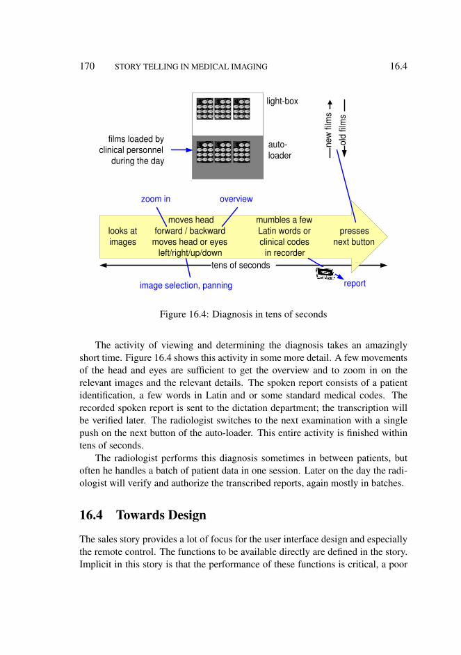
170 STORY TELLING IN MEDICAL IMAGING 16.4
tens of seconds
auto- loader
light-box
films loaded by clinical personnel
during the day
looks at images
moves head forward / backward
moves head or eyes left/right/up/down
zoom in overview
image selection, panning
mumbles a few Latin words or clinical codes
in recorder
presses next button
new
film
s
old
film
s
report
Figure 16.4: Diagnosis in tens of seconds
The activity of viewing and determining the diagnosis takes an amazinglyshort time. Figure 16.4 shows this activity in some more detail. A few movementsof the head and eyes are sufficient to get the overview and to zoom in on therelevant images and the relevant details. The spoken report consists of a patientidentification, a few words in Latin and or some standard medical codes. Therecorded spoken report is sent to the dictation department; the transcription willbe verified later. The radiologist switches to the next examination with a singlepush on the next button of the auto-loader. This entire activity is finished withintens of seconds.
The radiologist performs this diagnosis sometimes in between patients, butoften he handles a batch of patient data in one session. Later on the day the radi-ologist will verify and authorize the transcribed reports, again mostly in batches.
16.4 Towards Design
The sales story provides a lot of focus for the user interface design and especiallythe remote control. The functions to be available directly are defined in the story.Implicit in this story is that the performance of these functions is critical, a poor

16.4 TOWARDS DESIGN 171
performance would kill the sales. The performance was not specified explicitly.However the implied response times were 1 second for image retrieval and 0.1seconds for a contrast/brightness change. These requirements have a direct effecton the pipeline design and the user interface design.
sales story
20 1024 2 8 bit images 3 films of 4k*5k pixels
per examination 4 exams / room
3 rooms/workstation analyse design
memory budget CPU load
network load disk budget algorithms
analyse design
response time, minimal UI ease of use
C ustomer objectives
A pplication F unctional C onceptual R ealization
radiologist at work
film efficiency
processing throughput and quality
response times: image retrieve, C/B
RC functionality
pipeline design RC design
Figure 16.5: The stories in relation to the CAFCR views and the derived require-ments and design choices
Figure 16.5 shows the flow from both stories to requirements and design. Italso shows the inputs that went into the stories: at the commercial side the easeof use as sales feature and the film efficiency as the main application value. Thegain in film efficiency is 20% to 50% relative to the screen copy approach usedoriginally, or in other words the typical use of 3 to 5 film sheets is reduced to 2 to 3film sheets. These numbers are based on the typical case described in Section 14.3.
The a priori know-how that the response time in a software only solutionwould be difficult, makes this a challenging story. The technical challenge in thisstory is to achieve the desired image quality and throughput, also in the softwareonly solution.
The minimal user interface is also a design challenge. Without the sales storythe user interface provided would have been much too technical, an overwhelmingamount of technical possibilities would have been offered, without understandingthe clinical world view.
The story of the radiologist at work, in combination with the typical case,is the direct input for the throughput specification. The throughput specificationis used for the memory and disk budgets and the CPU and network loads. The
172 STORY TELLING IN MEDICAL IMAGING 16.5
image quality requirements, in combination with the loads and budgets, result inalgorithmic choices.
The original software completely ignored the need for printing images on film,it was not even present! The developer crew assumed that radiologists woulduse the workstation for “soft” diagnosis. Soft diagnosis is diagnosis from themonitor screen instead of film. A better understanding of the radiologist wasneeded to get the focus on the film printing functionality. The story immediatelyclarifies the importance of film sheets for diagnosis. The story also provides inputfor the functionality to create the layout of images and text on film. The auto-print functionality has been added in an extremely pragmatic way, by (mis-)usingexamination data fields to request printing. This pragmatic choice could only bejustified by the value of this function as was made clear in this story.
16.5 Conclusion
Stories have not been used explicitly in the case. Somewhat less specific oral sto-ries were provided by the marketing manager. Quantitative information was de-scribed in a typical case. The facts for quantification were provided by applicationmanagers. The presence of a quantified typical case provided the means for de-sign, analysis and testing. The lack of explicit story, in combination with the poorcoverage of the Customer Objectives and Application views as described in Chap-ter 14 in general, caused the late addition of the printing functionality.
Chapter 17
Threads of Reasoning in theMedical Imaging Case
17.1 Introduction
The thread of reasoning has not been applied consciously during the developmentof the Medical Imaging Workstation. This chapter describes a reconstruction ofthe reasoning as it has taken place. In Section 17.2 the outline of the thread isexplained. Section 17.3 describes the 5 phases as defined in Chapter 12:
1. Select starting point (17.3.1)
2. Create insight (17.3.2)
3. Deepen insight (17.3.3)
4. Broaden insight (17.3.4)
5. Define and extend the thread (17.3.5)
17.2 Example Thread
Figure 17.1 shows a set of interrelated customer objectives up to interrelated de-sign decisions. This set of interrelated objectives, specification issues and con-cepts is a dominant thread of reasoning in the development of the medical imagingworkstation.
The objectives of the radiologist are at the same time reenforcing and (some-what) conflicting. To achieve a good diagnostic quality sufficient time is required
173

174 THREADS OF REASONING IN THE MEDICAL IMAGING CASE 17.2
Concepts Customer objectives Specification issues
time efficient
diagnostic quality
safety (liability)
system response
system throughput
image quality
resource management processor, memory
internal logistics concurrency, processes
image processing algorithms
rein
forc
ing
conf
lictin
g
rein
forc
ing
conf
lictin
g
desi
gn
spac
e
C ustomer objectives
A pplication F unctional C onceptual R ealization
Figure 17.1: The thread of reasoning about the tension between time efficiency onthe one hand and diagnostic quality, safety, and liability on the other hand. In thedesign space this tension is reflected by many possible design trade-offs.
or examine and study the results, which can be in conflict with time efficiency.On the other hand a good diagnostic quality will limit discussions and repeatedexaminations later on, by which good diagnostic quality can help to achieve timeefficiency.
The customer objectives are translated into specifications. The diagnosticquality and safety/liability translate for example into image quality specifications(resolution, contrast, artefact level). A limited image quality is a primary sourceof a poor diagnostic quality. Artifacts can result in erroneous diagnostics, with itssafety and liability consequences.
The time efficiency is achieved by system throughput. The workstation shouldnot be the bottleneck in the total department flow or in the system response time.Waiting for results is clearly not time efficient.
Also at the specification level the reenforcing and the conflicting requirementsare present. If the image quality is good, no tricky additional functions are neededto achieve the diagnostic quality. For instance if the image has a good clinicalcontrast to noise ratio, then no artificial contrast enhancements have to be applied.Function bloating is a primary source of decreased throughput and increased re-sponse times. The conflicting aspect is that some image quality functions areinherently time consuming and threaten the throughput and response time.
17.3 EXPLORATION OF PROBLEMS AND SOLUTIONS 175
The design space is full of concepts, where design choices are needed. Theconcepts of resource management, internal logistics and image processing algo-rithms have a large impact on the system response time and throughput. The imageprocessing algorithms determine the resulting image quality.
The design space is not a simple multi-dimensional space, with orthogonal,independent dimensions. The image processing algorithm has impact on the CPUusage, cache efficiency, memory usage, and image quality. The implementationof these algorithms can be optimized to one or two of these entities, often at thecost of the remaining optimization criteria. For instance: images can be storedcompletely in memory, which is most efficient for CPU processing time. An al-ternative is to store and process small parts of the image (lines) at a time, whichis more flexible with respect to memory (less fragmentation), but the additionalindirection of addressing the image line costs CPU time.
Adding concurrency partially helps to improve response times. Waiting times,for instance for disk reads, can then be used to do other useful processing. On theother hand additional overhead in context switching, and locking is caused by theconcurrency.
The essence of the thread of reasoning is to have sufficient insight in the cus-tomer and application needs, so that the problem space becomes sharply definedand understood. This understanding is used to select the sweet spots of the de-sign space, that satisfy the needs. Understanding of the design space is needed tosharpen the understanding of the problem space; in other words iteration betweenproblem and solution space is required.
17.3 Exploration of Problems and Solutions
In this section the thread of reasoning is shown as it emerges over time. For everyphase the CAFCR views are annotated with relevant subjects in that phase and therelations between the subjects.
Figures 17.2 to 17.6, described in Subsections 17.3.1 to 17.3.5, show thephases as described in Chapter 12. The figures show the main issues under dis-cussion as dots. The relations between the issues are shown as lines between theissues, where the thickness of the line indicates the relative weight of the relation-ship. The core of the reasoning is indicated as a thick arrow. The cluster of issuesat the start point and at the finish are shown as letter in a white ellipse. Someclusters of issues at turning points in the reasoning are also indicated as whiteellipse.
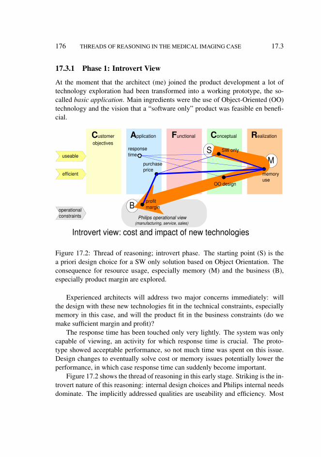
176 THREADS OF REASONING IN THE MEDICAL IMAGING CASE 17.3
17.3.1 Phase 1: Introvert View
At the moment that the architect (me) joined the product development a lot oftechnology exploration had been transformed into a working prototype, the so-called basic application. Main ingredients were the use of Object-Oriented (OO)technology and the vision that a “software only” product was feasible en benefi-cial.
Philips operational view (manufacturing, service, sales)
C onceptual
S
C ustomer objectives
A pplication F unctional R ealization
purchase price
response time
Introvert view: cost and impact of new technologies
useable
efficient
operational constraints
M
B profit margin
SW only
memory use
OO design
Figure 17.2: Thread of reasoning; introvert phase. The starting point (S) is thea priori design choice for a SW only solution based on Object Orientation. Theconsequence for resource usage, especially memory (M) and the business (B),especially product margin are explored.
Experienced architects will address two major concerns immediately: willthe design with these new technologies fit in the technical constraints, especiallymemory in this case, and will the product fit in the business constraints (do wemake sufficient margin and profit)?
The response time has been touched only very lightly. The system was onlycapable of viewing, an activity for which response time is crucial. The proto-type showed acceptable performance, so not much time was spent on this issue.Design changes to eventually solve cost or memory issues potentially lower theperformance, in which case response time can suddenly become important.
Figure 17.2 shows the thread of reasoning in this early stage. Striking is the in-trovert nature of this reasoning: internal design choices and Philips internal needsdominate. The implicitly addressed qualities are useability and efficiency. Most
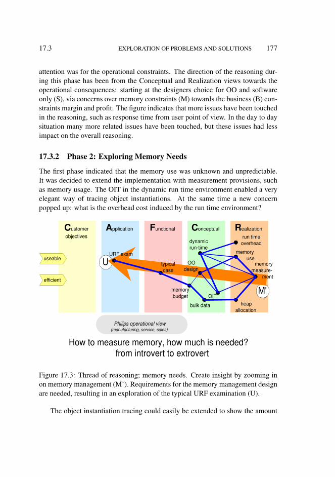
17.3 EXPLORATION OF PROBLEMS AND SOLUTIONS 177
attention was for the operational constraints. The direction of the reasoning dur-ing this phase has been from the Conceptual and Realization views towards theoperational consequences: starting at the designers choice for OO and softwareonly (S), via concerns over memory constraints (M) towards the business (B) con-straints margin and profit. The figure indicates that more issues have been touchedin the reasoning, such as response time from user point of view. In the day to daysituation many more related issues have been touched, but these issues had lessimpact on the overall reasoning.
17.3.2 Phase 2: Exploring Memory Needs
The first phase indicated that the memory use was unknown and unpredictable.It was decided to extend the implementation with measurement provisions, suchas memory usage. The OIT in the dynamic run time environment enabled a veryelegant way of tracing object instantiations. At the same time a new concernpopped up: what is the overhead cost induced by the run time environment?
Philips operational view (manufacturing, service, sales)
A pplication R ealization
M'
U
F unctional C onceptual C ustomer objectives
URF exam memory use
OO design
dynamic run-time
run time overhead
OIT
memory measure-
ment
heap allocation
typical case
bulk data
How to measure memory, how much is needed? from introvert to extrovert
memory budget
useable
efficient
Figure 17.3: Thread of reasoning; memory needs. Create insight by zooming inon memory management (M’). Requirements for the memory management designare needed, resulting in an exploration of the typical URF examination (U).
The object instantiation tracing could easily be extended to show the amount

178 THREADS OF REASONING IN THE MEDICAL IMAGING CASE 17.3
of memory allocated for the object structures. The large data elements, such asimages, are allocated on the heap and required additional instrumentation. Viathe bulkdata concept this type of memory use was instrumented. Bottom up theinsight in memory use was emerging.
The need arose to define relevant cases to be measured and to be used as thebasis for a memory budget. An URF examination was used to define a typicalcase. Now the application knowledge starts to enter the reasoning process, andthe reasoning starts to become more extrovert. Efficiency and usability are themain qualities addressed.
Figure 17.3 shows the thread of reasoning for Phase 2. The reasoning is stillbottom-up from Realization towards Application View. The realization concernsabout speed and memory consumption (M’) result into concepts for resource man-agement and measurement support. For analysis and validation a use case descrip-tion in the Functional view is needed. The use case is based on insight in a URFexamination (U) from application viewpoint.
17.3.3 Phase 3: Extrovert View Uncovers Gaps in Conceptual andRealization Views
The discussion about the URF examination and the typical case made it very clearthat radiologists perform their diagnoses by looking at the film on the lightbox.This is for them very efficient in time. Their speed of working is further increasedby the autoloader, which quickly shows all films of the next examination.
To support this typical workflow the production of filmsheets and the through-put of films and examinations is important. Interactive viewing on the other handis from the radiologist’s point of view much less efficient. Diagnosis on the basisof film takes seconds, diagnosis by interactive viewing takes minutes. The auto-print functionality enables the production of films directly from the examinationroom.
auto-print functionality requires lots of new functions and concepts in the sys-tem, such as background printing (spooling), defining and using film layouts,using the right rendering, et cetera. The processing library must support thesefunctions. Also an execution architecture is required to support the concurrency:server processes and spool processes are introduced. Last but not least, hardcopyunits (HCU), for example laser printers, need to be interfaced to the system. Anew set of components is introduced in the system to do the printing: hardcopyinterface hardware, hardcopy driver, and the hardcopy units themselves.
During this phase the focus shifted from efficiency to effectiveness. Efficiency
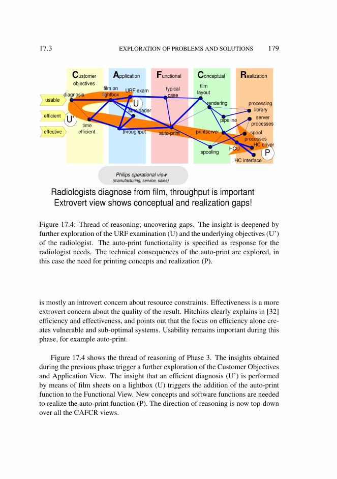
17.3 EXPLORATION OF PROBLEMS AND SOLUTIONS 179
C ustomer objectives
A pplication R ealization
U
U'
P
F unctional C onceptual
diagnosis film on lightbox
time efficient throughput auto-print
film layout
spooling
rendering processing library
spool processes
HC interface
HC driver
autoloader server
processes
HCU
printserver
pipeline
URF exam typical case
Radiologists diagnose from film, throughput is important Extrovert view shows conceptual and realization gaps!
usable
efficient
effective
Philips operational view (manufacturing, service, sales)
Figure 17.4: Thread of reasoning; uncovering gaps. The insight is deepened byfurther exploration of the URF examination (U) and the underlying objectives (U’)of the radiologist. The auto-print functionality is specified as response for theradiologist needs. The technical consequences of the auto-print are explored, inthis case the need for printing concepts and realization (P).
is mostly an introvert concern about resource constraints. Effectiveness is a moreextrovert concern about the quality of the result. Hitchins clearly explains in [32]efficiency and effectiveness, and points out that the focus on efficiency alone cre-ates vulnerable and sub-optimal systems. Usability remains important during thisphase, for example auto-print.
Figure 17.4 shows the thread of reasoning of Phase 3. The insights obtainedduring the previous phase trigger a further exploration of the Customer Objectivesand Application View. The insight that an efficient diagnosis (U’) is performedby means of film sheets on a lightbox (U) triggers the addition of the auto-printfunction to the Functional View. New concepts and software functions are neededto realize the auto-print function (P). The direction of reasoning is now top-downover all the CAFCR views.
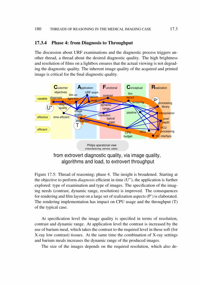
180 THREADS OF REASONING IN THE MEDICAL IMAGING CASE 17.3
17.3.4 Phase 4: from Diagnosis to Throughput
The discussion about URF examinations and the diagnostic process triggers an-other thread, a thread about the desired diagnostic quality. The high brightnessand resolution of films on a lightbox ensures that the actual viewing is not degrad-ing the diagnostic quality. The inherent image quality of the acquired and printedimage is critical for the final diagnostic quality.
R ealization C ustomer objectives
A pplication
U" P'
T
C onceptual F unctional
diagnosis film on
light-box
time efficient throughput
film layout
rendering processing library
HC interface HCU
URF exam
from extrovert diagnostic quality, via image quality, algorithms and load, to extrovert throughput
diagnostic quality
image quality
contrast
dynamic range
resolution
HCU processing
pixel depth
interpolation
barium meal
pipeline
CPU budget
typical case
useable
efficient
effective
Philips operational view (manufacturing, service, sales)
Figure 17.5: Thread of reasoning; phase 4. The insight is broadened. Starting atthe objective to perform diagnosis efficient in time (U”), the application is furtherexplored: type of examination and type of images. The specification of the imag-ing needs (contrast, dynamic range, resolution) is improved. The consequencesfor rendering and film layout on a large set of realization aspects (P’) is elaborated.The rendering implementation has impact on CPU usage and the throughput (T)of the typical case.
At specification level the image quality is specified in terms of resolution,contrast and dynamic range. At application level the contrast is increased by theuse of barium meal, which takes the contrast to the required level in these soft (forX-ray low contrast) tissues. At the same time the combination of X-ray settingsand barium meals increases the dynamic range of the produced images.
The size of the images depends on the required resolution, which also de-

17.3 EXPLORATION OF PROBLEMS AND SOLUTIONS 181
termines the film layout. The rendering algorithms must fulfil the image qualityspecifications. The rendering is implemented as a pipeline of processing stepsfrom an optimized processing library.
One of the costly operations is the interpolation. One of the design optionswas to use the processing in the hardcopy unit. This would greatly relieve theresource (processor and memory) needs, but it would at the same time be muchless flexible with respect to rendering. It was decided not to use the hardcopy unitprocessing.
A CPU budget was created, based on the typical case and taking into accountall previous design know-how. This CPU budget did fit in the required throughputneeds.
Usability, effectiveness and efficiency are more or less balanced at this mo-ment.
Figure 17.5 shows the thread of reasoning for Phase 4. During this phasethe reasoning iterates over all the CAFCR views. The diagnostic quality (U”)in the Customer Objectives View results via the clinical acquisition methods inthe Application view in image quality requirements in the Functional View. Thelayout and rendering in the Conceptual view result in a large set of processingfunctions (P’) in the Realization view. The specific know how of the processing inthe Realization is used for the CPU and memory budgets in the conceptual view,to validate the feasibility of supporting the typical case in the Functional view.The typical case is a translation of the throughput (T) needs in the ApplicationView.
17.3.5 Phase 5: Cost Revisited
At this moment much more information was available about the relation betweenresource needs and system performance. The business policy was to use standardof-the-shelf workstations. The purchase price by the customer could only be metby using the lowest cost version of the workstation. Another policy was to usea Philips medical console, which was to be common among all products. Thisconsole was about half of the material cost of the Medical Imaging workstation.
The real customer interest is to have a system that is economically sound, andwhere throughput and cost of ownership (CoO) are balanced. Of course the mainclinical function, diagnosis, must not suffer from cost optimizations. A detailedand deep understanding of the image quality needs of the customer is needed tomake an optimized design.
Note that at this moment in time many of the considerations discussed in the

182 THREADS OF REASONING IN THE MEDICAL IMAGING CASE 17.4
Philips operational view (manufacturing, service, sales)
C onceptual
efficient
useable
R ealization C ustomer objectives
A pplication F unctional
diagnosis
time efficient throughput processing
library
cost revisited in context of clinical needs and realization constraints; note: original threads are significantly simplified
diagnostic quality
image quality IQ spec
pixel depth
CPU budget
typical case
common console
memory limit
BoM Moore's
law
purchase price
CoO economic
sound
render engine
effective
operational constraints
M'
S
M
B
U"
P'
T
U
U' P
profit margin standard workstation
C
memory budget
Figure 17.6: Thread of reasoning; cost revisited. The entire scope of the threadof reasoning is now visible. Sufficient insight is obtained to return to the originalbusiness concern of margin and cost (C). In the mean time additional assumptionshave surfaced: a common console and standard workstation to reduce costs. Fromthis starting point all other viewpoints are revisited: via time efficient diagnosis toimage quality to rendering and processing and back to the memory design.
previous steps are still valid and present. However Figure 17.6 is simplified byleaving out many of these considerations.
Besides efficiency, effectiveness, and usability, the operational constraint isback in the main reasoning thread. At this moment in time that makes a lot ofsense, because problem and solution space are sufficiently understood. These con-straints never disappeared completely, but the other qualities were more dominantin the intermediate phases.
Figure 17.6 shows the thread of reasoning in Phase 5. The original businessviewpoint is revisited: do we have a commercial feasible product? A full iterationover all CAFCR views relates product costs (C) to the key drivers in the CustomerObjectives. The main tensions in the product specification are balanced: imagequality, throughput of the typical case and product cost. To do this balancing themain design choices in the Conceptual and Realization views have to be reviewed.

17.4 CONCLUSION 183
17.4 Conclusion
Philips operational view (manufacturing, service, sales)
efficient
useable
R ealization C onceptual C ustomer objectives
A pplication F unctional
effective
operational constraints
M'
S M
B
U"
P'
T
U U'
P
C
phase 1 phase 2 phase 3 phase 4 phase 5
legend
Figure 17.7: All steps superimposed in one diagram. The iterative nature of thereasoning is visible: the same aspects are explored multiple times, coming fromdifferent directions. It also shows that jumps are made during the reasoning.
The know-how at the start of the product creation was limited to a numberof nice technology options and a number of business and application opportuni-ties. The designers had the technology know-how, the marketing and applicationmanagers had the customer know-how. The product creation team went throughseveral learning phases. Figure 17.7 shows the many iterations in the five phases.During those phases some of the know-how was shared and a lot of new know-how emerged. The sharing of know-how made it possible to relate customer needsto design and implementation options. The interaction between the team membersand the search for relations between needs and designs triggered many new ques-tions. The answers to these questions created new know-how.
The architecting process has been analyzed in retrospect, resulting in this de-scription of threads of reasoning. This Chapter Threads of Reasoning shows that:
• The specification and design issues that are discussed fit in all CAFCRviews or the operational view.

184 THREADS OF REASONING IN THE MEDICAL IMAGING CASE 17.4
• The positioning of the issues and their relationships in the CAFCR viewsenable a compact description of the reasoning during the product creation.
• Submethods are used to address one issue or a small cluster of issues.• Qualities are useful as integrating elements over the CAFCR views.• The threads of reasoning are an explicit way to facilitate the interaction and
the search for relations.• The threads of reasoning create an integral overview.• The threads of reasoning facilitate a converging specification and design.

Part IV
Evaluation, Discussion andConclusions
Chapters in Part IV:
18. Evaluation of the Architecting Method
19. Evaluation from aWider Context
20. Balancing Genericity and Specificity
21. Reflection on Research Method to Study Architecting Methods
22. The Future of Architecting Research
23. Conclusion
185

Chapter 18
Evaluation of the ArchitectingMethod
18.1 Introduction
The hypothesis formulated in Chapter 6 is evaluated by means of the MedicalImaging Workstation case. This evaluation uses the criteria that have been definedin Chapter 6.
Figure 18.1 shows how the case maps on the hypothesis and repeats the crite-ria. This figure is used as the basis for the evaluation of the case.
The hypothesis narrows the scope: the method is applied on software and tech-nology intensive complex systems and the product creation takes place in hetero-geneous environments. The medical imaging workstation fully fits in these con-straints. The system requires many hardware and software technologies, see Fig-ure 3.5 and the list of technology innovations in Section 3.2. Also a lot of physicsand clinical application related technologies are required to translate pixels intoclinically relevant information. The heterogeneity of the environment is present inmultiple dimensions: modalities (X-ray, CT, MRI), applications (gastro-intestinal,vascular, CT and many more) and releases (URF, vascular, CT, and MRI; each ofthem interoperable with multiple releases).
Section 18.2 evaluates the design of the product. The design quality is a mea-sure for the sustainability of the product and for the support of the method tothe PCP team. Section 18.3 evaluates the product itself. The product evaluationaddresses the criteria 1 and 2, of Figure 18.1, which address the commercial suc-cess. Section 18.4 discusses how the method has been instrumental in creating the
187

188 EVALUATION OF THE ARCHITECTING METHOD 18.2
criteria 1. product is a commercial success 2. product family is sustainable commercially successful 3. architects benefit from deploying submethods in multi-view framework 4. project leaders, product managers and engineers are able to use
the outcome of the submethods
hypothesis
A rich collection of submethods fitting in a multi-view framework
complemented with reasoning methods enables successful architecting of technology
and software intensive complex systems in heterogeneous environments by means of
generic insights grounded in specific facts
CAFCR submethods qualities checklists
story telling CAFCR
quality needles threads of reasoning
medical imaging
workstation
multi-modality multi-application
multi-release small system level
specifications measurements,
source code, log files films, images, et cetera
Figure 18.1: Annotated hypothesis and criteria as basis for the evaluation
product and how it has contributed to sustainable success, thus evaluating crite-rion 3: Criterion 4, the usability of the outcome, is evaluated in Section 18.5. Theconclusion of the complete evaluation is articulated in Section 18.6.
18.2 Design Evaluation
Figure 18.2 shows an evaluation of the design quality, which is based on an inter-nal technology improvement plan [50].
The community of designers was very content about many of the concepts andimplementations. This assessment is rather subjective, because the designers arecreators and users of the design at the same time. The following three questionsare a somewhat more objective way to make the quality assessment more explicit:
• Does the product, based on this design, fulfill the requirements?• How does the design support ongoing developments? How is development
effort (in time and manpower) affected when new functionality is added, forinstance as shown in Figure 14.10?
• Benchmarking: How does the product and design compare with other prod-ucts? For example, compare code size in relation to the offered functionality
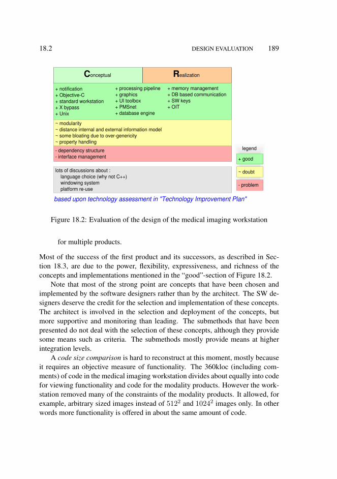
18.2 DESIGN EVALUATION 189
C onceptual R ealization
+ notification + Objective-C + standard workstation + X bypass + Unix
- dependency structure - interface management
~ modularity ~ distance internal and external information model ~ some bloating due to over-genericity ~ property handling
lots of discussions about : language choice (why not C++) windowing system platform re-use
+ processing pipeline + graphics + UI toolbox + PMSnet + database engine
+ memory management + DB based communication + SW keys + OIT
- problem
~ doubt
+ good
based upon technology assessment in "Technology Improvement Plan"
legend
Figure 18.2: Evaluation of the design of the medical imaging workstation
for multiple products.
Most of the success of the first product and its successors, as described in Sec-tion 18.3, are due to the power, flexibility, expressiveness, and richness of theconcepts and implementations mentioned in the “good”-section of Figure 18.2.
Note that most of the strong point are concepts that have been chosen andimplemented by the software designers rather than by the architect. The SW de-signers deserve the credit for the selection and implementation of these concepts.The architect is involved in the selection and deployment of the concepts, butmore supportive and monitoring than leading. The submethods that have beenpresented do not deal with the selection of these concepts, although they providesome means such as criteria. The submethods mostly provide means at higherintegration levels.
A code size comparison is hard to reconstruct at this moment, mostly becauseit requires an objective measure of functionality. The 360kloc (including com-ments) of code in the medical imaging workstation divides about equally into codefor viewing functionality and code for the modality products. However the work-station removed many of the constraints of the modality products. It allowed, forexample, arbitrary sized images instead of 5122 and 10242 images only. In otherwords more functionality is offered in about the same amount of code.
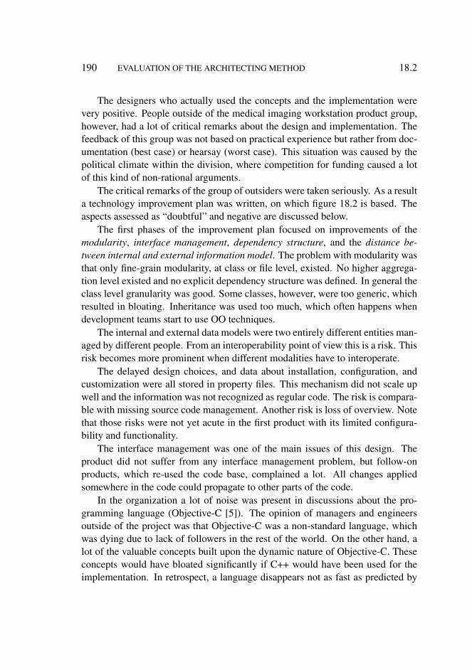
190 EVALUATION OF THE ARCHITECTING METHOD 18.2
The designers who actually used the concepts and the implementation werevery positive. People outside of the medical imaging workstation product group,however, had a lot of critical remarks about the design and implementation. Thefeedback of this group was not based on practical experience but rather from doc-umentation (best case) or hearsay (worst case). This situation was caused by thepolitical climate within the division, where competition for funding caused a lotof this kind of non-rational arguments.
The critical remarks of the group of outsiders were taken seriously. As a resulta technology improvement plan was written, on which figure 18.2 is based. Theaspects assessed as “doubtful” and negative are discussed below.
The first phases of the improvement plan focused on improvements of themodularity, interface management, dependency structure, and the distance be-tween internal and external information model. The problem with modularity wasthat only fine-grain modularity, at class or file level, existed. No higher aggrega-tion level existed and no explicit dependency structure was defined. In general theclass level granularity was good. Some classes, however, were too generic, whichresulted in bloating. Inheritance was used too much, which often happens whendevelopment teams start to use OO techniques.
The internal and external data models were two entirely different entities man-aged by different people. From an interoperability point of view this is a risk. Thisrisk becomes more prominent when different modalities have to interoperate.
The delayed design choices, and data about installation, configuration, andcustomization were all stored in property files. This mechanism did not scale upwell and the information was not recognized as regular code. The risk is compara-ble with missing source code management. Another risk is loss of overview. Notethat those risks were not yet acute in the first product with its limited configura-bility and functionality.
The interface management was one of the main issues of this design. Theproduct did not suffer from any interface management problem, but follow-onproducts, which re-used the code base, complained a lot. All changes appliedsomewhere in the code could propagate to other parts of the code.
In the organization a lot of noise was present in discussions about the pro-gramming language (Objective-C [5]). The opinion of managers and engineersoutside of the project was that Objective-C was a non-standard language, whichwas dying due to lack of followers in the rest of the world. On the other hand, alot of the valuable concepts built upon the dynamic nature of Objective-C. Theseconcepts would have bloated significantly if C++ would have been used for theimplementation. In retrospect, a language disappears not as fast as predicted by

18.3 PRODUCT EVALUATION 191
many of its opponents. Somewhat less heated was the debate about the windowingsystem. Most organizational noise was removed by the use of the X-compatiblebypass (Nix).
A lot of disturbance was caused by the platform expectations in the organiza-tion. The original objective of the development team [52] was to create a re-usableplatform for Philips Medical Systems. The team focus changed to create medi-cal imaging workstation products. From the product management point of viewthe platform creation became a non-issue: platforms are not sold to external cus-tomers! The product groups in the context did not follow this focus change. Theyexpected a cost reduction to be achieved by sharing the development costs of aviewing platform.
18.3 Product Evaluation
The case describes the development of the first product release of the MedicalImaging Workstation. Figure 18.3 shows the strong and weak points, as they wereperceived at the outside of the product.
operational feedback
customer feedback
C ustomer objectives
A pplication F unctional
++ usability film layout ++ film efficiency + operator efficiency printing + ease of auto-printing
- concurrent viewing and auto-printing
+ throughput + image quality + interoperability URF
- interoperability vascular
+ sales volume + selling price + margin + time to market
+ manufacturability + option handling
~ network installation - return on investment - problem
~ doubt
+ good or ++ very good
legend
Figure 18.3: Evaluation of the medical imaging workstation product
The feedback from the URF customers, obtained via application managerswho visit many URF departments, was very positive about the usability of the filmlayout and the film efficiency. Also the operator efficiency of printing and ease ofauto-printing was appreciated. Viewing was used only very limited. The few userswho used it also for viewing complained about the simultaneous performance of

192 EVALUATION OF THE ARCHITECTING METHOD 18.3
viewing and auto-printing. Note that this was no surprise; it was even according tospecification. It indicates that to a small subset of the customers the specificationwas insufficient.
At specification level the throughput, image quality, and interoperability withURF systems were according to specification. The specification is appreciatedby the customer. The interoperability with vascular systems was below internal(product management) expectations. Product management expected vascular sys-tems to interoperate in the same way as URF systems. However, vascular systemsare used quite differently than URF systems. The functionality and performanceneeds of vascular surgeons differ from the radiologist’s needs. The system didnot provide significant value for vascular use. The vascular product group did nothave a clear incentive to improve the interoperability, because of the lack of addedvalue, Not many customer complaints were filed about this problem1.
From a business point of view the product was clearly a success. It yielded agood sales volume (increasing from circa 50 systems in the first year to hundredsof systems in later years), the right selling price, a reasonable margin, and a goodtime to market. The return on investment (ROI)2, however, only occurred afterseveral years.
At the portfolio level of Philips Medical Systems (PMS) the turnover of theseworkstations was negligible. Modality systems (MRI, X-ray, CT-scanners) formthe bulk of the turnover. Modality systems have a limited innovation speed, dueto their multi-technology complexity and their safety requirements. The medicalimaging workstation provided a means to introduce image handling innovationfaster, because this product has its own (more dynamic) life-cycle. In later yearsthe strategic value of an independent platform for image handling innovation atPMS level turned out to be large. Additional modality3 turnover could be realizedthanks to the image handling capabilities of the medical imaging workstation.
Feedback from manufacturing and service departments indicates that the op-erational requirements, such as manufacturability and option handling, were ful-filled satisfactorily. Installation of networking functionality overlapped with other
1Service engineers and application managers file complaints of users by means of Problem Re-ports. A control board analyses and discusses incoming Problem Reports regularly.
2 Product groups have a profit/loss responsibility. Losses are accepted for about 2 years, aftersuch a start-up period a “normal” ROI is demanded. The volume of all products, including options,was after about 2 years at an acceptable level. Especially the (software) options helped to get at anacceptable ROI.
3The term modality system is used for image acquisition systems. The image acquisition tech-nique, such as MR, CT, US, or X-ray, is dominant in the system design. This technique is called themodality.
18.4 EVALUATION OF ARCHITECTING METHOD 193
hospital disciplines, such as IT departments and facility management. For thePhilips service work force this was a new area. The networking was not a bigissue, but it required quite a lot operational attention.
18.4 Evaluation of Architecting Method
Subsection 18.4.1 evaluates the use of the submethods, described in the Chapters 8and 9 and applied in the Chapters 14 and 15. The use of the qualities and the qual-ity checklist (Chapter 10) are evaluated in Subsection 18.4.2. Subsection 18.4.3evaluates the story telling (Chapter 11 and 16). The reasoning methods (describedin Chapter 12 and applied in Chapter 17) are evaluated in Subsection 18.4.4. Theintegration of all components of the methods is evaluated in Subsection 18.4.5.
18.4.1 CAFCR Submethods
Figure 18.4 shows the submethods per view. Every method is annotated withits usage in the case. Many submethods are used explicitly, although not alwaysexactly as described in part II. The fact that these submethods have been usedrecognizes the need for these methods.
Some subjects covered by submethods have been discussed during the productcreation, but did not result in any specific consolidation of data in specifications.In figure 18.4 these submethods are labelled “only implicitly”. Often the coverageof these subjects was rather partial. They have been discussed, but they were notthoroughly analyzed.
The fact, for instance, that safety has not been explicitly addressed in the firstrelease is due to the low severity factor of this product. This product does notimmediately endanger patients or operators. X-ray systems, on the other hand,use radiation and heavy moving parts that can be dangerous for patients as well aspersonnel. These systems take measures to cope with the risks, such as shieldingand detection. In later releases of the medical imaging workstation the safety hasbeen addressed explicitly, with a mandatory hazard analysis and accompanyingspecification and design measures.
The subjects that have not been covered in the first release were less impor-tant and critical than the covered subjects. This selection process is described inFigure 7.7. Some of these subjects, for instance security, have been addressedexplicitly in a later release.
The most remarkable observation from Figure 18.4 is that the Customer Ob-jectives and Application views are poorly covered. As discussed in Section 17.3

194 EVALUATION OF THE ARCHITECTING METHOD 18.4
C ustomer objectives
A pplication F unctional C onceptual R ealization
key drivers value chain
business models suppliers
c ontext diagram
stakeholders and concerns
entity relationship models
dynamic models
c ase descriptions commercial
decomposition service
decomposition goods flow
decomposition function and
feature specifications
performance external interfaces standards
construction decomposition
functional decomposition
designing with multiple decompositions
execution architecture
internal interfaces performance start up shutdown integration plan
work breakdown safety
reliability security
budget benchmarking performance
analysis granularity
determination
value and cost
safety analysis reliability analysis security analysis
explicitly addressed addressed only implicitly not addressed
coverage based on documentation status of first product release
legend
Figure 18.4: Coverage of submethods discussed in part II
the introvert culture of the development teams causes this unbalance.
18.4.2 Qualities
Figure 18.5 shows the use of qualities that appear in in the documentation struc-ture in 1996, when the product family was already more mature. A significantamount of qualities were explicitly documented in separate documents: imagequality, safety, security, throughput or productivity, connectivity, resource utiliza-tion, configurability and installability. Many other qualities were addressed aspart of other documentation, such as functional requirement specifications or thetechnical product documentation.
Figure 18.6 shows the relative coverage of the qualities as they have beenapplied in the case. This coverage is determined by the amount of explicit andimplicit information present in the system documentation, see Figure 18.5. Therelative relevance of these qualities for this business is also shown. The relevance
18.4 EVALUATION OF ARCHITECTING METHOD 195
usability attractiveness responsiveness image quality wearability storability transportability
usable
safety security reliability robustness integrity
reliable
throughput or productivity
effective
serviceability configurability installability
serviceable
liability testability traceability standards compliance
liable
ecological footprint contamination noise disposability
ecological
reproducibility predictability
consistent
efficient resource utilisation cost of ownership
cost price power consumption consumption rate
(water, air, chemicals, et cetera)
size, weight accuracy
down to earth attributes
manufacturability logistics flexibility lead time
logistics friendly
evolvability portability upgradeability extendibility maintainability
future proof
interoperable connectivity 3 rd party extendible
implicit in other documents in separate document
legend
Figure 18.5: Quality documentation in 1996
is based on experience used in a retrospective assessment. The qualities in thisfigure have been aggregated. This aggregated format makes it immediately clearthat only a subset of qualities is relevant per business.
For medical imaging qualities such as ecological, logistics friendly and downto earth attributes are relatively unimportant. In other systems, for instance print-ers, all of these qualities are important.
The conclusion of Figures 18.6 and 18.5 is that the qualities play an impor-tant role in the product creation. For in this product many qualities were evendocumented in separate documents.
18.4.3 Story Telling
Story telling has not been deployed in the medical imaging case in the way de-scribed in in Chapter 11. In the documentation of the system there is a documentcalled typical case. This document partially fulfilled this role. The typical casein combination with the oral version, described in Chapter 16, proved to be veryvaluable to connect the clinical world and the engineering world. The radiologiststory created the focus on printing on film. The efficient film production becamethe number one selling argument of the product.

196 EVALUATION OF THE ARCHITECTING METHOD 18.4
Eco
logi
cal
Usa
ble
Rel
iabl
e
Effe
ctiv
e
Inte
rope
rabl
e
Effi
cien
t
Liab
le
Con
sist
ent
Ser
vice
able
Futu
re p
roof
Logi
stic
s fri
endl
y
Dow
n to
ear
th a
ttrib
utes
coverage
relevance
coverage based on amounf of explicit and implicit availbale information in documentation; relevance based on retrospective experience based assessment
completely covered
not covered
very relevant
not relevant
legend
Figure 18.6: Coverage profile of qualities
18.4.4 Threads of Reasoning
The threads of reasoning were only semi-consciously applied. The fast iterationover multiple views was consciously applied. The integral understanding emergedas a result of this fast iteration. In retrospect this approach can be visualized as athread of reasoning as described in Chapter 17. It is this integral understandingthat helped to finish the product within the constraints. The integral understandingcan indirectly be observed by the handling of the problems found during integra-tion, see Sections 13.4 and 13.5.
The introduction date is a very important business constraint: late introductionmeans lower market share and lower margins. The integral understanding madeit possible to finish the product in time. Without integral understanding it wouldhave taken much more time (months or years) to get the product at an acceptablelevel.
18.4.5 The Integration of the Method
The hypothesis starts with “A rich collection of submethods fitting in a multi-viewframework complemented with reasoning methods”. In other words the submeth-

18.4 EVALUATION OF ARCHITECTING METHOD 197
ods, the multi-view framework and the reasoning methods must be employablein a complementary fashion. The integration of components of the methods isevaluated in this subsection.
The main value provided by the architecting method is in detecting and solvingintegral problems, such as the throughput, image quality, and memory utilization.Most local aspects (single concepts, single functions) were engineered in a pro-fessional way. Integration problems arise across the boundaries of concepts andfunctions, and emerge due to the dynamic behavior of many components. Thesubmethods and the framework add means to do the system level design.
Many submethods are based on very specific and detailed facts. The typicalcase, as described in Section 14.3, also focuses on a completely quantified de-scription, which enables specific analysis and design actions. The specificationsat the system level have to be rather generic to keep the specifications usable andthe size manageable. Typical quality specifications, for instance, were between 4and 8 pages of content. In other words, in the consolidation of the design there isvery limited room for specific details.
The architect continuously operates in this field of force: the need for gener-icity in guidelines and rules, while the added value is mostly in the integral under-standing emerging from a large amount of highly specific detailed facts.
In the medical imaging workstation case the amount of viewpoints, submeth-ods, and qualities used was good: no dramatic problems caused by missing view-points, submethods or qualities arose later. All of the viewpoints, submethods,and qualities are highly relevant in solving the integration problems. The durationof the integration of the first product and of the later products, see Figure 14.10,was manageable. The relevance of the viewpoints, submethods, and qualities isshown in Chapter 17. The amount of method components was manageable for thearchitects, and the results could be absorbed by the stakeholders. The selectionof the methods emerged by (unconsciously) applying the threads of reasoning.Conclusion: the reasoning method resulted in a minimal set of required compo-nents of the method, and the reasoning method supported the integration of thesecomponents.
The balance between genericity and specificity, which is formulated at the endof the hypothesis “by means of generic insights grounded in specific facts”, didwork out well in the case. Sufficient specific details, such as measurements, sourcecode, log files, films, and images, were touched to form the basis for the emergingunderstanding. The size of the system level documentation was rather limited; theintegral overview was clearly present in the documentation, the overview was nothidden in a vast amount of details. Some of the engineers, however, criticized the
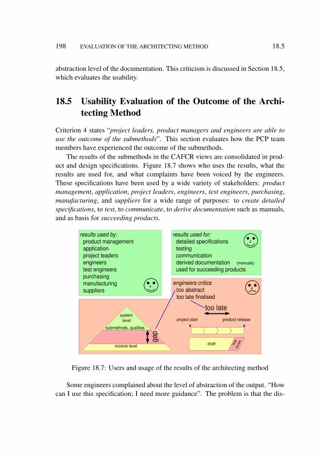
198 EVALUATION OF THE ARCHITECTING METHOD 18.5
abstraction level of the documentation. This criticism is discussed in Section 18.5,which evaluates the usability.
18.5 Usability Evaluation of the Outcome of the Archi-tecting Method
Criterion 4 states “project leaders, product managers and engineers are able touse the outcome of the submethods”. This section evaluates how the PCP teammembers have experienced the outcome of the submethods.
The results of the submethods in the CAFCR views are consolidated in prod-uct and design specifications. Figure 18.7 shows who uses the results, what theresults are used for, and what complaints have been voiced by the engineers.These specifications have been used by a wide variety of stakeholders: productmanagement, application, project leaders, engineers, test engineers, purchasing,manufacturing, and suppliers for a wide range of purposes: to create detailedspecifications, to test, to communicate, to derive documentation such as manuals,and as basis for succeeding products.
results used by: product management application project leaders engineers test engineers purchasing manufacturing suppliers
results used for: detailed specifications testing communication derived documentation (manuals)
used for succeeding products
system level
module level
submethods, qualities
gap
engineers critics too abstract too late finalised
too late project start product release
draft final
re
view
Figure 18.7: Users and usage of the results of the architecting method
Some engineers complained about the level of abstraction of the output. “Howcan I use this specification; I need more guidance”. The problem is that the dis-
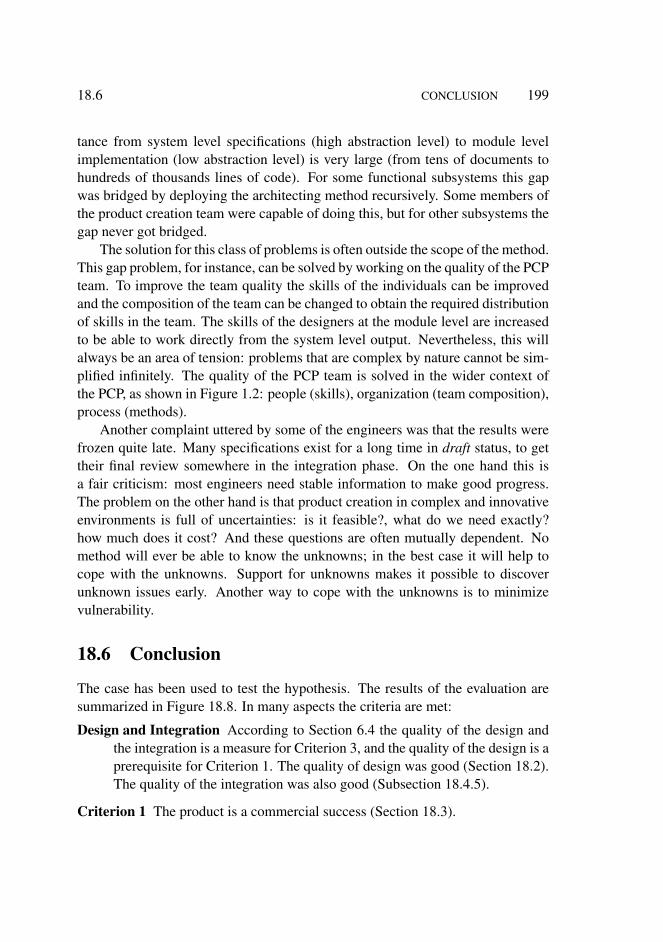
18.6 CONCLUSION 199
tance from system level specifications (high abstraction level) to module levelimplementation (low abstraction level) is very large (from tens of documents tohundreds of thousands lines of code). For some functional subsystems this gapwas bridged by deploying the architecting method recursively. Some members ofthe product creation team were capable of doing this, but for other subsystems thegap never got bridged.
The solution for this class of problems is often outside the scope of the method.This gap problem, for instance, can be solved by working on the quality of the PCPteam. To improve the team quality the skills of the individuals can be improvedand the composition of the team can be changed to obtain the required distributionof skills in the team. The skills of the designers at the module level are increasedto be able to work directly from the system level output. Nevertheless, this willalways be an area of tension: problems that are complex by nature cannot be sim-plified infinitely. The quality of the PCP team is solved in the wider context ofthe PCP, as shown in Figure 1.2: people (skills), organization (team composition),process (methods).
Another complaint uttered by some of the engineers was that the results werefrozen quite late. Many specifications exist for a long time in draft status, to gettheir final review somewhere in the integration phase. On the one hand this isa fair criticism: most engineers need stable information to make good progress.The problem on the other hand is that product creation in complex and innovativeenvironments is full of uncertainties: is it feasible?, what do we need exactly?how much does it cost? And these questions are often mutually dependent. Nomethod will ever be able to know the unknowns; in the best case it will help tocope with the unknowns. Support for unknowns makes it possible to discoverunknown issues early. Another way to cope with the unknowns is to minimizevulnerability.
18.6 Conclusion
The case has been used to test the hypothesis. The results of the evaluation aresummarized in Figure 18.8. In many aspects the criteria are met:
Design and Integration According to Section 6.4 the quality of the design andthe integration is a measure for Criterion 3, and the quality of the design is aprerequisite for Criterion 1. The quality of design was good (Section 18.2).The quality of the integration was also good (Subsection 18.4.5).
Criterion 1 The product is a commercial success (Section 18.3).
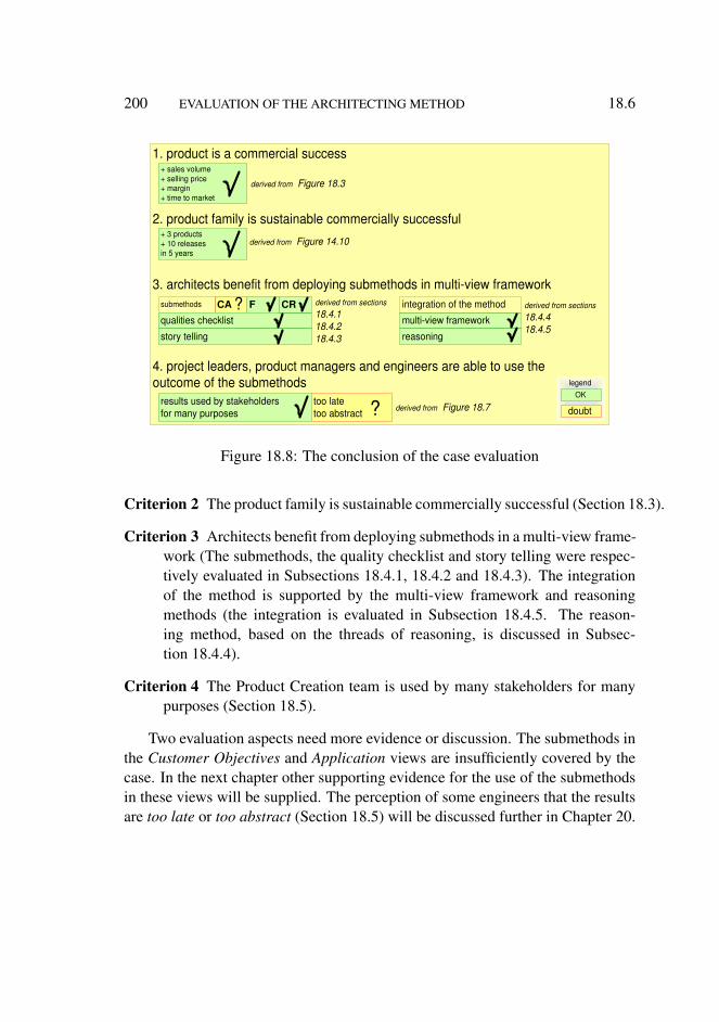
200 EVALUATION OF THE ARCHITECTING METHOD 18.6
1. product is a commercial success
2. product family is sustainable commercially successful
3. architects benefit from deploying submethods in multi-view framework
4. project leaders, product managers and engineers are able to use the outcome of the submethods
+ sales volume + selling price + margin + time to market
multi-view framework
F CA submethods ? integration of the method
results used by stakeholders for many purposes
too late too abstract ?
derived from Figure 18.3
+ 3 products + 10 releases in 5 years
derived from Figure 14.10
qualities checklist
CR
story telling reasoning
derived from sections 18.4.1 18.4.2 18.4.3
derived from sections 18.4.4 18.4.5
derived from Figure 18.7 OK
doubt
legend
Figure 18.8: The conclusion of the case evaluation
Criterion 2 The product family is sustainable commercially successful (Section 18.3).
Criterion 3 Architects benefit from deploying submethods in a multi-view frame-work (The submethods, the quality checklist and story telling were respec-tively evaluated in Subsections 18.4.1, 18.4.2 and 18.4.3). The integrationof the method is supported by the multi-view framework and reasoningmethods (the integration is evaluated in Subsection 18.4.5. The reason-ing method, based on the threads of reasoning, is discussed in Subsec-tion 18.4.4).
Criterion 4 The Product Creation team is used by many stakeholders for manypurposes (Section 18.5).
Two evaluation aspects need more evidence or discussion. The submethods inthe Customer Objectives and Application views are insufficiently covered by thecase. In the next chapter other supporting evidence for the use of the submethodsin these views will be supplied. The perception of some engineers that the resultsare too late or too abstract (Section 18.5) will be discussed further in Chapter 20.
Chapter 19
Evaluation from a Wider Context
19.1 Introduction
The architecting method has been illustrated by means of the medical imagingworkstation case, and this case was used to evaluate the method. Some aspectsof the method could not be evaluated, mostly because these aspects have not beenmade explicit until after the case period.
In Chapter 5 other evaluation possibilities are indicated, such as researchprojects, workshops and courses. The significance of this wider context is thepotential of performing architecting method research with a greater statistical sig-nificance. This chapter does not provide this statistical data. More research, withwell defined research protocols, is needed to obtain more robust results. Observa-tions from this context are discussed, however, to show the potential of researchin this wider context.
Section 19.2 evaluates the method in the research environment, Section 19.3in the workshop settings, and Section 19.4 in the course setting. In these sectionsthe suppotive information is indicated by an identification tag:
c n for CAFCR and multi-view information
q n for quality cheklist information
s n for story telling information
i n for iteration information
u n for usability information
In Section 19.5 the findings are summarized.
201
202 EVALUATION FROM A WIDER CONTEXT 19.2
19.2 Research Environment
For many years research of architecting methods has been performed at PhilipsResearch in the SwA (Software Architectures) group. The research projects inwhich this group participated have been using some of the discussed architecting(sub)methods consciously.
A short description of the research projects that applied some of the methodsis given below:
Family Asset Management How to manage electronic assets, such as movies,pictures, and music? The publication is: [73] is based on this work.
Project infrastructure platform Electronic and software infrastructure (closedcircuit TV, security, public access et cetera) to support project organizationsin the domains of industrial buildings, banks, railway stations, airport ter-minals, and motorways.
Heartcare Image and information integration of all cardio-related informationfrom cathlab to personal monitoring used at home or away.In [2] storytelling is used in the scenario approach. In [57] story telling, called scenar-ios in this article, are used to make architectures better future proof.
Platform for portable multi-media Few or single chip electronics and softwareplatform for the creation of mobile multi-media systems (cellphones, PDAs,personal audio, et cetera).
Software productivity for audiovisual systems How to create the software forintegrated and connected audio and video systems (TVs, set-top boxes, per-sonal video recorders, DVD recorders, et cetera) in a limited amount oftime?
Composable architectures How to create architectures that support composabil-ity? This project consolidated and exchanged experiences over a wide rangeof products: from televisions to cathlabs. The publications [79], [58], [3],and [59] are the first articles and presentations of the BAPO (Business, Ar-chitecture, Process and Organization) and CAFCR models. The PhD the-sis [48] by Jürgen Müller zooms in on the Conceptual and Realization viewsand provides a method to design components that fulfill multiple qualities.In these design views these qualities are called aspects.
In particular the following (sub)methods have been used:
19.3 RESEARCH ENVIRONMENT 203
• the decomposition in the 5 CAFCR views• story telling• qualities• iteration over multiple views
Compared to the medical imaging workstation case these research projectsput more emphasis on the Customer objectives and Application views (c1). Thisresults in more focused research projects and less technology push. Researchersin the platform-oriented projects (infrastructure, multi-media, software productiv-ity), for instance, discovered that solutions were being pushed without any clearneed at the customer side (o1).
Story (or scenario) telling has been explicitly researched and will be subject ofcontinuing research. The following benefits (s1) of story telling were experiencedin the Family Asset management, Heartcare, portable multi-media and softwareproductivity projects:
• Communication with the less technical stakeholders is improved.• Exploration discussions are more to the point: less time is lost on too
generic discussions
Explicit attention for qualities (based on the qualities checklist in Figure 10.3)also helps to focus the research projects and to find the relevant research issuesquicker (q1). Speed of exploration is essential for research projects: identifypromising options, and filtering out unattractive options. The speed of explorationis improved by identifying the essential qualities and by identifying the qualitiesthat can be ignored.
Only a very limited improvement in exploration speed has been observed (i1).The highly individual nature of researchers appears to be a bottleneck. Also thediversity and fragmentation of the group of stakeholders, with their individual in-terests, is a bottleneck. Both bottlenecks hamper the sharing of objectives andthe identification of most important qualities. Improvement in exploration speedis certainly possible, but this requires an interaction of architecting with the con-text of business, processes, and people. New projects at the Embedded SystemsInstitute, which are set up outside the Philips processes and organization, showpromising results. See for instance the Boderc project [23].
No validating or invalidating evidence about the threads of reasoning is ob-tained from the research environment. The threads of reasoning did only exist asa vague notion [55].
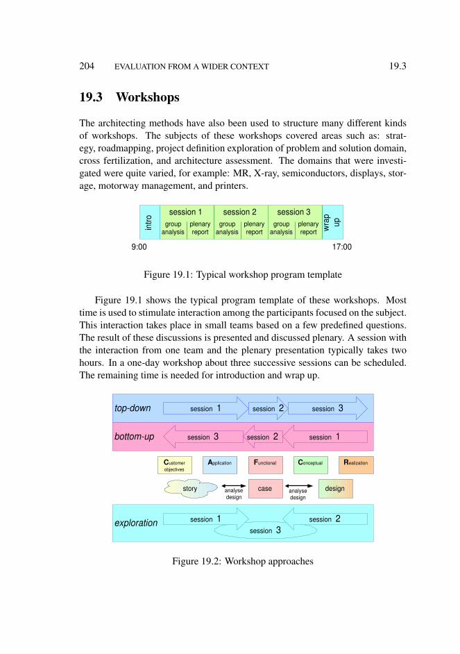
204 EVALUATION FROM A WIDER CONTEXT 19.3
19.3 Workshops
The architecting methods have also been used to structure many different kindsof workshops. The subjects of these workshops covered areas such as: strat-egy, roadmapping, project definition exploration of problem and solution domain,cross fertilization, and architecture assessment. The domains that were investi-gated were quite varied, for example: MR, X-ray, semiconductors, displays, stor-age, motorway management, and printers.
session 1 session 3 session 2
intro
wra
p up
plenary report
group analysis
plenary report
group analysis
plenary report
group analysis
9:00 17:00
Figure 19.1: Typical workshop program template
Figure 19.1 shows the typical program template of these workshops. Mosttime is used to stimulate interaction among the participants focused on the subject.This interaction takes place in small teams based on a few predefined questions.The result of these discussions is presented and discussed plenary. A session withthe interaction from one team and the plenary presentation typically takes twohours. In a one-day workshop about three successive sessions can be scheduled.The remaining time is needed for introduction and wrap up.
top-down
bottom-up
exploration session 3
C ustomer objectives
A pplication F unctional C onceptual R ealization
story case analyse design
design analyse design
session 1 session 2 session 3
session 1 session 2 session 3
session 1 session 2
Figure 19.2: Workshop approaches
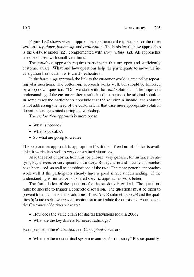
19.3 WORKSHOPS 205
Figure 19.2 shows several approaches to structure the questions for the threesessions: top-down, bottom-up, and exploration. The basis for all these approachesis the CAFCR model (c2), complemented with story telling (s2). All approacheshave been used with small variations.
The top-down approach requires participants that are open and sufficientlycustomer aware. What and how questions help the participants to move the in-vestigation from customer towards realization.
In the bottom-up approach the link to the customer world is created by repeat-ing why questions. The bottom-up approach works well, but should be followedby a top-down question: “Did we start with the valid solution?”. The improvedunderstanding of the customer often results in adjustments to the original solution.In some cases the participants conclude that the solution is invalid: the solutionis not addressing the need of the customer. In that case more appropriate solutiondirections are generated during the workshop.
The exploration approach is more open:
• What is needed?• What is possible?• So what are going to create?
The exploration approach is appropriate if sufficient freedom of choice is avail-able; it works less well in very constrained situations.
Also the level of abstraction must be chosen: very generic, for instance identi-fying key drivers, or very specific via a story. Both generic and specific approacheshave been used, as well as combinations of the two. The more generic approacheswork well if the participants already have a good shared understanding. If theunderstanding is limited or not shared specific approaches work better.
The formulation of the questions for the sessions is critical. The questionsmust be specific to trigger a concrete discussion. The questions must be open toprevent too much bias in the solutions. The CAFCR submethods (c3) and the qual-ities (q2) are useful sources of inspiration to articulate the questions. Examples inthe Customer objectives view are:
• How does the value chain for digital televisions look in 2006?• What are the key drivers for neuro radiology?
Examples from the Realization and Conceptual views are:
• What are the most critical system resources for this story? Please quantify.
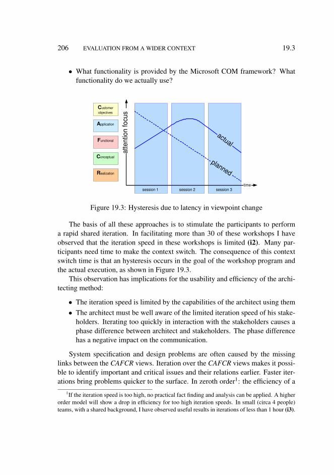
206 EVALUATION FROM A WIDER CONTEXT 19.3
• What functionality is provided by the Microsoft COM framework? Whatfunctionality do we actually use?
session 2 session 3 session 1 time
C ustomer objectives
A pplication
F unctional
C onceptual
R ealization
atte
ntio
n fo
cus
actual
planned
Figure 19.3: Hysteresis due to latency in viewpoint change
The basis of all these approaches is to stimulate the participants to performa rapid shared iteration. In facilitating more than 30 of these workshops I haveobserved that the iteration speed in these workshops is limited (i2). Many par-ticipants need time to make the context switch. The consequence of this contextswitch time is that an hysteresis occurs in the goal of the workshop program andthe actual execution, as shown in Figure 19.3.
This observation has implications for the usability and efficiency of the archi-tecting method:
• The iteration speed is limited by the capabilities of the architect using them• The architect must be well aware of the limited iteration speed of his stake-
holders. Iterating too quickly in interaction with the stakeholders causes aphase difference between architect and stakeholders. The phase differencehas a negative impact on the communication.
System specification and design problems are often caused by the missinglinks between the CAFCR views. Iteration over the CAFCR views makes it possi-ble to identify important and critical issues and their relations earlier. Faster iter-ations bring problems quicker to the surface. In zeroth order1: the efficiency of a
1If the iteration speed is too high, no practical fact finding and analysis can be applied. A higherorder model will show a drop in efficiency for too high iteration speeds. In small (circa 4 people)teams, with a shared background, I have observed useful results in iterations of less than 1 hour (i3).
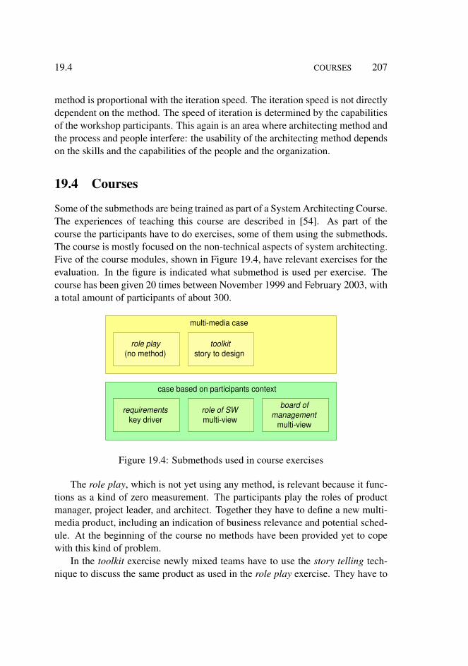
19.4 COURSES 207
method is proportional with the iteration speed. The iteration speed is not directlydependent on the method. The speed of iteration is determined by the capabilitiesof the workshop participants. This again is an area where architecting method andthe process and people interfere: the usability of the architecting method dependson the skills and the capabilities of the people and the organization.
19.4 Courses
Some of the submethods are being trained as part of a System Architecting Course.The experiences of teaching this course are described in [54]. As part of thecourse the participants have to do exercises, some of them using the submethods.The course is mostly focused on the non-technical aspects of system architecting.Five of the course modules, shown in Figure 19.4, have relevant exercises for theevaluation. In the figure is indicated what submethod is used per exercise. Thecourse has been given 20 times between November 1999 and February 2003, witha total amount of participants of about 300.
multi-media case
role play (no method)
toolkit story to design
case based on participants context
requirements key driver
role of SW multi-view
board of management
multi-view
Figure 19.4: Submethods used in course exercises
The role play, which is not yet using any method, is relevant because it func-tions as a kind of zero measurement. The participants play the roles of productmanager, project leader, and architect. Together they have to define a new multi-media product, including an indication of business relevance and potential sched-ule. At the beginning of the course no methods have been provided yet to copewith this kind of problem.
In the toolkit exercise newly mixed teams have to use the story telling tech-nique to discuss the same product as used in the role play exercise. They have to

208 EVALUATION FROM A WIDER CONTEXT 19.4
create a story and to make a start with the analysis and design. Often participantsremark that the method would have helped them greatly in the earlier role playexercise (s3). The teacher can observe the difference between defining a productwithout method (the zero measurement) and defining a product with a story tellingas method. This order of exercises makes the participants aware of the value ofmethods. The learning effect increases by experiencing both situations: withoutand with methods.
The other relevant exercises are all based on the daily context of the partici-pants. The teams are optimized for domain cohesion. Participants are grouped insuch a way that they share more or less the same application area and the sametype of problems. For example, group names are: digital video, MR, X-Ray, auto-motive, and optical storage.
In the requirements exercise they have to make a graph, as described in Sec-tion 8.2, from key driver to requirements (c4). This is often experienced as aneye-opener: how much more exists than the internal design, how little do weknow about the customers!
In the role of software the participants have to make a presentation about thesoftware in their system. The explicit recommendation is to do this with multi-ple diagrams in the Conceptual and Realization view (functional decomposition,layering, flows, size, et cetera) (c5). The presentation should make the intangiblesoftware understandable for non-software people. Without this recommendationmost engineers tend to explain the software from a single diagram (the class di-agram or the layers). Enriching this with other diagrams, such as sizes and otherdimensions, helps significantly to make the software more tangible.
The final exercise is a simulated Board of Management (BoM) presentation [53],where every team has to give a presentation about an important architectural is-sue to a management team that is significantly higher up in the hierarchy. Theyneed to deploy a lot of what they learned during the course. To create a success-ful presentation sufficient customer and business understanding is required (thatis the main interest of this higher management team), but it needs to be related tomultiple relevant architectural views (c6). The choice of views and submethods isentirely up to the participants.
Many architects struggle in day-to-day life with the perceived lack of under-standing of architecting issues by higher management. The BoM exercise ad-dresses this problem by improving the presentation content of the (potential) ar-chitects. For many participants it is an eye opener to present design issues (Con-ceptual or Realization views) in relation with the business justification (CustomerObjectives, Application, and Functional views).

19.5 CONCLUSION 209
In the lecture requirements engineering for the OOTI-curriculum [74] CAFCRand story telling are introduced as means to elicit requirements2. For most of thepostgraduate students customers are far away, they need quite some nudging totake customer needs into consideration. CAFCR (c7) and Story telling (s4) clearlyhelp them to think more in customer terms.
19.5 Conclusion
One of the weak spots of the evaluation by means of the medical imaging worksta-tion was the application of submethods in the Customer objectives and Applicationviews. These submethods have been used much more in all three categories (re-search, workshops, and courses). This resulted in a more clear project focus andmore attention for the customer needs in research projects, compared to previousresearch projects. Application of these views in workshops improved the atten-tion for the customer needs and the project focus relative to the situation beforethe workshop. More focus is for most projects of today a big improvement.
1. product is a commercial success 2. product family is sustainable commercially successful 3. architects benefit from deploying submethods in multi-view framework
4. project leaders, product managers and engineers are able to use the outcome of the submethods
multi-view framework
F submethods integration of the method
project focus more attention for customer needs
qualities checklist
CR
story telling reasoning
c1..c7
o1
CA
c1..c7
iteration speed required ! i1..i3
?
OK
doubt
legend
q1, q2
s1..s4
Figure 19.5: Conclusions of the evaluation in a wider context. The tags are definedin the Sections 19.2 to 19.4.
Figure 19.5 shows the conclusions of this evaluation. These conclusions donot address the product and its future, but only the architect and his stakeholders.The use of the CAFCR multi-view framework helps to cope with complex product
2 Also here the hysteresis effect shown in Figure 19.3 is present: in the five days of this lectureand execution of a case it is often difficult to do the iteration more than once; the design analysis issometimes too superficial, due to the attention on the customer needs.

210 EVALUATION FROM A WIDER CONTEXT 19.5
creation problems. The available submethods are successfully used in researchenvironments, workshops, and courses. The qualities from the quality checklisthelped to bring focus to research projects. No supporting evidence with respect tothreads of reasoning is obtained from these sources.
A large majority of people lack the skills to iterate very fast over the CAFCRviews. They have, however, no problems in following the reasoning when ex-plained. The conclusion is that those who act as architect and deploy this architect-ing method must have the capability to iterate quickly. In case of an architectingteam at least one of the members of the team must have this iterating capability.
Chapter 20
Balancing Genericity andSpecificity
20.1 Introduction
The subtitle of this thesis is ”Balancing Genericity and Specificity”. The back-ground of this subtitle is that nearly all development teams of complex systemsseem to struggle with this balance.
Section 20.2 discusses this issue in a generic way. Section 20.3 illustrates thethe role of this balance in case of the medical imaging workstation. Section 20.4discusses the interaction of generic and specific elements in the context of thearchitecting method.
20.2 Core Qualities
The deliverables of the architect are mostly at a high conceptual level. The systemspecification defines the outline of the system and the system design provides theoutline of implementation of the system. Most of the output is rather generic:defining many properties of a system with a minimum set of words and diagrams.The engineers work at all the specific details of the system, which can be millionslines of code or millions of transistors on a chip.
Figure 20.1 shows the two approaches, generic and specific, as complemen-tary approaches in a core quadrant representation, as described by Daniel Off-man [60]. The top left quadrant describes the core qualities of a generic systemsapproach. The top right quadrant describes the pitfalls that occur when the core
211
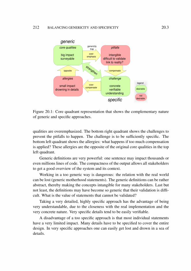
212 BALANCING GENERICITY AND SPECIFICITY 20.3
core qualities
big impact surveyable
pitfalls
intangible difficult to validate
link to reality?
generic
challenge
concrete verifiable
understanding
allergies
small impact drowning in details
specific
desirable
not desirable
compensate opposite
strengthen
over- emphasis
genericity trap
over- compensate
legend
Figure 20.1: Core quadrant representation that shows the complementary natureof generic and specific approaches.
qualities are overemphasized. The bottom right quadrant shows the challenges toprevent the pitfalls to happen. The challenge is to be sufficiently specific. Thebottom left quadrant shows the allergies: what happens if too much compensationis applied? These allergies are the opposite of the original core qualities in the topleft quadrant.
Generic definitions are very powerful: one sentence may impact thousands oreven millions lines of code. The compactness of the output allows all stakeholdersto get a good overview of the system and its context.
Working in a too generic way is dangerous: the relation with the real worldcan be lost (generic motherhood statements). The generic definitions can be ratherabstract, thereby making the concepts intangible for many stakeholders. Last butnot least, the definitions may have become so generic that their validation is diffi-cult. What is the value of statements that cannot be validated?
Taking a very detailed, highly specific approach has the advantage of beingvery understandable, due to the closeness with the real implementation and thevery concrete nature. Very specific details tend to be easily verifiable.
A disadvantage of a too specific approach is that most individual statementshave a very limited impact. Many details have to be specified to cover the entiredesign. In very specific approaches one can easily get lost and drown in a sea ofdetails.
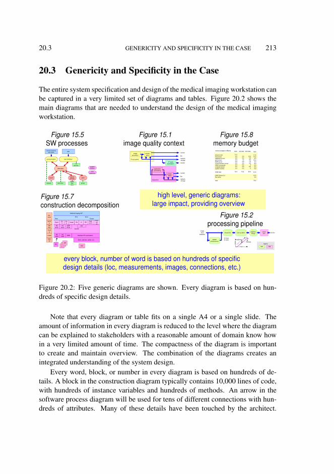
20.3 GENERICITY AND SPECIFICITY IN THE CASE 213
20.3 Genericity and Specificity in the Case
The entire system specification and design of the medical imaging workstation canbe captured in a very limited set of diagrams and tables. Figure 20.2 shows themain diagrams that are needed to understand the design of the medical imagingworkstation.
shared code UI process database server print server DOR server communication server UNIX commands compute server system monitor
ASW total
UNIX Solaris 2.x file cache
total
obj data
3.0 3.2 1.2 2.0 2.0 0.2 0.5 0.5
12.6
bulk data
12.0 3.0 9.0 1.0 4.0
0 6.0
0
35.0
code
11.0 0.3 0.3 0.3 0.3 0.3 0.3 0.3 0.3
13.4
total
11.0 15.3
6.5 10.5
3.3 6.3 0.5 6.8 0.8
61.0
10.0 3.0
74.0
memory budget in Mbytes
Figure 15.8 memory budget
Figure 15.1 image quality context
Figure 15.7 construction decomposition
user interface communication
data base
export print optical storage
optical disk drive
printer disk drive network
UI devices
system monitor
Unix daemons
remote systems and users user
X-ray system
image generation
presen- tation
monitor
film
network, storage
Easyvision
application processing
presen- tation
monitor
film
network, storage
3 rd party workstation monitor
Figure 15.5 SW processes
spatial enhancement
interpolate Look up table graphics merge
colour LUT
legend
HW SW
monitor image from
database ou
tput
input
contrast
brightness bi-linear bi-cubic
Figure 15.2 processing pipeline
DSI
3M RC
Desk, cabinets, cables, etc.
Standard IPX workstation DOR HC interf
RC interf
SunOS
NIX RC driver
HC driver
DOR driver
Spool HC U
Sto re Image Gfx UI DB PMS-
net in
PMS- net out
Medical Imaging R/F
Start up
Install
Confi g
SW keys
servic e
dev. tools Print Store
View Cluster
every block, number of word is based on hundreds of specific design details (loc, measurements, images, connections, etc.)
high level, generic diagrams: large impact, providing overview
Figure 20.2: Five generic diagrams are shown. Every diagram is based on hun-dreds of specific design details.
Note that every diagram or table fits on a single A4 or a single slide. Theamount of information in every diagram is reduced to the level where the diagramcan be explained to stakeholders with a reasonable amount of domain know howin a very limited amount of time. The compactness of the diagram is importantto create and maintain overview. The combination of the diagrams creates anintegrated understanding of the system design.
Every word, block, or number in every diagram is based on hundreds of de-tails. A block in the construction diagram typically contains 10,000 lines of code,with hundreds of instance variables and hundreds of methods. An arrow in thesoftware process diagram will be used for tens of different connections with hun-dreds of attributes. Many of these details have been touched by the architect.

214 BALANCING GENERICITY AND SPECIFICITY 20.4
However, many more details will never be touched by the architect, as describedin Sections 7.2 and 7.5. Submethods such as the Question Generator, see Sec-tion 9.2.3, help in finding the details to be covered.
The sampling of reality by touching many of the implementation details is thebalancing factor in generating the required high-level, compact output. Systemdesigns that do not use such fact finding procedures to connect to reality via suchfact finding are very risky and do not deserve to be called system design.
20.4 Genericity and Specificity in the Architecting Method
The architecting method has many submethods, which invite to be generic. TheCAFCR model and the quality checklist are very generic. Every submethod ispowerful, and can have a significant impact on the specification and the design.Figure 20.3 positions the architecting method with respect to the level of generic-ity or specificity, using the scale of abstraction levels from Figure 7.3. The storytelling complements the CAFCR submethods and qualities by addressing specificdetails. The threads of reasoning integrate and balance the generic and specificsubmethods.
generic: provide overview
specific: link to reality via facts
story use case analyse
design
partial design analyse
design
C ustomer objectives
A pplication F unctional C onceptual R ealization
10 6
10 3
1
leve
l of d
etai
l, se
e fig
ure
7.3
thread of reasoning: integration by fast iteration
Figure 20.3: The CAFCR views provide generic insight; story telling enablesanalysis of specific facts.
20.5 CONCLUSION 215
Story telling is an effective means to make discussions concrete. A good storyis overspecific. On purpose a very narrow, but representative, sample of the targetuse is described and analyzed. This forces the architect and the designers to lookinto many specific details.
The threads of reasoning iterate between the generic models and objectivesand these details that enable or obstruct the design. The threads of reasoning helpto balance genericity and specificity.
Section 7.2 explains the dynamic range of description and implementationfacts that needs to be covered by the submethods. The evaluation in Chapter 18concludes that the method satisfies the needs. The only exception is that theoutcome is sometimes too abstract and that the outcome is sometimes too late.The criticism of being too abstract is directly related to the generic nature of theCAFCR submethods. The step from the generic diagrams in Figure 20.2, withhundreds of facts, to the detailed designs of modules and components, with tensof thousands of detailed facts, spans a factor of more than one hundred! Mak-ing the generic diagrams more detailed worsens the surveyability and worsens thetimely availability, which is the second concern. This tension between the needfor genericity for power and understanding, and the need for specificity for thelink with reality, is the core problem that architecting methods must tackle.
20.5 Conclusion
The overall architecting methods described in this thesis work successfully inproducts that span a very large dynamic range of concerns. The criticism of someof the stakeholders clearly identifies a major attention point for the architect whenhe is deploying the method: the balance between genericity and specificity.
The heuristics for the architect in finding the balance are:
• Genericity: overview diagrams fit on a single A4 (20.3).• Specificity: the coverage of detailed facts may vary widely over different
parts of the system (20.3).• Story telling facilitates specific discussion, analysis, and design (20.4).• Threads of reasoning integrate generic and specific viewpoints (20.4).

216 BALANCING GENERICITY AND SPECIFICITY 20.5
Chapter 21
Reflection on Research Methodto Study Architecting Methods
21.1 Introduction
In this chapter we look back at the research method. Where did the researchmethod support the search for successful architecting methods? What aspects ofthe research methods can be improved?
Section 21.2 discusses the value of the research question. The hypothesis, thecriteria, and the evaluation are discussed in Section 21.3. Section 21.4 looks backat the case description. The conclusion is formulated in Section 21.5.
21.2 Research Question
The explicit formulation of a research question has helped to focus the subject ofresearch. The research objectives and the context have been made explicit. Theintention of the research question was to limit the scope to a ’manageable’ sizedresearch project.
The human factor is quite dominantly present in the success probability ofthe architecting method. Figure 21.1 shows the original research question, witha characterization into soft and hard factors. It is immediately clear that manysoft factors dominate in the research question. These soft factors can broadenthe research scope tremendously. A lot of effort in writing the thesis went intomaintaining focus and into balancing hard and soft factors.
217

218 REFLECTION ON RESEARCH METHOD TO STUDY ARCHITECTINGMETHODS 21.4
What architecting methods enable
the creation of
successful
products
in a dynamic market
developed in a heterogeneous industrial context
satisfied customers thriving business
some poor, some excellent, mostly average
in time within economic constraints
uncertainty rules need for innovation agility required
normal distribution of engineering skills
views, stakeholders, applications, concerns, needs, expectations, interests functions, features, qualities, requirements, systems, technologies, standards, disciplines suppliers, sites, cultures, employees, educations, tools, legacy, other vendors, legislation
technology and software intensive
hard
soft
Figure 21.1: The original research question, characterized with hard and soft fac-tors
21.3 Hypothesis, Criteria, and Evaluation
The hypothesis (Section 6.3) extended the research question ((Section 6.2) into astatement that can be validated. The main extension is the addition of how. Thecriteria (Section 6.4) sharpen the hypothesis by adding who. The criteria werevery valuable in the evaluation, because they focused the evaluation discussion toa limited set of issues. The separation of the criteria for the different stakeholderswas essential, because success is measured differently for different stakeholders.
The limitation of this research method is that the hypothesis is only madeplausible. The architecting method has been demonstrated successfully in thecase and partially in other situations. The hypothesis is not invalidated. In thistype of research, with many soft factors, invalidation experiments are difficult: isthe hypothesis invalid or did the context not fit in the soft preconditions? Repeatedinvalidation efforts are needed to increase the plausibility of the method.
21.4 Case Description
The case description is indispensable for this type of research. It illustrates thearchitecting method much more effectively than any theoretical text can do. Thecase is also essential to evaluate the hypothesis. The main weakness is that onlyone case is described. The soft factors are seen as context in this thesis. Softfactors play a dominant role in practice and as shown in Section 21.2. More

21.5 CONCLUSION 219
case descriptions are needed to separate the method contribution better from theimpact of the soft factors. Unfortunately, most cases contain too much sensitiveinformation for the market or the competition. The research can also be extendedby including more soft factors in the case description. Describing more soft factorscan be privacy sensitive, because it describes behavior of individuals.
Courses and research projects are less competition sensitive. Describing casesfrom courses and research projects will help to improve the foundation of researchmethods. Of course, real industrial cases are more supportive than the more indi-rect cases from research and education.
21.5 Conclusion
The overall research method (research question, hypothesis, criteria, case andevaluation) worked satisfactory, because it helped to articulate the objectives andto focus the research. More case descriptions and more cases describing soft fac-tors will increase the value of this type of research. In Chapter 22 future researchdirections are discussed.

220 REFLECTION ON RESEARCH METHOD TO STUDY ARCHITECTINGMETHODS 21.5
Chapter 22
The Future of ArchitectingResearch
22.1 Introduction
The development of the system architecting discipline takes place in a dynamiccontext as shown in Figure 22.1. The natural habitat for system architects isformed by the classical academic disciplines, the standardization bodies, and thecommunities and conferences. The classical academic disciplines are more ma-ture, but will continue to develop. Many standardization bodies and professionalsocieties are working on system engineering and architecting. Many communitiesexist where best practices and research results are exchanged in forums, confer-ences, and many more interactive ways. Sources of inspiration for the develop-ment of the system architecting discipline are the management disciplines and thehuman sciences. Management disciplines are growing, and share the integratingfunction with the architecting discipline. The human sciences are perceived assoft, but as shown in Chapter 21, the architecting discipline will have to cope withmany soft factors.
The development of the systems architecting discipline involves the creation aframe of reference that helps to relate systems architecting with this context. Theassociated body of knowledge is discussed in Section 22.2.
Research and consolidation of knowledge is not the only issue to be addressed.The knowledge does get its value if it there are people with the skills to use thisknowledge. The translation of the results into an education for system architects iscomplementary to the knowledge consolidation. Section 22.3 discusses the need
221

222 THE FUTURE OF ARCHITECTING RESEARCH 22.2
natural system architect habitat
system architecting
classical disciplines
mathematics, physics, chemistry, biology, medicine, economics,
computer science, mechanical engineering, electronical engineering
management disciplines
technology management, business management, process management,
quality assurance, project management
standardisation bodies, professional societies
IEEE, ISO, ACM, IFIP, INCOSE
communities, conferences
requirements engineering, reliability engineering,
product lines, SW architecting,
TRIZ, RUP
human sciences
psychology sociology pedagogy
anthropology theology
Figure 22.1: The context of architecting
for a systems architecting curriculum.Section 22.4 summarizes what needs to be done to develop the discipline of
system architecting.
22.2 Build up of Body of Knowledge
The body of knowledge to be built consists of different kinds of information. Theframe of reference contains reference information, which should help people toposition pieces of know-how. For instance:
• classification schemes such as taxonomies or ontologies• definitions of concepts and terms such as glossaries• definitions of scope in terms of objectives• relationships by means of frameworks• capturing best practices and generic know how in principles and heuristics• a library of submethods
22.3 CURRICULUM 223
• a library of case descriptions• connections with the context• systematic research of soft factors, for instance by means of questionnaires• supporting tools
In such a framework we need content, such as a library of case descriptions,and a library of submethods. The methods capture how to approach a system leveldesign problem. A large set of methods is needed, due to the wide variety of prob-lems at system level. Case studies are the carriers of research and consolidationof systems architecting know-how. Very few product developments of industrialsize are documented in publicly accessible ways. One of the main hurdles is theconfidentiality of the information. It is nevertheless crucial to get a richer set ofcase descriptions to develop the discipline further. Note that good cases documentthe product architecture itself, the architecting methods used, and evaluate the useof these methods.
One of the big challenges is to keep up with the growth of functionality, per-formance, and complexity, as described in Section 5.3. This requires a growthof architecting methods in depth and breadth. More breadth is needed in the ca-pability of handling an even larger dynamic range of abstraction levels. At thesame time we have to link the new discipline to the existing sciences, a growth indepth. This link requires a solid research method that facilitates the substantiationof evidence. In general the body of knowledge must be connected to the contextshown in Section 22.1: classical disciplines, communities, standardization bodies,management disciplines and the human sciences.
Chapter 19 showed the potential of using courses and workshops to evaluatearchitecting methods with somewhat more statistical relevance. However, in orderto use this source of information we need research methods that work in thatenvironment. The human sciences are much more used to this type of researchand can provide inspiration for this type of research methods.
22.3 Curriculum
The typical growth of an architect is used as reference to define desired educa-tion steps for architects. The top of Figure 22.2 shows the typical growth of anarchitect. The growth early in the career is mostly in technical skills. Later thenon-technical skills get more attention, in areas such as application, business andprocess.

224 THE FUTURE OF ARCHITECTING RESEARCH 22.3
ESA SW
Execution architecture
SARCH
ESA stakeholders
available
missing
external
architecture school
root technical know-how
generalist technical
know-how
business, application insight
process insight
psycho-social skills
apply theory in practice
become all-round
experience the non-technical aspects
see every human as an individual
System design methods
Bredemeyer SW architecture
Architectural reasoning
ESA s ystem ESA
silicon
ESA mechatronics
marketing, process and many more
Bredemeyer - Role of the architect
Thomas Gilb - EVO, requirements eng
mathematics physics chemistry mechanical engineering computer science electronical engineering
conventional curriculums
advanced SARCH
reliability engineering QFD and more
legend
Figure 22.2: Curriculum system architecting
Conventional education is focused on one discipline. This type of educationis a good fundament for a potential architect. An architect must have experiencein at least one of the technology disciplines, to:
• know and understand detailed technical and engineering problems• be taken serious as peer for mono-disciplinary engineers
The next step is to broaden the potential architect by providing technical edu-cation in other disciplines. At this moment a few courses in this area are availablein the ESA (Embedded Systems Architecting) course [24]. This course consists of4 modules: Software, Silicon, System, and Stakeholders. Software, Silicon, andSystems broaden the technical scope to electronics plus software, illustrated by anumber of system technologies such as audio and video. The “harder” disciplines,such as mechatronics, are not yet available in this format.
The real gap in education is in the area of multi disciplinary system designmethods. Some communities have created courses in well-defined areas such asreliability engineering (for example FMEA), or in less tangible areas such as Qual-ity Function Deployment (QFD). Many existing design problems, however, arenot yet covered by design methods, let alone by education.
The integration of the system level design methods, addressing one or twoobjectives, into systematic reasoning at system level is the next challenge. Againa lot of method development is needed before education makes sense.

22.4 CONCLUSION 225
The next maturity step of the architect is supported by borrowing methods andeducational material from other disciplines (marketing, process and organization,et cetera).
The most important contribution to the growth of an architect is the practicalexperience. Working at real problems is crucial. At Philips Research an archi-tecture school is set up, where potential architects work on projects, guided bymore experienced engineers. Concurrently they participate in a set of courses, forexample the ESA course mentioned above.
22.4 Conclusion
For the development of system architecting as a discipline, we have to :
• develop a framework to position architecting in the context• create a library of submethods• develop supporting tools• build up a library of case descriptions• research new architecting methods to cope with more breadth and a larger
dynamic range• develop research methods to cope with the soft factors• create a curriculum to educate potential architects

226 THE FUTURE OF ARCHITECTING RESEARCH 22.4
Chapter 23
Conclusion
We have discussed the industrial context of embedded systems architecting, andthe distance between the industrial context and academic research. The challengeto bridge the gap between the industrial and academic worlds is addressed byusing a research method based on a hypothesis and a case. The hypothesis istested by applying the CAFCR method on a Medical Imaging Workstation case.The CAFCR method maps well on this case, although the CA views have beenunderexposed in the historical context of the case. The use of many differentviews, submethods, qualities and use cases, as proposed in this thesis, contributedsignificantly to the success of the Workstation. The beneficial characteristics ofthe CAFCR method are:
• integral and multi-disciplinary• goal-oriented• practical, based on industrial experience• flexible• builds on standards• support for short innovation cycles
This area of research has many connections to both the engineering sciencesand the human sciences. One of the main challenges for embedded systems ar-chitecting research is to balance the genericity and specificity. Very generic state-ments are difficult to substantiate and use, but very specific statements might beinfeasible due to the sheer amount of required know-how.
Future research work has to be done to substantiate the evaluation from thewider context. In general the area of embedded systems research is young and
227

228 CONCLUSION 23.0
lots of research work is required to develop this area, ranging from ontologiesand heuristics to extending the library of submethods. Special attention is neededfor the many soft factors involved. Based on this research a curriculum has to bedeveloped for the education of system architects.

Part V
Appendices and Bibliography
Acknowledgements
Abbreviations
Bibliography
Summary
Samenvatting
229

Acknowledgements
Wim Vree coached me in the scientific mores and provided a lot of inspiration.Wim helped in determining the focus in the broad subject of systems architecting,and in structuring the complex material. Wim’s enthusiasm contributed a lot tothis thesis. Martin Rem has provided lots of feedback on the reasoning and logicof this thesis. As side effect Martin also corrected many language errors, and heprovided many hints to improve the readability significantly. Martin’s relentlessprogress and positive attitude were very stimulating.
The other members of the dissertation committee, Peter Kroes, Henk Sips,René Wagenaar, Dieter Hammer, and Pieter Hartel provided helpful feedback afterreading the manuscript.
Many managers have encouraged me and facilitated me to write this thesis:Frans Beenker, Rick Harwig, Jaap van der Heijden, Marloes van Lierop, MartinRem, and Eric van Utteren.
The composable architecture project at Philips Research invented the acronymCAFCR and created the foundation of the CAFCR method. Members of thisproject were: Pierre America, Marcel Bijsterveld, Peter van den Hamer, HansJonkers, Jürgen Müller, Henk Obbink, Rob van Ommering, William van der Ster-ren, and Jan Gerben Wijnstra.
Many colleagues contributed to this thesis by providing data or feedback. Withthe danger of forgetting someone I acknowledge the contribution of the followingpeople: Peter Bingley, Robert Deckers, Martien Dijks, Christian Huiban, EugeneIvanov, Peter Jaspers, Auke Jilderda, Ton Kostelijk, Nico Schellingerhout, Berryvan der Wijst, and Rik Willems.
My wife Lia Muller-Charité encouraged me during all the phases precedingthe writing of the thesis, as well as during the actual writing. She also helped meby reflecting and discussing the contents itself.
231

232 ACKNOWLEDGEMENTS
Abbreviations
1471 IEEE standard defining an architecture descriptions
9001 ISO standard defining quality management
9126 ISO standard describing a quality framework
ACR The American College of Radiology
ASML Lithography Company in Veldhoven, the Netherlands
ATAM Architecture Tradeoff Analysis Method by Rick Kazman
BAPO Business Architecture Process Organization
BoM Board of Management
BoM Bill of Material
CAFCR Customer Objectives, Application, Functional, Conceptual, Realization
C/B Contrast/Brightness
CFO Chief Financial Officer
CIS Cardiology Information System
CMO Chief Marketing Officer
COM Component Object Model, by Microsoft
CoO Cost of Ownership
CPU Central Processing Unit
233
234 ABBREVIATIONS
CT Computer Tomography
CTO Chief Technical Officer
DB DataBase
DICOM Digital Imaging and Communications in Medicine
dll dynamic link library
DOR optical disk
DSP Digital Signal Processor
DVD optical disk succeeding the CD, officially no abbreviation, but some peopleuse it for Digital Video Disc or Digital Versatile Disc
EMC Electro-Magnetic Compatibility
ESA Embedded Systems Architecting course
ESI Embedded Systems Institute
EVO Evolutionary Project Management method by Thomas Gilb
FDA Food and Drug Administration
FFT Fast Fourier Transform
FMEA Failure Mode Effect Analysis
FRS Functional Requirements Specification
fte Full Time Equivalent, unit of planning indicating a full time available person
GE General Electric
gfx graphics
GHz Giga Hertz
GSM Cell phone standard
GST General Systems Theory
HACCP Hazard Analysis And Critical Control Point
ABBREVIATIONS 235
HCU Hardcopy Unit
HD High Definition video
HIPAA Health Insurance Portability and Accountability Act
HIS Hospital Information System
HL7 Health Level 7 standard defining meta information for health care
HQ High Quality audio
HW Hardware
IEEE Institute of Electrical and Electronics Engineers, Inc
INCOSE International Council on Systems Engineering
I/O Input/Output
IQ Image Quality
ISO International Organization for Standardization
IT Information Technology
KOALA a SW component technology used in Philips consumer products
kB kilo Bytes
kloc kilo lines of code
LIS Laboratory Information System
LUT Look Up Table
MB, MByte Mega-Byte
MB, Mbit Mega-bit
MHz Mega Hertz
MLC Material and Labor Cost
MPEG Moving Pictures Experts Group, a compression standard for movies
236 ABBREVIATIONS
MPR Multi Planar Reformatting
mrad milliradial
MRI Magnetic Resonance Imaging
MRP Material Resource Planning
NEMA National Electrical Manufacturers Association
nm nanometer, 10−9 meter
OIT Object Instantiation Tracing
OO Object-Oriented
OS Operating System
OSI Open System Interconnect
PACS Picture Archiving and Communication System
PCP Product Creation Process
PCR Radiography based on Phosphor plate reader
PDA Personal Digital Assistant
PIP Picture In Picture
PMS Philips Medical Systems
PMSnet Philips interoperability protocol, extending the ACR/NEMA or DICOMprotocol
ps Unix command to show process statistics
PVR Personal Video Recorder
QFD Quality Function Deployment
RAM Random Access Memory
RC Remote Control
RF Radio Frequency
ABBREVIATIONS 237
RIS Radiology Information System
ROI Return On Investment
RUP Rational Unified Process
SAAM A Method for Analyzing the Properties of Software Architectures by RickKazman
SARCH Course System Architecting at Center of Technical Training (CTT) ofPhilips
SD Standard Definition video
SDS System Design Specification]
SE Systems Engineering
SEI Software Engineering Institute
SNR Signal to Noise Ratio
SPC Statistical Process Control
SPS System Performance Specification
SRS System Requirements Specification
SW Software
SwA Software Architectures group at Philips Research
TPD Technical Product Documentation
TPS Test Performance Specification
TRIZ Theory of Inventive Problem Solving
TXT Teletext
UI User Interface
UNIX widely used Operating System
URF Universal Radiography Fluoroscopy

238 ABBREVIATIONS
US Ultra Sound
VAP Visual Architecting Process by Bredemeyer
VDE Verband der Elektrotechnik Elektronik Informationstechnik
VDU Video Display Unit
vmstat Unix command to show (virtual) memory statistics
WWHWWW Why What How Where When Whom
WYSIWYG What You See Is What You Get
X Window management system
xDAS Data Acquisition System, the x is the version or the type
xFEC Front End Controller, the x is the version or the type
ZIFA Zachman Institute for Framework Advancement
Bibliography
[1] Genrich Altshuller. The Innovation Algorithm; TRIZ, systematic innovationand technical creativity. Technical Innovation Center, Worcester, MA, 2000.Translated, edited and annotated by Lev Shulyak and Steven Rodman.
[2] Pierre America. Making architectures future-proof using scenarios.http://www.serc.nl/lac/2003/presentaties/Track1/P.America.pdf, 2003.
[3] Pierre America, Henk Obbink, Rob van Ommering, and Frank van der Lin-den. COPAM: A component-oriented platform architecting method familyfor product family engineering. In Patrick Donohoe, editor, Proceedings ofthe First Software Product Line Conference, August 2000.
[4] Audrey Apfel. BVIT: Frameworks and methodologies that work.http://www3.gartner.com/resources/113500/113516/113516.pdf, 2003.
[5] Apple Computer, Inc. The Objective-C Programming Language.http://developer.apple.com/documentation/Cocoa/Conceptual/ObjectiveC/index.html, 2003.
[6] Architecture Working Group (AWG). IEEE Recommended Practice for Ar-chitectural Description of Software-Intensive Systems. The Institute of Elec-trical and Electronics Engineers, Inc., 2000.
[7] Arthur D Little Global Management Consultants. Technology managementstudy, 1998. confidential report at ASML. Complete derivation from 5 cus-tomer key driver to about 250 critical waferstepper technologies.
[8] J. E. Beasley. OR-notes. http://mscmga.ms.ic.ac.uk/jeb/or/basicor.html.
239

240 BIBLIOGRAPHY
[9] Per Bjurï¿12us and Axel Jantsch. MASCOT: A specification and cosimula-
tion method integrating data and control flow. http://jamaica.ee.pitt.edu/Archives/ProceedingArchives/Date/Date2000/papers/2000/date00/pdffiles/03a_2.pdf,2000.
[10] Dana Bredemeyer. Definitions of software architecture. http://www.bredemeyer.com/definiti.htm, 2002. large collection of defini-tions of software architecture.
[11] Dana Bredemeyer and Ruth Malan. Resources for software architects.http://www.bredemeyer.com/, 1999.
[12] Dana Bredemeyer and Ruth Malan. Role of the software architect. http://www.bredemeyer.com/pdf_files/role.pdf, 1999.
[13] Dana Bredemeyer and Ruth Malan. The visual architecting process.http://www.bredemeyer.com/pdf_files/WhitePapers/VisualArchitectingProcess.PDF, 2003.
[14] Florian Cajori. A history of Mathematical Notations. The Open Court Pub-lishing Company, 1928.
[15] Samidh Chakrabarti and Aaron Strauss. Carnival booth: An al-gorithm for defeating the computer-assisted passenger screening sys-tem. http://swissnet.ai.mit.edu/6805/student-papers/spring02-papers/caps.htm, 2002. Shows that security systemsbased on secret designs are more vulnerable and less secure.
[16] Alistair Cockburn. Writing Effective Use Cases. Addison-Wesley, 2000.
[17] Hay Management Consultants. Technology management cycle. Hay Man-agament Consultants showed me this model in 1997/1998, taken from anarticle by a Japanese author. The original title of the Japanese article is un-known.
[18] Gerardo Daalderop, Ann Ouvry, Luc Koch, Peter Jaspers, Jürgen Müller,and Gerrit Muller. PACS assessment final report, version 1.0. confidentialinternal report XLB050-96037, September 1996.
[19] Paul de Witte. CTT course SARCH. http://www.extra.research.philips.com/ctt/ctt_it/sarch.htm, 1999.

BIBLIOGRAPHY 241
[20] Jean-Marc DeBaud and Klaus Schmid. A systematic approach to derivethe scope of software product lines. In 21st international Conference onSoftware Engineering: Preparing for the Software Century, pages 34–47.ICSE, 1999.
[21] J. C. DeFoe (Editor). An identification of pragmatic principles. http://www.incose.org/workgrps/practice/pragprin.html, 1999.
[22] Remco M. Dijkman, Luï¿12s Ferreira Pires, and Stef M.M. Joosten.
Calculating with concepts: a technique for the development of businessprocess support. In A. Evans, R. France, A. Moreira, and B. Rumpe,editors, Lecture Notes in Informatics, volume 7, pages 87–98. GI-edition,2001. http://www.google.com/url?sa=U&start=3&q=http://www.ub.utwente.nl/webdocs/ctit/1/00000068.pdf&e=7764 Proceedings of the UML 2001 Workshop on Practical UML-BasedRigorous Development Methods.
[23] Embedded Systems Institute. Boderc project. https://www.embeddedsystems.nl/Boderc, 2003.
[24] Embedded Systems Institute. Course on embedded systems archi-tecting. https://www.embeddedsystems.nl/PRO1/general/show_document_general.asp?documentid=676, 2003.
[25] EventHelix.com. Publish-subscribe design patterns. http://www.eventhelix.com/RealtimeMantra/Patterns/publish_subscribe_patterns.htm, 2000.
[26] Thomas Gilb. Competitive Engineering: A Handbook For Systems Engi-neering, Requirements Engineering, and Software Engineering Using Plan-guage. Elsevier Butterworth-Heinemann, London, 2005.
[27] H Gomaa. Software Design Methods for Real-time Systems. Addison-Wesley, 1993.
[28] Robert J. Graham and Randall L. Englund. Creating an Environment forSuccessful Projects; The Quest to Manage Project Management. Jossey-Bass Publishers, San Fransisco, CA, 1997.
[29] Volker Haarslev. A fully formalized theory for describing visual notations. InProceedings, International Workshop on Theory of Visual Languages, Gub-bio, Italy, 1996.
242 BIBLIOGRAPHY
[30] John L. Hennessy, David A. Patterson, and David Goldberg. Computer Ar-chitecture: A Quantitative Approach. Morgan Kaufmann, 1996.
[31] F. Heylighen and C. Joslyn. What is systems theory? http://pespmc1.vub.ac.be/SYSTHEOR.html, 1992. Principia Cybernetica Web (Prin-cipia Cybernetica, Brussels).
[32] Derek K. Hitchins. Putting systems to work. http://www.hitchins.co.uk/, 1992. Originally published by John Wiley and Sons, Chichester,UK, in 1992.
[33] Christine Hofmeinster, Robert Nord, and Dilip Soni. Applied Software Ar-chitecture. Addison-Wesley, 2000.
[34] Laurence Holt. Goal-oriented design. unknown, 2004 (planned). A previewwas presented at the Gilb Systecture event 2003, London, June 2003.
[35] Robert Hunt. The origins of proof iv: The philosophy of proof. http://plus.maths.org/issue10/features/proof4/, 2000.
[36] INCOSE. International council on systems engineering. http://www.incose.org/toc.html, 1999. INCOSE publishes many interesting ar-ticles about systems engineering.
[37] Carnegie Mellon Software Engineering Institute. How do you define soft-ware architecture? http://www.sei.cmu.edu/architecture/definitions.html, 2002. large collection of definitions of softwarearchitecture.
[38] ISO/IEC. ISO 9126: The standard of reference. http://www.cse.dcu.ie/essiscope/sm2/9126ref.html, 1991.
[39] Hans Jonkers. Interface-centric architecture descriptions. In WICSA 2001,Amsterdam, 2001.
[40] R. Kazman, M. Klein, and P. Clements. ATAM: Method for architectureevaluation. citeseer.nj.nec.com/kazman00atam.html, 2000.
[41] Rick Kazman, Leonard J. Bass, Mike Webb, and Gregory D. Abowd.SAAM: A method for analyzing the properties of software architectures.In International Conference on Software Engineering, pages 81–90. ICSE,1994.

BIBLIOGRAPHY 243
[42] Kurt Keutzer and Richard Newton. Productivity gap. http://lark.vmei.acad.bg/asic/lectures/intro/slide1-5.htm, 2000.
[43] Philippe B. Kruchten. The 4+1 view model of architecture. IEEE Software,pages 42–50, November 1995.
[44] Ben Lieberman. The art of modeling; part i: Constructing an analyti-cal framework. http://www.therationaledge.com/content/aug_03/f_modeling_bl.jsp, 2003.
[45] Charles C. Mann. Homeland insecurity. The Atlantic Monthly, pages 81–102, September 2002. Volume 290, No. 2T; Very nice interview with BruceSchneier about security and the human factor.
[46] James N. Martin. Systems Engineering Guidebook. CRC Press, Boca Raton,Florida, 1996.
[47] Carver Mead and Lynn Conway, editors. Introduction to VLSI systems.Addison-Wesley, 1980. Chapter 7: System Timing, by Charles L. Seitz.
[48] Jï¿12 rgen K. Mï¿1
2 ller. The Building Block Method: Component-Based Archi-tectural Design for Large Software-Intensive Product Families. Universiteitvan Amsterdam, 2003. Ph.D. thesis.
[49] James Mohr. The linux tutorial; run-levels. http://www.linux-tutorial.info/cgi-bin/display.pl?65&99980&0&3, 1997.
[50] Gerrit Muller. Technology improvement plan. confidential internal report,June 1994.
[51] Gerrit Muller. CTT course SARCH. http://www.gaudisite.nl/SARCHcoursePaper.pdf, 1999.
[52] Gerrit Muller. Case study: Medical imaging; from toolbox to product toplatform. http://www.gaudisite.nl/MedicalImagingPaper.pdf, 2000.
[53] Gerrit Muller. How to present architecture issues tohigher management. http://www.gaudisite.nl/ArchitectManagementInteractionPaper.pdf, 2003.

244 BIBLIOGRAPHY
[54] Gerrit Muller. Experiences of teaching systems architecting. To be publishedINCOSE 2004 in Toulouse, 2004.
[55] Gerrit Muller, Jï¿12 rgen Mï¿1
2 ller, and Jan Gerben Wijnstra.Multi-view architecting. http://www.gaudisite.nl/IntegratingCAFCRPaper.pdf, 2001.
[56] Peter G. Neumann. Homepage peter g. neumann a.o. about safety, securityand reliability. http://www.csl.sri.com/users/neumann/.
[57] Henk Obbink. Scenario-based architecting: Towards architectingthe future. http://www.serc.nl/lac/2003/presentaties/Track1/H.Obbink.pdf, 2003.
[58] Henk Obbink, Jürgen Müller, Pierre America, and Rob van Ommer-ing. COPA: A component-oriented platform architecting method forfamilies of software-intensive electronic products. http://www.hitech-projects.com/SAE/COPA/COPA_Tutorial.pdf,2000.
[59] Henk Obbink, Rob van Ommering, Jan Gerben Wijnstra, and Pierre Amer-ica. Component oriented platform architecting for software intensive prod-uct families. In Mehmet Aksit, editor, Proceedings of Software Architecturesand Component Technology. Kluwer Enschede, January 2000.
[60] Daniel Offman. Bezieling en kwaliteit in organisaties.
[61] David L. Parnas. Designing software for ease of extension and contraction.IEEE Transactions on Software Engineering, pages 128–138, March 1979.This article can also be found in ”Software Fundamentals, Collected Papersby David Parnas”, Addison-Wesley.
[62] D.L. Parnas and P.C. Clements. A rational design process: How and whyto fake it. IEEE Transactions on Software Engineering, SE-12., No. 2:251–257, February 1986.
[63] Karen Peterson, David Hope-Ross, Andrew White, and Marc Halpern. De-riving competitive advantage from product value chains. http://www3.gartner.com/Init, 2002.
BIBLIOGRAPHY 245
[64] Michael J. Pidwirny. Fundamentals of physical geography; chapter3a scientific method. http://www.geog.ouc.bc.ca/physgeog/contents/3a.html, 1996.
[65] Colin Potts. Software-engingeering research revisited. IEEE Software, Vol.10, No. 5:19–28, September/October 1993.
[66] William H. Press, William T. Vetterling, Saul A. Teulosky, and Brian P. Flan-nery. Numerical Recipes in C: The Art of Scientific Computing. CambridgeUniversity Press, Cambridge, England, 1992. Simulated annealing methodspage 444 and further.
[67] QFD Institute. QFD institute. http://www.qfdi.org/, 2000.
[68] Eberhardt Rechtin and Mark W. Maier. The Art of Systems Architecting.CRC Press, Boca Raton, Florida, 1997.
[69] Martin Rem. Trends in embedded systems. http://www.hightechconnections.org/presentations/martinrem.pdf, 2004.
[70] Oliver W. Sacks. The Man Who Mistook His Wife for a Hat: And OtherClinical Tales. Touchstone Books, 1985. Oliver Sacks has published a richcollection of case descriptions, much more than the descriptions in this book.He explains in this book the value of case descriptions. Interesting is thatalthough dr. Sacks is a neurologist, the case descriptions are much richerand contain many psycho social observations as well.
[71] Carnegie Mellon Software Engineering Institute SEI. Software engineer-ing management practices. http://www.sei.cmu.edu/managing/managing.html, 2000.
[72] Carnegie Mellon Software Engineering Institute SEI. Engineering practices.http://www.sei.cmu.edu/engineering/engineering.html, 2002.
[73] Alexander Sinitsyn. A synchronization framework for personal mobileservers. PerWare ’04: Middleware Support for Pervasive Computing; Work-shop (at 2nd Conference on Pervasive Computing), March 2004.
[74] Stan Ackermans Institute. Ooti: Post-masters program in software technol-ogy. http://wwwooti.win.tue.nl/, 2004.
246 BIBLIOGRAPHY
[75] The Medical HACCP Alliance. Hazard analysis and critical control point.http://medicalhaccp.ag.vt.edu/, 1998.
[76] Henk Tuten. Popper and philosophy of science. http://huizen.daxis.nl/~henkt/popper-scientific-philosophy.html,1999.
[77] Henk Tuten. Thomas kuhn: definition paradigm (shift). http://huizen.daxis.nl/~henkt/kuhn.html, 1999.
[78] Rob van Ommering. Building product populations with software compo-nents. In ICSE 2002, 2002.
[79] Jan Gerben Wijnstra. Critical factors for a successful platform-based prod-uct family approach. In Proceedings of the Third Software Product LineConference, August 2002.
[80] John Zachman. The zachman framework for enterprise architecture. http://www.zifa.com/, 1987.
[81] H Zimmermann. OSI reference model - the ISO model of architecturefor open systems interconnection. IEEE Transactions on communications,COM-28, No. 4, April 1980.

Summary
This thesis describes an architecting method for embedded systems. Examplesof embedded systems are cell phones, televisions, MRI scanners and waferstep-pers. Embedded systems are systems where the computer and the accompanyingsoftware are built-in. Moreover, embedded systems are full of other technolo-gies that are needed to perform the function in the physical world. Examples aretransmission and reception technologies, display technology, optics and all kindof mechanics to position.
The core of the described method is the use of multiple viewpoints on the sys-tem and the application of the system. The CAFCR model provides 5 viewpoints:Customer Objectives (what does the customer want to achieve), Application (howdoes the customer realize these objectives), Functional (what must the systemdo), Conceptual and Realization(how will the system be implemented). The Con-ceptual view contains the reusable concepts of the design, while the realizationcontains all the technical implementation details. These five views are related bythe quality attributes, such as safety, performance and functionality.
For every CAFCR viewpoint multiple submethods are shown. A system ar-chitect makes a choice from the presented methods. Every application domain hasspecific characteristics that has to be taken into account by the system architect.The choice of the methods to be used depends on the application domain.
One of the most difficult choices for the system architect is the level of ab-straction. Story telling is recommended as a method to have concrete discussions.Story telling should precede the more generic specification phase.
The system architect must maintain overview in the multitude of viewpoints,objectives, stakeholders, concerns, technologies and design choices. Moreover,the system architect has to make choices that fit in the bottomline goals of thesystem and the business. It is recommended to iterate fast over all viewpoints andto generate a graph of relationships between objectives and technology choices.
The method is applied in retrospect on a Medical Imaging Workstation. The
247

248 SUMMARY
casus shows the importance of using multiple viewpoints to analyze multiple qual-ities.
Architecting of Embedded Systems is a young discipline. There is not muchliterature available and the education towards system architect is rather immaturestill. In this thesis it is indicated how to start research in this young discipline. itis also indicated what more has to be done to develop this discipline.
Samenvatting
Dit proefschrift beschrijft een ontwerpmethode voor embedded systemen. Voor-beelden van embedded systemen zijn GSM telefoons, televisies, MRI scannersen wafersteppers. Embedded systemen zijn systemen waar de computer met debijbehorende software is ingebouwd. Bovendien zijn embedded systemen rijk aanandere technologieën die nodig zijn om het systeem zijn functie in de physiekewereld te laten vervullen. Voorbeelden zijn zend- en ontvangsttechnologie, beeld-schermtechnologie, optiek en allerlei mechanieken om te positioneren.
De kern van de omschreven methode is het gebruik van vele verschillende ge-zichtspunten op het systeem en de toepassing van het systeem. Het CAFCR modelgeeft 5 gezichtspunten: Doelstellingen van de klant (wat wil de klant bereiken),toepassing (hoe realiseert de klant deze doelstellingen), functioneel (wat moethet systeem doen), conceptueel en realisatie (hoe gaat het systeem gebouwd wor-den). Het conceptuele gezichtspunt bevat de meer herbruikbare concepten vanhet ontwerp, terwijl het realisatie-gezichtspunt alle technische implementatie de-tails bevat. Deze vijf gezichtspunten kunnen aan elkaar gerelateerd worden doorte kijken naar de gewenste kwaliteitseigenschappen, zoals veiligheid, snelheid enfunctionaliteit.
Voor de CAFCR gezichtpunten worden meerdere deelmethodes getoond. Eensysteemontwerper kan een keuze maken uit de geboden methodes. Ieder toepas-singsgebied heeft specifieke eigenschappen waar de systeemontwerper rekeningmee moet houden. De keuze van de te gebruiken deelmethodes wordt bepaalddoor het toepassingsgebied.
Een van de moeilijkste keuzes voor de systeemontwerper is het niveau van ab-stractie. Het vertellen van verhalen wordt aanbevolen als methode om discussiesvoldoende concreet te krijgen, voordat de meer abstracte specificaties wordenopgesteld.
In de veelheid aan gezichtspunten, doelstellingen, belanghebbenden, zorgen,technologieën en ontwerpkeuzes moet de systeemontwerper het overzicht bewaren.
249

250 SAMENVATTING
Bovendien moet de systeemontwerper daarbij keuzes maken die passen binnen deuiteindelijke doelstellingen van het systeem en van het bedrijf. Het wordt aanbe-volen om hiertoe snel te itereren over de gezichtspunten en om een samenhang-ende graaf te creëren. De graaf legt de relaties tussen doelstellingen en technolo-giekeuzes.
De gehele methode wordt onderbouwd door de methode retrospectief toe tepassen op een medisch beeldverwerkingsstation. In deze casus wordt getoond hoebelangrijk het is om vanuit meerdere gezichtspunten naar meerdere kwaliteits-eigenschappen te kijken.
Het ontwerpen van ingewikkelde embedded systemen is een heel jong vak-gebied. Er is weinig literatuur over beschikbaar en de opleiding tot systeem-ontwerper staat ook nog in de kinderschoenen. In dit proefschrift wordt eenaanzet gegeven hoe onderzoek te doen in dit jonge vakgebied. Ook wordt kortaangegeven wat er moet gebeuren om het vakgebied verder te ontwikkelen.
History
Version: 2.9, date: April 21, 2004 changed by: Gerrit Muller• fine tuning of layout• updated the acknowledgements
Version: 2.8, date: April 19, 2004 changed by: Gerrit Muller• added sentence about success of the method in the case
Version: 2.7, date: April 14, 2004 changed by: Gerrit Muller• changed layout; chapters start at right hand pages only
Version: 2.6, date: April 7, 2004 changed by: Gerrit Muller• corrected bibliography entries• added Chapter Conclusion to part IV• created part V for appendices and bibliography• added table of content for each part• some chapter names changed
Version: 2.5, date: April 6, 2004 changed by: Gerrit Muller• moved Figure Structure of thesis from Criteria chapter to Introduction.• changed status to finished
Version: 2.4, date: April 1, 2004 changed by: Gerrit Muller• added chapter references to Introduction.• textual changes to Introduction• changed title of Part I into “Introduction to CAFCR and Threads of Reasoning”
Version: 2.3, date: March 22, 2004 changed by: Gerrit Muller• added stubs for Preface, Summary and Samenvatting• removed abstract
Version: 2.2, date: March 16, 2004 changed by: Gerrit Muller• rewrite of the introduction• changed status to concept
Version: 2.1, date: February 27, 2004 changed by: Gerrit Muller• added “conclusion” or “summary” sections to chapters in Part II and Part III
Version: 2.0, date: January 21, 2004 changed by: Gerrit Muller• removed list of figures• changed formfactor to B5• changed frontmatter and backmatter structure
Version: 1.2, date: January 19, 2004 changed by: Gerrit Muller• updated acknowledgements
Version: 1.1, date: December 5, 2003 changed by: Gerrit Muller• updated abstract• changed title in ”CAFCR: A Multi-view Method for Embedded Systems Architecting”
Version: 1.0, date: November 21, 2003 changed by: Gerrit Muller• textual changes in introduction• changed status in ”draft”
Version: 0.4, date: October 11, 2003 changed by: Gerrit Muller• extended the list of abbreviations.
Version: 0.3, date: October 2, 2003 changed by: Gerrit Muller• moved the Chapter ”Criterions for architecting methods” to the end of Part I.
Version: 0.2, date: September 29, 2003 changed by: Gerrit Muller• moved the introduction of the case more up front.• moved chronological case description to the beginning of Part III.
Version: 0.1, date: September 17, 2003 changed by: Gerrit Muller• Added Appendix "Abbreviations"
Version: 0, date: July 28, 2003 changed by: Gerrit Muller
251

252 HISTORY
• Thesis created by refactoring the book into a scientific oriented thesis and a educational oriented book