caged roller lm guide - thk technical support · conventional structure caged roller structure...
TRANSCRIPT
SRG/SRN
Ultra-high RigidityLong-term Maintenance-free OperationSmooth MotionWide Array of Options
CATALOG No.270-12E
Caged Roller LM Guide
For details, visit THK at www.thk.com*Product information is updated regularly on the THK website.
508-0540_H1.indd 1 2015/09/11 11:43:43
1
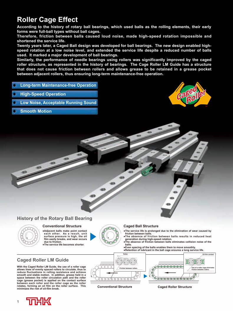
According to the history of rotary ball bearings, which used balls as the rolling elements, their early forms were full-ball types without ball cages. Therefore, friction between balls caused loud noise, made high-speed rotation impossible and shortened the service life.Twenty years later, a Caged Ball design was developed for ball bearings. The new design enabled high-speed rotation at a low noise level, and extended the service life despite a reduced number of balls used. It marked a major development of ball bearings. Similarly, the performance of needle bearings using rollers was significantly improved by the caged roller structure, as represented in the history of bearings. The Cage Roller LM Guide has a structure that does not cause friction between rollers and allows grease to be retained in a grease pocket between adjacent rollers, thus ensuring long-term maintenance-free operation.
History of the Rotary Ball Bearing
With the Caged Roller LM Guide, the use of a roller cage allows lines of evenly spaced rollers to circulate, thus to reduce fluctuations in rolling resistance and achieve smooth and stable motion. In addition, grease held in a space between the roller circulation path and the roller cage (grease pocket) is applied on the contact surface between each roller and the roller cage as the roller rotates, forming an oil film on the roller surface. This minimizes the risk of oil-film break. Conventional Structure Caged Roller Structure
Caged Roller LM GuideUse of a roller cage eliminatesfriction between rollers
Oil-film contact
Conventional Structure Adjacent balls make point contact
each other. As a result , unit surface pressure is high, the oil film easily breaks, and wear occurs due to friction.
The service life becomes shorter.
Caged Ball Structure The service life is prolonged due to the elimination of wear caused by
friction between balls. The absence of friction between balls results in reduced heat
generation during high-speed rotation. The absence of friction between balls eliminates collision noise of the
balls. Even spacing of the balls enables them to move smoothly. Retention of lubricant in the ball cage ensures a long service life.
Friction between rollers
Roller
Roller Cage Effect
Long-term Maintenance-free Operation
High-Speed Operation
Low Noise, Acceptable Running Sound
Smooth Motion
RollerRoller
508-0540_P01-12.indd 1 2015/09/11 15:36:51
2
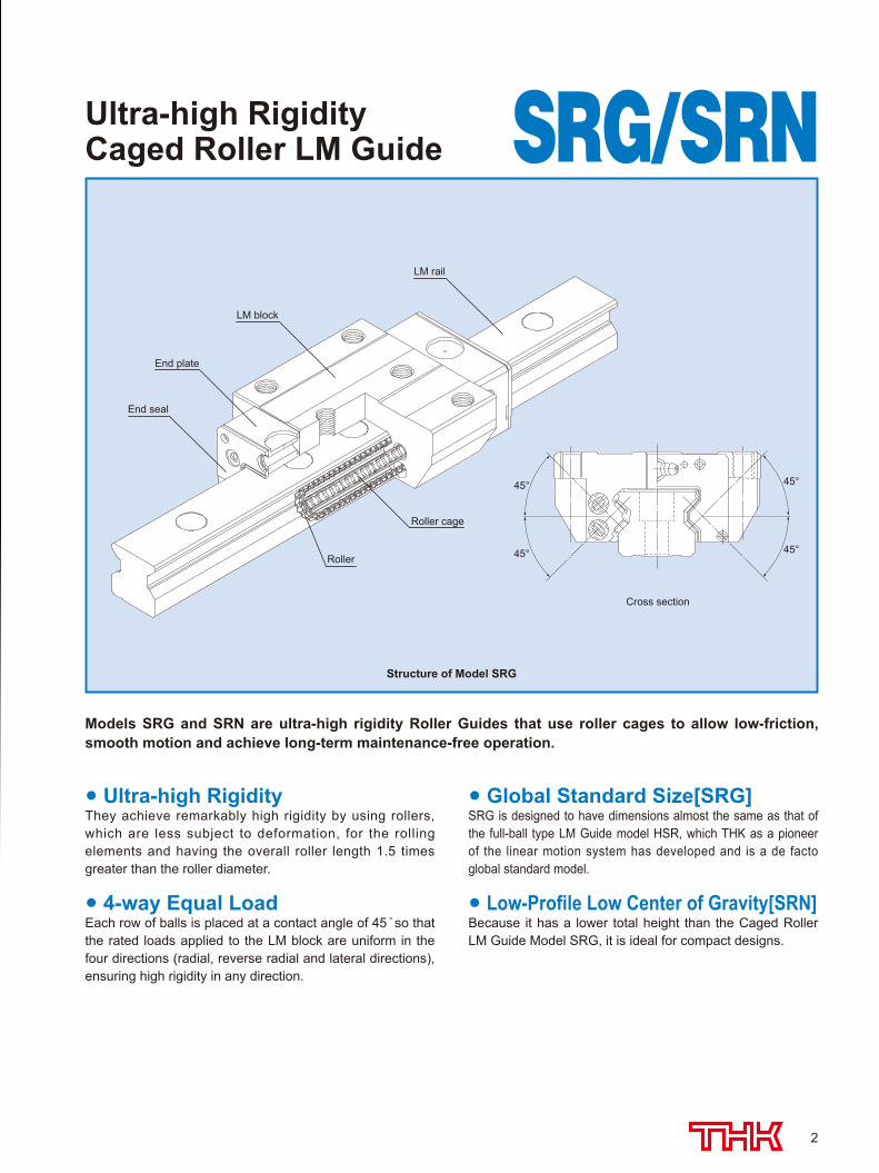
Cross section
LM block
LM rail
End plate
End seal
Roller cage
Roller
45°
45°
45°
45°
Ultra-high Rigidity Caged Roller LM Guide SRG/SRN
Structure of Model SRG
Models SRG and SRN are ultra-high rigidity Roller Guides that use roller cages to allow low-friction, smooth motion and achieve long-term maintenance-free operation.
Ultra-high RigidityThey achieve remarkably high rigidity by using rollers, which are less subject to deformation, for the rolling elements and having the overall roller length 1.5 times greater than the roller diameter.
4-way Equal LoadEach row of balls is placed at a contact angle of 45 so that the rated loads applied to the LM block are uniform in the four directions (radial, reverse radial and lateral directions), ensuring high rigidity in any direction.
Global Standard Size[SRG]SRG is designed to have dimensions almost the same as that of the full-ball type LM Guide model HSR, which THK as a pioneer of the linear motion system has developed and is a de facto global standard model.
Low-Profile Low Center of Gravity[SRN]Because it has a lower total height than the Caged Roller LM Guide Model SRG, it is ideal for compact designs.
508-0540_P01-12.indd 2 2015/09/11 15:36:52
3
0
2
4
6
8
10
12
0 5 10 15 20 25 30
Conventional roller guide #45
SRG45LC(with a caged roller)
Radial load (kN)D
efle
ctio
n(m
)
0
5
10
15
20
0 5 10 15 20 25 30
Conventional roller guide #45
Reverse-radial load (kN)
Def
lect
ion(
m)
SRG45LC(with a caged roller)
Table bolt fixed Bolt not fixed(free)
Horizontal load (kN)
0
10
20
30
40
0 5 10 15 20 25 30
#45
Def
lect
ion(
m)
SRG45LC(with a caged roller)
Conventional roller guide
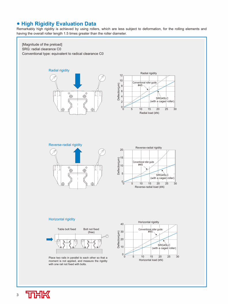
[Magnitude of the preload]SRG: radial clearance C0Conventional type: equivalent to radical clearance C0
Radial rigidityRadial rigidity
Reverse-radial rigidity
Horizontal rigidity
Reverse-radial rigidity
Horizontal rigidity
Place two rails in parallel to each other so that a moment is not applied, and measure the rigidity with one rail not fixed with bolts.
High Rigidity Evaluation DataRemarkably high rigidity is achieved by using rollers, which are less subject to deformation, for the rolling elements and having the overall roller length 1.5 times greater than the roller diameter.
508-0540_P01-12.indd 3 2015/09/11 15:36:52
4
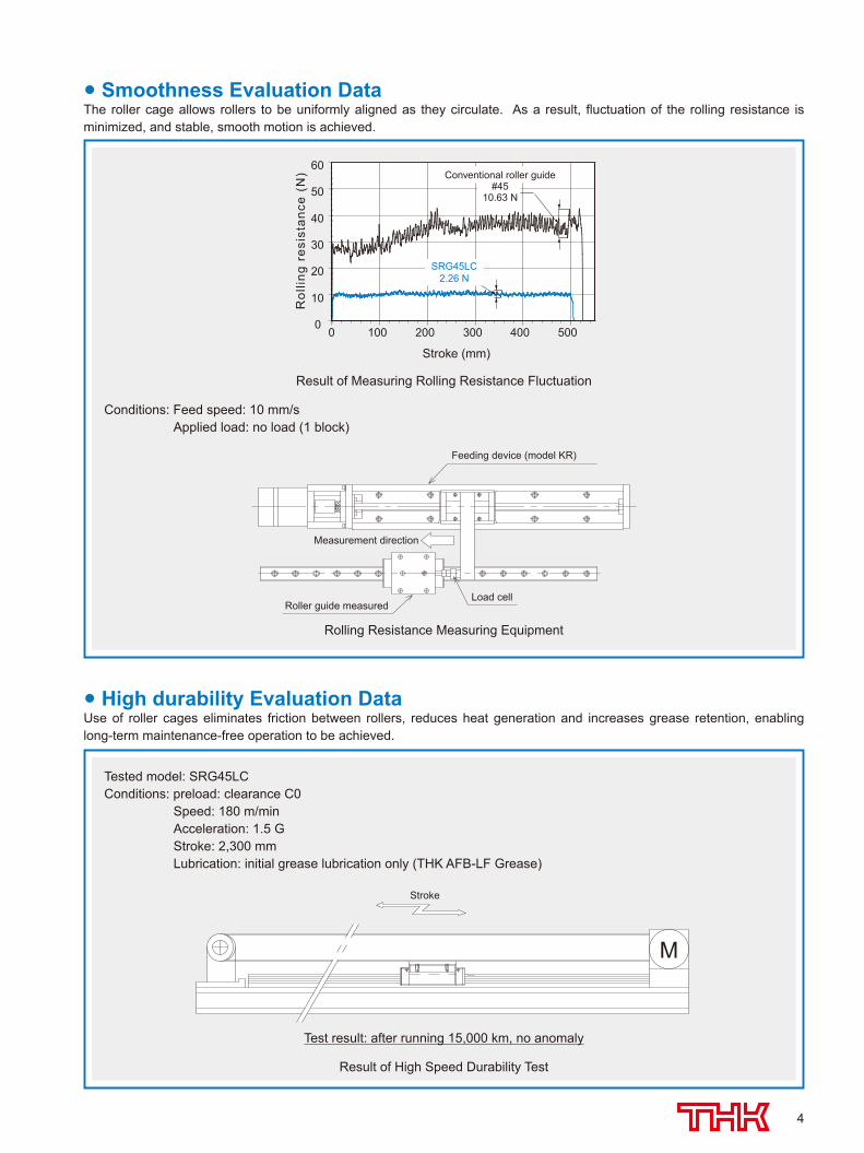
Smoothness Evaluation DataThe roller cage allows rollers to be uniformly aligned as they circulate. As a result, fluctuation of the rolling resistance is minimized, and stable, smooth motion is achieved.
Feeding device (model KR)
Roller guide measuredLoad cell
Measurement direction
Conditions: Feed speed: 10 mm/s Applied load: no load (1 block)
0
10
20
30
40
50
60
0 100 200 300 400 500
Stroke (mm)
Rol
ling
resi
stan
ce (
N)
SRG45LC2.26 N
Conventional roller guide#45
10.63 N
Result of Measuring Rolling Resistance Fluctuation
Rolling Resistance Measuring Equipment
Stroke
M
Test result: after running 15,000 km, no anomaly
Tested model: SRG45LCConditions: preload: clearance C0 Speed: 180 m/min Acceleration: 1.5 G Stroke: 2,300 mm Lubrication: initial grease lubrication only (THK AFB-LF Grease)
High durability Evaluation DataUse of roller cages eliminates friction between rollers, reduces heat generation and increases grease retention, enabling long-term maintenance-free operation to be achieved.
Result of High Speed Durability Test
508-0540_P01-12.indd 4 2015/09/11 15:36:52
5
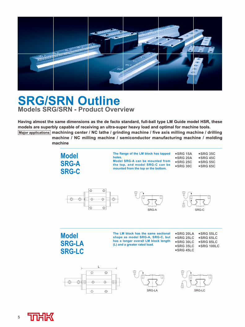
ModelSRG-ASRG-C
The flange of the LM block has tapped holes. .Model SRG-A can be mounted from the top, and model SRG-C can be mounted from the top or the bottom.
SRG 15A SRG 35CSRG 20A SRG 45CSRG 25C SRG 55CSRG 30C SRG 65C
ModelSRG-LASRG-LC
The LM block has the same sectional shape as model SRG-A, SRG-C, but has a longer overall LM block length (L) and a greater rated load.
SRG 20LA SRG 55LCSRG 25LC SRG 65LCSRG 30LC SRG 85LCSRG 35LC SRG 100LCSRG 45LC
L
SRG/SRN OutlineModels SRG/SRN - Product Overview
Having almost the same dimensions as the de facto standard, full-ball type LM Guide model HSR, these models are superbly capable of receiving an ultra-super heavy load and optimal for machine tools. Major applications machining center / NC lathe / grinding machine / five axis milling machine / drilling
machine / NC milling machine / semiconductor manufacturing machine / molding machine
SRG-A
SRG-LA
SRG-C
SRG-LC
508-0540_P01-12.indd 5 2015/09/11 15:36:53
6
SRG/SRN OUTLINEModels SRG/SRN - Product Overview
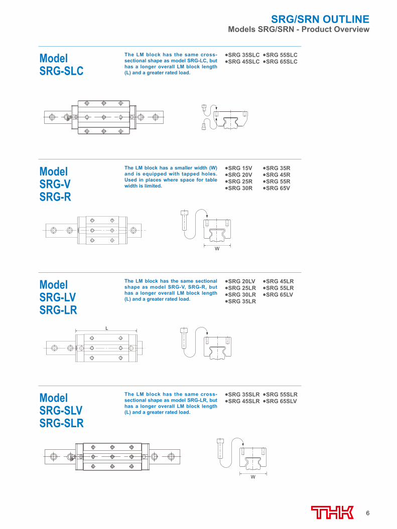
ModelSRG-SLC
The LM block has the same cross-sectional shape as model SRG-LC, but has a longer overall LM block length (L) and a greater rated load.
SRG 35SLC SRG 55SLCSRG 45SLC SRG 65SLC
ModelSRG-VSRG-R
The LM block has a smaller width (W) and is equipped with tapped holes. Used in places where space for table width is limited.
SRG 15V SRG 35RSRG 20V SRG 45RSRG 25R SRG 55RSRG 30R SRG 65V
W
ModelSRG-LVSRG-LR
The LM block has the same sectional shape as model SRG-V, SRG-R, but has a longer overall LM block length (L) and a greater rated load.
SRG 20LV SRG 45LRSRG 25LR SRG 55LRSRG 30LR SRG 65LVSRG 35LR
L
ModelSRG-SLVSRG-SLR
The LM block has the same cross-sectional shape as model SRG-LR, but has a longer overall LM block length (L) and a greater rated load.
SRG 35SLR SRG 55SLRSRG 45SLR SRG 65SLV
W
508-0540_P01-12.indd 6 2015/09/11 15:36:53
7
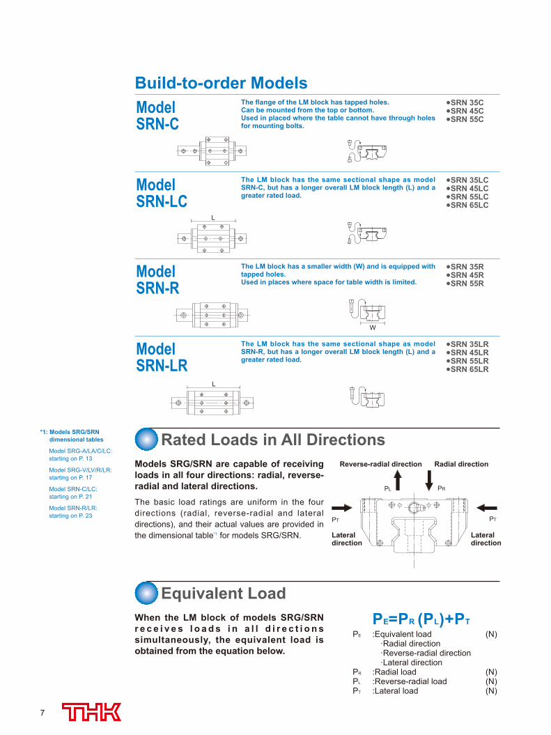
ModelSRN-C
The flange of the LM block has tapped holes.Can be mounted from the top or bottom. Used in placed where the table cannot have through holes for mounting bolts.
SRN 35CSRN 45CSRN 55C
ModelSRN-R
The LM block has a smaller width (W) and is equipped with tapped holes. Used in places where space for table width is limited.
SRN 35RSRN 45RSRN 55R
W
ModelSRN-LC
The LM block has the same sectional shape as model SRN-C, but has a longer overall LM block length (L) and a greater rated load.
SRN 35LCSRN 45LCSRN 55LCSRN 65LC
L
ModelSRN-LR
The LM block has the same sectional shape as model SRN-R, but has a longer overall LM block length (L) and a greater rated load.
SRN 35LRSRN 45LRSRN 55LRSRN 65LR
L
PE :Equivalent load (N) ·Radial direction ·Reverse-radial direction ·Lateral directionPR :Radial load (N)PL :Reverse-radial load (N)PT :Lateral load (N)
PE=PR (PL)+PT
Rated Loads in All Directions
Equivalent Load
Models SRG/SRN are capable of receiving loads in all four directions: radial, reverse-radial and lateral directions.The basic load ratings are uniform in the four directions (radial, reverse-radial and lateral directions), and their actual values are provided in the dimensional table*1 for models SRG/SRN.
When the LM block of models SRG/SRN r e c e i v e s l o a d s i n a l l d i r e c t i o n s simultaneously, the equivalent load is obtained from the equation below.
PT
PRPL
PT
Radial directionReverse-radial direction
Lateral direction
Lateral direction
Build-to-order Models
*1: Models SRG/SRN dimensional tables
Model SRG-A/LA/C/LC: starting on P. 13
Model SRG-V/LV/R/LR: starting on P. 17
Model SRN-C/LC: starting on P. 21
Model SRN-R/LR: starting on P. 23
508-0540_P01-12.indd 7 2015/09/11 15:36:53
8
SRG/SRN OUTLINEModels SRG/SRN - Product Overview
CPC
fH · fT · fC
fWL = ( · )3 100
10
Lh =L 106
2 RS n1 60
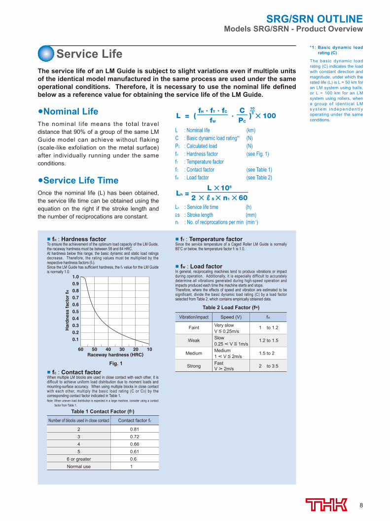
The service life of an LM Guide is subject to slight variations even if multiple units of the identical model manufactured in the same process are used under the same operational conditions. Therefore, it is necessary to use the nominal life defined below as a reference value for obtaining the service life of the LM Guide.
1.0
0.9
0.8
0.7
0.6
0.5
0.4
0.3
0.2
0.1
60 50 40 30 20 10Raceway hardness (HRC)
Har
dn
ess
fact
or
fH
Fig. 1
■ fH : Hardness factorTo ensure the achievement of the optimum load capacity of the LM Guide, the raceway hardness must be between 58 and 64 HRC.At hardness below this range, the basic dynamic and static load ratings decrease. Therefore, the rating values must be multiplied by the respective hardness factors (fH).Since the LM Guide has sufficient hardness, the fH value for the LM Guide is normally 1.0.
■ fC : Contact factorWhen multiple LM blocks are used in close contact with each other, it is difficult to achieve uniform load distribution due to moment loads and mounting-surface accuracy. When using multiple blocks in close contact with each other, multiply the basic load rating (C or C0) by the corresponding contact factor indicated in Table 1.Note: When uneven load distribution is expected in a large machine, consider using a contact
factor from Table 1.
■ fT : Temperature factorSince the service temperature of a Caged Roller LM Guide is normally 80°C or below, the temperature factor fT is 1.0.
■ fW : Load factorIn general, reciprocating machines tend to produce vibrations or impact during operation. Additionally, it is especially difficult to accurately determine all vibrations generated during high-speed operation and impacts produced each time the machine starts and stops. Therefore, where the effects of speed and vibration are estimated to be significant, divide the basic dynamic load rating (C) by a load factor selected from Table 2, which contains empirically obtained data.
Nominal LifeThe nominal l i fe means the total travel distance that 90% of a group of the same LM Guide model can achieve without flaking (scale-like exfoliation on the metal surface) after individually running under the same conditions.
Service Life TimeOnce the nominal life (L) has been obtained, the service life time can be obtained using the equation on the right if the stroke length and the number of reciprocations are constant.
L : Nominal life (km)C : Basic dynamic load rating*1 (N)PC : Calculated load (N)fH : Hardness factor (see Fig. 1)fT : Temperature factor fC : Contact factor (see Table 1)fW : Load factor (see Table 2)
Lh : Service life time (h)s : Stroke length (mm)
n1 : No. of reciprocations per min (min-1)
Table 1 Contact Factor (fC)
Table 2 Load Factor (fW)
Number of blocks used in close contact
2345
6 or greaterNormal use
Contact factor fC
0.810.720.660.610.61
Faint
Weak
Medium
Strong
Very slowV = 0.25m/sSlow0.25 < V = 1m/sMedium1 < V = 2m/sFastV > 2m/s
1 to 1.2
1.2 to 1.5
1.5 to 2
2 to 3.5
Vibration/impact Speed (V) fW
*1: Basic dynamic load rating (C)
The basic dynamic load rating (C) indicates the load with constant direction and magnitude, under which the rated life (L) is L = 50 km for an LM system using balls, or L = 100 km for an LM system using rollers, when a group of ident ical LM s y s t e m i n d e p e n d e n t l y operating under the same conditions.
Service Life
508-0540_P01-12.indd 8 2015/09/11 15:36:53
9
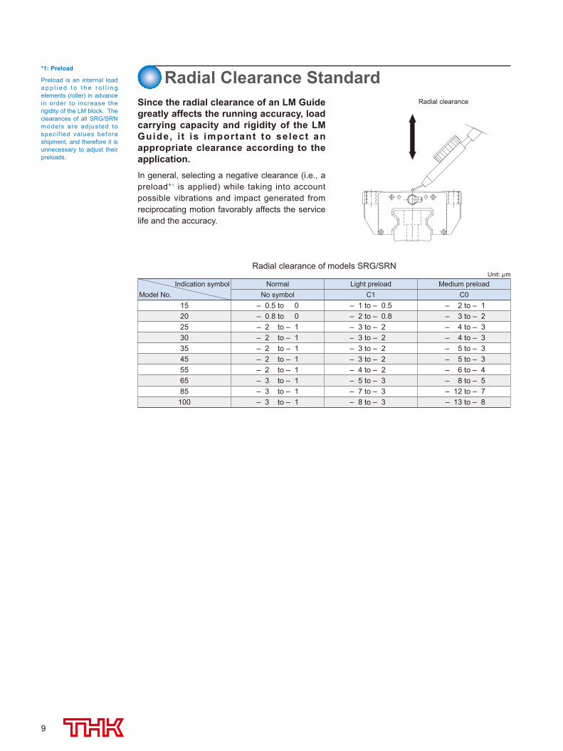
Radial clearance
*1: Preload
Preload is an internal load a p p l i e d t o t h e r o l l i n g elements (roller) in advance in order to increase the rigidity of the LM block. The clearances of all SRG/SRN models are adjusted to speci f ied values before shipment, and therefore it is unnecessary to adjust their preloads.
Radial Clearance StandardSince the radial clearance of an LM Guide greatly affects the running accuracy, load carrying capacity and rigidity of the LM Guide, i t is important to select an appropriate clearance according to the application.In general, selecting a negative clearance (i.e., a preload*1 is applied) while taking into account possible vibrations and impact generated from reciprocating motion favorably affects the service life and the accuracy.
Radial clearance of models SRG/SRNUnit: μm
Indication symbolModel No.
Normal Light preload Medium preloadNo symbol C1 C0
15 – 0.5 to 0 – 1 to – 0.5 – 2 to – 120 – 0.8 to 0 – 2 to – 0.8 – 3 to – 225 – 2 to – 1 – 3 to – 2 – 4 to – 330 – 2 to – 1 – 3 to – 2 – 4 to – 335 – 2 to – 1 – 3 to – 2 – 5 to – 345 – 2 to – 1 – 3 to – 2 – 5 to – 355 – 2 to – 1 – 4 to – 2 – 6 to – 465 – 3 to – 1 – 5 to – 3 – 8 to – 585 – 3 to – 1 – 7 to – 3 – 12 to – 7
100 – 3 to – 1 – 8 to – 3 – 13 to – 8
508-0540_P01-12.indd 9 2015/09/11 15:36:53
10
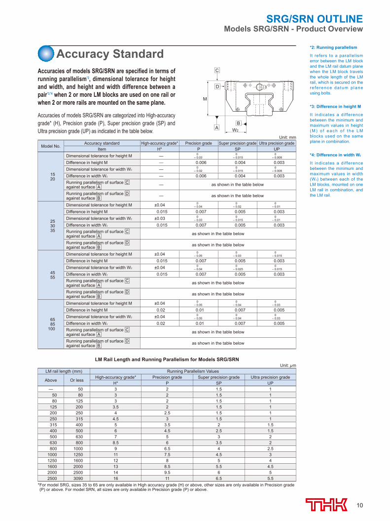
*2: Running parallelism
It refers to a parallelism error between the LM block and the LM rail datum plane when the LM block travels the whole length of the LM rail, which is secured on the re ference datum p lane using bolts.
*3: Difference in height M
I t indicates a difference between the minimum and maximum values in height (M) o f each o f t he LM blocks used on the same plane in combination.
*4: Difference in width W2
I t indicates a difference between the minimum and maximum values in width (W2) between each of the LM blocks, mounted on one LM rail in combination, and the LM rail.
Accuracies of models SRG/SRN are categorized into High-accuracy grade* (H), Precision grade (P), Super precision grade (SP) and Ultra precision grade (UP) as indicated in the table below.
Accuracy StandardAccuracies of models SRG/SRN are specified in terms of running parallelism*2, dimensional tolerance for height and width, and height and width difference between a pair*3,*4 when 2 or more LM blocks are used on one rail or when 2 or more rails are mounted on the same plane.
W2
M
A
D
C
B
LM Rail Length and Running Parallelism for Models SRG/SRNUnit: μm
LM rail length (mm) Running Parallelism Values
Above Or lessHigh-accuracy grade* Precision grade Super precision grade Ultra precision grade
H* P SP UP— 50 3 2 1.5 1
50 80 3 2 1.5 180 125 3 2 1.5 1
125 200 3.5 2 1.5 1200 250 4 2.5 1.5 1250 315 4.5 3 1.5 1315 400 5 3.5 2 1.5400 500 6 4.5 2.5 1.5500 630 7 5 3 2630 800 8.5 6 3.5 2800 1000 9 6.5 4 2.5
1000 1250 11 7.5 4.5 31250 1600 12 8 5 41600 2000 13 8.5 5.5 4.52000 2500 14 9.5 6 52500 3090 16 11 6.5 5.5
*For model SRG, sizes 35 to 65 are only available in High accuracy grade (H) or above, other sizes are only available in Precision grade (P) or above. For model SRN, all sizes are only available in Precision grade (P) or above.
Unit: mm
Model No.Accuracy standard High-accuracy grade* Precision grade Super precision grade Ultra precision grade
Item H* P SP UP
1520
Dimensional tolerance for height M — 0– 0.03
0– 0.015
0– 0.008
Difference in height M — 0.006 0.004 0.003Dimensional tolerance for width W2 — 0
– 0.020
– 0.0150
– 0.008
Difference in width W2 — 0.006 0.004 0.003Running parallelism of surface Cagainst surface A — as shown in the table below
Running parallelism of surface Dagainst surface B — as shown in the table below
253035
Dimensional tolerance for height M ±0.04 0– 0.04
0– 0.02
0– 0.01
Difference in height M 0.015 0.007 0.005 0.003Dimensional tolerance for width W2 ±0.03 0
– 0.030
– 0.0150
– 0.01
Difference in width W2 0.015 0.007 0.005 0.003Running parallelism of surface Cagainst surface A as shown in the table below
Running parallelism of surface Dagainst surface B as shown in the table below
4555
Dimensional tolerance for height M ±0.04 0– 0.05
0– 0.03
0– 0.015
Difference in height M 0.015 0.007 0.005 0.003Dimensional tolerance for width W2 ±0.04 0
– 0.040
– 0.0250
– 0.015
Difference in width W2 0.015 0.007 0.005 0.003Running parallelism of surface Cagainst surface A as shown in the table below
Running parallelism of surface Dagainst surface B as shown in the table below
6585
100
Dimensional tolerance for height M ±0.04 0– 0.05
0– 0.04
0– 0.03
Difference in height M 0.02 0.01 0.007 0.005Dimensional tolerance for width W2 ±0.04 0
– 0.050
– 0.040
– 0.03
Difference in width W2 0.02 0.01 0.007 0.005Running parallelism of surface Cagainst surface A as shown in the table below
Running parallelism of surface Dagainst surface B as shown in the table below
SRG/SRN OUTLINEModels SRG/SRN - Product Overview
508-0540_P01-12.indd 10 2015/09/11 15:36:53
11
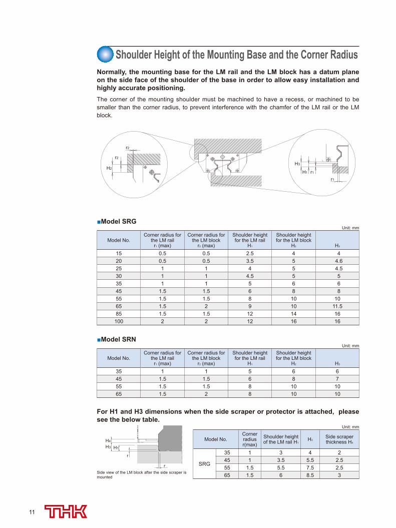
Normally, the mounting base for the LM rail and the LM block has a datum plane on the side face of the shoulder of the base in order to allow easy installation and highly accurate positioning. The corner of the mounting shoulder must be machined to have a recess, or machined to be smaller than the corner radius, to prevent interference with the chamfer of the LM rail or the LM block.
For H1 and H3 dimensions when the side scraper or protector is attached, please see the below table.
Shoulder Height of the Mounting Base and the Corner Radius
r2
r2
H2
r1
r1H1
H3
■Model SRGUnit: mm
Model No.Corner radius for
the LM rail r1 (max)
Corner radius for the LM block
r2 (max)
Shoulder height for the LM rail
H1
Shoulder height for the LM block
H2 H3
15 0.5 0.5 2.5 4 0420 0.5 0.5 3.5 5 04.625 1 1 4 5 04.530 1 1 4.5 5 0535 1 1 5 6 0645 1.5 1.5 6 8 0855 1.5 1.5 8 10 1065 1.5 2 9 10 11.585 1.5 1.5 12 14 16
100 2 2 12 16 16
■Model SRNUnit: mm
Model No.Corner radius for
the LM rail r1 (max)
Corner radius for the LM block
r2 (max)
Shoulder height for the LM rail
H1
Shoulder height for the LM block
H2 H3
35 1 1 5 6 645 1.5 1.5 6 8 755 1.5 1.5 8 10 1065 1.5 2 8 10 10
Unit: mm
Model No.Corner radiusr(max)
Shoulder height of the LM rail H1
H3Side scraper thickness H4
SRG
35 1 3 4 245 1 3.5 5.5 2.555 1.5 5.5 7.5 2.565 1.5 6 8.5 3Side view of the LM block after the side scraper is
mounted
H3
H4
H1
r
r
508-0540_P01-12.indd 11 2015/09/11 15:36:53
12
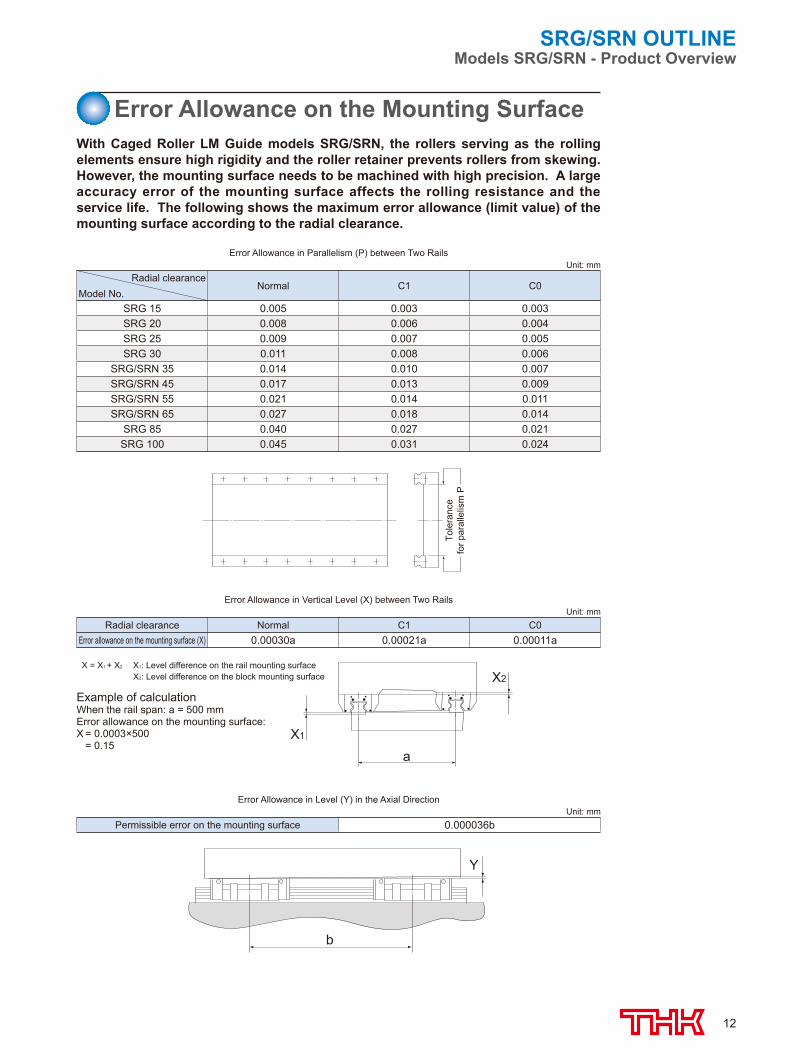
Error Allowance on the Mounting SurfaceWith Caged Roller LM Guide models SRG/SRN, the rollers serving as the rolling elements ensure high rigidity and the roller retainer prevents rollers from skewing. However, the mounting surface needs to be machined with high precision. A large accuracy error of the mounting surface affects the rolling resistance and the service life. The following shows the maximum error allowance (limit value) of the mounting surface according to the radial clearance.
b
Y
Tole
ranc
efo
r par
alle
lism
P
X2
aX1
X = X1 + X2 X1: Level difference on the rail mounting surface X2: Level difference on the block mounting surface
Example of calculationWhen the rail span: a = 500 mmError allowance on the mounting surface: X = 0.0003×500 = 0.15
SRG/SRN OUTLINEModels SRG/SRN - Product Overview
Error Allowance in Parallelism (P) between Two RailsUnit: mm
Radial clearanceModel No.
Normal C1 C0
SRG 15 0.005 0.003 0.003SRG 20 0.008 0.006 0.004SRG 25 0.009 0.007 0.005SRG 30 0.011 0.008 0.006
SRG/SRN 35 0.014 0.010 0.007SRG/SRN 45 0.017 0.013 0.009SRG/SRN 55 0.021 0.014 0.011SRG/SRN 65 0.027 0.018 0.014
SRG 85 0.040 0.027 0.021SRG 100 0.045 0.031 0.024
Error Allowance in Vertical Level (X) between Two RailsUnit: mm
Radial clearance Normal C1 C0Error allowance on the mounting surface (X) 0.00030a 0.00021a 0.00011a
Error Allowance in Level (Y) in the Axial DirectionUnit: mm
Permissible error on the mounting surface 0.000036b
508-0540_P01-12.indd 12 2015/09/11 15:36:54

13
(E)
4-S×ℓ1(φ H) C
C2 2-S×ℓ2
(φ H)
B
Models SRG15A and 20A/LA
W
TM
W1W2
(K)H3
M1h
N
φ d1
φ d2
F
**4-φ D0e0
f0L1L
Symbol for LM rail jointed use
LM rail length(in mm)
With QZLubricator
Contamination protectionaccessory symbol
Accuracy symbolHigh-accuracy grade (H)Precision grade (P)/Super precision grade (SP)Ultra precision grade (UP)
Radial clearance symbolNormal (No symbol)Light preload (C1)Medium preload (C0)
No. of LM blocksused on the same rail
Type ofLM block
Model number
Symbol for No. of rails used on the same plane
With plate cover
SRG30 LC 2 QZ TTHH C0 +1200L P Z T -
Models SRG-A/C and LA/LC (15-30)
Note) This model number indicates that a single-rail unit constitutes one set. (i.e., required number of sets when 2 rails are used in parallel is 2 at a minimum.) Those models equipped with QZ Lubricator cannot have a grease nipple. When desiring a grease nipple for a model attached with QZ, contact THK.
Model No.
Outer dimensions LM block dimensions
Height Width LengthGrease nipple
M W L B C C2 S H ℓ1 ℓ2 L1 T T1 K N E e0 f0 D0
SRG 15A 24 47 69.2 38 30 26 M5 (4.3) 8 7.5 45 7 (8) 20 4 4.5 4 6 2.9 PB107
SRG 20ASRG 20LA 30 63 86.2
106.2 53 40 35 M6 (5.4) 10 9 5878 10 (10) 25.4 5 4.5 4 6 2.9 PB107
SRG 25CSRG 25LC 36 70 95.5
115.1 57 45 40 M8 6.8 — — 65.585.1 9.5 10 31.5 5.5 12 6 6.4 5.2 B-M6F
SRG 30CSRG 30LC 42 90 111
135 72 52 44 M10 8.5 — — 7599 12 14 37 6.5 12 6 7.5 5.2 B-M6F
Size
15 20 25 30
35 45 55 65
85 100
Model number coding
508-0540_P13-24.indd 13 2015/09/11 11:45:44
14
6-S(φ H through)
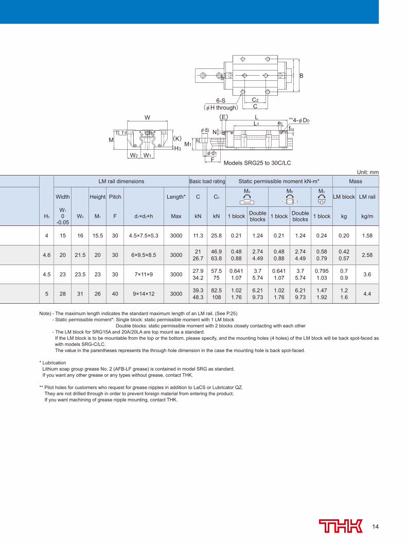
Models SRG25 to 30C/LC
B
C2C
**4-φ D0L1L
e0
f0
φ d1
F
φ d2 N
M1h
W1W2
W
(K)H3
MT T1
(E)
LM rail dimensions Basic load rating Static permissible moment kN-m* Mass
Width Height Pitch Length* C C0
MA MB MC
LM block LM rail
H3
W1
0-0.05
W2 M1 F d1×d2×h Max kN kN 1 block Double blocks 1 block Double
blocks 1 block kg kg/m
4 15 16 15.5 30 4.5×7.5×5.3 3000 11.3 25.8 0.21 1.24 0.21 1.24 0.24 0.20 1.58
4.6 20 21.5 20 30 6×9.5×8.5 3000 2126.7
46.963.8
0.480.88
2.744.49
0.480.88
2.744.49
0.580.79
0.420.57 2.58
4.5 23 23.5 23 30 7×11×9 3000 27.934.2
57.575
0.6411.07
3.75.74
0.6411.07
3.75.74
0.7951.03
0.70.9 3.6
5 28 31 26 40 9×14×12 3000 39.348.3
82.5108
1.021.76
6.219.73
1.021.76
6.219.73
1.471.92
1.21.6 4.4
Unit: mm
Note) - The maximum length indicates the standard maximum length of an LM rail. (See P.25) - Static permissible moment*: Single block: static permissible moment with 1 LM block Double blocks: static permissible moment with 2 blocks closely contacting with each other - The LM block for SRG15A and 20A/20LA are top mount as a standard.
If the LM block is to be mountable from the top or the bottom, please specify, and the mounting holes (4 holes) of the LM block will be back spot-faced as with models SRG-C/LC.
The value in the parentheses represents the through hole dimension in the case the mounting hole is back spot-faced.
* Lubrication Lithium soap group grease No. 2 (AFB-LF grease) is contained in model SRG as standard. If you want any other grease or any types without grease, contact THK.
** Pilot holes for customers who request for grease nipples in addition to LaCS or Lubricator QZ. They are not drilled through in order to prevent foreign material from entering the product. If you want machining of grease nipple mounting, contact THK.
508-0540_P13-24.indd 14 2015/09/11 11:45:45
15
Symbol for LM rail jointed use
LM rail length(in mm)
With QZLubricator
Contamination protectionaccessory symbol
Accuracy symbolHigh accuracy grade (H)Precision grade (P)/Super precision grade (SP)Ultra precision grade (UP)
Radial clearance symbolNormal (No symbol)Light preload (C1)Medium preload (C0)
No. of LM blocksused on the same rail
Type ofLM block
Model number
Symbol for No. of rails used on the same plane
With plate cover
SRG45 LC 2 QZ TTHH C0 +1200L P Z T -
6-S(φ H through)
Models SRG35 to 65C/LC
B
C2C
**4-φ D0L1L
e0
f0
φ d1
F
φ d2 N
M1h
W1W2
W
(K)H3
MT T1
(E)
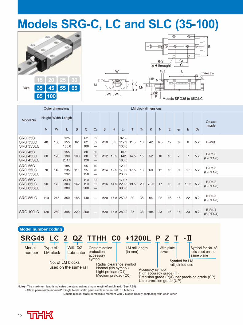
Models SRG-C, LC and SLC (35-100)
Model No.
Outer dimensions LM block dimensions
Height Width LengthGrease nipple
M W L B C C2 S H L1 T T1 K N E e0 f0 D0
SRG 35CSRG 35LCSRG 35SLC
48 100125155
180.882
6262100
5252—
M10 8.582.2112.2138.0
11.5 10 42 6.5 12 6 6 5.2 B-M6F
SRG 45CSRG 45LCSRG 45SLC
60 120155190
231.5100
8080120
6060—
M12 10.5107142
183.514.5 15 52 10 16 7 7 5.2 B-R1/8
(B-PT1/8)
SRG 55CSRG 55LCSRG 55SLC
70 140185235292
1169595150
7070—
M14 12.5129.2179.2236.2
17.5 18 60 12 16 9 8.5 5.2 B-R1/8(B-PT1/8)
SRG 65CSRG 65LCSRG 65SLC
90 170244.9303380
142110110200
8282—
M16 14.5171.7229.8306.8
19.5 20 78.5 17 16 9 13.5 5.2 B-R1/8(B-PT1/8)
SRG 85LC 110 215 350 185 140 — M20 17.8 250.8 30 35 94 22 16 15 22 8.2 B-R1/8(B-PT1/8)
SRG 100LC 120 250 395 220 200 — M20 17.8 280.2 35 38 104 23 16 15 23 8.2 B-R1/4(B-PT1/4)
Model number coding
Note) - The maximum length indicates the standard maximum length of an LM rail. (See P.25) - Static permissible moment*: Single block: static permissible moment with 1 LM block Double blocks: static permissible moment with 2 blocks closely contacting with each other
Size
15 20 25 30
35 45 55 65
85 100
508-0540_P13-24.indd 15 2015/09/11 11:45:46
16
f0
T T1
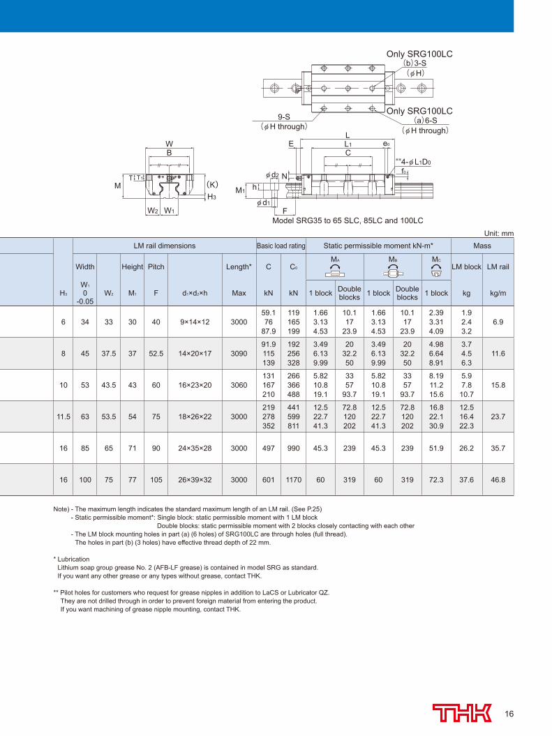
Model SRG35 to 65 SLC, 85LC and 100LC
N
M1
φ d1
φ d2
h
F
M (K)H3
W
W1W2
B**4-φ L1D0
(b)3-S
E L1L
C
9-S(φ H through)
Only SRG100LC
Only SRG100LC
(φ H)
(a)6-S(φ H through)
e0
LM rail dimensions Basic load rating Static permissible moment kN-m* Mass
Width Height Pitch Length* C C0
MA MB MC
LM block LM rail
H3
W1
0-0.05
W2 M1 F d1×d2×h Max kN kN 1 block Double blocks 1 block Double
blocks 1 block kg kg/m
6 34 33 30 40 9×14×12 300059.176
87.9
119165199
1.663.134.53
10.117
23.9
1.663.134.53
10.117
23.9
2.393.314.09
1.92.43.2
6.9
8 45 37.5 37 52.5 14×20×17 309091.9115139
192256328
3.496.139.99
2032.250
3.496.139.99
2032.250
4.986.648.91
3.74.56.3
11.6
10 53 43.5 43 60 16×23×20 3060131167210
266366488
5.8210.819.1
3357
93.7
5.8210.819.1
3357
93.7
8.1911.215.6
5.97.810.7
15.8
11.5 63 53.5 54 75 18×26×22 3000219278352
441599811
12.522.741.3
72.8120202
12.522.741.3
72.8120202
16.822.130.9
12.516.422.3
23.7
16 85 65 71 90 24×35×28 3000 497 990 45.3 239 45.3 239 51.9 26.2 35.7
16 100 75 77 105 26×39×32 3000 601 1170 60 319 60 319 72.3 37.6 46.8
Unit: mm
Note) - The maximum length indicates the standard maximum length of an LM rail. (See P.25) - Static permissible moment*: Single block: static permissible moment with 1 LM block Double blocks: static permissible moment with 2 blocks closely contacting with each other - The LM block mounting holes in part (a) (6 holes) of SRG100LC are through holes (full thread). The holes in part (b) (3 holes) have effective thread depth of 22 mm.
* Lubrication Lithium soap group grease No. 2 (AFB-LF grease) is contained in model SRG as standard. If you want any other grease or any types without grease, contact THK.
** Pilot holes for customers who request for grease nipples in addition to LaCS or Lubricator QZ. They are not drilled through in order to prevent foreign material from entering the product. If you want machining of grease nipple mounting, contact THK.
508-0540_P13-24.indd 16 2015/09/11 11:45:46
17
LM rail length(in mm)
With QZLubricator
Contamination protectionaccessory symbol
Accuracy symbolHigh accuracy grade (H)Precision grade (P)/Super precision grade (SP)Ultra precision grade (UP)
Radial clearance symbolNormal (No symbol)Light preload (C1)Medium preload (C0)
No. of LM blocksused on the same rail
Type ofLM block
Model number
Symbol for LM rail jointed use
Symbol for No. of rails used on the same plane
With plate cover
SRG30 LR 2 QZ TTHH C0 +1200L P Z T -
B
2-S×ℓ2C4-S×ℓ1
L(E)**4-φ D0L1 e0
Nφ d2
W
(K)H3
M1h
Fφ d1
f0
W1W2
TM
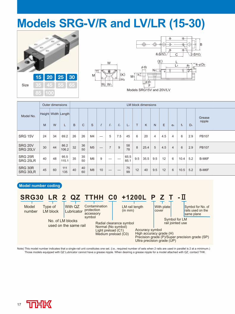
Models SRG15V and 20V/LV
Models SRG-V/R and LV/LR (15-30)
Model No.
Outer dimensions LM block dimensions
Height Width LengthGrease nipple
M W L B C S ℓ ℓ1 ℓ2 L1 T K N E e0 f0 D0
SRG 15V 24 34 69.2 26 26 M4 — 5 7.5 45 6 20 4 4.5 4 6 2.9 PB107
SRG 20VSRG 20LV 30 44 86.2
106.2 32 3650 M5 — 7 9 58
78 8 25.4 5 4.5 4 6 2.9 PB107
SRG 25RSRG 25LR 40 48 95.5
115.1 35 3550 M6 9 — — 65.5
85.1 9.5 35.5 9.5 12 6 10.4 5.2 B-M6F
SRG 30RSRG 30LR 45 60 111
135 40 4060 M8 10 — — 75
99 12 40 9.5 12 6 10.5 5.2 B-M6F
Size
15 20 25 30
35 45 55 65
85 100
Model number coding
Note) This model number indicates that a single-rail unit constitutes one set. (i.e., required number of sets when 2 rails are used in parallel is 2 at a minimum.) Those models equipped with QZ Lubricator cannot have a grease nipple. When desiring a grease nipple for a model attached with QZ, contact THK.
508-0540_P13-24.indd 17 2015/09/11 11:45:47
18
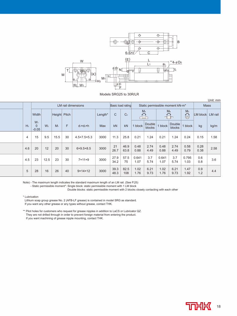
Models SRG25 to 30R/LR
B
6-S×ℓ
L1
L **4-φ D0
f0
e0
(E)
φ d2 N
φ d1F
M1hM
T
W
(K)
H3
W1W2
C
LM rail dimensions Basic load rating Static permissible moment kN-m* Mass
Width Height Pitch Length* C C0
MA MB MC
LM block LM rail
H3
W1
0-0.05
W2 M1 F d1×d2×h Max kN kN 1 block Double blocks 1 block Double
blocks 1 block kg kg/m
4 15 9.5 15.5 30 4.5×7.5×5.3 3000 11.3 25.8 0.21 1.24 0.21 1.24 0.24 0.15 1.58
4.6 20 12 20 30 6×9.5×8.5 3000 2126.7
46.963.8
0.480.88
2.744.49
0.480.88
2.744.49
0.580.79
0.280.38 2.58
4.5 23 12.5 23 30 7×11×9 3000 27.934.2
57.575
0.6411.07
3.75.74
0.6411.07
3.75.74
0.7951.03
0.60.8 3.6
5 28 16 26 40 9×14×12 3000 39.348.3
82.5108
1.021.76
6.219.73
1.021.76
6.219.73
1.471.92
0.91.2 4.4
Unit: mm
Note) - The maximum length indicates the standard maximum length of an LM rail. (See P.25) - Static permissible moment*: Single block: static permissible moment with 1 LM block Double blocks: static permissible moment with 2 blocks closely contacting with each other
* Lubrication Lithium soap group grease No. 2 (AFB-LF grease) is contained in model SRG as standard. If you want any other grease or any types without grease, contact THK.
** Pilot holes for customers who request for grease nipples in addition to LaCS or Lubricator QZ. They are not drilled through in order to prevent foreign material from entering the product. If you want machining of grease nipple mounting, contact THK.
508-0540_P13-24.indd 18 2015/09/11 11:45:47
19
LM rail length(in mm)
With QZLubricator
Contamination protectionaccessory symbol
Accuracy symbolHigh accuracy grade (H)Precision grade (P)/Super precision grade (SP)Ultra precision grade (UP)
Radial clearance symbolNormal (No symbol)Light preload (C1)Medium preload (C0)
No. of LM blocksused on the same rail
Type ofLM block
Model number
Symbol for LM rail jointed use
Symbol for No. of rails used on the same plane
With plate cover
SRG45 LR 2 QZ TTHH C0 +1200L P Z T -
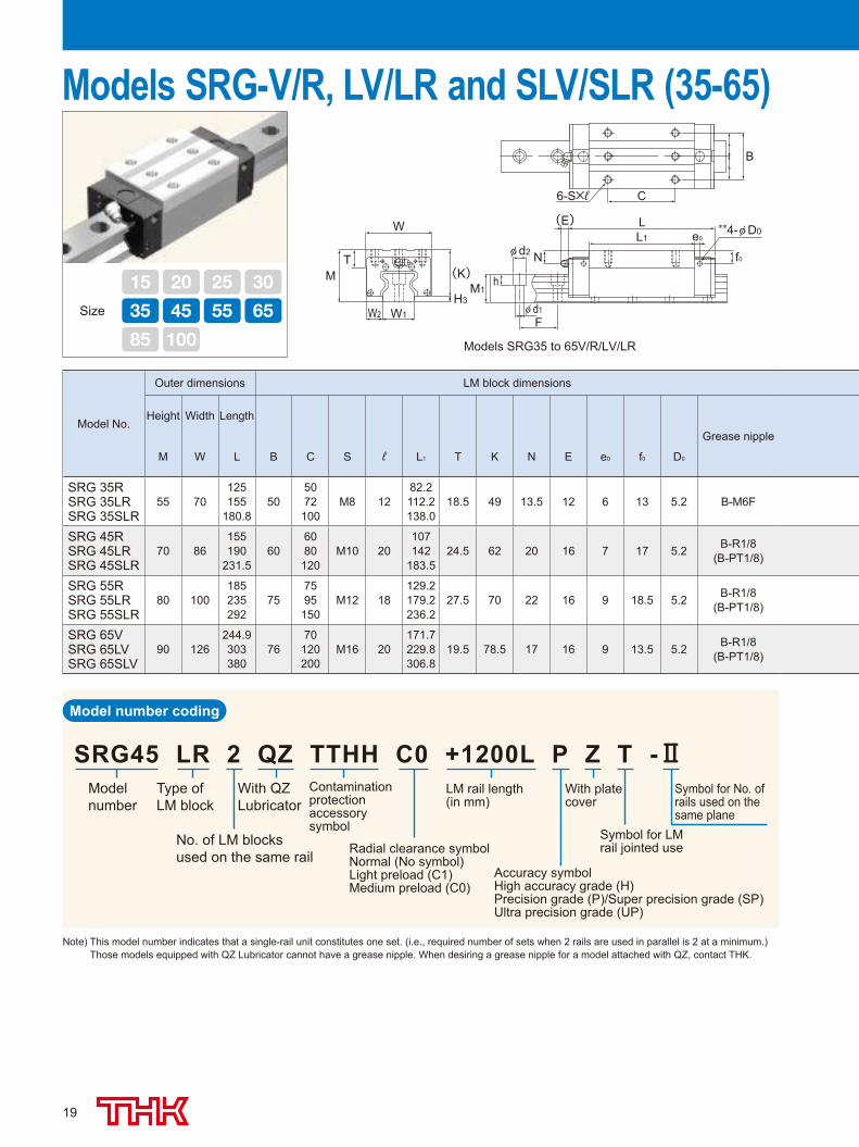
Models SRG35 to 65V/R/LV/LR
B
6-S×ℓ
L1
L **4-φ D0
f0
e0
(E)
φ d2 N
φ d1F
M1hM
T
W
(K)
H3
W1W2
C
Models SRG-V/R, LV/LR and SLV/SLR (35-65)
Model No.
Outer dimensions LM block dimensions
Height Width Length
Grease nipple
M W L B C S ℓ L1 T K N E e0 f0 D0
SRG 35RSRG 35LRSRG 35SLR
55 70125155
180.850
5072100
M8 1282.2112.2138.0
18.5 49 13.5 12 6 13 5.2 B-M6F
SRG 45RSRG 45LRSRG 45SLR
70 86155190
231.560
6080120
M10 20107142
183.524.5 62 20 16 7 17 5.2 B-R1/8
(B-PT1/8)
SRG 55RSRG 55LRSRG 55SLR
80 100185235292
757595150
M12 18129.2179.2236.2
27.5 70 22 16 9 18.5 5.2 B-R1/8(B-PT1/8)
SRG 65VSRG 65LVSRG 65SLV
90 126244.9303380
7670120200
M16 20171.7229.8306.8
19.5 78.5 17 16 9 13.5 5.2 B-R1/8(B-PT1/8)
Size
15 20 25 30
35 45 55 65
85 100
Model number coding
Note) This model number indicates that a single-rail unit constitutes one set. (i.e., required number of sets when 2 rails are used in parallel is 2 at a minimum.) Those models equipped with QZ Lubricator cannot have a grease nipple. When desiring a grease nipple for a model attached with QZ, contact THK.
508-0540_P13-24.indd 19 2015/09/11 11:45:47
20
H3
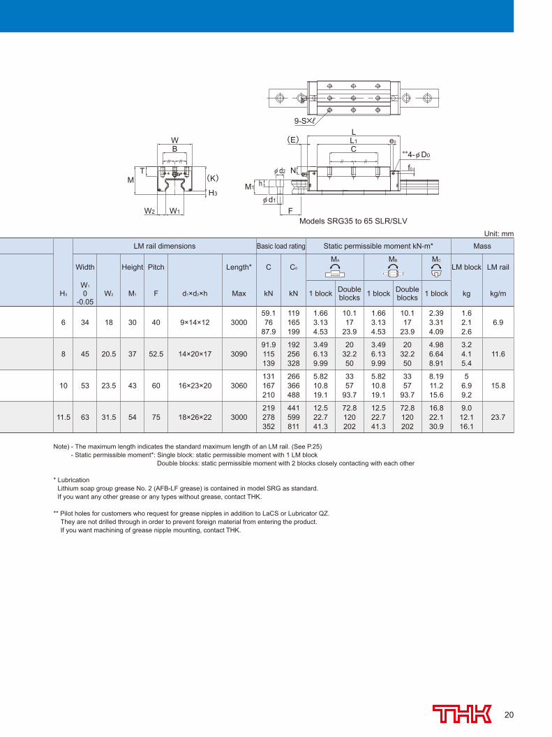
Models SRG35 to 65 SLR/SLV
(E)
F
L1C
L
(K)
BW
MT
M1 h
φ d2 N
**4-φ D0
φ d1
W1W2
9-S×ℓ
e0
f0
LM rail dimensions Basic load rating Static permissible moment kN-m* Mass
Width Height Pitch Length* C C0
MA MB MC
LM block LM rail
H3
W1
0-0.05
W2 M1 F d1×d2×h Max kN kN 1 block Double blocks 1 block Double
blocks 1 block kg kg/m
6 34 18 30 40 9×14×12 300059.176
87.9
119165199
1.663.134.53
10.117
23.9
1.663.134.53
10.117
23.9
2.393.314.09
1.62.12.6
6.9
8 45 20.5 37 52.5 14×20×17 309091.9115139
192256328
3.496.139.99
2032.250
3.496.139.99
2032.250
4.986.648.91
3.24.15.4
11.6
10 53 23.5 43 60 16×23×20 3060131167210
266366488
5.8210.819.1
3357
93.7
5.8210.819.1
3357
93.7
8.1911.215.6
56.99.2
15.8
11.5 63 31.5 54 75 18×26×22 3000219278352
441599811
12.522.741.3
72.8120202
12.522.741.3
72.8120202
16.822.130.9
9.012.116.1
23.7
Unit: mm
Note) - The maximum length indicates the standard maximum length of an LM rail. (See P.25) - Static permissible moment*: Single block: static permissible moment with 1 LM block Double blocks: static permissible moment with 2 blocks closely contacting with each other
* Lubrication Lithium soap group grease No. 2 (AFB-LF grease) is contained in model SRG as standard. If you want any other grease or any types without grease, contact THK.
** Pilot holes for customers who request for grease nipples in addition to LaCS or Lubricator QZ. They are not drilled through in order to prevent foreign material from entering the product. If you want machining of grease nipple mounting, contact THK.
508-0540_P13-24.indd 20 2015/09/11 11:45:48
21
LM rail length(in mm)
Contamination protectionaccessory symbol
With QZ lubricator
Accuracy symbolPrecision grade (P)/Super precision grade (SP)Ultra precision grade (UP)
Radial clearance symbolNormal (No symbol)Light preload (C1)Medium preload (C0)
No. of LM blocksused on the same rail
Type ofLM block
Model number
Symbol for No. of rails used on the same plane
Symbol for LM railjointed use
With plate cover
SRN45 C 2 QZ KK C0 +1160L P Z T -
W
M
W1 W2
T1 T
(K)
H3
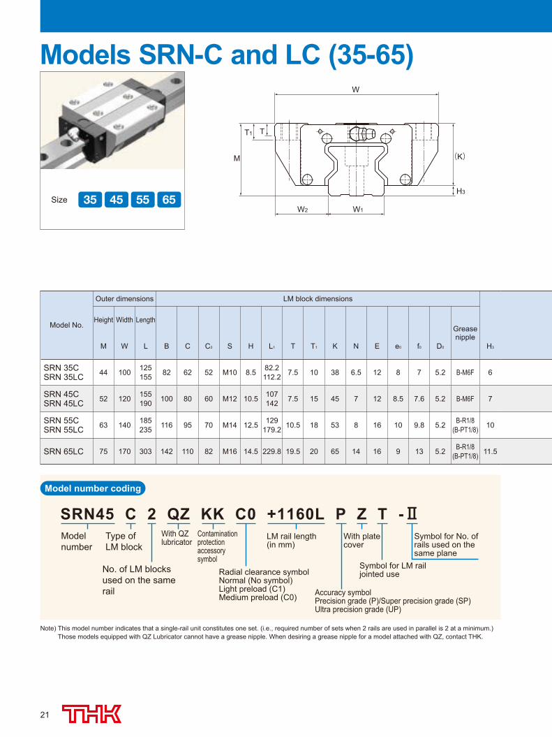
Models SRN-C and LC (35-65)
Model No.
Outer dimensions LM block dimensions
Height Width LengthGrease nipple
M W L B C C2 S H L1 T T1 K N E e0 f0 D0 H3
SRN 35CSRN 35LC 44 100 125
155 82 62 52 M10 8.5 82.2112.2 7.5 10 38 6.5 12 8 7 5.2 B-M6F 6
SRN 45CSRN 45LC 52 120 155
190 100 80 60 M12 10.5 107142 7.5 15 45 7 12 8.5 7.6 5.2 B-M6F 7
SRN 55CSRN 55LC 63 140 185
235 116 95 70 M14 12.5 129179.2 10.5 18 53 8 16 10 9.8 5.2 B-R1/8
(B-PT1/8) 10
SRN 65LC 75 170 303 142 110 82 M16 14.5 229.8 19.5 20 65 14 16 9 13 5.2 B-R1/8(B-PT1/8) 11.5
Size
15 20 25 30
35 45 55 65
85 100
Model number coding
Note) This model number indicates that a single-rail unit constitutes one set. (i.e., required number of sets when 2 rails are used in parallel is 2 at a minimum.) Those models equipped with QZ Lubricator cannot have a grease nipple. When desiring a grease nipple for a model attached with QZ, contact THK.
508-0540_P13-24.indd 21 2015/09/11 11:45:48
22
(φ H through)
φ d2
**4-φ D0
φ d1
M1
e0
f0
L1 L
B
F
h N
(E)
C2 C
6-S
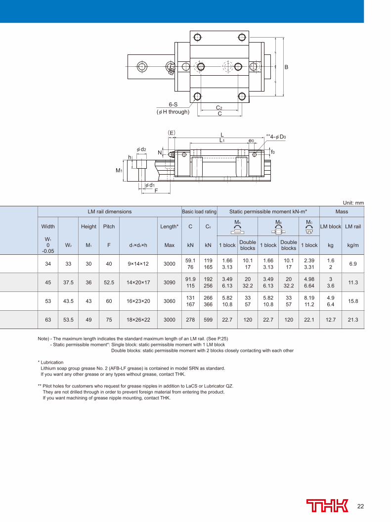
LM rail dimensions Basic load rating Static permissible moment kN-m* Mass
Width Height Pitch Length* C C0
MA MB MC
LM block LM rail
W1
0-0.05
W2 M1 F d1×d2×h Max kN kN 1 block Double blocks 1 block Double
blocks 1 block kg kg/m
34 33 30 40 9×14×12 3000 59.176
119165
1.663.13
10.117
1.663.13
10.117
2.393.31
1.62 6.9
45 37.5 36 52.5 14×20×17 3090 91.9115
192256
3.496.13
2032.2
3.496.13
2032.2
4.986.64
33.6 11.3
53 43.5 43 60 16×23×20 3060 131167
266366
5.8210.8
3357
5.8210.8
3357
8.1911.2
4.96.4 15.8
63 53.5 49 75 18×26×22 3000 278 599 22.7 120 22.7 120 22.1 12.7 21.3
Unit: mm
Note) - The maximum length indicates the standard maximum length of an LM rail. (See P.25) - Static permissible moment*: Single block: static permissible moment with 1 LM block Double blocks: static permissible moment with 2 blocks closely contacting with each other
* Lubrication Lithium soap group grease No. 2 (AFB-LF grease) is contained in model SRN as standard. If you want any other grease or any types without grease, contact THK.
** Pilot holes for customers who request for grease nipples in addition to LaCS or Lubricator QZ. They are not drilled through in order to prevent foreign material from entering the product. If you want machining of grease nipple mounting, contact THK.
508-0540_P13-24.indd 22 2015/09/11 11:45:49
23
LM rail length(in mm)
Contamination protectionaccessory symbol
With QZ lubricator
Accuracy symbolPrecision grade (P)/Super precision grade (SP)Ultra precision grade (UP)
Radial clearance symbolNormal (No symbol)Light preload (C1)Medium preload (C0)
No. of LM blocksused on the same rail
Type ofLM block
Model number
Symbol for LM railjointed use
Symbol for No. of rails used on the same plane
With plate cover
SRN45 LR 2 QZ KK C0 +1200L P Z T -
W
(K)
H3
M
T
W1 W2
Model number coding
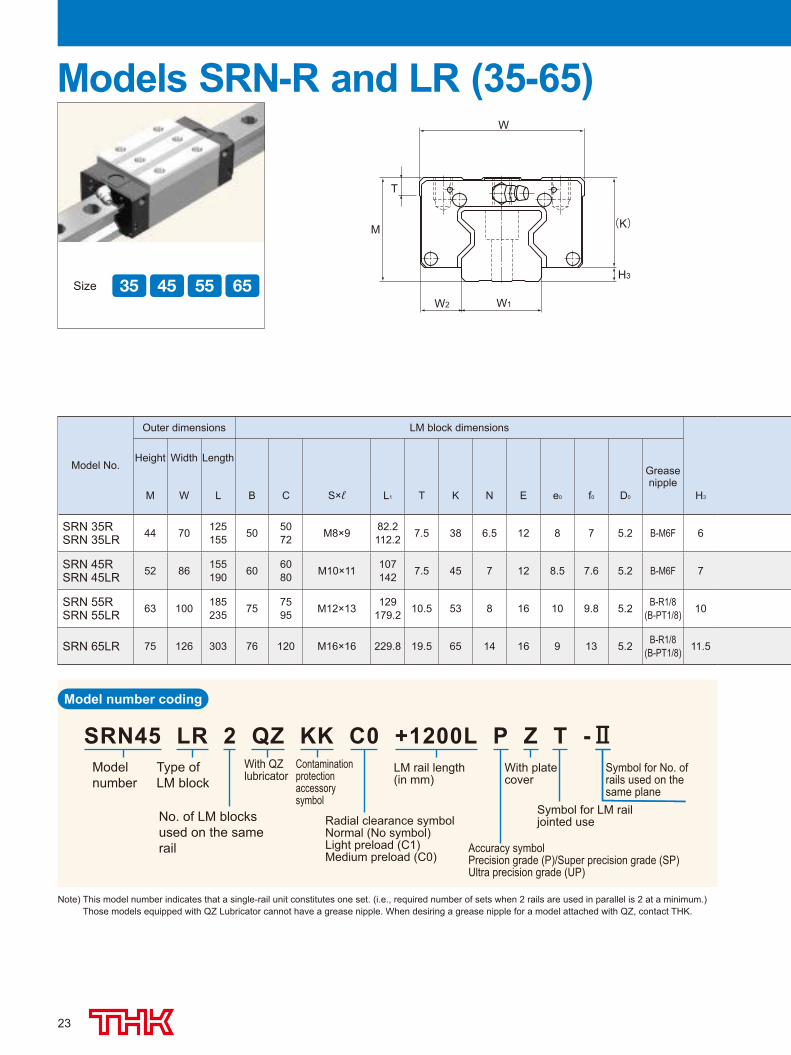
Models SRN-R and LR (35-65)
Model No.
Outer dimensions LM block dimensions
Height Width LengthGrease nipple
M W L B C S×ℓ L1 T K N E e0 f0 D0 H3
SRN 35RSRN 35LR 44 70 125
155 50 5072 M8×9 82.2
112.2 7.5 38 6.5 12 8 7 5.2 B-M6F 6
SRN 45RSRN 45LR 52 86 155
190 60 6080 M10×11 107
142 7.5 45 7 12 8.5 7.6 5.2 B-M6F 7
SRN 55RSRN 55LR 63 100 185
235 75 7595 M12×13 129
179.2 10.5 53 8 16 10 9.8 5.2 B-R1/8(B-PT1/8) 10
SRN 65LR 75 126 303 76 120 M16×16 229.8 19.5 65 14 16 9 13 5.2 B-R1/8(B-PT1/8) 11.5
Size
15 20 25 30
35 45 55 65
85 100
Note) This model number indicates that a single-rail unit constitutes one set. (i.e., required number of sets when 2 rails are used in parallel is 2 at a minimum.) Those models equipped with QZ Lubricator cannot have a grease nipple. When desiring a grease nipple for a model attached with QZ, contact THK.
508-0540_P13-24.indd 23 2015/09/11 11:45:49
24
φ d2
**4-φ D0
φ d1
e0
f0
L1 L
B
C
F
h N
M1
(E)
6-S×ℓ
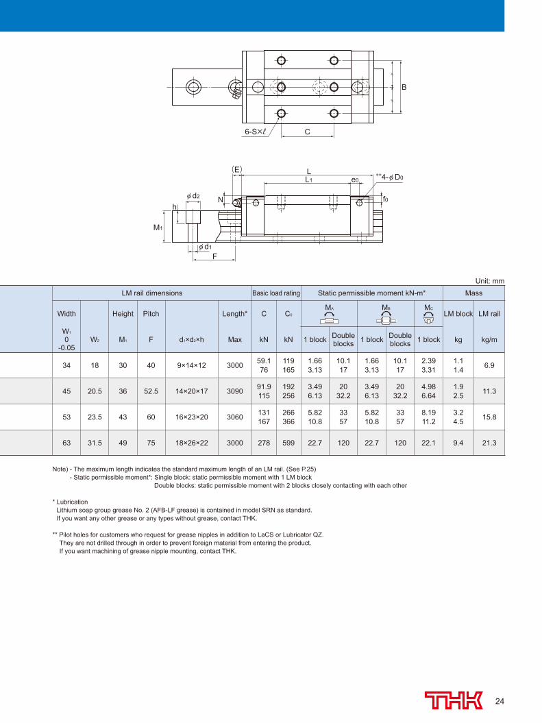
LM rail dimensions Basic load rating Static permissible moment kN-m* Mass
Width Height Pitch Length* C C0
MA MB MC
LM block LM rail
W1
0-0.05
W2 M1 F d1×d2×h Max kN kN 1 block Double blocks 1 block Double
blocks 1 block kg kg/m
34 18 30 40 9×14×12 3000 59.176
119165
1.663.13
10.117
1.663.13
10.117
2.393.31
1.11.4 6.9
45 20.5 36 52.5 14×20×17 3090 91.9115
192256
3.496.13
2032.2
3.496.13
2032.2
4.986.64
1.92.5 11.3
53 23.5 43 60 16×23×20 3060 131167
266366
5.8210.8
3357
5.8210.8
3357
8.1911.2
3.24.5 15.8
63 31.5 49 75 18×26×22 3000 278 599 22.7 120 22.7 120 22.1 9.4 21.3
Unit: mm
Note) - The maximum length indicates the standard maximum length of an LM rail. (See P.25) - Static permissible moment*: Single block: static permissible moment with 1 LM block Double blocks: static permissible moment with 2 blocks closely contacting with each other
* Lubrication Lithium soap group grease No. 2 (AFB-LF grease) is contained in model SRN as standard. If you want any other grease or any types without grease, contact THK.
** Pilot holes for customers who request for grease nipples in addition to LaCS or Lubricator QZ. They are not drilled through in order to prevent foreign material from entering the product. If you want machining of grease nipple mounting, contact THK.
508-0540_P13-24.indd 24 2015/09/11 11:45:50
25
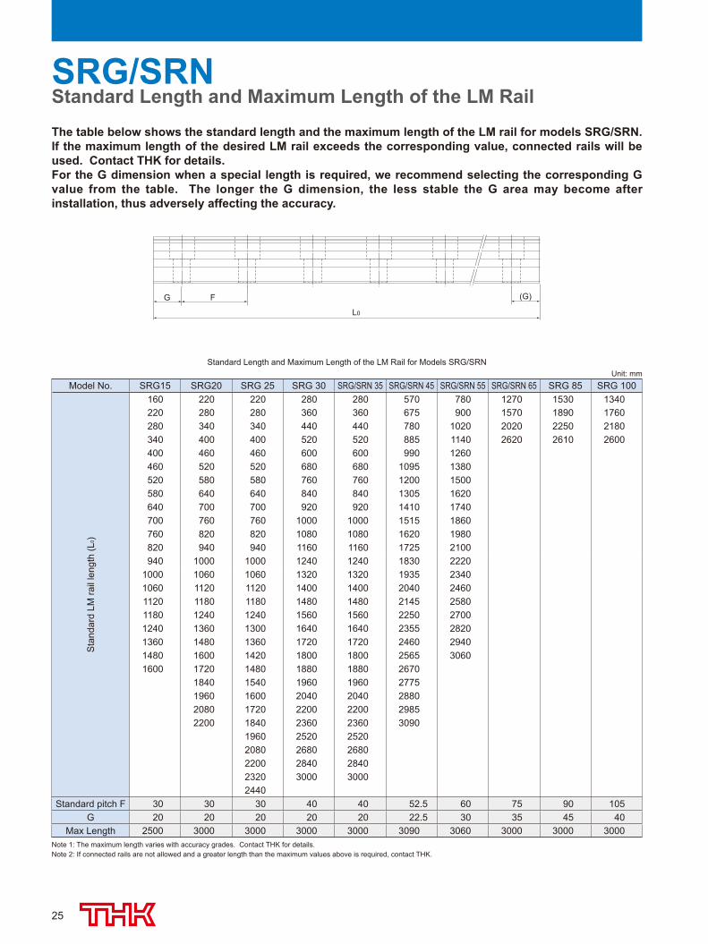
The table below shows the standard length and the maximum length of the LM rail for models SRG/SRN. If the maximum length of the desired LM rail exceeds the corresponding value, connected rails will be used. Contact THK for details.For the G dimension when a special length is required, we recommend selecting the corresponding G value from the table. The longer the G dimension, the less stable the G area may become after installation, thus adversely affecting the accuracy.
G F
L0
(G)
SRG/SRNStandard Length and Maximum Length of the LM Rail
Note 1: The maximum length varies with accuracy grades. Contact THK for details.Note 2: If connected rails are not allowed and a greater length than the maximum values above is required, contact THK.
Standard Length and Maximum Length of the LM Rail for Models SRG/SRNUnit: mm
Model No. SRG15 SRG20 SRG 25 SRG 30 SRG/SRN 35 SRG/SRN 45 SRG/SRN 55 SRG/SRN 65 SRG 85 SRG 100
Sta
ndar
d LM
rail
leng
th (L
0 )
160 220 220 280 280 570 780 1270 1530 1340220 280 280 360 360 675 900 1570 1890 1760280 340 340 440 440 780 1020 2020 2250 2180340 400 400 520 520 885 1140 2620 2610 2600400 460 460 600 600 990 1260460 520 520 680 680 1095 1380520 580 580 760 760 1200 1500580 640 640 840 840 1305 1620640 700 700 920 920 1410 1740700 760 760 1000 1000 1515 1860760 820 820 1080 1080 1620 1980820 940 940 1160 1160 1725 2100940 1000 1000 1240 1240 1830 2220
1000 1060 1060 1320 1320 1935 23401060 1120 1120 1400 1400 2040 24601120 1180 1180 1480 1480 2145 25801180 1240 1240 1560 1560 2250 27001240 1360 1300 1640 1640 2355 28201360 1480 1360 1720 1720 2460 29401480 1600 1420 1800 1800 2565 30601600 1720 1480 1880 1880 2670
1840 1540 1960 1960 27751960 1600 2040 2040 28802080 1720 2200 2200 29852200 1840 2360 2360 3090
1960 2520 25202080 2680 26802200 2840 28402320 3000 30002440
Standard pitch F 30 30 30 40 40 52.5 60 75 90 105G 20 20 20 20 20 22.5 30 35 45 40
Max Length 2500 3000 3000 3000 3000 3090 3060 3000 3000 3000
508-0540_P25-34.indd 25 2015/09/11 15:35:41
26
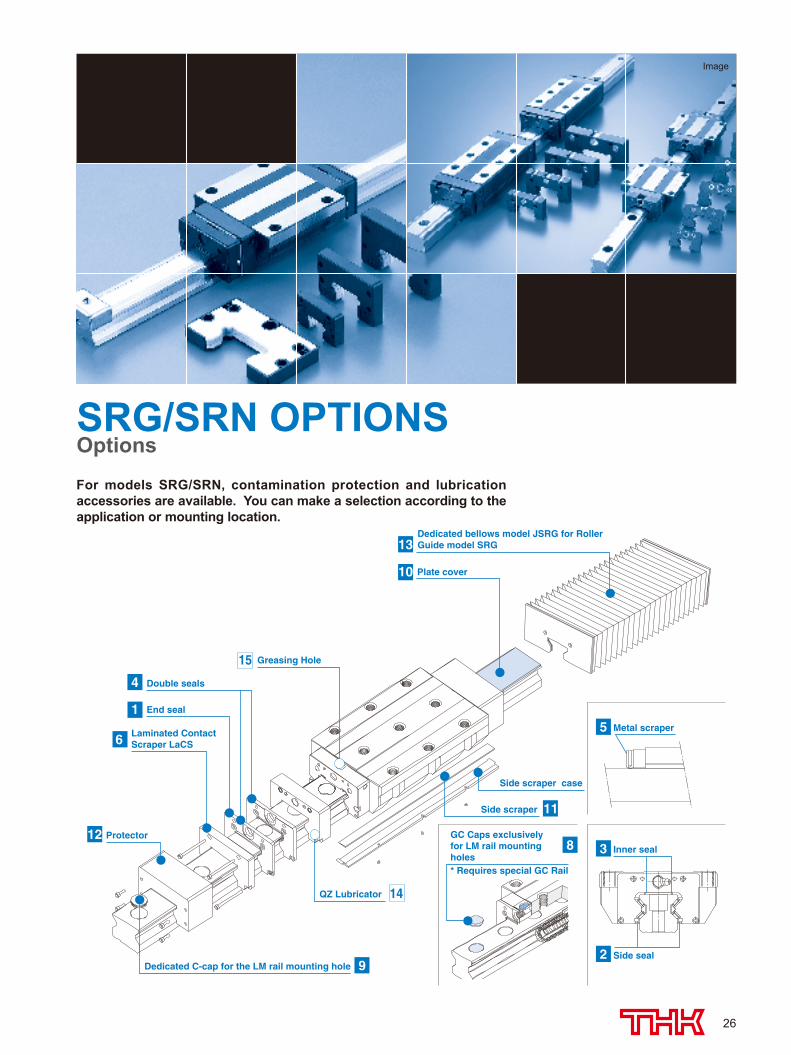
Dedicated bellows model JSRG for RollerGuide model SRG13
Laminated ContactScraper LaCS6
QZ Lubricator 14
End seal1
Double seals4
8 Inner seal3
Side seal2
GC Caps exclusively for LM rail mounting holes* Requires special GC Rail
Side scraper case
Dedicated C-cap for the LM rail mounting hole 9
Protector12
Greasing Hole 15
11Side scraper
Plate cover10
Metal scraper5
For models SRG/SRN, contamination protection and lubrication accessories are available. You can make a selection according to the application or mounting location.
Image
SRG/SRN OPTIONSOptions
508-0540_P25-34.indd 26 2015/09/11 15:35:41
27
Inner seal
End seal
Side seal
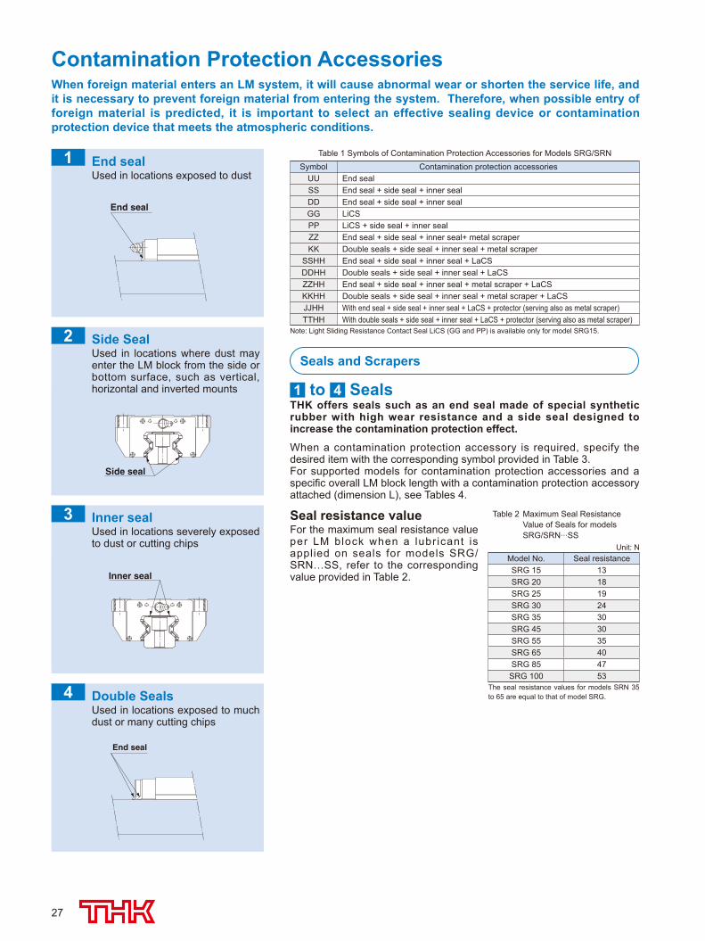
When foreign material enters an LM system, it will cause abnormal wear or shorten the service life, and it is necessary to prevent foreign material from entering the system. Therefore, when possible entry of foreign material is predicted, it is important to select an effective sealing device or contamination protection device that meets the atmospheric conditions.
Contamination Protection Accessories
Inner sealUsed in locations severely exposed to dust or cutting chips
End sealUsed in locations exposed to dust
1
2
3
Seals and Scrapers
1 to 4 SealsTHK offers seals such as an end seal made of special synthetic rubber with high wear resistance and a side seal designed to increase the contamination protection effect.
When a contamination protection accessory is required, specify the desired item with the corresponding symbol provided in Table 3.For supported models for contamination protection accessories and a specific overall LM block length with a contamination protection accessory attached (dimension L), see Tables 4.
Table 2 Maximum Seal Resistance Value of Seals for models SRG/SRN...SS
Seal resistance valueFor the maximum seal resistance value per LM block when a lubr icant is applied on seals for models SRG/SRN…SS, refer to the corresponding value provided in Table 2.
The seal resistance values for models SRN 35 to 65 are equal to that of model SRG.
Side SealUsed in locations where dust may enter the LM block from the side or bottom surface, such as vertical, horizontal and inverted mounts
Double SealsUsed in locations exposed to much dust or many cutting chips
End seal
Note: Light Sliding Resistance Contact Seal LiCS (GG and PP) is available only for model SRG15.
Unit: NModel No. Seal resistanceSRG 15 13SRG 20 18SRG 25 19SRG 30 24SRG 35 30SRG 45 30SRG 55 35SRG 65 40SRG 85 47SRG 100 53
Table 1 Symbols of Contamination Protection Accessories for Models SRG/SRNSymbol Contamination protection accessories
UU End sealSS End seal + side seal + inner sealDD End seal + side seal + inner sealGG LiCS PP LiCS + side seal + inner sealZZ End seal + side seal + inner seal+ metal scraperKK Double seals + side seal + inner seal + metal scraper
SSHH End seal + side seal + inner seal + LaCSDDHH Double seals + side seal + inner seal + LaCSZZHH End seal + side seal + inner seal + metal scraper + LaCSKKHH Double seals + side seal + inner seal + metal scraper + LaCSJJHH With end seal + side seal + inner seal + LaCS + protector (serving also as metal scraper) TTHH With double seals + side seal + inner seal + LaCS + protector (serving also as metal scraper)
4
508-0540_P25-34.indd 27 2015/09/11 15:35:41
28
OPTIONSOptions
Table 3 Maximum resistance for LaCS
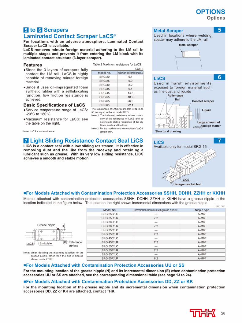
5 to 6 ScrapersLaminated Contact Scraper LaCS®
For locations with an adverse atmosphere, Laminated Contact Scraper LaCS is available.LaCS removes minute foreign material adhering to the LM rail in multiple stages and prevents it from entering the LM block with its laminated contact structure (3-layer scraper).
Features● Since the 3 layers of scrapers fully
contact the LM rail, LaCS is highly capable of removing minute foreign material.
● Since it uses oil-impregnated foam synthetic rubber with a selflubricating function, low friction resistance is achieved.
Basic Specifications of LaCS● Service temperature range of LaCS:
-20°C to +80°C● Maximum resistance for LaCS: see
the table on the right.
7 Light Sliding Resistance Contact Seal LiCSLiCS is a contact seal with a low sliding resistance. It is effective in removing dust and the like from the raceway and retaining a lubricant such as grease. With its very low sliding resistance, LiCS achieves a smooth and stable motion.
Metal ScraperUsed in locations where welding spatter may adhere to the LM rail
Metal scraper
■ For Models Attached with Contamination Protection Accessories SSHH, DDHH, ZZHH or KKHHModels attached with contamination protection accessories SSHH, DDHH, ZZHH or KKHH have a grease nipple in the location indicated in the figure below. The table on the right shows incremental dimensions with the grease nipple.
Unit: NModel No. Maximum resistance for LaCSSRG 20 6.1SRG 25 6.9SRG 30 8.2SRG 35 9.1SRG 45 14.3SRG 55 18.2SRG 65 26.0SRN 65 22.1
The resistances of LaCS for models SRN 35 to 55 are equal to that of model SRG.Note 1: The indicated resistance values consist
only of the resistance of LaCS and do not include sliding resistance of the LM block, seals and the likes.
Note 2: For the maximum service velocity of LaCS, contact THK.Note: LaCS is not sold alone.
5
Unit: mmModel No. Incremental dimension with grease nipple H Nipple type
SRG 25C/LC — A-M6FSRG 25R/LR 7.2 A-M6FSRG 30C/LC — A-M6FSRG 30R/LR 7.2 A-M6FSRG 35C/LC — A-M6FSRG 35R/LR 7.2 A-M6FSRG 45C/LC — A-M6FSRG 45R/LR 7.2 A-M6FSRG 55C/LC — A-M6FSRG 55R/LR 7.2 A-M6FSRG 65C/LC — A-M6FSRG 65R/LR 6.2 A-M6F
Grease nipple H
LaCS End plate K : Reference surface
Note: When desiring the mounting location for the grease nipple other than the one indicated above, contact THK.
■ For Models Attached with Contamination Protection Accessories UU or SS For the mounting location of the grease nipple (N) and its incremental dimension (E) when contamination protection accessories UU or SS are attached, see the corresponding dimensional table (see page 13 to 24).
■ For Models Attached with Contamination Protection Accessories DD, ZZ or KKFor the mounting location of the grease nipple and its incremental dimension when contamination protection accessories DD, ZZ or KK are attached, contact THK.
Liquid
Structural drawing
Large amount of foreign matter
Contact scraperBallRoller cage
LiCS
Hexagon socket bolt
LaCSUsed in harsh env i ronments exposed to foreign material such as fine dust and liquids
LiCSAvailable only for model SRG 15
6
7
508-0540_P25-34.indd 28 2015/09/11 15:35:41
29
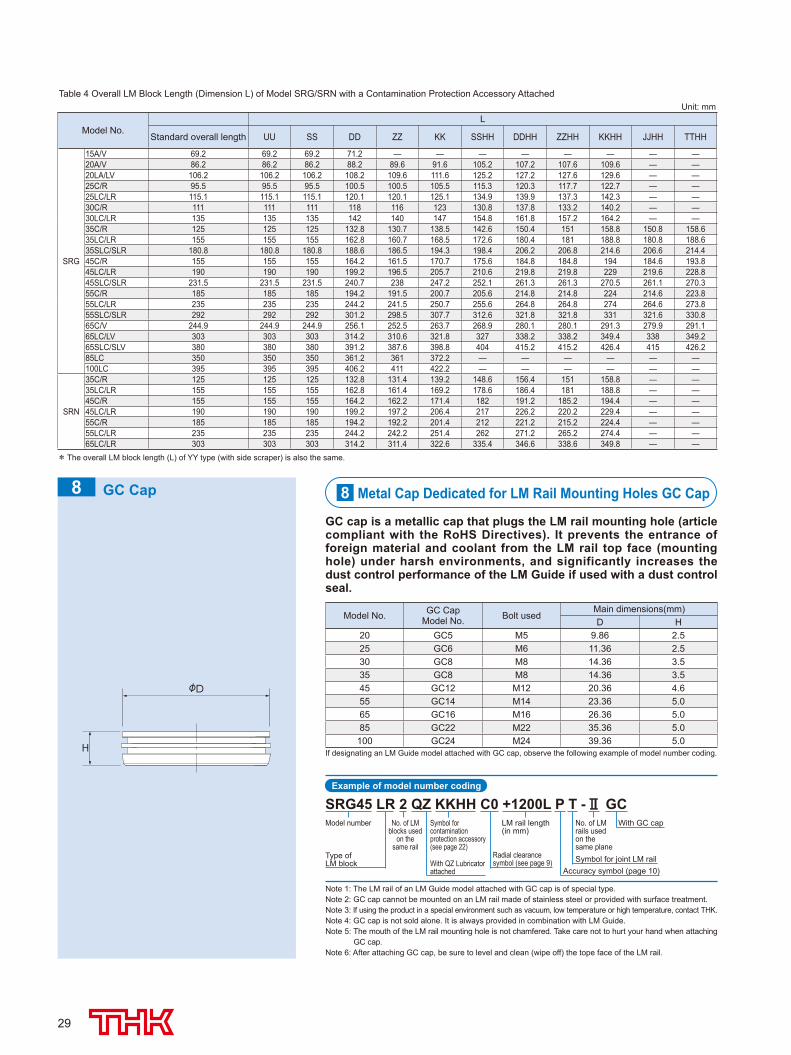
Note 1: The LM rail of an LM Guide model attached with GC cap is of special type.Note 2: GC cap cannot be mounted on an LM rail made of stainless steel or provided with surface treatment.Note 3: If using the product in a special environment such as vacuum, low temperature or high temperature, contact THK.Note 4: GC cap is not sold alone. It is always provided in combination with LM Guide.Note 5: The mouth of the LM rail mounting hole is not chamfered. Take care not to hurt your hand when attaching
GC cap.Note 6: After attaching GC cap, be sure to level and clean (wipe off) the tope face of the LM rail.
If designating an LM Guide model attached with GC cap, observe the following example of model number coding.
Example of model number coding
SRG45 LR 2 QZ KKHH C0 +1200L P T - GCModel number No. of LM
blocks usedon the
same railType of LM block With QZ Lubricator
attached
Symbol for contamination protection accessory (see page 22)
LM rail length (in mm)
No. of LM rails used on the same planeSymbol for joint LM rail
With GC cap
Accuracy symbol (page 10)
Radial clearance symbol (see page 9)
Table 4 Overall LM Block Length (Dimension L) of Model SRG/SRN with a Contamination Protection Accessory Attached
8 Metal Cap Dedicated for LM Rail Mounting Holes GC Cap
GC cap is a metallic cap that plugs the LM rail mounting hole (article compliant with the RoHS Directives). It prevents the entrance of foreign material and coolant from the LM rail top face (mounting hole) under harsh environments, and significantly increases the dust control performance of the LM Guide if used with a dust control seal.
Model No. GC CapModel No. Bolt used
Main dimensions(mm)D H
20 GC5 M5 9.86 2.525 GC6 M6 11.36 2.530 GC8 M8 14.36 3.535 GC8 M8 14.36 3.545 GC12 M12 20.36 4.655 GC14 M14 23.36 5.065 GC16 M16 26.36 5.085 GC22 M22 35.36 5.0100 GC24 M24 39.36 5.0
Unit: mm
Model No.L
Standard overall length UU SS DD ZZ KK SSHH DDHH ZZHH KKHH JJHH TTHH
SRG
15A/V 69.2 69.2 69.2 71.2 — — — — — — — —20A/V 86.2 86.2 86.2 88.2 89.6 91.6 105.2 107.2 107.6 109.6 — —20LA/LV 106.2 106.2 106.2 108.2 109.6 111.6 125.2 127.2 127.6 129.6 — —25C/R 95.5 95.5 95.5 100.5 100.5 105.5 115.3 120.3 117.7 122.7 — —25LC/LR 115.1 115.1 115.1 120.1 120.1 125.1 134.9 139.9 137.3 142.3 — —30C/R 111 111 111 118 116 123 130.8 137.8 133.2 140.2 — —30LC/LR 135 135 135 142 140 147 154.8 161.8 157.2 164.2 — —35C/R 125 125 125 132.8 130.7 138.5 142.6 150.4 151 158.8 150.8 158.635LC/LR 155 155 155 162.8 160.7 168.5 172.6 180.4 181 188.8 180.8 188.635SLC/SLR 180.8 180.8 180.8 188.6 186.5 194.3 198.4 206.2 206.8 214.6 206.6 214.445C/R 155 155 155 164.2 161.5 170.7 175.6 184.8 184.8 194 184.6 193.845LC/LR 190 190 190 199.2 196.5 205.7 210.6 219.8 219.8 229 219.6 228.845SLC/SLR 231.5 231.5 231.5 240.7 238 247.2 252.1 261.3 261.3 270.5 261.1 270.355C/R 185 185 185 194.2 191.5 200.7 205.6 214.8 214.8 224 214.6 223.855LC/LR 235 235 235 244.2 241.5 250.7 255.6 264.8 264.8 274 264.6 273.855SLC/SLR 292 292 292 301.2 298.5 307.7 312.6 321.8 321.8 331 321.6 330.865C/V 244.9 244.9 244.9 256.1 252.5 263.7 268.9 280.1 280.1 291.3 279.9 291.165LC/LV 303 303 303 314.2 310.6 321.8 327 338.2 338.2 349.4 338 349.265SLC/SLV 380 380 380 391.2 387.6 398.8 404 415.2 415.2 426.4 415 426.285LC 350 350 350 361.2 361 372.2 — — — — — —100LC 395 395 395 406.2 411 422.2 — — — — — —
SRN
35C/R 125 125 125 132.8 131.4 139.2 148.6 156.4 151 158.8 — —35LC/LR 155 155 155 162.8 161.4 169.2 178.6 186.4 181 188.8 — —45C/R 155 155 155 164.2 162.2 171.4 182 191.2 185.2 194.4 — —45LC/LR 190 190 190 199.2 197.2 206.4 217 226.2 220.2 229.4 — —55C/R 185 185 185 194.2 192.2 201.4 212 221.2 215.2 224.4 — —55LC/LR 235 235 235 244.2 242.2 251.4 262 271.2 265.2 274.4 — —65LC/LR 303 303 303 314.2 311.4 322.6 335.4 346.6 338.6 349.8 — —
* The overall LM block length (L) of YY type (with side scraper) is also the same.
GC Cap8
508-0540_P25-34.indd 29 2015/09/11 15:35:42
30
OPTIONSOptions
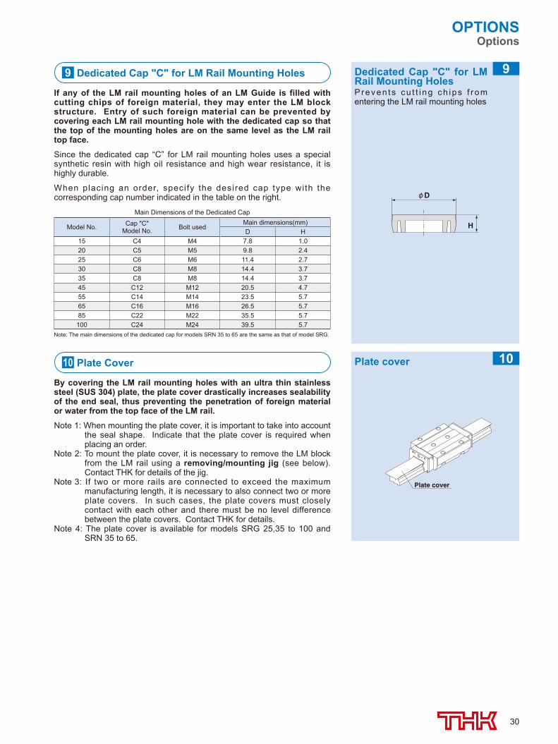
Main Dimensions of the Dedicated Cap
Note: The main dimensions of the dedicated cap for models SRN 35 to 65 are the same as that of model SRG.
Model No. Cap "C"Model No. Bolt used
Main dimensions(mm)D H
15 C4 M4 7.8 1.020 C5 M5 9.8 2.425 C6 M6 11.4 2.730 C8 M8 14.4 3.735 C8 M8 14.4 3.745 C12 M12 20.5 4.755 C14 M14 23.5 5.765 C16 M16 26.5 5.785 C22 M22 35.5 5.7100 C24 M24 39.5 5.7
9 Dedicated Cap "C" for LM Rail Mounting Holes
If any of the LM rail mounting holes of an LM Guide is filled with cutting chips of foreign material, they may enter the LM block structure. Entry of such foreign material can be prevented by covering each LM rail mounting hole with the dedicated cap so that the top of the mounting holes are on the same level as the LM rail top face.
Since the dedicated cap “C” for LM rail mounting holes uses a special synthetic resin with high oil resistance and high wear resistance, it is highly durable.
When placing an order, specify the desired cap type with the corresponding cap number indicated in the table on the right. D
H
Dedicated Cap "C" for LM Rail Mounting HolesPreven ts cu t t i ng ch ips f r om entering the LM rail mounting holes
9
10 Plate Cover
By covering the LM rail mounting holes with an ultra thin stainless steel (SUS 304) plate, the plate cover drastically increases sealability of the end seal, thus preventing the penetration of foreign material or water from the top face of the LM rail.
Note 1: When mounting the plate cover, it is important to take into account the seal shape. Indicate that the plate cover is required when placing an order.
Note 2: To mount the plate cover, it is necessary to remove the LM block from the LM rail using a removing/mounting jig (see below). Contact THK for details of the jig.
Note 3: If two or more rails are connected to exceed the maximum manufacturing length, it is necessary to also connect two or more plate covers. In such cases, the plate covers must closely contact with each other and there must be no level difference between the plate covers. Contact THK for details.
Note 4: The plate cover is available for models SRG 25,35 to 100 and SRN 35 to 65.
Plate cover
Plate cover 10
508-0540_P25-34.indd 30 2015/09/11 15:35:42
31
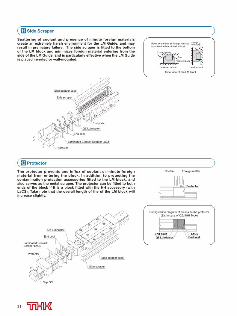
The protector prevents and influx of coolant or minute foreign material from entering the block, in addition to protecting the contamination protection accessories fitted to the LM block, and also serves as the metal scraper. The protector can be fitted to both ends of the block if it is a block fitted with the HH accessory (with LaCS). Take note that the overall length of the of the LM block will increase slightly.
11 Side Scraper
12 Protector
Spattering of coolant and presence of minute foreign materials create an extremely harsh environment for the LM Guide, and may result in premature failure. The side scraper is fitted to the bottom of the LM block and minimizes foreign material entering from the side of the LM Guide, and is particularly effective when the LM Guide is placed inverted or wall-mounted.
Side face of the LM block
Foreign material
Foreign material
Foreign material
Inverted mount Wall mount
Route of entrance by foreign material from the side face of the LM block
Protector
Foreign matterCoolant
End plateQZ Lubricator End seal
Configuration diagram of the inside the protector(Ex: in case of QZJJHH Type)
LaCS
Side scraper case
Side scraper
Protector
Laminated Contact Scraper LaCS
End seal
QZ Lubricator
End plate
Laminated Contact Scraper LaCS
Protector
QZ Lubricator
Side scraper
Side scraper case
End seal
Cap GC
508-0540_P25-34.indd 31 2015/09/11 15:35:42
32
OPTIONSOptions
Removing/mounting jig
Removing/mounting jig(material: ABS resin)
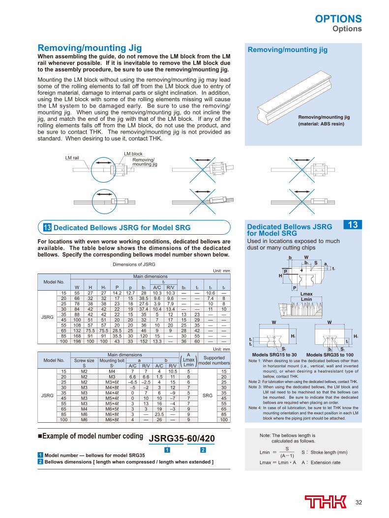
Removing/mounting JigWhen assembling the guide, do not remove the LM block from the LM rail whenever possible. If it is inevitable to remove the LM block due to the assembly procedure, be sure to use the removing/mounting jig.
Mounting the LM block without using the removing/mounting jig may lead some of the rolling elements to fall off from the LM block due to entry of foreign material, damage to internal parts or slight inclination. In addition, using the LM block with some of the rolling elements missing will cause the LM system to be damaged early. Be sure to use the removing/mounting jig. When using the removing/mounting jig, do not incline the jig, and match the end of the jig with that of the LM block. If any of the rolling elements falls off from the LM block, do not use the product, and be sure to contact THK. The removing/mounting jig is not provided as standard. When desiring to use it, contact THK.
Note 1: When desiring to use the dedicated bellows other than in horizontal mount (i.e., vertical, wall and inverted mount), or when desiring a heatresistant type of bellow, contact THK.
Note 2: For lubrication when using the dedicated bellows, contact THK.Note 3: When using the dedicated bellows, the LM block and
LM rail need to be machined so that the bellows can be mounted. Be sure to indicate that the dedicated bellows are required when placing an order.
Note 4: In case of oil lubrication, be sure to let THK know the mounting orientation and the exact position in each LM block where the piping joint should be attached.
bb1 SW
P
pH
at1
H1
W
S1b2
H1
t2t4
t3
W
S1
Models SRG15 to 30 Models SRG35 to 100
LminLmax
13 Dedicated Bellows JSRG for Model SRG
For locations with even worse working conditions, dedicated bellows are available. The table below shows the dimensions of the dedicated bellows. Specify the corresponding bellows model number shown below.
Dedicated Bellows JSRG for Model SRGUsed in locations exposed to much dust or many cutting chips
13
Unit: mm
Model No.Main dimensions
t1
W H H1 P p b1 A/C R/V b2 t2 t3 t4
JSRG
15 55 27 27 14.2 12.7 28 10.3 10.3 — — 10.6 —20 66 32 32 17 15 38.5 9.6 9.6 — — 7.4 825 78 38 38 23 18 27.6 3.9 7.9 — — 10 830 84 42 42 22 19 37.4 10.4 13.4 — — 11 1035 88 42 42 22 15 35 5 12 13 23 — —45 100 51 51 20 20 32 7 17 15 29 — —55 108 57 57 20 20 36 10 20 25 35 — —65 132 75.5 75.5 28.5 25 46 9 9 28 42 — —85 168 91 91 35.5 30 120 15 — 30 55 — —100 198 100 100 43 33 152 13.3 — 36 60 — —
Unit: mm
Model No.Main dimensions A
Lmax Lmin
Supported model numbersScrew size
SMounting bolt
S1
a bA/C R/V A/C R/V
JSRG
15 M2 M4 7 7 4 10.5 5
SRG
1520 M2 M3 6.6 6.6 1.5 11 6 2025 M2 M3×6ℓ –6.5 –2.5 4 15 6 2530 M3 M4×8ℓ –5 –2 3 12 7 3035 M3 M4×4ℓ 0 7 6 –9 5 3545 M3 M5×4ℓ 0 10 10 –7 7 4555 M3 M5×4ℓ 3 13 16 –4 7 5565 M4 M6×5ℓ 3 3 19 –3 9 6585 M6 M6×8ℓ 3 — 23.5 — 9 85100 M6 M6×8ℓ 4 — 26 — 9 100
Dimensions of JSRG
Lmin = S: Stroke length (mm)
Lmax = Lmin・A A: Extension rate
S(A-1)
Note: The bellows length is calculated as follows.
■Example of model number coding JSRG35-60/4201 Model number --- bellows for model SRG352 Bellows dimensions [ length when compressed / length when extended ]
1 2
Removing/mounting jig
LM blockLM rail
508-0540_P25-34.indd 32 2015/09/11 15:35:42
33
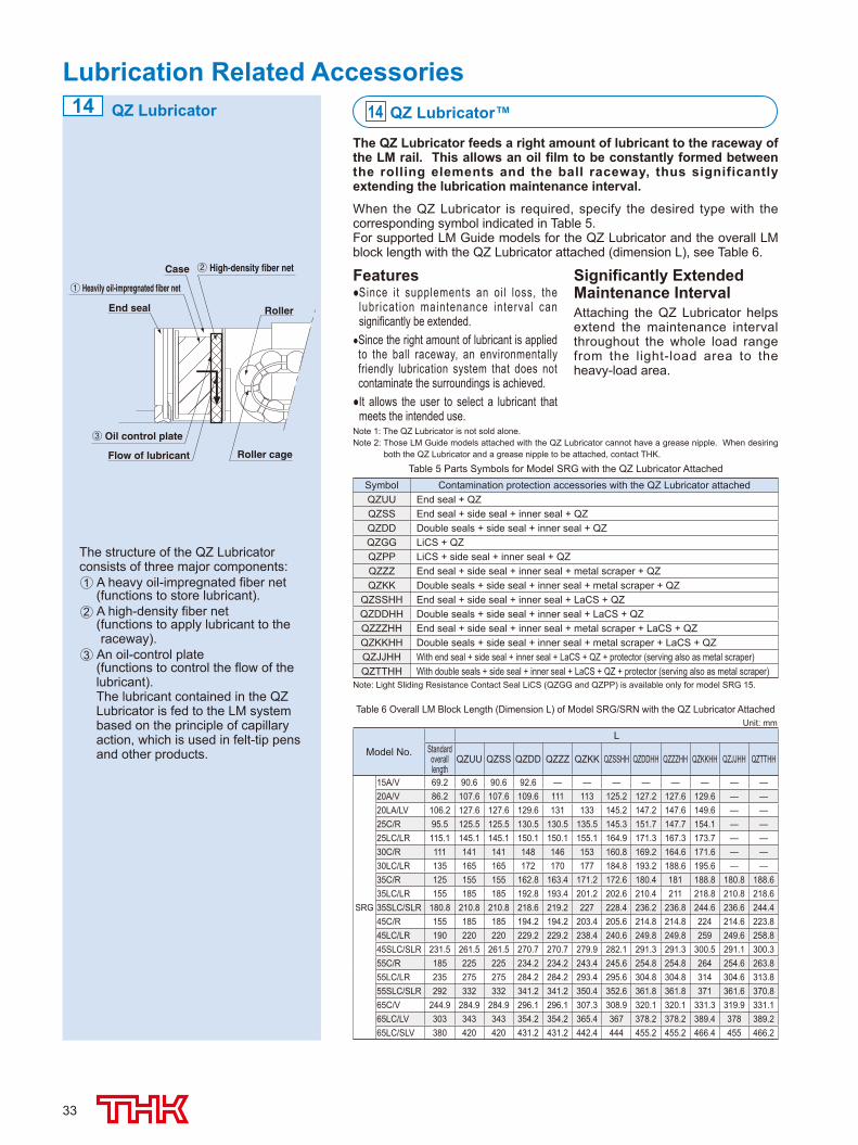
QZ Lubricator
End seal
Flow of lubricant
Oil control plate
Roller cage
Roller
Case High-density fiber net
1 Heavily oil-impregnated fiber net
2
3
Features● Since it supplements an oi l loss, the
lubr icat ion maintenance interval can significantly be extended.
● Since the right amount of lubricant is applied to the ball raceway, an environmentally friendly lubrication system that does not contaminate the surroundings is achieved.● It allows the user to select a lubricant that
meets the intended use.
Significantly Extended Maintenance IntervalAttaching the QZ Lubricator helps extend the maintenance interval throughout the whole load range from the light-load area to the heavy-load area.
Note 1: The QZ Lubricator is not sold alone.Note 2: Those LM Guide models attached with the QZ Lubricator cannot have a grease nipple. When desiring
both the QZ Lubricator and a grease nipple to be attached, contact THK.
Table 6 Overall LM Block Length (Dimension L) of Model SRG/SRN with the QZ Lubricator Attached
The structure of the QZ Lubricator consists of three major components:1 A heavy oil-impregnated fiber net
(functions to store lubricant).2 A high-density fiber net
( functions to apply lubricant to the raceway).
3 An oil-control plate (functions to control the flow of the
lubricant). The lubricant contained in the QZ
Lubricator is fed to the LM system based on the principle of capillary action, which is used in felt-tip pens and other products.
14 QZ Lubricator™
The QZ Lubricator feeds a right amount of lubricant to the raceway of the LM rail. This allows an oil film to be constantly formed between the rolling elements and the ball raceway, thus significantly extending the lubrication maintenance interval.
When the QZ Lubricator is required, specify the desired type with the corresponding symbol indicated in Table 5.For supported LM Guide models for the QZ Lubricator and the overall LM block length with the QZ Lubricator attached (dimension L), see Table 6.
Lubrication Related Accessories
Note: Light Sliding Resistance Contact Seal LiCS (QZGG and QZPP) is available only for model SRG 15.
Table 5 Parts Symbols for Model SRG with the QZ Lubricator AttachedSymbol Contamination protection accessories with the QZ Lubricator attachedQZUU End seal + QZQZSS End seal + side seal + inner seal + QZQZDD Double seals + side seal + inner seal + QZQZGG LiCS + QZQZPP LiCS + side seal + inner seal + QZQZZZ End seal + side seal + inner seal + metal scraper + QZQZKK Double seals + side seal + inner seal + metal scraper + QZ
QZSSHH End seal + side seal + inner seal + LaCS + QZQZDDHH Double seals + side seal + inner seal + LaCS + QZQZZZHH End seal + side seal + inner seal + metal scraper + LaCS + QZQZKKHH Double seals + side seal + inner seal + metal scraper + LaCS + QZQZJJHH With end seal + side seal + inner seal + LaCS + QZ + protector (serving also as metal scraper)QZTTHH With double seals + side seal + inner seal + LaCS + QZ + protector (serving also as metal scraper)
14
Unit: mm
Model No.L
Standard overall length
QZUU QZSS QZDD QZZZ QZKK QZSSHH QZDDHH QZZZHH QZKKHH QZJJHH QZTTHH
SRG
15A/V 69.2 90.6 90.6 92.6 — — — — — — — —20A/V 86.2 107.6 107.6 109.6 111 113 125.2 127.2 127.6 129.6 — —20LA/LV 106.2 127.6 127.6 129.6 131 133 145.2 147.2 147.6 149.6 — —25C/R 95.5 125.5 125.5 130.5 130.5 135.5 145.3 151.7 147.7 154.1 — —25LC/LR 115.1 145.1 145.1 150.1 150.1 155.1 164.9 171.3 167.3 173.7 — —30C/R 111 141 141 148 146 153 160.8 169.2 164.6 171.6 — —30LC/LR 135 165 165 172 170 177 184.8 193.2 188.6 195.6 — —35C/R 125 155 155 162.8 163.4 171.2 172.6 180.4 181 188.8 180.8 188.635LC/LR 155 185 185 192.8 193.4 201.2 202.6 210.4 211 218.8 210.8 218.635SLC/SLR 180.8 210.8 210.8 218.6 219.2 227 228.4 236.2 236.8 244.6 236.6 244.445C/R 155 185 185 194.2 194.2 203.4 205.6 214.8 214.8 224 214.6 223.845LC/LR 190 220 220 229.2 229.2 238.4 240.6 249.8 249.8 259 249.6 258.845SLC/SLR 231.5 261.5 261.5 270.7 270.7 279.9 282.1 291.3 291.3 300.5 291.1 300.355C/R 185 225 225 234.2 234.2 243.4 245.6 254.8 254.8 264 254.6 263.855LC/LR 235 275 275 284.2 284.2 293.4 295.6 304.8 304.8 314 304.6 313.855SLC/SLR 292 332 332 341.2 341.2 350.4 352.6 361.8 361.8 371 361.6 370.865C/V 244.9 284.9 284.9 296.1 296.1 307.3 308.9 320.1 320.1 331.3 319.9 331.165LC/LV 303 343 343 354.2 354.2 365.4 367 378.2 378.2 389.4 378 389.265LC/SLV 380 420 420 431.2 431.2 442.4 444 455.2 455.2 466.4 455 466.2
508-0540_P25-34.indd 33 2015/09/11 15:35:42
34
OPTIONSOptions
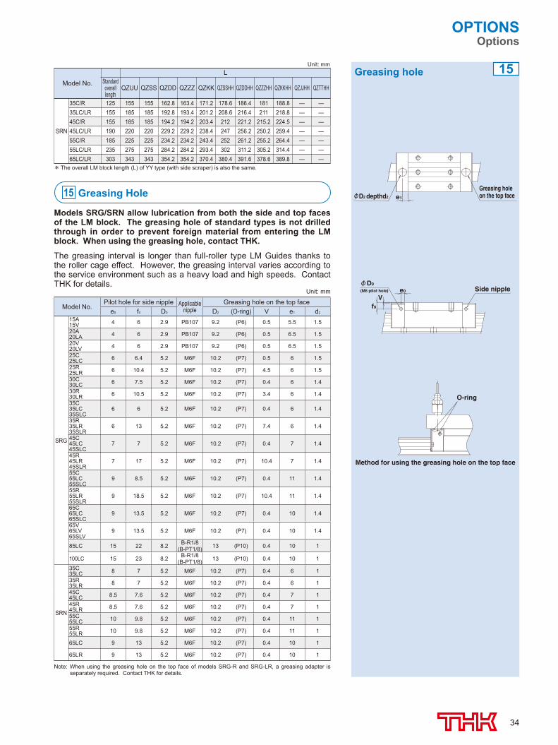
15 Greasing Hole
Models SRG/SRN allow lubrication from both the side and top faces of the LM block. The greasing hole of standard types is not drilled through in order to prevent foreign material from entering the LM block. When using the greasing hole, contact THK.
The greasing interval is longer than full-roller type LM Guides thanks to the roller cage effect. However, the greasing interval varies according to the service environment such as a heavy load and high speeds. Contact THK for details.
e1
Greasing holeon the top faceD2 depthd2
Vf0
e0
D0Side nipple(M6 pilot hole)
Method for using the greasing hole on the top face
O-ring
Greasing holeUnit: mm
Model No.L
Standard overall length
QZUU QZSS QZDD QZZZ QZKK QZSSHH QZDDHH QZZZHH QZKKHH QZJJHH QZTTHH
SRN
35C/R 125 155 155 162.8 163.4 171.2 178.6 186.4 181 188.8 — —35LC/LR 155 185 185 192.8 193.4 201.2 208.6 216.4 211 218.8 — —45C/R 155 185 185 194.2 194.2 203.4 212 221.2 215.2 224.5 — —45LC/LR 190 220 220 229.2 229.2 238.4 247 256.2 250.2 259.4 — —55C/R 185 225 225 234.2 234.2 243.4 252 261.2 255.2 264.4 — —55LC/LR 235 275 275 284.2 284.2 293.4 302 311.2 305.2 314.4 — —65LC/LR 303 343 343 354.2 354.2 370.4 380.4 391.6 378.6 389.8 — —
* The overall LM block length (L) of YY type (with side scraper) is also the same.
15
Note: When using the greasing hole on the top face of models SRG-R and SRG-LR, a greasing adapter is separately required. Contact THK for details.
Unit: mm
Model No.Pilot hole for side nipple Applicable
nippleGreasing hole on the top face
e0 f0 D0 D2 (O-ring) V e1 d2
SRG
15A15V 4 6 2.9 PB107 9.2 (P6) 0.5 5.5 1.520A20LA 4 6 2.9 PB107 9.2 (P6) 0.5 6.5 1.520V20LV 4 6 2.9 PB107 9.2 (P6) 0.5 6.5 1.525C25LC 6 6.4 5.2 M6F 10.2 (P7) 0.5 6 1.525R25LR 6 10.4 5.2 M6F 10.2 (P7) 4.5 6 1.530C30LC 6 7.5 5.2 M6F 10.2 (P7) 0.4 6 1.430R30LR 6 10.5 5.2 M6F 10.2 (P7) 3.4 6 1.435C35LC35SLC
6 6 5.2 M6F 10.2 (P7) 0.4 6 1.4
35R35LR35SLR
6 13 5.2 M6F 10.2 (P7) 7.4 6 1.4
45C45LC45SLC
7 7 5.2 M6F 10.2 (P7) 0.4 7 1.4
45R45LR45SLR
7 17 5.2 M6F 10.2 (P7) 10.4 7 1.4
55C55LC55SLC
9 8.5 5.2 M6F 10.2 (P7) 0.4 11 1.4
55R55LR55SLR
9 18.5 5.2 M6F 10.2 (P7) 10.4 11 1.4
65C65LC65SLC
9 13.5 5.2 M6F 10.2 (P7) 0.4 10 1.4
65V65LV65SLV
9 13.5 5.2 M6F 10.2 (P7) 0.4 10 1.4
85LC 15 22 8.2 B-R1/8(B-PT1/8) 13 (P10) 0.4 10 1
100LC 15 23 8.2 B-R1/8(B-PT1/8) 13 (P10) 0.4 10 1
SRN
35C35LC 8 7 5.2 M6F 10.2 (P7) 0.4 6 135R35LR 8 7 5.2 M6F 10.2 (P7) 0.4 6 145C45LC 8.5 7.6 5.2 M6F 10.2 (P7) 0.4 7 145R45LR 8.5 7.6 5.2 M6F 10.2 (P7) 0.4 7 155C55LC 10 9.8 5.2 M6F 10.2 (P7) 0.4 11 155R55LR 10 9.8 5.2 M6F 10.2 (P7) 0.4 11 1
65LC 9 13 5.2 M6F 10.2 (P7) 0.4 10 1
65LR 9 13 5.2 M6F 10.2 (P7) 0.4 10 1
508-0540_P25-34.indd 34 2015/09/11 15:35:43
Caged Roller LM Guide SRG/SRN
• “LM GUIDE,” and “ RollerRoller ” are registered trademarks of THK CO., LTD.
• The photo may differ slightly in appearance from the actual product.• The appearance and specifications of the product are subject to change without notice. Contact THK before placing an order.• Although great care has been taken in the production of this catalog, THK will not take any responsibility for damage resulting from typographical errors or omissions.• For the export of our products or technologies and for the sale for exports, THK in principle complies with the foreign exchange law and the Foreign Exchange
and Foreign Trade Control Law as well as other relevant laws. For export of THK products as single items, contact THK in advance. All rights reserved
DÜSSELDORF OFFICEPhone:+49-2102-7425-0 Fax:+49-2102-7425-299
EUROPETHK GmbH
EUROPEAN HEADQUARTERSPhone:+49-2102-7425-555 Fax:+49-2102-7425-556
Global site : http://www.thk.com/
©THK CO., LTD. 201509000 EE25
TURKEY OFFICEPhone:+90-216-362-4050 Fax:+90-216-569-7150
MOSCOW OFFICEPhone:+7-495-649-80-47 Fax:+7-495-649-80-44
STUTTGART OFFICEPhone:+49-7141-4988-500 Fax:+49-7141-4988-888U.K. OFFICEPhone:+44-1384-47-1550 Fax:+44-1384-47-1551ITALY OFFICEPhone:+39-02-9901-1801 Fax:+39-02-9901-1881SWEDEN OFFICEPhone:+46-8-445-7630 Fax:+46-8-445-7639 AUSTRIA OFFICEPhone:+43-7229-51400 Fax:+43-7229-51400-79SPAIN OFFICEPhone:+34-93-652-5740 Fax:+34-93-652-5746
PRAGUE OFFICEPhone:+420-2-41025-100 Fax:+420-2-41025-199
THK France S.A.S.
EINDHOVEN OFFICETHK Europe B.V.
Phone:+31-040-290-9500 Fax:+31-040-290-9599
PARIS OFFICEPhone:+33-1-7425-3800 Fax:+33-1-7425-3799
BEIJING OFFICEPhone:+86-10-8441-7277 Fax:+86-10-6590-3557CHENGDU OFFICEPhone:+86-28-8526-8025 Fax:+86-28-8525-6357
NORTH EAST OFFICE Phone:+1-631-244-1565 Fax:+1-631-244-1565ATLANTA OFFICEPhone:+1-770-840-7990 Fax:+1-770-840-7897LOS ANGELES OFFICEPhone:+1-949-955-3145 Fax:+1-949-955-3149SAN FRANCISCO OFFICEPhone:+1-925-455-8948 Fax:+1-925-455-8965DETROIT OFFICEPhone:+1-248-858-9330 Fax:+1-248-858-9455TORONTO OFFICEPhone:+1-905-820-7800 Fax:+1-905-820-7811
SOUTH AMERICATHK BRAZIL INDUSTRIA E COMERCIO LTDA.
Phone:+55-11-3767-0100 Fax:+55-11-3767-0101CHINATHK (CHINA) CO.,LTD.
SHANGHAI OFFICEPhone:+86-21-6219-3000 Fax:+86-21-6219-9890
HEADQUARTERSPhone:+86-411-8733-7111 Fax:+86-411-8733-7000
TAIWANTHK TAIWAN CO.,LTD.
TAIPEI HEAD OFFICEPhone:+886-2-2888-3818TAICHUNG OFFICEPhone:+886-4-2359-1505 TAINAN OFFICEPhone:+886-6-289-7668
KOREASEOUL REPRESENTATIVE OFFICE
Phone:+82-2-3468-4351SINGAPORETHK LM System Pte. Ltd.
Fax:+886-2-2888-3819
Fax:+886-4-2359-1506
THK India Pvt. Ltd. HEADQUARTERS & Bangalore BranchPhone:+91-80-2340-9934Pune BranchPhone:+91-20-4120-8742
Fax:+91-80-2340-9937
Chennai BranchPhone:+91-44-4042-3132Ahmedabad BranchPhone:+91-79-6134-4444
Fax:+886-6-289-7669
Fax:+82-2-3468-4353
Fax:+65-6884-5550
INDIA
Phone:+65-6884-5500THAILANDTHK RHYTHM(THAILAND) CO., LTD. LM System Division
Bangkok BranchPhone:+66-2751-3001 Fax:+66-2751-3003
Head Office 3-11-6 Nishigotanda, Shinagawa-ku, Tokyo 141-8503 JAPANInternational Sales Department Phone:+81-3-5434-0351 Fax:+81-3-5434-0353
THK America,Inc.HEADQUARTERSPhone:+1-847-310-1111 Fax:+1-847-310-1271CHICAGO OFFICEPhone:+1-847-310-1111 Fax:+1-847-310-1182
NORTH AMERICA
GUANGZHOU OFFICEPhone:+86-20-8523-8418 Fax:+86-20-3801-0456
THK (SHANGHAI) CO.,LTD.Phone:+86-21-6275-5280 Fax:+86-21-6219-9890
SHENZHEN OFFICEPhone:+86-755-2642-9587 Fax:+86-755-2642-9604XIAN OFFICEPhone:+86-29-8834-1712 Fax:+86-29-8834-1710
Technical Support Site The THK Technical Support Site lets you access product information and technical support online. You will also find a search feature for locating desired products and a calculation feature for calculating service life. 2D-CAD and 3D-CAD data are also downloadable.
Catalog Information
CAD Data
Technical Calculation
Technical Information
Product Information
FAQ
Search
508-0540_H4.indd h4 2015/09/11 11:44:05