calaveras county rules and regulations for · pdf file3 calaveras county onsite wastewater...
TRANSCRIPT

1
CALAVERAS COUNTY
RULES AND REGULATIONS
FOR
ONSITE WASTEWATER TREATMENT SYSTEMS
VOLUME I - DEVELOPMENT STANDARDS
RESOLUTION 92-259
AS AMENDED BY
RESOLUTION 93-45, 94-195, 10-147, 12-113, 1834 and 20170314r039.
March 14, 2017

2
TABLE OF CONTENTS
VOLUME I - DEVELOPMENT STANDARDS
Chapter 1 General 3
A. Purpose 3
B. Definitions 3
C. General Provision 12
Chapter 2 Requirements for Onsite Wastewater Treatment 14
Systems
A. General 14
B. Onsite Wastewater Treatment System Permit
Requirements 15
C. Site Evaluation 17
Chapter 3 Land Development/Creation of New Parcels 18
A. Land Development/Creation of New Parcels 18
Chapter 4 Alteration of Existing System 23
A. Permit Required 23
B. Modification Prohibited 23
C. System Repairs 23
D. Bedroom Additions 25
E. Abatement Required 25
Chapter 5 Areas of Special Consideration 26
A. Designation 26
B. Additional Requirements 26
C. State Jurisdiction 26
D. Rebuild Requirements 26
E. Graywater Systems 27

3
CALAVERAS COUNTY
ONSITE WASTEWATER TREATMENT DEPARTMENT
RULES AND REGULATIONS
FOR
ONSITE WASTEWATER TREATMENT SYSTEMS
VOLUME I - DEVELOPMENT STANDARDS
CHAPTER 1 - GENERAL
A. Purpose
These rules and regulations are adopted pursuant to the most recent ordinance addressing
wastewater disposal as adopted by the Calaveras County Board of Supervisors. Contained herein
are prescriptive standards for the field evaluation, design and construction of onsite wastewater
treatment systems. The purpose of the rules and regulations is for preventing conditions of
pollution and nuisance, to preserve the quality of surface and groundwater and to protect the
public health and safety of the citizens of Calaveras County. These regulations supersede all
previous regulations and written policies and adopts by reference any state mandated law and/or
regulation pertaining to design and installation of onsite wastewater treatment systems.
B. Definitions
1. "Absorption Facility" - means a system of perforated piping, alternative distribution units, or
other seepage systems used for receiving the flow from septic tanks or other treatment facilities
and designed to distribute effluent for oxidation and absorption by the soil within the zone of
aeration.
2. "Accessory Dwelling" – means either an attached or detached dwelling unit which provides
potential living facilities for one or more persons, and exceeds the permitted density for a parcel
by one dwelling unit. Caretakers quarters are included.
3. "Administrative Authority" – means a governmental agency that adopts or enforces
regulations and guidelines for the design, construction, or alteration of buildings and facilities.
For purposes of these regulations, the administrative authority is the Onsite Wastewater
Treatment Department.
4."Advanced Treatment System/Unit"- means an onsite wastewater treatment system (OWTS)
that does not conform to the parameters of a pressure dosed or gravity fed standard system.
Advanced Treatment System/Units reduce total dissolved solids (TDS), pathogens and total
nitrogen (TN) among other constituents. Advanced Treatment System/Units include, but are not

4
limited to, intermittent sand filters, textile-based packed bed filters (textile filters), mound
systems and aerobic treatment units.
Advanced Treatment as used in these regulations shall have the same meaning as
supplemental treatment.
5. "Agency Administrator" - means the Environmental Management Agency Administrator, or
any designated or authorized agent thereof. For purposes of these regulations, agency
administrator also includes the director of environmental health.
6. "Alteration" - means expansion and/or change in location of an existing Onsite Wastewater
Treatment System (OWTS) as defined in these regulations or any part thereof.
7. "Application Area" – means effective seepage area as defined in these regulations.
8. "Application Rate" – means the rate at which effluent is applied to an effective seepage area as
expressed in gallons per day per square foot (gpd/ sq. ft.)
9. "Bathroom "– means an area including a basin with one or more of the following: a water-
closet, a tub or a shower.
10. "Bedroom" - means a conditioned room used for sleeping and/or any room within a dwelling
which could be used as a bedroom or guest room as defined in these regulations.
Offices, studies, sewing rooms, dens, etc. which have a closeable door, or a closet, or direct
access to a bathroom are considered bedrooms.
Loft areas as defined in these regulations are considered bedrooms.
For the purpose of these regulations, the Agency Administrator shall have authority in disputes
arising over the designation of a bedroom and may consider bedroom exemptions on a case by
case basis.
11. "Clayey Soil" - means mineral soil that has a soil texture that is comprised of forty (40)
percent clay and not more than forty-five (45) percent sand or forty (40) percent silt particles. As
a soil particle, clay consists of individual rock or mineral particles in soils having diameters
<0.002 mm in diameter. Clayey soil typically shrinks and develops wide cracks when dry and
swells and shears when rewet forming slicken-sides and wedge shaped structure. Clayey soil is
very hard or extremely hard when dry, very firm when moist, and very sticky and very plastic
when wet.
12. "Clay pan" - means a dense, compact clay layer in the subsoil. Clay pan has greater clay
content than the overlying soil horizon from which it is separated by an abrupt boundary. Clay
pans are hard when dry and very sticky and very plastic when wet. Clay pans impede movement
of water and air and growth of plant roots.
13. "Commercial Facility" - means any structure or building, or any portion thereof, other than a
single family dwelling, either zoned or used for commercial purposes.

5
14. " Community Wastewater Delivery System" means a public wastewater delivery system or
sanitary sewer as defined in these regulations.
15. "Construction" - means construction, repair, alteration or relocation of an OWTS or changing
design conditions affecting the sizing of the OWTS.
16. "Consultant" - means a qualified professional as defined in these regulations.
17. "Cut bank" - means a land surface resulting from mechanical land shaping operations where
the modified slope is greater than fifty (50) percent and the depth of cut exceeds thirty (30)
inches or depth of effective soil whichever is less.
18. "Daily Wastewater Flow" - means the maximum liquid wastewater flow to be disposed of on
a daily basis. For residential use, the daily design flow shall be one-hundred fifty (150) gallons
per bedroom with a minimum of two bedrooms. The daily design flow for residential use may be
reduced by a maximum of twenty-five (25) percent provided that low flow fixtures as defined in
these regulations are specified and installed.
19. "Department" - means the Calaveras County Onsite Wastewater Treatment Department.
20. "Director" – means the director of environmental health or his/her designee.
21. "Disposal Area" - means the entire area used for dispersion of wastewater including the area
designated for future expansion.
22. "Disposal Field" - means a leachfield or other type of system approved by the Department
used for final subsurface wastewater treatment and /or disposal.
23. "Disposal Trench" - means a ditch or trench with vertical sides and substantially flat bottom
with filter material or Department approved chamber units into which a gravity flow or pressure
dosed single distribution pipe has been placed, the trench then being backfilled or covered with
soil or other approved material.
24. "Distribution Box" / "D Box" - means a watertight structure which receives wastewater
originating from the septic tank or other treatment facility effluent and distributes it concurrently
into two (2) or more header pipes leading to the disposal area.
25. "Distribution Pipe/Distribution Lateral" - means perforated pipe used in the dispersion of
wastewater originating from the septic tank or other treatment facility effluent into disposal
trenches.
26. "Distribution Unit" - means a distribution box, twenty-two (22) degree elbow, dosing tank,
diversion valve or box.
27. “Diversion Valve" - means a watertight receptacle which receives wastewater originating
from the septic tank or other treatment facility effluent through one (1) inlet, distributes it to two
(2) or more outlets, only one (1) of which is utilized at a given time.

6
28. "Dosing Chamber " - means a watertight receptacle located between the OWTS treatment
unit (i.e. septic tank or supplemental treatment unit) and a disposal field equipped with an
automatic siphon or pump designed to discharge wastewater intermittently to the distribution
pipe or lateral in amounts proportioned to the capacity of such lines or laterals and to provide
adequate rest periods between such discharges.
29. "Dwelling" - means any structure or building, or any portion thereof which is used, intended
or designed to be inhabited for human living purposes.
30. "Easement" - means a right to use the land of another owner for a special purpose.
31. "Easement Agreement" - means that legal agreement which recognizes and condones the
existence of a wastewater system component serving one parcel which physically exists on or
within another parcel.
32. "Effective Seepage Area" - means the bottom area and the sidewall area within a disposal
trench from the bottom of the trench to the bottom of the distribution pipe expressed on a “per
foot of trench” basis.
33. "Effective Soil Depth" - means the depth of soil material above a layer that impedes
movement of water, air, and growth of plant roots. Layers that differ from overlying soil material
enough to limit effective soil depth are hardpans, claypans, fragipans, compacted soil, bedrock,
saprolite, and clayey soil. Soils exhibiting average percolation rates slower than 240 mpi are not
considered "effective soils."
34. "Effluent" - means the wastewater discharged from an OWTS treatment component or any
portion thereof. Constituents commonly found in effluent include, but are not limited to, total
and/or fecal coliform, total nitrogen (including ammonia compounds), chlorides, chlorine,
MBAS, phosphates, caffeine, pharmaceuticals and sodium.
35. "Effluent Sewer" - means the part of the system of drainage piping that conveys partially
treated wastewater originating from the septic tank or other treatment facility to a distribution
unit or an absorption facility.
36. “Engineered System” - means an onsite wastewater treatment system that utilizes the
components of a standard system, but that modifies or supplements those components with a
special design or designs, such as pretreatment pressure dosed systems as approved by the
Department, pumps, interceptor drains, etc., or a design which substantially conforms to design
guidelines published by the State of California, EPA, or IAPMO.
37. "Escarpment" - means any naturally occurring slope greater than fifty (50) percent which
extends vertically six (6) feet or more as measured from toe to top, and which is characterized by
a long cliff or steep slope which separates two (2) or more comparatively level or gently sloping
surfaces, and may intercept one (1) or more layer that limits effective soil depth.
38. "Evaporation System" - means a system consisting of a septic tank or other treatment facility,
effluent sewer and an evaporation bed designed to distribute effluent for evaporation.

7
39. "Evapotranspiration-Infiltration System" - means a system consisting of a septic tank or other
treatment facility, effluent sewer and a disposal bed or disposal trenches, designed to distribute
effluent for evaporation, transpiration by plants, and by absorption into the underlying soil.
40. " Evapotranspiration and Infiltration (ETI) Bed" – means a subsurface disposal bed in which
soil capillarity and root uptake help to disperse the effluent from a septic tank or supplemental
treatment system through surface evaporation, soil absorption and plant transpiration.
41. "Existing OWTS " - means any installed OWTS constructed in conformance with the rules,
laws and local ordinances in effect at the time of construction.
42. "Expansion / Replacement Area" - means an area of sufficient size and physical
characteristics complying with all setback requirements which allows future expansion or
replacement of the disposal field. For parcels created prior to March 9, 1981, and utilizing a
standard or modified standard system, the minimum required expansion / replacement area is
fifty (50) percent. Except for engineered systems with standard soil conditions, all other systems
required expansion / replacement area shall be one-hundred (100) percent. Engineered systems
with standard soil conditions shall require a minimum of fifty (50) percent expansion area.
43. "Experimental System" - means an OWTS which differs from the standard system,
engineered system or package system as defined herein.
44. "Failing System" - includes, but is not limited to, any OWTS which discharges untreated or
incompletely treated wastewater or septic tank effluent directly or indirectly onto the ground
surface or into public waters that results in the creation of a public nuisance or creates a potential
health hazard.
Additional categories of failed systems while not resulting in the creation of a public nuisance or
potential health hazard include slow percolation due to root intrusion or biomat formation.
These failures must be confirmed by a qualified professional or OWTS inspector.
45. "Fecal Coliform Bacteria" - means indicator bacteria common to the digestive systems of
warm-blooded animals that are cultured in standard tests to indicate either contamination from
wastewater or the level of treatment.
46. "Filter Fabric" - means a woven or spun-bonded sheet material used to impede or prevent the
movement of sand, silt and clay into filter material.
47. "Filter Material" - means clean, washed gravel ranging from three-quarters (3/4) to two and
one-half (2-1/2) inches in size or clean crushed rock ranging in size from one and one-half (1-
1/2) to two and one-half (2-1/2) inches.
48. "Fill bank" – means any soil, rock or other material which is placed within an excavation or
over the pre-existing surface of the ground creating a fill bank.

8
49. "Flood Hazard" - means a risk of inundation during or following a 24-hour 100-year storm
event. Where available, one-hundred (100) year flood zone mapping by the Federal Emergency
Management Agency (FEMA) may be used for this determination.
50. "Flowing Stream" - means a natural or man-made drainage course which is identified on a.
U.S.G.S. Quadrangle Map as a dashed or solid blue line.
51. "Fragipan" - means a loamy subsurface horizon with high bulk density relative to the horizon
above, seemingly cemented when dry, and weakly to moderately brittle when moist. Fragipans
are mottled and low in organic matter. They impede movement of water, air, and growth of plant
roots.
52. "Graywater System" – means a disposal system which can be utilized to dispose of untreated
waste water which has not come into contact with water closet waste. Graywater includes used
water from bathtubs, showers, bathroom wash basins, clothes washing machines or an equivalent
discharge as approved by the Administrative Authority. Graywater system design shall conform
to the California Plumbing Code, Appendix G – Graywater Systems.
53. "Groundwater" – means subsurface water that occurs beneath the ground surface in fully
saturated zones within soils and other geologic formations. For purposes of these regulations,
groundwater is subsurface water that does not demonstrate the physical, chemical and/or
biological characteristics of effluent.
54. "Guest Room" – means an accommodation combining living, sleeping, sanitary, and storage
facilities within a compartment.
55. "Hardpan" - means a hardened layer in soil caused by cementation of soil particles with
either, silica, calcium carbonate, or iron and/or organic matters. The hardness does not change
appreciably with changes in moisture content. Hardpans impede movement of water and air and
growth of plant roots.
56. "Header Pipe" - means a tight jointed part of the wastewater drainage conduit which receives
septic tank effluent from the distribution box, or effluent sewer and conveys it to the disposal
area.
57. "Health Officer" - means the Health Officer of Calaveras County or duly designated
representative.
58. “High Strength Wastewater” – means wastewater having a 30-day average concentration of
biochemical oxygen demand (BOD) greater than 300 milligrams-per-liter (mg/L) or of total
suspended solids (TSS) greater than 330mg/l or a fats, oil, and grease (FOG) concentration
greater than 100 mg/L prior to the septic tank or other OWTS treatment component.
59. "Interceptor Drain" - means a groundwater drainage system which intercepts and diverts
surface or groundwater from, but not limited to, a disposal area.
60. "Inspection Riser" - means a pipe connected to a distribution lateral, raised above ground
level and used for maintaining and inspecting operation of the lateral.

9
61. "Lateral Pipe" - means "Distribution Pipe".
62. "Loft" – for purposes of these regulations, means a non-partitioned upper room or floor
located directly under the roof structure leaving one or more sides open to the floor below that is
conditioned and/or partitioned used for sleeping or as a guest room as defined in these
regulations.
63. "Low Flow Fixtures" - means water-closets which use (1.28) gallons or less per flush and
shower heads which use two (2) gallons per minute or less.
64. "Medium Sand" - means a mixture of sand that meets the following gradation specifications:
65. "Minutes Per Inch or (MPI)" – means the number of minutes it takes to absorb one (1) inch
of water when soil is being evaluated under a percolation test.
66. "Monitoring Well" - means any artificial excavation made by any method for the purpose of
monitoring fluctuations in groundwater levels, quality of underground waters or the
concentration of contaminants in underground waters. For purposes of these regulations,
monitoring wells are typically used to determine the presence or absence and levels of subsurface
wastewater effluent. Water samples may be secured through use of the monitoring well.
67. "Mottling" - means a soil condition that results from oxidizing or reducing conditions due to
soil moisture changes from saturated conditions to unsaturated conditions over time. Mottling is
characterized by spots or blotches of different colors or shades of color (grays and reds)
interspersed with the dominant color as described by the United States Department of
Agriculture soil classification system. The soil can be indicative of historic seasonal
groundwater levels.
68. "Observation Pipe" - means a perforated gravel packed pipe, no less than three inches in
diameter, constructed in the ground or disposal trench and used to observe water height and to
obtain water samples.
69. "Onsite Wastewater Treatment System(s)" (OWTS’s) - means Onsite Wastewater Treatment
Systems as defined in Section 13290 of the California Water Code as individual disposal
Sieve Size Percent Passing
3/8 ...................................................... 100
#4 ....................................................... 90-100
#10 ..................................................... 62-100
#16 ..................................................... 45-82
#30 ..................................................... 25-55
#50 ..................................................... 5-20
#60 ..................................................... 0-10
#100 ................................................... 0-4
#200 ................................................... 0-2

10
systems, community collection and disposal systems and collection and disposal systems that use
subsurface disposal.
70. "Owner" - means any person who alone, or jointly, or severally with others:
a. Has legal title to any single lot, dwelling, dwelling unit, or commercial facility; or,
b. Has care, charge or control of any real property as agent, executor, executrix,
administrator, administrator, trustee, commercial lessee, or guardian of the estate of the
holder of legal title.
71. "OWTS Inspector" - means a person, knowledgeable in OWTS inspection and holding a
current Inspector certification by the National Association of Wastewater Transporters (NAWT)
or the California Onsite Wastewater Association (COWA).
72. "Percolation Testing" - means measuring the percolative qualities of soils in accordance with
the procedures contained in these regulations.
73. "Permanent Groundwater Table" - means the upper surface of a saturated zone that exists
year-round. The thickness of the saturated zone, and, as a result, the elevation of the permanent
groundwater table may fluctuate annually. Both the saturated zone and associated permanent
groundwater table will be present at some depth beneath the surface throughout the year.
74. "Pond" - means an artificially confined body of water.
75. "Perched Water"- means subsurface water that occurs beneath the ground within the zone of
aeration wherein the subsurface water has encountered a restrictive impervious stratum typically
separating it from the main water table or groundwater source.
76. "Permit" - means the written document issued by the Department and signed by the Owner
which authorizes OWTS repair or system construction.
7. "Pressure Distribution System" - means any system designed to uniformly distribute
wastewater originating from the septic tank or other treatment unit effluent under pressure in an
absorption or treatment facility.
78. "Profile" - means an open pit (“Profile Trench") dug to sufficient size and depth to permit
thorough examination of the soil to evaluate its suitability for subsurface wastewater disposal or
a detailed written description of the soil conditions encountered ("Profile Log").
79. "Qualified Professional" – means a Registered Civil Engineer, Registered Environmental
Health Specialist, Registered Geologist with Specialty Certification in Engineering Geology as
recognized by the State of California Department of Consumer Affairs, or a Soil Scientist
certified by the Soil Science Society of America. Registered Geologists without the Specialty
Certification in Engineering Geology may conduct soils investigations but may not perform
designs or submit plans for sewage disposal system construction.

11
80. "Redundant or Alternate Distribution Disposal Field System" - means a system in which two
complete disposal systems are installed, the disposal trenches of each system alternate with each
other and only one system operates at a given time.
81. "Repair" - means the replacement or installation of any portion of a damaged or failing
OWTS.
82. "Replacement Area" means Expansion / Replacement Area.
83. “Restrictive Horizon" - means a layer that, because of its low permeability, retards the
movement of water.
84. "Rock" - means any naturally formed aggregate of one or more minerals (i.e. granite, shale,
marble); or a body of undifferentiated matter (i.e. obsidian), or of solid organic matter.
85. "Sanitary sewer" means a public or community wastewater delivery system that connects to
an approved wastewater treatment plant as regulated by the Regional Water Quality Control
Board – Central Valley Region.
8. "Saprolite" - means weathered material underlying the soil that grades from soft, thoroughly
decomposed rock to rock that has been weathered sufficiently so that it can be broken in the
hands or cut with a knife. It does not include hard bedrock or hard fractured bedrock. It has rock
structure instead of soil structure.
87. "Saturated Zone" - means a three (3) dimensional layer, lens or other section of the
subsurface in which all open spaces including joints, fractures, interstitial voids, pores, etc., are
filled with groundwater. The thickness and extent of a saturated zone may vary seasonally or
periodically in response to changes in the rate or amount of groundwater recharge or discharge.
88. "Seasonal Drainage Course" - means a natural or man-made drainage course which exhibits
channel features such as a defined bed and bank or surface scour, and does not appear as a
dashed or solid blue line on a U.S.G.S. 7 ½ minute Quadrangle Map.
89. "Septic Tank" - means a watertight monolithic concrete receptacle or International
Association of Plumbing and Mechanical Officials (IAPMO) approved or equivalent
polyethylene or fiberglass receptacle which receives the wastewater discharge of a drainage
system or part thereof, designed and constructed so as to retain solids, digest organic matter
through a period of detention and allow the liquids to discharge to a subsequent treatment unit or
to a soil absorption facility.
0. "Septic Tank Effluent" - means partially treated wastewater which is discharged from a septic
tank.
91. "Slope" - means the rate of fall or drop in feet per one-hundred (100) feet, expressed as a
percent.
92. "Soil" - means the unconsolidated material lying naturally on the surface of the earth that
possesses percolative, infiltrative, and filtration capabilities. For the purpose of these

12
regulations, the United Stated Department of Agriculture (U.S.D.A.) system of soil classification
is used. For purposes of these regulations soil consists of less than 50 percent rock by volume.
9. "Standard System" - means an OWTS consisting of a septic tank, distribution unit and gravity
fed absorption facility. A standard system may include the use of a capping fill or Department
approved infiltration chambers.
94. "Subsurface Wastewater Disposal" - means the physical, chemical or bacteriological
breakdown and aerobic treatment of wastewater in the unsaturated zone of the soil.
95. "Temporary Groundwater Table" - means the upper surface of a saturated zone that exists
only on a seasonal or periodic basis. Like a permanent groundwater table, the elevation of a
temporary groundwater table may fluctuate. However, a temporary groundwater table and
associated saturated zone will dissipate (dry up) for a period of time each year.
96. "Textile Filter System" - means a pretreatment system that is designed to reduce total
dissolved solids (TDS), pathogens and total nitrogen (TN) among other constituents using fabric
sheets to achieve reduction.
97. "Wastewater" - means any wastewater or water-carried solid waste containing organic or
inorganic matter in suspension or solution, including kitchen, bath and laundry wastes from
residences, buildings, industrial establishments, or other places, together with such groundwater
infiltration, surface water or industrial waste as may be present.
98. "Water Closet" – means a plumbing fixture (which may be used for both solids and liquids)
in which the waste is removed by flushing with water.
99. "Wet Weather Period" - means that portion of the year designated by the Agency
Administrator for wet weather determination of soil and groundwater conditions. Typically, this
occurs in the late winter and spring following accumulation of eighty (80) percent of the seasonal
average annual rainfall, subject to the judgment of the Agency Administrator depending on local
climatic conditions.
100. "Wet Weather Testing"- means physical site evaluation during the wet weather period to
determine maximum groundwater elevations.
101. "Zone of Aeration" - means the unsaturated zone that occurs below the ground surface and
above the point at which the upper limit of the water table exists.
C. General Provisions
1. Public Waters or Public Health Hazards. If, in the judgment of the Agency Administrator
proposed operation of a wastewater treatment system would cause pollution of public water or
create a public health hazard, installation or use of an OWTS shall not be authorized.
2. Approved Disposal Required. All wastewater shall be treated and disposed of in a manner
approved by the Department.

13
3. Discharge of Wastewater Prohibited. Discharge of untreated or partially treated wastewater or
septic tank effluent directly or indirectly onto the ground surface or into public waters constitutes
a public health hazard and is prohibited.
4. Discharges Prohibited. No cooling water, air conditioning water, water softener brine,
groundwater, oil, hazardous materials or roof drainage shall be discharged into any OWTS.
5. Increased Flows Prohibited. Except where specifically approved, no person shall connect a
dwelling or commercial facility to a system if the total projected wastewater flow would be
greater than that allowed under the original system construction permit. No person shall expand a
building or residence where such expansion may result in the potential for increasing either the
quantity or strength of wastewater discharged to an OWTS above that allowed in the permit.
6. Plumbing Fixtures shall be connected. All plumbing fixtures in dwellings and commercial
facilities, from which wastewater is or may be discharged, shall be connected to, and shall
discharge into an approved public wastewater delivery system (sanitary sewer) or an approved
OWTS.
7. Accessory Dwellings. Whether an accessory dwelling is attached or detached from the
primary dwelling, all accessory dwellings shall be connected to an independent OWTS, separate
from the primary dwelling. An exception may be made when a single system may be increased
in size to meet additional loading.
8. Adjacent Parcel Encroachments. Such encroachments shall conform to the following:
(a.) A recorded utility easement or covenant against conflicting uses, on a form
approved by the Department, is required whenever an OWTS or portion of an OWTS
crosses a property line separating different legal parcels. The easement must
accommodate that part of the OWTS, including setbacks, which lies beyond the property
line, and must allow entry to install, maintain and repair the OWTS.
(b.) The easement and covenant shall:
Agree not to put that portion of the other lot or parcel to a conflicting use; and
Agree that upon severance of the lots or parcels, to grant or reserve and record a utility
easement, on a form approved by the Department, in favor of the owner of the lot or
parcel served by the OWTS.
9. Replacement Area. Unless designated by law or rule that takes legal precedence, system
replacement area shall be kept vacant, free of construction, infrastructure including utilities,
vehicular traffic, soil modification, and surface disturbance.
10. Operation and Maintenance. All OWTS’s shall be operated and maintained so as not to
create a public health hazard or cause water pollution.
11. No person shall dispose of wastewater or septic tank cleanings in any location not authorized
by the Department under applicable laws and rules for such disposal.

14
12. It is the applicant's/owner's responsibility to provide sufficient information to the
Department to reasonably assure the requirements herein are fully met.
13. Nothing in these regulations shall be construed to affect existing approved valid applications
for permits, existing permits, and approved and properly functioning OWTS’s already installed
as of the date of adoption of these regulations.
CHAPTER 2 - REQUIREMENTS FOR ONSITE WASTEWATER TREATMENT
SYSTEMS
A. General
1. An OWTS Permit shall be required for development with plumbing fixtures on any parcel
not served by a community wastewater delivery system.
An OWTS Permit shall not be issued if a wastewater delivery system is within 200 feet distance
from the residence or when a wastewater district requires connection to the public sewer within a
sewer service area (community service area) unless otherwise approved by the District
responsible for the wastewater system.
2. Except where parcels are to be served by a community wastewater delivery system, all
requirements for the development of an OWTS must be met as a condition of creation of any
new parcel in the County; by major or minor subdivision or lot split. Lot line adjustments shall
not be allowed unless it can be demonstrated by the applicant that each affected parcel can meet
these requirements or where the purpose of the lot line adjustment is to allow a net improvement
in conditions for onsite wastewater disposal on all affected parcels.
3. All information gathered which is pertinent to onsite wastewater disposal shall be submitted
to the Department, whether passing or failing, used or not used for subsequent applications, or
positive or negative with respect to acceptability of the parcel to accommodate an OWTS.
4. Land developments consisting of less than one-hundred (100) single family units shall be
processed by Calaveras County for compliance with the most recent regulations addressing
wastewater treatment systems as adopted by the County Board of Supervisors. The Regional
Water Quality Control Board may also require submission of a Report of Waste Discharge for
subdivisions of less than one-hundred (100) single family units. Tentative maps for subdivisions
of one-hundred (100) or more single family units shall be submitted to the Regional Water
Quality Control Board and the Department with sufficient information to allow review of the
proposal for protection of water quality.
5. Minimum lot size for creation of new, single family residential lots served by a public water
supply, but not a community sewer, shall be one (1) acre.
6. Minimum lot size for creation of new single family residential lot served by an individual
well and an OWTS shall be five (5) acres.

15
7. Where physical constraints do not allow installation of a standard system, engineered systems
may be designed for shallow effective soil depths and for slow percolation rates. The primary
and replacement/expansion areas of engineered systems shall comply with all setback
requirements. For creation of new parcels, engineered systems will only be considered on parcels
of (1) one acre or larger.
8. Minor encroachments on horizontal setback requirements may be submitted for review as a
variance on existing legal lots. With the exception of repair scenarios, deviation from setbacks to
wells, flowing streams, seasonal drainage courses, and surface water bodies used or intended to
be used as a domestic water supply are not allowed. For the purpose of the section, "minor"
deviations are less than ten (10) percent of the setback distance.
9. Approvals of engineered system designs under this section will only be granted after the
applicant has demonstrated to the satisfaction of the Department that the requirements for a
standard system could not be met.
10. All engineered systems shall have plans prepared by a qualified professional.
11. An OWTS permit will only be issued for projects that have a projected wastewater flow of
up to 10,000 gpd. Any OWTS with a design flow exceeding 10,000 gpd shall be regulated by
the respective Regional Water Quality Control Board.
12. An OWTS permit will not be issued for an OWTS that is dedicated to receiving significant
amounts of wastewater dumped from recreational vehicle holding tanks or high strength
wastewater.
B. Onsite Wastewater Treatment System Permit Requirements
Refer to the following pages for schematics demonstrating the basic steps involved with
determining the type of OWTS required for: repair of failing systems, development on an
existing parcel, and creation of a new parcel:
1. Application for an OWTS Permit shall be made by the owner of the property involved or
his/her authorized representative.
2. It is the responsibility of any and all persons performing any part of the installation or repair
of an OWTS or package treatment plant to ascertain that a valid OWTS permit has been issued
by the Department prior to the initiation of any repair or installation.
3. All installations shall be installed in substantial conformance to the approved design and
permit.
4. Notification shall be made to the owner of a public water system prior to the issuing of an
installation or repair permit for an OWTS, if the OWTS is within 1200 feet of a public water
systems’ surface water intake for drinking water, is in the drainage area catchment in which the
intake point is located and is located such that it may impact water quality at the intake point, or
if the OWTS is within a horizontal sanitary setback from a public well. The owner shall be
notified in writing and given 10 working days to respond. The written notification shall, at a

16
minimum, state the reason for the notification, property owners name and mailing address,
property site address, and the Assessor’s Parcel Number. This written notification shall be
accompanied with a copy of the permit application.
5. Gravity fed OWTS permit applications shall include three (3) copies of a plot plan. The plot
plan shall be drawn at a scale of one inch equals twenty feet (1" = 20') and shall include
information required by the Agency Administrator for permit requirements. The information
shall include, but is not limited to, the following:
a. Owner’s name, street address, and job address.
b. Names of streets or roads fronting the property and any easements.
c. Outline of property giving dimensions and north direction.
d. Dimensions, outlines, and locations of all existing and proposed structures,
including hard surfaces such as patio, driveways and walks.
e. Location of house building sewer outlet and proposed location of septic tank and disposal
field.
f. Location and nature of any existing OWTS on the property, distance to structures and
easements or property lines.
g. Location of any existing or proposed well, domestic or irrigation, in use or
abandoned either on this property or within one-hundred fifty (150) feet of the property
line.
h. Location of profile trenches and percolation test holes (if performed).
i. Flood hazard (FEMA 100 year event).
j. Source of domestic water supply.
k. Setback requirements of front, back and sides.
l. Distances and location of any rivers, streams, water courses, ponds and culverts.
6. The OWTS Permit Inspection/Observation Card shall be posted at a suitable location on the
property when work commences, and shall remain posted until inspection and final approval by
the Department.
7. Final approval of the OWTS Permit may be withheld until:
a. Location and/or installation of an onsite well are approved and/or installed.
b. Structures and all accessory construction as indicated on the plot plan are
completed.

17
c. Any wells, OWTS components, or structures to be removed are properly abandoned to
County adopted standards.
d. Compliance with any other conditions specified on the permit.
e. For all engineered OWTS’s a letter has been submitted by the qualified professional if
applicable certifying the OWTS installation has been completed in substantial
conformance to the approved design.
C. Site Evaluation
1. A permit for excavation of profile holes is required as part of all site evaluations to
establish a log of soil formations and groundwater level in an area that is within the
proposed disposal and expansion area. The requirement for a profile permit may be
waived when, in the opinion of the Department, there is sufficient existing data. Property
corners shall be clearly marked for the profile inspector on all parcels less than two (2)
acres in size.
2. A Qualified Professional shall assess all field investigation data and/or existing data to
properly site all OWTS. The Qualified Professional shall identify related siting
restrictions and design criteria to protect water quality and public health.
3. Field Investigations
a. Minimum effective soil depth. A minimum of four reasonably spaced profile trenches,
two in the initial and two in the replacement area are required to define a disposal area. In
areas where soils are known to be variable, or where the initial profiles demonstrate
differing or variable soil conditions, additional profiles may be required. See Volume II
for specific soil depth requirements. The United States Department of Agriculture
(USDA) system of soils classification shall be used for the profile descriptions. Each
profile log shall include ground slope, effective soil depth, estimated and observed depth
to perched and/or permanent groundwater, and a description of each prominent soil
horizon which includes: depth, moist color, texture, structure, consistency, field moisture,
and estimated permeability. Other USDA soil horizon descriptions may be included along
with other general comments. Horizon descriptions must be reported in the sequence
prescribed by the USDA.
b. Minimum depth to perched or permanent groundwater. The depth to water shall be based
on observations of soil characteristics in the profiles including soil moisture and mottling.
c. Soil permeability based on percolation testing. A percolation rate of one-hundred twenty
(120) mpi at proposed trench depth or faster is required for a standard system. Rates
between one hundred-twenty one (121) and two hundred-forty (240) mpi require
engineered system designs.
d. Ground slope. Disposal areas in which the ground slope exceeds thirty (30) percent are
unacceptable for standard systems. Ground slope in proposed disposal areas where

18
capping fill is recommended shall not exceed twenty-five (25) percent unless special site
specific erosion control and slope stability measures are specified by a qualified
professional.
e. Fill Banks. Disposal fields shall not be placed in fill banks.
CHAPTER 3 - LAND DEVELOPMENT/CREATION OF NEW PARCELS
A. Land Development/Creation of New Parcels
1. Minimum disposal area-creation of new parcels. Unless percolation testing is performed
to demonstrate otherwise or the qualified professional’s report recommends additional
area, the minimum required disposal area for the creation of new parcels shall be twelve
thousand (12,000) square feet. The minimum usable disposal area required relative to
percolation rates for a single family home shall be as follows:
Percolation Rate Minimum Usable Disposal
(minutes/Inch/mpi) Area (ft2)* (new parcels)
101 -120 18,000
81 -100 16,000
61 - 80 14,000
41 - 60 12,000
21 - 40 10,000
5 - 20 8,000
5 - 10 6,000
*Includes a one-hundred (100) percent replacement area.
2. Reporting. The qualified professional shall submit to the Department a report which at a
minimum includes the following items.
a. Certification. The report shall bear the registration number, expiration date and
signature of the individual responsible and shall include a statement that the
field investigations were performed in accordance with these regulations and that the
conditions encountered in the profiles are representative of the conditions anticipated
within the area identified.
b. Soil profile logs. The report shall include logs for all profiles excavated on the
proposed land division during the site/soils investigations. The United States
Department of Agriculture (USDA) system of soils classification shall be used for
profile descriptions. Each profile log shall include ground slope, effective soil depth,
estimated and observed depth to perched and/or permanent groundwater, and a
description of each prominent soil horizon which includes: depth, moist color,
texture, structure, consistency, field moisture, and estimated permeability. Other
USDA soil horizon descriptions may be included along with other general comments.
Horizon descriptions must be reported in the sequence prescribed by USDA.

19
c. Percolation test data. The report shall include percolation test data sheets for all
percolation testing performed on the proposed land divisions.
d. Location map. The report shall include a map of the proposed land division on
which all of the excavated profiles and/or percolation test holes are approximately
located. A print of the tentative map may be used for this purpose.
e. Groundwater conditions. The report shall indicate depth below the bottom of the
proposed disposal trenches to the anticipated highest elevation of groundwater during
the wettest months of a normal rainfall year.
f. Proposed disposal area sketches. For each lot/parcel the report shall include a sketch
of the proposed disposal area, at a scale of one inch equals twenty feet (1”=20’),
which accurately includes a north arrow, the proposed disposal area boundary, the
location of all soils investigations within the disposal area boundaries, contours or
slope arrows, other prominent topographical features, applicable setbacks, and a tie
(bearing and distance) from one corner of the disposal area to the nearest lot/parcel
boundary monument.
g. Recommendations. For each lot/parcel the report shall include recommendations for
the disposal system which includes disposal trench width and depth, required length
of disposal trench per bedroom, and the possible necessity of an engineered system
designed by a qualified professional.
3. Department Review. Upon submittal of the report, the qualified professional shall
schedule with the Department for a field inspection of the proposed disposal areas on
each lot/parcel. This field inspection, which shall be performed jointly by the qualified
professional and the Department, shall include the observation of at least two profiles
each located within each proposed disposal area. Based upon a review of the report and
upon observation of the profiles, the Department will issue a letter of findings to the
applicant.
4. It is not necessary to meet the Land Development/Creation of New Parcel requirements,
when creating parcels of 40 acres in size or greater.

20
5.
Creation of New Parcel
Major
Subdivisions
Qualified Professional
submits report for
County review
Package treatment
plant or community
wastewater system
Written approval of
subdivision
conditions by
County
All parcels
OK for standard
system?
Parcel 1 + ac
AND OK for
engineered
system?
Parcel
OK for
standard
system?
County performs site investigation with
Qualified Professional
Qualified Professional performs site investigation
Retain qualified Professional (see note)
Written disapproval
of subdivision
conditions by
County
Confirmatory site investigation
by qualified Professional and County
Yes
Option 1 Option 2
No
No
Yes
Yes
No
No
Yes
Concurrance Nonconcurrance
Notify Wastewater District
if new subdivision is adjacent to sanitary sewer
Is District willing to serve
subdivision
No
Yes

21
Development of an Existing Parcel
Retain qualified professionalProfile
Submit information for
approval of standard system
Engineering design of system
Site Investigation
Parcel
OK for standard
system?
Permit issued for
standard system installation
Consider experimental
system, lot line adjustment
or variance
Parcel
OK for
engineered
system?
Parcel
OK for
standard
system?
Option 1 Option 2
County Review
County Review
County Review
No
Yes
Yes
No
No
Permit issued for
engineered system
Installation

22
Repair of Failing System
Evaluation/Review by County
Repair and
monitor
system
Retain qualified professional (see** note)
Design of System Repair
Repair and
monitor
system
Qualified
Professional
if necessary
Consider Experimental System, Lot Line
Adjustment or Variance
* Non Engineered/Moritorium area
** Prior to retaining a qualified
Professional, owner may elect to install
approved reserve area with County approval
No
Yes
No
No
Yes
Yes
Submit information for standard system
County
Review
County
Review
Is failure due to minor
physical defect upstream
of disposal field
Profiles/site evaluation
Standard system repair
Ok? (see * note)
Engineered system
repair Ok?
23
CHAPTER 4 - ALTERATION OF EXISTING SYSTEMS
A. Permit Required
An OWTS Permit shall be required for the addition, replacement, modification, or repair of any
part of an OWTS. This does not include routine pumping and cleaning of the septic tank.
B. Modification Prohibited
It is prohibited to modify a building or structure in a manner which changes the character of the
wastewater discharged (quality or quantity) without obtaining a new permit which address those
changes.
C. System Repairs
Repairs of existing OWTS failures shall consider protection of public health paramount followed
by protection of surface and groundwater quality.
1. All repairs of OWTS’s shall comply with the requirements for standard systems wherever
possible. If it is demonstrated that particular standard system requirements cannot be met,
the design of repairs may follow the minimum guidelines for development of engineered
systems. If it is not possible to meet the requirements for engineered systems, the design
of an experimental system may be considered subject to the approval of the Agency
Administrator.
2. Notification shall be made to the owner of a public well or water intake and the
California Department of Public Health as soon as practicable, but no later than 72 hours,
upon the discovery of a failing OWTS that is within the required setbacks to any public
water supply as stated in Volume II, Chapter 4, Section D of this document.
Minor Repairs
a. A minor repair is considered any alteration, repair, maintenance or replacement of solid
piping within a standard, gravity OWTS. Any minor repair that includes the gravity
tightline between the septic tank and disposal trench(s) or between the distribution box(s)
and disposal trench(s) shall require a permit. All gravity tightlines between all disposal
trenches requires a permit. Installation of cleanouts does not require a permit.
b. Any minor repair that includes the building sewer between the structure and the inlet to
the septic tank does not require a permit. Installation or replacement of septic tank risers
that do not affect the performance or integrity of the tank also does not require a permit.
c. Mechanical components that may also be repaired/replaced are not considered a minor
repair and do not require a permit.

24
Major Repairs
a. A major repair is considered any alteration, repair or replacement of: 1) the septic tank,
distribution box or any perforated piping within the disposal trenches of a standard, gravity
OWTS, or 2) any portion or component of an engineered or supplemental treatment system
except mechanical components. Repair of an existing engineered system requires submittal
of design plans from a qualified professional for approval. Replacement of perforated piping
only within a gravity OWTS is not recognized as a repair. A permit is required for all major
repairs.
b. When an existing gravity OWTS has only one disposal trench, and any portion of the
perforated pipe/drain rock has been impacted by roots, then a new disposal field shall be
constructed.
c. When records confirm that an existing gravity OWTS has multiple disposal trenches and
where only the first trench is impacted by roots or is otherwise saturated, all remaining
trenches may be connected to accept effluent. Additional disposal trench shall be installed to
replace the portion that was abandoned and shall take into consideration equivalent liner feet.
Whenever possible, distribution box (s) shall be used to distribute effluent to all remaining
disposal trenches. The remaining disposal trenches must be in proper working condition.
Existing trenches must meet current soil and site requirements. A Qualified Professional will
be required to submit plans for approval in required areas.
d. When a repair permit is issued, only that portion or component of the existing system that
is failing or causing the failure shall be required to be repaired. Issuance of a permit for
repair must be accompanied by written determination and confirmation by the homeowner,
qualified professional or OWTS inspector.
e. Covers on concrete septic tanks that are in disrepair shall be replaced with new concrete
covers or water tight risers. If any septic tank shows signs of deterioration to the point it may
no longer be water tight, the entire tank must be replaced under permit as issued by the
Department.
f. Separated systems may be considered in the repair concept for failing systems to dispose of
waste from sinks, lavatories, and showers where approved means are used to dispose of
wastewater. Separated system design shall conform to the California Plumbing Code,
Appendix G - Graywater Systems.
g. Composting or incinerating toilets may be approved by the Agency Administrator as an
experimental system on an individual basis and only as a means of providing relief for a
failing existing system.
h. Water meter installation shall be considered in the repair plan for failing disposal fields.
i. Low flow plumbing fixtures, pressure reducers and other means of reducing wastewater
flow shall be considered for all system repairs. Where the repair strategy is based on lower
design flows, a water meter, effluent meter or other approved method of documenting
wastewater quantities may be installed and monitored when required by the Department.

25
Verification of installation of low flow fixtures must be made by the qualified professional.
Such verification shall be demonstrated to the Department.
j. Vault toilets and complete containment systems may be approved by the Agency
Administrator on an individual temporary basis as a means of providing interim abatement
for a failing system, provided a contract for routine off-haul of the vault contents is obtained
from a registered hauler as support for the proposed repair scheme. The use of this interim
measure may not exceed one (1) year. The vault shall be equipped with high water alarms
approved by the Department.
In addition to system failure, nothing in these regulations shall prohibit the use of
containment systems on a temporary basis not to exceed one (1) year as a result of
extraordinary circumstances.
D. Bedroom Additions
1. Expansion of an existing gravity fed OWTS installed under permit in conformance with
regulations applicable at the time of installation but found to not be in conformance at the
time of proposed expansion must be upgraded to meet the current regulations. The
Agency Administrator may however grant an exception to this requirement on a case by
case basis as it applies to the following; where an existing permitted gravity fed OWTS is
found to be functioning adequately, the addition of not more than one (1) bedroom-
equivalent may be permitted without OWTS alteration provided the following:
a. Submittal of a satisfactory inspection report from an OWTS Inspector.
b. Dwelling plumbing is entirely retrofitted with 1.28 gal/flush water closets and
(1.8) gpm (maximum) faucet fixtures. The agency administrator may however
grant an exception where existing water closets are 1.6 gal/flush and faucet
fixtures are 2.0 gpm.
c. Excavation of soil profile holes and site evaluation to identify 100% expansion
area to accommodate the renovated dwelling, (permit required). If soil and site
conditions require an engineered system, a qualified professional shall be required
to submit plans for the reserved disposal field replacement OWTS prior to
approval.
d. Submittal of a properly completed Indemnification Form.
2. Expansion of an existing engineered OWTS requires the submittal of design plans by a
qualified professional for approval. Upon approval, the OWTS expansion shall be
constructed prior to Building Department permit approval. The OWTS design must
accommodate the proposed expansion.
E. Abatement Required
The Agency Administrator may prescribe the use of alternative materials and specifications
when and where necessary to protect public health and safety and prevent environmental
degradation. The Agency Administrator shall take whatever steps necessary to protect public
health and safety and prevent environmental degradation including, in extreme cases, requiring
abandonment and/or condemnation of the dwelling for continued chronic failures. Nothing in

26
these Rules and Regulations shall diminish the authority of the Health Officer to enforce the
provisions of the Health and Safety Code.
CHAPTER 5 - AREAS OF SPECIAL CONSIDERATION
A. Designation
Based upon a finding of limited effective soil depth, very shallow groundwater, documented
impacts on surface or groundwater quality, or chronic difficulties with recurring disposal field
failures, the Agency Administrator in concurrence with the Board of Supervisors may designate
an Area of Special Consideration. Within such areas, the design of OWTS’s will require more
careful evaluation and coordination with the Department to avoid additional future problems.
B. Additional Requirements
Additional site investigation and design requirements may be considered by the Agency
Administrator in concurrence with the County Board of Supervisors in designating Areas of
Special Consideration, over and above the requirements for other areas of the County.
C. State Jurisdictions
In addition to the County established Areas of Special Consideration, the California Regional
Water Quality Control Board – Central Valley Region may adopt particular requirements which
govern OWTS management within a particular area. Such action could include establishment of
moratorium areas for all new OWTS’s, a prohibition on waivers to the requirements of the Basin
Plan, or other such action. Where such action is taken by the Regional Water Quality Control
Board, it shall be considered a violation of these regulations to take any action contrary to the
State order.
These regulations do not preclude the County from entering into any agreement or Memorandum
of Understanding (MOU) with the State Water Resources Control Board or Regional Water
Quality Control Board – Central Valley Region as it applies to design, installation and
monitoring of OWTS’s.
D. Rebuild Requirements
When a structure is to be rebuilt due to fire or other natural disaster, and it is serviced by an
existing OWTS, the following requirements shall apply:
1. If County records exist that demonstrate the type, size, and location of a properly
inspected OWTS, a structure can be rebuilt without further requirements.
2. If there are no existing County records, then the following items are required for
approval:
a. Submittal of a satisfactory inspection report from an OWTS Inspector.
b. Submittal of a properly completed Indemnification Form.
c. Excavation of soil profile holes and site evaluation to identify 100% expansion
area to accommodate the rebuilt dwelling, (permit required). If soil and site
conditions require an engineered system, a qualified professional shall be required

27
to submit plans for the reserved disposal field replacement OWTS prior to
approval.
The rebuilt structure shall be sized (number of bedrooms) according to the parameters of the
existing OWTS. If additional bedrooms are to be added to the original design, the bedroom
addition requirements shall prevail. If a larger structure is to be built resulting in an increase of
the structural footprint, the applicant shall provide proof that the existing OWTS will not be
adversely impacted and that 100% expansion area is available.
E. Graywater Systems
Graywater systems can be utilized to dispose of untreated waste water which has not come into
contact with water closet waste. Graywater includes used water from bathtubs, showers,
bathroom wash basins, clothes washing machines or an equivalent discharge as approved by the
Administrative Authority. Graywater system design shall conform to the California Plumbing
Code, Appendix G – Graywater Systems.

28
CALAVERAS COUNTY
RULES AND REGULATIONS
FOR
ONSITE WASTEWATER TREATMENT SYSTEMS
VOLUME II - DESIGN STANDARDS
RESOLUTION 92-259
AS AMENDED BY
RESOLUTION 93-45, 94-195, 10-147, 12-113, 1834 and 20170314r039.
March, 2017
29
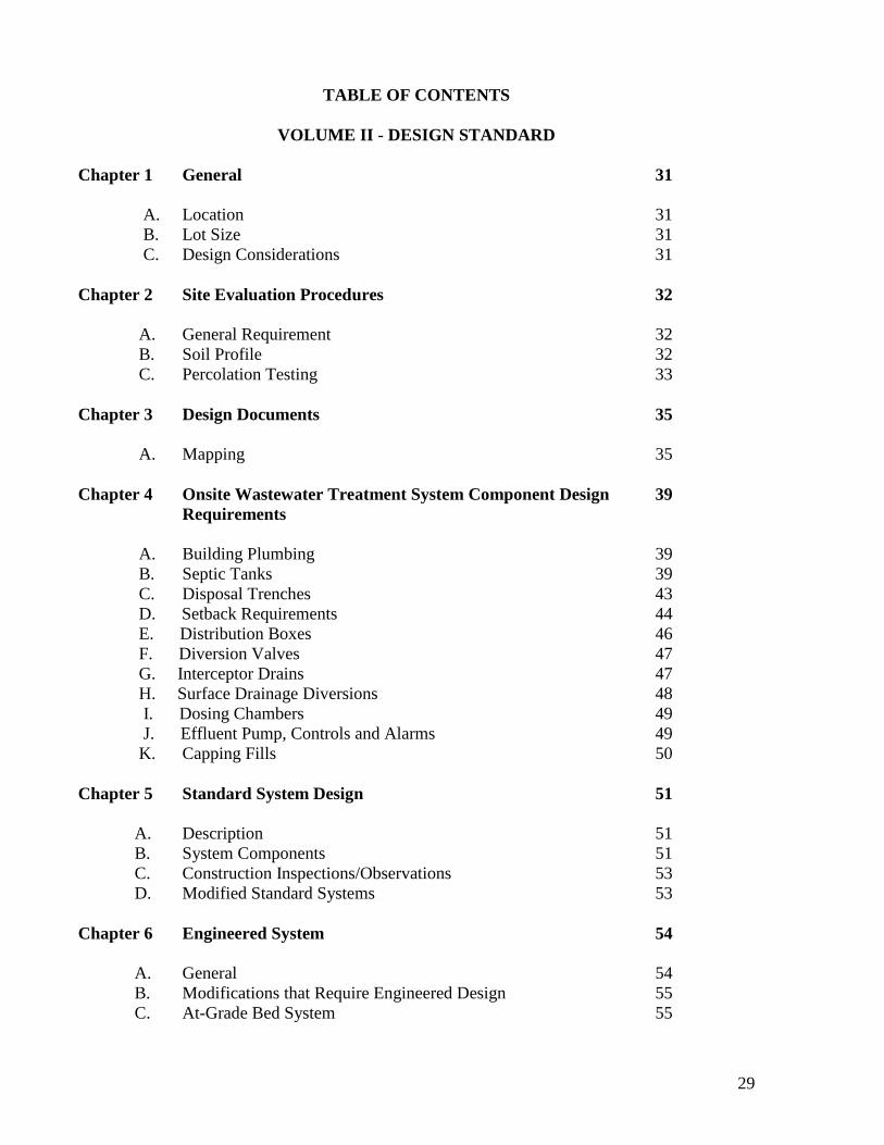
TABLE OF CONTENTS
VOLUME II - DESIGN STANDARD
Chapter 1 General 31
A. Location 31
B. Lot Size 31
C. Design Considerations 31
Chapter 2 Site Evaluation Procedures 32
A. General Requirement 32
B. Soil Profile 32
C. Percolation Testing 33
Chapter 3 Design Documents 35
A. Mapping 35
Chapter 4 Onsite Wastewater Treatment System Component Design 39
Requirements
A. Building Plumbing 39
B. Septic Tanks 39
C. Disposal Trenches 43
D. Setback Requirements 44
E. Distribution Boxes 46
F. Diversion Valves 47
G. Interceptor Drains 47
H. Surface Drainage Diversions 48
I. Dosing Chambers 49
J. Effluent Pump, Controls and Alarms 49
K. Capping Fills 50
Chapter 5 Standard System Design 51
A. Description 51
B. System Components 51
C. Construction Inspections/Observations 53
D. Modified Standard Systems 53
Chapter 6 Engineered System 54
A. General 54
B. Modifications that Require Engineered Design 55
C. At-Grade Bed System 55

30
D. Mound System 57
E. Gravel Filled Pressure Distribution System 60
F. Sand Filled Pressure Distribution System 61
G. Advanced Treatment Systems with Pressure Distribution Trenches 62
H. Temporary Individual OWTS’s 63
I. Package Wastewater Treatment Plants 65
J. Proposals for Experimental Systems 67
K. Subsurface Drip Disposal/Drip Systems 67
L. Easements 68
Chapter 7 Waste Discharge Requirements 68
A. Residential Units 68
B. Commercial/Industrial Units 69

31
VOLUME II - DESIGN STANDARDS
CHAPTER 1 - GENERAL
A. Location
The location, installation and maintenance of the OWTS and each part thereof shall be such that
it will function in a sanitary manner and will not create a nuisance or endanger the quality of any
water. Consideration shall be given to the size and shape of the lot, location of building, slope of
ground surface, soil depth and character, depth to groundwater, proximity of existing and/or
future water supplies and expansion of system or connection to future public wastewater delivery
systems.
B. Lot Size
Net useable area shall be identified demonstrating that lot size is sufficient to permit proper
location, installation and operation of the OWTS. The average daily quantity of wastewater, the
character of surface and subsurface land features, and the source of the water supply will
determine the necessary lot size. Minimum lot size as expressed in net area must be sufficient to
provide compliance with all setback requirements as defined in these regulations.
C. Design Considerations
Design of the OWTS shall include the following considerations:
1. The OWTS shall be designed to receive all domestic wastewater from the property. No
basement, footing or surface drainage or regeneration discharge from water softeners shall be
permitted to enter any part of the OWTS.
2. Where all requirements may be met and available area permits, the OWTS shall consist of a
standard system.
3. All designs submitted shall contain complete and accurate information to allow the
Department to fully evaluate the suitability of the proposed system for the intended site.
4. The minimum number of bedrooms used in sizing an OWTS shall be two (2).
CHAPTER 2 - SITE EVALUATION PROCEDURES

32
A. General Requirements
Site evaluations for determining the suitability of a parcel for OWTS disposal shall consist of
mapping, soil mantle profile testing, percolation testing and/or other site evaluation procedures
that may be deemed appropriate by a qualified professional. Testing performed prior to the
adoption of the last revised and adopted version of these regulations may be acceptable if
performed and recorded in conformance with the requirements of these regulations.
B. Soil Profile
1. Location
At least four profile holes are required, two in the primary disposal area, and two in the
expansion/replacement area.
2. Dimensions
Profile holes must be at least twenty-four (24)-inches wide. A thirty-six (36) inch width is
preferred. The hole shall be excavated by mechanical means to a minimum depth of eight (8) feet
or practical refusal. On one side of the excavation, a three (3) foot wide "shelf" shall be
constructed at a depth between fifty-four (54) and sixty (60) inches. A ramp at a maximum slope
of two and one half (2 ½) to one (1) shall be constructed to allow access to the “shelf” area for
direct observation of the soil profile. A sketch of a typical profile hole follows. In caving soils
the "shelf" and access ramp may be omitted.
Profile-hole development shall comply with safety requirements set forth in Title 8 of the
California Code of Regulations.
3. Soil Mantle Log
The qualified professional when applicable shall prepare a detailed and complete log of soil, rock
and moisture conditions encountered for each profile hole. United States Department of
Agriculture (USDA) classification methods shall be used. Soil samples may be collected as
necessary for laboratory analysis.
4. Reporting
A qualified professional when applicable shall submit soil mantle profile testing results to the
Department together with the following information:
a. date of testing.
b. the approximate location and orientation of each profile.
c. the slope and direction at each profile.

33
d. a description of the prominent soil horizons including depth, estimated
volume of rock fragments, texture, color, mottles, structure, field moisture,
consistency, presence of clay films, estimated permeability and boundary
description for each profile.
e. estimated effective soil depth of each profile.
f. estimated or actual depths to temporary and permanent groundwater tables.
g. The signature and seal of the responsible qualified professional when applicable.
C. Percolation Testing
Following County review of the results and recommendations from the soil mantle profile testing
in item C.4., above, the County may waive the requirement for percolation testing. Where
percolation testing is waived, OWTS design shall be based on the approved design criteria from
the soil mantle investigations. Designers are advised that percolation testing is used as a tool for
site evaluation and not necessarily as an absolute rule for justifying the suitability of an area.
Modification of the percolation testing depth or procedures may be required in unusual
circumstances. When the requirement for percolation testing is not waived, procedures shall
conform to the following:
1. Location
A minimum of six percolation tests must be performed including three in the primary area and
three in the reserve area. Additional testing may be required when the results of the initial
testing indicate highly variable percolation rates.
2. Dimensions
a. Percolation test holes shall be eight (8) inches in diameter. As near as the actual soil
conditions permit, the sidewalls of the test hole shall be vertical and the bottom shall be
horizontal.
b. The depth of a percolation test hole shall be measured from a straight edge placed parallel
to the slope of the ground over the center of the hole to the bottom of the hole.
c. The minimum average hole depth shall be equal to or greater than the maximum disposal
system trench depth, measured from the greatest trench sidewall depth. The number of
holes deeper than the trench bottom depth shall be equal to or greater than the number of
holes shallower than the trench bottom depth.
d. The minimum depth of an actual test hole placed in the bottom of a larger hole, such as a
backhoe cut, shall be twelve (12) inches.
3. Hole Preparation

34
The bottom and sides of the test hole shall be scarified to remove smears and areas of compacted
soil. All loose material shall be removed from the test hole. Either a four (4) inch or six (6) inch
diameter perforated pipe shall be centered in the hole and surrounded by pea gravel to a
minimum depth of twelve (12) inches. The pea gravel need not be placed over the bottom of the
hole inside the pipe.
4. Presoak
A minimum water depth of twelve (12) inches shall be maintained in the test holes for a
minimum of four (4) hours, between twelve (12) and twenty-four (24) hours prior to testing.
Water should be added to the hole along the outside of the pipe.
5. Percolation Test Apparatus
Water level readings shall be made using a separate fixed flotation device for each hole. A sketch
of one type of device is attached, however, other types of apparatus may be accepted.
6. Test Procedure
The test hole shall be filled / adjusted to a water depth of between six (6) inches and eight (8)
inches above the bottom of the hole. Water level readings shall generally be taken and recorded
at thirty (30) minute intervals for four (4) hours or until three successive readings vary by no
more than one-sixteenth (1/16) of an inch. A minimum of three readings shall be taken. The
water level shall be adjusted whenever a reading indicates that the water level is less than six (6)
inches above the bottom of the hole.
The time interval between measurements may be adjusted to be shorter for faster percolation
rates or longer for slower rates to allow the water depth to be maintained between six (6) inches
and eight (8) inches above the bottom of the hole.
7. Rate Calculation
The percolation rate is calculated for each test hole by dividing the time interval used between
measurements by the magnitude of the smallest of the final three successive readings of water
level drop. The calculated results for a percolation rate shall be expressed in terms of mpi.
8. Reporting
a. The percolation data sheet shall, at a minimum, contain the following information:
(1) Lot number, subdivision and APN.
(2) Signature and seal of responsible qualified professional and name of person
conducting test(s).
(3) Date of test.
(4) Depth of holes.

35
(5) Units of measurements.
(6) Gravel-pack pipe size if other than four (4) inch diameter.
(7) A reasonable method of tabulation for recording the data.
(8) A brief sketch showing the relative location of the test holes (may be placed on the
back of the data sheet) with a tie to a known point (such as a property corner) which
will also be referenced on the plot plan.
(9) Third Party Review.
Third party testing and/or review may be required at the discretion of the Agency Administrator.
CHAPTER 3 - DESIGN DOCUMENTS
A. Mapping
1. Accuracy
All mapping of OWTS areas shall be sufficiently accurate to allow for adequate design, plan
review and construction. The minimum accuracy is plus or minus one (1) foot horizontal location
and plus or minus one tenth (0.1) foot vertical location. For large parcels [over five (5) acres],
less accurate mapping is acceptable for the entire parcel provided more detailed mapping is
provided in the immediate area of the building(s) and OWTS.
2. Basis of Plans
While every effort should be made to locate four recorded monuments, a minimum of at least
two (2) recorded monuments shall be used as a basis for plan preparation (all recorded
monuments shall be designated as being found or not found on the plans).
3. Scale
For parcels less than three-fourths (3/4) acres in size the scale shall be one (1) inch equals ten
(10) feet and for all larger parcels the scale may be either one (1) inch equals ten (10) or twenty
(20) feet.
4. Contour Interval
Sufficient field survey data shall be taken for the accurate plotting of existing contour lines as
follows:
a. For plans with a one inch equals ten feet (1" = 10') scale and an average slope of less than
ten (10) percent, and plans with a one inch equals twenty feet (1" = 20’) scale and an
average slope less than five (5) percent the contour interval shall be two (2) feet.

36
b. Otherwise, the contour interval may be five (5) feet or two (2) feet.
c. All bench mark location(s) and all established reference points must be
accurately noted.
5. Features to Be Identified
a. Indicate the location of property lines, all profile excavations and percolation tests,
easements, proposed wastewater disposal area including expansion area, trees greater
than twelve (12) inches in diameter located in the proposed disposal areas, proposed
building locations, driveways, edge of paved road(s), and cut banks and fill banks with
vertical height noted in one (1) foot increments.
b. Indicate the location of each of the following which are located on the property or within
the distances specified outside of the property lines:
edge of culvert, or seasonal drainage course 50 feet
water supply well 100 feet
pond, lake or reservoir 200 feet
flowing stream or river with pretreatment* 50 feet
flowing stream or river without pretreatment* 100 feet
* Distance to be measured from one-hundred (100) year floodplain if available. In cases
where floodplain data is not available, distance to be measured from the known high
water mark.
c. Other surface features on the property or on nearby property which may affect the siting,
design or operation of the OWTS.

37

38
Calaveras County
Onsite Wastewater Department
Typical Percolation Test Apparatus

39
CHAPTER 4 - ONSITE WASTEWATER TREATMENT SYSTEM COMPONENT
DESIGN REQUIREMENTS
A. Building Plumbing
1. All building plumbing shall be installed in accordance with the California Plumbing Code,
latest edition, as interpreted by the Calaveras County Building Official.
B. Septic Tanks
1. Plans for all prefabricated septic tanks shall be submitted to the Calaveras County Onsite
Wastewater Treatment Department for approval. Such plans shall show all dimensions,
reinforcing, structural calculations and such other pertinent data as may be required.
2. All concrete septic tanks intended for use in the County shall be monolithic and shall be
constructed of sound durable material. Non-concrete tanks may be constructed of IAPMO
approved or equivalent materials not subject to excessive corrosion or decay. All tanks shall be
watertight such that when filled to operating depth there is no measurable drop in water surface
over a twenty-four (24) hour test period. Each such tank shall be structurally designed to
withstand all anticipated earth or other loads and shall be installed level and on a solid bed. In
high groundwater areas, septic tanks shall be filled immediately to prevent floatation when
empty.
3. The minimum compressive strength of any concrete septic tank wall or floor shall be two-
thousand (2,000) pounds per square inch. Concrete septic tank covers shall be reinforced and
shall have a minimum compressive strength of twenty-five hundred (2,500) pounds per square
inch. All septic tank covers shall be capable of supporting an earth load of not less than three-
hundred (300) pounds per square foot when the maximum coverage does not exceed three (3)
feet.
4. Septic tanks shall have a minimum of two (2) compartments. The inlet compartment of any
septic tank shall not be less than two-thirds (2/3) of the total capacity and length of the tank.
Access to each compartment shall be provided by a manhole twenty-two (22) inches in minimum
dimensions. Access risers to manholes shall extend to the ground surface. The ground surface
immediately surrounding the septic tank shall be graded to prevent surface water from ponding
over or entering the septic tank.
5. The recommended liquid depth of the septic tank shall be four and one half (4 1/2) feet with a
maximum depth of six (6) feet. The length of the septic tank shall be at least two (2) times the
width. The air space above the liquid depth shall be approximately one (1) foot. There shall be a
clearance of two (2) inches between the cover and all partitions and baffles.
6. The specifications and installation procedures for cast-in-place septic tanks shall be
determined by a Registered Civil Engineer.
7. A four (4) inch inlet tee shall be vented, sized as per the California Plumbing Code, and shall
extend approximately six (6) inches above the water surface and twelve (12) inches below the
water surface of the tank.

40
8. A four (4) inch outlet tee shall be vented, and extend at least six (6) inches above and eighteen
(18) inches below the water surface.
9. The invert of the inlet pipe shall be at least two (2) inches above the invert of the outlet pipe.
10. Design of the septic tank shall assure uniform horizontal wastewater flow throughout its
entire length. (Side connections to septic tanks may be approved if located within one (1) foot of
the end of the tank.)
11. The septic tank shall be at least five (5) feet from a property line or a structure.
12. The septic tank shall be located to provide access for maintenance and cleaning (pumping)
equipment.
13. The required minimum capacity of the septic tank for dwellings shall be based on the number
of bedrooms contemplated or existing. The following table shall be used for computing septic
tank capacities for dwellings.
Number of Bedrooms Capacity
a. 2–3 bedrooms 1200 gallons
b. 4 bedrooms 1500 gallons
c. 5 bedrooms 2000 gallons
14. Multiple family residences and apartment houses shall have no more than four (4) units per
septic tank without approval of a package treatment plant or an engineered system by the County
and the Regional Water Quality Control Board – Central Valley Region.
15. Required septic tank size for commercial establishments or multiple family residences shall
be one-thousand, five-hundred (1,500) gallons or one-thousand, one-hundred twenty-five (1,125)
gallons + 0.75Q (where Q equals maximum daily flow), whichever is greater. Large septic tanks
[over two-thousand, five-hundred (2,500) gallons] shall be designed to reduce solids washout
during peak flows.
16. Where specific flow information is not available, alternative sources of information,
including the EPA Manual “Onsite Wastewater Treatment and Disposal Systems”, Appendix I of
the latest edition of the California Plumbing Code, Small and Decentralized Wastewater
Management Systems by Crites/Tchobanoglous or the following Wastewater Flow Table may be
used as guidelines for non-residential establishments:

41
Type of Establishment Gallons per Capita per Day (gpcd)
1. Rooming Houses 50 gpcd
2. Boarding Houses 60 gpcd
3. Motels without private baths 50 gpcd
4. Hotels with private baths 60 gpcd
5. Restaurants (use highest figure) 25 gpcd or 75 gal/seat
6. Restaurants and Cocktail Lounges 35 gpcd or 100 gal/seat
7. Bars or Cocktail Lounges 20 gal/seat
8. Tourist Camps with central bath house 60 gpcd
9. Tourist Camps with individual bath units 75 gpcd
10. Luxury Camps 100 gpcd
11. Work or Construction Camps (semi permanent) (per shift) 50 gal/person/shift
12. Day camps (no meals served) 30 gpcd
13. Schools without cafeterias, gyms and showers 30 gpcd
14. Schools with cafeterias, gyms and showers 50 gpcd
15. Boarding Schools 100 gpcd
16. Day Workers at Schools and Office Buildings 30 gpcd
17. Hospitals (per bed) 250 gal/per bed
18. Institutions other than Hospitals (involuntary) 175 gal/per bed
19. Factories per shift, with food facility (exclusive of industrial wastes) 25 gpcd
20. Factories per shift, without food facility (exclusive of industrial wastes) 15 gpcd
21. Picnic Parks (toilet wastes only) (gallons/picnicker) 25 gpcd
22. Picnic Parks w/bath house, showers flush toilets 40 gpcd
23. Swimming pool and bath houses 25 gpcd
24. Country Clubs, per resident member 100 gpcd
25. Motels, per bed 50 gpcd
26. Motels (w/kitchens), per bed 60 gpcd
27. Drive-in Theatres, per car space (including snack bar) 10 gpcd
28. Movie Theatres, per auditorium seat (including snack bar) 10 gpcd
29. Airports, per passenger 50 gal/plumbing fixture
30. Self-service laundries, per machine 400 gal/machine
31. Stores, per toilet fixture (employee and public use) 50 gal/fixture
32. Service Stations (per vehicle served) 10 gpcd
33. Public gathering (auction, ball games, fairs, etc.) 10 gpcd
34. Food Preparation (wholesale) 250 gal/employee/shift
35. Churches – no kitchen 5 gal/seat
36. Churches – with kitchen 10 gal/seat
37. Kennels (use highest total ) 16 gal/cage or 10 gal/dog

42
17. Fiberglass or polyethylene septic tanks shall be IAPMO approved or equivalent.
18. Installation of Septic Tanks
a. Tanks are to be installed on a solid base and shall be level. The tank shall have removable
covers or manholes and access risers. The combination of tank covers and access risers
must be constructed and attached to the tank in such a manner as to preclude infiltration
of surface water into the tank. Risers shall be at least twenty-four (24) inches in minimum
dimension and shall be bolted securely in place. All access risers shall have water tight
lids that are securely bolted in place. The lids must also prevent release of gases.
b. The minimum depth of soil cover on a septic tank shall be twelve (12) inches. There is
not a maximum depth of soil cover on a septic tank. Depths in excess of thirty-six (36)
shall require an assessment by a Registered Civil Engineer.
c. Backfilling around a septic tank shall be accomplished in a manner to prevent settlement
and avoid undue strain on the tank and the pipes entering and leaving the tank. Cast iron
pipe or high strength plastic pipe (Sch. 40 PVC or Sch. 40 ABS) shall extend from the
septic tank for a distance of at least five (5) feet from the inlet and outlet ends and must
be adequately supported to prevent failures as a result of settling.
d. Fiberglass or polyethylene tanks shall be filled to the top with water to prove water
tightness before the tank is backfilled.
e. Fiberglass or polyethylene tanks shall be installed as per manufacturer specifications and
instructions.
19. Destruction of a Septic Tank
When a septic tank is to be destroyed in place, the tank shall be pumped by a County
recognized registered pumper. The tank shall then be destroyed in a manner to prevent
accumulation of water and backfilled with sand or clean soil.
20. Grease Interceptor
A grease interceptor shall be required whenever any commercial food establishment or
any other establishment produces quantities of grease greater than the normal content
produced in domestic wastewater. If part of a public wastewater delivery system, the
grease interceptor must be approved by the local utility.

43
C. Disposal Trenches
1. Disposal Trench Configuration
Disposal trenches in the disposal field shall be of the same width and shall meet the following:
a. Maximum length of individual
gravity fed disposal trenches 100’
b. Minimum width of trench 12”
c. Maximum grade of gravity fed distribution pipes 3” per 100’
d. Preferable grade of gravity fed distribution pipes 2” per 100’
e. Minimum distance between trenches: 10 ft. center to center
- May be reduced for repairs, minimum distance: 7 ft. center to center
f. Minimum depth of filter material below distribution pipe 6”
g. Minimum depth of filter material over distribution pipe 2”
h. Minimum soil depth below trench bottom over filter material including capping fill
material if any varies with design
i. Minimum depth of soil cover 12”
j. Maximum depth of soil cover 30”
Reductions in trench spacing may be considered on a case by case basis by the Agency
Administrator.
2. Observation wells
Observation wells shall be placed at each end of each continuous disposal trench. The
well shall be solid plastic pipe with cap, a minimum of four (4) inches in diameter and
slotted or perforated in the gravel horizon of the trench. The observation well pipe shall
extend through drainrock to bottom of trench or bed and also extend a minimum of six
(6) inches above finished grade or shall be set slightly below finished grade and marked
with a ferrous rod which has a minimum length of twelve (12) inches and a minimum
diameter of three-eights (3/8) of an inch.
3. Distribution Pipes
a. The perforated distribution pipe for gravity-fed standard OWTS’s shall be of four (4)
inch inside diameter of Acrylonitrile-Butadiene-Styrene (ABS), clay, concrete,
polyethylene (PE), polyvinyl chloride (PVC) (1,000 pound minimum crush) with
American Society for Testing and Materials (ASTM) approved and in accordance with
California Plumbing Code (CPC) standard, or equivalent.
b. Perforations shall be five-eights (5/8) inch diameter and placed down in the trench. Ends
of distribution pipe shall be capped.
c. When pressure pipe is used, it shall be specified by the qualified professional and
designed for the particular application with a design pressure rating greater than one and
one half (1-1/2) times the maximum working pressure. The minimum standard shall be
equal to ASTM schedule 40 PVC. PVC pressure lateral risers (inspection risers) shall be

44
protected by being placed in a sleeve pipe or yard box or shall be set slightly below
finished grade and marked with a ferrous rod which has a minimum length of twelve
(12) inches and a minimum diameter of three-eights (3/8) of an inch. Lateral risers shall
be equipped with a forty-five (45) degree elbow or sweep.
d. Distribution pipes shall not be placed under concrete, blacktop, roadway or structures. If
necessary to cross under such construction, water tight lines of material acceptable for
the house sewer shall be used. Orangeburg pipe or concrete jointed pipe is not
acceptable for such crossings.
4. Filter material
Filter material shall be graded and washed rock or other approved material. Not more than five
(5) percent by weight shall pass a number ten (10) sieve.
a. Rock used for filter material shall be three-quarter (3/4) to two and one-half (2-1/2)
inches in diameter.
b. Filter material shall be free of twigs, leaves or other organic debris.
c. The filter material shall be protected from the soil backfill by untreated building paper,
filter fabric or other approved materials.
d. Before placing filter material in a trench, all smeared or compacted surfaces shall be
raked, and loose material removed. Walking in disposal trenches is strongly discouraged
as foot traffic can have the effect of compacting infiltrative surfaces impeding
permeability.
D. Setback Requirements
1. The minimum setback distance from the components of an OWTS shall be as follows:
Disposal
Minimum Septic Tank Field
Horizontal & Other & Other
Distances Treatment Disposal Measured
Required From Units Units From_________
Any water supply well (private) 100’(1) 100’ Center of well
Any water supply well (public) 150’ 150’ Center of well
Water supply pipes (on-site) 10’ 10’ Center of pipe
Flowing steams (2) 50’ 100’(3) 10-yr flood line
Private lake or reservoir 50’ 200’(4) Normal high water line
Public water supply, lake, reservoir
or flowing water body 200’ 200’(14) (high water mark)
Property line < five acres 10’ 10’(5) Edge of tank or trench/bed
Property line > five (5) acres 50’(12) 50’(12) Edge of tank or trench/bed

45
Buildings or structures on
continuous or pier foundations 5’(13) 10’(6) Outside edge of foundation
Distribution box 3’ 5’ Edge of box
Disposal Field 5’ - Edge of trench/bed
Seasonal drainage course 25’ 50’(7) Edge of bank
Driveway, patio or other
hard surface (9) - (8) 10 (9) Edge of feature
Cutbanks 10’ 4 x ht. (10) Top edge of cut
Utility/Road easements - (11) - (11) Outside line of easement
Swimming pools 10’ 25’ Outside edge of pool
Where the effluent disposal area is within 1,200 feet from a public water systems’ surface water
intake and within the catchment of the drainage, the disposal area shall be no less than 400 feet
from the high water mark of the lake, reservoir or flowing water body.
Where the effluent disposal area is located more than 1,200 feet, but less than 2,500 feet from a
public water systems’ surface water intake and within the catchment area of the drainage, the
disposal area shall be no less than 200 feet from the high water mark of the lake, reservoir or
flowing water body.
All minimum distances shall be measured on the horizontal.
(1) Setback may be reduced from one-hundred (100) to fifty (50) feet for repairs on parcels
developed prior to February 15, 1990.
(2) Setbacks may be reduced to those associated with a Seasonal Drainage Course provided that
the stream does not flow continuously and the upslope drainage basin of the stream is less than
six-hundred forty (640) acres.
(3) The Agency Administrator may approve a setback of fifty (50) feet when the disposal field is
preceded by a Department approved pretreatment unit, based upon a written site specific
evaluation-provided by a qualified professional.
(4) Staff may consider/approve a setback of one-hundred (100) feet on a case by case basis. The
Agency Administrator may approve a setback of fifty (50) feet when the disposal field is
preceded by a Department approved pretreatment unit, based upon a written site specific
evaluation provided by a qualified professional.
(5) When the effective soil depth is less than thirty-six (36) inches, the setback to down slope
adjacent parcel property line shall be fifty (50) feet, unless otherwise recommended by a
qualified professional based on a site specific evaluation. The Agency Administrator may
approve a setback of five (5) feet based upon a site specific evaluation.
(6) Setback may be reduced to five (5) feet from deck piers. Tanks may be placed on the inside
edge of deck piers when it can be demonstrated that there is clearance for servicing of tank and
the installation will not compromise the structural integrity of the pier(s) as confirmed by a
qualified professional. These shall be considered on a case by case basis only.

46
(7) The minimum setback to a naturally occurring seasonal drainage course may be reduced to
twenty-five (25) feet when the drainage is routed in non-pressure rated piping (such as
corrugated metal pipe). The minimum setback to a man-made seasonal drainage course may be
reduced to ten (10) feet when the drainage is routed through an approved high density
polyethylene or other approved water tight material. A design for the drainage structure shall be
developed by those qualified professionals that are licensed by the State of California to size
drainage structures and shall be developed pursuant to the Calaveras County Public Works
department standards. A design for the drainage structure shall be submitted together with the
OWTS design for review and approval. Agency Administrator may approve a setback of twenty-
five (25) feet when the disposal field is preceded by a Department approved pretreatment unit,
based upon a written site specific evaluation provided by a qualified professional.
(8) Septic tanks installed under hard surfaces shall have manhole risers to grade and shall be
designed for maximum anticipated vehicle load.
(9) Setback may be reduced to five (5) feet where site/soil conditions are suitable for the
installation of a standard system.
(10) For cut-banks where the effective soil depth is less than forty-eight (48) inches the
minimum setback shall be fifty (50) feet, unless otherwise recommended by a qualified
professional based on a site specific evaluation. For cut-banks where the effective soil depth is
forty-eight (48) inches or greater, maximum required setback shall be fifty (50) feet.
(11) Treatment and disposal units shall not be placed in an easement unless otherwise authorized
and approved by said utility or other authorized authority.
(12) The agency Administrator may consider/approve a reduction in the 50’ setback for repairs
on a case by case basis.
(13) Tanks may be placed on the inside edge of deck piers when it can be demonstrated that
there is clearance for servicing the tank and the installation will not compromise the structural
integrity of the pier(s) as confirmed by a qualified professional.
Reductions in setbacks may be considered on a case by case basis by the Agency Administrator.
E. Distribution Boxes
1. Distribution boxes shall be constructed of concrete, plastic, fiberglass or other decay
resistant materials approved by the Department.
2. Distribution boxes, when used, must be set level on a poured concrete pad on undisturbed
earth to prevent settling.
3. Distribution boxes shall be watertight, shall be installed to prevent the inflow of surface
water, and shall be designed to accommodate the necessary distribution laterals. Boxes
shall be specifically designed and installed to achieve uniform flow distribution between
all outlets.

47
4. Outlet inverts shall be at least two (2) inches below the inlet invert.
5. Serial distribution will be accomplished by using twenty-two (22) degree elbows
connected to solid crossover pipes to successive-trenches. The bottom of the elbow shall
not be at a lower level than the top of preceding distribution pipe. "Drop-box"
arrangements may be designed as an alternative for serial distribution.
6. Designs of special distribution structures which require unequal distribution among the
various outlets shall include hydraulic computations supporting the design for
Department review.
F. Diversion Valves
1. Diversion valves shall be constructed of durable materials and of a design approved by the
Department. Valves shall be intended for use with wastewater, shall be corrosion resistant, and
shall be watertight.
2. All diversion valves shall have a positive stop at all operating positions (i.e. full-open and
full-closed or outlet 1 and outlet 2). A handle position which aligns with the active outlet will
comply with this requirement.
3. The manufacturer’s name with make and model number shall be displayed on the valve.
G. Interceptor Drains
1. Where interceptor drains are required, complete design plans shall be prepared by a qualified
professional and submitted to the Department for review.
2. The bottom of the interceptor drain shall be at least twelve (12) inches below the bottom of the
lowest disposal trench or shall extend into a restrictive horizon.
3. The bottom and sides of the interceptor drain closest to the disposal field shall be lined with
single ply polyvinyl chloride (PVC) or polyethylene (PE) plastic film which has a minimum
thickness of twelve (12) mils.
4. The side of the interceptor drain trench farthest from the disposal area and the top of the drain
rock must be lined with an acceptable filter fabric.
5. Four (4) to six (6) inches of clean drain rock or suitable equivalent as approved by the
Department shall be placed in the bottom of the trench and perforated pipe sized for local site
conditions shall be laid over this with the perforations placed down. Drain rock is placed over the
pipe to a depth required by site conditions.
6. Minimum separation shall be maintained between interceptor drains and disposal trenches. In
general, the following separations shall be maintained where site conditions allow:

48
a. A minimum clearance of ten (10) feet must be maintained between an upslope interceptor
drain and a disposal trench.
b. A minimum clearance of twenty-five (25) feet must be maintained between a laterally
located interceptor drain and a disposal trench.
c. A fifty (50) foot minimum separation is required for a down-gradient interceptor drain to
prevent infiltration of the drain with septic tank effluent.
d. Local site conditions may require a larger separation. The setbacks required in G.6 a, b
and c above may be reduced based on a qualified professional’s recommendation
following a site specific evaluation.
e. Down-gradient interceptor drains on slopes over ten (10) percent are generally not
appropriate.
f. The qualified professional shall provide supporting documentation for the design.
7. House downspouts and drainage from paved areas shall be connected to the interceptor drain
whenever possible.
8. The interceptor drain shall discharge by gravity to the surface and shall include energy
dissipation considerations to prevent local erosion. The outlet shall be designed for ease of
sampling the discharge, and shall be equipped with a perforated cap, stainless steel screening or
other method to preclude entry of rodents or other small animals.
9. The applicant is solely responsible to obtain any other permits or approvals which may be
necessary due to construction of any interceptor drain systems.
H. Surface Drainage Diversions
1. For disposal trenches designed in concave land forms or in areas where there is less than forty-
eight (48) inches of effective soil depth, surface diversion ditches shall be designed to intercept
sheet flow runoff from above the disposal field to reduce saturation conditions in the disposal
area.
2. Surface diversion trenches shall be designed to minimize erosion.
3. Roof leaders, downspouts, irrigation systems, or other sources which concentrate water shall
be diverted away from disposal areas.
4. The applicant is solely responsible to obtain any other permits or approvals which may be
necessary due to construction of any surface drainage diversion systems.

49
I. Dosing Chambers
1. Dosing chambers shall be monolithic, watertight and constructed of corrosion resistant,
durable materials as approved by the Department. Chambers shall be designed for the soil and
groundwater conditions at the intended site, including buoyant conditions when the chamber is
empty.
2. Inlet and outlet materials shall be schedule 40 PVC, ductile iron or other durable material
approved by the Department. Inlets and outlets shall be supplied with a rubber or neoprene
gasket or grommet.
3. Each dosing chamber shall have a watertight riser extending to the ground surface with a
minimum dimension of twenty-four (24) inches. The risers shall be centered over an access
manhole with a minimum dimension of twenty-two (22) inches.
4. The local ground surface shall be graded to prevent surface water from entering the access
riser.
5. Dosing chambers fitted with one or more pumps shall have a volumetric capacity sufficient to
deliver the design dose between the "pump on" and "pump off" levels. An audio-visual high
water alarm shall be provided above the "pump on" level. A reserve capacity (emergency
storage) shall be provided above the high water alarm level. The minimum reserve capacity shall
be determined by the qualified professional on a design specific basis. Use of the reserve
capacity shall not cause the tank to overflow or a backwater condition in the building sewer.
6. When the septic tank is proposed to be directly equipped with one or more pumps or a siphon
for dosing, the septic tank shall be oversized to provide minimum septic tank volumes below the
"dose off” level. The baffle dividing the two septic tank chambers shall be designed such that the
dose drawdown is limited to the outlet chamber.
7. A dose counting device shall be provided with all dosing systems.
8. All supplemental treatment systems shall have a separate pump tank. The tank shall be not
less than one-thousand (1000) gallons to allow for emergency storage. The storage capacity may
be reduced when a tank is integrated as part of the supplemental treatment unit. These shall be
considered on a case by case basis only.
J. Effluent Pump, Controls and Alarms
1. All electrical components used in OWTS’s shall comply with the California Electrical Code
and the requirements of the Calaveras County Building Department.
2. Pumps shall be rated for wastewater application.
3. Motors shall be rated for continuous duty and shall be provided with overload protection.
4. Submersible pumps shall have a non-corrosive lifting device to allow ease of removal and
service without requiring entry into the pump chamber.

50
5. Pumps shall be equipped with non-clog impellers capable of passing a 3/4 inch solid sphere or
shall be protected by a cylinder of corrosion resistant screen extending above the maximum
effluent level with one-eighth (1/8) inch maximum openings or other approved method.
6. Pumps and alarms shall be activated by sealed float switches, or other reliable devices
approved by the Department. Control floats shall be set such that the volume discharged during
each pump cycle is between fifteen (15) and fifty (50) percent of the design daily flow unless
otherwise dictated by the design of the disposal system.
7. Alarms shall be provided for high water level and may be provided for low water level and
various pump malfunction conditions such as pump seizure or overheating.
8. Alarms shall be both audible and visual. Audible alarms may be user cancellable. Visual
alarms shall require a working knowledge of the control system to cancel such as would be
possessed by a qualified service technician.
9. The alarm annunciator panel shall be located in or adjacent to the building which the pump
system services. The panel shall also be visible and audible from the same structure. If the
system control panel is outdoors, it shall be in an enclosure appropriately rated by the National
Electric Manufacturer's Association.
K. Capping Fills
1. For the purpose of these regulations, "Capping Fill" means a modification to a disposal trench
system by which the minimum required soil cover backfill, twelve (12) inches is obtained by
adding soil above the original ground surface in the disposal area.
2. Capping fills may not be placed on slopes exceeding twenty-five (25) percent. A maximum of
thirty (30) percent may be considered on a case by case basis when a capping fill is designed by
a qualified professional and when the design includes approved erosion control measures and
slope stability.
3. Percolation testing shall be performed a minimum of six (6) inches below the proposed trench
bottom.
4. The minimum depth of a capping fill is three (3) inches. The typical depth is twelve (12)
inches, unless unusual site conditions justify differing depths up to a maximum of thirty (30)
inches.
5. A capping fill shall extend full depth a minimum of five (5) feet upslope or laterally, and a
minimum of ten (10) feet down-slope from the outside edge of the disposal trench.
6. The qualified professional shall specify and verify acceptable soil texture for capping fills, and
shall specify site preparation and other construction details necessary to ensure proper
installation.
7. The perimeter of capping fills shall be smoothly graded to blend with native soil.

51
8. Material for capping fills shall not be obtained from the designated expansion area, or from
down-slope of primary and expansion areas.
CHAPTER 5 - STANDARD SYSTEM DESIGN
A. Description
A standard OWTS serves a single family residence and consists of the building sewer, a septic
tank, a distribution unit, a gravity-fed standard disposal field with observation pipes, and a pre-
identified area which will accommodate a one-hundred (100) percent replacement of the disposal
field, meeting all site conditions and setback requirements. Standard systems may include a
capping fill. See Standard system and Expansion/Replacement area definitions.
B. System Components
1. Standard Trench
a. The standard trench design typically consists of a trench two (2) feet wide by three (3)
feet deep with one and one half (1-1/2) foot sidewall depth below the distribution pipe.
b. Percolation testing may substantiate greater or lesser trench length.
2. Site Criteria
a. Well drained, stable, convex or moderately concave slopes.
b. Slopes < 30%.
c. Able to meet all setback requirements.
d. Vertical separation requirements listed below.
Depth below trench bottom to
Lot size Restrictive Layer
Temporary Water Permanent Water
Less than 2 acres with
community water or 1 to
5 acres with well 36” 30” 60”
Two acres and larger with
community water or 5 acres
and larger with well 24” 30” 60”
3. Design Application Rate

52
Where percolation testing is performed, the design application rate shall be as follows:
Percolation Rate Application Rate
(mpi) (gpd/ sq.ft.)
<1 Not suitable
1 - 5* 0.8
6-15 0.8
16-30 0.8 – 0.6 graduated
31-60 0.6 – 0.45 graduated
61-120 0.45 – 0.2 graduated
>120 Not suitable
*Not suitable without County approval of a report as submitted by a qualified professional on
potential groundwater impacts.
4. Length of Disposal Trench
The minimum total length of disposal trench provided shall be determined by the following
method:
a. Sixty-seven (67) lineal feet per bedroom if no percolation tests are required.
b. When percolation tests are required, the length shall be determined by the following
formula:
L = Q
q x a
L = Minimum total length of disposal trench in feet.
Q = Daily wastewater flow in gallons per day.
q = Application rate in gallons per day per square foot of effective seepage area.
A = The effective seepage area per foot of trench. The maximum value of “A” allowed is five (5)
square feet per lineal foot, except for the repair or replacement of an existing disposal system
which utilizes gravity trenches sized by the Department.
Length of trench is determined by the inclusion of sidewall and bottom area for purposes of
absorption. Sixty-seven (67) lineal feet is based upon the five (5) square feet per lineal foot
value.

53
C. Construction Inspections/Observations
1. Construction verification inspections shall be performed by the Department. The applicant
shall coordinate with the Department to determine when inspections will be required, and
provide at least twenty-four (24) hour advance notice of any required inspections.
2. At the applicant's discretion and cost, a qualified professional may be retained to observe and
certify system construction. A qualified professional shall be retained to perform construction
observations and to provide certification on substantial conformance to the approved design for
all qualified professional designed systems. Twenty-four (24) hour notice shall still be provided
to the Department in advance of burying any system features.
3. In addition to the site investigation profile inspection, the Department shall perform
verification at an open trench inspection and at a final inspection.
4. All specified materials (i.e., tank, rock, and pipe, etc.) must be onsite and the tank(s) in place
at the time of open trench inspection. Additionally, designs requiring drainage alteration must
have all alteration excavations completed and all materials for the alteration onsite at the time of
inspection.
5. Final inspections and observations shall be performed following OWTS completion and prior
to use.
6. Each required inspection shall be recorded on the project inspection record (yellow card) with
the County inspector and qualified professional recording signature and inspection and
observation dates in the appropriate spaces on the card (to eliminate uncertainty about which
inspections and observations have been performed).
D. Modified Standard System
1. For the purpose of these regulations, a "Modified Standard System" means an OWTS
consisting of a septic tank, distribution unit and gravity-fed disposal, trenches with a minimum of
six (6) inches of filter material below the distribution pipe and a minimum of two (2) inches of
filter material and twelve (12) inches of soil backfill above the distribution pipe. The system may
be redundant or may include an effluent pump, and interceptor drain or a capping fill.
2. Minor modifications to a standard OWTS may be made for effective depth, use of a capping
fill, installation of a redundant system or use or a pump system to transport effluent to a gravity
fed disposal field located upslope of the septic tank without requiring engineered OWTS design.
The variations may be approved by the Department subject to findings of suitable site conditions
to support these minor modifications.

54
CHAPTER 6, - ENGINEERED SYSTEMS
A. General
1. All engineered OWTS designs shall be prepared by a Registered Civil Engineer, a Registered
Environmental Health Specialist or a Certified Engineering Geologist. Soil mantle and
percolation testing may be performed by a Registered Geologist in addition to the above
professions.
2. Engineered OWTS designs shall be based on site specific soil conditions. Where initial testing
reveals highly variable physical conditions between profile holes or between percolation test
results, additional testing may be required.
3. All engineered OWTS designs shall include provisions for system monitoring (disposal trench
observation pipes, groundwater monitoring wells, etc.) sufficient to provide information on
system operation. System specific homeowner operation and maintenance guidelines shall be
submitted. These guidelines shall include homeowner procedures to ensure maintenance, repair,
or replacement of critical items within 48 hours following OWTS failure.
4. Since engineered designed systems are frequently installed in areas with shallow or less
permeable soil characteristics, care must be exercised during installation to avoid damage to the
effective seepage area. An OWTS shall not be installed when the installation methods and soil
moisture conditions cause smearing or streaking of the disposal trench sidewall or bottom, or
excessive compaction of soils in the disposal area.
5. All advanced treatment systems shall be designed, installed and maintained pursuant to
manufactures specifications and requirements.
6. Qualified Professional Observations
a. All engineered OWTS installations shall be observed by a qualified professional. All
engineered OWTS design submittals shall include the qualified professional’s
recommended observation schedule, including key points of construction where
notification to the County will be given to allow for County verification of
compliance. The Agency Administrator shall review and approve the observation
schedule as a part of the design. A minimum of a twenty-four (24) hour notice shall
be given to the County for all verification observations required in the approved
inspection schedule.
b. In addition to the soil profile evaluation, the qualified professional shall provide
engineered OWTS observations for the following stages of construction:
a. System layout
b. Open trench/bed rip observation
c. Mechanical/electrical performance observation (where applicable)
d. Uniform distribution observation (where applicable)
e. Final observation of the completed system

55
c. At a minimum the County shall be given twenty-four (24) hour notice of the open
trench and final observations to provide verification.
d. Department final inspection of a completed engineered OWTS shall be performed
following submittal of a letter of certification from the qualified professional stating
the OWTS was observed by the qualified professional and was found to be in
substantial conformance with approved plans.
e. Engineered systems must be constructed as specified on plans. If deviation from
approved plans is necessary, the qualified professional must concur with the changes
and must submit a letter of concurrence with revised plans and revision fee payment.
Construction may continue only after Department review of revised plans is
completed.
B. Modifications that Require Engineered Design
Modifications to a standard OWTS which include interceptor drains, pressure distribution or
other features shall be designed and reviewed as engineered systems.
C. At-Grade Bed System
1. An At-Grade Bed OWTS is designed to uniformly distribute septic tank effluent under
pressure to a disposal bed which has a minimum of six (6) inches of filter material below, and
two (2) inches of filter material and a minimum of twelve (12) inches of soil cover above the
distribution lateral(s). (See the following Typical At-Grade Bed cross section figure).
2. To be considered suitable for an at-grade bed OWTS, the site must have the following
characteristics:
a. A well drained, stable, linear to convex slope.
b. A slope of twenty-five (25) percent or less.
c. Able to comply with all setback requirements.
3. Have a percolation rate less than sixty (60) mpi, determined from testing conducted at a
minimum depth of twenty-four (24) inches below the original ground surface.
4. Able to comply with the following vertical separation requirements.
R5467
Depth below bottom of bed to
Lot size Restrictive Layer
Temporary Water Permanent Water
Less than 2 acres
with community water
or 1 to 5 acres with well 36” 30” 60”

56
Two acres and larger
with community water
or 5 acres and larger with well 24” 30” 60”
3. Required disposal bed length shall be calculated using the following formula:
L = Q
q x w
Q = Daily wastewater flow in gallons per day.
q = Application rate in gallons per day per square feet of disposal area.
w = The width of the disposal bed down-slope of the distribution lateral.
4. Where percolation testing is performed, the design application rate shall be as follows:
Percolation Rate Application Rate
(mpi) (gpd/sq. ft.)
<1 Not Suitable
1 – 30 0.6
31 - 60 0.6 – 0.45 graduated
>60 Not Suitable
5. The gravel bed shall extend a minimum distance of one and one half (1 1/2) feet upslope of the
distribution lateral.
6. An acceptable filter fabric shall be placed between the gravel bed and soil cover.
7. The qualified professional shall specify and verify acceptable texture for soil cover, and shall
specify site preparation and other construction details necessary to insure proper installation and
erosion control.
8. The minimum depth of soil cover over the disposal bed shall be twelve (12) inches. The soil
cover shall extend full depth a minimum of five (5) feet upslope or laterally, and a minimum of
ten (10) feet down-slope from the outside edge of the bed.
9. Borrow areas shall be designated on the plans if soil cover material is to be obtained on site.
Soil cover material shall not be obtained from the designated expansion area, or within fifty (50)
feet down-slope of primary and expansion areas. Pursuant to Section 15.05.080 (F) of County
Code, on site borrow areas are exempt from securing a grading permit however, best
management practices shall be maintained pursuant to Section 15.05.170.
10. A one-hundred (100) percent expansion area shall be provided.

57
11. At-grade bed systems shall be constructed only when the soils are sufficiently dry to resist
compaction and loss of structure when worked.
12. The 2000 “WISCONSIN AT-GRADE SOIL ABSORBTION SYSTEM SITING, DESIGN,
AND CONSTRUCTION MANUAL” is recognized by the Department as an acceptable design
reference, with the exception of specific conflicting requirements listed above.
D. Mound System
1. A "Mound System" is designed to uniformly distribute septic tank effluent under pressure to a
disposal bed raised above the native ground with a minimum of twenty-four (24) inches of
medium sand below the distribution bed and six (6) inches of filter material below, and two (2)
inches of filter material and a minimum of six (6) inches of soil cover above the distribution
laterals. (See the following typical mound cross section figure.)
2. To be considered suitable for a mound system, the site must have the following characteristics:
a. A well drained, stable, linear to convex slope.
b. A Slope of fifteen (15) percent or less.
c. Able to comply with all setback requirements, including an additional ten (10) foot
setback between a building and the toe of an upslope mound for a total of twenty (20)
feet.
d. Have a percolation rate less than sixty (60) mpi, determined from testing conducted at
a minimum depth twenty-four (24) inches below the original ground surface.
e. Able to comply with the following vertical separation requirements.
Depth below bottom of mound to
Lot size Restrictive Layer
Temporary Water Permanent Water
Less than 2 acres with
community water or 1
to 5 acres with well 24” 18” 48”
Two acres and larger
with community water
or 5 acres and larger with well 24” 18” 48”
3. The maximum application rate used to size the distribution bed within the medium sand fill
shall be one and two tenths (1.2) gallons per day per square foot based on bottom area only.
4. The required mound basal area shall be calculated using the following formula:

58
A = Q
q
Where:
A = Mound basal area in square feet and is the product of the length of gravel bed multiplied by
the width of the gravel bed plus the horizontal distance between the gravel bed and the down-
slope toe of the sand fill.
Q = Daily wastewater flow in gallons per day.
q = Application rate in gallons per day per square foot of mound basal area.
5. Where percolation testing is performed the design application rate shall be as follows:
Percolation Rate Application Rate
(mpi) (gpd/sq. ft.)
<1 Not suitable
1 - 30 0.6
31 - 60 0.6 - 0.45 graduated
>60 Not suitable
6. The slope of the sand fill from the top of the gravel bed to the ground surface shall not exceed
three (3) to one (1).
7. An acceptable filter fabric shall be placed between the gravel bed and soil cover.
8. The minimum depth of soil cover over the sand fill and at the edge of the distribution bed shall
be six (6) inches. Soil cover at the center of the distribution bed shall be sufficiently greater to
provide positive drainage from the mound body.
9. The qualified professional shall specify and verify acceptable texture for soil cover, and shall
specify site preparation and other construction details necessary to insure proper installation and
erosion control.
10. Borrow areas shall be designated on the plans if soil cover material is to be obtained on site.
Soil cover material shall not be obtained from the designated expansion area, or from down slope
of primary and expansion areas.
11. Mound systems shall be constructed only when the soils are sufficiently dry to resist
compaction and loss of structure when worked.
12. A one-hundred (100) percent expansion area shall be provided.
13. The "WISCONSIN MOUND SOIL ABSORPTION SYSTEM SITING, DESIGN AND
CONSTRUCTION MANUAL" dated January, 2000 is recognized by the Department as an
acceptable design reference, with the exception of specific conflicting requirements listed above.

59
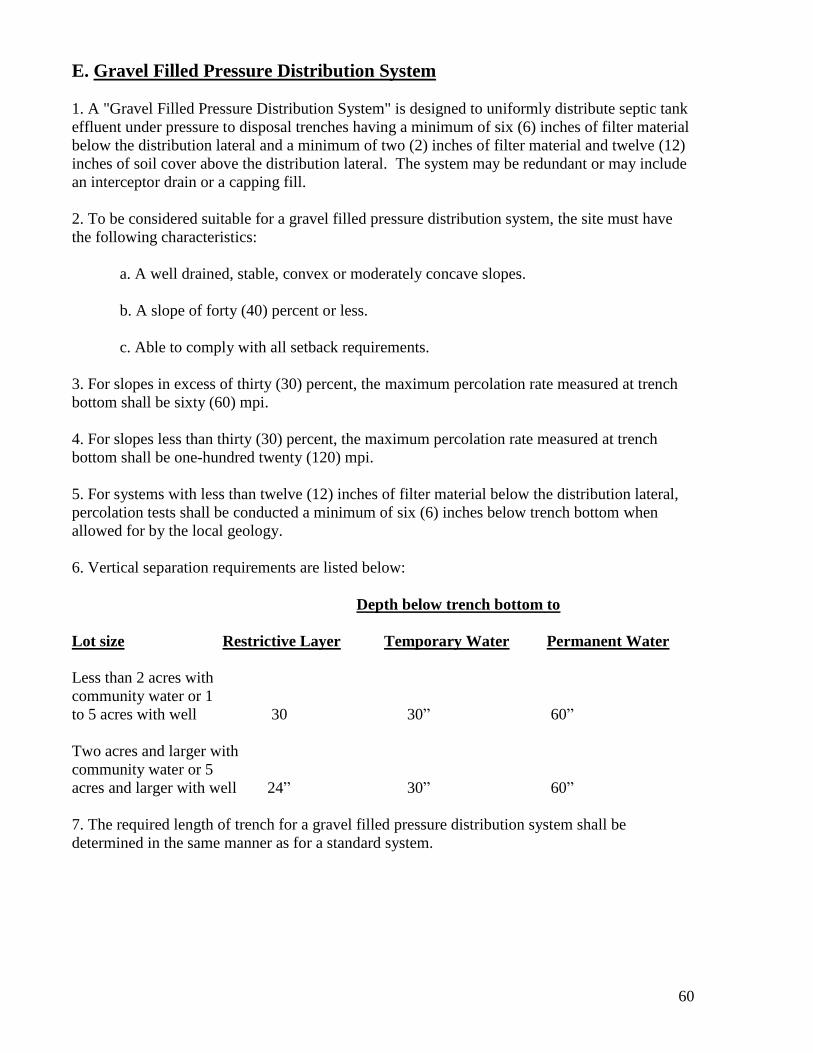
60
E. Gravel Filled Pressure Distribution System
1. A "Gravel Filled Pressure Distribution System" is designed to uniformly distribute septic tank
effluent under pressure to disposal trenches having a minimum of six (6) inches of filter material
below the distribution lateral and a minimum of two (2) inches of filter material and twelve (12)
inches of soil cover above the distribution lateral. The system may be redundant or may include
an interceptor drain or a capping fill.
2. To be considered suitable for a gravel filled pressure distribution system, the site must have
the following characteristics:
a. A well drained, stable, convex or moderately concave slopes.
b. A slope of forty (40) percent or less.
c. Able to comply with all setback requirements.
3. For slopes in excess of thirty (30) percent, the maximum percolation rate measured at trench
bottom shall be sixty (60) mpi.
4. For slopes less than thirty (30) percent, the maximum percolation rate measured at trench
bottom shall be one-hundred twenty (120) mpi.
5. For systems with less than twelve (12) inches of filter material below the distribution lateral,
percolation tests shall be conducted a minimum of six (6) inches below trench bottom when
allowed for by the local geology.
6. Vertical separation requirements are listed below:
Depth below trench bottom to
Lot size Restrictive Layer
Temporary Water Permanent Water
Less than 2 acres with
community water or 1
to 5 acres with well 30 30” 60”
Two acres and larger with
community water or 5
acres and larger with well 24” 30” 60”
7. The required length of trench for a gravel filled pressure distribution system shall be
determined in the same manner as for a standard system.

61
8. A one-hundred (100) percent expansion area located upslope of, or on contour with, the
proposed disposal system shall be provided. If a gravel-filled pressure distribution system is used
on a site with conditions suitable for the installation of a standard system and the parcel was
created prior to March 9, 1981, the minimum required expansion area shall be fifty (50) percent
area.
F. Sand Filled Pressure Distribution System
l. A "Sand Filled Pressure Distribution System" is designed to uniformly distribute septic tank
effluent under pressure to disposal trenches having a minimum of twelve (12) inches of medium
sand and six (6) inches of filter material below, and two (2) inches of filter material and twelve
(12) inches of soil cover above the distribution lateral. The system may be redundant or may
include an interceptor drain or a capping fill.
2. To be considered suitable for a sand filled pressure distribution system, the site must have the
following characteristics:
a. A well drained, stable, moderately concave or convex slope.
b. A slope of forty (40) percent or less.
c. Able to comply with all setback requirements.
3. For slopes in excess of thirty (30) percent, the maximum percolation rate measured at trench
bottom shall be sixty (60) mpi.
4. For slopes less than thirty (30) percent, the maximum percolation rate measured at trench
bottom shall be one-hundred twenty (120) mpi.
5. For systems with capping fill, percolation testing shall be conducted a minimum of six (6)
inches below trench bottom.
6. Vertical separation requirements are listed below.
Depth below trench bottom to
Lot size Restrictive Layer
Temporary Water Permanent Water
Less than 2 acres with
community water, or 1
to 5 acres with well 24" 30” 60”
Two acres and larger with
community water or 5 acre
and larger with well 24” 30” 60”

62
7. Disposal Trench Sizing Criteria
Percolation Rate Design Application Rate
(mpi) (gpd/sq. ft.)
Less than 60 0.45
60 - 120' 0.45 – 0.2 (graduated)
8. For design purposes the maximum effective seepage area shall be four (4) square feet per
lineal foot of trench.
9. A one-hundred (100) percent expansion area shall be provided. The expansion area should be
located upslope of, or on contour with, the proposed distribution system.
G. Advanced Treatment Systems with Pressure Distribution Trenches
1. Recognized Advanced Treatment Systems include Intermittent Sand or other Supplemental
Treatment System as approved by the Department. Other Advanced Treatment Systems may
include, but are not limited to, aerobic systems as considered by the Department on a case by
case basis.
An Advanced Treatment System with Pressure Distribution Trenches” includes gravel filled
pressure distribution systems and recognized Advanced Treatment Systems designed to filter and
biologically treat septic tank effluent for purposes of reducing constituents commonly found in
effluent as defined in these regulations.
Advanced Treatment Systems are used in conjunction with disposal fields where site and soil
conditions are not adequate for standard or engineered systems. These conditions include, but are
not limited to, slowly permeable soils, inadequate depth of effective soil below trench bottom,
and/or inadequate depth to groundwater below trench bottom.
Supplemental Treatment Systems that have been approved by state or nationally recognized
testing agencies (NSF Standard 40 or equivalent) may be approved if they have been found to
adequately protect surface water and groundwater quality and preclude health hazards and
nuisances. All supplemental treatment units shall meet a 50 percent reduction in total nitrogen
when comparing the 30-day average influent to the 30-day average effluent. Supplemental
treatment units designed to perform disinfection shall provide sufficient pretreatment of
wastewater so that effluent does not exceed a 30-day average Total Suspended Solids (TSS) of
30 mg/L and shall further achieve an effluent fecal coliform bacteria concentration less than or
equal to 200 Most Probable Number (MPN) per 100 milliliters.
Allowable types of Supplemental Treatment Systems are as follows: textile filters, intermittent
sand filters, recirculating sand filters and aerobic treatment units. Specific Supplemental
Treatment Systems are subject to county approval
2. To be considered suitable for an Advanced Treatment System with pressure distribution
trenches, the site must have the following characteristics:

63
a. A well drained, stable, moderately concave or convex slope.
b. A slope of thirty (30) percent or less when the percolation rate equals or exceeds sixty
(60) mpi and a slope of forty (40) percent or less when the percolation rate is less than
sixty (60) mpi.
c. Able to comply with all setback requirements.
d. A percolation rate less than two-hundred forty (240) mpi conduced at trench bottom.
For systems with capping fill the test shall be conducted a minimum of six (6) inches
below trench bottom.
3. Vertical separation requirements are listed below.
Depth below trench bottom to
Lot size Restrictive Layer
Temporary Water Permanent Water
Less than 2 acres with
community water, or 1
to 5 acres with well 12" 24” 36"
Two acres and larger with
community water or 5 acres
and larger with well 6" 24” 36"
4. Disposal trench sizing criteria
Percolation Rate Design Application Rate
(mpi) (gpd/sq. ft.)
Less than 30 0.6
31-60 0.6 – 0.45 (graduated)
61-120 0.45 – 0.2 (graduated)
121-240 0.2 – 0.1 (graduated)
The Agency Administrator may approve a twenty-five (25) percent maximum increase in the
above specified application rate based on a written site specific evaluation provided by a
qualified professional.
5. A one-hundred (100) percent expansion area shall be provided.
H. Temporary Individual OWTS’s
1. General Bond
a. Temporary OWTS’s may only be used on an interim basis for a period not to exceed
one year. Such systems may include but are not limited to chemical toilets.

64
b. An OWTS Permit is required prior to construction. Said permit is discretionary and
may be issued only after review and approval by the Agency Administrator.
c. Location of temporary systems shall be such that they cannot discharge, flow, seep or
drain into any surface or groundwater or water intended for human or animal
consumption. The following minimum distances shall be maintained:
(1) From any well 100 feet
(2) From any dwelling 50 feet
(3) From any property Line 10 feet
(4) From water table (temporary 15 feet
or permanent)
2. Chemical Toilets
a. Chemical toilet facilities shall provide sufficient space for comfortable use, a
minimum area of eight (8) square feet with a minimum width of two and one-half (2-
1/2) feet, shall be provided for each toilet seat. A minimum area of ten (10) square
feet with a minimum width of two and one-half (2-1/2) feet, shall be required when a
urinal is included. Sufficient additional space shall be included if hand washing
facilities are within the facility.
b. Chemical toilets shall be designed, constructed and maintained so as to prevent the
access of flies.
c. The inside surfaces of all chemical toilets shall be of durable, non-absorbent material,
smooth, easily cleanable and finished in a light color.
d. Chemical toilets shall be ventilated and provided with self closing doors, lockable
from the inside.
e. The tanks for chemical toilets shall be constructed of durable, easily cleanable
material. Tank size shall be sufficient to contain the initial chemical charge and
provide capacity for at least one day's use for forty (40) persons. Size and
construction shall be such as to prevent splashing on the occupant, field or road while
being transported. A minimum tank capacity of forty (40) gallons shall be provided.
f. Chemicals capable of controlling odors and liquefying solids shall be used in
chemical toilets.
g. Disposal of contents of chemical toilets shall be into a wastewater treatment plant, or
at a disposal site approved by the Director of Environmental Health a copy of a
haulers registration to dispose of waste must be on file with the Environmental Health
Department prior to the rental of any toilets in Calaveras County.
h. Chemical toilets shall be maintained in a clean and sanitary manner, free of odor and
stains.

65
i. Each chemical toilet must be identified with the name of the company and telephone
number. The lettering shall be at least three (3) inches in height and contain other
information as may be required by the Director of Environmental Health.
j. Chemical toilets must be stored at a site approved by the Director of Environmental
Health.
k. Pumper trucks must comply with California Health and Safety Code requirements for
septic tank pumpers.
I. Package Wastewater Treatment Plants
1. Where effluent exceeds 2,500 – 3,000 gallons per day and package wastewater treatment
plants are utilized, complete engineered plans shall be submitted by a Registered Civil Engineer
to the Department for approval prior to beginning construction. Final approval of plans for
package wastewater treatment plants may not be granted until a report of waste discharge has
been filed with the Regional Water Quality Control Board - Central Valley Region and waste
discharge requirements have either been adopted or waived. These plans shall include the
following where applicable:
a. A complete scaled plot plan of the proposed initial and future service areas showing
wells, structures, sanitary wastewater lines, water lines, improved drainage facilities,
topography, surface water features, and proposed land use.
b. Total hydraulic capacity of the plant in gallons per day and treatment capacity expressed
as oxygen demand and solids loading in pounds per day. Design criteria shall include a
reserve capacity to accommodate a surge flow or increase in peak daily flow as well as
the average daily flow.
c. Calculations demonstrating ability of effluent to meet discharge standards as set by the
Regional Water Quality Control Board - Central Valley Region.
d. The source of data and the data calculated to determine plant capacity. Any future
connections to the existing plant or any future expansion of the plant shall be shown on
the plans.
e. The percolation rates of disposal fields shall be calculated and figures shown on the
plans. An expansion area equal in size to the original disposal field shall be so designated
on the plan to be utilized in the event of failure of the original disposal fields. This
expansion area shall pertain to percolation ponds or evaporation ponds as well as
subsurface disposal fields.
f. A hydrologic balance for ponds, lagoons or disposal areas.
g. Detailed operation and maintenance instructions and a list of similar installations
including contact persons and telephone numbers.

66
2. When any existing package wastewater treatment plant is remodeled or altered, or when the
quantity or quality of the wastewater treated changes, all of the above specifications are to be
resubmitted for approval by the Department and the Regional Water Quality Control Board -
Central Valley Region.
3. Mechanical and electrical equipment shall be of such durable hardware, workmanship and
installation as to insure against operational failure with normal maintenance.
4. All installations shall be adequately protected against acts of vandalism or sabotage which
could result in a malfunction of the plant. The entire plant, including any polishing ponds,
percolation ponds and above ground irrigation systems shall be fenced and a locked gate
provided to protect against any unauthorized person gaining entrance into the plant area which
could lead to injury or loss of life.
5. A certified operator with skill to cause the plant to be operated as designed shall be available
to operate the plant. The operator shall be certified by the State of California Water Resources
Control Board-Division of Water Quality Control. The name, operator grade and certificate
number of the person identified as the operator shall be submitted prior to initial plant start-up.
6. Installation of the plant, storage area and disposal system shall be under OWTS Permit and
inspection by the Department. The engineer will be required to certify that the plant was installed
properly.
7. The installation and operation of treatment plants shall not create a public nuisance in regard
to odor nor cause a potential or immediate safety or health hazard to the public. The discharge of
treated effluent shall not cause contamination of any groundwater or surface water.
8. Final disposition of wastewater effluent shall be in constant compliance with the discharge
requirements set by the Regional Water Quality Control Board - Central Valley Region. Any
deviation from these discharge requirements shall be declared a public nuisance and a violation
of these Rules and Regulations.
9. Package wastewater treatment plant tanks are to be installed to required slope and elevation on
properly installed foundations to prevent settling which may cause malfunction or leaking.
10. A grease interceptor shall be required whenever any commercial food establishment is
connected to the plant or any activity which produces grease content over and above the normal
grease content found in domestic wastewater. Grease interceptors shall be required as an addition
to a wastewater treatment plant if it is determined from the analysis of the wastewater influent or
effluent that elevated grease levels prevail.
11. Monitoring by a certified wastewater treatment plant operator with laboratory analysis by a
State Certified Laboratory is required in accordance with the Regional Water Quality Control
Board Monitoring Program and County monitoring requirements, if established. Analysis
required may include biochemical oxygen demand, dissolved oxygen and settle able solids of
plant influent and effluent and at such other points on stream as may be necessary. Average daily
and peak flows after the plant is in operation are to be determined by a reliable method. Copies

67
of these analyses and operational records shall be furnished to the Department and to the
Regional Water Quality Control Board - Central Valley Region.
12. An auxiliary electrical power supply shall be available for the continued operation of the
package wastewater treatment plant. Portable power supply shall comply if it is available within
a reasonable period of time in the event of a failure.
Emergency standby generators exceeding fifty (50) brake horsepower (bhp) shall be permitted by
the Local Air Pollution Control District.
13. All new package wastewater treatment plants shall be owned and operated by an existing
Public Agency with expertise in the field of wastewater management. Creation of a new Public
Agency may also serve to meet this requirement.
J. Proposals for Experimental Systems
1. Nothing in these regulations shall be construed to prohibit applicants from submitting
proposals for experimental OWTS’s for new systems on existing legal lots or for repairs of
existing systems. An experimental OWTS design shall not be considered for creation of new lots.
2. All proposals for experimental systems shall be submitted by a qualified professional and shall
have sufficient technical documentation for both the system and the site to support the
application.
3. The Department may require submission of any such additional information as deemed
necessary to properly evaluate the merits of the proposal and the risks of potential threats to
public health or water quality.
4. Systems which require operation of significant mechanical equipment may be reviewed under
the Package Wastewater Treatment Plants section of these regulations.
5. The Department may limit the number of particular types of experimental systems until
sufficient operational history is avai1able within the County to demonstrate system reliability.
6. A Notice of Engineered Wastewater Treatment System shall be recorded to ensure system
information is transferred with title on change of ownership.
7. The Department may establish a monitoring program to be implemented by the owner to
document system performance. Monitoring data shall be submitted to the Department according
to an adopted schedule.
K. Subsurface Drip Disposal/Drip Systems
1. Subsurface Drip Dispersal is an OWTS that is considered experimental which includes an
approved Advanced Treatment System followed by the disposal of wastewater through
subsurface drip irrigation. Wastewater shall be uniformly dispersed into driplines having a
minimum of 8 inches of soil cover.

68
2. To be considered suitable for a Subsurface Drip Dispersal system, the site must have the
following characteristics:
a. A well drained, stable, moderately concave or convex slope.
b. A slope of fifty-five (55) percent or less.
c. Able to comply with all setback requirements.
d. A percolation rate less than 240 mpi conducted at a depth of 12 and 18 inches
below the ground surface.
3. Vertical separation requirements are as follows:
Depth below trench bottom to
Lot size Restrictive Layer
Temporary Water Permanent Water
Less than 2 ac… 12” 24” 36”
2 acres and larger… 6” 24” 36”
4. Disposal field sizing criteria
Percolation Rate
(mpi)
Design Application Rate
(gpd/sq. ft. )
1.0
21-30 0.7
31-45 0.6
46-60 0.4
61-90 0.2
91-120 0.1
121-240 0.075
L. Easements
1. An easement or deed restriction shall be recorded whenever onsite wastewater system
components cross property lines or lie wholly or in part on a parcel of land different than the
parcel upon which the wastewater originates.
CHAPTER 7 - WASTE DISCHARGE REQUIREMENTS
A. Residential Units
1. For residential OWTS units, total average daily flows greater than twenty-five hundred
(2,500) gallons per day; complete engineered plans for the OWTS shall be submitted by a
qualified professional to the Department. Filing of a Report of Waste Discharge with the
Regional Water Quality Control Board – Central Valley Region may be required at the
discretion of the Department and while directed by the Department is the sole
responsibility of the applicant.

69
B. Commercial / Industrial Units
1. All proposed commercial and industrial OWTS designs shall be engineered with plans
submitted by a qualified professional to the Department. The design shall consider the
waste constituents anticipated from the commercial use and provide grease traps or other
pretreatment as may be required for the particular waste. Filing of a Report of Waste
Discharge with the Regional Water Quality Control Board – Central Valley Region may
be required at the discretion of the Department and while directed by the Department is
the sole responsibility of the applicant.