calculating excavations
TRANSCRIPT
1
Calculating Excavations These instructions were created on 4/13/2021. These instructions were created with:
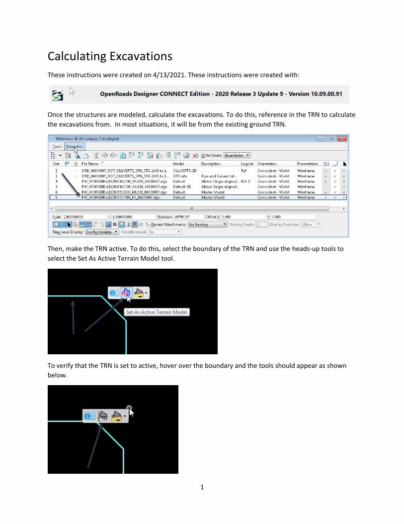
Once the structures are modeled, calculate the excavations. To do this, reference in the TRN to calculate the excavations from. In most situations, it will be from the existing ground TRN.
Then, make the TRN active. To do this, select the boundary of the TRN and use the heads-up tools to select the Set As Active Terrain Model tool.
To verify that the TRN is set to active, hover over the boundary and the tools should appear as shown below.

2
Once the TRN is set to active, then a profile needs to be applied to the conduit before the excavation template can be pushed. To do this, select the structure and select the Open Profile Model tool.
It will prompt to Select or Open View. For this example, use View 8.
3
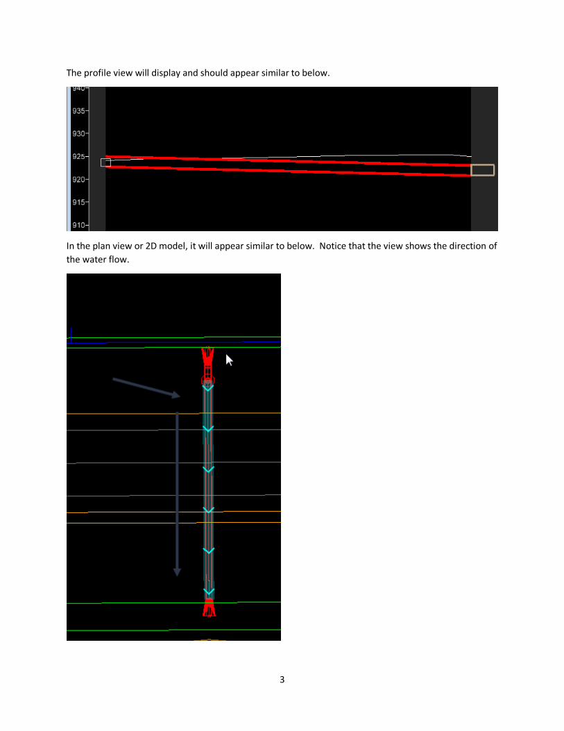
The profile view will display and should appear similar to below.
In the plan view or 2D model, it will appear similar to below. Notice that the view shows the direction of the water flow.

4
Once the profile has been applied to the conduit, the excavation can be calculated. To do this, unselect the conduit, then select it again to bring up the heads-up tools. But this time, select the Properties tool.
In the Properties, under the Trench field select Yes.
5
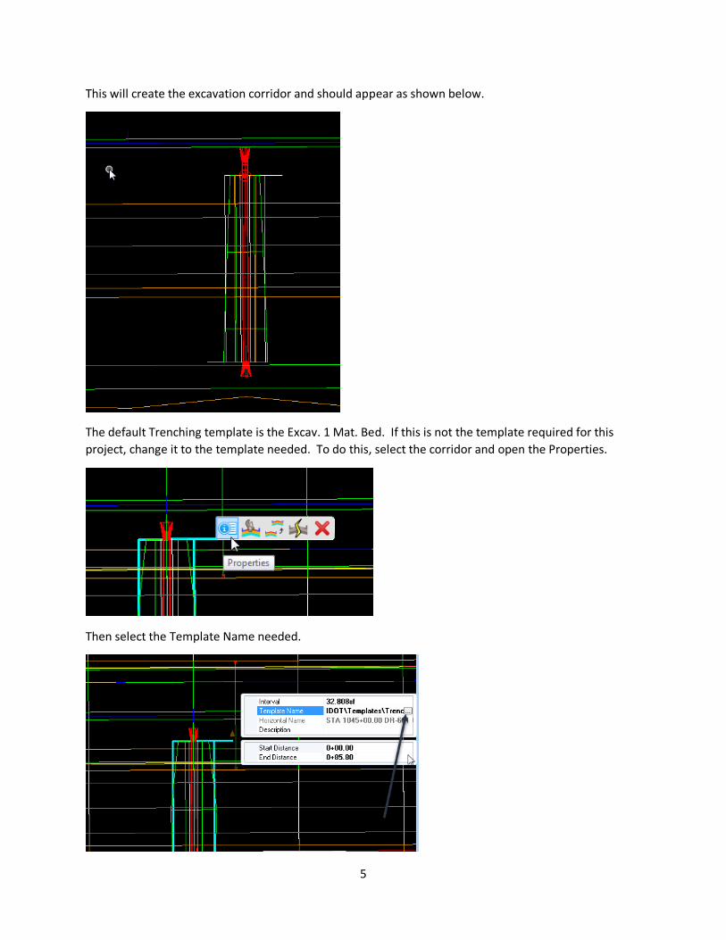
This will create the excavation corridor and should appear as shown below.
The default Trenching template is the Excav. 1 Mat. Bed. If this is not the template required for this project, change it to the template needed. To do this, select the corridor and open the Properties.
Then select the Template Name needed.
6
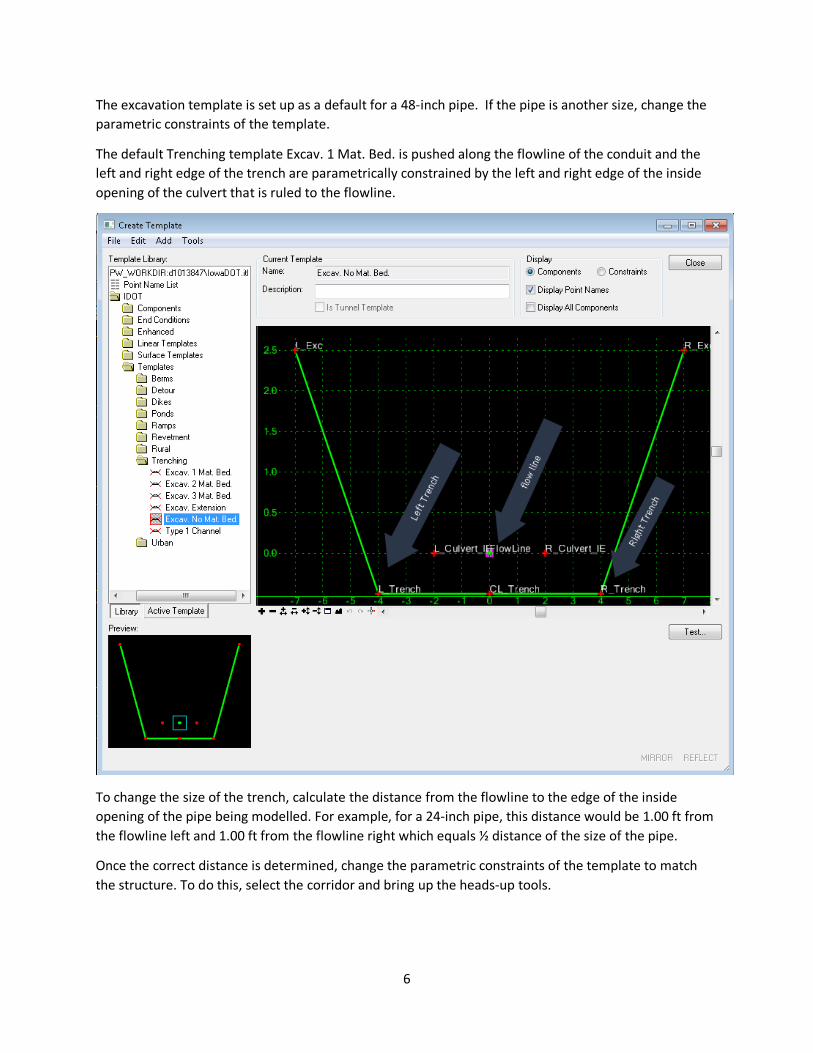
The excavation template is set up as a default for a 48-inch pipe. If the pipe is another size, change the parametric constraints of the template.
The default Trenching template Excav. 1 Mat. Bed. is pushed along the flowline of the conduit and the left and right edge of the trench are parametrically constrained by the left and right edge of the inside opening of the culvert that is ruled to the flowline.
To change the size of the trench, calculate the distance from the flowline to the edge of the inside opening of the pipe being modelled. For example, for a 24-inch pipe, this distance would be 1.00 ft from the flowline left and 1.00 ft from the flowline right which equals ½ distance of the size of the pipe.
Once the correct distance is determined, change the parametric constraints of the template to match the structure. To do this, select the corridor and bring up the heads-up tools.
7
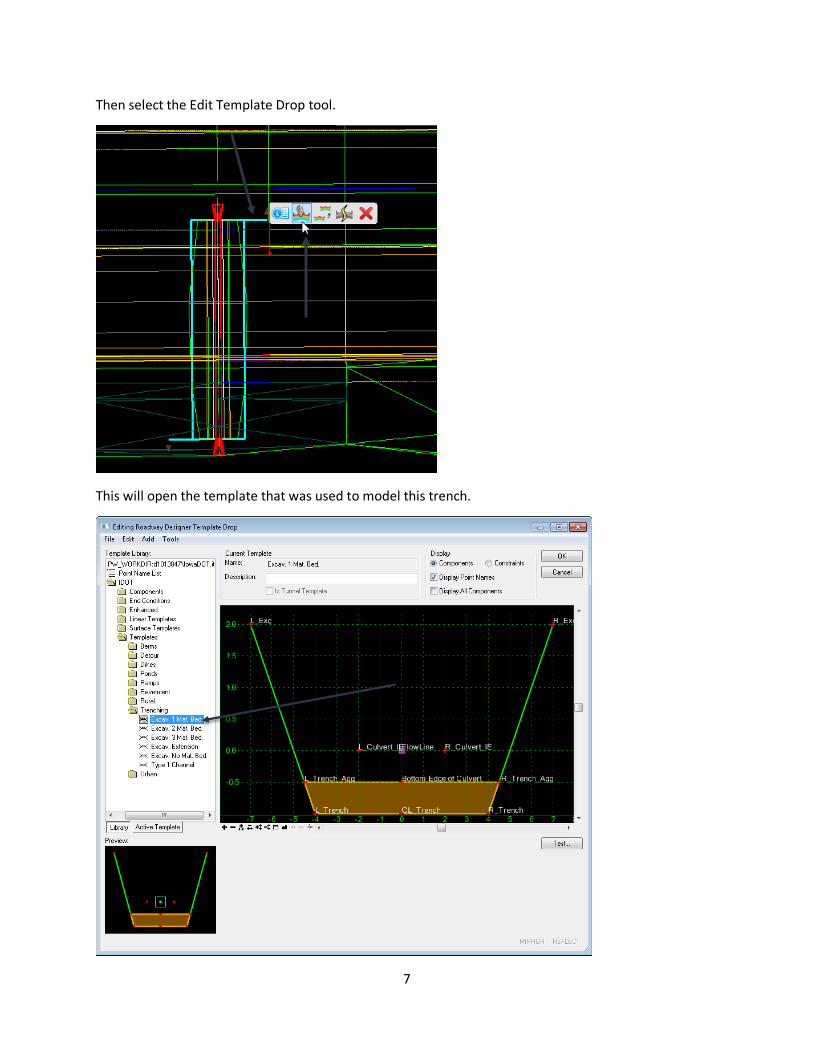
Then select the Edit Template Drop tool.
This will open the template that was used to model this trench.

8
To change the parametric constraints on the L_Culvert_IE or R_Culvert_IE points on the template, double click on the point in the template. It will open the constraints on that point. For this example, it will be a 24 inch pipe, so it should appear as shown below.
Once the constraint value is changed to -1.00 for the left-side, click on Apply then Close buttons. Then repeat the same operation on the other side. Note that the right-side constraint value will +1.00.
9
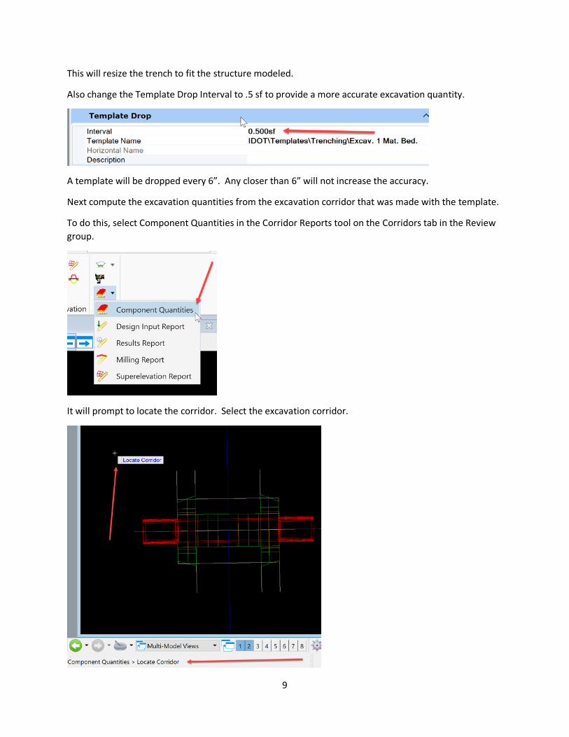
This will resize the trench to fit the structure modeled.
Also change the Template Drop Interval to .5 sf to provide a more accurate excavation quantity.
A template will be dropped every 6”. Any closer than 6” will not increase the accuracy.
Next compute the excavation quantities from the excavation corridor that was made with the template.
To do this, select Component Quantities in the Corridor Reports tool on the Corridors tab in the Review group.
It will prompt to locate the corridor. Select the excavation corridor.
10
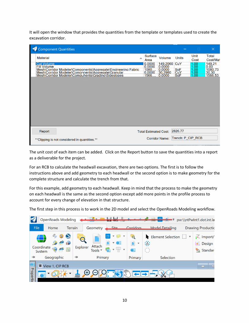
It will open the window that provides the quantities from the template or templates used to create the excavation corridor.
The unit cost of each item can be added. Click on the Report button to save the quantities into a report as a deliverable for the project.
For an RCB to calculate the headwall excavation, there are two options. The first is to follow the instructions above and add geometry to each headwall or the second option is to make geometry for the complete structure and calculate the trench from that.
For this example, add geometry to each headwall. Keep in mind that the process to make the geometry on each headwall is the same as the second option except add more points in the profile process to account for every change of elevation in that structure.
The first step in this process is to work in the 2D model and select the OpenRoads Modeling workflow.
11
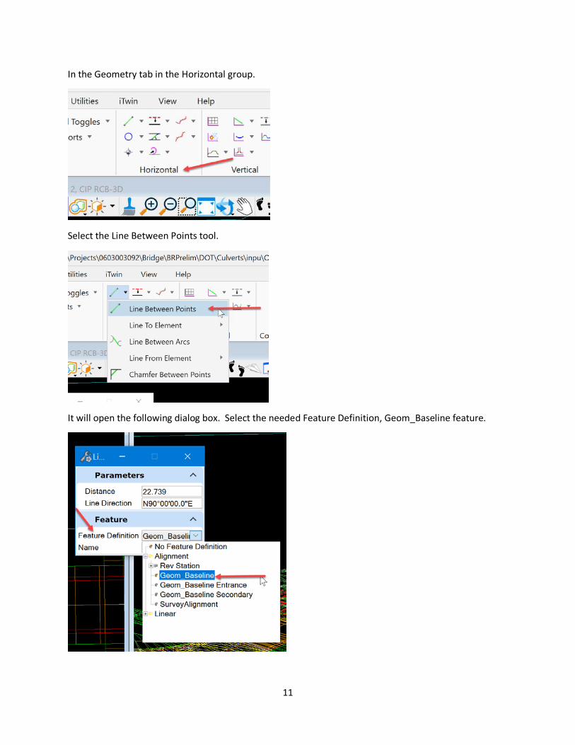
In the Geometry tab in the Horizontal group.
Select the Line Between Points tool.
It will open the following dialog box. Select the needed Feature Definition, Geom_Baseline feature.
12
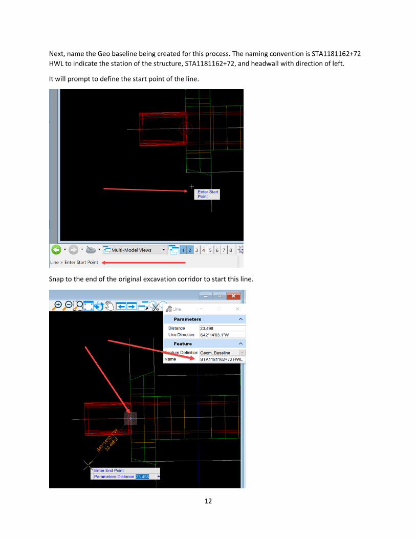
Next, name the Geo baseline being created for this process. The naming convention is STA1181162+72 HWL to indicate the station of the structure, STA1181162+72, and headwall with direction of left.
It will prompt to define the start point of the line.
Snap to the end of the original excavation corridor to start this line.
13
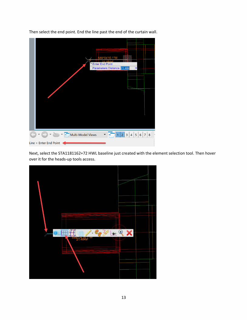
Then select the end point. End the line past the end of the curtain wall.
Next, select the STA1181162+72 HWL baseline just created with the element selection tool. Then hover over it for the heads-up tools access.

14
Next, select the Open Profile Model tool and then select a view to open it in.
For this example, select View 8.
Once the view is opened, data point in the view. The additional profile will display and appear similar to below.
15
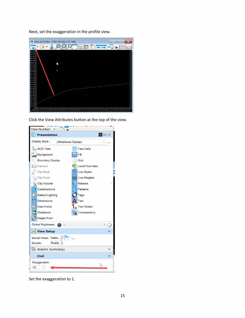
Next, set the exaggeration in the profile view.
Click the View Attributes button at the top of the view.
Set the exaggeration to 1.
16
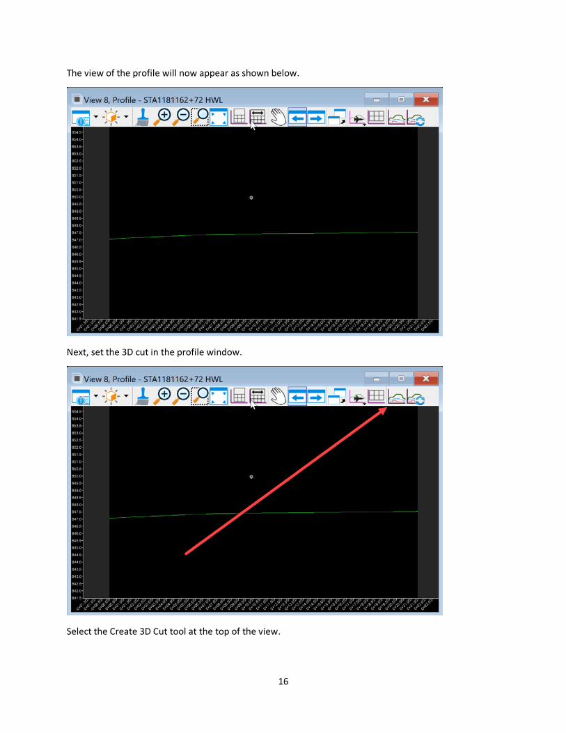
The view of the profile will now appear as shown below.
Next, set the 3D cut in the profile window.
Select the Create 3D Cut tool at the top of the view.
17
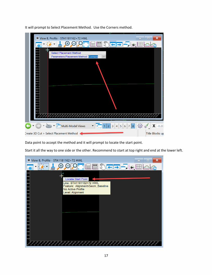
It will prompt to Select Placement Method. Use the Corners method.
Data point to accept the method and it will prompt to locate the start point.
Start it all the way to one side or the other. Recommend to start at top right and end at the lower left.

18
After the data point, a box will start drawing in the view to make the 3D cut.
Data point the end point to complete the 3D cut. It will appear as shown below.
Next, set the profile on the STA1181162+72 HWL baseline that was created.
19
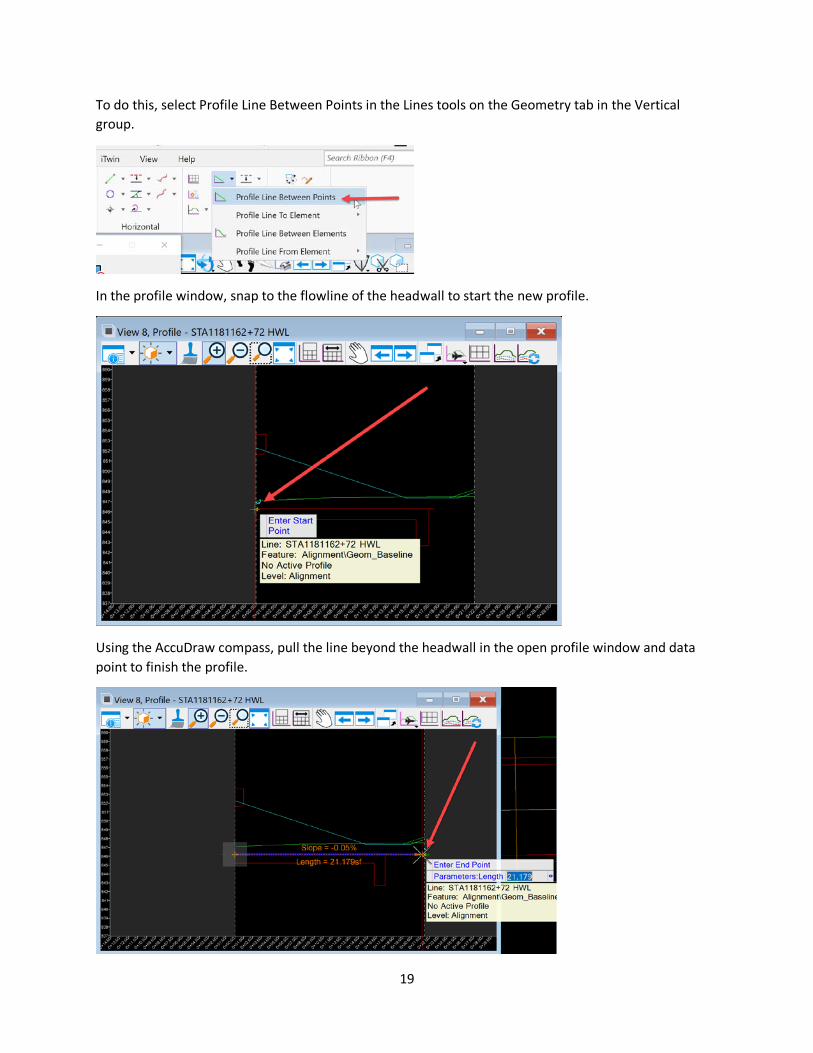
To do this, select Profile Line Between Points in the Lines tools on the Geometry tab in the Vertical group.
In the profile window, snap to the flowline of the headwall to start the new profile.
Using the AccuDraw compass, pull the line beyond the headwall in the open profile window and data point to finish the profile.
20
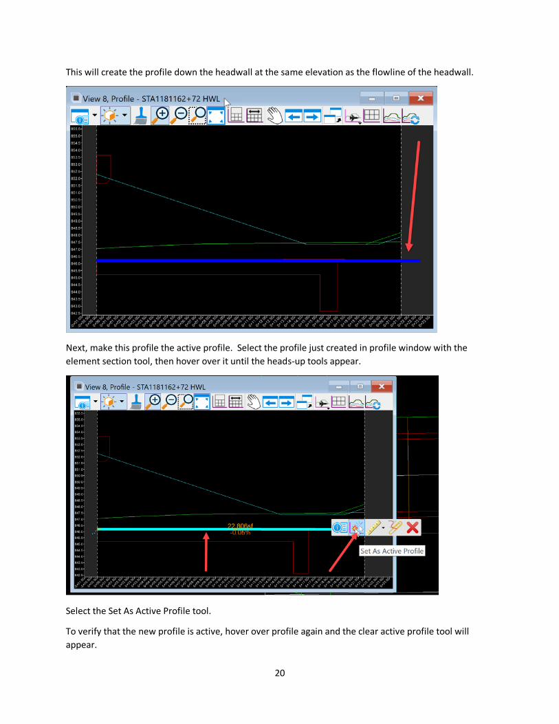
This will create the profile down the headwall at the same elevation as the flowline of the headwall.
Next, make this profile the active profile. Select the profile just created in profile window with the element section tool, then hover over it until the heads-up tools appear.
Select the Set As Active Profile tool.
To verify that the new profile is active, hover over profile again and the clear active profile tool will appear.
21
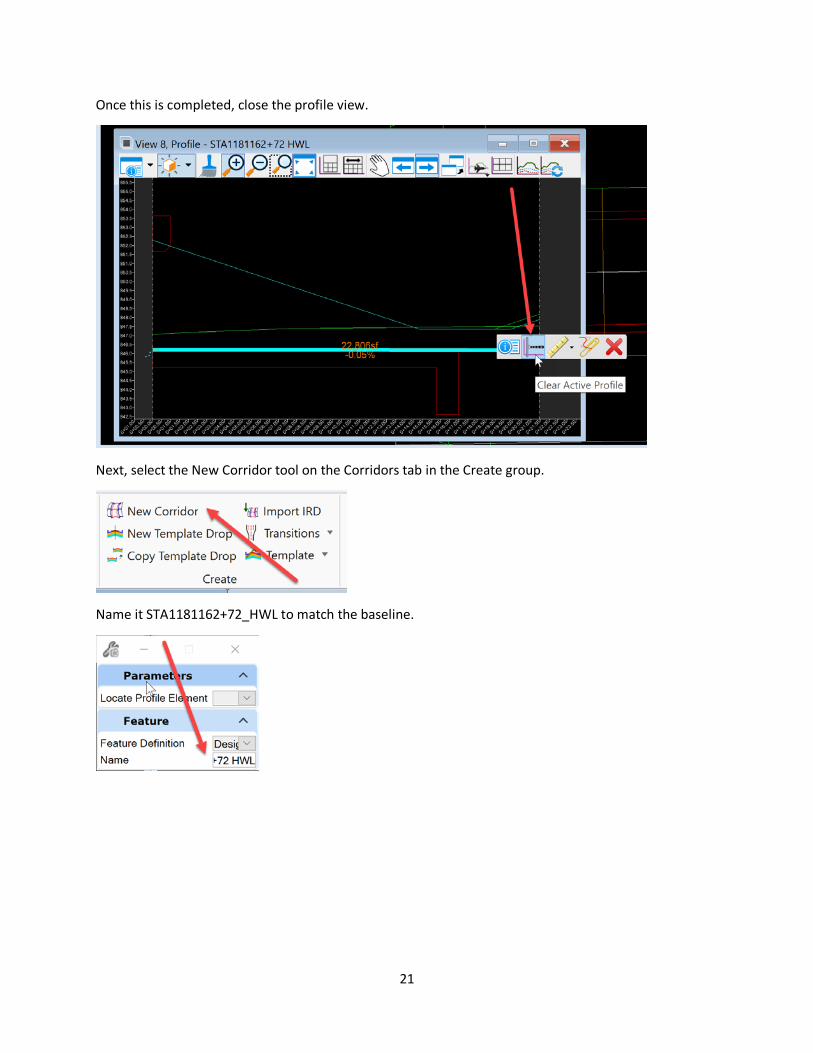
Once this is completed, close the profile view.
Next, select the New Corridor tool on the Corridors tab in the Create group.
Name it STA1181162+72_HWL to match the baseline.
22
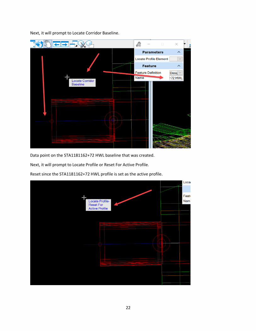
Next, it will prompt to Locate Corridor Baseline.
Data point on the STA1181162+72 HWL baseline that was created.
Next, it will prompt to Locate Profile or Reset For Active Profile.
Reset since the STA1181162+72 HWL profile is set as the active profile.
23
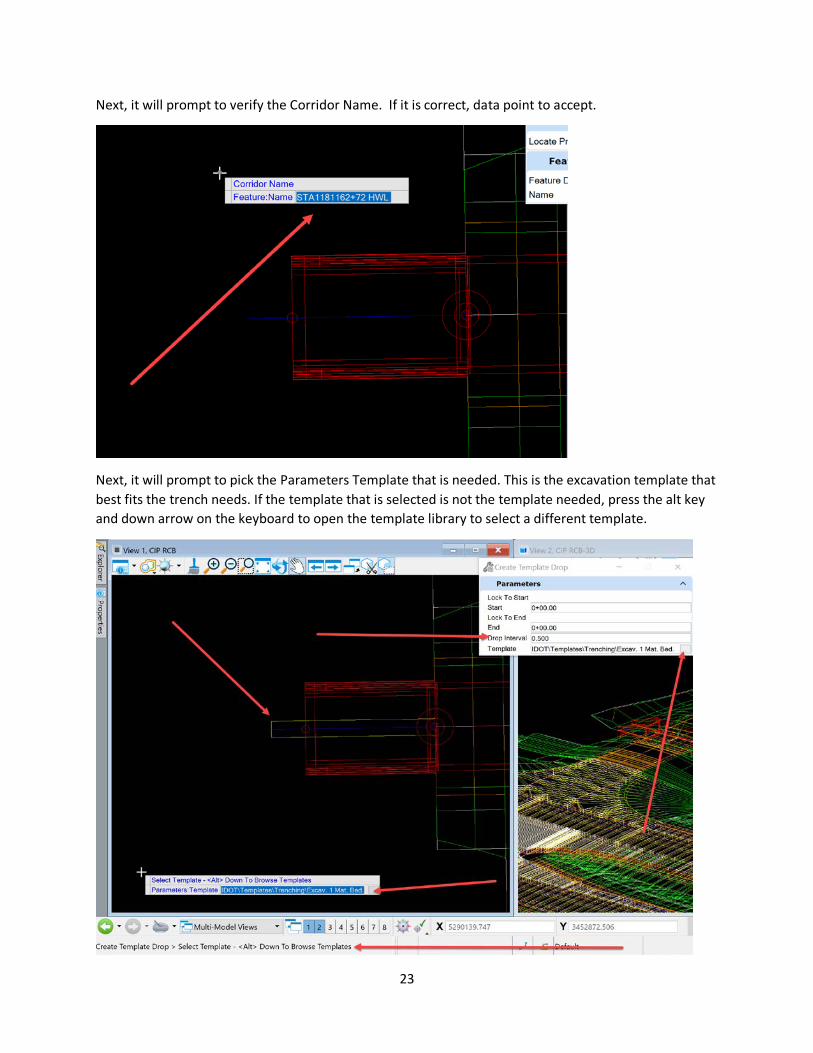
Next, it will prompt to verify the Corridor Name. If it is correct, data point to accept.
Next, it will prompt to pick the Parameters Template that is needed. This is the excavation template that best fits the trench needs. If the template that is selected is not the template needed, press the alt key and down arrow on the keyboard to open the template library to select a different template.

24
Once the template is selected, then data point to accept.
Next, it will prompt for a start station. Push the alt key on the keyboard to lock it to the beginning. Data point to accept.
Next, it will prompt for an end station. Push the alt key on the keyboard to lock it to the end station. Data point to accept.
25
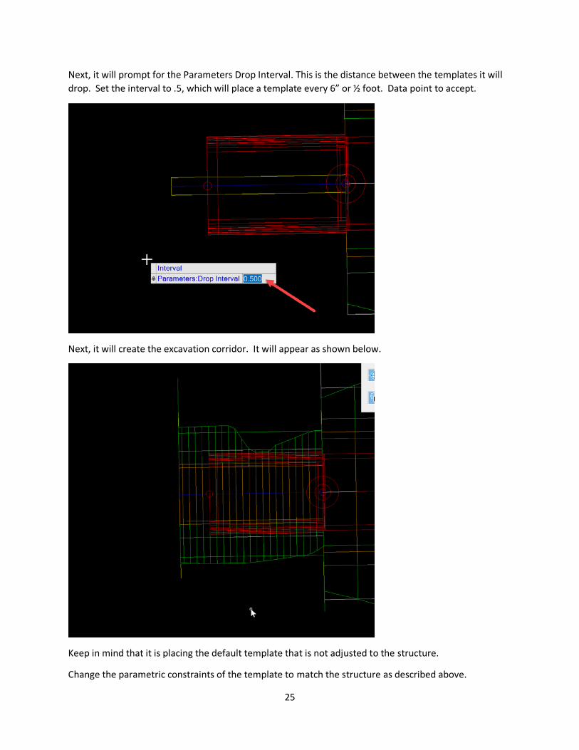
Next, it will prompt for the Parameters Drop Interval. This is the distance between the templates it will drop. Set the interval to .5, which will place a template every 6” or ½ foot. Data point to accept.
Next, it will create the excavation corridor. It will appear as shown below.
Keep in mind that it is placing the default template that is not adjusted to the structure.
Change the parametric constraints of the template to match the structure as described above.