calculation package for gcs maxspan plus thin-film system
TRANSCRIPT

Calculation Package for GCS MaxSpan Plus Thin-Film System (Mid Row Mids)
Project:
Address:
Update:
Dsun Ellis
140 Dodge Rd, Ithaca, NY 14850 10/3/2018 By: SC
General InformationSetup Portrait
Tilt 20 degree
Clearance 36 in
Panel Length 78.50 in
Panel Width 39.37 in
Panel Weight 50.7 lbs
Space between Panels N-S 0.5 in
Space between Panels E-W 0.5 in
Mounting Type Bottom
Number of Panels Up 2 #
Number of Purlins 4 #
Rail Spacing 2 ft (O.C.)
No. of Panels Supported per Span 13 #
No. of Panel Widths per Span 6.50 #
No. of Panel Widths per Overhang 1.25 #
Purlin Span Length 21.60 ft
Post Adjustment Zone Length 6 in
Loading Code ASCE7-10
Occupancy Category I
Exposure Category C
Seismic Site Class D
Assumed Load Bearing Capacity of Soil 1 ksf
Dead Load: 3.2 psf
Ground Snow Load (Pg) 45 psf
Basic Wind Speed 105 mph
Hurricane Status Not Prone
Seismic Design Values
Ss 0.126 g
S1 0.056 g
Fa 1.6
Fv 2.4
SDS 0.134 g
SD1 0.090 g
Page 1

1. Loading Calculations
1.1 Snow Load Snow load is calculated per ASCE7
Pg (psf) 45.00
Ce 0.90 Per Table 7-2.
Ct 1.20 Per Table 7-3.
Is 0.80 Per Table 7-4.
Cs 0.91 Per Figure 7-2c.
According to equation (7-1) and (7-2)
Ps=Cs*Pf = Cs*(0.7Ce*Ct*Is*Pg) Ps = 24.74
1.2 Wind Load Wind pressure is calculated per ASCE7
V (mph) 105.00
Kd 0.85 Per Table 26.6-1
Kz 1.00 Per Wind Tunnel Test Report
Kzt 1.00 Per Section 26.8
Iw 1.00 Wind Importance Factor equals unity for ASCE7-10
According to Equation (27.3-1)
qh = 0.00256*Kd*Kz*Kzt*(V^2)*I qh = 23.99
According to equation (27.4-3)
P=qhGCN
The results of wind load factors including normal and overt urning moments provided by CPP are located in the calculation sheets. The results are given for two opposite directions of wind which causes upward and downward wind forces calculated based on worst case design wind loads. GCN is the normal force factor, GC-My is the moment at the base of the post. The factor of safety is calculated based on the worst case scenario, when the dead load and full wind loads are present. These factors are used to generate all wind load components for the following calculations.
Page 2

NOTE: The gust coefficients shown above are from wind tunnel testing performed in accordance with Section 6.6 of ASCE7-05 and Chapter 31 of
ASCE7-10
Page 3
1.3 Load Combinations:
Basic load combinations are per ASCE7-10 and ASD design method.
1 D
2 D + S
3 D + 0.60W
4 D + 0.75S + 0.45W
5 0.6D +/- 0.60W
6 D + 0.7E
1.4 Safety FactorsΩc Ωb Ωv SFFDN
Safety Factor 1.5 1.5 1.5 1.5
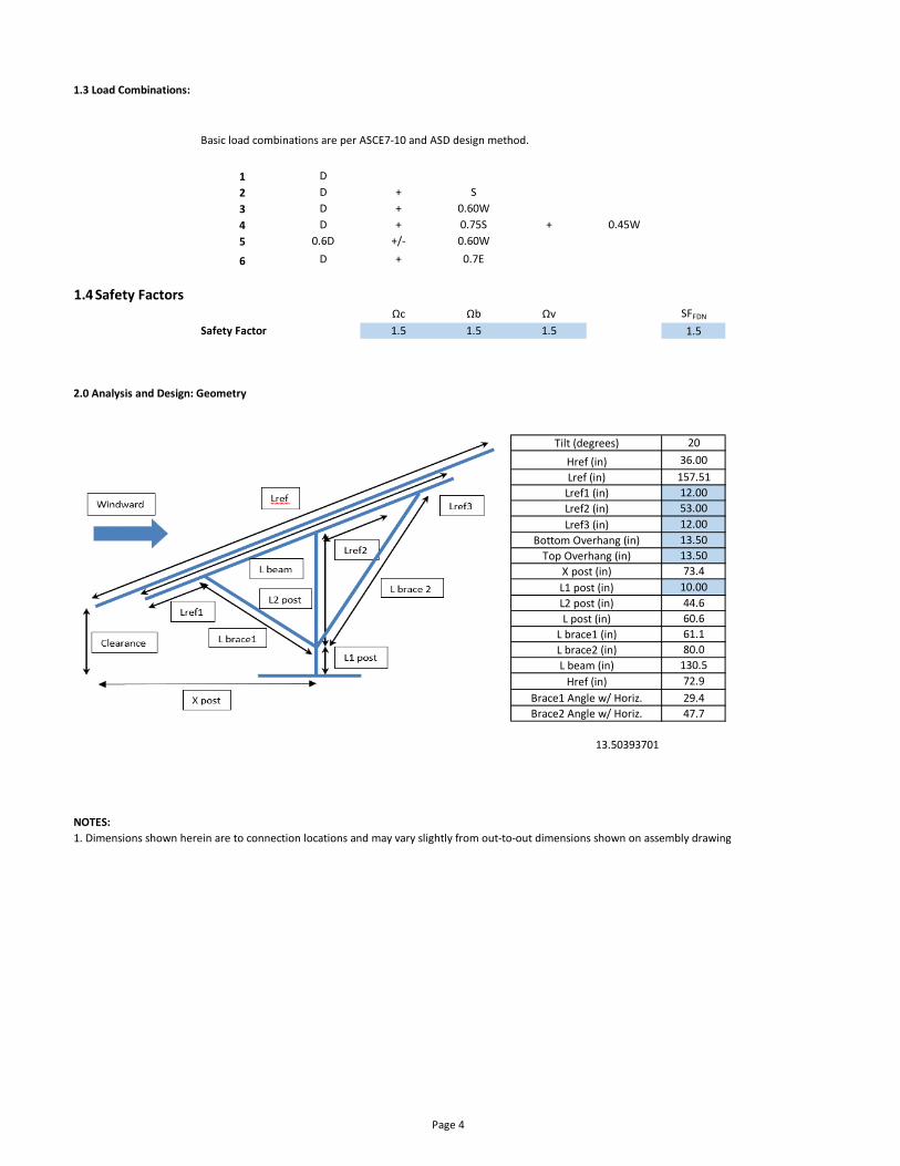
2.0 Analysis and Design: Geometry
20
36.00
157.51
12.00
53.00
12.00
13.50
13.50
73.4
10.00
44.6
60.6
61.1
80.0
130.5
72.9
29.4
47.7
13.50393701
NOTES:
Lref3 (in)
Tilt (degrees)
X post (in)
L1 post (in)
L2 post (in)
L post (in)
L brace1 (in)
L brace2 (in)
Brace1 Angle w/ Horiz.
Brace2 Angle w/ Horiz.
Lref (in)
Bottom Overhang (in)
Top Overhang (in)
Lref1 (in)
Lref2 (in)
Href (in)
L beam (in)
Href (in)
1. Dimensions shown herein are to connection locations and may vary slightly from out-to-out dimensions shown on assembly drawing
Page 4
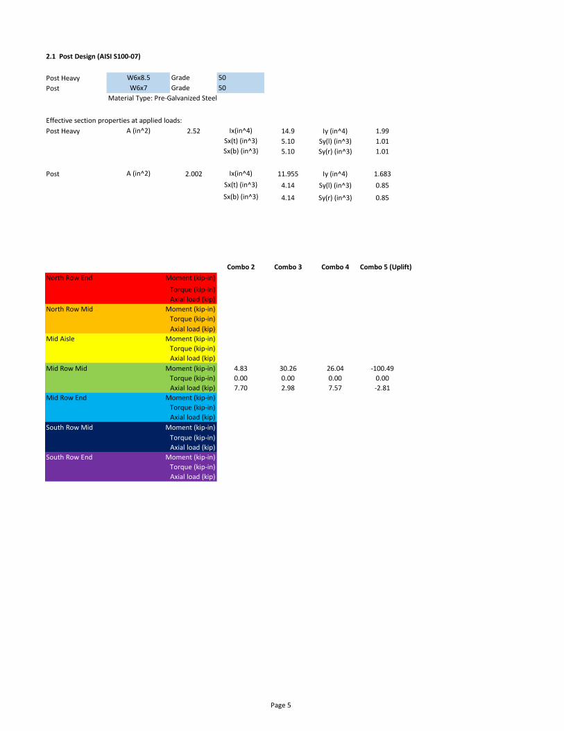
2.1 Post Design (AISI S100-07)
Post Heavy W6x8.5 Grade 50
Post W6x7 Grade 50
Material Type: Pre-Galvanized Steel
Effective section properties at applied loads:
Post Heavy A (in^2) 2.52 Ix(in^4) 14.9 Iy (in^4) 1.99
Sx(t) (in^3) 5.10 Sy(l) (in^3) 1.01
Sx(b) (in^3) 5.10 Sy(r) (in^3) 1.01
Post A (in^2) 2.002 Ix(in^4) 11.955 Iy (in^4) 1.683
Sx(t) (in^3) 4.14 Sy(l) (in^3) 0.85
Sx(b) (in^3) 4.14 Sy(r) (in^3) 0.85
Combo 2 Combo 3 Combo 4 Combo 5 (Uplift)
North Row End Moment (kip-in) 4.83 57.77 46.67 -182.69
Torque (kip-in) 0.00 0.00 0.00 0.00
Axial load (kip) 7.70 5.41 9.39 -4.95
North Row Mid Moment (kip-in) 4.83 51.74 42.15 -149.51
Torque (kip-in) 0.00 0.00 0.00 0.00
Axial load (kip) 7.70 3.38 7.87 -4.54
Mid Aisle Moment (kip-in) 4.83 46.01 37.85 -114.91
Torque (kip-in) 0.00 0.00 0.00 0.00
Axial load (kip) 7.70 4.61 8.79 -2.58
Mid Row Mid Moment (kip-in) 4.83 30.26 26.04 -100.49
Torque (kip-in) 0.00 0.00 0.00 0.00
Axial load (kip) 7.70 2.98 7.57 -2.81
Mid Row End Moment (kip-in) 4.83 49.26 40.29 -144.70
Torque (kip-in) 0.00 0.00 0.00 0.00
Axial load (kip) 7.70 4.46 8.68 -4.46
South Row Mid Moment (kip-in) 4.83 30.88 26.51 -148.01
Torque (kip-in) 0.00 0.00 0.00 0.00
Axial load (kip) 7.70 4.10 8.41 -3.33
South Row End Moment (kip-in) 4.83 53.93 43.79 -171.81
Torque (kip-in) 0.00 0.00 0.00 0.00
Axial load (kip) 7.70 4.55 8.75 -5.57
Page 5
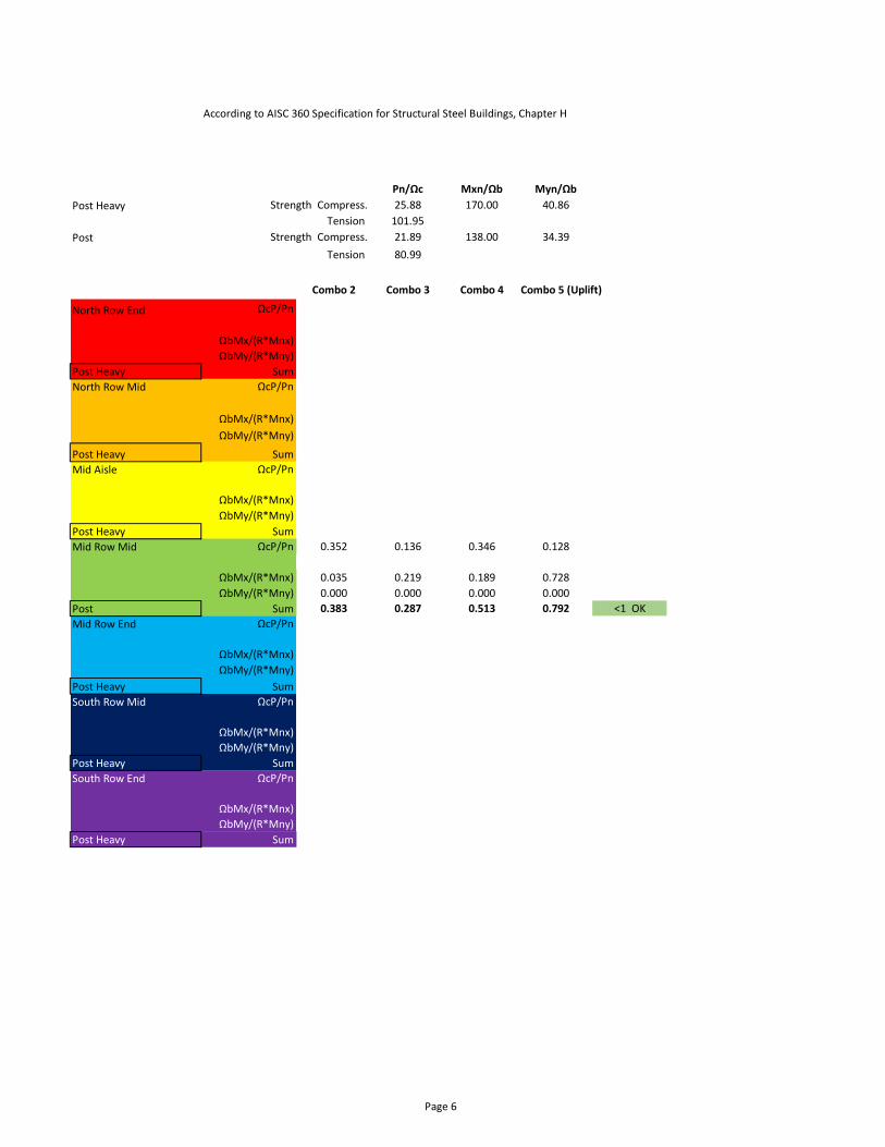
Pn/Ωc Mxn/Ωb Myn/Ωb
Post Heavy Strength Compress. 25.88 170.00 40.86
Tension 101.95
Post Strength Compress. 21.89 138.00 34.39
Tension 80.99
Combo 2 Combo 3 Combo 4 Combo 5 (Uplift)
North Row End ΩcP/Pn 0.298 0.209 0.363 0.191
1.00 1.00 1.00 1.00
ΩbMx/(R*Mnx) 0.028 0.340 0.275 1.075
ΩbMy/(R*Mny) 0.000 0.000 0.000 0.000
Post Heavy Sum 0.323 0.511 0.607 1.170 >1 NOT OK
North Row Mid ΩcP/Pn 0.298 0.131 0.304 0.175
1.00 1.00 1.00 1.00
ΩbMx/(R*Mnx) 0.028 0.304 0.248 0.879
ΩbMy/(R*Mny) 0.000 0.000 0.000 0.000
Post Heavy Sum 0.323 0.370 0.524 0.967 <1 OK
Mid Aisle ΩcP/Pn 0.298 0.178 0.340 0.100
1.00 1.00 1.00 1.00
ΩbMx/(R*Mnx) 0.028 0.271 0.223 0.676
ΩbMy/(R*Mny) 0.000 0.000 0.000 0.000
Post Heavy Sum 0.323 0.360 0.538 0.726 <1 OK
Mid Row Mid ΩcP/Pn 0.352 0.136 0.346 0.128
1.00 1.00 1.00 1.00
ΩbMx/(R*Mnx) 0.035 0.219 0.189 0.728
ΩbMy/(R*Mny) 0.000 0.000 0.000 0.000
Post Sum 0.383 0.287 0.513 0.792 <1 OK
Mid Row End ΩcP/Pn 0.298 0.172 0.335 0.172
1.00 1.00 1.00 1.00
ΩbMx/(R*Mnx) 0.028 0.290 0.237 0.851
ΩbMy/(R*Mny) 0.000 0.000 0.000 0.000
Post Heavy Sum 0.323 0.376 0.546 0.937 <1 OK
South Row Mid ΩcP/Pn 0.298 0.158 0.325 0.128
1.00 1.00 1.00 1.00
ΩbMx/(R*Mnx) 0.028 0.182 0.156 0.871
ΩbMy/(R*Mny) 0.000 0.000 0.000 0.000
Post Heavy Sum 0.323 0.261 0.463 0.935 <1 OK
South Row End ΩcP/Pn 0.298 0.176 0.338 0.215
1.00 1.00 1.00 1.00
ΩbMx/(R*Mnx) 0.028 0.317 0.258 1.011
ΩbMy/(R*Mny) 0.000 0.000 0.000 0.000
Post Heavy Sum >1 NOT OK
According to AISC 360 Specification for Structural Steel Buildings, Chapter H
Page 6

2.2 Brace Design
Shape Grade 80 ksi
Material Type:Pre-galvanized Steel
Effective section properties at applied loads
Ae (in^2) 0.68 Ixe (in^4) 2.26 Iye (in^4) 0.44
Sxe(t) (in^4) 1.01 Sye(l) (in^4) 0.67
Sxe(b) (in^4) 1.01 Sye(r) (in^4) 0.23
Loads below are for governing Brace (North or South)
kip kip-in kip-in
Axial force (kip) Combo 2 Combo 3 Combo 4 Combo 5 (Uplift) P Mx My
North Row End 0.02 0.66 0.51 2.51 2.51 0 2.01
North Row Mid 0.02 0.59 0.46 2.58 2.58 0 2.06
Mid Aisle 0.02 0.50 0.39 1.34 1.34 0 1.07
Mid Row Mid 0.02 0.36 0.28 1.66 1.66 0 1.33
Mid Row End 0.02 0.52 0.40 2.00 2.00 0 1.60
South Row Mid 0.02 0.43 0.34 1.98 1.98 0 1.59
South Row End 0.01 -0.33 -0.24 1.46 1.46 0 1.17
Pn/Ωc Mxn/Ωb Myn/Ωb
Strength 13.19 41.91 9.53
ΩcP/Pn ΩbMx/Mnx ΩbMy/Mny Sum
North Row End 0.190 0.000 0.210 0.400 <1 OK
North Row Mid 0.195 0.000 0.216 0.412 <1 OK
Mid Aisle 0.101 0.000 0.112 0.214 <1 OK
Mid Row Mid 0.126 0.000 0.139 0.265 <1 OK
Mid Row End 0.152 0.000 0.168 0.319 <1 OK
South Row Mid 0.150 0.000 0.166 0.316 <1 OK
South Row End 0.111 0.000 0.123 0.233 <1 OK
According to North American Specification for the Design of Cold-Formed Steel Structural Members
(2007 Edition), Equation C5.2.1-1-C5.2.1.3.As ΩbP/Pn>0.15, equation C5.2.1-2 should be adopted.
Cee 4.5x2.6 - 14 Ga Facing E-W
Page 7
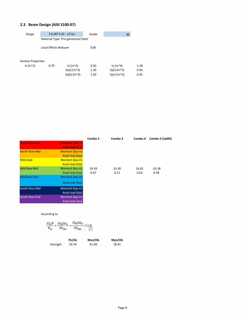
2.3 Beam Design (AISI S100-07)
Shape Grade 80
Material Type: Pre-galvanized Steel
Local Effects Reducer 0.85
Section Properties
A (in^2) 0.79 Ix (in^4) 4.50 Iy (in^4) 1.28
Sx(t) (in^3) 1.50 Sy(l) (in^3) 0.45
Sx(b) (in^3) 1.50 Sy(r) (in^3) 0.45
Combo 2 Combo 3 Combo 4 Combo 5 (Uplift)
North Row End Moment (kip-in) 24.59 19.17 31.40 -18.11
Axial load (kip) 0.67 0.33 0.70 0.94
North Row Mid Moment (kip-in) 24.59 11.84 25.91 -16.64
Axial load (kip) 0.67 0.31 0.69 0.97
Mid Aisle Moment (kip-in) 24.59 16.28 29.24 -9.56
Axial load (kip) 0.67 0.27 0.66 0.48
Mid Row Mid Moment (kip-in) 24.59 10.38 24.81 -10.38
Axial load (kip) 0.67 0.21 0.62 0.58
Mid Row End Moment (kip-in) 24.59 15.74 28.83 -16.36
Axial load (kip) 0.67 0.27 0.66 0.71
South Row Mid Moment (kip-in) 24.59 14.44 27.86 -12.25
Axial load (kip) 0.67 0.24 0.64 0.74
South Row End Moment (kip-in) 24.59 16.09 29.09 -20.35
Axial load (kip) 0.67 0.29 0.68 0.90
According to
Pn/Ωc Mxn/Ωb Myn/Ωb
Strength 32.54 61.69 18.41
Z 6.00*2.92 - 14 Ga
6.5"
Page 8
Combo 2 Combo 3 Combo 4 Combo 5 (Uplift)
North Row End ΩcP/Pn 0.021 0.010 0.022 0.029
ΩbMx/Mnx 0.399 0.311 0.509 0.294
ΩbMy/Mny 0.000 0.000 0.000 0.000
Sum 0.419 0.321 0.531 0.323 <1 OK
North Row Mid ΩcP/Pn 0.021 0.009 0.021 0.030
ΩbMx/Mnx 0.399 0.192 0.420 0.270
ΩbMy/Mny 0.000 0.000 0.000 0.000
Sum 0.419 0.201 0.441 0.300 <1 OK
Mid Aisle ΩcP/Pn 0.021 0.008 0.020 0.015
ΩbMx/Mnx 0.399 0.264 0.474 0.155
ΩbMy/Mny 0.000 0.000 0.000 0.000
Sum 0.419 0.272 0.494 0.170 <1 OK
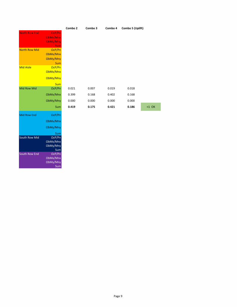
Mid Row Mid ΩcP/Pn 0.021 0.007 0.019 0.018
ΩbMx/Mnx 0.399 0.168 0.402 0.168
ΩbMy/Mny 0.000 0.000 0.000 0.000
Sum 0.419 0.175 0.421 0.186 <1 OK
Mid Row End ΩcP/Pn 0.021 0.008 0.020 0.022
ΩbMx/Mnx 0.399 0.255 0.467 0.265
ΩbMy/Mny 0.000 0.000 0.000 0.000
Sum 0.419 0.264 0.488 0.287 <1 OK
South Row Mid ΩcP/Pn 0.021 0.007 0.020 0.023
ΩbMx/Mnx 0.399 0.234 0.452 0.199
ΩbMy/Mny 0.000 0.000 0.000 0.000
Sum 0.419 0.241 0.471 0.221 <1 OK
South Row End ΩcP/Pn 0.021 0.009 0.021 0.028
ΩbMx/Mnx 0.399 0.261 0.472 0.330
ΩbMy/Mny 0.000 0.000 0.000 0.000
Sum 0.419 0.270 0.492 0.358 <1 OK
Page 9

2.4 Purlin Design
Grade Gauge
Heavy Grade 80 Gauge 16 - 6x2.92
Light Grade 80 Gauge 16 - 6x2.92
Effective Properties
Heavy Grade A (in^2) 0.686 Ix (in^4) 3.881 Iy (in^4) 1.06
Sx(t) (in^3) 1.294 Sy(l) (in^3) 0.363
Sx(b) (in^3) 1.294 Sy(r) (in^3) 0.363
Light Grade A (in^2) 0.686 Ix (in^4) 3.881 Iy (in^4) 1.06
Sx(t) (in^3) 1.294 Sy(l) (in^3) 0.363
Sx(b) (in^3) 1.294 Sy(r) (in^3) 0.363
Combo 2 Combo 3 Combo 4 Combo 5 (Uplift)
North Row End moment major (kip-in) 58.98 45.97 75.31 -43.44
moment minor (kip-in) 5.26 0.61 4.10 0.36
North Row Mid moment major (kip-in) 50.13 24.14 52.81 -33.91
moment minor (kip-in) 4.47 0.52 3.48 0.31
Mid Aisle moment major (kip-in) 58.98 39.05 70.12 -22.93
moment minor (kip-in) 5.26 0.61 4.10 0.36
Mid Row Mid moment major (kip-in) 40.69 17.18 41.06 -17.17
moment minor (kip-in) 4.47 0.52 3.48 0.52
Mid Row End moment major (kip-in) 58.98 37.75 69.15 -39.24
moment minor (kip-in) 5.26 0.61 4.10 0.61
South Row Mid moment major (kip-in) 50.13 29.43 56.79 -24.97
moment minor (kip-in) 4.47 0.52 3.48 0.31
South Row End moment major (kip-in) 58.98 38.59 69.78 -48.80
moment minor (kip-in) 5.26 0.61 4.10 0.36
Buckling Check (Per Equation C3.1.2.1-15):
Fc(x) (ksi) Fc(y) (ksi) Fc(x) (ksi) Fc(y) (ksi)
Heavy Grade Strength 66.80 81.08 44.46 75.43
Light Grade Strength 66.80 81.08 44.46 75.43
Mx/Ωb My/Ωb Mx/Ωb My/Ωb
kip-in kip-in kip-in kip-in
Heavy Grade Strength 54.87 18.69 36.52 17.39
Light Grade Strength 54.87 18.69 36.52 17.39
Continuous Spans End Spans
6.00"
2.92"
Page 10

Combo 2 Combo 3 Combo 4 Combo 5 (Uplift)
North Row End ΩbMx/Mnx 1.615 1.259 2.062 1.190
ΩbMy/Mny 0.303 0.035 0.236 0.021
Light Grade Sum 1.918 1.294 2.298 1.211 >1 NOT OK
North Row Mid ΩbMx/Mnx 0.914 0.440 0.962 0.618
ΩbMy/Mny 0.239 0.028 0.186 0.017
Light Grade Sum 1.153 0.467 1.149 0.635 >1 NOT OK
Mid Aisle ΩbMx/Mnx 1.615 1.069 1.920 0.628
ΩbMy/Mny 0.303 0.035 0.236 0.021
Light Grade Sum 1.918 1.104 2.156 0.649 >1 NOT OK
Mid Row Mid ΩbMx/Mnx 0.742 0.313 0.748 0.313
ΩbMy/Mny 0.239 0.028 0.186 0.028
Light Grade Sum 0.981 0.341 0.935 0.341 <1 OK
Mid Row End ΩbMx/Mnx 1.615 1.034 1.894 1.075
ΩbMy/Mny 0.303 0.035 0.236 0.035
Light Grade Sum 1.918 1.069 2.129 1.109 >1 NOT OK
South Row Mid ΩbMx/Mnx 0.914 0.536 1.035 0.455
ΩbMy/Mny 0.239 0.028 0.186 0.017
Light Grade Sum 1.153 0.564 1.221 0.472 >1 NOT OK
South Row End ΩbMx/Mnx 1.615 1.057 1.911 1.336
ΩbMy/Mny 0.303 0.035 0.236 0.021
Light Grade Sum 1.918 1.092 2.147 1.357 >1 NOT OK
Deflection Check
Allowable deflection per panel manufacturer = L/ 100 (0.01mm/mm)
Max at midspan (in) 0.918 0.758 0.855 0.726 0.843 0.815 0.851
∆ / L 0.004 0.003 0.003 0.003 0.003 0.003 0.003
Check OK OK OK OK OK OK OK
Purlin Angle Check: OK
Note:
According to North American Specification for the Design of Cold-Formed Steel Structural Members (2007
Edition), Equation C5.2.1-1-C5.2.1.3
North Row Ends North Row Mid Mid Aisles Mid Row Mid Mid Row Ends South Row MidSouth Row
Ends
The Purlin analysis above accounts for the longest acceptable purlin length for this project. Some purlins supplied for this project may be
shorter than this length due to site geometry or to match the number of panels in a rack with a client requested string size. As the shorter
purlins will have less load applied to them and a shorter unbraced length, they have sufficient structural capacty to resist the applied loads.
Page 11

3. Seismic Forces
Seismic Design Values
Ss 0.126 g
S1 0.056 g
Fa 1.6
Fv 2.4
SDS 0.13 g
SD1 0.09 g
R 1.25 Per Table 12.2-1 For Steel Ordinary Cantilever Columns
Ie1
Per Table 1.5-2
W 3.22 psf
Cs 0.11 g Per Eq. 15.4-2
V0.35 psf Per Eq. 12.8-1
Seismic force is much lower than lateral wind loads calculated for analysis.
Wind load controls the design.
Page 12

4. Foundation
Vertical Loading
Gust Coefficient (GCN) 1.08 0.96 0.63 0.64 1.03 0.72 1.26
Wind Uplift Pressure (psf) 25.82 22.93 15.00 15.23 24.62 17.35 30.17
Wind Uplift Force (k) 4.06 3.61 2.36 2.40 3.87 2.73 4.75
Downward Force1 (k) 0.54 0.54 0.54 0.54 0.54 0.54 0.54
Max Net Uplift Force (Pull out
resistance) (k)5.28 4.60 2.73 2.79 5.00 3.29 6.31
Max Net Downward Force (k) 9.22 7.80 8.68 7.80 8.56 8.33 8.62
Lateral Loading
Max Net Lateral Force (Lateral
resistance) (k) 2.29 1.97 1.90 1.31 2.11 1.64 2.59
Note:
1. Downward force includes 0.6D load combination factor
2. Max Uplift and Lateral Foundation loads shown include safety factor
Mid Row Ends South Row Mid South Row Ends
North Row Ends North Row Mid Mid Aisles Mid Row Mid Mid Row Ends South Row Mid South Row Ends
North Row Ends North Row Mid Mid Aisles Mid Row Mid
Page 13