calibration of notches - cittumkur.org the steps 4 & 5 for 5 or 6 times by increasing the...
TRANSCRIPT

Fluid Mechanics and Hydraulic Machines Laboratory IV Semester, Civil
Department of Civil Engineering, C.I.T. Gubbi-572 216 1
CALIBRATION OF NOTCHES
A notch may be defined as an overflow opening provided in the side of a tank or a small channel such
that the liquid surface in the tank or channel is below the top edge of the Opening. Notches are usually
used in narrow channels in order to measure the small charges accurately.
Notches are classified according to the shape of the opening as rectangular notch, triangular notch (or
v-notch), trapezoidal notch, parabolic notch, stepped notch etc. Notches may also be classified
according to the effect of the nappe emerging from a notch, as a notch with end contractions and a
notch without end contractions or suppressed notch.
A Triangular notch may be further classified as 900 V-notch and 600 V-notch depending upon the
angle between the two sloping sides.
Cipolletti notch is a specific type of Trapezoidal notch, with side slopes of 1 horizontal to
4 vertical i.e. 142/ 02’.
The discharge equations for triangular, rectangular and trapezoidal (cipolletti) notches can be written
as:
1. Triangular notch;
)1.(2
tan215
825
eqgHCQ dactual
2. Rectangular notch (Suppressed):
)2.(23
223
eqLgHCQ dactual
where:
Cd is the coefficient of discharge.
H is the head over the notch.
L is the length of the notch at crest level.

Fluid Mechanics and Hydraulic Machines Laboratory IV Semester, Civil
Department of Civil Engineering, C.I.T. Gubbi-572 216 2
In general, the above equations can be written as:
)3.(eqKHQ Nactual
Where:
K is the constant for the given notch & N is the index.
The purpose of calibration of the notches is to find the constant K and the index N. In the laboratory it
is necessary to measure Qactual and the head over the notches H to calculate K and N.
After measuring Qactual and H, we have to draw a curve of Qactual v/s H. But this curve will be non
linear. Because of non linearity, interpolation or extrapolation of discharge Q for a given head H
becomes difficult. In order to overcome this difficulty the eq.(4) can be expressed in terms of
logarithmic functions as:
Log Q =N log H + log K Eq(4), Which represents a straight line.
The slope of the curve is
)5.(log
eqLogH
KLogQN
For H-1, log Q= log K, Which represents the interception of log Q v/s log H curve on y-axis.
If we express the above equation in terms of anti logarithm function, then
Q=K ……………..
From the above equation the value of C for the given notch can be found out.

Fluid Mechanics and Hydraulic Machines Laboratory IV Semester, Civil
Department of Civil Engineering, C.I.T. Gubbi-572 216 3
Experiment No. 1
Calibration of 90o V-Notch
Aim of the experiment: To determine the coefficient of discharge Cd, constant K & the index N for
the given notch.
Apparatus required: Hook gauge, a 90o V-notch, scale & a stop watch.
Experimental procedure:
1. Note down the least count of the hook gauge.2. Measure the dimensions of the measuring tank.3. Maintain the water level just at the sill of the notch and note down the no-flow head over the
notch (initial level of hook gauge) by using the hook gauge.4. By operating the control valve at the upstream side of the notch slowly increase the head over
the notch & when flow becomes steady note down the final reading of the hook gauge.5. Note down the time in seconds required to collect 5 cm of water, in the measuring tank6. Repeat the steps 4 & 5 for 5 or 6 times.7. Tabulate the readings as shown in the table.8. Draw a curve of Q v/s H on a log-log graph.9. Determine the value of Cd & N.
Specimen Calculations: For Trial No 1
Head over the notch (H) = Final hook gauge reading Initial hook gauge reading
H= ……cm.
Time taken for 5cm (h) rise of water in collecting tank, t = sec
sec/3mt
LxBxhQactual
Draw a graph of Q vs H on log-log graph.
From the graph the slope of the line, N =
Q= K, for H=1
Where, =90o
2
tan215
8 gCK d
2tan28
15q
KCd =
Conclusions:

Fluid Mechanics and Hydraulic Machines Laboratory IV Semester, Civil
Department of Civil Engineering, C.I.T. Gubbi-572 216 4
TABLE -1Calibration of 90o V-Notch
Dimensions of measuring tank: Length, L = cmBreadth, B = cmDepth of water collected =Least count of hook gauge = mm
SlNo
Head over 900 V-notchTime taken for 5
cm rise of water inthe measuring tank
‘t’ sec
Qactual = LxBxh/tm3/sec
Final hookgauge readings
(cm)
Initialhook gauge
readings (cm)
H=Difference ofhook gauge
readings (metresof water)
1
2
3
4
5

Fluid Mechanics and Hydraulic Machines Laboratory IV Semester, Civil
Department of Civil Engineering, C.I.T. Gubbi-572 216 5
Experiment No. 2
Calibration of Broad Crested Weir
Aim of the experiment: To determine the coefficient of discharge Cd, constant K & the index N for
the given weir.
Apparatus required: Hook gauges, 900 V-notch, broad crested weir.
Experimental procedure:
1. Note down the least counts of the hook gauges near 900 v-notch & broad crested weir.
2. Maintain the water level just at the sill of the notch and the weir and note down the no flowhead over the notch and the weir (initial level of hook gauge) by using the hook gauges.
3. By operating the control valve at the upstream side of the notches slowly increase the head overthe notch and the weir & when flow becomes steady note down the final readings of the hookgauges.
4. Repeat the step 3 for 5 or 6 times.
5. Tabulate the readings as shown in the table.
6. Draw a curve of Q v/s H on a log-log graph.
7. Determine the value of Cd & N.
Specimen Calculations: For trial No.1
Head over the 90° v-notch (H) = Final hook gauge reading - Initial hook gauge readin
=…………….. m.
SecmgHCQ dactual /2
tan215
8 325
where Cd = 0.62 (assumed), = 90°
Head over the broad crested weir (H1) = Final hook gauge reading — initial hook gauge reading
=……… m.
Draw a graph of Q vs H1 on a log-log scale
From the graph the slope of the curve, N =
Q = K , when H1 = 1
Where K = 17 cd L
Where L = length of the broad crested weir
L
KCd
17
Fluid Mechanics and Hydraulic Machines Laboratory IV Semester, Civil
Department of Civil Engineering, C.I.T. Gubbi-572 216 6
Experiment No. 3
Calibration of Venturimeter
Venturimeter is a metering device used for the measurement of rate of flow in a pipe line. The
principle on which the venturimeter works is that a pressure difference is created by gradually
reducing the cross sectional area of flow from inlet to the throat.
The main parts of the venturimeter are: inlet section, convergent cone, throat and divergent cone. The
inlet section is of the same diameter as that of the pipe. The convergent cone is a short pipe, which
tapers from inlet section to the throat. Divergent section is relatively a large cone, whose cross
sectional area is gradually increases from throat to the original size of the pipe. In the convergent cone
the velocity gradually increases from inlet section to the throat and the pressure decreases from inlet
to the throat, in order to satisfy Bernoulli’s theorem, This pressure difference is made use for the
measurement of discharge. It is to be noted that only the inlet section and the throat is used for
metering purpose and not the throat and the divergent cone.
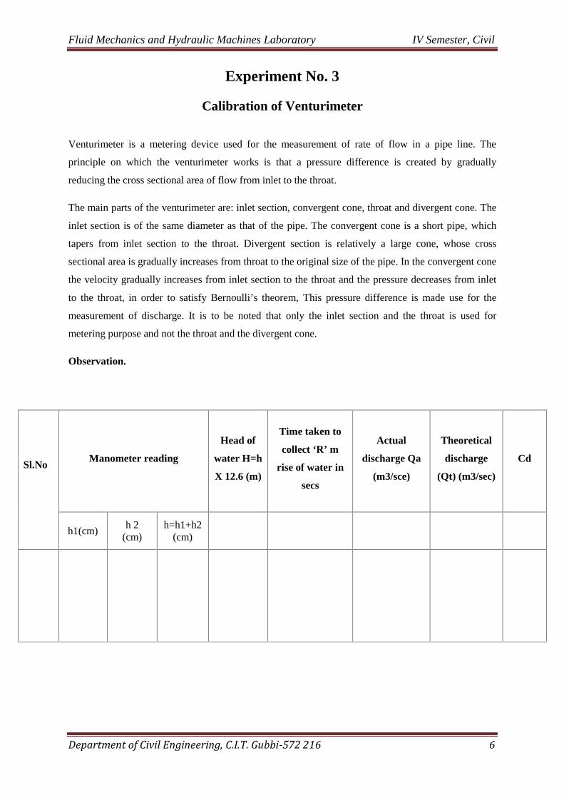
Observation.
[[
Sl.NoManometer reading
Head of
water H=h
X 12.6 (m)
Time taken to
collect ‘R’ m
rise of water in
secs
Actual
discharge Qa
(m3/sce)
Theoretical
discharge
(Qt) (m3/sec)
Cd
h1(cm)h 2
(cm)h=h1+h2
(cm)

Fluid Mechanics and Hydraulic Machines Laboratory IV Semester, Civil
Department of Civil Engineering, C.I.T. Gubbi-572 216 7
The discharge equation for the venturimeter is:
22
12
21 2
AA
gHAACQ d
Where A1 is the cross sectional area of flow at the inlet
A2 is the cross sectional area of flow at the throat
H is the venturimeter head
Cd is the coefficient of discharge
the above equation can be written as:
in general HKQ , where
`2
22
12
21
AA
gAACK d
And therefore, `221
22
12
gAA
AAKCd
Aim of the experiment: To determine the coefficient of discharge Cd constant K & the index N.
Apparatus required: Venturimeter experimental setup, stop watch, measuring tank and scalevernier-caliperse.
Experimental procedure:
1. Note down the dimensions of the measuring tank.
2. Measure the diameter of the section and throat by using a vernier-caliperse.
3. By operating the inlet valve adjust the flow through the venturimeter
4. Note down the differences in levels of mercury column in the two limbs of the differentialmanometer.
5. By using a stop watch, register the time taken in seconds to collect 5 cm rise of water in themeasuring tank.
6. Repeat the steps 4 & 5 for 5 or 6 times by increasing the discharge through the venturimetereach time.
7. Draw a graph of Q v/s H on a log-log scale.
8. Calculate the values of Cd & N.

Fluid Mechanics and Hydraulic Machines Laboratory IV Semester, Civil
Department of Civil Engineering, C.I.T. Gubbi-572 216 8
Specimen Calculations: For Trail No. I
Area of the inlet, A1 = 212
4m
d
=
Area of the inlet, A2 = 222
4m
d
=
Venturimeter head, H = X
1
1
2
S
Smeter of water
Where,S1 = Specific gravity of water = 1S2 = Specific gravity of mercury = 13.6D1= Diameter of inlet sectionD2= Diameter of throat sectionX = Deflection of mercury column in the two limbs of differential manometer in m
Secmt
LxBxhQ /3
Where,
L = Length of the collecting tank in mB = Breadth of the collecting tank in mH = Rise in water level in time t sec = 5 cm
Plot Q vs H on a log-log graphFrom the graph, the slope of the line, N=
When H=1, Q = K, and therefore,gAA
AAKCd
221
22
12

Fluid Mechanics and Hydraulic Machines Laboratory IV Semester, Civil
Department of Civil Engineering, C.I.T. Gubbi-572 216 9
TABLE -4
Calibration of Venturimeter
Dimensions of measuring tank:Length, L = mBreadth, B = mHeight of water, h =
Diameter of inlet, d1 = m Diameter of throat, d2 = m
Sl.No.
Deflection ofdifferential
manometer, x (cmof Hg)
Venturimeter head,H=x(S2/S1-1)
(meter of water)
Time taken to collect 5 cmrise of water in the
measuring tank, t (seconds)
Q(LxBxh)/t(m3/Sec)
1.
2.
3.
4.
5.
Conclusions:

Fluid Mechanics and Hydraulic Machines Laboratory IV Semester, Civil
Department of Civil Engineering, C.I.T. Gubbi-572 216 10
Experiment No. 4
Calibration of Venturiflume
Venturiflume is a metering device used for the measurement of rate of flow in open channel. The
basic principle on which the venturiflume works is same as that of an venturimeter.
The main parts of the venturiflume are: inlet section, convergent section, throat and divergent section.
The inlet section is same as that of the approach channel. The convergent section tapers from inlet
section to the throat. Divergent section is relatively large, whose cross sectional area is gradually
increases from throat to the original size of the channel. In the convergent section the velocity
gradually increases from inlet section to the throat and the pressure head decreases from inlet to the
throat, in order to satisfy Bernoulli’s theorem. The pressure head difference is made use for the
measurement of discharges. It is to be noted that only the inlet section and the throat is used for
metering purpose and not the throat and the divergent section.
The discharge equation for the venturiflume is:.
22
12
21 2
AA
gHAACQ d
Where
A1 is the cross sectional area of the approach channel
A2 is the cross sectional area of flow at the throat
H is the venturiflume head
Cd s the coefficient of discharge
the above equation can be written as:
In general, Q = K √H, where
22
12
21 2
AA
gAACK d
And therefore,gAA
AAKCd
221
22
12

Fluid Mechanics and Hydraulic Machines Laboratory IV Semester, Civil
Department of Civil Engineering, C.I.T. Gubbi-572 216 11
Aim of the experiment: To determine the coefficient of discharge Cd constant K & the index N.
Apparatus required: Venturiflume experimental setup, stop watch, measuring tank and scale
Experimental procedure:1. Note down the dimensions of the measuring tank.
2. Measure the width of the approach channel and throat by using a scale.
3. By operating the inlet valve adjust the flow through the venturiflume.
4. Note down the head differences at the approach channel and the throat by using hook gauges.
5. By using a stop watch, register the time taken in seconds to collect 5 cm rise of water in themeasuring tank.
6. Repeat the steps 4 & 5 for 5 or 6 times by increasing the discharge through he venturiflumeeach time.
7. Draw a graph of Q v/s H or a og log scale.
8. Calculate the values of Cd & N.
Specimen Calculations: For Trail No. I
Area of the inlet, A1 = B (width of approach channel) x H1 (Head difference at the approach channel)= m2
Area of the throat, A2 = B (width of the throat) x H2 (Head difference at the throat) = rn2
Venturiflume head, H=H1-H2 = metre of water
Secmt
LxBxhQ /3
Where,
L = length of the collecting tank in m
B = breadth of the collecting tank in m
h = rise in water level in time t sec = 5 cm
Plot Q vs H on a log-log graph
From the graph, the slope of the line, N=
When H=1, Q =K, and therefore,gAA
AAKCd
221
22
12

Fluid Mechanics and Hydraulic Machines Laboratory IV Semester, Civil
Department of Civil Engineering, C.I.T. Gubbi-572 216 12
TABLE -5
Calibration of Venturiflume
Dimensions of measuring tank:Length, L = mBreadth, B m = mHeight of water, h = 5cm
Least count of hook gauge = mm
SlNo
Head at approach channel Head at the throat
Qactual
(m3/sec)
Final hookgauge
readings(cm)
Initialhook gauge
readings(cm)
DifferenceH (m)
Final hookgauge
readings(cm)
Initialhookgauge
readings(cm)
DifferenceH1 (m)
1
2
3
4
5
6
Conclusions:

Fluid Mechanics and Hydraulic Machines Laboratory IV Semester, Civil
Department of Civil Engineering, C.I.T. Gubbi-572 216 13
Experiment No. 5
Determination of Hydraulic Coefficients for an Orifice or A Mouthpiece
Aim of the experiment: To determine the hydraulic coefficients Cd, Cv, Cc, and Cr for a given orificeor a mouthpiece.
Apparatus required: Experimental setup of orifices, points gauge, stop watch, measuring tank, scaleand vernier calipers.
Experimental procedure:
1. By using slide caliperse, find out the diameter of the given orifice or a mouthpiece.
2. Note down the dimensions of the measuring tank.
3. By operating the inlet valve, maintain a constant head(h) over the orifice.
4. Note down the required to collect 5 cm rise of water in the collecting tank.
5. By using point gauge measure the x and y co-ordinates from vena-contract a section.
6. Repeat the steps 4 & 5 by varying the head over the orifice or a mouthpiece.
Specimen Calculations: For Sl. No. 1
A. OrificeArea of orifice,
22
4mda
Theoretical discharge, SecmghaQth /2 3
Actual discharge, Secmt
LxBxHQact /3
Coefficient of discharge, th
actd Q
QC
Coefficient of velocity,yh
xCv 4
2
Coefficient of contraction,
1
12
v
rC
C
Where,
d = diameter of Orifice
H = head over the orifice
L = Length of the collection tank
B = breath of the collecting tank
H= rise in water level in time t SecX,Y are the horizontal and vertical co-ordinates of any point on the jet measured from vena-
contracta section.
Fluid Mechanics and Hydraulic Machines Laboratory IV Semester, Civil
Department of Civil Engineering, C.I.T. Gubbi-572 216 14
Conclusions:
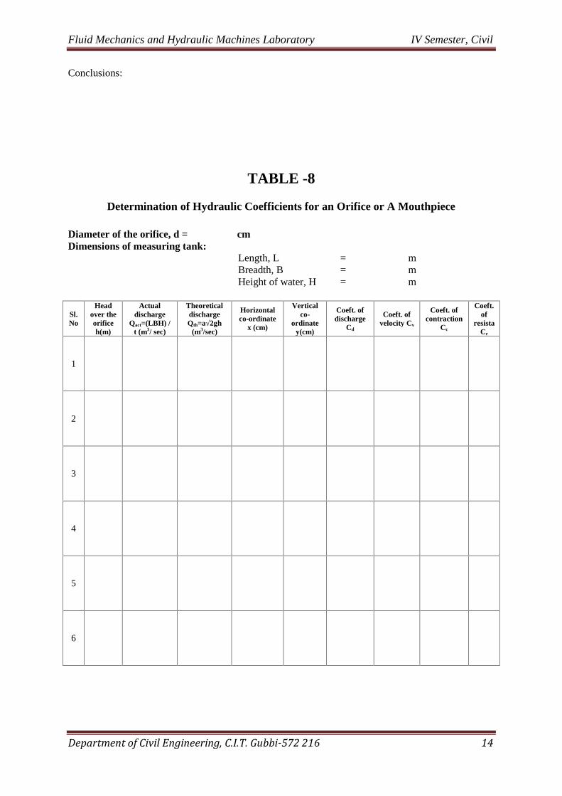
TABLE -8
Determination of Hydraulic Coefficients for an Orifice or A Mouthpiece
Diameter of the orifice, d = cmDimensions of measuring tank:
Length, L = mBreadth, B = mHeight of water, H = m
Sl.No
Headover theorificeh(m)
Actualdischarge
Qact=(LBH) /t (m3/ sec)
TheoreticaldischargeQth=a√2gh
(m3/sec)
Horizontalco-ordinate
x (cm)
Verticalco-
ordinatey(cm)
Coeft. ofdischarge
Cd
Coeft. ofvelocity Cv
Coeft. ofcontraction
Cc
Coeft.of
resistaCr
1
2
3
4
5
6

Fluid Mechanics and Hydraulic Machines Laboratory IV Semester, Civil
Department of Civil Engineering, C.I.T. Gubbi-572 216 15
Specimen Calculations: For Sl.No.1
B. Standard Cylindrical Mouthpiece
Area of mouth piece,
22
4mda
Theoretical discharge, sec/2 3mghaQth
Actual discharge, sec/3mt
LxBxHQact
Coefficient of discharge, th
actd Q
QC
Coefficient of velocity, Cv = Cd
Coefficient of contraction, )(1 cvdc xCCCC
Coefficient of resistance,
1
12
v
rC
C
Where, d = diameter of mouthpiece
H = head over the mouthpiece
L = lenath of the collecting tank
B = breadth of the collecting tank
H = rise in water eve in time t sec
Conclusions:

Fluid Mechanics and Hydraulic Machines Laboratory IV Semester, Civil
Department of Civil Engineering, C.I.T. Gubbi-572 216 16
TABLE -8 (B)
DETERMINATION OF HYDRAULIC COEFFICIENTS FOR MOUTH PIECE
Diameter of the mouth piece, d= cm
Dimensions of measuring tank:Length, L = mBreadth, B = mHeight of water, H = m
Sl.No
Head over themouth piece
H (m)
Actual dischargeQact(LxBxH)/t
(m3/sec)
TheoreticaldischargeQth=a√2gh
(m3/sec)
Coefficientof discharge Cd
HorizontalCoordinate(x)
VerticalCo-ordinate
(y)
Coefficientof velocity Cv
Coefficientof
resistance Cr
1.
2.
3.
4.
5.
6.
Conclusions:
Fluid Mechanics and Hydraulic Machines Laboratory IV Semester, Civil
Department of Civil Engineering, C.I.T. Gubbi-572 216 17
Experiment No. 9
Impact of Jet on Vanes
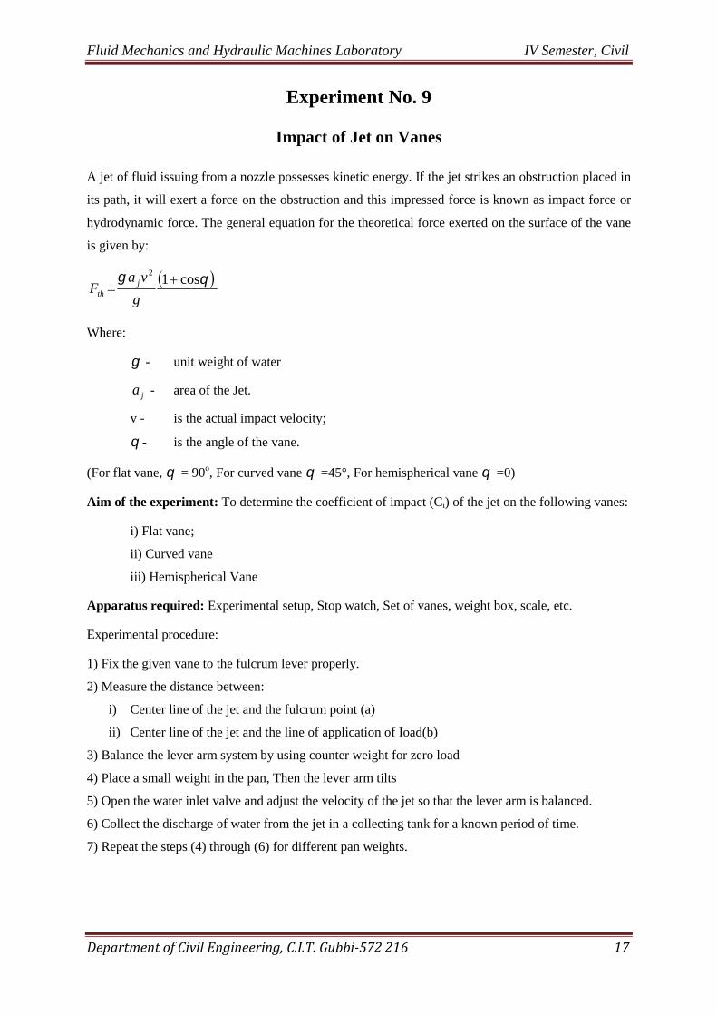
A jet of fluid issuing from a nozzle possesses kinetic energy. If the jet strikes an obstruction placed in
its path, it will exert a force on the obstruction and this impressed force is known as impact force or
hydrodynamic force. The general equation for the theoretical force exerted on the surface of the vane
is given by:
cos12
g
vaF j
th
Where:
- unit weight of water
ja - area of the Jet.
v - is the actual impact velocity;
- is the angle of the vane.
(For flat vane, = 90o, For curved vane =45°, For hemispherical vane =0)
Aim of the experiment: To determine the coefficient of impact (Ci) of the jet on the following vanes:
i) Flat vane;
ii) Curved vane
iii) Hemispherical Vane
Apparatus required: Experimental setup, Stop watch, Set of vanes, weight box, scale, etc.
Experimental procedure:
1) Fix the given vane to the fulcrum lever properly.
2) Measure the distance between:
i) Center line of the jet and the fulcrum point (a)
ii) Center line of the jet and the line of application of Ioad(b)
3) Balance the lever arm system by using counter weight for zero load
4) Place a small weight in the pan, Then the lever arm tilts
5) Open the water inlet valve and adjust the velocity of the jet so that the lever arm is balanced.
6) Collect the discharge of water from the jet in a collecting tank for a known period of time.
7) Repeat the steps (4) through (6) for different pan weights.
Fluid Mechanics and Hydraulic Machines Laboratory IV Semester, Civil
Department of Civil Engineering, C.I.T. Gubbi-572 216 18
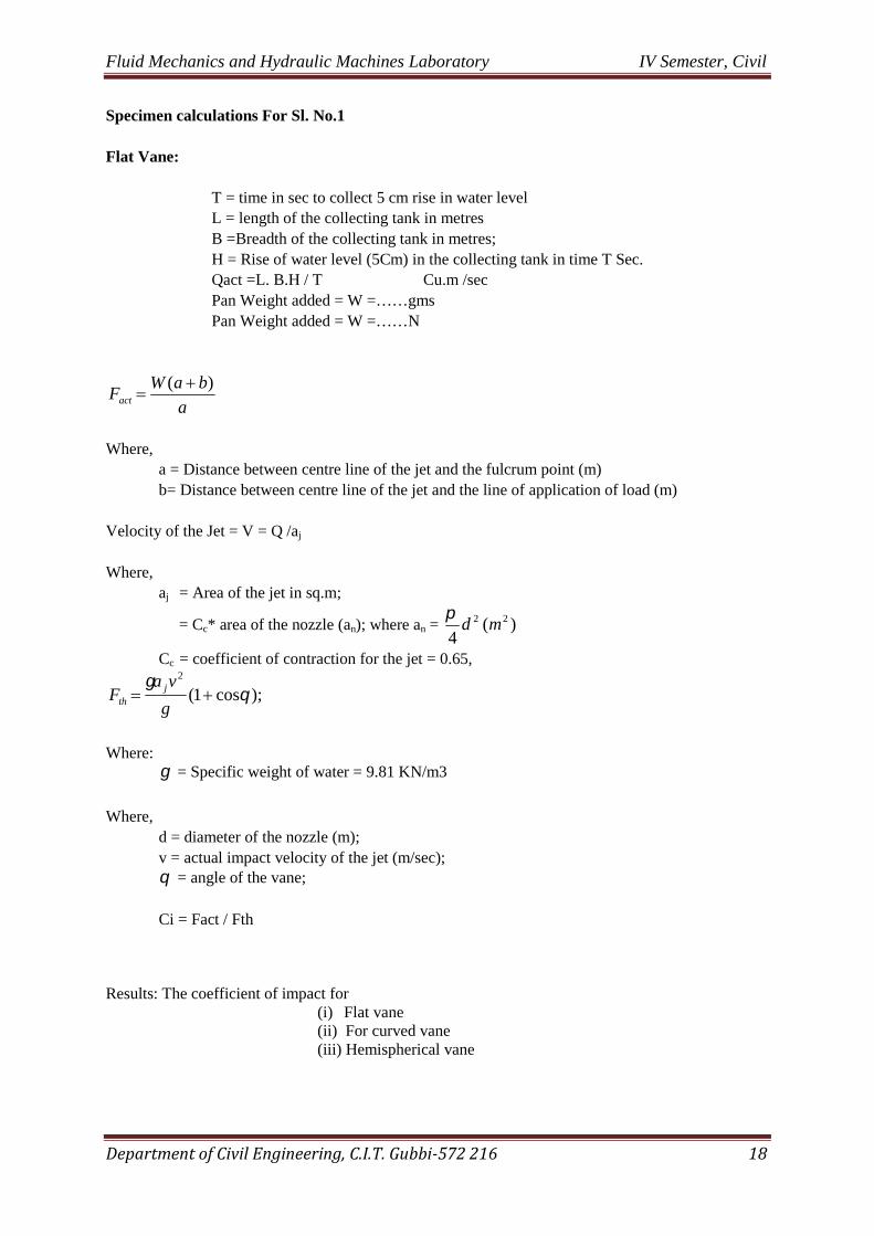
Specimen calculations For Sl. No.1
Flat Vane:
T = time in sec to collect 5 cm rise in water levelL = length of the collecting tank in metresB =Breadth of the collecting tank in metres;H = Rise of water level (5Cm) in the collecting tank in time T Sec.Qact =L. B.H / T Cu.m /secPan Weight added = W =……gmsPan Weight added = W =……N
a
baWFact
)(
Where,a = Distance between centre line of the jet and the fulcrum point (m)b= Distance between centre line of the jet and the line of application of load (m)
Velocity of the Jet = V = Q /aj
Where,aj = Area of the jet in sq.m;
= Cc* area of the nozzle (an); where an = )(4
22 md
Cc = coefficient of contraction for the jet = 0.65,
);cos1(2
g
vaF j
th
Where: = Specific weight of water = 9.81 KN/m3
Where,d = diameter of the nozzle (m);v = actual impact velocity of the jet (m/sec); = angle of the vane;
Ci = Fact / Fth
Results: The coefficient of impact for(i) Flat vane(ii) For curved vane(iii) Hemispherical vane

Fluid Mechanics and Hydraulic Machines Laboratory IV Semester, Civil
Department of Civil Engineering, C.I.T. Gubbi-572 216 19
TABLE - 9
Impact of Jet on Vanes
Dia. Of nozzle (m) =Length of measuring tank (m) =Breadth of measuring tank (m) =Lever arms constants: a = b=
Sl.No
Type ofvane
Time insec(t)
Pan wt. ingms
Pan wt.in N
Discharge Q(m3)/ sec
velocity V(m3 / sec) Fth (N) Fact (N) Ci
1.
2.
3.
4.
Flat
vane
1.
2.
3.
4.
Curved
Vane
1.
2.
3.
4.
Hemispherical
vane

Fluid Mechanics and Hydraulic Machines Laboratory IV Semester, Civil
Department of Civil Engineering, C.I.T. Gubbi-572 216 20
PUMPS
A pump is a mechanical device, which converts the mechanical energy, applied to it from an external
source, into hydraulic energy and transfers the same to the liquid thereby increasing the energy of the
flowing liquid.
The pumps may be classified as;
1. Positive — displacement pumps and
2. Roto-dynamic pumps
In positive displacement pumps, the liquid is sucked and then it is actually pushed or displaced due to
the thrust exerted on it by a moving member, which results in lifting the liquid to the required height.
Ex. Reciprocating pump.
In Roto dynamic pump, there is a rotating element, called impeller, while the liquid passes over the
impeller, its angular momentum changes, due to which the pressure energy of the Iiquid is increased.
Ex. Centrifugal pump.
The Centrifugal pump has greater discharging capacity than a reciprocating pump.
Specific speed of a centrifugal pump
it s defined a the speed of a geometrically similar pump, which delivers on litre of liquid p second
against a head of one metre and is denoted by “Na”.
The specific speedm
S H
QNN
4/3
Where:
N speed of the pump in r.p.m;
Q =discharge of the pump in l.p.s;
Hm =manometric head in metres of water.

Fluid Mechanics and Hydraulic Machines Laboratory IV Semester, Civil
Department of Civil Engineering, C.I.T. Gubbi-572 216 21
Experiment No. 10
Single Stage Centrifugal Pump
Centrifugal pump is so named because it works on the principle of centrifugal action. It consists of animpeller rotating within a casing. The impeller is made up of a number of curved vanes which areenclosed on both the sides by plates known as shrouds. Fluid enters the central portion of the impellercalled the eye, flows radially outwards and is discharged around the entire circumference of thecasing. During the flow over the rotating impeller and the volute casing, the fluid receives energy,resulting in an increase of dynamic pressure.
Centrifugal pumps are classified as follows:
1) Single stage centrifugal pump
2) Multi-stage centrifugal pump.
In case of single stage centrifugal pump, there will be only one impeller on the pump shaft and it canbe used to lift water upto a head of 30 metres
If there are more than one impellers on the pump shaft then it is known as multistage centrifugalpump.
Aim of the experiment: To study the performance of pump under varying conditions of speed, head,and to determine the efficiency of the “ip.
Apparatus required: Stop watch, Tachometer, centrifugal pump test rig., etc.
Experimental procedure:
1. Close the delivery valve completely and prime the pump;
2. Start the pump at a constant speed;
3. Open the delivery valve gradually to get the required head of water.
4. Note down the following:
a) Speed of the pump (N) in rpm
b) Suction head (H3);
c) Delivery head (Hd);
d) Watt meter reading Wi and w2;
e) Hook gauge reading (h); for measuring actual discharge
5. Experiment is repeated for different valve positions and for different speeds.
Fluid Mechanics and Hydraulic Machines Laboratory IV Semester, Civil
Department of Civil Engineering, C.I.T. Gubbi-572 216 22
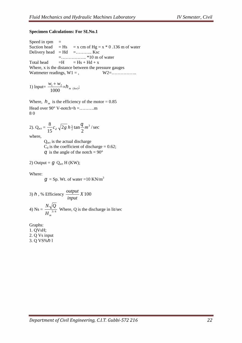
Specimen Calculations: For SLNo.1
Speed in rpm =Suction head = Hs = x cm of Hg = x * 0 .136 m of waterDelivery head = Hd =……….. Ksc
=…………….. *10 m of waterTotal head =H = Hs + Hd + xWhere, x is the distance between the pressure gaugesWattmeter readings, W1 = , W2=……………..
1) lnput= ;1000 )(
21kwm
ww
Where, m is the efficiency of the motor = 0.85
Head over 90° V-notch=h =……….m8 0
2). Qact = sec/2
tan215
8 325 mhgcd
where,Qact is the actual dischargeCd is the coefficient of discharge = 0.62; is the angle of the notch = 90°
2) Output = Qact H (KW);
Where: = Sp. Wt. of water =10 KN/m3
3) , % Efficiency 100Xinput
output
4) Ns =4/3
mH
QNWhere, Q is the discharge in lit/sec
Graphs:1. QVsH;2. Q Vs input3. Q VS% l

Fluid Mechanics and Hydraulic Machines Laboratory IV Semester, Civil
Department of Civil Engineering, C.I.T. Gubbi-572 216 23
TABLE -10
Single Stage Centrifugal Pump
Sl. NoSpeed(rpm)
Suction head Deliverypressure
(KgIcm2)
Deliveryhead inm. of
water (Hd)
Totalhead in
m.of water(Hm)
Watt meterreading
Hook gaugereading Dischar
ge Q(m3/s)
Input(Kw)
Output(KW)
0(%)
Specificspeed(Na)Cm of
Hg
m. ofwater(Hs)
W1 W2 Fin In Diff

Fluid Mechanics and Hydraulic Machines Laboratory IV Semester, Civil
Department of Civil Engineering, C.I.T. Gubbi-572 216 24
HYDRAULIC TURBINES
Hydraulic turbines are the machines used to convert hydraulic energy of water into mechanicalenergy. The mechanical energy so developed will be used to generate electrical power by directlycoupling generator with the shaft of the turbine.
Hydraulic Turbines are classified as:
i) Impulse turbineii) Reaction turbine or pressure turbine.
Every turbine, whether Impulse/Reaction has the following parts:
A wheel commonly known as a runner having vanes around its circumference which rotates under theaction of water gliding on the vanes. The guiding mechanism guides the water to the vanes of therunner. From the source of supply. water enters the turbine through a conduit known as penstock. Thewater after gliding over the moving vanes ultimately falls into the tailrace.
In impulse turbine, the Jet of water issuing from the nozzle directly strikes the vanes of the runner.The hydraulic energy of water gets directly converted to Kinetic energy, which will run the blades ofthe turbine. Therefore, the water leaving the turbine is at atmospheric pressure.
In the case of reacfon turh.s the wt& enters the wheel, glides over the vanes of the runner and flowsthrough the draft tuoe before leaving the turbine. The pressure energy of water gets converted intoKinetic energy gradually. The pressure of water leaving the turbine is below the atmospheric pressure.Therefore a draft tube is necessary to lead the water from the outlet of the turbine to the tailrace.
Example: Francis turbine, Kaplan turbine.
Unit Characteristics:
i) Unit power (Pa): is defined as the power (P) developed theoretically by a given turbine whenworking under one metre head, while the overall efficiency of the turbine remains constant.
2/3H
PPu
ii) Unit Speed (Ne): is defined as the theoretical speed (N) of a given turbine, when working underone metre head, while the overall efficiency remains constant.
H
NNu
iii) Unit discharge (Q): is defined as the discharge (Q) of turbine when working under a net head ofone metre.
H
QQu
iv) Specific speed (Nb): The specific speed of a turbine may be defined as the speed (N) of ageometrically similar turbine which develops a unit power when working under a head of 1m
45H
QN S
These characteristics are used in classifying the turbines.

Fluid Mechanics and Hydraulic Machines Laboratory IV Semester, Civil
Department of Civil Engineering, C.I.T. Gubbi-572 216 25
Experiment No. 11
Pelton Wheel Turbine
Pelton wheel is a tangential flow impulse turbine. The powerful jet issued from the nozzle impingeson the buckets provided on the periphery of the wheel. The buckets have the shape of a double semi-ellipsoidal cups. Each bucket is divided into two symmetrical parts by a sharp edged ridge known assplitter.
Aim of the experiment: To study the performance of pelton wheel under varying condition of head,speed and gate opening.
Apparatus required: Stop watch. Tachometre, Pelton wheel etc.,
Experimental procedure:
1) Prime the centrifugal pump provided to supply the required head of water to the turbine an start itwith the gate valve closed. The spear head in the turbine should also oe in the closed position.
2) Gradually open the discharge valve by rotating the hand wheel until the turbine attains the normalhead / speed.
Constant speed characteristics:
1) Gradually open the spear head valve, and set it at the required gate opening(1/4, 1/2 3/4, 1) and run theturbine at required speed (say 800 rpm).
2) Note down the following for no load condition:
a) Pressure gauge reading (supply head);
b) Load on the brake drum;
c) Spring balance reading;
d) Manometer reading;
3) Load the turbine by keeping dead weight on the brake drum and bring back the speed to 800 rpmby throttling the discharge valve, and note down the above set of readings as in step2.
Constant head characteristics:
1. Set the spearhead at a required gate opening (1/4, Y2, 3/4, 1), and run the turbine at the requiredhead (say 2 Ksc)
2. Note down the following for no load condition;
a) Pressure gauge rading (supply head);
b) Speed of the turbine;
c) Load on the brake drum;
d) Spring balance reading;
e) Manometer reading;

Fluid Mechanics and Hydraulic Machines Laboratory IV Semester, Civil
Department of Civil Engineering, C.I.T. Gubbi-572 216 26
3. Repeat the experiment for loads of 2 kgs, 4 kgs, 6 kgs, arid 8 kgs on the brake drum and tabulatethe reading as in step 4. Repeat the experiment for different gate settings.
Specimen Calculations: For SLNo.1
Diameter at inlet, d1 = 63.8 mmThroat diameter, d2 = 38.1 mm
Area at inlet, A1 = 4
21d
Area at throat, A2 = 4
22d
Supply head = Hs = ……. Ksc= …….m of water
Speed (N) = ……..r.p.m
Venturimeter head = ………m of water
1. Actual Discharge, Q =Sec
m
AA
ghAACd3
22
21
21 2
Where:Cd = Coefficient of discharge for venturi meter (0.98)h = Venturimeter head in meter of water.
2. Input = Q H kw
Where: is the specific weight of water = 10 KN/m3
H = Hs= total head on the turbine in m of waterQ is the discharge of the turbine m3/sec
3. Output P = )(60
))((2kw
rRSWN
Where:N is speed in rpmW is the load on the brake drum in KNR is radius of brake drum in mr is radius of rope in
4. Overall efficiency, 1000 input
output
5. Unit Power,23H
PPu
6. Unit speed, (Nu) =H
N
Fluid Mechanics and Hydraulic Machines Laboratory IV Semester, Civil
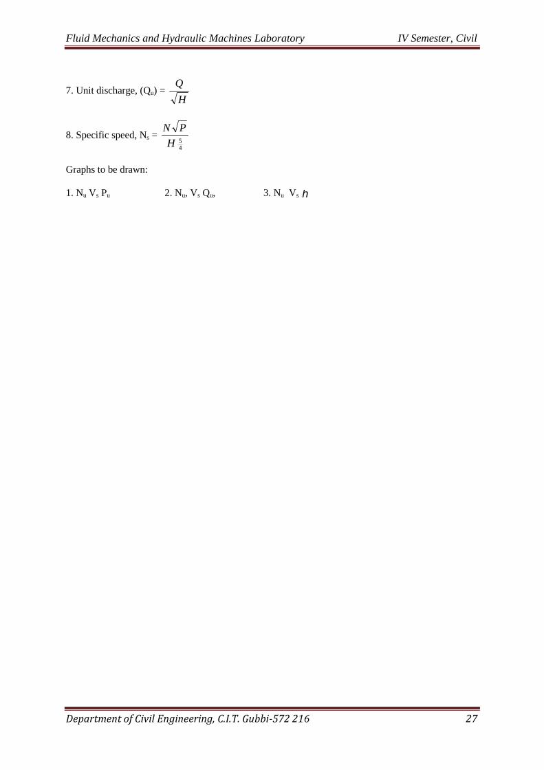
Department of Civil Engineering, C.I.T. Gubbi-572 216 27
7. Unit discharge, (Qu) =H
Q
8. Specific speed, Ns =45H
PN
Graphs to be drawn:
1. Nu Vs Pu 2. Nu, Vs Qu, 3. Nu Vs

Fluid Mechanics and Hydraulic Machines Laboratory IV Semester, Civil
Department of Civil Engineering, C.I.T. Gubbi-572 216 28
TABLE – 11(A)
PELTON WHEEL TURBINE
CONSTANT HEAD
GateSetting
Sl.No
Supplyhead,(Hs)
(kg/cm2
Supplyhead (Hs)
(m. ofwater)(H)
Speed(rpm)
Venturi meterhead (h)
Load (KN)Q
(m3 /sec)
Input(Kw) Output(Kw) 0
(%)
Unitspeed(Nu)
UnitPower(Pu)
Unitdischarge
(Qu)
Specificspeed(Ns)
Cm ofHg
m. ofwater
(h)
Deadload W
SpringLoad
S

Fluid Mechanics and Hydraulic Machines Laboratory IV Semester, Civil
Department of Civil Engineering, C.I.T. Gubbi-572 216 29
TABLE – 11(B)
PELTON WHEEL TURBINE
CONSTANT HEAD
GateSetting
Sl.No
Supplyhead,(Hs)
(kg/cm2
Supplyhead (Hs)
(m. ofwater)(H)
Speed(rpm)
Venturi meterhead (h)
Load (KN)Q
(m3 /sec)
Input(Kw) Output(Kw) 0
(%)
Unitspeed(Nu)
UnitPower(Pu)
Unitdischarge
(Qu)
Specificspeed(Ns)
Cm ofHg
m. ofwater
(h)
Deadload W
SpringLoad
S

Fluid Mechanics and Hydraulic Machines Laboratory IV Semester, Civil
Department of Civil Engineering, C.I.T. Gubbi-572 216 30
Experiment No. 12
Francis Turbine
Francis turbine is a mixed flow reaction turbine in which, water enters the runner radially at its outerperiphery and leaves axially at its center. Before water leaves the turbine, it is made to flow throughthe draft tube into the tailrace. This type of turbine is suitable for medium heads and discharges.
Aim of the experiment: To study the performance of the turbine under varying conditions of head,Ioac and gate openings.
Apparatus required : Stop watch, Tachometer, Francis Turbine test rig, etc.
Experimental procedure:
1. Prime the centrifugal pump provided to supply the desired head of water to the turbine and start itwith gate valve closed.
2. Slowly open the gate valve by rotating the hand wheel until the turbine attains the normal ratedspeed/head
Constant speed:
1. Set the spearhead at the required gate opening (1/4, Y2, %, 1) and run the turbine at required speed(say 800 rpm) by operating thc ate valve.
2. Note down the following for no ioad condition;
a) Pressure gauge reading (both at supply and delivery sides);
b) Load on the brake drum;
c) Spring balance reading;
d) Manometer reading.
3. Load the turbine by keeping dead weight on the brake drum and bring back the speed to 800 rpm byadjusting the discharge valve, and note down the above set of readings as in step 2.
4. Repeat the experiment for different loads and different gate settings.
Constant Head:
1. Set the Spear head at the required opening (1/4, Y2, %, 1). Gradually open the gate valve andmaintain the required head( say 2 Ksc)
2. Note down the following for no load condition;
a) Pressure gauge readings, (both supply and delivery sides)b) Speed of the turbine;c) Load on brake drum;d) Spring balance reading;e) Manometer reading.
3) Repeat the experiment for loads of 2 kgs, 4 kgs, 6 kgs, etc., on the brake drum and tabulatethe readings.

Fluid Mechanics and Hydraulic Machines Laboratory IV Semester, Civil
Department of Civil Engineering, C.I.T. Gubbi-572 216 31
4) Repeat the experiment for different gate settings.
Observations:
1. Inlet dia. of venturimeter = d1 101.60 mm2. Throat dia of venturimeter d2 = 60.96 mm3. Inlet area of venturimeter = Al = 8.1 X l02 sqm.4. Throat area of venturimeTer = A2 2.91 X 10² sqm.
Specimen calculations: For SLN0.1
Constant Head:
Supply head Hs = ………..KscHs= ……m of water
Vacuum Pressure=Hd = .... mm of HgHd = …………m of water
Total Head= H=Hs+Hd+X =…………..:m of waterWhere, X is the distance between pressure gauges
Venturimeter head=h=………….m of water
1. Actual Discharge, Qact =sec
2 3
22
21
21 m
AA
ghAACd
Where:Cd = Coefficient of discharge for venturimeter (0.98)
2. Input QH (kw)
Where: is the specific weight of water =10 KN/m3
3. Output power, P = kwrRSWN
60
))((2
Where:N is speed in rpmW is the load on the brake drum in KN.R is radius of brake drum in metresr is radius of rope in metres

Fluid Mechanics and Hydraulic Machines Laboratory IV Semester, Civil
Department of Civil Engineering, C.I.T. Gubbi-572 216 32
Experiment No. 13
Bernoullis Theorem
Aim: To verify Bernoullis Theorem.Apparatus: Bernoullis experimental set up, stop clock.Theory: The Bernoullis Theorem states that for a perfect incompressible liquid flowing in apipe line the total energy of a particle remains constant while the particle moves from onepoint to another, assuming that there are no frictional losses in the pipe line.Mathematically Bernoullis theorem states,
Z + V2/2g + P/W = ConstantProcedure:
1. Switch on the pump.2. Partially close the “by pass” valve, water flows into the supply tank.3. As the water level rises in the supply tank water starts flowing into the reservoir tank
through the venture test section and the water level in the receiving tank also rises.4. When the water level in both the tanks reaches their respective over flow level, control
the “by pass” valve.5. Allow the water flow to become steady.6. Record the readings of piezometer and the flow rate from the receiving tank against
time by closing the outlet valve of measuring tank for 5cm rise of water level.7. Repeat the experiment for different discharge.8. Tabulate all the readings and calculate to verify the Bernoullis theorem.
Tabular column
Cross section area of collecting tank = 0.104 m2
SI.No.
Headintank 1(mm)
Headintank 2(mm)
Timefor 5cmrise int sec
Piezometer (static head) in mm Qact
m3/sec
Pa Pb Pc Pd Pe Pf Pg Ph Pi Pj Pk
12
3
Observations & calculations:1. Qact = (A×h)/t
2. Diameter of test section from da to dk
da = 25 mm

Fluid Mechanics and Hydraulic Machines Laboratory IV Semester, Civil
Department of Civil Engineering, C.I.T. Gubbi-572 216 33
db = 22.7 mm
dc = 20.4 mm
dd = 18.4 mm
d e= 15.8 mm
df = 13.5 mm
dg = 15.8 mm
dh = 18.4 mm
di = 20.4 mm
dj = 22.7 mm
dk = 25 mm
3. Area of test section at various pressure ports from a to k
Aa = (πda)2/4 m2
Similarly calculate areas from Aa to Ak
4. Velocity of flow for at different cross sections
V = Q/A m/sec
Similarly calculate areas from Va to Vk
5. Velocity head
Vh = V2/2g m
6. Pressure head Ph (from tabular column)
7. Total head (Total Energy) E
E = Ph + Vh
Result

Fluid Mechanics and Hydraulic Machines Laboratory IV Semester, Civil
Department of Civil Engineering, C.I.T. Gubbi-572 216 34
VIVA QUESTIONS
1 What do you mean by gauge and absolute pressure?
2. What do you mean by vacuum pressure?
3. What is a manometer? Describe the different types of manometer?
4. Distinguish between a simple & differential manometer?
5. What do you understand by the term hydrostatic pressure?
6. What is the difference between the specific weight of a substance & its specific gravity?
7. Explain the principle of floatation.
8. Restate Archimede ‘s principle.
9. Define the term centre of buoyancy & metacentre.
10. Restate the equation for continuity of flow.
11. Distinguish clearly between stream lines & streak lines.
12. State Bernoulli’s theorem. Mention its limitations & applications.
13. What do you understand by the term viscosity? What is the relation between the absolute viscosity
& kinematic viscosity?
14. What is meant by Newtonian & non-Nev1an?
15. What are the various instruments used to measure discharge through a pipe, based on the principle
of Bernoulli’s theorem?
16. Define vena-contracta.
17. Define coefficient of contraction, coefficient of velocity & coefficient of discharge for a sharp
edged orifice. What is the relation between them?
18. Distinguish between small & large orifices. What do mean by drowned orifice?
19. What do you mean by venturi head?
20. Can you employ a venturi meter in a vertical position?
21. in a venturi meter usually the length of the divergent outlet part is made longer than that of the
converging infer part. Why?
22. What are the relative advantages of venturi & orifice meters?
23. Define velocity of approach.
24. What is a notch?
25. Why a V-notch is preferred to a rectangular notch for measuring discharge?
26. What is weir? How is it different from a notch?
27. Describe a hook gauge.
28. Differentiate between laminar & turbulent flow? How is the type of flow related to Reynold’s
number?
29. Why there is loss of head when a fluid passes through a pip line? On what factors it depend?

Fluid Mechanics and Hydraulic Machines Laboratory IV Semester, Civil
Department of Civil Engineering, C.I.T. Gubbi-572 216 35
30. State the Darcy’s & Chezy’s formula for the determination of loss of head due to friction in pipe.
31. What is an open channel? What are the various types of open channels?
32. What is a hydraulic jump?
33. What is the principle involved in the design of Hydraulic machines?
34. How do you classify turbines?
35. Differentiate between reaction and impulse turbines.
36. How do you select turbines?
37. Why the splitter is provided in the buckets of Pelton wheel?
38. Why the shape of bucket is made hemispherical in Peiton wheel?
39. Why the lower lip of the bucket is notched in Pelton wheel?
40. What is the difference between speed ratio and velocity ratio applicable to turbines?
41. What is the necessity of spiral casing in reaction
42. Why guide blades are provided in Turbines?
43. Why draft tube is provided in reaction turbines? Explain different types of draft tubes.
44. How does cavitation occur in turbines?
45. What is the difference between an impeller and a rotor?
46. How to avoid Water Hammer in turbhes?
47. What are the different types of surge tanks used in turbines?
48. What do you understand by governing of turbines?
49. Explain runaway speed of turbines?
50. What is the difference between Kaplan and Propeller Turbines?
51. Explain unit quantities of turbines. What is the Specific speed of a turbine? What is its
significance?
52. Explain performance characteristic curves of turbines?
53. What are the different types of efficiencies of turbines?
54. How do you classify pumps?
55. What is the difference between rotodynamic and positive dipSacerne’pxnps?
56. Explain slip of a reciprocating pump?
57. When does negative slip occurs in reciprocating pump?
58. Explain indicator diagram.
59. What is the necessity of providing Air Vessels in reciprocating pumps?
60. Why reciprocating pump cannot be run at ‘eiy high speed.
61. What is the difference between Free and Forced Vortex?
62. What is the principle involved in design of centrifugal pumps?
63. Why priming needed in centrifugal pump?
64. What are parts of a centrifugal pump?
65. Why Volute Casing and Vortex Casing are needed in centrifugal pump?

Fluid Mechanics and Hydraulic Machines Laboratory IV Semester, Civil
Department of Civil Engineering, C.I.T. Gubbi-572 216 36
66. What are the different types of impellers?
67. How do you increase the efficiency o a centrifugal pump?
68. Explain Manometric Head. Write down different types of expressions for manometric head.
69. What are the losses of centrifugal pump?
70. Write shod notes on Efficiencies of centrifugal pump.
71. Why centrifugal pump should be started with minimum speed?
72. Explain the specific speed of a centrifugal pump.
73. What are Multi-Stage Centrifugal pumps?
74. What type of pump you suggest in the following instances:
a) Multistoried building;
b) Irrigation purpose;
c) Liffing muddy water.
75. What are the characteristic curves of a centrifugal pump?
76. Explain positive suction head of a centrifugal pump.
77. Why does Cavitation occur in centrifugal pump?
78. Explain Thomas’ Cavitation factor.
79. What is suction specific speed of a centrifugal pump?
80. What are the priming devices used in centrifugal pumps?
81. What is the principle on which Hydraulic Ram is designed?
82. What is the significance of beats in Hydraulic Ram?