california dealer stamp - master hire...only genuine terex spare parts must be used when the machine...
TRANSCRIPT

TEREX, Central Boulevard, ProLogis Park, Coventry CV6 4BX, EnglandTel.: +44 (0)2476 339400 - Fax: +44 (0)2476 339500
www.terexce.com - Email : [email protected] - [email protected]
CALIFORNIAProposition 65 Warning
Diesel engine exhaust and some of its constituentsare known to the State of California to causecancer, birth defects, and other reproductive harm.
CALIFORNIAProposition 65 Warning
Battery posts, terminals and related accessoriescontain lead and lead compounds, chemicalsknown to the State of California to cause cancerand reproductive harm. Wash hands afterhandling.
WARNINGNoise Level at Drivers Ear
Exceeds 85dB(A)
Dealer Stamp
Operators Instruction Book
TV800, TV800H, TV900Tandem Vibratory Roller
Kubota Engine - Poclain Drive Motors
Publication No. 0102GB-5 April 2011For Machines with Danfoss Drive Motors Refer to 0102GB-4 - August 2010
Original Instructions

1 - Table of ContentsTV800, TV800H, TV900
Roller

1-1 TV800/900 Roller 0102-5 April 2011
Contents
1. Introduction Introduction ....................................................................................................................................................................... 2-1Safety Alert System ........................................................................................................................................................... 2-1Intended Use ...................................................................................................................................................................... 2-1Instruction Manual ............................................................................................................................................................ 2-1Service or Spares Enquiries ............................................................................................................................................... 2-2Warranty and Maintenance ............................................................................................................................................... 2-2Official Documents ............................................................................................................................................................ 2-2
2. SafetyGeneral Safety ................................................................................................................................................................... 3-1Safety Alert Symbol .......................................................................................................................................................... 3-1Hazard Classification ........................................................................................................................................................ 3-1General Safety Notes ......................................................................................................................................................... 3-1Personal Protective Equipment (PPE) ............................................................................................................................... 3-2General Safety Information ............................................................................................................................................... 3-3Safety Interlock System ..................................................................................................................................................... 3-4ROPS ................................................................................................................................................................................. 3-4Seat Belt ............................................................................................................................................................................ 3-4Hydraulic Fluid .................................................................................................................................................................. 3-5Fluid Levels ....................................................................................................................................................................... 3-5Frozen Battery Electrolyte ................................................................................................................................................. 3-5Fires ................................................................................................................................................................................... 3-5Water Cooled Engines ....................................................................................................................................................... 3-5Lubricants .......................................................................................................................................................................... 3-6Hygiene ............................................................................................................................................................................. 3-6Storage ............................................................................................................................................................................... 3-6Handling Oil ...................................................................................................................................................................... 3-6
New Oil ....................................................................................................................................................................... 3-6Old Oil ......................................................................................................................................................................... 3-6
First Aid - Oil .................................................................................................................................................................... 3-7Swallowing Oil ............................................................................................................................................................ 3-7Skin Contact ................................................................................................................................................................ 3-7Eye Contact ................................................................................................................................................................. 3-7
Oil or Fuel Spillage ........................................................................................................................................................... 3-7Fires ................................................................................................................................................................................... 3-7Gradients ........................................................................................................................................................................... 3-8
Slopes - Diagram A ..................................................................................................................................................... 3-8Maximum Slope Gradient - Diagram B ...................................................................................................................... 3-8
Gradients ........................................................................................................................................................................... 3-9Crossing Gradients - Diagram C ................................................................................................................................. 3-9
Description of Symbols and Pictorials Used on Safety Signs ........................................................................................... 3-10Description of Symbols and Pictorials Used on Safety Signs ........................................................................................... 3-11Safety Decals ..................................................................................................................................................................... 3-12Safety Decals ..................................................................................................................................................................... 3-13
4. InstallationDelivery Checks ................................................................................................................................................................ 4-1Articulation Lock .............................................................................................................................................................. 4-1Pre-Start Checks ................................................................................................................................................................ 4-2

Contents
TV800/900 Roller 0102-5 April 2011 1-2
5.DescriptionTV800 ............................................................................................................................................................................... 5-1General Description .......................................................................................................................................................... 5-2
Chassis ........................................................................................................................................................................ 5-2Steering ....................................................................................................................................................................... 5-2Drums .......................................................................................................................................................................... 5-2Engine ......................................................................................................................................................................... 5-2Fuel System ................................................................................................................................................................. 5-2Electrical System ........................................................................................................................................................ 5-2Hydrostatic Transmission ........................................................................................................................................... 5-2Drive Control Lever .................................................................................................................................................... 5-2Braking System ........................................................................................................................................................... 5-2Vibration System ........................................................................................................................................................ 5-2Water Sprinkler System .............................................................................................................................................. 5-2Hydraulic Breaker Connection (Optional) .................................................................................................................. 5-2
Battery Isolator .................................................................................................................................................................. 5-3Anti Theft Cover ............................................................................................................................................................... 5-3Circuit Breakers ................................................................................................................................................................ 5-4Emergency Stop Button .................................................................................................................................................... 5-4Hour Meter ........................................................................................................................................................................ 5-4Control Panel ..................................................................................................................................................................... 5-5Warning Lights .................................................................................................................................................................. 5-6
A - Work/RTA Lights (If fitted) ................................................................................................................................. 5-6B - Battery Charge ...................................................................................................................................................... 5-6C - Water Temperature ............................................................................................................................................... 5-6D - Cold Start Heater .................................................................................................................................................. 5-6E - Oil Pressure ........................................................................................................................................................... 5-6F - Indicator Light ....................................................................................................................................................... 5-6
Start Switch ....................................................................................................................................................................... 5-6Work Lights (When fitted) ................................................................................................................................................ 5-7Hazard Lights Switch (When Fittted) ............................................................................................................................... 5-7Direction Indicator Switch (When Fitted) ......................................................................................................................... 5-7Warning Horn .................................................................................................................................................................... 5-8Drive Control Lever .......................................................................................................................................................... 5-9
Drive Control Lever - Functions.................................................................................................................................. 5-9Drive Control Lever .......................................................................................................................................................... 5-10
Vibration Button ......................................................................................................................................................... 5-10Hand Throttle .................................................................................................................................................................... 5-10Single or Double Drum Vibration Valve .......................................................................................................................... 5-11Water Sprinkler System .................................................................................................................................................... 5-11
Tank ............................................................................................................................................................................ 5-11Gravity System Sprinkler Valve ................................................................................................................................. 5-11Pressurised Sprinkler System (Option) ....................................................................................................................... 5-11
Breaker Switch (when fitted) ........................................................................................................................................... 5-12Hydraulic Breaker Connections ........................................................................................................................................ 5-12Flashing Beacon ................................................................................................................................................................ 5-13ROP’S ............................................................................................................................................................................... 5-14
Rigid ROPS ................................................................................................................................................................. 5-14Folding ROPS ............................................................................................................................................................. 5-14
6. InspectionGeneral Inspection ............................................................................................................................................................ 6-1Daily Operator Checks ...................................................................................................................................................... 6-2

1-3 TV800/900 Roller 0102-5 April 2011
Contents
7. Operating InstructionsOperating Instructions ....................................................................................................................................................... 7-1Safety Clothing .................................................................................................................................................................. 7-1Pre-Start Checks ................................................................................................................................................................ 7-1Folding ROPS - when fitted .............................................................................................................................................. 7-2
Folding Procedure ....................................................................................................................................................... 7-2Access/Egress ..................................................................................................................................................................... 7-3Seat Adjustment ................................................................................................................................................................ 7-4
Fore and Aft Movement ............................................................................................................................................... 7-4Weight Adjustment ..................................................................................................................................................... 7-4Back Rest Angle Adjustment ...................................................................................................................................... 7-4
Seat Adjustment ................................................................................................................................................................ 7-5Seat Belt ...................................................................................................................................................................... 7-5
To Start The Engine .......................................................................................................................................................... 7-6To Stop The Engine ........................................................................................................................................................... 7-6To Move the Roller ........................................................................................................................................................... 7-7To Stop the Roller ............................................................................................................................................................. 7-7Parking The Roller ............................................................................................................................................................ 7-7To Select Vibration ........................................................................................................................................................... 7-8Towing the Roller .............................................................................................................................................................. 7-9
To Release the brakes .................................................................................................................................................. 7-9To Re-instate the Brakes ............................................................................................................................................. 7-9
8. TransportationTransportation ................................................................................................................................................................... 8-1
Loading on to a Lorry/Trailer using Ramps ................................................................................................................ 8-1Unloading .................................................................................................................................................................... 8-1
Transportation ................................................................................................................................................................... 8-2Loading or Unloading using a Crane .......................................................................................................................... 8-2Articulation Lock ........................................................................................................................................................ 8-2
Transportation ................................................................................................................................................................... 8-3Tie Down Points .......................................................................................................................................................... 8-3
9. MaintenanceMaintenance and Lubrication ............................................................................................................................................ 9-1
Safety Signs ................................................................................................................................................................. 9-1Hydraulic Oil Under Pressure ...................................................................................................................................... 9-1
Cleaning ............................................................................................................................................................................. 9-2Vehicle/Machine Battery - End of Life Disposal ............................................................................................................... 9-2Battery ............................................................................................................................................................................... 9-3
Battery Isolator ............................................................................................................................................................ 9-3Battery Access ............................................................................................................................................................. 9-3Battery Removal .......................................................................................................................................................... 9-3Battery Replacement ................................................................................................................................................... 9-3
Engine Air Cleaner ............................................................................................................................................................ 9-4Air Cleaner Daily Maintenance .................................................................................................................................. 9-4Air Cleaner Servicing .................................................................................................................................................. 9-4Air Filter Cleaning ...................................................................................................................................................... 9-4
Engine Coolant .................................................................................................................................................................. 9-5Topping Up Cooling System ....................................................................................................................................... 9-5Coolant ........................................................................................................................................................................ 9-5
Fuel System ....................................................................................................................................................................... 9-6Fuel Tank .................................................................................................................................................................... 9-6Fuel Filter .................................................................................................................................................................... 9-6
Engine Oil .......................................................................................................................................................................... 9-7Engine Oil Level Checking ......................................................................................................................................... 9-7
Engine Oil .......................................................................................................................................................................... 9-8Engine Oil Draining .................................................................................................................................................... 9-8
Contents
TV800/900 Roller 0102-5 April 2011 1-4
9. Maintenance - ContinuedHydraulic Oil ..................................................................................................................................................................... 9-8
Checking Level ........................................................................................................................................................... 9-8Hydraulic Filter ................................................................................................................................................................. 9-9
To change the element ................................................................................................................................................ 9-9Hydraulic Tank .................................................................................................................................................................. 9-9
Draining ...................................................................................................................................................................... 9-9Refilling ...................................................................................................................................................................... 9-9
Hydraulic Tank .................................................................................................................................................................. 9-10Suction Strainers - Access .......................................................................................................................................... 9-10Suction Strainers - Removal ....................................................................................................................................... 9-10Suction Strainers - Refitting ....................................................................................................................................... 9-10
Hydraulic Tank .................................................................................................................................................................. 9-11Removal ...................................................................................................................................................................... 9-11Replacement ................................................................................................................................................................ 9-11
Water Sprinkler System .................................................................................................................................................... 9-12Water Tank - Filling ................................................................................................................................................... 9-12Draining ...................................................................................................................................................................... 9-12Testing Water Flow .................................................................................................................................................... 9-12
Water Sprinkler System .................................................................................................................................................... 9-13Tank - Removal .......................................................................................................................................................... 9-13Filter ............................................................................................................................................................................ 9-13Tank - Refitting ........................................................................................................................................................... 9-13
Drum Mountings ............................................................................................................................................................... 9-14Centre Pivot & steering Ram ............................................................................................................................................ 9-14Drive Pump Pivot .............................................................................................................................................................. 9-15Scraper Blades ................................................................................................................................................................... 9-15ROPS ................................................................................................................................................................................. 9-16
Introduction ................................................................................................................................................................. 9-16Attachments and/or Modifications .............................................................................................................................. 9-16Maintenance ................................................................................................................................................................ 9-16Repair .......................................................................................................................................................................... 9-16
Seat Belts............................................................................................................................................................................ 9-17Important Facts about Seat Belts ................................................................................................................................. 9-17
Seat Belt maintenance Guidlines ....................................................................................................................................... 9-17Service Schedule ............................................................................................................................................................... 9-18Recommended Lubricants ................................................................................................................................................. 9-19Scrapping th Machine ........................................................................................................................................................ 9-19
10. SpecificationsIntroduction ....................................................................................................................................................................... 10-1Machine Dimensions. ........................................................................................................................................................ 10-2Machine Specifications ..................................................................................................................................................... 10-3Antifreeze Concentrations ................................................................................................................................................. 10-5Noise Emissions ................................................................................................................................................................. 10-4Vibrations........................................................................................................................................................................... 10-4Electric Circuit .................................................................................................................................................................. 10-6Hydraulic Circuit ............................................................................................................................................................... 10-14Hydraulic Circuit - Breaker Option ................................................................................................................................... 10-16Torque Figures .................................................................................................................................................................. 10-18

2 - IntroductionTV800, TV800H, TV900
Roller

2-1 TV800/900 Roller 0102-5 April 2011
Introduction
Introduction
TEREX appreciates your choice of our product for yourapplication. Our number one priority is user safety which is bestachieved by our joint efforts. We feel you can make a majorcontribution to safety if, you as the machines user:• Comply with all relevant National Laws and Local
Regulations.• Read, Understand and Follow the instructions in this and
any other manuals supplied with the machine.• Use Good, Safe Work Practices in a common sense way.• Only Use Trained Operators to operate the machine who
are directed by informed and knowledgeable supervision.
If there is anything in this manual which is not clear or there isinformation which you think should be added, contact theManufacturers Customer Support Department who will dealwith your problem or request.
We reserve the right to make improvements to these machineswithout incurring any need to change these operatinginstructions.
Any modification to this machine which has not been approvedby the Manufacturer in writing immediately invalidates theManufacturers warranty and product liability for any resultingconsequential damage.
Safety Alert System
Intended Use
This machine has been designed and tested to carry out thefunction of compacting materials of the non-cohesive,bituminous and granular varieties. If used correctly they willprovide an effective and safe means of compaction and meet theappropriate performance standards.
Use of this product in any other way is prohibited and contraryto its intended use.
Instruction Manual
Read this instruction manual carefully before operating themachine. Ensure this instruction manual is kept with themachine at all times and is in good condition - replace themanual immediately if it becomes dirty, damaged or has beenlost. Storage for the manual is provided in a waterproofcompartment (A) located in the back of the operator seat.
bA Safety Alert Symbol is used to alert you to potential
personal safety hazards. Obey all safety messages that follow this symbol to avoid possible injury or death.
Machine LEFT and RIGHT HANDAll references in this manual to LEFT and RIGHT areviewed from the Operating Position (Operators Seat)facing forward.
0102-2-001
A

Introduction
TV800/900 Roller 0102- 5 April 2011 2-2
Service or Spares Enquiries
Please state the vehicle type and the Vehicle IdentificationNumber when making enquiries or orders and in all writtencorrespondence.
The Vehicle Identification Number is stamped on a plate (A)located on the rear face of the front frame..
Warranty and Maintenance
The warranty period for the machine, under normalcircumstances, covers the first 1000 operating hours or thefirst 12 months - whichever comes first. These periods beginthe day the machine is handed over or put into operation.
The machine must be used correctly and serviced to themanufacturers recommendations.
The correct grades of fuels, lubricants and coolants must beused at all times and must be new and clean when added to themachine. Failure to follow these rules may lead to failure of themachine.
Servicing and repairs should be carried by the dealers staff whowill be trained and experienced in the necessary skills forsuccessful maintenance of the machine.
Only genuine TEREX spare parts must be used when themachine is serviced or repaired.
All claims during the warranty period will only be accepted ifthe recommended maintenance and service work has beencarried out at the specified intervals.
It is important regular maintenance and service work is carriedout after the warranty period has expired to ensure the machineis safe to use and does not cause unnecessary downtime andexpense.
Modifications to this machine and/or changes to thespecification which have not been approved by themanufacturer, will invalidate the machines warranty andpossibly your own insurance cover.
Official documents (European Community only)
CE markThe Machinery Safety directive is intended to harmonise all themachinery safety regulations throughout the community so thatthere will be no technical barriers to trade.
Compliance with the essential safety requirements of the EECdirectives 2006/42/EC (machinery), 2000/14/EC (Noise) and2004/108/EC, permits companies to CE mark their products.
The directive affects almost every equipment supplier and userin the community and in particular, applies to this type ofmachine.
The regulations require that potential hazards from machineryare properly addressed and guarded against.
The EC declaration of conformity is a requirement of CEmarking. The declaration for this machine follows.
0102-2-002A
A

2-3 TV800/900 Roller 0102-5 April 2011
Introduction
EC declaration of conformity
TEREXContents of the EC Declaration of Comformity
2006/42/EC Machinery Directive
Manufacturer: Terex United Kingdom Limited
Central Boulevard
Prologis Park
Keresley End
Coventry
CV6 4BX
United Kingdom
Name of Person to Compile Technical File: David Maslin
Address of Person to Compile Technical File: Terex United Kingdom Ltd
Generic Denomination: Tandem Roller
Machine Function: Compaction machinery
Model / Type :
Serial/VIN number:
TV800
TV800H
TV900
Commercial Name: Same as model type
Terex United Kingdom Limited hereby declares that the above piece of machinery is in conformity with the relevantprovisions of Machinery Directive 2006/42/ EC.
Terex United Kingdom Limited hereby declares that the above piece of machinery is in conformity with the provisionsof the following other EC-directives: Noise - Equipment Used Outdoors (2000/14/EC), Emissions - Non-Road Engines(97/68/EC) and Electromagnetic Compatibility (2004/108/EC).
Terex United Kingdom Limited hereby declares that the following European harmonised Standards have been used:
EN500-1 & EN500-4
Place of Issue: Coventry, United Kingdom
Date of Issue:
Empowered signatory:
Wayne Berry
Sales Administration Manager

3 - SafetyTV800, TV800H, TV900
Roller

3-1 TV800/900 Roller 0102-3 November 2009
Safety
General Safety
This manual is designed as a guide to the Machines Controls,Operation and Maintenance.
It Is NOT A Training Manual
Safety Alert Symbol
The Safety Alert Symbol is used to alert you to potentialpersonal injury hazards. Obey all safety messages that followthis symbol to avoid possible injury or death..
Hazard Classification
A multi-t ier hazard classification system is used tocommunicate potential personal injury hazards.
The following signal words used with the safety alert symbolindicate a specific level of severity of the potential hazard..
Signal words used without the safety alert symbol relate toproperty damage and protection only.
All are used as attention getting devices throughout this manualas well as on decals and labels fixed to the machinery to assistin potential hazard recognition and prevention.
General Safety Notes
Consult manufacturers or dealers for details of training courses.
All the time you are working on or with the machine you mustbe thinking what hazards there may be and how to avoid them.
bSafety Alert Symbol
DANGER - Indicates a hazardous situation which, if notavoided, will result in death or serious injury.
WARNING - Indicates a hazardous situation which, if notavoided, could result in death or serious injury.
CAUTION - Indicates a hazardous situation which, if notavoided, may result in minor or moderate injury.
NOTICE - IndIcates a property damage message.This signalword shall not be used with a safety message. The safety alertsymbol shall not be used with this signal word.
This manual is designed as a guide to the MachinesControls, Operation and Maintenance
IT IS NOT A TRAINING MANUAL
bThis manual must not be removed from the machine andshould be kept in the place provided in a useablecondition.If the manual becomes unusable new copies may beordered from the manufacturer by quoting the PublicationNumber
bALL Operators of the machine must be authorised,mentally and physically capable of operating this machineand fully trained in its operation.The Operator must have read and understood this manualbefore operating this machine.
bIf you are unsure of anything concerning machine or job
ASK

Safety
TV800/900 Roller 0102-3 November 2009 3-2
b Personal Protective Equipment (PPE)
The following symbols indicate the personal protectiveequipment that must be used as necessary.
.
Protective HelmetA protective helmetmust be worn at allt imes to p reven tin jury f rom fa l l ingobjects
Face MaskA face mask must beworn when conditionsdictate to prevent eyeor facial injury fromflying objects
Protective Gloves Wear p ro tec t i veg loves to p reven tin ju ry f rom sharpobjects
Dust Mask A dust mask must beworn when s i teconditions dictate
Respirator A respirator must beworn when s i teconditions dictate
Protect iveClothing
Protective clothingmust be worn whensite conditions dictate
Safety Glasses Safety glasses mustbe worn at all times toprevent eye in juryfrom flying objects
High Visibility Clothing
High visibility clothingmust be worn at alltimes when operatingthis equipment.
Ear DefendersEar protection mustbe worn at all timeswhen operat ing ornear this equipment
Safety Harness A seat belt must beworn a t a l l t imeswhen operating thisequipment
Safety BootsSafety boots must beworn a t a l l t imeswhen operating thisequipment

3-3 TV800/900 Roller 0102-3 November 2009
Safety
b General Safety Information
Operators and maintenance personnel must always comply with the following safety precautions. These precautions are given herefor your safety. Review them carefully before operating the machine and before performing general maintenance or repairs.Supervising personnel should develop additional precautions relating to the specific work area and local safety regulations.
• Read this instruction manual carefully before operating themachine. Ensure this instruction manual is kept with themachine at all times and is in good condition - replace themanual immediately if it becomes dirty, damaged or hasbeen lost.
• Establish a training programme for all operators to ensuresafe operation.
• Before operating the machine ensure you have had propertraining and are fully conversant with the machine and itsoperation - if in doubt ASK! Make sure you, and anyone elsewho uses the machine, have been trained to operate itSAFELY.
• Do not operate the machine unless you are physically andmentally fit.
• Do not operate the machine if you are unfit to do so becauseof alcohol or drugs etc.
• Personal Protective Equipment must be used as necessary.• Be familiar with all prohibited work areas such as excessive
slopes and dangerous terrain conditions.• Do not carry passengers.• Ensure all bystanders are well clear before moving the
machine.• Check your local laws and regulations, the engine may
require a spark arrester etc.• Decals are fitted to the machine for safety purposes and
MUST be replaced immediately if they are unreadable orlost. If the machine is repaired and parts have been replacedon which decals were fixed ensure new decals are fittedbefore the machine is put into service.
• Always make sure there is adequate ventilation around themachine. Never run the engine in an enclosed area withoutgood ventilation or next to combustible material.
• Stop the engine before refuelling. If there is a spillage mop itup and do not start the engine until it is safe again.
• Do not smoke when refuelling.• The exhaust gets extremely hot. Do not place anything on
top of it and keep all combustible materials clear. Do notattempt any maintenance on a hot engine.
• Do not clean or inspect the machine with the engine running.
• Do not operate the machine if it damaged, improperlyadjusted or not completely and correctly assembled.
• Do not smoke, weld, grind in the vicinity of a battery beingcharged.
• Before carrying out maintenance on the hydraulic systemensure the hydraulic fluid is cool and there is no residualpressure in the hydraulic circuit - hydraulic fluid leakingunder pressure can penetrate the skin.
• Only charge batteries in a well ventilated area to prevent riskof explosion from a build up of hydrogen.
• Before performing any maintenance on the machine, place awarning tag on the machine to prevent accidental start-upand/or remove the start key, if fitted and turn battery isolatorto off. Put the articulation lock into position to prevent thefront and rear chassis moving and creating a crushing zone.
• Ensure the ROPS/FOPS is not damaged.• Keep footplates and steps free from dirt, oil, snow, ice etc.• Check seat belt daily.• Do not remove the radiator cap when the engine is hot. Do
not add coolant to a hot engine.• Always park the machine on firm, level ground where it will
not cause an obstruction or danger - chock the rollers ifnecessary. DO NOT LEAVE THE ENGINE RUNNING orthe start key in the start switch.
• Before taking the machine on public roads ensure themachine complies with all road traffic regulations and obeyall driving laws.
• If the machine is fitted with ROPS/FOPS and the machineshould roll over, the Operator must grip the steering wheelfirmly allowing the seat belt to restrain him/her in the seatuntil the machine comes to rest.
If any site personnel has any concerns with any safety aspect ofthe machine, the machine must not be used until all safetyconcerns have been rectified or an authorised person haschecked and satisfied the site personnel the machine is safe touse.

Safety
TV800/900 Roller 0102-3 November 2009 3-4
b Safety Interlock System
An inhibitor switch in the seat is operated by the weight of theoperator and prevents the engine from being started unless theoperator is sat on the seat.
The transmission will also be inoperative unless the operator issat on the seat.
If the operators weight is removed from the seat while themachine is in motion, drive to the drums will cease after a fewseconds and the machine will be brought to a halt and the enginewill stop.
b ROPS
Although ROPS (roll over protective structure) seem to berelatively maintenance-free, regular periodic inspections toensure ROPS are damage free and thus capable of functioningin a rollover cannot be over emphasized.
Through periodic inspections, cracks, loose bolts, damage, andother normal wear and tear related problems can be eliminatedbefore they become serious.
Proper inspection and maintenance procedures can ensure thatROPS will perform the life saving function they are designedfor and expected to do.
b Seat Belt
A seat belt is provided for operator safety, it must be worn at alltimes the machine is in use. The seat belt must be inspected andchecked regularly See Maintenance Section.
bDo not modify or attach items to the ROPS without the
manufacturers approval.Do not use the ROPS as an attachment point for towing or
pulling equipment.
bFailure to properly inspect and maintain a seat belt can
cause serious injury or loss of life in the event of an accident.
bThe seat belt Must be worn at all times when operating
this equipment.

3-5 TV800/900 Roller 0102-3 November 2009
Safety
b Hydraulic Fluid
Fine jets of hydraulic fluid under pressure can penetrate theskin.
Do not use your fingers to check for small leaks or exposeuncovered areas of your body to leaks.
Check for leaks using a piece of cardboard.
Oil injected into the skin must be surgically removed within afew hours by a doctor experienced with this type of injury organgrene will result.
b Fluid Levels
Ensure Machine is on level Stable Ground, gear lever is inneutral and the engine is stopped when checking ALL fluidlevels.
b Frozen Battery Electrolyte
• Batteries with frozen electrolyte may explode if used orcharged.
• Never 'jump start' a machine with a frozen battery.• To help prevent freezing, keep the battery fully charged.
b Fires
Using water to extinguish an oil fire could spread the fire or giveyou a shock from an electrical fire.
Use a carbon dioxide, dry chemical or foam extinguisher whilstwaiting for the fire brigade.
Keep fire extinguisher seviceable and have it checked regularly.
b Water Cooled Engines
Water cooled systems operate under pressure to increase theboiling point of the coolant. Therefore, the coolant temperaturemay be greater than boiling water at standard atmosphericpressure (100ºC).
bIf skin is penetrated with Hydraulic Fluid, Get Immediate
Medical Help
0605-1-3000a
bDo Not Use a Machine with Frozen Battery
Electrolyte
bDo Not Use Water to Extinguish a Machine Fire
bNever Maintain Cooling System when the Engine is
HOT!

Safety
TV800/900 Roller 0102-3 November 2009 3-6
b Lubricants
It is essential that anyone concerned with lubricants read andunderstand the following text.
b Hygiene
Lubricants are not a health risk when used correctly for theirintended purposes.
However, excessive or prolonged skin contact can remove thenatural fats from the skin, causing dryness and irritation.
Low viscosity oils are more likely to do this, therefore particularcare is necessary in handling used oils which can be diluted withfuel contamination.
Whenever handling oil products, maintain good standards ofcare plus personal and plant hygiene.
For details of these precautions we advise you to read therelevant publications issued by your local health authority.
b Storage
ALWAYS keep lubricants out of reach of children.
NEVER store lubricants in open or unlabelled containers.
b Handling Oil
See also First Aid - Oil on Page 3 - 7.
New Oil
There are no special precautions needed for the handling or useof new oil other than the normal care and hygiene practices.
Old Oil
Observe the following precautions.• Avoid prolonged, excessive or repeated skin contact with
used engine oil.• Apply a barrier cream to the skin before handling used
engine oil.• Note the following when removing engine oil from the skin.
- Wash skin thoroughly with soap and water. Using a nailbrush will help.
- Use special hand cleansers to help clean dirty hands.- Never use petrol, diesel fuel or kerosene.
• Avoid skin contact with oil soaked clothing.• Do not keep oily rags in pockets.• Wash dirty clothing before reuse.• Throw away oil soaked shoes.
bUsed engine crankcase lubricants contain harmfulcontaminants. In laboratory tests it was shown used petrolengine oils can cause skin cancer and reproductive harm.Avoid inhalation of vapours, ingestion and prolonged skincontact with used engine oils. Dispose of used oil inaccordance with local environmental regulations.

3-7 TV800/900 Roller 0102-3 November 2009
Safety
b First Aid - Oil
Swallowing Oil
If oil is swallowed, do not induce vomiting.
Get Medical Advice.
Skin Contact
In the case of excessive skin contact, wash with soap and water.
Eye Contact
In the case of eye contact, flush with water for 15 minutes. If theirritation persists, get medical attention.
Oil or Fuel Spillage
Absorb with sand or a locally approved brand of absorbentgranules. Scrape up and dispose of in a chemical disposal area.
b Fires
Extinguish with carbon dioxide, dry chemical or foam.

Safety
TV800/900 Roller 0102-3 November 2009 3-8
b Gradients
Slopes - Diagram A
When ascending or descending a gradient the front of the rollerMUST ALWAYS face the top of the incline.
Maximum Slope Gradient - Diagram B
Maximum gradient (X) without vibration = 40% -21.8º -1 in 2.5Maximum gradient (X) with vibration = 30%
bALWAYS Reverse Down Inclines
A
0102-3-001
0102-3-002
B
X

3-9 TV800/900 Roller 0102-3 November 2009
Safety
b Gradients
Crossing Gradients - Diagram C
Never drive across a gradient. Although the machine mayappear stable crossing a gradient, depending on the surface theroller may begin to slide down the gradient out of control,especially if vibration is being used.
bNEVER Drive Across Gradients
0102-3-003
C

Safety
TV800/900 Roller 0102-3 November 2009 3-10
Description of Symbols and Pictorials Used on Safety Signs
Read and understand Operators Manual and all safety messages before operating or maintaining the machine.
Oil Injection Hazard. Escaping fluid underpressure can penetrate skin
Do Not Use Hand to Check For Leaks. Use apiece of paper or cardboard.
No passengers/hangers on machine. Do notallow passengers hold on to, stand or ride onthe machine
Crush Hazard. Keep clear of machine whenon a gradient.
Crush Hazard. Crushing can result in seriousinjury or death
Transport Lock. Fit transport lock beforelifting.
Lift Point.
Entanglement Hazard. Contact with rotatingparts can result in serious injury. Keep awayfrom fan and belt when engine is running.
Stop Engine and Remove Start Key beforeservicing.
Crush Hazard. Machine movement can causeserious injury or death
Stay away from machine. Contact withmoving machine can cause serious injury ordeath
Hot Surface Keep Clear
Fasten the seat belt before operating themachine and keep it secure at all times.
Crush Zone. Machine movement can causeserious injury or death.
Folding ROPS, take care when lowering.?000KG

3-11 TV800/900 Roller 0102-3 November 2009
Safety
Description of Symbols and Pictorials Used on Safety Signs
Read Instruction Manual before performingmaintenance or repair.
Keep clear of rotating parts. Contact withrotating parts will result in injury or death.
Stop engine when working in this area.

Safety
TV800/900 Roller 0102-3 November 2009 3-12
Safety Decals80
02-1
590�
8002
-219
6�
8002-1881
8002-2184
8002
-239
9�
8002
-240
0�
8002-2343
20A�
8002
-262
2�
8002-2284
8002
-253
3�
8002
-250
6�
8002
-251
9�
8002
-253
5�
8002
-251
1�
6,
8002
-253
3�
8002
-252
6�STOP
8002-2288
Benford Ltd
Prologis Park
8002
-251
7�
MA
X�
8002
-254
5�
40%
�
21.
8�
1 in
2.5
�
o�
8002
-228
2�
8002
-283
9�
1
23
8
9
10
14 15
16
18
19
21
22
7
17
20
4,5,
11
12
23
24
13

3-13 TV800/900 Roller 0102-3 November 2009
Safety
Safety Decals
Item Decal Description Notes
1 Fall Hazard No Passengers/Oil Injection Hazard -
2 Sprinkler Control -
3 Throttle Lever positions -
4 Dash Decal - No Lights -
5 Dash Decal - Site Lights -
6 Dash Decal - Full Lighting -
7 Safety Interlock - Operators Seat -
8 Drive Control/Vibration Switch Instruction -
9 Brake Release Valve Warning -
10 Read Manual Before Releasing Brakes -
11 Ear Protection Must Be Worn At All Times -
12 Lift Point/Fit Articulation Before Lifting -
13 Gradient Instructions -
14 Diesel Fuel Filler Point -
15 Hydraulic Oil Filler Point -
16 Danger Moving Parts/Stop Engine Before Maintenance -
17 Hot Surface Keep Clear -
18 Tie Down Points -
19 Danger Crush Hazard - Keep Clear Of Crush Zone -
20 Vehicle Sound Power Level -
21 Single/Double Drum Vibration -
22 Beware Of Folding ROPS -
23 Seat Belt Must Be Worn At All Times -
24 Read Manual Before Using Machine/Remove Start Key Before Maintenance -

4 - InstallationTV800, TV800H, TV900
Roller

4-1 TV800/900 Roller 0102-3 November 2009
Installation
Delivery Checks
Immediately upon taking delivery of your new machine andbefore putting it into service:• Read this handbook completely - it could save a great deal of
unnecessary expense. Place this Instruction Manual in itsholder (A).
• Read the engine manufacturers handbook supplied with thismachine.
• Check general condition of the machine - has it beendamaged during delivery?
• Raise folding ROPS, if fitted, and install all pins and lockingrings.
• Fit flashing beacon to ROPS.• Check fluid levels - see Pre Start Checks on page 4 - 2.
Articulation Lock
If the machine has been delivered by a lorry or trailer thearticulation lock (B) may have been fitted. This must bereleased before the machine is used. Failure to release thearticulation lock will make the steering inoperative and causeserious damage to the machine.
0102-4-001
A
0102-4-002
B

Installation
TV800/900 Roller 0102-3 November 2009 4-2
Pre-Start Checks
Ensure the machine is clean to enable leaks etc. to be noticedeasily.
Before putting the machine into service:• Check the following fluid levels:
- -Engine oil level.- -Hydraulic oil level.- -Fuel level.- -Coolant level.- -Battery electrolyte.- -Sprinkler system water tank.
Recommended lubricants are detailed in the Maintenancesection of this manual.
Hydraulic oil should be pre-filtered and meet the ISO4406cleanliness rating of 18/13 or better.• Check all instruments, alarm buzzers and warning lights
function correctly.• Check all controls function correctly.• Check all lights and road traffic indicators (if fitted) function
correctly.
Note: When filling fuel tank make sure the tank is filled whenthe engine is cold and the machine is in a well ventilated area,with the engine stopped using clean fuel and container. It isadvisable to fill the tank at the end of a working session toprevent condensation forming in the tank during long periods ofinactivity, e.g. overnight.
Check for adequate ventilation if the machine is to be started orrun in a building etc.
bWhen Refuelling Beware of Naked Flames, Grinding
Sparks etc.

5 - DescriptionTV800, TV800H, TV900
Roller

5-1 TV800/900 Roller 0102-5 April 2011
Description
TV800
0102-5-001

Description
TV800/900 Roller 0102-5 April 2011 5-2
General Description
This manual covers the TV800, TV800H and TV900 range of Tandem Ride-On Rollers. This range of rollers has been designed forease of use, reliability and simplified servicing requirements. The H designates an increased operating weight.
This section of the manual should be read in conjunction with the Safety section located at the beginning of this manual.
Chassis
The chassis of the roller is of the two part articulating type witha centre pivot joint that permits articulation in both vertical andhorizontal planes.
Steering
Steering of the roller is by an ‘Orbitrol’ hydrostatic steering unitcontrolling a single hydraulic ram connecting the front and rearchassis units.
Drums
The roller model number corresponds to the drum width inmillimetres, i.e. TV800 and TV800H have a 800mm wide drumand the TV900 has a 900mm wide drum.
Both front and rear drums rotate in sealed for life bearings.
Each drum is of heavy duty steel construction with seam weldedsupport plates to prevent ingress of water. The drum ismachined on its outer face to ensure an excellent surface finish.
Engine
A 3 cylinder, water cooled, diesel engine is fitted that transmitspower to both drums by means of a hydrostatic transmissionsystem.
The engine has electric starting operated by a switch located onthe control panel.
Fuel System
The machine has a 18 litre fuel tank manufactured in plastic andeasily removable for maintenance purposes.
Electrical System
The machine has a 12v electrical system. All models use a beltdriven alternator to charge the battery.
Lighting is available as an option on all models.
Hydrostatic Transmission
The hydrostatic transmission system comprises a variabledisplacement pump driven by the engine and f ixeddisplacement drive motors which turn the roller drums. Thesystem allows an infinitely variable travel speed up to amaximum in either direction.
Drive Control Lever
The multi-function drive control lever operates the variabledisplacement pump via a push-pull cable. It controls the speed,forward and reverse movement of the machine and also themachines braking system.
Braking System
The roller brakes are integral with the drive motors. The brakesare spring applied and hydraulically released using pressurefrom the auxiliary pump. The hydraulic pressure is controlledby a solenoid valve operated by the drive control lever.
Normally the solenoid is de-energised and oil flows directlyback to the tank, however, when the engine is running and thedrive control lever is moved out of the neutral gate the brakesare released allowing the machine to move.
If the engine is stopped the brakes are automatically appliedbecause hydraulic pressure is lost.
Vibration System
The roller has an hydrostatic, dual frequency vibration systemthat enables greater compaction forces to be exerted on theground than just the operating weight of the machine.
The system uses an auxiliary fixed displacement gear pumpmounted on the rear of the transmission pump that supplies a setflow rate of oil to drive two fixed displacement gear motors.These motors spin an eccentric weight at a constant high speedinside each drum, thus creating vibration.
A solenoid valve is used to energise the vibration system. Thisvalve directs the oil flow from the gear pump through the rearand the front vibration motors and then through the Orbitrolsteering unit and the back to the tank.
The valve has a built in relief valve ensuring the gear pump doesnot over pressurise the vibration system.
The valve is operated by a push button switch on the end of thecontrol lever.
When vibration is only required on one drum the front drum isbypassed giving vibration on the rear drum only. A manuallyoperated valve is located on the face of the seat support. Withthe valve lever horizontal both drums will vibrate, with the leververtical just the rear drum will vibrate.
Water Sprinkler System
TV800, TV800H and TV900 models are fitted with a gravityfed water sprinkler system with a pressurised system availableas an option.
The sprinkler system helps prevent compacted materialaccumulating on the drums.
Hydraulic Breaker Connection (Optional)
Outlets are provided for the attachment of an hydraulic breaker.

5-3 TV800/900 Roller 0102-5 April 2011
Description
Battery Isolator
The battery isolator (A) is located under the bonnet to the rearof the fuel tank. It has a removable key (B). It serves as both amaintenance aid and security device and allows the machineselectrics to be activated (1) or isolated (2). When the battery isisolated the key may be removed to prevent theft orunauthorised use of the machine.
Anti Theft Cover
A metal cover (A) is fitted over the control panel to help preventtheft and unauthorised use of the machine. This can be securedin place by fitting a padlock through the pin (B).
The cover must be removed and placed in its storage positionbefore the machine can be started
0102-5-003A
1
2
B
A
0102-5-003a
B
A

Description
TV800/900 Roller 0102-5 April 2011 5-4
Circuit Breakers
In the event of a fault occurring, the circuit breaker will trip out,this being indicated by the button protruding out beyond itsnormal position.
Should this occur, the reason for the overload must be found andthe components at fault replaced or repaired.
When the repair has been completed the circuit breaker shouldbe reset by pressing the button until it locks in position thusrestoring the electrical supply.
All machines have a 20Amp circuit breaker (A) to protect thestandard circuit, machines with full RTA lighting, have an extra30Amp circuit breaker (B).
Emergency Stop Button
The RED emergency stop switch (A); when pressed, willimmediately stop the engine and all electrical/hydraulic systemswill stop functioning.
To release turn the switch knob in the direction of the arrowembossed on the knob (Clockwise). Ensure all controls are inNeutral.
Hour Meter
The hour meter (B) records the total period of time the enginehas run in one hour and tenth of an hour units. The meter recordsonly when the engine is running.
0102-5-008
BA
0102-5-009
A
B

5-5 TV800/900 Roller 0102-5 April 2011
Description
Control Panel
8002-2624
20A
30A
21
3
4
7
5
6
9
10
11
12
15
14
16
13
8
1 - Warning Light - Indicators (When Fitted) 9 - 20A Circuit Breaker - Engine
2 - Warning Light - Lights (When Fitted) 10 - Switch - Hydraulic Breaker (When Fitted)
3 - Warning Light - Battery Charge 11 - Switch - Pressure Sprinklers (When Fitted)
4 - Emergency Stop Button 12 - Switch - Lighting (When Fitted)
5 - Warning Light - Engine Oil Pressure 13 - Switch - Indicators (When Fitted)
6 - Warning Light - Cold Start 14 - 30A Circuit Breaker - Lighting (When Fitted)
7 - Warning Light - Coolant Temperature 15 - Switch - Hazard Warning Lights (When Fitted)
8 - Hour Meter 16 - Switch - Start

Description
TV800/900 Roller 0102-5 April 2011 5-6
Warning Lights
A - Work/RTA Lights (If fitted)
This light is illuminated when the work or RTA lights areswitched on.
B - Battery Charge
The battery charge light should only be illuminated when thestart switch is ON and the engine is NOT running. When theengine starts and high RPM is selected the light should go off.
If the light fails to go off the engine should be stopped and thefanbelt, alternator and wiring checked.
C - Water Temperature
This warning light should only be illuminated when the startswitch is ON and the engine is NOT running. The light shouldgo off when the engine has started.
If the warning light comes on when the engine is running thetemperature is too high. The engine must be stoppedimmediately and the cause investigated.
D - Cold Start Heater
When the start key switch is turned to the start position this lightwill come on. Do not attempt to start the engine until this lightgoes out.
E - Oil Pressure
This warning light will come on when the start switch is turnedto the start position and will go out when the engine has started.
If the light comes on when the engine is running this indicates adrop in oil pressure and the engine must be stoppedimmediately.
F - Indicator Light
This light will flash when either the left or right indicators areselected.
Start Switch
The start switch (A) has a removable key.
NOTE: the engine will not start unless the Drive Control Leveris in Neutral and the operator is sat on the seat (see SafetyInterlock System in Safety Section).
0102-5-023
A
C
B
D
E
F
0102-5-010
A01
2

5-7 TV800/900 Roller 0102-5 April 2011
Description
Work Lights (When fitted)
A 3 position switch (A) is used to control the work light circuits.0 - Off1 - Front Work Lights Illuminated2 - All Work Lights Illuminated
Hazard Lights Switch (When Fitted
When the hazard lights switch (A) is pressed all four indicatorlights and the switch will flash. Press the switch a second timeto turn the lights off.
Direction Indicator Switch (When Fitted)
The indicator switch (B) is turned to the left or right to operatethe direction indicators.
The indicator warning light will flash when the indicators areoperating. If the warning light flashes faster than normal checkfor blown bulbs.
0102-5-011
A
0
12
A
B
0102-5-024

Description
TV800/900 Roller 0102-5 April 2011 5-8
Warning Horn
A warning horn is provided to alert others of the machinespresence.
The horn is sounded by pressing the button (A) located in thecentre of the steering wheel.
A
0102-5-019

5-9 TV800/900 Roller 0102-5 April 2011
Description
Drive Control Lever
The drive control lever (A) is used to control speed, braking anddirection of the roller.
A button (B) in the end of the lever selects vibration.
Direction of the roller is controlled by moving the lever towardsthe front of the roller to go forwards and towards the back of theroller for reverse.
The lever has a gated action and is sprung towards the gated sideof its travel. There is a neutral gate in the central position of thelever travel and there is a half speed gate in both forward andreverse.
The lever must be pulled towards the operator, out of theNeutral position, to release the brakes before the lever can bemoved forward or backwards.
When the lever is returned to the neutral position the brakes areapplied.
Drive Control Lever - Functions
The functions of the drive control lever are shown on a decalpositioned on the machine and replicated below.
NOTICEWhen Changing Direction Ensure The Lever Does Not
Enter The Neutral Gate.
0102-5-020
A
B
In this position the engine may bestarted, and when running will idle.The brakes are applied.
In this posi t ion the brakes arereleased. Move the lever forwards orbackwards to move the machine.Move the throttle lever to position 1 or2 to increase engine speed.
By pressing the button in the end ofthe control lever vibration is selected.Ensure the throttle lever is in position1 or 2.

Description
TV800/900 Roller 0102-5 April 2011 5-10
Drive Control Lever
Vibration Button
Pressing the button once will start the vibration system, pressingthe button a second time to stop vibration.
The vibration button will only operate when the lever is out ofthe neutral gate and within the half speed range. Should thecontrol lever be moved to the full speed position or allowed toenter the neutral gate vibration will stop automatically.
Hand Throttle
The hand throttle (A) is positioned to the right of the driversseat.
The hand throttle has 3 set positions:-
1 - Idle
2 - Low Frequency Vibration
3 - High Frequency Vibration
When the throttle lever is moved from Idle - position (1) andpasses through position (2) the lever is automatically locked inposition 2 by a spring loaded pin.
To continue moving the lever the release collar (B) must belifted to release the pin and allow the lever to be moved. If thelever is moved to position (3) the lever will again be locked inposition by the spring loaded pin and the release collar (B) mustagain be lifted to move the lever from this position.
NOTICEDo Not Select Vibration On Hard Surfaces.
0102-5-013
A
B
32
1

5-11 TV800/900 Roller 0102-5 April 2011
Description
Single or Double Drum Vibration Valve
Either single or double drum vibration can be selected by avalve (A) on the upright face of the seat support.
When the lever is in the horizontal position (1) both drums willvibrate when the button on the control lever is pressed.
When the lever is in the vertical position (2) only the rear drumwill vibrate when the button on the control lever is pressed.
Water Sprinkler System
A gravity fed sprinkler system is fitted as standard with apressurised system available as an option.
Tank
The water tank is located at the rear of the machine and the fillercap (A) is located under the lockable arm rest.
Gravity System Sprinkler Valve
The sprinkler valve is controlled by a knob (B) located to therear of the drive control lever. Turning the knob anti-clockwiseopens the valve and allows water to discharge through the brassspray bars. Turning the knob clockwise shuts off the supply.
Pressurised Sprinkler System (Option)
The pressurised sprinkler system uses an electric pumpcontrolled by a rotary switch (C) on the control panel. Turningthe switch clockwise switches the pump on, turning the switchfurther increases the pump speed and increases the flow ofwater to the sprinkler bars.
Turn the switch fully anti-clockwise until it clicks to switch offthe water supply.
NOTICEDO NOT Select Vibration When Operating On Hard
Surfaces
A
1
2
0102-5-012 0102-5-018
C
0102-5-014
A
B

Description
TV800/900 Roller 0102-5 April 2011 5-12
Breaker Switch (when fitted)
This switch (A) when turned to the Breaker position isolates therollers hydraulic drive and allows the hydraulic breaker outletsto be used.
If the drive control lever is moved with the breaker in use theengine will stop.
Hydraulic Breaker Connections
The connections for the hydraulic breaker are fitted at the sideof the machine. The outlets have quick release couplers (B & C)and have a maximum flow of 30 litres/min.
0102-5-017
A
0102-5-015
B
C

5-13 TV800/900 Roller 0102-5 April 2011
Description
Flashing Beacon
The beacon is provided to warn people of the machinespresence.
The Flashing Beacon (A) is fitted to the machines ROPS and iscontrolled by switch (C).
The Flashing Beacon is easily removed to prevent theft orvandalism by slackening nut (B) and lifting the beacon off itsmounting stem .
When the beacon has been removed, the top of the mountingstem is covered by pulling the rubber stem cap (F) over themounting stem (E).
0102-5-021
A
B
C
FE
0102-5-022

Description
TV800/900 Roller 0102-5 April 2011 5-14
ROP’S
A Roll Over Protective Structure (ROPS) is fitted to protect theoperator should the machine overturn. A rigid ROPS is standardand a folding ROPS available as an option to reduce transportheight.
The ROPS Identification Plate (A) is located on top of theROPS.
Rigid ROPS
Other than checking for loose fastenings, corrosion and damagethe ROPS is maintenance free.
Folding ROPS
The optional Folding ROPS comprises of two sections (A & B)and is pivoted at seat level to allow the ROPS to be tippedbackwards to reduce the transportation height - not the workingheight. It is secured in the raised position by a locking pin (C)and linch pin (D).
bUnder No Circumstances Modify The ROPS In Any Way
0501-064b
A
bOnly Lower the ROPS when Transporting the Machine on
a Lorry / Trailer etc.
0102-5-026
A
C
B
D

6 - InspectionTV800, TV800H, TV900
Roller

6-1 TV800/900 Roller 0102-3 November 2009
Inspection
General Inspection
Before each days operation of the machine the operator mustvisually check the machine for fluid leaks, missing parts,damage etc. and perform the General Inspection as outlined inthe Check List on the following page.
The purpose of the Operators Inspection is to keep the machinein proper working condition and to detect any signs ofmalfunction during normal operation between scheduledmaintenance intervals.
Read the Safety Section of this manual before performing theinspection.
While it may not be the operators responsibility to performmechanical maintenance the operator must be thoroughlyfamiliar with the machine and its proper care since their ownsafety is involved.
bBefore Carrying Out Checks Read Safety Section Of This
Manual

Inspection
TV800/900 Roller 0102-3 November 2009 6-2
Daily Operator Checks
11 2 1078
4
3
14
5 6 13 11
12
9
14
1 Steering Ram Pins Check for wear and retention
2 Steering Ram and Hoses Check for leaks
3 ROPS Frame Check for damage
4 Instruction Manual Present and legible
5 Seat Belt Working and undamaged
6 Seat Interlock Check for correct operation
7 Battery Check Electrolyte Level
8 Water Tank Check level
9 Fuel Tank Check level
10 Hydraulic Oil Check level
11 Engine Oil Check Level
12 Engine Coolant Check level (Only with engine cold)
13 Air Cleaner Check blockage indicator and squeeze dust ejector
14 Lighting (if fitted) Check operation
Various Safety Decals Check if present and legible

7 - Operating InstructionsTV800, TV800H, TV900
Roller

7-1 TV800/900 Roller 0102-5 April 2011
Operating Instructions
Operating Instructions
Before using this equipment the operator must read and fullyunderstand this Instruction Manual and pay particular attentionto Section 3 - Safety and Section 5 - Description which describethe major components of the machine and the layout andfunction of all the controls.
Safety Clothing
Wear the appropriate protective clothing.• Hard Hat ............................... ........... at all times• Safety Boots ......................... ........... at all times• Safety Glasses .................................. at all times• Reflective Clothing .......................... at all times• Ear Protectors ................................... at all times• Gloves............................................... as conditions dictate• Respirator/Face Mask....................... in dusty conditions
Pre-Start Checks
• Ensure the machine has been cleaned to enable leaks etc. tobe noticed easily during the pre-start check and duringnormal operation.
• Check general condition of machine - missing parts, loosefixings, fuel lines for damage, hydraulic hose end fittings forleakage, hose outer covers for ballooning, etc.
• Check engine and hydraulic oil levels - make sure the engineand hydraulic tank are filled using clean oil and a cleancontainer.
• Check fuel tank is full - make sure the tank is filled when theengine is cold and the machine is in a well ventilated area,with the engine stopped using clean fuel and container. It isadvisable to fill the tank at the end of a working session toprevent condensation forming in the tank during longperiods of inactivity, e.g. overnight.
• Check battery and battery cable condition and electrolytelevel.
• Check for adequate ventilation if the machine is to be startedor run in a building etc.
• Ensure the ROPS is in the “work” position and pins andretaining clips are fitted.
• Check safety decals are readable and free from damage.
bALL Operators of this machine must be authorised,mentally and physically capable of operating this machineand fully trained in its operation.
bWhen Refuelling Beware of Naked Flames, Grinding
Sparks etc.

Operating Instructions
TV800/900 Roller 0102-5 April 2011 7-2
Folding ROPS - when fitted
The Folding ROPS comprises of two sections (A&B) and ispivoted at seat level to allow the top section (A) to be tippedbackwards to reduce the transportation height - not the workingheight.
The ROPS Must be in the raised (working) position beforeusing the machine.
Folding Procedure• Ensure the machine is parked on firm level ground.• Remove the flashing beacon.• Remove the two linch pins (C) from the locking pins (D).• Remove the pins (D).• Carefully pull the top half of the ROPS (A) backwards and
lower into the travelling position.• Replace pins and fix in position using the linch pins.
To return the ROPS to its operational position reverse the aboveprocedure.
bOnly Lower the ROPS when Transporting the Dumper on a
Lorry / Trailer etc.Beware of trapping fingers etc. in ROPS pivot areas.DO NOT use the machine when the ROPS has been
lowered.
0102-7-001
CD
B
A

7-3 TV800/900 Roller 0102-5 April 2011
Operating Instructions
Access / Egress
The Operator should use footsteps and handrail (A) providedwhen mounting or dismounting to avoid personal injury.
When mounting or dismounting, the Operator must always facethe machine to help avoid personal injury.
Before dismounting, ensure the machine is parked safely and ison firm, level ground. The direction lever is in NEUTRAL andthe engine has been stopped.
bDo Not use steering wheel, drive control lever etc. whenmounting or dismounting. Use Footsteps and Handlesprovided.
bEnsure the steps, handles and Operators footplate arekept free from mud, oil, ice etc.
bDO NOT jump from the machine. ALWAYS face themachine and use handles and steps provided.
0102-7-008A
A

Operating Instructions
TV800/900 Roller 0102-5 April 2011 7-4
Seat Adjustment
Before adjusting the seat stop the machine and place the drivecontrol lever in neutral.
Fore and Aft Movement
Lifting lever (A) allows the seat to move backwards andforwards.
When the lever (A) is released the seat is locked in the selectedposition.
Weight Adjustment
The knob (B) is used to adjust the seat characteristics to theweight of the operator.
Turning the knob clockwise adjusts the seat for the largerperson and anticlockwise for the smaller person.
When the knob (B) is turned, the pointer (E) moves to allow theoperator to select the correct weight from the scale (F).
Back Rest Angle Adjustment
Lifting lever (C) allows the back of the seat to be pushedforwards or backwards to suit the operator.
When the lever (C) is released the seat is locked in the selectedposition.b
Do NOT Adjust Operators Seat When The Machine Is Moving
0102-7-003
+
+A
B
F E
0102-7-004
C

7-5 TV800/900 Roller 0102-5 April 2011
Operating Instructions
Seat Adjustment
Seat Belt
Sit on the seat, place the seat belt across the hips and insert theinner buckle (B) into the outer buckle (A) until it locks intoposition.
Adjust by pulling the belt through buckle (B) until it is a firm,comfortable fit across the hips.
To remove the seat belt, press the button (C) and pull innerbuckle (B) away from outer buckle (A).
bSeat Belt must be locked in position across the Operators
hips BEFORE operating the machine.
0102-7-005
A
B
C

Operating Instructions
TV800/900 Roller 0102-5 April 2011 7-6
To Start The Engine
The operator must be sat on the seat.• Check the control lever is in Neutral.• Set the throttle to max. speed (Position3).• Turn the start key switch to the ‘Run’ position and wait for
the cold start warning light to go out.• Turn the key to the ‘Start’ position and release the key as
soon as the engine starts.
When the engine is running ensure the battery charge warninglight is out.
To Stop The Engine
• Return the throttle to ‘Idle’ (Position 1).• Turn the start key switch anticlockwise to the ‘Off’ position.
NOTICEDo Not Crank Engine For More Than 10 seconds.
NOTICEDo Not Use Starting Sprays To Assist Engine Starting
NOTICEDo Not Let Engine ‘Idle’ For Long Periods
bIn an emergency the engine can also be stopped by
pressing the ‘Emergency Stop’ button.

7-7 TV800/900 Roller 0102-5 April 2011
Operating Instructions
To Move the Roller
• Start the engine.• Pull the drive lever (A) away from the Neutral gate (B).• Move the lever forward or backwards; depending on the
direction of travel required, to the Half Speed gate (C).• To select Full Speed move the lever to the Full Speed gate
(D).
To Stop the Roller
• Move the control lever towards the Neutral position, themachine will automatically reduce speed.
• When the machine has stopped allow the lever to enter theNeutral gate. The parking brake will be applied.
Parking The Roller
• Select a flat level site where the roller will cause leastobstruction to others.
• Remove start key.• Chock drums if necessary.• Fit anti vandal cover and lock in place.• If parking over night and there is a possibility of frost the
water tank must be drained.
NOTICEWhen Changing Direction Do Not Allow Lever To Enter
NEUTRAL Gate If The Machine Is Moving.
A
B
C
C
D
D
0102-7-009
NOTICEThe Machine Must Have Stopped Before Allowing Control
Lever To Enter Neutral Gate.
bTo Stop The Machine In An Emergency Push The
Emergency Stop Button. This Will Stop The Engine A Automatically Apply The Parking Brake.

Operating Instructions
TV800/900 Roller 0102-5 April 2011 7-8
To Select Vibration
• Select either single or double drum vibration.• Set the hand throttle for low or high frequency vibration
(Position 2 or 3).• Move control lever to Half Speed gate.• Press button on control lever to switch on vibration.
• To stop vibration press the button on the control lever asecond time.
NOTE:- If the control lever is moved into the Neutral or FullSpeed gates while vibrating vibration will stop.
NOTICEDo Not Use Vibration On Hard Surfaces

7-9 TV800/900 Roller 0102-5 April 2011
Operating Instructions
Towing the Roller
In the event of a problem it is possible to release the brakesenabling the roller to be towed.
To Release the brakes:-• Open the bonnet.• Remove key from battery isolator switch - this prevents
engine from being started.• Remove plastic cover (B) from tow valve (A).• Fit battery isolator key (C) into tow valve and turn fully
clockwise to “Tow” position (1).• Move the steering from side to side to generate enough
hydraulic pressure to release the brakes.• The roller is now ready for towing.
To Re-instate the Brakes
Turn the key in the tow valve fully anti clockwise to the “Drive”position (2).
Remove key and refit to battery isolator switch.
Check the brakes are working correctly.
bThe Machine Must Be On Firm, Level Ground And The
Drums Are Chocked Before Brakes Are Released.
0102-7-006
A
B
0102-7-007
C
1
2

8 - TransportationTV800, TV800H, TV900
Roller

8-1 TV800/900 Roller 0102-5 April 2011
Transportation
Transportation
Loading on to a Lorry/Trailer using Ramps
When loading the roller onto a trailer or lorry, strong loadingramps should be used. See Specification section for machineweights.
Ensure trailer or lorry will not move during loading by applyingtheir brakes and also chocking their wheels if necessary.
The angle of the ramps must not exceed the gradeability of themachine and in wet or muddy conditions may need to be less.
It is recommended that a winch is used when loading the rollerusing ramps. Use the front towing point to attach the winchhook using a ‘D’ link.
Before winching the roller it is necessary to release the parkingbrake - see page 8-4.
Dragging the roller when winching, i.e. without the drumsturning, may cause the drums to develop flat spots which willaffect the finish when rolling soft surfaces.
Damage may be caused to the vibration isolation mounts. .
Fit articulation lock - see Articulation Lock - page 8-2.
Secure the machine to the lorry chassis using chains, straps orropes of sufficient strength attached to the machine.
See Securing Roller - page 8-3.
Unloading
When unloading from a lorry/trailer, strong loading lamps;capable of taking the weight of the machine, must be used.
Ensure trailer or lorry will not move during loading by applyingtheir brakes and also chocking their wheels if necessary.
Release the articulation lock before moving the machine.
bRamp Gradeability Will Be Reduced In Slippy Conditions.
bTo prevent both chassis halves swinging relative to each
other the articulation lock must be fitted when the machine is on lorry/trailer. See Articulation Lock section.
bKeep all bystanders well clear while loading or unloading
the machine.
NOTICEDrums Must Rotate When Winching

Transportation
TV800/900 Roller 0102-5 April 2011 8-2
Transportation
Loading or Unloading using a Crane
A single lift point (A) is provided for lifting the completemachine. The position of this point will provide a safe stable liftof the roller.
When using a crane or similar lifting device the slings should beof sufficient strength to support the machine safely and be freefrom damage. See Specifications section for machine weights.
Before lifting the machine ensure it is positioned in the straightahead position, i.e. front and rear chassis are in line.
Fit the articulation lock before lifting the machine - seeArticulation Lock
Note:- Other Methods of Lifting Are Not Recommended.
Articulation Lock
The articulation lock (A) must be fitted whenever the machineis lifted clear of the ground or when placed on a lorry or trailerfor transporting.• Remove the ‘R’ clip from the outer pin (B) and lift the pin
out.• Swing the lock bar (A) round to line up with the locking
point (C) on the front frame. It may be necessary to startengine and operate steering to line up holes.
• Refit pin (B) and secure with ‘R’ clip.b
To prevent both chassis halves swinging relative to each other the articulation lock must be fitted when the
machine is being lifted.
0102-8-001
A
bCrush Zone Take Care
0102-8-002
A
B
C
0102-8-003
A
B

8-3 TV800/900 Roller 0102-5 April 2011
Transportation
Transportation
Tie Down Points
Tie down points (A) are provided, one on each of the drum sideplates. Use chains, ropes or straps of sufficient strength to holdthe roller safely in all circumstances.
When the roller has been secured to the lorry/trailer bed chocksshould be nailed in position to prevent movement as shownbelow.
0102-8-004
0102-8-005A
A
A

9 - MaintenanceTV800, TV800H, TV900
Roller

9-1 TV800/900 Roller 0102-5 April 2011
Maintenance
Maintenance and Lubrication
Before carrying out any service or maintenance work ensurethat the following precautions have been taken.• Place the machine on firm level ground.• Stop engine and chock the drums.• Remove Start key to prevent accidental starting.• Place a warning tag on the machine to prevent accidental
start up.• Only jack or raise the machine using the correct equipment.
• Refer to the Service Schedule on Page 9 -27.• Wear eye protection at all times and ear protection when
necessary.• When checking fluid levels the machine must be placed on a
firm, level surface, in a well ventilated position away fromnaked flames, grinding sparks etc.
• Ensure strict cleanliness is observed especially when dealingwith hydraulic systems.
• Isolate electrical system by using the isolator switch or bydisconnecting the battery.
• When working in the area of the centre pivot the articulationlock must be fitted to prevent the possibility of crushing.
• Ensure all guards and covers removed during maintenanceare replaced before the machine is put back into work.
Safety Signs
All safety signs fitted to the machine must be legible.Use mildsoap and water to clean safety signs -DO NOT use solvent basedcleaners because they may damage the safety sign material. Allsafety signs MUST be replaced immediately they becomedamaged or unreadable.
Hydraulic Oil Under Pressure• Release any pressure in the hydraulic circuit before carrying
out any repairs to the hydraulic system or components.• Fine jets of hydraulic fluid under pressure can penetrate the
skin.• Do not use your fingers to check for small leaks or expose
uncovered areas of your body to leaks.• Check for leaks using a piece of cardboard.
bAlways use Jacks, Stands or other acceptable rigidsupport of ample capacity to support the machine whenraised clear of the floor.
bRefer to the SAFETY Section of this manual before
performing any maintenance tasks on this machine.
bIf skin is penetrated with Hydraulic Fluid, Get Immediate
Medical Help
BEWAREof Hydraulic OilUnder Pressure
oilpressure

Maintenance
TV800/900 Roller 0102-5 April 2011 9-2
Cleaning
• Clean the machine thoroughly, this will make it easier to findoil leaks and loose fittings etc.
• Take care to clean the oil and fuel tank filler necks.• Drain plugs should also be cleaned.
• Using water or a pressure washer to wash down the exteriorof the machine with or without detergent is generally all thatis required.
• When cleaning the machine it is preferable to use abiodegradable cleaner. Do not use solvents or like productswhich can damage rubber and plastics.
Vehicle/Machine Battery - End of Life Disposal
When the battery reaches the end of its useful life it must beremoved from the machine and recycled in an approved way inaccordance with local environmental regulations.
This service is usually offered by battery vendors.
Machine users that cannot find a suitable battery recyclingfacility should contact Terex for assistance.
NOTICEAvoid Spraying Electrical Equipment with Pressure
Washers
bContaminated Water / Fluids / Oils Must Be Disposed Of
Legally

9-3 TV800/900 Roller 0102-5 April 2011
Maintenance
Battery
Battery Isolator
See Battery Isolator in Description section. The battery isolatorshould be set to “Off” before minor maintenance. For majormaintenance tasks the battery should be disconnected.
Battery Access
The battery is located under the floor plate.• Remove the 4 nuts fixing the floor plate to the machine and
remove the floor plate to gain access to the battery.
Battery Removal
• Remove the Negative battery lead (C) and then the Positivebattery lead (D) from the battery (A).
• Remove the 2 bolts holding the battery strap (B).Removestrap.
• Lift battery out using handles provided.
Battery Replacement
Before replacing the battery ensure the battery area and thebattery are clean and free from corrosion.• Refit the battery.• Refit the battery strap and secure with the 2 bolts.• Lightly smear battery terminal posts and clamps with
petroleum jelly.• Refit the Positive battery lead (D).• Refit the Negative battery lead (C).
bAlways wear safety glasses when removing or working on
a battery
0102-9-001
A
CB
D

Maintenance
TV800/900 Roller 0102-5 April 2011 9-4
Engine Air Cleaner
Air Cleaner Daily Maintenance• Squeeze the dust ejector valve (A) to remove dust build up in
the air cleaner case.• Check the filter blockage indicator (B). If the indicator is
showing RED, the air cleaner requires servicing.
Air Cleaner Servicing• To service air cleaner first clean its surrounding area and
then loosen clamps (C) holding the end cap (D) to air cleanerbody (E).
• Pull the Primary (F) and Secondary (G) air filter elementsfrom the air cleaner body (E).
• Renew, or clean the element (F) by carefully usingcompressed air to blow dust out of the filter. Secondary aircleaner (G) must not be cleaned - it must be renewed whennecessary.
• Thoroughly clean air cleaner body (E) and end cap (D).
• Reassemble by reversing the above procedures.
Air Filter Cleaning
Air cleaner elements should be cleaned by blowing gently withan airline from inside, or tapping gently against a firm object.
NOTICECheck Air Inlet System Daily For Air Leaks
0102-9-004
E
A
D
B
F
CG
NOTICEMaximum engine protection against dust is possible only if the air cleaner is serviced at regular intervals. No hard
and fast rules apply to the regularity of servicing because operating conditions vary so much. The only way to
determine if an air cleaner requires cleaning or replacing is to physically check it.
Site Conditions Will Dictate the Frequency of Element Replacement. In Dusty Conditions - Check the Air Cleaner
Frequently.
0102-9-005

9-5 TV800/900 Roller 0102-5 April 2011
Maintenance
Engine Coolant
The cooling system is pressurised to increase the boiling pointof the coolant, therefore extreme caution should be taken whencarrying out maintenance on the cooling system to preventscalding.
Topping Up Cooling System
This operation should only be performed when the engine iscold. The engine coolant header tank (A) is located above theengine forward of the air cleaner.
Coolant is added through the filler cap (B). The correct levelwhen the engine is cold is just below the seam of the tank (C).
Coolant
When adding coolant ensure it is a mixture of water andantifreeze to the correct ratio for the temperature range that themachine is to be used in. See 10-Specifications section forcorrect mixture ratios.
bDO NOT Remove The Filler Cap When The Engine Is HOT.
0102-9-013
BA
C
bNEVER start engine without coolant in the cooling system
Never remove header tank cap with engine runningANTIFREEZE is TOXIC. If accidentally swallowed, medical
advice must be sought immediately.Antifreeze is corrosive to the skin, If accidentally spilled
on the skin it must be washed off immediately.Protective clothing and eye protection should be worn
when handling antifreeze.

Maintenance
TV800/900 Roller 0102-5 April 2011 9-6
Fuel System
Fuel Tank
The fuel level is easily checked by lifting the bonnet andviewing the contents of the “see through” fuel tank (A).
Fill the tank through the filler cap (B) with clean fuel of thecorrect grade from a clean container to prevent contamination.
The fuel tank should be filled at the end of each working day,this will prevent condensation forming in the tank overnight orduring long periods of inactivity.
Fuel Filter
Servicing is limited to changing the filter.• Unscrew the filter canister (A). Dispose of the filter canister
in an environmentally safe way.• Smear the rubber ring on the new filter canister with grease.• Screw the filter canister (A) on to the filter and hand tighten
only - do not use grips etc. to tighten the filter
bWhen refilling position the machine in a well ventilated
area. Avoid sparks and naked flames.
Ensure the engine is cold.
0102-9-022
A
B
0102-9-017
A

9-7 TV800/900 Roller 0102-5 April 2011
Maintenance
Engine Oil
Always use the Engine Manufacturers Handbook forinstructions when checking or servicing the engine, e.g. oillevel, filters, fan belt etc.
If this is not available the following procedures should befollowed for checking and changing the engine oil.
The oil should be changed after the first 50 hours and every 200hours thereafter.
The dipstick (A) is located behind the alternator.
Engine Oil Level Checking1. Park the machine on firm, level ground.2. Stop the engine and let the machine stand for a few minutes
to allow the oil to drain into the engine sump.3. Remove engine dipstick (A), wipe clean with paper, replace
the dipstick. Remove and check the oil level on dipstick.4. If the oil level is below the MIN level (E), remove the
engine oil filler cap (C) and add clean, fresh oil of thecorrect grade to the engine. While adding oil, check thelevel frequently to ensure it does not go over the MAX level(D). Replace the filler cap (C).
bThe Machine MUST Be On Firm Level Ground When
Checking or Changing the Oil
A
0102-9-014
NOTICEToo much engine oil may cause damage to the engine
0102-9-023
C
D
E
0102-9-015
A

Maintenance
TV800/900 Roller 0102-5 April 2011 9-8
Engine Oil
Engine Oil Draining
A remote drain point (A) is located on the right hand side of thefront frame.• Ensure the engine oil is warm - NOT HOT.• Park the roller on firm, level ground and loosen the drain
plug.• Position a suitable container under the drain point and
remove the drain plug.• Allow the old oil to drain into the container.• When the oil has finished draining, renew the drain plug
sealing washer and refit the drain plug and tighten.• See Engine Oil Level Checking for filling instructions.• Start engine and check for leaks.
Hydraulic Oil
Checking Level
The hydraulic oil tank is located under the rear of the frontchassis frame. It has a combined filler cap and dip stick.
To check the level:-• Unscrew the filler cap (A) and wipe the dipstick with clean
paper.• Put the dipstick back into the tank and immediately remove
it.• The oil level should be in line with the upper (Max) mark
(B), if not add oil of the correct grade until the level iscorrect.
• The level should not fall below the lower “Min” mark (C).
0102-9-006
A
0102-9-012A
A
B
C

9-9 TV800/900 Roller 0102-5 April 2011
Maintenance
Hydraulic Filter
The hydraulic filter (A) is fitted with a blockage indicator (B)which “pops up” to indicate when the filter is blocked and theelement requires changing.
To change the element• Remove the 4 socket head cap screws (C) securing the top of
the filter and lift the top clear.• Lift out the element and discard.• Fit new element ensuring it is aligned correctly.• Replace the cap, fitting a new O ring seal if necessary. A peg
in the cap ensures correct alignment.• Refit and tighten cap screws.
Hydraulic Tank
Draining
Before draining the hydraulic oil tank the machine should berun to enable the oil temperature to increase which will allowthe oil to drain more easily. The oil should be warm - NOTHOT.• Clean the area around the drain plug.• Loosen the drain plug (B).• Position a suitable under the tank to catch the oil.• Remove the drain plug and allow oil to drain completely.• Clean drain plug and fit a new sealing washer (C).• Refit the plug and fully tighten.
Refilling
When filling the hydraulic tank use new oil of the correct gradeand ensue all containers are clean.
0102-9-007
A
B C
bThe Machine MUST be on Firm, Level Ground
0102-9-008
A
C
B

Maintenance
TV800/900 Roller 0102-5 April 2011 9-10
Hydraulic Tank
Suction Strainers - Access
To access the suction strainers it is necessary to remove the rearpanel of the front frame.• Remove the six bolts and washers (A) securing the rear
panel (B) to the frame.• Lift the rear panel clear.• Turn the machine to full left hand lock to give maximum
access to the strainers.
Take care when refitting the rear panel because this is also thelifting point for the roller. Also use new nuts, bolts and washerstightened to the correct torque.
Suction Strainers - Removal• Thoroughly clean the area around the suction strainer plate.• Remove the hoses.• Drain the tank - refer to page 9 - 9.• Remove the 6 bolts and washers fixing the suction strainer
plate (B) to the tank (A).• Lift the suction strainer plate away from the tank taking care
that dirt or fragments of the gasket do not enter the tank• Unscrew the old suction strainers (D) and discard.
Suction Strainers - Refitting• Remove all traces of old gasket from the top of the tank and
the suction strainer plate ensuring no dirt or fragments ofgasket enter the tank.
• Fit new suction strainers to the strainer plate.• Refit the strainer plate to the tank using a new gasket (C) and
secure with the 6 bolts and washers.• Refit the hoses.• Refill the tank with oil.
bAny damage to the rear panel must be reported and the
damage repaired or the rear panel replaced.
0102-9-009
B
A
A
A
A
A
A
0102-9-010
A
B
C
D
D

9-11 TV800/900 Roller 0102-5 April 2011
Maintenance
Hydraulic Tank
Removal
• Thoroughly clean the machine, especially the area aroundthe hydraulic tank.
• Operate the machine so the hydraulic oil is warm -Not Hot.• Lift and support the machine at a suitable height to enable
the hydraulic tank to be lowered and removed from themachine.
• Remove the drain plug (D) and allow oil to drain into asuitable container then temporarily replace drain plug.
• Remove the three hoses from the top of the tank Plug hoseends to prevent contamination.
• Support the hydraulic tank (A) and remove the 6 boltsholding the tank support frame (B) to the front chassis frame(C).
• Lower the tank and slide it from underneath the machine.• Plug the hose unions in the top of the tank and thoroughly
clean outside of tank.• Remove suction strainer plate (E) and drain plug (D).• Remove all traces of gasket from the suction strainer plate
and tank face.• Thoroughly wash inside of tank with a suitable solvent and
allow to dry.• Clean and refit drain plug using a new sealing washer.• Replace both suction strainers on strainer mounting plate.• Refit strainer mounting plate using a new gasket.
Replacement• Reverse the removal procedure to replace the tank.• Fill tank with correct grade of oil - see Page 9-18.
bIt will be necessary to lift the machine to enable the tank to
be removed from underneath the machine.The machine must be suitably supported, once lifted, on
suitable stands of sufficient strength to take the weight of the machine.
DO NOT WORK UNDER AN UNSUPPORTED MACHINE
B
A
C
D
E
0102-9-011

Maintenance
TV800/900 Roller 0102-5 April 2011 9-12
Water Sprinkler System
Water Tank - Filling
The filler cap is located under the operators right hand armrest.• Position machine on level ground.• Unlock the arm rest lock (A) using an 8mm square key and
lift the arm rest (B) clear.• Unscrew the filler cap (C) and add clean fresh water until the
level is approximately 50mm (2ins) from the bottom of thefiller neck.
• Re-fit filler cap (C) and tighten.• Close arm rest and lock.
Draining
Drain the tank by opening the sprinkler valve or bydisconnecting the quick release coupling on the base of thewater tank
Testing Water Flow
Open the valve and check that water flows through every holein each spray bar.
If water does not flow check the filter and spray bars forobstructions.
The spray bar end plugs can be removed to assist cleaning.
NOTICEIn Sub-Zero Temperatures Drain The Tank If The Machine
Is Not In Use
0102-9-018
C
B
A

9-13 TV800/900 Roller 0102-5 April 2011
Maintenance
Water Sprinkler System
Tank - Removal• Remove the rear chassis back plate (A) to expose the water
tank (B). If lights are fitted disconnect the lighting wires atthe connector.
• Drain the tank by turning on the water valve anddisconnecting the quick-release coupling (C) (slide collarback and pull apart) at the bottom of the tank.
• Remove the water tank by pulling it rearwards.
Filter• Unscrew the cap (D) at the base of the tank and remove it
complete with the water outlet connection and filter.• Wash the filter with clean running water, If the filter is
damaged or severely blocked, replace it.• Wash the tank out thoroughly with clean water.• Refit the filter assembly and cap (D).
Tank - Refitting• Refit the water tank into the rear chassis.• Reconnect the quick release coupling.• If lights are fitted reconnect the wires at the connector. Refit
the rear panel.
0102-9-019
A
B
0102-9-020
C
D

Maintenance
TV800/900 Roller 0102-5 April 2011 9-14
Drum Mountings
Check that all flexible drum mountings (A) are pliable and freefrom damage.
If one mounting is damaged the complete set of mounting mustbe replaced.
Centre Pivot & steering Ram
The centre pivot and steering ram pivots are lubricated throughthe grease nipples (A).
Ensure all surplus grease is removed.
NOTICEDO NOT Allow Diesel or Hydraulic Oil to come into contact with the mountings because the rubber will be damaged.
0102-9-021A
A
bAlways Fit Articulation Lock Before Working In Area Of
Centre Pivot
0102-0-024
A
A
A
A
A
A

9-15 TV800/900 Roller 0102-5 April 2011
Maintenance
Drive Pump Pivot
The drive pump forward/reverse lever pivot is greased throughthe nipple (A) provided. Remove surplus grease and refitprotective cap.
Scraper Blades
Four scraper blades (A) are fitted, one at the front and rear ofeach drum.
Each blade is held in contact with the drum by springs thatprovide automatic tensioning of the blade.
The only maintenance required is the replacement of the rubberblades when worn out or damaged.
0102-9-026
A
0102-9-025A
AA

Maintenance
TV800/900 Roller 0102-5 April 2011 9-16
ROPS
Introduction
There are in-service factors which tend to degrade a ROPS/FOPS systems energy absorbing or load carrying capability.
A few of these factors are:• Structural damage from vibrations and/or loadings during
some operations.• A corrosive environment.• Continued use of the machine after rollover or accident
involving structural damage.• Unauthorized modification.• Worn or deteriorated isolation mounts.• Bolt replacement with less than the correct grade or neglect
in maintaining proper bolt torque.• Improper installation.
Any of these factors may cause a dangerous condition to existas well as exposing all concerned parties to liability damages.The following guidelines will be helpful if followed.
Attachments and/or Modifications
Generally ROPS/FOPS structures are not intended as externalload carrying members and must not be used to mountattachments such as pull hooks, winches, side booms, etc.without the manufacturers approval.
Non external load transmitting attachments such as mirrors,fans, heaters, lights, etc. should be installed following themanufactures guidelines. Typically these attachments arelocated in non critical areas such as roof sheets, enclosure sheetmetal, or the middle portion of the ROPS legs.
Modifications to basic design such as increasing canopy height,or relocating ROPS legs is not permitted.
Maintenance
Inspection - A scheduled, frequent visual check of mountinghardware by operation or service personnel is recommended.As most ROPS are different and function in different serviceenvironments, no specific inspection interval can berecommended. Inspection in conjunction with regular serviceintervals is suggested. The inspection should check for:
Worn, damaged or missing resilient mounts. Excessive motionor rattling during operation are indications of a problem. Themounts should be disassembled and repaired if required.
Missing or damaged mounting hardware (bolts, nuts, washers,etc.) should be replaced. Bolts should be checked for correcttorque settings.
Cracks in ROPS/FOPS structure and mounting system. Themachine should be cleaned and disassembled as necessary toallow inspection for cracks in the structure and mountingsystem. Cracks are usually associated with weld details andusually show as a line of rust before it will be clear as a crack.Rust lines should be taken as indications of cracks and verifiedby inspection following the manufacturers procedures. Onlysome cracks will badly affect the ROPS/FOPS function. Cracksin enclosure sheet metal generally are not structurallyimportant. The manufacturer can identify the appropriatemeasures. If in doubt, consult the manufacturer.
Water drainage paths. The check should verify clear waterdrainage paths so that entrapped water will not freeze and crackor deform the structure.
Corrosion. Extensive paint peeling and rusting should be notedand corrective action taken.
Other Inspection. The structure must be inspected following arollover, collision or fire.
Repair
Replace al l missing or damaged hardware with themanufactures specified hardware. Re-torque all threadedfasteners to the manufacturers specifications.
Replace worn or damaged resilient mounts to prevent furtherdamage and vibration problems.
Determine the repair ability of cracks in ROPS/FOPS structureson the basis of the crack details and effect on the particulardesign. The manufacturer must be consulted at this step. Somegeneral guidelines which may be helpful are:
Enclosure sheet metal cracks are repairable.
Small cracks may be repairable. Consult the manufacturer.
If damaged by a rollover, collision or fire consult themanufacturer.
In all cases, when doubt exists, consult manufacturer.

9-17 TV800/900 Roller 0102-5 April 2011
Maintenance
b Seat Belts
Important Facts about Seat Belts
The potential exposure of this seat belt to severe environmentalconditions make it crucial to inspect the seat belt systemregularly.
It is recommended that the seat belt system is inspected at leastonce a year or more often if the vehicle is exposed to severeenvironmental or vocational conditions,
Any seat belt system that shows cuts, fraying, extreme orunusual wear, significant discoloration due to UV exposure,dusty-dirty conditions, abrasion to the seat belt webbing, ordamage to the buckle, latch plate, retractor, hardware or anyother obvious problem should be replaced immediately.
Once replacement of the seat belt has been determined, becertain that it is only replaced with the original equipmentmanufacturer recommended replacement seat belt. See yourauthorized spares and service centre for replacement. Yourrestraint system has been developed and tested specifically foryour machine.
If the inspection indicates that any part of the seat belt requiresreplacement, the entire belt must be replaced. It is vitallyimportant that all components be mounted back in the sameposition as the original components which were removed. Thiswill maintain the design integrity of the mounting points for theseat belt assembly.
b Seat Belt Maintenance Guidelines
Follow Maintenance Guidelines 1-4 to properly inspect seat beltand tethers to determine if replacement is necessary.
The following maintenance guidelines detail how to Inspectseat belt for “cuts, fraying, extreme or unusual wear of thewebbing, etc., and damage to the buckle, retractor, hardware orother factors” which indicate that seat belt replacement isnecessary,1. Check the webbing. Pull the webbing completely out of the
belt retractor and inspect the full length of the webbing forcuts, wear, fraying, dirt and stiffness. If a belt shows anycuts, fraying, extreme or unusual wear, the system should bereplaced.
2. Check the buckle and latch for proper operation and todetermine if latch plate is excessively worn, deformed orbuckle is damaged or casing broken.
3. Check retractor web storage device operation by extendingwebbing to determine it locks properly and that it spools outand retracts webbing properly - fitted.
4. Check web in areas exposed to ultraviolet rays from the sunor extreme dust or dirt. If the original colour of the web inthese areas is extremely faded and/or the web is packed withdir t , the physical s t rength of th is web may havedeteriorated. If this condition exists replace the system.
bFailure to properly inspect and maintain a seat belt cancause serious injury or loss of life in the event of anaccident.
It is critical that any time the machine is involved in anaccident, the entire seat belt system must be replaced.
The seat belt should be considered to have a finite life andmust be replaced as required throughout the life of themachine.
The seat belt must be inspected daily for requiredmaintenance.
If replacement of any part of the seat belt is indicatedthrough maintenance guidelines below, the entire beltmust be replaced, both retractor and buckle sides.
Web cut or frayed or extremely worn
Buckle casing broken
Seat-Ba

Maintenance
TV800/900 Roller 0102-5 April 2011 9-18
Service Schedule
The following service schedules are for guidance only. Under extreme operating conditions the service schedules should be adjusted accordingly to allow for the local working environment. Before carrying out any service or maintenance work ensure ALL safety precautions have been taken. Always follow the instructions given in the engine manufacturers handbook when servicing, adjusting and especially when starting and stopping the engine.
ALL Faults MUST be Reported Immediately and Corrected BEFORE the Machine is Used
10 Hours
Check ROPS for damage, loose bolts etc. Report ALL faults immediately. Check seat belt and lock work correctly. Squeeze dust ejector on air cleaner to remove dust build up. Check air filter blockage indicator. If necessary remove air filter and clean in dusty environments.Check fuel tank level - NEVER allow the fuel tank to empty. Fill at the end of each shift. Check engine oil level and top up as necessary. Check hydraulic oil level.Check all warning lights and controls are working correctly. Check operation of Emergency Stop button.Check alternator belt. Check engine coolant level - expansion tank. Check operator platform and steps are clean and free from damage and obstructions. Visually check machine for fluid leaks, damage, missing parts, missing or unreadable safety signs etc.
50 Hours
As for 10 hours and including:-Check the start inhibitor is working and adjusted correctly.Drain fuel filter Lubricate the centre pivot. Lubricate drive pump lever cable pivot.Oil all control pivots, control levers etc.Check and clean water sprinkler system filter. Check tightness of all hydraulic fittings.Check tightness of all nuts and bolts including engine mountings.Check, clean and protect battery connections.Check electrical cables for damage.Check and clean engine cooling fan and air box.Check for air leaks on the air inlet/filter system. Remove end cap on cyclone type air cleaner and inspect, clean or replace as necessary.Check all safety decals are present and legible - if not replace.
200 Hours
As for 50 hours and including:-Drain engine and refill with fresh, clean oil. Replace engine oil filter.Replace air filter elements. Check tightness of centre pivot lock screws. Check articulation lock bar is fitted and works.Check and adjust scraper bar tension.
400 Hours
As for 200 hours and including:-Check battery electrolyte level - top up as necessaryReplace fuel filter elementReplace hydraulic return filter element. Check A.V. mounts for damage.Lubricate seat runners.
800 HoursAs for 400 hours and including:-Drain hydraulic tank and clean hydraulic suction strainer. Refill hydraulic system with clean, fresh oil. Check centre pivot pin nut torque setting.
1600 HoursAs for 800 hours and including:-Drain and replace engine coolant. Replace hydraulic pump drive belts.
Only Perform the Applicable Service Checks AboveThoroughly Clean the Machine BEFORE Performing ANY Service or Maintenance Tasks

9-19 TV800/900 Roller 0102-5 April 2011
Maintenance
Recommended Lubricants
Application Type Quantity
Engine Oil Shell Rimula R3 X 15/W40 5.1 Litres
Hydraulic Oil Shell Tellus T46 25.0 Litres
Fuel Diesel 22.0 Litres
Vibration Bearings EP2 Grease -
General Greasing Multi Purpose Grease -

Maintenance
TV800/900 Roller 0102-5 April 2011 9-20
Scrapping the Machine
The appropriate lifting equipment, chocks and stands must beused to maintain a stable machine as components are removedand the machines centre of mass changes.
Care must be taken when dealing with flammable liquids andthe machine parts that contained those liquids. Any process thatcould ignite flammable materials must not be used oncomponents that have contained flammable liquids in them orhave residual flammable liquids on them.
Fire extinguishers must be readily available if cutting/weldingequipment is to be used.
Fluids must be drained off into suitable containers and ifposs ib le r ecyc led o r o the rwise d i sposed o f i n anenvironmentally friendly way in accordance with localregulations.
Where possible recyclable materials should be separated outand processed in accordance with local regulations using anauthorised agent.
bAt the end o f i ts l i f e the mach ine shou ld bedisassembled by a competent person using safeworking practices, wearing the appropriate PersonalProtective Equipment and working in accordance withlocal regulations.

10 - SpecificationsTV800, TV800H, TV900
Roller

10-1 TV800/900 Roller 0102-5 April 2011
Specifications
Introduction
All dimensions are in metric (mm), weights in kilograms andcapacities in litres unless otherwise stated. Imperial equivalentsare shown in brackets.
This section also contains details of electric and hydrauliccircuits and fixing torque data.

Specifications
TV800/900 Roller 0102-5 April 2011 10-2
Machine Dimensions.
AB
C
D
E
I
J
HJ
F
G
A B C D E F G H I J K
TV800- 550 1260 1860 205 10 1530 2400 35 800 870 370
TV800H 550 1260 1860 205 10 1530 2400 35 800 870 370
TV900 550 1260 1860 205 10 1530 2400 35 900 970 370

10-3 TV800/900 Roller 0102-5 April 2011
Specifications
Machine Specifications
TV800 TV800H TV900
Weight
Basic Weight 1446 1504 1455
Operating Weight (CECE) 1559 1617 1568
Static Linear Load (CECE) kg/m (Front/Rear) 974 1011 871
Engine
Model Kubota D905 Kubota D905 Kubota D905
Cylinders 3 3 3
Cooling System Capacity 5 5 5
Power (kW) 16.5 16.5 16.5
Engine Speed (rpm) 2500/3000 2500/3000 2500/3000
Drive System
Type Hydrostatic Hydrostatic Hydrostatic
Driven Drum Front and Rear Front and Rear Front and Rear
Maximum Speed (km/h) 8.0 8.0 8.0
Gradability - No Vibration 40% 40% 40%
Gradability - With Vibration 30% 30% 30%
Brakes
Service Brake Hydrostatic Hydrostatic Hydrostatic
Parking Brake Hydro-Mech Hydro-Mech Hydro-Mech
Vibration System
Drive System Hydrostatic Hydrostatic Hydrostatics
Vibrating Drums Both / Rear Both / Rear Both / Rear
Frequency (Hz) 46/52 46/52 46/52
Amplitude (mm) 0.5 0.5 0.5
Centrifugal Force (kg/drum) 10 to 12.5 kN 10 to 12.5 kN 10 to 12.5 kN
Tank Capacities
Hydraulic 28 28 28
Fuel (Diesel) 18 18 18
Water 86 86 86

Specifications
TV800/900 Roller 0102-5 April 2011 10-4
Noise Emissions
Vibrations:
Note: these values are for guidance only. Actual work site, operation and operator characteristics will have a large influence on actualvalues for specific circumstances.
Model
Declared Single-Number Noise EmissionValues to ISO 4871
A- rated sound pressure level at operator station A - rated sound power of machine
LpAd LWAd
TV800 86.4dB 106 dB
TV800HS 86.4dB 106 dB
TV900 86.4dB 106 dB
Operation Value Uncertainty
Hand Arm Vibration asdefined in EN474-1
Stone road (Type Two) High Frequency <4.66 m/s2 2.33
Stone road (Type Two) Low Frequency <2.62 m/s2 1.31
Asphalt Travel (roading) <2.58 m/s2 1.29
Whole body vibrationvalues as defined in
ISO/TR 25398
Compacting Asphalt with Vibration 0.407 rms N/A
Compacting Asphalt without Vibration 0.381 rms N/A

10-5 TV800/900 Roller 0102-5 April 2011
Specifications
Antifreeze Concentrations
Ratio ºC ºF 16ºC (60ºF) 27ºC (81ºF) 38ºC (100ºF)
20% 1 : 5 -9 15.8 S.G. 1.032 S.G. 1.030 S.G. 1.028
25% 1 : 4 -12 10.4 S.G. 1.041 S.G. 1.037 S.G. 1.033
33.3% 1 : 3 -19 -2.2 S.G. 1.054 S.G. 1.049 S.G. 1.044
50% 1 : 2 -37 -34.6 S.G. 1.080 S.G. 1.074 S.G. 1.068
Use good quality Ethylene Glycol - Check concentration regularly

Specifications
TV800/900 Roller 0102-5 April 2011 10-6
Electric Circuit
Item Description Cable Colour Codes
1 Battery B Black
2 Battery Isolator G Green
3 Starter Motor K Pink
4 Alternator LG Light Green
5 Run/ Stop Solenoid - A - Hold - B - Pull N Brown
6 Hour Meter O Orange
7 Switch, Engine Oil Pressure P Purple
8 Switch, Engine Temperature R Red
9 Engine Glow Plugs S Slate
10 Engine Glow Plug Timer U Blue
11 Warning Light - Lighting T Turquoise
12 Warning Light - Battery charge W White
13 Warning Light - Engine Temperature Y Yellow
14 Warning Light - Engine Glow Plug
15 Warning Light - Engine Oil Pressure
16 Warning Light - Direction Indicators
17 Diode -3 Amp (in panel)
18 Circuit Breakers
19 Emergency Stop Button
20 Switch - Keystart, Engine
21 Relay

10-7 TV800/900 Roller 0102-5 April 2011
Specifications
Electrical Circuit
109
11 12 138
16 15 147
6
17
5
20A B C
4
19
A
B
1821
3
1 2

Specifications
TV800/900 Roller 0102-5 April 2011 10-8
Electric Circuit
Item Description Cable Colour Codes
1 Horn Button B Black
2 Relay G Green
3 Anti-Start Module K Pink
4 Brake Solenoid LG Light Green
5 Capacitor 100u N Brown
6 Vibration Button O Orange
7 Vibration Solenoid P Purple
8 Vibration Flip Flop Relay R Red
9 Half Speed Switch - On Main Controller S Slate
10 Drive Switch - On Main Controller U Blue
11 Switch - Seat T Turquoise
12 Horn W White
Y Yellow

10-9 TV800/900 Roller 0102-5 April 2011
Specifications
Electrical Circuit
7
86
9
5
10
4
2
3
11
112

Specifications
TV800/900 Roller 0102-5 April 2011 10-10
Electric Circuit
Item Description Cable Colour Codes
1 Solenoid - Breaker B Black
2 Beacon G Green
3 Pump - Water K Pink
4 Alarm - Reverse LG Light Green
5 Work Lights - Front N Brown
6 Work Lights - Rear O Orange
7 Switch - Work Lights - A - Off - B - Side & Front - C - Rear P Purple
8 Relay, 1 Pole R Red
9 Switch - Reverse Alarm S Slate
10 Controller - Water Pump U Blue
11 Potentiometer T Turquoise
12 Switch - Breaker - A - Off - B - On W White
Y Yellow

10-11 TV800/900 Roller 0102-5 April 2011
Specifications
Electrical Circuit
6
57
A B C
8
8
4
910
3
11
2
1
12
A B

Specifications
TV800/900 Roller 0102-5 April 2011 10-12
Electric Circuit - RTA Lights Only
Item Description Cable Colour Codes
1 Lights, Side - Front B Black
2 Light, Number Plate G Green
3 Lights, Side - Rear K Pink
4 Indicator Lights, Left Hand - Front & Rear LG Light Green
5 Indicator Lights, Right Hand - Front & Rear N Brown
6 Flasher Unit O Orange
7 Switch - Work Indicators - A - Left - B - Off - C - Right P Purple
8 Switch, Hazard Lights R Red
S Slate
U Blue
T Turquoise
W White
Y Yellow

10-13 TV800/900 Roller 0102-5 April 2011
Specifications
Electric Circuit - RTA Lights Only
1
2
3
4
5
6
7
8
A B C

Specifications
TV800/900 Roller 0102-5 April 2011 10-14
Hydraulic Circuit
1 Engine, Kubota
2 Vibration Pump
3 Drive Pump
4 Drive Motor, Front
5 Drive Motor Rear
6 Brake Valve
7 Vibration Motor, Front
8 Vibration Motor, Rear
9 Valve, Single/Dual Drum Vibration Selection
10 Vibration Valve
11 Orbitrol Steering Unit
12 Steering Ram
13 Hydraulic Tank
14 Flushing Valve

10-15 TV800/900 Roller 0102-5 April 2011
Specifications
Hydraulic Circuit
R 1 XL
L X1R
ORIFICE1.2MM
BA
L1S
BR
AK
ET
CP
OR
B
TP
RL
P2
P1
T1T2
10BAR
285BAR PRV
B
T
A
bar
17
2.5BAR 3 BAR
13
2
4
5
6
7
8
9
1011
12
13
14

Specifications
TV800/900 Roller 0102-5 April 2011 10-16
Hydraulic Circuit - Breaker Option
1 Engine, Kubota
2 Vibration Pump
3 Drive Pump
4 Drive Motor, Front
5 Drive Motor Rear
6 Brake Valve
7 Vibration Motor
8 Vibration Motor, Rear
9 Valve, Single/Dual Drum Vibration Selection
10 Vibration Valve
11 Orbitrol Steering Unit
12 Steering Ram
13 Hydraulic Tank
14 Breaker Valve
15 Hydraulic Breaker
16 Flushing Valve
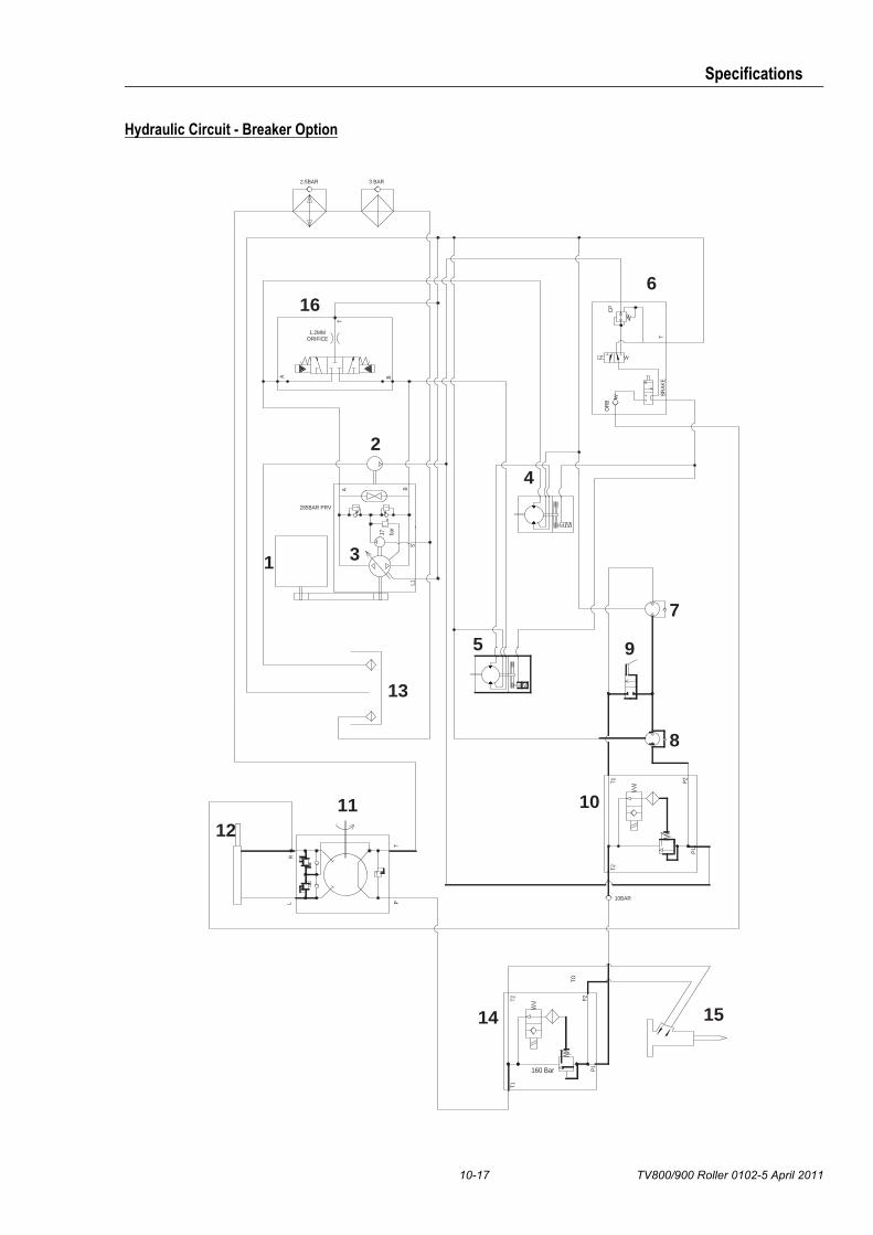
10-17 TV800/900 Roller 0102-5 April 2011
Specifications
Hydraulic Circuit - Breaker Option
ORIFICE1.2MM
160 Bar
BA
L1S
BR
AK
ET
CP
OR
B
TP
RL
P2
P1
T1T2
10BAR
285BAR PRV
P2
P1
T2T1
TO
2.5BAR 3 BAR
B
T
A
bar
17
16
2
1 3
6
4
7
5
13
9
8
101112
14 15

Specifications
TV800/900 Roller 0102-5 April 2011 10-18
Torque Figures
The tightening torques given are for un-plated nuts and bolts. As finish and lubrication materially affect tightening torque byincreasing or decreasing friction, it is necessary to apply correction factors to achieve the required bolt loading when one or bothcomponents are plated.
Nut Finish = 8mm Self Colour
Bolt Finish = 8mm 8.8 Grade Cadmium
Correct Tightening Torque = 23.5 x 0.8 = 18.8 Nm
Standard Nut and Bolt Torque Figures - Nm
Material Grade ISO
Dia. (mm) / Pitch 8.8 10.9 12.9
8 / 1.25 23.5 33 39
10 / 1.25 46.8 65.8 79
12 / 1.75 87.7 132 147.8
14 / 2.0 131.5 185 222
16 / 2.0 206 290 348
18 / 2.5 253 355 426
20 / 2.5 402 566 678
Correction Factors for Plate Finishes
Finish Correction Factor
Self Colour 1.0 1.0 0.8
Zinc 1.15 1.2 1.35
Cadmium 0.85 0.9 1.2
Durlock Unit Torque Figures - Nm
Material Grade ISO
Dia. (mm) / Pitch 12.9
8 / 1.25 39
10 / 1.25 79
12 / 1.75 147.8
14 / 2.0 222
16 / 2.0 348
20 / 2.5 678