calorillleters for heat of solution and low-temperature … for heat of solution and low-temperature...
TRANSCRIPT
Calorillleters for Heat of Solution and Low-Temperature
Heat Capacity Measurements
GEOLOGICAL SURVEY PROFESSIONAL PAPER 755

Calorimeters for Heat of Solution and Low-Temperature
Heat Capacity Measurements By RICHARD A. ROBIE and BRUCE S. HEMINGWAY
GEOLOGICAL SURVEY PROFESSIONAL PAPER 755
A description of the construction and operation of a calorimeter for determining the heats of solution in aqueous HF or HCl and of a low-temperature heat capacity calorimeter for cp measurements between 10 and 380 kelvin
UNITED STATES GOVERNMENT PRINTING OFFICE, WASHINGTON 1972

UNITED STATES DEPARTM.ENT OF THE INTERIOR
ROGERS C. B. MORTON, Secretary
GEOLOGICAL SURVEY
V. E. McKelvey, Director
Library of Congress catalog-card No. 72-600115
For sale by the Superintendent of Documents, U.S. Government Printing Office Washington, D.C. 20402 - Price 40 cents
Stock Number 2401-2182.

CONTENTS
Abstract ___________________________________________ _ Introduction ________________________________________ _ Acknowledgments ___________________________________ _
Low-temperature heat capacity calorimeter _____________ _ Cryostat components ____________________________ _
Submarine _________________________________ _ Electrical lead wires _________________________ _ Heat station ________________________________ _ Helium reservoir ____________________________ _ Isothermal shield ____________________________ _ Helium economizer __________________________ _ Floating ring _______________________________ _ Vacuum elevator and heat switch _____________ _ Adiabatic shield _____________________________ _ Calorimeter ________________________________ _ Thermometer _______________________________ _ Heater _____________________________________ _ Cryostat hoist_ _____________________________ _
Vacuum systems ________________________________ _ Adiabatic shield controller ________________________ _ Assembly ______________________________________ _
Temperature-energy measurements circuit_ _________ _ Operation and data reduction _____________________ _
Heat capacity results for Calorimetry Conference benzoic acid _____________________________________________ _
Page
1 1 2 3 3 3 4 4 4 4 4 4 4 4 4 4 7 7 7 7 9 9
11
13
Heat of solution calorimeter __________________________ _ Components ____________________________________ _
Submarine _________________________________ _ Calorimeter vesseL __________________________ _ Calorimeter top and closure seal ______________ _ Thermometer _______________________________ _ Heater _____________________________________ _
Stirrer shaft and motor drive _________________ _ Puncture tube ______________________________ _ Sample holder and impeller assembly __________ _ Calorimeter support connecter ________________ _
Operation and data reduction _____________________ _ Corrections _________________________________________ _
Sources of heat exchange _________________________ _ ltadiation ______________________________________ _
Conduction through solid connections ______________ _ Conduction and convection through a gas __________ _ Corrections for heat exchange _____________________ _ Corrections for superheating of the electrical heater __
Calculation of heat of reaction ________________________ _
Heat of solution of Tris (C4HuNOa) ___________________ _
Conclusions and recommendations for future improve-ments ____________________________________________ _
References cited _____________________________________ _
ILLUSTRATIONS
Page
13 13 13 17 17 17 17 17 19 19 19 19
20 20 20 22 22 25 27
28
28
30
31
Page
FIGURE 1. Diagram showing cross section of helium cryostat for heat capacity measurements between 4 and 400 K_ _ _ _ _ _ _ _ _ _ 3 2. Cutaway drawing of sample holder and heater bobbin-thermometer assembly_ _ _ _ _ _ _ _ _ _ _ _ _ _ _ _ _ _ _ _ _ _ _ _ _ _ _ _ _ _ _ _ _ _ 6 3. Block diagram of adiabatic shield controller________________________________________________________________ 8 4. Schematic diagram showing electrical measurements circuit for calorimetry _________________ .:.___________________ 10 5. Temperature-time curve for a heat capacity measurement_ _________ .__________________________________________ 12 6. Deviation plot of Cp for Calorimetry Conference sample of benzoic acid_______________________________________ 14 7. Deviation plot of U.S. Geological Survey measurements of the Cp of the Calorimetry Conference sample of benzoic
acid_______________________________________________________________________________________________ 16 8. Cross section of HF solution calorimeter___________________________________________________________________ 18 9. Drawing of sample holder and loading pedestaL____________________________________________________________ 20
10. Temperature-time curve for the heat of solution of 4.6 g of hydromagnesite in 4 N HCL _ _ _ _ _ _ _ _ _ _ _ _ _ _ _ _ _ _ _ _ _ _ _ _ 21 11. Coding sheet for heat of solution experiment_______________________________________________________________ 24 12. Graph showing heat of solution of Standard Reference Material724, Tris, between 25° and 35°C_________________ 29
TABLES
Page
TABLE 1. Time-voltage log of the heat capacity measurement shown in figure 5------------------------------------------ 12 2. Least squares values for the heat capacity of the Calorimetry Conference sample of benzoic acid___________________ 15 3. Observed heat capacities of Calorimetry Conference sample of benzoic acid_____________________________________ 15
III

IV CONTENTS
Page TABLE 4. Printout of computer reduction____________________________________________________________________________ 22
5. Fortran IV-G computer program for reducing heat of solution data ________________________ ---_- __ ------------- 23 6. Thermal and electrical constants of solution calorimeter at 30°C_______________________________________________ 25 7. Heat of solution of Tris (C4HnN03), in 0.1 N HCL---------------------------------------------------------- 30

CALORIMETERS FOR HEAT OF SOLUTION AND LOW-TEMPERATURE HEAT CAPACITY
MEASUREMENTS
By RICHARD A. RoBIE and BRucE S. HEMINGWAY
ABSTRACT
This report describes the construction and operation of an aqueous-solution calorimeter for enthalpy of reaction measurements and a low-temperature calorimeter for measuring heat capacities between 10 and 380 K (kelvin). Heat capacity data are used to calculate the entropy from the third law of thermodynamics.
The heat capacity calorimeter is of the adiabatically shielded type and uses precooling by solid nitrogen together with the use of helium gas (for heat exchange) to reach temperatures of 52 K. Liquid helium is used as the lowest temperature refrigerant. The calorimeter, a liquid-helium reservoir, a gas heat exchanger, and an automatically controlled adiabatic shield are suspended within a cryogenic vacuum submarine. The submarine is sealed with reusable soft aluminum gaskets and is supported within an 18.6-liter metal Dewar flask. The operation of the calorimeter was tested by measuring the heat capacity of the Calorimetry Conference benzoic acid sample. Our results, between 29 and 300 K, are within 0.15 percent of the values obtained by six previous investigations on this same material.
The vacuum-jacketed aqueous-solution calorimeter for heat of solution measurements in strong acids, including HF, is made of gold-plated copper and has a copper resistance thermometer wound on its outer surface, an internal heater, and a combined sample holder-stirrer. It may be operated either at constant pressure to obtain the enthalpy change, llH, or at a constant volume to obtain the change in the internal energy, !!U, at temperatures up to 100°C. It has a temperature sensitivity of ±0.00005°C. Heats of solution as small as 4 calories have been determined with a precision of ±0.05 cal.
Our result for the heat of solution of U.S. National Bureau of Standards Standard Reference Material 724, Tris, C4HuNOa, in 0.1 N HCl at 25°C is:
!lH = -7098.0±11 cal mole-1
The temperature coefficient of the solution reaction is
d!!H I dT = 42.7 cal mole-1 degree-1
This value was obtained from 20 separate heat of solution measurements between 24 o and 36°C. The operation and methods of data reduction for these two calorimeters are discussed.
INTRODUCTION
In recent years earth scientists have become more aware of the usefulness of thermodynamic methods, and there has been an increasing demand for free-
energy data for minerals. Unfortunately there has not been an equivalent increase in the number of calorimetric studies of minerals, the principal source of freeenergy values. In the hope that we might attract others into the "business," we present a description of the construction and operation of two calorimeters used in laboratories of the U.S. Geological Survey for determining the enthalpy of formation, AH" and "Third Law" entropies, S, of minerals. These are a solution calorimeter for measuring heats of reaction and a heat capacity calorimeter capable of precise measurements in the range of 10 to 380,K (kelvin).
The Gibbs free energy of formation, AG" is probably the single most useful thermodynamic property of a phase inasmuch as it provides a direct measure of the chemical stability of that phase. The Gibbs free energy of a phase may be determined from equilibrium data such as aqueous solubility and cell voltage or by calorimetric techniques from the relation
(1)
where AH1 is the enthalpy of formation and AS is the entropy change.
Since the work of Julius Thomsen and Marcellin Berthelot in the 1880's, aqueous-solution calorimetry has been, and remains so today, the single most important technique for the precise determination of the heats of formation and reaction involving complex inorganic materials.
The molar heat capacity at constant pressure, Cp, is the amount of heat necessary to raise the temperature of 1 formula weight (mole) of a material by 1 degree. The heat capacity is a function of temperature and goes to zero as the temperature approaches 0 K. Accurate heat capacity data permit calculation of the temperature coefficient of the enthalpy of a chemical reaction or of a phase transition from the relation:
(2)
The most important use for low-temperature Cp data
1

2 CALORIMETERS, HEAT OF SOLUTION AND LOW-TEMPERATURE HEAT CAPACITY MEASUREMENTS
is, however, for determining the entropy, ST, utilizing the third law of thermodynamics:
ST=So+ J.Tcp;T dT. (3)
In relation 3, So is the entropy at 0 K, and for an ordered substance (that is, one which is in a state of internal equilibrium) So is zero.
Besides its use for calculating Gibbs free energies from relation 1, the entropy can be used, together with the molar volume, V, to calculate the temperaturepressure variation of a chemical equilibrium from the Clapeyron equation,
dP AS dT= AV. (4)
For a solid the entropy at 298.15 K (25.0°C) is usually obtained from heat capacity measurements made from low temperatures ( :::;20 K) to above room temperature. If no anomalies exist below the lowest temperature at which CP is measured, entropies, accurate to 0.1 to 0.2 percent, are readily obtained using modern calorimetric techniques. Precise measurements of heat capacities at low temperatures began with the work of W. F. Giauque and his students in the 1920's (for example, Gibson and Giauque, 1923). These studies provided a most elegant experimental confirmation of the third law of thermodynamics.
Two types of calorimeters are in common use for the determination of heat capacities at .}ow temperatures. These are the isoperibol (commonly called "isothermal" but meaning constant-temperature environment, Kubaschewski and Hultgren, 1962) and the adiabatically shielded calorimeter; in this latter type the calorimeter surroundings are continuously maintained at very nearly the same temperature as the calorimeter.
The design and operation of isoperibol-type calorimeters has been described by Giauque and Egan (1937) and by Cole, Hutchens, Robie, and Stout (1960). Adiabatically shielded calorimeters have been described by Southard and Andrews (1930), Scott, Meyers, Rands, Brickwedde, and Bekkedahl (1945), and Westrum (1962). Westrum, Furukawa, and McCullough (1968) have presented a comprehensive review of design and operation of adiabatic calorimeters.
In designing calorimeters for either heat of solution or heat capacity measurements the following general requirements were considered: 1. Minimal heat leak. 2. Fast response to temperature changes. 3. Calorimeter should contribute only a small fraction
of the total heat capacity (calorimeter+solvent, or sample) measured.
4. Sensitivity of 0.01 percent. 5. Simplicity of operation and data reduction. 6. Provision for eventual automatic data reduction. The additional specific requirements for the solution calorimeter were: 1. Inertness to the widest variety of inorganic solvents
including HF. 2. Operable between oo and 150°C. 3. Provision for rapid cooling without disturbing the
calorimetric solvent. 4. The use of gold plating instead of solid noble metal
parts. 5. Constant pressure and (or) constant volume opera
tion (gas is evolved in the solution of carbonates or sulfides, and it is then preferable to operate with the calorimeter sealed).
The design requirements that we felt were desirable for a low-temperature heat capacity calorimeter include: 1. Use of liquid helium as the lowest temperature
refrigerant for safety reasons. 2. Ability to precool the calorimeter to near 50 K to
economize on the amount of liquid helium used. 3. Use of automatic regulation for temperature control
of the adiabatic shield. A solution calorimeter which satisfied most of the
above requirements was described by Robie (1965). Six years experience with this calorimeter (W aldbaum and Robie, 1966, 1972), including measurements with 10 N HF at 70°C and 4 N HCl at 30°C and 3.5 atmospheres C02 pressure, suggested a number of improvements in the design, operation, and methods of data reduction which have been incorporated in the aparatus described in this report.
A first version of the cryostat 1 used for the lowtemperature heat capacity measurements was built in 1959. The basic geometry of the cryostat is similar to one described by Morrison and Los (1950).
ACKNOWLEDGMENTS
We wish to express our appreciation to Rudolph Raspet, Raymond Trulli, W. H. Wilson, and Alex Herold, of the U.S. Geological Survey, and to Ralph Orwick, U.S. National Bureau of Standards, for help in the construction of the two calorimeters. We are also much indebted to Prof. Edgar F. Westrum, Jr., and Dr. Bruce D. Justice, Department of Chemistry, University of Michigan, for providing us with the
1 A cryostat is a device used for maintaining and controlling temperatures below 0°C. In this report we shall frequently use the abbreviations LN 2 and LHe to mean liquid nitrogen and liquid helium, respectively. LN2 boils at 77.3 K and LHe boils at 4.2 K.

LOW TEMPERATURE HEAT CAPACITY CALORIMETER 3
Fortran IV orthogonal polynomial curve fitting routine used at the Thermochemistry Laboratory of the University of Michigan, and to Walter Anderson of the U.S. Geological Survey for writing an early version of the X-Y plotter program. We thank Dr. D. W. Osborne and Prof. Edgar F. Westrum, Jr., for making their unpublished results on benzoic acid available to us. Dr. Stewart Gunn (University of California Lawrence Radiation Laboratory) called our attention to the transitions in Teflon near 25°C which had caused us many inexplicable problems prior to his help. The work described in this report was supported in part by National Aeronautics and Space Administration (NASA) contract T-75405. One of us (Hemingway) wishes to thank the National Science Foundation for partial support under grant G .A. 1651.
LOW-TEMPERATURE HEAT CAPACITY CALORIMETER
The calorimeter cryostat is shown in figure 1. The outer part of the cryostat is a commercial 0-ring flanged stainless steel Dewar flask (Minnesota Valley Engineering-F2A) 2 of 18.7 centimeters inside diameter, 76 em internal depth, and 18.6 liter capacity (h). It is equipped with a Richards-type valve (Scott, 1959, p.182) for reevacuation if necessary. The upper plate of the cryostat seals against the 0-ring in the Dewar flange. This permits evacuation of the space over the LN 2 and eliminates the large outer jacket common to immersion-type cryostats operating below 77 K, such as those described by Giauque and Egan (1937), Cole, Hutchens, Robie, and Stout (1960), and Sterrett, Blackburn, Bestul, Chang, and Horman (1965).
CRYOSTAT COMPONENTS
SUBMARINE
A vacuum submarine ( m) is supported within the Dewar by a thin-walled (0.064 em) stainless steel tube and is attached to a high-vacuum system by a rotatable 0-ring flange (d). The submarine is constructed of
2 Reference to specific manufacturers and model numbers is made to facilitate understanding and does not imply endorsement by the U.S. Geological Survey.
FIGURE 1.-Cross section of helium cryostat for heat capacity measurements between 10 and 380 K. a,Twenty-eight pin electrical feed through, with protective aluminum cap; b, vacuum elevator for mechanical heat switch; c, connection for cryogenic vacuum pump; d, flange to vacuum system; e, filling tube for LN2;/, helium gas vent; g, filling tube for LHe; h, 0-ring flanged Dewar flask; i, aluminum gasket; j, copper heat station; k, electrical standoffs; l, helium economizer; m, cryogenic vacuum submarine; n, LHe reservoir; o, mechanical heat switch; p, floating ring; q, adiabatic shield; r, platinum resistance thermometer; s, heater-thermometer bobbin; t, calorimeter (sample container); u, isothermal shield.
type 304 stainless steel, and all joints are fusion heliarc welded without the addition of filler rod using the
(J) 0:: LLJ 1-
~ i= z LLJ (.)
~
!:e
'<t ;:!;
~
8
ID
'<t 0
N
0
a
b
c
d
e
f
g
h
j
k
m
n
0
p
q
r 8
t
u

4 CALORIMETERS, HEAT OF SOLUTION AND LOW-TEMPERATURE HEAT CAPACITY MEASUREMENTS
techniques of R. R. Orwick (U.S. National Bureau of Standards, 1968). It is 40.6 em deep, 13.97 em in diameter, and has a wall thickness of 0.13 em. The inner surface is nickel plated. The submarine is sealed with eight )i -20 bolts which compress an annealed aluminum gasket (i) against knife edges machined into the ·surfaces of the closure flanges. The knife-edge seal has proved to be highly reliable and will sustain a vacuum of 10-7 torr at 50 K. 3 To minimize heat transfer to the calorimeter by gaseous conduction and convection, the inside of the submarine is maintained at a pressure of 10-6 torr. Heat exchange by radiation is minimized by plating all metallic surfaces within the submarine with either nickel or gold (emissivity ~0.03). A reservoir for LHe, a gas heat exchanger, the sample container (calorimeter), and its associated isothermal and adiabatic shields are supported within the submarine.
ELECTRICAL LEAD WIRES
Twenty-eight wires (25 copper and three constantan) enter the cryostat through a tubular multiheader connecter (a). A heavy walled aluminum cap covers the electrical junction. The copper leads, No. 32 American Wire Gage (Nylclad insulated) and No. 32 A WG constantan (double Formvar insulated), are wound into the grooves of a 28-lead screw thread (0.025 em deep) machined into the outer surface of the heat station (j) and are soldered to metal-ceramic electrical standoffs (Latronics 95 :0034) at the base (k) of the heat station.
HEAT STATION
The heat station (j), whose upper surface is in direct contact with the refrigerant in the Dewar flask, is a copper ring, welded to the top plate of the submarine. Its functions are to bring the electrical lead wires (at room temperature) to the temperature of the bath (LN 2) and thus minimize the heat conducted to the helium reservoir and to provide an isothermal junction for connecting the smaller diameter wires (No. 36 AWG) which pass to the helium economizer, helium reservoir, floating ring, adiabatic shield, and finally the calorimeter. Fifty centimeters of each wire is wound onto the heat station and cemented in place with a thermosetting, polyvinyl phenolic varnish (General Electric-7031 glyptal); the varnish is baked at 150°C for 2 hours. Scott (1959, p. 127) has shown that this length of contact should bring the wire temper-
8 We have found that by coating the metal gaskets with a thin film of stopcock grease they can be reused as many as five times. In an earlier version of this cryostat· we used the solder cup joint described by Giauque and Egan (1937). This was later modified to use a commercial Teflon-coated metallic V-ring seal. Although both of these seals worked adequately, they are neither as reliable nor as convenient as the soft aluminum seal used in our present cryostat.
ature to within 0.5 K of the heat-station temperature. Ginnings· and West (1968) gave a rigorous heat-flow analysis of the problem of heat-stationing electrical lead wires in calorimetry. At the heat station the wires are soldered to electrically insulated terminals. Smaller gage wires (No. 36 AWG) are also soldered to these terminals and are wound into the grooves of a 28-lead screw thread cut into the outer surfaces of the helium economizer (l), helium reservoir (n), and the floating ring (p). From the floating ring the wires pass to the adiabatic shield (q) to which they are similarly thermally anchored and thence to the calorimeter (t).
HELIUM RESERVOIR
The LHe reservoir (n) is constructed of copper. It has an external diameter of 12.7 em, a depth of 14.0 em, and a wall thickness of 0.11 em. A 28-lead screw thread (one turn in 5 em by 0.025 em deep) is cut into the outer surface of the helium reservoir. Both the helium reservoir and economizer have a nickel-plated surface 0.0002 em thick. Twenty-five copper and three constantan wires are wound into these grooves on the outer surface of the economizer and helium reservoir and on the floating ring, and are cemented into place with GE-7031 baked at 150°C for 2 hours. The LHe reservoir has a capacity of 1,500 cm3• It is connected to the top of the cryostat and to the helium economizer through thin-walled (0.05 em) stainless steel (type 304) tubes. A 200-ohm resistance heater is wound about the lower one-fourth of the helium reservoir to permit rapid warmup when necessary.
ISOTHERMAL SHIELD
An isothermal shield ( u) is attached to the base of the helium reservoir and entirely surrounds the adiabatic shield and calorimeter. It is made of copper, is 15.24 em long, and has an inside diameter of 9.84 em. The wall thickness is 0.064 em. Both inner and outer surfaces are nickel plated. The shield is attached to the base of the helium reservoir by six 4-40 screws. A thin film of stopcock grease (Apiezon T) is used to improve thermal c·ontact between the mating surfaces.
HELIUM ECONOMIZER
The effluent gas from the LHe reservoir (n) exits through a 10-plate heat exchanger (l), the purpose of which is to increase the refrigeration efficiency of the LHe by utilizing the high heat capacity of the helium gas to precool the electrical lead wires wound on the outer surface of the exchanger, before they reach the reservoir. Its design follows that of Westrum (1962).
FLOATING RING
A copper" floating ring" (p) is suspended immediately

CRYOSTAT COMPONENTS 5
beneath the LHe reservoir by three nylon rods (0.5 em diameter and 3.2 em long). The electrical lead wires from the helium reservoir are wound into grooves on the outer surface of the ring and are thermally anchored to the ring with GE-7031 varnish baked at 150°C. The function of the ring is to bring the electrical leads to a temperature intermediate between that of the LHe reservoir and the adiabatic shield. Twentyone metal-ceramic electrical terminals are soldered to the base of the ring to provide isothermal junctions for connecting the wires from the adiabatic shield. A 100- : ohm heater and one junction of a differential thermocouple are also attached to this tempering ring. The other end of the thermocouple is attached to the adiabatic shield. A controller, similar to that used with the adiabatic shield, is used to maintain any desired temperature differential between the floating ring and the shield.
VACUUM ELEVATOR AND HEAT SWITCH
The calorimeter is supported by a nylon line from the vacuum elevator. A modified commercial vacuum rotary feed through (b) (National Research Corp. 1301) is used to raise or lower the calorimeter. In the fully raised position the conical closure plug at the top of the calorimeter meshes with a mating cone at the top of the adiabatic shield, which in turn contacts a mating conical surface (mechanical heat switch) at the base of the LHe reservoir (n). This permits the calorimeter and adiabatic shield to be cooled by conduction to the temperature of the LHe reservoir while operating in a high vacuum. After the calorimeter and adiabatic shield have cooled to below 10 K, the rotation of the winch (b) is reversed, thus separating them from thermal contact.
To maximize heat transfer, the conical surfaces of the heat switch were lapped together prior to plating in order to maximize the surface contact area. About 3 hours is required to cool the calorimeter and shield from 52 to '4.2 K~
ADIABATIC SHIELD
The adiabatic shield (q) is supported by three nylon lines immediately beneath the floating ring (p). It completely surrounds the calorimeter (t), and is in turn surrounded by the isothermal shield ( u). The function of the adiabatic shield is to enclose the calorimeter (sample holder) with a surface of uniform temperature which can be continuously maintained at the same temperature as the sample holder. When this condition is satisfied, t::.T is zero and there is no heat exchange between·the calorimeter and. its surroundings.
The adiabatic shield is constructed of copper and is made in three parts, top, bottom, and side. A double
lead screw thread is machined into the outer surface of each part and both inside and outside surfaces are gold plated (0.0005 em thick). No. 30 AWG Lohm wire (W. B. Driver Co., double fiber-glass insulated) is wound noninductively into the thread grooves on each section of the shield to serve as heaters. The resistance of each of the three heater sections is, within about 10 percent, in the same ratio as the mass of each part, and accordingly, thermal gradients between the three parts of the shield should be negligible. The heaters are connected in series, and only a single differential thermocouple is used to control the shield-calorimeter temperature difference. The electrical lead wires to the calorimeter are recessed into a deeper set of 20 grooves beneath the heater windings to equilibrate them thermally with the adiabatic shield.
CALORIMETER
The calorimeter (t) used in the present investigation was machined from copper rod. It· has an outside diameter of 4.76 em, a depth of 7.62 em, and a wall thickness of 0.038 em. The end caps are 0.064 em thick. The outside surface is electroplated with gold 0.0005 em thick. The complete calorimeter assembly is shown in figure 2. Four 0.038-cm-thick fins are silver soldered axially to the central reentrant well to promote rapid temperature equilibration between the calorimeter and sample. The calorimeter is closed using a 0.95-cm-diameter tapered threaded plug (fig. 2, A) and a Teflon tape seal. A small tube (B) in the top of the calorimeter is used to replace the air in it with dry helium gas to speed up heat interchange between the sample and the calorimeter. It is sealed with a small amount of soft solder. The empty calorimeter, including thermometer (F) and heater bobbin (E), weighs 157.0 grams and has an internal volume of 117.1 cm3•
THERMOMETER
Temperatures are determined using a four-lead strain-free platinum resistance thermometer (Meyers, 1932), calibrated by the U.S. National Bureau of Standards. It has an ice-point resistance of 34.94 ohms and a sensitivity at ooc of 0.14 ohm degree-1
•
The original calibration was in terms of the International Practical Temperature Scale of 1948, IPTS-48 (Stimson, 1961), and the provisional U.S. National Bureau of Standards scale, NBS-55, between 10 and 90 K.
In 1968 the International Practical Temperature Scale was completely revised to bring practical temperature measurements into better agreement with the true thermodynamic temperature (Comite International des Poids et Mesures, 1969). The new scale

6 CALORIMETERS, HEAT OF SOLUTION AND LOW-TEMPERATURE HEAT CAPACITY MEASUREMENTS
B
E F
c
FIGURE 2.-Cutaway drawing of the sample holder and heater bobbin-thermometer assembly. A, Conical closure plug; B, filling tube for helium gas; C, calorimeter body; D, false bottom; E, copper heater bobbin (heater wire not shown); F, platinum resistance thermometer.
ADIABATIC SHIELD CONTROLLER 7
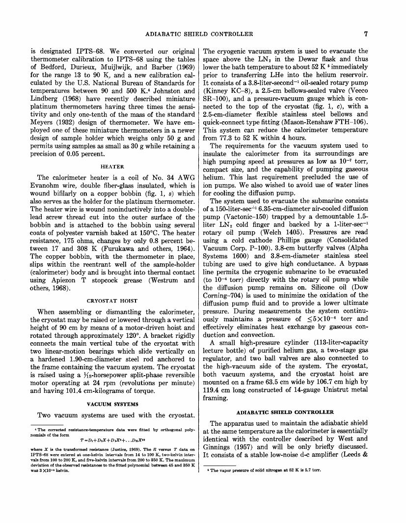
is designated IPTS-68. We converted our original thermometer calibration to IPTS-68 using the tables of Bedford, Durieux, M uijlwijk, and Barber (1969) for the range 13 to 90 K, and a new calibration calculated by the U.S. National Bureau of Standards for temperatures between 90 and 500 K. 4 Johnston and Lindberg (1968) have recently described miniature platinum thermometers having three times the sensitivity and only one-tenth of the mass of the standard Meyers (1932) design of thermometer. We have employed one of these miniature thermometers in a newer design of sample holder which weighs only 50 g and permits using samples as small as 30 g while retaining a precision of 0.05 percent.
HEATER
The calorimeter heater is a coil of No. 34 AWG Evanohm wire, double fiber-glass insulated, which is wound bifilarly on a copper bobbin (fig. 1, s) which also serves as the holder for the platinum thermometer. The heater wire is wound noninductively into a doublelead screw thread cut into the outer surface of the bobbin and is attached to the bobbin using several coats of polyester varnish baked at 150°C. The heater resistance, 175 ohms, changes by only 0.8 percent between 17 and 308 K (Furukawa and others, 1964). The copper bobbin, with the thermometer in place, slips within the reentrant well of the sample-holder (calorimeter) body and is brought into thermal contact using Apiezon T stopcock grease (Westrum and others, 1968).
CRYOSTAT HOIST
When assembling or dismantling the calorimeter, the cryostat may be raised or lowered through a vertical height of 90 em by means of a motor-driven hoist and rotated through approximately 120°. A bracket rigidly connects the main vertical tube of the cryostat with two linear-motion bearings which slide vertically on a hardened 1.90-cm-diameter steel rod anchored to the frame containing the vacuum system. The cryostat is raised using a ~{s-horsepower split-phase reversible motor operating at 24 rpm (revolutions per minute) and having 101.4 em-kilograms of torque.
VACUUM SYSTEMS
Two vacuum systems are used with the cryostat.
4 The corrected resistance-temperature data were fitted by orthogonal polynomials of the form
where X is the transformed resistance (Justice, 1969). The R versus T data on IPT8-68 were entered at one-kelvin intervals from 14 to 100 K, two-kelvin intervals from 100 to 200 K, and five-kelvin intervals from 200 to 350 K. The maximum deviation of the observed resistances to the fitted polynomial between 45 and 350 K was 3 X10⁻⁴ kelvin.
The cryogenic vacuum system is used to evacuate the space above the LN 2 in the Dewar flask and thus lower the bath temperature to about 52 K 6 immediately prior to transferring LHe into the helium reservoir. It consists of a 3.8-liter-second-1 oil-sealed rotary pump (Kinney KC-8), a 2.5-cm bellows-sealed valve (Veeco SR-100), and a pressure-vacuum gauge which is connected to the top of the cryostat (fig. 1, c), with a 2.5-cm-diameter flexible stainless steel bellows and quick-connect type fitting (Mason-Renshaw FTH-106). This system can reduce the calorimeter temperature from 77.3 to 52 K within 4 hours.
The requirements for the vacuum system used to insulate the calorimeter from its surroundings are high pumping speed at pressures as low as 10-7 torr, compact size, and the capability of pumping gaseous helium. This last requirement precluded the use of ion pumps. We also wished to avoid use of water lines for cooling the diffusion pump.
The system used to evacuate the submarine consists of a 150-liter-sec--'-1 6.35-cm-diameter air-cooled diffusion pump (Vactonic-150) trapped by a demountable 1.5-liter LN 2 cold finger and backed by a 1-liter-sec-1
rotary oil pump (Welch 1405). Pressures are read using a cold cathode Phillips gauge (Consolidated Vacuum Corp. P-100). 3.8-cm butterfly valves (Alpha Systems 1600) and 3.8-cm-diameter stainless steel tubing are used to give high conductance. A bypass line permits the cryogenic submarine to be evacuated (to 10-4 torr) directly with the rotary oil pump while the diffusion pump remains on. Silicone oil (Dow Corning-704) is used to minimize the oxidation of the diffusion pump fluid and to provide a lower ultimate pressure. During measurements the system continuously maintains a pressure of ~ 5 X 10⁻⁶ torr and effectively eliminates heat exchange by gaseous conduction and convection.
A small high-pressure cylinder (113-liter-capacity lecture bottle) of purified helium gas, a two-stage gas regulator, and two ball valves are also connected to the high-vacuum side of the system. The cryostat, both vacuum systems, and the cryostat hoist are mounted on a frame 63.5 em wide by 106.7 em high by 119.4 em long constructed of 14-gauge Unistrut metal framing.
ADIABATIC SHIELD CONTROLLER
The apparatus used to maintain the adiabatic shield at the same temperature as the calorimeter is essentially identical with the controller described by West and Ginnings (1957) and will be only briefly discussed. It consists of a stable low-noise d-e amplifier (Leeds &
6 The vapor pressure of solid nitrogen at 52 K is 5.7 torr.

8 CALORIMETERS, HEAT OF SOLUTION AND LOW-TEMPERATURE HEAT CAPACITY MEASUREMENTS
Northrup 9829), a 10-millivolt recorder (Leeds & Northrup Speedomax W) equipped with a 100-percentcontrol slide wire, a three-mode (proportional, rate, reset) current-adjusting controller (Leeds & Northrup CAT-80), and a 50-watt d-e power amplifier (HewlettPackard 6824A). Figure 3 is a block diagram of the adiabatic-shield controller.
A differential thermocouple (Au+2.1 percent Co versus Cu) senses any temperature difference between the adiabatic shield and the calorimeter. The thermocouple voltage is amplified by the d-e amplifier and is displayed on the chart recorder. Any deviation of this
D-C AMPLIFIER CHART
RECORDER
voltage from the recorder set point causes the threemode controller to put out a direct current proportional to the deviation from the set point. This current, 0-5 milliamperes, is insufficient to heat the adiabatic shield, and accordingly it is fed to the d-e power amplifier which in turn puts power into the shield heaters to reduce the temperature difference to zero. The thermocouple sensitivity is about 11 microvolts deg-1 at 10 K and 38'·JLV. deg...:i at 300 K (Fuschillo, 1957).
Inasmuch as the preamplifier has a sensitivity of 0.1 JLV, the shield controller can maintain a zero temperature difference between the calorimeter and adia-
3-MODE CONTROLLER
D-C POWER
AMPLIFIER
D _j w
D-C POWER SUPPLY
0:: w 1-w ~
0:: 0 _.J
DIFFERENTIAL THERMOCOUPLE I CJ)
w ou
<( u
---------
EXPLANATION
COPPER
--------
GOLD+ 2.1 PERCENT COBALT
-----
FIGURE 3.-Block diagram of adiabatic shield controller.
(/)~ (]) <(
D <(

TEMPERATURE-ENERGY MEASUREMENTS CIRCUIT 9
batic shield to ±0.01 o at 10 K and ±0.004° at temperatures above 50 K.
ASSEMBLY
The empty calorimeter is weighed, filled with sample ( -5+100 mesh powder), and closed using the threaded conical plug (fig. 2, A). Teflon tape, 0.007 em thick, is wrapped on the pipe threads of the closure plug to form a vacuum-tight seal. The calorimeter is weighed again and placed in a vacuum bell jar. It is evacuated to 10-6 torr and the vacuum broken to a pressure of 1 atmosphere using purified helium gas passed through an activated-charcoal trap cooled with LN 2· The bell jar is quickly removed and the helium-exchange-gas tube (fig. 2, B) immediately sealed with soft solder. The calorimeter is weighed again (to determine the mass of helium gas). The sealed calorimeter is supported within the adiabatic shield by the nylon line from the vacuum winch. The electrical leads to the platinum thermometer, the calorimeter heater, and the differential thermocouple (between the sample container and adiabatic shield) are connected at the calorimeter. The bottom of the adiabatic shield is attached and the isothermal shield is fastened to the base of the helium reservoir. The base of the submarine is attached with eight ~ -20 steel bolts.
The submarine is next lowered into the Dewar flask using the motorized hoist and the Dewar sealed to the upper flange of the cryostat.
Mter assembly, the cryostat is connected to the highvacuum system, and the rotary oil pump is turned on. After 10 minutes, the diffusion pump is turned on. Approximately 2 hours is required to evacuate the submarine to a pressure on the order of 5 Xl0-5 torr. After 24 hours of evacuation, the system reaches a limit of 8X10⁻⁷ torr.
Preliminary heat capacity measurements are made at room temperature to ensure proper operation of the apparatus. The Dewar is then filled with LN 2· At this time the valve separating the submarine and the diffusion pump is closed and helium gas at about 1 torr pressure admitted to the submarine from the helium lecture bottle. The helium gas serves to promote heat exchange between the refrigerant, LN 2, in the Dewar flask and the internal parts of the submarine. Approximately 90 min is required to cool the calorimeter, adiabatic shield, helium reservoir, economizer, and the floating ring to 77.3 K. LN 2 is then added to the Dewar, the boiloff vents sealed, the cryogenic vacuum pump turned on, and the valve to the large rotary pump opened.
Three hours of evacuation by the vacuum pump (capacity 3.8 liters sec-1) reduces the temperature within the Dewar flask to about 52 K. The valve
separating the submarine and diffusion pump is next opened and the helium exchange gas pumped out, thus thermally insulating the internal parts of the submarine, at 52 K, from their surroundings. The exchange gas can be pumped out to the order of 8Xl0-6 torr within 45 min after opening the valves. Precooling the internal components of the cryostat to 52 K rather than the usual 77.3 K results in a substantial saving in the amount of LHe used and in the time required for cooling to 4.2 K.
The helium reservoir is then filled with LHe using a vacuum-jacketed transfer tube, and the adiabatic shield and calorimeter are brought into thermal contact with the base of the helium reservoir using the vacuum winch and heat switch.
The capacity of the LHe reservoir, 1,500 cm3, is sufficient to cool the calorimeter and adiabatic shield to 4.2 K and permit approximately 7 hours of measurements before the LHe has evaporated. Immediately after filling, the helium transfer tube is removed from the cryostat, the helium filling tube (fig. 1, g) is sealed, and the exhaust vent (fig. 1, f) is connected to an oil bubbler to prevent condensation of solid air within the reservoir.
Mter the calorimeter and adiabatic shield have cooled to 10 K or lower, they are separated from thermal contact with the helium reservoir using the winch. The controllers for the adiabatic shield and the floating ring are then adjusted, and measurement of the heat capacity is begun. Between 5 and 50 K the increment of temperature rise for each measurement is made approximately 10 percent of the absolute temperaturethat is, ~T~1 kelvin at 10 K, 3 kelvins at 30 K-and above 50 K the temperature increment for each measurement is kept constant at about 5 to 7 kelvins.
TEMPERATURE-ENERGY MEASUREMENTS CIRCUIT
As part of our initial design requirements, we desired that the methods for measuring the temperature ,and energy input should be the same for both the heat capacity calorimeter and the heat of solution calorimeter. For both calorimeters, temperatures are determined using a four-lead resistance thermometer, and the energy input is by electrical heating using a four-lead resistance heater having a very small temperature coefficient of resistance. This type of arrangement allows us to determine both temperature and electrical power input from only voltage measurements by using potentiometric methods.
The measuring circuit, shown schematically in figure 4, consists of a five-position thermal-free ( ±0.01 p.V)
selector switch (Guildline 9145A), a six-dial threerange potentiometer, and a d-e chopper amplifier-null detector (Keithley 147) having a sensitivity of ±0.003

10 CALORIMETERS, HEAT OF SOLUTION AND LOW-TEMPERATURE HEAT CAPACITY MEASUREMENTS
r---- -rl I• STRIP- NULL 6-DIAL I -=->: CHART ,...--
DETECTOR POTENTIOMETER I ..:r- tO:
RECORDER L----..1 --r STAN DARD
HP 71018
...L.
KEITH LEY 147 GUI LDLINE 9160D ..:r-
DIGITAL VOLTMETER
TRIPLETT 4235-F
I
SWITCH GUILDLINE 9145A r--------------------, ·~ : I I I I I I I I
: ~~~ ~~~~;-~ L~----r-- r--- ------~
AAlAAAAA. -v v v-v v v vv
500 49500 n n
CELL INC LOSURE GUILD LIN E M2A
1.0 .Q GUILDLINE 9330 -'\1"..-A
100.0 n
,---___:r-____ .,.AVA"vA~ GUI LDLINE v v 9330 RELAY PB JMI 105-13
r -------.. _ -------
CONSTANT VOLTAGE
POWER SUPPLY
NORTH HILLS TC 602 CR V.v.vY
EVAN OHM HEATER
--------------l----1-----------------------r----l----- --- J
V.v.vY PLATINUM
RESISTANCE THERMOMETER
FIGURE 4.-Electrical measurements circuit for calorimetry.

OPERATION AND DATA REDUCTION 11
JJ.V with less than 0.002 JJ.V hour-I drift. The potentiometer (Guildline 9160D) has a range of 0.01 JJ.V to 2.11 v and a linearity of 0.0005 percent.
The 1-v full-scale output of the null detector passes through a filter-attenuator network and is displayed on a 25-cm-strip-chart recorder (Hewlett-Packard 7101B) with half-scale sensitivity of 1 or 10 JJ.V. The null-detector chart recorder was calibrated using the 0.1-JJ.v steps of the potentiometer, and the calibration is incorporated into the computer program used to reduce the data. The unattenuated output of the null detector is simultaneously displayed on a digital voltmeter (Triplett 4235-F). The noise level of the system is ±0.02 JJ.V.
Times are recorded from a digital clock. The coil of a mercury-wetted contact relay (Potter-Bromfield JM1 105-13) is connected in series with the input trigger of a six-digit universal counter and 6-v battery. The relay has a closure time of 0.004 sec and is assumed to be the same on opening. Elapsed times for the energy input (300 to 1,000 sec) are read to 0.001 sec from the counter and should be correct to ±0.002 percent. The wires supplying current to the thermometer are connected in series with either 12.4- or 18.6-v direct current (Willard DD5-3 batteries), a 6,140- or 9,100-ohm fixed resistor of very small temperature coefficient, and a 100-ohm standard resistor (Guildline 9330). The function of the large series resistor is to provide a quasiconstant current for the platinum or copper resistance thermometer. The batteries and the 6,140- or 9,100-ohm resistor are enclosed in a thermally insulated and electrically shielded box.
The current leads of the heater are series connected to a d-e power supply (0.001 percent stability) and a 1.0-ohm standard resistor (Guildline 9330). The potential drop across the heater is attenuated by a 100 :1 voltage divider before being read on the potentiometer. The potential drop across the 1.0- and 100.0-ohm standard resistors and the voltage across the resistance thermometer are read directly on the potentiometer without attenuation. The four sets of voltage leads are connected to the five positions of the selector switch which permits any of the four voltages to be connected across the potentiometer. The fifth position, Vo, is shorted by a copper bar and provides a measure of the electrical zero of the measuring circuit.
If we call the voltage across the 100-ohm resistor VI, across the platinum (or copper) thermometer v2, across the 1.0-ohm resistor V3, and across the voltage-divider tap v 4 and the resistance of the calibrated shunts (standard resistors) R10o and RI, then the current through the thermometer is
ltherm =vdRioo amps (5)
and the thermometer resistance is
Rtherm = (v2. Rioo) /VI ohms. (6)
The current through the heater is
lhtr = (v3/R1)- (v4/500.0) amps (7)
where 500.0 ohms is the resistance of the voltagedivider tap. The term v 4/500.0 is the parallel current through the voltage divider. The voltage drop across the calorimeter heater is
Vhtr =V4(v.d.f.) volts (8)
where v.d.f. is the voltage divider factor. The electrical energy supplied to the calorimeter
heater is
(9)
Because of the constancy of the power supply and the very low temperature coefficient of resistance for the Evanohm heater wire, the integral in equation 9 can be replaced by
(10)
where the barred quantities are the mean values of the heater voltage and current and t1 -ti is the elapsed time of power input. The elapsed time is obtained from the time .. interval meter reading directly to 0.001 sec.
OPERATION AND DATA REDUCTION
The heat capacity of a material is determined by measuring the energy necessary to raise the temperature of the substance by a certain number of degrees. An example of a temperature-time curve for a typical heat capacity measurement is shown in figure 5. The time-voltage log of the heat capacity run shown in figure 5 is listed in table 1. These data are read directly from the recorder trace, which provides a permanent record of the run, and are transferred to coding sheets prior to computer processing. The sample identification, number of measurements, sample mass, gram formula weight, and the difference in weights for the helium exchange gas, stopcock grease, and Teflon tape between the filled and empty sample holder are entered on the first two lines of the code sheets. The data on the code sheets may be converted to punched cards for batch processing or entered directly into a time-sharing computer using a remote terminal.
During the time periods labeled "fore rating" or "after rating" (fig. 5), the change of temperature with time, dT I dt, is on the order of 10-4 deg min-1• The te1nperature rise, corrected for heat exchange, is obtained by extrapolating the fore- and after-period temperatures to the midtime of the energy-input period.

12 CALORIMETERS, HEAT OF SOLUTION AND LOW-TEMPERATURE HEAT CAPACITY MEASUREMENTS
U)
z >s2 _j w ~
z wsl 0:::: :::> I-<(
~60 o_ ~ w I-
FORE RATING
I ~HEATING
581800 1810 1820
TIME
AFTER RATING
1850
FIGURE 5.-Temperature-time curve for a heat capacity measurement. The calorimeter was filled with 83.96 g of benzoic acid.
TABLE 1.-Time-voltage log of the heat capacity measurement shown in figure 5
[The switch positions 0 through 4 correspond to the voltages across the shorted electrical circuit, the thermometer current shunt, the resistance thermometer the heater current shunt, and the heater voltage divider, respectively) '
Time Switch Potentiometer Null
hr min position dial setting detef't.or
(v) (J,iv)
Fore-rating period
18 2 0 0.000000 -0.005 4 1 .205850 .150 6 2 .078220 .470 8 2 .078220 .460
18 10 2 .078220 .450 12 2 .078220 .440 14 2 .078220 .430 16 0 .000000 -.030 18 1 .205850 .085
18 20 2 .078220 .400
Heating period 1
21 3 0.535000 8.20 22 3 .535000 5.80 23 4 .932360 5.50 24 4 .932360 3.90 25 3 .535000 -2.00 26 3 ;535000 -4.45 27 4 .932360 -5.35 28 4 .932360 -8.00
After-rating period
18 30 0 0.000000 -0.010 32 1 .205825 .350 34 2 .091515 .580 36 2 .091515 .565 38 2 .091515 .550
18 40 2 .091515 .535 42 2 .091515 .520 44 2 .091515 .505 46 1 .205825 .310 48 0 .000000 -.030
1 Power turned on at beginning and off at end of this period. Elapsed heating time, 480.029 sec.
Stout (1968) gave a complete discussion of the calculations and general problems of correcting for heat exchange in low-temperature calorimeters. On page 25, we discuss in detail the sources of heat exchange and methods of correction for a solution calorimeter; since most of the development is directly applicable to the low-temperature measurements, we will defer further discussion of heat exchange until the later section.
A computer program converts the raw data, table 1, into resistances and energies using equations 5 through 10. The method of converting the resistances to temperatures depends upon the temperature range. Below 45 K, temperatures are obtained from a stored resistance-temperature table by Lagrangian interpolation. Above 45 K, the polynomial expression (footnote 4, p. 7) is used to calculate the temperature.
During measurements the pressure on the solid sample in the calorimeter changes from 1 atmosphere at 300 K to 0.03 atmosphere at 10 K. The ~(pV) term for the sample is therefore negligible, and we may write
Ej~Tcorr =~Hj ~Tcorr (11)
where E is the electrical energy introduced into the sample container and ~H is the enthalpy change.
The heat capacity differences for the helium exchange gas, soft solder, and Teflon tape seal are now subtracted from ~HI ~Tcorr· The heat capacity at constant volume, Cv, of the helium is assumed to be independent of temperature and to have the value 0.744 cal g-K-1
(Guereca and others, 1967). The soft-solder difference correction is made using the heat capacities for tin and lead given by Hultgren, Orr, Anderson, and Kelley (1963). The correction for the stopcock grease is made using the heat capacity data on Apiezon T of E. F. Westrum, Jr. (written commun., Jan. 16, 1970), and that for Teflon tape from the data of Furukawa, McCoskey, and King (1952).
Below 35 K, the observed ~HI ~T values are corrected for curvature using the relation
c. =dHjdT~tJ.H/ t;T -tJ.'H/ aT{ 1:). . . (12)
where ~2H/ ~T2 is the second difference of the observed ~HI ~T versus T curve (Osborne and others, 1925). Higher power terms are negligible.
The heat capacity of the empty calorimeter is next subtracted from ~H/~Tsample+container and the result multiplied by the factor (formula weight/sample mass) to give molal heat capacities.
Orthogonal polynomials (Justice, 1969) are then used to generate a least squares fit to the molarheat capacity data and obtain a smooth table of Cp versus temperature. Curve fitting is usually done in two parts

HEAT OF SOLUTION CALORIMETER 13
with a 10 kelvin overlap near that temperature at which the fUrvature of the heat capacity, d2CpjdT2,
changes sign. The experimental data are plotted on an 80-cm-wide X-Yplotter (Calcomp 763). This eliminates the tedium of hand plotting while retaining the accuracy (±0.006 em) of manual methods. A separate computer program uses the smoothed molarCP values to calculate the thermodynamic functions Sr, (Hr-Ho/T), and (Gr- H o) /T at integral values of the kelvin temperature between 0 and 350 K.
HEAT CAPACITY RESULTS FOR CALORIMETRY CONFERENCE BENZOIC ACID
At the request of the 1948 Calorimetry Conference, the U.S. National Bureau of Standards prepared uniform samples of a-Al20 3 (corundum), n-heptane (CHa(CH2)6CHa), and benzoic acid (C 6HsCOOH) for the intercomparison of low-temperature heat capacity calorimeters. Benzoic acid has a high specific heat at low temperatures and is also used as a standard for acidimetry and for combustion calorimetry. Furukawa, McCoskey, and King (1951), Busey (1955), Osborne, Westrum, and Lohr (1955), Cole, Hutchens, Robie, and Stout (1960), Taylor and Smith (1962), E. F. Westrum, Jr. (written commun., 1970), and D. W. Osborne (written commun., 1970) have made measurements on the Calorimetry Conference benzoic acid sample using both adiabatically shielded and isothermal-type calorimeters. To check the performance of our calorimeter, we have measured the heat capacity of the Calorimetry Conference benzoic acid sample between 25 and 305 K. During the measurements, the calorimeter contained 83.960 g of sample. The weight of the empty calorimeter was 143.072 g. The sample accounted for 7 4 percent of the total observed heat capacity at 35 K and 65 percent at 300 K.
Unfortunately, neither the Calorimetry Conference nor the U.S. National Bureau of Standards has yet reported recommended values for this material. In order to provide a best value curve for comparison with our results, we statistically smoothed the data of Furukawa, McCoskey, and King (1951), Busey (1955), Osborne, Westrum, and Lohr (1955), D. W. Osborne (written commun., 1970), Cole, Hutchens, Robie, and Stout (1960), and E. F. Westrum, Jr. (written commun., 1970) using orthogonal polynomial curve fitting (Justice, 1969). This was done in two parts with a 10 kelvin overlap at 45 K. In the smoothing, each point was given equal weight, and no attempt was made to correct all the data to the same temperature scale. The correct statistical treatment would have included weighing each of the data in proportion to the sensitivity of the thermometer used and also to the ratio Cp sample/Cp sample+container· These data were not avail-
able for each set of measurements. Results for the molar heat capacity of the Calorimetry Conference sample of benzoic acid are shown in the form of the deviations, Cp(observed) -Cp(smooth), as a function of temperature in figure 6. The values of Cp from the least squares fit are given in table 2.
Our measurements on this sample on the temperature scale IPTS-48/NBS-55, with 0°C =273.15 K, are listed in chronological order of measurement in table 3 and are shown in a deviation plot in figure 7. The right-hand column of this table gives the deviation of our experimental observations from those of the best fit curve, table 2. With the exception of two points, our data are within 0.13 percent of the least squares curve. There is some indication that our results may be systematically low by as much as 0.1 percent at temperatures above 250 K.
The benzoic acid data were also calculated using the IPTS-68 scale. As was anticipated, these results differed by as much as 0.1 percent from those calculated using the IPTS-48 /NBS-55 scale, and the largest differences occurred in the temperature range where the difference in the temperature scales is changing most rapidly.
HEAT OF SOLUTION CALORIMETER
The calorimeter and submarine assembly is shown in figure 8. In this calorimeter, heat interchange is minimized by surrounding the calorimeter with a high vacuum to eliminate heat transfer by both gaseous conduction and convection, by eliminating many of the direct thermal links between the calorimeter and the bath, and by constructing those remaining links of poorly conducting materials such as Teflon or stainless steel with small cross-sectional areas. The thermal response time of the calorimeter was made short by fabricating it of copper and by having a sharp, welldefined boundary between the calorimeter and its surroundings (Sunner and Wadso, 1959).
COMPONENTS
SUBMARINE
The reaction vessel (calorimeter proper) is suspended within a vacuum jacket called a submarine (z). The submarine is rigidly supported by four 1.27 -em demountable steel rods connected at socket i in a 75-liter constant-temperature water bath (Aminco 4-1585) held to ±0.01 °C. The top of the submarine is submerged to a depth of 10 em beneath the bath surface. The submarine is made of type 304 stainless steel, and the vertical tubes containing the electrical leads ahd the connection to the vacuum system are thin-walled stainless steel to minimize surface corrosion. The inner surface of the submarine is nickel plated, 0.0013 em

0.11 1 1 1 I I I I I I I I I I I I I I 1
(/) I C;.
z ~ + w
C;. C;.
+ ~ 0 C;. I
0 C;. 0 X ..J
+
X X
xC!. X X
+ C;. 0 0 0
0 + e;.O 0 +
1 1 1 I I I I I I I I I I
+
X X
X XX
X X
XX
+ 0 0
+
<> X
+
+
<> <>
X
X X
X C;.
X
X
0 0+0 +
+ 0 0 ~ + C;. ,o.o 0
0 0
Oe;. 0
0 <>
C;.~ 0 <> X ..J C;. C;. oo 0 0 <( \0 + 0 + <> 0 u 0 <> 0 C;. z 0
+ + 0 - oO C;. <>
6 <> 0
<I
0 C;.
0 C;.
oO
C;. C;. a+-0
0
C;. <> C;.
C;.
0
C;.o 0
\ C;. 0
-1.0 percent
-0.1' I I I I I I I I I I I I I I I I I I I I I I I I I I I I I I I
0 100 200 300
TEMPERATURE, IN KELVINS
FIGURE 6.-Deviation plot of the measured values for the heat capacity of the Calorimetry Conference sample of benzoic acid. The sources of the data are as fo1lows: 0, Furukawa, McCoskey, and King (1951); b. and+, Busey (1955); X, E. F. Westrum, Jr. (written commun., 1970); 0, Cole, Hutchens, Robie, and Stout (1960); O, Osborne, Westrum, and Lohr (1955).
""""" ~
()
> t-t 0 ~
~ t:-:l t-3 t:-:l ~ sn ::t: t:-:l > t-3 0 "%.:1
U2 0 t-t q t-3 ~
0 z > z t1 t-t 0
~ t-3 t:-:l a:: 'i:l t:-:l ~ > d ~ t:-:l
::t: t:-:l > t-3
~ 'i:l > 9 t-3 ~
a:: t:-:l > U2 q ~ t:-:l a:: t:-:l
~ U2

HEAT OF SOLUTION CALORIMETER 15
TABLE 2.-Least squares values for the heat capacity of the Calorimetry Conference sample of benzoic acid
Temperature (K)
10 12 14 16 18 20 22 24 26 28
30 32 34 36 38 40 42 44 46 48
50 55 60 65 70 75 80 85 90 95
100 105 110 115 120 125 130 135 140 145
150 155 160 165 170 175 180 185 190 195
200 205 210 215 220 225 230 235 240 245
250 255 260 265 270 275 280 285 290 295
300 305
Cp (cal mole-1 K-1)
0.482 .815
1.212 1.654 2.132 2.637 3.160 3.693 4.224 4.748
5.257 5.752 6.230 6.694 7.141 7.568 7.975 8.363 8.737 9.098
9.447 10.239 10.967 11.628 12.232 12.802 13.346 13.880 14.371 14.824
15.272 15.722 16.175 16.630 17.083 17.535 17.987 18.439 18.892 19.348
19.807 20.269 20.734 21.202 21.674 22.149 22.628 23.111 23.599 24.091
24.589 25.091 25.597 26.108 26.623 27.141 27.663 28.189 28.719 29.254
29.794 30.338 30.887 31.439 31.992 32.546 33.099 33.651 34.204 34.760
35.317 35.865
Cp (joules mole-1 K -1)
2.019 3.410 5.069 6.921 8.919
11.031 13.222 15.450 17.675 19.864
21.996 24.064 26.067 28.006 29.876 31.665 33.367 34.992 36.555 38.065
39.526 42.841 45.888 48.654 51.178 53.566 55.841 58.076 60.127 62.026
63.898 65.782 67.678 69.578 71.476 73.368 75.258 77.148 79.045 80.952
82.871 84.804 86.750 88.710 90.684 92.672 94.676 96.698 98.738
100.80
102.88 104.98 107.10 109.24 111.39 113.56 115.74 117.94 120.16 122.40
124.66 126.94 129.23 131.54 133.86 136.17 138.48 140.80 143.11 145.44
147.77 150.06
TABLE 3.-0bserved heat capacities of Calorimetry Conference sample of benzoic acid
[Temperature scale is IPTS-48/NBS-55. 0°C =273.15 K. t:..Cp is the difference between our measurement values and the least square values given in table 2]
Temperature (K)
54.51 57.05 60.80 65.81
Cp (cal mole-1 K-1)
Series I
10.184 10.547 11.007 11.728
+0.006 +.002 -.002
.000
TABLE 3.-0bserved heat capacities of Calorimetry Conference sample of benzoic acid-Continued
Temperature (K)
71.74 77.87 83.59 89.26 94.91
54.57 93.53 99.23
105.18 111.14 116.90 122.45 128.05 133.70 139.21 144.57 149.92 155.39 161.10 166.88 172.94
29.11 30.93 39.44 42.34 45.14 48.17 52.07 56.38
169.27 175.44 181.84 188.20 194.53 200.83 207.10 213.50 219.92 226.30 232.75
228.97 235.42 241.83 248.48 255.45 262.28 268.99 275.58 282.06 288.43 294.68 300.84
Cp (cal mole-1 K-1)
Series 1-continued
12.424 13.105 13.744 14.312 14.704
Series II
10.543 14.704 15.214 15.748 16.285 16.806 17.310 17.821 18.325 18.825 19.313 19.804 20.306 20.817 21.379 21.941
Series III
5.025 5.493 7.485 8.039 8.583 9.125 9. 771
10.435
Series IV
21.585 22.179 22.801 23.408 24.036 24.661 25.284 25.929 26.594 27.253 27.918
Series V
27.527 28.210 28.889 29.611 30.355 31.096 31.846 32.579 33.267 33.973 34.658 35.357
-.010 -.011 +.012 +.017 +.017
-0.005 +.012 +.010 +.008 +.005 +.005 +.005 +.010 +.003 +.005 +.004 +.005 +.002 -.019
.000 -.001
-0.006 +.004 +.003 -.005 +.005 -.004 -.013 -.011
-0.020 -.012 -.005 -.016 -.009 -.011 -.020 -.026 -.021 -.024 -.034
-0.028 -.023 -.026 -.018 -.032 -.043 -.035 -.031 -.059 -.056 -.067 -.052
thick. The submarine is sealed with a rubber 0-ring and is connected to a high-vacuum system with a rotatable 0-ring flanged seal (f).
The vacuum system is identical with that used with the low-temperature heat capacity calorimeter. It provides a pumping capacity of 150 liters sec-1 at 10-5
torr. It has a bypass line which permits the calorimeter to be taken apart, reloaded, and assembled while the diffusion pump remains on. On reassembly the submarine is evacuated directly by the roughing pump to

0.1~~--~~--~--~~--~~--~--~~--~~--~~--~--~~--~~--~--~~--~--.--,--.--,--~--.--
(f)
z -> _J
w (--- I & & A. ~
I
w _J
0 0.0 ~ -...... _j
<! u z -
~
0.. 0 <J
-0.1~~--~~--~~--~~--~~--~~--~~--~~--~~--~~--~~--~~--~~--~~--~~--~~ 0 200 300
TEMPERATURE, IN KELVINS
FIGURE 7.-Deviation plot of U.S. Geological Survey measurements of the heat capacity of the Calorimetry Conference sample of benzoic acid. The data indicated by circles were reduced on the temperature scale IPTS-48/NBS-55. The points indicated by solid triangles were calculated on the basis of IPTS-68.
1--l ~
Cl > t""l 0 ~ ~
~ I?:J t-3 I?:J ~ sn ~ I?:J > t-3
0 ~
r:n. 0 t""l q t-3 -0 z > z tj
s ~ 8 I?:J ~ 1-0 I?:J ~ > d ~ ~ I?:J > t-3
~ > Cl ~
t-3 ~
== I?:J > UJ 0 ~
~ r:n.
HEAT OF SOLUTION CALORIMETER 17
10-4 torr through the bypass line before opening to the diffusion pump. About 30 minutes is required for the submarine to reach about 5 X10- 6 torr.
CALORIMETER VESSEL
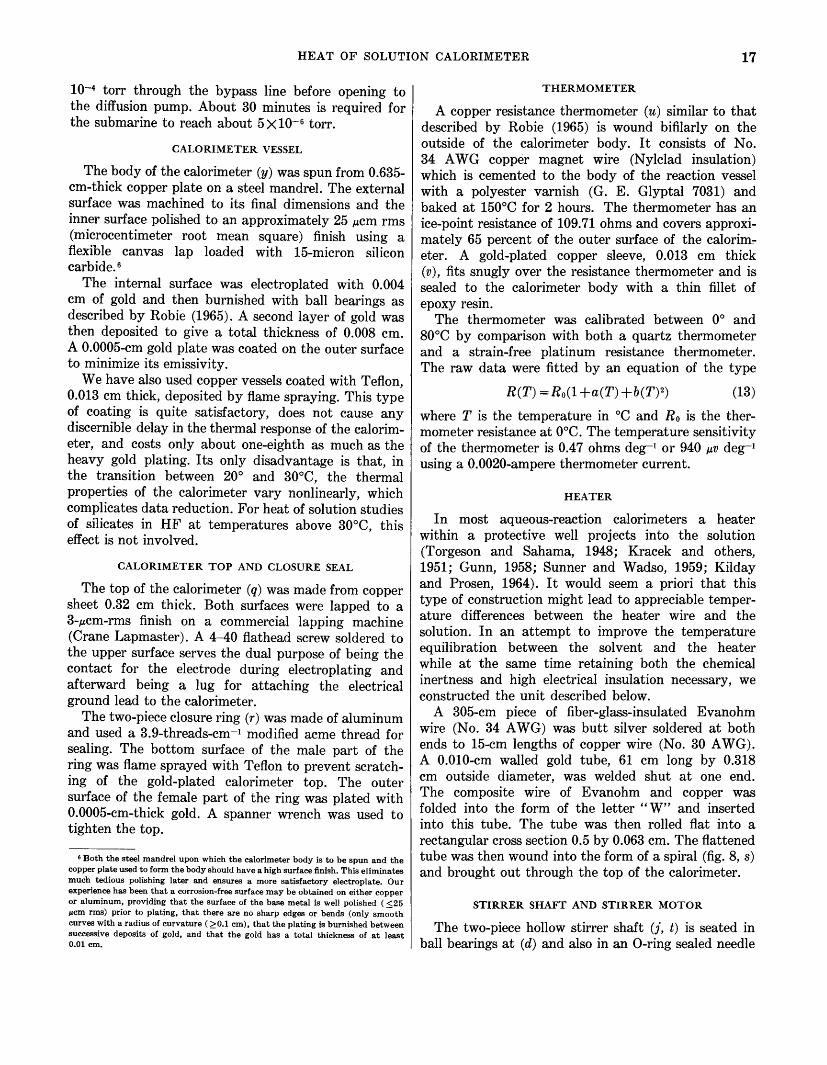
The body of the calorimeter (y) was spun from 0.635-cm-thick copper plate on a steel mandrel. The external surface was machined to its final dimensions and the inner surface polished to an approximately 25 ~em rms (microcentimeter root mean square) finish using a flexible canvas lap loaded with 15-micron silicon carbide. 6
The internal surface was electroplated with 0.004 em of gold and then burnished with ball bearings as described by Robie (1965). A second layer of gold was then deposited to give a total thickness of 0.008 em. A 0.0005-cm gold plate was coated on the outer surface to minimize its emissivity.
We have also used copper vessels coated with Teflon, 0.013 em thick, deposited by flame spraying. This type of coating is quite satisfactory, does not cause any discernible delay in the thermal response of the calorimeter, and costs only about one-eighth as much as the heavy gold plating. Its only disadvantage is that, in the transition between 20° and 30°C, the thermal properties of the calorimeter vary nonlinearly, which complicates data reduction. For heat of solution studies of silicates in HF at temperatures above 30°C, this effect is not involved.
CALORIMETER TOP AND CLOSURE SEAL
The top of the calorimeter (q) was made from copper sheet 0.32 em thick. Both surfaces were lapped to a 3-~cm-rms finish on a commercial lapping machine (Crane Lapmaster). A 4-40 flathead screw soldered to the upper surface serves the dual purpose of being the contact for the electrode during electroplating and afterward being a lug for attaching the electrical ground lead to the calorimeter.
The two-piece closure ring (r) was made of aluminum and used a 3.9-threads-cm-1 modified acme thread for sealing. The bottom surface of the male part of the ring was flame sprayed with Teflon to prevent scratching of the gold-plated calorimeter top. The outer surface of the female part of the ring was plated with 0.0005-cm-thick gold. A spanner wrench was used to tighten the top.
& Both the steel mandrel upon which the calorimeter body is to be spun and the copper plate used to form the body should have a high surface finish. This eliminates much tedious polishing later and ensures a more satisfactory electroplate. Our experience has been that a corrosion-free surface may be obtained on either copper or aluminum, providing that the surface of the base metal is well polished ( ~25 "em rms) prior to plating, that there are no sharp edges or bends (only smooth curves with a radius of curvature ( ~0.1 em), that the plating is burnished between successive deposits of gold, and that the gold has a total thickness of at least 0.01 em.
THERMOMETER
A copper resistance thermometer ( u) similar to that described by Robie (1965) is wound bifilarly on the outside of the calorimeter body. It consists of No. 34 AWG copper magnet wire (Nylclad insulation) which is cemented to the body of the reaction vessel with a polyester varnish (G. E. Glyptal 7031) and baked at 150°C for 2 hours. The thermometer has an ice-point resistance of 109.71 ohms and covers approximately 65 percent of the outer surface of the calorim~ eter. A gold-plated copper sleeve, 0.013 em thick ( v), fits snugly over the resistance thermometer and is sealed to the calorimeter body with a thin fillet of epoxy resin.
The thermometer was calibrated between 0° and 80°C by comparison with both a quartz thermometer and a strain-free platinum resistance thermometer. The raw data were fitted by an equation of the type
R(T) = Ro(1 +a(T) +b(T) 2) (13)
where T is the temperature in oc and Ro is the thermometer resistance at 0°C. The temperature sensitivity of the thermometer is 0.47 ohms deg-1 or 940 ~v deg-1
using a 0.0020-ampere thermometer current.
HEATER
In most aqueous-reaction calorimeters a heater within a protective well projects into the solution (Torgeson and Sahama, 1948; Kracek and others, 1951; Gunn, 1958; Sunner and Wadso, 1959; Kilday and Prosen, 1964). It would seem a priori that this type of construction might lead to appreciable temperature differences between the heater wire and the solution. In an attempt to improve the temperature equilibration between the solvent and the heater while at the same time retaining both the chemical inertness and high electrical insulation necessary, we constructed the unit described below.
A 305-cm piece of fiber-glass-insulated Evan ohm wire (No. 34 A WG) was butt silver soldered at both ends to 15-cm lengths of copper wire (No. 30 AWG). A 0.010-cm walled gold tube, 61 em long by 0.318 em outside diameter, was welded shut at one end. The composite wire of Evanohm and copper was folded into the form of the letter "W" and inserted into this tube. The tube was then rolled flat into a rectangular cross section 0.5 by 0.063 em. The flattened tube was then wound into the form of a spiral (fig. 8, s) and brought out through the top of the calorimeter.
STIRRER SHAFT AND STIRRER MOTOR
The two-piece hollow stirrer shaft (j, t) is seated in ball bearings at (d) and also in an 0-ring sealed needle
18 CALORIMETERS, HEAT OF SOLUTION AND LOW-TEMPERATURE HEAT CAPACITY MEASUREMENTS
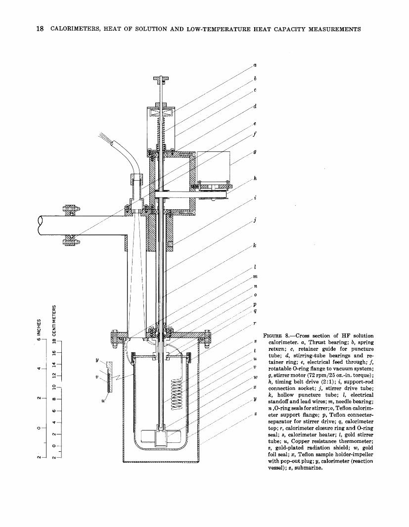
a
FIGURE 8.-Cross section of HF solution calorimeter. a, Thrust bearing; b, spring return; c, retainer guide for puncture tube; d, stirring-tube bearings and retainer ring; e, electrical feed through; J, rotatable 0-ring flange to vacuum system; g, stirrer motor (72 rpm/25 oz.-in. torque); h, timing belt drive (2: 1); i, support-rod connection socket; j, stirrer drive tube; k, hollow puncture tube; l, electrical standoff and lead wires; m, needle bearing; n ,0-ring seals for stirrer; o, Teflon calorimeter support flange; p, Teflon connecterseparator for stirrer drive; q, calorimeter top; r, calorimeter closure ring and 0-ring seal; s, calorimeter heater; t, gold stirrer tube; u, Copper resistance thermometer; v, gold-plated radiation shield; w, gold foil seal; x, Teflon sample holder-impeller with pop-out plug; y, calorimeter (reaction vessel); z, submarine.

HEAT OF SOLUTION CALORIMETER 19
bearing (m) just above the point of entrance to the calorimeter. The upper part of the stirrer shaft is a stainless steel tube. The lower part of the stirrer shaft (t), in direct contact with the solvent, is constructed of gold. It is connected to the upper part by a Teflon connecter (p) to avoid direct metal-to-metal contact and to reduce heat transfer. The connecter contains an 0-ring which forms a pressure-tight seal against the puncture tube (k). The outside diameter of the stirrer rod is sealed at the top of the calorimeter by two surface-flourinated (Lubrin) 0-rings to form a gas-tight rotatable seal capable of holding 3.5 atmospheres internal pressure. These 0-rings are removed when the calorimeter is operated at constant pressure.
A capacitor reversible synchronous motor (g, Superior SS 25, 72 rpm/1.8 em-kg torque) is rigidly mounted on a bracket integral with the main vertical tube of the submarine. It drives the stirrer at 144 rpm through a toothed timing belt drive (h) and thus eliminates possible variation in the stirring rate due to belt slippage.
PUNCTURE TUBE
The puncture device (k) is a round-bottomed alumina tube having a 0.08-cm wall.7 The sample is brought into contact with the solvent by a sharp downward thrust on the shaft of the plunger. This ruptures the gold seal and pushes . out the Teflon plug, thus permitting the sample to react with the solvent. A springloaded thrust bearing (a) in a retaining cage (c) is attached to the puncture tube. The retaining cage prevents the puncture tube from being expelled from the calorimeter when a gas-producing reaction, such as the solution of a carbonate in HCl, takes place.
The hollow construction permits the solution to be cooled in place without disassembling the calorimeter. A small amount of LN 2 is squirted into the puncture tube for cooling. This allows one to make the solution measurements over the same temperature interval as the electrical calibration, if desired (Gunn, 1958). (See fig. 10.)
SAMPLE HOLDER AND IMPELLER ASSEMBLY
The sample holder-impeller assembly (x) was machined from Teflon rod. The combined internal sample holder-impeller was designed to eliminate most of the inconvenience inherent in the methods of sample introduction used with the type of HF calorimeter described by Torgeson and Sahama (1948). Teflon was used because of its chemical inertness, ease of fabrica-
7 We have experimented with gold-plated and Teflon-coated hollow tubes with limited success. Eventually the abrasive nature of the samples scratched through the inert coating and permitted the acid to attack the base metal (stainless steel).
tion, and low cost. Mter filling 8 and weighing, the sample holder is screwed onto the lower end of the gold end of the stirrer tube. A breakable gold foil seal ( w) 0.003-cm thick at the top and a pop-out Teflon plug at the bottom of the sample holder separate the sample from the solvent prior to the initiation of the solution reaction.
CALORIMETER SUPPORT CONNECTER
The calorimeter is supported from the top plate of the submarine by a double-flanged Teflon tube (o). The support tube seals against the top plate of the submarine and against the calorimeter top (q) with rubber 0-rings. A double 0-ring seal (n) on the inner surface of the support tube seals the stirrer tube.
OPERATION AND DATA REDUCTION
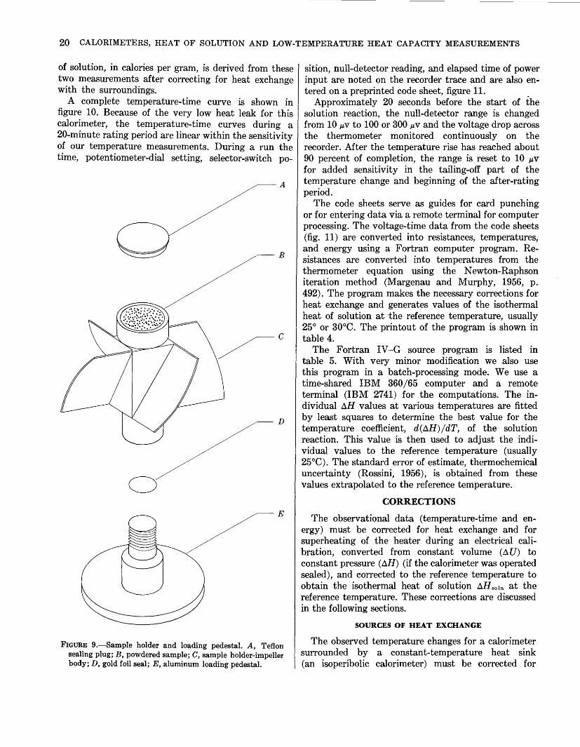
The Teflon sample holder (C), figure 9, with the gold foil gasket (D) in place, is screwed onto an aluminum pedestal (E) for convenience in loading. The sample, -50-mesh powder, is poured into the holder, compressed lightly with a Teflon or polished stainless steel rod, and weighed. The bottom plug (A) is pressed into place to seal the holder and the entire assembly is inverted. The aluminum pedestal is removed and the filled sample holder is screwed onto the base of the stirring tube. A more complete description of this type of sample holder is given in Waldbaum and Robie (1970). The calorimeter, filled with a weighed amount of solvent, is then connected to the calorimeter top using the closure ring, the thermometer leads are soldered to their terminals, and the base of the submarine is attached. The complete assembly is mounted in the constant-temperature bath and locked into position using the support rods. The assembly is then connected to the vacuum system, the vacuum pumps are started, and the stirrer motor is turned on. Assembling the system requires approximately 15 minutes, and it takes about 30 minutes for the vacuum to reach 5 X 10⁻⁶
torr. The calorimeter is then heated rapidly to the starting temperature of the initial calibration period and allowed to come to thermal equilibrium for 10 minutes before measurements are begun.
A heat of solution experiment consists of measuring the amount of electrical energy required to raise the temperature of the calorimeter a certain number of degrees (calibration) and observing the temperature change caused by the solution of a specified amount of sample in the calorimeter solvent (reaction). The heat
s We have found a Parr pellet press very useful for increasing the amount of sample that can be contained in the sample holder. The original press dies were replaced with ones made of hardened type 416 stainless steel with an inside diameter about 0.01 em less than the inside diameter of the sample holder. After compaction the sample can be pressed directly from the die into the sample holder.
20 CALORIMETERS, HEAT OF SOLUTION AND LOW-TEMPERATURE HEAT CAPACITY MEASUREMENTS
of solution, in calories per gram, is derived from these two measurements after correcting for heat exchange with the surroundings.
A complete temperature-time curve is shown in figure 10. Because of the very low heat leak for this calorimeter, the temperature-time curves during a 20-minute rating period are linear within the sensitivity of our temperature measurements. During a run the time, potentiometer-dial setting, selector-switch po-
A
--B
~c
D
0 E
FIGURE 9.-Sample holder and loading pedestal. A, Teflon sealing plug; B, powdered sample; C, sample holder-impeller body; D, gold foil seal; E, aluminum loading pedestal.
sition, null-detector reading, and elapsed time of power input are noted on the recorder trace and are also entered on a preprinted code sheet, figure 11.
Approximately 20 seconds before the start of the solution reaction, the null-detector range is changed from 10 J.LV to 100 or 300 J.LV and the voltage drop across the thermometer monitored continuously on the recorder. Mter the temperature rise has reached about 90 percent of completion, the range is reset to 10 J.LV
for added sensitivity in the tailing-off part of the temperature change and beginning of the after-rating period.
The code sheets serve as guides for card punching or for entering data via a remote terminal for computer processing. The voltage-time data from the code sheets (fig. 11) are converted into resistances, temperatures, and energy using a Fortran computer program. Resistances are converted into temperatures from the thermometer equation using the Newton-Raphson iteration method (Margenau and Murphy, 1956, p. 492). The program makes the necessary corrections for heat exchange and generates values of the isothermal heat of solution at the reference temperature, usually 25° or 30°C. The printout of the program is shown in table 4.
The Fortran IV -G source program is listed in table 5. With very minor modification we also use this program in a batch-processing mode. We use a time-shared IBM 360/65 computer and a remote terminal (IBM 27 41) for the computations. The individual t::.H values at various temperatures are fitted by least squares to determine the best value for the temperature coefficient, d(t::.H)/dT, of the solution reaction. This value is then used to adjust the individual values to the reference temperature (usually 25°C). The standard error of estimate, thermochemical uncertainty (Rossini, 1956), is obtained from these values extrapolated to the reference temperature.
CORRECTIONS
The observational data (temperature-time and energy) must be corrected for heat exchange and for superheating of the heater during an electrical calibration, converted from constant volume (t::.U) to constant pressure (t::.H) (if the calorimeter was operated sealed), and corrected to the reference temperature to obtain the isothermal heat of solution AH sotn at the reference temperature. These corrections are discussed in the following sections.
SOURCES OF HEAT EXCHANGE
The observed temperature changes for a calorimeter surrounded by a constant-temperature heat sink (an isoperibolic calorimeter) must be corrected for

CORRECTIONS 21
heat exchange between the calorimeter and the constant-temperature bath. The total rate of heat transfer between the calorimeter and the surrounding bath can be expressed as
surrounding submarine and upon the emissivities of the outer surface of the calorimeter and inner surface of the submarine, and it is proportional to the difference in the fourth powers of the absolute temperatures of the calorimeter and submarine.
dQjdt=BN(Tc-TB) cal min-1 (14)
where B N is the thermal conductance, in calories degrees-1 minutes-1; Q is heat, in calories; t is time; and T c and T B are the absolute temperatures of the calorimeter and bath. Heat exchange between the calorimeter and the bath takes place by four separate mechanisms: radiation, conduction through solid connections, and convection and conduction through a gas.
dQ I dt = o-A cF ( T c 4 - T 8 4). (15)
In the above relation T s is the temperature of the submarine and is identical with T B, the bath temperature, o- is the Steffan-Boltzman constant, Ac is the surface area of the calorimeter, and F is the shape factor. The shape factor (Scott, 1959) is
F =e. ·e,;(e.+ ~:(1-e,) e.) (16) RADIATION
Heat exchange due to radiation depends upon the ratio of the surface areas of the calorimeter and the
where A 8 is the area of the inner wall of the submarine and es and ec are the surface emissivities of the sub-
32.0 RUN H-10 HYDROMAGNESITE IN 4 N HCI
- 0.000518 deg min-I 124.8
124.6
31 ·5 1----11NITIAL CALIBRATION--_______,.~R1 EACTION PERIOO--,-J
u 31.0 0
z
w .. a:: ~30.5 <( a:: w a.. :!!: w 1-
30.0
-0.000098 deg min-I
en :!!:
124.4 ~ z
I LL.i ! u
I I 124.2 ~ ___ !__C!?Ll!!_~!lS!L____ ______ _ ______________________ _
FINAL CA~IBR~TION--~ ~
! ! u; I I W ! ! a:: ! ! 124.0 a:: I I w I I I-I I W I I ~ I I 0 I I ~
! ! I i i 123.8 a:: ~------------------------~-----------------------------:-------------------------:-----:-----------~------- w ! ! I I I ~ I I ! ! ! I I I I I
I I ! l ! I l I I I I I I I I
l ! l l i
i ! i ! ! r--HEATER ON i ! HEATER ON --4 r--! ! ! i i
T bath --------------~---------
_ 0.000745 de min-I 123.6
123.4 I l \ l l 29'~1L0-0----~112L0--~--Iul4_0 ______ 1~16-0~----~~18_0 ______ !?~.0-0~----~2~2-0----~~2~4-0~----~2~6-0~
TIME
FIGURE 10.-Temperature-time curve for the heat of solution of 4.6 g of hydromagnesite in 4 N HCl (run H-10). The shaded areas are
it, (Too-T)dt deg min.
t;
For the initial calibration period this integral is positive, and for the final calibration period it is negative. The temperaturetime changes are indicated for the rating periods.

22 CALORIMETERS, HEAT OF SOLUTION AND LOW-TEMPERATURE HEAT CAPACITY MEASUREMENTS
TABLE 4.-Printout of computer reduction
HEAT EXCHANGE CALCULATIONS FOR SOLUTION CALORIMETRY, DATE IS 1 0/111/1971
RUN H 1 0 DATE-21 NOV., 1966 BOOK II PAGE 86•87 SAMPLE TE COALINGA, CAL. VACUUM(INITIAL-3.5E-5 FINAL-3.2E-5) BATH TEMPERATURE 28 .• 85
TIME THERMOMETER EMF THERMOMETER CURRENT RESIST]\NCE TEMPERATURE DRIFT HR MIN MINUTES DIALS NULL ZERO SUM DIALS NULL ZERO SUM OHMS (C) DEG/MIN
18.30.0 1110.000 132640. -1.35 0.05 132638.60 107335. 2.53 0.05 107337.48 123.571561 29.4511944 18.48.0 1128.000 132640. 5.32 0.05 132645.27 107335. 2.39 o.os 107337.34 123.577934 29.468441 0.0007498
HEATING PERIOD 1 18.50.0 1130.000 29.469941 TI
357712. 2.05 o.o 357714.05 18441111. 0.112 o.o 18114114.42 29.472941 TI 1
35.769079 VOLTS 0.18325211 AMPS 195.1905114 30.312501 TF' 18.58.0 1138.000 30.313656 TF
TIME 480.060 SEC ENERGY 752.0740 CAL HEAT CAPACITY 895.105844 CAL/DEG MEAN TEMP. 29.892721
19. o.o 1140.000 133075. -4.32 o.o 133070.68 107332. 2.68 o.o 107334.68 123.971338 30.314233 19.27.0 1167.000 133075. -0.53 0.05 133074.42 107332. 2.56 0.05 107334.51 123.981019 30.322028 0.0002887
SOLUTION PERIOD 19.28.0 1168.000 30.322317 TI
30.322333 TI 1
19.30.0 1170.000 133491. 0.63 o.o 133491.62 107332.07 124.372542 31.150987 DICKINSON TEMP 30.740732 OCCURS 0.06 MIN AFTER INITIAL TIME 31.159131 TF'
20. 5.0 1205.000 ElAPSED TIME 37.00 31.155604 TF
20. 6.0 1206.000 133492. 1. 77 o.o 133493.77 107330. 1.96 o.o 107331.96 124.374677 31.155509 20.36.0 1236.000 133492. 0.14 0.01 133492.13 107330. 1.81 0.01 107331.80 124.373324 31.)52644 -0.0000955
HEATING PERIOD 2 20.37.0 1237.000 31.152549 TI
357110. 0.12 o.o 357710.12 184436. 0.60 o.o 184436.60 31.152167 TI 1
35.768687 VOLTS 0.18324431 AMPS 195.196715 31.989766 TF 1
20.45.0 1245.000 31.987694 TF
TIME 480.070 SEC ENERGY 752.0494 CAL HEAT CAPACITY 897.172306 CAL/DEG MEAN TEMP. 31.570966
20.47.0 1247.000 133904. 8.04 o.o 1339,2.04 107328. 1.44 o.o 107329.44 124.767301 31.986658 21. s.o 1265.000 133904. 3.14 o.o 133907.14 107328. 1.30 o.o 107329.30 124.762897 31.977338 -0.0005178
SUMMARY
CALIBRATION 1 CALIBRATION 2 SOLUTION
DELTA T OBS. TEMPERATURE CORRECTION CORRECTED DELTA T CONVERGENCE TEMP ALPHA (*10000) BN HEAT OF STIRRING POWER OBS HEAT CAPACITY C EXTRAP. TO T(M,SOLN) DELTA II PER GRAM
0.843715 -0.004155
0.839560 30.838117
5.492662 0.491651 0.000543 6.554759
895.105844 895.7090
-164.162.7 DELTA U PER HOL -76843.5173
0.835145 0.002453 0.837599
30.962815 5.042173 0.452370 0.000561 6.554408
897.172306 896.6390
-163.9924 -76942.7314
0.833287 0.003511 0.836798
30.962815 5.042173 0.452370 0.000561
marine and calorimeter respectively. If we call the fraction of the thermal conductance caused by radiation BR, then
(17)
CONDUCTION THROUGH SOLID CONNECTIONS
The heat leak due to conduction through each of the solid connections is proportional to T c- T B, the thermal conductivity, ki, and the cross-sectional area, ai, and is inversely proportional to the length of the heat path, l i· The total is
dQjdt=~kt{},\Tc-TB) (18) i=l li
DEG C DEG C DEG C DEG C 1/MIN CAL/DEG/MIN DEG/MIN WATTS CAL/DEG CAL/DEG CAL CAL
SAMPLE WEIGHT SAMPLE MASS FORMULA WEIGHT
4.5688 GRAMS 4.5705 GRAMS
467.6740 GRAMS
INTEGRAL (E/DT) 4939190.0100 M-VOLT-MIN (T(INF)-TM) -6.9624 DEG-MIN
D(DELTA Q)/DT 0.2035 CAL/DEG-GM D(DELTA H)/DT 95.1631 CAL/DEG-MOL
DELTA QAT 30.000 -164.4161 CAL/GRAM DELTA HAT 30.000 -76893.1244 CAL/MOL
where the summation indicates the contributions due to the two Teflon connecters, the eight copper lead wires, and the puncture tube. The thermal conductance due to solid conduction is thus
k1a1 k2a2 Bk=T+---z;-+···· (19)
CONDUCTION AND CONVECTION THROUGH A GAS
Heat transfer by convection and conduction through a gas varies with pressure. The theory is complicated, but the significant point is that at pressures below 5 X 10⁻⁶ torr the mean free path of the gas molecules is large compared with the separation of the calorimeter
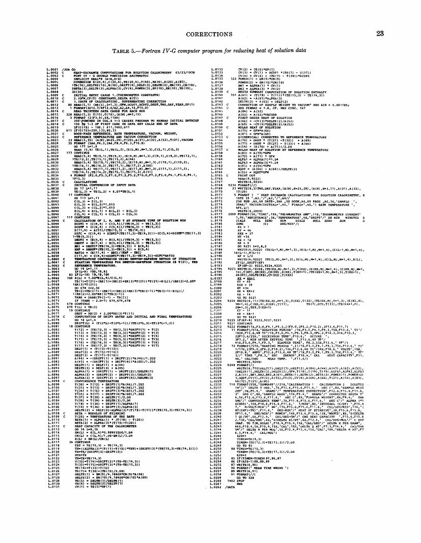
CORRECTIONS
TABLE 5.-Fortran IV-G computer program for reducing heat of solution data
L.0001 /JOB GO L.0002 C HEA'l'-EXCIIAIIGE COMPUTATIONS FOR SOWTION CALORIMETRY 03/23/1970 L. 0003 C I!"'RT IV - G OOUBLE PRECISION ARI'l'IIMETIC L. 0004 IMPLICIT REAL'S (A-H,D-Z) L.0005 DIMENSION E(20,4) ,C(20,4) ,TE(20,4) ,T(40) ,RK(6) ,R(20) ,A(85), L. 0006 1"1'8( 50) ,DELTKS(10) ,8(50) ,DRIFT(4) ,DELT(J) ,DELTEU) ,EM(10) ,CM(10), L.0007 2BETA(3) ,DELTK(J) ,ALPHA(J) ,CV(4) ,POWER(J) ,SP( 10) ,ES( 10) ,TS ( 10), L.0008 3G(30) L. 0009 C INITIAL ENTRY CARDS 1. (THERIIOIIETER CONSTANTS) L.0010 C 2. (GP'W,CP(T) CONSTANTS,DELTA H(T)) !;;"0011 C 3. (DATE OF CALCULATION), SUPERHBATING CORRECTION L.0012 80 READ(5,1) (RK(I) ,I•1, 3) ,GPW,DCDT1,DCDT2,DHDT,'l'MO,DAY ,YEAR,SP(1) L.0013 1 I!"'IUIAT(JD12. 7/U12.0/A2,A2,A4,1X,F10.0) L.OOU C READ THIRTEEN DATA CARDS I!"'R EACH RUN L.0015 328 READ(S,J) G(15),G(16),(A(N),N-2,12) L.0016 3 I!"'RIIAT ·(2(FJ.0),6X,11A6)
~:~~~~ ~~g·-~~~D~NF~~TS~ ~U~~/~~~ :0~ ~:~!IAL ENTRIES
L.0019 IF(G(15) - 100.) 611,1402,611 L.0020 611 IF(G(15h·250.)3J,80,33 L. 0021 BOOK-PAGE REl'BRENCE, BATH 'l"EliPERATURE, VACUUM, IIEIGHT, L. 00 2 2 REFERENCE 'l'EIIPERATURE AND VACUUM CORRECTION L.0023 33 READ(5,35) (A(N) ,N•25,29) ,T(20) ,A(J1) ,A(32) ,A (52) ,T(21) ,VACORR L.0024 35 FORMAT (SA6,F6.3,2A6,F8.4,F6.J,F10.8) L.0025 DO 177 L-1,8 L.0026 READ (5,4) TE(L,1),TE(L,2),(E(L,M),M•1,J),C(L,1),C(L,2) L.0027 177 CONTINUE L. 0028 READ (5, 4) TE ( 9,1) ,TE (9, 2), (E (9,H) ,H-1, 3) ,C (9,1) ,C (9,2) ,TE (12,1), L. 0029 ITE( 12 ,2) ,TE ( 13,1) ,TE ( 13 ,2) ,A(Q6) L. 0030 READ (5, 4) TE (1 0,1) ,TE( 1 0,2), (E (1 O,M) ,H-1, 3) ,C (10,1) ,C (1 0, 2), L.OOJI ITE( 16,1) ,TE( 16,2) ,TE( 17,1) ,TE( 17 ,2) ,A(60) L.OOJ2 READ(S,4) TE(11,1) ,TE(11,2), (E(11,M) ,H-1,3) ,C(11,1) ,C(11,2), L. 0033 ITE( U,1) ,TE( 14, 2) ,TE(15,1) ,TE (1 S, 2) ,A (51) L. 003~ ~ I!"'RIIAT (F2.0,FS. 3,F7. O,P'7. 2 ,P'S. 2 ,FI 0.0 ,F7. 2,F3. O,F4. 1,F3.0,F~. 1, L.0035 1F15. 3) L. 0036 CALCULATIONS L.0037 INITIAL CONVERSION OF INPUT DATA L.0038 DO 17 L-1,11 L.0039 TE(L,J) • TE(L,2) + 6.D1'TE(L,1) L. 0040 17 CONTINUE L.0041 DO 117 L-1,11 L.0042 C(L,J) • E(L,J) L.0043 E(L,2) • E(L,2)•1.01J L.OOU C(L,2) • C(L,2)•1.01J L.0045 E(L,4) • E(L,1) + E(L,2) - E(L,3) L.0046 C(L,4) • C(L,I) + CIL,2) - C(L,J) L. 0047 117 CONTINUE L.OOU C CALCULATION or I, R, AND TAT AVERAGE TIME or SOLUTION RUN L.0049 DIDTI • (C(4,4) - CI3,4))/(TE(4,3) - TE(J,3)) L.OOSO DIDTF • (C(6,4) - CI5,4))/(TE(6,3) - TE(S,3)) L.0051 E(11,4) • A(S1)/(TE(15,3) - TE(U,3)) L.0052 DIFC • (C(4,4) + DIDTI*(TE(11,J)-TE(4,3)))-(C(5,4)+DIDTF*(TE(11,3) L.OOSJ 1-TE(5,3))) L.0054 DJIDfi • (B(4,4) - E(3,4))/(TE(4,3) • TB(J,l)) L.OOSS DBDTF • (E(7,4) - E(S,4))/(TB(6,3) • TB(S,J)) L.0056 BBI • DEDTI• (TE(U,J)•TB(4,J)) + B(4,4) L.0057 BBF • DBDTFO(TB(15,3)•TE(5,l)) + 1(5,4) L.OOS8 RATIO • (B(11,4) • BBI)/(BBF- BBI) L.OOS9 C(11,4) • C(4,4)+DIDTI•(TE(11,3)·TB(4,l))•DIFC*RATIO L. 0060 TEMPERATURE CONVERSION USING IIBifTON•IIAPBSOII MB'l'ROD OP ITERATION L.0061 STARTING TEMPERATURE I!"'R NBI!'l'OII-IIAPHJ'SON ITERATION IS T(21), THE L. 0062 REl'BRBIICE TEMPERATURE. L.0063 DO 19 L-1,11 L.0064 IP(L-9) 100,19,83 L.0065 83 IP(L-10) 1t,19,100 L.0066 100 R(L) • I.D.:IOB(L,4)/C(L,4) L. 0067 TB( 1) •T (21)- (RK( I)+ (RK(2)+RJC( 3) *T(21)) OT(21) -R(L)) / (RK(2) +2.DO• L.0068 IRK(J)OT(21)) L.0069 DO 678 I•2,50 L. 0070 TB(I) •TS(I-1)- (RIC( 1) + (Rlt(2)+RJC( 3) •TB( I-1)) •TB (I-1) -R (L)) / L.0071 1 (RK(2)+2.DO'RK(J) *TB(I-1)) L.0072 TABS • DABS(TB(I-1) - TB(I)) L.0073 IF (TABS - 2.D-7) 679,679,678 L. 007~ 678 CONTINUE L.0075 679 T(L) • TB(I) L.0076 19 CONTINUE L.0077 DRDT • RK(2) + 2.DO•RK(J)*T(11) L.0078 C COMPUTATION OF DRIFT RATES AND INITIAL AND PINAL TEMPERATURES L.0079 DO 18 L-1,4 L.OOSO DRIFT(L) • (T(2'L)-T(2•L-I))/(TE(20L,3)-TE(20L-1,J)) L.0081 18 CONTINUE L.0082 T(l2) • (TE(I2,3) - TE(2,3))*DRIFT(1) L.0083 T(13) • (TE(13,3) - TE(J,J))*DRIFT(2) L.0084 T(14) • (TE(14,3) - TE(4,J))•DRIFT(2) L.0085 T(15) • (TE(15,3) - TE(5,J))*DRIFT(3) L.U086 T(16) • (TE(I6,3) - TE(6,3))•DRIFT(3) L. 0087 T ( 11) • (TE( 17, 3) - TE (7, 3)) •DRIFT (4) L.0088 DELT(I) • (T(IJ)-T(12)) L.0089 DELT(2) • (T(I5)-T(14)) L.0090 DELT(J) • (T(I7)-T(16))
+ T(2) + T(J) + T(4) + T(5) + T(6) + T(7)
L.0091 A(44) • -(DRIFT(!) + DRIFT(2))*A(46)/1.2D2 L.0092 A(45) • -(DRIFT(J) + DRIFT(4))'A(60)/1.2D2 L.0093 DELTK(I) • DELT(1) + A(44) L.0094 DELTK(J) • DELT(J) + A(45) L.0095 ALPHA(!) • (DRIFT(1) - DRIFT(2))/DELTK(1) L.0096 ALPHA(2) • (DRIFT(2) - DRIFT(3))/DELT(2) L.0097 ALPIIA(3) • (DRIFT(3) - DRIFT(4JJ/DELTK(l) L.0098 C CONVERGENCE TEMPERATURE L.0099 T(30) • T(12) + DRIFT(1)'A(46)/1.2D2 L.OIOO T(JI) • T(13) - DRIPT(2)'A(46)/1.2D2 L.0101 T(34) • T(16) + DRIFT(J)OA(60)/1.2D2 L.0102 Tl35) • T(11) - DRIFT(4)0A(60)/1.2D2 L.0103 T(J7) • T(JO) + DELTK(I)/2.00 L.0104 T(39) • T(J4) + DELTK(J)/2.00 L.OIOS T(18) • T(30) + DRIFT(I)/ALPHA(I) L.0106 T(19) • T(34) + DRIFT(3)/ALPHA(J) L. 01 Q7 DELTK (2) • DELT (2)-ALPHA(3) 0 (T (19) -T( 11)) • (TE( 15, 3)-TE( 14, 3)) L.0108 C BETA -MODULUS OF STIRRING L.0109 C T(20) • TEMPERATURE or THE BATH L.0110 BETA(!) • ALPHA(!) O .(T(18) - T(20)) L.0111 BETA(2) • ALPHA(J) • (T(19)-T(20)) L.0112 C HEAT CAPACITY OF THE CALORIMETER L.0113 DO 34 L-9,10 L.0114 EM(L) • E(L,4)•0.999935D0/1.D4 L.0115 CM(L) • C(L,4)/1.D6-EM(L)/3.D4 L.0116 R(L) • EM(L)/CM(L) L. 0117 34 CONTINUE L.0118 TXT • TE(15,3) - TE(14,3) L.0119 TX• ( (ALPHA(l) o (T( 11 )-T(19)) 'TXT)+ (DRIFT(J) 0(TE(15,3)•TE(14, 3)))) L.0120 TX•TX/(DRIFT(J)-DRIFT(2)) L.0121 DTX•TX L. 0122 TX-TX+TE ( 14, 3) L. 0123 T ( 32) •T( 14)+DRIFT(2) o (TX-TE ( 1Q, 3)) L. 0124 T (33)-T( 15)+DRIFT (3) • (TX-TE( 15,3) l L.0125 TS(10)-T(33)-T(32) L.0126 "1'5(7)• T(32)+(TS(10)/2.DO) L.0127 DELTE(I) • EM(9)/4.1UD00CM(9)'A(Q6) L.0128 DELTE(2) • EM(10)/4.18QDO•CM(IO)•A(60)
t:m~ ~!~l : g:~i:m~g~~~m L.0131 CV(I) • TS(S)•SP(I)
L.0132 CV(2) • TS(6)•SP(1) L.OIJJ CV (3) • CV (1) + DCDTI • (TS (7) - T(37)) L.0134 CV(4) • CV(2) + (TS(7) - T()9))'DCDT2 L.0135 322 POWER( 1) • EM(9) •CH(9) L.0136 POWER(2) • EM(10)'CH(10) L.0137 BNI • ALPHA(!) • CV(I) L.0138 BN2 • ALPHA(l) O CV(2) L.0139 C BEGIN SUMMARY COMPUTATION OF SOWTION ENTHALPY L.OUO 701 A(61) • (T(19) - T(11))0(TE(15,3) - TE(14,3)) L.OUI A(62) • -A(61)'A..PIIA(l) L.0142 DELTK(2) • A(62) + DELT(2) L.~143 CORRECTION OF SMIPLE WEIGHT TO VACUUM" RHO AIR • 0.001185: L.014~ RIIO PERHAS • 7.8, CF. NBS CIRC. 547 L.014'i A(84) • A(52) L.0146 A(52) • A(52)•VACORR L.0147 C FIRST ORDER HEAT OF SOLUTION L.OU8 A(66) • -L'V(3) 'DELTK(2)/A(52) L.OU9 A(69) • -CV(4)•DELTK(2)/A(52) L.0150 C MOLAR HEAT OF SOLUTION L.0151 A(75) • GFW'A(66) L.0152 A(81) • GP'W 0 A(69) L.0153 C Q(CHEMICAL) CORRECTED TO REFERENCE TEMPERATURE L.0154 A(70) • DHDT • (T(21) -T(32)) + A(69) L.0155 A(71) • DHDT O (T(21) - T(Jl)) + A(66) L.0156 A(54) • (A(70) + A(71))/2.DO L.0157 C MOLAR HEAT OF SOLUTION AT REFERENCE TEMPERATURE L.0158 A(83) • A(70)'GP'W L. 0159 A(72) • A(71) o GP'W L. 0160 ALP AI • ALPIIA(I) •I.DQ L.0161 ALPAJ • ALPHA()) •1.D4 L.0162 A(85) • A(54)0GP'W L.0163 DQDT • (A(66) - A(69))/DELTK(2) L.0164 A(55) • DQDT'GP'W L.0165 C PRINT OUT L.0166 READ(9,9222) L. 0167 WRITE(6, 9234) L. 0168 9234 P'ORMAT(/ /) L. 0169 23 WRITE(6, 5) 'l'HO,DAY, YEAR, (A(N) ,N•25, 29), (A(N) ,N•l, 11) ,A (31) ,A (32), L.0170 1T(20) L. 0171 5 FORMAT ( ' HEAT EXCHANGE CALCULATIONS I!"'R SOLUTION CALORIMETRY, D L.0172 lATE IS ',A2,'/',A2,'/',A4// L.0173 25H RUN ,A6,6H DATE-,2A6 ,5H IJOOK,A6,6H PAGE ,A6,3X,'SAHPLE ', L.0174 39A6/' VACUUM(INITIAL-',A6,' FINAL-',116,') BATH TEMPERATURE', L.0175 4F6.2/) L.0176 WRITE(6,2009) L.0177 2009 FORHAT(5X,'TIHE',19X,'THERMOMETER EMP',11X,'TIIERMOMETER CURRENT' L. 0178 1, 9X, 'RESISTANCE' , JX, 'TEMPERATURE' , 4X, 'DRIFT'/' HR MIN MINUTES L. 0179 2IALS NULL ZERO SUM DIALS NULL ZERO SUM L.0180 3HHS (C) DEG/HIN'/J L.0181 KZ • 1 L.0182 KY • 46 L.0183 KXX • 37 L. OIBQ NY •30 L.0185 KX • 12 L. 0186 KK • 9 L.0187 DO 9221 L-2,8,2 L. 0188 WRITE (6, 9222) (TE(L-1 ,H) ,H•I, 3), (E (L-I,H) ,H•I, 4), (C (L-I,H) ,M•I, 4), L.0189 IR(L-I),T(L-1) L. 0190 KP • L/2 L. 0191 WRITE (6, 9222) (TE (L,H) ,1~•1, 3), (E (L,H) ,H•l, 4), (C (L,H) ,H-1, 4) ,R (L), L.0192 2T(L) ,DRIFT(KP) L.0193 IF(KP-2) 9223,9224,9225 L. 0194 9223 WRITE (6,1 O)KZ, (TE(KX,H) ,H•l, 3) ,T (KX), (E (KK,H) ,H•I, Q), (C (KK,H) ,H-1, L. 0195 14) ,T (NY) ,F.II (KK) ,CM (KK) ,R (KK), T(NY+I), (TE (KX+I,H) ,H•I, 3) ,T(KX+I), L. 0196 2A(KY) ,DELTE(KZ) ,CV (KZ) ,T(KXX) I..QW _.G..• ntl. L. 0198 KY • 60 L. 0199 KXX = 39 L. 0200 NY •34 L.0201 KK • KK+2 L.0202 KX = 14 L.0203 GO TO 9221 L. 0204 9224 WRITE(6, 11) (TE(KX,H) ,11=1, 3), T(J(X), T ( 32), (TE (KK,H) ,11•1, 3), (E (KK,M), L.0205 1M• I,~) ,C (KK, 4) ,R (KK) ,T ( 11 l, TS ( 7) ,DTX,T()3), (TE (KX+1 ,II), L.0206 2H-1,J),TXT,T(KX+1) r ... o)o·, r.x = 1r. L.0208 KK • KK-1 L.0209 GO TO 9221 L.0210 9225 IF(KP-4) 9223,9221,9221 L. 0211 9221 CONTINUE L. 0212 9222 I!"'RHAT( IX,Fl. 0 ,F4. 1,F9. 3, 2 (F9. 0, 21'6. 2 ,FI 0, 2), 21'13. 6,1'11. 7 l L.0213 11 I!"'RHAT(/51X,'SOLUTION PERIOD' /1X,I'l.O,F4.1,F9.3,75X,P'13.6,' TI'/ L. 0214 192X,F13. 6, 411 TI '/IX,P'l.O ,F4 .1,F9. 3,F9. 0, 2F6. 2 ,Fl 0. 2, 21X,F1 0. 2, L.0215 22F13.6/25X,' DICKII;SON TEMP',F10.6,' OCCURS ', ' L.0216 31!"7.2,' MIN AFTER INITIAL TIM•: ',1'13.6,~H Tl''/ L.0217 41X,F3.0,F4.1,1'9.J,' ELAPSED TIME', P'8.2,53X,F13.o,' TF'/) L.0218 10 FDIUIAT(/51X, 'HEATING PERIOD ',I1/1X,FJ.0,1'4.1,P'9. 3, 75X,F13.6,' TI' L. 0219 1/17X, 2 (F9. 0, 2F6. 2 ,FI 0. 2) ,13X,F13 .6 ,411 TI '/34X,F'10. 6,' VOLTS', 15X, L.0220 2F10.8,' AHPS',F12.6,F13.6,4H TF'/1X,F3.0,F4.1,F9.3,75X,F13.6,' TF' L.0221 3//' TIME ',1'8.3,' SEC ENERGY',F10.4,' CAL ·HEAT CAPACITY',Fil. L.0222 46,' CAL/DEG MEAN TEMP. ',F11.6/) L. 0223 WRITE(6, 9248) L.0224 9248 FORMAT(/) L. 0225 WRITE (6, 71 0) DELT( 1) ,DELT( 3) ,UELT(2) ,A (84) ,A~~~) ,A (~5) ,A (62) ,A (52), L. 0226 1 DEL'rK ( 1) ,DELTK (3) ,DELTK (2i ,GI'W, T( 18 l ,T ( 19), T( 19) ,AI.!' A 1,ALFA3 ,ALFA3 L.0227 2,A (51 l ,BN1,all2,BN2,A (61) ,BETA (1) ,BETA (2) ,BETA 12) ,POWER II) ,POWER 12) L.0228 J,DQDT ,CV (1) ,cv (2 l ,A (55) ,CV (3 l ,CV (4) ,A (69) ,A (66), T 121) ,A (54) ,A (83), L.0229 4A(72) ,T(21) ,A(85) L.0230 710 I'ORHAT(55X,'SUHIIARY'//21X,'CALIBRATION 1 CALIBRATION 2 SOLUTIO L.0231 IN'//' DELTA T OBS.',7X,P'15.6,F15.6,F11.6,' !lEG C',8X,'SAHPLE WEIG L. 0232 2HT', 9X, F9. 4,' GRAMS'/' TEMPERATURE CORRECTION', F12. 6 ,FIS. 6 ,Fil. 6, L.0233 3 1 DF.G C',BX, 1 SAMPU: MASS 1 ,11X,F9.ll,' GRAMS'/' CORRECTED DELTA T' L.0234 4,SX,F12.6,F15.6,F11.6,' DEG C 1 ,8X, 1 FORMULA WEIGHT 1 ,8X,F9.11., 1 GRA L.0235 5MS'/' CONVERGc'NCF. TEMP',7X,F11.6,F15.6,F11.6,' DEG C'/' ALPHA (01 L.0236 60000)',10X,F10.6,F15.6,F11.6,' 1/IUN',8X,'INTEGRAL (E/DT) ',F15.4 L.0237 7,' H-VOLT-HIN'/ 0 BN' ,17X,F15.6,F15.6,F'11.6,' CAL/DEG/HW',11X,' I L.0238 8T(INF)-TH)',F11.4,' DEG-HIN'/' IIEAT OF STIRRWG',3X,F15.6,F1S.6, L.0239 9F11. 6,' DEG/HIN' /' POWER', 1 4X, F15. 6 ,F15. 6, IJX, 'WATTS', 8X, 'D (DELTA L.0240 1 Q) /DT', 6X,F'12. 4,' CAL/DEG-GM' /' OBS HEAT CAPACITY ',F15.6 ,F15 .6 L.0241 2,1JX,'CAL/DEG',6X,'D(DELTA H)/DT',6X,F12.~,' CAL/DEG-MOL'/' C EXT L.02~2 JIIAP. TO T(H,SOLN) ',FlO. 4,F15. 4,1 5X, 'CAL/DEG' /' DELTA H PER GRAM', L.0243 46X,F10.4,5X,F10.4,15X, 0 CAL',10X,'OELTA Q AT 0 ,F7.3,F14.4,' CAL/GHA L.02Q4 SM'/' DELTA H PER MOL 1 ,SX,F12.4,F1S.li,15X, 1 CAL',10X, 1 DELTA H AT',F7 L.0245 6.3,FU.4,' CAL/MOL') L. 0246 KJX•I L. 024 7 TIHEN•TE ( 9, 3) L.0248 TIHEM• (TE( 12, l)+TE( 13, 3)) /2.UO L. 0249 GO TO 85 L.0250 88 TIHEII•TE(10,3) L.0251 TIMEH• (TE( 16, l)+TE( 17, 3)) /2.ll0 L. 0252 KJX•2 L.0253 85 IF(TIMEM-TIIIEN)87,86,87 L.0254 86 IF(KJX-1)88,88,89 L. 0255 87 WRITE ( 6, 90) L.0256 90 I!"'RHAT(' MEAN TIME WRONG ') L.0257 89 WRITE(6,91) L. 0258 91 I!"'IUIAT(/ /) L. 0259 GO TO 328 L.0260 U02 STOP L.0261 END L. 0262 /DATA
23

Vacorr.
/I. 1()10,013171
• L_~~~~~~~~~_L_L_L_L_L_L_L_L_L_L_L_L~
)ftVJ!,,!'W"I•I I t•yr••••l-1 I !I!W,.....tvl I I•'V'V' 1!1'-II"I'V'Vi"'' I .,.,_, I I I I '" 1..-..L__i_--'--'--'--'--'--'---'---'----'----'----'-.-l..---'----'----l..---l..---1.---1.---l..---i
l••v• ,,,.,-, , , •• ,.,..-•--•-•••-• , ¥",.,.,..,_.., , •••vr>,~• ,, ._, .. ,,........,..~-· , ·.-- -· L.-'--'--'--'--'
3 1/~'I!~.Ol • I I ,, :0:113~ 121 l : ::z o &,sj : • _. -~ L__l__1_ -"--'----'---'--L___L_____L__L__j___L....L.....L.._j___L__L._l--L.....J_LJ.......l_...L...L_L_~~
41,~ol..,~-,l I I I I/~~~~ i\7'~ 1- I l;'tl ll;l?l I I 1\~~ -~~ l/oi33.2l_l : :2. 6~ :-~-~-~~-~l__i .L_L_jl_____j----'----'-_l_
-5
• •• ~~~~~L-L-L-L-L-L-L_L_L__L___L__~~i_~i_~~~
6
I I .1 I I I I I I I - -- .I I " •• 1 I i . ~·--~~~~~~~==~ 7
al'/ I !"I~! I I I l/~'~'q'/)'ll1 I I ·~I I //\1 I I •/ll/\1 -~_L lt:o:z:3:2:sl I : I. 2 &'1-~---~--~-'-~' ,_L_l__L___L__L_L_L-L-L-L-L---l..---l.._~~___.J._J_
ti tf
91/oll\di · I · l:~'"'-1-1,·,1 I · " ·/\·,1 I /\·~ -'---' · l/i~44ifM I . o.l/-!IIL slSaJ.: I l(it5:HI.: I~~ 10 I;{Olf/: .. 1 I 1:1:>.-l7,/.a 1 I .o.r1.11 1 .•. olo1-~-- _i/K.4lf3~ [ 0.691
I/D7332II .92ll19lZKl. r lz:olosl.: II : : :4'1:3:c;,r:~:o:.:a:J: I : :S~Iut:ion: : : I ~~~~+-~~~~~~~~-'-~-'--'--'--'--'--'-~~~-'-~~~-L-L-L-L--'--L~--'---'----'-~~--~~----~~~-'--'---'-~---'--L----'-.-l..---'----'--_L---L...__L_---l..---l..---L---l..---l..---L_J_J_J_J~~~~L-L-L-L-~
FIGURE 11.-Coding sheet for heat of solution experiment. The sheet serves as a guide for card punching the time, potentiometer-dial setting, null-detector reading, and elapsed time necessary for reducing a complete heat of solution measurement.
1:'1:) ~
0 > ~ 0 ~ Jo.-4
~ t_:l:j 1-3 t_:l:j ~ .rn ::z:: t_:l:j
> 1-3 0 ":rj
00 0 ~
§ 0 z > z 1:::1
~
~ 1-3 t_:l:j
~ 1-tj t_:l:j ~ > 1-3 ~
~ ::z:: t_:l:j
> 1-3 (")
~ > 9 1-3 ~
~ t_:l:j
> 00 ~
~ ~ t_:l:j
~ 00

CORRECTIONS 25
and submarine wall and heat transfer by these mechanisms is negligible. Ginnings and West (1968) gave an extended treatment of the theory. For our calorimeter, operating in a vacuum of 10-5 torr, the mean free path is about 10 meters, and gaseous conduction and convection are effectively absent. This is in agreement with our experimental observation that the relaxation time 9 between the calorimeter and the constanttemperature bath is essentially independent of pressure below 5 X10⁻⁵ torr.
If we substitute the appropriate numerical values for the emissivities dimensions and temperature in equations 16 and 17, we find that BR~0.32 cal deg-I min-I. Similiarly using the conductivities of Teflon, copper, and stainless steel and the dimensions of the connecter and copper wires, we get from equation 19 that Bk ~0.03 cal deg-I min-I and
BN =BR+Bk~0.35 cal deg-I min-I. (20)
The values of B N observed in an actual calorimetric experiment range from 0.4 to 0.55 cal deg-I min-I in good agreement with the theoretical calculation. At 25°C, 90 percent of the thermal conductance is due to radiation. Inasmuch as B R in equation 17 is proportional to the third power of the absolute temperature (Stout, 1968), BN, the total conductance, will also vary approximately as T3• The thermal and electrical constants of our calorimeter are listed in table 6. We point out that the thermal conductance of the calorimeter described in this report is near the lower limit possible for an isoperibolic-type calorimeter operating near 25°C without adding intermediate floating shields (Ginnings and West, 1968). Calorimeters in which the submarine is air filled (Torgeson and Sahama, 1948; Kracek and others, 1951) have thermal conductances nearly four times greater than our calorimeter and accordingly the corrections for heat exchange become much more significant.
TABLE 6.-Thermal and electrical constants of solution calorimeter at 30°C
Thermal-leakage modulus, a_____________ 0.00048 min-1
Thermal conductance, B N _ _ _ _ _ _ _ _ _ _ _ _ _ _ _ 0.43 cal deg-1 min-I Temperature drift due to heat of stirring,
13' =dT /dL _ _ _ ______ __ __ _ _ _____ _ _ _ _ _ _ 0.0004 deg min-1
Temperature drift due to 0.002-ampere thermometer current, {j" =dT /dL _ _ _ _ _ _ 0.000007 deg min-I
Temperature sensitivity_________________ 0.00005 deg
CORRECTIONS FOR HEAT EXCHANGE
bath, the temperature change caused by the electrical energy introduced by the heater (calibration) or by the chemical reaction (solution) must be corrected for the loss or gain of heat from the bath to obtain the true temperature change. These corrections are made using the observed temperature drifts, dT I dt, of the calorimeter. These corrections are developed in the next section. Alternate treatments have been given by Coops, Jessup, and Van Nes (1956), Coughlin (1962), and Wadso (1966). The following symbols and definitions will be used in the derivation of the corrections for heat exchange:
Symbol and definition Unit
T =temperature________________________________ Deg
t =time______________________________________ Min
C=heat capacity_______________________________ Cal deg-1
electrical power {j' c
Deg min-1
heat of stirring rate {j" c Deg min-1
{j = {j' + {j" _ _ _ _ _ _ _ _ _ _ _ _ _ _ _ _ _ _ _ _ _ _ _ _ _ _ _ _ _ _ _ _ _ _ _ _ _ Deg min-1
E =electrical energy_ _ _ _ _ _ _ _ _ _ _ _ _ _ _ _ _ _ _ _ _ _ _ _ _ _ _ _ Cal
Q=heat of a chemical reaction___________________ Cal
a =BN /C =(relaxation time)-1 _ _ __ _ _ _ _ __ _ _ _ _ _ _ _ _ _ Min-1
TB=bath temperature (a constant)________________ Deg
Too =convergence temperature ____________ -- ____ -_ Deg
Ti=temperature at the start of electrical heating or of the chemical reaction___________________ Deg
T1 =temperature at the end of electrical heating or at completion of the chemical reaction_______ Deg
ti =time at the start of energy input or of chemical reaction at ti, T = Ti- _____________ ---- _--- Min
t1 =time at the end of energy input or at completion of chemical reaction at t1, T = T1____ _ _ _ _ _ _ _ _ Min
The change of temperature with time for a calorimeter surroundea by a constant-temperature bath is given by Newton's law of cooling
(21)
where T is the temperature of the calorimeter. At infinite time, dT I dt = 0 since the heat generated by the stirrer and the thermometer current will be exactly balanced by the heat lost to the bath. Then at t = oo,
Because of the finite thermal conductance, BN, between the calorimeter and the constant-temperature and
(22)
9 The relaxation time is the time necessary for the initial temperature difference between the calorimeter and the bath (T0 -TB) to decrease to 1/e =0.868 of its initial value (e =2.718 •.• ).
(23)
Too is usually called the adiabatic or convergence

26 CALORIMETERS, HEAT OF SOLUTION AND LOW-TEMPERATURE HEAT CAPACITY MEASUREMENTS
temperature. Substituting equation 23 into equation 21, we get
dT ldt =a(T 00 -T)
which has the solution
(24)
(25)
where To is the temperature at the time t 0• For our calorimeter a~0.0005 min-1 (see eq 27) and (T 0 - T 00 )
never exceeds 3°C. Consequently the actual exponential temperature changes can be replaced by linear changes over the length of a rating period (approx 20 min) within the sensitivity of our measurements, ±0.00005 deg. Equation 24 can be rewritten in the form
(26)
If we indicate the fore- and after-rating-period temperatures linearly extrapolated to the midtime of the energy-input period by T /and T/, then by substituting into equation 26 and rearranging we can evaluate a from
a= [dT ddt -dT1Idt]/(T/- T /). (27)
This is actually a mean value of a between T /and T/.
In principle it would be possible to obtain a from equation 21 by observing dT I dt of the calorimeter with the stirrer motor turned off, that is to say, with {j~O. This condition would, however, lead to thermal gradients within the calorimeter and a less precise value of a than that obtained using equation 27. a is the reciprocal of the relaxation time between the calorimeter and its surroundings and has the dimensions minutes-t. For comparing the thermal isolation of different designs of calorimeters, the appropriate quantity is the thermal conductance, BN, which is given by
BN = aC cal deg-1 min-I (28)
(see also eq 15 through 20). The correction to the observed temperature rise during either an electricalcalibration or chemical-reaction period Is
(29)
The correction can be either positive or negative depending upon whether the mean temperature of the calorimeter was above or below the convergence temperature T w The integrals are shown graphically in figure 10. The two types of cross hatching indicate the sign, positive or negative, of the integral in equation 29. If the starting temperature of the run had been approximately 0.15°C lower, the positive and negative parts of the integral for the solution period would have been nearly equal and the heat-exchange correction for the chemical-reaction period would have
been very nearly zero. In general the heat-exchange corrections for this calorimeter are less than 2 percent of the observed temperature rise.
In operation the thermometer current and the stirrer are on continuously. During the energy-input period of an electrical calibration, the temperature of the calorimeter varies linearly with time. Accordingly, we may rewrite equation 29 as
and substituting equations 25 and 26 into 29 gives
aT= -[(dT;/dt)~(dTJ!dt)}1 -t;) (Sl)
which is more convenient for calculation. The temperature rise corrected for heat exchange during the electrical calibration is thus
T -T -T·-[(dTddt)+(dT!Idt)J( _ ·) .1. corr - f ~ 2
tf t ~ • (32)
Alternatively the temperatures of the fore- and afterrating periods of an electrical calibration may be extrapolated to the midtime of the energy input as in equation 27, and the corrected temperature rise is
.1Tcorr = T/-T /, (33)
which is mathematically the same as equation 32, for linear temperature changes. For the case where the rating-period temperatures change nonlinearly, quadratic or higher order extrapolations are required to evaluate T / and T/. This is most conveniently done by plotting the data on log paper. The corrections necessary to obtain the corrected temperature rise for an isoperibolic calorimeter with nonlinear temperature drifts have been given by Cole, Hutchens, Robie, and Stout (1960). The heat capacity (electrical calibration) is
C = (E- ~E) I .1.T corr cal deg-1 (34)
and is assigned to the mean temperature of the electrical calibration
The term ~E is a small correction to the electrical energy, E, due to superheating of the heater wire. This correction is discussed on page 27.
During the solution . period the temperature varies nonlinearly with time, and it is necessary to evaluate the integral in equation 29 by numerical integration of the temperature-time curve. The correction for heat

CORRECTIONS 27
exchange during the solution period may be obtained directly from the observed variation of the thermometer voltage v(t) without conversion to temperature. From the initial and final times of the solution period and the observed v(t) curve, we get an average voltage v from the mean-value theorem
(36)
where the integral is evaluated numerically from the recorder trace. We then use the v(t) curve to obtain the time, t, at which the voltage has the value. v.
The thermometer current will also change nonlinearly during the solution period, but the change will be very much smaller in magnitude than the voltage change. The small linear variation of the thermometer current with time in the rating periods is used to extrapolate the initial and final currents to the time 'l:. If we denote these linearly extrapolated currents by primes and recall that the current varies inversely with the voltage as the resistance thermometer warms up, then we may write
(1 /- i)/(1 / -//) = (v -vi)/(v1 -vi) (37)
which can be solved for i. From v and i we get the value of the resistance and thence the temperature T at f. The heat-exchange correction for the solution period can now be written as
(38) and
The values of a and Too used in calculating the heat exchange for the solution period are those calculated from the final electrical calibration. This is because stirring of the calorimeter changes kinematically at the time that the sample-holder seals are ruptured to initiate the reaction. This method of correcting for heat exchange is sometimes called the RegnaultPfaundler method (Coops and others, 1956). An alternate approach is the graphical method suggested by Dickinson (1915). Dickinson showed that a mean time, tm, exists such that the following relation holds:
dT,jdt(tm-t,)+dTJ!dt(tf-tm) ~a f 1
(T00 -T)dt.
This is equivalent to
(40)
(41)
If we linearly extrapolate the fore- and after-ratingperiod temperatures to tm and denote these temperatures by double primes, it can be shown that the corrected temperature rise is
it,
.D. T corr, so In = T /' - T /' = T 1 - T i- a ( T 00 - T)dt t.
(42)
and the mean temperature of the solution period to which the electrical calibrations must be extrapolated and to which the heat of solution is assigned is
T m = (T /' +T/')/2. (43)
The use of Dickinson's method requires a trial-anderror approach to obtain the time tm that satisfies equation 40. In practice we calculate the corrected temperature change for the reaction from equation 39 and then obtain tm by substitution in equation 40. Dickinson also pointed out that, if the temperature change during the reaction period was truly exponential, then tm would occur at that time when the temperature change had reached 63 percent of T 1 - T i, namely (1 -1 I e) (T1 - Ti), and the corrected temperature rise could be calculated from the difference of the rating-period temperatures as extrapolated to the time at which 63 percent of the total temperature change had occurred. For a solution reaction which is completed in 5 minutes or less, this approximate method of correction is good to ±0.02 percent. However, for a slow reaction such as the solution of a feldspar in 10 N HF at 50°C, which may take as much as 70 min to dissolve, the difference between the corrected temperature rise obtained from equation 39 and this approximate method can result in an error as large as 0.1 percent.
CORRECTIONS FOR SUPERHEATING OF THE ELECTRICAL HEATER
To check the precision of the energy measurements, a plot was made of the heater resistance (measured during the energy-input period) as a function of the calorimeter temperature. The data showed a larger scatter than the accuracy of the measurements system warranted. Examination of the data indicated that, for a fixed calorimeter temperature, the heater resistance varied with the applied voltage, implying that the heater wire was not at the same temperature as the calorimeter during the energy-input period. To check this the following experiment was performed. The calorimeter was loaded with crushed ice and distilled water and assembled within the submarine, and the outer bath was also filled with crushed ice and water. The submarine was evacuated to 2X10⁻⁵ torr, and the resistance of the heater was determined at d-e voltages of 10, 20, 30, 40, 50, and 55, using the procedures of a normal electrical calibration.
The resistance of the heater varied linearly with the square of the voltage ( ±0.0005 percent). Inasmuch as the experiment was performed under isothermal conditions, at the ice point, the heater wire was superheated with respect to the equilibrium temperature
28 CALORIMETERS, HEAT OF SOLUTION AND LOW-TEMPERATURE HEAT CAPACITY MEASUREMENTS
of the calorimeter. Using the temperature coefficient of resistivity for Evanohm, the results were converted to a linear variation of (T w- T c) as a function of the square of the voltage, where T w is the heater-wire temperature.
Assuming that the copper lead wires from the heater are at the temperature of the bath, T B, at point l (fig. 8), the correction, oE, to the electrical energy introduced into the calorimeter is
BE={(ka/l) .C<T~-TB)dt] (44)
where k, a, and l are the conductivity, cross-sectional area, and length of the copper wires and the basis of the factor 4 is that there are two current and two voltage leads connected to the heater. The wire temperature, T w, is calculated from
(45)
where the constant K is evaluated from the superheating experiment described above and T M is the mean temperature of the calorimeter (see eq 35). The corrected energy input is thus
Ecorr=E-oE. (46)
The magnitude of K depends upon the length and crosssectional area of the copper lead wires in direct contact with the solution. For the most recent version of our heater, the correction, oE, amounts to approximately 0.02 percent of Ecorr·
From our experience and similar results by Gunn (1964) and Ingemar Wadso, 10 we believe that a systematic error may be present in many heat of solution results obtained with calorimeters where the heater is in a reentrant well. We recommend that this experiment be repeated in other calorimeters. For a calorimeter using a heater wound on its external surface (Robie, 1965), the correction due to superheating can be measured directly during a heating period (Giauque and Wiebe, 1928; Waldbaum, 1966; and Stout, 1968).
CALCULATION OF HEAT OF REACTION
From the preceding discussion, figure 10, and table 4, it is seen that the corrected electrical calibrations of the initial (sample separated from solvent) and final system (sample in solution) are assigned to different temperatures.
To convert the corrected temperature change for the chemical reaction into an enthalpy or internalenergy change, the electrical calibrations must first be extrapolated to T.m, so in.
1 0 Ingemar Wadso (written commun., 1968) observed a variation of 18 cal mole-1 in the heat of solution of Tris, depending upon the degree of thermal contact between the heater wire and calorimeter.
The temperature variation of the heat capacities dC I dT of both the initial and final systems are determined in a separate series of electrical calibration (.~T~0.5°C) over a range about 5 degrees above and below 'Tm, soln· The heat capacities are extrapolated to the mean temperature of the solution reaction, Tm, so!n, using the dCidT data.
If we denote the extrapolated values of the heat capacities at T m, soln as C /and C/, then the isothermal heat of solution, Q, at Tm, soln is
Q ilTcorr·(C/+C/)12 l 1 ca g-
sample mass (47)
and the temperature coefficient of the heat of reaction is
(C I -C/) dQidT 1 cal g-1 deg-1• (48)
sample mass
A more precise temperature coefficient is obtained by measuring heats of solution at temperatures 5 to 10 degrees apart. The agreement between the value of dQ I dT obtained from equation 48 with temperature changes of 0.2 degree and the value based on measurements 5 to 10 degrees apart is an excellent measure of the precision available with this calorimeter. This is shown graphically in figure 12. The temperature coefficient is used to adjust the heat of solution data to the reference temperature, usually 25°C.
If the measurements were made with the calorimeter open to the atmosphere, the Q values are equal to the change in enthalpy, ilH. If the calorimeter was operated sea~d, the observed heats are at constant volume (Qv) and are equal to JlU, the change in the internal energy. To obtain the enthalpy change 11H, Qp, it is necessary to correct for the 11 (p V) term using the relation
11H = ilU +Pil V + V ilp. (49)
Details of this correctioJ;l and also minor corrections for condensation and evaporation were given by Gunn (1965) and E. J. Prosen.U Our values for the heat of solution of U.S. National Bureau of Standards Standard Reference Material 724, Tris, were corrected for evaporation and condensation using the relations given by Prosen.
HEAT OF SOLUTION OF TRIS (C4H 11N03 )
As a result of suggestions by Irving and Wadso (1964) and Gunn (1965), the Standards Committee of the Calorimetry Conference requested the U.S. National Bureau· of Standards to prepare a large uniform sample of Tris (C 4H 11NO 3) for the intercomparison of solution
u Prosen, E. J., May 1967, Recommendations for investigations of Tham [Tris] as a reference substance for solution calorimetry: Mimeographed notes accompanying U.S. National Bureau of Standards Standard Reference Material 724.

HEAT OF SOLUTION OF TRIS (C4HuNOa) 29
55.0
~ <(
0: 56.0 <.9 .......... _J
<( u
z r
c 0 57.0 C.fl
I <]
I
58.0
~ / 59.0
25.0 3Q.O
TEMPERATURE, IN °C
35.0
FIGURE 12.-Heat of solution of Standard Reference Material 724, Tris, between 25° and 35°C. t.H at T/' shown by 0. t.H at T1n
shown by A. Solid line is the least squares fit to all the data. The short line segments represent the individual temperature coefficients of the heat of solution.
calorimeters by means of the reaction of Tris with 0.1 N HCI. In September 1967, this material was made available as Standard Reference Material 724 through the U.S. National Bureau of Standards to about 20 different laboratories.
We have made measurements on a commercial sample of Tris (Fisher, T -395) and on Standard Reference Material 724, at temperatures between 25° and 35°C. Our results, uncorrected for vaporization and condensation, are listed in table 7. When converted to molar values using 121.1372 as the formula weight and making the correction for vaporization and condensation (approx 1 cal mole-1), the result is -7098.0±11 cal
mole-1 at 25.0°C. The temperature coefficient, d(llH)jdT, obtained from these data is 42.7 cal mole-1
deg-1• The uncertainty associated with the heat of solution result is that recommended by Rossini (1956), that is, twice the standard error.
Hill, Ojelund, and Wadso (1969) obtained -7109 ± 1 cal mole-I, and Gunn (1970) found -7107 ±0.6 cal mole-1 for the heat of solution of Standard Reference Material 724 in 0.1 N HCl at 25°C. Both of these investigations used calorimeters having internal thermometers and reentrant well heaters, in contrast with the calorimeter used in our studies.

30 CALORIMETERS, HEAT OF SOLUTION AND LOW-TEMPERATURE HEAT CAPACITY MEASUREMENTS
TABLE 7.-Heat of solution of Tris (C4HuNOa) in 0.1 N HCl
[T;' and Tr' are defined on page 26]
Run Initial
temperature of reaction
(OC)
Solution enthalpy at
T;' (cal g-1)
Final temperature of reaction
(OC)
Solution enthalpy at
Tr' (cal g-1)
Temperature coefficient
of solution enthalpy (cal g-1 deg-1)
Solution enthalpy at 25°C (cal g-1)
U.S. National Bureau of Standards Standard Reference Material 724
NBS 3 ___________ 24.84 -58.6743 25.10 -58.5157 -0.6118 -58.5844 4 ___________ 24.85 -58.6367 25.11 -58.5365 -.3870 -58.5795 5 ___________ 24.83 -58.5097 25.09 -58.4107 -.3832 -58.4461 1 ___________ 29.87 -56.8254 30.12 -56.7703 -.2197 -58.5617 2 ___________ 29.86 -57.1127 30.11 -57.0438 -.2737 -58.8386 6 ___________ 29.59 -57.3554 29.84 -57.2902 -.2578 -58.9878 7 ___________ 29.66 -56.8994 29.91 -56.8056 -.3736 -58.5422 10 ___________ 29.87 -56.5767 30.12 -56.4577 -.4768 -58.2810 g ___________ 34.91 -55.0465 35.15 -55.0048 -.1715 -58.5675
11 ___________ 34.90 -55.0071 35.15 -54.8676 -.5747 -58.4774
Average ____________________________________ - -- - - ___ - - - - - - - -- - - - - - - - - - - - - - - --- - - -- --- - -- - --- - -- - -58.5866±.091
Eastman reagent (Fisher T-395)
[These measurements are not of the highest precision but were made primarily to evaluate design changes in the heater and support tube]
T 2--------------- 29.91 -57.0444 3 _______________ 29.86 -56.9386 4 _______________ 30.25 -56.7629 5 _______________ 30.25 -56.9455 67-1 ____________ 30.11 -56.9664 67-2 ____________ 31.13 -57.2067 67-3 ____________ 31.31 -56.6665 67-4 ____________ 31.25 -56.7252 67-5 ___ --------- 31.27 -56.7709 67-6 ____________ 30.95 -56.9137
67-7------------ 30.19 -57.0220 67-8 ____________ 30.52 -56.8229 67-9 ____________ 30.45 -57.0940 68-4 ____________ 29.56 -57.3043 67-10 ___________ 35.30 -55.1609 67-11 ___________ 35.41 -55.0780 67-12 ___________ 35.31 -55.5002 68-1 ____ - ------- 35.76 -54.8842 68-2 ____________ 36.18 -55.1073 68-3 ____________ 36.40 -54.6930
CONCLUSIONS AND RECOMMENDATIONS FOR FUTURE IMPROVEMENTS
30.16 30.11 30.50 30.50 30.37
31.39 31.56 31.50 31.51 31.20
30.44 30.77 30.70 29.82
35.55 35.65 35.62 36.00 36.43
36.65
The solution calorimeter discussed in this report has a number of improvements over previously described isoperibol-type calorimeters. It has a smaller heat leak than earlier calorimeters and can be used either at constant pressure to measure dH or at constant volume to measure d U. It has a very fast response time and is routinely used with HF at 80°C. Its surface thermometer records the true surface temperature, not an internal temperature requiring correction (Cole and others, 1960).
Six years of experience with this calorimet~r has suggested certain improvements that could b,e incorporated in future models. The calorimeter v6lume could be reduced to 500 ml, and the sample holder to 2 ml. For measurements at 25°C the Teflon sample holder-impeller assembly could be replaced by one of gold to avoid the small anomaly caused by the 27°Cphase transition in Teflon. If the calorimeter is used only above 30°C, this is not necessary. The calorimeter can readily be converted to adiabatic operation by
-56.9577 -0.3454 -58.7812 -56.9216 -.0674 -58.6926 -56.6699 -.3721 -58.6168 -56.8081 -.5492 -58.7772 -56.9186 -.1904 -58.7952
-57.1033 -.4102 -59.3684 -56.5980 -.2740 -58.9074 -56.6895 -.1429 -58.9614 -56.4834 -1.1557 -58.8864 -56.9942 .3217 -59.1018
-56.8788 -.5725 -58.8296 -56.7769 -.1839 -58.7958 -57.0976 .0143 -59.0669 -57.2839 -.0808 -58.9524
-55.0714 -.3672 -58.8020 -54.9451 -.5463 -58.7346 -55.4028 -.3977 -59.1622 -54.7523 -.5446 -58.6650 -55.0153 -.3769 -59.0584
-54.6628 -.1245 -58.7532
the addition of an appropriate shield between the calorimeter and submarine wall.
Instruments have recently become available that will permit automatic measurement of both temperature and electrical power with the same precision attainable using the potentiometric circuit shown in figure 4. The direct determination of electrical power to ±0.001 percent using an integrating digital voltmeter has been described by Furukawa (1965) and Martin (1967). Martin (1967) has also discussed an automatically balanced a-c bridge for platinum resistance thermometry having a temperature sensitivity of ±0.0001 degree. An improved version of this bridge, having output in the binary coded decimal (BCD) mode, is now commercia1ly available. When combined with a digital coupler that can sequentially interrogate several digital devices at preset times and output the data serially to either magnetic or paper tape, these instruments can provide a completely automatic dataacquisition system for calorimetry.
Small two-stage cryogenic refrigerators, originally developed for cooling infrared detectors, can produce 1 watt of cooling at 20 K and an ultimate temperature

REFERENCES CITED 31
of 13 K. They should be readily adaptable to lowtemperature calorimetry and have the advantages of eliminating the need for LHe with its attendant inconvenience. Although their initial cost is high, the savings in the cost of LHe and LN 2 (no longer required) could pay for the device within 3 years.
REFERENCES CITED
Bedford, R. E., Durieux, M., Muijlwijk, R., and Barber, C. R., 1969, Relationships between the International Practical Temperature Scale of 1968 and NBS-55, NPL---61, PMRI-54 and PSU-54 temperature scales in the range 13.81 to 90.188 K: Metrologia, v. 5, no. 2, p. 47-49.
Busey, R. H., 1955, A combination isothermal-adiabatic low temperature calorimeter: U.S. Atomic Energy Comm. rept. ORNL---1828, 27 p.
Cole, A. G., Hutchens, J. 0., Robie, R. A., and Stout, J. W., 1960, Apparatus and methods for low temperature heat capacity measurements-The heat capacity of standard benzoic acid: Am. Chern. Soc. Jour., v. 82, p. 4807-4813.
Comite International des Poids et Mesures, 1969, The International Practical Temperature Scale of 1968: Metrologia, v. 5,no. 2, p. 35-44.
Coops, J., Jessup, R. S., and Van Nes, K., 1956, Calibration of calorimeters for reactions in a bomb at constant volume, in International Union of Pure and Applied Chemistry, Experimental thermochemistry, Volume 1 (F. D. Rossini, ed.): New York, Intersci. Publishers, p. 27-58.
Coughlin, J. P., 1962, Solution calorimetry and silicate thermochemistry, in International Union of Pure and Applied Chemistry, Experimental thermochemistry, Volume 2 (H. A. Skinner, ed.): New York, Intersci. Publishers, p. 293-320.
Dickinson, H. C., 1915, Combustion caloriinetry and the heats of combustion of cane sugar, benzoic acid, and naphthalene: U.S. Bur. Standards Bull., v. 11, p. 189-257.
Furukawa, G. T., 1965, Application of digital voltmeter to precision calorimetry [abs.]: Calorimetry Conf., 20th, Iowa State Univ., Ames, Iowa, Aug. 1965, program of mtg.
Furukawa, G. T., McCoskey, R. E., and King, G. J., 1951, Calorimetric properties of benzoic acid from oo to 410°K: U.S. Natl. Bur. Standards Jour. Research, v. 47, p. 256-261.
--- 1952, Calorimetric properties of polytetrafluoroethylene (Teflon) from oo to 365°K: U.S. Natl. Bur. Standards Jour. Research, v. 49, p. 273-278.
Furukawa, G. T., Reilly, M. L., and Saba, W. G., 1964, Electrical resistance wires of low temperature coefficient of resistance useful in calorimetry (10°-380°K): Rev. Sci. Instruments, v. 35, no. 1, p. 113-114.
Fuschillo, N., 1957, A low temperature scale from 4 to 300°K in terms of a gold-cobalt versus copper thermocouple: Jour. Phys. Chemistry, no. 5, v. 61, p. 644-646.
Giauque, W. F., and Egan, C. J., 1937, Carbon dioxide-The heat capacity and vapor pressure of the solid; The heat of sublimation; Thermodynamic and spectroscopic values of the entropy: Jour. Chern. Physics, v. 5, no. 1, p. 45-54.
Giauque, W. F., and Wiebe, R., 1928, The entropy of hydrogen chloride-Heat capacity from 16°K to boiling point; Heat of vaporization; Vapor pressures of solid and liquid: Am. Chern. Soc. Jour., v. 50, p. 46~122.
Gibson, G. E., and Giauque, W. F., 1923, The third law of thermodynamics-Evidence from the specific heats of glycerol that the entropy of a glass exceeds that of a crystal at the absolute zero: Am. Chern. Soc. Jour., v. 45, p. 93-104.
Ginnings, D. C., and West, E. D., 1968, Principles of calorimetric design, in McCullough, J. P., and Scott, D. W., eds., Experimental thermodynamics-Volume 1, Calorimetry of nonreacting systems: New York, Plenum Press, p. 85-131.
Guereca, R. A., Richardson, H. P., Gordon, J. L., Walker, J.D., and Cooper, J. L., 1967, Thermophysical properties of selected gases below 300°K: U.S. Bur. Mines Inf. Circ. 8317, 210 p.
Gunn, S. R., 1958, Rocking-bomb calorimeter for measuring heats of solution: Rev. Sci. Instruments, v. 29, no. 5, p. 377-380.
--- 1964, Note concerning an electrical heater error in the rocking-bomb solution calorimeter: U.S. Atomic Energy Comm. rept. UCRL-7992, 7 p.
--- 1965, Comparison standards for solution calorimetry: Jour. Phys. Chemistry, v. 69, p. 2902-2913.
--- 1970, A comparison of standard reactions for solution and combustion calorimetry-[Part 1,] Solution-calorimeter measurements: Jour. Chern. Thermodynamics, v. 2, p. 535-547.
Hill, J. 0., Ojelund, G., and Wadso, 1., 1969, Thermochemical results for tris [tris(hydroxymethyl) aminomethane] as a test substance in solution calorimetry: Jour. Chern. Thermodynamics, v. 1, p. 111-116.
Hultgren, Ralph, Orr, R. L., Anderson, P. D., and Kelley, K. K., 1963, Selected values of ther~odynamic properties of metals and alloys: New York, John Wiley & Sons, 963 p.
Irving, R. J., and Wadso, 1., 1964, Use of tris (hydroxymethyl) aminomethane as a test substance in reaction calorimetry: Acta Chemica Scandinavica, v. 18, p. 195-201.
Johnston, W. V., and Lindberg, G. W., 1968, Stability and calibration of miniature platinum resistance thermometers: Rev. Sci. Instruments, v. 39, no. 12, p. 1925-1928.
Justice, B. H., 1969, Thermal data fitting with orthogonal functions and combined table generation: U.S. Atomic Energy Comm. rept. C00-1149-143, 49 p.
Kilday, M. V., and Prosen, E. J., 1964, Final report on the design and construction of an adiabatic solution calorimeter for measuring irradiation effects: U.S. Natl. Bur. Standards Rept. 8306, 15 p.
Kracek, F. C., N euvonen, K. J., and Burley, Gordon, 1951, Thermochemistry of mineral substances-[Part 1,] A thermodynamic study of the stability of jadeite: Washington Acad. Sci. Jour., v. 41, no. 12, p. 373-383.
Kubaschewski, 0., and Hultgren, R., 1962, Metallurgical and alloy thermochemistry, in International Union of Pure and Applied Chemistry, Experimental thermochemistry, Volume 2 (H. A. Skinner, ed.): New York, Intersci. Publishers, p. 343-384.
Margenau, Henry, and Murphy, G. M., 1956, The mathematics of physics and chemistry [2d ed.]: Princeton, N. J., D. Van Nostrand, 604 p.
Martin, J. F., 1967, Techniques for the measurement of entropy and their application to some uranium compounds: British Ceramic Soc. Proc., no. 8, p. 1-13.
Morrison, J. A., and Los, J. M., 1950, The measurement of the thermal properties of gases and vapors adsorbed on solid surfaces: Discussions Faraday Soc., v. 8, p. 321-331.
Meyers, C. H., 1932, Coiled filament resistance thermometers: U.S. Bur. Standards Jour. Research, v. 9, p. 807-813.
Osborne, D. W., Westrum, E. F., Jr., and Lohr, H. R., 1955, The heat capacity of uranium tetrafluoride from 5 to 300°K: Am. Chern. Soc. Jour., v. 77, p. 2737-2739.
Osborne, N. S., Stimson, H. F., Sligh, T. S., Jr., and Cragoe, C. S., 1925, Specific heat of superheated ammonia vapor: U.S. Bur. Standards Sci. Paper 501, p. 65-110.
32 CALORIMETERS, HEAT OF SOLUTION AND LOW-'fEMPERATURE HEAT CAPACITY MEASUREMENTS
Robie, R. A., 1965, Vacuum-jacketed hydrofluoric acid solution calorimeter: Rev. Sci. Instruments, v. 36, no. 4, p. 484-486.
Rossini, F. D., 1956, Assignment of uncertainty to thermochemical data, in International Union of Pure and Applied Chemistry, Experimental thermochemistry, Volume 1 (F. D. Rossini, ed.): New York, Intersci. Publishers, p. 297-320.
Scott, R. B., 1959, Cryogenic engineering: Princeton, N.J., D. Van Nostrand, 368 p.
Scott, R. B., Meyers, C. H., Rands, R. D., Jr., Brickwedde, F. G., and Bekkedahl, Norman, 1945, Thermodynamic properties
. of 1,3-butadiene in the solid, liquid, and vapor states: U.S. Natl. Bur. Standards Jour. Research, v. 35, p. 39-85.
Southard, J. C., and Andrews, D. H., 1930, The heat capacit of organic compounds at low temperatures-[Part 3,] An adiabatic calorimeter for heat capacity at low temperature: Jour. Franklin Inst., v. 209, p. 349-360.
Sterrett, K. F., Blackburn, D. H., Bestul, A. B., Chang, S. S., and Horman, J., 1965, An adiabatic calorimeter for the range 10 to 360°K: U.S. Natl. Bur. Standards Jour. Research, v. 69C, p. 19-26.
Stimson, H. F., 1961, International Practical Temperature Scale of 1948, text revision 1960: U.S. Natl. Bur. Standards Jour. Research, v. 65A, p. 139-145.
Stout, J. W., 1968, Low-temperature calorimetry with isothermal shield and evaluated heat leak, in McCullough, J. P., and Scott, D. W., eds., Experimental thermodynamics-Volume 1, Calorimetry of non-reacting systems: New York, Plenum Press, p. 215-261.
Sunner, Stig, and Wadso, Ingemar, 1959, On the design and efficiency of isothermal reaction calorimeters: Acta Chemica Scandinavica, v. 13, p. 97-108.
Taylor, A. R., Jr., and Smith, D. F., 1962, Construction, calibration, and operation.of a low-temperature adiabatic calorimeter: U.S. Bur. Mines Rept. Inv. 5974, 17 p.
Torgeson, D. R., and Sahama, T. G., 1948, A hydrofluoric acid solution calorimeter and the determination of heats of formation of Mg2Si04, MgSiOa, and CaSiOa: Am. Chern. Soc. Jour., v. 70, p. 2156-2160.
U.S. National Bureau of Standards, 1968, Welding technique for high-vacuum equipment: U.S. Natl. Bur. Standards Tech. News Bull., v. 52, no. 5, p. 104-106.
Wadso, Ingemar, 1966, Calculation methods in reaction calorimetry: Science Tools, v. 13, p. 33-39.
Waldbaum, D. R., 1966, Calorimetric investigations of the alkali feldspars: Cambridge, Mass., Harvard Univ. unpub. Ph. D . dissert., 247 p.
Waldbaum, D. R., and Robie, R. A., 1966, Thermodynamics of K/Na-mixing and Al/Si-disordering in the system KA1SiaOsNaA1Si308 (alkali feldspars) [abs.]: Calorimetry Conf., 21st, Boulder, Colo., June 1966, program of mtg.
--- 1970, An internal sample container for hydrofluoric acid solution calorimetry: Jour. Geology, v. 78, p. 736-741.
--- 1972, Calorimetric investigations of Na-K mixing and polymorphism in the alkali feldspars: Zeitschr. Kristallographia. (In press.)
West, E. D., and Ginnings, D. C., 1957, Automatic temperature regulation and recording in precision adiabatic calorimetry: Rev. Sci. Instruments, v. 28, no. 12, p. 1070-1074.
Westrum, E. F., Jr., 1962, Cryogenic calorimetric contributions to chemical thermodynamics: Jour. Chern. Education, v. 39, no. 9, p. 443-454.
Westrum, E. F., Jr., Furukawa, G. T., and McCullough, J. P., 1968, Adiabatic low-temperature calorimetry, in McCullough, J.P., and Scott, D. W., eds., Experimental thermodynamicsVolume 1, Calorimetry of non-reacting systems: New York, Plenum Press, p. 133-214.
U.S. GOVERNMENT PRINTING OFFICE: 1972 Q-471-717