calport 300 three-phase portable reference standard page 1 january 2009
TRANSCRIPT

CALPORT 300 Three-PhasePortable Reference Standard Page 1
January 2009

Outstanding customer value
Control of installation
circuit errorsprevents connection
Test of CT- andPT-transformers
Analysis of the loadand mains quality
One unitfor all tests
Periodical tests pre-vent financial losses
On sideMeter test
Page 2January 2009

Vector diagram
BurdenmeasurementsControl of CT- and
PT-transformers
I2h and U2hmeasurements
Print functions
Meter errormeasurements
Memory functions
Harmonics measurement
Particularities
Page 3January 2009

0.5 ... 480 V (phase-neutral) 1 mA … 120 A direct connections Clip-on CTs:
100A / 1.000A / LEMflex© up to 3.000A / Hot sticks for measure-ment on high voltage potential
Vector diagram, harmonics spectrum, wave form and rotary field display
Burden measurement and ratio tests of CT’s and PT’s
Accuracy 0.05 %
CALPORT 300Three-phase Portable Reference Standard
Page 4January 2009

Connections
[1] Current-Inputs I1, I2, I3[2] Current-Outputs I1, I2, I3[3] Phase connection for voltage [4] Neutral connection for voltage [5] 100 A CTs connector[6] 1000 A CTs connector[7] LEMflex (up to 3000 A)
connector[8] Hot sticks connector[9] Serial interface RS 232 C
Page 5January 2009

Connections
[10] Compact flash card slot [11] Impulse inputs 1, 2, 3 [12] Impulse outputs 1, 2, 3 [13] Auxiliary supply connector [14] Graphical colour display [15] Rotary switch[16] Cursor keys[17] Alphanumeric key pad
Page 6January 2009

Options of currentclamps to the CALPORT 300
Error compensated clip-on CT’s for measurements in the range 50 mA … 100 A
Clip-on CTs for measurements in the range 2 A … 1000 A
Flexible current transformers LEMflex for measurements up to 30 / 300 / 3000 A
Hot sticks for measurements on high voltage potential
Page 7January 2009
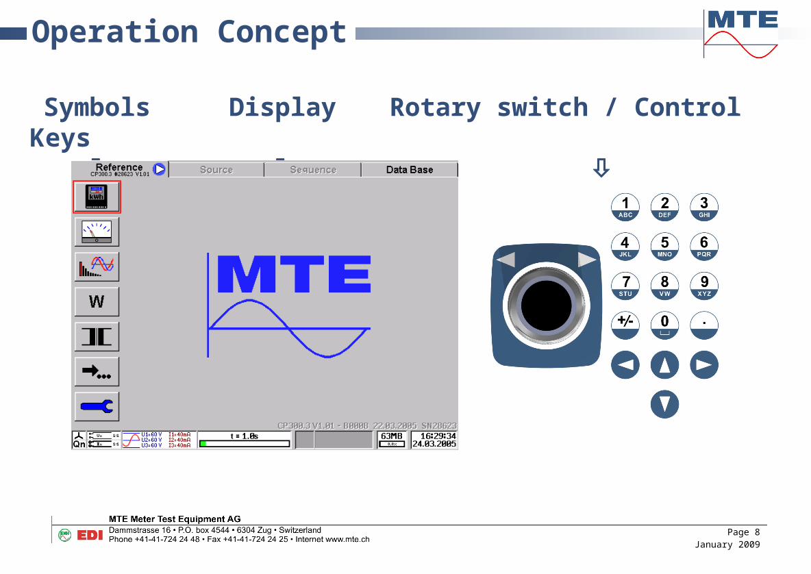
Operation Concept
Symbols Display Rotary switch / Control Keys
Page 8January 2009

SoftwareMain Menu
Meter Testing
Measurement
Harmonics, Oscilloscope
Energy Measurement
Transformer Test
Further Tests
Installation (Setup)
First Row
Page 9January 2009

SoftwareMeasurement – Basic Quantities
Measurement UI
Data storage
Second Row
Page 10January 2009

SoftwareMeasurement – Basic Quantities
Measurement PQS
Data storage
Second Row
Page 11January 2009

SoftwareMeasurement – Basic Quantities
Measurement UIPQS
Data storage
Second Row
Page 12January 2009

SoftwareMeasurement – Vector Diagram
Vector analysis
Data storage
Second Row
Page 13January 2009

SoftwareMeasurement – Oscilloscop
Selection of U
Selection of I
Data storage
Exit to previous menu
First Row
Page 14January 2009
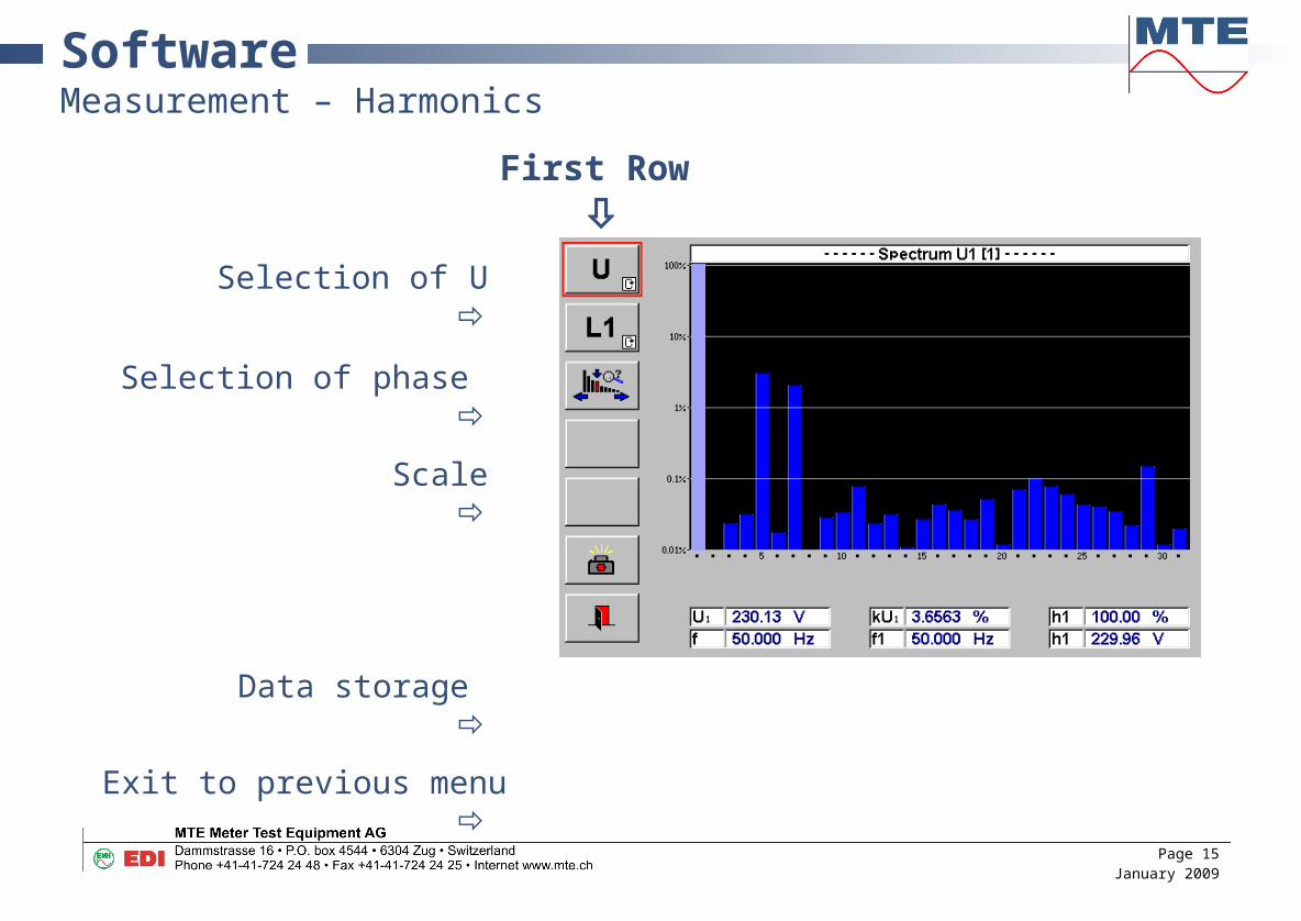
SoftwareMeasurement – Harmonics
Selection of U
Selection of phase
Scale
Data storage
Exit to previous menu
First Row
Page 15January 2009
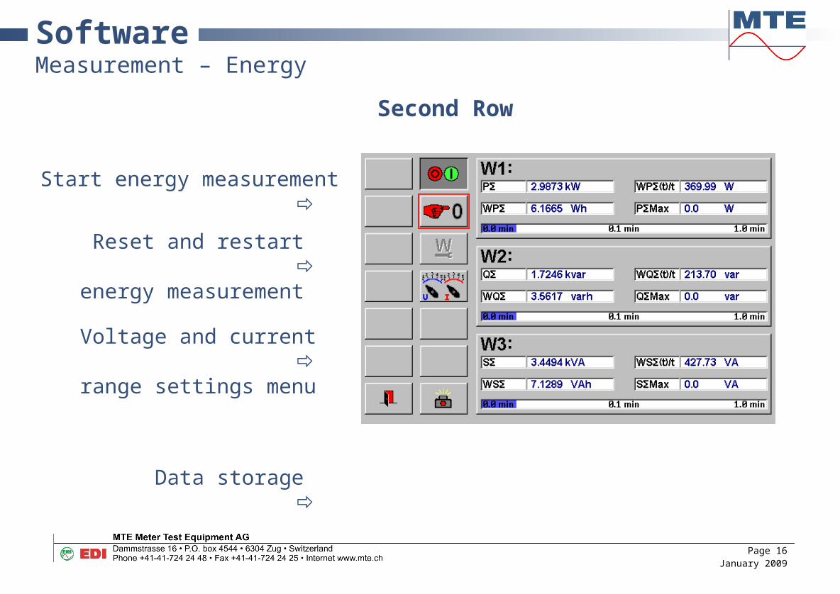
SoftwareMeasurement – Energy
Start energy measurement
Reset and restart
energy measurement
Voltage and current
range settings menu
Data storage
Second Row
Page 16January 2009

SoftwareMeasurement – Register test
Second Row
Start or stop register test
Enter counters before meas.
Enter counters after meas.
Reset register test
Setup register test
Range settings
Data storage
Page 17January 2009

SoftwareMeasurement – Voltage Burden
Selection of phase
Settings for voltage
burden measurement
Data storage
Exit to previous menu
First Row
Page 18January 2009

SoftwareMeasurement – Current Burden
Selection of phase
Settings for current
burden measurement
Data storage
Exit to previous menu
First Row
Page 19January 2009

SoftwareMeasurement – Voltage Transformer Ratio
Reference for voltage
ratio calculation
Definition of reference
NP or NS
Data storage
Exit to previous menu
First Row
Page 20January 2009

SoftwareMeasurement – Current Transformer Ratio
Reference for current
ratio calculation
Definition of reference
Data storage
Exit to previous menu
First Row
Page 21January 2009

SoftwareError measurement
Start/Stop error measurement
Restart of error measurement
Setup of error measurement
Data storage
Second Row
Page 22January 2009

SoftwareSpecial function – fRef Test
Input of reference frequency
Input of duration of test
Start fRef test
Data storage
Exit to previous menu
First Row
Page 23January 2009
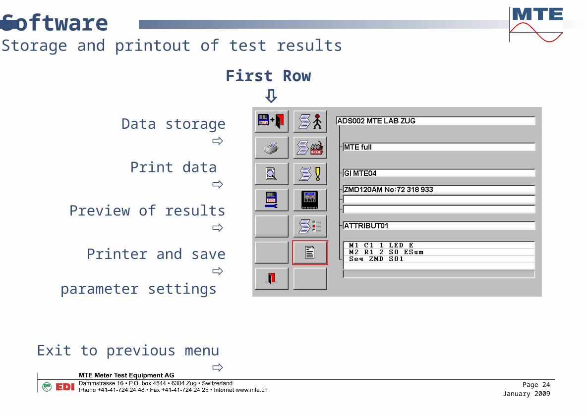
SoftwareStorage and printout of test results
Data storage
Print data
Preview of results
Printer and save
parameter settings
Exit to previous menu
First Row
Page 24January 2009

SoftwareStorage and printout of test results
Administrative data set
Customer data set
General info data set
Meter data sets
Other checks dataset
Comment
Second Row
Page 25January 2009

SoftwareStorage and printout of test results
Page 26January 2009

Connection exampleTesting of an installed direct connected 4-wire meter
Page 27January 2009

Connection exampleTesting of an direct connected 4-wire meter
Page 28January 2009

Connection exampleBurden measurement of voltage transformer
Page 29January 2009
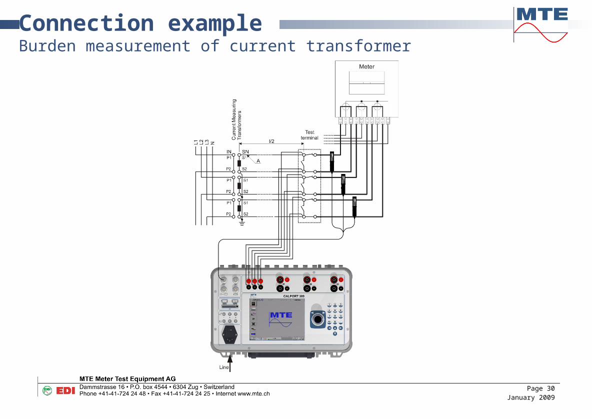
Connection exampleBurden measurement of current transformer
Page 30January 2009

Connection exampleMeasurement of transformer ratio
Page 31January 2009
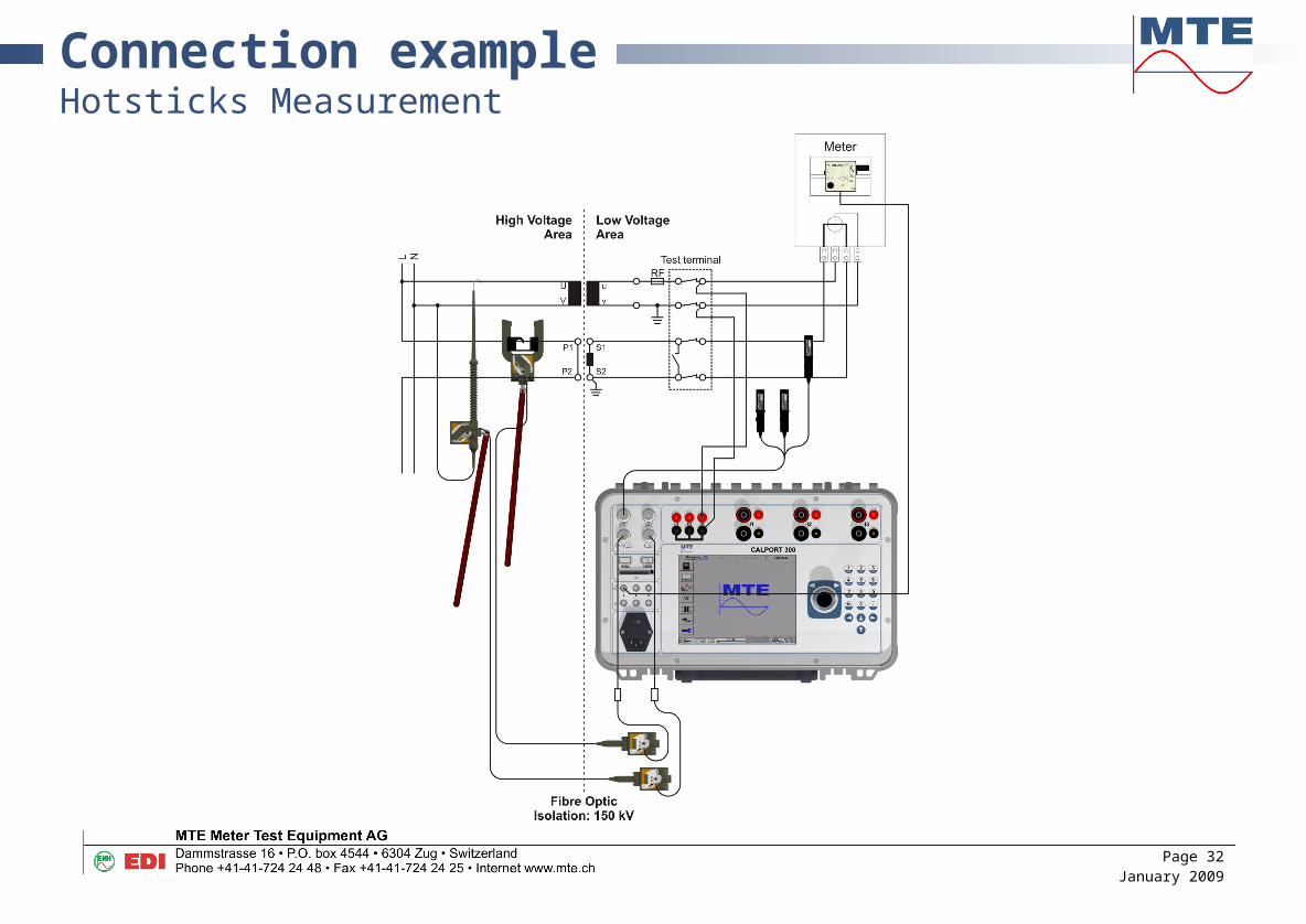
Connection exampleHotsticks Measurement
Page 32January 2009

Windows©-SoftwareCALSOFT
Selection of real time readoutorreadout of setsof data fromCALPORT 300 memory
Page 33January 2009

Windows©-SoftwareCALSOFT
Display of read data on PC monitor
Page 34January 2009