caltrans logging manual
TRANSCRIPT

8/9/2019 Caltrans Logging Manual
http://slidepdf.com/reader/full/caltrans-logging-manual 1/93
State of CaliforniaDepartment of TransportationDivision of Engineering ServicesGeotechnical Services
Soil and Rock Logging,
Classification, andPresentation Manual
June 2007
© 2007 Department of Transportation

8/9/2019 Caltrans Logging Manual
http://slidepdf.com/reader/full/caltrans-logging-manual 2/93
(This page left intentionally blank)

8/9/2019 Caltrans Logging Manual
http://slidepdf.com/reader/full/caltrans-logging-manual 3/93

8/9/2019 Caltrans Logging Manual
http://slidepdf.com/reader/full/caltrans-logging-manual 4/93
Acknowledgements
Geotechnical Services wishes to thank the following team members for preparing this Manual.
Roy Bibbens, Geotechnical Services
Mark Desalvatore, Geotechnical Services
Mark Hagy, Geotechnical Services
Craig Hannenian, Geotechnical Services
Deh-Jeng Jang, Geotechnical Services
Robert Price, Geotechnical Services
Loren Turner, Research & Innovation
Hector Valencia, Geotechnical Services
Thomas Whitman, Geotechnical Services
The team wishes to extend its appreciation to the following people and/ororganizations for their contributions to the content of this Manual.
Bruce Hilton, Kleinfelder Inc.
Mike Kennedy, Anderson Drilling Inc., Association of Drilled Shaft
Contractors
Mildred Macaranas, Geotechnical Services
Alan Macnab, Condon-Johnson & Associates, Association of Drilled
Shaft Contractors
Steve Mahnke, CA Dept. of Water ResourcesHeinrich Majewski, Malcolm Drilling Co. Inc., Association ofDrilled Shaft Contractors
Rick and Dot Nelson, Dot.Dat.Inc
Parsons Brinckerhoff
Ron Richman, Geotechnical Services
Barry Siel, Federal Highway Administration
Sarah Skeen, Federal Highway Administration
URS Corp.Will Smith, Case Pacific, Association of Drilled Shaft Contractors
(Names have been listed alphabetically.)
ii

8/9/2019 Caltrans Logging Manual
http://slidepdf.com/reader/full/caltrans-logging-manual 5/93
Table of Contents
SECTION 1: INTRODUCTION .......................................................................................................1
1.1 Intent of this Manual...............................................................................................................1
1.2 Limitations..............................................................................................................................1
1.3 Exceptions to Policy ...............................................................................................................1
1.4 Revisions to the Manual.........................................................................................................1
1.5 Organization of this Manual ...................................................................................................2
1.6 Overview of the Logging Process and Presentation Formats ................................................2
SECTION 2: FIELD PROCEDURES FOR SOIL AND ROCK LOGGING, DESCRIPTION, ANDIDENTIFICATION .............................................................................................................................5
2.1 Introduction ............................................................................................................................5
2.2 General Project and Hole Information....................................................................................5
2.3 Assignment of Hole Identification...........................................................................................7
2.4 Soil Description and Identification Procedures.......................................................................7
2.4.1 Soil Description and Identification ............................................................................................................8
2.4.2 Group Name and Group Symbol..............................................................................................................9
2.4.3 Consistency (Cohesive Soils) .................................................................................................................13
2.4.4 Apparent Density (Cohesionless Soils)..................................................................................................15
2.4.5 Color .......................................................................................................................................................15
2.4.6 Moisture..................................................................................................................................................15
2.4.7 Percent of Cobbles or Boulders .............................................................................................................15
2.4.8 Percent or Proportion of Soils ................................................................................................................16
2.4.9 Particle Size............................................................................................................................................16
2.4.10 Particle Angularity...................................................................................................................................17
2.4.11 Particle Shape .......................................................................................................................................17
2.4.12 Plasticity (for Fine-Grained Soils) ..........................................................................................................17
2.4.13 Dry Strength (for Fine-Grained Soils).....................................................................................................18
2.4.14 Dilatancy (for Fine-Grained Soils) .........................................................................................................18
2.4.15 Toughness (for Fine-Grained Soils) ......................................................................................................18
2.4.16 Structure .................................................................................................................................................18
2.4.17 Cementation ...........................................................................................................................................18
2.4.18 Description of Cobbles and Boulders....................................................................................................19
2.4.19 Additional Comments .............................................................................................................................19
2.4.20 Other Drilling Observations ....................................................................................................................19
2.5 Rock Identification Procedures for Borehole Cores..............................................................20
2.5.1 Rock Identification and Descriptive Sequence for Borehole Cores .......................................................20
2.5.2 Rock Name.............................................................................................................................................21
2.5.3 Rock Grain-size descriptors ...................................................................................................................23
2.5.4 Bedding Spacing Descriptors .................................................................................................................25
2.5.5 Rock Colors ............................................................................................................................................25
2.5.6 Textural Descriptors ...............................................................................................................................25
2.5.7 Weathering Descriptors for Intact Rock..................................................................................................26
2.5.8 Rock Hardness .......................................................................................................................................27
iii

8/9/2019 Caltrans Logging Manual
http://slidepdf.com/reader/full/caltrans-logging-manual 6/93
2.5.9 Fracture Density .....................................................................................................................................27
2.5.10
Discontinuity Type ..................................................................................................................................28
2.5.11
Discontinuity Condition (Weathering, Infilling and Healing) ...................................................................29
2.5.12 Discontinuity Dip Magnitude...................................................................................................................30
2.5.13 Rate of Slaking .......................................................................................................................................30
2.5.14 Odor........................................................................................................................................................30
2.5.15
Additional Comments .............................................................................................................................31
2.5.16
Other Drilling Observations ....................................................................................................................31
2.6 Sample Preparation and Identification for Laboratory Testing and Storage .........................32
2.6.1 Sample Preparation and Identification for Laboratory Testing and Storage ..........................................32
2.6.2 Identification of Large Soil Samples .......................................................................................................34
2.6.3 Core Box Layout.....................................................................................................................................37
2.7
Quality Check of Field Observations and Samples ..............................................................38
SECTION 3: PROCEDURES FOR SOIL AND ROCK DESCRIPTION AND/ORCLASSIFICATION USING LABORATORY TEST RESULTS .......................................................39
3.1 Introduction ..........................................................................................................................39
3.2 Revising Soil Descriptions and Assigning Soil Classification Using Laboratory Test Results
.............................................................................................................................................39
3.2.1 Soil Classification and Description Descriptive Sequence .....................................................................40
3.2.2 Group Name and Group Symbol............................................................................................................41
3.2.3
Consistency (Cohesive Soils).................................................................................................................46
3.2.4
Percent or Proportion of Soils ................................................................................................................46
3.2.5
Particle Size............................................................................................................................................46
3.2.6 Plasticity (for Fine-Grained Soils)...........................................................................................................46
3.3
Revising Rock Identification and Description for Borehole Cores Using Laboratory TestResults .................................................................................................................................47
3.3.1 Strength of Intact Rock ...........................................................................................................................47
SECTION 4: METHODS OF PRESENTATION OF SUBSURFACE INFORMATION..................49
4.1 Introduction ..........................................................................................................................49
4.2 Factual vs. Interpretive Subsurface Data .............................................................................49
4.3 Incorporating Laboratory Data, Refining Descriptions, and Classifying Soil.........................50
4.3.1 Subsurface Data Presentation Method ..................................................................................................50
4.3.2 General Rules and Considerations ........................................................................................................50
4.3.3 Example..................................................................................................................................................51
SECTION 5: BORING LOG AND LEGEND PRESENTATION FORMATS .................................53
5.1
Introduction ..........................................................................................................................53
5.2 Log of Test Boring................................................................................................................53
5.2.1 Contents and Characteristics of the LOTB............................................................................................54
5.2.2 Notes on the LOTB.................................................................................................................................54
5.2.3 LOTB Sheet Formatting..........................................................................................................................54
5.2.4 As-Built LOTB Sheet Formatting ............................................................................................................56
5.2.5 The LOTB Legend Sheets......................................................................................................................57
iv

8/9/2019 Caltrans Logging Manual
http://slidepdf.com/reader/full/caltrans-logging-manual 7/93
5.3 Boring Records ....................................................................................................................64
5.3.1 Content and Characteristics of the BR...................................................................................................67
5.3.2 Notes on the BR .....................................................................................................................................67
5.3.3 The Boring Record Legend Sheets ........................................................................................................67
REFERENCES ...............................................................................................................................71
APPENDIX A: FIELD TEST PROCEDURES ...............................................................................73
A.1 Pocket Penetrometer ...........................................................................................................73
A.2 Torvane................................................................................................................................73
A.3 Dry Strength.........................................................................................................................73
A.4 Dilatancy ..............................................................................................................................73
A.5 Toughness ...........................................................................................................................73
A.6 Jar Slake Index Test ............................................................................................................74
A.7 Calcium Carbonate ..............................................................................................................74
A.8 Standard Penetration Test ...................................................................................................74
A.9 Core Recovery (REC) ..........................................................................................................75
A.10 Rock Quality Designation (RQD)..........................................................................................75
APPENDIX B: FIELD LOGGING AIDS........................................................................................77
B.1 Field Sample Logging Forms ...............................................................................................77
APPENDIX C: PROCEDURAL DOCUMENTS ............................................................................81
v

8/9/2019 Caltrans Logging Manual
http://slidepdf.com/reader/full/caltrans-logging-manual 8/93
(This page left intentionally blank)
vi

8/9/2019 Caltrans Logging Manual
http://slidepdf.com/reader/full/caltrans-logging-manual 9/93
Section 1:Introduction
1.1 Intent of this Manual
The intent of this Manual is to define the
Department’s practices and procedures for soil androck description, identification, classification, and
preparation of boring logs.
Standardized terminology and consistent
presentation procedures for projects statewide benefit the Department’s staff, engineeringconsultants, bidders, and contractors. Geotechnical
Services staff as well as any other organization
providing geotechnical reports or records of
geotechnical investigations to the Department shallfollow the procedures presented in this Manual.
The following terms, as defined below, are usedthroughout this Manual to convey the
Department’s policy:
Term Definition
Shall,Required
Mandatory Standard. Theassociated provisions must beused. There is no acceptablealternative.
Should Advisory Standard. Theassociated provisions are preferredpractices.
May,Optional
Permissive Standard. Use orapplication of the associatedprovisions is left to the discretion ofthe Geoprofessional.
1.2 Limitations
Although this manual may be used to train new
employees, this is not its primary intent.This manual does not replace education or
experience and shall be used in conjunction with professional judgment. Not all aspects of this
manual may be applicable in all circumstances and
should be applied with consideration of a project’smany unique aspects.
This manual does not purport to address all of the
safety problems, if any, associated with its use. It isthe responsibility of the user of this standard to
establish, or adhere to, appropriate safety and
health practices and determine the applicability ofregulatory limitations prior to use. The reader shall
follow at a minimum, the Caltrans Code of Safe
Drilling Practices.
1.3 Exceptions to Policy
Exceptions to the policy and procedures set forth in
this Manual require prior approval by theGeotechnical Services Deputy Division Chief.
Staff shall use the procedure for obtaining approvalfor an exception, as documented in a memorandum
to all staff dated June 15, 2007, included in
Appendix C.
1.4 Revisions to the Manual
Staff who wish to propose changes to the Manual
shall do so in accordance with the Soil and Rock
Logging, Classification, and Presentation Manual
Committee Charter and Standard Procedures,
included in Appendix C.
Soil and Rock Logging, Classification, and Presentation Manual, Section 1 1

8/9/2019 Caltrans Logging Manual
http://slidepdf.com/reader/full/caltrans-logging-manual 10/93
1.5 Organization of this Manual
The Manual is divided into five sections, as
described below:
Section 1
– Explains the intent and organization of this
Manual and the process for requestingexceptions and proposing changes to theManual
– Presents an overview of the logging processand acceptable presentation formats
Section 2
– Presents the Department’s field description andindentification procedures for soil and rock,
without the benefit of laboratory testing
– Explains procedures for handling and labeling
of samples
–
Explains how to perform a quality check of borehole logs and soil and rock samples
Section 3
– Describes the Department’s classification
procedures for soil and rock samples for whichthe data was refined by appropriate laboratory
tests
Section 4
– Presents the process for developing and
presenting geotechnical information on a Logof Test Boring (LOTB) or a Boring Record
(BR).
Section 5
– Specifies presentation content and formats for Log of Test Boring (LOTB) and Boring Record
(BR).
1.6 Overview of the LoggingProcess and PresentationFormats
The Department uses the following formats to
present subsurface information:
• Log of Test Boring (LOTB), and/or
• Boring Record (BR).
An LOTB is typically associated with a structure
facility and is attached to Project Plans. A BR is
typically associated with an earthwork facility andis attached to a Geotechnical Report.
The process of creating boring logs, i.e., Log ofTest Boring (LOTB) and Boring Record (BR) can
be summarized in four steps:
• Field sampling and descriptions (Section 2)
• Quality check of field descriptions (Section 2)
• Refinement of descriptions, and classificationof soil, based on laboratory test results, if
performed (Section 3)
• Preparation of the boring logs (Sections 4
and 5)
(See Figure 1-1.)
Prior to the field investigation, the geoprofessionalshould have general understanding of the localsoils and geologic information, and know the
parameters and the basic descriptors required for
the planned analyses. Specific laboratory tests,
such as strength, consolidation, or permeabilitymay govern the type of drilling and sampling used.
Recovering and labeling, and accurately describingand classifying samples is a detailed process that
typically necessitates a thorough check of field
notes and samples in the office before requesting
laboratory tests. In some cases, the geoprofessionalmay use only field observations. (See Section 2.)
In other cases, it may be the judgment of thegeoprofessional that a combination of field
observations and laboratory test results are needed
to describe or classify the soil or rock samples, andgenerate appropriate layer descriptions for LOTB
or BR. (See Sections 2
and 3.)
Soil and Rock Logging, Classification, and Presentation Manual, Section 1 2

8/9/2019 Caltrans Logging Manual
http://slidepdf.com/reader/full/caltrans-logging-manual 11/93
If the results of laboratory tests change thedescription of the sample generated by field
observation, the classification and/or description
resulting from the laboratory tests shall be used onthe LOTB and/or the BR, and in the geotechnical
report. Disclosure of the tests on the LOTB and/or
the BR makes it clear whether the sample or layer
descriptor was based on visual observation or onlaboratory test results. (See Sections 4 and 5.)
Figure 1-1Logging and Presentation Process
FieldSamplingandDescriptions
(Sec. 2)
QualityCheck ofFieldObservations(Sec. 2)
LaboratoryTests?
YES NO
IncorporateLaboratory Data,RefineDescriptions, andClassify (Sec. 3)
PrepareBoring Logs(Sec. 4 & 5)
Soil and Rock Logging, Classification, and Presentation Manual, Section 1 3

8/9/2019 Caltrans Logging Manual
http://slidepdf.com/reader/full/caltrans-logging-manual 12/93
(This page left intentionally blank)
Soil and Rock Logging, Classification, and Presentation Manual, Section 1 4

8/9/2019 Caltrans Logging Manual
http://slidepdf.com/reader/full/caltrans-logging-manual 13/93
Section 2:Field Procedures for Soil and Rock Logging, Descript ion,and Identification
2.1 Introduction
This section presents the procedures for logging,describing, and identifying soil and rock samples
in the field based on visual and manual procedures.
The information presented in this section is
predominantly based on:
• American Society for Testing and Materials(ASTM) D 2488-06, Standard Practice for
Description and Identification of Soils (Visual-
Manual Procedure), and
• The Engineering Geology Field Manual
published by the Bureau of Reclamation.
Although ASTM D 2488-06 provides a
standardized method for indentification of soils, itdoes not provide adequate descriptive terminology
and criteria for identifying soils for engineering
purposes. Section 17 of ASTM D 2488-06 states,
“this practice provides qualitative information
only,” and Note 4 adds, “The ability to describe
and identify soils correctly … may also be
acquired systematically by comparing numerical
laboratory test results for typical soils of each type
with their visual and manual characteristics.”
This Manual extends, and in some cases modifies,the ASTM standard to include additional
descriptive terms and criteria. It is not our intent toreplace the ASTM standards but to build on them,
and make them better understood.
The identifications and descriptions in the fieldlogs may be corrected, calibrated, or verified later based on laboratory test results of selected soil
samples to develop the final boring logs, as
described in Section 3.
The process of correction, calibration, andverification in developing the updated logs based
on laboratory test results can effectively serve the purpose of self-training and self-calibration for
future field identification and description of soil
samples.
In addition to soil and rock identification and
description, this section contains instructions that
describe proper hole and sample identification practices, and minimum material requirements for
various laboratory tests.
2.2 General Project and HoleInformation
One of the most important aspects of field work is
properly identifying the location of the project site,
drilling tools and methods used, and the personnelinvolved in the field work. Figure 2-1 presents the
information that is required to be recorded forevery hole.
Soil and Rock Logging, Classification, and Presentation Manual, Section 2 5

8/9/2019 Caltrans Logging Manual
http://slidepdf.com/reader/full/caltrans-logging-manual 14/93
Figure 2-1Information Required for Borehole
Item Description
1 Date(s) of work
2 Hole Identification
3 Project and Site Information:
• Project Name
• Structure/Bridge Name and Number (if available)
• Project Number (Charge District - Expenditure Authorization, 8-digits)
• District
• County
• Route
• Postmile, range and prefix
4 Borehole Location and Elevation:
• Location (at least one of the following):
o Station and offset
o Latitude and longitude, horizontal datum
o Northing and Easting, local coordinate reference system
Note: In the absence of accurate coordinate data, a suitable and verifiable field description may betemporarily used. (e.g., postmile and centerline offset, distance to fixed object or benchmark, etc.)
•
Elevation, vertical datum, benchmark description
• Survey method(s) used, approximate accuracy
5 Personnel:
• Logger/Geoprofessional
• Drillers
6 Drilling and Sampling Equipment (verify with Driller):
• Drill rig (manufacturer and model, and Caltrans Equipment Identification number)
•
Drilling method (mud rotary, air rotary, solid auger, hollow stem auger. etc.)
• Drill rod description (type, diameter)
• Drill bit description
• Casing (type, diameter) and installation depth
• SPT Hammer Type: Safety/Automatic Hammer, etc.
o Lifting mechanism (for safety hammer)
o Manufacturer & model
o Caltrans Equipment Identification number
o
Measured SPT energy efficiency ratio (if available)
• Type of sampler(s) and size(s)
o Undisturbed Shelby tube
o Undisturbed Piston
o Split spoon (e.g. SPT, Cal Mod, etc.)
o Core (both rock and soil)
o Disturbed (include auger cuttings)
o Other
7 Groundwater
• Method (observed while drilling, measured in hole, etc.)
• Date, time, and depth of each reading
8 Hole Completion
• Cause of termination (e.g., drilled to depth, refusal, early termination of traffic control, etc.)
• Abandonment (e.g., grout, soil cuttings, dry bentonite chips, piezometers installed, slope inclinometerinstalled, TDR, instrumentation, etc.)
Soil and Rock Logging, Classification, and Presentation Manual, Section 2 6

8/9/2019 Caltrans Logging Manual
http://slidepdf.com/reader/full/caltrans-logging-manual 15/93
2.3 Assignment of HoleIdentification
Holes shall be identified using the followingconvention:
HHH – YY – NNN
Where: HHH: The Hole Type or Sounding Codes
defined in Figure 2-2, which generally
follow ASTM D 6453-99
YY: 2-digit year
NNN: 3-digit number (001-199)
The numbers 001–099 are reserved for holesused to produce a foundation report; numbers
101–199 are reserved for holes used to producea geotechnical design report.
The YY-NNN component of the hole identification
is unique and matched to a Caltrans projectexpenditure authorization number (EA), not to a
site, structure, or bridge number. If two drilling
methods are used, such as auger boring followed by rotary drilled boring, the prominent tool governs
the selection of Hole Type Code (HHH).
Figure 2-2Hole Type Code and Descr iption
2.4 Soil Description andIdentification Procedures
This section presents the method for identificationand description of soil based on ASTM D 2488-06
and USBR (2001). The detail of description
provided for a particular soil should be dictated by
the complexity and objectives of the project.Optional descriptors should be considered by thegeoprofessional on a project by project basis.
Hole Type
Code Description
A Auger boring (hollow or solid stem,bucket)
RRotary drilled boring (both conventionaland wire-line)
P Rotary percussion boring (Air)
HD Hand driven (1-inch soil tube)
HA Hand auger
D Driven (dynamic cone penetrometer)
CPT Cone Penetration Test
O Other
Soil and Rock Logging, Classification, and Presentation Manual, Section 2 7

8/9/2019 Caltrans Logging Manual
http://slidepdf.com/reader/full/caltrans-logging-manual 16/93
2.4.1 Soil Description and Identification
When describing and identifying soil in the field,
the geoprofessional shall record the field datafollowing the sequence presented in Figure 2-3
below. Items marked “required” shall be used,
when applicable, to describe the soil sample toensure complete descriptive coverage. For
example, percent cobbles and/or boulders is onlyrequired if cobbles and/or boulders are encountered.
Figure 2-3
Identification and Description Sequence
S e q u e n c e
IdentificationComponents R
e f e r t o S e c t i o n
R e q u i r e d
O p t i o n a l
1 Group Name 2.4.2 J
2 Group Symbol 2.4.2 J
DescriptionComponents
3Consistency(for cohesive soils)
2.4.3 J
4 Apparent Density(for cohesionless soils)
2.4.4 J
5 Color (in moist condition) 2.4.5 J
6 Moisture 2.4.6 J
7Percent of cobbles orboulders
2.4.7 J
8 Percent or proportion of soils 2.4.8 J
9 Particle Size Range 2.4.9 J
10 Particle Angularity 2.4.10 EE
11 Particle Shape 2.4.11 EE
12Plasticity(for fine-grained soils)
2.4.12 J
13Dry Strength(for fine-grained soils)
2.4.13 EE
14Dilatency(for fine-grained soils)
2.4.14 EE
15Toughness(for fine-grained soils)
2.4.15 EE
16 Structure 2.4.16EE
17 Cementation 2.4.17 J
18Description of Cobbles andBoulders
2.4.18 J
19 Additional Comments 2.4.19 EE
Below are some examples that illustrate the
application of the descriptive sequence based onfield procedures.
Example of a complete descriptive sequence for a
sample using required and optional components:
Well-graded SAND with GRAVEL (SW),
medium dense, brown to light gray, wet, about
20% coarse subrounded to rounded flat and
elongated GRAVEL, about 75% coarse to fine
rounded SAND, about 5% fines, weak
cementation.
Example of a complete descriptive sequence for a
soil sample using only required components:
Well-graded SAND with GRAVEL (SW),
medium dense, brown to light gray, wet, little
coarse GRAVEL, mostly coarse to fine SAND,
few fines, weak cementation.
Example of a complete descriptive sequence that
omits the percent or proportion of the primary soil
constituent, which may be used when the percentage or proportion of the primary soil
constituent can be clearly inferred:
Well-graded SAND with GRAVEL (SW),
medium dense, brown to light gray, wet, little
coarse GRAVEL, few fines, weak cementation.
2.4.1.1 Soil Description for IntenselyWeathered or Decomposed Rock
Intensely weathered or decomposed rock that isfriable and that can be reduced to gravel size orsmaller by normal hand pressure shall be identified
and described as rock followed by the soilidentification or classification, and description in
parenthesis (per Section 2.5).
Soil and Rock Logging, Classification, and Presentation Manual, Section 2 8

8/9/2019 Caltrans Logging Manual
http://slidepdf.com/reader/full/caltrans-logging-manual 17/93
2.4.2 Group Name and Group Symbol
Using visual examination and simple manual tests,
this section provides standardized criteria and procedures for describing and identifying soil in
the field per ASTM D 2488-06. The soil is to be
identified by assigning a group name and symbol.The Figures in this section are to be used for the
identification of both fine and coarse-grained soiland to determine the appropriate group symbol(s)
and name(s) to be used.
The ASTM procedure for identifying and
describing fine-grained and coarse-grained soils isonly applicable to material passing the 3-inch sieve.
If the presence of cobbles or boulders or both isidentified during the site exploration, the
percentage of cobbles and boulders shall be
estimated and reported per Section 2.4.7.
Borderline Symbol – Because ASTM D 2488-06 is based on estimates of particle size distribution and
plasticity characteristics, it may be difficult toclearly identify the soil as belonging to one
category. To indicate that the soil may fall into one
of two possible basic groups, a borderline symbolshall be used with the two symbols separated by a
slash. For example: SC/CL or CL/CH.
A borderline symbol shall be used when:
• The percentage of fines is estimated to be
between 45 and 55%. One symbol shall be for acoarse-grained soil with fines; the other for a
fine-grained soil, e.g., GM/ML or CL/SC.
• The percentage of sand and the percentage of
gravel are estimated to be about the same, e.g.,GP/SP, SC/GC, GM/SM.
• The soil could be well graded or poorly graded,e.g., GW/GP, SW/SP.
• The soil could either be a silt or a clay, e.g.,CL/ML, CH/MH, SC/SM.
• A fine-grained soil has properties that indicatethat it is at the boundary between a soil of low
plasticity and a soil of high plasticity, e.g.,CL/CH, MH/ML.
The order of the borderline symbols shall reflect
similarity to surrounding or adjacent soils. Forexample, soils in a borrow area have been
identified as CH, and one sample is considered to
have a borderline symbol of CL and CH. To showsimilarity, the borderline symbol shall be CH/CL.
The group name for a soil with a borderline symbolshall be the group name for the first symbol, except
for:• CL/CH lean to fat clay,
• ML/CL clayey silt, and
• CL/ML silty clay
Borderline symbols should not be used
indiscriminately. Use of a single group symbol is preferable.
Dual Symbol – A dual symbol is two symbols
separated by a hyphen, e.g., GP-GM, SW-SC, CL-
ML. They are used to indicate that the soil has beenidentified as having the properties of a
classification in accordance with ASTM TestMethod D 2487-06 requiring dual symbols, i.e.,
when the soil has between 5 and 12% fines, or
when the liquid limit and plasticity index values plot in the CL-ML area of the plasticity chart.
Soil and Rock Logging, Classification, and Presentation Manual, Section 2 9

8/9/2019 Caltrans Logging Manual
http://slidepdf.com/reader/full/caltrans-logging-manual 18/93
2.4.2.1 Fine Grained Soils
A soil is considered to be fine-grained if it contains 50% or more fines. Particles that pass through a Number
200 sieve are defined as fine-grained. Fine-grained soils shall be assigned the Group Name and Symbolaccording to Figure 2-4, below.
Figure 2-4
Flow chart for fine-grained soils (from ASTM D 2488-06)
G r o u p
S y m b o l
Fines Coarseness Sand or Gravel Group Name
CL
<30% plus No.200
<15% plus No.200 Lean CLAY
15-25% plus No.200% sand > % gravel Lean CLAY with SAND
% sand < % gravel Lean CLAY with GRAVEL
>30% plus No.200
% sand > % gravel< 15% gravel SANDY lean CLAY
> 15% gravel SANDY lean CLAY with GRAVEL
% sand < % gravel< 15% sand GRAVELLY lean CLAY
> 15% sand GRAVELLY lean CLAY with SAND
ML
<30% plus No.200<15% plus No.200 SILT
15-25% plus No.200% sand > % gravel SILT with SAND
% sand < % gravel SILT with GRAVEL
>30% plus No.200
% sand > % gravel< 15% gravel SANDY SILT
> 15% gravel SANDY SILT with GRAVEL
% sand < % gravel< 15% sand GRAVELLY SILT
> 15% sand GRAVELLY SILT with SAND
CH
<30% plus No.200
<15% plus No.200 Fat CLAY
15-25% plus No.200% sand > % gravel Fat CLAY with SAND
% sand < % gravel Fat CLAY with GRAVEL
>30% plus No.200
% sand > % gravel< 15% gravel SANDY fat CLAY
> 15% gravel SANDY fat CLAY with GRAVEL
% sand < % gravel< 15% sand GRAVELLY fat CLAY
> 15% sand GRAVELLY fat CLAY with SAND
MH
<30% plus No.200
<15% plus No.200 Elastic SILT
15-25% plus No.200% sand > % gravel Elastic SILT with SAND
% sand < % gravel Elastic SILT with GRAVEL
>30% plus No.200
% sand > % gravel< 15% gravel SANDY elastic SILT
> 15% gravel SANDY elastic SILT with GRAVEL
% sand < % gravel< 15% sand GRAVELLY elastic SILT
> 15% sand GRAVELLY elastic SILT with SAND
OL/OH
<30% plus No.200
<15% plus No.200 ORGANIC SOIL
15-25% plus No.200% sand > % gravel ORGANIC SOIL with SAND
% sand < % gravel ORGANIC SOIL with GRAVEL
>30% plus No.200
% sand > % gravel< 15% gravel SANDY ORGANIC SOIL
> 15% gravelSANDY ORGANIC SOIL withGRAVEL
% sand < % gravel< 15% sand GRAVELLY ORGANIC SOIL
> 15% sandGRAVELLY ORGANIC SOIL withSAND
Soil and Rock Logging, Classification, and Presentation Manual, Section 2 10

8/9/2019 Caltrans Logging Manual
http://slidepdf.com/reader/full/caltrans-logging-manual 19/93
Clay and Silt – Identify the soil as a Lean CLAY (CL), a Fat CLAY (CH), a SILT (ML), or an Elastic SILT
(MH), using the criteria in Figure 2-5:
Figure 2-5
Identification of clayey and silty soils
Group Symbol Dry Strength Dilatancy Toughness
ML None to low Slow to rapid Low or thread cannot be formed
CL Medium to high None to slow Medium
MH Low to medium None to slow Low to medium
CH High to very high None High
Organic Soil – Identify the soil as organic, OL/OH, if the soil contains enough organic particles to influence
the soil properties. Organic soils usually have a dark brown to black color and may have an organic odor.
Often, organic soils will change color, for example, black to brown, when exposed to the air. Some organicsoils will lighten in color significantly when air-dried. Organic soils normally will not have a high toughness
or plasticity. The thread for the toughness test will be spongy.
Identification of Peat – A sample composed primarily of vegetable tissue in various stages of decompositionthat has a fibrous to amorphous texture, usually a dark brown to black color, and an organic odor, shall be
designated as a highly organic soil and shall be identified with the Group Name and Symbol, PEAT (PT),
and not subjected to the identification procedures described hereafter.
Soil and Rock Logging, Classification, and Presentation Manual, Section 2 11

8/9/2019 Caltrans Logging Manual
http://slidepdf.com/reader/full/caltrans-logging-manual 20/93
2.4.2.2 Coarse-Grained Soil
A soil is considered coarse-grained if it contains fewer than 50% fines. (Coarse-grain particles will not pass
through a Number 200 sieve.) Soil is identified as gravel if the percentage of gravel is estimated to be greaterthan the percentage of sand. Soil is identified as sand if the percentage of gravel is estimated to be equal to or
less than the percentage of sand.
Soil and Rock Logging, Classification, and Presentation Manual, Section 2 12

8/9/2019 Caltrans Logging Manual
http://slidepdf.com/reader/full/caltrans-logging-manual 21/93

8/9/2019 Caltrans Logging Manual
http://slidepdf.com/reader/full/caltrans-logging-manual 22/93
Use the terms and criteria indicated in Figure 2-8 below to describe the consistency of cohesive soils. These
terms generally follow, with some modifications, AASHTO (1988) and Bureau of Reclamation (2001)standards.
Figure 2-8
Descripto rs for Consistency of Cohesive Soils
Description
PenetrometerMeasurement (tsf)
TorvaneMeasurement (ts f) Field Approximation
Very Soft < 0.25 < 0.12 Easily penetrated several inches by fist
Soft 0.25 to 0.50 0.12 to 0.25 Easily penetrated several inches by thumb
Medium Stiff 0.50 to 1.0 0.25 to 0.50 Can be penetrated several inches by thumbwith moderate effort
Stiff 1 to 2 0.50 to 1.0 Readily indented by thumb but penetrated onlywith great effort
Very Stiff 2 to 4 1.0 to 2.0 Readily indented by thumbnail
Hard > 4.0 > 2.0 Indented by thumbnail with difficulty
Soil and Rock Logging, Classification, and Presentation Manual, Section 2 14

8/9/2019 Caltrans Logging Manual
http://slidepdf.com/reader/full/caltrans-logging-manual 23/93
2.4.4 Apparent Densi ty (Cohesionless 2.4.6 MoistureSoils)
Use the AASHTO (1988) standards to describe the
apparent density of cohesionless soils, as indicatedin Figure 2-9 below.
Figure 2-9
Descripto rs fo r Apparent Densityof Cohesionless Soils
Description SPT N60 (blows/ft)
Very loose 0 – 4
Loose 5 – 10
Medium dense 11 – 30
Dense 31 – 50
Very dense >50
Apparent density of a coarse-grained (cohesionless)
soil is based on a corrected Standard PenetrationTest (SPT) N60 value as described in Appendix A
and provided here:
N 60 = N measured X (ERi /60)
where,
ERi = Hammer energy ratio
N values are highly dependent on the energy
efficiency of the SPT method. Inconsistency in the N values across a site may be attributed to
variations in energy efficiency between different
drill rigs and crews.
2.4.5 Color
Color is an important property in identifying
organic soils, and it may also be useful inidentifying materials of similar geologic origin
within a given locality. Use the color name from
the Munsell Color System to describe the color of amoist soil sample at the time of drilling and
sampling. If the sample contains layers or patchesof varying colors, record this information and
describe all observed colors. For example:
Brown to light yellowish brown
For additional information, see ASTM D 1535-06,
Standard Practice for Specifying Color by the
Munsell System.
Use the ASTM D 2488-06 standard to describe the
moisture condition, as indicated inFigure 2-10 below.
Figure 2-10Descriptors for Moisture
Description Criteria
Dry Absence of moisture, dusty,dry to the touch
Moist Damp but no visible water
Wet Visible free water, usually soilis below water table
2.4.7 Percent of Cobbles or Boulders
When particles greater than 3 inches in diameter
are encountered, they shall be identified and
described as “COBBLES,” or “BOULDERS,” or“COBBLES and BOULDERS” as defined in
Section 2.4.9. Cobbles and boulders reported as present within a matrix shall be estimated, by
volume, and reported by percentage of total
volume.
Estimation of volume of cobbles and/or boulders is
based upon recovered intersected lengths, drilling
chatter, and observations and experience of thedriller and/or geoprofessional.
A subset of rock descriptors shall be used todescribe cobbles and boulders as explained inSection 2.4.18. Isolated boulders may be treated as
individual units and described as such.
For example, if it is estimated that 40% by volume
of the material is cobbles, describe the sample inthis way:
Well-graded SAND with GRAVEL and
COBBLES (SW), medium dense, brown to light
gray, wet, about 40% COBBLES, about 20%
coarse subrounded to rounded flat andelongated GRAVEL, about 75% coarse to fine
rounded SAND, about 5% fines, weak
cementation; COBBLES consist of sandstone,
fresh, hard, intersecting lengths from 8 to 10
inches.
Note, the percentages of constituents in the
example do not add up to 100%., as cobbles are
estimated by total volume, whereas gravel, sand,
Soil and Rock Logging, Classification, and Presentation Manual, Section 2 15

8/9/2019 Caltrans Logging Manual
http://slidepdf.com/reader/full/caltrans-logging-manual 24/93
and fines, are estimated by weight of the total
sample excluding the cobbles and boulders, perSection 2.4.8
If the sample or layer is estimated to be more than
50% cobbles and/or boulders by volume, the layer
shall be described as “COBBLES” or“BOULDERS” or “COBBLES and BOULDERS”
with the soil matrix description following. Note,this is a departure from the descriptive sequence in
Section 2.4.1. For example, if it is estimated that
60% by volume of the material was cobbles,describe the layer as:
COBBLES with some well-graded SAND with
GRAVEL, about 60% COBBLES (sandstone,
fresh, hard, intersecting lengths from 8 to 10
inches), matrix consists of medium dense,
brown to light gray, wet, about 20% coarse
subrounded to rounded flat and elongatedGRAVEL, about 75% coarse to fine rounded
SAND, about 5% fines, weak cementation.
Note that the Group Symbol is not used in the last
example, because the cobbles and boulders werethe predominant material.
2.4.8 Percent or Proportion of Soils
Use the ASTM D 2488-06 standard to describe the
estimated percentage (to the nearest 5%) or proportion of gravel, sand, and fines, by weight of
the total sample excluding the cobbles and boulders,as shown in Figure 2-11, below.
Figure 2-11Descriptors for percent or proportion of soils
removed if the percentage was revised based on
laboratory particle size analysis results.)
2.4.9 Particle Size
Use the ASTM D 2488-06 standard to describe thesize of particles, as shown in Figure 2-12, below.
Figure 2-12Descriptors for Particle Size
Description SizeFamiliarExample
Boulder >12 in. Larger than abasketball
Cobble 3 to 12 in. Larger than agrapefruit ororange
Coarse 3/4 to 3 in. Larger than a
Gravel walnut or grape
Fine Gravel No. 4 to 3/4 in. Larger than a pea
Coarse Sand No. 10 to No. 4 Larger than rocksalt grain
Medium Sand No. 40 to No. 10 Larger thanopenings of awindow screen
Fine Sand No. 200 to No. 40 Larger than asugar grain
Description Criteria
Trace Particles are present butestimated to be less than 5%
Few 5 to 10%
Little 15 to 25%Some 30 to 45%
Mostly 50 to 100%
The percentages of gravel, sand, and fines must
add up to 100 %. The term “about” shall be used ifthe percentage or proportion of constituents is
estimated in the field. (The word “about” shall be
Soil and Rock Logging, Classification, and Presentation Manual, Section 2 16

8/9/2019 Caltrans Logging Manual
http://slidepdf.com/reader/full/caltrans-logging-manual 25/93
2.4.10 Particle Angularity
Use the ASTM D 2488-06 standard to describe the
angularity of the sand (coarse sizes only), gravel,cobbles, and boulders, as indicated in Figure 2-13
below.
Figure 2-13
Descriptors for particle angularity
Description Criteria
Angular Particles have sharp edges andrelatively plane sides withunpolished surfaces
Subangular Particles are similar to angulardescription, but have roundededges
Subrounded Particles have nearly plane sides,but have well-rounded corners andedges
Rounded Particles have smoothly curvedsides and no edges
Rounded Angular
Subrounded Subangular
2.4.11 Particle Shape
Use the ASTM D 2488-06 standard to describe theshape of the gravel, cobbles, and boulders if they
meet any of the criteria in Figure 2-14.
The particle shape shall be described as follows
where length, width, and thickness refer to thegreatest, intermediate, and least dimensions of a particle, respectively.
Figure 2-14Descriptors for Particle Shape
Description Criteria
Flat Particles with width/thickness > 3
Elongated Particles with length/width > 3
Flat and
Elongated
Particles meet criteria for both flat
and elongated
2.4.12 Plasticity (for Fine-Grained Soils)
Use the ASTM D 2488-06 standard to describe the
plasticity of the material based on observationsmade during the toughness test, as indicated in
Figure 2-15 below.
Figure 2-15
Descriptors for Plasticity
Description Criteria
Nonplastic A 1 ⁄ 8-in. thread cannot be rolled atany water content.
Low The thread can barely be rolled andthe lump cannot be formed whendrier than the plastic limit.
Medium The thread is easy to roll and notmuch time is required to reach theplastic limit. The thread cannot bererolled after reaching the plasticlimit. The lump crumbles when drierthan the plastic limit.
High It takes considerable time rollingand kneading to reach the plasticlimit. The thread can be rerolledseveral times after reaching theplastic limit. The lump can be formedwithout crumbling when drier than theplastic limit.
Soil and Rock Logging, Classification, and Presentation Manual, Section 2 17

8/9/2019 Caltrans Logging Manual
http://slidepdf.com/reader/full/caltrans-logging-manual 26/93
2.4.13 Dry Strength (for Fine-Grained Soi ls)
Use the ASTM D 2488-06 standard to determine
dry strength, as indicated in Figure 2-16 below.(See Appendix A for details on field test
procedures.)
Figure 2-16
Descriptors for Dry StrengthDescription Criteria
None The dry specimen crumbles intopowder with mere pressure of handling.
Low The dry specimen crumbles intopowder with some finger pressure.
Medium The dry specimen breaks into pieces orcrumbles with considerable fingerpressure
High The dry specimen cannot be brokenwith finger pressure. Specimen will
break into pieces between thumb and ahard surface.
Very High The dry specimen cannot be brokenbetween the thumb and a hard surface.
2.4.14 Dilatancy (for Fine-Grained Soils)
Use the ASTM D 2488-06 standard to determine
dilatancy, as indicated in Figure 2-17 below. (See
Appendix A for details on field test procedures.)
Figure 2-17
Descriptors for di latancy
Description Criteria
None No visible change in the specimen
Slow Water appears slowly on the surfaceof the specimen during shaking anddoes not disappear or disappearsslowly upon squeezing
Rapid Water appears quickly on the surfaceof the specimen during shaking anddisappears quickly upon squeezing
2.4.15 Toughness (for Fine-Grained Soils)
Use the ASTM D 2488-06 standard to determine
toughness, as indicated in Figure 2-18 below. (See
Appendix A for details on field test procedures.)
Figure 2-18
Descriptors for toughness
Description Criteria
Low Only slight pressure is required to rollthe thread near the plastic limit. Thethread and the lump are weak and soft.
Medium Medium pressure is required to roll thethread to near the plastic limit. Thethread and the lump have mediumstiffness.
High Considerable pressure is required toroll the thread to near the plastic limit.The thread and the lump have veryhigh stiffness
2.4.16 Structure
Use the ASTM D 2488-06 standard to describe the
structure of intact soils, as indicated in Figure 2-19
below.
Figure 2-19
Descriptors for structu re
Description Criteria
Stratified Alternating layers of varyingmaterial or color with layers at least¼ in. thick; note thickness.
Laminated Alternating layers of varyingmaterial or color with the layers lessthan ¼ in. thick; note thickness.
Fissured Breaks along definite planes offracture with little resistance tofracturing.
Slickensided Fracture planes appear polished orglossy, sometimes striated.
Blocky Cohesive soil that can be brokendown into small angular lumpswhich resist further breakdown.
Lensed Inclusion of small pockets ofdifferent soils, such as small lensesof sand scattered through a mass ofclay; note thickness.
Homogeneous Same color and appearancethroughout.
2.4.17 Cementation
Use the ASTM D 2488-06 standard to describe thecementation of intact coarse-grained soils, as
indicated in Figure 2-20 below.
Soil and Rock Logging, Classification, and Presentation Manual, Section 2 18

8/9/2019 Caltrans Logging Manual
http://slidepdf.com/reader/full/caltrans-logging-manual 27/93
Figure 2-20
Descriptors for cementation
Description Criteria
Weak Crumbles or breaks with handling orlittle finger pressure.
Moderate Crumbles or breaks with
considerable finger pressure.Strong Will not crumble or break with finger
pressure.
2.4.18 Descr ipt ion of Cobblesand Boulders
Use the descriptive sequence for rock in Section
2.5. of this Manual to describe cobbles and boulders. The description shall include, at
minimum, the following information:
•
Rock identification• Weathering
• Rock hardness
• Range of intersected lengths of core (An
“intersected length” is the length of the intactcore. This is not necessarily the size of the
cobble or boulder.)
2.4.19 Additional Comments
Additional constituents and soil characteristics not
included in the previous categories may be noted.Observations may include:
• Presence of roots or root holes
• Presence of mica, gypsum, etc.
• Presence of voids
• Surface coatings on coarse-grained particles
• Oxide staining
• Cementing agents (e.g. calcium carbonate – see
Appendix A.7)
•
Odor• Depositional history (i.e. Alluvium, Colluvium,
Aeolian, Lacustrine, Fill)
• Geologic formation name or soil survey unitname
All soils shall be examined to see if they contain
materials indicative of man-made fills. Man-madefill items shall be listed in each of the soil
descriptions. Common fill indicators include glass,
brick, clay pipe, dimensioned lumber, concrete
debris, in-place pavement sections, asphalt debris,metal, plastics, plaster, etc. Other items that may
suggest fill include buried vegetation mats, tree
limbs, stumps, etc.
The size and distribution of fill indicators shall benoted. The limits (depth range) of fill material shall
be determined and identified at each explorationlocation.
2.4.20 Other Drilling Observations
Other observations, not included in the descriptive
sequence, may include:
• Caving or sloughing of borehole or trench sides
• Difficulty in drilling or excavating, etc.
• Generic name (e.g., hard pan, fault gouge, etc.)
•
Ground water inflow, elevation(s), andestimated rate(s)
• Loss of drill fluid circulation
Soil and Rock Logging, Classification, and Presentation Manual, Section 2 19

8/9/2019 Caltrans Logging Manual
http://slidepdf.com/reader/full/caltrans-logging-manual 28/93
2.5 Rock Identif ication Proceduresfor Borehole Cores
Rock identification procedures presented in thissection are based on a hybrid of the International
Society of Rock Mechanics (ISRM) (1981)
standards and the Bureau of Reclamation (2001)
standards. The detail of description provided for a particular material shall be dictated by thecomplexity and objectives of the project. Optional
descriptors should be considered by the
geoprofessional on a project by project basis.
Intensely weathered or decomposed rock that isfriable and that can be reduced to gravel size or
smaller by normal hand pressure shall also beclassified as a soil. The material shall be identified
and described as rock followed by the soil
identification or classification, and description in
parenthesis.
For example:
IGNEOUS ROCK (GRANITE), massive, light
gray to light yellowish brown, intensely
weathered, soft, unfractured, (Lean CLAY with
SAND (CL), medium stiff, moist, mostly clay,
little coarse SAND, medium plasticity).
Note, color is not repeated in the descriptive
sequence for soil.
Although not included in the descriptive sequence,Core Recovery (REC) and Rock Quality
Designation (RQD) shall be recorded and presented on the boring logs. Core Recovery shall
be reported for all rock coring operations as
described in Appendix A.9. RQD shall berecorded and presented on the boring logs in
accordance with Appendix A.10.
2.5.1 Rock Identif ication and Descr ipt iveSequence for Borehole Cores
Use the descriptors and the descriptive sequence,
shown in Figure 2-21, when identifying rockspecimens collected from exploratory boreholes.
Figure 2-21
Rock Identification and Descriptive Sequence
S e q u e n c e
IdentificationComponents R
e f e r t o S e c t i o n
R e q u i r e d
O p t i o n a l
1 Rock Name 2.5.2 J
DescriptionComponents
2 Rock Grain-size 2.5.3 EE
3 Bedding Spacing 2.5.4 J
4 Color 2.5.5 J
5 Texture 2.5.6 EE
6Weathering Descriptors forIntact Rock
2.5.7 J
7 Rock Hardness 2.5.8 J
8 Fracture Density 2.5.9 J
9 Discontinuity Type 2.5.10 EE
10Discontinuity Condition(Weathering, Infilling andHealing)
2.5.11 EE
11 Discontinuity Dip Magnitude 2.5.12 EE
12Rate of Slaking(Jar Slake Test)
2.5.13 EE
13 Odor 2.5.14 EE
14 Additional Comments 2.5.15 EE
Soil and Rock Logging, Classification, and Presentation Manual, Section 2 20

8/9/2019 Caltrans Logging Manual
http://slidepdf.com/reader/full/caltrans-logging-manual 29/93
2.5.2 Rock Name
Rock name based on field identification in this section is taken from those presented by Zumberge et al.
(2003). As a general practice, a staff geologist should be consulted if there are questions of the correctlithology. Rock name shall be reported using a combination of the family name (e.g. sedimentary, igneous,
metamorphic), followed by the rock identification. The identification can be approximated using Figures 2
22, 2-23, or 2-24, or specifically identified by a qualified geologist.
Figure 2-22
Field identification of Igneous rock
90%
80%
70%
60%
50%
40%
30%
20%
10%
P e r c e n t b y V o l u m e
Texture
Felsic
(Light Colored)
Intermediate
(Intermediate-Colored)
Mafic
(Dark-Colored)Ultramafic
Quartz
K-feldspar
Muscovite Amphibole
(Hornblende)
Plagioclase
Biotite
Pyroxene
(Augite)
Olivine
Rock Identification
Phaneritic Granite Diorite Gabbro Peridotite
Phaneritic withPhenocrysts
Granite Porphyry Diorite PorphyryGabbroPorphyry
PeridotitePorphyry
Aphanitic Rhyolite Andesite Basalt
Aphanitic withPhenocrysts
Rhyolite Porphyry Andesite PorphyryBasaltPorphyry
Vesicular Pumice, Scoria
Glassy Obsidian
Non-vesicular Agglomerate, Breccia, Tuff
Soil and Rock Logging, Classification, and Presentation Manual, Section 2 21

8/9/2019 Caltrans Logging Manual
http://slidepdf.com/reader/full/caltrans-logging-manual 30/93
Figure 2-23
Field identification of Sedimentary rock
OriginTextural Features andParticle Size
Composition Diagnostic Features ColorRockIdentification
I n o r g a n i c D e t r i t a l M a t e r i a l s
Clastic (Boulders, Gravels,Pebbles and granulesembedded in a matrix ofcemented sand grains
Angular rock or mineralfragments
SedimentaryBreccia
Rounded rock or mineralfragments
Conglomerate
Clastic (Coarse sand andgranules)
angular fragments offeldspar mixed with quartzand other mineral grains
K-feldspar common Arkose
Clastic (Sand sizeparticles)
Rounded to subroundedquartz grains
white, buff, pink,brown, tan
Quartz Sandstone
Calcite and/or dolomitegrains
effervesces freely withcold dilute HCl
light-colored Calcarenite
Clastic (Sand sizeparticles mixed with claysize particles)
Quartz and other mineralgrains mixed with clay
dark gray to graygreen
Wacke (Lithic Arenite)
Clastic (Silt and clay sizeparticles)
Mineral constituents maybe identifiable with a handlens
usually well stratified varies Siltstone
Mineral constituents notidentifiable
fissile, may be scratchedwith fingernail, usually well
stratified
varies Shale
Mineral constituents notidentifiable
massive (earthy), may bescratched with a fingernail
varies Claystone
I n o r g a n i c C h e m i c a l
P r e c i p i t a t e s
Dense (Crystalline orOolitic)
Calcium Carbonate
effervesces freely withcold dilute HCl, maycontain fossils, generallylacks stratification
white, gray, black Limestone
Dense or CrystallineCalcium MagnesiumCarbonate
powder effervescesweakly with cold diluteHCl, may contain fossils,generally lacksstratification
varies, but similarto Limestone
Dolomite
Dense (Porous) Silicaconchoidal fracture,scratches glass
black, white, gray,red
Chert
Dense (Amorphous) Hydrous Calcium Sulfatecommonly can bescratched with a fingernail
varies, commonlypink, buff, white
Rock Gypsum
Crystalline Sodium Chloride crystalline, salty taste white to gray Rock Salt
O r g
a n i c D e t r i t a l M a t e r i a l s
Earthy (Bioclastic)
Calcium Carbonateeffervesces freely withcold dilute HCl, easilyscratched with a fingernail
white Chalk
Silicadoes not react with HCl,soft, commonly stratified
gray to white Diatomite
Bioclastic
Calcium Carbonate
effervesces freely withcold dilute HCl, shellfragments in a massive orcrystallne matrix
FossiliferousLimestone
Calcium Carbonate
effervesces freely withcold dilute HCl, shellfragments cemented withlittle or no matrix material
Coquina
Fibrous (Bioclastic) Plant fibers
soft, porous, low specific
gravity brown Peat
Dense (Bioclastic)
Mineral free carbonaceousplant matter
harder than peat, moist brownish to black Lignite
Mineral free carbonaceousplant matter
harder than lignite, dullluster, smudges fingerswhen handled
black Bituminous Coal
The names of rocks derived from inorganic detrital materials may be appended to indicate the cementing
agent, e.g., arkose with calcite cement.
Soil and Rock Logging, Classification, and Presentation Manual, Section 2 22

8/9/2019 Caltrans Logging Manual
http://slidepdf.com/reader/full/caltrans-logging-manual 31/93
Figure 2-24Field identification of Metamorphic rock
Texture Diagnostic Features Composi tion ColorRockIdentification
F o l i a t e d
slaty texture with slaty cleavage,dense, microscopic grains
variable, black anddark gray common
Slate
phyllitic texture, fine grained to dense,"shiny" appearance
micaceous minerals are dominant Phyllite
schistose texture, medium to finegrained, "sparkling" appearance,porphyroblasts common
chlorite, biotite, muscovite, garnet anddark elongate silicate minerals, talc,feldspar commonly absent
Schist
gneissic texture, coarse grained,foliation present as macroscopic grainsarranged in light and dark bands
abundant quartz and feldspar in lightbands and hornblende, augite, garnetor biotite in dark bands
Gneiss
granulitic texture, medium to coarsegrained, even grained, foliation presentin quartzo-feldspathic rocks
Granulite
F o l i a t e d o r
N o n f o l i a t e d
medium to coarse-grainedmostly crystals of amphibole,sometimes feldspar, mica and talc
Amphibolite
N o n f o l i a t e d
crystalline, scratches glass, breaksacross grains as easily as around them
quartzcolor variable,white, pink, buff,brown, red, purple
Quartzite
dense, dark coloredvarious shades ofgray, gray-green,to nearly black
Hornfels
texture of conglomerate but breaksacross coarse grains as easily asaround them
granules, pebbles or cobbles arecommonly granitic or jasper, chert,quartz or quartzite
Metaconglomerate
crystalline, scratches glass, breaksacross grains as easily as aroundthem, fossils in some
calcite or dolomite white, pink, gray Marble
microcrystalline texture, usually with
smooth wavy surfaces
serpentine, sometimes with crysotile shades of green Serpentinite
granulitic texture, medium to coarsegrained, even grained, foliation lackingin pyroxene-plagioclase bearing rocks
Granulite
shiny luster, conchoidal fracture black Anthracite Coal
2.5.3 Rock Grain-size descriptors
The rock grain-size descriptors that follow are based on USBR (2001) standards.
Figure 2-25
Rock grain-size descriptors fo r Crystalline Igneous rock and Metamorphic rock
Descript ion Average Crystal Diameter
Very coarse grained or pegmatitic > 3/8 in
Coarse-grained 3/16 – 3/8 in
Medium-grained 1/32 – 3/16 in
Fine-grained 0.04 – 1/32 in
Aphanitic <0.04 in
Soil and Rock Logging, Classification, and Presentation Manual, Section 2 23

8/9/2019 Caltrans Logging Manual
http://slidepdf.com/reader/full/caltrans-logging-manual 32/93
Figure 2-26
Rock grain-size descripto rs for Sedimentary and Pyroclastic Igneous rock
USCS(soils only)
Particle Size
Size(inches)
Sedimentary (epiclastic)Rounded, subrounded,
subangularVolcanic (pyroclastic)
Particle orFragment
LithifiedProduct
FragmentLithifiedProduct
Boulder
1210
32.5
0.8
0.190.16
0.08
0.040.02
0.01650.00980.0049
0.0029
0.0025
0.0002
Boulder BoulderConglomerate
Block(Angular)
VolcanicBreccia
Cobble Cobble CobbleConglomerate
Bomb(Rounded)
Agglomerate
Coarse GravelPebble Pebble
Conglomerate
Lapilli LapilliTuff
Fine Gravel
Coarse SandGranule Granule
ConglomerateCoarse Ash
CoarseTuff
Medium SandVery Coarse
SandSandstone
(Very Coarse,Coarse,
Medium, Fine,or Very Fine)
Coarse SandMedium Sand
Fine Sand Fine Sand
Fine Ash
FineTuff
Very Fine SandFinesNon-plasticSilt
Plastic Clay
Silt Siltstone, Shale
Clay Claystone,Shale
Soil and Rock Logging, Classification, and Presentation Manual, Section 2 24

8/9/2019 Caltrans Logging Manual
http://slidepdf.com/reader/full/caltrans-logging-manual 33/93
2.5.4 Bedding Spacing Descriptors
Bedding planes are discontinuities along which
rock mass failure may occur. They also influencethe hydraulic conductivity and shear strength of the
rock mass.
The bedding thickness or spacing, modified from
USBR (2001), shall be used as indicated in Figure2-27 below.
Figure 2-27
Bedding Spacing Descriptors
Description Thickness/Spacing
Massive Greater than 10 ft.
Very thickly bedded 3 to 10 ft.
Thickly bedded 1 to 3 ft.
Moderately bedded 3-5/8 in. to 1 ft.
Thinly bedded 1-1/4 to 3-5/8 in.
Very thinly bedded 3/8 to 1-1/4 in.
Laminated Less than 3/8 in.
2.5.5 Rock Colors
Use the color name from the Munsell Rock Color
Chart, which is based on the National Bureau of
Standards/Inter Society Color Council system, todescribe the rock at the time of sampling. If the
sample contains layers or patches of varying colors,record that information and describe and all colors
observed.
For additional information, see ASTM D 1535-06,Standard Practice for Specifying Color by the
Munsell System.
2.5.6 Textural Descriptors
Textural adjectives are employed to describe the
size and shape of voids within the rock mass thatare visible to the unaided eye. These voids are
relevant to the estimation of the hydraulic
conductivity, unconfined compressive strength, andthe weathering susceptibility of the intact rock.
Use the USBR (2001) standard to describe the size
and shape of voids, as indicated inFigure 2-28 below.
Figure 2-28
Textural Descriptors
Description Criteria
Pitted Pinhole to 3/8 in. openings.
Vuggy Small opening (usually lined with
crystals) ranging in diameter from3/8 in. to 4 in.
Cavity An opening larger than 4 in., sizedescriptions are required, andadjectives such as small, or large,may be used, if defined.
Honeycombed If numerous enough that only thinwalls separate individual pits orvugs, this term further describesthe preceding nomenclature toindicate cell-like form.
Vesicular Small openings in volcanic rocks ofvariable shape formed byentrapped gas bubbles duringsolidification.
Soil and Rock Logging, Classification, and Presentation Manual, Section 2 25

8/9/2019 Caltrans Logging Manual
http://slidepdf.com/reader/full/caltrans-logging-manual 34/93
2.5.7 Weathering Descr iptors for Intact Rock
Weathering increases the clay content of the intact rock and the amount of separation at grain boundaries.
Weathered rock masses have lower unconfined compressive strength, lower intact rock shear strength, lowershear strength along discontinuities, higher hydraulic conductivity, and are more likely to fail through the
intact rock. Use USBR (2001) weathering descriptors, as indicated in Figure 2-29 below.
Figure 2-29
Weathering Descriptors for Intact Rock
Description
Diagnostic Features
Generalcharacteristics
Chemical weathering-discolorationand/or oxidation
Mechanicalweathering-grain
boundary conditions(disaggregation)
primarily for graniticsand some coarse-grained sediments
Texture andsolutioning
Body of rockFracturesurfaces Texture Solutioning
Fresh No discoloration, notoxidized
Nodiscolorationor oxidation
No separation, intact
(tight)
No change No solutioning Hammer rings whencrystalline rocks arestruck.
SlightlyWeathered toFresh
SlightlyWeathered
Discoloration or oxidationis limited to surface of, orshort distance from,fractures; some feldsparcrystals are dull
Minor to
completediscolorationor oxidationof mostsurfaces
No visible separation,
intact (tight)
Preserved Minorleaching ofsome solubleminerals maybe noted
Hammer rings whencrystalline rocks arestuck. Body of rock notweakened.
Moderately toSlightlyWeathered
ModeratelyWeathered
Discoloration or oxidationextends from fracturesusually throughout; Fe-Mg minerals are “rusty,”feldspar crystals are“cloudy”
All fracture
surfaces arediscolored oroxidized
Partial separation ofboundaries visible
Generallypreserved
Solubleminerals maybe mostlyleached
Hammer does not ringwhen rock is struck.Body of rock is slightlyweakened.
Intensely toModeratelyWeathered
IntenselyWeathered
Discoloration or oxidationthroughout; all feldsparsand Fe-Mg minerals arealtered to clay to someextent; or chemicalalteration produces in situdisaggregation, see grainboundary conditions
All fracturesurfaces arediscolored oroxidized,surfacesfriable
Partial separation, rockis friable; in semiaridconditions granitics aredisaggregated
Texture alteredby chemicaldisintegration(hydration,argillation)
Leaching ofsolubleminerals maybe complete
Dull sound when struckwith hammer, usuallycan be broken withmoderate to heavymanual pressure or bylight hammer blowwithout reference toplanes of weaknesssuch as incipient orhairline fractures, orveinlets. Rock issignificantly weakened.
Very IntenselyWeathered
Decomposed Discolored or oxidizedthroughout, but resistantminerals such as quartzmay be unaltered; allfeldspars and Fe-Mgminerals are completelyaltered to clay
Complete separation ofgrain boundaries(disaggregated)
Resembles a soil, partial orcomplete remnant rock structuremay be preserved; leaching ofsoluble minerals usuallycomplete
Can be granulated byhand. Resistant mineralssuch as quartz may bepresent as “stringers” or“dikes.”
NOTE: Combination descriptors (such as "slightly weathered to fresh") are permissible where equal distribution of both weathering characteristics ispresent over significant intervals or where characteristics present are "in between" the diagnostic feature. However, combination descriptors shallnot be used where significant identifiable zones can be delineated. Only two adjacent descriptors shall be combined.
Soil and Rock Logging, Classification, and Presentation Manual, Section 2 26

8/9/2019 Caltrans Logging Manual
http://slidepdf.com/reader/full/caltrans-logging-manual 35/93
2.5.8 Rock Hardness
Use the modified USBR (2001) descriptors to
describe the hardness of intact rock, as indicated inFigure 2-30 below.
Figure 2-30
Descriptors fo r Rock Hardness
Description Criteria
Extremely Hard Specimen cannot be scratchedwith a pocket knife or sharp pick;can only be chipped withrepeated heavy hammer blows
Very Hard Specimen cannot be scratchedwith a pocket knife or sharp pick.Breaks with repeated heavyhammer blows.
Hard Specimen can be scratched witha pocket knife or sharp pick with
difficulty (heavy pressure). HeavyHammer blows required to breakspecimen
ModeratelyHard
Specimen can be scratched witha pocket knife or sharp pick withlight or moderate pressure. Corebreaks with moderate hammerblows
ModeratelySoft
Specimen can be grooved 1/6 in.deep with a pocket knife or sharppick with moderate or heavypressure. Breaks with lighthammer blow or heavy manualpressure.
Soft Specimen can be grooved orgouged easily with a pocket knifeor sharp pick with light pressure,can be scratched with fingernail.Breaks with light to moderatemanual pressure.
Very Soft Specimen can be readilyindented, grooved or gouged withfingernail, or carved with a pocketknife. Breaks with light manualpressure.
2.5.9 Fracture Densi ty
Fractures are defined in Section 2.5.10. The
fracture density is based on the spacing of all of thefractures observed in recovered core lengths from
boreholes. This measurement excludes mechanical
breaks and incipient joints/fractures. It alsoexcludes features not identified as fractures, such
as shears, faults, foliations, and bedding planeseparations, etc.
Descriptive criteria presented below are based on
borehole cores where lengths are measured along
the core axis. Use the USBR (2001) fracturedensity standard, as indicated in Figure 2-31 below.
Figure 2-31
Descriptors for Fracture Density
Description Observed Fracture Density
Unfractured No fractures.
Very slightly fractured Lengths greater than 3 ft.
Slightly to very slightlyfractured
Slightly fractured Lengths from 1 to 3 ft. withfew lengths less than 1 ft. orgreater than 3 ft.
Moderately to slightlyfractured
Moderately fractured Lengths mostly in 4 in. to 1 ft.range with most lengths about
8 in.Intensely to moderatelyfractured
Intensely fractured Lengths average from 1 to 4in. with scattered fragmentedintervals with lengths lessthan 4 in.
Very intensely tointensely fractured
Very intenselyfractured
Mostly chips and fragmentswith a few scattered shortcore lengths.
NOTE: Combination descriptors (such as “veryintensely to intensely fractured”) are used where equaldistribution of both fracture density characteristics ispresent over a significant interval or exposure, or wherecharacteristics are “in between” the descriptordefinitions. Only two adjacent descriptors may becombined.
Soil and Rock Logging, Classification, and Presentation Manual, Section 2 27

8/9/2019 Caltrans Logging Manual
http://slidepdf.com/reader/full/caltrans-logging-manual 36/93
2.5.10 Discontinui ty Type
A single description, or range of descriptors, shall
be used to describe the discontinuities observedover the length of the reported fracture density.
Discontinuity: A collective term used for all planes including fractures, joints, faults, shears,
bedding planes and foliations. Contacts betweenrock bodies of different lithologies may also beconsidered discontinuities.
Fracture: A term used to describe any break in
geologic material, excluding shears and shear zones.
Additional fracture terminology is provided in Figure2-32, below.
Shear: A structural break where differential
movement has taken place along a surface, or zone
of failure by a shear couplet, is termed a shear.
Shears are sometimes characterized by striations,slickensides, gouge, breccia, mylonite, or anycombination of these. Often direction, amount of
displacement, and continuity may not be known
because of limited exposures or observations.
Fault: A shear with significant continuity that can
be correlated between observations is a fault.Faults demonstrate high spatial continuity, and
therefore occur over significant portions of given
sites, foundation areas, or regions. The observedfault feature may be a segment of a fault or fault
zone, as defined in the literature. The designationof a shear as a fault or fault zone is a site-specific
determination.
Shear/Fault Zone: A shear or fault that exhibits
significant width when measured perpendicular to
the plane of the shear or fault. The zone mayconsist of gouge, breccia, or many related faults or
shears together with fractured and crushed rock between the shears or faults, or any combination of
these. In the literature, many fault zones are
referred to as faults.
Shear/Fault Disturbed Zone: An associated zoneof fractures and/or folds adjacent to a shear or a
shear zone where the country rock has been
subjected to only minor cataclastic action and may be mineralized. If adjacent to a fault or fault zone,
the term fault-disturbed zone is used. Occurrence,orientation, and aerial extent of these phenomena
depend on the depth of burial (pressure and
temperature) during shearing, brittleness of the
geo-materials, and the stress conditions.
Figure 2-32
Descripto rs for Discont inuity Type
Description Criteria
Joint (JT) A relatively planar fracture alongwhich there has been little or noshearing displacement.
Foliation Joint(FJ) orBedding Joint(BJ)
A relatively planar fracture that isparallel to foliation or beddingalong which there has been littleor no shearing displacement.
Bedding PlaneSeparation
A separation along bedding afterextraction or exposure due tostress relief or slaking.
Incipient Joint(IJ) orIncipientFracture (IF)
A joint or fracture that does notcontinue through the specimen oris not seen with the naked eye.However when the specimen iswetted and then allowed to dry,the joint or fracture trace isevident. When core is broken, itbreaks along an existing plane.
RandomFracture (RF)
A natural break (fracture) with agenerally rough, very irregular,non-planar surface which doesnot belong to a joint set.
Mechanical
Break (MB)
A break due to drilling, blasting,
or handling. Mechanical breaksparallel to bedding or foliation arecalled Bedding Breaks (BB) orFoliation Breaks (FB),respectively. Recognizingmechanical breaks may bedifficult. The absence ofoxidation, staining, or mineralfillings, and often a hackly orirregular surface are clues forrecognition.
Fracture Zone(FZ)
Numerous, very closelyintersecting fractures. Oftenfragmented core cannot be fittedtogether.
Soil and Rock Logging, Classification, and Presentation Manual, Section 2 28

8/9/2019 Caltrans Logging Manual
http://slidepdf.com/reader/full/caltrans-logging-manual 37/93
2.5.11 Discontinui ty Condition (Weathering,Infilling and Healing)
Weathering: Descriptors for discontinuityweathering or alteration of fracture surfaces andfracture fillings (excluding soil materials) are the
same as those used for weathering and alteration of
intact rock (per Section 2.5.7, Figure 2-29, third
column).
Discontinuity Infilling: Descriptors for hardness offillings, gouges and/or fracture surfaces are the
same as those presented for intact rock or
consistency of soils.
Discontinuity Healing: Discontinuities may be
filled with air, water, soil, or a crystalline mineralmaterial that provides a significant tensile andshear strength to the discontinuity. Discontinuity
healing can be observed when there is a color
contrast with the bordering intact rock. Featuresoften referred to as veins are healed discontinuities.
In addition to an observation of the amount of the
discontinuity that has been healed, the healingmaterial should be observed and recorded. The
amount and material of the healing discontinuity is
relevant to the estimation of discontinuity shearstrength, discontinuity hydraulic conductivity, and
to the ease with which the rock can be excavated(e.g., open excavation, tunnel, or borehole).
Use the USBR (2001) standard, as indicated belowin Figure 2-33 below, to describe the discontinuitycondition.
Figure 2-33
Descripto rs for Discontinuity Healing
Descriptor Criteria
TotallyHealed
All fragments bonded, discontinuity iscompletely healed or recemented to adegree at least as hard as surroundingrock.
ModeratelyHealed
Greater than 50 percent of fractured orsheared material, discontinuity surfaceor filling is healed or recemented,and/or strength of healing agent is lesshard than surrounding rock.
PartiallyHealed
Less than 50 percent of fractured orsheared material, discontinuity surfaceor filling is healed or recemented.
Not Healed Discontinuity surface, fracture zone,sheared material, or filling is not healedor recemented. Rock fragments orfilling (if present) held in place by theirown angularity and/or cohesiveness.
Soil and Rock Logging, Classification, and Presentation Manual, Section 2 29

8/9/2019 Caltrans Logging Manual
http://slidepdf.com/reader/full/caltrans-logging-manual 38/93
2.5.12 Discontinuity Dip Magnitude
Observation of the magnitude of discontinuity dip
made with non-oriented core is useful foranticipating difficulties that may arise from boring
piles or shafts in rock masses that contain
discontinuities that are oriented close to vertical.
Use the USBR (2001) standard, as indicated belowin Figure 2-34 below, to describe the magnitude of
discontinuity dip.
Figure 2-34Discontinuity Dip Magnitude
VerticalHole:
Apparent dipis measured
and reported.
Core Axis
35o Dip
Angle Hole:True dip is
usually notknown, angleis measured
Core Axisfrom core axisand is called 45
o
Inclinationinclination.
2.5.13 Rate of Slaking
Some rock types are subject to degradation when
exposed to weathering processes, particularlyrepeated wetting and drying cycles. Rocks that
exhibit slaking may disintegrate into gravel size
particles, or they may disaggregate completely tothe individual constituent particles: clay, silt, and
sand.
Rocks that are prone to slaking include: shale,siltstone, claystone, weakly welded tuff, and highly
weathered crystalline igneous and metamorphic
rocks. Slaking behavior is relevant to the performance of cut slopes and the stability of bored
piles/drilled shafts. See Appendix A for test procedures.
Figure 2-35
Rate of Slaking
Jar SlakeIndex, IJ
Observed Behavior
1 Degrades to a pile of flakes or mud
2 Breaks rapidly and forms many chips
3 Breaks slowly and forms few chips
4Breaks rapidly and develops severalfractures
5Breaks slowly and develops fewfractures
6
No change to condition of the rock
fragment
2.5.14 Odor
Rocks containing significant amounts of organic
material usually have a distinctive odor of decaying
vegetation. This is especially apparent in fresh
samples, but if the samples are dried, the odor oftenmay be revived by heating a moistened sample.
Petroleum products or other chemicals may alsoinfluence the odor of the sample. Describe the odor,
if organic, and identify anything unusual, such asodor of a petroleum product or other chemical.
Soil and Rock Logging, Classification, and Presentation Manual, Section 2 30
8/9/2019 Caltrans Logging Manual
http://slidepdf.com/reader/full/caltrans-logging-manual 39/93
2.5.15 Additional Comments
Additional rock characteristics not included in the
previous categories may be noted.
2.5.16 Other Drilling Observations
Other observations (not included in the descriptive
sequence) that may be presented on the LOTB orBR as notes or remarks include:
• Time for core run
• Difficulty in drilling or excavating, etc.
• Generic name (e.g., hard pan, fault gouge, etc.)
• Ground water inflow, elevation(s), andestimated rate(s)
• Loss of drill fluid circulation
Soil and Rock Logging, Classification, and Presentation Manual, Section 2 31

8/9/2019 Caltrans Logging Manual
http://slidepdf.com/reader/full/caltrans-logging-manual 40/93
2.6 Sample Preparation andIdentification for LaboratoryTesting and Storage
Geoprofessionals who drill, sample, preserve, andtransport soil samples play an important role in
ensuring the quality of the laboratory test results.
When performing field investigations, thegeoprofessional shall be familiar with the
procedures contained within the following ASTMstandards:
• ASTM D 1586-99, “Test Method for
Penetration Test and Split-Barrel Sampling ofSoils”
• ASTM D 1587-00, “Practice for Thin-Walled
Tube Sampling of Soils”
• ASTM D 3550-01, “Practice for Ring-Lined
Barrel Sampling of Soils”• ASTM D 4220-00, “Standard Practices for
Preserving and Transporting Soil Samples”
The information that follows explains the procedures and information required to submit soil
samples and request testing services from theCaltrans Geotechnical Laboratory, an AASHTO
Materials Reference Laboratory (AMRL)
accredited facility located in Sacramento.
2.6.1 Sample Preparation andIdentification for Laboratory Testingand Storage
All samples shall be named according to thefollowing convention:
Hole ID – SNN – T
Where,
Hole ID: Refer to Section 2.3
S: The Sample Type Code, as defined inFigure 2-36, which generally follow
ASTM D 6453
NN: 2-digit sample number (01–99),sequenced consecutively from the top
down.
T: 1-digit tube number, starting with the
bottom tube numbered as 1.
For example:
A – 06 – 105 – U02 – 3
Figure 2-36
Sample Type Codes
Code Description
U Undisturbed Shelby tube
P Undisturbed Piston
S Split spoon (includes SPT and Cal Mod
Samplers)
B Block
C Core (both rock and soil)
D Disturbed (include auger cuttings)
R Reconstituted
O Other
Label Brass and Shelby Tubes as explained belowand shown in Figure 2-37, below:
•
Use electrical tape to completely seal the endcaps onto the sample tubes.
• Clearly label samples with permanent marker
• Place the top of the label at the top end of thetube to identify the proper orientation of the
sample as shown above.
• If the sample tube is only partially filled, use afiller, such as newspaper, cloth rags, or sawdust
Soil and Rock Logging, Classification, and Presentation Manual, Section 2 32

8/9/2019 Caltrans Logging Manual
http://slidepdf.com/reader/full/caltrans-logging-manual 41/93
to prevent movement of the sample in the tube
during shipping and handling.
• Whenever possible use a wax seal on the end of
the sample to prevent moisture exchange withor contamination by the filler material.
Label bagged samples as explained below and
shown in Figure 2-38:• Identify the sample by writing directly on the
plastic bag or attaching an adhesive label.
• Seal or tie the plastic bag properly to preventloss of moisture.
Figure 2-37
Brass and Shelby Tube Label
Sample ID: ______Depth: __________EA: ____________Date: ___________
Logger:
Top of Sample
Sample Label
Bottom of Sample
Figure 2-38
Bagged Sample Label
Sample ID: ______Depth: __________
EA: ____________Date: ___________
Logger: _________Sample Label
Soil and Rock Logging, Classification, and Presentation Manual, Section 2 33

8/9/2019 Caltrans Logging Manual
http://slidepdf.com/reader/full/caltrans-logging-manual 42/93
2.6.2 Identif ication of Large Soil Samples
In addition to the labeling requirements explained above, some soil samples must also be labeled with a
Sample Identification Card (Caltrans Form TL-101), including:
• Samples weighing more than 5 lbs.
• Samples to be tested by the Materials Engineering and Testing Services (METS), test names are followed by “**” in Figure 2-39 below.
Place Form TL-101 inside a sealed plastic bag, then place it inside the large plastic or canvas bag thatcontains the sample.
Figure 2-39Minimum Material Requirements for Various Test Methods
Test Method(s) Test NameMaterialRequired
Typical Sample Size/TypeTL-101Required
AASHTO T 265-93(2004)
ASTM D 2216-05Moisture Content 0.5 lb 1/2 Tube No
ASTM D 4767-04 Unit Weight 1 lb 1 Tube No
AASHTO T 100-06 Specific Gravity 0.5 lb 1/2 Tube No
ASTM D 422-63(2002)
Particle-Size Analysis 1 lb 1 Tube No
AASHTO T 89-02 AASHTO T 90-00(2004)
Liquid LimitPlastic Limit, Plasticity Index
1 lb 1 Tube No
ASTM D 2435-04
ConsolidationUndisturbed
(2.0" Diameter)(2.5" Diameter)
Remolded (2.0" Diameter)
--
80 lb
1 Tube1 Tube
2 Full Canvas Bags
NoNo
Yes
ASTM D 4546-03
Swell PotentialUndisturbed
(2.0" Diameter)(2.5" Diameter)
Remolded (2.0" Diameter)
--
80 lb
1 Tube1 Tube
2 Full Canvas Bags
NoNo
Yes
ASTM D 5333-03
Collapse PotentialUndisturbed
(2.0" Diameter)(2.5" Diameter)
Remolded
(2.0" Diameter)
--
80 lb
1 Tube1 Tube
2 Full Canvas Bags
NoNo
Yes
ASTM D 3080-04Direct Shear
UndisturbedRemolded
-80 lb
1 Tube2 Full Canvas Bags
NoYes
CTM 216 (Oct 2006)Relative Compaction(Compaction Curve Only)
80 lb 2 Full Canvas Bags Yes
Soil and Rock Logging, Classification, and Presentation Manual, Section 2 34

8/9/2019 Caltrans Logging Manual
http://slidepdf.com/reader/full/caltrans-logging-manual 43/93
Test Method(s) Test NameMaterialRequired
Typical Sample Size/TypeTL-101Required
CTM 220 (Nov2005)
PermeabilityUndisturbed
Falling HeadRemolded
Falling Head
Constant Head
-
80 lb
80 lb
1 Tube
2 Full Canvas Bags
2 Full Canvas Bags
No
Yes
Yes ASTM D 2166-06 ASTM D 2938-95(2002)
Unconfined Compression - 1 Tube or Core No
ASTM D 4767-02
ASTM D 2850-03
Triaxial CU (3 points)Undisturbed
(2.0" Diameter)(2.5" Diameter)
Remolded (2.8" Diameter)
Triaxial UU (1 point)Undisturbed
(2.0" Diameter)(2.5" Diameter)
Remolded (2.8" Diameter)
--
80 lb
--
80 lb
3 Tubes - in series3 Tubes - in series
2 Full Canvas Bags
1 Tube1 Tube
2 Full Canvas Bags
NoNo
Yes
No
No
Yes
ASTM D 427-04 Shrinkage Limit 1 lb 1 Tube No
ASTM D 5731-05 Point Load - Rock Core No
ASTM D 4829-03 Expansion Index 40 lb 1 Full Canvas Bag Yes
CTM 217 (Nov1999)
AASHTO T 176-02Sand Equivalent** 10 lb 1/4 Full Canvas Bag Yes
CTM 301 (Mar
2000) AASHTO T 190-02
R-Value** 80 lb 2 Full Canvas Bags Yes
CTM 643 (Nov1999)CTM 417 (Nov2006)CTM 422 (Nov2006)
Corrosion**Sulfates**Chlorides**
10 lb 1/4 Full Canvas Bag Yes
EPA 9081
Organic Content**PH**
Cation Exchange**
10 lb 1/4 Full Canvas Bag Yes
Notes:
1. ** Tests performed by Materials Engineering and Testing Services (METS)
2. A 12" by 24" canvas bag completely filled contains approximately 40 lb of material.
3.
A 2" by 4" tube contains approximately 1 lb. of material.
4. Minimum material weights shown for remolded samples include sufficient material for the development of a
moisture density curve.
Soil and Rock Logging, Classification, and Presentation Manual, Section 2 35

8/9/2019 Caltrans Logging Manual
http://slidepdf.com/reader/full/caltrans-logging-manual 44/93
5. When calculating the number of triaxial samples that can be obtained from a Shelby tube, use a minimum sample
length equal to three times the sample diameter.
Soil and Rock Logging, Classification, and Presentation Manual, Section 2 36

8/9/2019 Caltrans Logging Manual
http://slidepdf.com/reader/full/caltrans-logging-manual 45/93
2.6.3 Core Box Layout
Core boxes shall be labeled as shown in Figure 2-40.
Figure 2-40
Core Box Layout and Label
Structure No.:_________ Date:__________
Engineer/Geologist NameGeographic/Structure Name
Dist.-Co.-Rte.-PME.A.
Boring # Core Box #
Structure No:___________ Structure Name:_________ EA:_____________
Label on Side of Core Box
Boring No:__________ Core Box: _____ of ______
Depth Interval: ________ to _________
Engineer/Geologist Name: _____________ Date__________
Inside of Core Box
Use two blocks in
Use core blocks at beginning segments of no recovery
and end of each run
Labeling of Core Blocks
RUN# ______
Depth Interval
_____To_____Depth = ___
Soil and Rock Logging, Classification, and Presentation Manual, Section 2 37

8/9/2019 Caltrans Logging Manual
http://slidepdf.com/reader/full/caltrans-logging-manual 46/93
2.7 Quality Check of Field Observations and Samples
The geoprofessional shall conduct a quality check of his/her field notes and observations once back in the
office. Sample descriptions and identifications shall be reviewed and revised as necessary to ensure that they
are in compliance with the procedures presented in this section.
Descriptors of sample properties that are subject to change due to time or environment, such as moisture or
RQD, shall not be revised. Samples that are to be stored for laboratory testing or other purposes shall be
inventoried to ensure correct labeling and accounting.
Soil and Rock Logging, Classification, and Presentation Manual, Section 2 38

8/9/2019 Caltrans Logging Manual
http://slidepdf.com/reader/full/caltrans-logging-manual 47/93

8/9/2019 Caltrans Logging Manual
http://slidepdf.com/reader/full/caltrans-logging-manual 48/93

8/9/2019 Caltrans Logging Manual
http://slidepdf.com/reader/full/caltrans-logging-manual 49/93
3.2.2 Group Name and Group Symbol
This section presents a procedure for classifying
soils for engineering purposes based on laboratorydetermination of particle-size characteristics, liquid
limit, and plasticity index. It shall be used when
precise classification is required. This method is based on the ASTM version of the Unified Soil
Classification System (USCS).
The ASTM procedure for classifying anddescribing fine-grained and coarse-grained soils is
only applicable to material passing the 3-inch sieve.
If the presence of cobbles or boulders or both isidentified during the site exploration, the
percentage of cobbles and boulders shall bereported per Section 2.4.7.
3.2.2.1 Procedure for Classif ication ofFine-Grained Soils
If 50% or more by dry weight of the test specimen passes the No. 200 sieve, the soil is fine-grained.
Fine-grained soils are classified using the liquid
limit and plasticity index in Figures 3-2 and 3-3,
below.
Classify the soil as fine-grained:
• In cases where the liquid limit exceeds 110, orthe plasticity index exceeds 60, the plasticity
chart may be expanded by maintaining the same
scale on both axes and extending the “A” line atthe indicated slope.
• The soil is organic if organic matter is presentin sufficient amounts to influence the liquid
limit. Typically, organic soils have a dark color
and an organic odor when moist and warm, andmay contain visible organic matter. If the
geoprofessional suspects there is sufficientorganic matter to influence the soil’s
classification, consult with the Caltrans
Geotechnical Laboratory about additional
laboratory testing.
Figure 3-2
Classification of Fine-Grained Soils
Soil and Rock Logging, Classification, and Presentation Manual, Section 3 41
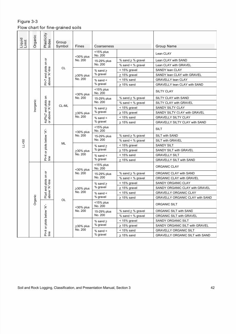
8/9/2019 Caltrans Logging Manual
http://slidepdf.com/reader/full/caltrans-logging-manual 50/93
Figure 3-3
Flow chart for fine-grained soils
L i q u i d
L i m i t
O r g a n i c
P l a s t i c i t y
I n d e x
GroupSymbol Fines Coarseness Group Name
L L < 5 0
I n o r g a n i c
P I > 7 a n d p l o t s o n o r
a b o v e “ A ” - l i n e CL
<30% plusNo. 200
<15% plusNo. 200
Lean CLAY
15-29% plusNo. 200
% sand > % gravel Lean CLAY with SAND
% sand < % gravel Lean CLAY with GRAVEL
>30% plusNo. 200
% sand >% gravel
< 15% gravel SANDY lean CLAY
> 15% gravel SANDY lean CLAY with GRAVEL
% sand <% gravel
< 15% sand GRAVELLY lean CLAY
> 15% sand GRAVELLY lean CLAY with SAND
4 < P I < 7 a n d p l o t s o n
o r a b
o v e “ A ” - l i n e
CL-ML
<30% plusNo. 200
<15% plusNo. 200
SILTY CLAY
15-29% plusNo. 200
% sand > % gravel SILTY CLAY with SAND
% sand < % gravel SILTY CLAY with GRAVEL
>30% plus
No. 200
% sand >% gravel
< 15% gravel SANDY SILTY CLAY
> 15% gravel SANDY SILTY CLAY with GRAVEL
% sand <% gravel
< 15% sand GRAVELLY SILTY CLAY
> 15% sand GRAVELLY SILTY CLAY with SAND
P I < 4 o r p l o t s b e l o w “ A ”
l i n e
ML
<30% plusNo. 200
<15% plusNo. 200
SILT
15-29% plusNo. 200
% sand > % gravel SILT with SAND
% sand < % gravel SILT with GRAVEL
>30% plusNo. 200
% sand >% gravel
< 15% gravel SANDY SILT
> 15% gravel SANDY SILT with GRAVEL
% sand <% gravel
< 15% sand GRAVELLY SILT
> 15% sand GRAVELLY SILT with SAND
O r g a n i c
P I > 4 a n d p l o t s o n
o r
a b o v e “ A ” - l i n e
OL
<30% plusNo. 200
<15% plusNo. 200
ORGANIC CLAY
15-29% plusNo. 200
% sand > % gravel ORGANIC CLAY with SAND
% sand < % gravel ORGANIC CLAY with GRAVEL
>30% plusNo. 200
% sand >% gravel
< 15% gravel SANDY ORGANIC CLAY
> 15% gravel SANDY ORGANIC CLAY with GRAVEL
% sand <% gravel
< 15% sand GRAVELLY ORGANIC CLAY
> 15% sand GRAVELLY ORGANIC CLAY with SAND
P I < 4 o r p l o t s b e l o w “ A ”
l i n
e
<30% plusNo. 200
<15% plusNo. 200
ORGANIC SILT
15-29% plusNo. 200
% sand > % gravel ORGANIC SILT with SAND
% sand < % gravel ORGANIC SILT with GRAVEL
>30% plusNo. 200
% sand >% gravel
< 15% gravel SANDY ORGANIC SILT
> 15% gravel SANDY ORGANIC SILT with GRAVEL
% sand <
% gravel
< 15% sand GRAVELLY ORGANIC SILT
> 15% sand GRAVELLY ORGANIC SILT with SAND
Soil and Rock Logging, Classification, and Presentation Manual, Section 3 42

8/9/2019 Caltrans Logging Manual
http://slidepdf.com/reader/full/caltrans-logging-manual 51/93
Figure 3-3, cont inued
L i q u i d L i m i t
O r g a n i c
P l a s t i c i t y
I n d e x
GroupSymbol Fines Coarseness Group Name
L L > 5 0
I n o r g a n i c
P l o t s o n o r a b o v e “ A ” - l i n e
CH
<30% plusNo. 200
<15% plus
No. 200
Fat CLAY
15-29% plusNo. 200
% sand > % gravel Fat CLAY with SAND
% sand < % gravel Fat CLAY with GRAVEL
>30% plusNo. 200
% sand > %gravel
< 15% gravel SANDY fat CLAY
> 15% gravel SANDY fat CLAY with GRAVEL
% sand < %gravel
< 15% sand GRAVELLY fat CLAY
> 15% sand GRAVELLY fat CLAY with SAND
P l o t s b e
l o w “ A ” - l i n e
MH
<30% plusNo. 200
<15% plusNo. 200
Elastic SILT
15-29% plusNo. 200
% sand > % gravel Elastic SILT with SAND
% sand < % gravel Elastic SILT with GRAVEL
>30% plusNo. 200
% sand > %gravel
< 15% gravel SANDY elastic SILT
> 15% gravel SANDY elastic SILT with GRAVEL% sand < %gravel
< 15% sand GRAVELLY elastic SILT
> 15% sand GRAVELLY elastic SILT with SAND
O r g a n i c
P l o t s o n o r a b o v e “ A ” - l i n e
OH
<30% plusNo. 200
<15% plusNo. 200
ORGANIC CLAY
15-29% plusNo. 200
% sand > % gravel ORGANIC CLAY with SAND
% sand < % gravel ORGANIC CLAY with GRAVEL
>30% plusNo. 200
% sand > %gravel
< 15% gravel SANDY ORGANIC CLAY
> 15% gravel SANDY ORGANIC CLAY with GRAVEL
% sand < %gravel
< 15% sand GRAVELLY ORGANIC CLAY
> 15% sand GRAVELLY ORGANIC CLAY with SAND
P l o t s b e l o w “ A ” - l i n e
<30% plusNo. 200
<15% plusNo. 200
ORGANIC SILT
15-29% plusNo. 200
% sand > % gravel ORGANIC SILT with SAND
% sand < % gravel ORGANIC SILT with GRAVEL
>30% plusNo. 200
% sand > %gravel
< 15% gravel SANDY ORGANIC SILT
> 15% gravel SANDY ORGANIC SILT with GRAVEL
% sand < %gravel
< 15% sand GRAVELLY ORGANIC SILT
> 15% sand GRAVELLY ORGANIC SILT with SAND
Soil and Rock Logging, Classification, and Presentation Manual, Section 3 43

8/9/2019 Caltrans Logging Manual
http://slidepdf.com/reader/full/caltrans-logging-manual 52/93
3.2.2.2 Procedure for Classif ication ofCoarse-Grained Soils
If 50% or more by dry weight of the test specimen
is retained on the No. 200 sieve the soil is coarsegrained. Coarse-grained soils are classified using
the following procedure:
•
Classify the soil as gravel if more than 50% ofthe coarse fraction (plus No. 200 sieve) is
retained on the No. 4 sieve.
• Classify the soil as sand if 50% or more of thecoarse fraction (plus No. 200 sieve) passes
through the No. 4 sieve.
• If 12% or less of the test specimen passesthrough the No. 200 sieve, plot the cumulative
particle-size distribution and compute the
coefficient of uniformity, Cu, and coefficient ofcurvature, Cc, as given in Equations 1
and 2.
Equation 1 D60Cu =
D10
Equation 2 ( )2 D
Cc =
30
( D10 × D60 )
Where D10, D30, and D60 are the particle-size
diameters corresponding to 10, 30, and 60 percentiles passing on the cumulative particle
size distribution curve. It may be necessary toextrapolate the curve to obtain the D10 diameter.
Use the above results to determine the
classification according to Figure 3-4 on thefollowing page.
Soil and Rock Logging, Classification, and Presentation Manual, Section 3 44

8/9/2019 Caltrans Logging Manual
http://slidepdf.com/reader/full/caltrans-logging-manual 53/93
Figure 3-4
Flow chart for coarse-grained soil s
Fines Grade Type of FinesGroupSymbol
Sand/ Gravel Group Name
G r a v e l
< 5%
Cu>41<Cc<3
GW< 15% sand Well-graded GRAVEL
> 15% sand Well-graded GRAVEL with SAND
Cu<41>Cc>3
GP< 15% sand Poorly graded GRAVEL
> 15% sand Poorly graded GRAVEL with SAND
5-12%
Cu>41<Cc<3
ML or MH GW-GM< 15% sand Well-graded GRAVEL with SILT
> 15% sand Well-graded GRAVEL with SILT and SAND
CL, CH or CL-ML GW-GC
< 15% sandWell-graded GRAVEL with CLAY (or SILTYCLAY)
> 15% sandWell-graded GRAVEL with CLAY and SAND (orSILTY CLAY and SAND)
Cu<4
1>Cc>3
ML or MH GP-GM< 15% sand Poorly graded GRAVEL with SILT
> 15% sand Poorly graded GRAVEL with SILT and SAND
CL, CH or CL-ML GP-GC< 15% sand
Poorly graded GRAVEL with CLAY (or SILTY
CLAY)
> 15% sandPoorly graded GRAVEL with CLAY and SAND(or SILTY CLAY and SAND)
> 12%
ML or MH GM< 15% sand SILTY GRAVEL
> 15% sand SILTY GRAVEL with SAND
CL or CH GC< 15% sand CLAYEY GRAVEL
> 15% sand CLAYEY GRAVEL with SAND
CL-ML GC-GM< 15% sand SILTY, CLAYEY GRAVEL
> 15% sand SILTY, CLAYEY GRAVEL with SAND
S a n d
< 5%
Cu>61<Cc<3
SW< 15% gravel Well-graded SAND
> 15% gravel Well-graded SAND with GRAVEL
Cu<61>Cc>3
SP< 15% gravel Poorly graded SAND
> 15% gravel Poorly graded SAND with GRAVEL
5-12%
Cu>61<Cc<3
ML or MH SW-SM< 15% gravel Well-graded SAND with SILT
> 15% gravel Well-graded SAND with SILT and GRAVEL
CL, CH or CL-ML SW-SC< 15% gravel Well-graded SAND with CLAY
> 15% gravel Well-graded SAND with CLAY and GRAVEL
Cu<61>Cc>3
ML or MH SP-SM< 15% gravel Poorly graded SAND with SILT
> 15% gravel Poorly graded SAND with SILT and GRAVEL
CL, CH or CL-ML SP-SC< 15% gravel Poorly graded SAND with CLAY
> 15% gravel Poorly graded SAND with CLAY and GRAVEL
> 12%
ML or MH SM< 15% gravel SILTY SAND
> 15% gravel SILTY SAND with GRAVEL
CL or CH SC< 15% gravel CLAYEY SAND
> 15% gravel CLAYEY SAND with GRAVEL
CL-ML SC-SM< 15% gravel SILTY, CLAYEY SAND
> 15% gravel SILTY, CLAYEY SAND with GRAVEL
Soil and Rock Logging, Classification, and Presentation Manual, Section 3 45

8/9/2019 Caltrans Logging Manual
http://slidepdf.com/reader/full/caltrans-logging-manual 54/93

8/9/2019 Caltrans Logging Manual
http://slidepdf.com/reader/full/caltrans-logging-manual 55/93
3.3 Revising Rock Identif ication and Description for Borehole Cores UsingLaboratory Test Results
One additional component, relative strength of intact rock, can be added to the descriptive sequence for rock.
Figure 3-9
Rock Identification and Descriptive Sequence
S e q u e n c e
Identification Components
Refer to Section
R e q u i r e d
O p t i o n a l
F i e l d
L a b
1 Rock Name 2.5.2 J
Description Components
2 Rock Grain-size 2.5.3 EE
3 Bedding Spacing 2.5.4 J
4 Color 2.5.5 J
5 Texture 2.5.6 EE
6 Weathering Descriptors for Intact Rock 2.5.7 J
7 Relative Strength of Intact Rock 3.3.1 J
8 Rock Hardness 2.5.8 J
9 Fracture Density 2.5.9 J
10 Discontinuity Type 2.5.10 EE
11 Discontinuity Condition (Weathering, Infilling and Healing) 2.5.11 EE
12 Discontinuity Dip Magnitude 2.5.12 EE
13 Rate of Slaking (Jar Slake Test) 2.5.13 EE
14 Odor 2.5.14 EE
15 Additional Comments 2.5.15 EE
3.3.1 Strength of Intact Rock
Absent discontinuities, the strength of intact rock is best determined using unconfined compressionlaboratory testing.
Figure 3-10
Descriptors for Relative Strength of Intact Rock
Description Uniaxial Compressive Strength (psi)Extremely Strong > 30,000
Very Strong 14,500 – 30,000
Strong 7,000 – 14,500
Medium Strong 3,500 – 7,000
Weak 700 – 3,500
Very Weak 150 – 700
Extremely Weak < 150
Soil and Rock Logging, Classification, and Presentation Manual, Section 3 47

8/9/2019 Caltrans Logging Manual
http://slidepdf.com/reader/full/caltrans-logging-manual 56/93
(This page left intentionally blank)
Soil and Rock Logging, Classification, and Presentation Manual, Section 3 48

8/9/2019 Caltrans Logging Manual
http://slidepdf.com/reader/full/caltrans-logging-manual 57/93
Section 4:Methods of Presentation of Subsurface Information
4.1 Introduction
The process of creating boring logs, i.e., Log of
Test Borings (LOTB) and Boring Records (BR)can be summarized in four steps:
• Field sampling and descriptions (Section 2)
• Quality check of field descriptions (Section 2)
• Refinement of descriptions, and classification
of soil, based on laboratory test results, if performed (Section 3)
• Preparation of the boring logs (Sections 4
and 5)
This section provides details and guidance forincorporating laboratory test data and preparing
boring logs. Figure 4-1 is a schematicrepresentation of the process from obtaining
subsurface information to the creation of boringlogs.
4.2 Factual vs. InterpretiveSubsurface Data
FHWA guidelines state: “factual subsurface data
which is pertinent to the project subsurfaceconditions should be presented in an easily
understood fashion on the contract documents.”However, there is an inherent level of professional
interpretation in describing subsurface conditionsthat cannot be avoided.
Some examples:
• Field description and identification procedures,
according to ASTM D 2488-06, requireestimation and interpretation.
•
Sampling may occur at discrete intervals, yetlayer boundaries may fall between sampling
locations. The boundaries may be identified based on visual observations of cuttings during
boring advancement. There may be uncertaintyas to the depth at which a material change
occurs.
• Continuity of material types between discretesampling locations is sometimes difficult to
confirm.
Figure 4-1
FieldSamplingandDescriptions(Sec. 2)
QualityCheck ofFieldObservations(Sec. 2)
YES NO
LaboratoryTests?
IncorporateLaboratory Data,RefineDescriptions, andClassify (Sec. 3)
PrepareBoring Logs
(Sec. 4 & 5)
Soil and Rock Logging, Classification, and Presentation Manual, Section 4 49

8/9/2019 Caltrans Logging Manual
http://slidepdf.com/reader/full/caltrans-logging-manual 58/93
4.3 Incorporating Laboratory Data, the boring log presentation format and provide
clarity, especially to prospective bidders.Refining Descriptions, andClassifying Soil
When describing soil or rock, the geoprofessional 4.3.2 General Rules and Considerations
shall use the most reliable data available. Such data
could be field-generated, or a combination of field-
and laboratory-generated data. If laboratory testsare performed, and in the opinion of the
geoprofessional, those test results represent theactual conditions of the soil or rock, those test
results shall control the identification, description,or classification.
Laboratory tests are usually not performed on
every sample, especially on contiguous samples
within a layer of similar material. Professional judgment should be used to apply test results from
one sample to the descriptor of contiguous sampleswithin a boring when the field observations were
such that the geoprofessional considers that
particular attribute of the material to be consistentacross the contiguous samples.
For example, three contiguous samples were
determined to be “medium stiff” using the thumbmethod. However, a triaxial test on one of those
samples indicated that the material was in fact“stiff.” In this example, the consistency descriptor
for the entire layer should be “stiff.”
4.3.1 Subsur face Data PresentationMethod
A “layer presentation” method shall be used to
present soil and rock descriptions on boring logs.(See Figure 4-3.) This method presents a single primary description for a layer spanning one or
more contiguous sample locations. However, thelayer description may vary with depth as
observations and/or laboratory testing at sample
locations warrant. This method is used to simplify
The following general rules apply to the layer
presentation method:
• A change in a soil’s Group Symbol or a rocktype shall result in a new layer within the
boring log.
• Reliable laboratory test results shall be usedwhen performed to determine the applicable
descriptors within the descriptive sequence (i.e.
Group Name and Symbol, consistency,gradation properties, plasticity, and rock
strength).
• Individual descriptors for contiguous samples
with the same descriptions and classificationsshould be adjusted based on the test results of
one or more representative samples. Use ofmore than one test sample is encouraged.
• When specifying a descriptive range, the range
shall not span more than one step on the range
of descriptors. For example, “stiff to very stiff”would be acceptable; but “soft to hard” would
not be acceptable because the range is too broad to be useful.
Exception: Any range of colors is acceptable.
• The descriptive sequence used to describe alayer of soil or rock shall describe that layer inits entirety. Where changes are noted at depths
within the layer, those changes shall replace the preceding descriptor and shall apply from that
depth to the bottom of the layer.
• The layer presentation of the boring log shallenable the reader to derive individual sample
descriptions based on the layer description andsample information provided.
Soil and Rock Logging, Classification, and Presentation Manual, Section 4 50

8/9/2019 Caltrans Logging Manual
http://slidepdf.com/reader/full/caltrans-logging-manual 59/93

8/9/2019 Caltrans Logging Manual
http://slidepdf.com/reader/full/caltrans-logging-manual 60/93

8/9/2019 Caltrans Logging Manual
http://slidepdf.com/reader/full/caltrans-logging-manual 61/93
Section 5:Boring Log and Legend Presentation Formats
5.1 Introduction
The Department uses the following formats to present subsurface information:
•
Log of Test Boring (LOTB), and/or• Boring Record (BR).
An LOTB is typically associated with a structure facility and is attached to Project Plans. A BR is typicallyassociated with an earthwork facility and is attached to a Geotechnical Report. If a subsurface exploration
was performed, there shall be at least one type of log presentation.
5.2 Log of Test Boring
Figure 5-1
Example of LOTB
Soil and Rock Logging, Classification, and Presentation Manual, Section 5 53
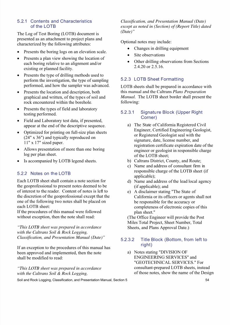
8/9/2019 Caltrans Logging Manual
http://slidepdf.com/reader/full/caltrans-logging-manual 62/93
5.2.1 Contents and Characterist ics Classification, and Presentation Manual (Date)
of the LOTB except as noted in (Section) of (Report Title) dated
(Date)”The Log of Test Boring (LOTB) document is
presented as an attachment to project plans andcharacterized by the following attributes:
• Presents the boring logs on an elevation scale.
•
Presents a plan view showing the location ofeach boring relative to an alignment and/or
existing or planned facility.
• Presents the type of drilling methods used to
perform the investigation, the type of sampling performed, and how the sampler was advanced.
• Presents the location and description, both
graphical and written, of the types of soil androck encountered within the borehole.
• Presents the types of field and laboratory
testing performed.• Field and Laboratory test data, if presented,
appear at the end of the descriptive sequence.
• Optimized for printing on full-size plan sheets
(24" x 36") and typically reproduced on11" x 17" sized paper.
• Allows presentation of more than one boring
log per plan sheet.
• Is accompanied by LOTB legend sheets.
5.2.2 Notes on the LOTB
Each LOTB sheet shall contain a note section for
the geoprofessional to present notes deemed to be
of interest to the reader. Content of notes is left tothe discretion of the geoprofessional except that the
one of the following two notes shall be placed oneach LOTB sheet:
If the procedures of this manual were followed
without exception, then the note shall read:
“This LOTB sheet was prepared in accordancewith the Caltrans Soil & Rock Logging,
Classification, and Presentation Manual (Date)”
If an exception to the procedures of this manual has
been approved and implemented, then the noteshall be modified to read:
“This LOTB sheet was prepared in accordance
with the Caltrans Soil & Rock Logging,
Optional notes may include:
• Changes in drilling equipment
•
Site observations• Other drilling observations from Sections
2.4.20 or 2.5.16.
5.2.3 LOTB Sheet Formatt ing
LOTB sheets shall be prepared in accordance with
this manual and the Caltrans Plans Preparation
Manual. The LOTB sheet border shall present the
following:
5.2.3.1 Signature Block (Upper RightCorner)
a) The State of California Registered CivilEngineer, Certified Engineering Geologist,
or Registered Geologist seal with thesignature, date, license number, and
registration certificate expiration date of the
engineer or geologist in responsible chargeof the LOTB sheet;
b) Caltrans District, County, and Route;c) Name and address of consultant firm in
responsible charge of the LOTB sheet (ifapplicable);
d) Name and address of the lead local agency
(if applicable); ande) A disclaimer stating "The State of
California or its officers or agents shall not
be responsible for the accuracy orcompleteness of electronic copies of this
plan sheet."(The Office Engineer will provide the Post
Miles Total Project, Sheet Number, Total
Sheets, and Plans Approval Date.)
5.2.3.2 Title Block (Bottom, from left toright)
a) Notes stating "DIVISION OF
ENGINEERING SERVICES" and
"GEOTECHNICAL SERVICES." For
consultant-prepared LOTB sheets, insteadof those notes, show the name of the Design
Soil and Rock Logging, Classification, and Presentation Manual, Section 5 54

8/9/2019 Caltrans Logging Manual
http://slidepdf.com/reader/full/caltrans-logging-manual 63/93
Oversight (i.e., OSFP/OSCM Senior
Liaison) Engineer and sign-off date. b) “FUNCTIONAL SUPERVISOR”: The
name of the person in charge of the
functional unit responsible for providing
oversight of the registered engineer orgeologist who developed the LOTB sheet.
c)
“DRAWN BY”: The name of the personwho prepared (drafted) the LOTB sheet
d) “CHECKED BY”: The name of the person
who performed the quality control check ofthe LOTB sheet
e) “FIELD INVESTIGATION BY”: Thename(s) of the field investigator(s);
f) A note stating "STATE OF CALIFORNIA,
DEPARTMENT OFTRANSPORTATION" with a scale below
the sub-block and a label on the left side
stating "ORIGINAL SCALE IN INCHESFOR REDUCED PLANS." For consultant
prepared LOTB sheets, the note shall state"PREPARED FOR THE STATE OF
CALIFORNIA, DEPARTMENT OFTRANSPORTATION."
g) A note stating "DIVISION OF
ENGINEERING SERVICESSTRUCTURE DESIGN." For consultant
prepared LOTB sheets, instead of this note,show the name of the Project Engineer;
h)
The Caltrans Contract ExpenditureAuthorization (CU and EA) numbers;
i) The State-assigned Bridge (or Structure)
Number, Kilometer Post, and the Stateassigned Bridge (or Structure) Name;
j) The initial drawn by and subsequent
revision dates; andk) A label stating "LOG OF TEST BORINGS
_ OF _" (if applicable).(The Office Engineer will provide the Sheet
Number and Total Sheets Number.)
5.2.3.3 Plan View
a) Plan View shall be shown at the top of thefirst LOTB sheet. When the site is
sufficiently large or complex, the firstLOTB sheet should be used entirely for the
Plan View.
b) When multiple LOTB sheets are drafted,they shall be numbered with reference to
the stationing of the control line (i.e.,
showing sheet No. 1 with the loweststationing and the last sheet with the highest
stationing).
c) A distinct Plan View of the project site that
is independent of the Profile View shall beshown on the LOTB.
d) Show the location, description, andelevation of the benchmark used for
determining the top of boring elevations at
the top left side of the Plan View under theheading “BENCHMARK”. Identify the
vertical datum (National Geodetic VerticalDatum, U.S. Geological Survey, U.S. Coast
& Geodetic Survey, District, etc.) used to
determine the benchmark elevations.e) Show the scale directly below the Plan
View label.
f)
Show a North arrow.g) Lines or control lines shown in the Plan
View shall be consistent with those shownon the General Plan sheet.
h) Show stationing and names for control lines.Stationing shall increase from left to right.
Show a minimum of two stations on all
lines.i) Show control line intersection stationing
and bearings. j) Show names and directions of nearest cities.
k)
Show names and directions of stream flowswhen applicable.
l) Plot boring locations with symbols as
shown in the legend to identify drillingmethods (e.g., auger hole, rotary hole, cone
penetration). The Hole Identification shall
be presented with each symbol.m) Boring locations are to be identified by
reference line, station, and offset.Coordinates, such as Northing and Easting,
may also be shown on the LOTB sheets.
5.2.3.4 Prof ile View
a) Show the control line, increasing from left
to right, horizontally across the bottom ofthe Profile View.
b) Show the elevations and grid lines on both
the left and right margins. Numericalvalues shall be in multiples of 10 (i.e. 20,
10, 0, -10, -20).
Soil and Rock Logging, Classification, and Presentation Manual, Section 5 55

8/9/2019 Caltrans Logging Manual
http://slidepdf.com/reader/full/caltrans-logging-manual 64/93
c) Show the Hole Identification, top of hole
elevation, stationing, and offset at the top ofeach boring log.
d) Show types and diameters of each boring as
shown in the legend.
e) Show the completion date of boring (m/d/y)at the bottom of each boring log.
f)
Show “Terminated at EL. XX’” to indicatethe bottom of boring elevation.
g) Show the SPT hammer energy ratio,
“Hammer Energy Ratio (ER i) = XX%,” atthe bottom of each boring.
h) Show date and elevation of groundwatermeasurement.
i) Show results from field penetration tests at
relevant elevations along the boring log. j) Show types of field and laboratory tests
with symbols as indicated in the legend, at
relevant elevations along the right side ofthe boring log.
k) Show the Profile scales (horizontal andvertical) under the heading “PROFILE”.
5.2.3.5 Addit ional information to beincluded
a) Show standard note identifying the logging
practice as follows:
“This LOTB sheet was prepared in
accordance with the Caltrans Soil & Rock Logging, Classification, and Presentation
Manual”
When a LOTB presents information that
deviates from the Caltrans Soil & RockLogging, Classification, and Presentation
Manual standards, the standard note shall be modified to read as follows:
“This LOTB sheet was prepared in
accordance with the Caltrans Soil & Rock Logging, Classification, and Presentation
Manual except as noted in (section) of
(Report Title) dated (Date)”
b) Descriptions of types of samplers used for
the field exploration.
5.2.4 As-Bui lt LOTB Sheet Formatt ing
As-Built LOTB sheet(s) shall be prepared
according to the following standards.
5.2.4.1 Obtaining and Reproducing the As-Buil t LOTB Sheet
a) Reproducible copies of As-Built LOTBsheets may be obtained from the Microfilm
Services Units in the Caltrans District
Offices. If the As-Built LOTB sheets provided to Local Agencies or consultants
by the Caltrans District Offices are notlegible, a full sized copy should be
requested from Geotechnical Services.
b) As-Built LOTB sheets shall be size "D"(24" by 36"). The As-Built LOTB title
block shall be sized to fit and placed over
any open space (preferably toward the top)on the As-Built LOTB sheet.
c) Information on the As-Built LOTB sheetshall be clear and legible. In order to
improve the legibility of the information, itmay be necessary to darken the line work
and the notations.
5.2.4.2 Typical Modifications to As-BuiltLOTB Sheets
a) If As-Built LOTB sheets are shown in
metric units, the offset and stationinglocation of each boring must be converted
to imperial units. A table shall be addedshowing the dual dimensions (Metric and
English) of each boring. The table shall
show the station and offset in relation to thenew English line. The General Plan will
show the current English control line.
5.2.4.3 The As-Built LOTB Title Blockshall include the followinginformation for the currentproject
a) A note stating "GEOTECHNICAL
SERVICES -- DIVISION OF
ENGINEERING SERVICES" (ifapplicable).
b) Caltrans District, County, Route, Post Miles
- Total Project, State-assigned Bridge (or
Structure) Number and Name, and
Expenditure Authorization (CU and EA)
Soil and Rock Logging, Classification, and Presentation Manual, Section 5 56

8/9/2019 Caltrans Logging Manual
http://slidepdf.com/reader/full/caltrans-logging-manual 65/93
numbers. The Office Engineer will provide
the Sheet Number and Total Sheets Number.c) The State of California Registered Civil
Engineer or Registered Geologist seal with
the signature, date, license number, and
registration certificate expiration date of theengineer or geologist in responsible charge
of the LOTB sheet.d) A note stating, "As-Built Log of Test
Borings sheet is considered an
informational document only. As such, theState of California registration seal with
signature, license number and registrationcertificate expiration date confirm that this
is a true and accurate copy of the original
document. It does not attest to the accuracyor validity of the information contained in
the original document. This drawing is
available and presented only for theconvenience of any bidder, contractor or
other interested party."
e) A sub-box stating "LOG OF TEST
BORINGS _ OF _" (if applicable).e) A note stating "A COPY OF THIS LOG
OF TEST BORINGS IS AVAILABLE AT
OFFICE OF STRUCTURE
MAINTENANCE ANDINVESTIGATIONS, SACRAMENTO,
CALIFORNIA" (if applicable).
5.2.5 The LOTB Legend Sheets
The soil and rock legend sheets are standard forms
that provide convenient references for the required
soil and rock description, identification, and/or
classification components presented in this Manual.References for optional descriptors do not appear
on the legend sheets; however, they are explained
in this Manual. To correctly interpret the LOTB,
the reader shall be familiar with this Manual.There are two legend sheets, one predominantly for
soil and the other for rock, as shown in the Figures5-2 and 5-3.
The legend sheets define the format for the
graphical presentation of a boring log and
differentiate among the various borehole andsounding types. The legend sheets also present the
symbols used to identify laboratory tests.
GEOTECHNICAL SERVICES – DIVISION OF ENGINEERING SERVICES
As-Built Log of Test Borings sheet is considered an informational document only. As such, the State of
California registration seal with signature, license number and registration certificate expiration dateconfirm that is this a true and accurate copy of the original document. It does not attest to the accuracy orvalidity of the information contained in the original document. This drawing is available and presented onlyfor the convenience of any bidder, contractor or other interested party.DIST. COUNTY ROUTE POST MILES – TOTAL PROJECT SHEET NO. TOTAL SHEETS
08 SBD 210 10.00-15.00 24 25
REGISTERED ENGINEER – CIVIL DATE
MAIN STREET OVERCROSSING
LOG OF TEST BORINGS 5 OF 6 NOTE: A COPY OF THIS LOG OF TEST BORINGS IS AVAILABLE ATOFFICE OF STRUCTURE MAINTENANCE AND INVESTIGATIONS,SACRAMENTO, CALIFORNIA
CU: 12EA: 432563
BRIDGE NO.12-3456
Soil and Rock Logging, Classification, and Presentation Manual, Section 5 57

8/9/2019 Caltrans Logging Manual
http://slidepdf.com/reader/full/caltrans-logging-manual 66/93
(This page left intentionally blank)
Soil and Rock Logging, Classification, and Presentation Manual, Section 5 58

8/9/2019 Caltrans Logging Manual
http://slidepdf.com/reader/full/caltrans-logging-manual 67/93

8/9/2019 Caltrans Logging Manual
http://slidepdf.com/reader/full/caltrans-logging-manual 68/93

8/9/2019 Caltrans Logging Manual
http://slidepdf.com/reader/full/caltrans-logging-manual 69/93
Four general hole-type formats are graphically
presented as follows:
5.2.5.1 Hand Boring
Hand Driven (HD) (1-inch soil tube) and HandAuger (HA) borings shall be presented using the
following format:
Figure 5-4
5.2.5.2 Rotary Bor ing
Rotary Drilled Boring or Diamond Core (R),
Rotary Percussion Boring (Air) (P), Auger Boring(A), shall be presented using the following format:
Figure 5-5
Notes:
If laboratory tests are not shown as being performed, the soil
descriptions presented in the LOTB are based solely on the
visual practices described in this Manual.
Changes in material with depth shall be notedusing the following terms:
Figure 5-6
Definitions for changes in material
Term Definition
Material Change Change in material isobserved in the sampleor core, and the locationof change can be
accurately measured.
Estimated MaterialChange
Change in materialcannot be accuratelylocated because eitherthe change isgradational or becauseof limitations in thedrilling/samplingmethods used.
Soil/Rock Boundary Material changes fromsoil characteristics torock characteristics and
that change can bemeasured or estimated.
5.2.5.3 Dynamic Cone PenetrationSounding
The Dynamic Cone Penetration Sounding (D) shall be presented using the following format:
Figure 5-7
Soil and Rock Logging, Classification, and Presentation Manual, Section 5 61

8/9/2019 Caltrans Logging Manual
http://slidepdf.com/reader/full/caltrans-logging-manual 70/93
5.2.5.4 Cone Penetration Test (CPT) 5.2.5.5 Rock CoringSounding
Rock coring logs shall be presented using the
A Cone Penetration Test (CPT) sounding shall be following format:
presented using the following format: Figure 5-9
Figure 5-8
5.2.5.6 Hole Type Symbols
Hole type is identified within the holeidentification numbering convention (see Section
2.3) and symbolized on the LOTB as follows:
Figure 5-10
Soil and Rock Logging, Classification, and Presentation Manual, Section 5 62

8/9/2019 Caltrans Logging Manual
http://slidepdf.com/reader/full/caltrans-logging-manual 71/93
5.2.5.7 Graphical Representation of Material Types
Soil Group Name and Group Symbol and Rock Type are symbolized on the LOTB as follows:
Figure 5-11
Soil and Rock Logging, Classification, and Presentation Manual, Section 5 63

8/9/2019 Caltrans Logging Manual
http://slidepdf.com/reader/full/caltrans-logging-manual 72/93
5.3 Boring Records
Figure 5-12
Soil and Rock Logging, Classification, and Presentation Manual, Section 5 64
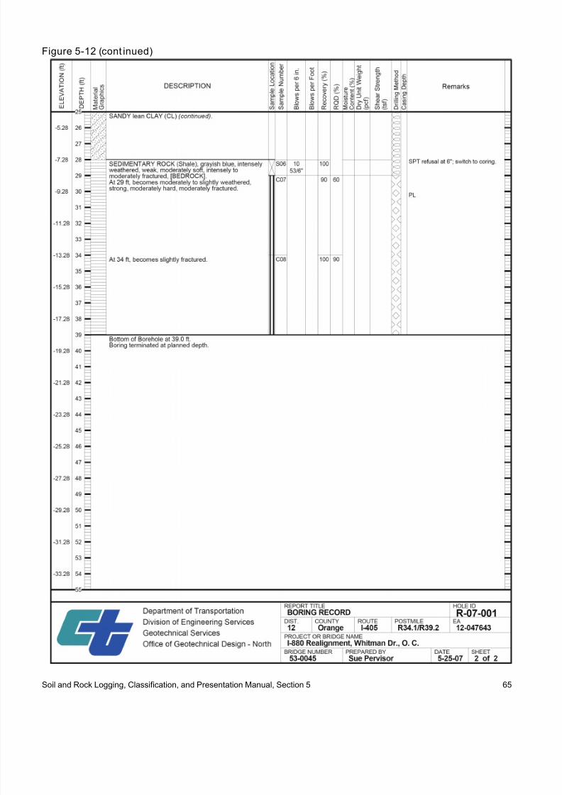
8/9/2019 Caltrans Logging Manual
http://slidepdf.com/reader/full/caltrans-logging-manual 73/93
Figure 5-12 (cont inued)
Soil and Rock Logging, Classification, and Presentation Manual, Section 5 65

8/9/2019 Caltrans Logging Manual
http://slidepdf.com/reader/full/caltrans-logging-manual 74/93
Figure 5-13
Soil and Rock Logging, Classification, and Presentation Manual, Section 5 66

8/9/2019 Caltrans Logging Manual
http://slidepdf.com/reader/full/caltrans-logging-manual 75/93
5.3.1 Content and Characterist ics of theBR
A Boring Record (BR) document is presented as anattachment to a geotechnical report and is
characterized by the following attributes:
•
Presents a single borehole record or CPTsounding.
• Presents the borings to an elevation scale.
• Presents the type of drilling method used to
perform the investigation, the type of sampling performed, and how the sampler was advanced.
• Presents the location and description, both
graphical and written, of the types of soil androck encountered within the borehole.
• Accommodates the presentation of select field
and laboratory test results.• Optimized for printing on 8.5" x 11" sheets
• Is accompanied by BR Legend Sheets.
5.3.2 Notes on the BR
If the procedures of this manual were followed
without exception, then the following note shallappear on the first page of the BR:
“This Boring Record was prepared in accordance
with the Caltrans Soil & Rock Logging,
Classification, and Presentation Manual (Date)”
If an exception to the procedures of this manual has
been approved and implemented, then the note
shall be modified to read:
“This Boring Record was prepared in accordance
with the Caltrans Soil & Rock Logging,
Classification, and Presentation Manual (Date)
except as noted in (Section) of (Report Title) dated
(Date)”
Optional notes are left to the discretion of thegeoprofessional and, if are specific to an elevation
or depth, should be presented at the appropriatelocation in the “Remarks” column. These notes
may include:
• Changes in drilling equipment
• Other drilling observations from Sections2.4.22 or 2.5.17.
Notes that are more general in content, such as asite observation, should be placed within the body
of the geotechnical report.
5.3.3 The Boring Record Legend Sheets
The soil and rock legend sheets are standard forms
that provide convenient references for the required
soil and rock description, identification, and/orclassification components presented in this Manual.References for optional descriptors do not appear
on the legend sheets; however, they are explained
in this Manual. To correctly interpret the BR, the
reader shall be familiar with this Manual.
There are three legend sheets: one predominantlyfor soil and the other for rock, as shown in thefollowing figures.
The legend sheets define the format for the
graphical presentation of a boring log and
differentiate among the various borehole andsounding types. The legend sheets also present the
symbols used to identify laboratory tests.
Soil and Rock Logging, Classification, and Presentation Manual, Section 5 67

8/9/2019 Caltrans Logging Manual
http://slidepdf.com/reader/full/caltrans-logging-manual 76/93

8/9/2019 Caltrans Logging Manual
http://slidepdf.com/reader/full/caltrans-logging-manual 77/93
Figure 5-15
Soil and Rock Logging, Classification, and Presentation Manual, Section 5 69

8/9/2019 Caltrans Logging Manual
http://slidepdf.com/reader/full/caltrans-logging-manual 78/93
Figure 5-16
Soil and Rock Logging, Classification, and Presentation Manual, Section 5 70

8/9/2019 Caltrans Logging Manual
http://slidepdf.com/reader/full/caltrans-logging-manual 79/93
References
Association of State Highway and Transportation Officials (AASHTO) (1988), Manual on Subsurface
Investigations. Washington, D.C.
American Society for Testing and Materials (ASTM), Annual Book of ASTM Standards, 2007 Edition,ASTM International, West Conshohocken, PA
Das, Braja M. (1997), Advanced Soil Mechanics,2nd Edition, Taylor & Francis Group
Departments of the Army And The Air Force (1983), Backfill For Subsurface Structures, 5-8184/AFM 85,
Chap. 5, Technical Manual Headquarters, No. 5-818-4, Air Force Manual No. 88-5, Chapter 5Washington, Dc, 1 June 1983
International Society of Rock Mechanics (ISRM) (1981), Suggested Methods for the Quantitative
Description of Discontinuities in Rock Masses, ed. E. T. Brown
U.S. Department of the Interior, Bureau of Reclamation (2001), Engineering Geology Field Manual,
2nd
Edition
U.S. Department of Transportation, Federal Highway Administration, Geotechnical Guideline No.15,
Differing Site Conditions, Geotechnical Engineering Notebook (1996)
Wyllie, D.C., Mah, C. M. (2004), Rock Slope Engineering: Civil and Mining, 4th
Edition, Taylor & Francis
Zumberge, J. H., Rutford, R. H., Carter, J. L. (2003), Laboratory Manual For Physical Geology,
11th
Edition
Soil and Rock Logging, Classification, Description, and Presentation Manual, References 71

8/9/2019 Caltrans Logging Manual
http://slidepdf.com/reader/full/caltrans-logging-manual 80/93
(This page left intentionally blank)
Soil and Rock Logging, Classification, Description, and Presentation Manual, References 72

8/9/2019 Caltrans Logging Manual
http://slidepdf.com/reader/full/caltrans-logging-manual 81/93
Appendix A:Field Test Procedures
A.1 Pocket Penetrometer
The Pocket Penetrometer test is conducted using
the following general instructions:• To begin test, remove protective cap, push ring
against body so that low side reads 0.
• Slowly insert piston until engraved mark islevel with soil.
• Observe the reading in TSF (KG/SQ CM) usinglow side of ring, (side closest to the piston end):
record reading and repeat.
• For weak soils, use 1” adapter foot, multiply
reading by 0.0625.
A.2 Torvane
The Torvane test is conducted using the followinggeneral instructions:
• To start test, push indicator counter clockwiseto zero stop.
• Select reasonably flat surface at least 1 inch indiameter.
• Using midsize vane, one revolution equals 1TSF (1KG/SQ CM).
• One revolution using small and large vane
equals respectively 2.5 and 0.2 TSF (KG/SQCM).
• Press pocket vane shear tester into soil to depthof blade; maintain constant vertical pressure
while turning knob clockwise at rate to developfailure within 5 to 10 seconds.
•
After failure develops, release remaining springtension slowly. Pointer will indicate maximum
shear value until manually reset.
A.3 Dry Strength
From the specimen, select enough material to mold
into a ball about 1 in. (25 mm) in diameter. Mold
the material until it has the consistency of putty,adding water if necessary. From the molded
material, make at least three test specimens. A test
specimen shall be a ball of material about 1 ⁄ 2 in.(12 mm) in diameter. Allow the test specimens to
dry in air, or sun, or by artificial means, as long asthe temperature does not exceed 60°C. If the test
specimen contains natural dry lumps, those that are
about 1 ⁄ 2 in. (12 mm) in diameter may be used in place of the molded balls. Test the strength of the
dry balls or lumps by crushing between the fingers. Note the strength as none, low, medium, high, or
very high in accordance with the criteria in the
table in Section 2.4.14. If natural dry lumps areused, do not use the results of any of the lumps that
are found to contain particles of coarse sand. The
presence of high-strength water-soluble cementingmaterials, such as calcium carbonate, may cause
exceptionally high dry strengths. The presence ofcalcium carbonate can usually be detected from the
intensity of the reaction with dilute hydrochloric
acid.
A.4 Dilatancy
From the specimen, select enough material to mold
into a ball about 1 ⁄ 2 in. (12 mm) in diameter. Moldthe material, adding water if necessary, until it has
a soft, but not sticky, consistency. Smooth the soil ball in the palm of one hand with the blade of a
knife or small spatula. Shake horizontally, striking
the side of the hand vigorously against the other
hand several times. Note the reaction of waterappearing on the surface of the soil. Squeeze thesample by closing the hand or pinching the soil
between the fingers, and note the reaction as none,
slow, or rapid in accordance with the criteria in the
table in Section 2.4.15. The reaction is the speedwith which water appears while shaking, and
disappears while squeezing.
A.5 Toughness
Following the completion of the dilatancy test, the
test specimen is shaped into an elongated pat androlled by hand on a smooth surface or between the
palms into a thread about 1 ⁄ 8 in. (3 mm) in
Soil and Rock Logging, Classification, Description, and Presentation Manual, Appendix 73

8/9/2019 Caltrans Logging Manual
http://slidepdf.com/reader/full/caltrans-logging-manual 82/93
diameter. (If the sample is too wet to roll easily, it A.7 Calc ium Carbonateshould be spread into a thin layer and allowed to
lose some water by evaporation.) Fold the samplethreads and reroll repeatedly until the thread
crumbles at a diameter of about 1 ⁄ 8 in. The thread
will crumble at a diameter of 1 ⁄ 8 in. when the soilis near the plastic limit. Note the pressure required
to roll the thread near the plastic limit. Also, notethe strength of the thread. After the thread
crumbles, the pieces should be lumped together
and kneaded until the lump crumbles. Note thetoughness of the material during kneading.
Describe the toughness of the thread and lump aslow, medium, or high in accordance with the
criteria in the table in Section 2.4.16.
A.6 Jar Slake Index TestSlaking behavior of intact rock specimens is
quantified as an index. A laboratory index test
called the Slake Durability Test (ASTM D 4644-04)
is the most rigorous method of measuring this behavior. A simple, but less sensitive method can
be employed in the field or in the office to screenspecimens of the Slake Durability test. The “Jar
Slake Test” method is presented here. A water
filled jar and a watch are all that are required to perform this simple test. The steps are as follows:
•
A fragment of rock is immersed in enoughwater to cover it by 15 mm. It is best if the rock
is oven dried. It has been reported that dampmaterial is relatively insensitive to degradation
in this test when compared with dry material.
• After immersion, the fragment is observedcontinuously for the first 10 minutes and
carefully during the first 30 minutes. When a
reaction occurs, it is often during the first 30minutes. A final observation is made after 24
hours.
• The condition of the piece is categorized
(complete breakdown, partial breakdown, nochange), as shown in the table in Section 2.5.14
(Air Force Manual 1983).
Because calcium carbonate is a common cementing
agent, it is important to report its presence, which
is done on the basis of the reaction with dilutehydrochloric acid (HCl). Use the ASTM D 2488
06 standard to describe the reaction with HCl, as
indicated in Figure 2-19 below.
Figure 2-19
Descriptors for calcium carbonate reaction
Description Criteria
None No visible reaction.
Weak Some reaction, with bubbles formingslowly.
Strong Violent reaction, with bubbles formingimmediately.
A.8 Standard Penetration Test
Standard Penetration Tests (SPT) shall beconducted according to the following test methods:
• ASTM D 1586-99, Standard Test Method for
Penetration Test and Split-Barrel Sampling ofSoils
• ASTM D 6066-96, Standard Practice forDetermining the Normalized Penetration
Resistance of Sands for Evaluation ofLiquefaction Potential
The following guidance is provided:
• Blow counts shall be reported on the LOTBand BR as observed in the field, N, with no
corrections.
Where,
N The sum of the hammer blows required
to drive the sampler over the testinterval from 0.5 to 1.5 ft below the
cleanout depth.
• Hammer efficiency shall be noted on the LOTBand BR to allow the reader to determine N60 or
(N1)60.
Where,
ER i Hammer energy ratio
Soil and Rock Logging, Classification, Description, and Presentation Manual, Appendix 74

8/9/2019 Caltrans Logging Manual
http://slidepdf.com/reader/full/caltrans-logging-manual 83/93
N60
Penetration resistance adjusted to a60 % drill rod energy ratio per
ASTM D 6066-96: N60 = Nmeasured X (ER i /60)
(N1)60
Penetration resistance adjusted for
energy and normalized to a 1 ton/ft2
stress level.
• Blow counts for each of the 6 inch incrementsshall be recorded in the field, but not
necessarily reported on the LOTB and BR. The2
nd and 3
rd driving intervals shall be summed
and reported.
For example:
1st 6 in. interval: 10 blows
2nd 6 in. interval: 15 blows
3rd 6 in. interval: 18 blows
N reported as “33”
• For partial increments, the depth of penetrationshall be reported to the nearest 1 inch, inaddition to the number of blows.
For example:
1st 6 in. interval: 20 blows
2nd 6 in. interval: 40 blows
3rd 6 in. interval: 60 blows for 2 inches,
then refusal
N reported as “100/8”
•
If the seating interval (1
st
6 in. interval) is notachieved, note refusal.
For example:
1st 6 in. interval: 50 blows for 2 inches,then refusal
N reported as “REF”
• If a substantial change in material is
encountered over the course of driving thesampler, the 2
nd and 3
rd driving intervals can be
reported separately.
For example:1st 6 in. interval: 10 blows
2nd 6 in. interval: 20 blows
3rd 6 in. interval: 60 blows for 3 inches,
then refusal
N reported as “20/6, 60/3”
A.9 Core Recovery (REC)
The core recovery value (REC), with few
exceptions, provides an indication of the success of
the coring operation in recovering the cored rock.
Portions of the cored rock mass may not berecovered because the fluid used in the drillingoperations transports portions of the rock mass
during the coring operation or the rotation of the
core barrel traps and grinds away portions of therock mass. Diminished core recovery can also be
attributed to voids within the rock mass. Corerecovery is expressed as a percentage.
Σ (Length of the recoveredcore pieces, inches)(100%)
REC =Total length of the core run, inches
A.10 Rock Quality Designation (RQD)
Rock Quality Designation is an index that relates to
the degree of fracturing in a rock mass as observedin a core specimen. A high value of RQD is
indicative of a less fractured rock mass or a rock
mass having widely spaced fractures. RQD is validfor core diameters from 1.4 to 3.35 inches. This
RQD criteria is generally based on ASTM D 6032
02.
Σ (Length of intact core pieces > 4inches)(100%)
RQD =Total length of the core run, inches
Used alone, RQD is not sufficient to provide anadequate description of rock mass quality. The
RQD does not account for joint orientation,tightness, continuity, and gouge material. The RQD
shall be used in combination with other geological
and geotechnical input.
The RQD denotes the percentage of intact rockretrieved from a borehole of any orientation. All
pieces of intact rock core equal to or greater than 4inches long are summed and divided by the total
length of the core run. An intact core is any
segment of core between two open, naturaldiscontinuities.
Soil and Rock Logging, Classification, Description, and Presentation Manual, Appendix 75

8/9/2019 Caltrans Logging Manual
http://slidepdf.com/reader/full/caltrans-logging-manual 84/93
(This page left intentionally blank)
Soil and Rock Logging, Classification, Description, and Presentation Manual, Appendix 76

8/9/2019 Caltrans Logging Manual
http://slidepdf.com/reader/full/caltrans-logging-manual 85/93
Appendix B:Field Logging Aids
B.1 Field Sample Logging Forms
Forms are provided to assist the sample logging
process in the field. One form is used specifically
for soil samples, while the other used for rock
samples.
Soil and Rock Logging, Classification, Description, and Presentation Manual, Appendix 77

8/9/2019 Caltrans Logging Manual
http://slidepdf.com/reader/full/caltrans-logging-manual 86/93
(This page left intentionally blank)
Soil and Rock Logging, Classification, Description, and Presentation Manual, Appendix 78

8/9/2019 Caltrans Logging Manual
http://slidepdf.com/reader/full/caltrans-logging-manual 87/93

8/9/2019 Caltrans Logging Manual
http://slidepdf.com/reader/full/caltrans-logging-manual 88/93
Rock Sample Field Description & Identification
Instructions:
•
Field Description and Identification based upon Soil and Rock Logging, Classification, and Presentation Manual , dated July 1, 2007.
•
Shaded fields are required, non-shaded fields are optional.
•
Intensely weathered or decomposed rock that is friable and that can be reduced to gravel size or smaller by normal hand pressure shall be identified and described as rock followed by the soilidentification or classification, and description in parenthesis.
Project Logged by Date Hole ID
District County Route Postmile EA Sample Depth Sample ID
Drilling or Coring Method Sampler Type and Size
Length of Core Run Length of the recovered core pieces Length of intact core pieces > 4 inches
Recovery (REC) Rock Quality Designation (RQD)
Rock Identification Family NameSedimentaryIgneousMetamorphic
Bedding SpacingMassiveVery thickly beddedThickly beddedModerately beddedThinly beddedVery thinly beddedLaminated
TexturePittedVuggyCavityHoneycombedVesicular
Color Odor
Add it ional Desc rip tion
Rock Grain-Size(Crystalline Igneous and Metamorphic Rock)Very coarse grained or pegmatiticCoarse-grainedMedium-grainedFine-grained Aphanitic
(Sedimentary Rock)Boulder, Boulder ConglomerateCobble, Cobble ConglomeratePebble, Pebble ConglomerateGranule, Granule ConglomerateVery Coarse SandCoarse SandMedium SandFine SandVery Fine SandSilt, Siltstone, ShaleClay, Claystone, Shale
(Pyroclastic Igneous Rock)Block (Angular), Volcanic BrecciaBomb (Rounded), AgglomerateLapilli, Lapilli TuffCoarse Ash, Coarse TuffFine Ash, Fine Tuff
WeatheringFreshSlightly Weathered to FreshSlightly WeatheredModerately to Slightly WeatheredModerately WeatheredIntensely to Moderately Weathered
(Requires completion of Soil SampleField Description and Identificationform)
Intensely WeatheredVery Intensely WeatheredDecomposed
Rock HardnessExtremely HardVery HardHardModerately HardModerately SoftSoftVery Soft
Fracture DensityUnfracturedVery slightly fracturedSlightly to very slightly fracturedSlightly fracturedModerately to slightly fracturedModerately fractured
Intensely to moderately fracturedIntensely fracturedVery intensely to intensely fracturedVery intensely fractured
Discontinuity TypeJoint (JT)Foliation Joint (FJ) or Bedding Joint (BJ)Bedding Plane SeparationIncipient Joint (IJ) or Incipient Fracture (IF)Random Fracture (RF)Mechanical Break (MB)
Fracture Zone (FZ)
Discontinuity Dip Magnitude Jar Slake Index, I j123456
Discontinuity WeatheringFreshSlightly Weathered to FreshSlightly WeatheredModerately to Slightly WeatheredModerately WeatheredIntensely to Moderately WeatheredIntensely WeatheredVery Intensely WeatheredDecomposed
Discontinuity HealingTotally HealedModerately HealedPartially HealedNot Healed
Healing Material:
Discontinuity InfillingRock:
Extremely HardVery HardHardModerately HardModerately SoftSoftVery Soft
Soils:Very SoftSoftMedium StiffStiffVery StiffHard
Soil and Rock Logging, Classification, Description, and Presentation Manual, Appendix 80

8/9/2019 Caltrans Logging Manual
http://slidepdf.com/reader/full/caltrans-logging-manual 89/93
Appendix C:Procedural Documents
Soil and Rock Logging, Classification, Description, and Presentation Manual, Appendix 81

8/9/2019 Caltrans Logging Manual
http://slidepdf.com/reader/full/caltrans-logging-manual 90/93
Soil and Rock Logging, Classification, Description, and Presentation Manual, Appendix 82

8/9/2019 Caltrans Logging Manual
http://slidepdf.com/reader/full/caltrans-logging-manual 91/93
Soil and Rock Logging, Classification, Description, and Presentation Manual, Appendix 83

8/9/2019 Caltrans Logging Manual
http://slidepdf.com/reader/full/caltrans-logging-manual 92/93
Soil and Rock Logging, Classification, Description, and Presentation Manual, Appendix 84

8/9/2019 Caltrans Logging Manual
http://slidepdf.com/reader/full/caltrans-logging-manual 93/93