cambridge technicals in engineering - ocr · inspection and testing 3 3 introduction ... ultrasonic...
TRANSCRIPT

TECHNICALSCambridge
CAMBRIDGE TECHNICALS IN ENGINEERINGLEVEL 3 UNIT 19 – INSPECTION AND TESTING
DELIVERY GUIDEVersion 1

OC
R LEVEL 3 CA
MBRID
GE TEC
HN
ICA
LS IN EN
GIN
EERING
INSPEC
TION
AN
D TESTIN
G
2
CONTENTS
Introduction 3
Related Activities 4
Key Terms 5
Misconceptions 8
Suggested Activities:
Learning Outcome (LO1) 9
Learning Outcome (LO2) 11
Learning Outcome (LO3) 13
Learning Outcome (LO4) 15
Learning Outcome (LO5) 17

OC
R LE
VEL
3 C
AM
BRID
GE
TEC
HN
ICA
LS IN
EN
GIN
EERI
NG
INSP
ECTI
ON
AN
D T
ESTI
NG
3 3
INTRODUCTIONThis Delivery Guide has been developed to provide practitioners with a variety of creative and practical ideas to support the delivery of this qualification. The Guide is a collection of lesson ideas with associated activities, which you may find helpful as you plan your lessons.
OCR has collaborated with current practitioners to ensure that the ideas put forward in this Delivery Guide are practical, realistic and dynamic. The Guide is structured by learning outcome so you can see how each activity helps you cover the requirements of this unit.
We appreciate that practitioners are knowledgeable in relation to what works for them and their learners. Therefore, the resources we have produced should not restrict or impact on practitioners’ creativity to deliver excellent learning opportunities.
Whether you are an experienced practitioner or new to the sector, we hope you find something in this guide which will help you to deliver excellent learning opportunities.
If you have any feedback on this Delivery Guide or suggestions for other resources you would like OCR to develop, please email [email protected].
Unit aimIn ensuring that the business can meet the demands of its customers when manufacturing and supplying goods, suppliers must inspect and test these goods and products prior to completion, to guarantee their levels of quality. Dependent on the product type and process used to manufacture, there are a number of methods which can be used.
The aim of this unit is for learners to develop an understanding of different methods of inspection and testing (including both destructive and non-destructive testing). They will learn how the use of these methods contributes to quality control, and how defects can form in manufacturing components, processes and materials in the first place.
They will also learn about how automatic testing and inspection techniques are used in engineering.
Unit 19 Inspection and Testing
LO1 Understand how inspection and testing methods and processes improve quality control
LO2 Understand how defects can occur in manufacturing materials, processes and components
LO3 Understand how destructive testing methods are used for quality assurance in manufacturing
LO4 Understand how non-destructive testing methods are used for quality assurance in a manufacturing environment
LO5 Understand automatic inspection and testing techniques which are used in manufacturing
Opportunities for English and maths skills developmentWe believe that being able to make good progress in English and maths is essential to learners in both of these contexts and on a range of learning programmes. To help you enable your learners to progress in these subjects, we have signposted opportunities for English and maths skills practice within this resource. These suggestions are for guidance only. They are not designed to replace your own subject knowledge and expertise in deciding what is most appropriate for your learners.
English Maths
Please note
The timings for the suggested activities in this Delivery Guide DO NOT relate to the Guided Learning Hours (GLHs) for each unit.
Assessment guidance can be found within the Unit document available from www.ocr.org.uk.
The latest version of this Delivery Guide can be downloaded from the OCR website.

OC
R LEVEL 3 CA
MBRID
GE TEC
HN
ICA
LS IN EN
GIN
EERING
INSPEC
TION
AN
D TESTIN
G
4
This unit (Unit 19) Title of suggested activity Other units/LOs
LO4 Introduction to test equipment Unit 2 Science for engineering LO1 Understand applications of SI units and measurement
Unit 2 Science for engineering LO3 Understand fundamental scientific principles of electrical and electronic engineering
The Suggested Activities in this Delivery Guide listed below have also been related to other Cambridge Technicals in Engineering units/Learning Outcomes (LOs). This could help with delivery planning and enable learners to cover multiple parts of units.
RELATED ACTIVITIES

OC
R LE
VEL
3 C
AM
BRID
GE
TEC
HN
ICA
LS IN
EN
GIN
EERI
NG
INSP
ECTI
ON
AN
D T
ESTI
NG
5
KEY TERMSUNIT 19 – INSPECTION AND TESTING
Explanations of the key terms used within this unit, in the context of this unit
Key term Explanation
Automatic Test Equipment (ATE)
Automated test equipment (ATE) is computer-controlled equipment that tests devices for functionality and performance. ATE also conducts stress testing with minimal human interaction. ATE includes the control hardware, sensors, and software that collects and analyses the test results. It is often used on electronic devices and assemblies, such as printed circuit boards. ATE can be extended to other manufacturing situations.
Casting Casting is the process of making an object by pouring molten metal (or other material) into a mould.
Charpy Notch test The Charpy Notch Test, also known as the Charpy V-notch test, is a standardised high strain-rate test which determines the amount of energy absorbed by a material during fracture. It involves striking a test sample with a mass. It is a destructive testing technique.
Coating A coating is a layer of substance spread over the surface of a material to provide protection or decoration. Coatings might be used to provide protection against rusting etc.
Computer vision Computer vision is a field that includes methods for acquiring, processing, analysing, and understanding images. It can be used in automatic inspection to check the quality of components.
Co-ordinate Measurement Machine (CMM)
A coordinate measuring machine (CMM) is a device for measuring the physical geometrical characteristics of an object. This machine may be manually controlled by an operator or it may be computer controlled. Measurements are defined by a probe attached to the third moving axis of this machine.
Cracking Cracking (or fracturing) is damage to the crystalline/grain structure of materials often due to fatigue. Cracks tend to form at stress concentrators and grain interfaces. Eventually a crack will reach a critical size, and will then propagate suddenly leading to material failure.
Destructive testing Destructive testing refers to testing to determine the characteristics of a material that results in its destruction. Destructive testing techniques include tensile testing, impact testing and hardness testing.
Dye penetration testing
Dye penetration (penetrant) inspection (DPI), also called liquid penetrant inspection (LPI) or penetrant testing (PT), is a widely applied and low-cost inspection method used to locate surface-breaking defects in all non-porous materials (metals, plastics, or ceramics). It is a non-destructive testing technique.
Eddy current testing Eddy-current testing uses electromagnetic induction to detect flaws in conductive materials. It is a non-destructive testing technique.
Fatigue Fatigue is the weakening of a material caused by repeatedly applied loads. It is the progressive and localized structural damage that occurs when a material is subjected to cyclic loading.
First Off Last Off (FOLO) inspection
First Off Last Off (FOLO) is a quality inspection technique where inspection of the first piece off ensures that the job or manufacturing process starts correctly, and last piece off inspection ensures that the process is working correctly for the next batch to be produced. Intermediate checks of components are also usually made.
Forging Forging is the process of making or shaping metal objects by heating in a furnace and then hammering.
Inclusions Inclusions are foreign particles present in a material due to impurities. Inclusions may affect the properties of a material.
OC
R LEVEL 3 CA
MBRID
GE TEC
HN
ICA
LS IN EN
GIN
EERING
INSPEC
TION
AN
D TESTIN
G
6
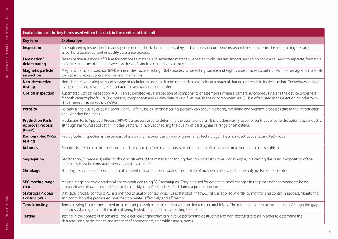
Explanations of the key terms used within this unit, in the context of this unit
Key term Explanation
Inspection An engineering inspection is usually performed to check the accuracy, safety and reliability of components, assemblies or systems. Inspection may be carried out as part of a quality control or quality assurance process.
Lamination/delaminating
Delamination is a mode of failure for composite materials. In laminated materials, repeated cyclic stresses, impact, and so on can cause layers to separate, forming a mica-like structure of separate layers, with significant loss of mechanical toughness.
Magnetic particle inspection
Magnetic particle Inspection (MPI) is a non-destructive testing (NDT) process for detecting surface and slightly subsurface discontinuities in ferromagnetic materials such as iron, nickel, cobalt, and some of their alloys.
Non-destructive testing
Non-destructive testing refers to a range of techniques used to determine the characteristics of a material that do not result in its destruction. Techniques include dye penetration, ultrasonic, electromagnetic and radiographic testing.
Optical inspection Automated Optical Inspection (AOI) is an automated visual inspection of components or assemblies where a camera autonomously scans the device under test for both catastrophic failure (e.g. missing component) and quality defects (e.g. fillet size/shape or component skew). It is often used in the electronics industry to check printed circuit boards (PCBs).
Porosity Porosity is the quality of being porous, or full of tiny holes. In engineering, porosity can occur in casting, moulding and welding processes due to the introduction or air or other impurities.
Production Parts Approval Process (PPAP)
Production Parts Approval Process (PPAP) is a process used to determine the quality of parts. It is predominantly used for parts supplied to the automotive industry, although has found application in other sectors. It involves checking the quality of parts against a range of set criteria.
Radiographic X-Ray testing
Radiographic inspection is the process of evaluating material using x-ray or gamma-ray technology. It is a non-destructive testing technique.
Robotics Robotics is the use of computer-controlled robots to perform manual tasks. In engineering this might be on a production or assembly line.
Segregation Segregation (in materials) refers to the constituents of the materials changing throughout its structure. For example, in a casting the grain composition of the material will not be consistent throughout the cast item.
Shrinkage Shrinkage is a process of contraction of a material. It often occurs during the cooling of moulded metals, and in the polymerisation of plastics.
SPC moving range chart
Moving range charts are statistical charts produced using SPC techniques. They are used for detecting small changes in the process for components being produced and allow errors and faults to be quickly identified and rectified during a production run.
Statistical Process Control (SPC)
Statistical process control (SPC) is a method of quality control which uses statistical methods. SPC is applied in order to monitor and control a process. Monitoring and controlling the process ensures that it operates effectively and efficiently.
Tensile testing Tensile testing is a test performed on a test sample which is subjected to a controlled tension until it fails. The results of the test are often a force/elongation graph or a stress/strain graph for the material being tested. It is a destructive testing technique.
Testing Testing in the context of mechanical and electrical engineering can involve performing destructive and non-destructive tests in order to determine the characteristics, performance and integrity of components, assemblies and systems.
OC
R LE
VEL
3 C
AM
BRID
GE
TEC
HN
ICA
LS IN
EN
GIN
EERI
NG
INSP
ECTI
ON
AN
D T
ESTI
NG
7
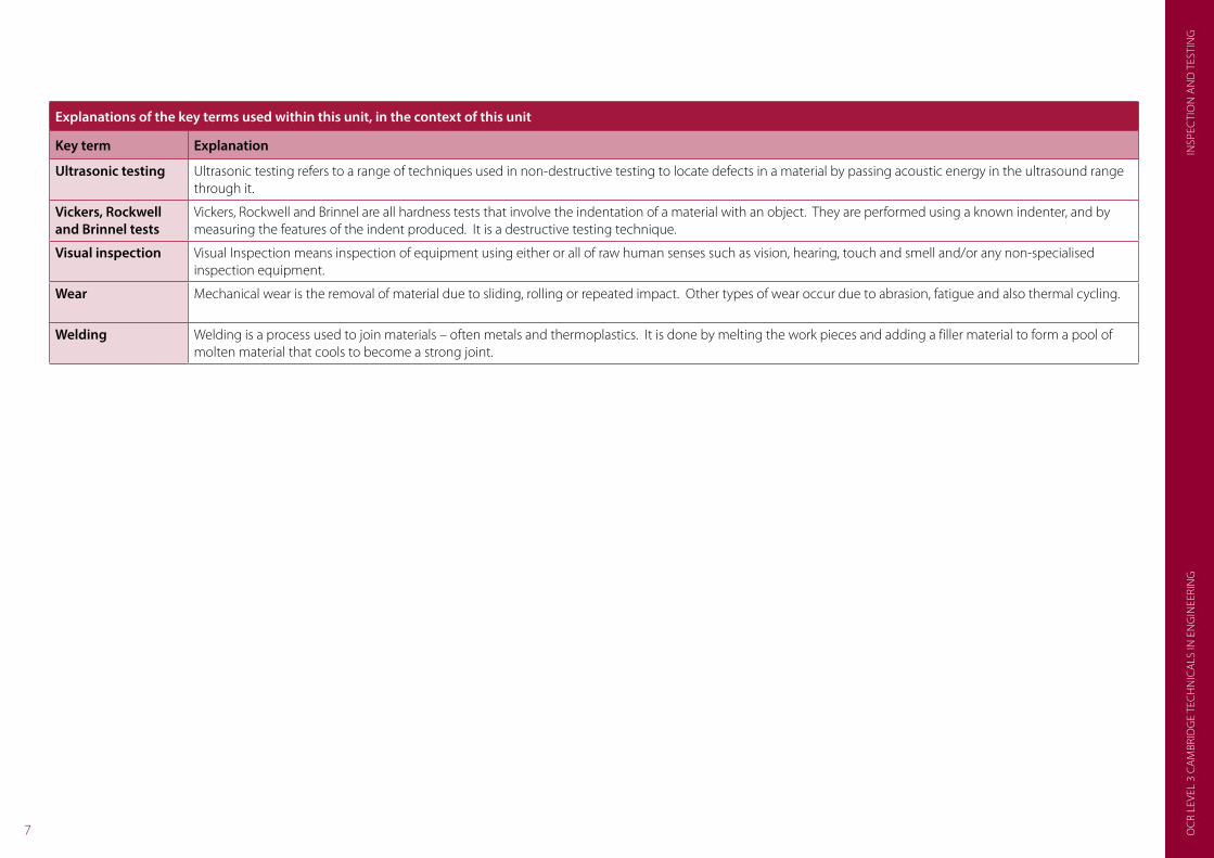
Explanations of the key terms used within this unit, in the context of this unit
Key term Explanation
Ultrasonic testing Ultrasonic testing refers to a range of techniques used in non-destructive testing to locate defects in a material by passing acoustic energy in the ultrasound range through it.
Vickers, Rockwell and Brinnel tests
Vickers, Rockwell and Brinnel are all hardness tests that involve the indentation of a material with an object. They are performed using a known indenter, and by measuring the features of the indent produced. It is a destructive testing technique.
Visual inspection Visual Inspection means inspection of equipment using either or all of raw human senses such as vision, hearing, touch and smell and/or any non-specialised inspection equipment.
Wear Mechanical wear is the removal of material due to sliding, rolling or repeated impact. Other types of wear occur due to abrasion, fatigue and also thermal cycling.
Welding Welding is a process used to join materials – often metals and thermoplastics. It is done by melting the work pieces and adding a filler material to form a pool of molten material that cools to become a strong joint.

OC
R LEVEL 3 CA
MBRID
GE TEC
HN
ICA
LS IN EN
GIN
EERING
INSPEC
TION
AN
D TESTIN
G
8
Some common misconceptions and guidance on how they could be overcome
What is the misconception? How can this be overcome? Resources which could help
SPC moving range chart – handling data
Learners may need to recap statistical mathematics before attempting problems involving SPC moving range charts.
The following resource provides revision with statistics, calculating mean (average) and with graph plotting.
http://www.mathsisfun.com/data/index.html
MISCONCEPTIONS

OC
R LE
VEL
3 C
AM
BRID
GE
TEC
HN
ICA
LS IN
EN
GIN
EERI
NG
INSP
ECTI
ON
AN
D T
ESTI
NG
9
SUGGESTED ACTIVITIESLO No: 1
LO Title: Understand how inspection and testing methods and processes improve quality control
Title of suggested activity Suggested activities Suggested timings Also related to
Introduction to inspection and testing
Teachers could begin with a basic introduction to the reasons for performing quality assurance and quality control – explaining the differences between inspection and testing. The following website provides a short introduction: http://www.bbc.co.uk/schools/gcsebitesize/design/textiles/analysisevaluationrev3.shtml
Learners could undertake an investigation of the applications of inspection and testing in engineering manufacture, highlighting examples of both.
1 hour
Production Parts Approval Process (PPAP)
Production Parts Approval Process (PPAP) is a quality assurance technique commonly used in the automotive industry that allows producers to evaluate the quality of components and assemblies received from their suppliers. It is also used in other sectors.
In many cases PPAP follows a common standard.
Learners could investigate the implementation of PPAP, and the standard criteria that are used for component/sub-assembly evaluation. They could be able to evaluate a component against a PPAP, or develop their own PPAP for a given component.
The following web resources may prove useful: http://sites.google.com/site/kellystechlibrary/home/ppap-production-part-approval-process which explains the PPAP process and http://ppapdocuments.com/ which provides a range of PPAP documents.
2 hours
First Off and Last Off inspection (FOLO)
First Off Last Off (FOLO) is a quality assurance technique used to determine the quality of manufactured items. In this technique, the quality of the first item manufactured is checked to ensure correct process set-up, and the last item manufactured checked to ensure that further batch manufacture will be accurate. Usually, intermediate quality checks are made.
Learners could investigate FOLO and suggest engineered components and assemblies where it could be applied.
The following PDF document from the United Nations Industrial Development Organisation explains FOLO and provides further guidance on product quality: http://www.unido.org/fileadmin/media/documents/pdf/tcb_product_quality.pdf
2 hours

OC
R LEVEL 3 CA
MBRID
GE TEC
HN
ICA
LS IN EN
GIN
EERING
INSPEC
TION
AN
D TESTIN
G
10
Title of suggested activity Suggested activities Suggested timings Also related to
Statistical Process Control (SPC) - introduction
Statistical Process Control (SPC) refers to a whole range of techniques for monitoring, controlling and improving a process through the use of statistical techniques.
Teachers could begin by introducing learners to SPC, and highlighting where it can be applied in practice.
The following provides and introduction to SPC: http://www.winspc.com/what-is-spc
Teachers could develop simple statistical (SPC) problems for learners to solve. This could involve taking measurements from a range of common parts or components.
2 hours Unit 1 LO6
SPC – moving range charts
See Lesson Element SPC – moving range charts
A common tools used in SPC is the moving range chart (and also the moving average chart). These are used for detecting small changes in a process for components being produced and allow errors and faults to be quickly identified and rectified during a production run.
The following website explains how to construct and interpret an SPC moving range chart: http://qualityamerica.com/LSS-Knowledge-Center/statisticalprocesscontrol/individual-x_moving_range_charts.php
Teachers could develop problems for learners to solve that require the use of an SPC chart. This might also require learners to make actual measurements to determine the quality of components.
This also provides an opportunity to develop charts with the aid of ICT (e.g. spreadsheets). The following spreadsheet may prove useful: http://www.gkn.com/landsystems/brands/rockford/supplierdocuments/spcindividualandmovingrangerevisionk.xls
3 hours Unit 1 LO6
Scheduling inspection and testing (inspection and test plans)
Inspection and test plans (ITPs), sometimes called a quality inspection plan are a way in which to schedule inspection or verification activities.
Teachers could begin with an introduction to inspection and test plans, which could include their relevance to satisfying ISO 9001. The following may prove a useful introduction and includes example test plans: http://www.qualitysystems.com/support/pages/inspection-and-test-plans
Learners could develop their own ITPs for an engineered product or assembly.
2 hours

OC
R LE
VEL
3 C
AM
BRID
GE
TEC
HN
ICA
LS IN
EN
GIN
EERI
NG
INSP
ECTI
ON
AN
D T
ESTI
NG
11
LO No: 2
LO Title: Understand how defects can occur in manufacturing materials, processes and components
Title of suggested activity Suggested activities Suggested timings Also related to
Types of defects in materials – cracking, lamination and segregation
Learners may be familiar with some failure modes of materials. The following video illustrates failure of components caused by fracture, distortion, wear and corrosion and could be used as an introduction to failure modes and failure analysis: http://www.youtube.com/watch?v=85HxmnLEkwM
Learners could investigate other common defects in materials including cracking, delaminating and segregation. Videos could be used to illustrate these or practical examples could be shown if available.
The following explains crack propagation: http://www.youtube.com/watch?v=4CbWbyu0oCM and the following delamination: http://www.twi-global.com/technical-knowledge/faqs/process-faqs/faq-what-is-the-difference-between-debonding-and-delamination-in-adhesive-joints-coatings-and-composites-and-other-defects-found/
2 hours Unit 2 LO4
Unit 11 LO2
Types of defects in materials – shrinkage, porosity and inclusions
Further defects include shrinkage which is common in moulding and polymerisation, porosity which can occur in casting, moulding and welding and inclusions which are foreign particles present in a material due to impurities.
All of these defects may occur in the manufacture of components and assemblies and require identifying with suitable quality control checks.
Learners could investigate these types of defect though the use of web-based resources or teachers may be able to explain these using practical examples. The following explains porosity in welds: http://www.twi-global.com/technical-knowledge/job-knowledge/defects-imperfections-in-welds-porosity-042/
2 hours Unit 2 LO4
Unit 11 LO2
Types of defects in manufacturing processes – forging and casting
Forging and casting are two further manufacturing techniques where defects can occur.
Defects can include shrinkage, flash projections, grain separation, blowholes and pinholes, cavities protrusions and incorrect dimensions.
Learners could investigate common defects in forging and casting, how these can be identified, and if they can be rectified.
The following web site explains some of the common defects that can occur in casting: http://www.afsinc.org/content.cfm?ItemNumber=6944
2 hours Unit 2 LO4
Unit 11 LO2
SUGGESTED ACTIVITIES

OC
R LEVEL 3 CA
MBRID
GE TEC
HN
ICA
LS IN EN
GIN
EERING
INSPEC
TION
AN
D TESTIN
G
12
Title of suggested activity Suggested activities Suggested timings Also related to
Types of defects in manufacturing processes – welding
Common defects that can occur in welds include porosity, lack of fusion, craters and burn through. Welding defects can be detected using visual inspection and more detailed destructive and non-destructive testing.
Learners could investigate common defects in welds, the effects of these defects, how they could be identified, and if they can be rectified.
The following web resource illustrates some common defects in welds: http://www.millerwelds.com/resources/articles/Common-MIG-Weld-Defects-GMAW/
2 hours Unit 2 LO4
Unit 11 LO2
Types of defects in manufacturing processes – coatings
A coating is a layer of substance spread over the surface of a material to provide protection or decoration. Coatings might, for example, be used to provide protection against rusting.
Coatings can include paints, lacquers, vaporised and chemically deposited materials, anodised metals etc.
Coatings can fail due to a number of reasons including poor adhesion, inadequate or inconsistent application, presence of contaminants etc.
Learners could investigate the application of different types of coatings, how defects could occur, how these can be identified and how they could be rectified.
The following website illustrates some common coating failures: http://www.amteccorrosion.co.uk/coatingfailuresguide.html
2 hours Unit 2 LO4
Unit 11 LO2
In-service defects In-service defects are defects that occur during use. These include defects caused through wear, fatigue and as a result of other causes such as stress, corrosion and fracturing.
Learners could investigate the types of defects that occur in components and assemblies, the causes and effects of these failures and how they are related with material and manufacturing defects.
The following website includes a number of case studies along with photographs showing defects, their cause and effect: http://materials.open.ac.uk/mem/mem_mf.htm
2 hours Unit 2 LO4
Unit 11 LO2

OC
R LE
VEL
3 C
AM
BRID
GE
TEC
HN
ICA
LS IN
EN
GIN
EERI
NG
INSP
ECTI
ON
AN
D T
ESTI
NG
13
LO No: 3
LO Title: Understand how destructive testing methods are used for quality assurance in manufacturing
Title of suggested activity Suggested activities Suggested timings Also related to
Introduction to destructive testing
Destructive testing refers to testing that can be used to determine the characteristics of a material but that result in its destruction. Destructive testing techniques include tensile testing, impact testing and hardness testing.
Teachers could begin with an overview of destructive testing, leaving learners to investigate where destructive testing might be applied in an engineering context and the range of techniques used. This could relate to both testing during product design and also during manufacture in order to provide quality assurance.
The following provides a brief introduction to destructive testing: http://www.inspecta.com/en/Our-Services/Testing/Destructive-Testing/
2 hours
Destructive test methods – Charpy Notch test
The Charpy Notch Test, also known as the Charpy V-notch test, is a standardised high strain-rate test which determines the amount of energy absorbed by a material during fracture. It involves striking a test sample with a mass.
Teachers could use resources, such as the following to explain and show the Charpy test: http://www.twi-global.com/technical-knowledge/faqs/material-faqs/faq-what-is-charpy-testing/ (explanation) and
http://www.youtube.com/watch?v=tpGhqQvftAo (video of test being performed).
It might be possible for teachers to access resources in order to demonstrate the Charpy test practically.
Teachers could provide data to enable learners to evaluate Charpy test results for different materials at different temperatures.
2 hours Unit 1 LO1
Unit 2 LO4
Destructive test methods – tensile testing
See Lesson Element Destructive test methods – Charpy Notch test
Tensile testing is a test performed on a test sample which is subjected to a controlled tension until it fails. The results of the test are often a force/elongation graph or a stress/strain graph for the material being tested. This graph can be used to determine the properties of the material.
Learners could already be familiar with tensile testing from previous studies. The following video explains and demonstrates tensile testing being performed: http://www.youtube.com/watch?v=D8U4G5kcpcM
If the teacher has access to suitable resources then a practical demonstration of tensile testing might be possible.
Teachers could provide data for learners to identify the tensile characteristics of different materials.
2 hours Unit 1 LO1
Unit 2 LO4
SUGGESTED ACTIVITIES

OC
R LEVEL 3 CA
MBRID
GE TEC
HN
ICA
LS IN EN
GIN
EERING
INSPEC
TION
AN
D TESTIN
G
14
Title of suggested activity Suggested activities Suggested timings Also related to
Destructive test methods – Vickers, Rockwell and Brinnel hardness tests
Vickers, Rockwell and Brinnel are all hardness tests that involve the indentation of a material with an object. They are performed using a known indenter, and by measuring the features of the indent produced. They are used to determine the hardness of a material.
Learners could investigate the how each of these tests are performed including the reason for three different hardness tests. They could summarise their findings including similarities and differences. The following videos illustrate and explain each hardness test:
http://www.youtube.com/watch?v=G2JGNlIvNC4 (Rockwell)
http://www.youtube.com/watch?v=RJXJpeH78iU (Brinnel)
http://www.youtube.com/watch?v=7Z90OZ7C2jI (Vickers).
If access to suitable equipment is available, learners could be able to observe hardness testing taking place practically.
With the use of suitable data, learners could compare hardness test results and evaluate the hardness of a range of different materials.
3 hours Unit 1 LO1
Unit 2 LO4
Advantages and disadvantages of destructive testing
Learners could conclude this learning outcome by summarising and comparing destructive testing techniques that can be used to assure quality during manufacturing. This could include the advantages and disadvantages of destructive testing in general and the application, advantages and disadvantages of each technique individually. This could be in the form of a presentation.
2 hours

OC
R LE
VEL
3 C
AM
BRID
GE
TEC
HN
ICA
LS IN
EN
GIN
EERI
NG
INSP
ECTI
ON
AN
D T
ESTI
NG
15
LO No: 4
LO Title: Understand how non-destructive testing methods are used for quality assurance in a manufacturing environment
Title of suggested activity Suggested activities Suggested timings Also related to
Introduction to non-destructive testing (NDT)
Non-destructive testing refers to a range of techniques used to determine the characteristics of a material that do not result in its destruction. Techniques include dye penetration, ultrasonic, electromagnetic and radiographic testing.
Teachers could begin this learning outcome with an introduction and overview of NDT.
The following videos from the British Institute of non-Destructive Testing (BINDT) and The Welding Institute (TWI) may prove useful stimulus for discussion: http://www.bindt.org/videos/ (BINDT - The Unseen World of NDT) http://www.youtube.com/watch?v=tlE3eK0g6vU (TWI- overview of NDT techniques).
1 hour
NDT test methods – visual inspection
Visual Inspection means inspection of equipment using either or all of raw human senses such as vision, hearing, touch and smell and/or any non-specialised inspection equipment. It is a technique which is widely used in quality assurance during manufacturing.
Learners could investigate applications of visual inspection, summarising how it is performed and its advantages and disadvantages. The following videos show visual inspection being performed in two different scenarios:
http://www.youtube.com/watch?v=9VYA9ufb4Jc (visual inspection of a PCB) http://www.youtube.com/watch?v=xDajhAzG16k (visual inspection of jet engine turbine blades)
It may be possible for learners to undertake a practical visual inspection task, with access to suitable resources.
2 hours
NDT test methods – liquid (dye) penetrant testing
Dye penetration (penetrant) inspection (DPI), also called liquid penetrant inspection (LPI) or penetrant testing (PT), is a widely applied and low-cost inspection method used to locate surface-breaking defects in all non-porous materials (metals, plastics, or ceramics).
Teachers could use video resources to show and explain liquid (dye) penetrant testing to learners such as: http://www.youtube.com/watch?v=xEK-c1pkTUI
The following also explains the process: http://www.bindt.org/What-is-NDT/Liquid-penetrant-inspection/
Learners could investigate the applications of liquid (dye) penetrant testing, including its advantages and disadvantages.
Due to its relatively low-cost implementation, it may be possible for learners to undertake a practical activity.
2 hours
SUGGESTED ACTIVITIES

OC
R LEVEL 3 CA
MBRID
GE TEC
HN
ICA
LS IN EN
GIN
EERING
INSPEC
TION
AN
D TESTIN
G
16
Title of suggested activity Suggested activities Suggested timings Also related to
NDT test methods – magnetic particle testing
Magnetic particle Inspection (MPI) is a non-destructive testing (NDT) process for detecting surface and slightly subsurface discontinuities in ferromagnetic materials such as iron, nickel, cobalt, and some of their alloys.
Again, web-based resources could be used by teachers to explain and illustrate this technique, such as: http://www.bindt.org/What-is-NDT/Magnetic-particle-inspection-MPI/ (explanation) and http://www.youtube.com/watch?v=qpgcD5k1494 (video).
Learners could investigate its application, advantages and disadvantages.
Due to its higher implementation cost, teachers might be able to arrange a suitable industrial visit to see this, and other NDT techniques being undertaken in practice.
2 hours
NDT test methods – ultrasonic testing
Lesson Element NDT test methods – ultrasonic testing
Ultrasonic testing refers to a range of techniques used in non-destructive testing to locate defects in a material by passing acoustic energy in the ultrasound range through it. There are several different types of ultrasonic testing used in NDT.
Teachers could again use suitable web based resources to explain and illustrate this NDT technique, such as: http://www.bindt.org/What-is-NDT/Ultrasonic-flaw-detection/ (explanation) and http://www.youtube.com/watch?v=UM6XKvXWVFA (video).
Learners could investigate this technique more fully, and its applications.
Ultrasonic testing requires more expensive equipment, and so it might only be possible to see this practically in a work-based setting.
2 hours
NDT test methods – radiographic testing
Radiographic inspection is the process of evaluating material using x-ray or gamma-ray technology.
The following explain and illustrate radiographic testing: http://www.bindt.org/What-is-NDT/Radiography/ (explanation) and http://www.youtube.com/watch?v=VscasN8jgfo (video).
Learners could investigate the range of different types of radiographic testing, and their particular applications.
2 hours
NDT test methods – eddy current testing
Eddy-current testing uses electromagnetic induction to detect flaws in conductive materials.
The following web-based resources explain and illustrate eddy current testing: http://www.bindt.org/What-is-NDT/Eddy-current-testing/ (explanation) and http://www.youtube.com/watch?v=9A5fQtOwnzw (video).
Learners could investigate further the application of eddy current testing, summarising how it is performed, and the results it produces.
2 hours
Advantages and disadvantages of non-destructive testing
Learners could conclude this learning outcome by summarising the range of different NDT techniques, their advantages and disadvantages, and how they might be applied in engineering manufacturing. This could be in the form of a presentation.
2 hours

OC
R LE
VEL
3 C
AM
BRID
GE
TEC
HN
ICA
LS IN
EN
GIN
EERI
NG
INSP
ECTI
ON
AN
D T
ESTI
NG
17
LO No: 5
LO Title: Understand automatic inspection and testing techniques which are used in manufacturing
Title of suggested activity Suggested activities Suggested timings Also related to
Automatic inspection techniques - robotics
Robotics is the use of computer-controlled robots to perform manual tasks. In engineering this could be used on a production or assembly line to perform quality assurance activities – such as extracting and inspecting components.
Learners could investigate the applications of computers in quality assurance operations, which could include inspection and testing.
The following video shows robots being used for the visual inspection of parts. Learners could note the reasons for using an automated robotic solution in this application: http://www.youtube.com/watch?v=qL10pqrDv-0
It may be possible for teachers to arrange an industrial visit in order that learners can see automatic inspection techniques in action.
2 hours Unit 17 LO1
Automatic inspection techniques – computer vision and optical inspection
Computer vision is a field that includes methods for acquiring, processing, analysing, and understanding images. It can be used in automatic inspection to check the quality of components.
Learners could investigate computer vision applications.
The following website includes a video explaining how computer vision can be applied in quality assurance: http://www.microscan.com/en-us/Technology/MachineVisionSystems/machine-vision.aspx (machine vision).
Automated Optical Inspection (AOI) is another technique for the automated visual inspection of components or assemblies where a camera autonomously scans the device under test for both catastrophic failure (e.g. missing component) and quality defects (e.g. fillet size/shape or component skew). It is often used in the electronics industry to check printed circuit boards (PCBs).
Learners could investigate the similarities between computer vision and AOI. The following website explains now AOI can be used to inspect printed circuit boards (PCBs) and some of its requirements: http://www.radio-electronics.com/info/t_and_m/ate/aoi-automatic-automated-optical-inspection.php (AOI).
Suitable case studies could also be used, such as the following which presents automatic inspection of chocolate bars: http://www.stemmer-imaging.co.uk/media/uploads/websites/documents/applications/en_DE-Application-Kdorf-Chocolate-201211.pdf
2 hours Unit 17 LO1
SUGGESTED ACTIVITIES

OC
R LEVEL 3 CA
MBRID
GE TEC
HN
ICA
LS IN EN
GIN
EERING
INSPEC
TION
AN
D TESTIN
G
18
SUGGESTED ACTIVITIESTitle of suggested activity Suggested activities Suggested timings Also related to
Automatic inspection techniques – co-ordinate measurement
A coordinate measuring machine (CMM) is a device for measuring the physical geometrical characteristics of an object. This machine may be manually controlled by an operator or it may be automated using computer control. Measurements are defined by a probe attached to the third moving axis of this machine.
Teachers could use suitable videos, such as the following, to explain the operation of a CMM: http://www.youtube.com/watch?v=844UiRBVxlY
Learners could analyse case studies of how a CMM is used within quality assurance. The following case studies may be useful:
http://www.nikonmetrology.com/en_EU/Literature-Downloads (case studies of CMM).
Teachers may be able to access a physical CMM to demonstrate to learners.
2 hours
Advantages and limitations of automatic inspection in quality assurance
Learners could summarise the advantages and limitations of automatic inspection through a presentation or other means. This could be related to their application in manufacturing, and teachers could adopt suitable case studies on which learners could base their findings.
2 hours
Automatic test equipment (ATE)
Automated test equipment (ATE) is computer-controlled equipment that tests devices for functionality and performance. ATE also conducts stress testing with minimal human interaction. ATE includes the control hardware, sensors, and software that collects and analyses the test results. It is often used on electronic devices and assemblies, such as printed circuit boards. ATE can be extended to other manufacturing situations.
Learners could investigate the application of ATE in manufacturing. Investigation carried out by learners could include scope of use, speed of operation, limitations and advantages, what is being detected, protocols (e.g. GPIB) and setting up.
The following video shows ATE being used to test printed circuit boards: http://www.youtube.com/watch?v=YegtDW42peg
2 hours Unit 6 LO5

OC
R LE
VEL
3 C
AM
BRID
GE
TEC
HN
ICA
LS IN
EN
GIN
EERI
NG
INSP
ECTI
ON
AN
D T
ESTI
NG
19
OCR Resources: the small printOCR’s resources are provided to support the teaching of OCR specifications, but in no way constitute an endorsed teaching method that is required by the Board, and the decision to use them lies with the individual teacher. Whilst every effort is made to ensure the accuracy of the content, OCR cannot be held responsible for any errors or omissions within these resources.
© OCR 2015 - This resource may be freely copied and distributed, as long as the OCR logo and this message remain intact and OCR is acknowledged as the originator of this work.
OCR acknowledges the use of the following content: English and Maths icon: Air0ne/Shutterstock.com. Thumbs up and down icons: alexwhite/Shutterstock.com
Please get in touch if you want to discuss the accessibility of resources we offer to support delivery of our qualifications: [email protected]
We’d like to know your view on the resources we produce. By clicking on the ‘Like’ or ‘Dislike’ button you can help us to ensure that our resources work for you. When the email template pops up please add additional comments if you wish and then just click ‘Send’. Thank you.
If you do not currently offer this OCR qualification but would like to do so, please complete the Expression of Interest Form which can be found here: www.ocr.org.uk/expression-of-interest

TECHNICALSCambridge
For staff training purposes and as part of our quality assurance programme your call may be recorded or monitored. © OCR 2015 Oxford Cambridge and RSA Examinations is a Company Limited by Guarantee. Registered in England. Registered office 1 Hills Road, Cambridge CB1 2EU. Registered company number 3484466. OCR is an exempt charity.
Contact us
Telephone: 02476 851509 Email: [email protected]
Staff at the OCR Customer Contact Centre are available to take your call
between 8am and 5.30pm, Monday to Friday.