campus lan reference architecture - ibm · a new campus lan design that meets campus ... are...
TRANSCRIPT

REFERENCE ARCHITECTURE
Copyright © 2009, Juniper Networks, Inc.
Campus LaN RefeReNCe aRChiteCtuRe
Practices, Technologies and Products for Designing Modern Campus LANs
� Copyright © 2009, Juniper Networks, Inc.
RefeReNCe aRChiteCtuRe - Campus LaN
Table of Contentsintroduction . . . . . . . . . . . . . . . . . . . . . . . . . . . . . . . . . . . . . . . . . . . . . . . . . . . . . . . . . . . . . . . . . . . . . . . . . . . . . . . . . . . . . . . . 5
scope . . . . . . . . . . . . . . . . . . . . . . . . . . . . . . . . . . . . . . . . . . . . . . . . . . . . . . . . . . . . . . . . . . . . . . . . . . . . . . . . . . . . . . . . . . . . . . 5
solution profile Overview . . . . . . . . . . . . . . . . . . . . . . . . . . . . . . . . . . . . . . . . . . . . . . . . . . . . . . . . . . . . . . . . . . . . . . . . . . . . . 5
Services Needed in the Campus LAN . . . . . . . . . . . . . . . . . . . . . . . . . . . . . . . . . . . . . . . . . . . . . . . . . . . . . . . . . . . . . . . 5
Security . . . . . . . . . . . . . . . . . . . . . . . . . . . . . . . . . . . . . . . . . . . . . . . . . . . . . . . . . . . . . . . . . . . . . . . . . . . . . . . . . . . 5
LAN Connectivity . . . . . . . . . . . . . . . . . . . . . . . . . . . . . . . . . . . . . . . . . . . . . . . . . . . . . . . . . . . . . . . . . . . . . . . . . . . . 6
WAN Connectivity . . . . . . . . . . . . . . . . . . . . . . . . . . . . . . . . . . . . . . . . . . . . . . . . . . . . . . . . . . . . . . . . . . . . . . . . . . . 6
Internet Access . . . . . . . . . . . . . . . . . . . . . . . . . . . . . . . . . . . . . . . . . . . . . . . . . . . . . . . . . . . . . . . . . . . . . . . . . . . . . 6
Remote Access Services. . . . . . . . . . . . . . . . . . . . . . . . . . . . . . . . . . . . . . . . . . . . . . . . . . . . . . . . . . . . . . . . . . . . . . 6
High Performance . . . . . . . . . . . . . . . . . . . . . . . . . . . . . . . . . . . . . . . . . . . . . . . . . . . . . . . . . . . . . . . . . . . . . . . . . . 6
High Availability. . . . . . . . . . . . . . . . . . . . . . . . . . . . . . . . . . . . . . . . . . . . . . . . . . . . . . . . . . . . . . . . . . . . . . . . . . . . . 6
Centralized Management . . . . . . . . . . . . . . . . . . . . . . . . . . . . . . . . . . . . . . . . . . . . . . . . . . . . . . . . . . . . . . . . . . . . . 6
Campus LaN Design Considerations . . . . . . . . . . . . . . . . . . . . . . . . . . . . . . . . . . . . . . . . . . . . . . . . . . . . . . . . . . . . . . . . . . . 7
Enterprise Computing Trends . . . . . . . . . . . . . . . . . . . . . . . . . . . . . . . . . . . . . . . . . . . . . . . . . . . . . . . . . . . . . . . . . . . . . 7
The Proliferation of Unified Communications . . . . . . . . . . . . . . . . . . . . . . . . . . . . . . . . . . . . . . . . . . . . . . . . . . . . 7
Bandwidth-Hungry Applications . . . . . . . . . . . . . . . . . . . . . . . . . . . . . . . . . . . . . . . . . . . . . . . . . . . . . . . . . . . . . . . 7
User Productivity. . . . . . . . . . . . . . . . . . . . . . . . . . . . . . . . . . . . . . . . . . . . . . . . . . . . . . . . . . . . . . . . . . . . . . . . . . . . 7
Increasing Focus on Security. . . . . . . . . . . . . . . . . . . . . . . . . . . . . . . . . . . . . . . . . . . . . . . . . . . . . . . . . . . . . . . . . . 7
Demand for Wireless Services. . . . . . . . . . . . . . . . . . . . . . . . . . . . . . . . . . . . . . . . . . . . . . . . . . . . . . . . . . . . . . . . . 7
Server Centralization and Data Center Consolidation. . . . . . . . . . . . . . . . . . . . . . . . . . . . . . . . . . . . . . . . . . . . . . 8
Infrastructure Solutions . . . . . . . . . . . . . . . . . . . . . . . . . . . . . . . . . . . . . . . . . . . . . . . . . . . . . . . . . . . . . . . . . . . . . . . . . . 8
Campus architecture Overview . . . . . . . . . . . . . . . . . . . . . . . . . . . . . . . . . . . . . . . . . . . . . . . . . . . . . . . . . . . . . . . . . . . . . . . . 9
Layered Approach . . . . . . . . . . . . . . . . . . . . . . . . . . . . . . . . . . . . . . . . . . . . . . . . . . . . . . . . . . . . . . . . . . . . . . . . . . . . . . . 9
Benefits and Challenges to the Layered Approach . . . . . . . . . . . . . . . . . . . . . . . . . . . . . . . . . . . . . . . . . . . . . . . . 9
A Network Revolution . . . . . . . . . . . . . . . . . . . . . . . . . . . . . . . . . . . . . . . . . . . . . . . . . . . . . . . . . . . . . . . . . . . . . . . 10
Access Layer . . . . . . . . . . . . . . . . . . . . . . . . . . . . . . . . . . . . . . . . . . . . . . . . . . . . . . . . . . . . . . . . . . . . . . . . . . . . . . 10
Access Layer Design Considerations . . . . . . . . . . . . . . . . . . . . . . . . . . . . . . . . . . . . . . . . . . . . . . . . . . . . . . . . . . . . . . 11
Wired Port Connectivity . . . . . . . . . . . . . . . . . . . . . . . . . . . . . . . . . . . . . . . . . . . . . . . . . . . . . . . . . . . . . . . . . . . . . 11
WLAN Connectivity . . . . . . . . . . . . . . . . . . . . . . . . . . . . . . . . . . . . . . . . . . . . . . . . . . . . . . . . . . . . . . . . . . . . . . . . . 11
PoE . . . . . . . . . . . . . . . . . . . . . . . . . . . . . . . . . . . . . . . . . . . . . . . . . . . . . . . . . . . . . . . . . . . . . . . . . . . . . . . . . . . . . . 12
VLAN and Spanning Tree Protocol. . . . . . . . . . . . . . . . . . . . . . . . . . . . . . . . . . . . . . . . . . . . . . . . . . . . . . . . . . . . . 12
Using Layer 2 versus Layer 3 at the Access Layer. . . . . . . . . . . . . . . . . . . . . . . . . . . . . . . . . . . . . . . . . . . . . . . . 13
Considerations for Implementing Unified Communications . . . . . . . . . . . . . . . . . . . . . . . . . . . . . . . . . . . . . . . 14
Threat Containment . . . . . . . . . . . . . . . . . . . . . . . . . . . . . . . . . . . . . . . . . . . . . . . . . . . . . . . . . . . . . . . . . . . . . . . . 15
Modular Chassis Technology . . . . . . . . . . . . . . . . . . . . . . . . . . . . . . . . . . . . . . . . . . . . . . . . . . . . . . . . . . . . . . . . . 15
Access Layer Solutions. . . . . . . . . . . . . . . . . . . . . . . . . . . . . . . . . . . . . . . . . . . . . . . . . . . . . . . . . . . . . . . . . . . . . . . . . . 15
Scalable Access Solutions with Virtual Chassis Technology. . . . . . . . . . . . . . . . . . . . . . . . . . . . . . . . . . . . . . . . 15
Wireless Solutions . . . . . . . . . . . . . . . . . . . . . . . . . . . . . . . . . . . . . . . . . . . . . . . . . . . . . . . . . . . . . . . . . . . . . . . . . 18
aggregation Layer . . . . . . . . . . . . . . . . . . . . . . . . . . . . . . . . . . . . . . . . . . . . . . . . . . . . . . . . . . . . . . . . . . . . . . . . . . . . . . . . . . 19
Aggregation Layer Design Considerations. . . . . . . . . . . . . . . . . . . . . . . . . . . . . . . . . . . . . . . . . . . . . . . . . . . . . . . . . . 19

Copyright © 2009, Juniper Networks, Inc. �
RefeReNCe aRChiteCtuRe - Campus LaN
Segmentation/Virtualization . . . . . . . . . . . . . . . . . . . . . . . . . . . . . . . . . . . . . . . . . . . . . . . . . . . . . . . . . . . . . . . . . 19
Aggregation Layer Solutions . . . . . . . . . . . . . . . . . . . . . . . . . . . . . . . . . . . . . . . . . . . . . . . . . . . . . . . . . . . . . . . . . . . . . 20
Scalable Aggregation Layer Solutions . . . . . . . . . . . . . . . . . . . . . . . . . . . . . . . . . . . . . . . . . . . . . . . . . . . . . . . . . 20
Core Layer . . . . . . . . . . . . . . . . . . . . . . . . . . . . . . . . . . . . . . . . . . . . . . . . . . . . . . . . . . . . . . . . . . . . . . . . . . . . . . . . . . . . . . . . �1
Core Layer Considerations. . . . . . . . . . . . . . . . . . . . . . . . . . . . . . . . . . . . . . . . . . . . . . . . . . . . . . . . . . . . . . . . . . . . . . . 21
Core Layer Solutions . . . . . . . . . . . . . . . . . . . . . . . . . . . . . . . . . . . . . . . . . . . . . . . . . . . . . . . . . . . . . . . . . . . . . . . . . . . 21
High Performance Core Layer Solutions . . . . . . . . . . . . . . . . . . . . . . . . . . . . . . . . . . . . . . . . . . . . . . . . . . . . . . . 21
Is the Core Layer Essential? . . . . . . . . . . . . . . . . . . . . . . . . . . . . . . . . . . . . . . . . . . . . . . . . . . . . . . . . . . . . . . . . . . . . . 22
Challenges and Benefits . . . . . . . . . . . . . . . . . . . . . . . . . . . . . . . . . . . . . . . . . . . . . . . . . . . . . . . . . . . . . . . . . . . . 22
Consolidating the Core and Aggregation Layers . . . . . . . . . . . . . . . . . . . . . . . . . . . . . . . . . . . . . . . . . . . . . . . . . 23
WaN edge integration . . . . . . . . . . . . . . . . . . . . . . . . . . . . . . . . . . . . . . . . . . . . . . . . . . . . . . . . . . . . . . . . . . . . . . . . . . . . . . . �4
WAN Edge Considerations . . . . . . . . . . . . . . . . . . . . . . . . . . . . . . . . . . . . . . . . . . . . . . . . . . . . . . . . . . . . . . . . . . . . . . . 24
Connectivity . . . . . . . . . . . . . . . . . . . . . . . . . . . . . . . . . . . . . . . . . . . . . . . . . . . . . . . . . . . . . . . . . . . . . . . . . . . . . . . 24
HA . . . . . . . . . . . . . . . . . . . . . . . . . . . . . . . . . . . . . . . . . . . . . . . . . . . . . . . . . . . . . . . . . . . . . . . . . . . . . . . . . . . . . . . 24
Voice Gateway . . . . . . . . . . . . . . . . . . . . . . . . . . . . . . . . . . . . . . . . . . . . . . . . . . . . . . . . . . . . . . . . . . . . . . . . . . . . . 24
WAN Acceleration . . . . . . . . . . . . . . . . . . . . . . . . . . . . . . . . . . . . . . . . . . . . . . . . . . . . . . . . . . . . . . . . . . . . . . . . . . 24
Firewall/VPN . . . . . . . . . . . . . . . . . . . . . . . . . . . . . . . . . . . . . . . . . . . . . . . . . . . . . . . . . . . . . . . . . . . . . . . . . . . . . . 25
WAN Edge Solutions. . . . . . . . . . . . . . . . . . . . . . . . . . . . . . . . . . . . . . . . . . . . . . . . . . . . . . . . . . . . . . . . . . . . . . . . . . . . 25
M Series Routing Platform. . . . . . . . . . . . . . . . . . . . . . . . . . . . . . . . . . . . . . . . . . . . . . . . . . . . . . . . . . . . . . . . . . . 25
high availability in the Campus Network . . . . . . . . . . . . . . . . . . . . . . . . . . . . . . . . . . . . . . . . . . . . . . . . . . . . . . . . . . . . . . . �6
Device-Level HA . . . . . . . . . . . . . . . . . . . . . . . . . . . . . . . . . . . . . . . . . . . . . . . . . . . . . . . . . . . . . . . . . . . . . . . . . . . . . . . 26
Link-Level HA . . . . . . . . . . . . . . . . . . . . . . . . . . . . . . . . . . . . . . . . . . . . . . . . . . . . . . . . . . . . . . . . . . . . . . . . . . . . . . . . . 26
Redundant Links: Square versus Triangle. . . . . . . . . . . . . . . . . . . . . . . . . . . . . . . . . . . . . . . . . . . . . . . . . . . . . . 26
Virtual Chassis Technology . . . . . . . . . . . . . . . . . . . . . . . . . . . . . . . . . . . . . . . . . . . . . . . . . . . . . . . . . . . . . . . . . . 27
Link Aggregation Groups . . . . . . . . . . . . . . . . . . . . . . . . . . . . . . . . . . . . . . . . . . . . . . . . . . . . . . . . . . . . . . . . . . . . 27
Redundant Trunk Group . . . . . . . . . . . . . . . . . . . . . . . . . . . . . . . . . . . . . . . . . . . . . . . . . . . . . . . . . . . . . . . . . . . . . 28
Best Practices for Campus Link Redundancy . . . . . . . . . . . . . . . . . . . . . . . . . . . . . . . . . . . . . . . . . . . . . . . . . . . 28
Network Software HA . . . . . . . . . . . . . . . . . . . . . . . . . . . . . . . . . . . . . . . . . . . . . . . . . . . . . . . . . . . . . . . . . . . . . . . . . . . 28
security . . . . . . . . . . . . . . . . . . . . . . . . . . . . . . . . . . . . . . . . . . . . . . . . . . . . . . . . . . . . . . . . . . . . . . . . . . . . . . . . . . . . . . . . . . . �9
Unified Access Control . . . . . . . . . . . . . . . . . . . . . . . . . . . . . . . . . . . . . . . . . . . . . . . . . . . . . . . . . . . . . . . . . . . . . . . . . 30
IEEE 802.1X . . . . . . . . . . . . . . . . . . . . . . . . . . . . . . . . . . . . . . . . . . . . . . . . . . . . . . . . . . . . . . . . . . . . . . . . . . . . . . . 30
Ubiquitous Access. . . . . . . . . . . . . . . . . . . . . . . . . . . . . . . . . . . . . . . . . . . . . . . . . . . . . . . . . . . . . . . . . . . . . . . . . . 31
Segmentation . . . . . . . . . . . . . . . . . . . . . . . . . . . . . . . . . . . . . . . . . . . . . . . . . . . . . . . . . . . . . . . . . . . . . . . . . . . . . 31
Intrusion Prevention System . . . . . . . . . . . . . . . . . . . . . . . . . . . . . . . . . . . . . . . . . . . . . . . . . . . . . . . . . . . . . . . . . . . . . 31
Firewall . . . . . . . . . . . . . . . . . . . . . . . . . . . . . . . . . . . . . . . . . . . . . . . . . . . . . . . . . . . . . . . . . . . . . . . . . . . . . . . . . . . . . . 32
Remote Access Service . . . . . . . . . . . . . . . . . . . . . . . . . . . . . . . . . . . . . . . . . . . . . . . . . . . . . . . . . . . . . . . . . . . . . . . . . 32
Access Control Lists . . . . . . . . . . . . . . . . . . . . . . . . . . . . . . . . . . . . . . . . . . . . . . . . . . . . . . . . . . . . . . . . . . . . . . . . . . . . 32
Additional Access Security . . . . . . . . . . . . . . . . . . . . . . . . . . . . . . . . . . . . . . . . . . . . . . . . . . . . . . . . . . . . . . . . . . . . . . . 32
Operational simplicity and unified management . . . . . . . . . . . . . . . . . . . . . . . . . . . . . . . . . . . . . . . . . . . . . . . . . . . . . . . . ��
High-Density, High-Performance Infrastructure Solutions . . . . . . . . . . . . . . . . . . . . . . . . . . . . . . . . . . . . . . . . . . . . 34
Achieving Operational Simplicity with JUNOS Software . . . . . . . . . . . . . . . . . . . . . . . . . . . . . . . . . . . . . . . . . . . . . . . 35
The Power of JUNOS Software . . . . . . . . . . . . . . . . . . . . . . . . . . . . . . . . . . . . . . . . . . . . . . . . . . . . . . . . . . . . . . . 35

4 Copyright © 2009, Juniper Networks, Inc.
RefeReNCe aRChiteCtuRe - Campus LaN
Table of Figuresfigure 1: highly-available campus LaN configuration . . . . . . . . . . . . . . . . . . . . . . . . . . . . . . . . . . . . . . . . . . . . . . . . . . . . 8
figure �: the layered approach . . . . . . . . . . . . . . . . . . . . . . . . . . . . . . . . . . . . . . . . . . . . . . . . . . . . . . . . . . . . . . . . . . . . . . . 9
figure �: access layer at a highly available campus LaN . . . . . . . . . . . . . . . . . . . . . . . . . . . . . . . . . . . . . . . . . . . . . . . . . 10
figure 4: flexible and roaming wireless access solutions . . . . . . . . . . . . . . . . . . . . . . . . . . . . . . . . . . . . . . . . . . . . . . . . 11
figure 5: Layer � versus layer � at access layer . . . . . . . . . . . . . . . . . . . . . . . . . . . . . . . . . . . . . . . . . . . . . . . . . . . . . . . . . 1�
figure 6: Virtual Chassis technology . . . . . . . . . . . . . . . . . . . . . . . . . . . . . . . . . . . . . . . . . . . . . . . . . . . . . . . . . . . . . . . . . . 15
figure 7: Reducing Capex and Opex with Virtual Chassis technology . . . . . . . . . . . . . . . . . . . . . . . . . . . . . . . . . . . . . . . 17
figure 8: aggregation layer in a highly available campus LaN . . . . . . . . . . . . . . . . . . . . . . . . . . . . . . . . . . . . . . . . . . . . 19
figure 9: Core layer in a highly available campus LaN . . . . . . . . . . . . . . . . . . . . . . . . . . . . . . . . . . . . . . . . . . . . . . . . . . . �1
figure 10: Benefits of the core layer . . . . . . . . . . . . . . . . . . . . . . . . . . . . . . . . . . . . . . . . . . . . . . . . . . . . . . . . . . . . . . . . . . ��
figure 11: Core layer collapsed into the aggregation layer . . . . . . . . . . . . . . . . . . . . . . . . . . . . . . . . . . . . . . . . . . . . . . . ��
figure 1�: WaN edge in a highly available campus LaN . . . . . . . . . . . . . . . . . . . . . . . . . . . . . . . . . . . . . . . . . . . . . . . . . . �4
figure 1�: Dual homing—square versus triangle . . . . . . . . . . . . . . . . . . . . . . . . . . . . . . . . . . . . . . . . . . . . . . . . . . . . . . . �6
figure 14: Link aggregation group (LaG) . . . . . . . . . . . . . . . . . . . . . . . . . . . . . . . . . . . . . . . . . . . . . . . . . . . . . . . . . . . . . . �7
figure 15: Virtual Chassis and LaG . . . . . . . . . . . . . . . . . . . . . . . . . . . . . . . . . . . . . . . . . . . . . . . . . . . . . . . . . . . . . . . . . . . �7
figure 16: Best practices link redundancy . . . . . . . . . . . . . . . . . . . . . . . . . . . . . . . . . . . . . . . . . . . . . . . . . . . . . . . . . . . . . �8
figure 17: Campus security architecture . . . . . . . . . . . . . . . . . . . . . . . . . . . . . . . . . . . . . . . . . . . . . . . . . . . . . . . . . . . . . . �9
figure 18: enforcing endpoint health policy for all user types . . . . . . . . . . . . . . . . . . . . . . . . . . . . . . . . . . . . . . . . . . . . . �0
figure 19: enforcing endpoint health policy for all user types . . . . . . . . . . . . . . . . . . . . . . . . . . . . . . . . . . . . . . . . . . . . . �1
figure �0: Dynamic aRp inspection (Dai) . . . . . . . . . . . . . . . . . . . . . . . . . . . . . . . . . . . . . . . . . . . . . . . . . . . . . . . . . . . . . . ��
figure �1: Juniper’s enterprise framework product portfolio . . . . . . . . . . . . . . . . . . . . . . . . . . . . . . . . . . . . . . . . . . . . . �4
figure ��: JuNOs software—the three ones: one source code, one release train, and one modular architecture . �5
figure ��: easy-to-use graphical J-web interface . . . . . . . . . . . . . . . . . . . . . . . . . . . . . . . . . . . . . . . . . . . . . . . . . . . . . . . �7
Modular Processes . . . . . . . . . . . . . . . . . . . . . . . . . . . . . . . . . . . . . . . . . . . . . . . . . . . . . . . . . . . . . . . . . . . . . . . . . 35
Rollback capability . . . . . . . . . . . . . . . . . . . . . . . . . . . . . . . . . . . . . . . . . . . . . . . . . . . . . . . . . . . . . . . . . . . . . . . . . 35
Advanced Features . . . . . . . . . . . . . . . . . . . . . . . . . . . . . . . . . . . . . . . . . . . . . . . . . . . . . . . . . . . . . . . . . . . . . . . . . 35
Benefits . . . . . . . . . . . . . . . . . . . . . . . . . . . . . . . . . . . . . . . . . . . . . . . . . . . . . . . . . . . . . . . . . . . . . . . . . . . . . . . . . . 36
Impact . . . . . . . . . . . . . . . . . . . . . . . . . . . . . . . . . . . . . . . . . . . . . . . . . . . . . . . . . . . . . . . . . . . . . . . . . . . . . . . . . . . 36
Unified Management with Juniper Networks NSM . . . . . . . . . . . . . . . . . . . . . . . . . . . . . . . . . . . . . . . . . . . . . . . . . . . 36
Benefits . . . . . . . . . . . . . . . . . . . . . . . . . . . . . . . . . . . . . . . . . . . . . . . . . . . . . . . . . . . . . . . . . . . . . . . . . . . . . . . . . . 36
Remote Configuration and Management with J-Web . . . . . . . . . . . . . . . . . . . . . . . . . . . . . . . . . . . . . . . . . . . . . . . . . 37
Benefits . . . . . . . . . . . . . . . . . . . . . . . . . . . . . . . . . . . . . . . . . . . . . . . . . . . . . . . . . . . . . . . . . . . . . . . . . . . . . . . . . . 37
Conclusion . . . . . . . . . . . . . . . . . . . . . . . . . . . . . . . . . . . . . . . . . . . . . . . . . . . . . . . . . . . . . . . . . . . . . . . . . . . . . . . . . . . . . . . . �8
about Juniper Networks . . . . . . . . . . . . . . . . . . . . . . . . . . . . . . . . . . . . . . . . . . . . . . . . . . . . . . . . . . . . . . . . . . . . . . . . . . . . . �8

Copyright © 2009, Juniper Networks, Inc. 5
RefeReNCe aRChiteCtuRe - Campus LaN
IntroductionThe corporate LAN has evolved from being a passive, background business component to a highly active and highly visible core asset that enterprises rely upon to support day-to-day operations and to succeed in the marketplace. Today’s network is a strategic instrument that must be accessible anytime from anywhere—simultaneously offering fast, secure, reliable services at scale regardless of location. It has also evolved to support traditional client/server data flows to peer-to-peer flows and must also accommodate an increasing number of devices and services. In addition to centralizing applications and data centers, enterprises are also consolidating servers and data centers to simplify operations and reduce costs. Existing campus infrastructure solutions cannot meet the requirements needed to provide secure and reliable high-performance access for campus users, nor do they provide the centralized management capabilities critical for reducing costs and streamlining operations.
A new campus LAN design that meets campus security, connectivity, and performance challenges while enabling key IT initiatives is needed. It also must scale, offer operational simplicity, and flexibly accommodate new computing trends without an entire redesign.
The term campus, as used in this document, refers to a main enterprise location consisting of one or more buildings in close proximity to one another at the same locale. A campus is usually, though not necessarily, the corporate headquarters or a major site. A multi-floored office building housing an enterprise, a corporation with several buildings in an office-park complex, and the sprawling facilities making up a university are examples of a campus. All buildings and floors on the campus are connected to shared resources and services in a data center, which may or may not be part of the campus, via a campus LAN or WAN connection. The campus may also be connected to remote locations such as branch and regional offices via a WAN.
As most business processes are carried out online, any campus LAN downtime or inefficiency has a negative impact on the corporate bottom line. Secure, high performance, highly available LAN services are crucial to ensure that each campus facility is always online so that business productivity and customer satisfaction are maximized. This document focuses on the challenges and considerations facing today’s enterprise so that they may plan and create a LAN meeting these requirements.
The campus LAN is made up of three main layers: the access layer, the aggregation layer, and the core layer. Each layer, covered in more detail further in this document, provides a set of services to the enterprise that require a series of considerations and set of challenges.
ScopeThis reference architecture document proposes practices, technologies, and products that help campus architects and engineers design a modern campus LAN. It introduces the issues related to changing campus needs and also presents practices, technologies, and design considerations for campus architects and engineers. In addition, it shows how infrastructure solutions from Juniper Networks® advance the economics of networking, allowing businesses to “win the race” or “change the rules” with their IT investments, and create a truly innovative and competitive environment that helps them increase revenue and raise productivity today and into the future.
Solution Profile OverviewServices Needed in the Campus LANThe campus LAN must provide the following high-level services to optimize efficient business operations:
SecuritySecurity is critical to all campus LAN services. Access to networks and applications must be open and pervasive, yet remain secure and controlled. Today’s networks not only need to effectively handle unmanaged devices and guest users attempting network access; they also need to address support for unmanageable devices, post admission control, application access control, visibility and monitoring. Key security components and policies include:
Adaptive detection and threat management services
Security policies supporting demilitarized zones (DMZs)
Policies ensuring quality of service (QoS)
Mitigating denial of service (DoS) and distributed DoS (DDoS) attacks and threats
Ensuring that the organization meets compliance criteria
All security policies should be centrally managed and remotely deployed.
•
•
•
•
•
6 Copyright © 2009, Juniper Networks, Inc.
RefeReNCe aRChiteCtuRe - Campus LaN
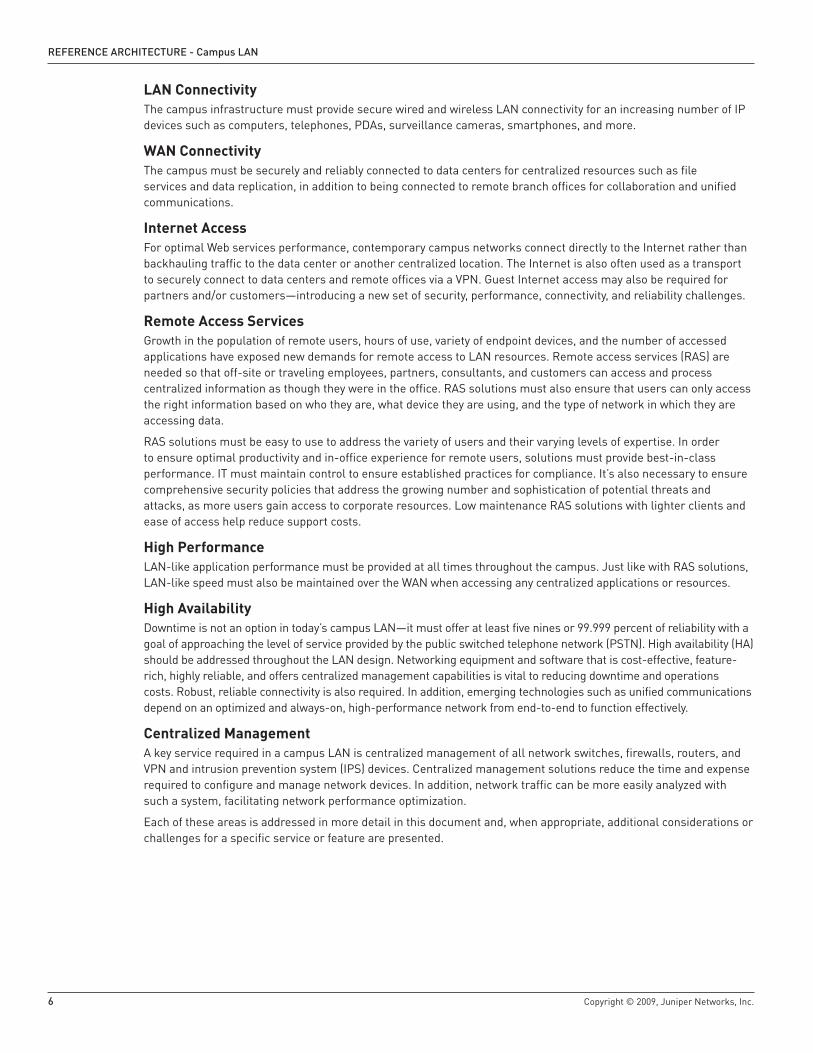
LAN ConnectivityThe campus infrastructure must provide secure wired and wireless LAN connectivity for an increasing number of IP devices such as computers, telephones, PDAs, surveillance cameras, smartphones, and more.
WAN ConnectivityThe campus must be securely and reliably connected to data centers for centralized resources such as file services and data replication, in addition to being connected to remote branch offices for collaboration and unified communications.
Internet AccessFor optimal Web services performance, contemporary campus networks connect directly to the Internet rather than backhauling traffic to the data center or another centralized location. The Internet is also often used as a transport to securely connect to data centers and remote offices via a VPN. Guest Internet access may also be required for partners and/or customers—introducing a new set of security, performance, connectivity, and reliability challenges.
Remote Access ServicesGrowth in the population of remote users, hours of use, variety of endpoint devices, and the number of accessed applications have exposed new demands for remote access to LAN resources. Remote access services (RAS) are needed so that off-site or traveling employees, partners, consultants, and customers can access and process centralized information as though they were in the office. RAS solutions must also ensure that users can only access the right information based on who they are, what device they are using, and the type of network in which they are accessing data.
RAS solutions must be easy to use to address the variety of users and their varying levels of expertise. In order to ensure optimal productivity and in-office experience for remote users, solutions must provide best-in-class performance. IT must maintain control to ensure established practices for compliance. It’s also necessary to ensure comprehensive security policies that address the growing number and sophistication of potential threats and attacks, as more users gain access to corporate resources. Low maintenance RAS solutions with lighter clients and ease of access help reduce support costs.
High Performance LAN-like application performance must be provided at all times throughout the campus. Just like with RAS solutions, LAN-like speed must also be maintained over the WAN when accessing any centralized applications or resources.
High AvailabilityDowntime is not an option in today’s campus LAN—it must offer at least five nines or 99.999 percent of reliability with a goal of approaching the level of service provided by the public switched telephone network (PSTN). High availability (HA) should be addressed throughout the LAN design. Networking equipment and software that is cost-effective, feature-rich, highly reliable, and offers centralized management capabilities is vital to reducing downtime and operations costs. Robust, reliable connectivity is also required. In addition, emerging technologies such as unified communications depend on an optimized and always-on, high-performance network from end-to-end to function effectively.
Centralized ManagementA key service required in a campus LAN is centralized management of all network switches, firewalls, routers, and VPN and intrusion prevention system (IPS) devices. Centralized management solutions reduce the time and expense required to configure and manage network devices. In addition, network traffic can be more easily analyzed with such a system, facilitating network performance optimization.
Each of these areas is addressed in more detail in this document and, when appropriate, additional considerations or challenges for a specific service or feature are presented.

Copyright © 2009, Juniper Networks, Inc. 7
RefeReNCe aRChiteCtuRe - Campus LaN
Campus LAN Design ConsiderationsA new campus LAN design is needed as legacy solutions cannot meet these key requirements, nor reduce costs and streamline operations. The new LAN design must also scale and accommodate emerging computing trends and additional network services without an entire redesign. The following section summarizes some of the trends and technical considerations for designing a modern campus network that addresses these requirements. These considerations are not necessarily specific to Juniper Networks solutions and may be applied universally to any campus network design, regardless of vendor.
Enterprise Computing TrendsIn addition to the services previously mentioned, the following trends must be considered in a campus LAN design:
The Proliferation of Unified CommunicationsThe adoption of unified communications including voice, video, and data services is on the rise. According to Forrester Research (2006), 46 percent of all companies in North America have installed IP telephony systems and 39 percent use VoIP to communicate with their remote users. Such deployments have a direct impact on the high performance and high availability requirements of a campus LAN. For example, not only must adequate LAN and WAN bandwidth be provisioned, but quality of service (QoS) rules must identify, classify, and prioritize traffic to deliver effective VoIP communication services.
Bandwidth-Hungry ApplicationsIn addition to the increased bandwidth needed for unified communications, many popular business applications such as Oracle, SAP, and PeopleSoft have introduced Web-enabled versions that require, in some instances, more than 10 times the bandwidth of their LAN-based counterparts, seriously impacting performance, reliability, and availability. Other activities, such as data backup to local servers, can also be bandwidth intensive; however, these activities can be scheduled to take place during times of low usage to lessen their impact on the network.
User ProductivitySince most business processes are now carried out online, the corporate LAN is a critical component of business growth and innovation. Because of that, any LAN downtime or inefficiency negatively impacts the corporate bottom line. Conversely, boosting network performance enhances business productivity, according to Information Week (2007). As such, the network must be leveraged with services such as wireless coverage and remote access to maximize productivity.
Increasing Focus on SecurityFBI/CSI statistics show that 72 percent of all companies surveyed reported at least one security incident in 2006. And there continues to be an ongoing proliferation of both internal and external attacks. Not surprisingly, a 2006 Forrester Research survey found that 57 percent of all firms consider “upgrading security environment” a top priority. As critical business processes become more distributed and unified communications present new vulnerabilities, the need for robust security is likely to intensify along with user access policies.
Demand for Wireless ServicesOne of the main drivers of better business decisions is access to key information and resources at all times. Employees of modern business go to meetings with their laptops in tow, expecting wireless access to all of their applications, data stores, resources, and services. Not only must wireless service be provided throughout the campus, but it should enable users to seamlessly move across the campus without service disruption, much like roaming cell coverage. Such wireless service enables users to access whatever materials are needed to support a presentation or budget forecast, or start a download from a centralized server and have it finished by the time they get to the conference room with their laptop, or to talk on a Wi-Fi phone throughout the campus.
Wireless service and access must always be secure. Different levels of wireless access must be provided for contractors, partners, and other guest users ensuring not only that the proper level of service is delivered but that access to appropriate resources is restricted.

8 Copyright © 2009, Juniper Networks, Inc.
RefeReNCe aRChiteCtuRe - Campus LaN
Server Centralization and Data Center ConsolidationA 2007 Forrester report states that 51 percent of all firms consider server centralization a key priority. Gartner (2007) also reports that most enterprise servers operate at 20 percent capacity. New technologies like virtualization are needed to better utilize these resources. At the same time, most campuses need local servers that require extra security, bandwidth optimization, and traffic prioritization.
To further reduce costs, simplify operations, and comply with regulatory guidelines, enterprises are also consolidating data centers. According to a 2006 Nemertes Research report, 91 percent of companies interviewed were under compliance constraints, and more than 50 percent of the companies had consolidated their dispersed data centers into fewer larger data centers in the recent 12 months, with even more planning to consolidate in the following 12 months.
In addition to high availability requirements ensuring non-stop operations, centralization raises new latency and security issues. Centralized management solutions that help reduce the time and resources devoted to keeping campuses online and operational are also needed.
Infrastructure SolutionsThe network infrastructure on today’s campus is no longer sufficient to satisfy these requirements. Instead of adding additional costly layers of legacy equipment and highly skilled IT resources to support the growing number of campus devices and services, enterprises need a new, more integrated and consolidated campus solution.
Juniper Networks delivers a proven IP infrastructure for the campus that meets these challenges, enabling the performance, scalability, flexibility, security, and intelligence needed to not just meet but increase campus user productivity. Juniper Networks offers flexible configurations and price points that meet the needs of all campuses, while delivering high-performance throughput with services such as firewall, adaptive detection and threat management, VPN, MPLS, IPV6, and Connectionless Network Services (CLNS).
figure 1: highly-available campus LaN configuration
SA Series
Access Point
VoIP
VoIP
VoIP
ISG Series
Steel-BeltedRadius
IC Series
EX4200 Series
EX8200 Series
EX8200 Series
EX8200 Series
M Series
M Series
EX4200 Series
EX4200 Series
EX3200 Series
INTERNET ANDPRIVATE WAN

Copyright © 2009, Juniper Networks, Inc. 9
RefeReNCe aRChiteCtuRe - Campus LaN
Campus Architecture OverviewLayered ApproachAn enterprise, campus LAN architecture may span up to three layers, from desktop devices connected to wiring closet switches at the access layer to the core layer at the center of a large campus LAN. The hierarchical topology segments the network into physical building blocks, simplifying operation and increasing availability. Each layer within the hierarchical infrastructure has a specific role.
figure �: the layered approach
The access layer provides an access control boundary and delivers network connectivity to end users in a campus.
The aggregation layer aggregates connections and traffic flows from multiple access-layer switches, providing a core enforcement perimeter as it delivers traffic to core-layer switches.
The core layer provides secure connectivity between aggregation-layer switches and the routers connecting to the WAN and the Internet, to enable business-to-business collaboration.
This document focuses primarily on how these layers are deployed in the campus infrastructure. Areas outside of that scope are presented when relevant to the discussion. For example, certain campus configurations may collapse one or more layers.
Benefits and Challenges to the Layered ApproachA multilayered architecture facilitates network configuration by providing a modular design that can rapidly and economically scale. It also creates a flexible network on which new services can be easily added without redesign. The layered approach also delivers separated traffic, balances load across devices, and simplifies troubleshooting.
This three-layered approach traditionally requires additional hardware and can be costly to configure, deploy, and administer for small campuses. To account for that, small campuses may collapse one or more layers.
Note: This document deals primarily with three-layered LAN designs, though it also introduces a two-layered design with a converged aggregation and core layer. Those supporting extremely small campuses may wish to view the Juniper Networks Branch LAN Design Guide for LAN designs that collapse multiple layers.
•
•
•
CAM
PUS
DAT
A CE
NTE
R
WAN(Multiple SPs)
CORE LAYER -10 GbE LAG
CORE LAYER -10 GbE
AGGREGATION LAYER -10 GbE Fiber
ACCESS LAYER - 10/100/1000BASE-T
Data Center Connectivity
Device Connectivity
AGGREGATION LAYER -GbE LAG Fiber
ACCESS LAYER -10/100/1000BASE-T

10 Copyright © 2009, Juniper Networks, Inc.
RefeReNCe aRChiteCtuRe - Campus LaN
Trying to address emerging bandwidth, throughput, and port density requirements, networks in the past have grown bloated with extra layers of inefficient, ill-suited legacy hardware that not only fail to meet these needs, but also add considerable management complexity, reduce network availability, and drive up capital and operational expenses.
A Network RevolutionA recent entrant into the evolving switching market, Juniper Networks has factored lessons learned and a breadth of experience into the development of a new portfolio of Ethernet switch products and network solution designs that address contemporary issues and accommodate future growth. These new products are designed to eliminate unnecessary network layers while providing a platform for delivering higher availability, converged communications, integrated security, and higher operational efficiency. With these solutions, Juniper Networks simultaneously advances the fundamentals and economics of networking by delivering greater value, increasing simplicity, and lowering the total cost of network ownership.
Access LayerOn a campus, the access layer provides network connectivity to end users by connecting devices such as PCs, printers, IP phones, and CCTV cameras to the corporate LAN via wired or wireless LAN (WLAN) access points. Access-layer switches typically reside in the wiring closets of each floor in each campus facility.
figure �: access layer at a highly available campus LaN
The access layer provides connectivity, Power over Ethernet (PoE), QoS, and security with policy services and network access control.
AGGREGATION LAYER
CORELAYER
L2/L3Switch
L2/L3Switch
L2/L3Switch
L2/L3Switch
L2Switch
L2Switch
ACCESS LAYER
INTERNET/PRIVATE WAN

Copyright © 2009, Juniper Networks, Inc. 11
RefeReNCe aRChiteCtuRe - Campus LaN
Access Layer Design ConsiderationsWired Port ConnectivityAccounting for an adequate number of wired ports for all computers, IP phones, CCTV cameras, wireless LAN access points, and other IP devices is the first step to addressing port requirements. The logical segmentation required and the number of logically separate networks that should share the same LAN must also be determined. Access layer switches must be scalable and provide HA features in addition to over-provisioned and underutilized Gigabit Ethernet or 10-Gigabit Ethernet uplinks to aggregation layer switches. These considerations help establish what type of hardware configuration is needed.
WLAN ConnectivityIdeal for employees meeting in dispersed conference rooms or areas other than their offices, as well as a necessity for supporting contractors, partners, and guests, wireless access must be provided across the campus. With the plethora of IP devices currently available on the market and used in the workplace, especially by unknown guests, a comprehensive security policy must ensure that only trusted devices access the campus network. Further, the appropriate LAN resources must be restricted and made available only to those with the proper credentials—especially true for contractors, partners, and other guests. Seamless coverage enabling a user to roam the campus with the same login credentials is also expected.
There are two main designs for flexible and roaming wireless solutions:
figure 4: flexible and roaming wireless access solutions
Non-controller-based wireless access
In this design, an 802.1Q trunk for access point to switch is required. Roaming requires spanning at least two virtual LANs (VLANs) between access layer switches.
Controller-based wireless access
This design uses a virtualized, centralized wireless controller. Access point VLANs are placed local to the access switch. Roaming does not require spanning VLANs across the campus network.
•
•
AGGREGATION
ACCESS
TO CORE
Wireless Controller
Wireless VLANs
L2/L3Switch
L2/L3Switch
Wireless OAC Wireless OAC
L2/L3Switch
L2/L3Switch
Access Point Access Point

1� Copyright © 2009, Juniper Networks, Inc.
RefeReNCe aRChiteCtuRe - Campus LaN
PoENearly all campuses have IP phones today, most of which require PoE to function. Campus facilities are likely to also have PoE security cameras and WLAN devices. Accounting for the correct number of PoE ports is vital, as the system configuration depends on it. Some access equipment doesn’t provide PoE services, so it’s important to use traditional wall-powered IP phones, CCTV cameras, and WLAN access points in those installations. In addition to accounting for the number of PoE ports, it is important to determine the level of power needed for the devices connected to each port. Many devices requiring PoE will use up to 15.4 watts, the maximum allowed for class 3 PoE. However, there are some devices such as security cameras with advanced pan, tilt, and zoom functions, and Institute of Electrical and Electronics Engineers (IEEE) 802,11n WLAN access points that may need more than 15.4 watts of PoE.
VLAN and Spanning Tree ProtocolCampus LANs use VLANs to logically group sets of users, devices, or data—regardless of location—into logical networks through software configuration instead of physically relocating devices on the LAN. VLANs help address issues such as scalability, security, and network management.
VLANs are in essence Layer 2 broadcast domains that exist only within a defined set of switches. Using the IEEE 802.1Q standard as an encapsulation protocol, packets are marked with a unique VLAN tag. Tagged packets are only forwarded or flooded to stations in the same VLAN. To reach any station not belonging to the same VLAN, tagged packets must be forwarded through a routing device. Any switch or switch port can be dynamically or statically grouped into a VLAN. Alternately, traffic may be grouped into a VLAN and forwarded through specific ports based on the specific data protocol being sent over the LAN. For example, VoIP traffic from a softphone can be segmented from other traffic and put into a VLAN that gets a higher quality of service.
1. Spanning Tree Protocol (STP) VLANs may create multiple active paths between network nodes, resulting in problematic bridge loops. Since the same Media Access Control (MAC) addresses are seen on multiple ports, the switch forwarding table can fail. Also, broadcast packets may end up being forwarded in an endless loop between switches, consuming all available bandwidth and CPU resources. STP, the IEEE 802.1D standard, ensures a loop free topology for any bridged LAN. STP is designed to leave a single active path between any two network nodes by first creating a tree within a mesh network of connected LAN switches, and then disabling the links which are not part of that tree. STP thus allows a network design to include redundant links to provide automatic backup paths if an active link fails, without the danger of bridge loops or the need for manual enabling/disabling of these backup links. Each VLAN can run a separate instance of Spanning Tree Protocol.
2. Issues with STP Troubleshooting may be challenging with STP due to complicated routing, incorrect configuration, or improper cabling. Since every packet must go through the root bridge of the spanning tree, routing performance with STP can also be suboptimal. STP often creates underutilized links and lacks a load-balancing mechanism as well. In addition, STP has a slow convergence of up to 30 to 50 seconds after a topology change. To combat this, Rapid Spanning Tree Protocol (RSTP) was created, providing sub-second convergence. Multiple Spanning Tree Protocol (MSTP), the 802.1s standard, supports multiple instances of STP, but it also increases configuration complexity.

Copyright © 2009, Juniper Networks, Inc. 1�
RefeReNCe aRChiteCtuRe - Campus LaN
Using Layer 2 versus Layer 3 at the Access LayerAccess switches are configured to use Layer 2 or Layer 3.
figure 5: Layer � versus layer � at access layer
1. Using Layer 2 at the access layer
Using Layer 2 at the access layer is the traditional configuration. This provides plug-and-play configuration and makes the deployment in smaller networks easier to implement and manage.
There are a number of challenges associated with this option. This configuration usually requires STP, resulting in multiple connections, one active and one redundant. The demarcations from L2 and L3 with OSPF add multiple fault isolation domains, which add extra complexity in configuring and managing the network. Troubleshooting can also be more difficult in such configurations. In addition, convergence in case of a switch or link failure often takes too long to ensure a highly available campus LAN.
2. Using Layer 3 at the access layer
Routing is enabled on the switch when using Layer 3 at the access layer, but it still provides the capability to put users into different VLANs. Layer 3 is more deterministic. No Layer 2 loops are created in this design. Layer 3 should be configured in the uplinks from the access switch to the aggregation layers, with Layer 2 configured at the access switch to the devices. STP can be enabled to prevent inadvertent loops. Or STP can be disabled and bridge protocol data unit (BPDU) protection enabled, making it easier to troubleshoot. When STP is disabled, OSPF or other open-standard protocols can be used to provide sub-second convergence. For larger or more complex networks, this is a low-maintenance solution in comparison to using Layer 2 at the access layer.
This option is more costly to deploy with legacy network equipment, as Layer 3 usually requires an additional license fee.
3. Recommendation
Unlike competitive products, Juniper Networks solutions provide the ability to deliver either Layer 2 or Layer 3 at the access layer without any added expense—Layer 3 features are built into the base Juniper Networks JUNOS® Software license with no extra license fees required. Instead of STP, Juniper Networks solutions also use open-standard protocols such as OSPF with equal-cost multipath (ECMP) for rapid convergence. A LAN design using the Juniper Networks EX4200 Ethernet Switch with Virtual Chassis technology also benefit from Redundant Trunk Group (RTG) protocol as a built-in, optimized replacement to STP for sub-second convergence and automatic, high-performance load balancing. And, according to an independent 2007 Lake Partners study, operating expense with Juniper Networks solutions can be up to 29 percent lower than competitive solutions. Juniper’s switches with Virtual Chassis technology provide simplified device management as well, equating to lower CapEx and OpEx compared to competing solutions.
LAYER 3
LAYER 2
LAYER 3
LAYER 2
WAN Edge
Aggregation Layer
Access Layer
Layer 2 at Access Layer 3 at Access

14 Copyright © 2009, Juniper Networks, Inc.
RefeReNCe aRChiteCtuRe - Campus LaN
Considerations for Implementing Unified CommunicationsDelivering voice, video, and data on a single network infrastructure offers many cost savings and operational simplicity benefits. It lowers communications expense and decreases the overall cost of network ownership. It also simplifies network administration and maintenance operations. However, it also presents a number of network challenges including QoS, security, and port-configuration requirements.
Unified communications have real-time requirements that are not necessary for most data applications. VoIP packets, for example, must be efficiently transported throughout the LAN and WAN to ensure high-quality voice communications, even when the network is experiencing high utilization or congestion. Simply adding more LAN or WAN bandwidth doesn’t make the network voice-friendly. Latency, jitter, and packet loss are common VoIP challenges that must be accounted for with QoS queuing and scheduling to ensure high-quality VoIP communications. In addition to access-based security measures, addressing port density and PoE requirements for IP phones are fundamental to a successful design.
1. QoS
Access layer devices must be able to identify, classify, and queue traffic across the LAN to ensure optimal performance or QoS. Once identified, traffic is properly assigned and managed to ensure that each application, such as unified communications, delivers satisfactory performance across the entire LAN.
a. Classification and Enforcement
Each type of data flow on the LAN has different QoS requirements. Traditional applications such as Web browsing and email work fine with the best-effort delivery standard on IP networks. However, additional requirements must be met to ensure effective delivery of voice, video conferencing, and other real-time applications. Unlike streaming video, for example, real-time voice data can’t be cached nor have lost packets retransmitted, since both would add an unacceptable delay and ruin the quality of the communication, resulting in a poor customer experience. Voice packets, therefore, must be given top priority when creating QoS policies.
IP phones and other communication devices are likely to be spread throughout the LAN in many different physical locations. VLANs, as discussed earlier, can be used to identify and segment voice, video conferencing, and data traffic, regardless of location, into logical VLANs so that the appropriate QoS parameters can be easily applied to maintain optimal service for each data flow.
To facilitate QoS, data can be classified by a combination of MAC address, IP address, physical port, and protocol. For example, a block of IP phones connected to a specific LAN segment could be placed in a VLAN designated for voice traffic based on its port numbers. Or Link Layer Detection Protocol-Media Endpoint (LLDP-MED) may be used to discover an IP phone and automatically place it on a VLAN. Or traffic from a softphone can be analyzed at the protocol level, with voice data given top priority regardless of the source port. Once the data is classified with the appropriate Differentiated Services code point (DSCP), it needs to be queued and scheduled. Most importantly, the same QoS rules need to be enforced consistently throughout the LAN and WAN.
b. Built-in QoS
QoS or class of service (CoS) features are built into all Juniper Networks infrastructure, security, and application acceleration solutions. All Juniper Networks switches and routers run JUNOS, which comes standard with a full complement of QoS services. Juniper Networks EX Series Ethernet Switches, for example, support eight (8) hardware queues per port and offer a range of policing options from best-effort delivery to enhanced delivery to assured delivery. Since the same JUNOS Software is found across all Juniper Networks router and switch solutions, the same QoS policies can be used throughout the LAN and WAN design for easy and consistent traffic management. In addition, application-specific integrated circuits (ASICs) in all of Juniper’s solutions support QoS by processing prioritized data and minimizing CPU load.
2. Security
Implementing unified communications on the data network increases security concerns that can have serious service impacts. Malicious attacks from outside the network and inadvertent attacks from within the network must be prevented. New ways of toll fraud and new security risks like eavesdropping are being discovered at an ever-increasing rate. Additional points of entry are created and a hacked VoIP system now provides a back door to the corporate LAN. Security risks range from viruses, worms, and DoS attacks to unauthorized access. Deployment of VoIP solutions, similar to other network appliances, must account for security of the device itself as well as how

Copyright © 2009, Juniper Networks, Inc. 15
RefeReNCe aRChiteCtuRe - Campus LaN
it can be used to attack the network as a whole. Juniper Networks IDP Series Intrusion Detection and Prevention Appliances are recommended to thwart VoIP-related attacks in addition to typical intrusions. An 802.1X solution should be used to authenticate and manage endpoints via policy-based access. Using the protocol-specific application-level gateway (ALG) features on all firewalls is recommended to dynamically open and close ports for each VoIP call.
Threat ContainmentIt’s vital that the access layer include integrated security features to guard against intruders or other external threats such as distributed denial of service (DDoS) attacks. It should deliver an extra layer of security by first authenticating users and performing virus checks, then enforcing precise, end-to-end security policies that determine who can access what network resources, as well as QoS policies to ensure delivery of business processes.
Modular Chassis TechnologyA campus LAN must be able to quickly and seamlessly accommodate growth and new technologies. This needs to be done economically from capital expense, network overhead, and network operational expense perspectives. This is often addressed at the access layer via modular chassis solutions.
Ideal modular solutions should offer high-density, high-speed ports with optional, cost-effective PoE capabilities. Each modular chassis should also offer high-speed uplink connections and provide the same type of HA features found in traditional chassis-based solutions. The ideal modular chassis solutions should also provide the capability to configure and manage more than one switch as a single “Virtual Chassis” configuration dramatically reducing both capital and operating expense while providing additional HA features.
Access Layer SolutionsScalable Access Solutions with Virtual Chassis TechnologyJuniper Networks provides scalable access solutions with true innovation: EX4200 switches with Virtual Chassis technology. This solution advances the economics of networking by delivering the high availability and high port densities of a modular chassis in a compact, cost-effective, pay-as-you-grow platform.
1. Features and Benefits
Each compact EX4200 switch offers either 24 100BASE-FX/1000BASE-X ports, 24 10/100/1000BASE-T ports, or 48 10/100/1000BASE-T ports. The 10/100/1000BASE-T platforms offer either full or partial PoE options (partial solutions provide PoE on the first eight ports of the switch; full options provide PoE on all 24 or 48 ports). Each PoE port delivers up to 15.4 watts of power and is compatible with class 0-3 IP phones. The EX4200 switches’ built in LLDEP-MED services help automate and extend the power management of these PoE endpoints, as well as assist with inventory management and directories.
Each EX4200 switch supports optional front-panel uplink modules supporting either four Gigabit Ethernet or two 10-Gigabit Ethernet ports for high-speed connections to aggregation or core switches. These uplinks support online insertion and removal.
figure 6: Virtual Chassis technology
Legacy Switch:12-15 Rack Units (RUs)
48-288 GbE ports + 4 10GbE
EX4200 Switch1 RU
48 GbE - 2 10GbE
EX4200 Switches2 RU
96 GbE + 4 10GbE
EX4200 Switches4 RU
192 GbE + 8 10GbE

16 Copyright © 2009, Juniper Networks, Inc.
RefeReNCe aRChiteCtuRe - Campus LaN
2. Pay-As-You-Grow Scalability
The Juniper Networks Virtual Chassis technology enables a campus to add as many EX4200 switches as needed to meet its connectivity needs. Juniper Networks’ unique pay-as-you-grow model allows a campus to start with a single EX4200 switch (1 RU) and incrementally add up to nine more switches to the Virtual Chassis configuration at any time—for a total of 10 switches—before starting another Virtual Chassis. Resiliently interconnected via a 128 Gbps virtual backplane, Gigabit Ethernet, or 10-Gigabit Ethernet uplink module, a fully-loaded Virtual Chassis configuration supports up to 240 100BASE-FX/1000BASE-X ports, 480 10/100/1000BASE-T ports, or any combination of the two, plus up to 20 10-Gigabit Ethernet uplink ports or 40-Gigabit Ethernet uplink ports, or any combination of the two.
Not only does Virtual Chassis technology lower capital expenses when compared to traditional chassis systems, it also dramatically reduces operating expenses by enabling any group of interconnected switches to appear on the network and be remotely managed as a single unit. Coupled with the incremental, pay-as-you-grow model, the compact form factor of the EX4200 switches enables the campus to save not only on upfront and recurring rack space usage but also on costly power and cooling fees.
Small campuses on a budget may consider the Juniper Networks EX3200 Ethernet Switch, which provides most of the same robust features as the EX4200 with the exception of Virtual Chassis technology.
3. Carrier-class Reliability
The EX4200 switches with Virtual Chassis technology also provide the same HA features as modular chassis-based systems. Each switch supports redundant, load-sharing, hot-swappable AC or DC power supplies, as well as a field-replaceable hot-swappable fan tray with redundant blowers, any of which can fail without affecting operations.
Virtual Chassis technology provides unparalleled device and link HA utilizing the virtual backplane protocol and JUNOS Software. Each set of interconnected switches with Virtual Chassis technology automatically takes full advantage of the multiple Routing Engines present to deliver graceful Routing Engine switchover (GRES) and non-stop forwarding to ensure uninterrupted operation in the rare event of any individual switch failure. For added device and link HA, a Virtual Chassis configuration can be deployed to address any requirements. For example, a single Virtual Chassis configuration of 10 switches could instead be configured as two five-switch Virtual Chassis configurations, or in any other desired combination.
4. Location Independence
Another key feature of Virtual Chassis technology is that the virtual backplane protocol can also be extended across the optional Gigabit Ethernet or 10-Gigabit Ethernet uplink ports to interconnect switches that are more than a few meters apart; creating a single virtual switch that spans multiple wiring closets, floors, server racks, or buildings. Even when separated by long distances, interconnected switches with Virtual Chassis technology can be managed, monitored, upgraded, and otherwise treated as a single resilient switch—dramatically reducing recurring management and maintenance costs.

Copyright © 2009, Juniper Networks, Inc. 17
RefeReNCe aRChiteCtuRe - Campus LaN
figure 7: Reducing Capex and Opex with Virtual Chassis technology
VoIP
VirtualChassis
VoIP
VirtualChassis
VoIP
VirtualChassis
VoIP
Virtual Chassis
VirtualChassis
L2/L3 Switch
L2/L3 Switch
L2/L3 Switch
L2/L3 Switch
50% fewerwiring closets
to manage
WEST CLOSET
Standalone or Stackable Deployment
Deployment with EX Series Virtual Chassis Technology
WEST CLOSET
WEST CLOSET WEST CLOSET
FLOOR
FLOOR 1
FLOOR
FLOOR 1
Virtual Chassis

18 Copyright © 2009, Juniper Networks, Inc.
RefeReNCe aRChiteCtuRe - Campus LaN
5. Reducing CapEx and OpEx
At one-sixth the footprint and less than one-third the cost of the most commonly purchased chassis-based switch offering 48 fiber Gigabit Ethernet ports and four 10-Gigabit Ethernet wire-speed ports, the EX4200 with Virtual Chassis technology represents the new generation of switching.
The EX4200 switches come standard with features that are costly add-ons in competitive solutions. For example, the EX4200 includes L3 in the base platform, offers built-in 10-Gigabit Ethernet uplink capability, delivers partial or full PoE, provides built-in redundant power supplies and more in a single cost-optimized platform. OpEx savings include the unified JUNOS feature set and remote mirroring capability for full troubleshooting from a central network operations center (NOC) rather than having to send IT staff onsite for maintenance, upgrades, and debugging.
Not only does Juniper Networks lower capital and operational expense by collapsing layers and therefore reducing the number of devices in the network that need to be purchased and managed, but Virtual Chassis technology saves on valuable rack space, as well as recurring power and cooling costs. Delivering greater value while reducing capital and operational expenses, Virtual Chassis technology frees up precious IT budget dollars that can be invested in new technologies that improve business productivity.
Note: For a full set of features, benefits, and specifications, please view the Juniper Networks EX4200 with Virtual Chassis Technology data sheet.
Wireless SolutionsSecure WLAN solutions from Juniper’s partners Aruba Networks, Trapeze Networks, and Meru Networks are recommended for campuses that wish to provide wireless service. Each solution integrates seamlessly with the Juniper Networks Odyssey Access Client, an enterprise-class 802.1X software access client. Working with an 802.1X-compatible RADIUS server such as Juniper Networks Odyssey Access Server or Steel-Belted Radius Servers, OAC secures the authentication and connection of WLAN users, ensuring that only authorized users can connect, that login credentials will not be compromised, and that data privacy will be maintained over the wireless link. A specialized version of OAC includes a cryptographic module that has been Federal Information Processing Standards (FIPS) 140-2 level 1 validated to meet security requirements of government agencies. OAC is also an ideal client for enterprises that are deploying identity-based (wired 802.1X) networking—saving time and effort by permitting one-time deployment of wireless and wired 802.1X access while also simplifying the user experience and reducing training costs.

Copyright © 2009, Juniper Networks, Inc. 19
RefeReNCe aRChiteCtuRe - Campus LaN
Aggregation LayerThe aggregation layer, sometimes referred to as the distribution layer, aggregates connections and traffic flows from multiple access layer switches to provide high-density connectivity to the LAN core.
figure 8: aggregation layer in a highly available campus LaN
Due to their location in the network, aggregation-layer switches must provide scalability, high-density wire-rate ports, and HA hardware and software features that deliver carrier-class reliability and robustness. Multiple Gigabit Ethernet downlinks from the access wiring closet are needed for redundancy. In addition, multiple 10-Gigabit Ethernet uplinks to the core are required.
Multiple aggregation layer switches, delivering wire-rate performance for deterministic operation, are used for redundancy. They should run Layer 3 for route summarization, fast convergence and load sharing, and redundant paths.
Aggregation Layer Design ConsiderationsSegmentation/VirtualizationAggregation switches should also support generic routing encapsulation (GRE) tunneling for sending mirrored traffic from remote locations to monitoring devices in the network operations center for centralized troubleshooting and analysis, or to build segregated overlay networks without the challenges associated with Spanning Tree.
CORELAYER
L2/L3Switch
L2/L3Switch
L2/L3Switch
L2/L3Switch
L2Switch
L2Switch
ACCESS LAYER
AGGREGATION LAYER
INTERNET/PRIVATE WAN

�0 Copyright © 2009, Juniper Networks, Inc.
RefeReNCe aRChiteCtuRe - Campus LaN
Aggregation Layer SolutionsScalable Aggregation Layer SolutionsDue to the performance requirements of a highly available campus, HA features and scalability are increased with a LAN design including an aggregation layer. The EX4200 or Juniper Networks EX8200 line of Ethernet switches both provide the performance and services needed at the aggregation layer.
1. HA
Virtual Chassis technology enables fail-safe operations. Similar to chassis-based systems, a Virtual Chassis configuration has route engine redundancy, which means that a master Routing Engine and backup Routing Engine maintain forwarding information in the event of a master failure. Redundant links to each WAN edge device are also provided in the event of a device or link failure. In addition to the HA features standard in the EX4200 switches, all equipment runs JUNOS, providing software HA features such as QoS and GRES, preserving forwarding and routing operations during device events with non-stop forwarding and automatic load balancing.
2. Scalable Performance
Each EX4200 switch with Virtual Chassis technology provides pay-as-you-grow scalability with features such as no (fiber only), full or partial PoE capability (8/24 or 8/48 ports). Virtual Chassis technology enables seamless scaling by allowing up to 10 EX4200 switches to be interconnected via a 128 Gbps backplane or via optional Gigabit Ethernet or 10-Gigabit Ethernet uplink modules. Virtual Chassis technology simplifies administration as these devices can be managed as one unit. In addition, multiple 10-Gigabit Ethernet uplinks from any of the switches that are members of the same Virtual Chassis configuration (up to 10 EX4200 switches), regardless of physical location, can be link-aggregated for higher bandwidth connections to other aggregation or core switches.
If more ports or throughput is required, another Virtual Chassis configuration of up to 10 EX4200 switches can be created. If extra device and link redundancy is required, as many EX4200 switches as desired can be deployed.
To meet the aggregation demands of even the largest campus, the EX8200 line of terabit-chassis switches deliver a powerful, high-density, high-performance solution. Capable of up to 3.2 Tbps throughput, the EX8200 offers up to 64 (eight-slot chassis) or 128 (16-slot chassis) wire-speed 10-Gigabit Ethernet ports.
3. CapEx and OpEx Savings
Typically more than two layers of legacy Layer 3 switches are required to achieve the wire-speed port densities demanded by today’s high-performance campus. The EX4200 switches, however, meet these needs and also enable the collapse of the LAN core and aggregation layers, creating a direct positive impact on the economics of networking. Virtual Chassis technology also simplifies network operations and lowers operating expense on all fronts, from JUNOS upgrades and moves, adds and changes, to troubleshooting and problem resolution.
Previously, only expensive chassis-based switches could provide the combination of high 1000BASE-X fiber port densities and the HA features required to satisfy aggregation layer requirements. While certainly scalable and highly available, these modular chassis-based switches are not a very cost-effective solution for such applications. First, they require a considerable up-front investment for the chassis and common equipment, even if not fully populated. Second, because of their size, modular chassis require more space in already crowded racks, taking up valuable real estate. Third, modular chassis require more power and cooling—recurring costs that increase operational expenses and contribute to the production of greenhouse gasses that threaten the environment.
The EX4200 switches with Virtual Chassis technology represent the new generation of aggregation switching. They deliver greater value while reducing capital and operating expenses, freeing up valuable IT resources to invest in new technologies to improve business productivity.
Note: For a full set of features, benefits, and specifications, please view the Juniper Networks EX4200 switches with Virtual Chassis Technology data sheet.

Copyright © 2009, Juniper Networks, Inc. �1
RefeReNCe aRChiteCtuRe - Campus LaN
Core LayerThe core layer provides a fabric for high-speed packet switching between multiple aggregation devices or the access layer in a collapsed network. It serves as the gateway where all other modules meet, such as the WAN Edge.
figure 9: Core layer in a highly available campus LaN
Core Layer ConsiderationsHigh-density throughput and HA features are the main core considerations. The core typically requires a 10-Gigabit Ethernet interface for high throughput and wire-rate performance. Core layer switches should also offer redundant control plane, power, and cooling components for device redundancy. The design should include multiple core layer switches as system redundancy for network redundancy and optimal convergence.
Core Layer SolutionsHigh Performance Core Layer SolutionsDue to its high availability and high-performance features, the EX8200 line of Ethernet switches are recommended as a core layer switch solution.
1. High Availability
The EX8200 line offers a fail-safe core layer solution. Redundant links to each core layer device are provided in the event of a device or link failure. Redundant Routing Engines and switch fabrics as well as redundant power supplies and fans are offered. All equipment runs JUNOS, providing HA features such as QoS and GRES that preserve forwarding and routing operations during device events with non-stop forwarding and automatic load balancing.
2. Scalable Performance
The EX8200 line of terabit-chassis switches deliver a powerful, high-density, high-performance solution. Capable of up to 3.2 Tbps throughput, the EX8200 line offers up to 64 (eight-slot chassis) or 128 (16-slot chassis) wire-speed 10-Gigabit Ethernet ports. The EX8200 line today delivers up to 80 Gbps of switching capacity per slot. By providing capacity now, the EX8200 line allows users to easily migrate to higher speed connections when they are
CORELAYER
L2/L3Switch
L2/L3Switch
L2/L3Switch
L2/L3Switch
L2Switch
L2Switch
ACCESS LAYER
AGGREGATION LAYER
INTERNET/PRIVATE WAN

�� Copyright © 2009, Juniper Networks, Inc.
RefeReNCe aRChiteCtuRe - Campus LaN
ready—without requiring any changes to the switch fabric, Routing Engines, power supplies, or cooling system. The EX8200 line also offers a redundant control plane and runs Juniper Networks operating system—JUNOS Software—for maximum software HA.
3. CapEx and OpEx Savings
Typically, more than two layers of legacy Layer 3 switches are required at the core to achieve the wire-speed port densities demanded by today’s high-performance campus. Enabling the collapse of a number of core layers, the high-density, high-performance EX8200 line of Ethernet switches create a direct positive impact on the economics of networking. The solution also lowers operating expense and simplifies all network operations via JUNOS.
Delivering greater value while reducing capital and operating expenses, the EX8200 line frees up valuable IT resources that may be redirected toward new technologies to improve business productivity and further streamline operations.
Note: For a full set of features, benefits, and specifications, please view the Juniper Networks EX Series Ethernet Switches data sheets.
Is the Core Layer Essential?As it’s possible to mesh the aggregation layer in a two layer network, not all feel the core layer is essential in a campus LAN.
figure 10: Benefits of the core layer
Challenges and BenefitsTypically, more than two layers of legacy Layer 3 switches are required to achieve the wire-speed port densities demanded by today’s high-performance enterprises. While meshing aggregation switches is possible, each aggregation switch requires N-1 meshed links, where N equals the number of aggregation groups. This design is hard to manage and scales poorly, wasting valuable ports in each group when additional aggregation switches are added. Previously, only expensive chassis-based switches could provide the combination of high 1000BASE-X fiber port densities and the HA features required to satisfy aggregation requirements. While certainly scalable and highly available, these modular chassis-based switches are not a very cost-effective solution for such applications. First, they require a considerable up-front investment for the chassis and common equipment, even if not fully populated. Second, because of their size, modular chassis require more space in already crowded server racks, taking up valuable real estate. Third, modular chassis require more power and cooling—recurring costs that increase capital expenses and contribute to the production of greenhouse gasses that threaten the environment.
A dedicated core layer offers dual-homed aggregation to the core. This simplifies scaling and provides OSPF ECMP for load sharing, redundant links.
L2/L3Switch
L2/L3Switch
L2/L3Switch
L2/L3Switch
L2/L3Switch
L2/L3Switch
L2/L3Switch
L2/L3Switch
L2/L3Switch
L2/L3Switch
AGGREGATION
CONVERGED COREWITHOUT CORE
Simplified core design with dual-homedaggregation switches
Each switch requires N links, where N = number of switches in layer
AGGREGATION
CORE

Copyright © 2009, Juniper Networks, Inc. ��
RefeReNCe aRChiteCtuRe - Campus LaN
Consolidating the Core and Aggregation LayersMost core switches, designed for an earlier time when Gigabit Ethernet was the newest and fastest technology, deliver a limited number of 10-Gigabit Ethernet ports to support high-performance, high-speed uplinks from aggregation switches deployed throughout the campus. While the limited port densities offered on these devices may have been sufficient at some point, constant network expansion means that they have long outgrown their efficacy.
In order to scale efficiently and provide the 10-Gigabit Ethernet port densities needed in today’s LAN core, these legacy switches must be deployed in multiple layers within the core. While ultimately effective, this approach requires an extra layer of core switches. Not only does it add tremendously to capital expenses by consuming a large chunk of the IT budget, it also complicates operations, adding an additional maintenance and management burden, increasing network latency, and creating unwanted oversubscription ratios that reduce overall application performance.
figure 11: Core layer collapsed into the aggregation layer
1. Features and Benefits
The EX8200 line of terabit-chassis switches advance the economics of networking in two ways. First, the EX8200 line delivers the needed 10-Gigabit Ethernet wire-rate port density in the core, eliminating the need to deploy multiple layers of switches that add complexity, cost, oversubscription, and latency. Second, the 10-Gigabit Ethernet port density is sufficient to eliminate the aggregation layer entirely for medium-sized enterprise networks, enabling the access switches to connect directly to the core over wire-speed 10-Gigabit Ethernet links. Eliminating a full layer of aggregation switches dramatically reduces capital expenses and simplifies network operations—everything from OS upgrades and moves, adds and changes, to troubleshooting and problem resolution.
For large enterprise networks that require an aggregation layer, Juniper Networks extends those CapEx reductions to the aggregation layer. Aggregation switches, which consolidate distributed wiring closets on a single platform and connect them to core switches, require high-density fiber interfaces to support potentially long runs between floors or even buildings. Due to their critical role of providing connectivity between distributed users and centralized servers in the corporate network, aggregation switches also require HA features to ensure continuous delivery of applications and business processes.
INTERNET/PRIVATE WAN
EX3200 EX3200EX3200
EX8200Line
EX8200Line

�4 Copyright © 2009, Juniper Networks, Inc.
RefeReNCe aRChiteCtuRe - Campus LaN
WAN Edge IntegrationWAN connectivity provides a vital link from the campus to centralized services and resources. Designing and scaling a campus LAN for assured network connectivity and performance is a challenge that every high-performance organization faces.
figure 1�: WaN edge in a highly available campus LaN
WAN Edge ConsiderationsConnectivityA WAN edge routing platform must offer sufficient high-speed Ethernet ports to provide connectivity between the WAN and the core or aggregation layer. It also must provide high-performance throughput to the Internet and WAN.
HAAll WAN edge devices must provide a full complement of HA services to maintain critical WAN connectivity. The hardware must be robust and offer redundant power supplies and cooling fans. Devices should be paired in active/active routing states for optimal HA. And an alternate connection to the Internet or WAN must be maintained.
Voice GatewaySecure and optimized voice services should be provided at the WAN edge to enable effective communications across the LAN and WAN. Either an integrated or standalone VoIP gateway may be implemented.
WAN AccelerationAdding more bandwidth doesn’t automatically deliver LAN-like performance across the WAN. Acceleration services are needed to optimize performance of centralized applications across the WAN at all times, even when bandwidth is constrained.
CORELAYER
WAN EDGE
L2/L3Switch
L2/L3Switch
L2/L3Switch
L2/L3Switch
M Series M Series
L2Switch
L2Switch
ACCESS LAYER
AGGREGATION LAYER
INTERNET/PRIVATE WAN

Copyright © 2009, Juniper Networks, Inc. �5
RefeReNCe aRChiteCtuRe - Campus LaN
Firewall/VPNSecurity must be provided at the WAN edge, including VPN connections to remote locations and users as well as integrated firewall services to protect against worms, trojans, viruses, and other malware. Such services should be centrally managed to facilitate rapid deployment and minimize ongoing operational costs.
WAN Edge SolutionsA WAN edge routing platform must offer sufficient high-speed Ethernet ports to provide connectivity between the WAN and the aggregation or access layer. The Juniper Networks M Series Multiservice Edge Routers meet these requirements and more. The platform runs JUNOS, providing advanced carrier-class and field-proven routing features that include QoS, and it also offers firewall and VPN services for securing WAN traffic.
M Series Routing PlatformThe M Series provides predictably high performance and a modular, carrier-class interface that delivers secure, reliable, and scalable network connectivity.
1. Features and Benefits
Capable of throughput up to 320 Gbps, the M Series multiservice edge router offers a full breadth of connectivity options from DSO to OC-192/STM-64, and from 100 Mb to 10-Gigabit Ethernet. The platform also runs JUNOS, providing advanced carrier-class and field-proven routing features that include advanced services such as MPLS, IPv6, and multicast in the base system at no additional license fee or upgrade.
2. HA
The M Series delivers carrier-class HA with fully redundant hardware, including redundant Routing Engines and Switching/ Forwarding Engine Boards. JUNOS Software provides additional HA features.
3. Integrated Services
M Series routers provide the essential security functions required for securely connecting sites over the Internet, including integrated firewall and IPsec VPN. The platform also supports centralized user security policy and enables a unique high availability option in the form of dynamic route-based VPNs. Virtualization technologies allow segmentation of the network into many separate zones within a single platform for enforcing compliance to corporate security policies.
Built-in QoS improves bandwidth utilization and unified communications performance. It also minimizes latency, jitter, and packet loss to ensure voice and data performance.
In addition to a command-line interface (CLI), J-Web—built into JUNOS Software—offers remote Web-based management of all M Series models. Built-in troubleshooting also minimizes network downtime and decreases operating expenses and revenue losses due to outages.
The M Series consolidates multiple services into a single platform, providing the lowest possible CapEx. The rich feature set allows customers to try many different services without capital expenditure and scale successful services to larger populations.
For smaller campuses, the Juniper Networks J Series Services Routers may be utilized. Or, should security be the primary focus at the WAN edge, Juniper Networks SSG Series Secure Services Gateways could also be considered.
Note: For a full set of features, benefits, and specifications, please see the Juniper Networks M Series Services Routers data sheet.

�6 Copyright © 2009, Juniper Networks, Inc.
RefeReNCe aRChiteCtuRe - Campus LaN
High Availability in the Campus NetworkAs stressed throughout this document, it’s crucial that the campus network strive to operate with the same reliability and uptime as the PSTN network. Downtime is just not an option to remain competitive in any industry in today’s marketplace.
Device-Level HAMost device failures are due to power supply failures or mechanical cooling problems. It is important to always support business processes with high-quality, carrier-class network devices such as the EX Series and MX Series platforms. Purchasing equipment with dual power supplies and redundant fans or blowers to minimize equipment failure is always recommended, and raises the mean time to repair (MTTR). Additional device-level HA can be provided by doubling up on key devices to ensure that there is a backup device to pick up in the event of a failed device. If neither budget nor configuration supports a full set of backup devices, purchasing extra key device components, such as a backup set of field-serviceable or hot-swappable power supplies or fans, helps mitigate the impact of a device failure.
Link-Level HAEnsuring that business processes maintain vital data flow through internal and external resources is provided through link-level HA. At the campus, link-level HA requires that two links operate in an active/backup configuration, such that if one link fails, the other can take over or reinstate the forwarding of traffic that had been previously forwarded over the failed link.
Redundant Links: Square versus TriangleA square or triangle link configuration can be used to provide redundant paths between devices.
figure 1�: Dual homing—square versus triangle
1.Peering Square Configuration
In this design, a Layer 3 peering square is configured between the aggregation and core layers. Route peering provides a redundant path. Link failure requires Layer 3 protocol convergence, which may vary since the route is non-deterministic. The result of this deployment is dropped sessions and/or lost packets, delivering sub-optimal performance.
2. Dual-Homed Triangle Configuration
In this design, a Layer 3 dual-homed triangle is configured between the aggregation and core layers. ECMP provides redundant, load-sharing path. Any link failure results in a fast failover time since the route is deterministic. The result is optimal performance with minimal packet loss.
L2Switches
L2/L3Switches
L2/L3Switches
SQUARE TRIANGLE

Copyright © 2009, Juniper Networks, Inc. �7
RefeReNCe aRChiteCtuRe - Campus LaN
Virtual Chassis TechnologyUp to 10 EX4200 switches can be configured as one logical switch using Virtual Chassis technology. Each Virtual Chassis configuration enables fail-safe operations, as each unit is capable of passing data from one to another in the event of a failure. Redundant links to each WAN edge device are also provided in the event of a device or link failure. In addition to the HA features standard in each EX4200 device, all equipment runs JUNOS, providing software high availability features such as QoS and GRES, preserving forwarding and routing operations during device events with non-stop forwarding and automatic load balancing.
Link Aggregation GroupsFor high-performance link and port level redundancy, a link aggregation group (LAG) is recommended between device layers.
figure 14: Link aggregation group (LaG)
A LAG requires multiple physical interfaces to be configured as a single logical trunk group. This increases bandwidth between devices. Traffic is distributed across active group ports and links, providing built-in load balancing as well as link and port level redundancy. Link or port failure results in fast failover times with LAG.
figure 15: Virtual Chassis and LaG
EX4200 switches with Virtual Chassis technology can be configured into multiple Virtual Chassis groups—within a single wiring closet or across multiple wiring closets. The uplinks from the closest Virtual Chassis groups extend across multiple EX4200 units in the Aggregation Layer. In this simplified design, STP is not required, yet redundancy is increased when uplinks are distributed across multiple EX4200 units within a single Virtual Chassis group. This leads to cost and operational savings and increased HA, as all uplinks are redundant and offer load sharing.
L2/L3Switches
L2/L3Switches
Link Aggregation
EX4200 line EX4200 line
EX4200 line EX4200 line
WEST CLOSET EAST CLOSETVirtual Chassis 1
LAG LAG128 Gb/s
VCP
AGGREGATION
ACCESS

�8 Copyright © 2009, Juniper Networks, Inc.
RefeReNCe aRChiteCtuRe - Campus LaN
Redundant Trunk GroupRTG is an HA link feature of the EX Series Ethernet switches that eliminates the need for STP. Ideally implemented on a switch with a dual-home connection, RTG configures one link as active and forwarding traffic, and the other as blocking and backup to the active link. RTG provides extremely fast convergence in the event of a link failure. It is similar in practice to RSTP Root and Alternate port, but without the need of configuring RSTP.
Best Practices for Campus Link RedundancyPutting that all together, Juniper recommends the following link configuration.
figure 16: Best practices link redundancy
The access layer switches should be “dual-homed” to redundant nodes in the aggregation layer. The aggregation and core layers are both built with dual-homed interconnects. Each alternate path uses Layer 3 for optimal convergence. The core layer switches are also dual homed to WAN edge routers. At all layers, link bandwidth and node capacity are designed to withstand link or node failure.
Network Software HAJUNOS is the consistent operating system that powers all Juniper Networks switch, router, and firewall solutions. It provides carrier-class network software to the campus. JUNOS supports features like nonstop forwarding (NSF), graceful restart, in-service software upgrade (ISSU), Bidirectional Forwarding Detection (BFD), and other features which together make IP networking as failure-safe and reliable as telephony networks. JUNOS Software’s modularity and uniform implementation of all features enables even the smallest campus to benefit from the same hardened services in their devices running JUNOS as the largest service providers.
CORE
L2/L3Switch
L2/L3Switch
L2Switch
L2Switch
Redundant interconnectionbetween Aggregation and Core
Redundant nodes inAggregation Layer
Redundant interconnectionbetween Aggregation and Core
Layer 3 triangle linkconfiguration
Redundant nodes inCore Layer
ACCESS
AGGREGATION
INTERNET/PRIVATE WAN

Copyright © 2009, Juniper Networks, Inc. �9
RefeReNCe aRChiteCtuRe - Campus LaN
SecurityThe increased mobility of users on campus, the growing utilization of contractors, the co-location of partners on site, the proliferation of unified communications, and the demand for wireless access all intensify campus LAN security issues. IT must protect valuable campus resources from internal and external threats across large or multiple LANs as it delivers high-performance with secure and ubiquitous LAN and WLAN access.
figure 17: Campus security architecture
Increasing security threats and risks force campus LANs to remain secure and controlled on all fronts, yet also provide open and pervasive access to maintain and increase productivity. The most effective security architecture to ensure maximum protection from network and application layer threats is based on multi-layered protection that’s appropriate for each location of the network. Holistic solutions that offer comprehensive security features, proven reliability, and exceptional performance are needed. 802.1X and network access control should be used to effectively handle unmanaged devices and guest users attempting network access, as well as to support unmanageable devices, post admission control, and application access control, visibility and monitoring. Firewalls and intrusion detection and protection solutions are also needed to help ensure security across the LAN. In addition, QoS can be used as a security tool to identify, classify, and queue traffic. For example, QoS policies can protect access to departmental resources or ensure that high-priority data flows are unaffected by malicious traffic.
SA Series
IC Series
IDP Series
L2/L3Switch
SBR Series
DEPARTMENTS
INTERNET
ODYSSEY ACCESSCLIENTS
NetScreen Series
WirelessAccessPoint

�0 Copyright © 2009, Juniper Networks, Inc.
RefeReNCe aRChiteCtuRe - Campus LaN
Unified Access Control A network access control solution is instrumental to LAN security. It must provide:
Network protection—to ensure that users are authenticated as they log in, only allowing authorized users access.
Coordinated threat control—if an authorized user logs in and has a virus or worm or tries to hack the system, network access control solutions must be able to identify where the problematic data is coming from and shut off the port or contain the threat.
Guest access—to clearly define who can access the LAN, what resources are available to them, and the timeframe for such access.
Identity-based QoS—to give classes of employees access to specific resources and to define levels of service to specific applications. For example, those accessing email get best-effort QoS while financial services or other mission-critical applications get “gold” QoS.
Juniper Networks Unified Access Control combines identity-based policy and endpoint intelligence to give enterprises real-time visibility and policy control throughout the network. UAC may make use of all or some of the following components: an Infranet Controller, which serves as a centralized policy manager; a UAC Agent, which is dynamically downloadable, or agentless endpoint software. UAC may also make use of several different forms of enforcement points which include both firewalls and vendor-agnostic 802.1X-compliant switches and/or WLAN access points. UAC provides a cost-effective solution to the problem of unmanaged or ill-managed endpoint security throughout the LAN. In essence, UAC enables the creation of a powerful network perimeter defense via robust admission controls that ensure that endpoints comply with required OS updates, security patches, personal firewall requirements and virus signatures before being allowed access to the LAN. UAC enables access control for guests, contractors, partners, and employees.
figure 18: enforcing endpoint health policy for all user types
IEEE 802.1XThe 802.1X standard provides a strong framework for authentication, access control, and data privacy for port-based network access control. An 802.1X access control solution completes the authentication of network credentials even before a network IP address is assigned, thus preventing unauthorized access and ensuring that viruses and other threats are halted before they can spread into an organization. After login, Dynamic Port-based Role Configuration is then used to restrict use of specific resources.
•
•
•
•
SA SeriesFirewall
CORPORATEOFFICE
EXTRANET
Applications
Quarantine/RemediationPartnerGuestMobile Employee
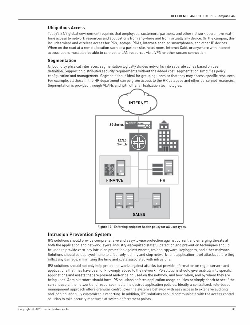
Copyright © 2009, Juniper Networks, Inc. �1
RefeReNCe aRChiteCtuRe - Campus LaN
Ubiquitous AccessToday’s 24/7 global environment requires that employees, customers, partners, and other network users have real-time access to network resources and applications from anywhere and from virtually any device. On the campus, this includes wired and wireless access for PCs, laptops, PDAs, Internet-enabled smartphones, and other IP devices. When on the road at a remote location such as a partner site, hotel room, Internet Café, or anywhere with Internet access, users must also be able to connect to LAN resources via a VPN or other secure connection.
SegmentationUnbound by physical interfaces, segmentation logically divides networks into separate zones based on user definition. Supporting distributed security requirements without the added cost, segmentation simplifies policy configuration and management. Segmentation is ideal for grouping users so that they may access specific resources. For example, all those in the HR department can be given access to the HR database and other personnel resources. Segmentation is provided through VLANs and with other virtualization technologies.
figure 19: enforcing endpoint health policy for all user types
Intrusion Prevention SystemIPS solutions should provide comprehensive and easy-to-use protection against current and emerging threats at both the application and network layers. Industry-recognized stateful detection and prevention techniques should be used to provide zero-day intrusion protection against worms, trojans, spyware, keyloggers, and other malware. Solutions should be deployed inline to effectively identify and stop network- and application-level attacks before they inflict any damage, minimizing the time and costs associated with intrusions.
IPS solutions should not only help protect networks against attacks but provide information on rogue servers and applications that may have been unknowingly added to the network. IPS solutions should give visibility into specific applications and assets that are present and/or being used on the network, and how, when, and by whom they are being used. Administrators should have IPS solutions enforce application usage policies or simply check to see if the current use of the network and resources meets the desired application policies. Ideally, a centralized, rule-based management approach offers granular control over the system’s behavior with easy access to extensive auditing and logging, and fully customizable reporting. In addition, IPS solutions should communicate with the access control solution to take security measures at switch enforcement points.
FINANCE HR
SALES
INTERNET
ISG Series
L2/L3Switch

�� Copyright © 2009, Juniper Networks, Inc.
RefeReNCe aRChiteCtuRe - Campus LaN
FirewallAs purpose-built security devices, firewalls offer high-performance, security, and modular LAN/WAN connectivity. Deployed at various locations throughout the LAN, they protect against network and application level attacks. It’s important to choose a solution that provides adaptive detection threat management security features including stateful firewall, intrusion prevention system, antivirus (anti-spyware, anti-phishing, anti-adware), anti-spam, and Web filtering to protect the network from attack. Additionally, a firewall solution should deliver network segmentation, dynamic routing, and multiple deployment modes to simplify network integration and the deployment of internal security. Another consideration is a solution that provides a modular I/O architecture to deliver high interface density and flexibility for varied connectivity requirements. HA should also be considered so that rapid failover maintains business continuity. Additionally, deploying integrated or consolidated devices should be considered, as doing so may reduce CapEx and OpEx.
Remote Access ServiceRAS enables users to log in from remote sites over a modem or Internet connection and access network services. RAS solutions must be secure and coordinate with IPS to detect identity-based threats and drop malicious application traffic. Ideal solutions also provide clientless granular access control and offer best-in-class endpoint security. For example, a browser-based access solution using SSL provides access for a wide range of endpoints without requiring any client installation while still ensuring optimal security.
Access Control ListsBecause of compliance requirements, enterprises need to prove that only authorized users have access to sensitive company data. They also need to monitor, audit, and log user access to valuable corporate resources. Mainly a wireless issue at most campuses, guests need restricted access on the network. Enterprises can apply risk mitigation by ensuring that users can’t even reach applications unless policy gives them permission. For example, enterprises can dynamically enforce access to guests or open specific services to guests upon login with ACLs. The use of an ACL is also sometimes referred to as filtering, because it regulates traffic by allowing or denying network access. ACLs prevent traffic from entering or exiting the network. Firewall filter parameters can be configured locally or sent by the RADIUS server vendor-specific attributes.
Additional Access SecuritySeveral other port security and threat detection measures should be used to defend against internal and external spoofing, man-in-the-middle, and denial of service (DoS) attacks. These include: MAC limiting, DHCP snooping, dynamic ARP, and IP source guard.
1. MAC Limiting
Network adapters, including those built-in or otherwise, have a Media Access Control address (MAC address) attached to them. This Layer 2 identifier uniquely marks the computer on the network. However, since MAC addresses are not divided into host and network portions like IP addresses, a host can’t determine from the MAC address of another host if the two share the same Layer 2 network segment. Because of that fact, it’s possible to change a MAC address, often referred to as MAC spoofing, thereby accessing restricted resources from a trusted host. MAC limiting is configurable on some switches to prevent MAC flooding and spoofing attacks.
2. DHCP Snooping
Another Layer 2 switch port security feature, Dynamic Host Configuration Protocol (DHCP) snooping, helps protect domain integrity. Working in conjunction with a DHCP server, DHCP snooping allows only clients with specific IP/MAC addresses access to the network when the DHCP server is allocating IP addresses to LAN clients. With DHCP snooping, only a “white list” of IP addresses may access the network. The white list is configured at the switch port level, and the DHCP server manages the access control. Only specific IP addresses with specific MAC addresses on specific ports may access the IP network. Additionally, DHCP requests on all untrusted access ports require inspection and verification. This stops attackers from adding their own DHCP servers on the network and prevents DHCP DoS and rogue DHCP server attacks.
DHCP snooping security feature filters maintain a DHCP snooping binding table of untrusted DHCP messages by preventing DHCP DoS and rogue DHCP server attacks.

Copyright © 2009, Juniper Networks, Inc. ��
RefeReNCe aRChiteCtuRe - Campus LaN
3.
figure �0: Dynamic aRp inspection (Dai)
3. Dynamic ARP (Address Resolution Protocol) Inspection (DAI)
Address Resolution Protocol (ARP) spoofing starts when an attacker sends spoofed ARP messages to an Ethernet LAN. The ARP spoofing occurs when a network node IP address, such as a server or gateway, is stolen and then applied to an attacker’s computer. Network traffic is then sent to the attacker’s computer, who then can modify the data before sending it elsewhere in a man-in-the-middle attack. Alternately, the attacker could launch a DoS attack by associating a non-existent MAC address to the IP address of the gateway. Or the attacker could simply forward the traffic to the actual node after passively sniffing the packets.
DAI is a feature that intercepts ARP packets on untrusted ports and validates them against a DHCP snooping database. Non-matching entries are dropped. This avoids forwarding of traffic to an address impersonating the valid device, preventing man-in-the-middle spoofing attacks and DoS.
4. IP Source Guard
Another port security feature that restricts IP traffic on untrusted Layer 2 access and trunk ports is IP source guard. Working in conjunction with DHCP snooping, IP source guard filters traffic based on manually configured IP source bindings or on what is automatically learned by the DCHP snooping database. This prevents IP spoofing attacks. Any IP traffic coming into the watched ports with an IP address other than those that are automatically or statically assigned will be dropped.
Operational Simplicity and Unified ManagementNetwork operations form a large portion of any IT budget, and any methods of simplifying campus LAN operations help reduce operational expense. The five main challenges that complicate the streamlining of network operations are:
Complex Inefficient Architecture
Trying to address emerging bandwidth, throughput, and port density requirements with low density, single-function legacy solutions, networks in the past have grown bloated with extra layers of ill-suited legacy hardware, many of which are redundant. In fact, Gartner reported in 2007 that 50 percent of Ethernet switch ports are used for server-to-server connectivity in the data center. These old solutions not only fail to meet current campus LAN needs, but also add considerable management complexity and drive up capital and operational expenses.
Inconsistent Feature Set
Most hardware solutions have different operating systems or feature implementations for each platform. One leading switch provider has hundreds of different operating systems in its product line, requiring IT to invest a considerable amount in training to master a variety of interfaces. This also adds a layer of inefficiency and complexity while increasing the potential for misconfiguration when trying to apply consistent enterprise-wide services across the data center LAN, WAN, campus LAN, and remote branch LANs.
Upgrades and Deployments
Testing and deploying operating system upgrades or patches can be a time-consuming and ongoing process due to the number of different operating systems found in most legacy campus LAN solutions, and the varying release schedules to which each adheres.
•
•
•
Email Server L2/L3 Switch
Victim
Attacker

�4 Copyright © 2009, Juniper Networks, Inc.
RefeReNCe aRChiteCtuRe - Campus LaN
Unreliable Monolithic Operating Systems
Legacy hardware solutions have operating systems built on a monolithic architecture with each code function intertwined with the others. If any part of the monolithic program fails—for example, a bug in SNMP—the operating system crashes. Such a fault can cause the line cards to crash or restart, resulting in hundreds of seconds of downtime.
Lack of Unified Management
The lack of unified features also impacts all aspects of setting and managing device configurations, network settings, and security policies. Not only do different interfaces increase the time of each task, but operations costs are further increased as IT needs to visit remote campus locations to configure devices, apply network settings, and set security policies. What’s needed instead is a set of unified and centralized management tools to address these types of operations remotely.
Juniper Networks addresses all of these issues and reduces costs by providing high-density, high-performance infrastructure solutions, JUNOS Software, Juniper Networks Network and Security Manager (NSM), and Juniper Networks J-Web Software.
High-Density, High-Performance Infrastructure SolutionsInstead of adding additional costly layers of legacy equipment and highly skilled IT resources to support the growing number of single-function, low-density devices and services in the enterprise, a new more integrated and consolidated campus LAN solution is needed. High-density, multi-function devices are needed in the new campus LAN. Such devices help collapse costly latency inducing layers, increase performance, decrease choke points, decrease configuration and management tasks, increase reliability, while decreasing total cost of ownership (TCO) as well as ongoing rack and floor space, power, and cooling costs.
Juniper Networks delivers a proven IP infrastructure that meets these challenges, enabling the performance, scalability, flexibility, security, and intelligence needed to not just meet but increase campus user productivity. Juniper’s flexible configurations and price points meet the needs of all campuses while delivering high-performance throughput with services such as firewall, Adaptive Threat Management, VPN, MPLS, IPV6, and Connectionless Network Service (CLNS)-enabled.
For example, Juniper Networks switching solutions offer high-density, high-performance throughput that enables the collapse of multiple layers in the aggregation and core layers. In some instances, Juniper’s solutions support the consolidation of the core and aggregation layers.
figure �1: Juniper’s enterprise framework product portfolio
•
•
ROUTERS
J Series M Series
MX Series T Series
EX3200
EX4200
EX8216EX8208
SWITCHES
JUNOS

Copyright © 2009, Juniper Networks, Inc. �5
RefeReNCe aRChiteCtuRe - Campus LaN
Achieving Operational Simplicity with JUNOS SoftwareJUNOS is the common operating system on all Juniper Networks switches, routers, firewalls, and acceleration solutions. In addition to delivering advanced carrier-class network services, JUNOS delivers a consistent feature set, and centralized management which simplifies planning, speeds implementation, and enables intuitive day-to-day operations and management of any network.
The Power of JUNOS SoftwareFundamental to the value of JUNOS are the “three ones”—one source code, one release train, and one modular architecture. By running a common operating system on all products, Juniper Networks dramatically reduces maintenance and management overhead while ensuring interoperability and a consistent feature set across all products.
figure ��: JuNOs software—the three ones: one source code, one release train, and one modular architecture
Modular ProcessesJUNOS Software is a completely modular operating system, enabling a functional division of labor for seamless development and operation of many advanced features and capabilities. By partitioning the software system, tasks are broken into manageable subsets that interact infrequently and provide new levels of fault-tolerance. Unlike monolithic operating systems, each key JUNOS function executes as an independent process and runs in its own protected memory space. Loading or executing one doesn’t affect the others. One daemon can restart independently without disrupting another or forcing a full system crash or restart. A benefit of this approach is the ability to maintain full control of the switch or router at all times. Because of the separation of control, forwarding, and services, filters can be added in real time to thwart a DDoS attack.
Rollback capabilityJUNOS also offers error-resilient configuration that prevents operators from inadvertently bringing down the network. IT must explicitly commit changes after entering and reviewing all modifications. If a configuration change causes loss of connectivity to the device and no follow-up confirmation is provided, the device automatically reverts back to the previous configuration, restoring connectivity—saving time and ensuring link-level HA for remotely operated campus deployments. In addition to automatically checking for errors or incorrectly constructed configurations that could cause potential problems, JUNOS provides a rollback command to quickly restore any of the 50 prior configurations.
Advanced FeaturesJUNOS also provides a broad spectrum of advanced routing and security software features such as stateful firewall, IPsec, MPLS, and IPv6 without requiring an additional software license. In addition, JUNOS provides comprehensive QoS functions to classify, prioritize, and schedule traffic for applications such as VoIP. For campuses using Virtual Chassis technology, JUNOS enables bidirectional forwarding detection for early detection of node or link failures.
One ArchitectureOne Release
J Series
TX Matrix
One OS
9.3 9.4 9.5

�6 Copyright © 2009, Juniper Networks, Inc.
RefeReNCe aRChiteCtuRe - Campus LaN
BenefitsBy running a common operating system, these Juniper Networks solutions dramatically reduce maintenance and management overhead while ensuring a consistent feature set across all products, as well as a consistent implementation and management of those features. This equates to time savings in all categories of operations. In addition to a reduction in training time, the inherent interoperability across all platforms greatly simplifies new feature deployment, software upgrades, and other network modifications. A single consistent code set also enables customers to qualify and deploy just one release. For many customers, the testing time of a new release is cut from what was used to be months down to just a few weeks. JUNOS also provides features to facilitate fast restoration of previous configurations.
ImpactIn an independent study conducted in 2007, Lake Partners quantified the time savings experienced by Juniper Networks customers using JUNOS across a number of common network operational tasks. The results are presented in Table 1:
Table 1: JUNOS Software Operating Efficiencies (Lake Partners 2007)
Network Operations Task Average JUNOS Software Efficiencyadding infrastructure 29%
upgrading and planned events 23%
troubleshooting and unplanned events 54%
monitoring and Optimizing 24%
average time saved With JuNOs software 25%
This time savings translates to a substantial, tangible cost savings. According to Lake Partners, an infrastructure of any size running JUNOS can save up to 29 percent in operational costs. Seeing that the IT department of a typical enterprise spends 40 to 60 percent of its budget to maintain and enhance basic IT services (McKinsey & Company 2006), this savings could be considerable.
Unified Management with Juniper Networks NSMThe Juniper Networks NSM product is a powerful, centralized management solution that controls the entire device life cycle of firewall/IPSec VPN and IDP devices, including basic setup and network configuration with local and global security policy deployment. Unmatched role-based administration allows IT departments to delegate appropriate levels of administrative access to specific users, thereby minimizing the possibility of a configuration error that may result in a security hole. NSM can easily scale to meet the needs of any enterprise. A wide range of reporting tools are available, enabling IT to view and analyze network traffic, device and VPN statistics, system resources, and other administrative information. IT can also customize templates for commonly used reports and generate these reports on a regularly scheduled basis.
BenefitsNSM lowers operational costs by presenting a graphical user interface (GUI) to simplify complex tasks such as device configuration, supplying device templates to minimize configuration errors, providing investigative tools for complete visibility into the network, and more.

Copyright © 2009, Juniper Networks, Inc. �7
RefeReNCe aRChiteCtuRe - Campus LaN
Remote Configuration and Management with J-WebIn addition to a full-featured command-line interface (CLI), J-Web, a Web-based tool, is available to configure and manage any JUNOS Software-powered device.
figure ��: easy-to-use graphical J-web interface
BenefitsBuilt on JUNOS Software, J-Web offers a GUI for device management that complements the existing suite of element and service management products from Juniper Networks. J-Web provides IT administrators and network operators with simple-to-use tools to quickly and seamlessly monitor, configure, troubleshoot, and manage any switch, router, or firewall.
J-Web even allows non-technical users to commission and bring a router online quickly and easily. It offers seamless GUI access to all of the features and functions of JUNOS, reducing timelines for new service deployments. J-Web can be quickly integrated into existing network management or OSS (Operational Support System) applications such as Micromuse Netcool OMNIbus, Dorado RedCell Manager, IBM Tivoli, and HP Openview, thereby minimizing complexity for the service provider or enterprise customer. Fast, error-free service changes and upgrades can be made with J-Web’s quick configuration wizards, and new services can be rapidly created and deployed with the use of configuration and QoS wizards that allow for real-time changes to service parameters.

RefeReNCe aRChiteCtuRe - Campus LaN
38
Corporate and sales headquarters Juniper Networks, Inc. 1194 North Mathilda Avenue Sunnyvale, CA 94089 USA Phone: 888.JUNIPER (888.586.4737) or 408.745.2000 Fax: 408.745.2100
apaC headquartersJuniper Networks (Hong Kong) 26/F, Cityplaza One 1111 King’s Road Taikoo Shing, Hong Kong Phone: 852.2332.3636 Fax: 852.2574.7803
emea headquartersJuniper Networks Ireland Airside Business Park Swords, County Dublin, Ireland Phone: 35.31.8903.600 Fax: 35.31.8903.601
Copyright 2009 Juniper Networks, Inc. All rights reserved. Juniper Networks, the Juniper Networks logo, JUNOS, NetScreen, and ScreenOS are registered trademarks of Juniper Networks, Inc. in the United States and other countries. JUNOSe is a trademark of Juniper Networks, Inc. All other trademarks, service marks, registered marks, or registered service marks are the property of their respective owners. Juniper Networks assumes no responsibility for any inaccuracies in this document. Juniper Networks reserves the right to change, modify, transfer, or otherwise revise this publication without notice.
8030005-001-EN June 2009 Printed on recycled paper.
To purchase Juniper Networks solutions, pleasecontact your Juniper Networks representative
at 1-866-298-6428 or authorized reseller.
ConclusionThe highly visible enterprise LAN is a core asset that must be accessible anytime from anywhere—offering secure, high-performance services regardless of location. A number of trends are increasing security and performance challenges that existing campus infrastructure solutions can not meet. In addition, existing solutions do not provide the centralized management capabilities critical for reducing costs and streamlining operations. A new campus LAN design that meets campus security, connectivity, and performance challenges while enabling key IT initiatives is needed. This new solution must also scale, offer operational simplicity, and flexibly accommodate new computing trends without an entire redesign.
Juniper Networks solutions, including a new family of high-performance Ethernet switches, redefine the way businesses build campus networks. Offering high port densities, wire-speed connectivity, and high availability in compact, pay-as-you-grow platforms, Juniper’s switches represent a powerful yet cost-effective alternative to the aging and expensive solutions pushed by today’s dominant switch vendors. They enable the collapse of inefficient layers required by traditional solutions. By offering a smaller footprint in the wiring closet, combined with lower power and cooling requirements, Juniper’s switches represent the efficient and “green” solutions users are looking for to power their networks of the future. In addition to a full suite of secure services, Juniper Networks products provide the end-to-end QoS required for sensitive and bandwidth-hungry applications such as unified communications.
JUNOS Software, a single, consistent operating system used across all Juniper Networks switch, router, and firewall products, makes the network infrastructure exceedingly easy to deploy, configure, and upgrade, saving considerable time and operating resources that can be reallocated to further improve business operations and maximize customer satisfaction.
Juniper Networks infrastructure solutions advance the economics of networking, allowing businesses to “change the rules” with their IT investments, and create a truly innovative and competitive environment that helps them increase revenue and raise productivity today and into the future.
About Juniper NetworksJuniper Networks, Inc. is the leader in high-performance networking. Juniper offers a high-performance network infrastructure that creates a responsive and trusted environment for accelerating the deployment of services and applications over a single network. This fuels high-performance businesses. Additional information can be found at www .juniper .net.