can pci dss compliance be achieved in a cloud environment?
TRANSCRIPT

Project final version P. Durkin 1
Can PCI DSS compliance be achieved in a cloud environment?
Durkin, Patrick
Student number:100647746
Supervisor: Geraint Price
Submitted as part of the requirements for the award of the MSc in Information Security at
Royal Holloway, University of London.
I declare that this assignment is all my own work and that I have acknowledged all
quotations from the published or unpublished works of other people. I declare that I have
also read the statements on plagiarism in Section 1 of the Regulations Governing
Examination and Assessment Offences and in accordance with it I submit this project report
as my own work.
Signature Date

Project final version P. Durkin 2
Tables and figures ................................................................................................................................ 5
Executive summary .............................................................................................................................. 6
1 Introduction .................................................................................................................................... 7
2 Defining cloud computing ............................................................................................................ 9
2.1.1 Cloud computing – a business justification................................................................... 10
2.1.2 Summarising cloud computing...................................................................................... 11
2.2 Cloud computing services ..................................................................................................... 11
2.2.1 A brief introduction to virtualisation ............................................................................ 11
2.2.2 Microsoft Cloud Services............................................................................................... 12
2.2.3 Amazon Cloud Services ................................................................................................. 15
2.2.4 Concluding cloud services ............................................................................................. 17
3 An introduction to e-commerce ................................................................................................ 18
3.1 Understanding payment card transactions .......................................................................... 18
3.1.1 The entities involved with payment card transactions ................................................. 19
3.1.2 How payment cards work ............................................................................................. 19
3.2 An e-commerce system model ............................................................................................. 19
3.3 E- commerce system vulnerabilities ..................................................................................... 20
3.4 Threats to e-commerce ......................................................................................................... 20
4 The Payment Card Industry Data Security Standard (PCI DSS) ........................................ 23
4.1 The birth of PCI DSS and the PCI Security Standards Council ............................................... 23
4.1.1 What are the PCI DSS requirements ............................................................................. 23
4.1.2 PCI DSS compliance ....................................................................................................... 24
4.1.3 Reasons to comply with PCI DSS ................................................................................... 26
5 Virtualisation and PCI DSS ....................................................................................................... 27
5.1 Virtualisation and PCI DSS - the new risks ............................................................................ 27
5.2 PCI SSC recommendations for virtual technologies .............................................................. 29
5.2.1 General recommendations ........................................................................................... 29
5.2.2 Recommendations for mixed-mode environments ...................................................... 30
5.2.3 Recommendations for cloud computing environments ............................................... 30
5.3 Summarising PCI DSS and virtualisation technologies .......................................................... 30
6 Hypervisor architecture and security controls ........................................................................ 32
6.1.1 ESXi architecture ........................................................................................................... 32

Project final version P. Durkin 3
6.2 Memory management and security ..................................................................................... 34
6.2.1 Virtual memory allocation ............................................................................................ 34
6.2.2 Managing memory within ESXi ..................................................................................... 35
6.2.3 Transparent Page Sharing (TPS) .................................................................................... 35
6.2.4 Memory reclamation .................................................................................................... 36
6.2.5 Memory hardening ....................................................................................................... 37
6.2.6 Summarising memory management ............................................................................. 37
6.3 CPU and process isolation ..................................................................................................... 38
6.3.1 Summarising CPU and process isolation ....................................................................... 38
6.4 Security and isolation at the VM ........................................................................................... 38
6.4.1 VMs configuration files ................................................................................................. 39
6.4.2 Managing VMs configuration ........................................................................................ 39
6.4.3 Summarising security and isolation at the VM ............................................................. 39
6.5 Security and isolation at the virtual network........................................................................ 40
6.5.1 Virtual network architecture......................................................................................... 41
6.5.2 Virtual network segregation ......................................................................................... 41
6.5.3 Common switch and VLAN attacks ............................................................................... 42
6.5.4 Hardening virtual networks .......................................................................................... 42
6.5.5 Summarising isolation and security at the virtual network .......................................... 43
6.6 Introducing the Trusted Platform and Intel technology ....................................................... 43
6.6.1 Paging and segmentation Intel eXecute Disable (XD) ................................................... 44
6.6.2 Intel VT-x hardware virtualisation technology .............................................................. 44
6.6.3 TPM – The Trusted Platform Module ........................................................................... 45
6.6.4 How the TPM works ...................................................................................................... 48
6.6.5 An Introduction to Intel Trusted eXecution Technology (TXT) ..................................... 49
6.6.6 Summary of trusted platform and Intel technology ..................................................... 49
6.7 Summarising hypervisor architecture and security controls ................................................ 50
6.7.1 Common Criteria ........................................................................................................... 50
7 Monitoring and audit capabilities.............................................................................................. 52
7.1 Monitoring the hypervisor .................................................................................................... 52
7.1.1 Introducing the Common Information Model (CIM) .................................................... 52
7.2 Monitoring the supporting infrastructure ............................................................................ 53
8 Conclusion ................................................................................................................................... 54
8.1 Ideas for development .......................................................................................................... 55

Project final version P. Durkin 4
8.2 My answer ............................................................................................................................. 57
Bibliography ........................................................................................................................................ 58
Appendices .......................................................................................................................................... 61

Project final version P. Durkin 5
Tables and figures
Figure 1 Types of Hypervisor [5] ...................................................................................................... 12
Figure 2 Windows Azure Architecture [12] ..................................................................................... 14
Figure 3 Privileged ring model[15] .................................................................................................. 15
Figure 4 AWS Firewall Isolation[15] ................................................................................................ 16
Figure 5 E-Commerce System Architecture[17] ........................................................................... 20
Figure 6 ESXi Hypervisor Architecture [25] .................................................................................... 33
Figure 7 Virtual Memory Mapping [27] ............................................................................................ 34
Figure 8 Virtual Network Architecture [33]...................................................................................... 41
Figure 9 TPM Components [35] ....................................................................................................... 46
Figure 10 CIM Architecture [25] ....................................................................................................... 52
Figure 11 Log Integrity Service ........................................................................................................ 56
Table 1 PCI DSS Objectives and Requirements[16] .................................................................... 24
Table 2 PCI DSS Merchant Levels[19] ........................................................................................... 25
Table 3 PCI DSS Assessment Requirements[19] ......................................................................... 25
Table 4 PCI SSC General Recommendations Specific to Virtualisation Security.................... 29
Table 5 Summary of the Factors and Recommendations of the PCI SSC ............................... 31
Table 6 VM configuration files [31] .................................................................................................. 39
Table 7 TPM Requirements and the Associated Technologies [35] .......................................... 44
Table 8 Relevant Security Objectives [40] ..................................................................................... 51
Table 9 Virtual Machine Settings [32] ............................................................................................. 61
Table 10 Virtual Network Settings [42]............................................................................................ 62
Table 11 PCI Requirement to VMware mapping [41] ................................................................... 63

Project final version P. Durkin 6
Executive summary
Cloud computing is being marketed as the solution to the majority of an organisation’s IT
needs. The Payment Card Industry Data Security Standard (PCI DSS) was created to
protect cardholder data. This dissertation provides the definitions of what cloud computing
actually is and the services offered, a summary of two services providers cloud services and
a review of what the Payment Card Industry Security Standards Council's concerns
regarding virtualisation. By understanding the architecture of E-Commerce solutions and the
controls available within virtualisation and hardware technologies, it has been possible to
conclude that PCI DSS compliance is achievable within a cloud hosted environment.

Project final version P. Durkin 7
1 Introduction
Today, cloud computing is being marketed as the solution to the majority of an organisation’s
IT needs. Combining this with the growth of e-commerce the advantage for organisations
using a cloud service's flexibility to meet business requirements seems beneficial. However,
before moving IT services to the cloud, an organisation must consider the contractual, legal
and regulatory obligations they have to the protection of data.
The storing and processing of data may require compliance to laws and standards such as
the Data Protection Act, HIPPA, government standards and PCI DSS. When the data is
hosted within an organisations own environment, or in a dedicated private hosting solution,
system boundaries can be relatively easily defined. This is not the case when using shared
resources such as a cloud service. How can an organisation be assured of where their data
actually is? Who has access to their: data, network traffic and system administration
interfaces? How can unauthorised access be detected and how are data confidentiality and
integrity services provided?
Whilst these questions should be considered in any environment, the problems are
compounded when using virtualisation instead of physically separate resources. This is due
to the different levels of administration, resource separation and data destruction. This
dissertation answers the question - can PCI DSS compliance be achieved in a cloud
environment?
To do so, it is first necessary to introduce the reader to the concepts of:
Cloud computing - This will be covered in chapter 2. This chapter will focus on what
is the meaning of cloud computing and, after a brief introduction to the concept of
virtualisation, will include an overview of the cloud service offerings of Microsoft and
Amazon.
E-Commerce - Chapter 3 will focus on what is e-commerce, a typical architecture
and the threats to e-commerce.
Payment Card Industry Data Security Standard (PCI DSS) - Chapter 4 will provide
an introduction to the PCI Security Standard Council (PCI SSC), the requirements of
PCI DSS, along with how and why to comply with the standard.
This project will then take a closer look at the:
PCI DSS and virtualisation – Chapter 5 will introduce the new risks presented by
virtualisation technologies, as perceived by the PCI SSC. This chapter will assess
the PCISSC concerns and recommendations. This should allow a better
understanding of what is required to enable PCI DSS compliance within a virtualised
environment.
Hypervisor architecture and security controls – Chapter 6 will review the controls
available to provide the security and isolation of components within a virtualised
environment using VMware ESXi. This chapter will include a basic introduction to
hardware technologies that assist in the security of hypervisor technology. This
chapter will conclude with a look at trust and assurance of the controls available.
Monitoring and Audit – Chapter 7 reviews the monitoring and audit methods
available to provide compliance with the PCI DSS.

Project final version P. Durkin 8
Conclusion – Chapter 8 will build on the findings of the previous chapters to discuss
what is missing and suggest possible compensating controls. The chapter will
conclude with a view of whether PCI DSS is achievable in a cloud environment.
This dissertation will now look at cloud computing and what it really means.

Project final version P. Durkin 9
2 Defining cloud computing
There are many definitions for ‘cloud computing’. For example, Gartner defined cloud
computing as “A style of computing where scalable and elastic IT capabilities are provided
as a service to multiple customers using Internet technologies”.1
‘The cloud’ is a representation of the Internet2. In the context of computing, 'Cloud ' like
'Internet' is just a noun, an abstract idea that has been accepted by the IT industry. 'Cloud
computing' has been adopted by many to describe various services provided, usually on an
on-demand, pay as you go basis, by a service provider to a customer, which are accessed
via the Internet (or the cloud).
Cloud computing usually includes five essential characteristics[1]:
On-demand self service - customers can provision resources without human
interaction with the service provider.
Broad network access - resources are accessed via networks.
Resource pooling - computing resources are pooled to serve multiple consumers with
different physical and virtual resources dynamically assigned and reassigned
according to consumer demand.
Rapid elasticity - capabilities can be scaled up and down rapidly and in some cases
automatically to meet demands.
Measured service - resource usage can be monitored, controlled, and reported to
provide a pay on demand business model.
The Gartner definition includes the term "scalable and elastic" but I would suggest that this is
only to the extent of which the service provider can allocate the required resources. Most
services are scalable and elastic to the limits of the resources and capabilities of the service
provider at a given time. I feel the benefit of the cloud service is the speed and ease of the
expansion and reduction of allocation of resources available to the customer to meet
demand requirements.
Cloud computing is offered to consumers in the form of three cloud service models, usually
described as[1]:
Software as a Service (SaaS) - a consumer is offered the use of software hosted and
supported by a service provider. An example would be an email system that a
customer accesses via a web browser.
Infrastructure as a Service (IaaS) - a consumer can develop and manage an
application on an operating system and network infrastructure that is hosted and
supported by a service provider. (The consumer does not have control nor manage
the underlying operating system or network infrastructure).
Platform as a Service (PaaS) - a consumer can provision resources such as
processing power and storage to run applications and operating systems within a
virtual environment hosted by the service provider. (Whilst the consumer does not
1 [http://blogs.gartner.com/daryl_plummer/2009/01/27/experts-define-cloud-computing-can-we-get-a-little-
definition-in-our-definitions/ ] 2 In Network diagrams the Internet is often graphically represented by a picture of a cloud.

Project final version P. Durkin 10
control nor manage the underlying virtual environment, the consumer may have
limited access to some network devices).
Another new term that is being introduced is a 'private cloud'[1]. This is an infrastructure
hosted by an organisation or a service provider, dedicated for the sole use of an
organisation. This gives the flexibility of cloud computing providing SaaS, PaaS and IaaS,
but the control of the data can remain within the organisation (if hosted internally). The use
of the metering within the measured service characteristic of the private cloud can facilitate
in the understanding of the true IT requirements and costs of an organisation on a
department by department basis. This is now marketed to an organisation as ‘IT as a
Service’ (ITaaS)[2].
The combination of multiple cloud services is known as a hybrid cloud.
Gartner suggest the cloud is going to continue to grow and the utilisation of cloud services
will become part of an organisations IT strategy. The Gartner top 10 strategic technologies
for 2011 include cloud computing: "Cloud computing services exist along a spectrum from
open public to closed private. The next three years will see the delivery of a range of cloud
service approaches that fall between these two extremes. Vendors will offer packaged
private cloud implementations that deliver the vendor's public cloud service technologies
(software and/or hardware) and methodologies (i.e., best practices to build and run the
service) in a form that can be implemented inside the consumer's enterprise. Many will also
offer management services to remotely manage the cloud service implementation. Gartner
expects large enterprises to have a dynamic sourcing team in place by 2012 that is
responsible for ongoing cloud sourcing decisions and management."3
2.1.1 Cloud computing – a business justification
Independent of cloud computing, moving from self hosted IT services to outsourced IT
service has been a business model for some time now. Two primary economic implications
are:
A shift of capital expenses (CAPEX) to Operational expenses (OPEX).
The potential reduction in OPEX when operating the IT services.
This shift from CAPEX to OPEX can lower the financial barriers for the initiation of a new
project. In a self hosted model the hardware and licences are purchased at the start. This
cost is incurred whether the project is successful or not. In an outsourced model the start-up
fees are typically equivalent to one month's operational cost, and a commitment to one
year's costs up front.
Typically the one year cost is roughly the same or slightly lower than the CAPEX cost for the
equivalent project, but this is offset against the reduced OPEX required to operate the IT
service. In a cloud model there are typically no start-up fees. The process is usually sign up,
authorise a credit card and start using the cloud services [3].
This difference in economics between the private and outsourced hosting models and the
cloud is due to the cost structures for cloud infrastructures are better than the other models.
The primary reason is simply the economics of volume. Supermarkets can buy consumer
goods at a much lower price that a consumer because of their bulk purchases. In computing
services the goods are equivalent to computing, storage, power, and network capacity [3].
3 [http://www.gartner.com/it/page.jsp?id=1454221] as on 02/06/2011

Project final version P. Durkin 11
2.1.2 Summarising cloud computing
To summarise, cloud computing is basically a hosted service providing dynamic virtual
servers and/or applications. Cloud computing differs from a dedicated hosted service only by
the fact that it is often a shared architecture and charged on-demand or on a pay as you go
basis.
To complete this section on cloud computing, this dissertation will look at cloud service
offerings from Microsoft and Amazon (These where randomly chosen from a selection of
cloud service providers). The aim being to understand:
Which services are deemed cloud services?
What the "cloud services" are actually offering (from a technological perspective).
A brief overview of the security features.
This should provide an understanding of what cloud services could potentially be used to
host a PCI DSS compliant e-commerce solution. This chapter will also include any claims
that the service providers may have to the compliance of their services with PCI DSS.
2.2 Cloud computing services
A brief introduction to virtualisation has been included in this section as it is necessary to
have a basic understanding of the virtualisation concepts on which cloud computing services
are based. Later chapters in this dissertation will provide a more in-depth look at
virtualisation technologies.
2.2.1 A brief introduction to virtualisation
As described by Halter & Wolf[4], virtualisation can be considered as abstracting the physical
boundaries of a technology. Servers will no longer need dedicated hardware resources but
instead will run inside Virtual Machines (VMs). In a VM, the physical hardware is emulated
and presented to the guest operating system as if it actually existed. This enables the
running of multiple (and sometimes different) operating systems within VMs on one physical
host system.
Virtualisation software protects and partitions host systems resources (the CPU, memory,
disks and peripherals). This is done by creating a virtualisation layer within the host
operating system or directly on the hardware. ‘Running on the metal’ is an expression to
describe virtualisation software that runs directly on the hardware. As shown in Figure 1,
there are two basic types of Hypervisor:
Type I Hypervisor – ‘runs on the metal’ providing a platform on which a guest
machine can operate using the physical resources of the host system.
Type II Hypervisor - runs on an operating system providing a platform on which a
guest machine can operate using the physical resources of the host system.
Each operating system can run on its own VM and the partitioning process will prevent data
leaks and keeps VMs isolated from each other [4].

Project final version P. Durkin 12
Type II Hypervisor
CPU RAM Disk
Guest operating systems
Operating SystemType I Hypervisor
CPU RAM Disk
Guest operating systems
Figure 1 Types of Hypervisor [5]
It is the partitioning of a host system to support the concurrent execution of multiple
operating systems that poses several challenges. Firstly, VMs must be isolated from one
another; it is not acceptable for the execution of one to adversely affect the performance of
another. This is particularly true when VMs are owned by mutually untrusting users.
Secondly, it is necessary to support a variety of different operating systems to accommodate
the heterogeneity of popular applications. Thirdly, the performance overhead introduced by
virtualization should be small [6].
The concept of sharing hardware and system resources is not new. Mainframe systems
used to provide timesharing as far back as the 1960's. The first large scale time sharing
system was created in 1964 at the Dartmouth college:
"On May 1 at 4:00 a.m., the Dartmouth College Time-Sharing System (DTSS) was born as it
successfully executed two identical programs from two teletypes simultaneously, giving the
correct answer to each."4
Today, virtualisation extends beyond the VM including technologies such as:
Virtual networks (VLANS) operating within physical network environment.
Network file systems such as Distributed File System (DFS) allow access to files
without the actual physical location being known.
Virtual storage - physical storage resources are aggregated into storage pools, from
which the logical storage is created.
This basic concept of virtualisation should allow for the better understanding of the services
described in the following sections: 2.2.2 Microsoft Cloud Services and 2.2.3 Amazon Cloud
Services.
2.2.2 Microsoft Cloud Services
Microsoft summarise the power of the cloud as:
"If you had to sum up the power of the cloud, the term IT as a Service (ITaaS) fits the bill.
Today, CIOs are leveraging the cloud for parts or all of their data centre and IT management
needs. Some are moving physical infrastructure into the cloud, called Infrastructure as a
Service (IaaS). Some are moving server platform and management to the cloud, called
Platform as a Service (PaaS), while others are simply consuming entire software workloads
running in the cloud using Software as a Service (SaaS)."5
4 http://www.dartmouth.edu/comp/about/archive/history/timeline/1960s.html
5 [http://www.microsoft.com/en-GB/cloud/reports/9074.aspx] as on 03/06/2011

Project final version P. Durkin 13
The Microsoft Cloud offering is in the form of five services6:
Windows 365: Productivity - This is an online Microsoft hosted service providing
consumers with the Office desktop suite (Word, outlook, etc.) with cloud-based
versions of Microsoft Exchange Online, Microsoft SharePoint Online and Microsoft
Lync Online via the Internet. As with most Cloud services this is a multi-tenant
service and provides separation service via ‘specially engineered active directory
technology’. Authentication is provided by either a Microsoft Online ID or by
federated identification using corporate IDs and the Microsoft Active Directory
Federation Services. All clients to Windows 365 connections established over the
Internet are protected by 128-bit SSL (Secure Socket Layer)7 encryption and integrity
services [7].
Windows Azure: Cloud Platform - Windows Azure is a Global Microsoft hosted,
shared platform to host applications (written in a .Net supported language) in a way
that storage and processing power can be changed to meet the customer
requirements.
Windows server (hyper-v): Private Cloud - This is a Windows Server 2008 operating
system that provides hypervisor-based server virtualization technology. This enables
an organisation to create their own Cloud service running multiple VMs on a single
physical machine [8].
Microsoft dynamics CRM Online: CRM Online - this is an online Customer
Relationship Management tool. Providing tools for sales, marketing and customer
service [9].
Windows Intune: Security and Management - This is a central management tool for
the securing and management of PCs (Personal Computers). Windows Intune
enables the remote management of updates, security policies and Malware
Protection. Windows Intune also provides inventory and monitoring services and a
capability of assistance for the remote user [10].
The Microsoft cloud services fit into the cloud services models:
Software as a Service (SaaS), in the form of Windows 365, Windows CRM Online
and Windows Intune.
Infrastructure (IaaS) or Platform as a Service (PaaS), in the form of Windows Azure,
(and an operating system in the form of Windows Server Hyper-v).
The only service being offered by Microsoft that could potentially host an e-commerce
solution is Windows Azure (Windows Server Hyper-v is a not a service but a product8).
Windows Azure does not provide a platform to run virtual operating systems - it is the
operating system. Windows Azure gives consumers a platform to develop and manage their
applications. This fits with the model of Platform as a Service (PaaS). Microsoft does have a
beta version of a VM role which, when released would provide a customer with a Windows
2008 server VM hosted on the Windows Azure platform[11]. This will fit with the model of
Infrastructure as a Service (IaaS).
6 [http://www.microsoft.com/en-gb/cloud/default.asp] as on 03/06/2011
7 for more information on SLL may be found here: http://en.wikipedia.org/wiki/Transport_Layer_Security
8 Windows Server Hyper-v could be used by an organisation or a service provider as a virtual platform for a cloud
service.

Project final version P. Durkin 14
Windows Azure provides two functions - an application hosting service and a storage
service. There are two ways in which a customer may manage their hosting or storage
service. Either via a web site, (Windows Azure Portal) using the Live ID created at the time
of subscription, or a Service Management API (Application Programming Interface). The
Service Management API (SMAPI) is accessed via a RPC (Remote Procedure Call)
protocol9 running over SOAP10. This Protocol is in turn protected by 128-bit SSL and is
authenticated using a certificate containing the public key of a customer generated
public/private key pair11. Customers may monitor their applications using both the Windows
Azure Portal and the SMAPI [12].
A level of security is provided to the application environment by a least privileged policy. This
means that customers are not granted administrative access to their VMs and hosted
customer applications operate in a low privileged account.
Windows Azure Storage uses secret keys for access control. When a customer subscribes
to the Windows Azure Storage service they may create one or more storage accounts. Each
storage account has a corresponding secret key which gives access to all data within that
storage account.
Windows Azure services run on a multi-tiered architecture (see Figure 2) consisting of an
underlying Fabric Controller (FC) which provides access to hardware devices and resources.
Running on the FC is a Fabric Agent (FA) this manages the Guest Agent (GA) within the
customers guest operating system.
The FC uses a set of credentials to authenticate it to hardware devices under its control.
These credentials are stored in an internal data store which is encrypted with a master key.
Credentials are decrypted and encrypted as and when required.
Fabric Agent (FA)
Fabric Controller (FC)
Hardware
Device
Hardware
Device
Hardware
Device
Guest Agent
(GA)
Guest Agent
(GA)
Guest Agent
(GA)
Customer Operating
system
Customer Operating
system
Customer Operating
system
Un
idire
ctio
na
l
Co
mu
nic
atio
n
Figure 2 Windows Azure Architecture [12]
Additional separation is provided by unidirectional communication (protected by SSL)
between the FC and the FA. The FA can only respond to requests from the FC. The FA
cannot initiate communication between the FC or any other privileged internal nodes [12].
9 The Remote Procedure Call (RPC) protocol is documented in RFC 1831: http://www.ietf.org/rfc/rfc1831.txt
10 for more information on SOAP please see: http://www.w3.org/TR/soap12-part1/#intro
11 Suggested reading for more information on public key cryptography is: Cryptography, A very short introduction.
By Fred Piper and Sean Murphy

Project final version P. Durkin 15
With regards to PCI DSS within the frequently asked questions about Microsoft Azure,
Microsoft makes the following statement: "Microsoft makes no claim regarding these
standards for 3rd party hosting. There are ways to develop cloud based applications to use
3rd party PCI data processers that may keep the cloud application itself out of scope" [13].
A link is included to documentation for PayPal services [11].
2.2.3 Amazon Cloud Services
Amazon offer a number of cloud services via AWS (Amazon Web Services) including but not
limited to:
Amazon Elastic Compute Cloud (EC2).
Amazon Simple Storage Service (S3).
Amazon Elastic Block Storage (EBS).
Amazon Virtual Private Cloud (VPC).
Amazon EC2 is a flexible virtualised server environment for customers to run instances of
various operating systems on a pay as you go on demand basis. Amazon S3 and EBS are
database services. Amazon VPC is an isolated virtual environment within the AWS
environment. Amazon freely provides information to the security of their cloud services
offering. Amazon will, upon the completion of a non-disclosure agreement, provide the
details of the SAS70 compliance. This can be used in the PCI compliance process [14].
The Amazon cloud infrastructure is a proprietary hypervisor, based on a hardened version of
Xen. The AWS hypervisor operates a security model based on privileged rings (see
Figure 3). The CPU provides four modes called rings. (Ring 0 being most privileged and ring
3 least privileged). Processes running in a higher ring cannot access lower rings. The host
operating system (the proprietary hypervisor) operates in ring 0, the guest operating systems
run in ring 1 and applications run in ring 3. This provides additional separation and results in
guest operating systems being unable to access the proprietary hypervisor processes.
Ring 0
Ring 2
Ring 3
Ring 1
Applications
Guest Operating SystemsHypervisor
Figure 3 Privileged ring model[15]

Project final version P. Durkin 16
Utilising this model, the hypervisor can provide isolation for different instances of VMs
running on the same physical machine.
Additional isolation is provided by a firewall which runs at the same layer as the hypervisor
providing traffic flow control between the physical interfaces and the instances virtual
interfaces. This provides the same level of separation protection between each instance as
is provided between an individual instance and the internet (see Figure 4) [15].
AWS Firewall
Customer Operating systems
AWS Hypervisor
Internet
Virtual
Interface
Virtual
Interface
Virtual
Interface
Virtual
Interface
Figure 4 AWS Firewall Isolation[15]
Amazon claims that PCI DSS compliance can be obtained in their AWS for a cardholder
environment: "Our PCI Service Provider status means that customers who use our services
to store, process or transmit cardholder data can rely on our PCI compliance validation for
the technology infrastructure as they manage their own compliance and certification,
including PCI audits and responses to incidents " [14].
“Our service provider compliance covers all requirements as defined by PCI DSS for
physical infrastructure service providers. Moving the entire cardholder environment to AWS
can simplify your own PCI compliance by relying on our validated service provider status"
[14].
Published on the Amazon AWS PCI Frequently asked questions site12, Amazon do clarify
that this is not an automatic compliance: "All merchants must manage their own PCI
certification.
“For the portion of the PCI cardholder environment deployed in AWS, your QSA (qualified
security assessor) can rely on our validated service provider status, but you will still be
required to satisfy all other PCI compliance and testing requirements that don’t deal with the
technology infrastructure, including how you manage the cardholder environment that you
host with AWS."
Amazon also provides information on their website12 to which AWS services are compliant
with PCI DSS: "The entire infrastructure that supports EC2, S3, EBS and VPC is compliant
and there is no separate environment or special API to use. Any server or storage object
deployed in these services is in a PCI compliant environment, globally."
12
[http://aws.amazon.com/security/pci-dss-level-1-compliance-faqs/] as on 07/06/2011

Project final version P. Durkin 17
These service offerings imply that the foundation of the cloud service is the system hardware
and the hypervisor that the service providers use for their respective virtual environments.
Therefore, the infrastructure security would be reliant upon the controls that can be provided
for access control and separation of resources within the virtual environments. The hosted
application security is reliant on the security of the underlying aforementioned services and
the controls within the instances of hosted VM operating systems on which they are
installed. All of these components are included within the scope of the PCI DSS to provide
the assurance to the customers that their data and services are appropriately protected [16].
2.2.4 Concluding cloud services
Cloud computing removes the investment commitment to dedicated hardware for customers
and improves resource utilisation for service providers. Both of the service offerings above
are suitable for hosting applications. The next chapter of this dissertation will look at e-
commerce, typical e-commerce architecture, and the vulnerabilities and threats to e-
commerce.

Project final version P. Durkin 18
3 An introduction to e-commerce
E-commerce or electronic commerce is the buying and selling of products or services via the
Internet or other computer networks. E-commerce is an established and viable business
model and it is getting bigger:
"In Western Europe, Forrester projects online retail sales will rise 13.10% this year over
2010, to €91.90 billion ($125.57 billion) from €81.25 billion ($111.02 billion). As in the United
States, Forrester projects the annual rate of increase will decline slightly in each of the next
several years, with online retail sales in 2015 rising 7.84% over 2014, to 133.64 billion Euros
(US$182.53 billion) from 123.92 billion Euros (US$169.31 billion). The projected compound
annual growth rate for Europe over 2010-2015 is 12.47%, reports InternetRetailer.com"13
There are four basic types of e-commerce:
Business to Consumer (B2C) - this is where the seller is a business organisation and
the buyer is a consumer. (This type emulates buying from a shop).
Business to Business (B2B) - this is where the seller is a business organisation and
the buyer is a business organisation.
Consumer to Consumer (C2C) - this is where the seller is a consumer and the buyer
is a consumer.
Consumer to Business (C2B) - this is where the consumer can name a price they are
willing to pay for a requirement and business organisations can decide whether to
meet the requirement for the price. As this is consumer driven and not seller driven
this becomes a C2B model.14
To support these models a means of payment is required, in a physical commerce system
there are four main methods of payment [17]:
Cash
Credit card
Cheque
Credit/debit (cash transfers)
With e-commerce payment is still required but the methods are different. Electronic payment
methods have evolved from those within the physical commerce system and consequently
have much in common. Electronic money systems are not new, electronic transfers of
money have been conducted by banks since the 1960's and bank customers have been able
to draw cash from ATM's since the 1970's [18].
This dissertation is addressing PCI DSS in the cloud therefore keeping in line with this
subject it is necessary to understand how and where the payment card data is stored and
used within an e-commerce solution.
3.1 Understanding payment card transactions
This section will introduce some of the basic principles needed to understand payment card
transactions. This will include the entities involved, the transaction process and the
13
http://www.fortune3.com/blog/2011/01/ecommerce-sales-2011/ 14
There are conflicting definitions for C2B. many sources cite C2B simply as the seller is a consumer and the buyer is a business organisation. (http://en.wikipedia.org/wiki/Consumer-to-business)

Project final version P. Durkin 19
architecture requirements for a typical e-commerce system. This section will conclude with
an overview of some of the threats and vulnerabilities of payment card details within an e-
commerce system.
3.1.1 The entities involved with payment card transactions
The list below shows all the entities involved within a payment card transaction [19].
Card holder - a person holding a payment card (the consumer in B2C).
Merchant - the business organisation selling the goods and services (The merchant
sets up a contract known as a merchant account with an acquirer).
Service provider15 - this could be the merchant (Merchant service provider (MSP)) or
an independent sales organisation (ISO) providing some or all of the payment
services for the merchant.
Payment processor - this is a particular example of a MSP.
Acquirer or acquiring bank - this connects to a card brand network for payment
processing and also has a contract for payment services with a merchant.
Issuing bank - this entity issues the payment cards to the payment card holders.
Card brand - this is a payment system (called association network) with its own
processors and acquirers (such as Visa, MasterCard and Amex).
This dissertation is focusing on an e-commerce system's ability to comply with PCI DSS in a
cloud hosted environment. With this in mind, the primary focus will be on payment card
transactions from the merchant perspective (as it will be a merchant that is providing the e-
commerce solution).
3.1.2 How payment cards work
Basically payment cards work using two components. The first component, the 'transaction
authorisation', is where a message containing the transaction details is sent to the card
issuer requesting authorisation for the payment. The card issuer then authorises the
payment. This guarantees payment to the merchant.
The second component known as 'clearing and settlement' is where the merchant submits
the authorised transaction for payment (payment is usually received within 1 - 3 days) the
transaction then appears in the card holder's statement [20].
In an e-commerce system the card transaction steps required from the merchant are
performed by the e-commerce application. Section 3.2 will introduce the e-commerce system
model. By combining the understanding of the e-commerce system model and the required
communications to complete a transaction, the potential vulnerabilities to the payment card
data can be better understood.
3.2 An e-commerce system model
Generally most e-commerce systems can be represented by a three tier model. The three
component parts are the client side, the service system and the back end system (See
Figure 5).
15
This is a service provider with reference to payment cards and not to be confused with a hosting company as a service provider.

Project final version P. Durkin 20
Client Side
Internet
Firewall
Service System Back-end System
Web Server
Application Server
Database Server
Server Side
Figure 5 E-Commerce System Architecture[17]
The service system and the back-end system are commonly known as 'server side'. The
client side connects users to the server side, this serves the users’ requests. The service
system then connects to the backend to fulfil the user's request. From a business
perspective the client side provides the customer interface, the service system provides the
business logic and the back-end provides the required data to complete a transaction [17].
3.3 E- commerce system vulnerabilities
The transaction process highlights the requirement for communication between the users,
merchant and card issuer. These communications must be protected to ensure
confidentiality and integrity of the transaction details. This will prevent eavesdropping and
data manipulation of the transaction details.
By understanding the e-commerce system architecture it becomes apparent that the
payment card data will be vulnerable if someone trying to obtain the payment card details
can access the component parts of the server side system. Additionally, the communications
between the component parts of the server side must be protected to ensure confidentiality
and integrity of the transaction details.
3.4 Threats to e-commerce
Threats to credit card data via web and online services are a reality. With the very real threat
of payment card details being targeted by organised crime and criminals, the payment card
industry have recognised the requirement for a minimal requirement for the security controls
protecting payment card information within systems. Cyber crime - illegal activity utilising
computer systems and networks - is now recognised by courts. Law enforcement authorities
and judiciaries are now acting to deter such activities. The law applies to people, not
technologies. Therefore, once the perpetrator is identified, a crime committed via the Internet
can indeed lead to prosecution and imprisonment.
The UK Government has stated that cyber crime costs the UK economy £27billion a year.
This is made up of the following [21]:
£21 billion of the costs to business.
£2.2 billion to government.
£3.1 billion to citizens.
Even the UK National Security Council has stated that attacks on computer networks and
systems represents one of the most biggest emerging threats to the UK and has already

Project final version P. Durkin 21
agreed to commit a further £500 million to bolster cyber security fraud in protecting key
infrastructure and defence assets. In addition the UK is to opt in to a European Union
directive to tackle the ‘real and growing’ threat posed by cyber crime [22].
Below are statements from two of the leading payment card companies on the subject of
payment card details:
"Customers who pay using a Visa payment card want and deserve assurance that their
account information is safe."16
"The card payment industry is facing the increasing threat of data theft. To date, criminals
have stolen millions of customer card records. In 2008, Visa reported that merchants could
have avoided most security breaches if they had implemented the following measures:
Remove sensitive authentication data and limit data retention.
Protect the perimeter, internal and wireless networks.
Secure application.
Protect through monitoring and access control.
The industry recognised the magnitude of the issue and the urgent requirement to introduce an efficient and effective security mechanism. Consequently, in order to secure customer data and confidence, card payment companies joined forces to create the Payment Card Industry Data Security Standard (PCI DSS)."17
Below are several examples of articles in the press this year of structured attacks directed at
company online resources that resulted in the unauthorised disclosure of payment card
details. This serves to demonstrate the vast scale of these fraudulent activities.
(i) BBC News 21 January 2011
"Cyber thieves are cashing in after stealing credit cards in a hack attack on the website of
cosmetics firm Lush.
The online shop was shut down on 21 January and its home page replaced with a message
revealing the attack."18
(ii) Daily Mail 28th April 2011
"Credit card alert as hackers target 77 million PlayStation users
Millions of people may be issued with new credit cards over fears their banking details have
been stolen by thieves hacking into the Sony PlayStation Network.
The personal information of 77million people around the world is thought to have been
compromised."19
(iii) BBC News 8 June 2011
"London university students jailed for credit card fraud Irfan Ahmed, of Cricklewood, north-
west London, and Faiyaz Mohammed, of nearby Willesden, bought stolen credit card details
online.
16
[http://www.visaeurope.com/en/businesses__retailers/payment_security/overview.aspx] as on 09/06/2011
17 [http://www.barclaycardbusiness.co.uk/pcidss/what-is/why-do-we-need-it.php] as on 09/06/2011
18 [http://www.bbc.co.uk/news/technology-12254282] as on 09/06/2011
19 [http://www.dailymail.co.uk/sciencetech/article-1381000/Playstation-Network-hacked-Sony-admits-hackers-
stolen-77m-users-credit-card-details.html#ixzz1OmfJL42E] as on 09/06/2011

Project final version P. Durkin 22
Both were jailed for 10 months at the Old Bailey after admitting possessing articles for used
in fraud.
The credit card details were bought from crime website Ghostmarket, run by 19-year-old
former public schoolboy Nick Webber who was jailed in March for five years."20
These threats and the potential vulnerabilities of the e-commerce systems led to the development of a standard that should be adhered to and certified against. This standard was developed by the credit card industry with an objective of creating a benchmark minimum acceptable level of security for systems holding or processing payment card details. This standard is the PCI DSS Payment Card Data Security Standard (PCI DSS).
The following chapter gives some details of the key objectives and requirements of the PCI DSS.
20
[http://www.bbc.co.uk/news/uk-england-london-13700795] as on09/06/21

Project final version P. Durkin 23
4 The Payment Card Industry Data Security Standard (PCI DSS)
PCI DSS is an industry wide set of requirements that affects any company or organisation that accepts, processes, transmits or stores payment card details or any sensitive data associated with a payment card. The goal of PCI DSS is to encourage merchants and service providers to protect payment card data. This ultimately leads to the reduction of fraud losses for banks, merchants and card brands [19].
4.1 The birth of PCI DSS and the PCI Security Standards Council
The PCI DSS was created jointly in 2004 by four major credit-card companies: Visa, MasterCard, Discover and American Express.
The PCI Security Standards Council is an open global forum, launched in 2006, that is responsible for the development, management, education, and awareness of the PCI Security Standards, including the Data Security Standard (PCI DSS), Payment Application Data Security Standard (PA-DSS), and PIN Transaction Security (PTS) requirements.
The Council's five founding global payment brands - American Express, Discover Financial Services, JCB International, MasterCard Worldwide, and Visa Inc - have agreed to incorporate the PCI DSS as the technical requirements of each of their data security compliance programs. Each founding member also recognises the QSAs (Qualified Security Assessors) PA-QSAs (Payment application Qualified Security Assessors) and ASVs (Approved Scanning Vendor) certified by the PCI Security Standards Council.21
4.1.1 What are the PCI DSS requirements
PCI DSS comprises a minimum set of requirements for protecting cardholder data and may be enhanced by additional controls and practices to further mitigate risks.
The PCI DSS22 specifies and elaborates on six major objectives and twelve requirements23
(see Table 1).
These requirements are intended to reduce the risk of transactions and promote a holistic approach to the security of the Card Data Environment (CDE). It is important for companies to understand the scope of PCI DSS and how to implement the controls to meet the requirements.
21
[https://www.pcisecuritystandards.org/organization_info/index.php] 22
From 1 January 2012 all assessments must be under version 2.0 of the standard 23 PCI DSS Requirements and Security Assessment Procedures, Version 2.0 page 5

Project final version P. Durkin 24
Build and maintain a secure network
1. Install and maintain a firewall configuration to protect cardholder data
2. Do not use vendor supplied defaults for system passwords and other security parameters
Protect card holder data
3. Protect stored cardholder data
4. Encrypt transmission of cardholder data across open, public networks
Maintain a vulnerability management program
5. Use and regularly update antivirus software or programs
6. Develop and maintain secure systems and applications
Implement strong access control measures
7. Restrict access to cardholder data by business need to know
8. Assign a unique ID to each person with computer access
9. Restrict physical access to cardholder data
Regularly monitor and test networks
10. Track and monitor all access to network resources and cardholder data
11. Regularly test security systems and processes
Maintain and information security policy
12. Maintain a policy that addresses information security for all personnel.
Table 1 PCI DSS Objectives and Requirements[16]
Compensating controls may be considered for most PCI DSS requirements. When an entity
cannot meet a requirement explicitly as stated, an entity may mitigate the risk associated
with the requirement through implementation of other compensating controls.
Compensating controls must satisfy the following criteria:
Meet the intent of the original PCI DSS requirement.
Provide a similar level of defence as the original PCI DSS requirement, such that the
compensating control sufficiently offsets the risk that the original PCI DSS
requirement was designed to defend against.
Be ‘above and beyond’ other PCI DSS requirements (Simply being in compliance
with other PCI DSS requirements is not a compensating control)24.
4.1.2 PCI DSS compliance
PCI DSS, as stated earlier in this chapter, applies to any company or organisation that
accepts, processes, transmits or stores payment card details or any sensitive data
associated with a payment card. Merchants and service providers must comply with the all
the requirements regardless of their size and how many transactions they process.
There is however a different validation process depending on the level of the merchant. There are four different levels of merchants (see Table 2).
24
PCI DSS Requirements and Security Assessment Procedures, Version 2.0 page 72

Project final version P. Durkin 25
Merchant Level Description
Level 1 Any merchant that processes:
more than 6 million Visa or MasterCard transactions annually
2.5 million American Express Card transactions or more annually, and merchant that has had a data incident, or and merchant that American Express otherwise deems a level 1
merchants processing over 1 million JCB transactions annually, or compromised merchants
Level 2 Any merchant that processes
between 1 million and 6 million Visa transactions annually
between 1 million and 6 million total combined MasterCard and Maestro transactions annually
between 50,000 and 2.5 million American Express Card transactions annually
less than 1 million JCB transactions annually
Level 3 Any merchant that processes:
between 20,000 and 1 million Visa e-commerce transactions annually
between 20,000 and 1 million total combined MasterCard and Maestro e-commerce transactions annually
less than 5,000 American Express transactions annually
Level 4 All other Visa and MasterCard merchants
Table 2 PCI DSS Merchant Levels[19]
Depending of the level of the merchant, they may be required to either undergo an onsite assessment by a Qualified Security Assessor (QSA) or complete a Self Assessment Questionnaire (SAQ) (See Table 3).
There is also a requirement for quarterly network perimeter scans to be performed by an
Approved Scanning Vendor (ASV). The results of these scans will have to be presented
along with the SAQ or assessment. It is worth noting that if there is any doubt of what is
required, the merchant should clarify this with the acquirer [19].
Merchant level
Visa USA MasterCard
Level 1 ASV Scan QSA on-site assessment
ASV Scan QSA on-site assessment
Level 2 ASV Scan SAQ Self assessment
ASV Scan QSA on-site assessment
Level 3 ASV Scan SAQ Self assessment
ASV Scan SAQ Self assessment
Level 4 ASV Scan if requested by the acquirer
SAQ Self assessment
ASV Scan if requested by the acquirer
SAQ Self assessment
Table 3 PCI DSS Assessment Requirements[19]

Project final version P. Durkin 26
There are five different self assessment questionnaires depending on the methods used for
accepting card payments[23]. These may be found on the PCI SSC web site:
www.pcisecuritystandards.org.
While the SAQ validates the PCI compliance there is a requirement for evidence the SAQ
has been completed truthfully. This requires the signing of the SAQ by an officer of the
company or organisation claiming PCI compliance. Industry speculation is that the signing
person may be held accountable in a civil court in the event of an act of perjury while
certifying. [19] It is possible to complete a Report on Compliance (RoC) in place of the SAQ.
Details of this process may be found on the PCI SSC web site. After the RoC or the SAQ
have been completed it should be sent, along with the supporting evidence and validation
documentation to the requesting party (possibly the acquirer, the business partner or the
card brand) [19].
4.1.3 Reasons to comply with PCI DSS
PCI DSS has no legal status. It is not law and can only be enforced by contractual methods.
The PCI Security Standards Council does not enforce compliance or impose any
consequences for non-compliance. There are no standardised penalties and the PCI
Security Standards Council has no plans to create any. Payment brands enforce compliance
through contractual methods. These include higher processing fees, fines and financial
penalties. The combinations of fines, litigation and the damage to brand reputation are
serious to merchants. There may also be expensive forensic investigations in the case of a
data breach [24].

Project final version P. Durkin 27
5 Virtualisation and PCI DSS
The PCI Security Standards Council issued an information supplement: PCI DSS
Virtualisation Guidelines [5]. This provides supplemental guidance on the use of
virtualization technologies in cardholder data environments. The supplemental guidance
states that there are four simple principles associated with the use of virtualisation in
Cardholder Data Environments (CDE):
1. If virtualisation technologies are used in a CDE, PCI DSS requirements apply to
those virtualisation technologies.
2. Virtualisation technology introduces new risks that that must be assessed. These
risks may not be relevant to other technologies.
3. Implementations of virtual technologies can vary greatly. Entities will need to perform
a thorough discovery to identify and document the unique characteristics of their
particular virtualised implementation, including all interactions with payment
transaction processes and payment card data.
4. There is no one-size-fits-all method or solution to configure virtualised environments
to meet PCI DSS requirements. Specific controls and procedures will vary for each
environment, according to how virtualisation is used and implemented.
Of these four principles, I suggest that three and four are not limited to CDEs utilising
virtualisation technologies. These principles are applicable to all implementations of CDEs
irrespective of their hosting environment.
This leaves principle one and two which combined, I interpret as:
Virtualisation technologies will have to be risk assessed and controls implemented to at least
meet the requirements of PCI DSS.
5.1 Virtualisation and PCI DSS - the new risks
When addressing and assessing risk, the virtualisation guidance lists eleven factors for
consideration. Whilst it is stated this is not a definitive list, it provides a starting point to
understand the concerns of the PCI SSC regarding virtualisation technologies. All of these
factors need to be understood and carefully assessed. The factors are:
Vulnerabilities in the physical environment apply in a virtual environment - an
application that has configuration flaws or is vulnerable to exploits will still have those
same flaws and vulnerabilities when installed in a virtual implementation. Physical
threats also apply to virtual implementations.
Hypervisor creates new attack surface - the hypervisor itself creates a new attack
surface that may be vulnerable to direct attacks. If the hypervisor is compromised or
configured correctly, all VMs hosted on that hypervisor are potentially at risk.
Increased complexity of virtualised systems and networks - VMs may transmit
data to each other through the hypervisor, over virtual network connections and
through virtual network security appliances. These additional layers introduce
complexity that must be carefully managed. Potential vulnerabilities in virtual
operating systems and applications also require careful management and add to the
increased complexity (which can also lead to accidental incorrect configuration).

Project final version P. Durkin 28
More than one function per physical system - of particular concern in virtual
environments is the possibility that the compromise of one virtual system function
could lead to a compromise of other functions on the same physical system.
Virtualisation technologies may be able to mitigate some of this risk by enforcing
process separation between different functions.
Mixing VMs of different trust levels - in the virtual context, a VM of lower trust will
typically have lesser security controls than VM of higher trust levels. The lower-trust
VM could therefore be easier to compromise, potentially providing path to the higher-
risk, more sensitive VMs on the same system. Theoretically, hosting VMs of different
trust levels on the same hypervisor or host could reduce the overall security for all
components to that of the least-protected component.
Lack of separation of duties - the risks of failing to properly define roles and access
policies are significant because access to the hypervisor can potentially provide
broad access to key infrastructure components (including switches, firewalls,
payment applications, log-aggregation servers, databases, etc.). Because of the
increased accessibility to multiple virtual devices and functions from a single logical
location or a user, monitoring and enforcement of appropriate separation of duties is
crucial in a virtual environment.
Dormant VMs - on many virtualisation platforms, VMs can exist in active or dormant
states. VMs that are not active (dormant or no longer used) could still contain
sensitive data such as authentication credentials, encryption keys, critical
configuration information or payment card data.
VMs images and snapshots - VM images and snapshots provide a means to
quickly deploy or restore virtual systems across multiple hosts within a short period of
time. VM images and snapshots may capture sensitive data present on the system at
the time the image was taken, including contents of active memory. This could result
in the inadvertent capture, storage or even deployment of sensitive information.
Maturity of monitoring solutions - At the same time that virtualisation increases the
need for logging and monitoring, it is currently recognised that the tools to monitor
the virtual networks, virtual firewalls and virtual compliance systems are not as
mature as their physical counterparts. Specialised tools for monitoring and logging
virtual environments may be needed to capture the level of detail required.
Information leakage between virtual network segments - information leakage at
the data plane results in sensitive data existing outside of known locations,
circumventing the data protection controls that would otherwise apply. Information
leakage at the control plane or management plane can be exploited to enable
information leakage at the data plane, or to influence network routes and forwarding
behaviour to bypass network-based security controls. Ideally, virtualisation
capabilities at all three planes of operation in the network infrastructure should
provide controls to secure the virtualised infrastructure at a level equivalent to
individual physical devices.
Information leakage between virtual components - information leakage between
virtual components can occur when access to shared resources allows one
component to collect information about another component on the same host.

Project final version P. Durkin 29
Isolation of all physical resources is critical to prevent information leakage between
VM and other components or networks on the same host.
5.2 PCI SSC recommendations for virtual technologies
The PCI SSC guidance also includes recommendations for controls and best practices that
should facilitate PCI DSS compliance. These are categorised as:
5.2.1 General recommendations
I would suggest that whilst these recommendations are valid, most would also apply to any
technology and should be considered whether in a virtual environment of not. I have created
a table reviewing the PCI SSC recommendations (see Table 4). This table looks at whether -
in my opinion - the recommendation is specific to only a virtual environment or whether the
recommendation would apply to any environment.
General Recommendation25 Specific to Virtualisation Security
4.1.1 Evaluate risks associated with virtual technologies.
Not really. Risks should be evaluated for the use of any technology.
4.1.2 Understand impact of virtualisation to scope of the CDE.
Yes, whilst virtualisation should be considered in the CDE scope this is basically the same as 4.1.1.
4.1.3 Restrict physical access. No, this applies to any technology.
4.1.4 Implement defence in depth. No, this applies to any technology.
4.1.5 Isolate security functions. No, this applies to any technology.
4.1.6 Enforce least privilege and separation of duties.
No, this applies to any technology.
4.1.7 Evaluate hypervisor technologies. Maybe but this is basically the same as 4.1.1.
4.1.8 Harden the hypervisor. Yes.
4.1.9 Harden VMs and other components. Not really, any technology should be hardened to implement 4.1.4 after completion of 4.1.1.
4.1.10 Define appropriate use of management tools.
No, this applies to any technology (and is associated with 4.1.6).
4.1.11 Recognise the dynamic nature of VM’s. Yes.
4.1.12 Evaluate virtualised network security features.
Not really. Security features should be evaluated for the use of any technology. This is basically the same as 4.1.1.
4.1.13 Clearly define all hosted virtual services. No, this applies to any technology when being implemented within a hosted service.
4.1.14 Understand the technology. Not really. Whilst virtualisation technology is new, any technology should be understood before use.
Table 4 PCI SSC General Recommendations Specific to Virtualisation Security
25
Please note the numbering in this table reflects the PCI guidance document section and not numbering within
this dissertation.
Project final version P. Durkin 30
5.2.2 Recommendations for mixed-mode environments
The primary concern here is that a vulnerable VM could be used to attack another VM that is
hosted on the same hypervisor. A VM that is within the scope of the PCI DSS assessment
must not be accessible to VM that is out of scope of the PCI DSS assessment. There is only
one recommendation and that is:
Segmentation in mixed modes - the level of segmentation must be the equivalent
to that attainable in a physical environment. The whole of the virtual environment
must be considered here. This includes all virtual communications, out of band
communications and the use of shared resources.
5.2.3 Recommendations for cloud computing environments
The cloud computing environment is a challenging environment to achieve PCI DSS
compliance. According to the virtualisation guidelines, addition barriers for achieving PCI
DSS compliance in a cloud hosted environment are presented by the following
characteristics:
The distributed architecture of cloud environments adds layers of technology and
complexity to the environment.
Public Cloud environments are designed to be public Internet facing.
The infrastructure can be dynamic and boundaries between tenant environments
may be fluid.
The hosted entity has limited or no visibility into the underlying infrastructure and
related security controls.
The hosted entity has limited or no oversight or control over cardholder data storage.
The hosted entity has no knowledge of who they are sharing resources with or the
potential risks their hosted neighbours may be introducing to the host system. This
also includes data stores or other resources shared across a multi-tenant
environment.
Virtualisation guidance states that if a public cloud environment is to be used to host the
CDE, additional controls must be implemented to compensate for the additional risks. It also
stresses the need for a full understanding of the cloud service environment. The cloud
service provider should provide evidence of any claimed compliance and controls. When
reviewing compliance evidence the scope of the claimed compliance should also be
considered.
5.3 Summarising PCI DSS and virtualisation technologies
There is no single method for securing virtualised systems, just as there is no single way of
securing non-virtualised systems. Any component of a system should be fully risk assessed
and the risks treated accordingly.
All of the factors, recommendations and barriers presented within the virtualisation guidance
are valid. However, there are repetitions throughout them. Table 5 summarises the PCI
SSC's areas of concern for virtualisation and cloud services.

Project final version P. Durkin 31
The eleven factors can be categorised into four groups:
Hypervisor architecture and security controls
Physical security
Monitoring and audit
Information Security Management System (ISMS) and governance
The general recommendations which are virtualisation specific can be categorised into:
Hypervisor architecture and security controls
Monitoring and audit
Risk assessment
The recommendation for mixed mode environments can be categorised as:
Hypervisor architecture and security controls
The recommendation for cloud computing environments can be categorised as:
Hypervisor architecture and security controls
Monitoring and audit
Risk assessment
Table 5 Summary of the Factors and Recommendations of the PCI SSC
I would suggest that by looking at Table 5, all of the concerns could be categorised into four
groups:
Hypervisor architecture and security controls.
Physical security.
Monitoring and audit.
Information Security Management System (ISMS) and governance.
As physical security and Information Security Management System (ISMS) and governance
apply to any system hosting CDE, this dissertation will only examine:
Hypervisor architecture and security controls.
Monitoring and audit.
The following chapters will investigate the requirements and capabilities of commercial off
the shelf (COTS) solutions and technologies to comply with the PCI DSS.

Project final version P. Durkin 32
6 Hypervisor architecture and security controls
As previously described in section, 2.2.1 , there are two types of hypervisor. The type II
hypervisor installs on an operating system which provides the interface to the hardware. As
the hypervisor is hosted on the operating system this adds a layer of software. The type I
hypervisor installs directly onto the hardware and is known as a bare metal hypervisor. Bare
metal hypervisors have significant advantages over hosted hypervisors [25]:
The hypervisor controls all hardware without the performance degradation of running
through a host operating system.
The hypervisor does not have the threat of associated vulnerabilities of the hosting
operating system.
The bare metal hypervisor is designed with only the running of VMs in mind.
As a case study this dissertation will use VMware ESXi. This is for three reasons. Firstly it is
the technology that I am the most familiar with. Secondly, it is a type I bare metal hypervisor.
Finally, this technology has been certified to Common Criteria Evaluation Assurance Level
(EAL) 4+. More information and the relevance of the EAL4+ certification will be explain in
more detail later in section 6.7.
From a security perspective, ESXi consists of three major components [26]:
Virtualisation layer.
Virtual machines.
Virtual networking layer.
After a basic introduction to ESXi architecture, the following sections in this chapter will
address how this example of a bare metal hypervisor can implement security and isolation at
four levels:
Memory management security.
CPU and process isolation.
Security and isolation at the VM.
Security and isolation at the virtual network.
This chapter will then look at some of the controls and technologies available in current
hardware. Both Intel and AMD offer similar services. I have chosen Intel capabilities as a
case study. A basic introduction to provide an understanding of the security and isolation
implications of the following technologies will be provided:
The Trusted Platform Model (TPM).
The Intel Trusted eXecution Technologies (TXT).
The Intel Virtualisation Technology (VT-x).
This chapter will then conclude with a summary of hypervisor security and how it meets the
requirements of PCI DSS.
6.1.1 ESXi architecture
The virtualisation layer is designed to run VMs. The component providing this layer is the
VMkernel. The VMkernel basically acts as a bridge between the hardware resources and the
VMs. Because the VMkernel is dedicated to the support of VMs, the interface to the
VMKernel is limited to the Application Program Interface (API) required to manage VMs [26].

Project final version P. Durkin 33
ESXi Hypervisor
Hardware
ESXi VMkernel
User world API
VMM
Resource
SchedulingNetwork stack
Device drivers
Storage stack
Virtual networkVM file system
Virtual
machineVMXCIM
Pluginssyslog DCUI
CIM Broker Hostd vpxa
Figure 6 ESXi Hypervisor Architecture [25]
As shown in Figure 6, there are a number of processes which execute above the VMkernel
that provide management access, hardware monitoring and an execution compartment
where the VM operates. These processes are known as user world processes. This is
because they operate in a similar manner to applications running on a general Operating
System (OS). However, they are designed to provide specific management functions for the
hypervisor layer.
The VM Monitor (VMM) is responsible for providing an execution environment in which the
guest OS operates and interacts with the virtual hardware it is presented with. Each VMM
process has a corresponding VMX helper process.
ESXi uses the open standard Common Information Model (CIM) for hardware monitoring.
The CIM broker provides a set of standard APIs that remote management applications can
use to query the status of the hardware.
The Direct Console User Interface (DCUI) provides a local management console.
The hostd process provides an interface to the VMkernel. It is used by the vSphere client
management tool when making a direct management connection. The hostd also acts as a
reverse proxy for all communications to the ESXi host. A proxy acts as an intermediary in a
communication - these are normally configured for outbound communication. In this instance
it is inbound hence the ‘reverse’.
The vpxa process is responsible for the vCenter Server communications. Commands and
queries are received by this process and then passed to the hostd.
The syslog daemon is responsible for the forwarding of logging data to a remote syslog
receiver [25].
To protect the VMkernel integrity checks are included. The VMkernel module integrity
consists of digital and module signing [25].
Digital signing is used to ensure the integrity of applications, drivers and modules as
they are loaded into the VMkernel.
Module signing is used to identify the developers of applications, drivers and
modules to ensure VMware has approved the components.
The VMkernel also includes memory management capabilities and hardening. The following
section, Memory management and security, will provide more information on how this is
achieved.

Project final version P. Durkin 34
6.2 Memory management and security
This section will look at how memory is allocated in a virtualised environment. The memory
management facilities available within ESXi including sharing and reclamation and the
security features used to 'harden the memory'. As the physical memory within the host
system is used by all VMs it is imperative that sufficient controls are in place to prevent
attacks on the cardholder data being processed within the CDE.
6.2.1 Virtual memory allocation
Virtual memory is a technique used in most operating systems; almost all modern
processors have hardware to support it. Virtual memory creates a uniform virtual address
space for applications. It allows the operating system and hardware to handle the address
translation between the virtual address space and the physical address space. For faster
memory access the hardware caches the most recently used logical page to physical page
mappings. These are stored in the Translation Lookaside Buffer (TLB) [27].
In a virtualised system the guest operating system maintains page tables just as the
operating system in a native system does. In addition, the VM monitor VMM maintains an
additional layer of mapping. This is the mapping of VM physical page numbers to host
hypervisor physical page numbers. Because of the extra level of memory mapping
introduced by virtualisation, the VMkernel can effectively manage memory across all VMs.
To avoid confusion, the host hypervisor physical page numbers are referred to as machine
page numbers (see Figure 7).
Virtual machine
Machine page numbers
Logical page
numbers
Physical page
numbers
Hypervisor
Figure 7 Virtual Memory Mapping [27]
In shadow paging the VMM maintains Physical Page Number (PPN) to Machine Page
number (MPN) mappings in its internal data structures and stores Logical Page number
(LPN) to MPN mappings in shadow page tables that are exposed to the hardware.
Using Extended Page Tables (EPT), the first layer of page tables stores LPN to PPN
translations. The second layer of page tables stores guest physical-to-machine translation.
These two page tables are synchronised using processor hardware. Support for hardware
memory virtualisation eliminates the overhead required to keep shadow page tables in
synchronisation with guest page tables in software memory virtualisation [27][28].

Project final version P. Durkin 35
So basically there are two types or virtualised memory management:
Software based memory management - this uses a shadow file.
Hardware assist memory management - this uses hardware support for memory
virtualisation by using two layers of page tables.
For more information on virtualised memory management please see 'Performance
Evaluation of Intel EPT Hardware Assist' [27].
6.2.2 Managing memory within ESXi
According to the VMware resource management guide [29], the VMkernel manages all
machine memory. When running a VM, the VMkernel creates a contiguous addressable
memory space for the VM. This memory space has the same properties as the virtual
address space presented to the applications by the guest operating system. This allows the
hypervisor to run multiple VMs simultaneously while protecting the memory of each VM from
being accessed by others.
The amount of physical RAM that is allocated which depends on the resource settings:
shares, reservation and limit [29]:
Shares - specify the relative priority for a VM if more than the reservation is available.
Reservation - is a guaranteed lower bound on the amount of physical memory that
the host reserves for the VM,
Limit - is an upper bound on the amount of physical memory that the host can
allocate to the VM.
For each running VM, the VMkernel reserves physical memory for the VM’s reservation (if
any) and for its virtualisation overhead.
Because of the memory management techniques used by ESXi, VMs can use more memory
than the host machine has available. For example, a host with 2GB memory and run four
VMs with 1GB memory each. In this case, the memory is overcommitted. Over commitment
is beneficial, as typically some VMs are lightly loaded while others are more heavily loaded.
Relative activity levels vary over time.
To improve memory utilisation, the ESXi host transfers memory allocated to idle VMs to VMs
that need more memory. The reservation or shares parameter is used to preferentially
allocate memory to VMs of varying importance.
Many opportunities are present for sharing memory across VMs. VMs running instances of
the same guest operating system contain common data. This will result in the virtual servers
having pages of memory that are identical. With page sharing, the VMkernel can reclaim the
redundant copies and keep only one copy, which is shared by multiple VMs in the host
physical memory. As a result, the total VM memory used is reduced and a higher level of
memory over commitment is possible.
6.2.3 Transparent Page Sharing (TPS)
In ESXi, the redundant page copies are identified by their contents. This means that pages
with identical content can be shared regardless of when, where, or how those contents are
generated. ESXi scans the content of guest physical memory for sharing opportunities.
Instead of comparing each byte of a candidate guest physical page to other pages, the
VMKernel uses hashing to identify potentially identical pages [28].
A hash value - known as a digest - is generated based on the candidate guest physical
page’s content. The digest is then used as a key to look up a global hash table. Each entry
in the global hash table records a digest and the physical page number of a shared page. If

Project final version P. Durkin 36
the digest of the candidate guest physical page matches an existing entry, a full comparison
of the page contents is performed to exclude a false match. If the comparison confirms
matching content, the guest physical to host physical mapping of the candidate guest
physical page is changed to the shared host physical page. The redundant host memory
copy is then reclaimed.
A standard Copy-on-Write (CoW) technique is used to handle writes to the shared host
physical pages. Any attempt to write to the shared pages will generate a minor page fault. In
the page fault handler, the hypervisor will transparently create a private copy of the page for
the VM and remap the affected guest physical page to this private copy. In this way VMs can
safely modify the shared pages without disrupting other VMs sharing that memory26. The
hypervisor scans the guest physical pages randomly with a base scan rate specified by
Mem.ShareScanTime.
Mem.ShareScanTime specifies the desired time to scan the VM’s entire guest memory. The
maximum number of scanned pages per second in the host and the maximum number of
per-VM scanned pages can also be specified in ESX advanced settings [28].
Whilst TPS is useful for performance it may be considered a security risk. TPS can be
disabled. The setting, sched.mem.pshare.enable, controls memory sharing for a selected
VM. This Boolean value defaults to True. If you set it to False for a VM, this turns off memory
sharing [29].
6.2.4 Memory reclamation
A VMkernel allocates the amount of memory specified by a reservation directly to a VM.
Anything beyond the reservation is allocated using the host’s physical resources or - when
physical resources are not available - handled using special techniques such as ballooning
or swapping. The VMkernel can use these techniques for dynamically expanding or
contracting the amount of memory allocated to VMs [28].
Ballooning - when the hypervisor runs multiple VMs and the total amount of the free
host memory becomes low, none of the VMs will free guest physical memory
because the guest operating system cannot detect the host’s memory shortage.
Ballooning makes the guest operating system aware of the low memory status of the
host. The memory balloon driver (vmmemctl) collaborates with the server to reclaim
pages that are considered least valuable by the guest operating system.
Hypervisor swapping - when ballooning and transparent page sharing (if enabled) are
not sufficient to reclaim memory, the VMkernel employs hypervisor swapping to
reclaim memory. At VM start up, the hypervisor creates a separate swap file for the
VM. Then, if necessary, the hypervisor can directly swap out guest physical memory
to the swap file which frees host physical memory for other VMs.
Whilst ballooning allows the VMkernel to reallocate memory it does not present too much of
a security concern as the control is maintained within the VMKernel MMU and physical
memory. However, hypervisor swapping can cause performance issues to VMs and more
importantly, cause security concerns relating to two aspects. The first is the Swap File
Location combined with page selection problems.
26 Note that writing to a shared page does incur overhead compared to writing to non-shared pages due to the
extra work performed in the page fault handler.

Project final version P. Durkin 37
Page selection problems: performance issues aside, the hypervisor has no
knowledge about which guest physical pages should be swapped out. There may be
sensitive data in the pages being swapped.
Swap file location - by default, the swap file is created in the same location as the
VM's configuration file. Instead of accepting the default location, it is possible to use
per-VM configuration options to change the data store to another shared storage
location.
So, this potentially could result in the copying of cardholder data in memory to a swap file on
an external unprotected location. This would require further investigation which is beyond the
scope of this dissertation.
The second concern is the possibility that the swap file may exist after the VM is powered
off. This gives the potential that cardholder data in a swap file could exist on an external
unprotected location even after a VM is powered off. This could be compounded when
combined with the concern of Swap File Location.
The setting, sched.swap.persist, specifies whether the VM’s swap files should persist or be
deleted when the VM is powered off. By default, the system creates the swap file for a VM
when the VM is powered on and deletes the swap file when the VM is powered off.
The last form of memory reclamation is:
Memory compression - when swapped out pages are compressed and stored in a
compression cache located in the main memory, the next access to the page only
causes a page decompression which can be faster than the disk access. With
memory compression, only a few uncompressible pages need to be swapped out if
the compression cache is not full. This means the number of future synchronous
swap-in operations will be reduced.
Up to this point, only the memory management features have been presented. The following
sections investigate how the VMkernel utilises memory hardening. This introduces the
concepts of memory address randomisation and features included within processor
technologies to assist virtualisation.
6.2.5 Memory hardening
Memory hardening provides protection that makes it difficult for malicious code to use
common memory exploits. By using Address Space Layout Randomisation (ASLR) the ESXi
kernel, user-mode applications and executable components are located at random, non-
predictable memory addresses. This prevents buffer overflow attacks on executable code in
known memory locations
ESXi also utilises Intel XD (eXucute Disable) and AMD NX (No eXecute) support to mark
writeable areas of memory as non-executable.
6.2.6 Summarising memory management
I would suggest that the memory management has the capabilities to provide the appropriate
isolation required. This is dependent upon:
The configuration of ESXi (security features can be disabled and or configured
incorrectly).
The hardware configuration on which ESXi is installed (security features can be
disabled).
I would also highlight that as suggested in 6.1.6 Memory reclamation, certain configurations
of memory management could potentially introduce vulnerabilities.

Project final version P. Durkin 38
The ability to set limits on memory allocation would provide the means of preventing denial
of service attacks by resource over-utilisation.
The following section will look at how ESXi provides CPU and process isolation.
6.3 CPU and process isolation
CPU virtualisation is not the same thing as emulation. With emulation, all operations are run
in software by an emulator.
CPU virtualisation runs directly on the processor whenever possible. The underlying physical
resources are used whenever possible and the virtualisation layer runs instructions only as
needed to make VMs operate as if they were running directly on a physical machine.
Process isolation is required to separate the VMkernel, VMs or applications from each other.
As previously described in 2.2.1 A brief introduction to virtualisation, paging and ring
architecture can be used to provide process isolation.
However, there may be vulnerabilities related to ring 0 access and the amount of code
running within it. A strong Operating System (OS) utilising a true security kernel in ring 0 can
provide a high degree of isolation from applications running in ring 3. Unfortunately, most
current OS's do not provide an adequate level of protection due to the nature of device
drivers and the lack of use of rings 1 and 2.
Certain processors support additional isolation features such as the Intel Virtualisation
Technology (VT). Intel VT creates separate guest partitions. No resources assigned to a
partition are available to other guest partitions. A strong isolation solution may be
implemented by using a combination of rings to isolate applications and VT to create further
guest partitions [30].
As with the memory allocation, further protection for VMs can be achieved by setting up
resource reservations and limits on the host. For example, it is possible to configure a VM so
that it always receives at least 10 per cent of the host’s CPU resources, but never more than
20 per cent [26].
6.3.1 Summarising CPU and process isolation
By utilising security capabilities presented by the CPU hardware architecture and the paging
and ring architecture, isolation between the VMkernel, VMs and applications is possible. I
would suggest, combining reservations and limits with isolation capabilities, the requirements
of PCI DSS can be met.
6.4 Security and isolation at the VM
VMs are the containers in which applications and guest operating systems run. VMs share
physical resources such as the CPU, memory, disks and peripherals.
The VMkernel acts as a bridge between the hardware resources and the VMs. The
VMkernel also controls access to the physical hardware resources. These two properties
enable the VMkernel to ensure a level of isolation between VMs. By design, all VMware VMs
are isolated from one another. This isolation enables multiple VMs to run securely while
sharing resources.
This layer of isolation prevents:
A failed machine affecting other VMs on the same host.
Unauthorised access to other VMs.

Project final version P. Durkin 39
As previously mentioned in sections 6.2.6 and 6.3.1, resource reservations and limits protect
VMs from performance degradation that would result if another VM consumed excessive
shared hardware resources, either intentionally or due to denial of service attacks [25][26].
Additionally, ESXi applies a distribution algorithm that divides the available host resources
equally among the VMs while keeping a certain percentage of resources for use by other
system components. This provides a degree of protection from DoS and Distributed Denial-
of-Service (DDoS) attacks.
6.4.1 VMs configuration files
All VMs are created from information in files. The files used are listed in Table 6 below. If a
VM is running the configuration files are locked and cannot be read or otherwise
manipulated [31].
File extension Purpose
.vmx Main configuration file.
.vmdk VM disk configuration file.
-flat.vmdk VM disk file. this contains the actual disk contents.
-rmd.vmdk This is a Raw Disk Map. a hard link to a LUN.
-delta.vmdk VM disk file used by snapshots. Each delta represents a specific
snap shot.
.vswap The swap file for the VM.
.hlog vMotion log file.
.nram Non volatile ram file containing the VM's BIOS.
.vmsd The VM snap shot configuration file.
.vmxf VM foundry configuration file used by vCenter.
.log VM log file.
.vmsn VM memory snapshot of the current memory used when rebooting a
specific snapshot.
.vmss VM Sleep state. The state of the VM when put to sleep.
Table 6 VM configuration files [31]
6.4.2 Managing VMs configuration
There are many VM configuration options available27, many with implications to security.
The .VMX file provides the configuration for the behaviour of the virtual hardware and other
settings. Appendix A includes examples of some of the settings to consider when securing a
VM [32].
6.4.3 Summarising security and isolation at the VM
The isolation of the VM is provided by the VMkernel and supporting hardware technologies
as described in the previous sections 6.2 and 6.3. Resource reservations and limits protect
27
This dissertation is not going to address each VM configuration option. There are documents and resources
providing guidance on the security and hardening of ESXi and VMs. For further information, please see the VMware vSphere 4.1 security hardening guide which is available for download from www.isaca.org

Project final version P. Durkin 40
VMs individual resources and the .vmx file contains settings which can customise the virtual
resources to the VM's requirements. These controls work towards providing defence in
depth.
As stated in previous sections, any component of a system should be fully risk assessed.
Services or functions on VMs, as with physical servers, should be evaluated. By disabling or
removing unnecessary system components from the CDE, the components that can be
attacked are reduced. This not only facilitates monitoring and logging of the required
services and functions, but reduces the vulnerabilities and the requirement for patching.
Usually, VMs hosting CDE need to communicate with other entities. This may be in the form
of clients connecting to services, management services payment services and sometimes
other VMs. These entities may be within the virtual environment or connected via networks
both private and public, including the Internet. The following section will look security and
isolation at the virtual network.
6.5 Security and isolation at the virtual network
VMs rely on the virtual networking layer to support communications between VMs and other
entities within the virtual environment or connected via networks both private and public,
including the Internet. In addition, ESXi also uses the virtual networking layer for
management and to communicate with internet Small Computer Systems Interface (iSCSI)
Storage Area Networks (SANs) and Network Attached Storage NAS [33] [25].
The virtual networking layer includes virtual network adapters of the VMs and virtual
switches.
A physical switch is a network device that connects devices together traditionally at a layer 2
(data link layer) but modern switches can perform layer 3 (network layer) operations.
Switches provide better performance and security than hubs. Hubs were widely used prior to
switching technology. With a hub, all traffic is broadcast to all ports. This results in any
device connected to the hub being able to see the traffic flow even if it is not the intended
recipient. Unless intended (as with multicast traffic) a switch will only send network traffic to
the port connecting the intended recipient. As manufacturers do not know what a customer
will connect to them, the switches have to learn what is connected. This information is stored
within a MAC address table. It is this that historically caused vulnerability in switches. It is
possible to fill a switch’s memory which would then cause the switch to act like a hub,
broadcasting all traffic to all ports irrespective of the VLAN or intended recipient.
A virtual switch (vSwitch) works much like a physical Ethernet switch. It detects which VMs
are logically connected their virtual network adapter to each of its virtual ports and uses that
information to forward traffic to the correct VMs. A vSwitch is simpler than a physical switch
and does not have some of the more advanced functionality. A vSwitch can be connected to
physical switches by using physical Ethernet adapters28 of the host ESXi [26] [25].
28
These are also referred to as uplink adapters.

Project final version P. Durkin 41
6.5.1 Virtual network architecture
The virtual network security architecture is basically the same as for other input\output (I\O)
devices in the fact that is controlled by the VMkernel. When the vSwitch is used with no third
party solutions the architecture is as shown in Figure 8.
ESXi VMkernel
Switch Control Plane
Network Kernel Stack
Broadcom Driver Intel Driver
vSwitch 1
Port 1
vSwitch 2
Port 1
Zone 1 Zone 2
Broadcom
NICIntel NIC
Virtual
Machine 1
Virtual
Machine 2
vNICvNIC
Figure 8 Virtual Network Architecture [33]
The physical network interface cards (pNICs) communicate with the VMkernel via the pNIC
drivers. The VMkernel then presents the network traffic data to the configured vSwitches via
the vSwitch control plane. The vSwitches then provide the ports, depending on their
configuration, to present and manage the network traffic data to the connected vNICs [33].
6.5.2 Virtual network segregation
ESXi also supports IEEE 802.1q VLANs which further protect the VM network or storage
configuration. VLANs provide additional segmentation within the switched environment. This
means that two machines on the same switched network cannot send packets to or receive
packets from each other unless they are on the same VLAN.
A virtual switch, by design, cannot leak packets directly to another virtual switch. The only
way for packets to travel from one virtual switch to another is under the following
circumstances:
The virtual switches are connected to the same physical LAN.
The virtual switches connect to a common VM, which could be used to transmit
packets.
To verify that no common virtual switch paths exist, it is possible to check for shared points
of contact by reviewing the network switch layout in the vSphere Client.
VSwitches can be assigned to physical network interface cards (pNICs) providing dedicated
networks or zones for VMs connected to the vSwitch. By utilising zones, network isolation
can be created within the ESXi environment. These zones can be used to provide isolation
for storage networks, DMZ for CDE or provide network isolation for PCI environments and
non PCI environments [33].

Project final version P. Durkin 42
6.5.3 Common switch and VLAN attacks
There are many attacks on switches and VLAN technologies. These are constantly changing
and evolving as are attacks on all systems, virtual and physical. [34] [25] One of the
advantages of a vSwitch is that it is authoritative when connecting a vNIC to a port. This
means it does not need to dynamically learn the MAC addresses as a physical switch does
[34]. Listed below are some of the common attacks that a switch must provide protection
against [25] [26]:
Mac Flooding - this attack floods the MAC table with addresses to fill the switch’s memory.
The switch may then act like a hub (a single broadcast domain) and send each packet to all
ports. ESXi does not use MAC address tables in this way nor does the data come from
observed traffic. Because of this the vSwitch is not vulnerable to this attack.
802.1q tagging attacks - these force switches to redirect packets from one VLAN to another
by tricking the switch into acting like a trunk link. vSwitches do not perform the dynamic
trunking needed and therefore are not vulnerable to this attack.
Double encapsulation attacks - this is where a packet in a VLAN is encapsulated within
another VLAN tagged packet. vSwitches automatically drop double tagged packets and
therefore are not vulnerable to this attack.
Multi-cast brute force attacks - these attacks attempt to overload a switch by sending a
large amount of multicast packets to a known VLAN. This could result in some of the packets
being broadcast to other VLANs. vSwitches do not allow packets to leave their broadcast
domain and therefore are not vulnerable to this attack.
Spanning-tree attacks - Spanning-Tree Protocol (STP) is used to control bridging between
parts of the LAN. An attacker may send Bridge Protocol Data Unit (BPDU) packets that
attempt to change the network topology. The aim is to establish themselves as the root
bridge. As the root bridge, the attacker can see the contents of transmitted frames. VMware
virtual switches do not support STP and are not vulnerable to this type of attack.
Random frame attacks - these involve sending large numbers of packets in which the
source and destination addresses stay the same, but in which fields are randomly changed
in length, type, or content. The goal of this attack is to force packets to be mistakenly
rerouted to a different VLAN. VMware virtual switches are not vulnerable to this type of
attack.
6.5.4 Hardening virtual networks
VMware virtual switches, by design, are immune to certain types of attacks that have
traditionally targeted VLAN functionality. (See 6.5.3 Common switch and VLAN attacks.)
VMware believes that its VLAN technology is mature enough that it can be considered a
viable option for providing network isolation. There are many vSwitch configuration options
available29, many with implications to security.
Appendix B includes examples of some of the settings to consider when securing a VM
network.
29 This dissertation is not going to address each vSwitch configuration. There are documents and resources
providing guidance on the security and hardening of ESXi and Virtual networks. For further information, please
see the VMware vSphere 4.1 security hardening guide which is available for download from www.isaca.org

Project final version P. Durkin 43
6.5.5 Summarising isolation and security at the virtual network
A point worth considering is that the CPU and RAM resources providing the virtual network
are also the same resources shared by the VMs. The virtual network is controlled by the
VMkernel; therefore, some of the isolation controls are provided by the same methods
discussed in the previous sections 6.2 and 6.3.
So, the network isolation is provided by the VMkernel. The Virtual network, the vSwitch and
the vNIC can be configured to provide additional security controls. Virtual networking also
supports VLANs to provide further isolation of networks.
VLANs are an effective means of controlling where and how widely data is transmitted within
the network. It is important to understand that VLANs provide protection only in that they
control how data is presented and contained after it passes through the switches and enters
the network. They do not provide any control over the protocols or data flowing through the
vSwitches. Firewalls can control protocols and data flow across a network and can be
implemented on VMs to protect the perimeter of the CDE. VMware also has a vShield
product which provides an application aware deep packet inspection firewall.
Correctly configured virtual networks can provide the required network security for sensitive
data. The greater risk in using VLANs is that of incorrect configuration, in both the virtual
network layer and the physical switches [25][26].
This chapter will now provide a basic introduction to the technologies available in
microprocessor hardware to support and provide additional security and isolation to
virtualisation applications and the applications and data they process. The following section
will introduce the trusted platform and will review the:
Intel eXecute disable bit (XD).
Intel Virtualisation Technology (VT-x).
Trusted platform Model (TPM).
Intel Trusted eXecution Technologies (TXT).
6.6 Introducing the Trusted Platform and Intel technology
For the use within the microprocessor environment, trust implies that an entity will always
behave in the expected manner for its intended purpose.
This means that if a known entity is operating and the properties of the entity are known, the
party relying on that entity can make a decision whether to trust the entity.
Translated to the context of this dissertation, this means the relying party can trust the
platform to provide the services for the intended task. Just because the platform is trusted to
do a certain task does not result in the platform being trusted to perform all tasks. If
something within the platform changes then the relying party may no longer trust the
platform to perform a specific task.
The role of the trusted platform is to always work in the same way and to report the status of
the platform accurately. The basic properties of a trusted platform are:
Isolation of programs - prevents unauthorised access between VMs.
Separation of privileged and non-privileged processes - prevents VMs from
accessing the VMkernel.
Long term protected storage - the ability to store a value in a place that provides
protection against power cycles or other events.

Project final version P. Durkin 44
Identification of current configuration - the ability to identify the platform and the
software executing on that platform.
A verifiable report of the platform identity and current configuration - the ability to
query the platform and obtain an answer that can be validated.
Provide a hardware basis for the protections - the software can be easily manipulated
and does not provide the adequate protection.
Table 7 provides the association of the required properties and the technologies that are
capable of meeting the requirements.
Requirement Technology Description
Isolation of programs. Segmentation and paging, paging. Intel XD.
The VMM provides both paging support and the ability to handle events issuing from the guest.
Separation of privileged and non-privileged processes.
Ring 0 and Ring 3 separation. VT-x.
The VMkernel is completely separate from any VM and the VM are separate from each other.
Long term protected storage. TXT measurement and TPM.
The TPM provides the long term storage.
Identification of current configuration.
TXT instructions. The TXT measurement process provides for the identity of the executing VMkernel.
A verifiable report of the platform identity and current configuration.
TPM attestation. The TPM provides the ability to report.
Provide a hardware basis for the protections.
Yes. The mechanisms are in hardware.
Table 7 TPM Requirements and the Associated Technologies [35]
The following sections of this chapter will provide a basic understanding of how the
technologies provide the controls described in Table 7 above.
6.6.1 Paging and segmentation Intel eXecute Disable (XD)
Intel's eXecute Disable bit functionality can help prevent certain classes of malicious buffer
overflow attacks. There is a requirement for the operating system supporting to support this
feature.
The eXecute Disable bit allows the processor to classify areas in memory by where
application code can execute and where it cannot. When an attacker attempts to insert code
in the buffer, the processor disables code execution, preventing damage.
6.6.2 Intel VT-x hardware virtualisation technology
As was mentioned in previous sections, 2.2.3 and 6.3, operating systems use a ring model
to provide process separation. This prevents processes from a non-privileged operation
unauthorised interaction or modification of privileged processes. The risk is that if privileged
processes can be modified, an attacker can assume full control of a system. The problem
occurs when an OS is running in a virtual environment and it expects to run in the most
privileged ring (ring 0). If this happens, the VM OS will be operating in the same ring as the

Project final version P. Durkin 45
VMkernel (which also expects to run in ring 0). To resolve this issue at a hardware level, VT
provides two new forms of CPU operation VMX root and VMX non-root.
VM eXtentions (VMX) remove the requirement for software to fool the VM’s OS into thinking
it is running in ring 0. When a VM is using the processor the processor is in VMX mode.
When the VMkernel is using the processor it is in VMX root mode.
The VT-x utilises two transitions:
VMX root to VMX non-root, the VM entry.
VMX non-root to VMX root, the VM exit.
These transitions are managed by the VM Control Structure (VMCS)
This basically means that whilst the guest is operating in the VMX non-root mode it is
running in a restricted environment. The VMCS maintains a host state area which stores the
fields corresponding to the processor state. This includes the:
Memory visible to the guest.
Operations the VM can perform.
Events that can execute.
Instructions that will work without VMX root authorisation.
The VMkernel is the only entity with access to the VMCS. The VMCS also contains a
number of fields that specify instructions and event that will cause VM exits.
When a VM attempts to perform an action that is under the control of the VMkernel, the VM
exits from the VMX non-root and transitions to the VMX root. This causes a VMEXIT event
and the VMkernel receives control. The VMkernel will then either allow or block the event.
After the VMkernel either allows or denies the event, it will then pass control back to the VM
by the VMRESUME operation.
When the VM is in VMX non-root mode it has the normal CPU controls available in ring 0.
However, the VMkernel has complete control of the global descriptor table (GDT) and the
interrupt descriptor table (IDT). The VM sees a virtualised copy of what the VMkernel allows.
This provides the control mechanism for the VMkernel to restrict what a VM can do.
The GDT provides the information regarding the location and permissions of memory areas.
The IDT is used by the processor to determine the correct response to hardware interrupts,
software interrupts, and processor exceptions [35][36].
6.6.3 TPM – The Trusted Platform Module
The Trusted Computing Group (TCG) is an international de facto standards body of
approximately 140 companies engaged in creating specifications that define trusted
infrastructure requirements, APIs and protocols necessary to operate a trusted environment.
The TCG provides the specifications for the Trusted Platform Module (TPM).
The TPM is a computer chip that can securely store data used to authenticate the platform.
This data can include passwords, certificates, or encryption keys.
A TPM can also be used to store platform measurements that help ensure that the platform
remains trustworthy. If the configuration of the platform has changed as a result of
unauthorized activities, access to data and secrets can be denied.
TPM provides protection by the use of five elements:
Evidence in the form of measurement – this is the ability to collate information about
the state of the platform.

Project final version P. Durkin 46
Reporting or attestation – the ability to provide evidence of the state of the platform
when required.
TCB management – ability to manage the trusted computing base.
Policy engine – the ability to enforce the policy of the platform owner.
PII handling – the ability to manage Personal Identifying Information.
The TPM implementation is comprised of two parts, the main specification and the platform
specific specification.
The main specification (TPM Main Specification Level 2 Version 1.2, Revision 116) defines
the properties that must be present on any TPM. The platform specific definition provides the
information that is necessary for implementing a TPM on a platform.
6.6.3.1 TPM basic components
The basic components for the main specification are shown in Figure 9 TPM Components
and a brief description of each component is provided in the section below [37][36].
Trusted Platform Module (TPM)
Platform
Configuration
Register
SHA-1
RNG
Opt-in
AIK
Exec.
Engine
Key
generation
I/O
Volatile Storage
Non-volatile
storage
RSA
Engine
Program Code
Figure 9 TPM Components [35]
All commands must enter and exit through the input/output port I/O.
The execution engine parses the bit stream to create and validate the structure of the
command. The execution engine then locates the appropriate program code to perform the
command. The code performs the following tasks:
Validate the entire command bit stream.
Validate each parameter.
Validate the command authorisation.
Perform the ordinal logic flow as specified in the TPM specification.
Create the response packet.
Program code contains firmware for measuring platform devices. Logically, this is the Core
Root of Trust for Measurement (CRTM). Ideally, the CRTM is contained in the TPM, but
implementation decisions may require it be located in other firmware.
The non-volatile storage provides an area to store information even when the system is
shut down with no power. This provides the Trusted Root for Storage (TRS).
The volatile storage provides an internal storage area for:
Keeping track of current internal TPM state.

Project final version P. Durkin 47
Providing an area for cryptographic keys.
Authentication sessions.
Transport sessions.
Other sessions.
Secure Hash Algorithm 1 (SHA-1)30 takes a string of arbitrary length and provides a fixed
length output. Given the output, it is infeasible to calculate the input. The SHA-1 algorithm is
used for:
Authorisation values.
Binding together structures.
Validation of Hashed Message Authentication Codes (HMACs).
Creation of eXclusive OR (XOR) strings - the TPM uses XOR to provide encryption.
The Masked Generation Function (MGF) generates a string using SHA-1, a shared
secret and a counter.
Platform Configuration Register (PCR) this is where the measurements reported to the
TPM are stored.
Random Number Generator (RNG). The mechanism of the RNG is a manufacturer specific
option but the randomness is required in the generation of cryptographic keys and nonces.
(A nonce is a number used once).
The RSA engine is used for encryption and digital signatures.
The key generation is used to generate keys. This function uses the RNG.
The TPM is an opt-in function. When a TPM is installed in a system and shipped to a
customer the TPM is disabled. The platform owner must actually turn on the TPM. The TPM
contains an Endorsement Key (EK). The platform owner must have the assurance that the
EK is only used for the operations the owner authorises.
The Attestation Identity Key (AIK) provides the means for an entity to know if it is
communicating with a TPM but not which TPM.
6.6.3.2 Fundamental Trusted Platform Features
These are the features that provide the component parts of which the system protection is
based. It is the combination of these components that provides the assurance that the
system is the system it claims to be and is in a trusted state.
Authentication - platform authentication is performed using any non-migratable
signing key.
Attestation - attestation by the TPM is an operation that provides proof of data
known to the TPM. This is done by digitally signing specific internal TPM data using
the attestation identity key.
o Attestation to the platform is an operation that provides proof that a platform
can be trusted to report integrity measurements.
o Attestation of the platform is an operation that provides proof of a set of the
platform’s integrity measurements. This is done by digitally signing a set of
PCRs using an AIK in the TPM.
30 The TCG is aware of the published vulnerabilities of SHA-1

Project final version P. Durkin 48
Integrity measurement is the process of obtaining metrics of platform
characteristics that affect the integrity of a platform and putting hash values of those
metrics in PCRs.
Integrity logging stores integrity metrics in a log for later use.
Integrity reporting is the process of attesting to integrity measurements recorded in
PCRs.
6.6.4 How the TPM works
A TPM provides the means to check the integrity of a system. This is done by measuring the
system and then storing values within the TPM. These can then be reported on to ensure the
continuing integrity of the protected system. To achieve the protection the system must be
measured. The starting point of measurement is called the root of trust for measurement.
There are other roots of trust which will be described later in this section.
There are two distinct methods of establishing trust in a computing environment [38].The first
method is called Static Root of Trust for Measurement (S-RTM). In S-RTM models, the
measurement starts at a platform reset event and an immutable root (such as a BIOS boot
block) and continues all the way into the OS and its components. The major advantage of S-
RTM is its simplicity. Its shortcoming is that S-RTM alone on a complex system can result in
a large and unmanageable Trusted Computing Base (TCB). The TCB is the set of
components required to consider the platform trustable. If any of the components in the
boot/launch process change (or get updated) after the trust is established, then the system
will require migration or re-sealing of secrets to the new platform configuration.
The other method of establishing trust in a computing environment is Dynamic Root of Trust
for Measurement (D-RTM). D-RTM generally results in a smaller TCB (which is desirable). In
D-RTM, the trust properties of the components can be ignored until a secure event (for
example, an enabled hypervisor launch) triggers and initializes the system. This will start the
initial root of measurement. Components that were staged before the D-RTM secure event
will be excluded from the TCB and cannot execute after the trust properties of the system
are established.
The philosophy of integrity measurement, logging and reporting is that a platform may be
permitted to enter any state possible including undesirable or insecure states. However, it
may not be permitted to lie about states that it was or was not in. An independent process
may evaluate the integrity state(s) and determine an appropriate response.
To provide attestation, the evidence that the system is trustworthy, the TPM requires the
following roots of trust [35] [37]:
Root of Trust for Measurement (RTM) as described above provides an accurate
measurement of the platform.
Root of Trust for Reporting (RTR) provides accurate verifiable report information.
Root of Trust for Storage (RTS) securely stores information.
The Core Root of Trust for Measurement (CRTM) are the instructions executed by
the platform when it acts as the RTM.
The RTM is also the root of the chain of transitive trust.
The chain of transitive trust concept is: a trusted entity can measure an untrusted entity,
store and compare the untrusted entity’s hash value. If deemed trusted this untrusted entity
becomes the trusted entity and takes control of the of measurement function to check the
next untrusted entity.

Project final version P. Durkin 49
6.6.4.1 TPM and Intel TXT
The TPM is a key building block of an Intel TXT platform. The TPM provides two roots of
trust that the Intel TXT uses:
Root of Trust for Reporting (RTR) provides accurate verifiable report information.
Root of Trust for Storage (RTS) securely stores information.
To complete the review of how hardware can provide additional security and isolation, the
following section will provide an introduction to Intel Trusted eXecution Technology and how
TXT provides the Root of Trust for Measurement (RTM).
For more information on TPM please see the Trusted Computer Group website:
https://www.trustedcomputinggroup.org
6.6.5 An Introduction to Intel Trusted eXecution Technology (TXT)
TXT provides an accurate comparison of all the critical elements of a system's launch
environment against a known good source. TXT creates a cryptographically unique identifier
for each approved launch-enabled component. TXT then uses hardware-based enforcement
mechanisms to block the launch of any code that does not match the approved code [38].
TXT provides:
Protected execution by running critical applications in a virtualized, protected
environment, which employs the highest processor privilege level by extending the
VM Extensions (VMX) of Intel Virtualization Technology (Intel VT as described in
section 6.6.2).
Sealed storage: TXT encrypts and stores system secrets, like VPN security keys,
safely by utilising the trusted platform module root of trust for storage.
Protected launch: by checking all system software components are in a known state
before launching.
Protected launch works by creating a Measured Launch Environment (MLE). The MLE
provides an accurate comparison of all the critical elements of the launch environment
against a known good source.
As previously stated, 6.6.4, there are two distinct methods of establishing trust in a
computing environment. The first method is called Static Root of Trust for Measurement (S-
RTM). The second is the Dynamic Root of Trust for Measurement (D-RTM).
To create a more suitable implementation, Intel TXT takes key features from both
approaches. Intel TXT allows just enough of the system firmware within the trust boundary
so that all of the current or projected reliability, availability and serviceability features can be
supported. In addition, Intel TXT architecture takes from the S-RTM model, providing
methods for measuring and recording in the TPM any of the system firmware that is within
the trust boundary, providing additional ability to detect attacks [36][38].
The MLE completes the required roots of trust by providing the Trusted Root for
Measurement (TRM).
6.6.6 Summary of trusted platform and Intel technology
The systems hosting the Card Data Environment (CDE) can offer a greater level of
protection when using a TPM. Whilst the TPM cannot control the VMkernel, it can tell if it has
been compromised. For example, if at boot time it is determined that a system is not
trustworthy because of unexpected changes in configuration - such as the installation of the

Project final version P. Durkin 50
Blue Pill root kit - it is possible to block access to secure applications processing or storing
cardholder data.
VT-x can provide the technology to provide isolation controls. The TPM and TXT
technologies provide secure launch and the assurance to the integrity of the VMkernel and
the VMs [35][36][38].
6.7 Summarising hypervisor architecture and security controls
As stated in previous sections, any component of a system should be fully risk assessed.
Services or functions on VMs, as with physical servers, should be evaluated. By disabling or
removing unnecessary system components from the CDE, the components that can be
attacked are reduced. This not only facilitates monitoring and logging of the required
services and functions, but reduces the vulnerabilities and the requirement for patching.
The basic concerns of the PCI SSC can be addressed by the controls available within
VMware ESXi to provide the security and isolation of networks and VMs.
EXSi can provide the required isolation of the VMkernel and the hosted VMs. The ESXi
controls are reinforced by the use of supporting VT-x, TPM and TXT hardware technologies.
VMware claims these levels of control and separation within ESXi are possible [26]. This
information needs to be trusted. Trust must be based upon something tangible. Assessment
and certification to set criteria can provide a degree of trust and that is what the Common
Criteria EAL4+ certification provides.
6.7.1 Common Criteria
The Common Criteria provides a model for the evaluation of products. The product to be
tested is the Target of Evaluation (TOE). The Security Target (ST) is a product dependent
statement about the security that a TOE aims to give. The depth and detail of the
examination of the TOE and ST is the Evaluation Assurance Level (EAL). The highest level
usually attained by commercial products is EAL4. The assessment is performed by a
recognised independent assessor known as a Commercially Licensed Evaluation Facility
(CLEF). The evaluation is recognised internationally [39].
6.7.1.1 ESXi EAL4+ Assessment
The ST includes VM separation as an area for evaluation [40]. It also includes the network
isolation capabilities. These are included as security function requirements of the Target Of
Evaluation (TOE). The required security function of the TOE regarding VM isolation is:
The VM separation security function of the TOE is provided by the ESXi component.
The TOE ensures that each VM is isolated from any other VMs co-existing on the
ESXi. This isolation is provided at the virtualisation layer of the ESXi. The
virtualisation layer of the ESXi ensures that VMs are unable to directly interact with
other VMs yet still allow for physical resources to be shared among the existing VMs.
Each VM runs its own operating system and applications: they cannot communicate
to each other in unauthorized ways.
The ST contains a table of security objectives for the TOE. The security objectives that are
relevant to this dissertation are shown in Table 8 below:

Project final version P. Durkin 51
O.AUDIT The TOE must gather audit records of actions on the TOE which may be indicative of misuse.
O.VLAN
The TOE must ensure that network traffic traversing a vSwitch is only delivered to VMs and physical interfaces that are part of the intended VLAN.
O.VM
The TOE must provide VMs with a domain of execution which is protected from interference and tampering by VMs.
O.VSWITCH
The TOE must ensure that network traffic traversing a vSwitch is only delivered to the intended VMs and physical interfaces.
Table 8 Relevant Security Objectives [40]
There was also included an extended Security Function Requirement to be met by the TOE:
EXT_VDS_VMM. ESXi VM domain separation
This component will ensure that network traffic is only delivered to the intended recipients(s).
EXT_VDS_VMM.1.1 The TSF shall maintain a security domain for the execution of each VM
that protects the VM from interference and tampering by untrusted subjects or subjects from
outside the scope of the VM.
EXT_VDS_VMM.1.2 The TSF shall enforce separation between the security domains of
VMs in the TOE Scope of Control.
Additional Information regarding common criteria or the ST and TOE for ESXi may be found
on the Common Criteria website: http://www.commoncriteriaportal.org
6.7.1.2 The relevance of certification for PCI SSC
On the 15th October 2010 the certification report was issued with: This evaluation has
provided the basis for an EAL 4+ level of assurance. The overall verdict for the evaluation is
PASS [41].
This means the isolation and security controls that are required to provide the isolation as
required by the PCI SSC have been evaluated to provide assurance that they operate as
expected.
This provides a level of assurance certified by a CLEF that ESXi provides the controls - if
configured correctly - to meet the requirements of the PCI SSC for PCI DSS compliance.

Project final version P. Durkin 52
7 Monitoring and audit capabilities
This section will look at the methods used for monitoring and audit by ESXi. This section will
not list the events and conditions that may be logged31 but rather the mechanisms used and
their security features. By reviewing the methods and services available it is possible to
better understand the vulnerabilities to the integrity of the log files. Section 8 suggests
controls which could be developed to provide assurance for the integrity of the log data.
7.1 Monitoring the hypervisor
Most hypervisors will support logging to a syslog server. Currently ESXi supports syslog over
UDP. This is not a reliable protocol. It is possible to use TCP to send log data to a syslog
server. This method is more reliable due to the data reliability.
ESXi also supports Simple Network Management Protocol (SNMP) traps. A SNMP trap may
be sent when either a certain condition is met or a specified event occurs. These traps are
sent by the agent running on the ESXi host or the vCenter server. ESXi currently only
supports SNMPv1 which is known to be insecure. This adds to the requirement of
management traffic isolation in a separate network. The Service provider may utilise SNMP
and syslog information to produce reports and security notifications.
7.1.1 Introducing the Common Information Model (CIM)
As mentioned in 6.1.1, ESXi provides an interface for third party agents that use the
protocols:
CIM Extensible Markup Language (CIM XML).
Web Services for Management (WSMAN).
These protocols can be used to communicate with the CIM Client, (Openwsman) this in turn
then communicates with the CIM providers. The CIM providers are developed by VMware
and vendors to enable interaction with hardware devices. This provides the interface to
obtain management information (See Figure 10) [25].
ESXi Hypervisor
ESXi VMkernel
CIM Broker
Drivers, SMBIOS
IPMI
Openwsman
Vendor CIM
Provider
Management Applications
VMware CIM
Provider
Figure 10 CIM Architecture [25]
It is important not to give root access to CIM clients using local credentials. Whenever
possible, a service account with only read privileges to CIM information should be used [25].
31
For details on the events and condition that ESXi can log see www.vmware.com
Project final version P. Durkin 53
7.2 Monitoring the supporting infrastructure
Assuming a service provider will use SAN firewall and network devices, these will also need
monitoring - but this would be the same in a non-virtualised environment. I do not see any
further requirements from the PCI SSC in this area. They are therefore, out of scope of this
dissertation.
The operating systems will also need monitoring but the controls would be the same as their
physical counterparts. There are many organisations such as NIST, NSA, ISACA and SANS
that provide guidance on the monitoring and audit of operating systems.

Project final version P. Durkin 54
8 Conclusion As stated in earlier chapters, PCI DSS applies to any organisation processing or storing
payment card details. For example, this includes: supermarkets, fitness clubs, petrol stations
and bookshops. The scope of the Cardholder Data Environment (CDE) for some
organisations will be far greater than that of a merchant trying to sell products and services
via a website. The solution for moving a supermarket CDE to a cloud environment would be
very different to that of a merchant's e-commerce website.
From my investigation into cloud offerings, before randomly selecting the two services
reviewed earlier, it surprised me how many companies are offering cloud services and the
ease they can be used.
This led me to a few concerns that are not limited to payment card data, but to any data that
requires protection. This is not only related to regulation or legal requirements, but may also
include intellectual property rights.
With the ease and initial low cost of cloud service procurement, departments and
overzealous staff may become frustrated with internal IT service and seek to
outsource their applications to a cloud service. It is imperative to an organisation that
employees are appropriately educated in the information security policy of the
organisation. If, for example, a company employee is negligent in his decision to use
an insecure cloud service to host payment card details or other sensitive data, and
the data is compromised, then the company will be held liable for his negligence
based on the legal principle of vicarious liability.
My next concern is, as stated by the PCI SSC, a thorough investigation and risk
analysis of a cloud service needs to be performed. This would include a period of due
diligence and an associated report on any third party being used to host data. I would
suggest that before considering the use of cloud services, an organisation would
have to totally understand:
o The cloud service environment.
o The security controls of the hosting platform.
o The scope of any audits or certifications (such as ISO 27001 or SAS70).
o The reliability of the company and staff.
As described in the previous chapter, logging and monitoring of a system may be
performed to the requirements of PCI DSS but the integrity of the audit logs is still not
guaranteed. A service provider could still doctor the audit logs to give the impression
an event did not occur.
With the above concerns aside and based on the definition that a cloud service is basically a
metered flexible virtualisation service. I would suggest that with a correctly configured host
system and CDE it would be possible to achieve PCI DSS compliance in a cloud
environment. This would be on the condition that the cloud service was specifically
developed to host PCI DSS compliant systems.
As detailed in previous chapters, a virtualised hosting system provided by a service provider
could provide the separation and monitoring needs required to comply with the PCI DSS.
This would be further facilitated if the service provider offered the cloud service only to
applications and systems that were configured to a level of security to at least the
equivalence of that required by the PCI SSC.

Project final version P. Durkin 55
This suggestion is further supported by the following papers that have both concluded that
cloud environment and virtualisation can provide PCI DSS compliant CDEs:
PCI-Compliant Cloud Reference Architecture.[40] Cisco, HyTrust, VMware and
Savvis constructed a cloud reference architecture to meet the intent of the PCI DSS.
Coalfire provided guidance as a PCI Qualified Security Assessor (QSA).
Payment Card Industry Data Security Standard (PCI DSS) Compliance and
VMware.[41] Coalfire published this paper to provide guidance to organisations that
are looking to use virtualisation technology within their CDE.
A table showing how VMware products meet the PCI DSS requirements been included in
Appendix C.
Taking into account the observations in this dissertation supporting the ability to achieve PCI
DSS compliance in a cloud hosted environment, I still see complications. Even where the
cloud service provider claims their hosting solutions meet PCI DSS requirements. These are
the:
Cryptographic key management.
Audit log storage for the CDE.
Log and audit management and alerting.
Whilst there are many solutions, if the PCI DSS's recommendation for log and audit detail to
be stored outside the CDE is followed, this will require network bandwidth. If cryptographic
key management and audit log storage need to be hosted within different environments then
this would not really be a CDE hosted in a public cloud, but instead a hybrid hosted system
(this is where a CDE is implemented across a cloud service and a dedicated hosting system.
This could be provided by the merchant or a third party).
The following section will offer some ideas for compensating controls to add an additional
layer of protection to the CDE. These will address some of the virtualisation concerns of the
PCI SSC.
8.1 Ideas for development
Whilst working on this dissertation, I considered the following ideas to be possible
compensating controls. However, these ideas would require further investigation and
development:
By adding a proxy server for transaction details the application server is not exposed
directly to a component directly connected to the Internet. This provides an additional
layer of security.
Use mutually authenticated SSL/TLS and IPSEC VPNs - one of the concerns of the
PCI SSC is that virtual networks may not offer suitable separation controls leaving
network communication containing sensitive and Payment card information
vulnerable to unauthorised disclosure or modification. By introducing SSL/TLS or
IPSEC Virtual private networks, the traffic between the components of the CDE can
be protected. By configuring x509 certificate authentication for these services, a level
of assurance can be achieved for the authenticity of the communication. Windows

Project final version P. Durkin 56
2008 server supports IPSEC VPN and provides a local host firewall. By utilising both
the local host based firewall and VPN tunnelling, confidentiality and integrity of CDE
components communication can be provided. This would also protect the Payment
card data from administrators with access to the host system virtual networks.
An advantage of using virtualisation technologies is that snapshots maybe used. This
could provide an additional level of security. If an application is developed and
installed on a virtual server, this server can be copied. The copy can then be tested
for functionality and security in a separate environment. Once fully tested the original
virtual image maybe uploaded into the production environment. Instead of real time
administration, all interactive logons could be disabled. The server would be
configured to alert if ANY attempt to logon was made. Updates would be provided by
repeating the original process. There would be no requirement for interactive logon to
a production server in the production environment.
The addition of an intermediary system that received audit and system logs and
created a hash value. This hash value could then be stored and could be later relied
on in a forensic investigation. By using port span, all network traffic is duplicated from
a target port to a second port. If a trusted third party controlled device was accepting
the duplicated traffic - the logs from the host system being sent to the service
providers log aggregation and monitoring system - the system could produce a hash
value of the logs for a set time period. An agent on the providers log aggregation and
monitoring system could also do the same. These two hashes could then be
compared. If the match is correct, the hashes would then be stored in a protected
database. If they do not match, an alert would be sent to all parties relying on the
integrity of the logs. In the event of a forensic investigation the logs can then be
reviewed. Any unauthorised modification can be determined by running the hash
algorithm against the logs and the hash digest being compared with that in the
database. See Figure 11.
Log integrity
system
Data Base of
logs
Service provider
Logging system
Actual
log file
Shadow log
file
Time &
Hash
Time &
Hash
Shadow log
file entries
Host
System Switch with port
span
Agent for
hash
comparison
Agent for
hash
comparison
Figure 11 Log Integrity Service
Project final version P. Durkin 57
8.2 My answer
My answer to 'Can PCI DSS compliance be achieved in a cloud environment?' is yes.
However, whilst it is possible to achieve PCI DSS compliance in a cloud hosted
environment, I feel in most cases it would be impractical and not cost effective. The reasons
include, but are not limited, to:
The additional controls and applications would require expert security knowledge and
support.
The extra key management and logging networks will also require bandwidth and
additional processing power for the encryption services protecting the network traffic
(which will also need additional logging, auditing and key management services).
The problems with - in the case of unauthorised disclosure - agreeing liability and the
cost of proving the party at fault.
If an organisation was considering cloud services to host a PCI DSS compliant e-commerce
solution, I would propose a hybrid system. This hybrid system would use cloud services for
web services and non payment card processing and a dedicated service for payment
processing. The dedicated payment processing service could be provided by:
A solution privately hosted by the merchant.
A solution hosted by a third party.
A payment service such as PayPal could be used.

Project final version P. Durkin 58
Bibliography
1. NIST. The NIST Definition of Cloud Computing (Draft). s.l. : National Institute of Standards and
Technology, January 2011.
2. Microsoft. IT as a Service. IT as a Service. s.l. : Microsoft, November 2010.
3. Rosenberg, Jothy and Mateos, Arther. The Cloud at your service. Greenwich : Manning
Publications Co, 2011.
4. Halter, Erick and Wolf, Chris. Virtualisation: from Desktop to the Enterprise. Berkely : Apress,
2005.
5. Virtualization Special Interest Group. Information Supplement: PCI DSS Virtualization Guidelines.
s.l. : PCI Security Standards Council, June 2011.
6. University of Cambridge. The Xen™ virtual machine monitor. http://www.cl.cam.ac.uk. [Online]
25 feb 2008. [Cited: 28 07 2011.] http://www.cl.cam.ac.uk/research/srg/netos/xen/.
7. Microsoft. Security in Office 365. Security in Office 365 white paper. s.l. : Microsoft, June 2011.
8. —. Microsoft private Cloud. http://www.microsoft.com. [Online] [Cited: 26 07 2011.]
http://www.microsoft.com/virtualization/en/us/private-cloud.aspx.
9. —. Microsoft Dynamics CRM Online. Microsoft_Dynamics_CRM_Online_Datasheet_HiRes. s.l. :
Microsoft, 2011.
10. —. Windows Intune Product Guide. WinIntune_ProductGuide_022311_v4.indd. s.l. : Microsoft,
2011.
11. —. windowsazure. http://www.microsoft.com. [Online] [Cited: 24 07 2011.]
http://www.microsoft.com/windowsazure/.
12. —. Windows Azure Security Overview. http://www.microsoft.com. [Online] Microsoft
Corperation. [Cited: 26 07 2011.]
http://www.microsoft.com/windowsazure/Whitepapers/securityoverview/#02.
13. —. http://www.microsoft.com/windowsazure/faq/. http://www.microsoft.com. [Online]
Microsoft. [Cited: 29 08 2011.] http://www.microsoft.com/windowsazure/faq/.
14. AWS Security and Compliance Center. http://aws.amazon.com. [Online] [Cited: 25 07 2011.]
http://aws.amazon.com/security/.
15. Amazon. Amazon Web Services: Overview of Security Processes. s.l. : Amazon.com, May 2011.
16. PCI-SSC. Payment Card Industry (PCI) Data Security Standard. PCI DSS Requirements and Security
Assessment Procedures, Version 2.0. s.l. : PCI Security Standards Council LLC, October 2010.

Project final version P. Durkin 59
17. Tharam, Dillon, et al. E-Commerce Fundamentals and Applications. Chichester, PO19 1UD :
Wiley, 2001.
18. Hassler, Vesna. Security fundamentals for E-Commerce. Norwood, MA 02062 : Artech House,
2000.
19. Chuvakin, anton and Williams, Branden. PCI Compliance Understanding and implement effective
PCI Data Security Standard compliance. Burlington : Elvsevier, 2010.
20. Slawsky, Jeff and Zafar, Samee. Introduction. Developing and managing a successful payment
cards business. Aldershot : Gower Publishing Limited, 2005, p. 4.
21. BBC. UK cyber crime costs £27bn a year . http://www.bbc.co.uk. [Online] 17 Feb 2011 . [Cited: 18
06 2011.] http://www.bbc.co.uk/news/uk-politics-12492309.
22. —. UK cyber security plans 'essential for strong defence'. http://www.bbc.co.uk/. [Online] 18 Oct
2010. [Cited: 09 06 2011.] http://www.bbc.co.uk/news/technology-11566145.
23. PCI SSC. PCI DSS Self-Assessment Questionnaire Instructions and Guidelines, v2.0. s.l. : PCI
Security Standards Council LLC, October 2010.
24. Calder, Alan and Carter, Nicki. PCI DSS A pocket guide. Cambridgeshire : IT Governance
Publishing, 2008.
25. Mishchenko, Dave. VMware ESXi Planning, Implementation and Security. Boston : Course
Technology, 2011.
26. VMware, Inc. Security. ESXi Configuration Guide. Palo Alto, CA, USA : VMware, Inc., 2011.
27. Bhatia, Nikhil. Performance Evaluation of Intel EPT. Palo Alto : VMware, Inc, 2009.
28. VMware, inc. Understanding Memory Resource Management in VMware ESX 4.1. Palo Alto :
VMware, inc, 2010.
29. VMware, Inc. Managing memory resources. [book auth.] Inc. VMware. vSphere Resource
Management Guide. Palo Alto, : VMware, Inc., 2006, pp. 25-36.
30. Intel. Hardware-based security features further protect against software-based attacks. Creating
a Secure Computing Environment. s.l. : Intel Corporation, 2009.
31. Haletky, Edward. Creating VMs. Mware ESX and ESXi in the Enterprise - Planning deployment of
virtualisation servers. Boston : Pearson Education, Inc, 2011, pp. 432-433.
32. Virtual Machines. [book auth.] Charu Chaubal. VMware vSphere 4.1 Security Hardening Guide.
s.l. : VMware, 2011, pp. 12- 26.
33. VMware. Networking. ESXi Configuration Guide. Palo Alto : VMware, Inc., 2011, pp. 14 - 72.
34. Haletky, Edward. Networking. VMware ESX and ESXi in the Enterprise. Boston : Pearson
Education, Inc, 2011, pp. 199-261.

Project final version P. Durkin 60
35. Grawrock, David. Dynamics of a trusted platform A building block approach. Hillboro : Intel
press, 2009.
36. Intel Virtualisation Technlogy: Hardware Support for Efficient Processor Virtulisation. Neiger, Gil,
et al. 2006, Intel Technical Jounal, Volume 10, Issue 3, pp. 167 - 176.
37. Trusted Computing Group. TCG Specification Architecture Overview. TCG Specification
Architecture Overview. s.l. : Trusted Computing Group, Inc, 2003.
38. Intel. Hardware based technology for enhancing server platform security . Intel Trusted
Execution Technology. s.l. : Intel Corporation, 2010.
39. Anderson, Ross. System Evaluation and Assurance. Security Engineering A Guide to Building
Dependable Distributed Systems. New York : Wiley and Sons, Inc, 2001, pp. 529-530.
40. Corsec Security. VMware ESXi 4.0 Update 1 and vCenter Server 4.0 Update 1 Security target.
Security Target. Fairfax : Corsec Security, Inc, 2010. Version 1.4.
41. EWA-Canada. Certification Report. EAL 4+ Evaluation of VMware® ESXi 4.0 Update 1 and vCenter
Server 4.0 Update 1. Ottawa : Government of Canada, Communications Security Establishment
Canada, 2010.
42. Coalfire, HyTrust, Savvis, VMware. PCI-Compliant Cloud Reference Architecture. s.l. : Coalfire,
HyTrust, Savvis, VMware, 2010.
43. McAndrew, Tom. Payment Card Industry Data Security Standard (PCI DSS) Compliance and
VMware. s.l. : Coalfire, 2011.
44. Chaubal, Charu. vNetwork. Security Hardening Guide. s.l. : VMware, 2011.
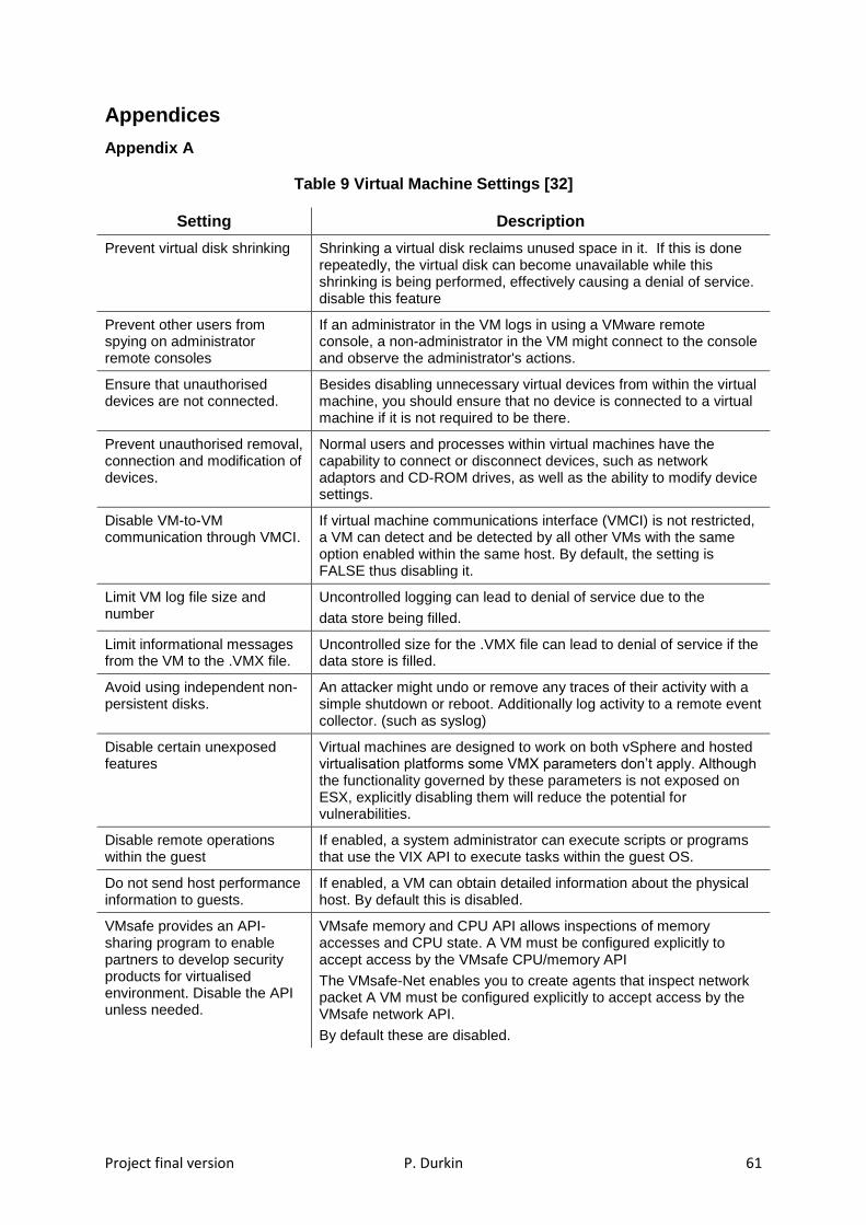
Project final version P. Durkin 61
Appendices
Appendix A
Table 9 Virtual Machine Settings [32]
Setting Description
Prevent virtual disk shrinking Shrinking a virtual disk reclaims unused space in it. If this is done repeatedly, the virtual disk can become unavailable while this shrinking is being performed, effectively causing a denial of service. disable this feature
Prevent other users from spying on administrator remote consoles
If an administrator in the VM logs in using a VMware remote console, a non-administrator in the VM might connect to the console and observe the administrator's actions.
Ensure that unauthorised devices are not connected.
Besides disabling unnecessary virtual devices from within the virtual machine, you should ensure that no device is connected to a virtual machine if it is not required to be there.
Prevent unauthorised removal, connection and modification of devices.
Normal users and processes within virtual machines have the capability to connect or disconnect devices, such as network adaptors and CD-ROM drives, as well as the ability to modify device settings.
Disable VM-to-VM communication through VMCI.
If virtual machine communications interface (VMCI) is not restricted, a VM can detect and be detected by all other VMs with the same option enabled within the same host. By default, the setting is FALSE thus disabling it.
Limit VM log file size and number
Uncontrolled logging can lead to denial of service due to the
data store being filled.
Limit informational messages from the VM to the .VMX file.
Uncontrolled size for the .VMX file can lead to denial of service if the data store is filled.
Avoid using independent non-persistent disks.
An attacker might undo or remove any traces of their activity with a simple shutdown or reboot. Additionally log activity to a remote event collector. (such as syslog)
Disable certain unexposed features
Virtual machines are designed to work on both vSphere and hosted virtualisation platforms some VMX parameters don’t apply. Although the functionality governed by these parameters is not exposed on ESX, explicitly disabling them will reduce the potential for vulnerabilities.
Disable remote operations within the guest
If enabled, a system administrator can execute scripts or programs that use the VIX API to execute tasks within the guest OS.
Do not send host performance information to guests.
If enabled, a VM can obtain detailed information about the physical host. By default this is disabled.
VMsafe provides an API-sharing program to enable partners to develop security products for virtualised environment. Disable the API unless needed.
VMsafe memory and CPU API allows inspections of memory accesses and CPU state. A VM must be configured explicitly to accept access by the VMsafe CPU/memory API
The VMsafe-Net enables you to create agents that inspect network packet A VM must be configured explicitly to accept access by the VMsafe network API.
By default these are disabled.

Project final version P. Durkin 62
Appendix B
Table 10 Virtual Network Settings [42]
Configuration Description
Ensure that vSphere management traffic is on a restricted network.
The vSphere management network provides access to the vSphere management interface on each component. Any remote attack would most likely begin with gaining entry to this network. The vSphere management interfaces include:
Service console interface on ESXi
Management VMkernel interface on ESXi
Strictly control access to management network.
The management network should be protected at the security level of the most secure virtual machine running on a host.
Ensure that IP-based storage traffic is isolated.
Virtual machines might share virtual switches and VLANs with the IP-based storage configurations. IP-based storage includes:
iSCSI
NFS
This type of configuration might expose IP-based storage traffic to unauthorised virtual machine users.
Ensure that vMotion traffic is isolated.
vMotion information is transmitted in plain text. Ensure that vMotion traffic is separate from production traffic on an isolated network.
Ensure that there are no unused ports on a distributed vSwitch port group
The number of ports in a distributed port group can be adjusted to exactly match the number of VMs assigned to that port group.
Ensure that the ‘MAC Address Change’ policy is set to reject.
To protect against MAC impersonation, this option should be set to reject, ensuring that the virtual switch does not honour requests to change the effective MAC address to anything other than the initial MAC address.
Ensure that the “Forged Transmits” policy is set to reject.
Forged transmissions is set to accept by default. This means the virtual switch does not compare the source and effective MAC addresses. To protect against MAC address impersonation, all vSwitches should have forged transmissions set to reject.
Ensure that the “Promiscuous Mode” policy is set to reject.
Promiscuous mode is disabled by default on the ESXi Server, and this is the recommended setting. If enabled all virtual machines connected to the vSwitch have the potential of reading all packets across that network.
Ensure that physical switch ports are configured with spanning tree disabled.
The physical network adaptors must have spanning tree disabled or port fast configured for external switches, because VMware virtual switches do not support Spanning Tree Protocol (STP).
Ensure that VLAN trunk links are connected only to physical switch ports that function as trunk links.
If the physical switch is not properly configured, frames with the VLAN 802.1q header would be forwarded to a switch not expecting their arrival. This may lead to undesirable consequences, including frames being dropped or misdirected.

Project final version P. Durkin 63
Appendix C
Table 11 PCI Requirement to VMware mapping [41]
PCI DSS Req
Description VMware Product
1.1 Establish firewall and router configuration standards vShield
2.1 Always change vendor-supplied defaults before installing a system on the network, including but not limited to passwords, simple network management protocol (SNMP) community strings, and elimination of unnecessary accounts.
vCenter Configuration Manager
2.2
Develop configuration standards for all system components. Assure that these standards address all known security vulnerabilities and are consistent with industry-accepted system hardening standards. Sources of industry-accepted system hardening standards may include, but are not limited to: Center for Internet Security (CIS) International Organization for Standardization (ISO) SysAdmin Audit Network Security (SANS) National Institute of Standards Technology (NIST)
vSphere Host Profiles vSphere VM Templates vCenter Configuration Manager
5.1
Deploy anti-virus software on all systems commonly affected by malicious software (particularly personal computers and servers).
vShield
6.1
Ensure that all system components and software are protected from known vulnerabilities by having the latest vendor supplied security patches installed. Install critical security patches within one month of release.
vCenter Configuration Manager vCenter Update Manager
6.2
Establish a process to identify and assign a risk ranking to newly discovered security vulnerabilities.
vCenter Configuration Manager vCenter Update Manager
7 Restrict access to cardholder data by business need to know vCenter Server
8.1
Assign all users a unique ID before allowing them to access system components or cardholder data.
vCenter Configuration Manager vCenter Server ESXi
10.1
Establish a process for linking all access to system components (especially access done with administrative privileges such as root) to each individual user.
vCenter Configuration Manager vCenter Server vShield
10.2
Implement automated audit trails for all system components.
vCenter Server vCenter Configuration Manager
11.5
Deploy file-integrity monitoring tools to alert personnel to unauthorized modification of critical system files, configuration files, or content files; and configure the software to perform critical file comparisons at least weekly.
vCenter Configuration Manager