canada -...
TRANSCRIPT

An Internet-Based Searchable Repository for DEVS Models and their Experimental
Frames
By
Rachid Chreyh
A thesis Submitted to
The Faculty of Graduate Studies and Research
In Partial Fulfillment of the requirements of the degree of
Master of Applied Science
Ottawa-Carleton Institute for Electrical and Computer Engineering
Department of Systems and Computer Engineering
Carleton University
Ottawa, Ontario
Canada
©Copyright 2009, Rachid Chreyh

ii
iii
ABSTRACT
The development of simulation models for complex systems can be difficult and time-
consuming; therefore, model reuse is of high value to model designers. To be able to
reuse modeling components it is important to know the context within which a given
component was developed. Experimental Frames are useful for capturing this context.
DEVS is a formal M&S framework that supports a hierarchical and modular development
of models. This work presents an architecture for an internet based repository of re-usable
DEVS models and their Experimental Frames. The proposed architecture uses
Experimental Frames to capture the context for the models and allow the sharing of
DEVS experiments. It specifies the storage entities required for such a repository,
including their contents and relationships; it allows for an ‘open source’ repository of
DEVS models and experiments to be built; and it presents a small step towards enabling
collaboration between different DEVS simulation tools.

iv
ACKNOWLEDGEMENTS
First of all, I thank God the almighty for giving me guidance and the ability and patience
to complete this research.
I would like to gratefully acknowledge the support of my supervisor, Dr. Gabriel Wainer,
who guided my research and helped shape it. His constant support, kindness, and patience
were very important in allowing the successful completion of this work.
I would also like to thank my parents, grandmother, and siblings for giving me the
strength to complete this work. This work would not have been possible without their
constant encouragement and support.
Finally, I would like to thank my wife, Reem, for her constant support and
encouragement during my work on this research. Her understanding and endless patience
throughout the course of my research were instrumental in allowing me to successfully
complete this work. I dedicate this work to her.

v
Table of Contents
ABSTRACT................................ ................................ ................................ ................................ ................ III
LIST OF TABLES ................................ ................................ ................................ ................................ .... VII
LIST OF FIGURES ................................ ................................ ................................ ................................ VIII
CHAPTER 1: INTRODUCTION................................ ................................ ................................ ......... 1
1.1 CONTRIBUTION ................................ ................................ ................................ ................................ 4 1.2 THESIS ORGANIZATION................................ ................................ ................................ .................... 7
CHAPTER 2: REVIEW OF THE STATE OF THE ART ................................ ................................ .9
2.1 THE DEVS FORMALISM................................ ................................ ................................ ................... 9 2.2 THE EXPERIMENTAL FRAME ................................ ................................ ................................ .......... 15 2.3 REUSABLE MODELLING COMPONENTS AND REUSABLE MODEL LIBRARIES................................ ...19 2.4 DEVS-BASED SIMULATION TOOLKITS ................................ ................................ .......................... 23
CHAPTER 3: PROBLEM STATEMENT................................ ................................ ......................... 26
CHAPTER 4: ARCHITECTURE OF THE REPOSITORY ................................ ........................... 31
4.1 THE STORAGE ENGINE ................................ ................................ ................................ ................... 33 4.2 THE ENTITIES STORED IN THE REPOSITORY ................................ ................................ ................... 35
4.2.1 Atomic and Coupled DEVS Models................................ ................................ ....................... 37 4.2.2 Experimental Frames ................................ ................................ ................................ ............ 40 4.2.3 Experiments................................ ................................ ................................ ........................... 43 4.2.4 Experimental Results................................ ................................ ................................ ............. 46
4.3 SUMMARY................................ ................................ ................................ ................................ ...... 47
CHAPTER 5: THE CD++ REPOSITORY - SOFTWARE ARCHITECTURE ............................ 49
5.1 OVERVIEW OF THE CD++ REPOSITORY SOFTWARE ARCHITECTURE................................ .............. 49 5.2 THE CD++ REPOSITORY BUSINESS OBJECTS ................................ ................................ ................. 52
5.2.1 Model Class Methods ................................ ................................ ................................ ............ 55 5.2.2 CoupledModel Class Methods................................ ................................ ............................... 56 5.2.3 Experiment Class Methods................................ ................................ ................................ ....57 5.2.4 ExperimentalResults Class Methods ................................ ................................ ..................... 57 5.2.5 Methods for all Business Object Classes................................ ................................ ............... 58
5.3 HIBERNATE AND OBJECT-RELATIONAL MAPPING................................ ................................ .......... 58 5.3.1 Introduction to Hibernate................................ ................................ ................................ ...... 59 5.3.2 Mapping CD++ Repository Business Objects to Database Tables ................................ ...... 63
5.4 MORE SOFTWARE DETAILS................................ ................................ ................................ ............ 66
CHAPTER 6: CD ++ REPOSITORY -THE CLIENT APPLICATION ................................ ........ 67
6.1 UPLOADING MODELS TO THE REPOSITORY ................................ ................................ .................... 67 6.1.1 The Model Definition (.ma) File Structure ................................ ................................ ............ 68 6.1.2 Automatic Detection of Model Kind, Structure, Name and Conflicts ................................ ....70 6.1.3 Collection of User Entered Data ................................ ................................ ........................... 73
6.2 UPLOADING EXPERIMENTAL FRAMES, EXPERIMENTS AND EXPERIMENTAL RESULTS ................... 75 6.3 SEARCHING AND DOWNLOADING MODELS AND THEIR EXPERIMENTS ................................ ........... 79
6.3.1 Searching for and Downloading Models ................................ ................................ ............... 80 6.3.2 Searching for and Downloading Experiments ................................ ................................ ...... 86
6.4 EDITING MODELS AND EXPERIMENTS................................ ................................ ............................ 89
CHAPTER 7: TESTING THE CD++ REPOSITORY ................................ ................................ .....92
CHAPTER 8: CONCLUSION AND FUTURE WORK................................ ................................ ...98
8.1 FUTURE WORK ................................ ................................ ................................ .............................. 99

vi
REFERENCES................................ ................................ ................................ ................................ .......... 101
APPENDIX-A: CD++ REPOSITORY SOFTWARE DETAILS................................ ......................... 106

vii
List of Tables
Table 1: Table of Model Zip Files Used During Testing ............................................. 93
Table 2: Tests and Results for Model-Based Operations ............................................ 95
Table 3: Tests and Results for Experiment-Based Operations................................... 96

viii
List of Figures
Figure 1: Definition of an Atomic DEVS Model [2]..................................................... 11
Figure 2: Structure of a Coupled DEVS Model ........................................................... 13
Figure 3: Modeling and Simulation Framework [10] [3] ............................................. 17
Figure 4: Experimental Frame System Specification [3] [10]...................................... 18
Figure 5: Repository Storage Architecture .................................................................. 34
Figure 6: Structure of a Stored DEVS Coupled Model ............................................... 40
Figure 7: Structure of a Stored DEVS Coupled Model ............................................... 43
Figure 8: CD++ Repository Software Architecture ..................................................... 51
Figure 9: CD++ Repository Business Objects Class Diagram .................................... 53
Figure 10: A High Level View of the Hibernate Architecture .................................... 60
Figure 11: Sample Hibernate Mapping File ................................................................. 64
Figure 12: CD++ Repository Relational Database Tables. ......................................... 66
Figure 13: Sample Atomic and Coupled (.ma) Files .................................................... 69
Figure 14: Atomic Model Upload Window Screenshot – Part1.................................. 74
Figure 15: Atomic Model Upload Window Screenshot – Part2.................................. 75
Figure 16: Event Based Experiment Upload Window Screenshot ............................. 77
Figure 17: Model Based Experiment Upload Window Screenshot ............................ 78
Figure 18: Experimental Results Upload Window Screenshot................................... 79
Figure 19: Model Search Window Screenshot ............................................................. 81

ix
Figure 20: Search Results Window Screenshot............................................................ 82
Figure 21: Download Window Screenshot.................................................................... 85
Figure 22: Experiment Search Window Screenshot .................................................... 87
Figure 23: Experiment Download Window Screenshot .............................................. 89
Figure 24: Concurrent editing of Models Test ............................................................. 97
Figure 25: Concurrent Upload of Models with Same Name Test .............................. 97
Figure 26: The gui.upload Java Package Structure................................................... 113
Figure 27: The gui.download java Package Structure .............................................. 118

1
Chapter 1: Introduction
In the field of software engineering, the concept of creating reusable software
components is of great importance to the reliability, maintainability and to reducing the
development costs of the software [1]. For instance, object-oriented methodologies and
programming languages have been developed in part to support this concept of
reusability. Using these methodologies and languages, libraries of reusable components
can be created and documented so that software application developers can use them in
the future. For example, one can find a vast amount of Java packages that can be re-used
by Java programmers to build new applications. Having reusable components means that
a given component is designed, developed and tested only once; it is then kept with other
components in a special library such that developers can reuse it in the future. Software
development teams who make use of reusable components in their applications will
benefit from the reduction in development cost (because the reusable components are
already developed). They will also benefit from the fact that the reusable components are
most likely very reliable (since any bugs would most probably have been fixed during the
first application’s testing cycle). Finally, the software will be easier to maintain because
at least some developers are likely to be familiar with the some of the reusable
components if they have used them before.
In the field of computer based Modeling and Simulation (M&S), the same benefits exist
through the creation of reusable simulation models. The Discrete Event System
Specification (DEVS) [2] can provide these benefits. DEVS is a formalism for the
modeling and simulation of discrete event systems that provides a framework for the

2
creation of hierarchical and modular simulation models. This hierarchical and modular
approach to model creation allows models to be independently tested and reused thus
enhancing reliability, maintainability and reducing the effort required for model
development and testing. In addition to the hierarchical and modular nature of DEVS
models, the DEVS architecture separates the model from the simulator, thus allowing the
execution of a given DEVS model on different simulator implementations [2].
Creating a DEVS model involves examining the system to be modeled (the source
system) through an “Experimental Frame”. An Experimental Frame (EF) is a
specification of the conditions under which a system is observed or experimented with
[2]. The Experimental Frame defines the data being collected and the conditions under
which the source system is being observed; in other words, it defines the context within
which the source system is being observed. A DEVS model thus aims to approximate the
behaviour of the source system within the parameters set by the Experimental Frame.
When a model is built, a DEVS simulator can be used to execute the model to produce its
intended outputs. The validity of a DEVS simulation model is closely related to the
parameters set by the experimental frame; in other words, a model of a source system is
only valid in the context for which the model was built.
The main motivation for this work is the desire to share DEVS models between different
users and the great benefits that this brings to the modelling process. As will be discussed
in later chapters, there are currently many DEVS tools in existence, but none provide a
means for sharing the DEVS models developed by the users of these tools. As will also

3
be discussed in later chapters, the model libraries in existence today are not suitable for
sharing DEVS models in a way that makes them publicly available. This ability to share
DEVS models necessarily promotes DEVS model reuse. Reuse of DEVS modelling
components greatly reduces the time and effort required when modelling complex
systems. This is because the availability of existing modular DEVS components that can
be “connected” together into more and more complex models means that, at least in part,
the complex system can be modelled by connecting the appropriate reusable DEVS
components together, thus reducing the effort and time required to model the system. A
second closely related motivation for this work is the desire to share the context of use
information about the shared DEVS models. Since the model of any real system is only
valid within the context for which the model was built [3], sharing this context
information is essential in order to be able to properly reuse DEVS models. As will be
shown in later chapters, many of the existing model libraries do not provide the context
of use information for the stored models. A third related motivation is the desire to also
share the experiments that were used to verify the correctness of the DEVS models.
These experiments can be difficult and time consuming to develop, and being able to
share them makes re-using the models that much easier; in addition, the availability of
these experiments provides confidence in the correctness of the models for which they
were built. As will be shown in later chapters, none of the existing model libraries
includes the concept of sharing the model’s experiments. The final motivating factor for
this work is that the increasing complexity of the systems that are being modeled and the
subsequent increase in the geographical separation between model design teams working
with the same design data has created a need to share this design data over large

4
distances. As a result, there is a desire to be able to share all the previously mentioned
items between modellers located at different geographical locations. Consequently, the
goal of this work is to develop an architecture for a system that firstly links together the
DEVS models, the context of use for those models, and the experiments used to verify
the models; and secondly enables the sharing of a DEVS model, its context information,
and its experiments over the internet.
1.1 Contribution
The inability to share DEVS models, their conceptual information (including the context
of use), and their experiments presents obstacles to the ability of modellers to apply the
desirable concept of model reuse. This work tries to provide a solution to this problem by
developing an architecture for a DEVS model library that can hold all of this information
about the DEVS models and is accessible over the internet. As will be shown in later
chapters, our research yielded no systems or architectures in existence today that provide
such information about models and that can be publicly available. Although there are
many DEVS simulation tools in existence today, none of them provide a means for
sharing DEVS models between users. In addition, many of the model libraries in
existence are either specialized for modelling certain systems, or concentrate on creating
modular components to facilitate model re-use (which is something that automatically
exists for DEVS models), or they do not hold all the required context of use and
experiment information. Importantly, none of the mode libraries in existence today is
capable of storing, along with the models, a set of experiments that can be run for them.

5
An important contribution of this work is the idea of storing the Experimental Frame
along with the DEVS models. The EF holds information about the context of use for the
model to which it belongs, as well as containing links to the experiments that can be run
on the model. This enables the sharing of the models and their experiments among
modellers. In addition, as will be described in later chapters, the proposed architecture
supports the reuse of the experiments by different DEVS models, meaning that a given
experiment may equally be applicable to more than one DEVS model, and thus be
‘linked’ to all of them.
A second contribution of this work is that it specifies the information that needs to be
stored for each entity kept in the repository. The main storage entities discussed in this
work are the Models, Experimental Frames, Experiments, and Experimental Results.
From a high-level view, one can easily talk about storing these entities in a repository; a
closer look, however, reveals that there are details regarding what exact information
needs to be stored for each entity. Each stored entity requires its own specific descriptive
information and may require the storage of certain files for example. In addition, the
relationships between these entities need to be represented in a manner that allows storing
them in the repository. This work provides a solution to these problems.
A third contribution of this work is the creation of an architecture that supports an “Open
Source” repository of DEVS models and experiments. Our research shows that at this
time there are no such “Open Source” model repositories in existence. The ‘open source’

6
concept means that modellers can use an internet connection to upload and download
DEVS modeling components and experiments to/from this repository. A user looking for
DEVS models of ATM machines, for example, can search this repository and download
what they need. Similarly, any user can add models and/or experiments to this repository
with no need for a ‘librarian’ to interfere.
Another contribution of this work is that it provides a small step in the direction of
allowing collaboration among users of different DEVS tools. While this work is not
directly concerned with solving the problem of interoperability between different DEVS
simulation tools, providing a repository that enables the sharing of DEVS models and
experiments is a small step that is required to enable users with different tools to share
their models once the other obstacles to interoperability are solved.
Finally, a prototype application, the CD++ Repository, was built based on the proposed
architecture to prove its effectiveness. There are many different DEVS Modeling and
Simulation platforms in existence today. In this work, the CD++ Builder platform is the
one for which the prototype repository application is developed. The CD++ Builder
toolkit [4] is built as a plug-in for the Eclipse IDE. It enables the users to develop DEVS
and Cell-DEVS models and run their simulations in a convenient and practical
environment. The CD++ Repository application was built to work with and be part of the
CD++ Builder toolkit. The CD++ Repository is composed of two main parts: an Internet
based database server and a client application. The database contains the stored entities
(Models, EF, Experiments, and Experimental Results) and their relationships. The client

7
application is embedded within the CD++ Builder toolkit in Eclipse and is used by a
modeller to either upload, or search for and download the desired DEVS models and EF
or the desired experiments or experimental results.
On a final note, a paper [5] based on the work in this thesis has been written and
presented in the SpringSim’09 conference in San Diego California. In addition, a paper
[6] on Cell-DEVS models for fire spreading analysis has been written and presented in
the seventh international conference on cellular automata for research and industry in
Perpignan, France.
1.2 Thesis Organization
The rest of this Thesis is organized as follows:
Chapter 2 introduces the Discrete Event System Specification (DEVS) and the Cell-
DEVS formalisms. A formalism for defining Experimental Frameworks is also
introduced. Then several works discussing reusable modelling components and model
libraries are presented. Finally, a brief survey of existing DEVS simulation toolkits is
presented.
Chapter 3 presents the problems that this thesis is concerned with solving. It then goes on
to describe how the existing model libraries introduced in the previous chapter are not
suited to solving the problem at hand. Finally, it presents a brief description of how these
8
problems are solved by the proposed repository’s design.
Chapter 4 describes the proposed architecture for the repository. The storage engine is
described, then the storage entities that are used to store the information are described in
detail. This chapter also illustrates how the relationships between these entities are stored.
Chapter 5 describes the software architecture of the CD++ Repository application, a
prototype application that implements the proposed architecture. It starts with an
overview of the architecture, and then proceeds to describe the business objects and their
mapping to database tables.
Chapter 6 describes the features and capabilities of the CD++ Repository’s client
application in terms of uploading, searching, downloading, and editing the stored models
and experiments.
Chapter 7 describes the testing that was performed on the CD++ Repository by using it to
store, retrieve and edit a number of CD++ DEVS models selected from a collection of
existing models.
Chapter 8 presents the main conclusions of the thesis, and present possible future work.

9
Chapter 2: Review of the State of the Art
This chapter reviews the state-of-the-art in the modelling and simulation field,
specifically in aspects that are useful in building libraries of reusable DEVS components.
The original DEVS formalism is first introduced followed by the Cell-DEVS formalism.
Then the Experimental Frame concept is discussed as a way to capture the context within
which a model is designed; then a formalism of the Experimental Frame is given. Then,
the hierarchical models library (HMLib [7]) is introduced as an example of an existing
models library. Finally, a brief survey of existing DEVS simulation toolkits is given with
emphasis on the CD++ Builder Toolkit, and the lack of a model’s database feature in
other toolkits.
2.1 The DEVS Formalism
The Discrete Event System Specification (DEVS) formalism [2] provides a sound and
formal M&S framework. It also supports the hierarchical and modular development of
models. Using DEVS a system can be described using atomic and coupled DEVS
models. The atomic models are the basic building block of any DEVS model. They
define the behavior of a component in the system. The coupled models are structural in
nature in that they are composed of an interconnection of other atomic and/or coupled
models.
The following is the formal definition of an Atomic model [2]:
M = <X, S, Y, δint, δext, λ, ta>
10
Where
X is the set of external input events;
S is the set of sequential states;
Y is the set of outputs;
δint: S → S is the internal transition function;
δext: Q × X → S is the external transition function, where
Q = {(s,e) | s ε S , 0 ≤ e ≤ ta(s) } is the total state set where e is the elapsed time
since the last transition.
λ: S → Y is the output function;
ta: S → R0 → ∞ is the time advance function;
The behaviour of an Atomic DEVS model can be described as follows. A model starts at
a given state, s, and will remain in that state for an amount of time defined by the time
advance function ta(s). If during this time an external event is received at one of the input
ports, the external transition function is executed to determine the new state of the model.
If no external events are received and the time defined by ta(s) elapses then the output
function λ is executed the resulting output value is presented at the output port, then the
internal transition function is executed to determine the next state of the model. This
behaviour can be visualized by the diagram in Figure 1 [2] :

11
Figure 1: Definition of an Atomic DEVS Model [2]
The formal definition of the DEVS coupled model on the other hand is [2]:
CM = < X, Y, D, {Mi}, {Ii}, {Zij}, ς >
Where
X is the set of input events;
Y is the set of output events;
D is an index for the components of the coupled model;
i ε D, Mi is a basic DEVS model, defined by
Mc= < Ii, Xi, Si, Yi, δinti, δexti, ta >
{Ii} is the set of influencees of model i (that is, the models that can be influenced by
ttaa((ss)) ss
ss
yy
ss’’ == iinntt ss
xx
ss’’ == eexxtt ((ss,,ee,,xx))

12
outputs of model i);
{Zij} is a set where j Ii, Zij is the i to j translation function;
ς is the tie-breaking selector;
To elaborate on the above definition, a coupled model is composed of a number of basic
models “Mi”. Each model’s outputs are connected to the inputs of its influencee models
{Ii}. The Zij function translates the outputs from component i to the inputs of component
j, and thus defines the coupling of the inputs and outputs of the components. The tie-
breaking selector is needed because of the possibility that the internal transition function
of more than one component can occur at the same time. It defines an order over the
components so that only one will have its internal transition function trigger at any time.
Finally it is important to note the concept of closure under coupling, which basically
means that for every coupled DEVS model there is an equivalent atomic DEVS model.
This implies that the basic components that make up a given coupled model can
themselves be atomic or coupled models.
Figure 2 below illustrates the structure of a sample coupled DEVS model. As can be seen
the top model, Coupled Model #1 is composed of two child coupled models (Coupled
Model #2 and Coupled Model #3) and an atomic model (Atomic Model #6). The inputs
of the top model are coupled to the inputs of the two child coupled models, the outputs of
the child coupled models are coupled to the inputs of Atomic Model #6, and finally the
output from Atomic Model #6 is coupled to the output of the top model. Similarly, the

13
child coupled models are composed of child atomic models and the inputs and outputs of
the coupled models and their children are coupled as illustrated in Figure 2.
Figure 2: Structure of a Coupled DEVS Model
The Cell-DEVS formalism [8] is an extension to the DEVS formalism and is used to
model real life systems that can be represented as cell spaces. Under Cell-DEVS, each
cell in a cell space is represented as an atomic DEVS model. Each cell has input and
output ports that are connected to its neighbouring cells or other DEVS models outside
the cell space. The inputs to a cell can cause its state to change, in which case the new
state will be transmitted to the neighbouring cells. In addition, a delay mechanism in
each cell (transport delay or inertial delay) is used to delay the propagation of state
change events through the cell space and thus provides the modeller a means to define
complex temporal behaviour. The following is the formal definition of the Atomic Cell-
DEVS [8]:
Coupled Model #2
Atomic Model #1 Atomic Model #2
Coupled Model #3
Atomic Model #3
Atomic Model #4
Atomic Model #5
Atomic Model #6
Coupled Model #1 (Top Model)

14
TDC = < X, Y, I, S, θ, N, d, δint, δext, τ, λ, D >
X is the set of external input events;
Y is the set of external output events;
I represents the definition of the model’s modular interface;
S is the set of possible states for a given cell;
θ is the definition of the cell’s state variables
N is the set of values for the input events;
d is the delay of the cell;
δint is the internal transition function;
δext is the external transition function;
τ is the local computing function;
λ is the output function, and
D is the duration function.
Connecting the Atomic Cell-DEVS model together into a cell space produces a Coupled
Cell-DEVS model. This model can take any shape, and can form a 2-Dimensional or a 3-
Dimentional cell space. The borders of the cell space can be either wrapped, in which
case the cells at the border from one side of the cell space are considered neighbors to the
cells at the border on the opposite side of the cell-space, or non-wrapped, in which case
the border cells must have special rules defined by the modeler. The formal definition of
the Coupled Cell-DEVS is as follows [8]:

15
GCC = < Xlist, Ylist, I, X, Y, n, {t1,….,tn}, N, C, B, Z, select >
Xlist is the input coupling list;
Ylist is the output coupling list;
I represents the definition of the model’s modular interface;
X is the set of external input events;
Y is the set of external output events;
n is the dimension of the cell space;
{t1,….,tn}is the number of cells in each of the dimensions;
N is the neighborhood set;
C is the cell space;
B is the set of border cells;
Z is the translation function; and
select is the tie-breaking function;
2.2 The Experimental Frame
In the DEVS M&S field, the System-Model-Simulator view is a very well accepted
framework. It defines the relationships between the system, the model and the simulator:
the system is related to the model by the modeling relationship and the model is related to
the simulator by the simulation relationship. When a model is built for a system, the
system is studied within a given context to derive the specifications of the model.
Therefore, a model is valid only within this context and is meaningless without it [3]. It is

16
therefore important to capture the specifications of the context in which a system is
studied. It is generally agreed that the characterization of the context must explicitly state
the underlying objectives, assumptions, and constraints of the study [3].
The Experimental Frame (EF) concept has been introduced to capture the set of
circumstances under which a real system is to be observed, or capture the set of
circumstances under which a model is to be subjected to experimentation [2] [9] . This
makes the meaning of EF ambiguous in that it could mean different things within the
M&S process. In [10] the idea of a framework that takes into account the different
meanings of an EF was introduced. These ideas were formalized by the Context-Frame-
Experimentor framework and formalized by Traore and Muzy [3] . This framework,
shown in Figure 3, presents a clear distinction between the three levels of abstraction,
namely: the context through which a real system is being studied, the specification of this
context as an EF, and the implementation of this EF to execute on a simulator.

17
Figure 3: Modeling and Simulation Framework [10] [3]
As mentioned earlier the context within which a system is studied during the modelling
process is important to capture because the model is meaningless without its context. A
specification of the context would also make it possible to identify models that may be
relevant for re-use within a given context [3]. Using the framework of the experimental
frame described in Figure 3, Traore suggests that the context be formally described by the
EF. This formal specification of the EF is described below.
As shown in Figure 4, one can think of the EF as a circuit board with input and output
ports into which a source system or a model can be ‘plugged-in’. The EF itself can be a
complex combination of components with their own interconnections and inputs and
outputs. A simple example of an experimental frame is one made of three components, a
Source
System
Context
Model
Frame
Modeling
relation
Simulator
Experimenter
Simulation
relation

18
generator, acceptor, and transducer as presented in [3]. Note that these EF components
can be DEVS models in themselves. A subset of the inputs and outputs between the
model and the EF form an interface to which both the model and EF must adhere.
Figure 4: Experimental Frame System Specification [3] [10]
The formal definition of the EF is [3]:
EF =< T , IM , IE , OM , OE , ΩM , ΩE , ΩC , D , {Cd , d ε D},
CPIC, EICC, POCC, CEOC, CCC>,
Where
T is a time base;
IM is the set of Frame-to-Model input variables, the plug-in input set;
IE is the set of Frame input variables, the control input set;
OM is the set of Model -to-Frame output variables, the plug-in output set;
OE is a set of Frame output variables, the summary set;
Frame
Frame Components
CCC
IE
IM
CPIC
EICC
OM
POCC
CEOC
OE

19
ΩM is the set of admissible input segments for the plug-in component, the plug-in input
constraints set;
ΩE is the set of admissible input segments for the experimentation control, the control
input constraints set;
ΩC is the set of admissible output segments expected from the plug-in component, the
plug-in output constraints set;
D is a set of component names, the control components set;
Cd is a model for each d ε D;
CPIC is the Control-to-Plugin-Input coupling;
EICC is the External-Input-to-Control coupling;
POCC is the Plugin-Output-to-Control coupling;
CEOC is the Control-to-External-Output coupling;
CCC is the Control-to-Control coupling;
2.3 Reusable Modelling Components and Reusable Model Libraries
The use of re-usable components in the modeling and simulation field is of interest to
many researchers. In addition, the idea of creating a library of these reusable modeling
components is attractive to many researchers since such a library would greatly facilitate
the actual reuse of these components. In this section several research works in this area
are presented.

20
In [7] [11] [12] [13] the authors introduce an object-oriented architecture for the definition
of web-based hierarchical models libraries. This architecture is based on [12]: The notion
of being a generic library, the ability to manage abstraction and inheritance between
stored models, and the ability to access the library using web-based procedures. By being
a generic library the authors propose to store models in the library in what is called a
“context-out” format. When a model is extracted from the library it has to be converted to
its “context-in” format to be able to use it in a specific simulation environment. The
authors focus on structuring the models in the library according to their domains and the
abstraction levels. The domain refers to the theoretical domain of the stored models (for
example DEVS, VHDL ... etc). A subset of the domain is an application domain which
refers to the actual application domain for a given model (for example Microelectronics).
The abstraction level on the other hand refers to the amount of information contained in a
given model.
In [14] the authors are concerned with reducing the knowledge gap between the creators
of behaviour models (the analysts) and the users of those models (designers). This paper
focuses on proposing a meta-data representation to characterize behavioural models. This
meta-data gives the model users information such as the assumptions, limitations, and
context of the models. Based on this a prototype repository is presented to store the
models and the meta-data. The repository is envisioned as a store of behavioural models
from which model designers select a single model that is most appropriate for their
objectives, then they populate the model with their specific design parameters, and finally
they execute the model and evaluate the results, refining the parameters and re-executing

21
if needed.
In [15] the authors propose developing a library of reusable model fragments and models.
A large part of this paper is concerned with proposing a structure for the models that go
into the library. The proposed structure divides a models into three “viewpoints”, namely
a technical component viewpoint (e.g. a resistor), a physical concept viewpoint (e.g.
resistance, weight …etc.), and mathematical viewpoint. The library stores each of these
viewpoints separately in the library and a complete model is created by linking these
model fragments together. Complete models can also be stored in the library. In addition,
to facilitate the management and use of models, the documentation for them is stored,
they are categorized into a taxonomy structure, and their quality information is stored.
Building a model using this library involves specifying all three viewpoints for it and
adding a model to the library involves a “library manager” creating links to it so that
future users can find it. The library does not store actual model files directly but uses a
“generic description language” that is then exported to the format of the simulation tool
being used (such as Matlab, Simulink ... etc). The paper does not specify this language or
how it is exported.
In [16] the authors present a very general wish-list of what their envisioned repository
would do with no details of design or architecture. The repository is envisioned to contain
models from various categories such as networking models, discrete simulation models,
linear and non-linear models… etc. The repository is intended for use in higher education
setting where students and faculty could use the models to apply knowledge learned in

22
courses to real world problems. It is clear that at the time of publishing of this paper, the
authors had not yet designed the structure of the repository or the elements stored in it.
In [17] the author creates a collection (library) of reusable models and shows how they
can be used in the Visual Simulation Environment (VSE) for visual simulation of the
NCSTRL system. The paper demonstrates how the reusable components can be used to
create simulations for different configurations of the system without doing any code
changes. The paper however does not present an actual library architecture; but it refers
to the collection of nine re-usable models that were created as a library of re-usable
models.
In [18] the authors do not actually propose an architecture of a model library. This paper
simply takes a specific example, “the flow of jobs through a job shop”, and from it
extracts requirements information for each component of that example (this is
information specific to the example). Then the paper goes on to create a number of
database tables based on this information; thus, these tables are also very specific to the
example. Finally, a model builder is created which is capable of taking the “neutral’
information from the database and converting it into a simulation model that can be run.
The database tables created in this work are specific to an example and cannot be used as
a basis for a general model library.
In [19] the authors focus on using JavaBeans to create reusable simulation components.
23
This paper presents guidelines for building reusable component architectures and then
demonstrates the use of these guidelines through several component architectures. The
paper is not concerned with building a library in which to store the reusable components.
There are also the following simulation platforms that should be mentioned here, namely
NS-2 [20], OMNeT++ [21], and OPNET Modeler [22]. These are all simulator platforms
that are focused on the networking field. They provide users with a collection of network
components from which users can build the network to be simulated. They also provide
the ability to create network components that can then be shared with other users.
OMNeT++ for example currently has on their website a list of 41 “Supported Models”
and 24 “Contributed Models”. NS-2 also has a website with a set of links to “modules”
contributed by users. Being a corporate product, OPNET Modeller comes with a large
suite of components that enable users to model many types of networks. Other than the
listings on the websites, there does not seem to be a publicly available repository of
models that is capable of managing the stored models.
2.4 DEVS-Based Simulation Toolkits
The CD++ Builder toolkit is one of many different implementations of tools that enable
modeling and simulation based on the DEVS formalism. Most of these tools are
concerned with providing an engine to run DEVS simulations on and with providing a
library of classes upon which modelers can build their DEVS models. These tools do not
provide a way to store DEVS models for future reuse.

24
A list of some of the other DEVS simulation tools is available on the internet at [23]. The
following is a brief list of a selection of some of the tools listed on this website with a
short description of each. It is worth noting that none of these toolkits has capabilities
similar to the capabilities of the CD++ Repository, which will be introduced in later
chapters.
ADEVS [24]: This tool provides a C++ class library based on the Parallel DEVS
and DSDEVS formalisms which developers can use to build their own models. It
includes support for standard, sequential simulation and conservative, parallel
simulation on shared memory machines with POSIX threads. [23]
DEVS/C++ [25]: This is a DEVS simulation environment based on the Parallel-
DEVS formalism and implemented in the C++ language. [23]
DEVS/HLA [26]: This is a High Level Architecture (HLA) compliant DEVS
environment. It was developed to demonstrate how an HLA-compliant DEVS
environment can significantly improve the performance of large-scale distributed
modeling and simulation exercises. [23]
DEVSJAVA [27]: This is a DEVS modeling and simulation environment
implemented in JAVA. It supports parallel execution on a uni-processor and
supports higher-level, application specific modeling. [23]
JDEVS [28]: This is a Java based DEVS modeling and simulation environment
that enables general purpose, object oriented, component based, GIS connected,
visual simulation model development and execution. [23]

25
SimBeans [29]: This allows component based DEVS modeling and simulation on
the basis of Java and JavaBeans. [23]

26
Chapter 3: Problem Statement
The DEVS formalism provides a framework for building modular and hierarchical
simulation models. This is a first and important step towards the goal of sharing and
reusing modeling components. However, one of the main problems that stand in the way
of the reuse of DEVS models is the inability to share DEVS models between model
designers in an easy and correct fashion. A mechanism is needed by which model
designers can access and contribute DEVS models to a pool of shared models.
Nevertheless, the ability to access other designers’ DEVS models alone is not enough to
enable reuse. This is because a model is useless without the knowledge of how it can be
used and in what context. Therefore, a mechanism is also needed to enable sharing of the
conceptual information describing the DEVS models; this information must include
information about the context within which the model was intended to be used. In
addition, model designers could have created a number of experiments to test their DEVS
models. Sharing these experiments and their results provides other users with valuable
information about the workings of the DEVS model as well as a measure of confidence in
the accuracy of the DEVS model. The ability to rerun an experiment and reproduce the
same simulation results and the availability of the simulation logs to new users are
important to ensure fidelity of the models especially in a publicly available system where
anyone can contribute models and experiments. Therefore, a mechanism that allows
sharing and reuse of these experiments and experimental results is also required.
It follows that the aim of this work is to develop a mechanism that facilitates the sharing
and reuse of DEVS models, their experiments, and their experimental results. Chapter 2

27
described a number of previous research efforts that aimed at creating repositories of
reusable simulation components. Nevertheless, each of these research efforts emphasised
a specific problem and presented their version of a model library as a solution to it. As
will be shown in the next few paragraphs, none of these solutions provides all of the
elements desired in a DEVS model repository.
To start, the works presented in [16], [17], [18], and [19] do not present an architecture of
a model repository that can be used to store and retrieve modelling components. Instead
[16] is a brief paper with a very general description of the author’s vision of what a
model repository would do. In [17], [18], and [19] on the other hand the author’s use the
term ‘library’ to refer to the collection of models that they are presenting in their works,
and that could in themselves be reused, but do not present an infrastructure to manage
these models. Thus, these works are not suitable to solve the problem at hand.
Next, the simulation platforms NS-2, OMNeT, and OPNET Modeler discussed in
Chapter 2 are focused on the networking field and thus provide components that are
primarily for modelling of networks. In addition, they do not have a repository of models
as such; instead, OPNET Modeler provides its models as part of a package when users
purchase the product and thus its models are not open for public use, while NS-2 and
OMNeT provide listings of their models on their web pages. This makes locating models
of interest to a user a difficult task especially since no “context of use” information is
provided up front. Furthermore, no mechanism is provided for sharing experiments and
experimental results. Thus, the libraries of models provided by these platforms are not

28
suited for use as a publicly available repository of models and experiments.
Next, the authors of [15] present a structure for a library of reusable models. However a
main focus of this library is on assisting the user in the building of the low level details of
the modular components themselves (by specifying mathematical viewpoints, etc), which
complicates the process of using the library and is not necessary for a library of reusable
models. In addition, this library relies on a set of pre-existing technical components to use
for building other components, meaning that the library is built for a specific field and is
not general enough to be used for models from different fields. Furthermore, building and
maintaining the taxonomy structure of the technical components in the library requires a
modeller experienced in the specific field who can recognize the links between the
different components. This hinders the ability to add modelling components that could
conceivably be from any modelling field (since you would need experienced modellers in
every field to maintain the library). As a final note, the library does not provide a means
for storing and linking the experiments and experimental results pertaining to the stored
models. Thus, this model library is also not suited for use as a publicly available
repository of models and experiments.
Next, the authors of [14] propose a meta-data representation to describe the behavioural
models’ assumptions, limitations, accuracy and context. Then they propose a prototype
repository to store the models and their meta-data. This sounds very promising except
that it does not allow the storage of a hierarchy of linked models (such as coupled DEVS
models). It assumes that the stored models are in one piece and are not built from other
smaller modular components. This will not work for DEVS models since they are

29
hierarchical in nature and a Coupled DEVS model is ultimately made up of child Atomic
models. When a coupled model is stored in a repository all the child atomic models
should therefore become part of the repository as well, which is not the case here. As a
result, this repository would not be very useful for storing coupled DEVS models. In
addition, the repository proposed in this paper does not contain a mechanism for storing
and reusing experiments and experimental results. Having these experiments and
experimental results is important for ensuring model fidelity in a publicly available
repository. Thus, this model library is also not suited for use as a publicly available
repository of models and experiments.
Finally, in [7] [11] [12] [13] the authors introduce an architecture for creating web-based
hierarchical model libraries. The library proposed in these papers is capable of managing
inheritance and abstraction links between stored models. The library can be consulted to
find the model of interest, however there does not seem to be a facility to search the
library. Instead the models are categorized according to domains and sub-domains and
the abstraction levels. In addition, other than the domains and the abstraction links, there
dose not seem to be descriptive or context of use information for the stored models.
Finally, the repository proposed in this paper does not contain a mechanism for storing
and reusing experiments and experimental results. Thus, this model library is also not
suited for use as a publicly available repository of models and experiments.
As a result, none of the existing solutions is suitable to solve the problem of model
sharing and reuse. In this work, we define new mechanisms for accessing DEVS models,
30
their context of use information, their experiments and experimental results. We propose
new methods for linking the stored items together as appropriate (for example linking a
model to its experiments). The prototype software application is publicly available on the
internet such that any user can add to or download items from it following an open-
source based approach. Finally, it provides information (including context-of-use
information) to enable users to locate models and/or experiments of interest to them.

31
Chapter 4: Architecture of the Repository
The architecture presented in this chapter can be used to implement a repository for any
of the DEVS tools in existence today. As discussed in Chapter 3, this work intends to
enable the creation of a repository of DEVS models that is capable of managing models,
experiments, experimental results and their conceptual information in such a way that
facilitates their reuse. The repository must be accessible from different geographical
locations enabling users to either contribute their DEVS models and/or experiments to the
repository, or search for and download the DEVS models and/or experiments from the
repository. The repository is to store the conceptual, descriptive, and context of use
information for each model in order to make possible the sharing of the models in a
useful way.
To achieve this, the repository design uses a client-server architecture (with all of the
information stored in a central database server that is accessible by the repository’s client
application over the Internet). The DEVS models are stored in the repository as atomic
and coupled entities each with their own descriptive information and model files. The
coupled entities are linked to their atomic/coupled sub-components thus preserving the
natural hierarchical structure of DEVS models, and enabling the efficient and modular
storage of the models. Each model entity is linked to an Experimental Frame (EF) entity
in the database. EF entities include information about the context of use for the linked
model, as well as any number of experiments that are applicable to that model. The
experiments are stored as entities of their own with their own descriptive information and
their own experiment files. This enables the linking of a given experiment to more than

32
one model thus enabling the re-use of the experiments. Experiments could be of two
types either “event-based” or ‘model-based”. Event-based experiments use a file to drive
the inputs of the model for the experiment, while model-based experiments use other
DEVS models as generators and transducers. In the case of model-based experiments, the
DEVS models used as generators and transducers are also linked to the experiment entity.
The last major entity stored in the database is the experimental results entity, which is
composed of descriptive information and files generated by a run of the experiment. The
experimental results are put into separate entities from the experiments because a given
experiment could be linked to more than one model; each experimental result is therefore
associated with a model-experiment pair. Other entities stored in the repository include
input/output and range entities used to specify the inputs and outputs of the EF (as per the
EF formalism presented in Chapter 2).
From a very high level, the proposed repository is comprised of two main components; a
server and a client component. The server component contains a central database
containing the models, their experimental frames, experiments, and experimental results.
The database is hosted on a computer connected to the internet that the client component
can connect to. The client component is responsible for querying the database and
presenting results to the user, as well as adding new entries into the database at the
request of the user.
The heart of this architecture is in the details regarding the stored entities. The next sub-
sections will take a closer look at the storage engine, explain the exact entities that it is

33
able to store, the information stored about each entity, and the relationships between the
stored entities.
4.1 The Storage Engine
In essence, the repository is a store of DEVS Models and their Experimental Frames
(which include the actual experiments). Therefore, at its core there is a storage engine
capable of storing and retrieving all of the relevant information. As with most other
database applications, a relational database management system (DBMS) was chosen as
the core of its storage solution. Relational databases are proven to be reliable and easily
support the tasks of querying and adding items. In addition to the relational database, the
storage engine uses an FTP server to store files related to the stored entities. Both the
database and FTP Servers reside on the same physical machine that is connected to the
internet. As shown in Figure 5, client machines that are connected to the internet can
connect to the Database and FTP servers in order to upload or download information.

34
Figure 5: Repository Storage Architecture
The Relational Database Server is the heart of the storage system since it holds all of the
information for all of the entities stored by repository. This includes all of the
relationships between all of these entities. The entities stored in the Relational Database
are Atomic Models, Coupled Models, Experimental Frames (including Experimental
Frame Inputs and Outputs, and Ranges), Experiments, and Experimental Results. A
detailed discussion of what these entities are actually composed of and what information
is stored for each is presented in the following sub-sections.
Each of the model entities as well as the experiment and experimental result entities may
have a number of files related to them. For example the Atomic Model may have a C++
program file (.cpp), a header file (.h), a model definition file (.ma), and a description
CD++ Client #1 CD++ Client #2 CD++ Client #3
CD++ Client #4
FTP SQL
Database
CD++ Server Machine
Internet

35
document (.doc); in fact this is the case for CD++ Atomic models as will be seen in later
chapters. These files are compressed into a (.zip) file and stored on the FTP server. Each
entity in the Relational database has a “pointer” to the (.zip) file that concerns it on the
FTP server. Thus, the FTP server can be seen as a dumb store of files, while the
Relational Database Server contains the information describing each entity and relating it
to the other entities in the system and to its (.zip) file on the FTP Server.
4.2 The Entities Stored in the Repository
The goal of this repository architecture is to enable sharing of DEVS models and
experiments among users. Therefore, the information pertaining to these models and
experiments has to be encapsulated and stored in the database. This leads to the creation
of the storage entities that have been mentioned in the previous section. In the following
paragraph, the rational behind deciding on these storage entities is presented.
It is clear that a model storage entity is required to store the DEVS model information;
more specifically however, in DEVS there are two basic types of models Atomic and
Coupled. Therefore, both atomic model and coupled model storage entities are required.
However, as mentioned earlier, a model without its context is meaningless; therefore an
entity is needed to hold the context of use information for the model. A look back at the
Experimental Frame idea presented in Chapter 2 leads to the creation of the Experimental
Frame (EF) storage entity. This entity will hold the information about the context within
which the model is valid. Each model entity has one EF entity linked to it. The next item

36
missing from the repository is the experiment. On first thought, one might be tempted to
include the experiment information within the EF entity. If that were done however, it
would not be possible to share experiments among different models. In a real life
scenario, experiments can in fact be reused to test different DEVS models; therefore, the
storage architecture should reflect the fact that a number of models can share one
experiment. As a result, an experiment storage entity is required to hold the experiments’
information. Then, these experiment entities can be linked to any number of EF entities to
represent the experiments that belong to each EF entity. The final missing item is the
experimental results. Experimental results are obtained by running a given experiment on
a given model, and thus by definition they refer to a model-experiment pair. As a result
an experimental results entity is needed to store information relating to them, this entity is
linked to both a model entity and an experiment entity.
The conceptual meaning of these entities is clear from the above discussion, but to give
an exact meaning to these entities one needs to specify what information is actually being
stored for each. What are the pieces of information that need to be stored by the
repository for each entity, and how can the relationships between all of these entities
stored? These questions are central to the creation of the repository. The following sub-
sections describe each of these entities in more detail, and answer the aforementioned
questions for each.

37
4.2.1 Atomic and Coupled DEVS Models
In general, DEVS models can be either Atomic or Coupled Models, with Cell-DEVS
models being a special case of the Coupled model. So far the DEVS models have been
discussed as abstract entities or as a mathematical formalism (as in Chapter 2), however
to be able to describe a DEVS model to a simulation tool the model is usually describe
programmatically via a computer program or some other format that a computer can
understand. Thus, for each model storage entity a number of files describing the model
should be stored. The exact files depend on the exact simulation tool for which the
repository is being designed. In addition, Atomic and Coupled models may require
different kinds of files. As an example, the CD++ Builder Toolkit represents an Atomic
Model with three files, the first two are the C++ class files (program (.cpp) and header
(.h) files), the last file is the model definition file (.ma) containing the coupling scheme
for the model as well as some other parameters. Coupled Models (including Cell-DEVS
models) on the other hand are described using only one file, the model definition file
(.ma). In this file a specially designed specification language allows the description of all
the components (sub-models) of the Coupled Model and allows the declaration of the
interconnections of the input and output ports of all of these sub-models. In addition to
these that are specific to the simulation tool, a file that contains a detailed description of
the model, a (.doc) file for example, is useful for users to understand the exact details of
the model, and is thus required for storage by the repository. To accommodate the fact
that each simulation tool has its own set of files that represent the models, the architecture
of the repository specifies that each model entity, be it atomic or coupled, should store a
pointer to a location on the FTP server where all the required files may be found. This

38
location may be a directory, a (.zip) file or any other convenient location.
In addition to files however, the model storage entity should also store some data
describing each model. This data describes the model in a way that is useful to a human
user so that when the user is presented with this data for a number of models, he/she can
quickly determine the model that interests them. The simplest example of such data is
giving a name to each model. There are many other candidate pieces of information that
can be stored with the models to more fully describe them. This information will be
referred to as the Model Data throughout this thesis. The Model Data is comprised of the
following pieces of information:
1. Model Name: This is a unique name generated by the repository software for
each model in the repository.
2. Domain: This is the domain under which the model can be categorized. Examples
are Telecommunications Equipment, Urban Traffic…. etc.
3. Title: Is a descriptive title for the model.
4. Acronym: Is the acronym for the model.
5. Brief Description: This is a short paragraph (less than 250 chars) describing the
model’s general characteristics.
6. Key Words: These are a few key words that are associated with the model, and
that can be useful when doing a search of the repository.
7. Developer Name: The name of the model’s developer.
8. Date Developed: The date the model was developed.

39
In the relational database, the model entity can be translated, roughly, into a database
table with the Model data comprising the majority of its columns. This allows the
repository the ability to search for models based on the information provided in the
Model Data. For example, a user can search for all models in the repository with a
Domain of “Telecommunications Equipment”, or for all models with the word “motor” in
their Title.
So far, the discussion of the DEVS models stored in the repository ignored the fact that,
by definition, Coupled DEVS models have ‘relationships’ with other models in the
database. As explained in Chapter 2, a Coupled Model is composed of a tree of other
‘child’ DEVS Models that could themselves be either Atomic or Coupled. This
hierarchical construction of Coupled DEVS models is one of the advantages of the DEVS
formalism. When a Coupled model is stored in a repository of models it could simply be
stored as one entity (a generic model entity as has been described so far) containing its
own files and all of its children’s files. However, by doing that one will lose the
advantage of the hierarchical construction built into the DEVS Coupled model.
Therefore, the proposed repository’s architecture maintains the hierarchical construction
of the Coupled models even while they are stored. This is done by creating separate
atomic model and coupled model entities that are basically copies of the model entity
described above. The coupled model entity can then be linked it to its tree of child model
entities in the repository. For example, suppose a Coupled model A is composed of the
two atomic models X and Y, and another Coupled model B is composed of Coupled

40
model A and Atomic model Z. Each of these models are stored separately in the
repository, with Model A linked to Models X and Y, and model B linked to models A
and Z (See Figure 6). In this case, when the repository is asked to retrieve model B for
download it is able to follow the links and retrieve all of model B’s child models, thus
retrieving all of the models in Figure 6.
Figure 6: Structure of a Stored DEVS Coupled Model
4.2.2 Experimental Frames
While storing the DEVS Models themselves is a major part of this work, an important
feature of it is the storage of an Experimental Frame for each stored Model. The
Experimental Frame storage entity must always be linked to one model entity in the
repository. The Experimental Frame entity should be able to store Experimental Frame
Data (analogous to the Model Data), should be linked to a set of experiment entities that
are related to the model (described in the next sub-section), and should contain other EF
information corresponding to the formal definition of the Experimental Frame (described
Coupled Model ‘B’
Coupled Model ‘A’ Atomic Model ‘Z’
Atomic Model ‘Y’ Atomic Model ‘X’

41
later in this section). Unlike the model entity, experimental frame entities do not have any
files associated with them. In the relational database, the EF entity can be represented as
a table with the Experimental Frame Data comprising most of its columns, and with links
to a model entity, and a number of experiment entities.
The Experimental Frame Data is the data used to describe the context within which a
given model is valid. This data is displayed to the user as part of a model’s descriptive
information to assist them in making a decision as to the usefulness of that model to
them. This data is comprised of the following pieces of information [3]:
1. Objectives: These are the objectives for which the model was built.
2. Assumptions: These are the assumptions made by the model designer when
designing this model.
3. Constraints: These are the constraints within which the model was designed to
operate.
As explained in Chapter 2 the experimental frame captures the context within which the
model operates. Any real life scenario can be seen from different angles and more than
one model can be created each having its own context (and thus its own Experimental
Frame Data). For example, a forest fire might be modeled with different objectives in
mind: one objective can be determining the rate of fire spread, while another objective
can be determining the amount of pollution caused by the fire. This leads to two different
models for the same scenario. Similarly, the assumptions and constraints can be different
for different models modeling the same real life system each from their own context. A

42
model’s Experimental Frame captures this information, and in the repository, it is stored
as the three pieces of data Objectives, Assumptions, and Constraints.
The final part making up the Experimental Frame entity is what is referred to here as the
other EF information. This information is composed of some of the data contained in the
formal definition of the Experimental Frame. In Chapter 2 the formal definition of the EF
was shown to contain the set of inputs and outputs between the EF and the model and
between the external world and the EF. The formal definition also had sets of admissible
values for each input/output. The proposed repository architecture is capable of storing
this information for each Experimental Frame. This way all of the inputs and outputs of
the experimental frame and the valid range of values for each input or output are
captured. In addition, this information is stored in such a way as to eliminate any
repetition inside the database; this is shown in Figure 7 below. The inputs and outputs
are stored as separate entities (i.e. in a separate database table) and are linked to the
ranges which are themselves also stored as separate entities. This allows more than one
input/output with the same range values to share the same range entity simply by
referencing it. Similarly, Experimental Frames can share the same input/output entity.
This information can be used to search or sort models with similar EF by comparing the
inputs, outputs, and ranges.

43
Figure 7: Structure of a Stored DEVS Coupled Model
4.2.3 Experiments
As mentioned in the previous section, the Experimental Frame entity is linked to a set of
experiment entities that apply to the model to which the EF belongs. As mentioned
earlier, a given experiment may apply to more than one model and thus may be linked to
more than one EF. Each experiment entity is comprised of Experiment Data (analogous
to the Model Data), and a pointer to a location on the FTP server where all the
experiment files can be located. Similar to the model files, experiment files vary from one
DEVS simulation tool to the next. In general, any files needed by the simulation tool for
Kind: Integer
Min: 1
Max: 100
Range ‘X’
Input/Output ‘K’
Name: Id
Kind: Integer
Input/Output ‘L’
Name: Temperature
Kind: Integer
Input/Output ‘M’
Name: Temperature
Kind: Integer
Input/Output ‘N’
Name: On/Off
Kind: Boolean
Kind: Boolean
Min: FALSE
Max: TRUE
Range ‘Z’
Kind: Integer
Min: 100
Max: 500
Range ‘Y’
Exp Frame ‘A’
Frame-to-Model Input1
Frame-to-Model Input2
External Input1
External Output1
Model-to-Frame Output1
Exp Frame ‘B’
Frame-to-Model Input1
Model-to-Frame Output1
External Input1
External Output1 Input/Output ‘O’
Name: Success
Kind: Boolean

44
which the repository is being design should be included in the specified location on the
FTP server. In addition, a file containing a detailed description document of the
experiment should also be stored to assist users in understanding the details of the
experiment. As an example, the CD++ Builder Toolkit can have the following
experiment files event files (.ev), draw files (.drw), initialization files (.val), pallet files
(.pal)…etc.
The Experiment Data is used as a textual description to be displayed to the user to assist
them in choosing the experiments that suite their needs. In addition, the CD++ Repository
is able to search for experiments based on the information provided in the Experiment
Data. The Experiment Data is comprised of the following pieces of information:
1. Experiment Name: This is a unique name generated by the repository software
for each experiment.
2. Title: Is a descriptive title for the Experiment.
3. Brief Description: This is a short paragraph (less than 250 chars) describing the
experiment in general.
4. Objectives: These are the objectives for which the experiment was created.
5. Assumptions: These are the assumptions made by the designer of the experiment.
6. Constraints: These are the constraints within which the experiment was designed
to operate.
7. Developer Name: The name of the experiment’s developer.
8. Development Date: The date the experiment was developed.

45
It is important here to explain the difference between the objectives, assumptions and
constrains of the experiment as opposed to the experimental frame. For the experimental
frame, these pieces of information refer to the model and the characteristics of the model
itself, however for the experiment they refer to the experiment itself and thus are usually
a “sub-set” of those in the experimental frame. For example, a model of an elevator’s
motor could have an experimental frame with a constraint saying the maximum load in
the elevator is 2000 lbs. At the same time, an experiment wanting to test the performance
of the motor when empty would have a constraint saying the maximum load on the
elevator is zero.
One last detail regarding the DEVS experiments is that, in general, they can be of two
basic kinds: “event file” based experiments and “model” based experiments. The “event
file” based experiments are ones where the input to the model is driven by an event file
that contains a list of the values at the input ports of the model at specified times during
the simulation. While the experiment is running, the input values in the event file are put
at the appropriate time at each input port. By doing this one can test a specific scenario of
inputs in each of their experiments and examine the output. On the other hand, “model”
based experiments are experiments where the inputs to the model under test are generated
by another DEVS model, a “generator”. To clarify how this works assume that a user
created a model for an oscilloscope and they want to create an experiment for their
model. The user happens to know that there is an existing model of a signal generator that
is established to be a good and accurate model. The user can link the signal generator to
46
his/her oscilloscope model and use it as the input generator for the experiment instead of
using event files. Similarly, the user could have another model linked to the output ports
of the model they want to test where this model would act like a transducer of the outputs
of the experiment.
The proposed repository architecture should support both of these kinds of experiments.
To do so the experiment entity must allow the storage of an “event file” with the rest of
the files, and must allow links to two model entities, one representing the generator and
the other representing the transducer.
4.2.4 Experimental Results
The last piece of information maintained by the proposed repository is the experimental
results for a run of a given experiment on a given model. The information stored for each
experimental results entity is composed of a Boolean value to indicate success or failure
of the experiment, and a pointer to a location on the FTP server where all the
experimental result files can be located. Similar to the files for the models and
experiments, each simulation tool may produce different log files as a result of running
an experiment. Regardless of what the specific files are, they should all be placed in the
location pointed to by the experimental results entity. In addition a description document
(.doc) containing any comments related to the performance or the results of the
experiment should also be placed in that location. As an example, the CD++ Builder
toolkit generates a log file (.log) and an (.out) file as a result of running an experiment.
47
4.3 Summary
This chapter introduced the architecture for a repository of models and experiments. The
entities outlined in this chapter form the heart of the repository and provide the
mechanism that allows the efficient storage, searching and retrieval of any item stored in
the repository. The use of a relational table to store these entities makes it easy to query
the database using the descriptive, human friendly, information for each entity while at
the same time the ability to link tables together enables the repository to maintain the
essential relations between these entities. These relationships can be used to make easier
a user’s search. For example, a user may want to retrieve all experiments related to
engine models. Since a query on “engine” can easily return the list of engine models and
since all models have links to their experiments a list of the experiments can be easily
constructed and displayed to the user. The same applies for any other relationship
between the stored entities.
By placing the storage engine on a computer connected to the internet, this architecture
allows any user to connect to, search, download, and upload items to the database. This
promotes the idea of creating an ‘open source’ repository of DEVS models where users
across the world can share and improve upon models and experiments.
The flexibility of this architecture is in that it can be used to create a repository specific to
any DEVS Simulation toolkit. In fact, if at some time in the future a standard file format
to represent DEVS models were agreed upon by all DEVS simulation tools, this
repository architecture would be perfectly suited to store these standard format files and

48
thus would provide a platform for interoperability between different DEVS Simulation
tools.
In the next chapters, an implementation of this architecture for the CD++ Builder Toolkit
is presented as a prototype application called the CD++ Repository.

49
Chapter 5: The CD++ Repository - Software Architecture
The CD++ Repository introduced in this chapter is an implementation of the architecture
presented in the previous chapter. It is an application designed to work as a part of the
CD++ Builder toolkit [4]. The CD++ Repository runs as a stand-alone application that
interacts with the CD++ Builder by downloading models and experiments to CD++
Builder project folders within Eclipse. The CD++ Repository provides the facilities to
connect to, access, add to, and manipulate a central database of DEVS models and their
experimental frames. The CD++ Repository uses a MySQL Database as its DBMS. This
chapter describes the software architecture and design of the CD++ Repository Software.
5.1 Overview of the CD++ Repository Software Architecture
The CD++ Repository has a client-server architecture with the client application being
the CD++ Repository portion of the CD++ Builder plug-in, and the server being the
database server running on a remote machine where all of the data objects are stored.
The CD++ Repository is a “thick client” application in the sense that all of the business
logic is carried out on the client machine while the interaction with the server is solely to
send and retrieve data to and from the database.
The CD++ Repository’s client application is designed following a layered architecture.
Typically a layered architecture has three layers, a presentation layer at the top
underneath it the business layer and finally the persistence (or database access) layer. The

50
CD++ Repository’s client application is made up of two layers, the presentation and the
persistence layer. Data is exchanged directly between the persistence layer and the
presentation layer using Business Objects and any required business processing is done
directly in the presentation layer objects or by the business objects. As the names imply
the presentation layer is concerned with interactions with the user through displaying data
retrieved from the database and collecting data to send to the database. The presentation
layer uses the persistence layer to search the database, retrieve data from the database,
make decisions about what to display, send data to the database, and detect conflicts with
the database. One final important part of the architecture are the Business Objects. These
objects encapsulate the business data and their behaviours. The Business Objects are used
to exchange data between the presentation and persistence layers and their behaviours are
used by the presentation layer to perform some processing on the data in the objects.
Figure 8 below gives a high level view of the CD++ Repository’s client application. As
can be seen in the diagram, a major part of the persistence layer is the Hibernate Java
Package. This is the object relational mapping tool used by the CD++ repository to map
the Business Objects to their corresponding Relational Tables in the database. More
details about Hibernate are presented later in this Chapter. Also from the diagram, one
can see that in the presentation layer the CD++ Repository’s Gui package makes use of
the BIRT (Business Intelligence reporting Tools) package. BIRT is an Eclipse plug-in
that enables the design and the run-time generation of business reports and it is used in
the display of search results to the user. Using BIRT gives the search results page a
professional look while at the same time making it easily modifiable and maintainable.

51
More details about BIRT are presented later on in this chapter.
Figure 8: CD++ Repository Software Architecture
The next few sections will describe in more details the software design of the CD++
Repository. First, the Business Objects around which the whole software revolves are
described. Then the mapping of those java Objects into Relational Database tables via the
Persistence Layer
Presentation Layer
MySQL
Database
FTP
Server
Hibernate Package
DatabaseAccessObjects Package
DatabaseServices Package
Utility
Classes
Business
Objects
Hibernate
Utility
Classes
Repository.Gui Package
BIRT Tools

52
use of Hibernate is discussed. Following that, the database services that were built to
access the database are introduced. Finally, the User Interface packages are discussed
along with how BIRT is used.
5.2 The CD++ Repository Business Objects
The CD++ Repository Business Objects (BOs) are the java objects that represent the
entities that the CD++ Repository software is designed to support, and are thus the
objects of most importance to the design. The class diagram shown in Figure 9 below
illustrates the most important BO Java classes. For simplicity this diagram does not show
the classes representing the Experimental Frame’s “other information” (i.e. the inputs and
outputs for the experimental frame and the ranges of these input and outputs).

53
Figure 9: CD++ Repository Business Objects Class Diagram
54
As the class diagram shows, the central class is the Model class. The attributes and
methods of the Model class represent all of the information that relates to both Atomic
and Coupled models. In addition, the Model class contains a set of ExperimentalResults
objects and an ExperimentalFrame object. This reflects the fact that each model can have
many Experimental Results and only one Experimental Frame. Furthermore, the
ExperementalFrame class contains a set of Experiment objects representing the
experiments that can belong to a given model. The AtomicModel class and CoupledModel
class both extend the base Model class and thus inherit all of its methods and attributes.
While the AtomicModel class is not much different from the base Model class, the
CoupledModel class has as attributes a set of AtomicModel objects and a set of
CoupledModel objects representing the fact that coupled models have child models that
can be either coupled or atomic or both. Finally, the Experiment class has two
AtomicModel class objects and two CoupledModel class Objects. These represent the
possibility that an Experiment can be model-based (as opposed to event-based) in which
case it would have a model as a ‘generator’ and another model as a ‘transducer’ and
these models can be either coupled or atomic models.
A quick inspection of the attributes of the Model class reveals that most of the attributes
are used to hold the Model Data information that is entered by the user when a model is
uploaded to the repository. Similarly, the attributes of the ExperimentalFrame,
Experiment, and ExperimentalResult classes hold the ExperimentalFrame Data, the
Experiment Data and the ExperimentalResult Data respectively. In addition, the Model,
Experiment and ExperimentalResult classes each have an attribute that holds the name of
55
a (.zip) file. This is the zip file stored on the FTP server and containing the relevant files
for each object. The information contained in these attributes is the information that is
eventually stored in the database as data entries in the appropriate columns of the
appropriate database tables. A few of the class attributes however are used only during
the life of the object and are not persisted to the database.
For simplicity, the class diagram below does not show the methods for each class. In
general, each class attribute has getter and setter methods. These methods must be named
according to the Java Bean Specification guidelines so that a generic tool like Hibernate
is able to recognize them. The naming convention is simple: for an attribute named ‘foo’
the getter and setter methods are named ‘getFoo ()’ and ‘setFoo ()’ respectively. Some
classes have other methods that perform simple operations related to each class. The
more important of these methods for each Class are described in the following
subsections.
5.2.1 Model Class Methods
The following methods are defined for this class, and are inherited by both the
CoupledModel and AtomicModel classes:
getExpFilename() : Given the name of a particular experiment, this method finds
the matching experiment in the set of experiments for the current model, and
returns the name of the (.zip) file for that experiment.
getMatchingExperiment(): Given the name of a particular experiment, this

56
method finds the matching experiment in the set of experiments for the current
model, and returns the experiment object.
createZipFile(): This function creates a (.zip) file containing all of the files related
to the current model and returns the name and path of the created (.zip) file.
5.2.2 CoupledModel Class Methods
The following methods are defined for this class:
findCoupledSubModelByName(): Given a model name, this method uses
recursion to find the coupled model in the tree of child models that possesses the
passed in name. If it is found, the coupled model object is returned.
findParentofCoupledSubModelByName(): Given a model name, this method uses
recursion to find the coupled model in the tree of child models that possesses the
passed in name. If found, the parent model of the found coupled model is
returned.
retrieveAllAtomicSubModels(): This method returns a set of all of the Atomic
model objects that exist in the tree of sub-models for this coupled model.
retrieveAllCoupledSubModels(): This method returns a set of all of the Coupled
model objects that exist in the tree of sub-models for this coupled model.
sameStructure(): Given a coupled model Object, this method determines whether
the structure of the passed in model matches the structure of this coupled model.
findChildCoupledModelByName(): Given a model name this method finds the

57
immediate child of this model that is a coupled model and that possesses the
passed in model name. If found the coupled model object is returned.
getAllFileNames(): This function returns a list of the names of all of the (.zip)
files for all of the models in the models tree under this model.
updateModelInfo(): Given a coupled model object, this method updates selected
attributes of the current coupled model with the values from the passed in coupled
models.
5.2.3 Experiment Class Methods
The following methods are defined for this class:
genNextExpName(): This method cerates a unique name to be used for the next
Experiment object to be created.
createZipFile(): This function creates a (.zip) file containing all of the files related
to the current experiment and returns the name and path of the created (.zip) file.
5.2.4 ExperimentalResults Class Methods
The following methods are defined for this class:
createZipFile(): This function creates a (.zip) file containing all of the files related
to the current ExperimentalResults object and returns the name and path of the
created (.zip) file.
58
5.2.5 Methods for all Business Object Classes
The equals() and hashCode() methods are methods defined by the java language for any
java object. For all Business Objects in the CD++ Repository these methods are
overridden to provide proper object identity for the objects. For the most part the CD++
Repository identifies two objects as being equal if they both have matching name
attributes. The ExperimentalResults class is an exception; it uses the names of the model
and experiment to which it refers to provide object identity. Overriding these methods to
properly define object identity is necessary for using Java Collections and for Hibernate
to handle collections properly.
5.3 Hibernate and Object-Relational Mapping
The central question to a database application like the CD++ Repository is how to
manage the application’s persistent data. Persistent data is the data that needs to be stored
to disk so that it can be retrieved later for further processing. For the CD++ Repository,
the persistent data for the Model, Experimental Frame, Experiment and Experimental
Results were all presented in Chapter 4 of this work. The Business Objects described in
the previous section are the objects that are used to hold this persistent data during the life
of client session. The persistent data is stored on disk in the application’s database
residing on the database server. As mentioned earlier, the database used for the CD++
Repository is the MySQL database, which is a Relational database that stores the
persistent data in tables.

59
The problem that arises is that while the java application uses an object-oriented
representation of the business entities (the Business Objects), the relational database uses
a tabular representation of the same business entities (the database tables). The relational
model and object–oriented model are two fundamentally different models of data
representation [30]. This problem has been re-searched thoroughly and there are
numerous attempts at solutions to it in the industry. One of these solutions is Hibernate,
which is the solution used in the implementation of the CD++ Repository. Hibernate uses
Object/Relational Mapping (ORM) techniques to solve the object / relational mismatch
[30].
5.3.1 Introduction to Hibernate
Hibernate is an open source Java package that uses ORM to solve the object / relational
mismatch problem inherent in java applications that implement data persistence by
storing persistent data in a relational database using SQL. Hibernate makes it seem like
the java objects themselves are being saved and retrieved from the database without the
programmer having to worry about how the data is being stored and retrieved from the
tables in the database. This allows the programmer to concentrate more on the business
problem and worry less about writing SQL to access the database. Using an ORM
solution provides the following advantages [30]:
1. Productivity: Hibernate eliminates the need to worry about accessing the
database, leaving the developer free to concentrate on the business problems and
thus reducing development time.

60
2. Maintainability: Hibernate reduces the number of lines of code needed, thus
making the code more easily maintainable.
3. Performance: Hibernate provides great performance given the amount of time
saved by not having to implement a hand-coded persistence solution. It could be
argued that the performance of a hand-coded persistence solution will always be
at least as good as an automated one like Hibernate, however the amount of effort
needed eclipses any such claimed performance benefits.
4. Vendor Independence: Hibernate buffers the java application from the underlying
SQL database and SQL dialect. As a result changing the underlying database
becomes easier when an ORM solution like Hibernate is used.
A high-level view of the architecture of Hibernate as used in the CD++ Repository is
shown in the Figure 10 below:
Figure 10: A High Level View of the Hibernate Architecture
Java Application
SQL Database
Transient Objects
JTA JDBC JNDI
Session
Persistent
Objects
Transaction
Session
Factory Hibernate

61
As shown in Figure 10, Hibernate sits between the database and the java application. It
controls the connection to the database and thus controls the issuing of SQL statements to
the database. The way Hibernate interacts with the underlying database is beyond the
scope of this discussion. It is important however to explain the interface between
Hibernate and the Java application. The following are the core Hibernate interfaces of
interest to the reader:
1. Configuration Interface: This object is the first object created when using
Hibernate, and as its name implies it is used to configure Hibernate. This object
can be used to configure the Hibernate properties and mapping-documents either
manually or through an XML configuration file (hibernate.cfg.xml). This object is
used to create the Session Factory.
2. Session Factory: The Session Factory object is thread-safe and is not lightweight;
an application that connects to a single database is intended to have only one
session factory shared among all of its application threads. The session factory
uses the configuration loaded into the configuration object to initialize Hibernate.
Among other things, the configuration tells Hibernate the IP address, port,
username, and password of the SQL server. The application uses the session
factory to obtain Hibernate sessions.
3. Session Interface: The Session Interface is the main interface between
applications and Hibernate. An instance of this object is not thread-safe, is
lightweight, and is intended to be created and destroyed frequently, perhaps for
every database request. A session can be seen as a persistence manager. Objects
loaded in a session are tracked by hibernate and any changes to them (from what

62
is in the database) is detected and when the transaction ends the changes are
committed to the database. Therefore, whenever an application manipulates
objects and wants the changes to be reflected in the database it should do it within
a session. Objects loaded in a session are called “Persistent Objects” in Hibernate
terminology; this is as opposed to “Transient Objects” which are objects that have
a representation in the database but are not currently loaded in a session, and
“Detached Objects” which are objects that were loaded in a session but were
either evicted from the session or the session itself was closed.
4. Transaction Interface: The Transaction Interface places an abstraction level
between the application code and the underlying database transaction
implementation. This allows the application to control its transaction boundaries
through a consistent Hibernate object, rather than depend on underlying
implementations (e.g. JDBC Transaction or JTA Transaction).
Having introduced Hibernate’s basic architecture and interfaces, there is one important
item left to complete the picture, and that is how Hibernate is able to map the java objects
into SQL database tables. The answer is by using XML files called Hibernate mapping
files (.hbm.xml). Each class that needs to be persistent must have a Hibernate mapping
file that defines the database table that the class maps to and that maps the properties of
the class to the appropriate columns or tables in the database. The Hibernate mapping file
also defines other more advanced properties of the mapping including mapping of
associations, cascading, and automatic versioning. The paths to all of the Hibernate
mapping files are included in the configuration information for Hibernate. When the
63
session factory is created, it loads those files and performs the mappings. The Hibernate
mapping files are described in more detail in the next section.
5.3.2 Mapping CD++ Repository Business Objects to Database Tables
In Section 5.2 the main CD++ Repository Business Objects were introduced. Those
business objects hold all of the information that needs to be persistent in the application,
and thus are the objects that have to be mapped to database tables using the Hibernate
mapping files. Figure 11 illustrates how the mapping of a BO is done; it shows the
AtomicModel class’s mapping file.
At the top of the mapping file the first thing defined is the name of the class being
mapped and the name of the table to which it is mapped. The id and version attributes of
the class are Hibernate specific; they have been added to the class just for Hibernate. The
id maps to the Primary key of the objects in the database table and is used by Hibernate
for object identity issues, and the version is used by Hibernate to do automatic
versioning, and thus facilitate concurrency control. After these two items is the actual
persistent information that this class holds. These all map directly to columns in the
database table, except the last two: the Experimental Frame and the Experimental
Results. The association between an Atomic Model and its Experimental Frame is a one-
to-one foreign key association. In Hibernate, the foreign key association is represented
using a <many-to-one> mapping element with the “unique” constraint set to true. This
adds a column with the title “Exp_Frame_ID” to the Atomic_Model table.

64
<?xml version="1.0" encoding="UTF-8"?>
<!DOCTYPE hibernate-mapping PUBLIC
"-//Hibernate/Hibernate Mapping DTD 3.0//EN"
"http://hibernate.sourceforge.net/hibernate-mapping-3.0.dtd">
<hibernate-mapping>
<class name="CDBuilder.repository.businessObjects.AtomicModel"
table="Atomic_Models">
<id name="Id" column="ID">
<generator class="native"/>
</id>
<version name="version" column="Version"/>
<property name="fileName" column="File_Name"/>
<property name="name" column="Model_Name"/>
<property name="modelVersion" column="Model_Version"/>
<property name="date_Developed" column="Date_Developed"/>
<property name="developer_Name" column="Developer_Name"/>
<property name="title" column="Title"/>
<property name="acronym" column="Acronym"/>
<property name="purpose" column="Purpose"/>
<property name="domain" column="Domain_Area"/>
<property name="keywords" column="Keywords"/>
<many-to-one name="expFrame"
class="CDBuilder.repository.businessObjects.ExperimentalFrame"
column="Exp_Frame_ID"
cascade = "all"
unique="true" />
<set name="experimentResults"
table="Atomic_ExpResults_Map"
cascade = "all" >
<key column="Atomic_ID"/>
<many-to-many
class="CDBuilder.repository.businessObjects.ExperimentalResult"
column="ExpResult_ID"
unique="true"/>
</set>
</class>
</hibernate-mapping>
Figure 11: Sample Hibernate Mapping File

65
The association between an Atomic Model and its Experimental Results is a one-to-
many association. In Hibernate, the one-to-many association is best represented using a
<many-to-many> mapping element with the “unique” constraint set to true. This creates a
join table called Atomic_ExpResults_Map to join the Atomic_Model table with the
Experimental_Results table with a unique constraint on the Expresult_ID column to force
its multiplicity to one-to-many.
The mapping files written for the CD++ Repository can be used by Hibernate to
automatically generate the database tables. This is done by setting a property in the
configuration file. Figure 12 below shows the database tables created for the CD++
Repository. For the most part the database tables have similar names to the business
objects to which they map. The Atomic_Models, Coulped_Models, Experiments,
ExperimentalFrame, and ExperimentalResults database tables all map to the business
objects that share their name. This covers all of the business objects described previously.
The rest of the database tables in Figure 12 are join tables that represent the
interconnections between the objects. The Coupled_Atomic_Map and
Coupled_Coupled_Map tables represent the fact that a Coupled model can have Atomic
and Coupled models as children. The Coupled_ExpResults_Map and
Atomic_ExpResults_Map tables represent the fact that each atomic and coupled model
can be associated to multiple experimental results. EF_Experiments_Map represents the
fact that an EF can be associated with multiple experiments.

66
Figure 12: CD++ Repository Relational Database Tables.
5.4 More Software Details
The Java packages that make up the CD++ Repository software can be divided into two
main parts, persistence layer packages and presentation layer packages. In addition to
these packages, the software contains a few supporting utility classes and the software
also uses the BIRT (Business Intelligence Reporting Tool [31]) Eclipse plug-in to
produce the reports presented to the user. The interested reader can learn more about
these items in Appendix A.

67
Chapter 6: CD ++ Repository -The Client Application
The CD++ Repository aims to enable the users of CD++ Builder to collaborate in their
modeling work thus enabling the reuse of DEVS Models and their Experiments. The
following sections describe the CD++ Repository Client application’s features that
provide the users with an easy to use interface and enable them to achieve the ultimate
goal of collaboration through model and experiment reuse.
6.1 Uploading Models to the Repository
When a user has developed a new model and is ready to upload it to the CD++
Repository, they are expected to have two main items ready, first the files(s) for their
model and any sub-models, and second the Model Data and Experimental Frame Data
for their model(s). The CD++ Repository prompts for this information. To simplify the
uploading process and automate it as much as possible the user is initially only asked to
enter the path of the model definition (.ma) file for the model to be uploaded. Using the
(.ma) file alone, the Repository Software will automatically:
1- Detect what kind of Model this is. (Atomic, Coupled, or Cell-DEVS model?)
2- For Coupled models: Detect all of its sub-models and construct the full hierarchy
of models under the parent model.
3- Establish a name for this model and all sub-models (if they exist).
4- Detect conflicts with models that already exist in the repository, and handle any
conflicts appropriately.

68
5- For Coupled models: Detect whether any of the child models already exists in the
Repository, and if they do handle the conflicts appropriately. Special checking of
coupled-sub models to ensure they actually match the repository models.
6- For Coupled models: Construct a list of all the models that do not already exist
and for which data needs to be collected from the user.
7- Finally, collect the required Model Data, Experimental Frame Data, and the files
for the model and all if its child models (if applicable) and upload all of this
information to the CD++ Repository. (Note that the CD++ Repository also
provides the opportunity to collect Experiment(s) and Experimental Result(s) at
this stage in the upload process; the next section will discuss the Experiment and
Experimental Results uploads.)
The process by which each of these items is done is explained in the following sub
sections, but an introduction to the structure of the (.ma) files is first needed to clarify the
kinds of information that it contains about a particular model.
6.1.1 The Model Definition (.ma) File Structure
The CD++ Repository Tool parses the model definition (.ma) file of the model to be
uploaded. All models in CD++ have [top] as the highest level model in a hierarchy of
models [32]. In that sense even Atomic Models are presented in CD++ as pseudo
Coupled Models with [top] as the highest model with just the Atomic Model underneath.
Under the [top] model in the (.ma) file, the components label is used to indicate the start
of the listing of the components under the [top] model. If a component is an Atomic

69
component, its name is presented like so “foo1@foo” where foo1 is the name of the
instance of the atomic model and foo is the name of the Class of the atomic model. On
the other hand, if a component is a Coupled component then a name is presented for it in
the components list, and then later in the file that name appears again between square
brackets followed by another components label and a list of its own components. This
continues until all components in the hierarchy are listed. In Addition, a type label is used
to indicate if a coupled model is a Cell-DEVS model or a regular Coupled Model. In case
it is a Cell-DEVS model, then no components are listed under it. Figure 13 below shows
a sample (.ma) file of an atomic model on the left and another sample of a coupled model
on the right.
Figure 13: Sample Atomic and Coupled (.ma) Files

70
6.1.2 Automatic Detection of Model Kind, Structure, Name and Conflicts
When the model definition file (.ma) is parsed, the first thing to be determined is whether
the Model being uploaded is Atomic, Coupled, or Cell-DEVS. It is clear that an Atomic
Model’s (.ma) file will only have one component defined in it, and that component will
have an ‘@’ sign separating the instance name from the class name in its identifier.
Coupled Models on the other hand will have more than one component defined in the
(.ma) file. Finally, Cell-DEVS Models can be distinguished by the tag cell after the type
label. In the case of Coupled Models, the hierarchy of the child models can be easily
constructed from the information in the file.
Having distinguished the kind of Model that the given (.ma) file represents and, in the
case of Coupled Models, the model hierarchy the next step is to determine the name for
these models. This model name is a key piece of information for the CD++ Repository
since it is used as the unique identifier of a given model (i.e. no two models in the
repository can have the same name). For Atomic Models the name of the Model is taken
from the Class name (the portion after the ‘@’ sign in the identifier). This was chosen
for the following simple reasons:
It is the identifier used for the Atomic Component in the (.ma) file and so it is
recognizable by the user
Being a Class name, it will usually be descriptive of the model in question.
It is unique within the given model.
71
It is the best available choice given the information available in the (.ma) file
For Coupled (and Cell-DEVS) models, there is no name within the (.ma) file that would
serve the same purpose as the Class name does for Atomic models. For example, a
Coupled model made up of two Atomic Models will have no mention of the Coupled
Model’s name itself in the (.ma) file. As a result, it was decided to take the name of the
(.ma) file itself as the best candidate for the name of the Coupled Model. Note that there
is a convention of adding the letters ‘MA’ at the end of (.ma) filenames, so if the ‘MA’
exists it is discarded before taking the filename as the name of the Coupled model. One
final note about model names; using the above mentioned naming method the names of
all Atomic sub-models in a given (.ma) file can be determined simply by parsing the file,
however for all Coupled sub-models the user has to be prompted for the (.ma) file of the
given sub-models so that the names can be derived from the (.ma) filenames.
Having derived the names of the models a check is performed to ensure that the models
do not already exist in the CD++ Repository. As mentioned earlier the name of a model is
required to be a unique identifier of the model and no two models in the repository can
have the same name. For atomic models, the check is easy; if the model’s name already
exists in the repository, a message is presented to the user informing them of the conflict
and advising them to re-name their model and try to upload it again if they are sure that it
is different from the one already in the Repository.
For Coupled Models the task becomes a bit more complex when we consider all the child
models. Similar to the Atomic Model, the Coupled Model’s name itself can be easily

72
checked to verify that it does not already exist in the repository. If it already exists a
message is presented to the user informing them of the conflict and advising them to re-
name their model and trying to upload it again if they are sure that it is different from the
one already in the Repository. However the same cannot be done if the Coupled Model’s
name itself is unique, but one or more of its child models is not unique (i.e. already exists
in the repository). The reason the upload cannot be rejected in this case is that there are
legitimate cases where the child models can already exist in the repository. For example,
suppose that Atomic Models Engine and Wheels already exist in the CD++ Repository
and a model designer downloaded them and used them to create a new Coupled model
called Car. When then designer uploads the Car model to the repository it is expected
that the child models Engine and Wheels will be found to already match models found in
the Repository. Therefore, in this case the CD++ Repository will present a warning to the
user that the sub-models Engine and Wheels have been found to already exist in the
repository and that they will not be uploaded again. The user is informed that the Car
model will be linked to the existing Engine and Wheels models and is advised to cancel
the upload operation if they are not sure that these are the same models used in his/her
Car model.
Another final check is performed by the system to ensure no corruption of data occurs in
the Repository. Suppose a top coupled model A contains a child coupled model B which
in turn contains two sub-models X and Y. Suppose also that the repository already
contains a coupled model B. When the model A is uploaded to the repository, the system
determines that model B already exists, but does not stop here and generate the
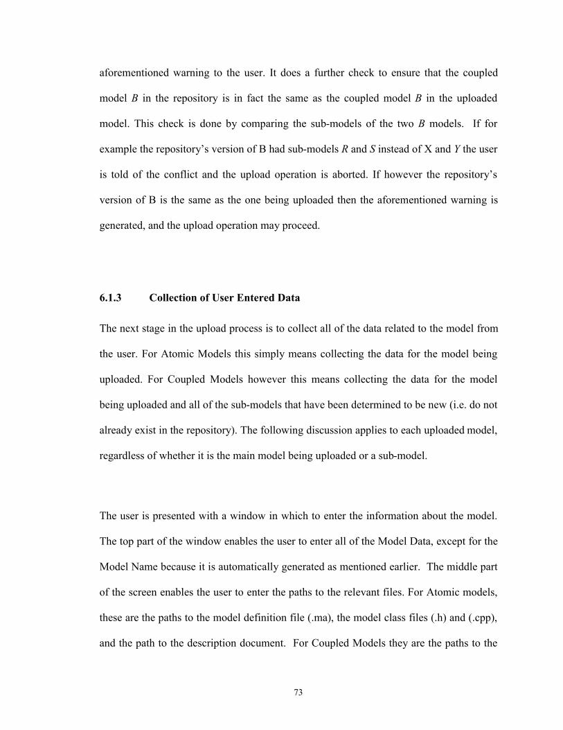
73
aforementioned warning to the user. It does a further check to ensure that the coupled
model B in the repository is in fact the same as the coupled model B in the uploaded
model. This check is done by comparing the sub-models of the two B models. If for
example the repository’s version of B had sub-models R and S instead of X and Y the user
is told of the conflict and the upload operation is aborted. If however the repository’s
version of B is the same as the one being uploaded then the aforementioned warning is
generated, and the upload operation may proceed.
6.1.3 Collection of User Entered Data
The next stage in the upload process is to collect all of the data related to the model from
the user. For Atomic Models this simply means collecting the data for the model being
uploaded. For Coupled Models however this means collecting the data for the model
being uploaded and all of the sub-models that have been determined to be new (i.e. do not
already exist in the repository). The following discussion applies to each uploaded model,
regardless of whether it is the main model being uploaded or a sub-model.
The user is presented with a window in which to enter the information about the model.
The top part of the window enables the user to enter all of the Model Data, except for the
Model Name because it is automatically generated as mentioned earlier. The middle part
of the screen enables the user to enter the paths to the relevant files. For Atomic models,
these are the paths to the model definition file (.ma), the model class files (.h) and (.cpp),
and the path to the description document. For Coupled Models they are the paths to the

74
model definition file (.ma) and the description document. Finally, the bottom part of the
screen enables the user to enter the Experimental Frame Data and any Experiments
related to the model. The following section explains the process of uploading an
Experiment and the related Experimental Results. A screen shot of the top part of this
window is shown in Figure 14; the bottom part of the window is show in Figure 15.
Figure 14: Atomic Model Upload Window Screenshot – Part1
75
Figure 15: Atomic Model Upload Window Screenshot – Part2
6.2 Uploading Experimental Frames, Experiments and Experimental Results
Experiments are entities of their own that exist independently in the CD++ Repository
and that may be linked to one or more models by adding them to the model’s
experimental frame. This means that a user can design the Model and its Experiments
either at the same time or separately, and can upload them to the Repository also either in
the same session or in separate sessions. Therefore, the CD++ Repository allows the user
to enter a new Experiment into the Repository in the following two ways. The first way is
for the user to select to upload an Experiment from the main menu. In this case the
experiment is added to the repository but is not linked to any model. Linking this
experiment to a model can be done later during upload of the model, or by editing an
76
exiting model. The second way is for the user to add a new experiment to the repository
during the upload of a new model. In this case, the Experiment will be linked to the
newly uploaded model. It should be mentioned here that when adding an experiment to a
model during upload of the model the user is given the choice of entering a new
Experiment or linking the model to an existing Experiment. If adding an existing
Experiment is chosen then the user is presented with a search window followed by a
search results window from which the Experiment can be chosen. In this case, the
following description about adding an Experiment does not apply.
Whether uploading a new experiment from the main menu or during the upload of a
model, the user is required to specify the type of Experiment that is being uploaded;
namely, an Event based Experiment, or a Model based Experiment. If the user selects an
Event based Experiment, then they are presented with a window in which to enter the
information about the experiment. The top part of the window enables the user to enter all
of the Experiment Data. The bottom part of the window allows the user to enter the path
to the detailed description document and the other experiment files (.ev, .bat, .val, .pal.,
.drw). This is shown in the screen shot in Figure 16 below. If a user selects a Model
based Experiment on the other hand, they are presented with a similar window containing
the same top part of to enter the Experiment Data. The bottom part of the window
however gives the user the ability to enter the path to a description document for the
experiment, and to add a model that will act as the input “generator” for the experiment
and another model that will act as the output “analyzer” for the experiment. This is shown
in Figure 17 below. The “generator” and “analyzer” models can be selected from models

77
already existing in the repository or can be added as new models. If selected from exiting
models in the Repository the search page is presented followed by the search results page
from which the user can select the model of their choice. The next Section talks more
about searching the repository and the search results page.
Figure 16: Event Based Experiment Upload Window Screenshot

78
Figure 17: Model Based Experiment Upload Window Screenshot
The last item that needs to be uploaded is the experimental results for a given model-
experiment pair. The user is given the opportunity to enter the Experimental Results Data
at the following two places in the application. The first is during the uploading of a new
model to the Repository and right after an Experiment is added to the model, the user is

79
given the opportunity to add Experimental Results data for the model-experiment pair.
The second place is when an existing model is chosen for editing, the user can add the
Experimental Results Information for any experiment within the model’s Experimental
Frame. A screenshot of the window used for adding the Experimental Results
information is shown in Figure 18 below.
Figure 18: Experimental Results Upload Window Screenshot
6.3 Searching and Downloading Models and their Experiments
In the past few sections the discussion concentrated on the ability to upload Models,
Experimental Frames, Experiments and Experimental Results to the CD++ Repository’s
database. This section and the next discuss the ability to search for Models and
Experiments in the CD++ Repository’s database and download them to a CD++ builder
project. Again it is important to note that as far as the CD++ Repository is concerned
Models and Experiments are separate entities that may or may not be linked to each
80
other; therefore the CD++ Repository allows the search and download of each of these
entities independently of the other. When downloading a model however, the CD++
Repository does allow the option to download any attached experiments.
6.3.1 Searching for and Downloading Models
A user can select to download a model from the main menu of the CD++ Repository.
When such a selection is made, the user is presented with a search dialogue window.
This window allows the user to search for a model based on most of the Model Data
described earlier in this chapter. A screenshot of this window is shown in Figure 19
below. This is a simple search window that has the following search features:
The search criteria entered by the user does not have to be full words or
sentences, for example a user can enter “engine” in the title criteria and the
search engine will find all models with the word “engine” in the title.
If one of the search fields is left empty it will not be taken into account during
the search.
If a ‘*’ is entered in one of the fields it means as long as there is a value for
this field (Title, Name , Description … etc) a match will be found. Therefore
to list all models in the Repository a ‘*’ in the name field can be used; this is
because all models must have a Name.
The user is given a choice between using an AND operation or an OR
operation between the search fields. For example, assume a user enters
‘engine’ in the title field and ‘aircraft’ in the Domain field. If the user selects

81
the AND operator, then only models who have ‘engine’ in their title and who
belong to the ‘aircraft’ Domain will be returned. Otherwise, if the OR operator
is selected then all models with ‘engine’ in their title plus all models in the
‘aircraft’ domain will be returned.
Figure 19: Model Search Window Screenshot
For more advanced search features, the user can press the “Advanced Search” button.
This is intended to present a window in which more advanced search features are
presented to the user. Although in the current implementation this feature is not yet
implemented, an example of an important advanced search feature that can be added to

82
this window is the ability to search for models using the Experimental Frame Data fields.
After performing the search, the search results are presented to the user in the Search
Results Window. Figure 20 shows a screenshot of the Search Results Window. As shown
in the screenshot, the window is divided into three main areas: the top (referred to in the
rest of this section as the Selection Pane), the bottom left (referred to in the rest of this
section as the Search Results Pane), and the bottom right (referred to in the rest of this
section as the Details Pane). The rest of the section describes each of these areas in more
detail.
Figure 20: Search Results Window Screenshot
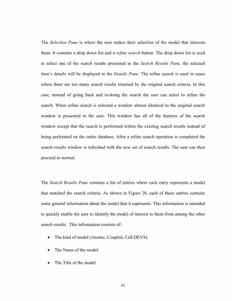
83
The Selection Pane is where the user makes their selection of the model that interests
them. It contains a drop down list and a refine search button. The drop down list is used
to select one of the search results presented in the Search Results Pane, the selected
item’s details will be displayed in the Details Pane. The refine search is used in cases
where there are too many search results returned by the original search criteria. In this
case, instead of going back and re-doing the search the user can select to refine the
search. When refine search is selected a window almost identical to the original search
window is presented to the user. This window has all of the features of the search
window except that the search is performed within the existing search results instead of
being performed on the entire database. After a refine search operation is completed the
search results window is refreshed with the new set of search results. The user can then
proceed as normal.
The Search Results Pane contains a list of entries where each entry represents a model
that matched the search criteria. As shown in Figure 20, each of these entries contains
some general information about the model that it represents. This information is intended
to quickly enable the user to identify the model of interest to them from among the other
search results. This information consists of:
The kind of model (Atomic, Coupled, Cell-DEVS).
The Name of the model.
The Title of the model.

84
The Domain of the model.
The first few words of the Brief Description paragraph.
Finally, the Details Pane displays all of the information concerning the search result item
selected by the user. At the top of the pane is an area in which all of the Model Data and
Experimental Frame Data for the selected model is displayed, including a listing all of the
experiments for the selected model and the experimental results for each experiment. In
Figure 20 above, we can see some of the information for the model named SimCard (the
user would scroll down to see the rest of this information). The View Details button
enables the user to view the detailed description document for the selected model. A click
of this button opens this document in an MS Word window (this requires having MS
Word installed on the client PC). In fact, the user can open the description document of
more than one of the search results at the same time. Finally, and perhaps most useful of
all, a drop down list and a text box enable the user to view the text contained in any of the
selected model’s files. The user can select to display the text contained in the (.ma) (.cpp)
or (.h) files by selecting the appropriate file type from the drop down list. In Figure 20,
we can see the top of the (.ma) file for the selected model.
After looking through the search results, the user would eventually find a model that they
are interested in downloading. At this point, they can proceed to the download window
by pressing the download button. The download window, shown in Figure 21, allows the
user to download any or all of the following items:

85
The selected Model’s files ((.ma) (.cpp) (.h)) and the description document.
The child models of a Coupled model can optionally be also downloaded.
Any or all of the Experiments linked to the selected model. By downloading an
experiment, the files related to the experiment are downloaded. These include the
experiment description document and for Event Based Experiments the (.ev),
(.bat), (.drw), (.pal), and (.val) files, while for Model based Experiments the
model files of the ‘generator’ and ‘transducer’ models.
Figure 21: Download Window Screenshot

86
Once the download operation is started, if the user selected to download the model into a
new project they will first be presented with the CD++ new project dialogue window.
After creating the new project the user is presented with the unzip wizard for each item
that they chose to download. The zip wizard gives the user an opportunity to select the
exact files that they want to download to their project, and gives them a chance to select a
different project to download into. The zip wizard is used because, as was mentioned in
previous chapters, all of the files related to an experiment or model are actually stored as
(.zip) files on the FTP server portion of the repository’s database. Once the download is
complete, the use is ready to use CD++ Builder to run or build upon the downloaded
models and/or experiments.
6.3.2 Searching for and Downloading Experiments
The user can select to download an Experiment from the main menu of the CD++
Repository. The search dialogue window presented to the user allows the user to search
for an Experiment in two ways, either using the Experiment Data to directly search for
experiments in the database, or using the Model data to search for models and then create
search results composed of the Experiments that are linked to the models found in the
search. A screenshot of this window is shown in Figure 22 below. Note that the same
search features described for the model search window apply to this search window as
well. Also similar to the model search window, the user can select the Advanced Search
button for a more advanced search.

87
Figure 22: Experiment Search Window Screenshot
After performing the search, the search results are presented to the user in the Search
Results Window. This window is identical to the one described in the previous section
(and shown in Figure 20) for model search results except that it except that it contains

88
experiments and experiment related information. Therefore, the Search Results Pane now
contains entries representing experiments that matched the search criteria. Also, the
general information presented in this pane is now composed of the following information:
The Name of the experiment.
The Title of the experiment.
The kind of experiment it is (event-based or model-based).
The first few words of the Brief Description paragraph.
Similarly, the Details Pane now contains the selected experiment’s information. The area
at the top of the pane now contains the Experiment Data along with the information for
all of the EFs that reference the selected experiment. The rest of the Details Pane is the
same as that for the model search results, except of course that the drop down list and text
box now enable the viewing of the experiment files instead of the model files. When the
user has found the experiment that they want to download and they press the download
button, the download window, shown in Figure 23, is displayed. The window gives the
user the option to download the selected experiment either into a new CD++ project or
into an existing CD++ project. For event-based experiments, the downloaded files
include the experiment description document, (.ev), (.bat), (.drw), (.pal), (.val) and any
other files linked to the experiment, while for model-based experiments the downloaded
files include the experiment description document and the model files of the ‘generator’
and ‘transducer’ models. The rest of the download operation proceeds as described in the
previous section for the model download window. Once the download is complete, the

89
user is ready to use CD++ Builder to run or build upon the downloaded experiments.
Figure 23: Experiment Download Window Screenshot
6.4 Editing Models and Experiments
A user can choose to modify a model or experiment that already exists in the database.
The user is allowed to modify certain parts of a stored model or experiment, but there are
some items that cannot be modified by the user because modifying them would amount to
corrupting the database for other users. More specifically, the descriptive information
related to a model or experiment can be modified with no adverse affects; and similarly
the set of experiments related to a model can be modified (either by adding an experiment
to a model’s experimental frame or by removing an experiment from a model’s
experimental frame) also with no adverse affects. However modifying the actual CD++
files that define the model or experiment would have a negative affect on the correctness
of the database. For example suppose a model of a traffic light exists in the database and

90
a user uses this model as a component in a model of an intersection and then the user
uploads the intersection model to the database. At this point suppose that the traffic
light’s model definition files were modified (for example by changing it to be activated
by sensors rather than on a timed basis). Now if anyone tries to download the model of
the intersection they will get as part of it the new traffic light model, but the model of the
intersection was designed and tested for the old model and thus more than likely the
model of the intersection will now be broken.
One might ask how a user could then improve the design of an existing model. The
answer for the current implementation of the CD++ Repository is to download the model
that needs improvement, modify it, and then upload the modified model as a new model
with a new name. Future implementations of the CD++ Repository could allow
modifying a model or experiment by attaching a version to each stored model and
experiment. By doing so the CD++ Repository would maintain the old version of a model
and add a new modified version. This way any coupled models that include the modified
model in their hierarchy would maintain their links to the old version of the model and
thus the correctness of the database would be maintained. Some prototyping work has
been done with this versioning scheme and it was found that it is not too difficult to
implement.
As far as the editing feature of the current implementation of CD++ Repository is
concerned the user is first presented with the same search window described earlier to
search for the model or experiment they intend to modify. The user is then presented with

91
the search results window from which they can select the model or experiment that they
want to modify. The user is then allowed to change any of the Model / Experiment /
Experimental Frame Data. In addition the user is allowed to change the set of
experiments that relate to a model and the experimental results for those experiments.
After the required changes are made the user finalizes the transaction so that the
modifications can be saved in the database. If the user takes too long to make a
modification before finalizing their transaction and in that time the model or experiment
that they are modifying was modified by another user then they will be prompted with an
error message explaining what happened and are asked to redo their transaction.
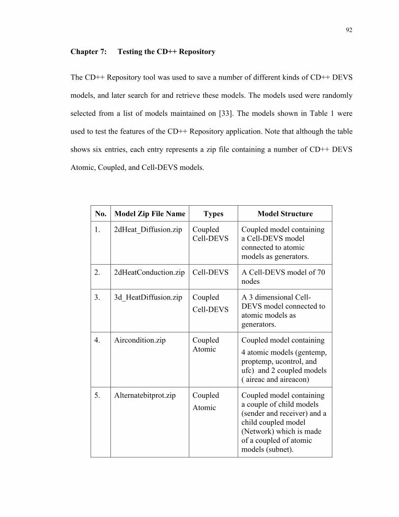
92
Chapter 7: Testing the CD++ Repository
The CD++ Repository tool was used to save a number of different kinds of CD++ DEVS
models, and later search for and retrieve these models. The models used were randomly
selected from a list of models maintained on [33]. The models shown in Table 1 were
used to test the features of the CD++ Repository application. Note that although the table
shows six entries, each entry represents a zip file containing a number of CD++ DEVS
Atomic, Coupled, and Cell-DEVS models.
No. Model Zip File Name Types Model Structure
1. 2dHeat_Diffusion.zip Coupled
Cell-DEVS
Coupled model containing
a Cell-DEVS model
connected to atomic
models as generators.
2. 2dHeatConduction.zip Cell-DEVS A Cell-DEVS model of 70
nodes
3. 3d_HeatDiffusion.zip Coupled
Cell-DEVS
A 3 dimensional Cell-
DEVS model connected to
atomic models as
generators.
4. Aircondition.zip Coupled
Atomic
Coupled model containing
4 atomic models (gentemp,
proptemp, ucontrol, and
ufc) and 2 coupled models
( aireac and aireacon)
5. Alternatebitprot.zip Coupled
Atomic
Coupled model containing
a couple of child models
(sender and receiver) and a
child coupled model
(Network) which is made
of a coupled of atomic
models (subnet).

93
6. Atm.zip Coupled
Atomic
Coupled model containing
2 Atomic models
(cashDispenser and
CardReader) and a coupled
model (authorization)
which is composed of 3
atomic models
(BalanceVerifier,
PINverifier, and
UserInterface)
Table 1: Table of Model Zip Files Used During Testing
For this test, the CD++ Repository Client application was installed on a PC located
outside campus and connected to the internet using a high-speed DSL modem. The SQL
and FTP servers for the CD++ Repository were installed on a machine in the VSIM
Building’s graduate lab at Carleton University. The selected model’s zip files were first
downloaded from [33] to the PC where they were unzipped. Then the following aspects
and features of the CD++ Repository were tested using these models. Note that Table 2
contains tests of the features related to the models, while Table 3 contains the tests of the
features related to the Experiments.
Feature to Test Model Zip File Used Result
Uploading of a single atomic DEVS model. Aircondition.zip
Alternatebitprot.zip
Passed
Uploading of a Cell-DEVS model. 2dHeatConduction.zip
2dHeat_Diffusion.zip
3d_HeatDiffusion.zip
Passed
Uploading of a coupled DEVS model and
its children.
2dHeat_Diffusion.zip
Aircondition.zip
Passed

94
Alternatebitprot.zip
Atm.zip
Uploading of a DEVS model and its
experiment(s) in one operation. Also
uploading experimental results for each
experiment.
3d_HeatDiffusion.zip
Aircondition.zip
Alternatebitprot.zip
Atm.zip
Passed
Attempting to upload an atomic DEVS
model that already exists in the database.
Aircondition.zip
Alternatebitprot.zip
Passed
Attempting to upload a coupled DEVS
model that already exists in the database.
Aircondition.zip
Alternatebitprot.zip
Passed
Attempting to upload coupled DEVS
models containing child coupled models
that conflict with the repository stored
models.
Alternatebitprot.zip Passed
Attempting to upload coupled DEVS
models containing child models that exist
in the database.
3d_HeatDiffusion.zip
Aircondition.zip
Atm.zip
Passed
Using the search capability to find models
by different criteria, and using OR and
AND operator between criteria.
Aircondition.zip
3d_HeatDiffusion.zip
2dHeat_Diffusion.zip
Atm.zip
Passed
Using the refine search feature on the
model search results page.
3d_HeatDiffusion.zip
2dHeatConduction.zip
2dHeat_Diffusion.zip
Passed
Verify that on the model search results
page all information of the selected model
is displayed correctly.
3d_HeatDiffusion.zip
2dHeatConduction.zip
Alternatebitprot.zip
Passed
Using the view details button on the model
search results page to display the detailed
description of the model (MSWord
document) in a separate window.
3d_HeatDiffusion.zip
Alternatebitprot.zip
Passed
Using the drop down list and text box on
the model search results page to display the
3d_HeatDiffusion.zip
Aircondition.zip
Passed
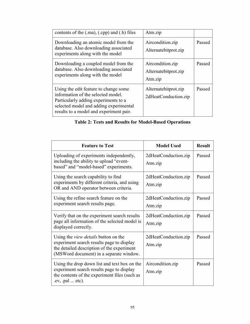
95
contents of the (.ma), (.cpp) and (.h) files Atm.zip
Downloading an atomic model from the
database. Also downloading associated
experiments along with the model
Aircondition.zip
Alternatebitprot.zip
Passed
Downloading a coupled model from the
database. Also downloading associated
experiments along with the model
Aircondition.zip
Alternatebitprot.zip
Atm.zip
Passed
Using the edit feature to change some
information of the selected model.
Particularly adding experiments to a
selected model and adding experimental
results to a model and experiment pair.
Alternatebitprot.zip
2dHeatConduction.zip
Passed
Table 2: Tests and Results for Model-Based Operations
Feature to Test Model Used Result
Uploading of experiments independently,
including the ability to upload “event-
based” and “model-based” experiments.
2dHeatConduction.zip
Atm.zip
Passed
Using the search capability to find
experiments by different criteria, and using
OR and AND operator between criteria.
2dHeatConduction.zip
Atm.zip
Passed
Using the refine search feature on the
experiment search results page.
2dHeatConduction.zip
Atm.zip
Passed
Verify that on the experiment search results
page all information of the selected model is
displayed correctly.
2dHeatConduction.zip
Atm.zip
Passed
Using the view details button on the
experiment search results page to display
the detailed description of the experiment
(MSWord document) in a separate window.
2dHeatConduction.zip
Atm.zip
Passed
Using the drop down list and text box on the
experiment search results page to display
the contents of the experiment files (such as
.ev, .pal ... etc).
Aircondition.zip
Atm.zip
Passed
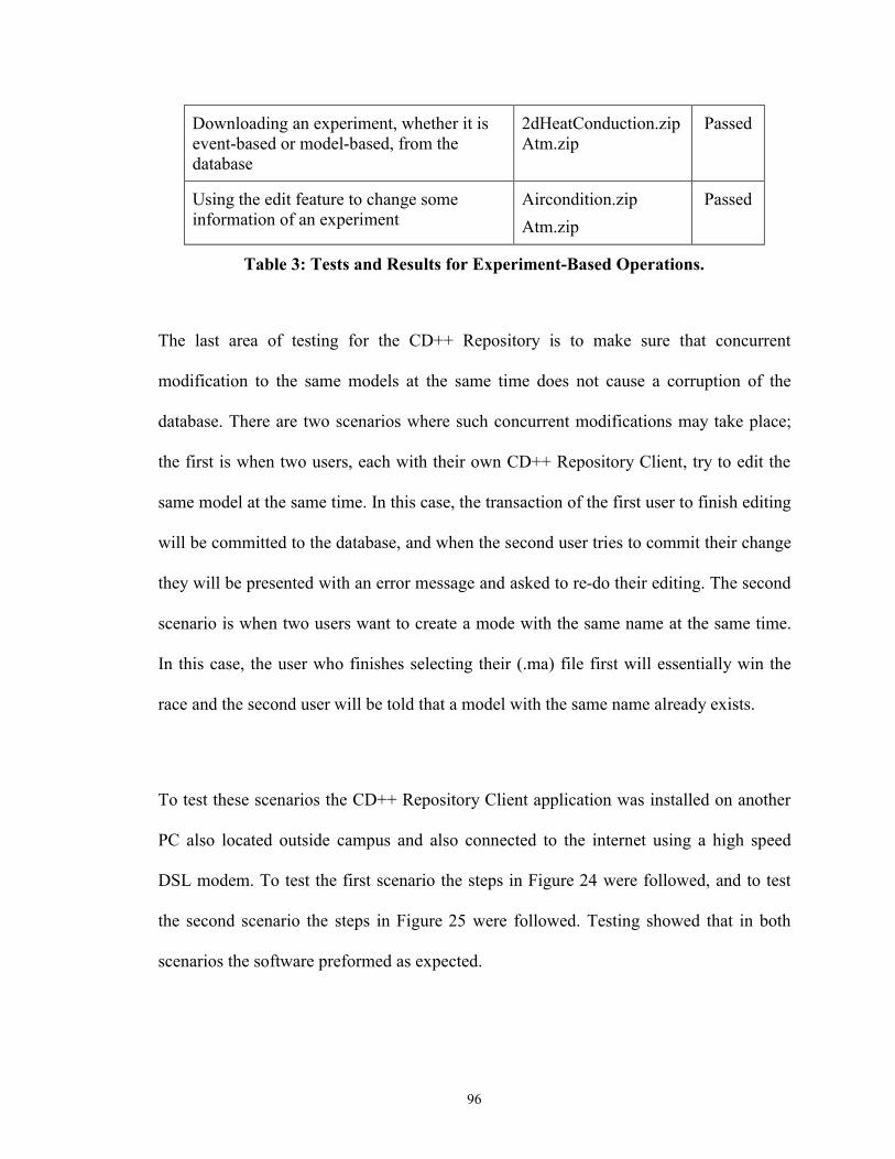
96
Downloading an experiment, whether it is
event-based or model-based, from the
database
2dHeatConduction.zip
Atm.zip
Passed
Using the edit feature to change some
information of an experiment
Aircondition.zip
Atm.zip
Passed
Table 3: Tests and Results for Experiment-Based Operations.
The last area of testing for the CD++ Repository is to make sure that concurrent
modification to the same models at the same time does not cause a corruption of the
database. There are two scenarios where such concurrent modifications may take place;
the first is when two users, each with their own CD++ Repository Client, try to edit the
same model at the same time. In this case, the transaction of the first user to finish editing
will be committed to the database, and when the second user tries to commit their change
they will be presented with an error message and asked to re-do their editing. The second
scenario is when two users want to create a mode with the same name at the same time.
In this case, the user who finishes selecting their (.ma) file first will essentially win the
race and the second user will be told that a model with the same name already exists.
To test these scenarios the CD++ Repository Client application was installed on another
PC also located outside campus and also connected to the internet using a high speed
DSL modem. To test the first scenario the steps in Figure 24 were followed, and to test
the second scenario the steps in Figure 25 were followed. Testing showed that in both
scenarios the software preformed as expected.

97
Concurrent editing of repository elements:
o On PC #1 start editing a model with name “foo”.
o On PC#2 start editing the same model “foo”.
o Complete editing of “foo” from PC#1.
o Attempt to complete editing from PC#2.
An error message is given asking user to redo editing.
Figure 24: Concurrent editing of Models Test
Concurrent upload of repository elements with same name:
o On PC#1 start uploading a model with name “foo”.
o On PC#2 start uploading a model with name “foo”.
o On PC#1 finish selecting the (.ma) file for the model.
o On PC#2 try to upload the same model “foo”.
An error message is given saying “foo” already exists.
Figure 25: Concurrent Upload of Models with Same Name Test
98
Chapter 8: Conclusion and Future Work
DEVS modelling and simulation environments would benefit greatly if they were
associated with a repository of DEVS models and experiments. Users of these simulation
environments could then share and reuse models and experiments. In addition, the
availability of this repository from any geographical locations allows teams of modellers
that are far away from each other to collaborate in their work.
In this thesis, we presented an architecture for an Internet-based repository of DEVS
models and experiments. It was shown that earlier work related to the creation of model
repositories was not suited for adequate model reuse. The architecture presented here had
several contributions. The first is the idea of storing, along with the models, the EF for
these models. The EF holds the context of use information for the model and contains the
experiments applicable to the model. This allows users of the repository to reuse models
and experiments. In addition, the repository stores the experimental results thus allowing
users to reproduce results and thus verify the fidelity of the models. The second is in
specifying the exact storage entities that need to be created, the relationships between
these entities and the information that each entity should include. Thirdly, the proposed
architecture enables the creation of “open source” repositories where users from all over
the world could connect to, upload, and download items to/from the repository. Finally,
by being general enough in its design, the architecture is a small step towards allowing
collaboration among users of different DEVS tools.
A prototype application based on the proposed architecture was implemented for the

99
CD++ Builder Toolkit. This application, CD++ Repository, was presented in this thesis
and tested to show how the proposed architecture could work in a real application. Using
the CD++ Repository one can easily follow the theoretical modeling process presented in
[12] to build complex models.
8.1 Future Work
The proposed repository architecture provides a step in the direction of enabling DEVS
modellers to reuse models in their endeavour to build models that are more complex and
thus enabling teamwork in this area. Future work in this area however can improve on the
current abilities and features of this application. Some of the areas on which work can be
done include:
1. The current repository architecture uses relational database tables to store all of
the information in the library. An important research area would be to replace the
existing relational database with a database based on the OWL ontology language.
This means major changes to the repository servers. It will require building OWL
ontology for the DEVS models and their Experimental Frames. Achieving this
will allow users to use semantics in their queries of the database and will provide
a more powerful search capability. The area of OWL and the semantic web is a
new and expanding area of research.
2. The current architecture of the repository is intended to be used for a single DEVS
simulation tool. This is because the model files stored in the repository are
specific to a given tool. Research is required to somehow store a general format of

100
the DEVS model in the repository and thus allow any DEVS simulation tool to
download all of the stored models. This would allow true interoperability between
the different DEVS simulation tools.

101
References
[1] Ted Biggerstaff and Alan Perlis (Eds). 1989. Software Reusability, volume 1 & 2.
ACM Press, NY.
[2] Zeigler, B.; H. Praehofer; T.G. Kim. 2000. Theory of Modeling and Simulation, 2nd
Edition. Academic Press, San Diego, CA.
[3] Traore M.K., and A. Muzy. 2006. “Capturing the Dual Relationship Between
Simulation Models and Their Context.” Simulation Modeling Practice and Theory,
Vol. 14, No.2, (February): 126-142
[4] Chidisiuc K. and G. Wainer. 2008. “CD++Modeler: A Graphical Toolkit to Develop
DEVS Models.” Poster Paper. In Proc. of SpringSim’08. Ottawa, ON. 2008.
[5] Chreyh R. and G. Wainer. 2009. “CD++ Repository: An Internet Based Searchable
Database of DEVS Models and Their Experimental Frames.” In Proceedings of
SpringSim’09, March 23-25, in San Diego, CA, USA.
[6] Macleod M.; R. Chreyh; G. Wainer. 2006. “Improved cell-DEVS Models for Fire
Spreading Analysis.” In Proceedings of the 7th International Conference on Cellular
Automata for Research and Industry, ACRI 2006, September 20-23, in Perpignan,
France. Vol. 4173, pp. 472-481.
[7] Bernardi F., J.-B. Fillipi, and J.-F. Santucci. 2003. “A Generic Framework For
Environmental Modeling and Simulation.” In Proceedings of the 2003 IEEE
International Conference on Systems, Man and Cybernetics, October 5-8, in
Washington, DC. 1810-1815 Vol. 2.
102
[8] Wainer G.; N. Giambiasi. 2001. “Timed Cell-DEVS: Modeling and Simulation of
Cell Spaces.” Invited paper for the book Discrete Event Modeling & Simulation:
Enabling Future Technologies. Springer-Verlag.
[9] Zeigler, B. 1984. Multifaceted Modeling and Discrete Event Simulation. Academic
Press, London.
[10] Barros F. J.; A. Lehmann; P. Liggesmeyer; A. Ver-braeck; B. P. Zeigler. 2006.
“04041 Abstracts Collection -- Component-Based Modeling and Simulation.” In
Proceedings of Dagstuhl Seminar 04041 Component-Based Modeling and
Simulation, Jan. 1, in Dagstuhl, Germany.
[11] Bernardi, F.; J.F. Santucci. 2002. “Developing a Web-Based Models Library for a
DEVS Modeling and Simulation Environment.” In Proceedings of AIS 2002, April 7
-10, in Lisbon, Portugal.
[12] Bernardi, F.; J.F. Santucci. 2002. “Model Design Using Hierarchical Web-Based
Libraries.” In Proceedings of the 39th
Conference on Design Automation, June 9-14,
New Orleans, USA. Vol. 1, pp. 14-17.
[13] Bernardi, F.; E. de Gentili; and J. Santucci. 2001. “Reusable Models Integration in a
DEVS-Based Modelling and Simulation Environment.” In Proceedings of ESS2001,
Oct. 18-20, Marseille, France.
[14] Mocko, G.; Malak Jr., R. J.; Paredis, C. J. J.; and Peak, R. 2004. "A Knowledge
Repository for Behavioral Models in Engineering Design." In Proceedings of the 24th
ASME Computers and Information in Engineering Conference, Sept. 28-Oct. 2, Salt
Lake City, UT, ASME DETC2004-57746.

103
[15] Breunese, A. P. J.; Top, J. L.; Broenink, J. F.; and Akkermans, J. M. 1998. “Libraries
of Reusable Models: Theory and Application.” Simulation. Vol. 71, (July): pp. 7 - 22.
[16] Garrido, J. M.; and Amit, J. 2005. "A Repository for Multi-Disciplinary
Computational Models and Tools." In Proceedings of the 43rd annual Southeast
Regional Conference, March 18-20, Kennesaw, Georgia. Vol. 1 : pp. 315-316.
[17] Balci, O. 1998. “A Library of reusable Model Components for Visual Simulation of
the NCSTRL System.” In Proceedings of the 1998 Winter Simulation Conference,
Dec. 13-16, Washington DC. 1451-1460.
[18] Son, Y. J.; Jones, A.T.; Wysk, R.A. 2000. “Automatic Generation of Simulation
Models from Neutral Libraries: An Example.” In Proceedings of the 2000 Winter
Simulation Conference, Dec.10-13, Wyndham Palace Resort & Spa, Orlando, FL.
1558-1567.
[19] Praehofer, H.; Sametinger, J.; and Stritzinger, A. 2000. “Building Reusable
Simulation Components.” In Proceedings of WEBSIM2000, Web-Based Modelling
& Simulation, Jan 23-27, San Diego, CA, USA. Vol. 1. pp. 1-7.
[20] NS-2 website. Available at: http://nsnam.isi.edu/nsnam/index.php/User_Information.
[Accessed March, 2009]
[21] OMNeT++ website. Available at: http http://www.omnetpp.org. [Accessed March,
2009]
[22] OPNET Technologies Inc. website. Available at: http://www.opnet.com. [Accessed
March, 2009]

104
[23] Wainer, G. DEVS Tools website. Available at: http://www.sce.carleton.ca/faculty/
wainer/standard/tools.htm. [Accessed March, 2009]
[24] Nutaro, J. ADEVS website. Available at: http://www.ornl.gov/~1qn/adevs. [Accessed
January, 2009]
[25] Zeigler, B.; Y. Moon; D. Kim; J. G. Kim. 1996. “DEVS-C++: A high performance
modeling and simulation environment.” In The 29th
Hawaii International Conference
on System Sciences, Jan. 3-6, Maui, Hawaii.
[26] Zeigler, B.; H. S. Sarjoughian. 1999. “Support for hierarchical modular component-
based model construction in DEVS/HLA.” Simulation Interoperability Workshop,
March 14-19, Orlando, FL.
[27] Sarjoughian, H. S. and B. Zeigler.1998. “DEVSJAVA: Basis for a DEVS-based
collaborative M&S environment.” In Proceedings of The International Conference on
Web-Based Modeling and Simulation, Jan. 11-14, San Diego, CA. USA. Vol. 5, pp.
29-36.
[28] Filippi, J. B.; F. Bernardi; M. Delhom. 2002. “The JDEVS Modeling and Simulation
Environment’. In Proceedings of the Integrated Assessment and Decision Support
Conference (IEMSS’02), Jun. 24-27, Lugano, Switzerland. 283-288.
[29] Praehofer, H.; J. Sametinger; A. Stritzinger. 1999. “Discrete Event Simulation Using
the JavaBeans Component Model.” In Proceedings of the International Conference on
Web-Based Modeling & Simulation, Jan. 17-20, San Francisco, CA. USA.
[30] Bauer C.; G. King. 2005. Hibernate In Action. Manning Publications Co., Greenwich,
CT.

105
[31] Weathersby J.; D. French; T. Bondur; J. Tatchell; I. Chatalbasheva. 2006. Integrating
and Extending BIRT. Addison-Wesley, New York.
[32] Wainer, G; L. Morihama; V. Pasuello. 2002. “Automatic Verification of DEVS
Models.” In Proceedings of 2002 Spring Simulation Interoperability Workshop,
March 10-15, Orlando FL,
[33] Wainer, G. DEVS Tools website. Available at: http://www.sce.carleton.ca/faculty/
wainer/wbgraf/samplesmain_1 [Accessed March, 2009]
106
Appendix-A: CD++ Repository Software Details
1. Persistence Layer Java Packages
In the previous section Hibernate was introduced as a layer that sits at the interface with
the database and handles the mapping of the Business Objects to the database tables. As
such Hibernate is a major part of the persistence layer of the CD++ Repository. The use
of Hibernate does make things easier in terms of solving the object-relational mismatch
problem, but one must have a good understanding of Hibernate in order to use it correctly
in a Java application. One main requirement for the use of Hibernate is that the objects
being persisted must be attached to a Hibernate session for Hibernate to be able to save
them to the database. Objects that are attached to a session are called persistent objects,
while those not attached to a session are called either detached objects if they were
attached to a session that is now closed, or transient objects if they have not been attached
to a session yet. Another thing to note about Hibernate is the session and transaction
demarcation issues; that is when to open a session and when to close it, and when to start
a transaction and when to commit it. For example, one should not have a Hibernate
session or transaction open during user interaction. Other concepts one needs to
understand when using Hibernate include transitive persistence strategies, concurrency
and automatic versioning, and even caching options for optimizing performance. The
CD++ Repository’s architecture tries to hide most of the details that deal with the use of
Hibernate inside the Persistence Layer. Therefore a few packages and utilities have been
built to encapsulate the database services required by the Presentation layer such that
Presentation layer code is not bogged down with Hibernate programming details. The
next sub-sections introduce these Persistence layer packages and utilities.

107
1.1. The HibernateUtil Class
This is the utility used to start Hibernate. It contains a static SessionFactory attribute and
a static getter function for it. An initialization method called InitializeSessionFactory()
exists to instantiate and configure the Hibernate SessionFactory by loading configuration
information from the Hibernate configuration file as well as using the CD++ Repository
preferences page to get information required to connect to the appropriate SQL server
and database. The SessionFactory is instantiated only once when the CD++ Repository is
first started and it is used throughout the life of the application. Other utility methods that
are made available to the Presentation Layer by this class are:
attachToSession(): Used to attach a detached object to a session. This is useful in
situations where the object being attached contains a graph of other objects whose
values need to be accessed from the database.
commitSessionTx(): Used to end the transaction and close the session started by
attachToSession().
mergeObject(): This method opens a session, updates (merges) the database with
the passed in detached object’s information, and closes the session.
1.2. The RepositorySearchUtil Class
This utility provides the following methods that allow inspection of the repository with
respect to a given Model or Model name:

108
1. isInConflictWithRepo(): This method determines whether a passed in coupled
model has the same structure (i.e. the same number of atomic and coupled child
models) as the matching coupled model (by name) in the repository.
2. modelNameInRepository(): This method determines if the passed in model name
already exists in the repository.
3. getAtomicModelFromRep() and getCoupledModelFromRep: These two methods
search the repository for a model matching the passed in model name and return
the model object if it is found.
1.3. The dataAccessObjects Package
This package contains a data access class for each business object. This means that there
is an ExperimetDAO class, a ModelDAO class, an ExperimentalFrameDAO and so on.
The data access classes are intended to hide the details of how the database is accessed
and searched to obtain an object from the database. Each class contains a number of
methods intended to facilitate searching for items in the database or adding items to the
database. The following are examples of the types of methods in the DAO classes:
Search by attribute methods. These are intended to search the database based on
a specific attribute of the business object in question. These methods take in a
search string and return a set of objects that matched the search string in the
database. For example the modelDAO class contains, among other methods, the
following:
o findByDescription(): This method searches the database and returns all

109
models whose description attribute contains the passed in string.
o findByTitle(): This method searches the database and returns all models
whose title attribute contains the passed in string.
Search by attribute and set-of-object-names methods. These methods are similar
to the ones described above except that in addition to the search string a set of
object names is passed in. These methods are used to search the database based
on a specific attribute and based on the set of names that are passed in. These
methods are useful when doing refine search operations.
Add methods. These methods are used to add a given object, or map of objects
to the database.
The DAO classes hide the Hibernate Query Language (HQL) being used to do the
searching in the database and hide the implementation of the search and add methods.
This separation of concerns promotes maintainability of the software so that if
improvements are to be implemented to the search algorithm for example it will only
affect the DAO classes. Note that these DAO Classes are not intended to be called
directly by the presentation layer. The next section introduces the databaseServices
package which contains wrappers to the methods in the DAOs and these are the ones that
the Presentation layer accesses.
1.4. The datbaseServices Package
The databaseServices package also contains a class for each business object. Each class
110
provides database services for the related business object. The majority of the methods in
these classes are similar to the methods of the DAO classes. In fact each of the search and
add methods of the DAO classed is encapsulated by a similar method in the
corresponding databaseService class. In addition some of the databaseService classes
contain methods that are used to perform more complicated functions such as more
advanced searches of the database. The more important of these methods are listed
below:
The findModels() method in the ModelService class is used by the Presentation
layer to find the models, both coupled and atomic, that match certain search
criteria that are passed into it. This method takes in a list of criteria such as name,
description, title, and a corresponding list of strings for each criterion. In addition
it takes in an indicator to whether an OR or an AND operation should be used
between these search criteria. This method makes use of the DAO classes and
methods to perform the search in the database, and returns a list of models that
match all of the search criteria using the appropriate operator.
The refineModels() method in the ModelService class is used by the Presentation
layer to do a “refine search” operation on a set of Model search results. This
method takes in a list of criteria such as name, description, title, a corresponding
list of strings for each criterion, and a set of names of the models to do the refine
search on. In addition it takes in an indicator to whether an OR or an AND
operation should be used between the search criteria. This method makes use of
the DAO classes and methods to perform the refine search, and returns a list of
models that match all of the search criteria.

111
The findExperiments() method in the ExperimentService class is used by the
Presentation layer to find the Experiments that match certain search criteria that
are passed into it. This method is very similar to the findModels() method.
The refineExperiments() method in the ExperimentService class is used by the
Presentation layer to do a “refine search” operation on a set of Experiment search
results. This method is very similar to the refineModels() method.
The createExpFrameWithInputsOutputs() method is found in the
ExperimentalFrameService class and is used by the Presentation layer when
storing the Experimental Frame’s input and output port information. This method
creates a new experimental frame object and assigns to it the values for the inputs
and outputs that were entered by the user. It checks the database for existing
input/output elements. If an element of an input or output is found in the database,
then that element is itself used in the current experimental frame object without
having to create a new one, otherwise if it is not found in the database it is added
to the database and then used in the current experimental frame object. This way
no redundancy exists in the database for input/output elements.
2- Presentation Layer Packages
Since the CD++ Repository is a component of the CD++ Builder Toolkit, which in itself
is an Eclipse plug-in, the interface to the CD++ Repository has to be integrated with the
rest of the CD++ Builder Toolkit plug-in and should have a similar look and feel as the
Eclipse environment. To that end the Presentation layer of the CD++ Repository is
mostly built using the Eclipse Standard Widget Toolkit (SWT) package. Also, to

112
complete the integration, the user preferences for the CD++ Repository application are
integrated in the Eclipse preferences menu under the CD++ Builder Preferences section.
Finally, launching the CD++ Repository application is done through a button in the
CD++ Builder toolbar in Eclipse.
Once the CD++ Repository is launched the user is presented with the main CD++
Repository window which allows the user to perform the two main functions of the
CD++ Repository; namely uploading items to the database, and searching for and
downloading items from the database. Therefore there are two main presentation layer
packages, the first contains the classes concerned with uploading and the second contains
classes that are concerned with searching and downloading. The next few sections
explain the structure of these packages in more detail. Note that the CD++ Repository
does also allow the user to edit items in the repository, but this is essentially a
combination of the previous two functions, first an item is downloaded and then edited
and uploaded back to the repository.
2.1- The Gui.Upload Package
This package is the root container of all the user interface classes that deal with the
uploading of items to the database. This package in itself does not contain any classes,
but it contains a number of packages, one for each item that can be uploaded to the CD++
Repository’s database. Figure 26 below shows that under this package there are the
following child packages: model, expFrame, experiment, and experimentalResult; these
are explained in the following sub-sections.
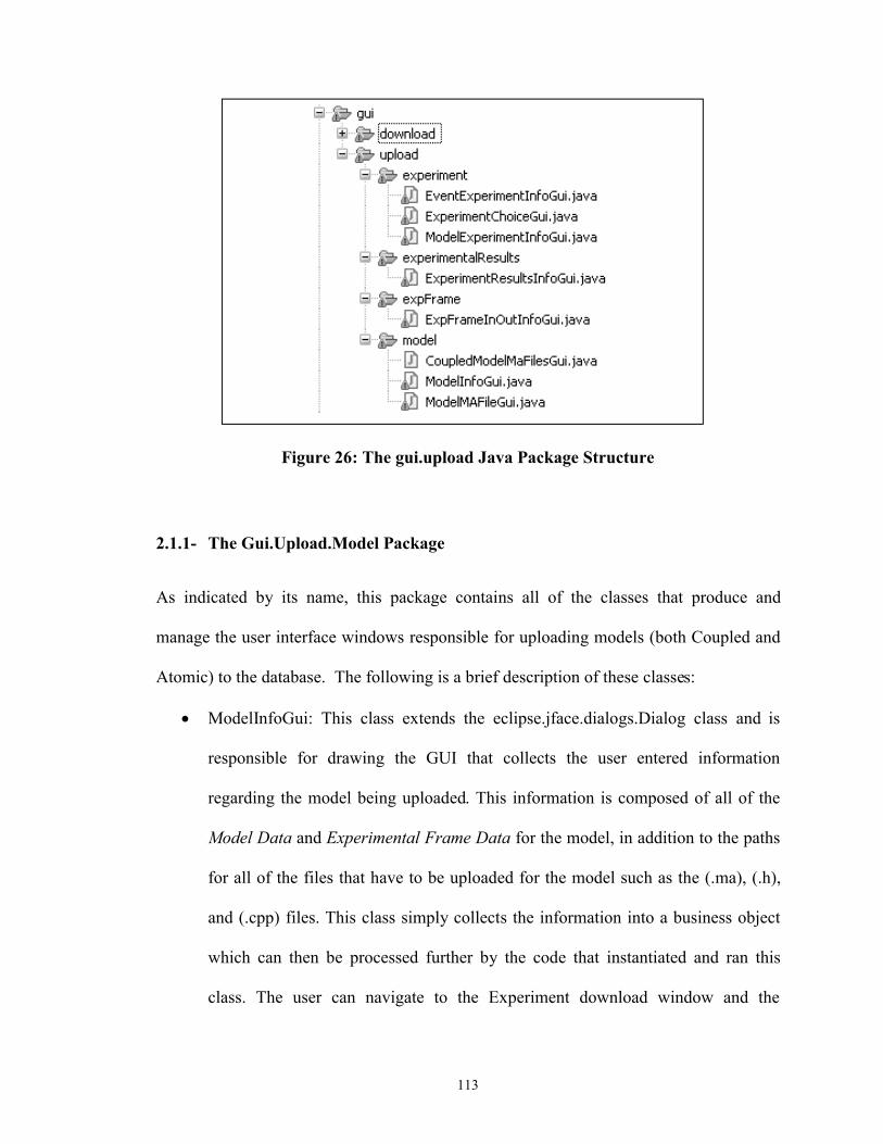
113
Figure 26: The gui.upload Java Package Structure
2.1.1- The Gui.Upload.Model Package
As indicated by its name, this package contains all of the classes that produce and
manage the user interface windows responsible for uploading models (both Coupled and
Atomic) to the database. The following is a brief description of these classes:
ModelInfoGui: This class extends the eclipse.jface.dialogs.Dialog class and is
responsible for drawing the GUI that collects the user entered information
regarding the model being uploaded. This information is composed of all of the
Model Data and Experimental Frame Data for the model, in addition to the paths
for all of the files that have to be uploaded for the model such as the (.ma), (.h),
and (.cpp) files. This class simply collects the information into a business object
which can then be processed further by the code that instantiated and ran this
class. The user can navigate to the Experiment download window and the
114
Experimental Frame additional information upload window from this class as
well.
CoulpedModelMaFileGui: This class is also based on the
eclipse.jface.dialogs.Dialog class and it is responsible for collecting the (.ma) file
paths for the list of model names passed into it. The file paths entered by the user
are stored in a map with corresponding model names, and this map can be
retrieved by the code that instantiated this class.
modelMaFileGui: This class also extends the eclipse.jface.dialogs.Dialog class,
and it is the main entry and control point for all of the model upload process. The
user interface window drawn by this class is simply a text box and a button to
allow the user to enter the path of the (.ma) file for the model that is to be
uploaded. When the user clicks the button, this class calls the appropriate utility
and database service classes to parse the (.ma) file, determine the type of model
being uploaded, determine all the child models (if any), and check for conflicts
with the database as described in earlier chapters, and, in the case of a coupled
model, create a list of the new child models that the user is to enter. If child
coupled models are detected then the CoulpedModelMaFileGui class is
instantiated to collect the paths of the (.ma) files for each of those child coupled
models. Finally the ModelInfoGui class is instantiated to collect the model
information. In the case where a coupled model is being downloaded, then the
ModelInfoGui class is instantiated recursively for all child models that do not
already exist in the database.
115
2.1.2- The Gui.Upload.Experiment Package
This package contains all of the classes that produce and manage the user interface
windows responsible for uploading experiments to the database. The following is a brief
description of these classes:
ExperimentChoiceGui: This class extends the eclipse.jface.dialogs.Dialog class
and is the main entry point for uploading experiments. The window displayed by
this class gives the user an opportunity to choose the type of Experiment they
want to upload; either an event file based experiment, or a model based
experiment. Depending on the choice one of the classes described below is
instantiated to collect the Experiment’s information.
EventExperimentInfoGui: This class extends the eclipse.jface.dialogs.Dialog class
and is responsible for drawing the GUI that collects the user entered information
for event file based experiments. This information is composed of all of the
Experiment Data, in addition to the paths for all of the files related to the
experiment such as the (.ev) and (.doc) files. This class simply collects the
information into a business object which can then be processed further by the
code that instantiated this class. After entering the Experiment’s information the
user is presented with Experimental Results upload window to enter the
experimental result information if any.
ModelExperimentInfoGui: This class extends the eclipse.jface.dialogs.Dialog
class and is responsible for drawing the GUI that collects the user entered
information for model based experiments. This information is composed of all of
the Experiment Data in addition to all of the model information for the model that
116
will act as a generator and the model that will act as a transducer. The model
information is collected either by invoking the ModelInfoGui class to collect
information of a new model, or by invoking the ModelSearchGui class to search
for and select an existing model in the database. This class collects the
information into a business object which can then be processed further by the
code that instantiated this class. After entering the Experiment’s information the
user is presented with Experimental Results upload window to enter the
experimental result information if any.
2.1.3- The Gui.Upload.ExperimentalResults Package
This package contains only one class, the ExperimentalResultsInfoGui, which is
responsible for collecting the experimental results information from the user. This class
collects the required information into a business object which can then be processed
further by the code that instantiated this class.
2.1.4- The Gui.Upload.ExpFrame Package
This package contains only one class, the ExpFrameInOutInfoGui, which is responsible
for collecting the experimental frame’s other information. Note that the regular
Experimental Frame Data is collected by class ModelInfoGui. As mentioned in previous
chapters, this other information is composed of the inputs and outputs of the experimental
frame as described by the formalism in [3]. Collection of this information in the current
version of the CD++ Repository is not required for the rest of the functionality of the tool

117
to operate. This development was done as an example of how the CD++ Repository can
capture information at this level of detail, future development of the CD++ Repository
could make use of this information to more fully describe the interaction of a given
model with other models. This class collects the required information into business
objects which are then added to the Experimental Frame object by the code that
instantiated this class.
2.2- The Gui.Download Package
This package is the root container of all the user interface classes that deal with collecting
the search criteria from the user, displaying the search results to the user, and
downloading the selected item(s) from the database to a CD++ Builder project. This
package in itself does not contain any classes, but it contains a package for models and
another for experiments (the two entities that can be downloaded from the database) and
a couple of other supporting packages. Figure 27 shows the hierarchy under this package
and the following sub-sections give a brief description of the packages in this hierarchy.

118
Figure 27: The gui.download java Package Structure
2.2.1- The Gui.Download.Model Package
This package contains all of the classes that produce and manage the user interface
windows responsible for collecting search criteria, displaying search results and
downloading models (both Coupled and Atomic). The following is a brief description of
these classes:
ModelSearchGui: This class extends the eclipse.jface.dialogs.Dialog class and is
the entry point to the download functionality. It creates the user interface window
responsible for collecting the search criteria and the other search options from the
user. When the user enters the search criteria and presses the search button on this

119
user interface window, the class calls the appropriate search routines from the
Persistence Layer to do the actual search in the database. These search routines
return a list of search results in the form of the business objects of the matching
items. The role of this class ends by instantiating the ModelSerachResults class
and passing it the list of business object search results.
RefineSearchGui: This class extends the eclipse.jface.dialogs.Dialog class and is
almost identical to the ModelSearchGui class. The main difference is that this
class takes in the current set of search results, and invokes the appropriate
database service methods to search for the user entered criteria within the current
search result set. The new search result set is then made available to the code that
instantiated this class.
ModelSearchResultsGui: This class extends the jface.dialogs.Dialog class and is
responsible for generating the user interface window that presents the search
results to the user. This class contain a number of features that help the user select
the model that they desire; the following describes how this class provides these
features:
o In Chapter 6 the presentation of the search results in the Search Results
Pane and in the Details Pane was described in detail. Here we point to the
fact that both of these panes are in fact displaying an html report document
that is generated on the fly by the BIRT tools. This class calls the BIRT
utility class methods to generate the reports for the given set of search
result objects, and then displays the reports in the appropriate pane. More
details about BIRT are presented further on in this appendix.
120
o Chapter 6 also described that the user is able to view the contents of some
of the files of the currently selected item without having to download the
item. When a user selects to view the contents of a file the
FileSystemUtilities, ZipUtil, and CdxxSftputil classes are used to
download the zip file for the selected item (if not already downloaded),
unzip the zip file into a temporary directory (if not already unzipped), and
finally convert its contents into a text string that can be displayed in a
normal text box, and display the text.
o Chapter 6 also described that the MS Word document containing the
detailed description for a given model can be opened for viewing by the
user without having to download the item in question. When the user
selects to view a Word document the FileSystemUtilities, ZipUtil, and
CdxxSftputil classes are used to download and make available the MS
Word document in a temporary directory, and then the classes under
package Gui.Download.MsWordWindow are invoked to display the word
document in a separate window for the user to read.
o Chapter 6 also described the refine search functionality. This functionality
is made available through instantiating the refineSearchGui class
described earlier. After the refine search is performed the contents of the
Search Results Window is updated with the new result set.
o Finally, having chosen a model to download, the user will click the
download button to actually download the selected item. Doing this will
instantiate the ModelDownloadGui class which will handle the display

121
and processing of the user’s download options.
ModelDownloadGui: This class extends the jface.dialogs.Dialog class and is
responsible for generating the user interface window that gives the user a few
options of what exactly they want to download, and where to download the files
to. These options were described in detail in previous chapters. When the user has
made their choices and selected to initiate a download the FileSystemUtilities,
ZipUtil, and CdxxSftputil classes are used to download all the zip files for all the
items (specifically all of the child modes of a coupled model being downloaded)
and package them into one file to be unzipped into the CD++ Project Folder. In
addition, if any Experiments have been selected for download, their zip files are
also downloaded (note that event and model based experiments are handled
separately). Finally the zip wizard classes under the Gui.Download.Wizards
package are used to present the user with a zip wizard that enables them to choose
exactly which files are added to which CD++ Builder project.
2.2.2- The Gui.Download.Experiment Package
This package contains all of the classes that produce and manage the user interface
windows responsible for collecting search criteria, displaying search results and
downloading Experiments. The following is a brief description of these classes:
ExperimentSearchGui: This class is very similar to the ModelSearchGui class
described in the previous section. This class extends the eclipse.jface.dialogs.Dialog
class and is the entry point to the experiment download functionality. It creates the

122
user interface window responsible for collecting the search criteria and the other
search options from the user. Just like the ModelSearchGui class, this class calls the
appropriate search routines from the Persistence Layer to do the actual search in the
database and get the list of search results. The role of this class ends by instantiating
the ExpSearchResultsGui class to present the search results to the user.
The RefineSearchGui class: This class is almost identical to the class with the same
name under the Gui.Download.Model Package bescribed in the previous section.
ExpSerachResultsGui: This class is very similar to the ModelSearchResultsGui class
described in the previous section with the exception that it deals with experiments
instead of models. It provides the same features as the ModelSearchResultsGui.
ExpDownloadGui: This class extends the jface.dialogs.Dialog class and is responsible
for generating the user interface window that gives the user the option of where to
download the experiment files to, a new CD++ Builder project or an existing one.
When the user selects to initiate a download the FileSystemUtilities, ZipUtil, and
CdxxSftpUtil classes are used to download the zip file for the selected experiment.
Finally the zip wizard classes under the Gui.Download.Wizards package are used to
present the user with a zip wizard that enables them to choose exactly which files are
added to the CD++ Builder project.
2.2.3- The Gui.Download.MsWordWindow Package
This package contains a couple of classes that are responsible for opening the MS Word
detailed description documents in a separate window for the user to look at. The

123
following is a brief description of these classes:
MsWordViewerBttnLstnr: This class extends an eclipse selectionAdapter class
and is used as the implementation of the button press event for the “view details”
button found on the search results window. This class makes use of the
FileSystemUtilities, ZipUtil, and CdxxSftpUtil class to ensure that the Ms Word
document is downloaded into the temporary directory, then it instantiates the
WordDocDisplayGui class to open the document in a separate window.
WordDocDisplayGui: This class extends the eclipse ApplicationWindow class. Its
main function is to create an OleFrame object and use it to open the passed-in MS
Word document in a new window.
2.2.4- The Gui.Download.Wizards Package
This package contains a couple of classes that are responsible for presenting the Zip
Wizard to the user when models or experiments are downloaded to a CD++ Builder
project. The two classes under this package are the RepositoryZipWizard class and the
RepositoryZipWizardPage class. Both of these classes are adapted from the standard
eclipse workbench wizard for importing resources from a zip file, and are almost
identical to it presentation wise. Changes were made to the standard wizard to allow
programmatically passing in the name of the file to be unzipped and the default location
(CD++ Builder project) in which to unzip the file.
3- Utility Classes
There are a number of utility classes that are used throughout the CD++ Repository
124
application, and these are all collected in the Repository.Util package. The following is a
list of the more important of these utility classes:
The BirtUtil class: This class contains a number of static methods that are used to
generate the search results page for Experiments and Models. The class makes use
of the BIRT engine (described in the next subsection) and the appropriate BIRT
report design files to generate HTML formatted reports that are displayed in the
search results page.
CdxxSftpClient: This class implements an SFTP (secure FTP) client capable of
uploading and downloading files to the FTP server specified by the IP address in
the configuration.
FileSystemUtilities: This class contains a number of file system related methods
that are used in various places in the application.
HibernateUtil: This class was fully described earlier in section 6.4.1.
MaFileParser: This class is used to parse the model definition (.ma) files for each
model. By parsing the (.ma) file this class is able to build the tree of models under
a coupled model and to determine the input output ports for any model. It has a
number of other methods that query the tree of models built by the parser.
ZipUtil: This class contains methods that are capable of compressing and
uncompressing files using the java.util.zip utility.
4- The Business Intelligence Reporting Tool (BIRT)
125
BIRT is an Eclipse-based open source reporting system that can be used by Java
applications to produce reports from many different kinds of data sources (databases, web
services, Java objects) [31]. BIRT is made of two main components, first the BIRT
Report Designer which is an Eclipse based application that enables users to graphically
build a report and specify where the data that populates the report comes from and also
specify where this data is displayed in the report. The report designer also enables the
user to filter, sort, and do other data transforms in addition to using JavaScript to
structure the raw data into information that can be displayed in the report. The second
component is the BIRT runtime component which will use the report design file created
using the designer to populate a report at runtime.
For the CD++ Repository client application BIRT was used to create four different report
design files; these are files with extension (.rptdesign). The first is used to generate the
report that displays the list of model search results; the second to generate the report that
displays the list of experiment search results; the third is used to generate the report that
displays the details of the selected model from the search results; and finally the fourth is
used to generate the report that displays the details of the selected experiments from the
search results. BIRT is capable of producing reports in many formats including PDF and
HTML. For the Purposes of the CD++ Repository the reports are generated as HTML
documents which are displayed in the appropriate browser objects in the Search Results
window.