canadian payments association association …
TRANSCRIPT

CANADIAN PAYMENTS ASSOCIATION
ASSOCIATION CANADIENNE DES PAIEMENTS
STANDARD 006 SPECIFICATIONS FOR MICR-ENCODED PAYMENT
ITEMS
PART A: SPECIFICATIONS FOR IMAGEABLE MICR-ENCODED PAYMENT ITEMS
(Cheques, Money Orders, Bank Drafts, Inter-Member Debits, Settlement
Vouchers, Canada Savings Bonds, Provincial Savings Bonds, Gift Certificates and Store Coupons, and Paper Pre-authorized Debits)
PART B: SPECIFICATIONS FOR OTHER MICR-ENCODED PAYMENT ITEMS
2017 CANADIAN PAYMENTS ASSOCIATION 2017 ASSOCIATION CANADIENNE DES PAIEMENTS This Standard is copyrighted by the Canadian Payments Association. All rights reserved, including the right of reproduction in whole or in part, without express written permission by the Canadian Payments Association.
By publication of this standard, no position is taken with respect to the intellectual property rights of any person or entity. The CPA does not assume any liability to any person or entity for compliance with this standard, including liability (which is denied) if compliance with the standard infringes or is alleged to infringe the intellectual property rights of any person or entity.
Payments Canada is the operating brand name of the Canadian Payments Association (CPA). For legal purposes we continue to use “Canadian Payments Association” (or the Association) in these rules and in information related to rules, by-laws, and standards.

Standard 006 – Specifications for MICR-Encoded Payment Items
Implemented
February 1992
Amendments Pre-November 2003 November 18, 1992, April 28, 1993, October 15, 1993, February 3, 1994, March 31, 1994, June 1994, March 23, 1995, November 27, 1995, March 25, 1996, May 23, 1996, August 23, 1996, September 18, 1996, November 25, 1996, January 27, 1997, October 9, 1997, May 19, 1998, December 3, 1998, December 7, 1998, July 6, 1999, October 7, 1999, March 8, 2000, May 7, 2000, July 24, 2000, October 5, 2000, May 28, 2001, June 28, 2001, July 26, 2001, November 29, 2001, April 15, 2002, July 15, 2002, November 28, 2002, February 20, 2003, March 31, 2003, June 1, 2003, and January 27, 2004. Amendments Post-November 2003
1. Sections 2.1.3 and 2.7, approved by the Board November 27, 2003, effective January 27, 2004. 2. Standard 006 divided into Part A (cheques) and Part B (other documents), approved by Board
December 1 2004, is effective on January 6, 2005. The deadline for cheques to comply with the new specifications as outlined in Standard 006, Part A, is December 31, 2006. (NOTE: In May 2006, the deadline for cheques was extended to June 30, 2007.)
3. Amendment to section 6.18.3 to reserve paper transaction code 05 for future use, approved by the
Board February 24, 2005, effective April 25, 2005. 4. ISO format added as a third option for the date field, with bilingual date field indicators allowed in
the ISO format. (See Part A, Section 5.4) 5. Amendment to Part A, Section 4.13.2.1 and Part B, Section 6.18.3 to add a new paper transaction
code for US Dollar Items, approved by the Board June 15, 2005, effective August 15, 2005. 6. Amendment to Appendix IV made under the authority of the CPA President effective December 1,
2005. 7. Clarifications to Standard 006, sections 5.4.1 (6), 6.4.1 (8), 5.4.1 (9), 5.4.1 (11), 5.4.1 (12), 5.4.2,
5.4.3, 5.4.5 (1),and 5.4.5 (2), approved by the Board December 1, 2006, effective January 12, 2006.
8. Amendments to Appendix IV made under the authority of the CPA President effective February
23, 2006. 9. Specifications for imageable Bank Drafts, Money Orders, Inter-Member Debits, Settlement
Vouchers, Point of Sale Contingency Vouchers, Canada Savings Bonds, Provincial Savings Bonds, and Canada Post Money Orders added to Part A. (See Section 6.) The deadline for these items to comply with these specifications is December 31, 2007. Clarifications made to Part A sections 1.0, 2.2, 2.14, 3.5, 5.2, 5.3, 5.4.1, and 5.4.5. Formatting and editorial changes made throughout. Approved by the Board March 30, 2006, effective June 28, 2006.
10. Specification for Gift Certificates, Store Coupons, and Pre-Authorized Debits (PADs) added to part
A section 6. Amendments to Part B, Section 7.17.3 to clarify that the section deals with transaction codes for non-imageable paper items only, to remove paper transaction codes, to include a reference to Appendix VII and to remove code 81 from the reserved codes note. Amendments to section 4.4.2.1 to clarify that the section deals with transaction codes for imageable items only, to add a new transaction code 81 for Gift Certificates and Store Coupons, to include other transaction codes applicable to imageable paper items, to include a reference to Appendix VII and a note indicating the reservation of code 05 for future use. Amendments to

Standard 006 – Specifications for MICR-Encoded Payment Items
Section 3.6.2 to allow guide marks in a specific location on items. Amendments to section 5.3 to remove the reference to pixels as measurement increment and clarification on symbols other than asterisks in the convenience amount. Amendments to section 5.4.3 to clarify the appearance of the dollar sign.
11. Amendment to remove the Specifications for Point of Sale Contingency Vouchers, approved by
the Board November 29, 2007, effective April 30, 2008; and amendment to the title of section 5 to clarify that the section refers to cheques, made under the authority of the CPA President.
12. Amendments to remove conditional statements provisions in sections 5.4.1 and 6.7 and to remove
references to image exchange from the Preface and the Supplement, approved by the Board November 27, 2008, effective January 26, 2009.
13. Amendment to replace references to “General Manager” with “President”, consequential to
amendments to the Canadian Payments Act (Bill C-37) that came into effect on March 1, 2010. 14. Amendments to sections 4.4.2.1 and 7.17.3 to replace reference to “Credit Union Central of
Canada” with “Central 1 Credit Union”, approved by the Board May 26, 2011, effective July 6, 2011.
15. Amendments to section 6.0 to add specifications for paper-based Bill Payment Error Correction
Debits, approved by the Board October 3, 2013, effective January 2, 2014. 16. Amendments to section 4.4.4 to adjust mandatory wording for serial numbers. Approved by the
Board February 18, 2015, effective April 20, 2015. 17. Amendments to replace references to “La caisse Centrale Desjardins du Québec” and/or “La
Fédération des caisses Desjardins du Québec” with “Fédération des caisses Desjardins du Québec”. Revisions made under the authority of the CPA President, effective January 1, 2017.
18. Amendments to section 5.2 to include void pantographs. Approved by the Board February 23,
2017, effective April 24, 2017.

Standard 006 – Specifications for MICR-Encoded Payment Items
PREFACE Magnetic Ink Character Recognition (MICR) technology has been used by Canadian financial institutions for over four decades, to process – economically and expeditiously – a large volume of paper-based payment instruments on a daily basis. Over the years, this Standard has been revised periodically to reflect growing knowledge, experience and advances in MICR technology. Most recently, specifications have been added to ensure that cheques and some other MICR-encoded payment items are designed in such a way as to permit the capturing of clear images. An explanation of testing procedures is contained in the Supplement to this Standard. Document processing by image technology will not replace MICR processing. Instead, image and MICR technology will coexist as two equally important technologies for document processing. Electronic imaging of MICR-encoded payment items places new requirements on the overall design of these documents. Financial institutions and their clients must be assured that all essential information is readily legible when viewing the image of the payment item rather than the item itself. The MICR and image requirements have been developed to achieve consistency in the evaluation of MICR-encoded and image-friendly documents, regardless of the financial institution conducting the evaluation. This should help printers produce documents that meet a common minimum quality level for all financial institutions. By September 2, 2008, cheques and other paper payment items covered in this Standard are required to meet the imageability, MICR-encoding and document design specifications set out in Part A. Printers who require technical information regarding MICR print specifications should refer to ISO 1004-1995, which is available from IHS Canada (canada.ihs.com). Additional copies of this Standard can be downloaded from the Canadian Payments Association’s web site at www.cdnpay.ca and questions may be directed to [email protected]. CANADIAN PAYMENTS ASSOCIATION

Standard 006 – Specifications for MICR-Encoded Payment Items
TABLE OF CONTENTS
1. Introduction and Scope ........................................................................................................................ 1 1.1 General Comments on MICR-Encoding ...................................................................................... 1 1.2 General Comments on Image Technology .................................................................................. 1 1.3 Tolerance Data ............................................................................................................................ 2 1.4 Testing Equipment ....................................................................................................................... 2
PART A - SPECIFICATIONS FOR IMAGEABLE MICR ENCODED PAYMENT ITEMS 2. DEFINITIONS ....................................................................................................................................... 4
2.1 Aligning Edge ............................................................................................................................... 4 2.2 Area of Interest (AOI) ................................................................................................................... 4 2.3 Average Area Reflectance ........................................................................................................... 4 2.4 Background Clutter ...................................................................................................................... 4 2.5 Basis Weight ................................................................................................................................ 4 2.6 Binary Image ................................................................................................................................ 5 2.7 Calliper ......................................................................................................................................... 5 2.8 Colour Separation ........................................................................................................................ 5 2.9 Data Elements ............................................................................................................................. 5 2.10 Dynamic Contrast Image (DCI).................................................................................................... 5 2.11 Dynamic Contrast Ratio (DCR).................................................................................................... 5 2.12 Grain Direction ............................................................................................................................. 5 2.13 Greyscale Image .......................................................................................................................... 6 2.14 Image ........................................................................................................................................... 6 2.15 Leading Edge ............................................................................................................................... 6 2.16 Mullen (Burst) .............................................................................................................................. 6 2.17 Paxel ........................................................................................................................................... 6 2.18 Paxel Count ................................................................................................................................. 7 2.19 Pixel ............................................................................................................................................. 7 2.20 Porosity ........................................................................................................................................ 7 2.21 Print Contrast ............................................................................................................................... 7 2.22 Print Contrast Signal (PCS) ......................................................................................................... 7 2.23 Reflectance .................................................................................................................................. 7 2.24 Smoothness ................................................................................................................................. 7 2.25 Stiffness ....................................................................................................................................... 8 2.26 Tear .............................................................................................................................................. 8
3. PAPER SPECIFICATIONS .................................................................................................................. 9 3.1 Paper Quality ............................................................................................................................... 9 3.2 Multiple Copies ............................................................................................................................ 9 3.3 Document Sizes ......................................................................................................................... 10 3.4 Business Reply Envelopes ........................................................................................................ 10 3.5 Window Envelope Documents ................................................................................................... 10
3.5.1 Window Envelope Limitations ........................................................................................... 11 3.6 Continuous Forms ..................................................................................................................... 11
3.6.1 Perforations - Voucher and Pin-fed Documents ............................................................... 11 3.6.2 Guide Marks ...................................................................................................................... 11 3.6.3 Edge Notching ................................................................................................................... 12 3.6.4 Holes in Documents .......................................................................................................... 12 3.6.5 Detachable Borders .......................................................................................................... 12
3.7 Cutting ........................................................................................................................................ 12 4. SPECIFICATIONS FOR MICR-ENCODING ...................................................................................... 13
4.1 Machine Language .................................................................................................................... 13 4.2 MICR-Encoding Area ................................................................................................................. 13 4.3 Reference Edges ....................................................................................................................... 14

Standard 006 – Specifications for MICR-Encoded Payment Items
4.4 Fields or Areas of the Encoding Line ......................................................................................... 14 4.4.1 Amount Field ..................................................................................................................... 14 4.4.2 On-Us Field ....................................................................................................................... 15
4.4.2.1 Transaction Code Section ............................................................................................. 15 4.4.2.2 Account Number Section .............................................................................................. 16
4.4.3 Transit Number Field ......................................................................................................... 16 4.4.4 Serial Number Field .......................................................................................................... 16
4.5 Positioning ................................................................................................................................. 16 4.5.1 Alignment .......................................................................................................................... 17 4.5.2 Character and Line Skew .................................................................................................. 17 4.5.3 Spacing Requirements ...................................................................................................... 17
5. SPECIFICATIONS FOR IMAGEABLE MICR-ENCODED CHEQUES .............................................. 18 5.1 Background Screening .............................................................................................................. 18 5.2 Security ...................................................................................................................................... 18 5.3 Populating the Data Elements ................................................................................................... 19 5.4 Specifications for Cheque Design ............................................................................................. 22
5.4.1 Front of Cheque Layout .................................................................................................... 22 5.4.2 Design of Convenience Amount for Personal Size Cheques ........................................... 30 5.4.3 Design of Convenience Amount Field for Business Size Cheques .................................. 32 5.4.4 Reflectance, Paxel Count and Print Contrast Signal (PCS) Specifications for Cheques . 35 5.4.5 Reverse Side of a Cheque ................................................................................................ 38
6. OTHER IMAGEABLE MICR-ENCODED DOCUMENTS ................................................................... 40 6.1 Money Orders and Bank Drafts ................................................................................................. 40 6.2 Inter-Member Debits .................................................................................................................. 40 6.3 Settlement Vouchers ................................................................................................................. 41 6.4 Canada Savings Bonds ............................................................................................................. 42 6.5 Provincial Savings Bonds .......................................................................................................... 43 6.6 Canada Post Money Orders ...................................................................................................... 43 6.7 Gift Certificates and Store Coupons .......................................................................................... 44 6.8 Paper Pre-Authorized Debits (PADs) ........................................................................................ 45 6.9 Paper Based Bill Payment Error Correction Debits ................................................................... 45
PART B - SPECIFICATIONS FOR OTHER MICR ENCODED PAYMENT ITEMS 7. PAPER AND PRINTING SPECIFICATIONS .................................................................................... 49
7.1 Paper Quality ............................................................................................................................ 49 7.2 Multiple Part Sets ....................................................................................................................... 49 7.3 Carbonless Papers .................................................................................................................... 49 7.4 Carbonized Form Sets ............................................................................................................... 49 7.5 Carbon Interleaved Forms ......................................................................................................... 49 7.6 Sizes .......................................................................................................................................... 50
7.6.1 Document Sizes ................................................................................................................ 50 7.6.2 Type Sizes ......................................................................................................................... 50
7.7 Magnetic Ink .............................................................................................................................. 50 7.8 Attachments ............................................................................................................................... 50 7.9 Continuous Forms ..................................................................................................................... 50
7.9.1 Perforations - Voucher and Pin-fed Documents ............................................................... 50 7.9.2 Guide Marks ...................................................................................................................... 51 7.9.3 Edge Notching ................................................................................................................... 51 7.9.4 Holes in Documents .......................................................................................................... 51 7.9.5 Detachable Borders .......................................................................................................... 51
7.10 Machine Language .................................................................................................................... 51 7.11 Background Screening .............................................................................................................. 51 7.12 Steel Engraving ......................................................................................................................... 51 7.13 Informational Printing on Back of Documents ........................................................................... 51 7.14 Customized Items ...................................................................................................................... 52

Standard 006 – Specifications for MICR-Encoded Payment Items
7.15 MICR-Encoding Area ................................................................................................................ 52 7.16 Reference Edges ....................................................................................................................... 52 7.17 Fields or Areas of the Encoding Line ......................................................................................... 52
7.17.1 Amount Field ..................................................................................................................... 52 7.17.2 On-Us Field ....................................................................................................................... 52 7.17.3 Transaction Code Section ................................................................................................. 53 7.17.4 Account Number Section .................................................................................................. 53 7.17.5 Transit Number Field ......................................................................................................... 53 7.17.6 Auxiliary On-Us Field (also referred to as Serial Number Field) ....................................... 54
7.18 Positioning ................................................................................................................................. 54 7.18.1 Alignment .......................................................................................................................... 54 7.18.2 Character and Line Skew .................................................................................................. 55 7.18.3 Spacing Requirements ...................................................................................................... 55
7.19 Cutting ........................................................................................................................................ 55 7.20 Perforations ............................................................................................................................... 55 7.21 Window Envelope Documents ................................................................................................... 55 7.21.1 Window Envelope Limitations .................................................................................................... 55 7.22 Business Reply Envelopes ........................................................................................................ 55
APPENDICES
Appendix I Technical Specifications for E-13B Characters in MICR Band Appendix II Quality Assurance Appendix III MICR Specification Sheet E-13B Type Font Character Arrangement Appendix IV MICR Field Placement and Content Appendix V Quality Assurance Department List Appendix VI Allowable Signal Level Range Exhibits Appendix VII List of All Paper Transaction Codes Reserved for CPA Use Supplement Standard Procedures for the Evaluation of Imageable MICR-Encoded Documents

Standard 006 Page 1
Standard 006 – Specifications for MICR-Encoded Payment Items 1. INTRODUCTION AND SCOPE
This Standard defines the location and background design of the necessary data element fields for imageable MICR-Encoded Payment Items and other MICR-Encoded Payment Items.
1.1 General Comments on MICR-Encoding
MICR printing requires a specialized skill and well-calibrated and maintained equipment. High-quality MICR printing is important because it is read by machines and what seems relatively unimportant to the human eye (a small hole or void in one of the characters, for instance) is of vital importance to the machine. The modern reader-sorter processes documents at high speeds, magnetizes the encoded characters, reads the MICR line and sorts these documents into selected pockets. Documents may be rejected by the machine as unreadable if, for instance, the document size does not meet the standards for MICR-sorting devices or the density of ink is too low or too high. These rejected documents must be taken out of the stream and sorted and entered by hand. The role of the printer is to produce documents that will process with a reject rate of less than 1%. In order to do so, the printer should acquire certain pieces of equipment to measure the MICR document “tolerances” described in this Standard and work closely with its client’s deposit-taking financial institution (see Appendix V) to produce documents that meet the MICR specifications. New specification sheets must be obtained prior to printing or reprinting documents (see Appendix III). Parties who print documents and who fail to comply with this requirement may be requested to reprint at their own cost.
1.2 General Comments on Image Technology
Advances in Optical Character Recognition (OCR) and Intelligent Character Recognition (ICR) have made it possible to improve the automation of MICR-encoded document processing by means of image technology. This technology can reproduce documents in a digitized format for highly efficient electronic processing and storage.
A document properly designed for imaging is one where all essential information can be captured by the imaging processes, the image will be usable, and the file sizes will be small enough so that the images can be stored and retrieved in a convenient manner.
The capture of paper-based documents is accomplished via a digital camera, normally loaded directly onto the reader-sorter machine. ICR may be used to read hand-written or machine-printed amounts on the document image. Successful imaging and character recognition can be affected by many factors in the document design, including background colour, screening, background pattern of the document, security patterns and the ink used to print the data. The effect of these design characteristics can be assessed by Reflectance and contrast measurements.
The new image specifications are in effect as of January 2005. Effective June 30, 2007, cheques must conform to the specifications contained in Part A of this Standard.

Standard 006 Page 2
Standard 006 – Specifications for MICR-Encoded Payment Items
By December 2007, the following Items are required to comply with the specifications set out in section 6:
Money Orders and Bank Drafts; Inter-Member Debits; Settlement Vouchers; Canada Savings Bonds; and Provincial Savings Bonds.
This will permit the continued efficient handling of these items by CPA members in an imaging environment. Cheques and other MICR-encoded Payment Items that do not conform to this Standard may risk processing delays and potential additional costs for members, printers and customers.
1.3 Tolerance Data
To attempt to interpret the tolerances acceptable by electronic sorting machines in terms of micro-measurements and to suggest that all printers measure these tolerances is considered to be a most impractical approach. For example, to suggest that a printer measure a horizontal distance .020 cm (.008") is a difficult request. Micro-measurements, for the practical use of the printer, must be interpreted in some other terms than centimetres, even though the tolerances required do fall within such dimensions. Instruments help confirm your judgement. In matters of positioning, a gauge placed over a proof determines exactly the requirements of an area. In matters of size of characters and overall quality, a comparator provides an adequate check. To determine the proper reading by a sorting machine, you may use a gauge which measures the amount of ink on your rollers or a tester to measure the signal strength of the ink on the document. Recognizing the practical and real limitations of measuring, it is highly recommended that samples of MICR-encoded documents be submitted to a Financial Institution’s Quality Assurance Department for testing.
1.4 Testing Equipment A variety of testing equipment is available:
a) printing and layout gauges, which check position, skew, alignment, character location, etc.; and b) pocket comparators with grids, which permit a check on character dimensions voids,
edge irregularity and overall print quality. More complex and more accurate equipment is available for shops with extensive document printing operations. These include: a) signal level testers; b) comparators (more complex than the pocket variety), which permit close inspection of
quality factors, spacing, skew, voids, etc.; and c) stereoscopic microscopes which provide a three-dimensional picture of the character image and surrounding areas to detect degree of impression or debossment, amount of squeeze-out and other factors.

Standard 006 Page 3
Standard 006 – Specifications for MICR-Encoded Payment Items
Colour measurement systems include: a) Reflectance scanners, which are used for measuring design and quality of Reflectance
on documents; and b) Print Contrast scanners, which are used for measuring design and quality of Print
Contrast on documents.

Standard 006 Page 4
PART A – SPECIFICATIONS FOR IMAGEABLE MICR-ENCODED PAYMENT ITEMS
2. DEFINITIONS 2.1 Aligning Edge The lower edge of the cheque or other payment item, when its face or back is viewed.
2.2 Area of Interest (AOI)
An imaginary rectangular clear area 0.64 cm (0.25") around each of the Data Elements specified below, required to optimize image character recognition. Exception: Where the item does not accommodate the standard clear area above due to space limitations, the clear area may be reduced by the minimum amount necessary to accommodate the placement of Data Elements but shall be at least 0.25 cm (0.1 inch). This exception is a temporary measure that will be reassessed as more experience is gained with character recognition software in an image environment. Front of Payment Item
payee name field; amount in figures field (i.e. convenience amount rectangle and the dollar sign); amount in words field; date field; and signature line area.
Back of Payment Item
“teller stamp here” box; endorsement area; Verification Phrase (i.e. “Back/Endos”; “Endos/Back”; “Back/Verso”; “Verso/Back”;
“Verso”; or “Back”); and, the 2.54cm (1”) area from the aligning edge (i.e. the bottom of the item).
Note: The 5/8” MICR encoding area and the 2.54cm (1’’) area from the aligning edge on the back of the item already include a clear area.
2.3 Average Area Reflectance
A calculation of Reflectance applicable to areas of interest. The calculation is described in section 5.4.4.
2.4 Background Clutter
The remnants of background in a Binary Image that interfere with legibility of written or printed data.
2.5 Basis Weight
The commercial terminology for expressing the weight per unit of paper is Basis Weight, defined as the weight of a given size sheet in pounds per ream (usually 1,000 sheets). For banking papers this is normally the weight in pounds of one thousand 17" x 22" sheets. The metric system for weight per unit area is expressed as grams per square metre (g/m2).

Standard 006 Page 5
Part A – Specifications for Imageable MICR-Encoded Payment Items
2.6 Binary Image
A black and white image where each Pixel can be stored in memory by one bit of information since it is either black (value = 1) or white (value = 0).
2.7 Calliper
Calliper is the thickness of a sheet of paper. It is expressed in millimetres (mm) or thousandths of an inch.
2.8 Colour Separation
A photographic technique used to separate the colours of a scene or picture into three or four basic colours that can be screened to produce printed reproductions that look like the original picture.
2.9 Data Elements
Information that is contained on the front or back of a payment item and on images that is necessary to convey the information in each field, listed as follows: Front of Payment Item
1.59cm (5/8”) MICR encoding area; date field; payee name field; amount in figures field (i.e. the convenience amount rectangle and dollar sign); amount in words field; CPA member name and address field; and signature line area.
Back of Payment Item
“teller stamp here” box; endorsement area; Verification Phrase (i.e. “Back/Endos”; “Endos/Back”; “Back/Verso”; “Verso/Back”;
“Verso”; or “Back”); and the 2.54cm (1”) area from the aligning edge.
2.10 Dynamic Contrast Image (DCI)
A generic binary (black and white) image generated from a Greyscale Image by comparing the Reflectance value of each Pixel to the average of all Pixels (including itself) in the 0.32cm x 0.32cm (0.125" x 0.125") immediate surrounding area. Each Pixel is thereby converted to a black or white value. (i.e. 1 or 0)
2.11 Dynamic Contrast Ratio (DCR)
The mathematical formula for creating a Dynamic Contrast Image. It is the same as the formula for Print Contrast signal, but the calculation is performed at the Pixel level.
2.12 Grain Direction
Documents are considered grain long if the long dimension of the document (length) runs parallel to the Grain Direction of the paper (see Fig.2.12.1). Documents are considered grain short if the

Standard 006 Page 6
Part A – Specifications for Imageable MICR-Encoded Payment Items
short dimension of the document (depth) runs parallel to the Grain Direction of the paper (see Fig.2.12.2). Twenty-four pound paper (90 g/m2) is the minimum acceptable paper weight for documents processed through high speed reader/sorters. Documents cut from twenty-four pound (90 g/m2) or heavier papers may be cut in either Grain Direction (i.e., they may be grain long or short).
Figure 2.12.1 Figure 2.12.2
2.13 Greyscale Image
An image where each Pixel can have a full range of grey tonal values usually up to 256 levels. 2.14 Image When used throughout this document, the word image refers to a digital representation of a payment item, either a greyscale image (120 dpi) or a binary image (i.e. black & white) (minimum 200 dpi). 2.15 Leading Edge The right edge of a payment item when its face is viewed. The left edge of the payment item
when its back is viewed. 2.16 Mullen (Burst)
The Mullen (burst) test represents a measure of internal strength. The test will relate to basic strength or handling of the finished document.
2.17 Paxel
A group of black Pixels (at least 6 of 9) in a Binary Image, measuring 0.01" squared, that is the smallest dark area of Background Clutter which has been determined to affect the legibility of hand-written data on images.
Cheque
Cheque
Grain Direction Grain Direction
Grain Long Grain Short

Standard 006 Page 7
Part A – Specifications for Imageable MICR-Encoded Payment Items
2.18 Paxel Count The number of contiguous Paxels that, when joined in any shape, string, line, circle or combination, can create a Background Clutter problem that can affect the legibility of hand-written data on images.
2.19 Pixel A contraction of the “picture element”. The smallest area of a document considered in capturing an electronic image. 2.20 Porosity
The Porosity of paper is defined as the resistance of paper to the passage of air under a specified pressure through paper. It is reported as the average time in seconds required to displace 100ml of air through a 2.54 cm2 (one square inch) area of paper under pressure of 12.4 cm (4.88") of water.
If the resistance to passage of air is too low, (i.e., too low a Porosity value), the documents are likely to cause double feeds in sorter transport systems involving vacuum pickup, separation and transport devices. 2.21 Print Contrast
The difference between the Reflectance of a printed point and the Reflectance of the background on which it is printed.
2.22 Print Contrast Signal (PCS)
The ratio of the Print Contrast of a particular printed point with respect to the Reflectance of a reference or background region.
2.23 Reflectance
The relative brightness of an illuminated paper surface (white or coloured) as seen by the human eye. The eye modifies the apparent brightness at different wave lengths according to its response to the human-visible spectrum. Equipment that measures Reflectance requires a filter that matches its response to that of the human eye.
Reflectance as measured by a Reflectance meter or Print Contrast meter is an absolute value calibrated or referenced to freshly pressed magnesium oxide (MgO) powder or barium sulphate (BaSO4) powder as the 100 percent value. All Reflectance measurements shall be made using equipment having a spectral response as specified above and using an aperture .020 cm (.008") in diameter. Reflectance as used in this Standard refers to diffuse Reflectance; that is, the reflected light used for measurement excludes specularly reflected light. Measurement of Reflectance should be accomplished by using the black-backing method; that is, the sample being measured should be backed with black having no more than 0.5 percent Reflectance.
2.24 Smoothness

Standard 006 Page 8
Part A – Specifications for Imageable MICR-Encoded Payment Items
The Sheffield Smoothness of paper is defined as the rate of flow of air under constant pressure between paper and a smooth glass plate against which the paper is held by two concentric annular lands.
Smoothness is associated with post-encoding in the MICR clear band. It also affects handling in the sorting system. The determination of Smoothness on itaglio printer items will not be accurate.
2.25 Stiffness
The Stiffness of paper is defined as the bending movement the paper can withstand in both directions by deflecting a small weighted pendulum.
The ability of a document to be handled in a sorter system is related to its Stiffness. Paper with too low a Stiffness is likely to cause jams and become mutilated, especially in the discharge into sorter bins.
Stiffness is lower on documents cut in the grain-short direction than it is in the grain-long direction. All documents are restricted to papers with a Basis Weight of 24 lbs or greater.
2.26 Tear
Tear resistance is defined as the average force in grams required to Tear a single sheet of paper after the Tear has been started.
Tear is a basic measurement of the physical strength of paper and relates to its ability to withstand the starting, stopping and high-speed transfer in a sorter transport system.
Standard 006 Page 9
Part A – Specifications for Imageable MICR-Encoded Payment Items
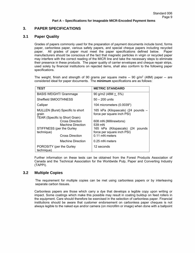
3. PAPER SPECIFICATIONS 3.1 Paper Quality
Grades of papers commonly used for the preparation of payment documents include bond, forms paper, carbonless paper, various safety papers, and special cheque papers including recycled paper. All grades of paper must meet the paper specifications defined below. Paper manufacturers should be conscious of the fact that magnetic particles in virgin or recycled paper may interfere with the correct reading of the MICR line and take the necessary steps to eliminate their presence in these products. The paper quality of carrier envelopes and cheque repair strips, used solely by financial institutions on rejected items, shall also conform to the following paper specifications.
The weight, finish and strength of 90 grams per square metre -- 90 g/m2 (48M) paper -- are considered ideal for paper documents. The minimum specifications are as follows:
TEST METRIC STANDARD
BASIS WEIGHT/ Grammage 90 g/m2 (48M + 5%)
Sheffield SMOOTHNESS 50 – 200 units
Calliper 104 micrometers (0.0039")
MULLEN (Burst) Specific to short grain
165 kPa (Kilopascals) (24 pounds – force per square inch PSI)
TEAR (Specific to Short Grain) Cross Direction Machine Direction
608 mN (Millinewtons) 539 mN
STIFFNESS (per the Gurley technique)
165 kPa (Kilopascals) (24 pounds force per square inch PSI)
Cross Direction 0.11 mN meters
Machine Direction 0.25 mN meters
POROSITY (per the Gurley technique)
12 seconds
Further information on these tests can be obtained from the Forest Products Association of Canada and the Technical Association for the Worldwide Pulp, Paper and Converting Industry (TAPPI). 3.2 Multiple Copies The requirement for multiple copies can be met using carbonless papers or by interleaving
separate carbon tissues.
Carbonless papers are those which carry a dye that develops a legible copy upon writing or impact. Some coatings which make this possible may result in coating buildup on feed rollers in the equipment. Care should therefore be exercised in the selection of carbonless paper. Financial institutions should be aware that customer endorsement on carbonless paper cheques is not always legible to the naked eye and/or camera (on microfilm or image) when done with a ballpoint

Standard 006 Page 10
Part A – Specifications for Imageable MICR-Encoded Payment Items
pen. Such items should be endorsed with a felt-tipped or fountain pen. Carbonized form sets are those which contain one or more copies having a carbon coating applied directly to the paper.
Carbon interleaved sets are no problem for automated document handling if it is only the original
document that is sorted. If a subsequent (duplicate) copy is to be sorted (as is true with the register copy of many money orders), problems in sorting may be encountered if there is an appreciable transfer of carbon to the face of the copy. There are many circumstances under which either the original copy, or one of the multiple copies from these form sets, will be encoded and therefore find its way into the payments clearing system. For that reason, the way in which the special characteristics of these papers may affect the reader-sorter function must be considered.
The use of carbon strips on the back of MICR-encoded documents is not permitted. 3.3 Document Sizes Note: In converting the Imperial measurements to Metric measurements in this Standard, some
of the Metric figures have been rounded off, in most cases to the nearest hundredth of a centimeter.
All documents, excluding any detachable portions, are to be rectangular in shape. The following
minimum and maximum dimensions shall be adhered to:
Length Depth Minimum
15.88 cm (6¼")
6.99 cm (2¾")
Maximum
21.59 cm (8½")
9.53 cm (3¾")
3.4 Business Reply Envelopes
The minimum size of documents established for the magnetic ink character recognition program is 15.88 cm x 6.99 cm (6¼" x 2¾"), and the maximum size is 21.59 cm x 9.53 cm (8½" x 3¾") Since folded documents and creases through MICR characters increase the possibility of jams, misreads and rejects in reader-sorters, it is recommended that undersized business reply envelopes not be used.
3.5 Window Envelope Documents
The window envelope cheque has been designed to meet Canadian post office standards, in that the maximum space allowed for the window is 1.91 cm (3/4") from the bottom edge of the envelope and 1.43 cm (9/16") from the right and/or left edge of the envelope and 3.97 cm (19/16") from the top edge of the envelope.
For further information on window envelope specifications refer to the Canadian Postal Standards Manual.

Standard 006 Page 11
Part A – Specifications for Imageable MICR-Encoded Payment Items
3.5.1 Window Envelope Limitations
3.6 Continuous Forms 3.6.1 Perforations - Voucher and Pin-fed Documents
To avoid processing problems due to skew caused by irregular Tears, any detachable statement should be placed to the left or at the top of the payment item. While some document issuing methods may make such a format impracticable (for example, continuous pin-fed documents) clean perforations are essential to reduce the chances of mutilating such documents. It is essential in press perforations that no magnetic ink be deposited along the bottom 1.59 cm (5/8") band or right-hand edges of documents, such as would happen with inked press perforations.
Where document alignment holes are used, as for continuous pin-fed documents, the portions containing the holes on both edges of the document are to be perforated and detachable so they can be removed from the document before it is presented for payment.
When a document contains a detachable voucher, the voucher should be attached to the top or left side of the document. Pin-fed margins on either edge of the document must be removed prior to collection. This simply emphasizes the fact that the edges of the document destined for electronic sorting should be as clean and sharp as possible. A MICR-encoded document that is accompanied by a non-detachable statement shall be considered as an item not conforming to Standard 006.
3.6.2 Guide Marks Selvedge on continuous forms should be perforated. When this is not possible, guide marks
must be provided to indicate the correct guillotining position. It is recommended that these guide marks not infringe upon the 1.59 cm (5/8") MICR band, as they introduce extraneous ink into the readable area.
However, if guide marks do appear within the 1.59 cm (5/8”) MICR band, they shall not be printed with magnetic ink.
In order to reduce to potential for interference with the MICR characters, the horizontal marks shall be printed in the corners no higher than 0.3 cm (.12”) from the bottom edge

Standard 006 Page 12
Part A – Specifications for Imageable MICR-Encoded Payment Items
of the cheque and shall extend no more than .81 cm (.32”) from the left and right edges of the cheque.
To ensure your guide marks do not encroach too far into the MICR band, it is strongly recommended that horizontal guide marks not be larger than .635 cm (.25”) in length, and that vertical guide marks not be larger than .15cm (.0575”) in height. Guide marks larger than the recommended measurements may cause interference with the reading of the MICR information which could cause a failure in testing.
3.6.3 Edge Notching Documents intended for computer sorting may not be produced with notches or other types of
indentation on any edge, as these can create equipment jams and interlocking of documents during processing.
3.6.4 Holes in Documents Because of the constraints of electronic processing equipment, holes of any shape or size in
documents are not desirable. The use of holes in any type of MICR-encoded document must be cleared with your CPA member Quality Assurance Department.
3.6.5 Detachable Borders All detachable borders (e.g., voucher stubs and perforated pin-fed margins), must be removed
before negotiation. All pin-fed borders on both edges of the document must be removable. 3.7 Cutting
If possible, documents should be left a minimum of 2-4 hours before cutting. Documents should not be allowed to sit in piles of more than 350 sheets. This means frequent attention to the delivery platform while running and short piling during the drying period. When cutting, extreme care should be exercised to make certain that the bottom and right edges of the documents are horizontal and vertical to the MICR line of characters. Otherwise, overall skew might occur and the documents may fail to meet the Standard. Furthermore, it is extremely important to cut the documents so that the MICR-encoding is properly positioned and that no guide marks or any portion thereof remain within the 1.59 cm (5/8") band of the document. Also, cut in small quantities of not more than 200-250 sheets at once.

Standard 006 Page 13
Part A – Specifications for Imageable MICR-Encoded Payment Items
4. SPECIFICATIONS FOR MICR-ENCODING 4.1 Machine Language The machine language used is type E-13B. This consists of fourteen characters. The ten digits
are:
The four symbols are:
The Transit Number Symbol, which indicates to the reader-sorter the boundaries of the Transit Field.
The On-Us Symbol, which indicates to the reader-sorter where to commence reading the Account Number or where to commence and finish reading the Serial Number Field.
The Amount Symbol, which indicates to the reader-sorter the boundaries of the amount field. Printers will not use this symbol ordinarily but it is reproduced here for recognition purposes.
The Dash Symbol, which is a divider or hyphen to the reader-sorter. Note : For technical specifications of E-13B characters and magnetic ink, see Appendix I. 4.2 MICR-Encoding Area
Following is a detailed diagram of the 1.59 cm (5/8") MICR area, an important part of the document format. There are placement specifications governing the location of the encoded characters printed in this area.
The area containing the MICR band measures 1.59 cm (5/8") from the bottom edge of the document. In the MICR band, the use of magnetic ink is restricted to the printing of the prescribed E-13B characters. No printing shall appear anywhere in this area on the face of the document except the prescribed E-13B characters in the encoding line (see section 4.4). It is strongly recommended that the MICR band remain clear of background screening. Borders are not permitted within the 1.59cm (5/8") clear MICR band.
No magnetic ink shall be printed on the reverse side of the document within the 1.59 cm (5/8") area along the bottom of the document.

Standard 006 Page 14
Part A – Specifications for Imageable MICR-Encoded Payment Items
For purposes of this Standard the right and left characters in any field are referred to as the opening and closing characters respectively.
4.3 Reference Edges
All measurements for the positioning of any element or space in the 1.59 cm (5/8") MICR-
encoding band must be taken from the right and bottom edge of the document. These edges are referred to as reference edges. These edges must form a right angle and be true in every way. All horizontal dimensions are measured from the right edge, all vertical dimensions from the bottom edge.
Exception: The left-most symbol of the left-most field must be .32 cm (1/8") or more from the left-hand edge
of the document. 4.4 Fields or Areas of the Encoding Line The band reserved for MICR printing is the 1.59 cm (5/8") area along the bottom edge of the
document, and must not contain any other printing. The lower edge of the encoding line should be at least .48 cm (3/16") above the bottom edge of
the document and parallel to that edge. The next .64 cm (1/4") above provides the area where the encoding line appears. The remaining .48 cm (3/16"), making up the 1.59 cm (5/8") MICR band, remains clear.
Whenever adjacent fields are printed at different times or using different printing techniques,
there must be a minimum of one blank space between those fields. The encoding line is divided into fields as follows: 4.4.1 Amount Field (Under normal circumstances, the printer will not be required to print in this field.)
Boundaries: No further left than 4.76cm (1⅞") from the right edge of the document. The right edge of the symbol appearing at the extreme right of this field must be .79 cm (5/16"), plus or minus .16 cm (1/16") from the right edge of the document.
SERIAL NUMBER FIELD

Standard 006 Page 15
Part A – Specifications for Imageable MICR-Encoded Payment Items
4.4.2 On-Us Field
Boundaries: 4.76 cm (17/8") from the right edge of the document, continuing left to 10.80 cm (41/4") from that edge.
Eighteen (18) spaces are allotted for this field. There is no closing on-us symbol for this field. Rather than considering the On-Us Field in terms of specific numbers of spaces, it should be viewed in terms of the maximum allowable dimensions.
If this information is printed at the same time and using the same printing technique as the Transit Number Field, the blank normally required between the On-Us and Transit Number Fields may be omitted. The On-Us Field is divided into two sections as follows:
4.4.2.1 Transaction Code Section This section deals with transaction codes applicable to imageable MICR encoded documents. Subject to the exceptions listed below, the Transaction Code Section may be blank or consist of a
maximum of four (4) digits located between the closing symbol of the amount field and the opening symbol of the Account Number Section. Where applicable, spaces should be provided to accommodate combinations of pre-encoded and post-encoded information.
Exceptions:
Transaction code "45"1 shall be encoded on all U.S. Dollar Items drawn on a U.S. Dollar account held with a member or drawn on the Canada Post Corporation, with the exception of paper Pre-Authorized Debits, Items encoded with an ABA Routing Number, and certain other U.S. Dollar Items on which a CPA Member may encode a different transaction code;
Transaction code 33 shall be encoded on Business Pre-Authorized Debits (PADs), in accordance with CPA Rule H1;
Transaction code 44 shall be encoded on Cash Management PADs in accordance with CPA Rule H1;
Transaction code 83 shall be encoded on Funds Transfer PADs where no recourse is provided in accordance with CPA Rule H1; and
Transaction code 81 may be required on Gift Certificates and Store Coupons in accordance with CPA Rule H2.
[Note: transaction code 05 is reserved for future use.]
Please see Appendix VII for a listing of all transaction codes for paper items reserved for CPA use. Consult the Quality Assurance Division of the CPA member (See Appendix V) for information on transaction codes applicable to certain categories of payment items.
1 The following Institutions are temporarily exempt from the requirement to encode transaction code 45 on U.S. Dollar items: Fédération des caisses Desjardins du Québec (currently using transaction code 11) and its members, the Credit Union Central of Nova Scotia (currently using transaction code 90) and its members, and the Central 1 Credit Union (currently using transaction codes 644 and 6404) and its members. These institutions will work towards migrating to the new transaction code on a best efforts basis as soon as possible.

Standard 006 Page 16
Part A – Specifications for Imageable MICR-Encoded Payment Items
4.4.2.2 Account Number Section Customers who have their own documents printed must obtain Account Number Section
information from their financial institution in the form of a specification sheet (see Appendix III). The Account Number must be preceded by an on-us symbol. Individual CPA members will
specify the number and positions of dash symbols and/or blanks to be used (see Appendix IV). 4.4.3 Transit Number Field
Boundaries: 10.80 cm (41/4") from the right edge of the document continuing left to 14.61 cm (53/4") from that edge.
The Transit Number Field always occupies eleven (11) spaces. All spaces in this field must be encoded. This field contains two groups of digits separated by the dash symbol. Reading from right to left, these groups are: institution number (three digits) and branch number (five digits). The Transit Number Field must open and close with a transit number symbol.
4.4.4 Serial Number Field
Boundaries: 14.61 cm (53/4") from the right edge of the document continuing left to .32 cm (1/8") from the left edge of the document.
This variable length field is used for serial numbering. The maximum number of characters is fourteen (14) -- twelve (12) digits plus two (2) on-us symbols. This field must open with an on-us symbol and close with an on-us symbol. Blanks or dashes may replace one or more of these twelve digits. The closing symbol must be adjacent to the left-most digit. The presence of a Serial Number in the Serial Number field on MICR-encoded documents is highly recommended but not mandatory.
If this information is printed at the same time and using the same printing technique as the Transit Number Field, the blank normally required between the Serial Number and Transit Number Fields may be omitted. Customers should consult their financial institution Document Quality Assurance Department (refer to Appendix V) for information regarding the format and maximum number of characters in this field.
4.5 Positioning
The minimum distances of .64 cm (1/4") ± .16 cm (1/16") from the right edge of the document and .32 cm (1/8") or more from the left edge of the document are mandatory.
Horizontal positioning is subject to plus or minus .16 cm (1/16") either left or right of the field boundaries given.
The only maximum spacing restriction is two character positions between the Transit Number Field and the Serial Number Field.
Exception: Floating Fields -- If the length of the document is such that there is insufficient space to print the Serial Number Field, then the On-Us, Transit Number, and Serial Number Fields may be shifted to the right. The maximum right shift allowed is such that the opening character of the On-Us
Standard 006 Page 17
Part A – Specifications for Imageable MICR-Encoded Payment Items
Field will remain within its defined boundaries. This exception does not negate the standard that whenever adjacent fields are printed at different times or using different printing techniques, there must be a minimum of one blank space between those fields. Customers must not use floating fields without the prior consent of their financial institution's MICR Quality Assurance Department (see Appendix V).
4.5.1 Alignment
The alignment of the bottom edge of any two adjacent numerical MICR characters must not vary more than 0.018 cm (.007") except between fields.
4.5.2 Character and Line Skew
The maximum skew or tilt of any character or line cannot be more than 11/2 degrees off vertical using the bottom edge of the document as a horizontal reference.
4.5.3 Spacing Requirements
The distance between the right average edges of adjoining characters is .318 cm (.125"), plus or minus .025 cm (.010") in the Transit Number and Amount Fields.
In the On-Us and Serial Number Fields, and between adjoining fields, the distance between right average edges can never be less than .292 cm (.115").

Standard 006 Page 18
Part A – Specifications for Imageable MICR-Encoded Payment Items
5. SPECIFICATIONS FOR IMAGEABLE MICR-ENCODED CHEQUES 5.1 Background Screening Printed background screening or designs anywhere on the front and back of imageable MICR-
encoded documents shall be of a colour and a pattern which will not interfere with the legibility of any information, either printed or written, on the original document, or any reproduction of it through use of microfilm, imaging or photocopying equipment.
The minimum Print Contrast Signal of pre-printed data on the front of a MICR-
encoded document shall be 0.60 with respect to its immediate surrounding background. Printing of this data should be done with black or dark ink.
It is strongly recommended that light pastel colours or standard safety tints be used for
background screening and that clay "inorganic" and highly reflective inks, heavy inking and dark colours be avoided.
Printed information should appear in the specified locations, and the 1.59 cm (5/8")
band must be used only for E-13B characters. Borders are not permitted within the 1.59cm (5/8") clear MICR band.
Plain, safety tinted, and patterned documents all have backgrounds consisting of one colour or
may have a background design or pattern intended to protect against alteration. These documents are produced by a variety of methods using different ink colours, different screen values and/or ink colours to achieve a solid background colour, design, or pattern.
Scenic cheques have a background scene or picture. Different screen values and ink colours are
used to achieve the background scene or picture. Most scenic designs are printed using three or four Colour Separation processes at screening densities of 4.7 lines/mm (120 lines/inch) or greater.
If documents with screened backgrounds are desired, wide variances of ink colours and screen densities are available that could obtain the required Reflectance and PCS values. Screens in the area of 10%, 4.7 to 5.9 lines/mm (120 to 150 lines/inch) have been found to work successfully with some ink colours for the Convenience Amount Rectangle, the Convenience Amount Clear Area and the Date Field, while screens in the area of 20%, 4.7 to 5.9 lines/mm (120 to 150 lines/inch) have been used satisfactorily in the Convenience Amount Rectangle outline. The main concern for any combination of inks and screening is that the PCS for the final product shall not be exceeded while at the same time the minimum background Reflectance shall be exceeded. For scenic cheques, scenes should be muted with soft edges having gradual Reflectance changes where they intersect with Data Elements and their areas of interest. It has been found that PCS measurements are not adequate or appropriate to determine precisely what remains in a binary (black and white) image. PCS can predict scanner performance only in a very localized area with absolutely uniform background. Most documents, however, have a continuously varying background and require a more dynamic approach, such as used in industry reader sorter scanners. Furthermore, PCS will not predict to what degree Background Clutter in a Binary Image will constitute a threat to legibility of handwritten data. However, actual Binary Images, termed Dynamic Contrast Images in their generic form, can be used for this evaluation.
Refer to Section 5.4.4 for additional information on Dynamic Contrast Images.
5.2 Security

Standard 006 Page 19
Part A – Specifications for Imageable MICR-Encoded Payment Items
Any security features, including pantographs and void pantographs, that are to be applied to the front of an imageable MICR-encoded cheque or other payment item must not interfere with any of the following areas, prior to imaging or post-imaging:
the 1.59cm (5/8") MICR clear band; the date field; the payee name; the amount in figures field (i.e. the convenience amount rectangle and the dollar sign); the amount in words field; the CPA member name; and the signature area.
Any security features, including pantographs and void pantographs, that are to be applied to the back of an imageable MICR-encoded cheque or other payment item must not interfere with the following areas, prior to imaging or post-imaging:
the teller stamp box; the endorsement area; the “Verification Phrase” (i.e. “Back/Endos”; “Endos/Back”; “Back/Verso”; “Verso/Back”;
“Verso”; or “Back”); and the 2.54 cm (1”) area from the aligning edge.
For further clarity, if wording included in a security feature (e.g. null, void, cancelled, invalid) is displayed and results in uncertainty regarding the validity of an item, the item may be considered invalid and may be subject to return.
5.3 Populating the Data Elements Computer-Generated Payor Filled Fields
Systems that use computer software to populate the mandatory Date Elements or the
Legal Amount shall utilize fonts for these fields which are no less that 10 point in size (see Figure A) and shall use image-friendly inks: black, blue or dark purple.
Slanted and/or italicized formats of these fonts should not be used.
In the event a proportional spaced font is used, the design of the font shall not cause the
characters to be tightly spaced so that the recognition system cannot easily separate each character.
In no case shall the amount be printed using a reverse font where the background of the
printing is black and the character itself is not printed. Inverse printing shall not be used for printing in any areas of interest (as defined in Sub-Section 2.2)
Asterisks may be used in the convenience amount rectangle and shall only be printed
immediately preceding the amount in figures (i.e., $*****45.00 or *****45.00$). The use of asterisks in any other position in the convenience or payable amount field is not permitted.
Asterisks may be used in the legal amount field (i.e. amount in words) and shall only be
printed to the left of the amount in words (i.e. *******forty-five dollars). The use of asterisks in any other position in the legal amount field is not permitted.
Symbols other than asterisks are not permitted in the convenience amount rectangle.

Standard 006 Page 20
Part A – Specifications for Imageable MICR-Encoded Payment Items
Hand-Printed and Hand-Written Payor Filled Fields
Black or blue ball point or roller pens shall be used for populating the Data Elements of a MICR-encoded document.

Standard 006 Page 21
Part A – Specifications for Imageable MICR-Encoded Payment Items
FIGURE A – FONT SIZE SPECIFICATIONS

Standard 006 Page 22
Part A – Specifications for Imageable MICR-Encoded Payment Items
5.4 Specifications for Cheque Design 5.4.1 Front of Cheque Layout
The following examples illustrate the most common cheque layouts for personal and business cheques.
FIGURE B –TYPICAL CHEQUE LAYOUT FOR PERSONAL SIZE CHEQUE
Standard 006 Page 23
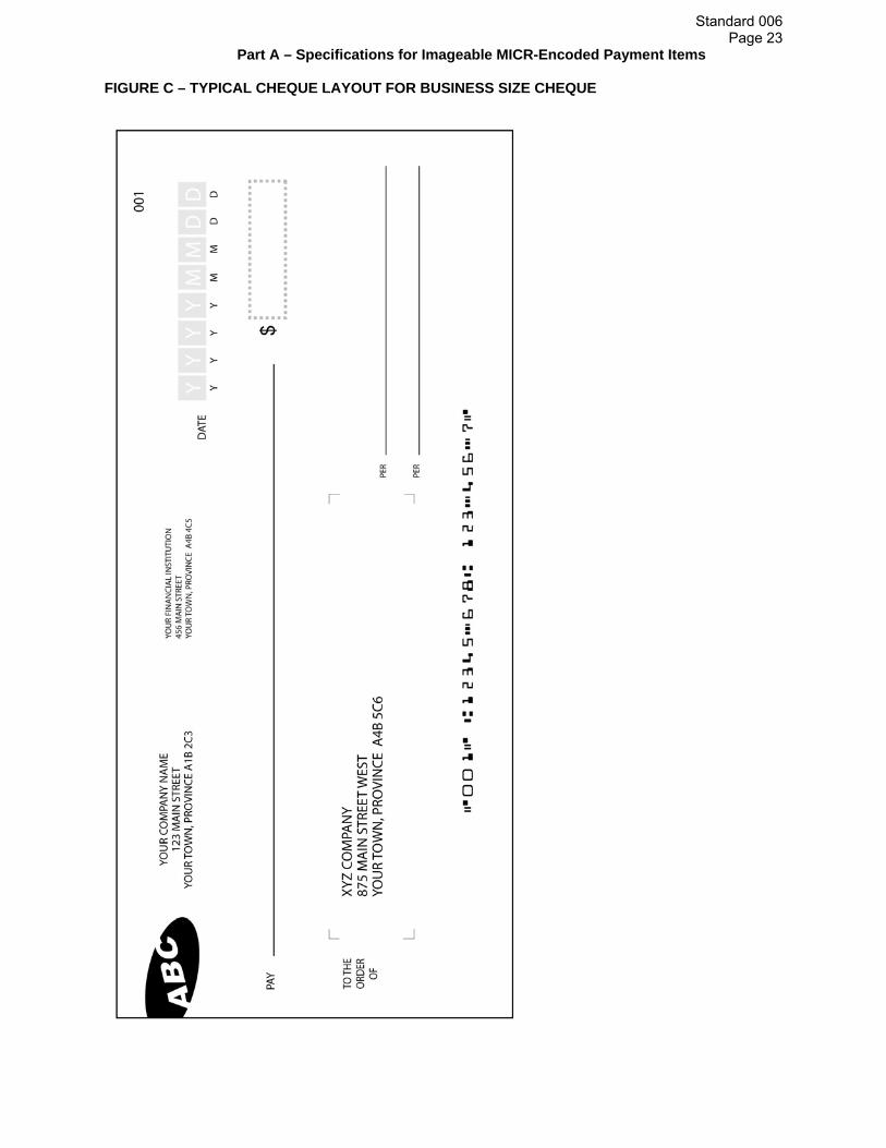
Part A – Specifications for Imageable MICR-Encoded Payment Items FIGURE C – TYPICAL CHEQUE LAYOUT FOR BUSINESS SIZE CHEQUE

Standard 006 Page 24
Part A – Specifications for Imageable MICR-Encoded Payment Items
FIGURE D – LAYOUT GUIDE

Standard 006 Page 25
Part A – Specifications for Imageable MICR-Encoded Payment Items 1) Name of CPA Member. The CPA Member name is mandatory and the type size shall be a
minimum of 6 point (see Figure A). The minimum Print Contrast Signal of this information on the front of a cheque shall be 0.60 with respect to its immediate surrounding background and shall be done with black or dark ink.
2) Branch Street Address (optional). If printed, it must be located under (1), in a minimum of 6
point (see Figure A). The minimum Print Contrast Signal of this information on the front of a cheque shall be 0.60 with respect to its immediate surrounding background and shall be done with black or dark ink.
3) Town or City, Province or Postal Code of Civic Address (optional). Located under (2),
and set in minimum of 6 point type size (see Figure A). The minimum Print Contrast Signal of this information on the front of a cheque shall be 0.60 with respect to its immediate surrounding background and shall be done with black or dark ink.
4) Cheque Number (optional). The cheque number normally appears on the extreme right of
the cheque above the date field; however, positioning is flexible provided it does not interfere with a data element or its area of interest. The minimum Print Contrast Signal of this information on the front of a cheque shall be 0.60 with respect to its immediate surrounding background and shall be done with black or dark ink.
5) MICR-Encoding Area. The 1.59 cm (5/8") deep area across the bottom edge of the cheque.
6) Date Field. The date field includes the word “DATE”, guidance boxes and characters, and the
date field indicators.
The date field is to be located towards the upper right edge of the cheque. It shall be located to provide at least 0.64 cm (¼") clearance with respect to the convenience amount rectangle to prevent manual extraneous date completion from entering the convenience amount clear area.
If other information (e.g. town/city/province line) is printed on the same level to the left of
the date field, at least 1.91 cm (3/4”) of space shall separate that printing and the word “DATE” at the beginning of the date field.
The word “DATE” shall be in a minimum of 8 point font. See Figure A.
The date field shall be designed in such a way as to encourage a standardized, numeric
representation of the date. Acceptable numeric representation for the date field on all cheques is in the form of YYYYMMDD, MMDDYYYY and DDMMYYYY.
Spaces, dashes or dots are permitted between elements of the date (e.g. 2005 09 23;
23-09-2005; or 09.23.2005).
Slashes or other symbols are NOT permitted between elements of the date. (Note: Slashes are permitted in the bilingual version of the date field indicators, which must be printed below the date as shown in Figure E1).
Field Indicators (min 6 pt font and max 8 pt font) shall be printed below the
guidances boxes (or date if the date field is filled using an automated process) on all cheques in order to indicate which numeric date format is used. Refer to Figure E.
The Reflectance of the date Area of Interest shall be at least 40%.
Standard 006 Page 26
Part A – Specifications for Imageable MICR-Encoded Payment Items
The Field Indicators shall be printed such that the PCS of the Field Indicators with respect to the background is at least 0.60.
For cheques on which the date will be written by hand or completed using a manual
process (e.g. using a typewriter), guidance boxes must be printed in the Area of Interest to encourage numeric representation of the date, as illustrated in Figure E. As an option, guidance characters (minimum 10 pt font) may appear within the guidance boxes to indicate the numeric format to be used.
Both the guidance boxes and the guidance characters inside them are optional on
cheques for which the date field will be filled using an automated process.
On cheques using Date Field Guidance Boxes and Guidance Characters, they shall be printed such that the boxes do not appear in a black and white image of the item. Therefore, the boxes shall have a maximum PCS of 0.30 with respect to the background of the Date Field Area of Interest.

Standard 006 Page 27
Part A – Specifications for Imageable MICR-Encoded Payment Items
FIGURE E – DATE FIELD DESIGN (Not to scale)
If the date is printed using the International Date Format (YYYYMMDD), a bilingual version of the field indicators is also permissible. The format shall be as follows: Y/A M/M D/J or A/Y M/M J/D (see figure E1).

Standard 006 Page 28
Part A – Specifications for Imageable MICR-Encoded Payment Items
FIGURE E1 – BILINGUAL DATE FIELD INDICATOR DESIGN – (not to scale)
7) Payee Name Field. The payee name is generally located in the mid-section of the cheque.
On cheques to be completed manually, the right end limit of the payee line shall be truncated with a vertical line as shown in Figure B and shall not interfere with the Amount in Figures field. The payee name may appear below the Amount in Words Field (see Figure C) to accommodate the requirements of the payee name and address to appear in a window envelope.
8) Convenience Amount Rectangle (Amount in Figures). The Convenience amount
rectangle is preceded or followed by a dollar sign, and shall be located at the extreme right either on the same line as the payee (see Figure B), or, in order to accommodate the requirements of the Payee name and address to appear in a window envelope, the Amount in Words may appear on the same line as the Amount in Figures on a business size cheque (see Figure C).
Only one amount in figures shall appear within the Convenience Amount Scan
Area.
Alphabetic characters are not permitted in this area. 9) Amount in Words (Legal Amount). On most cheques, the amount in figures is repeated as a
handwritten or machine printed text line.
On a personal cheque, the line for this element should be located to the left of the amount in figures area and below the line for name of the payee.
If the payee name and address are to appear in a window envelope (see Figure C), this
information may be located above the payee name.
On cheques where the amount in words is to be completed manually, it is recommended that this line end with the word “DOLLARS” or that “DOLLARS” be printed just below the line at the end of the amount in words, ensuring that the 0.64 cm (0.25”) clear area is maintained around the Convenience Amount Rectangle and the Dollar Sign.
On cheques where the amount in words is machine printed, the line may end with the word
“Dollars” in the position described above, or with either “Dollars” or “Cents” integrated into the machine printed amount in words.
It is highly recommended but not mandatory to provide the Amount in Words on cheques.

Standard 006 Page 29
Part A – Specifications for Imageable MICR Encoded Payment Items
10) Signature Line Area. The signature line area should be located in the lower right area of the cheque. There can be one, or more than one required signature. Any signature line(s) shall be contained within this location so as to not interfere with the 1.59 cm (5/8") space at the bottom of the cheque allotted to MICR or the Amount in Figures Field.
11) Currency designation (e.g. CDN Funds, U.S. Funds or U.S. Dollars). A currency
designation is required on all US Dollar cheques drawn on a domestic branch of a CPA member and encoded with a Canadian transit number. The currency designation is to appear to the right of or below the word “Dollars”, not interfering with any areas of interest. On cheques where the word “Dollars” is integrated into the machine-printed Amount in Words, the currency identifier (e.g. U.S. Funds) may be printed below the Convenience Amount Rectangle, leaving a minimum 0.64 cm (1/4”) of clear space between the bottom of the Convenience Amount Rectangle and the currency identifier. A currency identifier is not permitted to be printed beside the Amount in Figures.
Note: “Payable through U.S. Dollar” items are subject to additional specifications, the details of which are outlined below. “Payable through U.S. dollar items” are those items, which are payable in U.S. funds, drawn on a domestic branch of a CPA member and payable through that member’s U.S. agency or correspondent relationship. In addition to complying with the specifications outlined in this standard, the following information is required for “payable through” items: a) “Payable through” line; i.e., U.S. bank branch/office and address; b) Name, address, and 8-digit transit number of Canadian drawee branch; c) U.S. Funds or U.S. Dollars or U.S$ or USD; and d) the American Bankers Association (ABA) transit routing number assigned by/to the “payable
through” bank. This number must be printed in the Transit Number Field in the MICR line and is generally printed, in a fractional format (X-XXX/XXX), in the upper right corner of the item. The fractional routing number may, however, be omitted at the option of the drawee institution.
12) Payor Name and Address. It is highly recommended that the Payor's name appear on cheques. The Payor's address is optional.
Informational Printing on the Front of Documents. Informational Printing refers to any additional printing that the cheque issuer or printer includes on the cheque (i.e. on the front of the cheque, printing other than the MICR line and the elements outlined in paragraphs 1-12 above). Informational Printing on the front of imageable MICR-encoded documents shall be of a colour and placement which will not interfere with any Areas of Interest on the original document, or on an image, photocopy or microfilm representation of the document. If the information is intended to be visible on an image, it should have a minimum Print Contrast Signal of 0.60.
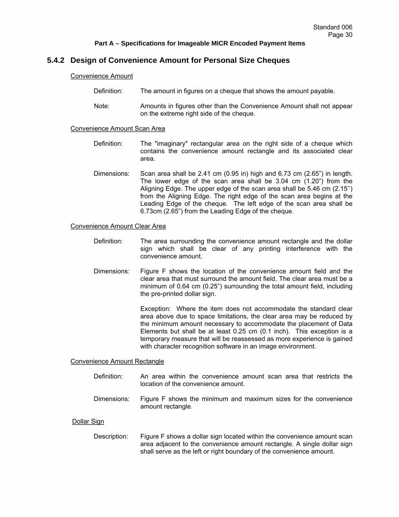
Standard 006 Page 30
Part A – Specifications for Imageable MICR Encoded Payment Items
5.4.2 Design of Convenience Amount for Personal Size Cheques Convenience Amount
Definition: The amount in figures on a cheque that shows the amount payable. Note: Amounts in figures other than the Convenience Amount shall not appear
on the extreme right side of the cheque.
Convenience Amount Scan Area Definition: The "imaginary" rectangular area on the right side of a cheque which
contains the convenience amount rectangle and its associated clear area.
Dimensions: Scan area shall be 2.41 cm (0.95 in) high and 6.73 cm (2.65”) in length.
The lower edge of the scan area shall be 3.04 cm (1.20”) from the Aligning Edge. The upper edge of the scan area shall be 5.46 cm (2.15’’) from the Aligning Edge. The right edge of the scan area begins at the Leading Edge of the cheque. The left edge of the scan area shall be 6.73cm (2.65”) from the Leading Edge of the cheque.
Convenience Amount Clear Area
Definition: The area surrounding the convenience amount rectangle and the dollar sign which shall be clear of any printing interference with the convenience amount.
Dimensions: Figure F shows the location of the convenience amount field and the
clear area that must surround the amount field. The clear area must be a minimum of 0.64 cm (0.25”) surrounding the total amount field, including the pre-printed dollar sign.
Exception: Where the item does not accommodate the standard clear area above due to space limitations, the clear area may be reduced by the minimum amount necessary to accommodate the placement of Data Elements but shall be at least 0.25 cm (0.1 inch). This exception is a temporary measure that will be reassessed as more experience is gained with character recognition software in an image environment.
Convenience Amount Rectangle
Definition: An area within the convenience amount scan area that restricts the location of the convenience amount.
Dimensions: Figure F shows the minimum and maximum sizes for the convenience
amount rectangle.
Dollar Sign
Description: Figure F shows a dollar sign located within the convenience amount scan area adjacent to the convenience amount rectangle. A single dollar sign shall serve as the left or right boundary of the convenience amount.

Standard 006 Page 31
Part A – Specifications for Imageable MICR Encoded Payment Items
Location: The dollar sign shall be perpendicular to the Aligning Edge and centred +/- 0.038 cm (0.015”) vertically on the convenience amount rectangle. The dollar sign shall be a minimum of 0.076 cm (0.03”) and a maximum of 0.127 cm (0.05”) to the left or right of the convenience amount rectangle.
Design: The dollar sign shall be a continuous printed character with one unbroken
vertical line close to the centre of the sign. The dollar sign shall be printed in a minimum 10 point font; it shall not be printed using an italicized or slanted font type. To provide adequate visual and machine recognition of the convenience amount, the sign shall be printed in a colour that provides a PCS of 0.60 or greater with respect to its background. The usual colour for the dollar sign is black.
Note: Example A (not to scale) shows a correct dollar sign with an unbroken vertical line. Example B is incorrect.

Standard 006 Page 32
Part A – Specifications for Imageable MICR Encoded Payment Items
FIGURE F - CONVENIENCE AMOUNT CLEAR AREA AND CONVENIENCE AMOUNT RECTANGLE FOR PERSONAL CHEQUES (not to scale)
Note: The Convenience Amount Rectangle and its Clear Area must fall within the scan area.
5.4.3 Design of Convenience Amount Field for Business Size Cheques
Business cheques may use a larger form size than the standard personal cheque to accommodate all necessary information.
Convenience Amount
Definition: The amount in figures on a cheque that shows the amount payable. Note: Amounts in figures other than the Convenience Amount shall not appear on the
extreme right of the cheque.
Convenience Amount Scan Area
Definition: The “imaginary” rectangular area on the right side of the cheque which contains the convenience amount rectangle and its associated clear area.

Standard 006 Page 33
Part A – Specifications for Imageable MICR Encoded Payment Items
Dimensions: The area shall be 3.94 cm (1.55”) high and 6.73 cm (2.65”) in length. The lower edge of the scan area shall be 3.04 cm (1.2”) from the Aligning Edge. The upper edge of the scan area shall be 6.98 cm (2.75”) from the Aligning Edge. The right edge of the scan area begins at the Leading Edge of the cheque. The left edge of the scan area shall be 6.73 cm (2.65”) from the Leading Edge of the cheque.
Convenience Amount Clear Area
Definition: The area surrounding the convenience amount rectangle which shall be clear of any printing interference with the convenience amount.
Dimensions: Figure G shows the location of the convenience amount field and the clear area
that must surround the amount field. The clear area must be a minimum of 0.64 cm (0.25”) surrounding the total amount field, including the pre-printed dollar sign. Exception: Where the item does not accommodate the standard clear area above due to space limitations, the clear area may be reduced by the minimum amount necessary to accommodate the placement of Data Elements but shall be at least 0.25 cm (0.1 inch). This exception is a temporary measure that will be reassessed as more experience is gained with character recognition software in an image environment.
Convenience Amount Rectangle
Definition: An area within the convenience amount scan area that restricts the location of the convenience amount.
Dimensions: Figure G shows the minimum and maximum sizes for the convenience amount
rectangle. Dollar Sign
Description: Figure G shows a dollar sign located within the convenience amount scan area adjacent to the convenience amount rectangle. A single dollar sign shall serve as the left or right boundary of the convenience amount.
Location: The dollar sign shall be perpendicular to the Aligning Edge and centered +/-0.038
cm (0.015”) vertically on the convenience amount rectangle. The dollar sign shall be a minimum of 0.076 cm (0.03”) and a maximum of 0.127 cm (0.05”) to the left or right of the convenience amount rectangle.
Design: The dollar sign shall be a continuous printed character with one unbroken
vertical line close to the centre of the sign. The dollar sign shall be printed in a minimum of 10 point font; it shall not be printed using an italicized or slanted font type. To provide adequate visual and machine recognition of the convenience amount, the sign shall be printed in a colour that provides a PCS of 0.60 or greater with respect to its background. The usual colour for the dollar sign is black.

Standard 006 Page 34
Part A – Specifications for Imageable MICR Encoded Payment Items
Note: Example A (not to scale) shows a correct dollar sign with an unbroken vertical line. Example B is incorrect.
FIGURE G - CONVENIENCE AMOUNT CLEAR AREA AND CONVENIENCE AMOUNT RECTANGLE FOR BUSINESS CHEQUES (not to scale)
Note: The Convenience Amount Rectangle and its Clear Area must fall within the scan area.

Standard 006 Page 35
Part A – Specifications for Imageable MICR Encoded Payment Items
5.4.4 Reflectance, Paxel Count and Print Contrast Signal (PCS) Specifications for Cheques
Two distinct calculations for Reflectance are used in this Standard:
a) Background Reflectance is used in conjunction with PCS Determination and applies to
the background of the cheque within the convenience amount rectangle, the convenience amount clear area, and the MICR optical clear band. It is determined by manual selection of sample regions, which are interpreted as Abackground@ by the operator. The visual effect of the background can be a plain or single colour, a traditional safety paper, a printed pattern, a muted scene, or a muted picture.
b) Average Area Reflectance uses all the Pixels in an area and is used for legibility analysis.
It refers to the background in the Areas of Interest. The Average Area Reflectance is calculated as the average of all Pixels in each 0.318 cm x 0.318cm (0.125”x 0.125”) square in the Area of Interest being measured.
Paxel Count in this specification refers to the automatic analysis of a Dynamic Contrast Image (DCI) in any of the areas of interest. It is derived from counting the clusters of black Pixels, termed Paxels, remaining in a DCI created using a Dynamic Contrast Ratio of 0.20. The limit of Paxel Count is the number of contiguous Paxels that, when joined in any shape, line or combination can create Background Clutter that can affect the legibility of handwritten data. PCS in this specification refers to the ratio of the Reflectance of a particular printed point with respect to the Reflectance of the background region immediately surrounding the printed point. These specifications target dropout of non-essential features in Binary Images, ensure that essential data does not drop out, and ensure legibility of handwritten data over background patterns. Manual Reflectance measurements can be made taking multiple samples within the specific area. Reflectance and PCS calculations shall be made using the average Reflectance measurements from a colour measurement system having a circular aperture of 0.020 cm (0.008”). This method of measuring background Reflectance assumes that the background in these areas is relatively uniform. Otherwise a large number of samples must be taken in the area to determine its representative background Reflectance reliably. PCS is calculated by measuring the Reflectance of a candidate pattern (relatively darker areas within the background) as Rp. The measurement of Rb from the local background is used to compute:
PCS = (Rb-Rp)/Rb.
Where Rp is the Reflectance of the point of interest, and Rb is the background (or surrounding) Reflectance.
Refer to Appendix II of this standard for additional quality assurance testing information. Measurements in the Areas of Interest (AOI) should be made assuming that the user data are contained in horizontally oriented rectangles having a height of 0.635 cm (0.250”) and having a length equal to the line length for each field, but not including the line.

Standard 006 Page 36
Part A – Specifications for Imageable MICR Encoded Payment Items
The Background Reflectance and PCS measurements for cheques must adhere to the specifications in Table 1, provided below.
TABLE 1 - SPECIFICATIONS FOR CHEQUE DATA ELEMENTS AREA ON A CHEQUE
REFLECTANCE MAX PAXEL
COUNT ** PCS NOTES
Front of Cheque
Legal AOI 40% avg. min.* 12 N/A within AOI
Payee AOI
40% avg. min.* 12 N/A within AOI
Signature AOI
40% avg. min.* 12 N/A within AOI
Date AOI
40% avg. min.* 12 N/A within AOI
CA rectangle area
60% min 0.30 max PCS w/n rectangle area
CA clear area
60% min 0.30 max PCS w/n the clear area
CA rectangle outline
N/A 0.30 max PCS wrt internal area
Dollar Sign
0.60 min
MICR Clear Band Area
60% min
0.30 max
PCS w/n MICR clear band background
MICR Characters
N/A
0.60 min
PCS wrt MICR clear band background
Date Field Guidance Boxes***
N/A
0.30 max
PCS wrt background
Date Field Guidance Characters***
N/A
0.30 max
PCS wrt to internal area of Date AOI
Date Field Indicators***
N/A
0.60 min
PCS wrt background
*To ensure that Reflectance does not drop below 40% in the manufacturing process, a design minimum target value of 43% is recommended. **Refer to Sub-Section 2.18 for additional information. ***Refer to paragraph 5.4.1 clause 6.

Standard 006 Page 37
Part A – Specifications for Imageable MICR Encoded Payment Items
TABLE 1 - SPECIFICATIONS FOR CHEQUE DATA ELEMENTS
AREA ON A CHEQUE
REFLECTANCE
MAX PAXEL
COUNT **
PCS
NOTES
Reverse Side of a Cheque
Informational Printing
If the information is intended to be visible on an image, it should have a minimum PCS of 0.60 and cannot interfere with any areas of interest.
“Teller Stamp Here Box” containing the phrase “Teller Stamp Here”
0.25 max
Endorsement Line and phrase “Endorsement – Signature or Stamp”
0.60 min
Verification Phrase
(i.e. “Back/Endos”; “Endos/Back”; “Back/Verso”; “Verso/Back”; “Verso”; or “Back”)
0.60 min
Bottom 2.54 cm (1”)
0.25 max
Optional Informational Printing
Abbreviations: CA = convenience amount AOI = Area Of Interest wrt = with respect to w/n = within N/A = not applicable

Standard 006 Page 38
Part A – Specifications for Imageable MICR Encoded Payment Items
5.4.5 Reverse Side of a Cheque
FIGURE H - CANADIAN PAYMENTS ASSOCIATION STANDARD LAYOUT FOR THE REVERSE SIDE OF A CHEQUE (NOT TO SCALE)
Note: Any printing in the bottom 2.54 cm (1”) of the back of the cheque is to have a maximum PCS of 0.25. Inverse printing, where the background of the printing is black and the character itself is not printed, shall not be used.
1) The "Teller Stamp Here" box shall be located in the upper left hand corner on the reverse side of the cheque. It should be situated .317 cm (⅛") in from the top of the cheque and .317 cm (⅛") in from the left side. It shall contain the phrase "Teller Stamp Here" in a font size no larger than 6 point with a maximum PCS of 0.25. The box shall be a maximum of 6 cm (2 d") high by 6 cm (2d") wide and a minimum of 3.5 cm (1d") high by 4.1 cm (1e") wide printed in a maximum PCS of 0.25.
2) The endorsement area includes the signature or stamp line(s) and/or address line(s)
(where applicable). It shall begin 8.89cm (3.5") from the leading edge of the cheque. It shall be placed no lower than 3.81 cm (1.5") from the aligning edge (i.e. bottom) and shall end at least 1.27cm (½”) away from the right hand edge. It shall be underscored by the phrase "Endorsement - Signature or Stamp" in an 8 point font. The minimum Print Contrast Signal of this phrase shall be 0.60 with respect to its immediate surrounding background. Printing of this phrase shall be done with black or dark ink.
3) A Verification Phrase shall be printed 8.89cm (3.5") from the Leading Edge and 2.54cm
(1") from the Aligning Edge in a font no less than 10pt in size. The Verification Phrase shall consist of the words “BACK/ENDOS”; “ENDOS/BACK”; “BACK/VERSO”; “VERSO/BACK”; “BACK”; or “VERSO”. The minimum Print Contrast Signal of this phrase

Standard 006 Page 39
Part A – Specifications for Imageable MICR Encoded Payment Items
shall be 0.60 with respect to its immediate surrounding background. This phrase shall be printed in black or dark ink.
Informational Printing on Back of Documents Informational printing on the back of a MICR-encoded document refers to any printing other than the three required elements described above. Any informational printing shall be of a colour and placement which will not interfere with the legibility of those Areas of Interest or any CPA–member required endorsements or identifiers on the original document, or on an image, photocopy or microfilm representation of the document. Any informational printing in the bottom 2.54 cm (1”) on the back of the MICR-encoded document will have a maximum PCS of 0.25.
If the informational printing is intended to be visible on the image, it should be printed in a minimum PCS of 0.60 in the upper right corner, ensuring sufficient space is left for the endorsement signature.

Standard 006 Page 40
Part A – Specifications for Imageable MICR Encoded Payment Items
6. OTHER IMAGEABLE MICR-ENCODED DOCUMENTS
All items listed in Section 6 must be in compliance with Standard 006, Part A, “Specifications for Imageable MICR-Encoded Documents” as of December 31, 2007.
6.1 Money Orders and Bank Drafts
Money Orders and Bank Drafts must comply with all specifications found in sections 3 through 5 of Standard 006, Part A.
6.2 Inter-Member Debits
Subject to the following paragraphs, Inter-Member Debits must comply with all specifications found in sections 3 through 5 of Standard 006, Part A.
The following data elements are mandatory for Inter-Member debits:
Front of the Item:
the amount in figures field; the date field; the issuing CPA member name and address (address may be pre-printed or branch staff
may complete by hand); and the 1.59cm (5/8”) MICR encoding area.
Back of the Item: the Verification Phrase; and the 2.54cm (1”) area from the aligning edge.
The following data elements are not required for Inter-Member debits:
Front of the Item:
the payee name field; and the signature line area.
Back of the Item:
the “Teller Stamp Here Box”; and the endorsement area.
The following data elements, if present, must comply with the specifications found in Standard 006, Part A:
cheque number field; and the amount in words field.
Figure I illustrates a typical design for an Inter-Member Debit.

Standard 006 Page 41
Part A – Specifications for Imageable MICR Encoded Payment Items
FIGURE I – INTER-MEMBER DEBIT
CPA Member name and branch address. Area to indicate the member branch that issued the debit. Date Field. Free Format Area to be used at the discretion of members to indicate the details of the item (e.g.
to indicate member branch to be debited, authorized staff signatures/initials, branch number and institution number of the member to be debited, etc.) Information in this area must not interfere with a mandatory data element or its Area of Interest, and should appear in a minimum PCS of 0.60 if intended to be visible on the image.
Convenience Amount Rectangle. 1.59 cm (5/8”) MICR encoding area. 6.3 Settlement Vouchers
Settlement Vouchers must comply with all specifications found in sections 3 through 5 of Standard 006, Part A.
The following data elements are mandatory for Settlement Vouchers:
Front of the Item: the payee name field; the amount in figures field; the date field; the signature line area; the CPA member name and address (address may be pre-printed or branch staff may
complete by hand); and the 1.59cm (5/8”) MICR encoding area. Back of the Item: the “Teller Stamp Here Box”; the endorsement area; the Verification Phrase; and the 2.54cm (1”) area from the aligning edge.

Standard 006 Page 42
Part A – Specifications for Imageable MICR Encoded Payment Items
The following data elements, if present, must comply with the specifications found in Standard 006, Part A: cheque number field; and the amount in words field.
Figure J illustrates the typical design for the front of a Settlement Voucher. (For an illustration of the reverse side of a typical Settlement Voucher, please refer to the sample layout for the reverse side of a cheque in Figure H in section 5.4.5.)
FIGURE J – SETTLEMENT VOUCHER
CPA Member name and address. Area to indicate the member branch that issued the settlement voucher. Voucher Number (optional). Area to indicate the serial number of the settlement voucher. Date Field. Free Format Area to be used at the discretion of members to indicate the details of the item (e.g.
mailing address, authorized signatures/initials, explanation for settlement, etc). The following required data elements must appear within the free format area:
payee name field; and the signature area.
Other information in this area must not interfere with a required data element or its Area of Interest, and should appear in a minimum PCS of 0.60 if intended to be visible on the image.
Convenience Amount Rectangle. 1.59 cm (5/8”) MICR encoding area. 6.4 Canada Savings Bonds
Subject to the following paragraphs, Canada Savings Bonds must comply with all specifications found in sections 3 through 5 of Standard 006, Part A.
The following data elements are mandatory for Canada Savings Bonds:
Front of the Item:
the payee name field; the amount in figures field; the signature line area;

Standard 006 Page 43
Part A – Specifications for Imageable MICR Encoded Payment Items
the CPA member name; and the 1.59 cm (5/8”) MICR encoding area.
Back of the Item: the “Teller Stamp Here Box”; the endorsement area; the Verification Phrase; and the 2.54 cm (1”) area from the aligning edge.
The following data elements, if present, must comply with the specifications found in Standard 006, Part A:
cheque number field; the amount in words field; and the date field.
6.5 Provincial Savings Bonds
Subject to the following paragraphs, Provincial Savings Bonds must comply with all specifications found in sections 3 through 5 of Standard 006, Part A.
The following data elements are mandatory for Provincial Savings Bonds:
Front of the Item:
the payee name field; the amount in figures field; the signature line area; the CPA member name; and the 1.59 cm (5/8”) MICR encoding area.
Back of the Item: the “Teller Stamp Here Box”; the endorsement area; the Verification Phrase; and the 2.54 cm (1”) area from the aligning edge.
The following data elements, if present, must comply with the specifications found in Standard 006, Part A:
cheque number field; the amount in words field; and the date field.
6.6 Canada Post Money Orders
Subject to the following paragraphs, Canada Post Money Orders must comply with all specifications found in sections 3 through 5 of Standard 006, Part A.
The following data elements are mandatory for Canada Post Money Orders:
Front of the Item:
the payee name field; the amount in figures field; and

Standard 006 Page 44
Part A – Specifications for Imageable MICR Encoded Payment Items
the 1.59 cm (5/8”) MICR encoding area.
Back of the Item: the “Teller Stamp Here Box”; the endorsement area; the Verification Phrase; and the 2.54 cm (1”) area from the aligning edge.
The following data elements, if present, must comply with the specifications found in Standard 006, Part A:
cheque number field; and the amount in words field.
6.7 Gift Certificates and Store Coupons
Subject to the following paragraphs, Gift Certificates and Store Coupons (as defined in CPA Rule H2) must comply with all the specifications found in sections 3 through 5 of Standard 006, Part A.
The following data elements are mandatory for Gift Certificates and Store Coupons:
Front of the Item
amount in figures field (i.e. the convenience amount rectangle and the dollar sign); CPA member name; 1.59cm (5/8”) MICR encoding area; and
Back of the Item “teller stamp here” box; endorsement area; Verification Phrase (i.e. “Back/Endos”; “Endos/Back”; “Back/Verso”; “Verso Back”; “Verso”; or
“Back”); and the 2.54 cm (1”) area from the aligning edge. The following data elements, if present, must comply with the specifications found in sections 3 through 5 of Standard 006, Part A: payee name field; amount in words field; date field; gift certificate or store coupon number (see cheque number); and signature line area. Exceptions and Additional Requirements: Transaction code: In accordance with CPA Rule H2, Financial Institutions require an
automated means to identify Gift Certificates and Store Coupons. Transaction Code 81 may therefore be required by some Financial Institutions. (Note: issuers of Gift Certificates and Store Coupons should contact their Financial Institution for more information in this regard).
A phrase to identify the type of item: The words “Store Coupon” or “Gift Certificate” must be printed on the front of the item within the free format area.
Payor Name: The payor name is required on Gift Certificates and Store Coupons. The positioning of the payor name is discretionary within the free format area.

Standard 006 Page 45
Part A – Specifications for Imageable MICR Encoded Payment Items
Figure L illustrates a typical design for the front of a Gift Certificate or Store Coupon. (For an illustration of the reverse side of a typical Gift Certificate or Story Coupon, please refer to the sample layout for the reverse side of a cheque in Figure H of section 5.4.5) FIGURE L – GIFT CERTIFICATE OR STORE COUPON
Note: Date is optional, but if included, it is to be located in the upper right corner of the item, allowing for the required clear area around the date field, the convenience amount and other areas of interest. 6.8 Paper Pre-Authorized Debits (PADs) Note: As of September 2, 2008, to be eligible for clearing, paper PADs must be created and entered into the clearing system directly by a CPA member, either on its own behalf or on behalf of a client. As of that date, paper PADs created by other organizations will no longer be eligible for clearing.
Subject to the following paragraphs, Paper PAD Payment Items (as defined in CPA Rule H1) must comply with all the specifications found in sections 3 through 5 of Standard 006, Part A. Front of the Item amount in figures field (i.e. the convenience amount rectangle and the dollar sign); date field; payee name field; CPA member name; and 1.59cm (5/8”) MICR encoding area. Back of the Item “teller stamp here” box; endorsement area;

Standard 006 Page 46
Part A – Specifications for Imageable MICR Encoded Payment Items
Verification Phrase (i.e. “Back/Endos”; “Endos/Back”; “Back/Verso”, “Verso Back”; “Verso”; or “Back”); and
the 2.54 cm (1”) area from the aligning edge. The following data elements, if present, must comply with the specifications found in Standard 006, Part A: amount in words field; Paper PAD number (i.e. cheque number); Policy or Reference Number (the design and placement of this element is left to the discretion
of the issuer; however, it must not interfere with other data elements or their Areas of Interest)
Exceptions and Additional Requirements:
Transaction codes shall be encoded in the “transaction code” section of the MICR line on
paper PADs as follows (refer to CPA Rule H1): o business PADs - code 33; o cash management PADs - code 44; o funds transfer PADs, where no recourse provided - code 83; o all other paper PADs do not require a transaction code.
Areas are required for the following information (these areas are shown on the example below for illustration only, the design of these areas is left to the discretion of the issuer; however, they must not interfere with other data elements or their Areas of Interest): o the word “PAD” or “Pre-Authorized Debit”; o payor account number; o payor account holder name; and, o “If Dishonoured Return to: (Account number and Transit)”.
Figure M illustrates a typical design for the front of a paper PAD. (For an illustration of the reverse side of a typical paper PAD, please refer to the sample layout for the reverse side of a cheque in Figure H of section 5.4.5)

Standard 006 Page 47
Part A – Specifications for Imageable MICR Encoded Payment Items
FIGURE M - PAD
6.9 Paper-based Bill Payment Error Correction Debits
Subject to the following paragraphs, paper-based Bill Payment Error Correction Debits (as defined in Rule H3) must comply with all specifications found in sections 3 through 5 of Standard 006, Part A.
The following data elements are mandatory for Bill Payment Error Correction Debits:
Front of the Item:
the amount in figures field; the date field; the issuing CPA member name and address (address may be pre-printed or branch staff
may complete by hand); the 1.59cm (5/8”) MICR encoding area; and the Account Number Section, where facilities at the place of creation permit.
Back of the Item: the Verification Phrase; and the 2.54cm (1”) area from the aligning edge.
The following data elements are not required for Bill Payment Error Correction Debits:
Front of the Item:
the payee name field; and the signature line area.
Back of the Item:

Standard 006 Page 48
Part A – Specifications for Imageable MICR Encoded Payment Items
the “Teller Stamp Here Box”; and the endorsement area.
The following data elements, if present, must comply with the specifications found in Standard 006, Part A:
cheque number field; the amount in words field; and the Account Number Section.
Exceptions and Additional Requirements:
The following additional information (as defined in Rule H3) is required on Bill Payment Error
Correction Debits (this information should be included in the free format area of the sample diagram and the design of these areas is at the discretion of the issuer): o the words “Bill Payment Error Correction”; o Name of the Bill Payor; o The Branch Number, Financial Institution Number and Account Number of the Bill Payee
that is being debited; o Amount of the original Electronic Bill Payment; o Date of the original Electronic Bill Payment; o Bill Payor’s account /reference number/identifier with the Bill Payee; o Name of the Bill Payee. o “If Dishonoured Return to: (Account number and Transit)”.
Figure N illustrates a typical design for an Bill Payment Error Correction Debit.
FIGURE N – BILL PAYMENT ERROR CORRECTION DEBIT
CPA Member name and branch address. Area to indicate the member branch that issued the debit. Date Field. Free Format Area to be used to indicate the details of the item as described above. Information
in this area must not interfere with a mandatory data element or its Area of Interest, and should appear in a minimum PCS of 0.60 if intended to be visible on the image.
Convenience Amount Rectangle. 1.59 cm (5/8”) MICR encoding area.

Standard 006 Page 49
PART B – SPECIFICATIONS FOR OTHER MICR ENCODED PAYMENT ITEMS
7. PAPER AND PRINTING SPECIFICATIONS 7.1 Paper Quality Please see Part A, Section 3.1 7.2 Multiple Part Sets The requirement for multiple copies can be met in a number of ways: with carbonless papers; by
interleaving separate carbon tissues; or by carbonizing the back of paper copies. There are many circumstances under which either the original copy, or one of the multiple copies from these form sets will be encoded and therefore find its way into the payments system. For that reason, the way in which the special characteristics of these papers may affect the reader-sorter function must be considered.
7.3 Carbonless Papers
Carbonless (CB) papers are those which carry a dye that develops a legible image upon writing or impact. Some coatings which make this possible may result in coating buildup on feed rollers in the equipment. Care should therefore be exercised in the selection of carbonless paper. Financial institutions should be aware that customer endorsement on CB paper cheques is not always legible to the naked eye and/or camera (on microfilm) when done with a ballpoint pen. It is recommended that such items always be endorsed with a felt-tipped or fountain pen. 7.4 Carbonized Form Sets
Carbonized form sets are those which contain one or more copies having a carbon coating applied directly to the paper. Care should be exercised in the selection and placement of the carbon strips on the back of documents to avoid materials that transfer to adjacent documents and the sorter transport systems. Where optical character recognition (OCR) technology is being used, the possibility exists that an excessive transfer of carbon material in areas that are to be read optically may interfere with the optical reading process. The use of carbon strips on the back of MICR-encoded documents must be cleared through the CPA member's Quality Assurance Department. 7.5 Carbon Interleaved Forms Carbon interleaved sets are no problem for automated document handling if it is only the original
copy that is sorted. If a subsequent (duplicate) copy is to be sorted (as is true with the register copy of many money orders), problems in sorting may be encountered if there is an appreciable transfer of carbon to the face of the automation copy.
Standard 006 Page 50
Part B – Specifications for Other MICR Encoded Payment Items
7.6 Sizes Note: In converting the Imperial measurements to Metric measurements in this Standard, some
of the Metric figures have been rounded off, in most cases to the nearest hundredth of a centimetre.
7.6.1 Document Sizes All documents, excluding any detachable portions, are to be rectangular in shape. The following
minimum and maximum dimensions shall be adhered to:
Length Depth Minimum 15.88 cm (6¼”) 6.99 cm (2¾”) Maximum 21.59 cm (8½”) 9.53 cm (3¾”)
7.6.2 Type Sizes Printing outside the MICR band may be set in small but legible type with minimum standards for
specific items as follows: a) name of deposit-taking financial institution -- minimum of 6 point type; and
b) branch address, city, province, postal code -- minimum of 6 point type. 7.7 Magnetic Ink Ink used for MICR encoding must contain 50% to 60% iron oxide. 7.8 Attachments The addition by printers or corporate clients of any attachments, however affixed to the document, is prohibited. A document bearing an attachment of any nature prior to processing by a financial institution will be considered as an item not conforming to the standards. 7.9 Continuous Forms 7.9.1 Perforations - Voucher and Pin-fed Documents To avoid processing problems due to skew caused by irregular tears, any detachable statement should be placed to the left, or at the top, of the document. While some document issuing methods may make such a format impracticable, as, for example, where continuous pin-fed documents are used, clean perforations are essential to reduce the chances of mutilating such documents. It is essential in press perforations that no magnetic ink be deposited along the bottom 1.59 cm (5/8") band or right-hand edges of documents, such as would happen with inked press perforations. Where document alignment holes are used, as for continuous pin-fed documents, the portions containing the holes on both edges of the document are to be perforated and detachable so they can be removed from the document before it is presented for payment.

Standard 006 Page 51
Part B – Specifications for Other MICR Encoded Payment Items
7.9.2 Guide Marks Selvedge on continuous forms should be perforated. When this is not possible, guide marks
must be provided to indicate the correct guillotining position. These guide marks must not infringe upon the 1.59 cm (5/8") MICR band, as they introduce extraneous ink into the readable area.
7.9.3 Edge Notching Documents intended for computer sorting may not be produced with notches or other types of
indentation on any edge, as these can create equipment jams and interlocking of documents during processing.
7.9.4 Holes in Documents
Because of the constraints of electronic processing equipment, holes of any shape or size in documents are not desirable. The use of holes in any type of MICR encoded document must be cleared with your CPA member Quality Assurance Department.
7.9.5 Detachable Borders
All detachable borders (e.g., voucher stubs and perforated pin-fed margins) must be removed before negotiation. All pin-fed borders on both edges of the document must be removable.
7.10 Machine Language See Part A, Section 4.1 7.11 Background Screening Printed background screening or designs anywhere on the front and back of MICR encoded
documents shall be of a colour and a pattern which will not interfere with the legibility of any information, either printed or written, on the original document, or any reproduction of it through use of microfilm, imaging or photocopying equipment.
It is strongly recommended that light pastel colours or standard safety tints be used and that clay
"inorganic" and highly reflective inks, heavy inking and dark colours be avoided. Printed information should appear in the specified locations, and the 1.59 cm (5/8") band must be used only for E-13B characters.
7.12 Steel Engraving
Because steel engraving can damage the read head on certain makes of electronic processing equipment, steel engraving on MICR encoded documents should not appear within 2.54cm (1”) of the bottom edge of the document.
7.13 Informational Printing on Back of Documents Informational printing on the back of MICR encoded documents shall be of a colour which will not
interfere with the legibility of any CPA member-required endorsements. This includes the placement of carbon strips.
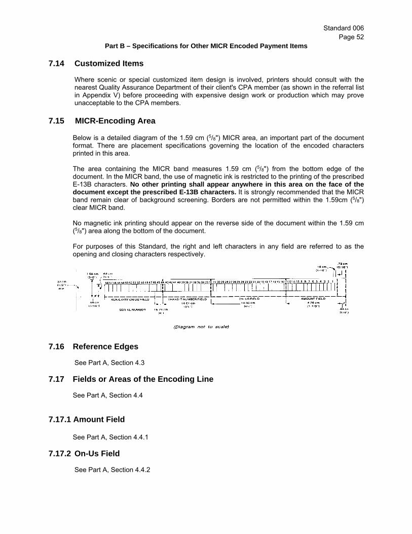
Standard 006 Page 52
Part B – Specifications for Other MICR Encoded Payment Items
7.14 Customized Items Where scenic or special customized item design is involved, printers should consult with the
nearest Quality Assurance Department of their client's CPA member (as shown in the referral list in Appendix V) before proceeding with expensive design work or production which may prove unacceptable to the CPA members.
7.15 MICR-Encoding Area
Below is a detailed diagram of the 1.59 cm (5/8") MICR area, an important part of the document format. There are placement specifications governing the location of the encoded characters printed in this area.
The area containing the MICR band measures 1.59 cm (5/8") from the bottom edge of the document. In the MICR band, the use of magnetic ink is restricted to the printing of the prescribed E-13B characters. No other printing shall appear anywhere in this area on the face of the document except the prescribed E-13B characters. It is strongly recommended that the MICR band remain clear of background screening. Borders are not permitted within the 1.59cm (5/8") clear MICR band.
No magnetic ink printing should appear on the reverse side of the document within the 1.59 cm (5/8") area along the bottom of the document.
For purposes of this Standard, the right and left characters in any field are referred to as the opening and closing characters respectively.
7.16 Reference Edges See Part A, Section 4.3 7.17 Fields or Areas of the Encoding Line See Part A, Section 4.4 7.17.1 Amount Field See Part A, Section 4.4.1 7.17.2 On-Us Field See Part A, Section 4.4.2

Standard 006 Page 53
Part B – Specifications for Other MICR Encoded Payment Items
7.17.3 Transaction Code Section Note : This section deals with transaction codes applicable to non-imageable MICR encoded
documents. Subject to the exceptions listed below, the Transaction Code Section may be blank or consist of a maximum of four (4) digits located between the closing symbol of the amount field and the opening symbol of the Account Number Section. Where applicable, spaces should be provided to accommodate combinations of pre-encoded and post-encoded information.
Exceptions:
Transaction code 96 shall be encoded on bill payment remittances; Transaction code 28 shall be encoded on Returned Item Carrier Envelopes, in
accordance with CPA Rule A4; Transaction code 45 shall be encoded on all U.S. Dollar Items2 except items having an
ABA routing number in the Transit Number Field, paper pre-authorized debits, and certain other items that may use a different transaction code in this field. Contact the financial institution’s Quality Assurance Division (See Appendix V) for details.
[Note: transaction code 05 is reserved for future use.]
Please see Appendix VII for a listing of all transaction codes for paper items reserved for CPA use. 7.17.4 Account Number Section See Part A, Section 4.4.2.2
7.17.5 Transit Number Field (a) MICR Encoded Documents
See Part A, Section 4.4.3 (b) MICR Encoding of Corporate Creditor Identification Numbers (CCINs) Corporate Creditor Identification Numbers shall be MICR encoded on bill payment Remittances only (in accordance with CPA Rule H6, Part II), and shall not be MICR encoded on cheques or other payment items. Please see diagram below for MICR line specifications for bill payment Remittances
2 The following Institutions are temporarily exempt from the requirement to encode transaction code 45 on U.S. Dollar items: Fédération des caisses Desjardins du Québec (currently using transaction code 11) and its members, the Credit Union Central of Nova Scotia (currently using transaction code 90) and its members, and the Central 1 Credit Union (currently using transaction codes 644 and 6404) and its members. These institutions will work towards migrating to the new transaction code on a best efforts basis as soon as possible.

Standard 006 Page 54
Part B – Specifications for Other MICR Encoded Payment Items
7.17.6 Auxiliary On-Us Field (also referred to as Serial Number Field)
Boundaries: 14.61 cm (53/4") from the right edge of the document continuing left to .32 cm (1/8") from the left edge of the document.
This variable length field is used for serial numbering when documents are of sufficient length. The maximum number of characters is fourteen (14) -- twelve (12) digits plus two (2) on-us symbols. This field must open with an on-us symbol. The field also closes with an on-us symbol, unless otherwise specified by the drawee financial institution. Blanks or dashes may replace one or more of these twelve digits. The closing symbol must be adjacent to the left-most digit. If this information is printed at the same time and using the same printing technique as the Transit Number Field, the blank normally required between the Auxiliary On-Us and Transit Number Fields may be omitted. Exception: The opening and closing on-us symbols may be omitted on MICR-encoded
documents when there is no data present in this field.
Customers must not use the Auxiliary On-Us Field without the prior consent of their financial institution Quality Assurance Department (see Appendix V).
Note: Customers should consult their financial institution Document Quality Assurance Department (refer Appendix V) for information regarding the maximum number of characters in any one field a MICR reader/sorter can classify.
7.18 Positioning See Part A, Section 4.5
7.18.1 Alignment See Part A, Section 4.5.1

Standard 006 Page 55
Part B – Specifications for Other MICR Encoded Payment Items
7.18.2 Character and Line Skew See Part A, Section 4.5.2 7.18.3 Spacing Requirements See Part A, Section 4.5.3
7.19 Cutting
See Part A, Section 3.7
7.20 Perforations See Part A, Section 3.6.1
7.21 Window Envelope Documents See Part A, Section 3.5 7.21.1 Window Envelope Limitations See Part A, Section 3.5.1. 7.22 Business Reply Envelopes The minimum size of documents established for the magnetic ink character recognition program
is 15.88 cm x 6.99 cm (6¼" x 23/4"), and the maximum size is 21.59 cm x 9.53 cm (81/2" x 3¾"). Since folded documents and creases through MICR characters increase the possibility of jams,
misreads and rejects in reader-sorters, it is recommended that undersized business reply envelopes not be used.

Standard 006 Appendix I
Technical Specifications for E13-B Characters in MICR Band
Standard 006, Appendix I Date of Publication: June 2006 Page 1 of 11
1.0 General Comments
In most cases, equipment common to most shops is adequate to print MICR characters. It is emphasized that an ink agitator is necessary. Presses should be in first-class condition.
In some cases, finer and more careful control of ink and water in the offset field is necessary in order to maintain a constant set of printing conditions.
In most cases magnetic ink can be used over the entire document provided the nearest impression to the 1.59 cm (5/8") MICR band does not extend into it.
Using magnetic ink for the entire document means only one run - a distinct cost advantage. With some documents this may be difficult to do, particularly where a heavy heading on the document requires a heavier film of ink than is desirable on the E-13B font.
When printing the whole document in MICR ink on continuous forms presses, extreme care must be exercised to avoid "tracking" into the 1.59 cm (5/8") MICR band.
1.1 Tolerance Limits
As the tolerance limit of one specification is approached, the more important it becomes not to approach the tolerance limit of any other specification. For instance, character dimensions, signal level, skew, debossment, voids, uneven ink coverage, etc., could individually be just within the standards. However, two or more of these conditions on the same document can make it unacceptable for electronic processing.
1.2 Laser-Printed Documents
The use of laser-printing technology to produce MICR-encoded documents has become
more prevalent for a variety of reasons. These include the ease with which appropriate equipment can be obtained and the requirement for certain clients to print their documents in-house.
A printer or business that implements a laser-printing solution should be aware of the
following common quality assurance problems attributable to this printing method, and the fact these problems may result in high reject rates: • inadequate permanence/fusion of MICR toner to paper which may cause:
o characters to flake off the paper and MICR ink to melt or smear as the document is read by a high-speed reader/sorter. This in turn may cause magnetic particles to transfer to other documents and lead to a build up of magnetic toner on the read film of processing equipment.
• E13-B character distortion.
It is important to note that every component in the printing solution must work well together in order to produce quality documents. Where strict attention is paid to quality

Standard 006 Appendix I
Technical Specifications for E13-B Characters in MICR Band
Standard 006, Appendix I Date of Publication: June 2006 Page 2 of 11
control, including the calibration of printing equipment and the use of quality toner, laser-printed cheques can be of very high quality.
It is strongly recommended that the following principles be implemented at the printing/user site in order to ensure the production of quality documents:
• a laser-printer should be designated for all MICR-encoded documents (Note: Every
printer is unique in terms of fusing properties and therefore some printers may not be well suited for MICR printing);
• clients should use supplies that are compatible and recommended by the equipment
manufacturer (Note: Each toner product is developed for a particular print engine); • printing equipment should be calibrated and maintained by qualified professionals on
a regular basis; • MICR-encoded document samples (such as cheques) should be forwarded to the
client's financial institution’s Quality Assurance department (refer to Appendix V) for testing on a regular basis, or every time a component in their end-to-end solution changes (alterations to any component in the printing solution may affect the MICR print quality); sample cheques (refer to sub-sections 1.4 and 1.4.1 of the Supplement for quantities) should be submitted in their final format (i.e., not just the MICR-line) (exact amount is at the discretion of each financial institution).
• a variety of testing devices to measure the quality of MICR printing are available in the
industry. The use of such devices is encouraged; and
• special training on current MICR standards may be required for in-house printing of laser-produced documents.
1.3 Letterpress Type
Most type houses across Canada carry the E-13B font. It should be pointed out that there
are two different fonts: one to be used for pulling reproduction proofs and another for letterpress use which is .003 cm (.001") smaller to allow for normal squeeze.
Electros and zinc cuts can be used, taking care that growth of the characters is normal. Type must always be clean and in good shape. It is important that all type be of equal
height because the maximum debossing allowable is .003 cm (.001"). It is important to inspect foundry type or other metal-faced type for flaws or other faults.
Type that is nicked or squashed should not be used. Matrices for intertype, linotype and Ludlow slugs must meet the specific dimensions within
a very narrow limit. Although linotype has been used successfully in some cases, it has been found that much greater care in the set-up and control of heat, mouth pieces, pump stroke, etc., must be taken, or too many irregularities, such as pits, will be present in the castings.
Rubber and plastic plates generally do not produce the required results.

Standard 006 Appendix I
Technical Specifications for E13-B Characters in MICR Band
Standard 006, Appendix I Date of Publication: June 2006 Page 3 of 11
Printers who contemplate casting their own material should use only clean, new metal. Old, deteriorated or dirty metal should be avoided.
Starting out with a type face that meets specifications will go a long way towards producing acceptable printed results. Type that is off its feet will cause excessive growth in one spot and a pinched, unfilled appearance in others, usually resulting in unacceptable printed characters.
1.4 Letterpress Impression
Strive for an impression setting that provides sufficient contact between type face and paper to produce a perfect image with a sharp outline.
Realizing that character growth will undoubtedly take place, characters for letterpress printing are very slightly smaller than the actual specified dimensions of the character as it should appear on paper.
Over-inking will result in excessive growth, fill-in and ragged edges, even if the impression setting is correct. Impression and ink film must be reconciled to each other in such a way that neither has to compensate for the other.
The aim should be to maintain ink film of even density, without voids or transparency, over the entire image area, and with the least possible amount of squeeze-out.
1.5 Offset Type
In the offset field, photoset type on film has proven most reliable in production work to
date. Most type houses across Canada provide this service. If type is used, it is of the utmost importance that top quality reproduction proofs be
pulled. New foundry type seems to provide the cleanest results, with the least growth and the least distortion.
If you pull your own reproduction proofs be sure to get the proper E-13B font for this
purpose. It is essential that the proof press be in top condition. Use a good high quality "repro"
proof paper or a high gloss finish book stock. Ink should be a good repro-black, using as little as is consistent with complete transfer
and kiss impression. In preparing the negative, use only good, reliable stable base film, a properly
compounded developer and sufficient agitation. Stripping and opaquing of negatives is highly important. All pin holes must be covered. No guide marks can appear within the 1.59 cm (5/8") band on which the MICR characters will appear. Final inspection of opaquing should be done with a magnifier over the opaque table to make sure that no pin holes appear.
With normal care there should be no difficulty in the preparation of either zinc or
aluminum plates. It is essential that good contact be maintained between metal plate and negative; otherwise halation could occur. Sufficient vacuum is essential to avoid image distortion or other changes.

Standard 006 Appendix I
Technical Specifications for E13-B Characters in MICR Band
Standard 006, Appendix I Date of Publication: June 2006 Page 4 of 11
Typewritten composition on paper offset masters is satisfactory for very short runs, but the printer moving into the MICR field might experience less difficulty working with either photoset film or foundry type.
Inspection of paper offset masters should be most rigid.
1.6 Offset Impression
As in letterpress, the aim is to lay down a magnetic ink film of constant thickness. Over-inking can cause image spread and distortion as well as difficulty in drying.
Special care should be given to ink distribution and the proper balance between ink and solutions. If not enough moisture is applied, the background of the plate may accept ink to make the work unacceptable.
Slur and double image can be caused by a loose blanket. A grey appearance may indicate that insufficient ink is being laid down. A deep, solid colour is desirable. Do not resort to over-inking to achieve what might appear to be a solid colour when other press adjustments can achieve this.
1.7 Magnetic Ink
1.7.1 General
Nearly all Canadian ink houses either make or handle magnetic ink. It is suggested that, where satisfactory results are obtained from a certain manufacturer of ink, you stay with that ink. Each ink handles a little differently and switching can lead to difficulties. This, of course, does not preclude any experimenting a printer might carry out in early stages, but once you are producing MICR characters acceptably, try to maintain every element of production the same for each run. Magnetic ink has certain peculiarities because it contains 50 to 60 percent iron oxide. It does not tend to follow the fountain roller. It has to be agitated by an ink fountain agitator or weighted with a suitable metal weight to push it towards the roller.
Magnetic ink takes longer to dry than normal inks and extra care has to be taken in early handling of the printed documents or running through the press a second time (refer to "Cutting" in Part A, sub-section 3.7 of Standard 006). Frequently, magnetic inks will not run consistently, particularly on offset machines. They must be checked carefully and at regular and frequent intervals to see that the image is still sharp and smooth.
To avoid problems, it is important that the ink manufacturer’s recommendations on storage, care and life expectancy be followed.
1.7.2 Ink Adjustments
Ink adjustments are not encouraged. Magnetic inks are carefully tailored and formulated to print "right out of the can" and generally need no adjustment at the press. Slight additions of drier, solvent, oil, etc., may be made but never more than 3% and preferably

Standard 006 Appendix I
Technical Specifications for E13-B Characters in MICR Band
Standard 006, Appendix I Date of Publication: June 2006 Page 5 of 11
less. This is most important since the "pigment" (actually iron oxide in this case) is present in just the right percentage and any excessive alteration of the ink will result in improper signal strength of the printed ink film. Because drying is sometimes a stubborn problem with certain stocks, some printers may be inclined to add drier indiscriminately. Too much drier affects press stability and causes non-uniformity of the magnetic ink film. Do not add toners to magnetic inks to increase jetness of blacks or strength of colours. To do so would upset the balance of the ink.
1.7.3 Driers
Extreme caution should be exercised when using any additives. Before adding such products to magnetic ink, be sure to consult the manufacturer of the ink for direction.
Since driers are not recommended, it is important to run as thin a film as possible, consistent with overall uniform coverage, which will produce sufficient signal strength.
1.7.4 Sprays
Sprays should not be used in MICR printing. Although this stops offsetting, it can be the cause of character edge bleeding that will make the characters unacceptable to the sorting machine.
1.7.5 Ink Film Thickness Control
The signal strength of characters printed with magnetic ink is directly proportional to the ink film thickness. Therefore, since the offset process lays down an ink film which is much thinner than that produced by letterpress, the magnetic or signal strength of offset inks must be considerably greater. This effect is accomplished by proper ink formulation.
1.7.6 MICR Ribbons
When ribbons are used for MICR printing, it is important that the manufacturer’s recommendations on storage, care and life expectancy be followed.
1.7.7 Sampling Plan for Inspection
Inspection of every document is costly; however, sampling inspection has proven quite satisfactory in practice. Once a press is set up to print an acceptable MICR line according to specifications, the printer must ensure that the balance of the run be within specifications regardless of any roll changes or mechanical adjustments that may be required.
1.7.8 Composition
Ink used for MICR-encoding must contain 50% to 60% iron oxide.

Standard 006 Appendix I
Technical Specifications for E13-B Characters in MICR Band
Standard 006, Appendix I Date of Publication: June 2006 Page 6 of 11
1.8 Printed Character: E-13B Common Language Standards
(Diagrams taken from ISO 1004-1995) Notes concerning figures 1.8.1 – 1.8.14 1. All radii are 0.165 mm (0.0065"), except for Stroke 0 (Zero). 2. All radii shall be blended with adjacent edges. 3. Tolerance: ± 0.038 mm (± 0.0015"). 4. Minimum width of horizontal bars is 0.279 mm (0.011"). This specification does
not apply to vertical bars. 5. Dimensions are in millimetres.
Fig.1.8.1– Stroke 0 (Zero) Fig 1.8.2– Stroke 1 (One)

Standard 006 Appendix I
Technical Specifications for E13-B Characters in MICR Band
Standard 006, Appendix I Date of Publication: June 2006 Page 7 of 11
Fig 1.8.3 Stroke 2 (Two) Fig 1.8.4 Stroke 3 (Three)
Fig 1.8.5– Stroke 4 (Four) Fig.1.8.6– Stroke 5 (Five)

Standard 006 Appendix I
Technical Specifications for E13-B Characters in MICR Band
Standard 006, Appendix I Date of Publication: June 2006 Page 8 of 11
Fig 1.8.7– Stroke 6 (Six) Fig.1.8.8– Stroke 7 (Seven)
Fig 1.8.9 – Stroke 8 (Eight) Fig 1.8.10 – Stroke 9 (Nine)

Standard 006 Appendix I
Technical Specifications for E13-B Characters in MICR Band
Standard 006, Appendix I Date of Publication: June 2006 Page 9 of 11
Fig.1.8.11– Stroke 10 (Symbol 1) Fig.1.8.12– Stroke 11 (Symbol 2) (Transit Number Symbol) (Amount Symbol)
Fig.1.8.13– Stroke 12 (Symbol 3) Fig.1.8.14– Stroke 13 (Symbol 4) (On-Us Symbol) (Dash Symbol)

Standard 006 Appendix I
Technical Specifications for E13-B Characters in MICR Band
Standard 006, Appendix I Date of Publication: June 2006 Page 10 of 11
1.9 Character Specifications
1.9.1 Dimensions
The minimum width of a horizontal bar in any character is .0279 mm (.011"). See sub- section 1.8 and figures 1.8.1 – 1.8.14.
1.9.2 Average Edge Tolerance
The contour of the character should reach no more than .038 mm (.0015") on either side beyond the average edge.
1.9.3 Edge Irregularity
The contour of 75% of the total edge of the character should not extend more than .0089cm (.0035") either way from the average edge.
1.9.4 Voids
In characters having bars less than two squares wide, voids must be contained within a .020 cm x .020 cm (.008" x .008") area.
In characters having bars two or more squares wide, voids must be contained within a .025 cm x .025 cm (.010" x .010") area.
Needle voids are permissible in any length providing they are no wider between average edges than .005 cm (.002").
The total area of voids in any vertical or horizontal bar of a character must not exceed
20% of the bar area.
1.9.5 Uniformity of Ink Film
The ink is to be distributed within the outlines of each character.
1.10 Signal Level
The allowable signal level range is 80% - 200% of the nominal signal level established for each character (see Appendix VI).
1.11 Extraneous Magnetic Ink within the 1.59 cm (5/8") Band
The following are the tolerances:
a) Spots up to .008 cm x .008 cm (.003" x .003") are acceptable in any number. (This measurement is the width of the channels between squares on the grid.)

Standard 006 Appendix I
Technical Specifications for E13-B Characters in MICR Band
Standard 006, Appendix I Date of Publication: June 2006 Page 11 of 11
b) Random spots up to .010 cm x .010 cm (.004" x .004") are permissible if they are limited to one per character space and not more than five in any one field.
c) On the back of the document within the 1.59 cm (5/8") band across the bottom,
individual spots up to .015 cm x 0.15 cm (.006" x .006") are permissible in any number.
1.12 Interchemical Thickness Gauge
An interchemical thickness gauge measures the thickness of the ink film on your rollers. The reader-sorter will accept printed characters varying from 80% to 200% of the nominal signal level of acceptance. If the volume of document printing does not warrant an investment in instruments to measure the electrical signals given off by an encoded line, it is recommended that samples of trial runs be submitted for testing to the nearest MICR Quality Assurance Department of the customer's CPA member (see Appendix V). When samples are submitted, ensure that a record is kept of the ink-roller data on each sample, which the interchemical thickness gauge can supply. If sample "A", for example, proves to be satisfactory, refer to the roller-coverage readings registered during the printing of sample "A" and thereafter maintain that roller coverage by the periodic use of the instrument. If you use another batch of ink at a later date, the above process should be repeated. It is important that the same ink and paper be used for both sample and production runs.
Interchemical thickness gauge

Standard 006 Appendix II
Quality Assurance
Standard 006, Appendix II Page 1 of 21 Date of Publication: June 2006
1.1 General Comments
This section of the Standard has been developed to assist printers and CPA members' personnel in monitoring and interpreting the standards. Each CPA Direct Clearer has developed a quality assurance program, and questions should be directed to the CPA member and department involved as indicated in Appendix V. You should not engage in MICR printing without the aid of a minimum of two instruments:
a) a printing and layout gauge; and b) a pocket comparator. In larger document printing operations, more extensive and more expensive equipment will be required.
1.2 Printing and Layout Gauges
1.2.1 General
A printing and layout gauge is necessary to check horizontal and vertical positioning, skew and other specifications. The gauge has a transparent screen that is placed over a proof/document to determine dimension, location, skew and other details as illustrated in Figure 1. In addition, the printing and layout gauge provides examples of MICR conventions -- minimum, nominal, and maximum -- which will help to judge the acceptability of the line you are printing. Note: In Canada the maximum size for cheques and other payment items is 21.59 cm (81/2") as shown on the printing and layout gauge in Figure 2.

Standard 006 Appendix II
Quality Assurance
Standard 006, Appendix II Page 2 of 21 Date of Publication: June 2006
Figure 1
Diagram courtesy of Clearwave Electronics Ltd. (not to scale)
1.2.2 Alignment
When printing MICR characters, the alignment of the bottom edge of any two adjacent numerical characters must not vary more than .018 cm (.007"). This tolerance is checked quickly and easily on the printing and layout gauge where a special checking line is provided for this purpose. Comparators can also be used to check this requirement. There are no limitations on alignment between fields, providing the upper and lower limits of the MICR fields measure .64 cm (1/4"), lie within the 1.59 cm (5/8") MICR band and the spacing between fields conforms to the standard spacing requirements (see section 1.2.4 of this document). When you purchase a photo-set line of MICR characters on film, you can usually depend on the supplier having met this specification. However, it takes only a moment to verify. If you use foundry type or monotype characters, care must be taken with lock-up to make certain that the bottom alignment comes within the required tolerance.

Standard 006 Appendix II
Quality Assurance
Standard 006, Appendix II Page 3 of 21 Date of Publication: June 2006
1.2.3 Character and Line Skew
Skew is the rotational deviation of a character from the vertical with reference to the bottom edge of the document. Each character must be judged on its own merit. Dirty matrices and bent encoder bar heads contribute to individual character skew. This, plus any line skew, is cumulative and represents total character skew. The maximum skew of any character or line cannot be more than 1½ degrees off vertical, either one way or the other, using the bottom edge of the cheque as a horizontal reference. This tolerance can be checked visually by using the printing and layout gauge, where test lines are provided for this purpose. A skew scale is also provided on the gauge for both line and character testing. Comparators can also be used to check these requirements.

Standard 006 Appendix II
Quality Assurance
Standard 006, Appendix II Page 4 of 21 Date of Publication: June 2006
1.2.4 Spacing Requirements
The space between MICR characters must conform to certain measurements. The distance between the right average edges of adjoining characters is .318 cm (.125"), plus or minus .025 cm (.010") in the Transit Number and Amount Fields. The plus or minus tolerance is the width of any one of the squares on the layout gauge grid. In the On-Us and Serial Number Fields, and between adjoining fields, the distance between right average edges can never be less than .292cm (.115"). When MICR characters are photo-set on film for offset reproduction, this requirement is usually met by the supplier. The shoulders of foundry type and monotype characters usually are cast to provide the proper distance. When using the printing and layout gauge, proceed as follows: a long-dashed line appears in space #43 (and #1). When the symbol, at nominal line width, is placed between this line and the right-hand solid vertical line of space #43, all characters in this field should have their right-hand edge touching the vertical space-lines. When a character is out of contact, or under a line, the gauge should be shifted to bring the character into space #43 where the tolerance can be checked. Comparators can also be used to check this requirement one character at a time, where one character may look doubtful under your examination with the layout gauge.

Standard 006 Appendix II
Quality Assurance
Standard 006, Appendix II Page 5 of 21 Date of Publication: June 2006
1.3 Comparators
1.3.1 General
The pocket comparator enlarges the print image 12 times and enables you to see and verify the position and width of horizontal and vertical bars, overall dimensions and general quality.
A grid designed to give a visual check on the image is etched on the window surface of the pocket comparator. More powerful table model comparators enlarge many times more than pocket comparators and provide a greater degree of accuracy. Table model comparators use a layout chart with a grid as the centre of its format.

Standard 006 Appendix II
Quality Assurance
Standard 006, Appendix II Page 6 of 21 Date of Publication: June 2006
1.3.2 The Grid - A Key to Quality Assurance
The grid which appears on the lens through which you view the magnified image is a pattern of
etched squares against which the darker image of the character under examination shows up sharply.
The printer who is being asked to print characters within these limits must have some visual
means of determining whether or not the characters printed are too thick, too narrow, too heavy, too light, or just right. This can be done with a comparator which enlarges the printed impression of the character to a point where minute variations are plainly seen and provides a grid or pattern against which to measure variations not in millimetres (decimal centimetres, thousandths of an inch) but simply by comparison to plainly discernible areas. The following is a simple explanation of the principle of the grid pattern which printers will use in MICR work: Suppose you were given a printing assignment to produce and print a line of 8 point type exactly 2.54 cm (1") long and you were told that you might have .020 cm (.008") leeway. How could you be sure that your line did not measure the prescribed 2.54 cm (1") plus, say, .025 cm (.010")?
To measure such a line would require exact equipment and highly trained and experienced technicians. But, if you were given a pattern of that distance and some means to enlarge the 2.54 cm (1") line to a point where millimetres (decimal centimetres, thousandths of an inch) were easy to see, you would have no difficulty in printing that line to meet the required specifications.
While the pattern itself would conform exactly in millimetres (decimal centimetres, thousandths of an inch) to the specifications, you would not be asked to measure that .020 cm (.008") tolerance. All you would have to do would be to keep your 2.54 cm (1") line within two marks, say, on a transparent piece of plastic.
Put that extremely accurate piece of plastic against the printed impression of your 2.54 cm (1") line; enlarge the whole thing up to a point where you can see if your impression touches, nearly touches or goes over the line and you have really measured the line in millimetres (decimal centimetres, thousandths of an inch)… not by measuring in the sense of computing the distance, but simply by comparing the line with a guide which you know represents the exact distance required. Under such circumstances you do not need to know how many millimetres (decimal centimetres, thousandths of an inch) you can go this way or that; millimetres (decimal centimetres, thousandths of an inch) need not come into the picture. The pattern has taken care of the strict requirements and all you have to do is match the pattern. If your printed image falls within the boundaries of that pattern, you are automatically complying with millimetre (decimal centimetres, thousandths of an inch) tolerances.
In principle and in practice, this is exactly what you do when you check a MICR character with a viewer or comparator. The grid supplies the pattern and when you view the printed character through it, the image is enlarged up to a point where you can see whether it is too thick or too thin because the grid provides the reference marks needed to do this.
The tolerance data which follows, is expressed in millimetres (decimal centimetres, thousandths of an inch) as well as in terms of comparison with the grid pattern areas. These you can see on your comparator.

Appendix II
Quality Assurance
Standard 006, Appendix II Page 7 of 21 Date of Publication: June 2006
The grid, as seen in the above illustration and following pages, is a pattern of identical squares separated by channels of uniform width. The characters used in MICR printing are closely related to the size of the squares on the grid. The various strokes which make up MICR characters are one, two, three or four squares wide. The ideal printed character will fill the respective number of squares and will bisect the channels on either side of the squares. When the magnified image of the character is viewed against the grid, it is easy to see if it meets the required standards. The digit "8" in figure 1.4.3 is in an "Acceptable" form. All of its edges lie between the squares within the channels. The digit "8" in figure 1.4.4 is at the "Upper limit of tolerance". The edges extend over the channels between the squares and are touching the adjacent squares. The digit "8" in figure 1.4.5 is in an "Unacceptable" form. Its edges do not cover the minimum designated area.
Appendix II
Quality Assurance
Standard 006, Appendix II Page 8 of 21 Date of Publication: June 2006
A printed MICR character is within tolerance if its right, left, top and bottom average edges lie within the channels between squares when the character is viewed in isolation, under the grid (see figure 1.4.1). Thus, the use of the grid enables one to see if the vertical and horizontal bars of a character are positioned properly in relation to one another and if they are within tolerance. So that you may relate the size of the squares and the channels between them to the millimetres (decimal centimetres, thousandths of an inch) usually used in stating tolerances, and get the feel for these tolerances on the viewing screen of the grid, these sizes are as follows:
a) each square on the grid is .025 cm x .025 cm (.010" x .010"); and b) the channel between the squares is .008 cm (.003") wide
Here, then, is where you can reconcile the tolerances which the electronic sorting machine demands. There are no millimetre (one-thousandth) graduations on the grid pattern, but with the knowledge that each square is .025 cm (.010") wide, with intervening channels .008 cm (.003") wide, and also with examples of MICR character printing to illustrate both permissible and unacceptable variances, you should have no difficulty.
1.4 Character Dimensions
The minimum width of the horizontal single stroke bars in any character, (e.g. the uppermost bar of the digit "8") is to be .028 cm (.011"). The minimum width of vertical bars is governed entirely by dimensions locating each edge. Subject to these dimensions being correctly at tolerance limit (see figures 1.4.1 – 1.4.5 for diagrams of "8's"), the minimum width of these vertical bars may be as low as .025 cm (.010"). For use of the grid in testing character dimensions refer to figure 1.4.1.

Appendix II
Quality Assurance
Standard 006, Appendix II Page 9 of 21 Date of Publication: June 2006
1.4.1 Illustration of E-13B Font Characters as They Appear on the Grid

Appendix II
Quality Assurance
Standard 006, Appendix II Page 10 of 21 Date of Publication: June 2006

Appendix II
Quality Assurance
Standard 006, Appendix II Page 11 of 21 Date of Publication: June 2006
1.4.2 Example of Grid Detail
CHARACTER EDGE IRREGULARITY
CHARACTER DIMENSION TOLERANCE
.006cm (.002”)
.025cm (.010”)
.033cm (.013”)
.008cm (.003”)

Appendix II
Quality Assurance
Standard 006, Appendix II Page 12 of 21 Date of Publication: June 2006
1.4.3 Acceptable Character Dimensions
Reproduced through the courtesy of Canadian General Electric Company Limited and Honeywell Systems.

Appendix II
Quality Assurance
Standard 006, Appendix II Page 13 of 21 Date of Publication: June 2006
1.4.4 Upper Limit of Character Dimension Tolerance
Reproduced through the courtesy of Canadian General Electric Company Limited and Honeywell Systems.

Appendix II
Quality Assurance
Standard 006, Appendix II Page 14 of 21 Date of Publication: June 2006
1.4.5 Unacceptable Character Dimensions
Reproduced through the courtesy of Canadian General Electric Company Limited and Honeywell Systems.

Appendix II
Quality Assurance
Standard 006, Appendix II Page 15 of 21 Date of Publication: June 2006
1.5 Average Edge Tolerance
When magnified, it can be seen that the typical edge of a printed character is not a straight line. The average edge can be considered as an imaginary line dividing the irregularities as equally as possible. In viewing MICR characters, this becomes a matter of judgment. When you size this average edge on the comparator, the character dimension should reach no more than .0038 cm (.0015") on either side of the average edge dimension. In other words, the average edge must stay within the channels between the squares on the grid. Bear in mind that the minimum dimension of single width horizontal lines is limited to .028 cm (.011") and vertical lines to .025 cm (.010").
1.6 Edge Irregularity
Peaks and valleys about the average edge are permitted to extend to plus or minus .0089 cm (.0035") from the dimension locating the edge. However, when these occur, the summation of the edge present in the .0038 cm to .0089 cm (.0015" to .0035") zone shall not exceed 25 percent of the total edge.
Acceptable Excellent
Unacceptable. Over 25% irregularity. Unacceptable. Peaks and valleys beyond tolerance.

Appendix II
Quality Assurance
Standard 006, Appendix II Page 16 of 21 Date of Publication: June 2006
1.6.1 Edge Irregularity Tolerance
1.7 Voids
Voids are the absence of ink within the specific outline of the printed character. If any part of a void opens into the edge of the character, it is considered an edge irregularity. When enlarged, practically every printed surface presents voids. You can judge these voids in MICR characters under the comparator by relating their size to the .025 cm (.010") squares on the grid. In those bars of a character less than two squares wide -- such as in the upper part of the digit "8" -- voids must be contained within a .020 cm x .020 cm (.008" x .008") area.

Appendix II
Quality Assurance
Standard 006, Appendix II Page 17 of 21 Date of Publication: June 2006
In those bars of a character two or more squares wide -- such as in the lower part of the digit "8" -- voids must be contained within a .025 cm x .025 cm (.010" x .010") area. Simply stated, voids in these bars must fall within the area equal to that of any square on the grid. Needle voids are long, slim areas where no ink appears. These are permissible in any length providing they are no wider between average edges than .005 cm (.002"), slightly less than the width of the channels between the squares on the grid. Needle voids often occur when long paper fibres lie close to the surface. The total area of voids in any vertical or horizontal bar of a character must not exceed 20% of the bar area. Determining this must rest with your judgement.
1.8 Extraneous Magnetic Ink within the 1.59 cm (5/8") MICR Band
Every printer knows that bits of ink, barely discernible to the naked eye, result from
unavoidable splatter, smear, etc. Under a viewer these will show up. Within the 1.59 cm (5/8") MICR band the tolerances are as follows:
Note: These are illustrations only and characters and extraneous ink are exaggerated.
1) Spots up to .008 cm x .008 cm (.003" x .003") are acceptable in any number. This measurement is the width of the channels between squares on the grid.
An acceptable needle void. Unacceptable needle void.
An acceptable void. Unacceptable void. Voids exceed 20% of the bar area.
Appendix II
Quality Assurance
Standard 006, Appendix II Page 18 of 21 Date of Publication: June 2006
2) Extraneous ink spots exceeding .010 cm x .010 cm (.004" x .004") are unacceptable.
3) Random spots up to .010 cm x .010 cm (.004" x .004") are permissible if they are limited to one per character space and not more than five in any one field.
4) On the back of the item, and with the 1.59 cm (5/8") band at the bottom, individual spots up to .015 cm x .015 cm (.006" x .006") are permissible in any number.
Illustrations of Extraneous Magnetic Ink
Spots up to .008 cm X .008 cm (.003" X .005") are acceptable in any number. This measurement is the width of the channels between squares on the grid.
Acceptable extraneous ink dots on front of an item – one per character space and not more than five in any one field - .010 cm X .010 cm (.004" X .004")
Unacceptable extraneous ink dots on front of an item – larger than .010 cm X .010 cm (.004" X .004").
Spots too large – more than .010cm x .010cm (.004” x .004”)
Too many .010cm x .010cm (.004”) spots
Acceptable spots - .008cm x .008cm (.003” x .003”) or less.

Appendix II
Quality Assurance
Standard 006, Appendix II Page 19 of 21 Date of Publication: June 2006
Acceptable extraneous ink dots on the back of the item, on the reverse of the 1.59cm (⅝") MICR band. Individual spots up to .015 cm X .015 cm (.006" X .006") are permissible in any number.
Unacceptable extraneous ink dots on the back of the item on the reverse of the 1.59 cm (⅝") MICR band – larger than .015 cm X .015 cm (.006" X .006").
1.9 Uniformity of Ink Film
The ink is to be distributed uniformly within the outlines of each character. Conditions
should be avoided that result in excessive squeeze-out, halo and other uneven deposits. Conditions should also be avoided which would result in chipping or smearing of ink on the paper after the drying period.
Acceptable Uneven ink coverage
Ghost Image Excessive squeeze-out or halo

Appendix II
Quality Assurance
Standard 006, Appendix II Page 20 of 21 Date of Publication: June 2006
1.10 Debossment/Embossment
Debossment is the depressing of the paper surface caused by excessive printing
pressure. The tolerance specified is not more than .003 cm (.001"). The only equipment which can provide a precise measurement of debossment is a light
section microscope or a debossment microscope. Micrometers will provide a guideline in measuring debossment. However, extreme caution must be exercised in interpreting readings from these production tools. Readings taken with micrometers usually show a lesser degree of debossment than is actual.
Every effort should be made to minimize debossment in order to ensure that it does not
exceed the .003 cm (.001") tolerance. Judging debossment is the skill of the experienced printer. When general printing quality
of MICR has been established there should be no difficulty in controlling debossment to keep within limits. However, special equipment is available for checking depth of impression.
Embossment is a physical build-up of dry ink on paper causing the characters to sit
above the surrounding paper surface. For most dry ink images, an embossment value of 0.0015cm (0.0006") or less should result in acceptable reader/sorter wear.
1.11 Allowable Signal Level Range (80% to 200% of the Nominal Signal Level
Established for Each Character) The document printer whose volume may warrant an investment in a magnetic ink tester,
may, of course, check the signal strength of MICR printing in his shop. For the smaller printer, whose volume may not warrant the purchase, there is no means of testing the signal strength of MICR characters except to have this done through his CPA member's nearest Quality Assurance Department (see Appendix V).
While signal levels may vary from 80% to 200% of the nominal signal level established
for each character, in actual practice the tolerance is not as broad as these figures might indicate. Running at the lower level may give problems with voids; running at the upper level may create problems with drying and squeeze-out.
1.12 Document Testing
1.12.1 Initial Setup
Your CPA member will co-operate fully in this matter. The following procedure is
recommended: Run off four or five batches of documents, ensuring that all specifications in matters of
positioning, measurement tolerances, impression and imageability are met. For the first batch, keep your ink coverage quite light.
You will finish with four or five sample batches of documents, each printed with different
roller coverage.

Appendix II
Quality Assurance
Standard 006, Appendix II Page 21 of 21 Date of Publication: June 2006
Submit the different batches, each plainly identified, to your CPA member's nearest Quality Assurance Department (see Appendix V) and they will be tested and returned with a report indicating which are acceptable. The procedures for submitting documents, the sample plan, and the conditions to be tested are detailed in Section 1 of the Supplement to Standard 006.
Do not forget to use the same manufacturer's ink and the paper you used when you ran
the samples. This is important. So is the use of an ink agitator (see Appendix 1, Section 1.0). If you use another batch of ink at a later date, the above process should be repeated.
Note: The ideal levels average 110% to 125% of the nominal signal level established for each character.
1.12.2 Ongoing Quality Assurance Testing
Samples from both the start and finish of each production run should be submitted for
acceptance to the Quality Assurance Department of your customer's CPA member. 1.12.3 Evaluation Report The Quality Assurance Department of each CPA member will provide comments on their
evaluation in an Evaluation Report based on “Conditions to be tested on Imageable MICR Documents Prior to Processing” (see Section 1 of the Supplement).

Standard 006 Appendix III
Standard 006, Appendix III Page 1 of 1 Date of Publication: June 2006
MICR CODELINE SPECIFICATIONS CHARACTER ARRANGEMENT IN E-13B TYPE
To aid in maintaining MICR standards, Direct Clearers provide a testing and general information service. Please contact the financial institution’s Quality Assurance Division for further
details (See Appendix V). Please refer to CPA Standard 006, Part A – “Specifications
For Imageable MICR-Encoded Payment Items" for printing details.

Standard 006 Appendix IV
Standard 006, Appendix IV Page 1 of 2 Date of Publication: June 2006
MICR FIELD PLACEMENT AND CONTENT
Before each printing or reprinting of documents, printers must obtain a new specifications sheet from their customer's CPA member. The following layouts are strictly a guideline:

Standard 006 Appendix IV
Standard 006, Appendix IV Page 2 of 2 Date of Publication: June 2006
4.5.

Standard 006 Appendix V
QUALITY ASSURANCE DEPARTMENT LIST
Page 1 of 3
While every attempt has been made to provide all possible information regarding the printing of imageable MICR-encoded documents, situations may arise for which you would require clarification or additional information. The following list is provided for your assistance in obtaining the desired information. ALBERTA TREASURY BRANCHES
CPA/CBA Coordinator Central Services 4th Floor, 919 – 11th Avenue S.W. Calgary, Alberta T2R 1P3
1-877-212-8585
BANK OF CANADA
Banking Services 234 Wellington Street Ottawa, Ontario K1A 0G9
(613) 782-8414
BANK OF MONTREAL
Symcor Inc. Quality Assurance Department 8 Prince Andrew Place Toronto, Ontario M3C 2H4
(416) 673-2834 or (416) 673-2836
BANK OF NOVA SCOTIA
Symcor Inc Quality Assurance Department 8 Prince Andrew Place Toronto, Ontario M3C 2H4
(416) 673-2834 or (416) 673-2836
FÉDÉRATION DES CAISSES DESJARDINS DU QUÉBEC
Fédération des caisses Desjardins du Québec Quality Assurance 1, Complexe Desjardins C.P. 7 – Succursale Desjardins Montréal (Québec) H5B 1B2
(514) 281-7000 ext 8710 or (888) 866-7000 ext. 870
La confédération des caisses populaires Desjardins de Montréal et de l’ouest-du-Québec 1, Complexe Desjardins C.P. 35 – Succursale Desjardins Montréal (Québec) H5B 1E7 ATTN: Le centre Desjardins de compensation
(514) 281-8688
CANADIAN IMPERIAL BANK OF COMMERCE
Quality Assurance Officer INTRIA Items Inc. 155 Britannia Rd E Mississauga, Ontario L4Z 4B7
(905) 502-4212 or (888) 872-5888

Standard 006 Appendix V
QUALITY ASSURANCE DEPARTMENT LIST
Page 2 of 3
CREDIT UNION CENTRAL OF ALBERTA LIMITED
Quality Assurance Analyst 350 N, 8500 MacLeod Trail S.E. Calgary, Alberta T2H 2N1
(403) 259-7505
Team Leader Payment Support 350 N, 8500 MacLeod Trail S.E. Calgary, Alberta T2H 2N1
(403) 259-7504
CREDIT UNION CENTRAL OF BRITISH COLUMBIA
Supervisor, Item Processing Payment Systems Department 1441 Creekside Drive Vancouver, British Columbia V6J 4S7
(604) 737-5035
CREDIT UNION CENTRAL OF MANITOBA
Tracing Department 215 Garry Street Box 9900 Winnipeg, Manitoba R3C 3EZ
(204) 985-4700
CREDIT UNION CENTRAL OF ONTARIO LIMITED
Symcor Inc Quality Assurance Department 8 Prince Andrew Place Toronto, Ontario M3C 2H4
(416) 673-2834 or (416) 673-2836
CREDIT UNION CENTRAL OF SASKATCHEWAN
Quality Assurance Analyst 350 N, 8500 MacLeod Trail S.E. Calgary, Alberta T2H 2N1
(403) 259-7505
Team Leader Payment Support 350 N, 8500 MacLeod Trail S.E. Calgary, Alberta T2H 2N1
(403) 259-7504
HSBC BANK CANADA
Symcor Inc Quality Assurance Department 8 Prince Andrew Place Toronto, Ontario M3C 2H4
(416) 673-2834 or (416) 673-2836
Standard 006 Appendix V
QUALITY ASSURANCE DEPARTMENT LIST
Page 3 of 3
LAURENTIAN BANK OF CANADA
Laurentian Bank of Canada Processing & Operations 555 Chabanel Street West Suite 500 Montreal, Quebec H2N 2H8
(514) 284-4500 ext 8868
NATIONAL BANK OF CANADA
Quality Assurance Department Cash and Clearing Management Group Transit 006 – 1567 – 1 600, de la Gauchetière West Level C Montreal, Quebec H3B 4L7
(514) 394-6393 or (800) 361-8688 ext. 6393
ROYAL BANK OF CANADA
Symcor Inc Quality Assurance Department 8 Prince Andrew Place Toronto, Ontario M3C-2H4
(416) 673-2834 or (416) 673-2836
THE TORONTO-DOMINION BANK
Symcor Inc Quality Assurance Department 8 Prince Andrew Place Toronto, Ontario M3C 2H4
(416) 673-2834 or (416) 673-2836

Standard 006 Appendix VI
Standard 006, Appendix VI Page 1 of 2 Date of Publication : June 2006
Allowable Signal Level Range Exhibits CPA Signal Level Standard
The current CPA Signal Level Standard is defined as a measurement of 80% to 200% of the nominal signal level. The Signal Level Standard and acceptable variations are further defined and explained in the following exhibits.
* Counting vertical edges right to left on the printed character: counting peaks left to right on the
displayed waveforms and including positive and negative peaks. These impulses are measured in millivolts.
132

Standard 006 Appendix VI
Standard 006, Appendix VI Page 2 of 2 Date of Publication : June 2006
Waveform as it Appears on Oscilloscope at Minimum Signal Level for This Symbol
Waveform Peaks for Signal Level Measurement

Standard 006 Appendix VII
Standard 006, Appendix VII Date of Publication: January 2008
List of All Paper Transaction Codes Reserved for CPA Use
Transaction Code Payment Type Transaction Code 28 Transaction code 28 shall be encoded on
Returned Item Carrier Envelopes, in accordance with CPA Rule A4.
Transaction Code 33 Transaction code 33 shall be encoded on Business Pre-Authorized Debits (PADs), in accordance with CPA Rule H1.
Transaction Code 44 Transaction code 44 shall be encoded on Cash Management PADs in accordance with CPA Rule H1.
Transaction code 45 Transaction code "45"1 shall be encoded on all U.S. Dollar Items drawn on a U.S. Dollar account held with a member or drawn on the Canada Post Corporation, with the exception of paper Pre-Authorized Debits, Items encoded with an ABA Routing Number, and certain other U.S. Dollar Items on which a CPA Member may encode a different transaction code.
Transaction Code 81 Transaction code 81 may be required on Gift Certificates and Store Coupons in accordance with CPA Rule H2.
Transaction Code 83 Transaction code 83 shall be encoded on Funds Transfer PADs where no recourse is provided in accordance with CPA Rule H1.
Transaction Code 96 Transaction code 96 shall be encoded on bill payment remittances.
[Note: transaction code 05 is reserved for future use.]
1 The following Institutions are temporarily exempt from the requirement to encode transaction code 45 on U.S. Dollar items: La Caisse centrale Desjardins du Québec (currently using transaction code 11) and its members, the Credit Union Central of Nova Scotia (currently using transaction code 90) and its members, and the Credit Union Central of Canada (currently using transaction codes 644 and 6404) and its members. These institutions will work towards migrating to the new transaction code on a best efforts basis as soon as possible.
Date of Publication: January 2009
CANADIAN PAYMENTS ASSOCIATION
STANDARD PROCEDURES
FOR THE
EVALUATION OF IMAGEABLE MICR-ENCODED
DOCUMENTS
A Supplement to Standard 006
Part A: Specifications for Imageable MICR-Encoded P ayment Items Part B: Specifications for Other MICR-Encoded Payme nt Items
Supplement to Standard 006
Date of Publication: January 2009
TABLE OF CONTENTS
Page 1. TESTING OF IMAGEABLE MICR DOCUMENTS PRIOR TO PRO CESSING THROUGH THE CANADIAN CLEARING AND SETTLEMENT SYSTEM
1.1 Introduction ............................................................................................................................ S1 1.2 Standard Procedures for Obtaining Imageable MICR Documents for Testing ...................... S2
1.2.1 Category “A” ......................................................................................................... S2 1.2.2 Category “B” ........................................................................................................ S3 1.2.3 Category “C” ........................................................................................................ S4
1.3 Background Screening ........................................................................................................... S5 1.4 Sampling ................................................................................................................................. S6
1.4.1 Sampling Plan for Inspection of Imageable MICR-Encoded Documents ............ S7 1.5 Conditions to be Tested on MICR Documents prior to Processing ....................................... S8
2. TESTING OF IMAGEABLE MICR DOCUMENTS AFTER PROCES SING THROUGH THE CANADIAN CLEARING AND SETTLEMENT SYSTEM
2.1 Introduction ........................................................................................................................... S11 2.2 Schema for the Inspection of Imageable MICR Document Rejects after Processing through the Canadian Clearing and Settlement System ...................................................... S11 2.3 Procedures for Obtaining and Evaluating Imageable MICR Document Rejects ................. S12 2.4 Conditions to be Tested on Physical MICR Document Rejects and Verification of Source of Error/Defect ......................................................................................................... S13 2.5 Conditions to be Tested on Images of MICR Document Rejects and Verification of
Document Rejects and Verification of Source of Error/Defect ............................................. S18 2.6 Remedial Action Required and Report Procedures ............................................................. S19

Supplement to Standard 006
Date of Publication: January 2009
FOREWORD The "Canadian Payments Association Standard Procedures for the Evaluation of Imageable MICR- Encoded Documents" is presented as a Supplement to Standard 006. The standards and specifications described in this Supplement are intended to improve and formalize quality assurance and reporting procedures for all MICR-encoded documents which are intended for imaging and processing through CPA member MICR computerized sorting equipment. This CPA publication is the standard recognized by the financial institution industry for the evaluation of Imageable MICR-encoded documents within Canada. For those parties interested in obtaining more information pertaining to the design or production of MICR-encoded documents, they are referred to Standard 006. We gratefully extend our thanks to all those who assisted in the preparation of this publication and, in particular, acknowledge the following organizations to which we had recourse for reference:
National Institute of Standards and Technology (U.S.A.) Canadian General Standards Board National Research Council (Canada)

Supplement to Standard 006 S1
Date of Publication: January 2009
1. TESTING OF IMAGEABLE MICR DOCUMENTS PRIOR TO PRO CESSING THROUGH THE CANADIAN CLEARING AND SETTLEMENT SYSTEM
1.1 Introduction
This standard is intended to provide a common test vehicle among all CPA members to ensure a consistently high quality level of imageable MICR-encoded documents. The specifications and procedures described in this section apply to the testing and evaluation of MICR-encoded documents prior to processing through the Canadian clearing and settlement system.
Because of the various sources and types of MICR-encoded documents, this section has been divided into three categories as follows:
Category "A" - Imageable MICR documents that are printed by CPA member-contracted
printing houses (e.g. current account cheques and personal cheques) whether paid for by the CPA member or the customer, for processing through the Canadian clearing and settlement system.
Category "B" - Custom imageable MICR documents that are printed by a
customer-contracted printing house for processing through the Canadian clearing and settlement system.
Category “C” - Imageable MICR documents that are printed “in-house” by clients (e.g. through use of personal software/printers).
This sampling plan was developed to determine the number of random MICR-encoded document samples to be taken from various sizes of production runs. Corresponding acceptance and rejection levels for each approved sample size taken from a production run were also established to effect a maximum reject rate of 1% as per Standard 006.
The conditions to be tested on imageable MICR-encoded documents (page S8-S11) represent a predetermined mandatory list of document conditions to be tested in the order of testing sequence.

Supplement to Standard 006 S2
Date of Publication: January 2009
1.2 Standard Procedures for Obtaining Imageable MIC R Documents for Testing 1.2.1 Category "A"
Imageable MICR documents that are printed by CPA member-contracted printing houses (e.g., current account cheques and personal cheques) whether paid for by the CPA member or the customer, for processing through the Canadian clearing and settlement system.
The following standard procedures will apply for obtaining, testing and approving Category "A" Imageable MICR-encoded document samples prior to their processing through the Canadian clearing and settlement system.
RESPONSIBILITY PROCEDURE CPA Member Branch Order new and/or additional cheques for customers as well as its own
internal MICR documents according to member’s internal procedures.
Ensure that all order forms are completed in as per standards for each CPA member in conformance with Standard 006.
Ensure, upon receipt of the CPA member's "Image and MICR Quality Assurance Evaluation Report", that unacceptable imageable MICR documents identified in the report are destroyed at the time of replacement.
Printer Ensure all order forms are completed as per standards for each CPA member and in conformance with Standard 006.
Ensure that the printing of imageable MICR documents adheres to Standard 006, Part A.
Provide sample MICR Documents from each individual customer and/or bulk order in accordance with approved sampling plans (pages S7-S8). Forward these samples to the CPA member's Quality Assurance Department prior to delivery of the order.
Note: It is recommended that orders not be shipped until approved by
the CPA member's Quality Assurance Department. Reprint any unacceptable order as reported on the CPA member's
"Image and MICR Quality Assurance Evaluation Report". Repeat above sampling procedures for these unacceptable orders.
Forward, upon approval, replacement imageable MICR documents to the member branch, identifying the order as a reprint.
Note: Destroy the unacceptable order if that order is being held. Ensure the receipt of sample imageable MICR documents from each
order (see pages S7-S8). Quality Assurance Schedule regular MICR document evaluation tests for samples (see S8- Department S11).

Supplement to Standard 006 S3
Date of Publication: January 2009
Note: It is suggested that tests be scheduled in time to provide results to the printer prior to shipment of the order.
Prepare an "Image and MICR Quality Assurance Evaluation Report" for all documents not meeting Standard 006, Part A and forward copies of this report to the member branch and/or printer.
Ensure that unacceptable documents reported above are reprinted and new samples are received and evaluated in accordance with the preceding procedures.
Ensure that all unacceptable imageable MICR documents are destroyed. 1.2.2 Category "B"
Custom imageable MICR documents that are printed by a customer-contracted printing house for processing through the Canadian clearing and settlement system. The following standard procedures will apply for obtaining, testing and approving Category "B" Imageable MICR document samples prior to their processing through the Canadian clearing and settlement system.
The following procedures also apply to the following categories of MICR documents in situations where agreements can be negotiated by CPA members:
� Traveller's cheques; � Government of Canada cheques; � Paper-based Pre-authorized debits; and � Foreign bank cheques.
Note: Where agreement cannot be negotiated, it is recommended that "CPA Standard Procedures for the Evaluation of Imageable MICR-Encoded Documents" be made available to the above customers for the purpose of controlling quality within their own Quality Assurance Department.
RESPONSIBILITY PROCEDURE CPA Member Branch Receive notification from customers or printers for Imageable MICR
document printing.
Obtain an agreement with the customer to ensure that sample Imageable MICR documents are supplied in accordance with approved sampling plans (pages S7-S8) to the CPA member's Quality Assurance Department. Samples must be evaluated and approved prior to acceptance of the order by the customer.
Note: The "Specifications Sheet for MICR and Imageable Documents"
could serve as the vehicle for this agreement. Complete a "Specifications Sheet for MICR and Imageable Documents" which conforms to Standard 006, entering the required information as per individual member standards.

Supplement to Standard 006 S4
Date of Publication: January 2009
Note: Individual members may add supplementary instructions to the "Specifications Sheet for MICR and Imageable Documents" to satisfy internal procedures. Distribute copies of "Specifications Sheet for MICR and Imageable Documents" as follows:
� 2 copies to customer (1 copy for printer); � 1 copy to member's Quality Assurance Department; and � 1 copy to be retained at the member branch.
Ensure, upon receipt of the member's "Quality Assurance Evaluation Report", that unacceptable imageable MICR documents identified in the report are destroyed at the time of replacement.
Customer Inform member branch of intention to print custom Imageable MICR documents through a customer-contracted printer. Enter into an agreement with the member branch to provide sample documents in accordance with approved sampling plans (pages S7-S8) to the member's Quality Assurance Department for evaluation. Approval of the samples must be received prior to acceptance of the order. Obtain two completed and authorized copies of the "Specifications Sheet for MICR and Imageable Documents" from the member branch. Provide printer with a copy of the "MICR Specifications Sheet". Approve MICR proof document received from printer. Ensure document samples are forwarded, in accordance with approved sampling plans, to the member's Quality Assurance Department for testing. Ensure sample documents are approved by the member's Quality Assurance Department prior to customer acceptance of the order. Repeat the above instructions for subsequent or reprinted orders. Ensure that all unacceptable documents are destroyed. 1.2.3 Category “C”
Custom Imageable MICR documents that are printed “in-house” by clients (e.g. personal software/printers) for processing through the Canadian clearing and settlement system. The following standard procedures will apply for obtaining, testing and approving Category "C" Imageable MICR document samples prior to their processing through the Canadian clearing and settlement system.
RESPONSIBILITY PROCEDURE CPA Member Branch Receive notification from customers or printers of Imageable MICR
document printing.

Supplement to Standard 006 S5
Date of Publication: January 2009
Obtain an agreement between the member branch and customer to ensure that sample Imageable MICR documents are supplied in accordance with approved sampling plans (pages S7-S8) to the CPA member's Quality Assurance Department. Samples must be evaluated and approved prior to acceptance of the order by the customer.
Note: The "Specifications Sheet for MICR and Imageable Documents" could serve as the vehicle for this agreement.
Complete a "Specifications Sheet for MICR and Imageable Documents" which conforms to Standard 006, Part A entering the required information as per individual member standards.
Note: Individual members may add supplementary instructions to the "Specifications Sheet for MICR and Imageable Documents" to satisfy internal procedures. Distribute copies of "Specifications Sheet for MICR and Imageable Documents" as follows:
� 2 copies to customer (1 copy for printer); � 1 copy to member's Quality Assurance Department; and � 1 copy to be retained at the member branch.
Ensure, upon receipt of the member's "Quality Assurance Evaluation Report", that unacceptable imageable MICR documents identified in the report are destroyed at the time of replacement.
Customer Inform member branch of intention to print custom Imageable MICR documents using personal software. Enter into an agreement with the member branch to provide sample documents in accordance with approved sampling plans (pages S7-S8) to the member's Quality Assurance Department for evaluation. Approval of the samples must be received prior to acceptance of the order. Obtain a completed and authorized copy of the "Specifications Sheet for MICR and Imageable Documents" from the member branch. Ensure document samples are forwarded, in accordance with approved sampling plans, to the member's Quality Assurance Department for testing. Ensure sample documents are approved by the member's Quality Assurance Department. Repeat the above instructions for all instances of new ink toner or cheque stock purchases. Ensure that all unacceptable documents are destroyed. 1.3 Background Screening Printed background screening or designs anywhere on the front and back of MICR-encoded
documents shall be of a colour and a pattern which will not interfere with the legibility of any

Supplement to Standard 006 S6
Date of Publication: January 2009
information, either printed or written, on the original document, or any reproduction of it through use of microfilm, imaging or photocopying equipment. The minimum Print Contrast signal of pre-printed data on the front of a MICR-encoded document shall be 0.60 with respect to its immediate surrounding background. Printing of this data should be done with black or dark ink.
It is strongly recommended that light pastel colours or standard safety tints be used for
background screening and that clay "inorganic" and highly reflective inks, heavy inking and dark colours be avoided. Printed information should appear in the specified locations, and the 1.59 cm (5/8") band must be kept clear of any other informational printing and used only for E-13B characters. Borders are not permitted within the 1.59cm (5/8") clear MICR band.
Plain, safety tinted, and patterned documents all have backgrounds consisting of one colour or
may have a background design or pattern intended to protect against alteration. These documents are produced by a variety of methods using different ink colours, different screen values and/or ink colours to achieve a solid background colour, design, or pattern.
Scenic cheques have a background scene or picture with a pre-printed convenience amount
rectangle. Different screen values and ink colours are used to achieve the background scene or picture. Most scenic designs are printed using three or four Colour Separation processes at screening densities of 4.7 lines/mm (120 lines/inch) or greater.
If documents with screened backgrounds are desired, wide variances of ink colours and screen
densities are available that could obtain the required Reflectance and PCS values. Screens in the area of 10%, 4.7 to 5.9 lines/mm (120 to 150 lines/inch) have been found to work successfully with some ink colours for the convenience amount rectangle, the convenience amount clear area and the date, while screens in the area of 20%, 4.7 to 5.9 lines/mm (120 to 150 lines/inch) have been used satisfactorily in the convenience amount rectangle outline. The main concern for any combination of inks and screening is that the PCS for the final product shall not be exceeded while at the same time the minimum background Reflectance shall be exceeded. For scenic cheques, scenes should be muted with soft edges having gradual Reflectance changed where they intersect with Data Elements and their areas of interest. It has been found that PCS measurements are not adequate or appropriate to determine precisely what remain in a binary (black and white) image. PCS can only predict scanner performance in a very localized area with absolutely uniform background. Most documents, however, have a continuously varying background and require a more dynamic approach, such as used in industry reader sorter scanners. Furthermore, PCS will not predict to what degree Background Clutter in a Binary Image will constitute a threat to legibility of handwritten data. However, actual Binary Images, termed Dynamic Contrast Images in their generic form, can be used for this evaluation.
1.4 Sampling
The following are the approved document sample sizes to be submitted for document evaluation:
a) Ten random sample documents for each customer order up to 500 documents and one additional random sample document for each multiple thereof up to 5,000 documents.
b) One additional random sample imageable MICR document for each 5,000 document multiple in excess of the first 5,000 documents processed.
For imageable MICR document sample sizes ranging from 1 to 95,000, refer to section 1.4.1.
For imageable MICR document production runs in excess of 95,000, refer to the customer's CPA Quality Assurance Department List in Appendix V of Standard 006.

Supplement to Standard 006 S7
Date of Publication: January 2009
Where multiple position plates are used, a minimum of one sample per position is required. Each sample should be identified by print position. It is recommended that Member Quality Assurance Departments request customers using laser printed cheques to submit a sample size of up to 100, regardless of the sample run size.
1.4.1 Sampling Plan for Inspection of Imageable MIC R-Encoded Documents Acceptance Quality
Level of 1.0
Number of Documents To Be Evaluated
Random Sample
Sample Size
Cumulative
Sample Size
Accept Sample
If Rejects = Or <
Reject Sample
If Rejects = Or >
1 to 500
501 to 1000
1001 to 1500
1501 to 2000
2001 to 2500
2501 to 3000
3001 to 3500
3501 to 4000
4001 to 4500
4501 to 5000
5001 to 10000
10001 to 15000
15001 to 20000
20001 to 25000
25001 to 30000
30001 to 35000
35001 to 40000
40001 to 45000
45001 to 50000
First
First
10
10
10
10
10
10
10
10
10
10
11
12
13
14
15
16
17
18
19
10
10
10
10
10
10
10
10
10
10
11
12
13
14
15
16
17
18
19
0
0
0
0
0
0
0
0
0
0
0
0
0
0
0
0
0
0
0
1
1
1
1
1
1
1
1
1
1
1
1
1
1
1
1
1
1
1
50001 to 55000
First
Second
20
20
20
40
0
1
2
2
55001 to 60000 First
Second
21
21
21
42
0
1
2
2
60001 to 65000 First
Second
22
22
22
44
0
1
2
2
65001 to 70000 First
Second
23
23
23
46
0
1
2
2
70001 to 75000 First
Second
24
24
24
48
0
1
2
2
75001 to 80000 First
Second
25
25
25
50
0
1
2
2
80001 to 85000 First
Second
26
26
26
52
0
1
2
2

Supplement to Standard 006 S8
Date of Publication: January 2009
Acceptance Quality
Level of 1.0
Number of Documents To Be Evaluated
Random Sample
Sample Size
Cumulative
Sample Size
Accept Sample
If Rejects = Or <
Reject Sample
If Rejects = Or >
85001 to 90000 First
Second
27
27
27
54
0
1
2
2
90001 to 95000 First
Second
28
28
28
56
0
1
2
2
1.5 Conditions to be Tested on Imageable MICR Docum ents Prior to Processing The following standard sequence of tests will be conducted on MICR-encoded document
samples. An evaluation report will be prepared specifying the test results and acceptance or rejection of the sample.
Testing Sequence
Conditions to be Tested
Equipment/Method
Used for Testing
Section Reference of CPA Standard 006, Part A and Specifications for Imageable MICR- Encoded Documents
1. Correct information
- domicile, transit number, CPA member etc.
Visual and branch list 5.4
- Type E-13B font in MICR band and size of type in body of cheque
Visual 4.4 and 5.4
Perforations
- pin-fed or sprocket holes not perforated
Visual 3.6.1
Edge Notching
- holes, nicks, cuts or edges
Visual 3.6.3
MICR Symbols
- incorrect, upside down
Visual 4.1
Debossment/Embossment
Microscope or micrometer (guideline only)
8.10
Clear 1.59 cm (5/8”) MICR band
- only E-13B font acceptable
Visual 4.2 and Appendix I

Supplement to Standard 006 S9
Date of Publication: January 2009
Testing Sequence
Conditions to be Tested
Equipment/Method
Used for Testing
Section Reference of CPA Standard 006, Part A and Specifications for Imageable MICR- Encoded Documents
2. Positioning
- fields, floating fields, etc.
Printing and layout gauge 4.4, 4.5 and Appendix III
Size of document
- length and depth
Printing and layout gauge 3.3
Skew
- encoding line, characters or fields
Printing and layout gauge and comparator
4.5.2 and Appendix II
Alignment
- between characters
Printing and layout gauge and comparator
4.5.1 and Appendix II
Spacing
- between characters
Printing and layout gauge and comparator
4.5.3 and Appendix II
Areas of Interest
- location of fields on document front and back
- design of date field
- one Amount in Figures field on the right area of the item
- Asterisks in Convenience Amount and Legal Amount fields
- Dollar sign
- Serial Number Field
Printing and layout gauge and Visual
2.2, 5.4.1, 5.4.2, 5.4.3 and 5.4.5
3. Edge tolerance
- irregular edges
Comparator Appendix I, sections 1.9.2 and 1.9.3 and Appendix II, sections 1.5 and 1.6
Voids
- in characters and symbols (number and size)
Comparator Appendix I, section 1.9.4
Appendix II, section 1.7
Extraneous ink
- spots on front or back in MICR band
Comparator Appendix I, section 1.11 and Appendix II, section 1.7

Supplement to Standard 006 S10
Date of Publication: January 2009
Testing Sequence
Conditions to be Tested
Equipment/Method
Used for Testing
Section Reference of CPA Standard 006, Part A and Specifications for Imageable MICR- Encoded Documents
Uniformity of ink
- coverage, halo
Comparator, signal strength tester (oscilloscope)’
Appendix II, section 1.8
4. Signal Strength
- each character and symbol
Signal strength tester
Test 1.59 cm (5/8”) MICR band for extraneous ink
Signal strength tester and Visual and Comparator
Appendix I )section 1.11) and Appendix II (section 1.8)
5. Chipping or smearing of MICR ink
Run finger over characters, fold gently and look for chipping
6. CPA Paper Specifications
Micrometer Standard 006, section 3.1
7. Multiple Copies (Carbon Forms)
Visual Standard 006, section 3.2
8. Background Screening – Front and Back
Colour Measurement Systems – Reflectance and Print Contrast Meters
Standard 006, section 5.4.4 and section 5.1

Supplement to Standard 006 S11
Date of Publication: January 2009
2. TESTING OF IMAGEABLE MICR DOCUMENTS AFTER PROCES SING THROUGH THE CANADIAN CLEARING AND SETTLEMENT SYSTEM
2.1 Introduction
These procedures are intended to provide common guidelines among CPA members for the inspection of Imageable MICR document rejects after processing through the Canadian clearing and settlement system.
The inspection of Imageable MICR document rejects has been divided into three sets of procedures as follows:
a) Procedures for Obtaining and Evaluating MICR Document Rejects; b) Conditions to be Tested and Identification of Source of Error/Defect; and c) Remedial Action Required and Reporting Procedures.
The relationship of these three sets of procedures is shown in the "Schema for the Inspection of MICR Document Rejects after Processing through the Canadian Clearing and Settlement System".
Although CPA members may not implement these procedures in the same manner because of organizational and systems differences, the concepts set out in this section are common to all members. It will, therefore, provide insight for printers, customers and other interested parties into the quality assurance process involved in evaluating imageable MICR document rejects. 2.2 Schema for the Inspection of Imageable MICR Doc ument Rejects after Processing through
the Canadian Clearing and Settlement System
The schema shown below outlines graphically the sequence of general procedures to be followed for the inspection of MICR document rejects after processing through the Canadian clearing and settlement system.
PROCEDURES FOR OBTAINING AND CONDITIONS TO BE TESTED AND REMEDIAL ACTION REQUIRED EVALUATING MICR DOCUMENT REJECTS IDENTIFICATION SOURCE OF AND REPORTING PROCEDURES ERROR/DEFECT
OWN WORK
RECORD KEEPING
CONDITIONS TO BE
TESTED
SOURCE OF ERROR/ DEFECT
FOLLOW-UP PROCEDURES
PRINTER MEMBER UNCONTROL- LABLE
CUSTOMER
OWN BRANCH
OTHER MEMBER
UNCONTROLLABLE ERROR/DEFECT
CUSTOMER CAUSED ERROR/ DEFECT
MEMBER CAUSED ERROR/ DEFECT
PRINTER CAUSED ERROR/ DEFECT

Supplement to Standard 006 S12
Date of Publication: January 2009
2.3 Procedures for Obtaining and Evaluating MICR Do cument Rejects
Imageable MICR document rejects include:
1. Items that are unprocessable on high speed electronic processing equipment through the Canadian clearing and settlement system; and
2. Items that are not imageable and that are unprocessable by electronic means.
The following standard procedures will apply to obtaining and evaluating MICR document rejects:
a) Procedures
i) Obtain imageable MICR-encoded documents or image prints of the MICR-encoded documents which are unprocessable through the Canadian clearing and settlement system and have been rejected on own member's or other member's high speed processing equipment and/or image processing equipment. (This will include fully encoded documents received from other members and your own data centre which have been rejected from input or output.)
Note: The size of the sample for the inspection of MICR document and image
rejects remains at the discretion of each member.
ii) Evaluate and categorize MICR document rejects on an ongoing basis, according to the procedures shown on pages S13-18.
b) Record-Keeping
Record-keeping methods and procedures are at the discretion of each CPA member. It is suggested that records be maintained to determine:
i) the volumes and frequencies of rejects; ii) the errors/defects in the conditions tested; and iii) the source of the errors/defects.
If the physical document is available, suggested record-keeping procedures are:
i) Photocopy MICR document reject; ii) Note errors/defects and source of errors/defects on photocopy; iii) File photocopy on daily file; and iv) Compile statistics on an ongoing basis. If the image has replaced the physical document, suggested record-keeping procedures are: i) Image print MICR document reject; ii) Note errors/defects and source of errors/defects on image print; iii) File image print on daily file; and iv) Compile statistics on an ongoing basis.

Supplement to Standard 006 S13
Date of Publication: January 2009
2.4 Conditions to be tested on Physical Imageable M ICR Document Rejects and Verification of Source of Error/Defect
Physical items that are unprocessable through the Canadian clearing and settlement system on high speed processing equipment should be tested for errors or defects in all of the conditions listed below. Where applicable, reference should be made to Standard 006.
Source of Error/Defect
Conditions to be Tested
Equipment/Method
Used for Testing
Printer -Caused Error/Defect
1. Correct information
- domicile, transit, CPA member, transaction code
Visual, branch list and specification sheet
- Type E-13B font in MICR band and size of type in body of cheque
Visual
Perforations
- pin-fed or sprocket holes not perforated; inadequate perforation
Visual
Edge notching
- holes, nicks, cuts, or edges
Visual
MICR symbols
- incorrect, upside down
Visual
Debossment / Embossment
Microscope or micrometer (guideline only)
Clear 1.59 cm (5/8”) MICR band
- only E-13B font acceptable
Visual
2. Positioning
- fields, floating fields, etc.
Printing and layout gauge
Size of document
- length and depth
Printing and layout gauge
Skew
- encoding line characters and fields
Printing and layout gauge, comparator

Supplement to Standard 006 S14
Date of Publication: January 2009
Source of Error/Defect
Conditions to be Tested
Equipment/Method
Used for Testing
Alignment
- between characters
Printing and layout gauge, comparator
Spacing
- between characters and fields
Printing and layout gauge, comparator
Areas of Interest (Cheques Only)
- placement of Convenience Amount, Legal Amount, Date, Payee Name and Verification Phrase (Back/Endos, “Back/Verso, “Back” or “Verso”)
- design and format of date field, including date field indicators
- one Amount in Figures field on the right area of the item
- Serial Number Field
Printing and layout gauge, Visual
3. Edge tolerance
- irregular edges
Comparator
Dimension
- characters too thick or thin
Comparator
Voids
- in characters and symbols (number and size)
Comparator
Extraneous ink
- spots on front or back in MICR band
Comparator
Uniformity of ink
- ink coverage, halo
Comparator, signal strength tester (oscilloscope)
4. Signal strength
- each character and symbol
Signal strength tester

Supplement to Standard 006 S15
Date of Publication: January 2009
Source of Error/Defect
Conditions to be Tested
Equipment/Method
Used for Testing
Test 1.59 cm (5/8”) MICR band for extraneous ink
Signal strength tester
5. Chipping or smearing of MICR ink
Run finger over characters, fold gently and look for chipping
6. CPA Paper Specifications Micrometer
7. Multiple Copies (Carbon Forms)
Visual
8. Background Screening – Front and Back
- PCS and Reflectance requirements
Colour Measurement Systems – Reflectance and Print Contrast Meters
CPA Member -Caused Error/Defect
1. Correct information
- domicile, transit, CPA member, transaction code
Visual, branch list and specification sheet
(Encoding unit malfunction, operator error, personnel error or negligence)
Edge notching
- holes, nicks, cuts, or edges
Stickers (amount field only)
Visual
Visual
(In amount field and transaction code)
2. Positioning
Printing and layout gauge
Skew
- encoding line characters, or fields
Printing and layout gauge, comparator
Alignment
- between characters
Printing and layout gauge, comparator
Spacing
- between characters and fields
Printing and layout gauge, comparator
3. Edge tolerance
- irregular edges
Comparator

Supplement to Standard 006 S16
Date of Publication: January 2009
Source of Error/Defect
Conditions to be Tested
Equipment/Method
Used for Testing
Dimension
- characters too thick or thin
Comparator
Voids
- in characters and symbols (number and size)
Comparator
Extraneous ink
- amount field
Comparator
Uniformity of ink
- ink coverage, halo
Comparator
Signal strength
- each character and symbol
Signal strength tester
Debossment on amount encoding Microscope or micrometer (guideline only)
4. Double encoding
No amount encoding
Visual
Visual
5. Missorts
- counter cheques (and return slips)
Visual
Customer -Caused Error/Defect
1. Correct information
- domicile, transit, CPA member, transaction code, (customer may have given incorrect information to printer)
Visual, branch list and specification sheet
2. Perforation
- non-removal of pin-fed edges of stubs
Visual
3. Mutilations
- torn, taped, altered, attachments,
Visual

Supplement to Standard 006 S17
Date of Publication: January 2009
Source of Error/Defect
Conditions to be Tested
Equipment/Method
Used for Testing
stickers/labels, staples/paper clips/pins or folds (especially those resulting from using undersized envelopes)
4. Payor-Filled Fields
- font size, font types, use of asterisks, or presence of inverse printing
Visual
5. Informational Printing in either MICR ink or pen can interfere
Visual, gauge or signal strength tester
2.5 Conditions to be tested on Images of MICR Docum ent Rejects and Verification of Source of Error/Defect
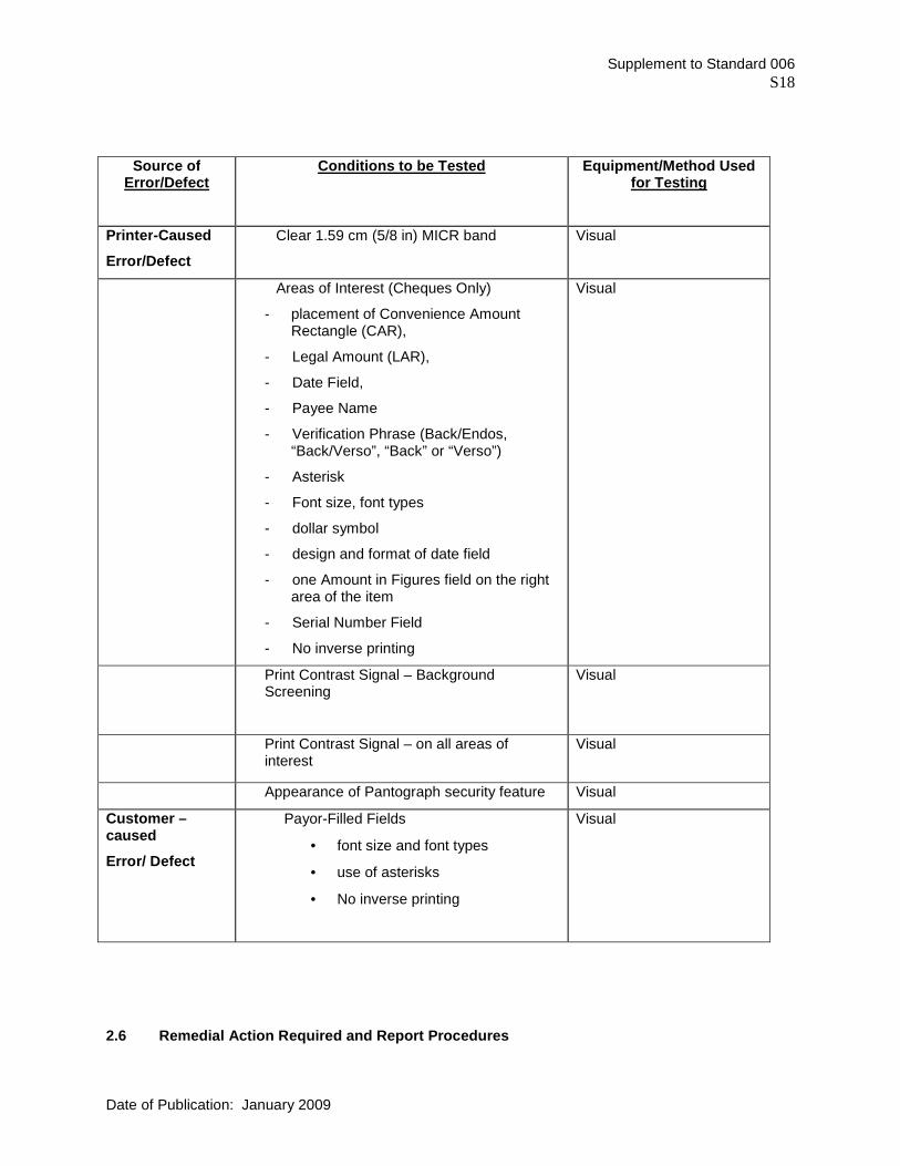
Supplement to Standard 006 S18
Date of Publication: January 2009
Source of Error/Defect
Conditions to be Tested Equipment/Method Used for Testing
Printer -Caused
Error/Defect
Clear 1.59 cm (5/8 in) MICR band
Visual
Areas of Interest (Cheques Only)
- placement of Convenience Amount Rectangle (CAR),
- Legal Amount (LAR),
- Date Field,
- Payee Name
- Verification Phrase (Back/Endos, “Back/Verso”, “Back” or “Verso”)
- Asterisk
- Font size, font types
- dollar symbol
- design and format of date field
- one Amount in Figures field on the right area of the item
- Serial Number Field
- No inverse printing
Visual
Print Contrast Signal – Background Screening
Visual
Print Contrast Signal – on all areas of interest
Visual
Appearance of Pantograph security feature Visual
Customer – caused
Error/ Defect
Payor-Filled Fields
• font size and font types
• use of asterisks
• No inverse printing
Visual
2.6 Remedial Action Required and Report Procedures

Supplement to Standard 006 S19
Date of Publication: January 2009
Follow-up procedures on the evaluation of imageable MICR document rejects will depend on the identification of the source of the errors/defects and the statistical findings of volumes and frequencies of Imageable MICR document rejects stemming from a particular source which, at the member's own discretion, warrant remedial action.
Procedures
a) Printer-Caused Errors/Defects
i) Obtain additional specimen documents from own member/branch for complete
evaluation in accordance with the standard "Sampling Plan for the Inspection of MICR-Encoded Documents" (page S7-S8).
ii) Prepare a "Quality Assurance Evaluation Report" for Imageable MICR documents
not meeting Standard 006, Part A.
iii) Forward copies of completed "Quality Assurance Evaluation Report" to the member branch and/or printer.
iv) Ensure that unacceptable Imageable MICR-encoded documents are reprinted
and new samples are received and evaluated in accordance with "CPA Standard Procedures for the Evaluation of Imageable MICR-Encoded Documents" .
b) CPA Member-Caused Errors/Defects
Own Member
i) Report immediately all unusual or extreme conditions to the processing centre
department or member branch concerned, e.g.:
� encoding unit malfunction � reader/sorter malfunction � machine operator error � member branch personnel error or negligence.
ii) Ensure that reported conditions are corrected.
Other Member
Report immediately all unusual or extreme conditions to the other member's quality assurance department, e.g.:
� encoding unit malfunction � non-compliance with Standard 006, Part A � customer-caused error/defect (of other member).
c) Customer-Caused Errors/Defects
Report errors/defects to member/branch or customer for remedial action, e.g.:
� incorrect information encoded on document � perforations: non-removal of pin-fed edges or stubs � mutilations � folds (especially those resulting from using undersized envelopes) � payor-filled fields: font sizes, font types, and use of asterisks.