can/bottle convertible cb700 - vending … convertible cb700. table of contents ... vending machine...
TRANSCRIPT

APR 2002 P/N 4211254REV E
MODEL 3151
ServiceManual
CAN/BOTTLECONVERTIBLE
CB700

TABLE OF CONTENTS
C B 7 0 0 3 1 5 1 4 2 1 1 2 5 4ii
SPECIFICATIONS ... . . . . . . . . . . . . . . . . . . . . . . . . 1INTRODUCTION ... . . . . . . . . . . . . . . . . . . . . . . . . . . 1UNPACKING ... . . . . . . . . . . . . . . . . . . . . . . . . . . . . . . 3INSTALLATION... . . . . . . . . . . . . . . . . . . . . . . . . . . . 4
Grounding (Earthing) & Electrical ................ 4Power Switches ........................................ 5Hinge and Door Removal ............................ 6
LOADING PRODUCTS ... . . . . . . . . . . . . . . . . . . . 7Product Columns...................................... 7Drop Sensor Adjustment ............................ 9
CONTROLLER ... . . . . . . . . . . . . . . . . . . . . . . . . . . 11Service Mode Button.................................11Keypad Function During Service Mode ........11Standard Controller ..................................12
Errors Mode...........................................13Column Test Vend Mode ..........................14Cash Counter Mode.................................14Sale Counter Mode..................................14Selection Price Mode...............................15Set Vending Depth Mode..........................16Coin Tube Fill Mode.................................16Coin Payout Mode...................................17Refrigeration Parameters Mode..................17
Extended Controller Option........................19Password Mode......................................20Return to Sales/Greeting Mode ..................20Discounted Sale Counter mode..................20Differential Cash Discounted Counter Mode ..21Set Discount Pricing Mode ........................21Space to Sales Mode...............................21Configuration Mode .................................24Time and Timer Settings Mode...................25Time and Date Setting Mode......................26Refrigeration Parameters Mode..................29External Menu Password Setting Mode ........31International Language Setting Mode...........32Exact Change Value Mode........................32External Menu ........................................32
Program Troubleshooting ..........................34
VEND CYCLE ... . . . . . . . . . . . . . . . . . . . . . . . . . . . 35Stand-By Condition.................................. 35Establishing Credit .................................. 35Valid Selection ........................................ 35Vend Sequence ....................................... 35Product Delivery...................................... 35Sold-Out................................................. 36Resetting Sold-Out Selections ................... 36
REFRIGERATION... . . . . . . . . . . . . . . . . . . . . . . . 37Refrigeration Troubleshooting ................... 37
Compressor will not start.......................... 38Compressor trips on Overload................... 39Noisy or vibrating unit.............................. 39Unit short cycles ..................................... 40Unit operates long or continuously .............. 40Refrigerated space too cold ...................... 40Refrigerated space too warm..................... 40Troubleshooting circuits with Multi-Meter...... 41
PREVENTIVE MAINTENANCE ... . . . . . . . 43Once a Month.......................................... 43
Clean Cabinet Interior.............................. 43Clean Cabinet Exterior............................. 43
Every 60-days ......................................... 43Clean Refrigeration Intake Screen.............. 43
Every 6-months....................................... 43Clean the Condenser Coil and Rear ExhaustScreen................................................. 43
PARTS ORDERING PROCEDURE ... . . . . 44BEFORE CALLING FOR SERVICE... . . . 45SCHEMATIC... . . . . . . . . . . . . . . . . . . . . . . . . . . . . . 46ANTI-CHEAT INSTALLATION ... . . . . . . . . 48
Record the Model Number and Serial Number of your machine below.
The Model and Serial numbers are needed for you to obtain quick service andparts information for your machine. The numbers are given on the identificationplate located on the backside of the cabinet of the machine.
MODEL NUMBER:
SERIAL NUMBER:
C B 7 0 0 3 1 5 1 4 2 1 1 2 5 4 1
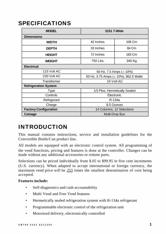
SPECIFICATIONSMODEL 3151 7-Wide
Dimensions
WIDTH 42 Inches 106 Cm
DEPTH 33 Inches 84 Cm
HEIGHT 72 Inches 183 Cm
WEIGHT 750 Lbs. 340 Kg
Electrical115 Volt AC 60 Hz, 7.5 Amps (± 10%)230 Volt AC 50 Hz, 3.75 Amps (± 10%), 862.5 WattsTransformer 24 Volt AC
Refrigeration SystemType 1/3 Plus, Hermetically Sealed
Controls ElectronicRefrigerant R-134a
Charge 8.5 OuncesFactory Configuration 14 Columns, 12 SelectionsCoinage Multi-Drop Bus
INTRODUCTIONThis manual contains instructions, service and installation guidelines for theConvertible Bottle/Can product line.
All models are equipped with an electronic control system. All programming ofthe vend functions, pricing and features is done at the controller. Changes can bemade without any additional accessories or remote parts.
Selections can be priced individually from $.05 to $99.95 in five cent increments(U.S. currency). When adapted to accept international or foreign currency, themaximum vend price will be 255 times the smallest denomination of coin beingaccepted.
Features include:
• Self-diagnostics and cash accountability
• Multi Vend and Free Vend features
• Hermetically sealed refrigeration system with R-134a refrigerant
• Programmable electronic control of the refrigeration unit
• Motorized delivery, electronically controlled

2 C B 7 0 0 3 1 5 1 4 2 1 1 2 5 4
CAUTIONThis vendor utilizes DC motors. Do not attempt to turn by hand. Motordamage could occur.
• Visual feedback indicates when a product has been vendedor when an error condition exists
• No change or loss of program/memory because a power failure
• Cash accountability records Total Cash transactions and Total Vendcycles performed by the vendor. Information for individual selections,complete range (columns), or total machine can be compiled and used forinventory and ordering records.
The vending sequence is “first-in, first-out” for each selection, eliminating theneed for stock rotation to maintain fresh products in the vend area.
Read this manual thoroughly to become familiar with the functions of allcomponents, along with the features that are available. The initial set-up of avending machine is a very important step of insuring that the equipment operatesin a trouble-free manner. Following the instructions during the initial installationof the machine will avoid service problems and minimize set-up time.
Should you have any questions pertaining to information in the manual,replacement parts or the operation of the vendor you should contact your localdistributor or:
VendNet™165 North 10th StreetWaukee, Iowa 50263 - USAPhone: 515-274-3641Parts Fax: 515-987-4447Sales Fax: 515-274-0390E-Mail: [email protected]
C B 7 0 0 3 1 5 1 4 2 1 1 2 5 4 3
UNPACKINGThis vendor was thoroughly inspected before leaving the factory and the deliveringcarrier has accepted responsibility for this vendor. Note any damage orirregularities at the time of delivery and report them to the carrier. Request awritten inspection report from the claims inspector to file any claim for damage.File the claim with the carrier (not the manufacturer) within 15 days after receiptof the machine.
Carefully remove outsidepacking material to avoiddamage to the finish orexterior of the machine.Remove adhesive residuewith denatured alcohol orcommon household vinegar.
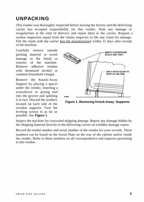
Remove the Knock-AwaySupport by placing a spacerunder the vendor, inserting ascrewdriver or prying toolinto the groove and splittingit in two. Discard the washerslocated on each side of thewooden supports. Turn theleveling screws in as far aspossible. See Figure 1.
Inspect the machine for concealed shipping damage. Report any damage hidden bythe shipping material directly to the delivering carrier on a hidden damage report.
Record the model number and serial number of the vendor for your records. Thesenumbers can be found on the Serial Plate on the rear of the cabinet and/or insidethe vendor. Refer to these numbers on all correspondence and inquiries pertainingto this vendor.
Figure 1. Removing Knock-Away- Supports

4 C B 7 0 0 3 1 5 1 4 2 1 1 2 5 4
INSTALLATIONConsult local, state, and country codes and regulations before installation of thevendor.
CAUTIONTo insure reliability and maintain manufacturers equipment warranty,machine must NOT be placed in an environment where the temperatureis greater than 90°F/32°C and the relative humidity is 65% or greater.
1. Position the vendor in its place of operation no further than six (6) feet(2 m) from the power outlet or receptacle.
WARNINGDO NOT USE EXTENSION CORDS. Extension cords can causeproblems.
2. Leave at least six (6) inches (15 cm) of space between the back of the machineand any wall or obstruction for proper air circulation.
3. Retrieve the keys to the vendor from the coin return cup.4. Open outer door and remove all internal packing material.5. Check that the door will open fully without interference.6. Level the vendor, making sure all levelers are touching the floor. The vendor
must be level for proper operation and acceptance of coins through the coinmechanism.
GROUNDING (EARTHING) & ELECTRICALBefore connecting thevendor, the integrity of themain electrical supply mustbe checked for correctpolarity, presence of ground(earth) and correct voltage.These checks should berepeated at 6-monthintervals with the routinesafety electrical testing ofthe vendor itself.
For proper operation of anyequipment utilizingelectronically controlledcomponents, the equipment should be placed on an isolated or dedicated noise-freecircuit.
Figure 2. 230-Volt Outlets

C B 7 0 0 3 1 5 1 4 2 1 1 2 5 4 5
For 115-Volt vendors the circuitshould be a minimum 15 Amp, 60cycle, properly polarized andgrounded (earthed).
For 230-Volt vendors the circuitshould be a minimum 7.5 Amp, 50cycle, properly polarized andgrounded (earthed).
To verify that the receptacle is properly grounded (earthed) and polarized, insertone probe of a Multi-Meter (set to check AC line voltage) or a test light in theground (earth) terminal (hole) and the other probe into the hot terminal of theoutlet. If unfamiliar with this procedure, contact a licensed electrician.
If the receptacle is not properly grounded (earthed) or polarized, you shouldcontact a licensed electrician to correctly polarize and/or ground (earth) thereceptacle to ensure safe operation.
A noise suppressor has been installed in this machine to compensate for any signalnoise that could interfere with the normal operation of the controller.
Shown in Figure 2 and Figure 3 are two properly grounded (earthed) andpolarized wall outlets. Figure 2 shows two 230-Volt wall outlets.
POWER SWITCHESThe vendor has a door switchoperated by the outer door. Itis located in the lower rightcorner of the cabinet. Whenthe door is closed, the switchis pushed in to the ONposition, putting the vendorin the Sales Mode. When thedoor is opened, the switch isforced to the OFF positionallowing the vendor to be putin Service Mode.
To operate the machine withthe door open, the doorswitch must be manuallypulled out, placing it in analternate ON position.
A power switch is located on the power panel, along with a 3-amp breaker (lowerleft area with door open). With the door open, this switch will shut-off the lightand controller, leaving evaporator fans running. See Figure 4. (The 3-amp breakeris protection for the controller.)
A10674
Figure 4. Power Panel
A10116
Figure 3. 115-Volt Outlet

6 C B 7 0 0 3 1 5 1 4 2 1 1 2 5 4
Figure 5. Upper Hinge Pin
Figure 6. Lower Hinge Pin
HINGE AND DOOR REMOVALRemoval of the upper hinge or the door from the lower hinge from the lower hingepin requires removal of the hinge pin retaining screws. See Figure 5 and Figure 6.
WARNING
Support door before removing upper hinge. Door is very heavy andcould fall causing serious injury.
1. Open the door to approximatelystraight out position.
2. Remove upper and lower hingepin retaining screws.
3. Use wooden blocks to support thedoor. A second person is requiredto steady the door. Upper hingemay now be removed from thevendor.
4. Lift door from lower hinge.Service as required.
5. Replace door on lower hinge.Support door on blocks. A secondpersons is required to steady thedoor while top hinge is installed.
6. Replace the hinge pin retainingscrew.

C B 7 0 0 3 1 5 1 4 2 1 1 2 5 4 7
LOADING PRODUCTS
PRODUCT COLUMNSPoducts being loaded must match theproducts displayed in the Live Display.
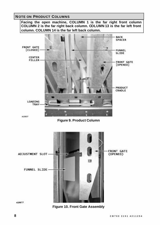
The Funnel Slides (white compositesheets) attached on the sidewalls of eachproduct column must be kept clean. Thisprevents the possibility of a productbridge (product jam) from occuring. SeeFigure 10.
The product cradle “bed” of the ProductDelivery Mechanism must be positionedfacedown in each column to prevent the possibility of a motor jam. The ProductDelivery Mechanisms (Vend Mech) are located at the bottom of each productcolumn. If it is not facedown, cycle the motor to re-position. See Figure 7.
Most products (10 to 20 ounce cans and bottles) may be loaded without columnadjustment. However, the front gate assembly, latch striker, and back spacers maybe adjusted if necessary.See Figure 8.
To adjust column depth(front to back): lift the gateassembly, latch striker, orback spacer and repositionin the adjustment slots.Product should have ¼ to½-inch free space at front orback. See Figure 8,Figure 9 and Figure 10.The front gate assemblywith its latch striker mayhave to be staggeredrelative to an adjacent frontcolumn loaded with similarsized products.
Figure 7. Product DeliveryMechanism (bottom view)
Figure 8. Column Depth
8 C B 7 0 0 3 1 5 1 4 2 1 1 2 5 4
NOTE ON PRODUCT COLUMNSFacing the open machine, COLUMN 1 is the far right front columnCOLUMN 2 is the far right back column. COLUMN 13 is the far left frontcolumn. COLUMN 14 is the far left back column.
Figure 9. Product Column
Figure 10. Front Gate Assembly

C B 7 0 0 3 1 5 1 4 2 1 1 2 5 4 9
NoteStandard 12 oz cans may be double loaded in the front and back,increasing the column capacity.
CAUTIONWhen loading bottled product, make sure that the bottoms of the bottlesface the center of the machine. Load bottles in the back of the machinewith bottom facing the attendant. Load bottles in the front of themachine with top facing the attendant.Do not load dented or damaged cans or bottles in the columns. Possiblejams could occur.Do not store bottles in “spare” space of the cabinet. The refrigerationunit could be damaged.
DROP SENSOR ADJUSTMENTThe delivery chute uses a drop (vibration) sensor to detect whether product isvended after a selection is made. The drop sensor sends a signal to the controllerwhen a product hits the delivery chute. The sensor is attached to the underside ofthe delivery chute.
TO ADJUST DROP SENSOR:1. Loosen the control board cover
mounting screws and removecover.a) Find the five (5) board
mounts. See Figure 10a.
b) Release the control boardfrom the board mounts.Beginning with the topright corner of the controlboard, pinch the boardmounts using a pair ofneedle-nose pliers and pullgently on the circuit board.Follow the same procedureto release the remainingfour (4) board mounts.
Figure 10a. Control Board Mounts

10 C B 7 0 0 3 1 5 1 4 2 1 1 2 5 4
2. Find the drop sensor adjustment screw and the drop sensor indicator light onthe bottom right corner of the control board. See Figure 10b. Set the dropsensor to factory setting as follows:
a) Use a small screwdriver toslowly adjust the adjustmentscrew clockwise (increasesensitivity) and stop when theindicator light comes on.
b) Slowly turn the adjustmentscrew counterclockwise(decrease sensitivity) and stopwhen the indicator light goesout. Now turn the adjustmentscrew counterclockwise 3/4turn. Test the sensor for properoperation by tapping thehopper. The indicator lightshould blink when the hopper istapped.
Figure 10b. Drop SensorAdjustment Screw
c) Re-install the control board back to its mounts. Close the front door andperform several test vends.
d) If vending special products , the drop sensor may need the followingadditional adjustments:
• If machine is sending more than one product per vend request(double vend), then open the door and turn the adjustment screwclockwise 1/4 turn (to increase sensitivity).
• If machine vails to vend product upon vend request, turn adjustmentscrew counterclockwise 1/4 turn (to decrease sensitivity).
3. Re-install control board cover. Close inner and outer doors.

C B 7 0 0 3 1 5 1 4 2 1 1 2 5 4 11
CONTROLLERThe machine must be in Sales Mode to vendproducts.
The machine must be placed in the Service Mode tochange program settings and retrieve diagnosticinformation.
SERVICE MODE BUTTONEnter the Service Mode by simply opening the maindoor and pushing the blue Service Mode Buttonlocated on the middle right side of the control board.See Figure 11. Upon entering the Service Modediagnostic error codes will be displayed if thecontroller has flagged any errors. If credit existswhen entering the Service Mode, it will be restoredwhen the machine is returned to Sales Mode.
CAUTIONElectrostatic discharge can cause majorproblems in the control board. If possibleuse an anti-static conductive wrist strapwhen working with the control board.Always handle electronic boards by theedges, not touching any of the components.
Figure 11. Controller
KEYPAD FUNCTION DURING SERVICE MODE
Table 1. Service Mode Keypad Functions
BUTTON MEANING FUNCTION
UPIncrease, Next,
etc.
DOWNDecrease,
Previous, etc.
ENTER(Press and hold
for less than 2 seconds)
Save, Accept,OK, etc.
After placing the vendor intoService Mode (pressing theblue Service Mode Buttonlocated on the center rightside of the control board),the keypad becomes theinput terminal by which thevendor is programmed. Thefollowing (Table 1) is a listof the four (4) tasksdesignated. HOME
(Press and holdfor more than 2 seconds)
Exit, Escape,Return, etc.

12 C B 7 0 0 3 1 5 1 4 2 1 1 2 5 4
KEYPAD NOTESLetters correspond to Numbers. (A=1, B=2, C=3, D=4, E=5, F=6, G=7,H=8, J=9, L=0)The letters I, K, M, O, S, V, W, X, Y, and Z will not appear on the keypad.Reminders of button codes will be included on each page of thismanual.
STANDARD CONTROLLERRefer to Figure 12 for an overview of the menus available with the StandardController.
The Service Mode menus are accessible only when main door is open. Press theService Mode Button and the display will show “Eror” (Errors Mode), whichmarks the beginning of the Service Menu.
The same control menus are also available in the Extended Controller. Refer toExtended Controller Option on page 19.
Figure 12. Standard Controller Menu Map
C B 7 0 0 3 1 5 1 4 2 1 1 2 5 4 13
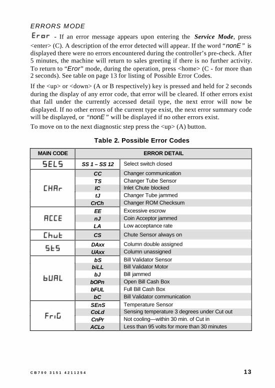
ERRORS MODE - If an error message appears upon entering the Service Mode, press
<enter> (C). A description of the error detected will appear. If the word “nonE” isdisplayed there were no errors encountered during the controller’s pre-check. After5 minutes, the machine will return to sales greeting if there is no further activity.To return to “Eror” mode, during the operation, press <home> (C - for more than2 seconds). See table on page 13 for listing of Possible Error Codes.
If the <up> or <down> (A or B respectively) key is pressed and held for 2 secondsduring the display of any error code, that error will be cleared. If other errors existthat fall under the currently accessed detail type, the next error will now bedisplayed. If no other errors of the current type exist, the next error summary codewill be displayed, or “nonE” will be displayed if no other errors exist.To move on to the next diagnostic step press the <up> (A) button.
Table 2. Possible Error Codes
MAIN CODE ERROR DETAIL
SS 1 – SS 12 Select switch closed
CC Changer communicationTS Changer Tube SensorIC Inlet Chute blockedtJ Changer Tube jammed
CrCh Changer ROM Checksum
EE Excessive escrownJ Coin Acceptor jammedLA Low acceptance rate
CS Chute Sensor always on
DAxx Column double assignedUAxx Column unassigned
bS Bill Validator SensorbiLL Bill Validator MotorbJ Bill jammed
bOPn Open Bill Cash BoxbFUL Full Bill Cash BoxbC Bill Validator communication
SEnS Temperature SensorCoLd Sensing temperature 3 degrees under Cut outCnPr Not cooling—within 30 min. of Cut inACLo Less than 95 volts for more than 30 minutes

14 C B 7 0 0 3 1 5 1 4 2 1 1 2 5 4
COLUMN TEST VEND MODE
- Press <enter> (C) while “tESt” is displayed to enter mode.
Testing by column, not selection, to determine if the proper vend motor isreceiving 24 volts DC from the control board and whether the motor assembly isfunctioning properly.
“CO 1” (Column 1) will be displayed as “tESt” is entered. Press <up> (A) or<down> (B) to display each column to be test vended. Test vend will only beattempted in the columns available on your machine. Pressing <enter> (C) will testthe currently displayed column. While vend is not in process, pressing “home”will return to “tESt” display. From there <down> (B) will go to “Eror”; <up> (A)moves on to “CASH”.
CASH COUNTER MODE - Includes a total count of the cash taken into the machine, which cannot
be reset. Counts include the type (CL=cash level). Each count may be displayed in1 or 2 sets of 4 digits. An example of each:
COUNT TYPE ACTUALCOUNT
1ST
DISPLAY2ND
DISPLAY3RD
DISPLAY
Total Cash Count 29,356.25 CASH 293 56.25Selection Cash Count 9,356.25 CL [number] 93 56.25
Press <enter> (C) while “CASH” is displayed to enter mode.
“CASH” will flash in the display along with the total amount of cash taken into themachine. Press <up> (A) or <down> (B) to display each individual selection cashcount. Press <home> (C - for more than 2 seconds) to return to “CASH” display.From there <down> (B) goes to “tESt”; <up> (A) moves on to “SALE".
FOR EXTENDED CONTROLLER ONLYIndividual selection counts may be reset on the Extended Controlleronly. See Configuration Mode on page 24. If individual counters havebeen configured to reset, they will reset upon reading at least one ofthem and closing the machine door.
SALE COUNTER MODE
- Includes a total count of products vended from the machine, whichcannot be reset. Counts include the type (SL=sale level). Each count may bedisplayed in 1 or 2 sets of 4 digits. An example of each:

C B 7 0 0 3 1 5 1 4 2 1 1 2 5 4 15
COUNT TYPE ACTUALCOUNT
1ST
DISPLAY2ND
DISPLAY3RD
DISPLAY
Total Sale Count 2,935,625 SALE 293 5625Selection Sale Count 935,625 SL [number] 93 5625
Press <enter> (C) while “SALE” is displayed to enter mode.
“SALE” will flash in the display along with the total amount of sales made by themachine. Press <up> (A) or <down> (B) to display each individual selection salecount. Press <home> (C - for more than 2 seconds) to return to “SALE” display.From there <down> (B) goes to “CASH”; <up> (A) moves on to “PriC”.
FOR EXTENDED CONTROLLER ONLYIndividual selection counts may be reset on the Extended Controlleronly. See Configuration Mode on page 24. If individual counters havebeen configured to reset, they will reset upon reading at least one ofthem and closing the machine door.
SELECTION PRICE MODE — Setting vend prices using single or multi-pricing. See Configuration
Mode on page 24 for setting up the machine for single or multi-pricing vending.
Press <enter> (C) while “PriC” is displayed to enter mode. “ALL” will display.
To change/reset all selection price settings [P1 through P14] at the same time, thenpress <enter> (C).
NOTEPressing <enter> (C) with "ALL" displayed will reset all price selections.
The default price setting for all selections displayed is the P1 price setting. Press<up> (A) to increase price [in base units] . Press <down> (B) to decrease price [inbase units] . Press <enter> (C) will save new setting and return to “All” display.
NOTEThe base units value is dependent on the coin mechanism, bill validator,or card reader monetary base unit.
For example: base unit is .05 for US coin mechanisms.
To view/set price settings for selections P1 through P14 separately, then press<up> (A) or <down> (B). The selection number will display followed by theselection price. Press <enter> (C) to change price setting. Press <up> (A) toincrease price. Press <down> (B) to decrease price. Press <home> (C - for morethan 2 seconds) to save the new setting and return to the “Px” (x being theselection number—1 corresponding to button “A”, 2 = “B”, 3=“C”, etc.) display.

16 C B 7 0 0 3 1 5 1 4 2 1 1 2 5 4
The new selection price will also be displayed. From there <home> (C – for morethan 2 seconds) will return to “PriC” the beginning of the Price Mode.
NoteWith the factory default Space to Sales Option 1, P1 will set the price forcolumns 1 and 2, P2 will set the price for columns 3 and 4, P3 will setthe price for column 5, etc…P12 will set the price for column 14. Spaceto Sales Option can only be changed on the Extended Controller Option.
From there <down> (B) goes to “SALE”; <up> (A) moves on to “SdeP”.
SET VENDING DEPTH MODE — Press <enter> (C) while “SdEP” is displayed to enter mode.
Choosing single or double depth for each selection. This is necessary to preventslow vends or multiple vends .
“ALL” will be displayed. Press <enter> (C) to set all the depths the same. Thecurrent depth setting will flash in the display along with “ALL” . Press <up> (A) or<down> (B) to change the depth setting (1 or 2). Press <home> (C - for more than2 seconds) to save setting and return to “ALL” display. Press <home> (C - for morethan 2 seconds) to return to the “SdEP” display. From there <down> (B) goes to“PriC”; <up> (A) moves on to “tUFL".
Save Some Time
Under the “ALL” display, set the single depth setting for themajority of selections. Then change the few that are different byusing the Individual Setting process – Press <up> (A) or <down>(B) while “ALL” is displayed. The individual settings will display.Press <enter> (C) while a selection depth setting is displayedand it will begin to flash. Then press <up> (A) or <down> (B) tochange the depth setting (1 or 2). Press <home> (C - for morethan 2 seconds) to save and lock setting and return to thecurrent selection display. At this point, each selection may beviewed.
COIN TUBE FILL MODE - Press <enter> (C) while “tUFL” is displayed to enter mode.
Maintaining coin tube levels. As coins are added, the mechanism will keep track ofthe exact number of each (denominations do not have to be added in order). Thecontrol board will then keep track of each coin as it is paid out.
CAUTIONUse the “tUFL” mode! Using manual coin payout buttons can result inincorrect coin counts.

C B 7 0 0 3 1 5 1 4 2 1 1 2 5 4 17
Press <home> (C - for more than 2 seconds) to return to “tUFL” display. Fromthere <down> (B) goes to “SdEP”; <up> (A) moves on to “CPo”.
COIN PAYOUT MODE - Testing the control board’s coin payout function.
Press <enter> (C) while “CPo” is displayed to enter mode.
The lowest coin value will be displayed upon entering mode. Press <up> (A) or<down> (B) to display each of the coin values available for payout. Holding <up>(A) or <down> (B) will pay out the denomination of coin currently displayed.Coins will continue to dispense as long as the button is held down. Pressing<home> (C - for more than 2 seconds) will return to the “CPo” display. <down>(B) will then return to “tUFL” and <up> (A) will move the process on to “FriG”.
NOTE
In “tUFL”, “CPo” must be used to pay out coins.
REFRIGERATION PARAMETERS MODE — Controlling environmental aspects of the machine by setting “cut in”
and “cut out” temperatures of the refrigeration unit. The two functions within theRefrigeration Mode are listed below.
STANDARD CONTROLLER
FUNCTION MEANING
Cut In Temperature. Example: 41°F
Cut Out Temperature. Example: 29°F
Press <enter> (C) while “FriG” is displayed to enter mode. “Cuti” will bedisplayed.
Press <up> (A) or <down> (B) to toggle between the two functions. Adjustaccording to need. Press <home> (C - for more than 2 seconds) at any time toreturn to “FriG” display. From there <down> (B) goes to “CPo” and <up> (A)moves to “Eror”.
NoteThe temperature displayed will vary between the “Cuti” and “Cuto”settings and does not reflect the actual product temperature.

18 C B 7 0 0 3 1 5 1 4 2 1 1 2 5 4
CUTI FUNCTION
— Press <enter> (C) to begin setting Cut-In Temperature. The current Cut-In Temperature Setting will be displayed. (Factory preset is 41 F) Press <up> (A)or <down> (B) to change the Cut-In Temperature. (39 –45 F; 4 –7 C) Press<home> (C - for more than 2 seconds) to save changes and return to “Cuti”display. From there <down> (B) or <up> (A) moves on to “Cuto”.
CUTO FUNCTION
— Press <enter> (C) to begin setting Cut-Out Temperature. The currentCut-Out Temperature Setting will be displayed. (Factory preset is 29 F) Press<up> (A) or <down> (B) to change the Cut-Out Temperature. (24 –34 F; -4 –1 C)Press <home> (C - for more than 2 seconds) to save changes and return to “Cuto”display. From there <down> (B) or <up> (A) moves on to moves to “Cuti”.
C B 7 0 0 3 1 5 1 4 2 1 1 2 5 4 19
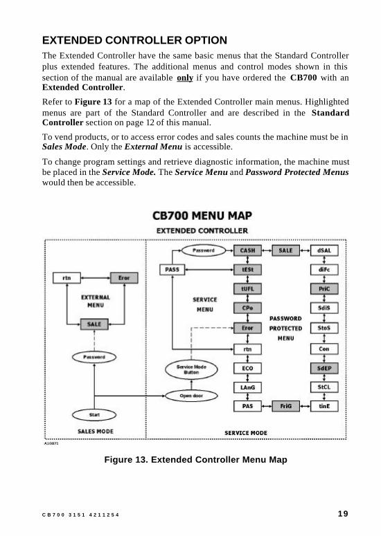
EXTENDED CONTROLLER OPTIONThe Extended Controller have the same basic menus that the Standard Controllerplus extended features. The additional menus and control modes shown in thissection of the manual are available only if you have ordered the CB700 with anExtended Controller.
Refer to Figure 13 for a map of the Extended Controller main menus. Highlightedmenus are part of the Standard Controller and are described in the StandardController section on page 12 of this manual.
To vend products, or to access error codes and sales counts the machine must be inSales Mode. Only the External Menu is accessible.
To change program settings and retrieve diagnostic information, the machine mustbe placed in the Service Mode. The Service Menu and Password Protected Menuswould then be accessible.
Figure 13. Extended Controller Menu Map

20 C B 7 0 0 3 1 5 1 4 2 1 1 2 5 4
PASSWORD MODE
- Accessing Password Protected Menu. All modes necessary for machinesetup are on the Password Protected Menu. A password is required for entry.
Press <enter> (C) while “PASS” is displayed to enter mode.
Enter the initial password by pressing buttons D, B, C, A -- IN THIS ORDER. Ifthe control board fails to recognize the correct password, it will revert to the“PASS” display in 15 seconds.
If the correct password has been entered successfully, “CASH” will be displayed.If no password is entered, <down> (B) will return to “tESt” and <up> (A) willmove on to “rtn”.
RETURN TO SALES/GREETING MODE - Exiting the service menu.
Press <enter> (C) while “rtn” is displayed to return to sales mode and greetingdisplay. From “rtn” <down> (B) goes to “PASS”; <up> (A) moves to “Eror" .
DISCOUNTED SALE COUNTER MODE
- Allows manual retrieval of total product dispensed during discountedsales periods.
Includes a total count of the sales by the machine, which cannot be reset.Individual selection counts may be reset (see Configuration Mode on page 24).Counts include the type (SL=count level). Each count may be displayed in 1 or 2sets of 4 digits. An example of each:
DISCOUNTCOUNT TYPE
ACTUALCOUNT 1ST DISPLAY 2ND
DISPLAY3RD
DISPLAY
Total Sale Count 2935,625 SALE 293 5625Selection Sale Count 935,625 SL [number] 93 5625
Press <enter> (C) while “dSAL” is displayed to enter mode.
“SALE” will flash in the display along with the total amount of sales taken into themachine.
Press <up> (A) or <down> (B) to display each individual selection cash count.Press <home> (C - for more than 2 seconds) to return to “dSAL” display. Fromthere <down> (B) goes to “SALE”; <up> (A) moves on to “diFc".
NOTEIf individual counters have been configured to reset (see ConfigurationMode) they will reset upon reading at least one of them and closing themachine door.

C B 7 0 0 3 1 5 1 4 2 1 1 2 5 4 21
DIFFERENTIAL CASH DISCOUNTED COUNTER MODE - Monitoring the difference between regular prices and discounted prices.
The total count may not be reset. (In this mode, individual counters cannot bereset.) A minus sign (-) indicates that the product was sold for less than the vendprice. Examples:
DIFFERENTIALCOUNT TYPE
ACTUALCOUNT
1ST
DISPLAY2ND
DISPLAY3RD
DISPLAY
Negative DifferentialCash Count -636.25 CASH -6 36.25
Positive DifferentialCash Count 636.25 CASH 6 36.25
Press <enter> (C) while “diFc” is displayed to enter mode.
“CASH” and the total difference between regular vend prices and discountedprices will flash in the display along with the total amount of cash taken into themachine.
Press <home> (C - for more than 2 seconds) to return to “diFc” display. From there<down> (B) goes to “dSAL”; <up> (A) moves on to “PriC".
SET DISCOUNT PRICING MODE — Setting discount prices for each selection. This is done in conjunction
with the built-in timer in “tinE” mode. Before entering the “tinE” mode, selectionsmust be set to “1” in “StCL” mode. The discounted selection may be time-activatedusing the “dScn” setting in the “tinE” mode under the day function.
Press <enter> (C) while “SdiS” is displayed to enter mode.
“ALL” will be displayed along with the last discount price set for “ALL”. Press<up> (A) or <down> (B) to view other set discount prices. Press <enter> (C) tochange a discount price. Hold or press <up> (A) to increase discount price in 5-cent increments. Press <down> (B) to decrease discount price in 5-centincrements. <home> (C - for more than 2 seconds) will save new setting and returnto the selection level display.
Press <home> (C - for more than 2 seconds) again to return to “SdiS” display.From there <down> (B) goes to “PriC”; <up> (A) moves on to “StoS".
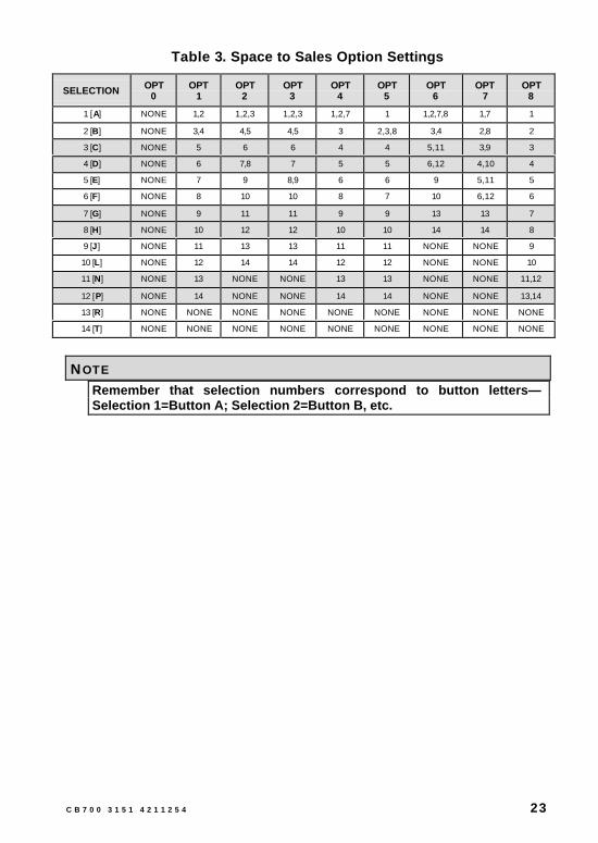
SPACE TO SALES MODE — Determining select button and vend column assignment and assigning
multiple columns to select buttons. Using fewer select buttons allows more of apopular product to be loaded in the columns vended through the “multiple-column ” buttons.
NOTEThere will be a Space to Sales Mode preset from the factory and anavailable custom Space to Sales Mode.

22 C B 7 0 0 3 1 5 1 4 2 1 1 2 5 4
Press <enter> (C) while “StoS” is displayed to enter mode.
Factory Standard Settings: Press <up> (A) or <down> (B) to view each Space toSales setting. Press <enter> (C) to select and lock any factory standard setting(“opt #”). The previous setting will automatically be replaced. The display willthen begin to sequence through each selection followed by each columnassignment. Pressing <home> (C - for more than 2 seconds) will return to “StoS”.
EXAMPLE:After selecting a factory setting, “SL1” is displayed, followed by “1” andthen “2”. This means that selection 1 has been assigned to columns 1and 2.
Custom settings: Press <enter> (C) at the “CStS” (<down> (B) from “oPt 0”)display option. “SL 1” (selection 1) will display followed by each column assignedto this selection. (See example above) Press <up> (A) or <down> (B) to movethrough each of the 12 available selections and their assigned columns. (Rememberthat column numbers will correspond to button letters on the keypad .)
Press <enter> (C) at any selection to enter the column display. “Co 1” for instance— "Co" indicating “column ” followed by its number. Press <up> (A) or <down>(B) to view each column designation. If a column designator is flashing, it isassigned to that selection. If it is not flashing, it is not assigned. Press <up> (A) or<down> (B) to change the column from its current assignment mode (columnassignment will be flashing); then press <enter> (C) to add or delete a columnfrom its current selection assignment. <home> (C - for more than 2 seconds) willreturn to the Selection display with flashing column number. Reassign otherselections in the same manner. <home> (C - for more than 2 seconds) again willreturn to the “CStS” display. New assignments will override existing assignments.
When finished, press <home> (“C” for more than 2 seconds) to return to “StoS”display. From there <down> (B) goes to “SdiS”, <up> (A) moves on to “Con”.
C B 7 0 0 3 1 5 1 4 2 1 1 2 5 4 23
Table 3. Space to Sales Option Settings
SELECTION OPT0
OPT1
OPT2
OPT3
OPT4
OPT5
OPT6
OPT7
OPT8
1 [A] NONE 1,2 1,2,3 1,2,3 1,2,7 1 1,2,7,8 1,7 1
2 [B] NONE 3,4 4,5 4,5 3 2,3,8 3,4 2,8 2
3 [C] NONE 5 6 6 4 4 5,11 3,9 3
4 [D] NONE 6 7,8 7 5 5 6,12 4,10 4
5 [E] NONE 7 9 8,9 6 6 9 5,11 5
6 [F] NONE 8 10 10 8 7 10 6,12 6
7 [G] NONE 9 11 11 9 9 13 13 7
8 [H] NONE 10 12 12 10 10 14 14 8
9 [J] NONE 11 13 13 11 11 NONE NONE 9
10 [L] NONE 12 14 14 12 12 NONE NONE 10
11 [N] NONE 13 NONE NONE 13 13 NONE NONE 11,12
12 [P] NONE 14 NONE NONE 14 14 NONE NONE 13,14
13 [R] NONE NONE NONE NONE NONE NONE NONE NONE NONE
14 [T] NONE NONE NONE NONE NONE NONE NONE NONE NONE
NOTERemember that selection numbers correspond to button letters—Selection 1=Button A; Selection 2=Button B, etc.
24 C B 7 0 0 3 1 5 1 4 2 1 1 2 5 4
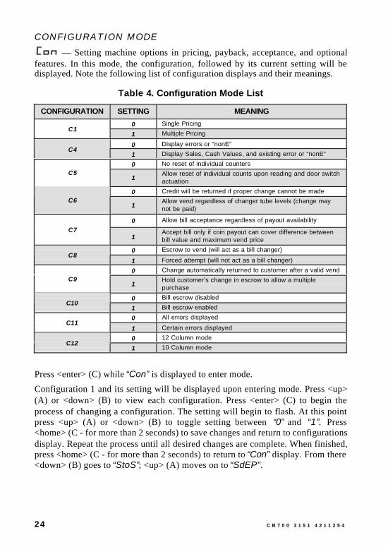
CONFIGURATION MODE — Setting machine options in pricing, payback, acceptance, and optional
features. In this mode, the configuration, followed by its current setting will bedisplayed. Note the following list of configuration displays and their meanings.
Table 4. Configuration Mode List
CONFIGURATION SETTING MEANING
0 Single PricingC1
1 Multiple Pricing
0 Display errors or “nonE”C4
1 Display Sales, Cash Values, and existing error or “nonE”
0 No reset of individual countersC5
1Allow reset of individual counts upon reading and door switchactuation
0 Credit will be returned if proper change cannot be madeC6
1Allow vend regardless of changer tube levels (change maynot be paid)
0 Allow bill acceptance regardless of payout availability
C71
Accept bill only if coin payout can cover difference betweenbill value and maximum vend price
0 Escrow to vend (will act as a bill changer)C8
1 Forced attempt (will not act as a bill changer)
0 Change automatically returned to customer after a valid vendC9
1Hold customer’s change in escrow to allow a multiplepurchase
0 Bill escrow disabledC10
1 Bill escrow enabled
0 All errors displayedC11
1 Certain errors displayed
0 12 Column modeC12
1 10 Column mode
Press <enter> (C) while “Con” is displayed to enter mode.
Configuration 1 and its setting will be displayed upon entering mode. Press <up>(A) or <down> (B) to view each configuration. Press <enter> (C) to begin theprocess of changing a configuration. The setting will begin to flash. At this pointpress <up> (A) or <down> (B) to toggle setting between “0” and “1”. Press<home> (C - for more than 2 seconds) to save changes and return to configurationsdisplay. Repeat the process until all desired changes are complete. When finished,press <home> (C - for more than 2 seconds) to return to “Con” display. From there<down> (B) goes to “StoS”; <up> (A) moves on to “SdEP".

C B 7 0 0 3 1 5 1 4 2 1 1 2 5 4 25
TIME AND TIMER SETTINGS MODE — Turning off selections with timer or optional key switch kit. Selections
set to “1” will allow control by timer or key switch. “0” selections will function aspreset.
Press <enter> (C) while “StCL” is displayed to enter mode. “ALL” will bedisplayed. Press <enter> (C) again. “ALL” will display without flashing and thecurrent “StCL” setting will flash. Press <up> (A) or <down> (B) to change settingbetween “0” and “1” . Press <home> (C - for more than 2 seconds) to save changeand return to “ALL”.
Cycle through selections using <up> (A) or <down> (B) to change individualsettings. Press <enter> (C) at any setting to change that setting using <up> (A) or<down> (B). Press <home> (C - for more than 2 seconds) to save setting andreturn to “StCL”. From there <down> (B) will go to “SdEP” and <up> (A) willmove to “tinE”.

26 C B 7 0 0 3 1 5 1 4 2 1 1 2 5 4
TIME AND DATE SETTING MODE — Setting ON and OFF times for selections, refrigeration, and/or lighting.
Date and time must be set properly for this mode to function.
The following is a chart of functions, their meanings, and an example of each:
Table 5. Time and Date Mode Functions
FUNCTION ITEM DISPLAY EXAMPLE
Current year “99” (1999)
Current month/day “0907” (Sept 7)
Current hour/min. “1520” (3:20 pm)
Set day of week “Fri” (Friday)Disable clock “CLOC” then “StOP”
Timer on/off days and times “ALL”
Display time on LED “dSt” w/flashing setting
Daylight Savings Time “dLt” w/flashing setting
NOTEDisable Clock is used during machine storage time to conserve thecontrol board battery life.
Press <enter> (C) while “tinE” is displayed to enter mode.
“YEAr” will be the first item displayed. Press <up> (A) or <down> (B) to movethrough the “tinE” options. Pressing <home> (C - for more than 2 seconds) at anytime while moving through the options will return “tinE” to the display. Fromthere pressing <down> (B) will move to “StCL”. Press <up> (A) to move to“FriG”.
YEAR FUNCTION
— Press <enter> (C) to begin setting year function. Press <up> (A) or<down> (B) to change the 2-digit year (it should be flashing). Press <home> (C -for more than 2 seconds) to save changes and return to “YEar” display. Fromthere <down> (B) moves to “dLt” and <up> (A) moves on to “dAtE”.
DATE FUNCTION
— Press <enter> (C) to begin setting date function. Press <up> (A) or<down> (B) to change the first 2 digits of the date (they should be flashing). Press<enter> (C) to lock that item and move to the next. Repeat the process. Whenfinished, press <home> (C - for more than 2 seconds) to save changes and return to“dAtE” display. From there <down> (B) moves to “YEAr” and <up> (A) moveson to “hour”.
C B 7 0 0 3 1 5 1 4 2 1 1 2 5 4 27
HOUR FUNCTION
— Press <enter> (C) to begin setting hour function (in military time).Press <up> (A) or <down> (B) to change the first 2 digits of the time (they shouldbe flashing). Press <enter> (C) to lock that item and move to the next. Repeat theprocess. When finished, press <home> (C - for more than 2 seconds) to savechanges and return to “hour” display. From there <down> (B) moves to “dAtE”and <up> (A) moves on to “SEtd”.
SETD FUNCTION
— Press <enter> (C) to begin setting “SEtd” function. Press <up> (A) or<down> (B) to change the day of the week. When finished, press <home> (C - formore than 2 seconds) to save changes and return to “SEtd” display. From there<down> (B) moves to “hour” and <up> (A) moves on to “StOP”.
STOP FUNCTION
— Press <enter> (C) to begin process of turning off clock. Press <enter>(C) again. This turns off the clock and automatically exits back to the “StOP”display. (<enter> (C) acts like a toggle switch in this instance.) When finished,press <home> (C - for more than 2 seconds) to save changes and return to“StOP” display. From there <down> (B) moves to “SEtd” and <up> (A) moveson to “dAY”.
DAY FUNCTION
— Press <enter> (C) to begin adjustment of the “dAY” function. (Fromhere the timer is set for each day of the week.) “ALL” will be displayed. There arenow 2 options to choose from —”ALL” or individual days of the week. <up> (A)or <down> (B) will move through the various days. Press <enter> (C) at a day ofthe week or “ALL” (“ALL” being the option from which to set the same timerpattern for all days of the week). “SC-1” will be displayed followed by “On”.From there press <up> (A) or <down> (B) to cycle through all other availabletimer setting modes. See table on page 28.

28 C B 7 0 0 3 1 5 1 4 2 1 1 2 5 4
Table 6. Day Function Setting Modes
SETTING MODE MEANING
SC-1…On 1st OFF time for selectionsSC-1…Off 1st ON time for selections
SC-2...On 2nd OFF time for selectionsSC-2…Off 2nd ON time for selections
SC-3…ON 3rd OFF time for selectionsSC-3…OFF 3rd ON time for selections
DScn…On ON time for discounted selectionsDScn…Off OFF time for discounted selections
FriG…On OFF time for refrigeration systemFriG…Off ON time for refrigeration system
Lt-1…On 1st OFF time for lightingLt-1…Off 1st ON time for lighting
Lt-2…On 2nd OFF time for lightingLt-2…Off 2nd ON time for lighting
Lt-3…On 3rd OFF time for lightingLt-3…Off 3rd ON time for lighting
At any Timer Mode press <enter> (C) to initiate a change in the ON and OFFtimes setting. The current setting with the hour flashing will be displayed. Press<up> (A) or <down> (B) to change the hour of this setting. Press <enter> (C) tolock the change and move to the minutes. Repeat the process. When finished, press<home> (C - for more than 2 seconds) to save changes and return to the timersetting modes listing display. From there <up> (A) or <down> (B) moves to theother timer setting modes. Each may be adjusted using the same process. Press<home> (C - for more than 2 seconds) to return to the day of the week level. Press<home> (C - for more than 2 seconds) again to return to the “dAY” display. Fromthere <down> (B) goes to “StOP”; <up> (A) moves on to “dSt”.
NOTEFor selections which are set to go off and come back on at particulartimes the first off time for selections must be set from “SC-1”. The firstreturn on time for the selections must be set by entering “SC-1Off”.Selections to be controlled must be set in the “StCL” mode of thePassword Protected Menu.
DST FUNCTION
— Press <enter> (C) to begin setting Display Time Setting mode. Press<up> (A) or <down> (B) to change the current setting (flashing) “1” indicates thatthe time of day will be displayed on the LED during the greeting. “0” indicatesthat the time will not be displayed during the greeting. When finished, press

C B 7 0 0 3 1 5 1 4 2 1 1 2 5 4 29
<home> (C - for more than 2 seconds) to save changes and return to “dSt”display. From there <down> (B) moves to “dAY” and <up> (A) moves to “dLt”.
DLT FUNCTION
— Press <enter> (C) to begin setting Daylight Savings Time Enable/Disablemode. “dLt” will be displayed along with the current setting (flashing). Press<up> (A) or <down> (B) to change the current setting. “1” indicates that DaylightSavings Time is enabled. “0” indicates that Daylight Savings Time is disabled.When finished, press <home> (C - for more than 2 seconds) to save changes andreturn to “dLt” display. From there <down> (B) moves to “dSt” and <up> (A)moves on to “YEAr”. Press <home> (C - for more than 2 seconds) to return to“tinE” (beginning of function menu). From there <down> (B) moves to “StCL”and <up> (A) moves to “FriG”.
REFRIGERATION PARAMETERS MODE — Controlling environmental aspects of the machine by setting “cut in”
and “cut out” temperatures of the refrigeration unit. The various functions withinthe Refrigeration Mode are listed below.
EXTENDED CONTROLLER OPTION
FUNCTION MEANING
Cut In Temperature. Example: 43°F
Cut Out Temperature. Example: 29°F
Select Fahrenheit or Celsius
Display Inside Cabinet (evaporation) Temperature
Master control ON/OFF
Relay Test Mode
Press <enter> (C) while “FriG” is displayed to enter mode. “Cuti” will bedisplayed.
Press <up> (A) or <down> (B) to move through all six “FriG” functions. Adjustaccording to need. Press <home> (C - for more than 2 seconds) at any time toreturn to “FriG” display. From there <down> (B) goes to “tinE” and <up> (A)moves to “PAS”.
NoteThe temperature displayed will vary between the “Cuti” and “Cuto”settings and does not reflect the actual product temperature.

30 C B 7 0 0 3 1 5 1 4 2 1 1 2 5 4
CUTI FUNCTION
— Press <enter> (C) to begin setting Cut-In Temperature. The current Cut-In Temperature Setting will be displayed. (Factory preset is 41 F) Press <up> (A)or <down> (B) to change the Cut-In Temperature. (39 –45 F; 4 –7 C) Press<home> (C - for more than 2 seconds) to save changes and return to “Cuti”display. From there <down> (B) moves to “rELY” and <up> (A) moves on to“Cuto”.
CUTO FUNCTION
— Press <enter> (C) to begin setting Cut-Out Temperature. The currentCut-Out Temperature Setting will be displayed. (Factory preset is 29 F) Press<up> (A) or <down> (B) to change the Cut-Out Temperature. (24 –34 F; -4 –1 C)Press <home> (C - for more than 2 seconds) to save changes and return to “Cuto”display. From there <down> (B) moves to “Cuti” and <up> (A) moves on to“dEG”.
DEG FUNCTION
— Press <enter> (C) to change current Degree Setting. “dEG” will bedisplayed along with the current setting. Press <up> (A) or <down> (B) to change(“F” for Fahrenheit (factory preset) or “C” for Celsius). When finished, press<home> (C - for more than 2 seconds) to save change and return to “dEG”display. From there <down> (B) moves to “Cuto” and <up> (A) moves on to“dSP”.
DSP FUNCTION
— Press <enter> (C) to begin setting the Display Temperature function.“dSP” will be displayed along with the current setting (flashing). Press <up> (A)or <down> (B) to change the current setting. “1” indicates that the temperaturewill be displayed along with the sales greeting. “0” indicates that the temperaturewill not be displayed along with the sales greeting. When finished, press <home>(C - for more than 2 seconds) to save changes and return to “dSP” display. Fromthere <down> (B) moves to “dEG” and <up> (A) moves on to “FrG”.
NoteThe temperature displayed will vary between the “Cuti” and “Cuto”settings and does not reflect the actual product temperature.
FRG FUNCTION
— Press <enter> (C) to use the Unit Disable function (Master ON/OFF).“FrG” will be displayed along with the current setting (flashing). Press <up> (A)or <down> (B) to change the current setting (“1” for normal operation (factorypreset) or “0” to disable the unit). When finished, press <home> (C - for more

C B 7 0 0 3 1 5 1 4 2 1 1 2 5 4 31
than 2 seconds) to save change and return to “FrG” display. From there <down>(B) moves to “dSP” and <up> (A) moves on to “rELY”.
RELAY TEST FUNCTION
— Press <enter> (C) to begin working in the Relay Test Function. “Fan”will be displayed. Press <up> (A) or <down> (B) to move through each relay testfunction. The test functions are listed below.
Table 7. Relay Test Functions
FUNCTION TEST TYPE
Fan Evaporator Fan Relay Test (requires opt. kit)
LitE Illumination Relay Test (requires optional kit)
Htr Heater Relay Test (requires optional kit)
CnPr Compressor Relay Test
Press <enter> (C) at any of the 4 function modes. The name of the relay will flashand then “OFF” or “ON”. To change setting press <down> (B). To leave it as set,press <home>. This allows the name of the relay to flash and then flash off. If therelay is turned off but is to be tested, press <enter> (C) to test. If the circuit doesnot work, Test Mode is maintained for 5 minutes to give time for a voltage check.Press <home> (C - for more than 2 seconds) to return (after a test) to the display ofthe tested menu item. Press <home> (C - for more than 2 seconds) from this pointto return to the “rELY” display. When finished, press <home> (C - for more than2 seconds) to save change and return to “FriG” display. From there <down> (B)moves to “tinE” and <up> (A) moves on to “PAS”.
EXTERNAL MENU PASSWORD SETTING MODE — Setting a password to externally access historical and individual
selection can counts, and machine errors. (Factory preset password is A-C-B-D)
NOTE
This menu will always display the current password.Available password letters are A-J (note—only those alpha buttonsassigned to a selectionSet one of the password letters to “J” or to an unavailable selection todisable external password.
Press <enter> (C) to begin setting password. The current password will bedisplayed. (IT WILL BE DISPLAYED NUMERICALLY—A=1, B=2, C=3, ETC)The first digit will flash. Press <up> (A) or <down> (B) to change the digit. Press<enter> (C) to lock and save the new choice. Repeat procedure for other 3 digits.

32 C B 7 0 0 3 1 5 1 4 2 1 1 2 5 4
<enter> (C) after the fourth digit will return to the first digit. Press <home> (C -for more than 2 seconds) to return to “PAS” display. From there <down> (B) willmove to “FriG” and <up> (A) will go to “LAnG”. (Note and remember thepassword by alpha buttons for ease of entry later.)
INTERNATIONAL LANGUAGE SETTING MODE — Changing display to alternate language.
Press <enter> (C) to begin setting language. The current language will bedisplayed. Press <up> (A) or <down> (B) to change the language. Press <home>(C - for more than 2 seconds) to lock and save the new choice and return to the“LAnG” display. From there <down> (B) will move to “PAS” and <up> (A) willgo to “ECO”. The following languages are available:
EnGL English
FrEn French
SPAn Spanish
HEbr Hebrew
GEr German
EXACT CHANGE VALUE MODE
— Controlling the Exact Change Only value. (Indicating that the machinecannot make change at or below the value specified.)
Press <enter> (C) to begin setting Exact Change Only value. The current exactchange value will be displayed. Press <up> (A) or <down> (B) to change thevalue. Press <home> (C - for more than 2 seconds) to lock and save the newchoice and return to the “ECO” display. From there <down> (B) will move to“LAnG” and <up> (A) will go to “rtn”. From there <up> (A) will move to thevery beginning of the service menu (“Eror”).
EXTERNAL MENUThis menu is primarily used to access error codes and sales counts. The main doordoes not have to be open to enter this menu. Entering the correct 4-alpha buttonpassword while the machine is in stand-by accesses the External Menu. Stand-Byindicates that the greeting is displayed, credit is not established, and free vend isnot set.
This menu gives access to total and individual (per selection) vend counts,machine error diagnostics, and a clearing feature for individual vend counts. Thismenu does not provide programming ability. Machine will return to sales modeafter 5 minutes.

C B 7 0 0 3 1 5 1 4 2 1 1 2 5 4 33
SALE COUNTER MODE
— Extracting information concerning the amount of product vended. Thetotal count cannot be reset, but individual selection counts may be reset ifconfigured accordingly. See Configurations on page 24.
The type precedes counts. Each count may be displayed in 1 or 2 sets of 4 digits.Refer to Table 8. Sale Counter Mode Examples .
Table 8. Sale Counter Mode Examples
COUNT TYPE ACTUALCOUNT
1ST
DISPLAY2ND
DISPLAY3RD
DISPLAY
Total Sale Count 2,935,625 SALE 293 5625Selection Sale Count 935,625 SL [number] 93 5625
Press <enter> (C) while “SALE ” is displayed to enter mode.
“SALE” will flash in the display along with the total amount of sales made by themachine.
Press <up> (A) or <down> (B) to display each individual selection sale count.Press <home> (C - for more than 2 seconds) to return to the “SALE” display.From there <down> (B) will move to “Eror” and <up> (A) will go to “rtn” (ifpresent). (Selection number will correspond to alpha buttons in order.)
RETURN TO SALES/GREETING MODE
— Exiting the External Menu, and returning to Sales Mode and GreetingDisplay.
Press <enter> (C) while “rtn” is displayed to return to Sales Mode and GreetingDisplay. From there <down> (B) will go to “SALE” and <up> (A) will move to“Eror”.
ERRORS MODE
— Diagnosing Machine problems. In this mode, any errors will bedisplayed. “None” indicates that no errors were found and the display will returnto “Eror” on the External Menu. This mode is for display of information only--Errors must be cleared from the Internal Service Menu.
Press <enter> (C) while “Eror” is displayed to enter mode.
All current machine errors will be displayed followed by a description of each, or“None” will indicate that there are none. Press <home> (C - for more than 2seconds) to return to the “Eror” display. From there <down> (B) will go to “rtn”.

34 C B 7 0 0 3 1 5 1 4 2 1 1 2 5 4
PROGRAM TROUBLESHOOTINGImproper programming can cause unexpected results. Refer to the followingtroubleshooting guide:
Table 9. Program Troubleshooting Guide
PROBLEM REFER TO CONTROLLER MENU
Wrong prices. Selection Price Mode on page 15
Wrong or incorrect columns vending. Space to Sales Mode on page 21
Options improperly setup. Configuration Mode on page 24
Multiple or “long” vend cycles. Set Vending Depth Mode on page 16
Selections do not work when timer orkey switched is activated.
Time and Timer Settings Mode onpage 25
Selections are not working.
Refrigeration system is not working.
Time and Date Setting Mode onpage 26
Refrigeration system is not working.
Temperature is too warm or too cold.
Refrigeration Parameters Mode onpage 17 for Standard Controller, andpage 29 for Extended Controller.
Can not access the external passwordmode.
External Menu Password SettingMode on page 31
Displays wrong messages or wronglanguage.
International Language SettingMode on page 32
Refer also to Table 2. Possible Error Codes on page 13.

C B 7 0 0 3 1 5 1 4 2 1 1 2 5 4 35
VEND CYCLE
STAND-BY CONDITIONThe greeting, vend price (if all are set to the same value), and a choice of otheroptional features will be displayed. If a customer presses a select button beforeestablishing a credit, the vend price for that selection will be displayed, signalingthe customer that more money is needed for that selection.
ESTABLISHING CREDITFeeding coins into the coin mechanism results in the display of the correspondingcredit count. The coin mechanism will accept coins until the highest vend price hasbeen reached. At this point a credit has been set up through the control board thatwill enable a vend for any selection less than or equal to the established credit.
VALID SELECTIONMaking a selection causes the selection switch to close. A logic level signal isconstantly sent out from the control board that then travels to each switch’scommon position. When the switch is closed, the signal travels out the normallyclosed position to the harness connection to the control board.
VEND SEQUENCEThe control board then distributes 24 volts DC through the door and cabinet wiringharnesses and to the coil of the selection vend motor. At the same time, the displaywill scroll. This indicates to the customer that a vend is in progress. As the vendmotor receives power, it will turn the rotor, attempting to vend a can or bottle.
PRODUCT DELIVERYAs the can or bottle drops onto the product delivery chute, the impact vibrationallows the delivery sensor to send a low voltage signal to the control boardindicating that a product has been vended. After receiving the sensor signal, thecontrol board will recognize how the machine is programmed and respondaccordingly.
If the first can or bottle has just vended the control board will stop all power to thevend motor at the same time that the impact is registered, thus avoiding a multiplevend. As the next can or bottle vends, the control board will cycle the vend motorto pick up another can or bottle, thus allowing a quick vend turnaround of less than3 seconds.

36 C B 7 0 0 3 1 5 1 4 2 1 1 2 5 4
NOTEThe control board will use a Learning Mode to determine which is thefront or rear product. This process is reset either on powering down orup or a door opening or closing. The Learning Mode acts in conjunctionwith the depth setting to enable automatic reload after the rear producthas vended.The controller will note the first “long-timed out” vend cycle during thelearning process. From this the controller will determine that the nextvend will be front product.
SOLD-OUTThe display will cycle to show the vend progress of each selection. If a productdrop is not detected in 10 to 12 seconds, “Sold Out ” will be displayed. “SoldOut” may be due to:
• Selected column is jammed.
• Column is actually sold out.
• Sensor does not detect product drop and needs adjustment.
• Selection does not have a column assigned.
At the “Sold Out” display, the customer may make a different selection or receivea refund by pressing the coin return lever. If the machine is set for forced purchase,the customer must make an initial selection. If the initial selection is sold out, a fullrefund or an alternate selection will be allowed. If the machine is totally sold outof all products, the “Sold Out” display will be continuous and no money will beaccepted into the machine.
RESETTING SOLD-OUT SELECTIONSOnly opening the machine door will clear a sold out condition (which activates themachine door switch). The controller will not attempt a vend until this is done.Pressing a select button will only initiate the “Sold Out” display.

C B 7 0 0 3 1 5 1 4 2 1 1 2 5 4 37
REFRIGERATION
NOTETo prevent damage to the refrigeration unit when it is turned off or thepower interrupted, the refrigeration unit will not restart for at least threeminutes regardless of the temperature.
When the temperature is above the programmed cut-in temperature, therefrigeration unit is turned on. Upon reaching the cut-out temperature therefrigeration unit is turned off.
If the refrigeration unit runs continuously for more than four hours withoutreaching the cut-out temperature, the unit is turned off for the programmed twenty(20) minute defrost time. It will then be turned on again automatically.
REFRIGERATION TROUBLESHOOTINGIf the refrigeration unit is turned off, or the power is interrupted, or the door isopened, then the refrigeration unit will not start for at least three minutesregardless of the temperature. This is done to prevent damage to the refrigerationunit.
CAUTIONBreaking the refrigerant joints or seals on the system voids the unitwarranty. Failure to keep the condenser coil clean and free of dirt anddust and other similar debris voids the unit warranty.
Know and understand how the unit operates. Units may vary, but the operation isbasically the same. Never guess at the problem; find the symptom beforeattempting any repair.
NOTE
Most refrigeration problems are electrical.
The sealed hermetic system should not be worked on outside the Factory ServiceCenter. The three things that can go wrong with a sealed system and should berepaired only at the Factory Service Center are:
• Low Charge - usually caused by leaks; look for oil around sealsand welds. Unit will not cool properly. The capillary tube isfrosted before it enters the evaporator inlet tube.
• Restriction in Systems (unit frosts, then melts) - not coolingproperly.
• Bad valves - unit does not cool properly; noisy compressor.

38 C B 7 0 0 3 1 5 1 4 2 1 1 2 5 4
COMPRESSOR WILL NOT START• Compressor has no power
• Machine not plugged in
• Tripped breaker or blown fuse
• Faulty wall outlet
• Short or open in power cord
• Temperature sensor circuit is open (check with a Multi-Meter)
• Improper wiring
• Low voltage: 5% below (check the power source with a Multi-Meter)
• Overload defective: Trips too fast (check overload with a Multi-Meter)
• Start relay defective (check start relay with a Multi-Meter)
• Compressor has open windings (check compressor windings with aMulti-Meter)
• Defective refrigeration relay
• Unplug power to the machine; remove the relay plate. Use an insulatedjumper wire to short the wires on relay terminals 2 and 4 or 6 and 8;then restore power to the machine. The compressor should startimmediately, indicating a problem in the control circuit.Check relay terminals 1 to 0 with a Multi-Meter. 24VDC should bepresent.
• No DC voltage (check control board output terminal for a looseconnection)

C B 7 0 0 3 1 5 1 4 2 1 1 2 5 4 39
COMPRESSOR TRIPS ON OVERLOAD
• Improper voltage: 5-10% above, 5% below (check power source with aMulti-Meter)
• Overload defective: Trips too fast (check overload with Multi-Meter)
• Relay defective: Won’t open after starting (check relay with Multi-Meter)
• Compressor has shorted windings (check compressor windings withMulti-Meter)
• Short in other component (isolate and eliminate each electricalcomponent until short is found)
• Compressor is too hot
♦ Dirty condenser
♦ Faulty condenser motor or blade
♦ Restricted airflow
CAUTIONCondenser must be kept clean of dirt and debris to allow for proper aircirculation.
NOISY OR VIBRATING UNIT
• Components rubbing or touching each other
♦ Check fan blades and motor
♦ Loose shrouds and harness
♦ Copper tubing
♦ Loose or unsecured parts
♦ Dirty condenser fan blades
• Worn or aged compressor grommets
• Compressor
♦ Bad valves
♦ Slugging
♦ Bad windings (see Schematic)
♦ Low voltage

40 C B 7 0 0 3 1 5 1 4 2 1 1 2 5 4
UNIT SHORT CYCLES
• Temperature sensor defective or not mounted in the Discharge air duct
• Defective control board
• Temperature setting set too warm (see Refrigeration Parameters Modeon page 17 of this manual)
UNIT OPERATES LONG OR CONTINUOUSLY
• Temperature Sensor defective or not mounted in the Discharge airduct
• Refrigeration relay shorted
• Air flow restricted
♦ Faulty evaporator motor or blades causing coils to ice
♦ Loose connections on evaporator motor
♦ Air flow blocked by product in front of evaporator
♦ Exhaust area blocked (machine too close to wall)
• Gasket leak around door
• Excessive load: After loading, unit runs longer to pull out excessiveheat from product
• Shortage of refrigerant or restriction
• Bad controller
• Ambient air temperature and relative humidity exceed manufacturersoperational standards
REFRIGERATED SPACE TOO COLD
• Temperature sensor defective (check with Multi-Meter)
• Refrigeration control setting too cold (see Refrigeration ParametersMode on page 17 of this manual)
• Refrigeration relay bad (check with Multi-Meter)
• Faulty control board
REFRIGERATED SPACE TOO WARM
• Temperature sensor defective (check with Multi-Meter)
• Refrigeration control setting too warm (see Refrigeration ParametersMode on page 17 of this manual)
• Refrigeration relay bad
• Faulty control board
• Restricted evaporator space

C B 7 0 0 3 1 5 1 4 2 1 1 2 5 4 41
♦ Evaporator motor or blades faulty, causing the coils to ice over theevaporator
♦ Condenser airflow restricted
♦ Plugged or dirty condenser
♦ Condenser motor or blades bad
♦ Blade stuck
♦ Condensing space restricted
♦ Unit placed too close to a wall
• Compressor - bad valves
♦ Capillary tube will start frosting 8 to 10 inches (20-25 cm) beforeevaporator connection tube
♦ Check for oil around brazed connections
TROUBLESHOOTING CIRCUITS WITH MULTI-METER
• To check the power source, use the voltage section of the Multi-Meter(should measure within 5-10% above, 5% below)
• Check overloadUsing the resistance section of the Multi-Meter, check terminals 1 and3 for continuity. If no continuity is measured (infinity), overload may betripped. Wait 10 minutes and try again. If still no continuity, overload isdefective.
CAUTIONPower must be off and fan circuit open.
• Check relay (See Figure 14.) Unscrew lead terminals and removerelay from compressor. Keep relay upright.
• Check terminals 1 and S, or L and S with the Multi-Meter. Replacerelay if continuity exists.
• Check Temperature sensor with the Multi-Meter.
• Check compressor windings as shown in Figure 14.
• Check winding resistance with the Multi-Meter. If readings are notwithin 2 Ohms, the compressor is faulty. Use RX1 scale.
WARNINGWiring diagrams must be followed as shown. Incorrect wiring can causeserious electrical hazard and potential damage or rupture componentelectrical parts.

42 C B 7 0 0 3 1 5 1 4 2 1 1 2 5 4
Table 10. Winding Resistance
APPROX. RESISTANCE ACROSS TERMINALS
COMMON to START: 12 OhmsCOMMON to RUN: 2 Ohms
RUN to START: 14 OhmsCOMMON to SHELL: No Continuity
Figure 14. Compressor Schematic

C B 7 0 0 3 1 5 1 4 2 1 1 2 5 4 43
PREVENTIVE MAINTENANCE
ONCE A MONTH
CAUTIONAlways disconnect power source BEFORE cleaning or servicing.
CLEAN CABINET INTERIOR
Wash with a mild detergent and water, rinse, and dry thoroughly. Including bakingsoda or ammonia in the cleaning solution may eliminate odors. Plastic parts maybe cleaned with a quality plastic cleaner. Remove and clean Condensate DrainHose to eliminate any deposits that may restrict condensate water flow.
The vend mechanisms must be kept clean. Any build-up can cause the mechanismsto malfunction.Do not get the cleaning solution on electrical components.
To insure proper vending keep delivery slide area free of dirt and stickysubstances.
CLEAN CABINET EXTERIORWash with a mild detergent and water, rinse, and dry thoroughly. Polishoccasionally with a quality car wax. Plastic exterior parts may be cleaned with aquality plastic cleaner.
EVERY 60-DAYS
CLEAN REFRIGERATION INTAKE SCREENRemove screen and clean dust and debris from screen using a soft bristle brush ora vacuum cleaner.
EVERY 6-MONTHS
CLEAN THE CONDENSER COIL AND REAR EXHAUSTSCREENRemove the Cover Assembly and clean the condenser coil of refrigeration unitusing a soft bristle brush or vacuum cleaner.
Pull the refrigeration unit and clean the rear exhaust screen of dirt anddebris.
Do not block the evaporator or any area of the airflow with product orsupplies.

44 C B 7 0 0 3 1 5 1 4 2 1 1 2 5 4
PARTS ORDERING PROCEDUREWhen ordering parts, include the following:
1. The model number and serial number of the machine.2. Shipping address.3. Address where the invoice should be sent.4. The number of parts required.5. Any special shipping instructions.6. Carrier desired: air or air special, truck, parcel post, or rail.7. Signature and date.8. If a purchase order number is used, be sure that it is visible and legible.9. Correct part number and description from the pertinent part and/or parts
manual.
NOTEWhen “Right” and “Left” are used with a part name, it is taken to meanthat the person is facing the machine with the door closed.
10. Mail your order to: VendNet
165 North 10th Street
Waukee, Iowa 50263 - USA
Phone: 515-274-3641
Parts Fax: 515-987-4447
Sales Fax: 515-274-0390
E-Mail: [email protected]
All orders are carefully packed and inspected before shipment. Damage incurredduring shipment should be reported at once and a claim filed with the terminatingcarrier.
If you do not have the right parts manual, contact the above address.VendNet will provide a copy for you, if available.
Do not wait to order until you receive the parts manual; instead use the mostaccurate description you can. Include the model number and serial number of themachine, the name of the assembly in which the part is used, and if practical, asample part. Furnish any information to enable our Parts Department to pinpointthe exact part needed.
C B 7 0 0 3 1 5 1 4 2 1 1 2 5 4 45
BEFORE CALLING FOR SERVICEPlease check the following:
• Does your machine have at least 6-inches of clear air space behind it?
• If the power is turned on at the fuse box, is the machine the only thing thatdoesn’t work?
• Is the machine plugged directly into the outlet?
WARNINGExtension cords can cause problems.DO NOT USE EXTENSION CORDS.
• Is the evaporator coil free of dust and dirt? Is the condenser coil free of dustand dirt?
• Is the compressor free of dust?
• Is the circuit breaker at the fuse box reset?
• Are evaporator fans running? To check if fans are running take a small pieceof paper in front of the evaporator coil and see if the evaporator fans will blowthe paper away.
• Is the condenser fan running? Place a piece of paper in front of the condensercoils and see if it draws the paper to it.
• Is the shelf in front of the evaporator coil clear? (No tools, product, or otherair-restricting items).
• Is the cold control set as specified?
NOTESetting the temperature colder does not accelerate cooling of product.

46 C B 7 0 0 3 1 5 1 4 2 1 1 2 5 4
SCHEMATIC

C B 7 0 0 3 1 5 1 4 2 1 1 2 5 4 47

48 C B 7 0 0 3 1 5 1 4 2 1 1 2 5 4
ANTI-CHEAT INSTALLATION
WARNINGTo avoid electrical shock when performing service, disconnect theelectrical power. Do not remove electrical components and partswithout first unplugging the power cord from the power source.
1. Unlock and open the door. Separate the Inner Door from the Front Doot.
2. Find the Delivery Box on the bottom right corner of the Front Door as viewedfrom behind the Front Door. Remove the Delivery Box from the Front Doorby removing the bolt nuts. See Figure 15.
Figure 15. Remove Delivery Box mounting nuts.
3. Remove the four (4) nuts holding the Delivery Bezel and save them for step 4.Insert the Anti-Cheat through the Delivery Bezel rectangular hole.See Figure 16.

C B 7 0 0 3 1 5 1 4 2 1 1 2 5 4 49
Figure 16. Insert Anti-Cheatthrough Front Door opening.
Figure 17. Install and tighten nuts.
4. Mount the Anti-Cheat slotted mounting holes over the mounting bolts of thedoor as shown in Figure 17. Re-install nuts removed from step 3 and tightenthem.
5. Re-install the Delivery Box.
6. Close the Inner Door to the Front Door. Plug the machine to the wall outletand turn on power.
7. Close the Front Door and perform test vends.

The contents of this publication are presented for informational purposes only, and while every effort has been made to ensure their accuracy, theyare not to be construed as warranties or guarantees, express or implied, regarding the products or services described herein or their use orapplicability. We reserve the right to modify or improve the designs or specifications of such products at any time without notice.
VendNet™165 North 10th StreetWaukee, Iowa 50263
United States of America
USA & Canada International
Service (800) 833-4411
Parts (888) 259-9965(515) 274-3641
Email [email protected]
Web Site www.vendnetusa.com4211254E.DOC