canvas 12 user guide - acdsee...
TRANSCRIPT

User Guide

Notice of LiabilityThe information in this manual is distributed on an "As Is" basis, without any representation orwarranty of any kind whether express or implied, including any implied warranty of merchantability,title or fitness for a particular purpose or use. While every precaution was taken in the preparation ofthis manual, neither the author nor ACD Systems of America, Inc. shall have any liability to anyperson or entity with respect to any loss or damage caused or alleged to have been caused directly orindirectly in connection with the use or inability to use the instructions contained in this manual. ACDSystems reserves the right to make changes to this manual without notice.
Trademarks and CopyrightsCanvas Software was designed, programmed and is Copyright © 2010 ACD Systems of America, Inc.Canvas, SpriteEffects, SpriteLayers, Dynamic Objects, SmartMouse, and SmartLines are trademarksof ACD Systems of America, Inc. and may be registered in certain jurisdictions. All Rights ReservedWorldwide.
All other brands, trademarks, product and company names are the property of their respectiveholders.
ACD and the ACDSee logo are trademarks of ACD Systems International Inc. or its subsidiary and areused under license by ACD Systems of America, Inc.
Adobe, Acrobat, FrameMaker, Illustrator, Photoshop, PostScript and Reader are either registeredtrademarks or trademarks of Adobe Systems Incorporated in the United States and/or othercountries.
Apple, Macintosh, and TrueType are trademarks of Apple Inc., registered in the U.S. and othercountries.
Canon is a registered trademark of Canon Inc. Code by Niles Ritter, Copyright © 1995 Niles D. Ritter.
Contains an implementation of the LZW algorithm licensed under U.S. Patent 4,558,302 and foreigncounterparts.
CLIP ART Copyright © 1986-2005 ACD Systems of America, Inc.
Corel, CorelDRAW, Paint Shop Pro, Quattro Pro and WordPerfect are trademarks or registeredtrademarks of Corel Corporation and/or its subsidiaries in Canada, the United States and/or othercountries.
DWG is the native file format for Autodesk’s AutoCAD® software and is a trademark of Autodesk, Inc.
DXF is a drawing interchange of Autodesk’s AutoCAD® software and is a trademark of Autodesk, Inc.
Excel, Freelancer, Microsoft, PowerPoint, Visio, Windows, Windows logo, Windows Vista andWindows Vista Start button are either registered trademarks or trademarks of Microsoft Corporationin the United States and/or other countries.
FONTS are registered trademarks of URW++ Design & Development GmbH.

Canvas 12 User Guide
GeoSpatial Data Abstraction Library, Copyright © 2000, Frank Warmerdam.
"Harvard Graphics " is a registered trademark of Serif.
Kodak Color Management Systemand Photo CD are trademarks and KODAK is a registered trademarkof Eastman Kodak Company.
libTIFF,Copyright © 1988-1997 Sam Leffler, Copyright © 1991-1997 Silicon Graphics, Inc.
Oracle® Outside In Viewer Technology. Copyright 2010 Oracle, and/or its affiliates. All rightsreserved
PANTONE® Computer Video simulations used in this product may not match PANTONE-identifiedsolid color standards. Use current PANTONE Color Reference Manuals for accurate color.
PANTONE Color Computer Graphics © Pantone, Inc. 1986, 1988.
Pantone, Inc. is the copyright owner of PANTONE Color Computer Graphics and Software which arelicensed to ACD Systems of America, Inc to distribute for use only in combination with Canvas.PANTONE Color Computer Graphics and Software shall not be copied onto another diskette or intomemory unless as part of the execution of Canvas.
Shapefile C Library Copyright © 1999, FrankWarmerdam.
The Proximity/Merriam-Webster Hyphenation System ©1990 Merriam-Webster, ©1990 All rightsreserved Proximity Technology, Inc.
This software is based in part on the work of the Independent JPEGGroup.
This software contains portions of imaging code owned and copyrighted by Pegasus Imaging Corp.,Tampa FL, ALL RIGHTS RESERVED.
CopyrightManual Copyright © 2010 ACD Systems of America, Inc. All Rights Reserved Worldwide.
This manual may not be copied, photocopied, reproduced, translated, or converted to any electronicor machine readable form in whole or in part without prior written consent of ACD Systems ofAmerica, Inc.
Canvas was designed, programmed and is Copyright © 2010 ACD Systems of America, Inc. All RightsReserved Worldwide. Software is covered by a separate license agreement.
First Edition: July 2010
Part Number: C0710-0007-EN
Contact InformationACD Systems of America
www.acdsee.com
Contents
CHAPTER 1: INTRODUCTION 1
Welcome To Canvas 12 2
What's New In Canvas 12 2
Technical Illustration And Enhancement With Greater Control 3
Even Greater Workflow Integration 4
Additional Capabilities For Publishing, Presenting And Collaborating 9
Enhanced Usability 10
About The Documentation 11
Keyboard Keys 11
Choosing Commands 11
Contacting ACD Systems And Updating Canvas 12
Enter License Code 12
Product Support And Resources 12
Customer Support 13
Product Registration 13
Community 13
Related Products 13
Purchase Canvas 13
Verify Document 13
Getting Help With Canvas 13
Using The Help 13
Showing The Startup Screen 14
Using The Canvas Assistant 14
Using The Dynamic Help 14
CHAPTER 2: DOCUMENTS AND SETUP 17
Running Canvas 18
v

Canvas 12 User Guide
Starting And Exiting Canvas 18
Overview Of The Canvas Interface 19
Canvas Window 19
Layout Area 21
Document Navigation Controls 21
Viewing The Smart Toolbox 22
Using AutoSnap Palettes 25
Using The Toolbar 27
Using The Properties Bar 28
Using The Docking Bar 33
Using The Docking Pane 36
Dynamic Help 37
Using The Status Bar 38
Viewing Documents 39
Changing The View Magnification 41
Using Expressions For Numeric Values 45
Using Context-sensitive Menus 46
Document Basics 47
Opening Canvas Documents 47
Placing Documents 49
Saving Canvas Documents 50
Saving Files 51
Saving Selections And Layers 51
Applying Password Protection To Canvas Documents 52
Undoing, Redoing, And Repeating Actions 53
Reverting To The Saved Version Of A Document 55
Working With Document Windows 55
Viewing And Editing Document Properties 56
Printing Documents 58
vi

Closing Documents 68
Document Setup 68
Creating New Documents 68
Illustrations 70
Publications 70
Presentations 71
Animations 71
Setting Up Documents 72
Setting Up Rulers 74
Document Scale Methods 77
Using The Alignment Grid 80
Using Alignment Guides 81
Document Layout 82
About Document Pages And Layers 83
Pages 83
Layers 83
Master Pages 84
Using The Page Navigator Palette 85
Using The Document Layout Palette 85
Page And Layer Controls 90
Page And Layer Options 91
Using Guide And Grid Layers 95
Configuration & Customization 97
Setting Preferences 97
General Settings 100
Text Settings 110
Printing Settings 115
Measurements Settings 117
Image/multimedia Settings 120
vii

Canvas 12 User Guide
Color Management 120
Preferences For Two-byte Text Entry 123
Customizing The Keyboard And Toolbar 124
Saving Document Templates 128
File & Data Exchange 129
Importing And Exporting Files 129
Exporting Files 130
Importing And Exporting Images 131
Importing Images 131
Exporting Images 132
Using Canvas Templates 133
Working With Other File Formats 134
Using Object Linking And Embedding 151
Inserting ActiveX Controls In Documents 154
Exporting Files To Canvas Using The Canvas Print Driver 154
CHAPTER 3: OBJECTS AND ATTRIBUTES 157
Working With Objects 158
Types Of Objects 158
Selecting Objects 158
Selecting Objects With Selection Tools 159
Editing Objects 162
Copying, Cutting, Pasting, And Deleting Objects 164
Making Multiple Copies 171
Grouping And Ungrouping Objects 177
Moving Objects 178
Arranging Objects In The Stacking Order 180
Arranging Objects On Layers And Pages 180
Locking And Unlocking Objects 181
viii
Aligning And Distributing Objects 181
Rotating, Skewing, And Flipping Objects 186
Scaling Objects 195
Scaling Objects By Area/Perimeter 196
Using The Object Specs Palette 197
Setting Print Properties For Objects 201
Creating Attribute Styles 203
Setting Default Attributes 205
Attaching Comments To Objects And Using Markup Tools 206
Assigning And Modifying Custom Object Properties 210
Viewing Object Properties 217
Inks: Colors & Patterns 223
Presets Palette 223
Attributes Palette 229
Working With Gradient Inks 238
Working With Hatch Inks 244
Working With Symbol Inks 246
Working With Texture Inks 248
Working With Pattern Inks 249
Creating Favorite Inks 251
Applying Inks To Objects 252
Using The Color Dropper 254
Replacing Ink Attributes 257
Strokes: Outline Effects 257
Types Of Strokes 257
Applying Preset Strokes 260
Customizing Strokes 271
Creating Custom Arrowheads 281
Customizing Dashes 283
ix

Canvas 12 User Guide
CHAPTER 4: DRAWING AND VECTOR EFFECTS 285
Drawing Basics 286
Drawing Basic Shapes 286
Drawing Shapes 287
Drawing With Snap Options 292
Drawing By Numbers 294
Drawing More Complicated Shapes 295
Using The Smart Vector Fill Tool 307
Adding Annotations 308
Creating Flowcharts 311
Using Math Expression 2-D Plot Commands 314
Drawing & Editing Paths 316
Drawing With The Path Tools 317
Editing Object Paths 324
Reshaping Paths By Editing Anchor Points 338
Simplifying Vector Paths 348
Converting Polygons To Bézier Objects 348
Joining Open Vector Objects 349
Exporting And Importing Geometric Data 350
Editing Views Of 3D Objects 353
3D View Editor Dialog Box 355
Precision Drawing & Dimensioning 356
Setting Up A Document’s Measurement Scale 356
Using The Dimensioning Tools 358
Using Smart Mouse For Precise Alignment 366
Vector Effects 371
Perspective Effects 371
Offsetting Paths 374
Using Clipping Paths 374
x

Combining Objects 377
Blending Objects 381
Enveloping Objects 384
Extruding Objects 387
Colorizing Objects 392
Fractalizing Objects 393
Creating Shadows For Objects 394
Binding Objects To Path 396
Dynamic Objects & Clipart 397
Working With The Symbol Library Palette 397
Creating New Symbols 401
Modifying Preinstalled Symbols 402
Converting Macro Files To Symbols 403
CHAPTER 5: PAINTING AND IMAGE EDITING 405
Painting & Image-editing 406
Paint Objects And Images 406
Creating Paint Objects 406
Working With Painting Tools 410
Selecting Brushes And Painting Options 420
Selecting Colors For Painting 423
Painting Modes 424
Painting Context Menu 426
Adding Visibility Masks To Images 428
Rendering Objects And Images 430
Using Vector And Text Tools In Paint Objects 433
ImageModes For Canvas Paint Objects 435
Removing Red Eye 445
Scanning, Sizing & Tracing Images 446
xi
Canvas 12 User Guide
Using Scanners To Acquire Images 446
Choosing A Scanning Resolution 447
Changing Image Size 448
Changing Resolution 456
Auto-tracing Images 458
Image Adjustment & Correction 461
Applying Image-editing Commands 461
Consolidating Colors 462
Changing Color And Contrast 465
Color Balance 468
Levels 468
Adjusting Brightness Curves 470
Hue/Saturation 472
Color Equalization 474
Blur Filters 474
Sharpen Filters 479
Adding And Removing Noise 480
Selections & Channels 483
Selecting Pixels In Images 483
Selecting Areas Based On Color 487
Converting Paths To Selections 492
Working With Image Selections 493
Saving And Loading Selections In Channels 501
Using The Channels Palette 504
Customizing Alpha Channels 507
Channel Masks 509
Transparency Effects With Channel Masks 512
Image Filters & Effects 515
Applying Effect Filters 515
xii

Ripple Effects 526
Twirl Effects 529
Spherical Distortion 530
Artistic Effects 532
Using The High Pass, Maximum, And Minimum Filters 538
Filling Selections With Color 541
Creating Custom Image Filters 541
Rotating Images 543
Distorting Images 544
Combining Image Channels 547
Image Proxies 551
Using Proxies 551
Editing Proxies 554
Maintaining Proxies 556
Exporting Canvas Image Files 558
CHAPTER 6: TEXT AND TYPOGRAPHY 559
Text Entry & Layout 560
Typing Text In A Document 560
Using The Text Tool 561
Creating Text Layouts 563
Tools And Options For Two-byte And Vertical Text 564
Creating Column Layouts 567
Flowing Text From Column To Column 573
Text Form Field Tool 576
Formatting Text 577
Selecting Text And Objects 577
Applying Text Formats 580
Specifying Spacing Between Characters 585
xiii
Canvas 12 User Guide
Positioning Tabs 587
Horizontal And Vertical Text Scaling 589
Applying Paragraph Formatting 590
Setting Indents 592
Paragraph Alignment 594
Using Vertical Justification 596
Paragraph Rules 597
Adjusting Letter And Word Spacing 599
Automatic Hyphenation 600
Specifying Text Flow Options 601
Setting Drop Caps 602
Inserting Headers And Footers 603
Working With Type Styles 605
Creating New Type Styles 606
Saving And Loading Type Styles 609
Using Type Styles 610
Applying Character Formatting 612
Text Editing & Proofing 613
Text Edit Mode 613
Text Selection And Navigation 614
Copying, Pasting, Deleting, And Moving Text Selections 616
Automatic Text Correction 620
Inserting Special Characters And Graphics In Text 622
Checking The Spelling Of Text 625
Importing Text FromOther Applications 629
Exporting Text FromCanvas Documents 630
Type Effects 631
Text Inks And Strokes 631
Wrapping And Repelling Text 634
xiv

Binding Text To Vector Objects 637
Applying Vector Effects To Type 643
CHAPTER 7: SPRITE TECHNOLOGY 649
SpriteEffects 650
Introduction To SpriteEffects 650
Using SpriteEffects 650
Using The SpriteEffects Palette 651
Selections Masks 656
Effects Area 657
Lens Effects 659
Sharing Documents With SpriteEffects 665
SpriteLayer Effects 666
Using The Transparency Palette 666
Opacity Effects 667
Controlling The ScopeOf Transparency Effects 670
TransparencyMasks 671
Channel Masks 672
Vector Masks 678
Transparency And Printing 687
CHAPTER 8: MULTIMEDIA 689
Designing For The Web 690
About Hyperlinks And Hypertext 690
Using The Link Manager Palette 691
Pixel Mode 699
Creating Slices 699
Using Web Buttons 708
Working With Animated GIFs 712
Creating Web Pages From Canvas Documents 714
xv
Canvas 12 User Guide
Exporting As A Flash File 720
Exporting As PDF 722
Presentations 728
Creating Slide Shows 728
CHAPTER 9: SEISMIC DATA 735
Seismic Data 736
Importing CGM Files 736
Seismic Traces Palette 738
Control Panel 738
WiggleOptions 739
Background Options 740
CHAPTER 10: VISUALIZATION AND ANALYSIS 743
Data Acquisition, Visualization And Analysis 744
Working With DICOM Images 744
RAW File Format 745
Image Types And Filters 748
Accessing Image Data 763
APPENDICES 769
SystemRequirements 770
Hardware 770
Software 770
INDEX 771
xvi

Chapter 1: Introduction
Canvas 12 User Guide
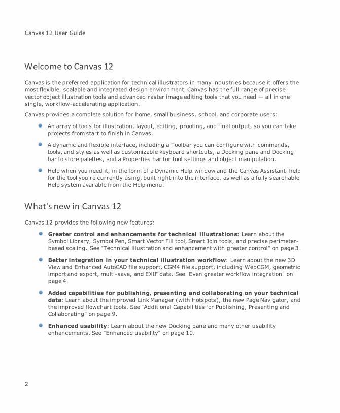
Welcome to Canvas 12
Canvas is the preferred application for technical illustrators in many industries because it offers themost flexible, scalable and integrated design environment. Canvas has the full range of precisevector object illustration tools and advanced raster image editing tools that you need — all in onesingle, workflow-accelerating application.
Canvas provides a complete solution for home, small business, school, and corporate users:
An array of tools for illustration, layout, editing, proofing, and final output, so you can takeprojects from start to finish in Canvas.
A dynamic and flexible interface, including a Toolbar you can configure with commands,tools, and styles as well as customizable keyboard shortcuts, a Docking pane and Dockingbar to store palettes, and a Properties bar for tool settings and object manipulation.
Help when you need it, in the form of a Dynamic Help window and the Canvas Assistant helpfor the tool you're currently using, built right into the interface, as well as a fully searchableHelp system available from the Help menu.
What's new in Canvas 12
Canvas 12 provides the following new features:
Greater control and enhancements for technical illustrations: Learn about theSymbol Library, Symbol Pen, Smart Vector Fill tool, Smart Join tools, and precise perimeter-based scaling. See "Technical illustration and enhancement with greater control" on page 3.
Better integration in your technical illustration workflow: Learn about the new 3DView and Enhanced AutoCAD file support, CGM4 file support, including WebCGM, geometricimport and export, multi-save, and EXIF data. See "Even greater workflow integration" onpage 4.
Added capabilities for publishing, presenting and collaborating on your technicaldata: Learn about the improved Link Manager (with Hotspots), the new Page Navigator, andthe improved flowchart tools. See "Additional Capabilities for Publishing, Presenting andCollaborating" on page 9.
Enhanced usability: Learn about the new Docking pane and many other usabilityenhancements. See "Enhanced usability" on page 10.
2
Chapter 1: Introduction
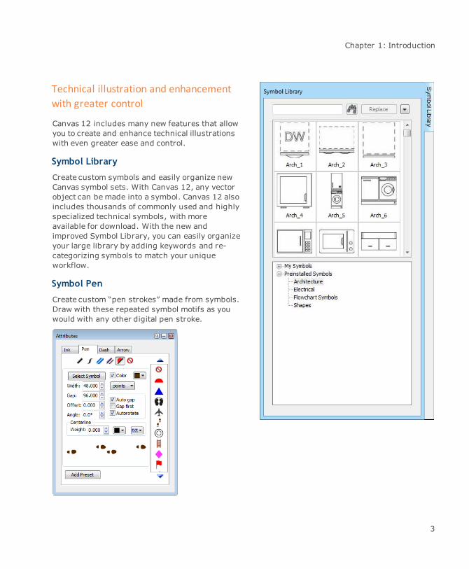
Technical illustration and enhancementwith greater control
Canvas 12 includes many new features that allowyou to create and enhance technical illustrationswith even greater ease and control.
Symbol Library
Create custom symbols and easily organize newCanvas symbol sets. With Canvas 12, any vectorobject can be made into a symbol. Canvas 12 alsoincludes thousands of commonly used and highlyspecialized technical symbols, with moreavailable for download. With the new andimproved Symbol Library, you can easily organizeyour large library by adding keywords and re-categorizing symbols to match your uniqueworkflow.
Symbol Pen
Create custom “pen strokes” made from symbols.Draw with these repeated symbol motifs as youwould with any other digital pen stroke.
3
Canvas 12 User Guide
Smart Vector Fill
Color visually-enclosed regions created by overlapping objects. Whenoverlapping object shapes create a new shapewhere they intersect, you cannow instantly select this shape, and color it, with just one click. Thiseliminates the need to redraw these regions as standalone objects beforeselecting a fill ink.
Smart Join
Use the new Smart Join command to quickly rejoin segmented objects into asingular object.
Precise perimeter-based illustration scaling
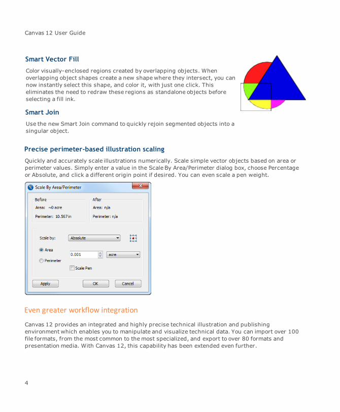
Quickly and accurately scale illustrations numerically. Scale simple vector objects based on area orperimeter values. Simply enter a value in the Scale By Area/Perimeter dialog box, choose Percentageor Absolute, and click a different origin point if desired. You can even scale a pen weight.
Even greater workflow integration
Canvas 12 provides an integrated and highly precise technical illustration and publishingenvironment which enables you to manipulate and visualize technical data. You can import over 100file formats, from the most common to themost specialized, and export to over 80 formats andpresentation media. With Canvas 12, this capability has been extended even further.
4

Chapter 1: Introduction
3D view and enhanced AutoCAD file support
View and enhance the latest AutoCAD® DXF/DWG 3D object file formats. Just import your 3D file, usestep rotation on an X, Y, or Z axis, edit and enhance color, scale, light source, and preview it inWireframe. With Canvas 12, you can now fit seamlessly into AutoCAD® 3D workflows.
5
Canvas 12 User Guide
CGM4 file support, including WebCGM
Import, edit and export CGM and WebCGM files. Canvas 12 can be fully integrated into CGMworkflows because it supports the latest CGM file types, including Version 4 CGM-PIP I/II (PetroleumIndustry Profile), and CGM-ATA (Airline Transportation Association). And now when you import andmodify CGM files, WebCGM tags are retained. After editing and visually augmenting files, export themback into CGM work environments and specialized CGM applications. The Canvas 12 integration intoCGM workflows allows for new possibilities in the visual presentation of CGM files, including on theweb.
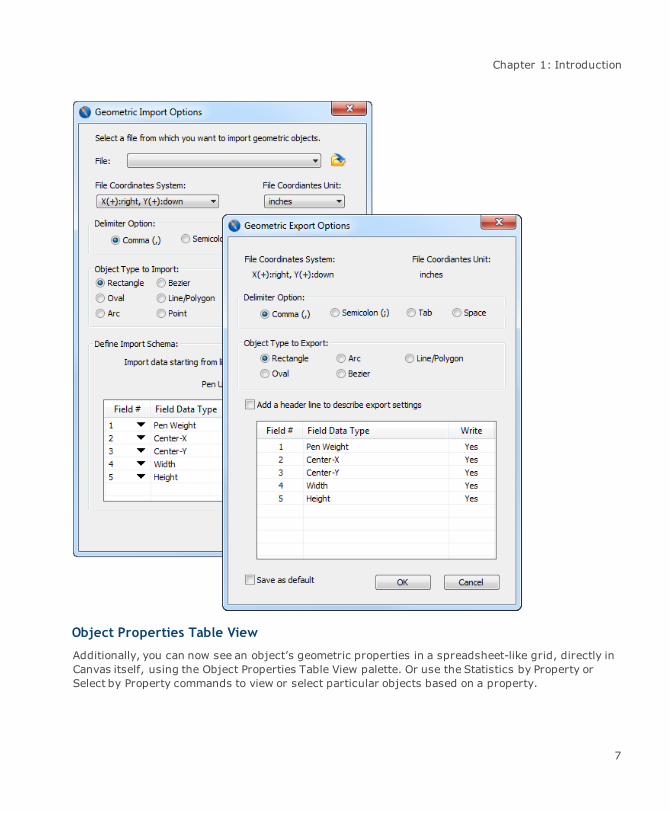
Geometric import and export
Import and export an object’s precise geometry. The new Geometric Import And Export feature letsyou import and exportmathematical data that numerically describes an object’s exact geometry. Thisallows for powerful integration with other applications such as Microsoft® Excel® and specializedsoftware. It also lets you precisely specify and manipulate both the location and geometricdimensions of Rectangles, Ovals, Lines, Polygons, Beziers and Arcs.
6
Chapter 1: Introduction
Object Properties Table View
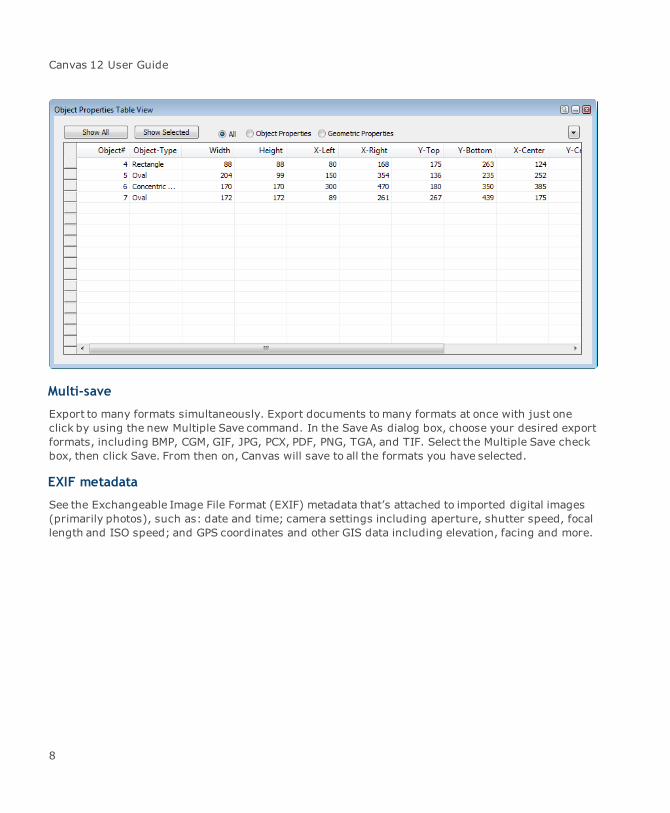
Additionally, you can now see an object’s geometric properties in a spreadsheet-like grid, directly inCanvas itself, using the Object Properties Table View palette. Or use the Statistics by Property orSelect by Property commands to view or select particular objects based on a property.
7
Canvas 12 User Guide
Multi-save
Export to many formats simultaneously. Export documents tomany formats at once with just oneclick by using the new Multiple Save command. In the Save As dialog box, choose your desired exportformats, including BMP, CGM, GIF, JPG, PCX, PDF, PNG, TGA, and TIF. Select the Multiple Save checkbox, then click Save. From then on, Canvas will save to all the formats you have selected.
EXIF metadata
See the Exchangeable Image File Format (EXIF) metadata that’s attached to imported digital images(primarily photos), such as: date and time; camera settings including aperture, shutter speed, focallength and ISO speed; and GPS coordinates and other GIS data including elevation, facing and more.
8

Chapter 1: Introduction
Additional Capabilities for Publishing, Pre-senting and Collaborating
Link Manager (with hotspots)
Add hyperlinks to documents and then exportthem. Create links throughout Canvas documents,making them out of graphics, images, or text.Then export to PDF or HTML with the links intact.You can also create hotspots (linked regionswithin graphics) for PDF export. Use Canvas 12 toadd interactivity and connectivity to yourtechnical documents.
Page Navigator
Easilymove within multiple page documents. Inthe Page Navigator palette you can instantlynavigate within multiple page Illustration,Publication, Animation and Presentationdocuments. Just click on a page thumbnail. PageNavigator is both dockable and floatable for extraconvenience.
Improved Flowchart tools
Create rich data flowcharts almost automatically.With the Flowchart palette you can make dataflowcharts with new speed and flexibility. Justchoose your symbol size, shape, and Smart Lineattributes, and click to place. Then clickrepeatedly in the document at the points whereyou want your flowchart to appear. It’s almostautomatic, and yet it allows for custom designflexibility too with a wide variety of connection lineand shape editing options. You can customizehow your flowcharts will look ahead of time, oredit them after the fact. Present complex andvisually rich information in a logical and easy tounderstand flow.
9
Canvas 12 User Guide
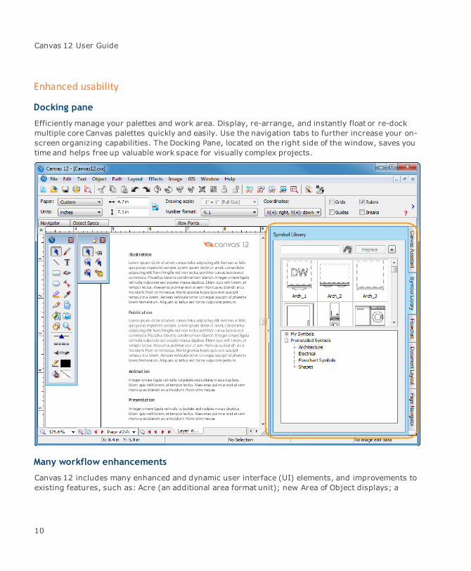
Enhanced usability
Docking pane
Efficiently manage your palettes and work area. Display, re-arrange, and instantly float or re-dockmultiple core Canvas palettes quickly and easily. Use the navigation tabs to further increase your on-screen organizing capabilities. The Docking Pane, located on the right side of the window, saves youtime and helps free up valuable work space for visually complex projects.
Many workflow enhancements
Canvas 12 includes many enhanced and dynamic user interface (UI) elements, and improvements toexisting features, such as: Acre (an additional area format unit); new Area of Object displays; a
10

Chapter 1: Introduction
Dimension Area global setting override; new Properties bar shortcuts for Number Format,Coordinates Format, and X,Y Arrows of Direction; a Set Default Attributes button in the Toolbar;Windows 7 support (with related UI enhancements); and increased Points Limits (crucial for GISdocuments).
About the documentation
Please take a few minutes to read the following information about the Canvas documentation. TheCanvas 12 Help/User Guide describes the commands, tools, and features of Canvas. Certain termsand abbreviations are used to describe procedures.
You’ll find tips for working efficiently and exploring creative possibilities.
Important items provide information to help you avoid problems.
Other items of note are highlighted with a note icon.
Keyboard keys
Standard names and abbreviations are used for keyboard keys; your keyboard might use differentlabels.
Key name Description
Alt The Alternate key, usually labeled “Alt”.
Ctrl The key labeled “Ctrl”.
Shift The key used to type uppercase characters.
Enter The key labeled “Enter”.
Choosing commands
When a procedure tells you to choose a command, the instruction is written:
Choose Edit | Paste.
This tells you to open the Edit menu and choose the Paste command. You can use a keyboard shortcutif the command has one.
11

Canvas 12 User Guide
Somemenu items open a submenu of related commands. When the documentation tells you tochoose a submenu command, the instruction is written:
ChooseObject | Arrange | Bring To Front.
This tells you to open the Object menu, choose Arrange to open the submenu, and then choose theBring To Front command.
Choosing commands in the context menu
You can choose commands from a menu that pops up wherever the pointer is in Canvas. Thecommands in the menu are based on what you are doing; therefore, the menu is called the contextmenu.
To choose a command from the context menu, press the secondary mouse button, usually the rightbutton.
Using modifier keys
For some actions, you need to press a keyboard key while you click or drag the mouse; e.g., to selectseveral objects, press the Shift key while you click each object. This can be written as Shift-click. Ifyou press the Ctrl key, for example, while you drag the mouse, the action can be written as Ctrl-drag.
Some instructions say to “right-click” an object. This means to click the object using the secondarybutton, usually the right button, on the mouse.
Contacting ACD Systems and updating Canvas
The following functions are available by opening the Help menu in Canvas.
Enter License Code
When you purchase Canvas, you receive a unique license number. When you install Canvas, you canenter the license number as part of the install process. However, if you have been using a free trialversion of Canvas, you can simply enter your license number by choosing Help | Enter License Code.
Product Support and Resources
ChooseHelp | Product Support and Resources to open the Canvas Product Support and Resourcespage on the ACDSee Web site, where you can find links to additional documentation and the
12
Chapter 1: Introduction
Knowledge Base.
Customer Support
ChooseHelp | Customer Support to open the Support page on the ACDSee Web site.
Product Registration
ChooseHelp | Product Registration to register Canvas.
Community
ChooseHelp | Community to open the ACDSee Community Web page on the ACDSee Web site, whereyou can find links to the ACDSee Product Forums, Blogs and Contests.
Related Products
ChooseHelp | Related Products to open the Products page of the ACDSee Web site.
Purchase Canvas
If you are using a free trial of Canvas and decide to purchase a license, choose Help | PurchaseCanvas. You can choose to purchase Canvas online or by phone.
Verify Document
If your Canvas document contains errors, you can verify your document to find out additionalinformation. Choose Help | Verify Document. Errors are listed in the dialog box. The Verify on Savecheck box is selected by default so that this check is completed every time you save your document.
Getting help with Canvas
If you need help while using Canvas, there are various utilities for your use.
Using the Help
Canvas includes a Help file to provide assistance right within the program.
13
Canvas 12 User Guide
For the latest information on Canvas, be sure to view any “Read Me” files included with theprogram.
To view Help in Canvas:
Do one of the following:
Press the F1 key.
ChooseHelp | Canvas 12 Help.
When you first open the Help, the Contents topic appears. You can also search for topics or use theIndex.
Showing the Startup screen
Select this command to open the Canvas Startup dialog box. You can create a new document, opendocuments, or access recent documents. You also have links to tutorials, online forums, knowledgebase articles, among others.
To open the Startup screen:
ChooseWindow | Show Startup.
Using the Canvas Assistant
Open by default, the Canvas Assistant dynamically displays information related to document setup,selected tools, and selected objects. Information is sorted according relevancy; i.e., specific, related,or general.
To open the Canvas Assistant:
ChooseHelp | Show Canvas Assistant.
To close the Canvas Assistant:
ChooseHelp | Hide Canvas Assistant.
Using the Dynamic Help
The Dynamic Help is a quick way to learn about the currently selected tool. In order to use theDynamic Help, the Properties bar must be visible.
14

Chapter 1: Introduction
To open the Dynamic Help:
Do one of the following:
ChooseHelp | Show Dynamic Help.
Click the Show Dynamic Help icon.
To close the Dynamic Help:
Do one of the following:
ChooseHelp | Hide Dynamic Help.
Click the Hide Dynamic Help icon.
15

Chapter 2: Documents and Setup
Canvas 12 User Guide
Running Canvas
This section explains how to start and end a Canvas work session. It also provides an overview of theCanvas interface and describes the following basic procedures:
Selecting tools from the Smart Toolbox™
Using and arranging palettes
Using the Properties bar
Using information displayed in the Status bar
Undoing, redoing, and repeating actions
Starting and exiting Canvas
To start Canvas, do one of the following:
Double-click the Canvas program icon if you’ve made a shortcut.
Double-click a Canvas document to start Canvas and open the document.
Double-click a Canvas template file to start Canvas and create a new document based on thetemplate.
ChooseCanvas from the Start | Programs menu.
To view start-up screen information:
When Canvas is running, choose Help | About Canvas. Do this when you want to check your serialnumber, version number, and other program information.
Checking optional software at start up
Canvas displays a message if it encounters a problem, such as missing system software components,as it starts. If a message appears, click OK to continue loading Canvas.
Canvas depends on some systemsoftware components for importing and exporting certain types offiles, managing colors, and working with some graphics formats. The Canvas installer places somesoftware called “Dynamic Link Libraries” on your system, if needed. If Canvas can’t find the requiredcomponent later, it’s possible the file was moved or disabled.
If you encounter a problem when starting Canvas, refer to the “Read Me” file, which includes themost up-to-date information on required software.
18

Chapter 2: Documents and Setup
Startup dialog box and new documents
Whenever you launch Canvas, the Startup dialog box opens. You can quickly create a new document,open documents, or access recent documents from this screen.
To disable the Startup dialog box:
Select the Don't Show Me This Screen Again check box.
To enable the Startup dialog box:
ChooseWindow | Show Startup.
Quitting Canvas
Choose File | Exit. If you try to quit without saving a document that has changed, Canvas asks if youwant to save it first.
Overview of the Canvas interface
Canvas has four types of documents: Illustration, Publication, Animation, and Presentation. Thesedocuments share some common elements, while some specialized controls apply to particulardocuments types.
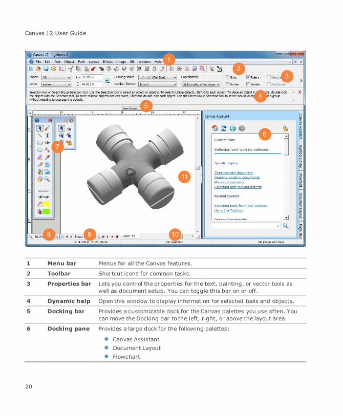
Canvas window
The Canvas interface contains eleven main components, providing you with a Layout area as the mainarea for working on your illustrations, and a variety of toolbars and docks with all the tools you need.Depending on your operating system and your Canvas customizations, your interface may lookdifferent than what you see in the image below.
You can customize the interface in several ways, such as by hiding the Toolbar, Properties bar,Docking bar, and Docking pane. You can also dock various palettes and customize the Toolbar. Eachdocument window has Zoom controls, Document controls, and scroll bars. All documents share theSmart Toolbox, Properties bar, and Status bar. You can switch between Canvas documents using theWindowmenu, or you can tile or stack windows to see more than one document at a time.
19
Canvas 12 User Guide
1 Menu bar Menus for all the Canvas features.
2 Toolbar Shortcut icons for common tasks.
3 Properties bar Lets you control the properties for the text, painting, or vector tools aswell as document setup. You can toggle this bar on or off.
4 Dynamic help Open this window to display information for selected tools and objects.
5 Docking bar Provides a customizable dock for the Canvas palettes you use often. Youcan move the Docking bar to the left, right, or above the layout area.
6 Docking pane Provides a large dock for the following palettes:
Canvas AssistantDocument LayoutFlowchart
20

Chapter 2: Documents and Setup
Page NavigatorSymbol Library
7 Toolbox Tool palettes snap out to the right. If you use a specific tool paletteregularly, lock the palette so it remains open while you use other tools.
8 Zoom controls Use these controls to zoom in and out of a document.
9 Documentcontrols
Add pages and move from one page or layer to another.
10 Status bar Displays the status and properties of the currently selected item.
11 Layout area Themain working area for creating illustrations, page layouts,presentations, and animations.
Layout area
The rectangle centered in the Canvas document window is the Layout area. The white space aroundthe Layout area is known as the pasteboard and is additional working spacewhere you can placeobjects before using them in an illustration. Objects on the pasteboard are saved with the document,but they are not printed.
The Layout area represents different things in the different Canvas document types.
Illustration: A page, called a “sheet,” with layers.
Publication: A single-sided page or two facing pages with layers.
Presentation: A “slide” with layers.
Animation: A frame of an animation. If you select “onion-skinning”, you can see objects onadjacent frames (see "All about onion skinning" on page 712).
You can change the color of the Layout area to represent the color of tinted paper.
To set the Layout area color:
1. Choose Layout | Document Setup.
2. Select a color from the Paper color popup palette.
Document navigation controls
A pop-up menu appears below the document window. Open this menu tomove through a document.
21
Canvas 12 User Guide
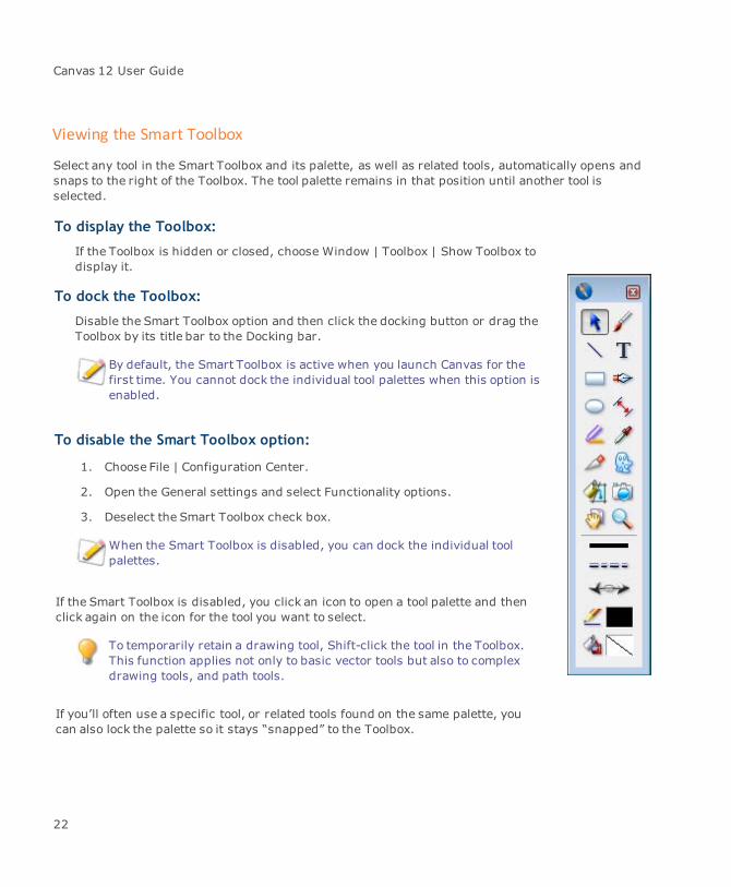
Viewing the Smart Toolbox
Select any tool in the Smart Toolbox and its palette, as well as related tools, automatically opens andsnaps to the right of the Toolbox. The tool palette remains in that position until another tool isselected.
To display the Toolbox:
If the Toolbox is hidden or closed, choose Window | Toolbox | Show Toolbox todisplay it.
To dock the Toolbox:
Disable the Smart Toolbox option and then click the docking button or drag theToolbox by its title bar to the Docking bar.
By default, the Smart Toolbox is active when you launch Canvas for thefirst time. You cannot dock the individual tool palettes when this option isenabled.
To disable the Smart Toolbox option:
1. Choose File | Configuration Center.
2. Open the General settings and select Functionality options.
3. Deselect the Smart Toolbox check box.
When the Smart Toolbox is disabled, you can dock the individual toolpalettes.
If the Smart Toolbox is disabled, you click an icon to open a tool palette and thenclick again on the icon for the tool you want to select.
To temporarily retain a drawing tool, Shift-click the tool in the Toolbox.This function applies not only to basic vector tools but also to complexdrawing tools, and path tools.
If you’ll often use a specific tool, or related tools found on the same palette, youcan also lock the palette so it stays “snapped” to the Toolbox.
22
Chapter 2: Documents and Setup
To lock a tool palette:
Click on the lock icon. When you select another tool, its palette snaps to the right of the lockedpalette.
When palettes are locked, you can relocate them to another part of the layout area. To do so, placethe pointer on the palette title bar and Shift-drag the palette from the Toolbox.
Also, if you Ctrl-drag the palette, you can move a group of locked palettes or a single locked paletteaway from the Toolbox.
To unlock a locked palette:
Click the lock icon.
Using the tools
In the Smart Toolbox, tools are represented by icons in two columns. The tools that aren’t displayedare available on tool palettes that snap to the Toolbox when opened.
To select a tool displayed in the Toolbox or tool palette:
Click the tool. The selected tool is shaded, like a recessed button.
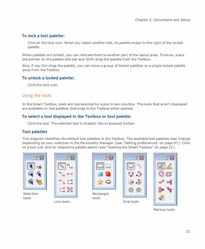
Tool palettes
This diagram identifies the default tool palettes in the Toolbox. The available tool palettes may changedepending on your selection in the Personality Manager (see "Setting preferences" on page 97). Clickon a tool icon and its respective palette opens (see "Viewing the Smart Toolbox" on page 22).
Selectiontools
Line tools
Rectangletools
Oval tools
Markup tools
23
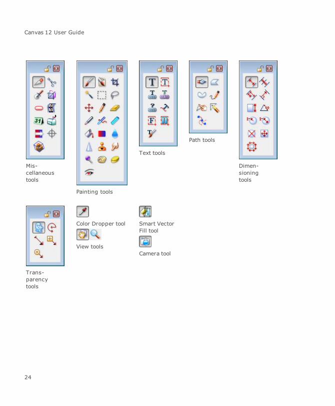
Canvas 12 User Guide
Mis-cellaneoustools
Painting tools
Text tools
Path tools
Dimen-sioningtools
Trans-parencytools
Color Dropper tool
View tools
Smart VectorFill tool
Camera tool
24

Chapter 2: Documents and Setup
To access tool palettes and tools via the Toolbox command:
If you are looking for a particular tool and are unsure where it is located in the Toolbox, chooseWindow | Toolbox to see the various tool groups.
To open a tool palette:
Click on the arrow icon and select Show Group. The tool palette automatically opens and snaps tothe right of the Toolbox.
To access an individual tool:
Click on the arrow icon and select the particular tool from the menu. The tool will be selected inthe Toolbox.
Using AutoSnap palettes
Canvas organizes tools, special effects, object attributes, and other functions in palettes. Palettescan remain open on screen, and they can be docked on the Docking bar. They can also attachtogether due to Canvas’ “snapping” technology for floating palettes, or rather AutoSnap™ palettes.
If you have two or more palettes open, you can position them so they attach together. Once attached,you can then move them around as a group.
To tear off a group of palettes:
Click on a palette’s title bar and hold down the Ctrl key while dragging the palette away. Anypalettes to the right of the selected palette move simultaneously.
To tear off a single palette:
Click on a palette’s title bar and hold down the Shift key while dragging the palette away. Only theselected palette moves.
To disable the AutoSnap palettes option:
1. Choose File | Configuration Center.
2. Open the General settings and select Functionality options.
3. Deselect the AutoSnap palettes check box.
Some palettes have an Apply button that you must click if you want to implement the current settings.A palette stays open until you click its close box or use a command to close it.
25

Canvas 12 User Guide
To roll up a palette so only its title bar is visible:
Click on theminus button on the palette title bar.
To dock a palette:
Click on the arrow button or drag the palette to the docking bar (see "Using the Docking bar" onpage 33 and "Using AutoSnap palettes" on page 25).
To arrange palettes:
ChooseWindow | Palettes | Clean Up Palettes. Canvas moves all open palettes except the ToolBoxand floating tool palettes to the upper-right corner of the document.
To close all palettes:
ChooseWindow | Palettes | Put Away Palettes. Canvas closes all open palettes, including theSmart Toolbox and floating tool palettes.
Palettes submenu
All Canvas palettes are listed in the Window | Palettes menu. To display a palette, choose the name ofthe palette in the submenu. If a palette is behind other palettes, it comes to the front. If a palette isdocked, the palette comes off the Docking bar and opens.
Tool palettes are listed in the Windows | Toolbox submenu.
Some palettes are also associated with commands in other menus; e.g., the Layout | DocumentLayout command opens the Document Layout palette. The Image | Show Channels/Hide Channelscommands open and close the Channels palette.
Presets palette icons in the Toolbox
You can access the Presets palette from the Strokes icon, Dash styles icon, Arrow styles icon, Pen Inkicon, and Fill Ink icon in the Toolbox. You can use these icons to select preset colors, dashes, arrows,and pen widths. To open the Presets palette, click on one of these icons to open the palette and thendrag the palette away from the Toolbox.
Pen strokes
Dash styles
Arrow styles
26
Chapter 2: Documents and Setup
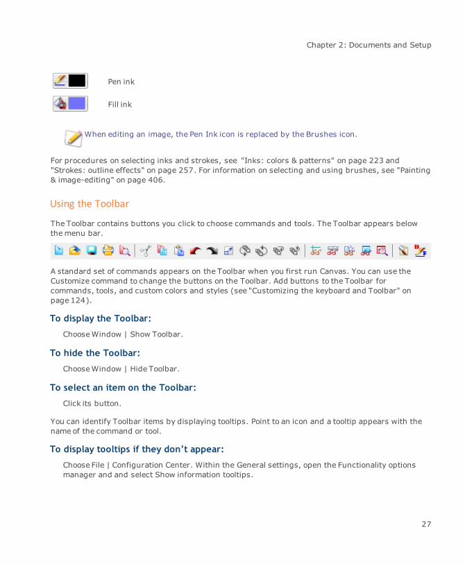
Pen ink
Fill ink
When editing an image, the Pen Ink icon is replaced by the Brushes icon.
For procedures on selecting inks and strokes, see "Inks: colors & patterns" on page 223 and"Strokes: outline effects" on page 257. For information on selecting and using brushes, see "Painting& image-editing" on page 406.
Using the Toolbar
The Toolbar contains buttons you click to choose commands and tools. The Toolbar appears belowthemenu bar.
A standard set of commands appears on the Toolbar when you first run Canvas. You can use theCustomize command to change the buttons on the Toolbar. Add buttons to the Toolbar forcommands, tools, and custom colors and styles (see "Customizing the keyboard and Toolbar" onpage 124).
To display the Toolbar:
ChooseWindow | Show Toolbar.
To hide the Toolbar:
ChooseWindow | Hide Toolbar.
To select an item on the Toolbar:
Click its button.
You can identify Toolbar items by displaying tooltips. Point to an icon and a tooltip appears with thename of the command or tool.
To display tooltips if they don’t appear:
Choose File | Configuration Center. Within the General settings, open the Functionality optionsmanager and and select Show information tooltips.
27

Canvas 12 User Guide
Using the Properties bar
Use the Properties bar to quickly modify the document setup, create some vector objects, modify toolsettings, apply a filter or effect to an object, cache objects, or apply text formatting.
If you hide the Properties bar, you won’t be able to display the Dynamic Help window.
To show the Properties bar:
ChooseWindow | Show Properties Bar.
To hide the Properties bar:
ChooseWindow | Hide Properties Bar.
Viewing and modifying document setup
When no items are selected in a document, the Properties bar displays document setup information.You can quickly and easily change the various document controls.
Document Setup options
Paper Select a standard paper size, or select Custom to enter a custom widthand height.
Units Select the unit of measure to use in the document.
Width and Height Displays the height and width of the document. If you change thesemeasurements, Paper is changed to Custom.
Click the Orientation icon to change the orientation between portrait andlandscape.
Drawing scale Select a drawing scale or set a custom scale for the document.
Number format Select a number format.
Coordinates Select a format for displaying coordinates.
Grids Displays a background grid. This can be helpful for laying out objects ina document.
Guides Displays any guides used in the document. To add a guide, drag thecursor from the vertical or horizontal ruler across the document.
28

Chapter 2: Documents and Setup
Rulers Displays the vertical and horizontal rulers.
Breaks Displays page breaks.
Margins Displays pagemargins.
Print area Displays the printable area.
Text boxes Displays text boxes.
Spelling errors Displays spelling errors.
Select Across layers Enables selections of objects across more than one layer.
Changing tool settings
When you select a tool, its settings automatically appear in the Properties bar. Use themenus, checkboxes, and scroll boxes to change the tool settings.
For example, if you select the Brush tool, the following settings appear in the Properties bar:
Modifying object properties
When an object is selected, the Properties bar automatically displays the object’s reference point,coordinates, height, width, rotation, and skew settings. You can also change the object’s opacity andtransfer mode.
Common object properties
X and Y Displays the X and Y coordinates.
For line objects, the Properties bar displays the X/Y coordinatesfor the start of the line and the end of the line, the length of theline, and the angle of the line.
Coordinate arrows Displays the default coordinate format for the document.
Reference point Displays the reference point for the object. This is the point on theselected object (or its bounding box) that position data is based on.Thereference point is also the fixed point used in an object’s transformation.
Width and Height Displays the height and width of the object.
Scale Click the down arrow to change between scaling the object
29
Canvas 12 User Guide
proportionally or not proportionally. Proportional scaling means that ifyou change the width of the object, the length is adjusted automaticallyso that the object retains the same proportions.
Transform Click the down arrow to transformed and untransformed dimensions.
Rotation Click the down arrow to change the direction or rotation. Enter a degreevalue in the Rotate field and press Enter. If you are rotating an image,you can also use the Image Hard Rotate options.
Skew Click the down arrow to change between horizontal and vertical skew.Enter a degree value in the Skew field and press Enter.
Opacity Move the opacity slider to the right or left depending on the desiredtransparency. For vector objects, you can also choose to apply the effecton the stroke and fill or only the fill by clicking on the Transparencybutton.
For text objects, you can change the opacity and transfer modeby using the Transparency palette (Window | Palettes |Transparency).
Transfer Select a Transfer mode. See "Using transfer modes" on page 685.
Transparency Select transparency on the object's stroke and fill, or just on the fill.
SpriteEffects Select an SpriteEffects effect. See "Using SpriteEffects" on page 650.
Make Lens Click this button tomake the object a lens. You can then applySpriteEffects to the lens. The effects appear on objects that are viewedthrough the lens. See "Creating a lens" on page 659.
SpriteEffects Palette Click to open the SpriteEffects palette. See "Using SpriteEffects" on page650.
Anti-alias Object Select this check box to smooth the edges of the object.
Scale byArea/Perimeter
Click to open the Scale By Area/Perimeter dialog box, where you canselect scale settings.
30

Chapter 2: Documents and Setup
To move an object:
Do one of the following:
Click on the object to select it, then drag it to the new position.
Click on the object to select it, then modify the X/Y coordinates and (optionally) thereference point in the Properties bar.
To copy an object and paste it in the same position on a different page, you can do so bycopying the object and then pressing Shift and choosing Edit | Paste.
To resize an object:
Do one of the following:
Click on the object to select it, then drag the object handles to resize it.
Click on the object to select it, then enter values in the width and height fields in theProperties bar.
To cache vector objects:
Caching can be used to speed up the display of complex objects, which is useful when a documentcontains complex objects that you do not need to edit often. When you cache an object, Canvas storesa low-resolution preview in memory. The preview can be displayed quickly when you move the objector change views. You can cache any type of object for faster display. To cache vector objects, groupthe objects first. The CacheObject check box only appears if the vector objects are grouped.
1. Group the selected vector objects.
2. Click the Cache Object check box.
3. Enter a value in the PPI field.
You can also group vector, image, and text objects and then cache the grouped object.
To align objects:
When you select more than one object the Align options are displayed on the Properties bar. You canchoose to align left edges, right edges, tops, bottoms, vertical or horizontal centers, or the centers ofthe objects.
31

Canvas 12 User Guide
1. Selectmore than one object.
2. Click one of the Align icons on the Properties bar.
Modifying images and paint objects
When an image or paint object is selected, the Properties bar automatically displays image and paintobject settings such as filters, adjust options, and export options.
Common image and paint object properties
Filters Select a filter to apply to the object. The last five used filters appear atthe top of the menu on the Properties bar. If you don’t click on the arrowicon to open the menu, the last filter used will be applied.
Adjust Select an Adjust filter to apply to the object.
Export Select an option to export the object to a different format.
Crop Select a crop and scale default size, or select Custom to define a specialcrop size. See "Changing image size" on page 448.
Res Enter a resolution in pixels per inch (PPI).
Preserve Data Click the check box to prevent resampling when the resolution ischanged.
Image Mode Select an image mode. See "Image modes for Canvas paint objects" onpage 435.
Cache Object Select the paint object and then click the Cache Object check box. Entera value in the PPI field.
When a cached paint object is placed into paint edit mode, itreturns to the original resolution.
Res Enter a resolution in pixels per inch (PPI).
Formatting text
When using various tools to create or select text objects, the text formatting options appear in theProperties bar. See "Formatting text with the Properties bar" on page 581.
You can also format text using the Type palette (Text | Type) and the Text menu settings.
32
Chapter 2: Documents and Setup
To cache text objects:
1. Group the selected text objects.
2. Click the Cache Object check box.
3. Enter a value in the PPI field.
Using the Docking bar
You can use the Docking bar to customize the Canvas interface. By default, the Docking bar isdisplayed near the top of the screen below the Properties bar when you launch Canvas for the firsttime.
To display the Docking bar:
ChooseWindow | Docking Bar | Show Docking Bar. When you display the Docking bar, thepalettes that were docked the last time it was displayed will remain locked.
To hide the Docking bar:
ChooseWindow | Docking Bar | Hide Docking Bar.
You can move the Docking bar from the top to the right and left sides of your workspace.
To move the Docking bar:
Click and hold the pointer on the Docking bar (not on a palette tab). Drag the Docking bar from itspresent position to either the top, left, or right.
The settings for the Docking bar are stored in the CVAppData.Set file.
Docking palettes
When you dock a palette, a tab with the palette’s name appears on the Docking bar. The tabs ofdocked palettes give you quick access to tools or features. Docked palettes also leave more screenspace.
You can dockmost Canvas palettes, including tool palettes (see "Tool palettes" on page 23). You candock other palettes from the Toolbox, including the Inks, Strokes, Transparency, and Brushespalettes. You can also dock command or effects palettes such as Align, Blend, Envelope, ObjectSpecs, and Type. Dialog boxes that require you to click OK or Cancel before continuing can’t bedocked.
33

Canvas 12 User Guide
Docked palette Floating palette
You can dock as many palettes as you want on the Docking bar, depending on the size of your screen(see "To adjust the size of tabs on the docking bar:" on page 35).
To dock a palette:
Do one of the following:
Drag a palette to the Docking bar and drop it when a tab outline appears.
Click the Docking button located in the upper right corner of the palette.
To dock a tool palette from the Toolbox:
First drag the palette away from the Toolbox so its title bar appears. Then, drag the tool paletteonto the Docking bar.
To change the position of a docked palette:
Drag the palette’s tab to another position on the Docking bar.
To remove a docked palette:
Drag the palette's tab away from the Docking bar.
To dock all open palettes:
ChooseWindow | Docking Bar | Dock All Palettes.
34
Chapter 2: Documents and Setup
To access the Docking bar commands, you can also right-click an empty area of the Dockingbar.
To dock palettes when closed:
ChooseWindow | Docking Bar | Dock Palettes When Closed.
To arrange docked palettes:
ChooseWindow | Docking Bar | Clean Up to arrange the tabs of docked palettes evenly on theDocking bar.
To arrange tabs by name:
ChooseWindow | Docking Bar | Clean Up By Name to arrange the tabs of docked palettes inalphabetical order.
To adjust the size of tabs on the docking bar:
1. ChooseWindow | Docking Bar | Set Tab Length.
2. In the dialog box, select one of the following:
Auto: Displays the full name of docked palettes.
Max Characters: Sets a specific tab size. Enter the number of characters to display. Asmaller number results in smaller tabs.
3. Click OK.
To make a selection from a docked palette:
Click the palette’s tab on the Docking bar. The palette pops open and you can click a tool or otheritem in the palette to select it. When you click in the document or the Toolbox, the palette closesagain. To close the palette without selecting anything, click anywhere outside the palette.
You can use docked palettes as if they are floating, with one exception: you cannot drag objects intodocked palettes.
Palettes that are docked in the Docking bar when you quit Canvas will be docked the nexttime you launch Canvas.
35

Canvas 12 User Guide
Using the Docking pane
You can use the Docking pane, located to the rightof the Layout Area, to dock the following palettes:
Canvas Assistant
Document Layout
Flowchart
Page Navigator
Symbol Library
To show or hide the Docking pane:
Click the Expand/Collapse button on the verticalsplitter bar.
If you remove all the palettes from theDocking pane and close them, you will notbe able to see the vertical splitter bar andthe Docking pane will be hidden. Toreopen the Docking pane, open one of thepalettes, such as the Canvas Assistant,and drag it to the Docking pane.
36

Chapter 2: Documents and Setup
Docking palettes
When you dock a palette, a tab with the palette’s name appears in the Docking pane stacked with theCanvas Assistant. The tabs of docked palettes give you quick access to tools or features and leavemore screen space for working on your document.
To dock a palette:
Do one of the following:
Drag a palette to the Docking pane and drop it when the palette window expands to fillthe pane.
Click the Docking button located in the upper right corner of the palette.
To remove a docked palette:
Click on the palette name at the top of the Docking pane and drag the palette away from the pane.
To view a docked palette:
Click the palette's tab to bring the palette forward.
To arrange docked palettes:
Click and drag a palette's tab tomove it to another position in the Docking pane.
Palettes that are docked in the Docking panewhen you quit Canvas will be docked the nexttime you launch Canvas.
Dynamic Help
In addition to the Canvas Help, which you access from the Help menu, Canvas also includes aDynamic Help window that is located just below the Properties bar. Dynamic Help displaysinformation and tips for selected tools and objects, even while you are performing tasks in edit mode.
The Properties bar must also be displayed if you want to open the Dynamic Help window.
To display the Dynamic Help window:
Do one of the following:
37
Canvas 12 User Guide
ChooseHelp | Show Dynamic Help.
Click on the Question Mark icon that appears on the right in the Properties bar when theDynamic Help window is closed.
To close the Dynamic Help window:
Do one of the following:
ChooseHelp | Hide Dynamic Help.
Click on the X icon on the right side of the open Dynamic Help window.
Using the Status bar
The Status bar is at the bottom of the Canvas window. The Status bar provides information aboutcommands, tools, objects, and program operations.
To set the number of information fields:
Point to the Status Bar, open the context menu, and choose from the Number of Fields submenu.
To add fields:
Point to the Status Bar, open the context menu, and choose a function in the Add to Right or Add toLeft submenu.
To remove a field:
Point to the field, open the context menu, and choose Remove.
New fields that you add to the Status Bar are blank until you assign a function to each field. If youreduce the number of fields, Canvas removes fields from the right end of the status bar.
To adjust the width of a field:
Drag its border right or left.
During certain actions, such as saving a document, Canvas displays a progress bar in the Status bar.
Assigning functions to fields
To assign a function to a field in the Status bar, right-click on a field to open the context menu, andchoose a function in the Show submenu.
38

Chapter 2: Documents and Setup
Hintline: The Hintline area displays tool names, tips, and status messages. When you movethe pointer over a tool icon or other item, the Message area shows the tool’s name andfunction. You can use this feature to take a tour of the Canvas tools and interface.
Mouse position: When you move the pointer, draw, resize, or rotate objects, Canvasdisplays the coordinates of the pointer.
Object Name & Number: Displays the current page number and layer number. Symbolsindicate layer options, including non-printing, locked, and color override. When an object isselected, the field displays the object’s number in the sequence of objects on the layer.
Object Type: Displays information about selections. When one object is selected, the fielddisplays the type of object selected. When multiple objects are selected, the field shows thenumber of objects selected. When you select an object group, the field displays “Group of nobjects,” with n as the number of objects.
Object Details: Displays various details about selected objects, such as the position ofpoints on the bounding box of a rectangle (as measured from the rulers’ zero point) and thenumber of points in a path object. For other objects, the field displays data such as thediameter of ovals and the angle of arcs.
Image Edit Data: Displays information about paint objects.
GIS Position: Displays the GIS position of the cursor.
Viewing documents
This section describes how you can adjust your view of a document. Viewing options in Canvas letyou:
Control when Canvas redraws objects.
Scroll to any area with the Hand tool or scroll bars.
Increase or decrease the view magnification.
Restore any view magnification and location.
Display wireframe and process-color views.
Controlling when Canvas refreshes the display
Canvas refreshes the display, which redraws all visible objects, when you scroll or changemagnification. When you work with complex images, you can interrupt the redraw to save time, thenrefresh the display when you’re ready.
39

Canvas 12 User Guide
To interrupt display redraw:
Press Esc during normal redraw.
To refresh the display:
Choose Layout | Display | Refresh. You can refresh the display after interrupting screen redraw,or when you want to refresh the display.
Scrolling documents
You can use scroll bars or the Hand tool to move to areas of a document that aren’t displayed in thedocument window.
Using scroll bars
Document scroll bars represent the full document area. The position of the scroll box within a scrollbar indicates the current view area.
To scroll using scroll bars:
Do one of the following:
Click one of the arrows tomove in the arrow direction.
Drag the scroll box toward the part of the document you want to see. For example, dragup to see more of the top.
Click the scroll bar to scroll one screen length toward the side of the scroll box that youclicked. For example, click to the right of the scroll box to move one screen to the right.
Using the Hand tool
Using the Hand tool to scroll a document is like sliding a piece of paper on a desktop.
To temporarily switch to the Hand tool while using another tool, press the Spacebar anddrag with the Hand pointer.
To scroll with the Hand tool:
1. Select the Hand tool. The pointer becomes a hand.
2. Drag to make the document follow the pointer. e.g. To move a document up so you can seethe bottom, drag toward the top of the screen.
40

Chapter 2: Documents and Setup
Changing the view magnification
You can change your view of a document by changing the view magnification. Zoom in to enlargeobjects or zoom out to see a larger area.
Zooming changes the view on screen, but doesn’t change the actual size of anything in thedocument.
You can zoomwith the Magnifying Glass tool, the Zoom controls, and Zoom commands. You can usemagnification levels from 0.0001 to 102400 percent. Normal magnification is 100 percent.
To use a command to zoom:
Choose Layout | Views | Zoom In or Zoom Out. Zoom In increases magnification to the next higherpreset level; Zoom Out decreases magnification to the next lower preset level.
To enter a zoom percentage:
1. Do one of the following:
Choose Layout | Views | Zoom.
Press Ctrl and the slash key (/).
2. Enter a zoompercentage from 0.0001 to 102400 press Enter.
Using zoom shortcuts
You can use keyboard shortcuts to zoom in and out.
To zoom in with any tool selected:
Press Ctrl+Spacebar and click or drag a box around an area; to zoom out, pressCtrl+Shift+Spacebar and click or drag a box around an area.
To zoom in directly:
Press Ctrl+Alt+Plus (+).
To zoom out:
Press Ctrl+Alt+Minus (-).
41
Canvas 12 User Guide
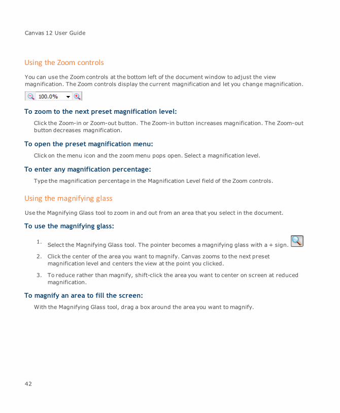
Using the Zoom controls
You can use the Zoom controls at the bottom left of the document window to adjust the viewmagnification. The Zoom controls display the current magnification and let you change magnification.
To zoom to the next preset magnification level:
Click the Zoom-in or Zoom-out button. The Zoom-in button increases magnification. The Zoom-outbutton decreases magnification.
To open the preset magnification menu:
Click on themenu icon and the zoommenu pops open. Select a magnification level.
To enter any magnification percentage:
Type the magnification percentage in the Magnification Level field of the Zoom controls.
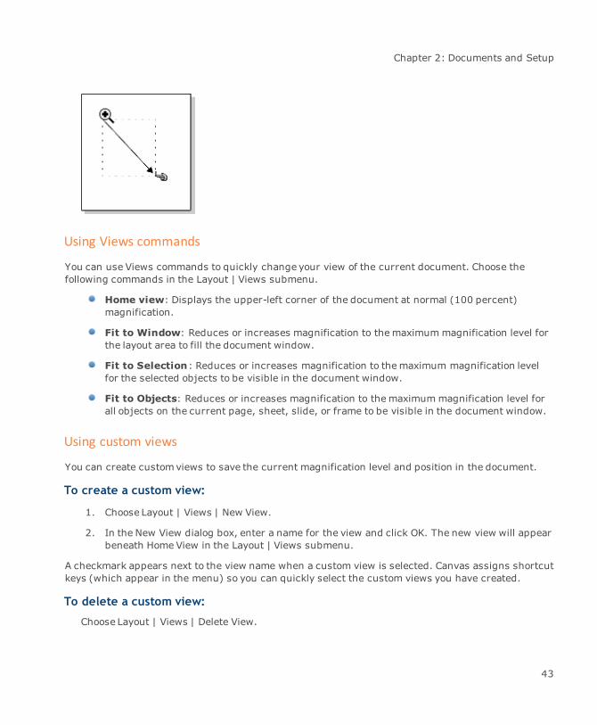
Using the magnifying glass
Use the Magnifying Glass tool to zoom in and out from an area that you select in the document.
To use the magnifying glass:
1. Select the Magnifying Glass tool. The pointer becomes a magnifying glass with a + sign.
2. Click the center of the area you want tomagnify. Canvas zooms to the next presetmagnification level and centers the view at the point you clicked.
3. To reduce rather than magnify, shift-click the area you want to center on screen at reducedmagnification.
To magnify an area to fill the screen:
With the Magnifying Glass tool, drag a box around the area you want tomagnify.
42
Chapter 2: Documents and Setup
Using Views commands
You can use Views commands to quickly change your view of the current document. Choose thefollowing commands in the Layout | Views submenu.
Home view: Displays the upper-left corner of the document at normal (100 percent)magnification.
Fit to Window: Reduces or increases magnification to themaximummagnification level forthe layout area to fill the document window.
Fit to Selection: Reduces or increases magnification to themaximum magnification levelfor the selected objects to be visible in the document window.
Fit to Objects: Reduces or increases magnification to themaximummagnification level forall objects on the current page, sheet, slide, or frame to be visible in the document window.
Using custom views
You can create customviews to save the current magnification level and position in the document.
To create a custom view:
1. Choose Layout | Views | New View.
2. In the New View dialog box, enter a name for the view and click OK. The new view will appearbeneath Home View in the Layout | Views submenu.
A checkmark appears next to the view name when a custom view is selected. Canvas assigns shortcutkeys (which appear in the menu) so you can quickly select the custom views you have created.
To delete a custom view:
Choose Layout | Views | Delete View.
43
Canvas 12 User Guide
If only one custom view exists, Canvas deletes it.
If more than one custom view appears in the Views submenu, the Delete Views dialog boxopens. Select a view and click OK. Canvas removes the selected view from the Viewssubmenu.
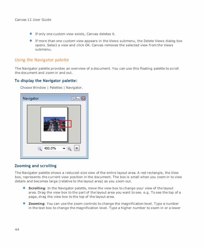
Using the Navigator palette
The Navigator palette provides an overview of a document. You can use this floating palette to scrollthe document and zoom in and out.
To display the Navigator palette:
ChooseWindow | Palettes | Navigator.
Zooming and scrolling
The Navigator palette shows a reduced-size view of the entire layout area. A red rectangle, the Viewbox, represents the current view position in the document. The box is small when you zoom in to viewdetails and becomes large (relative to the layout area) as you zoom out.
Scrolling: In the Navigator palette, move the view box to change your view of the layoutarea. Drag the view box to the part of the layout area you want to see. e.g. To see the top of apage, drag the view box to the top of the layout area.
Zooming: You can use the zoom controls to change the magnification level. Type a numberin the text box to change themagnification level. Type a higher number to zoom in or a lower
44

Chapter 2: Documents and Setup
number to zoom out. Normal magnification is 100%. Click the Zoom-in button on the right todouble the magnification level. Click the Zoom-out button on the left to reduce magnificationby half. The Zoom controls are at the bottomof the document window (see "Using the Zoomcontrols" on page 42).
To quickly change the view area, click within the Navigator palette. The view boxmoves towhere you click and the layout area shifts as well.
View options
You can choose view options from the Navigator palette menu. This menu contains the samecommands as the Layout | Views submenu. You can choose Home View, Zoom In, and Zoom Out,customviews that you have saved, and commands that make all objects or the entire layout areavisible in the window.
Using expressions for numeric values
You can type basic mathematical expressions to specify numeric values in Canvas dialog boxes andpalettes. You can use addition, subtraction, division, and multiplication operators in simpleexpressions; e.g., you can type a fractional value, such as 2/3, in place of a decimal value.
To type an expression:
To enter operators in expressions, type a plus sign (+) for addition; a minus sign (-) forsubtraction; a slash (/) for division; and an asterisk (*) for multiplication.
You can type parentheses to nest values and operators in expressions. Do not type an equal sign inan expression.
Canvas calculates the result of a mathematical expression when you press Tab or Enter, or click anApply button, or move to another value in a dialog box.
To modify a value:
1. To use an existing value in an expression, click after the number to place an insertion point.
2. Type the remainder of the expression; e.g., to make the width of an object 3 times larger,click after the existing value and type * 3, and then press Enter. To make the value one-thirdas large, type / 3.
By entering expressions after existing values in the Transform palette, you can move objectsincrementally; e.g., to move an object 3/4 inch to the right, type + 3/4 after the X value.
45
Canvas 12 User Guide
Specifying measurement units
In most dialog boxes, you can type abbreviations to specify measurement units. You can use thisfeature to override a document’s measurement units or the specific measurement units used in thesedialog boxes.
For example, when inches is a document’s unit of measurement, you can type 1 cm to specify 1centimeter. Canvas converts 1 cm and displays it as .3937 inches.
The following are the abbreviations you can type to specify a unit of measurement.
Abbreviation Unit of measure
in inches
ftf feet
y yards
mi miles
p picas
pt points
mm millimeters
m meters
km kilometers
cmc centimeters
To use an abbreviation for a measurement unit:
In a text box that accepts numerical values, type a value followed by the abbreviation for themeasurement unit.
Canvas converts the numerical value to themeasurement units you are using in the document whenyou press Tab or Enter, or click an Apply button, or click in another edit box.
You can even type a mathematical expression using more than one measurement unit; e.g., you cantype 1p+1cm.
Using context-sensitive menus
Canvas has context menus that you can pop up in the drawing area, giving you quick access tocommon commands. Themenus are context-sensitive; the available commands depend on the
46

Chapter 2: Documents and Setup
current operation.
Choose common editing commands, such as Cut, Copy and Paste, when an object is selected. Othercommands are available when an object is in edit mode; e.g., image-editing commands appear in thecontext menu when you edit a paint object. Path-editing commands appear when a vector object is inedit mode.
When no objects are selected, you can choose view commands such as Zoom In, ZoomOut, ShowRulers, and Show Guides. If the Clipboard contains objects or text, you can choose Paste. You canchooseUndo after performing an action that can be undone.
Using context menus
To apply a command to an object, select the object first. To use other commands, you do not need toselect an object before displaying the context menu.
Click the right mouse button. A context menu appears. Click a command in the menu to choose it.
When you are editing an object, you can point to a specific item to display commands for editing thatitem; e.g., if you point to an anchor point on a path, you can choose commands tomodify the anchorpoint in the context menu.
For information on specific commands that appear in the context menu, refer to the command namein the Index.
Document basics
Canvas documents are the containers for your work. You can create and save vector drawings, text,raster images and effects in Illustration, Publication, Presentation and Animation documents.
This section describes the basics of working with Canvas documents, including how to open, save,view, and print them.
Opening Canvas documents
Use the Open command to open Canvas documents. The general procedure is the same for openingCanvas documents and any other type of file that Canvas supports.
Documents opened recently are listed in the File menu.
47

Canvas 12 User Guide
To open a file:
1. Choose File | Open.
2. In the Open dialog box, select the file to open. Canvas displays a preview if the selecteddocument contains a preview.
3. Click Open.
To open a document you worked with recently:
Choose the document name from the list of recently opened documents in the File menu.
To start Canvas and open a document simultaneously:
Double-click a Canvas document icon in a folder or directory on your system. The program startsand the document opens.
Options for opening Canvas files
When you choose Open, a directory dialog box lets you select a file in the scroll list and see a preview.
You can select “Show All Files” to list all the files in a folder. This is different than Selecting “All” inthe File Format pop-up menu, which lists all files that Canvas can open.
If you need additional help working with files, folders, and directories, refer to your Windowsdocumentation.
You can open more than one document at a time in Canvas. When you open a document, Canvas loadsthe document into your system’s memory. You need to have enough memory available to hold thedocument’s contents. Documents that contain many complex objects or large high-resolution imagesrequire morememory than simple documents.
When you work with a document, changes you make to the document are not saved until you use theSave or Save As commands.
Substituting fonts when opening documents
If a document you open uses fonts that aren’t available on your system, Canvas displays a dialog boxbefore opening the document. Use the dialog box to review which fonts are required by the documentand to select substitute fonts, or you can let Canvas select substitutes.
To substitute fonts when opening a document:
1. Select a font listed under Original Font, or Shift-click to select multiple fonts. This columnlists fonts that are specified in the document but are not available.
48

Chapter 2: Documents and Setup
2. Choose a substitute font in the “With” pop-up menu. The name of the font appears in the listunder Substitute Font. Canvas displays the font name in its corresponding typeface so youcan preview the font substitution.
3. Select the check box to permanently replace the missing fonts with the fonts you choose inthis dialog box.
4. After you select substitutes for themissing fonts, click OK to open the document. To cancelthe changes, click Clear Changes to let Canvas choose a substitute and open the document.
Placing documents
Use the Place command to incorporate a document stored on disk into an open Canvas document.With the Place command, you can insert a Canvas document, an image, or a non-Canvas illustrationdocument; e.g., you can place a document containing your company logo within a document in whichyou are preparing a sales brochure.
The Place command lets you visually set the location and dimensions of the incorporated document.You can also control which layers, pages, or slides to place, and whether to place them on thecurrent layer, page, or slide, or on new ones, depending on the document type (Illustration,Publication, Animation, or Presentation).
If you place one Canvas document type (Illustration, Publication, Animation, or Presentation) intoanother document type, Canvas converts the placed pages, sheets, or slides to the format of thecurrent document. Document pages (and sheets or slides) can be added to the current document,along with their layers.
To place a file in an open Canvas document:
1. Choose File | Place.
2. In the Place dialog box, select the file that you want to place and then click Place.
3. If the file has more than one page or layer,in the Place Options dialog box, configure theoptions and then click OK.
4. Position the Place cursor in the open document where you want the top-left corner of theplaced file to be.
5. Click to place the file at its original size; Canvas inserts the upper-left corner of the file at thepoint you click.
To define the dimensions of the file you’re placing:
Drag to create a bounding box. Canvas inserts the file and scales it to fit the bounding box.
49

Canvas 12 User Guide
Place options
When you place a file with multiple pages or layers, the Place Options dialog box lets you specify howthe placed file should be added to the current document.
Place on currentlayer
Places the file’s objects on the current layer of the current page. Nopages or layers are created in the current document.
Show Place Cursor Select this option if you want to set the position or size of placed items onthe current page. After you click OK in the Place Options dialog box, aplace pointer appears. Click to set the position of the upper-left corner ofthe placed items, or drag to enclose an area in which you want theplaced items to fit.
Add new layer(s) tocurrent page
Places the document’s layers as new layers on the current page in thecurrent document.
Add new page(s) Places the document’s pages and layers as new pages and layers in thecurrent document.
Select Click to choose specific pages or layers to place. A dialog box lists theavailable items. Shift-click two items to select a range. Ctrl-click to selectmultiple items and toggle selected items. Click OK to close the dialogbox.
Saving Canvas documents
In Canvas you can choose to save an entire document, a selection, or a layer. You can also usecompression, or apply a password to protect a document.
Use one of the following:
Save: Updates a document file on disk and overwrites the previously saved version.
Save As: Lets you create a new file on disk from an open document, save documents astemplates, and use other graphics and text file formats.
When you use these commands, the default format for storing documents is the native Canvasformat.
50

Chapter 2: Documents and Setup
Saving files
To save a new Canvas document:
1. Choose File | Save As.
2. In the Save As dialog box, select a location to store the document and type a file name.
3. Click Save to store the document on disk.
To save changes to a document as you work:
Choose File | Save to update the document file on disk.
To save a document with a new name or in a new location:
Choose File | Save As. Enter a new name or select a new location in the directory dialog box, andthen click Save.
To avoid losing your work in the event of a power failure or system failure, use the Savecommand frequently as you work to store changes on disk. Also use the AutoSave featurelocated in the General settings in the Configuration Center (see "Setting preferences" onpage 97).
Saving selections and layers
In the Save As dialog box you can choose options to save selections or layers, and create previews.
Save EntireDocument
The default setting tells Canvas to save a complete document.
Save Selection Choose this option after you select the objects in the document that youwant to save as a new document. If you don’t select anything, this optionis not available.
Save Layer Select this option to save one or more layers in a new document. Then,click Layers to specify which layers to save. This option isn’t available ifthe document has only one layer.
51
Canvas 12 User Guide
Use Compression Check this box to reduce the size of files saved on disk.
Save Preview Select the this option to save a low resolution preview of the document.In applications that support previews, you can see a thumbnail image ofthe document before opening the file.
Applying password protection to Canvas documents
If you want to control who can open a Canvas document, you can protect the document with apassword.
To add a password to a document:
1. In the Save As dialog box, select the Encrypt file check box.
2. In the Password text box, enter a password.
3. In the Confirm text box, enter the same password again.
4. Click OK.
To change the password on a document:
1. In the Save As dialog box, click the Modify key button.
2. Enter and confirm the new password, and then click OK.
The encrypt option is only available when you save the document in the native Canvasformat. The PDF export has its own encryption method (see "Exporting as PDF" on page722).
Saving documents in multiple formats
You can save a document in more than one format by setting the Multiple Save Options.
To save a document in multiple formats:
1. Choose File | Save As.
2. In the Save As dialog box, select the Multiple Save check box.
52
Chapter 2: Documents and Setup
3. Click the Options button to select the formats you want to save.
Raster Formats /Non-raster Formats
Select the formats you want to save the file in.
Display Optionsdialog
Select this check box to display the Render Image or PDF Options dialogboxes so that you can select the settings for each format.
Save companion filesin subfolder
Select this check box to save the files in a subfolder. The Canvas imageis saved in the folder you specify in the Save As dialog box, and the otherfiles are saved in a subfolder with the same name as the Canvas image.
For example, if your Canvas image is named New_1.cvx, the subfoldercontaining the other files will also be named New_1.
If you do not select this check box, files are saved in the same folder asthe Canvas document.
Reset Click this button to reset the Multiple Save options to the factorydefaults.
Once you have saved a document in multiple formats, next time you save the document, it will besaved in all the formats you selected by default. If you want to choose different formats, click File |Save As, and click the Options button to change themultiple format options.
The Multiple Save check box is only available if you have selected CVX - Canvas as thedocument type in the Save As dialog box.
If you use the sameMultiple Save options regularly, you might want to create a CanvasTemplate TPL file to save your settings. When you create a new document using thetemplate file, your Multiple Save options are applied to the file.
Undoing, redoing, and repeating actions
You can easily correct mistakes, restore your work to an earlier state, and repeat commands usingthe Undo, Redo, and Again commands. The minimum and maximum number of times you can undochanges can be changed within the Configuration Center (see "Setting preferences" on page 97).
Canvas uses memory to store operations so they can be undone. The amount of memory depends onthe operation; e.g., undoing a filter applied to a 2 MB image requires significantly morememory thanreversing a change in type size.
53
Canvas 12 User Guide
Canvas allocates memory to ensure that you can undo the specified minimum number of actions.Canvas tries to set aside enough memory so you can undo the specified maximum number of actions.It uses this memory if it’s needed for other operations. Therefore, you should be able to undo thespecified minimum number of actions, but you might not be able to undo the specified maximumnumber of actions. The memory allocation ensures that you’ll have the most memory available inCanvas.
To cancel an action:
Do one of the following:
Choose Edit | Undo. You can choose Edit | Undo multiple times to undo canceled actionsin reverse order.
Press Ctrl+Z.
ChooseWindow | Palettes | Undos. In the palette, select an action that you want to undo.
Not all actions can be canceled with the Undo command. Actions that cannot be canceledinclude scrolling; closing or reverting to an earlier version of a document; selecting anddeselecting objects; deleting settings in palettes; and saving documents.
To restore actions you canceled using Undo:
Do one of the following:
Choose Edit | Redo. You can choose Edit | Redo multiple times to reinstate canceledactions in reverse order.
Press Ctrl+Shift+Z.
ChooseWindow | Palettes | Undos. In the palette, select an action that you want to redo.
To repeat a command or other action:
Choose Edit | Again.
When an action can be repeated, the Again command includes the name of the action; e.g., after yourotate an object, the Again command appears as “Rotate Again.”
Not all actions can be repeated. The Again command isn’t available if the previous actioncan’t be repeated.
54

Chapter 2: Documents and Setup
Reverting to the saved version of a document
The Revert command lets you discard changes made to a document since it was last saved. This isthe same as closing the document without saving changes, and then opening the original from disk.
Be certain that you want to discard all changes to a document before choosing the Revert command,because you cannot use the Undo command to restore your work after using the Revert command.
Keep in mind that you can use the Save As command to save a document with a new name. If you arenot certain that you want to discard changes to a document, use Save As to store a new version ondisk, then open the original document and compare the two.
To revert to a document’s saved version:
1. Choose File | Revert.
2. Confirm that you want to discard all changes.
Working with document windows
Each document you open appears in its own window. You can work with Canvas document windowsthe same as other windows. You can resize a window, expand it to fill the screen, and minimize or rollit up. Canvas provides commands to organize and select document windows when more than one isopen.
Selecting among open documents
When you open several documents at once, only one is active. TheWindow menu displays the namesof open Canvas documents. The name of the active document has a check mark.
To change the active window:
Do one of the following:
Choose the document’s name in the list at the bottom of theWindow menu.
Click a document’s window.
When you open more than one document, information in the Properties bar and Status bar, such asthe pointer’s location, applies to the active document. The same is true of floating palettes; palettesettings apply to the active document and they change when you switch documents.
55
Canvas 12 User Guide
Arranging windows
When you open more than one document window, you can stack or distribute them on screen so theyare easier to work with.
When Canvas arranges document windows, it resizes them if necessary so they fit within the mainprogram window or screen area.
To arrange windows in rows:
ChooseWindow | Tile Down.
To arrange windows in columns:
ChooseWindow | Tile Across.
To stack all windows:
ChooseWindow | Stack.
To arrange icons of minimized windows:
ChooseWindow | Arrange Icons.
Viewing and editing document properties
With the Properties command, you can view the properties of documents. You can view standard dataand add your own meta data to a document.
To view or edit properties:
1. Choose File | Properties to open the Document Properties dialog box. This dialog box containsthe following tabs: General, Statistics, Summary, and Custom.
2. Click a tab to display its options. Use the procedures later in this section to edit the options,where applicable, then click OK to implement the settings.
The document must be saved for some of its properties to be displayed.
Choosing a property
To view or customize a property, select a tab in the dialog box.
56
Chapter 2: Documents and Setup
The creation time can be different on the General and Statistics tabs. The Statistics tabsdisplays the date and time the document was created as a new document. The General tabdisplays the time it was first saved.
General: Describes general information about a saved document, such as type, location,size, attributes, when it was created, and when it was last modified.
Statistics: Displays when the document was created and when it was last modified. It alsoshows the last time the document was printed, the name of the person it was last saved by,the number of revisions, and the total editing time. The Statistics box contains informationabout the document and the objects contained in it.
Summary: Lets you customize information about the document. You can enter a title,subject, author, manager, and company. In the Category and Keyword boxes, you can typedata to categorize the document. The Comments box lets you type comments about thedocument.
Custom: Lets you add custom data to the document. You can choose names and data typesfor these entries, as described next.
To enter custom data:
1. Choose a name from the list for the data entry, or to create a new data name, type a name inthe Name text box.
2. Choose a data type from the Type menu. You can choose Text, Date, Number, or Yes or No.Then, depending on the type, enter a value in the Value box:
For Text, type any text value.
For Date, type a date from 1/1/1601 through 12/31/9999.
For Number, type a numeric value.
For Yes or No, click Yes or No.
3. Click Add to add the data entry to the Properties box.
To modify a data entry:
Click the entry in the Properties box, then change the type or value. You cannot change the nameof the entry. Click Modify to apply the change.
To delete a data entry:
Select the entry in the Properties box and then click Delete.
57
Canvas 12 User Guide
Printing documents
In Canvas, you can print to any printer set up on your computer or network, including PostScript andnon-PostScript printers.
For information on installing, setting up, and selecting a printer to use, refer to youroperating system documentation.
Printing a document
If your document uses a standard paper size and you want to print all the visible objects on the page,you can simply select a printer and print the document. However, Canvas also offers the flexibility toprintmultiple pages on a page, scale the page to fit the paper, print color separations, printregistration marks, and much more.
To print a document:
1. Choose File | Print.
2. In the Print dialog box, select a printer from the Name drop-down list in the Printer section.
3. On the General tab, select the print range and copy settings.
4. Select any other options you want to use from the Advanced, Separations, and Page setuptabs.
5. Click the Print button.
Print options
The Print dialog box contains four tabs: General, Advanced, Separations, and Page Setup.
General options
Printer Name: Select a printer from the drop-down list.
Properties: Click this button tomodify the properties in the printerdriver.
Print to file: Select this check box if you want to generate a postscriptfile rather than a printed document.
58
Chapter 2: Documents and Setup
Print range All pages: Prints all the pages in the document.
Pages: Prints the pages you specify.
Selection: Prints the currently selected object.
Odd-numbered pages only: Prints only the odd-numbered pages.
Even-numbered pages only: Prints only the even-numbered pages.
Copies Number of copies: Enter the number of copies you want to print.
Collate copies: Prints all pages of the document in order based on thenumber of copies requested, rather than printing all copies of page 1, allcopies of page 2, and so on.
Reverse order: Prints from the last page to the first, keeping pages inthe correct order if the printer stacks pages face-up in the output tray.
Print facing pages: If the document is formatted for spreads, Canvasprints facing pages on a single page. This option is available for printingPublications only.
Skip blank pages: Does not output document pages (or separationplates) that are completely blank.
Preview Click this button to see a preview of the printed page.
Some documents can be larger than the paper in your printer. To print the entire document,select the Tile option in the Page Setup dialog box. Canvas will “tile” (divide) the documentinto a series of pages matching the paper size of your printer.
Advanced options
Optimization Optimize image resolution to printer: Optimizes the resolution ofimages based on the printer capabilities.
Print proxied images at full resolution: Prints the high-resolutionimages that are linked to the proxies in the document. Canvas outputsthe images from the linked files on your computer. If you do not selectthis option, Canvas prints proxy images rather than the high-resolutionimages. This is faster and could be adequate when you are proofingother parts of a document.
Always send header: Sends a header to a Postscript printer.
59
Canvas 12 User Guide
Text always in front: Because of the way that Canvas rendersSpriteLayer effects, text that is not in front of all other objects can beoutput as rendered images rather than text. If you want to avoidrendering text for printing, select this option. Canvas will print the textobjects in front of all other objects.
If you have text that has special effects or is behind transparent objects,you should not select this option, so the text will be rendered and printedas it appears in the document.
Kanji fonts resident: Uses resident Kanji fonts on Postscript printerswhen you are printing Japanese text.
Transparency rendering: Choose an option in the TransparencyRendering menu to specify how transparency and SpriteEffects will berendered (converted to pixels for printing).
Smallest area: Renders the area inside the bounding box of alltransparent objects. This generates the least amount of additionaldata to print transparency effects. Do not choose this option if youare printing in color on non-PostScript printers and the documenthas vector and transparent objects that share the same color,because these printers will not match the colors precisely. In somecases, non-standard PostScript printers might produce a slightpixel shift between a transparent and non-transparent area of avector object. If this happens, select Complete Area.Complete area: Renders the area within the bounding boxes of alltransparent objects, as well as objects that are overlapped bytransparent objects (or intervening objects). This is the bestsetting to use when you print to a non-PostScript printer, such as aWindows GDI printer, to avoid color-matching problemsEntire document: Renders all objects in the document as one ormore images that are sent to the printer. This is equivalent toprocessing the document in an internal RIP (raster imageprocessor) in Canvas. This option produces the greatest amount ofimage data. However, this option can be useful if you experienceproblems producing accurate output of transparency or othereffects when you use a particular printer or printer driver.
60

Chapter 2: Documents and Setup
No transparency: Does not render any transparency effects inthe document. If you select this option, transparency (SpriteLayer)and image (SpriteEffects) effects will not be printed; transparentobjects will be printed as opaque objects.
The one exception to this rule involves vector objects that have atransparency Scope setting of Fill only when printing to aPostScript printer, because PostScript can print transparent fillinks in vector objects without rendering. For information on theScope setting, see "To set an object’s transparency scope:" onpage 671.
Select Don’t Render Transparent Objects if you need toquickly print a proof of a complex document. This allowsyou to check the positioning of objects without seeing thefinal transparency effects.
Rendered transparency effects are transmitted as imagedatawhen printing to PostScript printers.
61

Canvas 12 User Guide
Color mode: Choose an option to control color accuracy when using acolor printer. In general, when you print to a color printer, it’s best tochoose a color specification that matches the colors in the document you’reprinting; e.g., choose CMYK if your document contains CMYK colors only.
RGB: Outputs colors using RGB color specifications. A non-colorprinter will convert the color values to print as shades of gray.Black & White: Prints all colors as black or white.Colors As Grays: Canvas converts color values to shades of grayfor printing on any printer, including color printers.CIE L*a*b: Uses color calibration to try tomatch printed colors totheir appearance on screen. Keep in mind that many on-screenhues cannot be reproduced on paper with printing inks. Forexample, colors that look bright and saturated on screen, such ashot pink, cyan, and brilliant orange, will appear muted in printedmaterials.CMYK: Outputs colors using CMYK color specifications. A non-colorprinter will convert the color values to print as shades of gray.
62

Chapter 2: Documents and Setup
Image compression: Choose a format for output of image data to a Post-Script device or file. The format you choose affects the amount of datatransmitted and the size of a PostScript file. This setting can affect com-patibility with networks and PostScript printers.
ASCII: Outputs image data as plain text. This is the mostcompatible format, but it transmits (or saves in files) the largestamount of data.Binary: Outputs images as binary data, which might not becompatible with all printers and networks. Binary data is half thesize of ASCII data.Level 2 ASCII: Outputs images in an ASCII format that iscompatible with PostScript Level 2 devices. This produces files thatare approximately 20% smaller than regular ASCII PostScript files.RLE: Outputs images using Run Length Encoding compression.This format is compatible with PostScript Level 2 devices. This formof compression is most efficient when documents contain imagesthat have large areas of flat color.JPEG: Outputs images using JPEG compression. This format iscompatible with PostScript Level 2 devices. JPEG compressionrequires more system memory and more processing time at theprinter than other compression methods. However, this formatachieves the fastest printing results with continuous-tone(photographic) images and documents containing transparencyeffects.
By default, Canvas uses JPEG compression for printing images.This can reduce the amount of data sent to the printer. If anetwork print spooler reports errors with a JPEG data stream,select Images: ASCII or Level 2 ASCII and try printing again.The Images setting affects printing of images and renderedeffects only.
AdditionalInformation
Registration marks: Adds registration marks, used for alignment in col-ored printing.
Canvas file name: Includes the Canvas filename at the top of the page.
Crop marks: Includes crop marks, short vertical and horizontal linesthat indicate the border where an illustration or page can be trimmed.
Plate names: Includes plate names when you are printing separations.
63
Canvas 12 User Guide
Separations options
Print separations Select this check box if you want to print color separations.
Plates Halftone setting: Select the halftone setting. The default settings canbe used with most desktop printers.
Print spot colors as process: Prints any spot colors in the documentas process colors.
Trapping andoverprinting
Overprint black text: Overprints black text.
Overprint black objects: Overprints black objects.
Trap size: Enter the number of points to use for traps.
Page setup
Scale Fit to paper: Scales a document to fit within the page’s printable area.Remember that objects outside the layout area, will not be printed.
Center on paper: Centers a document on the printed page. If you’reprinting selected objects only, Canvas shifts the selected items to thecenter of the printed media. This option can be useful when you haveselected objects that you want to print in the center of the page, but theyare not centered in the document itself.
Tile: Prints a large document by dividing it among “tiles” of printerpages. Type an Overlap value in the text box so part of the documentrepeats at the edge of adjoining tiles; the overlap makes it easier toassemble the complete document after printing.
Thumbnails Print thumbnails: Select the number of pages to print per page. Thepreview area shows how your pages will be placed on the paper.
Previewing your printed document
The print preview reflects the current print settings and the page setup. In the preview, you can seewhich objects, layers, and pages will be printed. You can make sure the layout fits in the printablearea of the paper. If you choose the Tile option in the Page Setup tab or dialog box, the preview showsthe tiles as separate pages.
64
Chapter 2: Documents and Setup
To preview a printed document:
1. Do one of the following:
Choose File | Print Preview.
Choose File | Print, then click the Preview button.
2. Do one or more of the following to preview the document:
Click the zoom buttons to increase or decrease themagnification of the preview.
Click the arrow buttons to view other pages.
If you are previewing separations, click the plate buttons to view the plates that will beprinted for each page.
3. When you have finished previewing the document, do one of the following:
Click Print to send it to the current printer when you finish previewing a document andthe settings are correct.
Click Close to return to the document without printing.
Print Preview options
The Print Preview dialog box provides the Options, Separations, and Page setup tabs with the sameoptions as the Print dialog box (see "Print options" on page 58). You can use the Messages tab toview any printing related warnings or errors, such as warnings about spot colors.
Additional options appear at the bottom of the dialog box:
Show rasterized area Select this check box to see the objects that will be rendered when sentto the printer. This option depends on the selection in theTransparency rendering menu.
Showoverprint/choke/spread
These check boxes are related to the trapping technique that you canapply to objects via the Object Specs palette (Trap tab). If you haveapplied any technique, select the appropriate check box.
Normal display Select this radio button to switch to normal display if using wireframedisplay.
Wireframe display Select this radio button to switch to wireframemode.
65
Canvas 12 User Guide
Using Page Setup
If you always want to use the same settings when you print a particular document, you can save thesettings in the Page Setup dialog box. It’s a good idea to set these options when you create adocument so you can see page breaks correctly on the screen.
To set up pages for printing:
Choose File | Page Setup.
Page Setup options
Printer Select a printer from the drop-down list.
PPD If the printer you are using is a Postscript printer, also select a PPD(Postscript Printer Description).
Fit To Paper Scales a document to fit within the page’s printable area. Remember thatobjects outside the layout area, will not be printed.
Center On Paper Centers a document on the printed page. If you’re printing selectedobjects only, Canvas shifts the selected items to the center of the printedmedia. This option can be useful when you have selected objects thatyou want to print in the center of the page, but they are not centered inthe document itself.
Tile Prints a large document by dividing it among “tiles” of printer pages.Type an Overlap value in the text box so part of the document repeats atthe edge of adjoining tiles; the overlap makes it easier to assemble thecomplete document after printing.
Printer Properties Click this button to set up the printer properties in the printer's printdriver.
Canvas can obtain the page orientation from the printer properties. Select the correct pageorientation in the Page Setup dialog box, deselect any objects in your document, and then,in the Properties bar, select From Printer in the Paper menu.
Setting the print area
If you want to print only a selected area of a page, you can set the print area to define how much ofthe page is printed. This can be especially useful for large documents that don't fit easily on standard
66

Chapter 2: Documents and Setup
sizes of paper or complex documents where you want to focus on a single component. Once you haveset a print area, you can choose to toggle it on or off depending on whether you want to print just theprint area or the entire document.
To set the print area:
1. Choose File | Print Area | Set Print Area.
2. Use the Print Area cursor to draw a box around the area you want to print.
3. In the Print Area dialog box, check and adjust the Left, Top, Width, and Heightmeasurements as necessary.
4. Click the OK button.
An orange box appears in the document to indicate the printable area.
To toggle the print area on or off:
In the Properties bar, select or deselect the Print area check box.
When the print area is on, an orange box appears to indicate the printable area. When the printarea is off, the orange box disappears.
To remove the print area:
Choose File | Print Area | Clear Print Area.
Troubleshooting document printing
A few key factors affect how Canvas prints a document. Canvas decides which objects to print basedon the following:
Document boundary: Canvas does not print objects that are outside the layout area (therectangle that represents the document on screen). Objects that are partly inside and partlyoutside the layout area will be cropped in the printout.
Visible layers: Objects on layers that are not visible are not printed.
Printable layers: If a layer’s print option (in the Document Layout palette) is off, nothing onthe layer is printed.
Printable objects: If an object is made non-printable (in the Document Layout palette orthe Trap tab in Object Specs), the object will not print.
67

Canvas 12 User Guide
Printable area: If you have set a print area, then only the area within the print area isprinted. You can toggle the printable area by selecting its check box in the Properties bar.
Closing documents
When you close a document, Canvas removes the document window from the screen. Closing adocument doesn’t save it (Canvas will warn you if you try to close a document that has changed).
To close a Canvas document:
Choose File | Close. You can also click the Close button in the document’s title bar to close thedocument.
Document setup
When you create a new Canvas document, you select a document type. Then you specify thedocument size and other options.
This section explains how to create new documents and how to set up document rulers, drawingscales, guides, and alignment grids.
Creating new documents
In Canvas, you can create several different types of documents: Illustrations, Publications,Presentations, and Animations.
There are twoways to create a new document:
Startup dialog box: When you first start Canvas, you can create a new document from theStartup dialog box. The new document opens immediately. You can then use theConfiguration Center to change document attributes such as the document units anddrawing scale.
Inside Canvas: If you have Canvas open already, you can create a new document from theFile | New menu or by clicking the New Document icon. The New Document dialog box opensso that you can set the document attributes immediately.
To create a new document from the Startup dialog box:
In the Startup dialog box, click a document type.
If you don't see the Startup dialog box, choose Window | Show Startup.
68
Chapter 2: Documents and Setup
To create a new document from inside Canvas:
1. Do one of the following:
Choose File | New.
Click the New Document icon.
2. In the New Document dialog box, select the document type.
3. Select options for the new document.
4. Click OK.
New document options
The items that you define in this dialog box can bemodified via the Properties bar or Document Setupmanager (Layout | Document Setup).
Type of document Select a type of document. Depending on your choice, the dialog boxmay offer more or fewer options; i.e., Publication offers Marginsettings, rather than a Drawing scale, as well as a layout menu.
GIS Document If you are using Canvas +GIS, for ilustrations, you can select thischeck box to work with a GIS document. Once you click OK, the GISmanager opens so you can configure the GIS settings.
Drop-down list For a Publication document, select one of the following:
Full page: Creates a single page document.Facing pages: Creates a document with pages designed to beviewed side by side, like a spread in a magazine. A facing-pagesdocument has a master page with left and right pages.Tent card: Creates a document with two landscape pagesdesigned to use as a tent card.Greeting card: Creates a document with four pages designed foruse as a greeting card.
Choose documenttemplate
Use a template instead of choosing a document type and defining pagesize and orientation. Select templates for illustrations, publications, orpresentations (see "Using document templates" on page 71).
Paper Define the document size and paper unit. The maximum document sizeis 2000 miles x 2000 miles. Select preset sizes, or set the documentsize to the printer paper, or enter a custom size. To set up a customsize, choose Custom and enter the width and the height. Select thepaper unit from themenu.
69

Canvas 12 User Guide
To change the page orientation of the document, click the Portrait orLandscape button. This swaps the width and height values.
To change the paper color, select a color from the drop down.
Document units Choose the measurement units for the rulers (see "Setting up rulers"on page 74).
Select the Pixel mode check box to view graphics at 72 ppi before theyare rendered.
Drawing scale For an illustration, animation, or presentation, select one of the presetscale options or create a custom scale (see "Setting up rulers" on page74).
Margins For a publication, select the left, right, top, and bottom page margins.
Save as default Select this check box if you consistently work with the same documenttype and layout.
Choosing a document type
When you create a new document, you can select an Illustration, Publication, Presentation, orAnimation document.
Illustrations
Themost commonly-used format, Illustration documents are the basis for mostCanvas technical illustrations.
Illustration documents are general-purpose documents for all types of illustrationsand graphics. You can specify a custom document size, and the document can havemultiple pages (called sheets), with multiple layers on each sheet.
Publications
Publish documents using one of the standard paper sizes or a custom size. Specifyfull pages or facing pages, or choose one of the standard templates to createbrochures, flyers, labels, magazine pages, and more.
Publication documents are designed for publications printed with two-sided (facing)pages, although you can also create a Publication that has pages with single sides.You can usemaster pages to hold items that you want to appear throughout thepublication. You can also usemultiple layers on each page.
70

Chapter 2: Documents and Setup
Presentations
Presentations and slideshows provide a powerful way of displaying technical data.
Presentation documents are designed for on-screen slideshow presentations. You canusemultiple layers and a master slide to hold background elements. You can usemorethan a dozen transition effects, including wipe and dissolve, during slide showplayback.
Animations
Create simple animations from your technical illustrations.
An Animation document is designed for creating and editing web (GIF) animation files.An animation is composed of multiple frames, which are equivalent to the imageframes of film-based animations.
You can use onion-skinning in an Animation document. When you select onion-skinning, frames adjacent to the current frame appear in the background. This helpsset up object movement in an animation.
Using document templates
Templates are special Canvas documents that you can use as the basis for new documents. Whenyou select a template in the New dialog box, Canvas creates a new document containing the graphicsand text in the template and uses the template’s settings for layers, slides, pages, rulers, grids,guides, views, and default object attributes.
How is a template different than a regular Canvas document? When you choose a template in the Newdialog box, Canvas creates a new document based on the template, but doesn’t actually open thetemplate file. When you make changes to the new document and save it to disk, the changes don’taffect the template.
Canvas treats a template in a similar way when you open one by double-clicking its icon or using theOpen command. In either case, rather than open the actual template document, Canvas makes a newdocument based on the template’s document type and contents.
Templates, like regular Canvas documents, are various types: Illustration, Presentation, Publication,and Animation. In the New dialog box, the templates listed in the Use Template pop-up menu matchthe document type selected in the Type of Document area.
71
Canvas 12 User Guide
Setting up documents
After you create a document, you can use the Document Setup manager in the Configuration Centerto change the document type, measurement units, size, orientation, and other options (Layout |Document Setup).
The Document Setup manager present similar options for each type of document, with some specificoptions for a particular document type; e.g., in a Publication document, you can set facing pages andpagemargins. In a Presentation document, you can specify screen size.
To set up a document:
1. Choose Layout | Document Setup.
2. In the Document Setup manager, select the options you want and click OK.
Document Setup options
The following options are available in all document types, except as noted.
Document units
Choose an option in the Document Units pop-up menu. The unit you select will be used in the rulers.
Document size
You can set the document size tomatch the paper in your printer, or set up a document based on astandard or custom size. The controls for document size are labeled according to the type ofdocument (Illustration, Publication, and so on).
For illustrations larger than the current paper size, toggle the Breaks option in theProperties bar to see or hide page breaks. A line around the layout area indicates pageboundaries.
To use a standard size, choose an option from the pop-up menu. You can choose standard sizesbased on the document type.
From Printer: To base the dimensions of the layout area on your printer’s page size, chooseFrom Printer. The layout area will match the settings in the Page Setup dialog box. For moreinformation, see "Matching documents to printer pages" on page 74.
Custom: To specify custom dimensions, chooseCustom. Type the width in the first box andthe height in the second box.
72

Chapter 2: Documents and Setup
From Screen: In Presentations and Animations, you can base the size of the layout area onthemonitor’s size. To do this, choose FromScreen.
Orientation
To change the orientation of the document, click the button in the Orientation area. This swaps thewidth and height values of the document.
Margins
To set margin size for two-sided Publications, enter the Inside, Outside, Top, and Bottommargins inthe text boxes in the Margins area. For single-sided Publications, enter Right, Left, Top, and Bottommargins. Themargin is measured from the edge of the paper. Margins are not available in otherdocument types.
On screen, the document’s margins appear as a dashed line. The page boundary appears as a solidline around the edge of the layout area. Make sure the margins are not outside the page boundary(see "Matching documents to printer pages" on page 74).
Page layout
To specify multiple pages per sheet in a Publication, choose Tent Card or Greeting Card in the SheetLayout pop-up menu.
Facing pages
To create double-sided pages, select Facing Pages. When Facing Pages is on, the document has a leftand a right master page that you can apply to its left-hand and right-hand pages. This option isavailable in Publication documents only. Note that once you select Facing Pages for a Publication, itcannot be undone or changed to another document type.
Paper color
Lets you apply a solid color to the document layout area. The paper color is for display purposes onlyand does not print. To apply a paper color, select a color from the pop-up palette.
When objects are partially transparent, the paper color is visible through the objects.However, while the paper color is not visible through solid objects, in the real world, thecolors of objects will be affected by the color of the paper they are printed on; e.g., a yellowcircle printed on blue paper will appear green. This is not shown on screen in Canvas whenyou use the Paper Color option.
Canvas includes the paper color when it renders transparent objects, so the paper color affects therendered image the same as it does on screen in Canvas.
73
Canvas 12 User Guide
Matching documents to printer pages
Selecting “From Printer” in the Document Setup dialog box tells Canvas to use the page informationfrom the Page Setup dialog box. Canvas sets the orientation and dimensions In the Document Setupdialog box tomatch the selected page size.
When From Printer is selected and you change the page settings, Canvas changes the dimensions ofthe document to match. You can choose File | Page Setup to change the paper size, or its orientation;Canvas will update the dimensions of the document and you do not have to choose Layout | DocumentSetup.
When the document type is Illustration, and you select From Printer, the document size is equal tothe printable area or page boundary of the paper selected in the Page Setup dialog box. For all otherdocument types, the document size is equal to the paper size, rather than the page boundary.
If working with a large document, you can define a printable area (see "Troubleshootingdocument printing" on page 67). You can then toggle the Printable area option in theProperties bar.
On most printers, the page boundary is smaller than the paper size. Illustration documents are sizedto the page boundary, so illustrations will fit on the paper without being scaled. You should note thatthe page boundary on many printers is not centered exactly on the paper.
Canvas takes scaling into account when it sets the document dimensions and you specify a scalingfactor in the Page Setup dialog box; e.g., if you specify 50% scaling, the document size will be twicethe page size (or twice the page boundary size in an Illustration).
To see or hide the page boundary, you can toggle the Breaks option in the Properties bar.Canvas indicates the page boundary by a solid line around the border of the page.
When From Printer is selected, Canvas checks the Page Setup information each time you open thedocument. If necessary, it adjusts the document’s dimensions tomatch the page information.
Setting up rulers
You can set up rulers for a document using various units of measure and display the rulers at the topand left of the document window. Rulers help you track the pointer’s movement and let you createalignment guides in the layout area.
When you create a new document, you can also set the document’s drawing scale. Canvas bases therulers and all objectmeasurements on the drawing scale. Canvas uses scalemeasurements in theObject Specs palette, Properties bar, and in Dimension objects. You can also change these settingsfor the document in the Configuration Center (see "Setting preferences" on page 97).
74

Chapter 2: Documents and Setup
To display and hide rulers:
Toggle the Rulers check box in the Properties bar. The rulers must be displayed if you want tocreate alignment guides in the layout area.
To set up rulers:
1. Choose Layout | Rulers.
2. In the Ruler dialog box, select a unit of measurement from the Document unit drop-down list.This unit is displayed in the rulers, Object Specs palette, as well as Properties bar.
3. Define the drawing scale in the Document scale section. You can use the Pre-defined scalesor establish a custom scale; e.g., if you set the drawing scale to 1 inch = 1 foot, and draw aline 1 inch long on screen, Canvas displays the line’s length as 1 foot.
4. Choose the formats for the numbers, angles, and coordinates. For the number format, youcan choose from no decimals to six decimals, or even use exponentials or fractions.
5. Click OK.
Adding and modifying units of measurement
You can further customize the rulers by adding units of measurements or modifying the definitions ofexisting ones.
The Add unit feature is a document-based function; i.e., any units that you add pertain tothat particular document and will not be available when you open another document.
To access these functions, choose File | Configuration Center to open the Configuration Center. Underthe Measurements manager, click on Define unit.
To delete a unit of measurement:
Select the unit in the menu and click the Remove button.
To add a unit of measurement:
1. Click the Add button.
2. In the Add Unit dialog box, enter the Unit name, Plural name, as well as Abbreviation.
3. Set up the new unit’s drawing scale by using the Length and Minor divisions controls.
4. Click OK to add the unit to the menu.
75
Canvas 12 User Guide
To modify a unit of measurement:
You cannot change the unit name or plural name.
1. Click the Modify button.
2. In the Modify Unit dialog box, change the unit’s Abbreviation, if needed.
3. Set up the unit’s new drawing scale by using the Size and Subdivisions controls.
4. Click OK to close the dialog box.
Assigning X/Y position to points
If you are trying to recreate a portion of an illustration, you may need to move the zero points orassign an X/Y position to a specific point in the drawing area.
To assign a position:
1. Place the cursor over the intersection of the rulers in the upper left corner. The cursorchanges to a double-sided arrowhead.
2. Click and drag the cursor to the location in the Canvas work areawhere you want to assignthe X/Y position.
3. In the Assign Position dialog box, enter the X/Y coordinates in the fields or use the scrollboxes.
4. Click OK. The Rulers shift to reflect the assigned position.
To change rulers:
You can change the current document unit and drawing scale by using the Units and DrawingScalemenus in the Properties bar. To view these items, deselect all objects.
To use ‘tear-off’ rulers:
When rulers are displayed, you can move a copy of a ruler into the layout area tomeasure specificareas of an illustration. When you tear off a ruler and move it, Canvas takes a snapshot of the rulerand pastes it into the document as a paint object. A tear-off ruler isn’t active like the rulersdisplayed at the window edges.
To place a tear-off ruler in a document:
Point to the ruler you want to tear off, press Alt and drag a copy of the ruler into the document.
76

Chapter 2: Documents and Setup
Document scale methods
Canvas features scaling options that will certainly be useful to those whowork with large documents,such as shape files. When selecting certain options, the Scale Options dialog box opens. Whenselecting the Set Document Scale command, the Define Document Scale dialog box opens.
To view these scaling methods:
Choose Layout | Document Scale.
When you use either method in a geo-referenced document, the GIS referencing isadjusted.
Scale options
The Document Scale dialog box appears when you choose Crop And Fit To Sheet, Fit All Objects ToSheet, or Fit Selection To Sheet. If you do not wish to scale a certain object, select its respectivecheck box.
You also have the option of applying this command to objects on hidden layers.
If you leave a check box deselected, the corresponding objects are scaled once you click OK.
What is a point object?
A point object represents a geometric shape that consists of a single point. You can select vectorobjects in your document and switch their status to point object.
If you were creating a floor plan and had created small vector objects that represent items such astables, chairs, lamps, etc., you would probably not want them to change size if you decide to changethe scale. Therefore, you could select them and assign them the point object status.
To switch to point object status:
1. Select all objects to be changed.
2. ChooseGIS | Tag selection as | Treat as point object to assign the point object status. Whenyou select an object that has point object status, Point Object is indicated in the Status bar.
77

Canvas 12 User Guide
To remove the point object status:
1. Select all point objects to be changed.
2. ChooseGIS | Tag selection as | Treat as regular object. The object returns to its previousstatus; i.e., vector object.
Crop and fit to sheet
When applied, a hard crop is performed and the resulting objects is scaled proportionally. Thiscommand can be used on both image and vector objects.
The document scale and origin are adjusted so that object position and dimensions arepreserved. In a GIS document, the geo-referencing information is also preserved.
To crop and fit to sheet:
Drag the crosshair diagonally across the objects to form a cropping rectangle. Place the cursorwithin the cropping rectangle and click to complete the crop.
You can move or resize the cropping rectangle, if necessary.
Fit all objects to sheet
When applied all objects within the document will be scaled proportionally. The objects are containedwithin the bounds of the top and bottom of the document.
If the document contains 5000+ objects, a warning dialog box appears. All previousoperations, including Fit All Objects To Sheet, cannot be undone.
Fit selection to sheet
When applied, the selected objects will be scaled proportionally. The objects are contained within thebounds of the top and bottom of the document.
Set document scale
You can use this command to customize a document’s drawing scale, which is useful if you areworking with objects that have known measurements.
78
Chapter 2: Documents and Setup
To use the Set Document Scale command:
1. Choose Layout | Document Scale | Set Document Scale. The Define Document Scale dialogbox opens. The cursor changes to a crosshair.
2. Click the crosshair once to establish the scaling start point.
3. Click a final time to set the scaling end point. The resulting distance is indicated in the Pagedistance field. The Define Document Scale dialog box opens. The first value is the distancethat you measured. The unit of measurement corresponds to the ruler’s unit ofmeasurement.
4. Enter the custom scale in the bottom field and select the unit of measurement from themenu.
5. Click OK.
Scale bar
The Scale Bar command draws a labeled scale bar. Scale bars are included in a variety of illustrationsand images.
The labels on the scale bar are created using the default text settings. Although you canchange the text appearance afterwards, you should establish the text settings beforemaking the scale bar.
To open the Create Scale Bar dialog box:
ChooseObject | Options | Create Scale Bar.
Create Scale Bar dialog box
The current document scale is indicated at the top of the dialog box.
Units Select a primary unit from the menu. The primary unit is displayedabove the scale bar.
Secondary Units If necessary, select a secondary unit. The secondary unit is displayedbelow the scale bar.
Major Division Length Enter the desired length for the scale bar.
Major Division Count Enter the number of major divisions for the primary unit.
Minor Division Count Select the check box and enter the number of secondary divisions forthe primary unit.
79
Canvas 12 User Guide
Style Select a option for the scale bar’s appearance.
Font Select a font for the scale bar. Select Title to indicate the currentdocument scale above the scale bar. If Title is enabled, you can controlthe point size. Use the Text control to change the point size for thescale bar labels.
Using the alignment grid
You can display a grid of vertical and horizontal lines to aid in positioning objects in a document. Youcan also turn on the snap-to-grid feature tomake Canvas snap objects into alignment with the gridwhen you drag near a grid line.
When snap-to-grid is active, the pointer movements snap to the grid according to the settings in theGrids manager.
To display grids:
Do one of the following:
Select the Grids check box in the Properties bar.
Choose Layout | Display | Show Grids.
To turn off grids:
Do one of the following:
Deselect the Grids check box in the Properties bar.
Choose Layout | Display | Hide Grids.
To turn on snap-to-grid:
Choose Layout | Snap To | Grid. Choose the command again to turn off snap-to-grid.
To temporarily override the grid constraint:
Press Tab as you create, resize, or move objects.
To set up the alignment grid:
1. Choose Layout | Grids.
2. In the Grids manager, enter a value in the Line Distance X: Units text box.
80

Chapter 2: Documents and Setup
3. Enter a value in the Line Distance Y: Units text box.
4. Enter a value in the Snap Factor X: Fields text box.
5. Enter a value in the Snap Factor Y: Fields text box.
You can enter decimal or fractional values; Canvas converts fractional values to decimalvalues; e.g., if the Line Distance is 1 inch, a Snap Factor of 1/2 Fields sets snap points every1/2 inch.
6. Select Snap to X and Snap to Y tomake objects snap to the snap points on both sets of gridlines.
7. Click OK to implement the grid settings.
Using alignment guides
You can create alignment guides and alignment objects. Other objects can “snap” to alignmentguides and objects. Alignment guides are horizontal and vertical lines you drag into a document fromthe rulers. When you create alignment guides, Canvas places the guides on a guide layer. You canalso create guide objects from any vector objects. Guide objects are placed on a guide layer; e.g., ifyou draw a rectangle on a guide layer, objects can snap to the sides of the rectangle. Alignmentguides and objects normally do not print, because the guide layers are set to be non-printing.
To show or hide guides:
Do one of the following:
Toggle the Guides check box in the Properties bar. Deselect any objects to view thecheck box.
Choose Layout | Display | Show Guides or Layout | Display | Hide Guides.
To activate snapping to guides:
Choose Layout | Snap To | Guides. When the snap-to feature is active, objects you move will snapto alignment guides and objects on guide layers.
To set up alignment guides:
1. Display the rulers by selecting the Rulers check box in the Properties bar.
2. Point to either ruler and drag a guide into the document area.
To remove a guide:
Drag the guide back to its ruler.
81

Canvas 12 User Guide
To move objects touching an alignment guide:
Press Ctrl as you drag an alignment guide. This method does not apply to alignment objects on aguide layer.
To set up alignment objects:
1. Select one or more vector objects.
2. ChooseObject | Arrange | Send to Guide Layer. Canvas moves the selected objects to theguide layer on the current page.
The ink and stroke attributes of guide objects are overridden by default on guide layers. Guideobjects appear with a blue pen ink, a 1-point stroke, and no fill ink.
If you move an alignment object off a guide layer, its original attributes reappear.
You can edit guide objects without moving them off a guide layer; e.g., you can select a guide object,drag its selection handles, use freeformmode to transform it, and use edit mode to reshape it.
To position guides numerically:
After you place a guide line in a document, you can set its position numerically.
1. Double-click an alignment guide to open the Guides dialog box.
2. Select Horizontal or Vertical to set the guide’s orientation.
3. Enter the Guide position in the text box. Positive values go down and to the right from thezero point. Negative values go up and to the left.
4. Click OK.
When you enter a value for the position of a guide, you can use the current measurement units, orenter a unit abbreviation; e.g., to place a vertical guide 3 inches to the right of the zero point, type“3in” (without quotes) if the current units are not inches. To set a horizontal guide 2 picas above thezero point, type “-2p”.
Document layout
You can usemultiple pages and layers in any document as well as set up master pages, sharedlayers, guide layers, and grid layers. Layout options also include slide transitions and timing for GIFanimations (see "Creating slide shows" on page 728 and "Working with animated GIFs" on page712).
82
Chapter 2: Documents and Setup
This section describes document layout options and procedures, including how to add, delete, andarrange pages and layers, and use the Document Layout palette.
About document pages and layers
Pages, layers, and master pages are a common element of all types of Canvas documents.
Pages
All Canvas documents can contain multiple pages. Here, “pages” is used as a general term forelements that make up a document.
Publications can have single or facing pages.
Illustrations have pages, called “sheets,” which are single-sided.
Presentations have pages, called “slides,” which can be displayed in sequence as “slideshows.”
Animations have pages, called “frames,” which form animation sequences for animated GIFfiles.
In the Document Layout palette, pages are at the top level of the layout hierarchy, followed by layers,groups, and objects.
The Layout area in Canvas represents a document page. Page and layer controls are located at thebottomof the screen. The current page is shown in the Pagemenu and the Page Navigator palette.
Layers
A layer is a transparent level that objects are placed on. On a page you might have one or morelayers. You can use layers to organize similar objects together. For example, you might use one layerfor text and another layer for objects. By default, when you place or draw objects on a page, they areplaced on a single layer. Layers can help you work efficiently. You can organize objects on layers,and you can display, print, and save layers individually.
In the Document Layout palette, a page’s layers are listed after the page name. Objects are listedafter the layer they are on. A new page has one layer (Layer #1). You can add layers to any page,including master pages.
You can save time by sharing layers in a document. A shared layer is similar to a master page. Aswith a master page, objects on a shared layer appear on every pagewhere the shared layer isapplied. You can update multiple pages by editing a shared layer.
83

Canvas 12 User Guide
Master pages
Master pages are available in Publication documents. Similar elements called “master slides” areavailable in Presentation documents, and “master frames” are available in Animation documents.
Master pages are pages used as a master or background for other pages. The objects on themasterpage can appear on every page in a document. For example, if you wanted to add a logo to every pagein your document, you could create a master page with the logo, and then apply the master page toyour other pages. If the logo is changed or updated, you can simply update the master page, ratherthan having to update every page of your document.
In the Document Layout palette, themaster page is listed under each pagewhere the master page isvisible. Themain master page is at the top of the list. As with other pages, you can use one or morelayers on a master page. By selectively hiding layers on the master page, you can control the masterpage appearance throughout a document or on selected pages. The master page at the top of thelayout list can be locked.
84
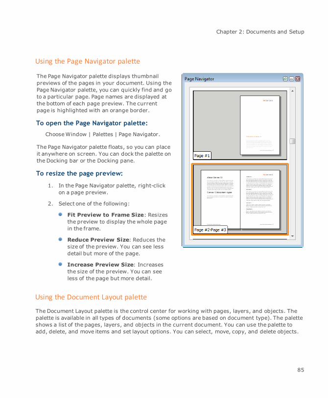
Chapter 2: Documents and Setup
Using the Page Navigator palette
The Page Navigator palette displays thumbnailpreviews of the pages in your document. Using thePage Navigator palette, you can quickly find and goto a particular page. Page names are displayed atthe bottom of each page preview. The currentpage is highlighted with an orange border.
To open the Page Navigator palette:
ChooseWindow | Palettes | Page Navigator.
The Page Navigator palette floats, so you can placeit anywhere on screen. You can dock the palette onthe Docking bar or the Docking pane.
To resize the page preview:
1. In the Page Navigator palette, right-clickon a page preview.
2. Select one of the following:
Fit Preview to Frame Size: Resizesthe preview to display the whole pagein the frame.
Reduce Preview Size: Reduces thesize of the preview. You can see lessdetail but more of the page.
Increase Preview Size: Increasesthe size of the preview. You can seeless of the page but more detail.
Using the Document Layout palette
The Document Layout palette is the control center for working with pages, layers, and objects. Thepalette is available in all types of documents (some options are based on document type). The paletteshows a list of the pages, layers, and objects in the current document. You can use the palette toadd, delete, and move items and set layout options. You can select, move, copy, and delete objects.
85
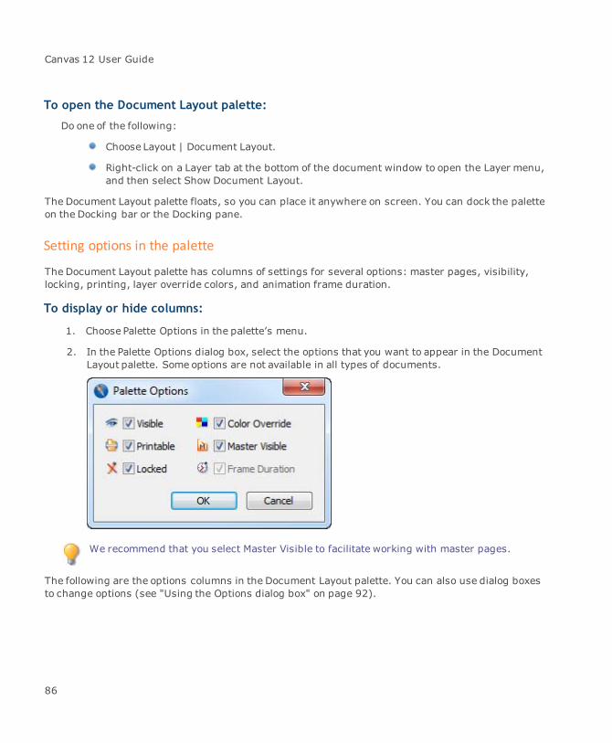
Canvas 12 User Guide
To open the Document Layout palette:
Do one of the following:
Choose Layout | Document Layout.
Right-click on a Layer tab at the bottom of the document window to open the Layer menu,and then select Show Document Layout.
The Document Layout palette floats, so you can place it anywhere on screen. You can dock the paletteon the Docking bar or the Docking pane.
Setting options in the palette
The Document Layout palette has columns of settings for several options: master pages, visibility,locking, printing, layer override colors, and animation frame duration.
To display or hide columns:
1. Choose Palette Options in the palette’s menu.
2. In the Palette Options dialog box, select the options that you want to appear in the DocumentLayout palette. Some options are not available in all types of documents.
We recommend that you select Master Visible to facilitate working with master pages.
The following are the options columns in the Document Layout palette. You can also use dialog boxesto change options (see "Using the Options dialog box" on page 92).
86
Chapter 2: Documents and Setup
Palette options
Visible Click to show or hide a page, layer, or object. Hiding a page hides all itslayers (unless one is the current layer). When something is hidden, ahollow circle appears in the Visible column. If the object is visible, ablue-filled circle appears in the column.
Printable A bullet indicates an item will print. When no bullet appears, the itemwill not print. If you change this option on a page, the setting is appliedto all the page’s layers.
Locked Click to lock or unlock a page, layer, or object to prevent or allowchanges. A bullet indicates an item is locked and its contents can’t beselected, moved, edited, or deleted. Grid layers are always locked. Apadlock icon indicates an item is also password-protected.
Color Override Click in the column to apply an override color to a layer. A square withthe override color appears in the column. To select an override color inthe Layer Options dialog box, double-click the layer name. To hide alayer’s override color, click in the column to remove the color square.
Master Visible Click to show or hide the master page on a document page. If themasterpage is hidden, a hollow circle with gray outline appears in the column.When the master page is visible, the hollow circle has a blue outline.Master pages are not available in Illustration documents.
You can hidemaster page layers using the Visible option. Hiding allmaster page layers is the same as hiding themaster page.
Frame Duration In Animation documents, this column shows the duration of a frame inhundredths of a second. To change the frame’s duration, double-clickthe frame name, change the duration value in the Frame Options dialogbox, and click OK.
Using the layout list
You can use the list in the Document Layout palette to display and select pages, layers, and objects.You can expand the list to display more detail, or collapse it to display fewer items.
Items in a document are listed in a tree format in the Document Layout palette. The layout list is ahierarchy. Pages are at the top level, followed by layers, then group objects, then individual objects.Each level is indented to the right from the level above. The master page and its layers are listed aftera page’s regular layers.
87
Canvas 12 User Guide
The name of the selected item in the list is shaded. The active layer name is bold. Names of masterlayers, shared layers and objects on shared layers are italic.
To expand or collapse items in the list:
Do one of the following:
Click a plus to expand the list; click a minus to collapse it.
Ctrl-click an item to toggle the state of its sub-items. If you Ctrl-click a page, itsexpanded layers will collapse, and its collapsed layers will expand.
Choose Expand All or Collapse All in the palette’s menu. The current level (pages, layers,or object groups) will expand or collapse. You can also Alt-click in the list to do the samething.
Selecting items
You can select one or more items at once in the layout list. The name of a selected item is shaded.
Selecting a page makes it the current page. The last current layer of the current page will bethe current layer.
Selecting a layer makes it the current layer.
Selecting an object selects the object in the document.
Selecting any item that is not visible makes the item visible.
To select one item:
Click the name of the item in the list.
To select multiple items:
Click the first item and Shift-click the last item. This selects a continuous range of pages, layers,or objects. To select or deselect individual items in a selection, press Ctrl-click each item.
Searching for items
Canvas can find items in the layout list by searching their names. This means you can go to pagesand layers, and select objects in a document, by typing some or all of the text in an item’s name inthe search box.
88

Chapter 2: Documents and Setup
To select an item in the list:
Type the text to find in the search box in the Document Layout palette.
When you stop or press Enter, Canvas searches the list from the current page. The searchincludes only items that are visible in the list (not collapsed pages).
You can type text in upper or lower-case. If an object in the list is named “Rectangle Fill 0c 67m 45y23k” and you type “23K” Canvas will select the object. Default object names are object type and inkvalues. Default page and layer names are item type and sequence number. Double-click on a layer,page, and object in the layout list to assign names to these items. Their assigned names will appearin the layout list.
Adding, deleting, and moving pages and layers
If you want to change a document’s layout, you can add, delete, as well as move pages and layers.You can do this in the Document Layout palette, use commands in the Layoutmenu, or use the Page &Layer controls (see "Page and layer controls" on page 90). In addition, you can arrange, copy, anddelete objects in the Document Layout palette.
To add pages:
In the Document Layout palette, click the New Page button.
Canvas adds a page, sheet, slide, or frame to the end of the document. In the list, the item’s name isthe next number in sequence.
You can also add pages by choosing Add Page (Sheet/Slide/Frame) in the palette’s menu. You canassign a name to the page in the dialog box.
To add multiple pages:
1. Choose Insert in the Layout | Pages (Sheets/Slides/Frames) | Insert submenu.
2. In the Insert dialog box, enter the number of pages you want to add, choose a location toinsert the new pages, and click OK.
To add layers:
In the Document Layout palette, select a page or layer and click the Add Layer button.
Canvas adds a new layer to the current page. You can also click the New Layer icon at the bottomof the document window.
89

Canvas 12 User Guide
You can merge layers, which moves objects from a source to a destination layer and deletesthe source layer. Click the source layer to select it in the layout list. Shift-click thedestination layer. Choose Merge Layers in the palette’s menu.
In addition, you can add layers by choosing open the Document palette menu and selecting AddLayer. A dialog box lets you change the layer’s name and select other options (see "Page and layeroptions" on page 91).
Arranging items
If you want to move pages, layers, or objects, you can drag them in the layout list. If you drag to acollapsed part of the list, the list expands.
Canvas does not rename layers if you change their order or move them to other pages in the list.However, if you change the order of pages, Canvas does rename them, unless you have given themunique names.
To copy items:
Select one or more items in the palette, and then Ctrl-drag them to a new layer.
To delete items:
Drag the items from the list to the Trash icon. You can also delete items by selecting them in the
palette and then choosing Delete in the palette’s menu.
To delete multiple pages:
1. Choose Layout | Pages (Sheets/Slides/Frames) | Delete.
2. In the Delete dialog box, enter the page range to delete, and click OK.
Page and layer controls
Canvas features additional page and layer controls at the bottom of the screen that can be used inaddition to the Document Layout palette.
90

Chapter 2: Documents and Setup
To add pages:
1. Click the New page icon.
2. In the Insert dialog box, enter the number of pages (sheets or slides) and indicate theplacement; i.e., before or after a certain page.
To add layers to a page:
Click the New layer icon.
Another layer is added automatically to that page.
To toggle between pages:
Open the Pagemenu and select the page that you want to view. You can also use the Page arrowsto the left of the Page menu.
To toggle between layers:
Use the Layer controls located to the right of the page & layer controls. If your document containsmultiple layers, these controls scroll through the various layers.
Page and layer options
In each type of document, you can set options for pages and layers. Use the Document Layout paletteto set some options (see "Setting options in the palette" on page 86). Additional options are in dialogboxes.
You can set options for multiple items by selecting them and choosing Options in thepalette’s menu. Do this to set the duration for multiple frames of an animation, or to applytransitions to multiple slides.
91
Canvas 12 User Guide
Using the Options dialog box
To open the Options dialog box:
1. In the Document Layout palette, do one of the following:
Double-click a page, master page, or layer to open an Options dialog box.
Select the item and choose Options in the palette’s menu.
2. In the Options dialog box, select from the following options and click OK to apply thesettings. Some options, as noted, are not available for all items or document types.
Options dialog box
Name In the text box, type a name for the item. By default, Canvas namespages and layers based on their order in the list.
Locked Select the Locked option to prevent changes to a page’s layers, toindividual layers, or to individual objects.
A locked page can be changed in someways. If a master page isvisible, changes to the master pagewill appear on the lockedpage. Also, a locked page does not prevent a document frombeing deleted. If a locked page is copied, the copy is also locked.
Password You can select the Password option when Locked is selected. When thePassword option is used, the assigned password must be entered tounlock or change the page. To assign a password, select the Passwordoption and type at least three characters in the text box. After you clickOK, enter the password in the confirmation dialog box that appears andclick OK.
Visible The Visible option can be changed only in the Document Layout palettelist. In Options dialog boxes, the Visible option is not available because acurrent item can’t be hidden.
Grayed Select Grayed to make solid color inks of objects on the layer appear tobe grayed (desaturated).
Color Override Select Color Override to apply a color to a layer. Select White Fill to applya white fill ink to vector objects and text objects on a layer that has acolor override.
92

Chapter 2: Documents and Setup
When you apply a color override to a layer, you temporarily assign acolor to vector and text objects on the layers you specify. A coloroverride does not affect paint objects. When you turn off the ColorOverride option, all affected objects revert to their original colors.
White Fill TheWhite Fill option lets you control how override colors appear onvector objects. This option doesn’t change how override colors appearon text.
When White Fill is selected, Canvas applies the override color to the penink of vector objects and applies white as the fill ink; i.e., the overridecolor becomes the color of the stroke of vector objects, while the insideof the object remains white. When White Fill is not selected, Canvasapplies the override color as both pen and fill inks.
If you use the White Fill option, objects without a visible stroke are notvisible against the white layout area.
Using master pages
Master pages (slides/frames) hold common elements that you want to appear on most pages. Objectson themaster page’s layers appear on pages where the Master Page option is selected.
You can unlink a master page. This lets you edit the page’s contents like you would any layer thatisn’t shared, without changing the appearance of the master page on other pages. Canvas also letsyou re-link a master page.
Illustration documents do not use master pages.
To unlink a master page:
1. Select the page where you want to unlink the master page. (Do not select the master pageitem or a layer).
2. ChooseUnlink Master in the palette’s menu. The layers of the master page become regularlayers of the current page.
To link a master page:
1. Select the page to which you want to link the master page.
2. Choose Link Master in the palette’s menu. Canvas links themaster page to the current page.Other elements on the page are not affected.
93
Canvas 12 User Guide
Sharing layers
Sharing a layer means linking a layer to more than one page in a document. Since the shared layersare linked, if you modify one layer, all the linked layers will change. Therefore, shared layers can beused like additional master pages. The names of shared layers and objects on them are indicated initalics in the Document Layout palette.
Unsharing a layer converts it from a shared layer into a regular, non-linked layer on one page orthroughout a document.
To share a layer:
1. Select the layer you want to share in the Document Layout palette.
2. ChooseShare Layer in the palette’s menu.
3. In the Select dialog box, select the pages in the list that you want to share the layer and clickSelect. The shared layer name appears in the list of layers for each page you selected.
The name and content of the dialog box changes according to the type of document you arecreating; i.e., pages, sheets, frames, or slides.
You can also share a layer by pressing Shift and dragging the layer to another page (exceptthemaster page).
To unshare a layer:
1. Select the layer you want to unshare.
2. ChooseUnshare Layer in the palette’s menu.
3. In themessage box, click one of the following:
Yes: Unshares all instances of the shared layer in the document. Canvas unlinks thelayers and creates a copy of the layer on each page.
No: Unshares the layer on the currently selected page only. The rest of the layers remainshared.
Dispersing objects
You can use the Disperse command to quickly move objects to pages throughout a document. This isuseful for creating frames and slides. For example, you can select a series of graphics, and use
94

Chapter 2: Documents and Setup
Disperse to place one graphic on each frame in an Animation document. You can spread objects overexisting pages or Canvas will create pages for the objects. Dispersed objects are placed on a newlayer on each page.
To disperse objects:
1. Select the objects to disperse. The objects should be on the same layer and should not begrouped.
2. ChooseObject | Arrange | Disperse.
3. In the Disperse dialog box, select one of the following:
Dynamically allocated partitions: Canvas will create pages to hold the selectedobjects.
Select partitions: Click Select to display a list of pages. Shift-click pages to select them,and then click Select.
4. In the Objects per partition text box, enter the number of objects to place on each page(Canvas divides the number of objects evenly if you select pages; remaining objects go onthe last selected page).
5. Click OK to disperse the selected objects.
Using guide and grid layers
In addition to general purpose layers, you can use special layers containing drawing aids calledguides and grids. Like other layers, guide layers and grid layers appear in the Document Layoutpalette. You can arrange these layers by dragging them in the list to place them in front of or behindother layers.
Guide layers
When the command Layout | Snap To | Guides is selected, objects that you draw and move will snapto guides on the guide layer. Guides that you drag from the rulers, and text sections you draw withthe Section tool will appear on the current page’s guide layer. You can also draw on a guide layer tocreate “magnetic” guide objects. You can move or copy a guide layer to another place within thepresent page or to another page altogether.
By default, objects on guide layers are light blue. By changing the guide layer override color, you canmake the objects any color.
95
Canvas 12 User Guide
To add a guide layer:
1. Select the page to which you want to add a guide layer.
2. ChooseAdd Guide Layer in the Document Layout palette’s menu.
3. In the New Guide Layer dialog box, enter a name, select Visible check box to display thelayer, and click OK.
To change a guide layer’s name, override color, or other properties:
Double-click the layer and change the options in the Layer Options dialog box. See "Page and layeroptions" on page 91.
To arrange guide layers:
Select the guide layer and then drag the guide layer to its new position.
To copy guide layers:
Select the guide layer and Ctrl-drag the guide layer to its new position.
To delete guide layers:
Do one of the following:
Select the guide layer and drag it to the trash can icon in the Document Layout palette.
Select the guide layer and choose Delete from the palette's menu.
Grid layers
Grid layers display gray grids that can help you position objects precisely. When the commandLayout | Snap To | Grid is selected, the bounding boxes of objects will snap to the grid. When youcreate a grid it appears on a grid layer. Grid layers are locked by default. You can configure thecurrent page’s grid using the Layout | Grids command. You can move or copya grid layer to anotherplacewithin the present page or to another page altogether.
By default, grid layers are gray.
To add a grid layer:
1. Select the page to which you want to add a grid layer.
2. ChooseAdd Grid Layer in the palette menu.
96
Chapter 2: Documents and Setup
3. In the New Grid Layer dialog box, configure the options as desired, and then click OK. Canvasadds a new grid layer.
To change a grid layer’s name or other properties:
Double-click the grid layer and change the options in the Layer Options dialog box. See "Page andlayer options" on page 91.
To arrange grid layers:
Select the grid layer and drag the grid layer to its new position.
To copy grid layers:
Select the grid layer and Ctrl-drag the grid layer to its new position.
To delete grid layers:
Do one of the following:
Select the grid layer and drag it to the trash can icon in the Document Layout palette.
Select the grid layer and choose Delete from the palette menu.
Configuration & customization
You can customize your Canvas work environment to best suit the needs of a specific project andmaximize your productivity. This section describes how to set preferences, customize keyboardshortcuts and the Toolbar, save document templates, and create custom sets of Canvas tools.
Setting preferences
The Configuration Center provides a central place for you to set preferences for a range of Canvasoptions, including general application settings, text, printing, measurement, and image/multimediatool settings.
To open the Configuration Center:
Choose File | Configuration Center.
97

Canvas 12 User Guide
Configuration Center
The various application and document settings are organized in the left pane of the ConfigurationCenter dialog box.
View controls
When the Configuration Center is open, you can change the display by using the View controlslocated in the upper left corner:
Categorized The settings managers are grouped according to use. Five majorgroups appear in the list; i.e., General, Text, Printing, etc. Open agroup to see its settings options.
Alphabetical All the settings options are listed in alphabetical order in the leftpane. Click on an option to see its related manager.
Hide all groups Click this icon to collapse the left pane.
Show all groups If you have collapsed the left pane so you can only see the selectedsettings managers, click this icon to see the entire dialog box.
To change a preference:
When turning on an option, you may also have to enter a value or choose a menu option. Rememberthat an option is on when its check box is selected. An option is off when its check box is deselected.
1. Open the Configuration Center.
2. Open a category in the left pane and then click on a settings option, like Display Options. Therelated settings manager appears in the right pane.
3. Make any adjustments in the settings manager.
4. To implement the current settings, click OK.
To save the settings as default:
Select the Save as default check box.
Hotkeys
Remember that you must be in vector edit mode to use the hotkeys.
Use these single-letter hotkeys when editing a vector object:
98
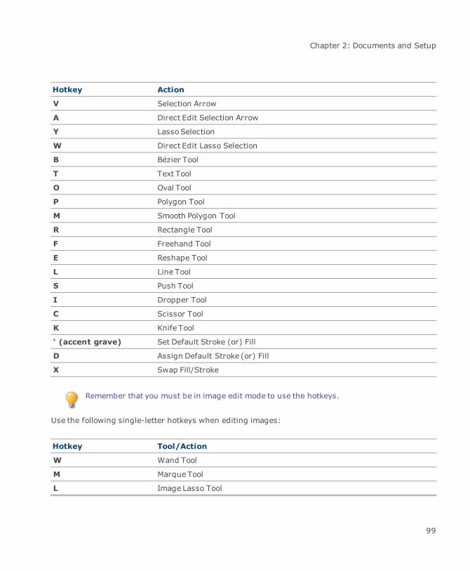
Chapter 2: Documents and Setup
Hotkey Action
V Selection Arrow
A Direct Edit Selection Arrow
Y LassoSelection
W Direct Edit Lasso Selection
B Bézier Tool
T Text Tool
O Oval Tool
P Polygon Tool
M Smooth Polygon Tool
R Rectangle Tool
F Freehand Tool
E Reshape Tool
L Line Tool
S Push Tool
I Dropper Tool
C Scissor Tool
K Knife Tool
‘ (accent grave) Set Default Stroke (or) Fill
D Assign Default Stroke (or) Fill
X Swap Fill/Stroke
Remember that you must be in image edit mode to use the hotkeys.
Use the following single-letter hotkeys when editing images:
Hotkey Tool/Action
W Wand Tool
M Marque Tool
L Image Lasso Tool
99
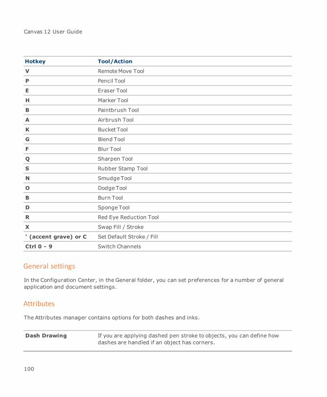
Canvas 12 User Guide
Hotkey Tool/Action
V RemoteMove Tool
P Pencil Tool
E Eraser Tool
H Marker Tool
B Paintbrush Tool
A Airbrush Tool
K Bucket Tool
G Blend Tool
F Blur Tool
Q Sharpen Tool
S Rubber Stamp Tool
N SmudgeTool
O Dodge Tool
B Burn Tool
D Sponge Tool
R Red Eye Reduction Tool
X Swap Fill / Stroke
‘ (accent grave) or C Set Default Stroke / Fill
Ctrl 0 - 9 Switch Channels
General settings
In the Configuration Center, in the General folder, you can set preferences for a number of generalapplication and document settings.
Attributes
The Attributes manager contains options for both dashes and inks.
Dash Drawing If you are applying dashed pen stroke to objects, you can define howdashes are handled if an object has corners.
100

Chapter 2: Documents and Setup
Preserve Corners: Select this option to keep the corners intact; i.e.,dashes will not be applied to the corners of objects.
Continue with Dash: Select this option to apply dashes to the cornersof objects.
Inks When working with objects that contain Hatch, Texture, Symbol, orPattern inks, it is possible to magnify these objects without magnifyingthe ink as well.
The following examples show what happens when inks are scaled or not scaled:
Object at 200% magnification(fill ink does not scale)
Object at 200%magnification(fill ink scales)
Color calibration
Use these options to change color settings within Canvas (see "Color management" on page 120).
Display options
In Display Options, you can configure most of the options for screen display. Change display optionsand set the default display options for new documents. You can change these same settings in theDisplay Options manager dialog box.
The items in the Show, Alert, and Preview groups can be individually toggled on and off bychoosing Layout | Display. When a special display option is active, a checkmark appearsnext to the option in the menu.
101
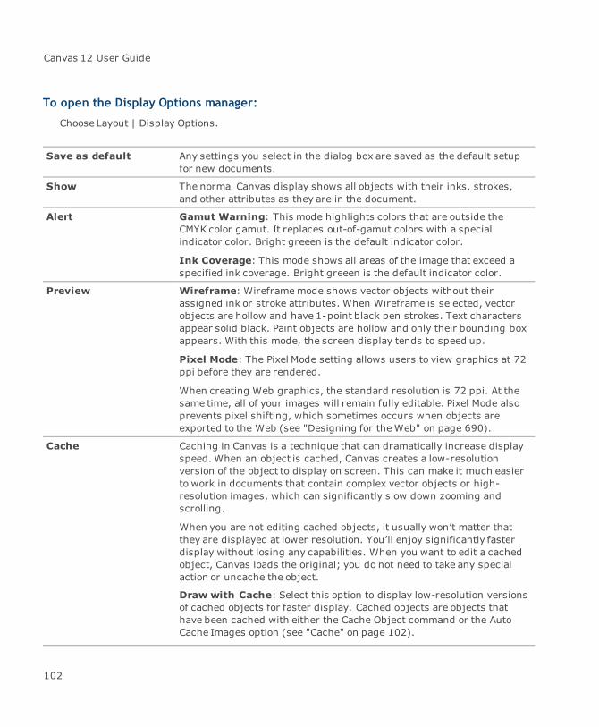
Canvas 12 User Guide
To open the Display Options manager:
Choose Layout | Display Options.
Save as default Any settings you select in the dialog box are saved as the default setupfor new documents.
Show The normal Canvas display shows all objects with their inks, strokes,and other attributes as they are in the document.
Alert Gamut Warning: This mode highlights colors that are outside theCMYK color gamut. It replaces out-of-gamut colors with a specialindicator color. Bright greeen is the default indicator color.
Ink Coverage: This mode shows all areas of the image that exceed aspecified ink coverage. Bright greeen is the default indicator color.
Preview Wireframe: Wireframemode shows vector objects without theirassigned ink or stroke attributes. When Wireframe is selected, vectorobjects are hollow and have 1-point black pen strokes. Text charactersappear solid black. Paint objects are hollow and only their bounding boxappears. With this mode, the screen display tends to speed up.
Pixel Mode: The Pixel Mode setting allows users to view graphics at 72ppi before they are rendered.
When creating Web graphics, the standard resolution is 72 ppi. At thesame time, all of your images will remain fully editable. Pixel Mode alsoprevents pixel shifting, which sometimes occurs when objects areexported to the Web (see "Designing for theWeb" on page 690).
Cache Caching in Canvas is a technique that can dramatically increase displayspeed. When an object is cached, Canvas creates a low-resolutionversion of the object to display on screen. This can make it much easierto work in documents that contain complex vector objects or high-resolution images, which can significantly slow down zooming andscrolling.
When you are not editing cached objects, it usually won’t matter thatthey are displayed at lower resolution. You’ll enjoy significantly fasterdisplay without losing any capabilities. When you want to edit a cachedobject, Canvas loads the original; you do not need to take any specialaction or uncache the object.
Draw with Cache: Select this option to display low-resolution versionsof cached objects for faster display. Cached objects are objects thathave been cached with either the Cache Object command or the AutoCache Images option (see "Cache" on page 102).
102
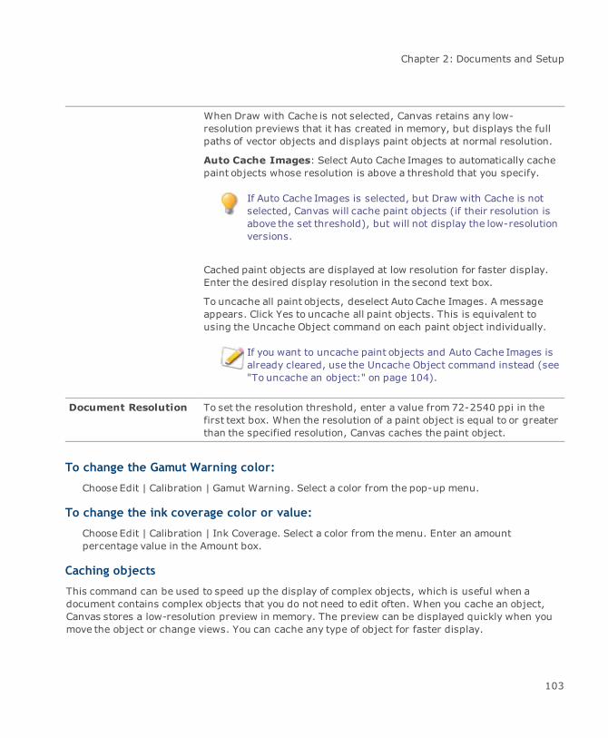
Chapter 2: Documents and Setup
When Draw with Cache is not selected, Canvas retains any low-resolution previews that it has created in memory, but displays the fullpaths of vector objects and displays paint objects at normal resolution.
Auto Cache Images: Select Auto Cache Images to automatically cachepaint objects whose resolution is above a threshold that you specify.
If Auto Cache Images is selected, but Draw with Cache is notselected, Canvas will cache paint objects (if their resolution isabove the set threshold), but will not display the low-resolutionversions.
Cached paint objects are displayed at low resolution for faster display.Enter the desired display resolution in the second text box.
To uncache all paint objects, deselect Auto Cache Images. A messageappears. Click Yes to uncache all paint objects. This is equivalent tousing the Uncache Object command on each paint object individually.
If you want to uncache paint objects and Auto Cache Images isalready cleared, use the Uncache Object command instead (see"To uncache an object:" on page 104).
Document Resolution To set the resolution threshold, enter a value from 72-2540 ppi in thefirst text box. When the resolution of a paint object is equal to or greaterthan the specified resolution, Canvas caches the paint object.
To change the Gamut Warning color:
Choose Edit | Calibration | Gamut Warning. Select a color from the pop-up menu.
To change the ink coverage color or value:
Choose Edit | Calibration | Ink Coverage. Select a color from themenu. Enter an amountpercentage value in the Amount box.
Caching objects
This command can be used to speed up the display of complex objects, which is useful when adocument contains complex objects that you do not need to edit often. When you cache an object,Canvas stores a low-resolution preview in memory. The preview can be displayed quickly when youmove the object or change views. You can cache any type of object for faster display.
103

Canvas 12 User Guide
To cache an object:
1. Select the object to cache.
2. ChooseObject | Options | Cache Object.
3. In the dialog box, enter a preview resolution value, from 2 to 300 pixels per inch, in the textbox. Lower resolutions produce rougher previews.
4. Click OK. Canvas displays a preview of the cached object at the cached resolution.
To uncache an object:
1. Select a cached object.
2. ChooseObject | Options | Uncache Object. Canvas returns the object to its normalresolution.
Document setup
In Document Setup, you can switch the current document type, modify document size andorientation, as well as change document units and scale. You can change these same settings in theNew Document dialog box.
Although you can switch to another document type in midstream, you should save thecurrent document in its entirety and then change the document type.
Defining a drawing scale
The Document scale section has several options in the Pre-defined scales menu. You can also selectCustom from the menu and then define your scale with the “Page distance = world distance”controls.
If you select “1:1” as the scale, you are actually drawing in real-world units; i.e., you aren’t drawing“to scale”.
You can also establish a drawing scale by using the Set Document Scale command (see "Setdocument scale" on page 78).
Functionality options
Use the Functionality Options to setup a range of document options.
Maximize on Opening Opens documents at full screen size. Otherwise, documents open at a
104
Chapter 2: Documents and Setup
standard size that fits anymonitor, but might not fill the screencompletely.
Fit to Window Opens documents so the full layout area can be seen in the center of thewindow. When this option is off, documents open in Home View (100%magnification with the upper-left corner of the page in the upper-leftcorner of the window).
Paste as MetaObject When copying from other applications, select this option to paste as ametaobject (see "Inserting objects into Canvas documents" on page152). Text, however, is pasted as OLE if this option is enabled. If youcopy both an object and text, they will paste as OLE.
Create backup whensaving
Saves a copy of the current document each time you save changes to thedocument. The backup copy has the extension “.bak,” and Canvas savesto this same file each time.
Canvas 6-style objectlocking
When you lock an object or group of objects, you can select and copylocked object(s) by clicking on the object or group of objects. Copiedobjects will not be locked.
No BackgroundUpdates
Prevents Canvas from redrawing open Canvas documents when you areworking in another application. This option lets other applications runfaster when Canvas is in the background.
Show informationtooltips
Displays information, tips and shortcuts in small boxes that appearwhen you point at an item, such as a tool, button, or object. For example,if you move the pointer over the Copy button in the Tool Bar, Canvasdisplays the command name and shortcut. Canvas also displays usercomments when you point to an object that has comments, and displaysinformation when you point to an ink in the Inks palette. For color inks,Canvas displays color system information. For example, if you point to aCMYK ink, the color values such as “5c 2m 92y 0k” appear in a pop-upbox. For other inks, Canvas displays the ink name.
Select Across VisibleLayers
Lets you select objects on all visible layers in a document, rather thanjust the active layer.
If this option is off, you can still select objects on other visiblelayers by pressing Tab and clicking the objects.
Search selection onclicks
When this option is on, you can drag a selected object from behindanother object. If this option is off, you can drag only the front object,because dragging deselects a back object.
105
Canvas 12 User Guide
Scale Stroke Weight When you scale an object by dragging its selection handles, if the objecthas a solid pen stroke, Canvas will scale the pen weight proportionatelywith the object.
AutoSave Select this check box if you want Canvas to automatically save adocument after a certain period of time. The time periods are designatedin minutes.
Freeform Selection Lets you place objects in freeformmode by clicking already-selectedobjects. Otherwise, you must use the Effects | Freeform command to putan object in freeformmode.
Number of UndoLevels
Enter a number in the Min box to set the minimum number of actionsthat Canvas can reverse. The default is three. Enter a number in the Maxbox to specify themaximum number of actions that Canvas reverse. Thedefault is 10.
To undo an action in Canvas:
Do one of the following:
Choose Edit | Undo.
Choosing Window | Palettes | Undos.
See "Undoing, redoing, and repeating actions" on page 53.
Painting
The Painting manager lets you set preferences for displaying and editing paint objects and images.
Brush Pointer These options let you change the pointer displayed for painting tools.The default pointer is a symbol of the current painting tool.
Standard Pointer: Displays the icon for the current painting tool.
Precise Pointer: Displays a crosshair pointer. The intersection of thecrosshair is the center of the current brush.
Brush Size Pointer: Displays an outline of the current brush as thepointer.
Open the context menu to change the pointer while you edit apaint object.
106

Chapter 2: Documents and Setup
Filter Operations Apply individually: Apply filter operations individually.
Combine channels & apply: Combine channels and then apply filteroperations.
Legacy Plug-ins Click the Browse button to set the location of Photoshop-compatibleplug-ins for use in Canvas. In the directory dialog box that appears,select the folder containing the plug-ins. The path name of the folderappears below the Plug-ins button on the Painting tab. Installed plug-infilters appear in the Image | Filters submenu.
Hide Plug-in Host Warning: Suppresses themessage that Canvasdisplays if it tries to load a software plug-in that requires a specific hostprogram. Deselect this option if you want Canvas to display the messageso you can choose whether to load the plug-in.
Additional options Separate grayscales as black: Select to separate grayscale paintobjects on the black plate only. Deselect this option for Canvas to treatgray color values as RGB colors that will be separated as CMYK grays.
Select through transparency: Select through transparency.
Display channel previews in color: Makes channel previews in theImage Channels palette appear in color rather than shades of gray.
Anti-aliased clipboard: Anti-aliases vector and text objects pastedfrom the Clipboard into a paint object.
Anti-aliased Canvas objects: Anti-aliases Canvas vector and textobjects drawn in a paint object. For example, if you add text to a paintobject in edit mode, Canvas rasterizes and anti-aliases the text.
Personality manager
Use the Personality Manager to select your use of Canvas and color output needs. The Toolbox andrelated tool palettes will be rearranged to suit your needs.
At any time, you can make modifications to the Personality Manager if your needs change.
To access the Personality Manager:
Choose File | Configuration Center or Canvas | Configuration Center and click the PersonalityManager option in the General settings. Make your changes and restart the program.
Changes in the Personality Manager affect the Canvas settings file.
107
Canvas 12 User Guide
Screen rendering
Use the Screen Rendering options to setup the way images are rendered.
Vector quality The options in this menu affect the entire screen display in Canvas.
Draft: Provides the fastest screen display by drawing vector objectsless smoothly. Choosing this option can increase display speed by300%.
Normal: Provides fast screen display and draws smooth vector objects.This is the recommended setting and is selected by default.
Anti-aliased: Significantly smooths all objects on screen, including textand vector objects by anti-aliasing their edges. However, this anti-aliasing slows the display compared to Draft or Normal settings. Theeffect of the anti-aliased option is independent of the anti-aliased optionon the Display tab. If either option is selected, text is anti-aliased andvice-versa.
Anti-aliased is especially useful when you create screen shots ordisplay slide shows on screen.
Image When activated, this feature will significantly enhance the visual qualityof scaled images. Interpolation takes placewhenever an image needs tobe reduced or downsampled. In other words, whenever the number ofpixels being displayed is less than the available number of pixels at thedestination. An example of downsampling would be when a 300 ppiimage is set to be displayed at 100%.
Interpolation is a mathematical procedure which estimatesvalues of a function at positions between listed or given values.
Nearest Neighbor: will remove some pixel information from yourimage; however, if used, this setting will be the fastest. NearestNeighbor setting merely gathers pixel data from the “Nearest Neighbor”of each pixel, therefore Interpolation does not actually occur.
Bilinear: Uses a bilinear interpolation algorithm during downsampling.This setting can be used if you work with line art and may be applied tosome photographic images.
108

Chapter 2: Documents and Setup
Bicubic: Is an appropriate setting if you work primarily withphotographs.Due to a blurring effect, we do not recommend the Bicubic setting if youwork with line art.
Auto: Is the optimal setting for interpolation of a photographic image.The Auto setting automatically chooses the best Interpolation optionbased on the image, its resolution, and current magnification.
Pasteboard Color Use the color palette to select a color for the pasteboard area.
Object Caching Keeps screen images in memory so the display refreshes significantlyfaster when you move or edit objects. This is the recommended option.If you deselect this option, less memory (up to 4 MB) is used for screendisplay, but displaying complex images might be very slow.
Compatibility Mode(Slower)
Uses compatibility mode.
Show All Previews inFile Open
Shows all previews in the Open dialog box.
Image Edit Lets you control how transparency appears when a paint object is in editmode.
No preview: Displays a checkerboard pattern to representtransparency in an image. This isolates an image from backgroundobjects, which can be helpful for editing complex compositions.
Items in background only: Displays transparency in an image duringediting. Objects behind the image are rendered realistically while youedit. (If no objects are behind the paint object, the document’s whitelayout area shows through transparent areas.) Objects in front of a paintobject are hidden during image editing.
Preview all: Displays both background and foreground transparencyduring image editing. This is themost accurate preview.
109
Canvas 12 User Guide
Selection
Show originals whendragging and resizing
When you drag or resize an object, it will follow the pointer and alsoappear in its original position until you release the mouse button.
Selecting this option means that when you drag an object, an outline ofthe object (without pen ink, fill ink, or stroke) will follow the pointer.
Allow Drag in PathEdit Mode
Allow dragging in path edit mode.
Offset for duplicatingobjects
Tells Canvas how far (in pixels) from the original to put object copieswhen you choose Edit | Duplicate or Edit | Paste.
Offset for movingobjects
You can specify the number of pixels that objects move when you use acombination of modifier and arrow keys. For example, with the settingsshown here, Ctrl+Right Arrow moves a selected object 50 pixels to theright, and Alt+Right Arrow moves it 10 pixels to the right.
Selection Handle Size Select a size for selection handles.
Auto-scroll toselection
Keeps objects that you move using the arrow keys in view by scrollingthe document window.
User info
Specify a name and initials for object comments, which you can insert using the Comments command(see "Attaching comments to objects and using Markup tools" on page 206). You can also establishthe default directory for downloading clipart with the Symbol Library palette.
Name Type a name in the text box. When you attach a comment to an object,Canvas associates the name you enter with the comment. By default,Canvas uses the name entered when Canvas was installed.
Initials Type initials in the text box. When you attach comments to an object,Canvas associates these initials with the comment.
Text settings
In the Configuration Center, in the Text folder, you can set preferences for how the applicationhandles text.
110
Chapter 2: Documents and Setup
Auto correct
Use these options to specify corrections you want Canvas tomake as you type.
Correct Two InitialCapitals
Corrects a word that you type beginning with two capitalized letters.
Capitalize first letterof sentences
Capitalizes the first letter you type following typical sentence-endingpunctuation, such as periods, question marks, or exclamation points,even if thesemarks are followed by a quotation mark or parenthesis.Canvas may or may not capitalize the first letter following unusualpunctuation, such as Web site addresses or abbreviations in the middleof sentences, so sentences containing unusual punctuation should bechecked.
Auto Correct does not capitalize the next word if you insertsentence-ending punctuation in existing text.
Capitalize names ofdays
Capitalizes the full name of weekdays; e.g., this option replaces“saturday” with “Saturday.” It does not expand abbreviations for daynames, such as “wed.” or “Thurs.,” unless you add these abbreviationsto the replacement list.
Correct AccidentalUsage of the CapsLock Key (Windowsonly)
Corrects non-standard word capitalization. If the first letter of a word islowercase and the other letters are uppercase, this changes the firstletter to uppercase and the rest of the letters to lowercase; e.g., thisoption replaces “rEPEL” with “Repel.” If the first two letters of a word areuppercase and the rest are lowercase, this changes the first letter touppercase and the rest of the letters to lowercase; e.g., replacing“REpel” with “Repel”.
Replace Text as YouType
Replaces text that you typewith any specified replacement text. Each setof typed text and replacement text appears in the scrolling list in theAuto Correct dialog box (see "Setting up text replacement" on page621).
Dictionary
Use this option to add an unlimited number of words to the personal dictionary. You can also deletewords. By adding words to the User Dictionary, you can “teach” Canvas new words and specialterms, and prevent Canvas from stopping unnecessarily while checking spelling (see "Modifying theUser Dictionary" on page 628).
111

Canvas 12 User Guide
Type
The Type settings in the Configuration Center let you customize options for text and typography.
Text Input When Typing Into Document: Select either Auto type into object orAllow single letter shortcut.
Auto type into object: This option allows you to automatically begintyping text characters into a selected object.
Allow single letter shortcut: If activated, you will be allowed toaccess the vector and image editing tools using simple single-lettershortcuts. The list below details the various hotkey commands and howtheymay be applied.
Use Smart Quotes: Select this option if you want Canvas to insert truetypographical apostrophes (’), single quotation marks (‘’), and doublequotation marks (“”) when you type these characters with the Text tool.Otherwise, these characters appear as straight tickmarks, or foot (')and inch (") marks. Of course, the actual appearance of the charactersdepends on the design of the typeface in use.
The character that Canvas inserts when you type a quotation markdepends on the position of the insertion point in the text, and its positionrelative to other quotation marks; e.g., Canvas always inserts an openquotation mark (“) when you type a quotation mark immediatelyfollowing a space.
Use Smart Quotes has no effect on text that you type with thePath Text tool.
Use Greeked text: Select this option if you want Canvas to replacelines of text characters with gray bars, which speeds up screen redraw.
The Greeked text setting does not affect printing. You shouldset the size the same as most body text in your documents. Thislets you view headlines and display type normally, while Canvasreplaces the body text at 100% magnification. Then, when youzoom in to edit the body text, it will appear normally at thehigher magnification.
Enter a size in points in the adjacent text box. When this setting is
112

Chapter 2: Documents and Setup
selected, Canvas replaces text at the specified size and smaller when thedisplay magnification is 100% or less; e.g., if you specify 12 points, andzoom to 200%, Canvas replaces any text that is 6 points or smaller. Ifyou zoom to 50%, Canvas replaces text that is 24 points or smaller.
Drag & Drop Text: Enable this option so you can highlight text anddrag that text to a new location within the same text object.
113

Canvas 12 User Guide
Copy & Paste Smart Copy: With this option on, if you copy and paste text that beginsa paragraph, Canvas pastes the text as a new paragraph using theoriginal paragraph settings. With this option off, Canvas pastes text intothe current paragraph using the existing paragraph settings.
Replace Selection: Activating this function allows you to automaticallyreplace selected text when you paste into a Canvas document. If thisoption is not activated, text will be pasted into the center of yourdocument.
Pasted Text Box Size: Enter the point size that you would like yourtext box to be when you paste text into your document. The setting thatyou choose will become the default size for all text boxes that will becreated when you paste text into your document.
Font History Activate font history: Select this option to list the most recently usedfonts at the top of your Fonts menu.
# of fonts to keep in history: Select the number of fonts that are tobe stored in the history.
Clear font history: Click this button to empty the recent font history.
Additional Options Enable two-byte script: This option tells Canvas to accommodate textcharacters that require twice as much data (two bytes) as textcharacters in most Western languages. This makes it possible to createdocuments using specialized two-byte fonts, including Chinese, Korean,and Japanese (see "Tools and options for two-byte and vertical text" onpage 564).
Auto word select: When you use the I-beam pointer to highlightspecific text, this option ensures that you select only whole words (allcharacters between blank spaces). As you drag to highlight text, Canvasdetects when you drag over a space. As you continue to drag, Canvaslocates the next space and selects the characters in between.
Draw text as Bézier: When using a 256-color display, Windowscannot dither colors in text to approximate a non-system color; instead,Windows uses the closest solid colors. Turning this option on tellsCanvas to redraw text as objects, which lets Windows dither colors whennecessary. This method is resource-intensive and can be slow; turn thisoption on only if you need to see dithered color in text on a system with a256-color display.
Multi-Column Font Menu: When activated, you will view all of thefonts in your system in a multi-column format. If this feature is notactivated, then you will view your fonts in a single-column format.
114
Chapter 2: Documents and Setup
If you elect to use the single-column format, use the navigationarrows located at the top and bottomof the list to scroll throughthe fonts list. To see the list of available fonts, choose Text |Font.
Printing settings
The Printing settings let you control the appearance of printed output. These settings affect printedoutput when you use the Print as: Composite setting in the Print dialog box, and do not affect printingwhen you use the Print as: Separations setting.
Gamut warning
This mode highlights colors that are outside the CMYK color gamut. It replaces out-of-gamut colorswith a special indicator color. By default, the indicator color is bright green (see "Printing settings"on page 115).
Ink coverage
This mode shows all areas of the image that exceed a specified ink coverage. By default, the indicatorcolor is bright green (see "Printing settings" on page 115).
115

Canvas 12 User Guide
Output settings
Resolution Use these settings to control the appearance of printed documents.
Output to maximum resolution: Select this check box to printdocuments at the printer’s highest resolution. This setting disablesimage-reduction options and fast-printing features of QuickDraw®printers, which require a setting of 72 dpi (see "Output resolution oftransparency effects" on page 687).
If you print documents to a PostScript printer, it’s a good idea to selectthis option; however, if you are using Japanese fonts (two-byte), youcan deselect the Output to maximum resolution check box, and then usethemenu to select 300 dpi to speed up printing.
When Output to maximum resolution is not selected, you can choose theresolution (from 72 to 2,540 dpi) to use in the Resolution menu.
Halftone Set the halftone screen frequency and the halftone screen angle forcomposite printing. You can also use the printer’s default halftonesettings.
For most desktop publishing purposes, the printer’s default settings areprobably the best to use. For commercial printing, you might need tospecify a particular frequency and angle for the best output. If you aresending documents to a commercial printer, ask about the appropriatehalftone screen settings.
Use printer default: Select this option when you often print to desktopdevices such as laser printers, and the default halftone screenfrequency and angle are appropriate for your documents.
Frequency: To specify a halftone screen frequency, deselect the Useprinter default check box, and enter the frequency in lines per inch inthe text box. A higher frequency requires a higher printer resolution toproduce the same number of grayscale levels in printed halftones.
Angle: If you want to specify the angle of the screens used forhalftoning, rather than use the printer’s default setting, deselect the Useprinter default check box, and enter the angle in the Angle check box.
Postscript text type All Bezier
No Bezier
Combination
116
Chapter 2: Documents and Setup
Printer Options PS L2 (Faster printing of text): Allows you to send a block of text tothe printer for faster printing of text. If disabled, text is sent characterby character.
Screen enhancement feature for true halftones: This option,when enabled, always prints halftones at the highest possible LPI. Ifdisabled, a halftone is printed at the printer’s resolution.
Document bleed size: By default, the bleed size is set to 9 pt (1/8 in).Enter a new value in the text field.
Registration marks
Define the appearance of the registration marks. By default, the fill is white and the size is 72 pts(see "Drawing registration marks manually" on page 302).
Measurements settings
In the Configuration Center, in the Measurements folder, you can define units, setup grids andguides, and set the unit of measure used in the rulers and drawing scale.
Define units
You can further customize the rulers by adding units of measurements, modifying the definitions ofexisting ones, or deleting them (see "Setting up rulers" on page 74).
Units To add units: Click the Add button. In the Add Unit dialog box, enter aUnit name, Plural name, and Abbreviation. Select a Length and unit ofmeasurement on which to base the new unit. Select the Minor divisionsfor the unit; e.g., if you wanted to have a unit that was based on 1 inch,enter 1 for Length and select inches from the menu. Then, select theMinor divisions that you want to use.
You can add this unit to any future documents by selecting theAdd to all new documents check box in the Add Unit dialog box.
To modify units: Select an existing unit and then click the Modifybutton. In the Modify Unit dialog box, you can change the Abbreviationand Minor divisions.
117
Canvas 12 User Guide
To delete units: Select a user-defined unit and click the Removebutton.
You cannot delete default units; i.e., inches, centimeters, etc.You also cannot delete units that are currently being used as thedocument unit. Change the document unit first.
Grids and guides
You can use grids and guides to aid in positioning objects in a document. You can also turn on thesnap-to-grid and snap-to-guide features tomake Canvas snap objects into alignment with thenearest grid or guide.
Use these settings to create an alignment grid (see "Using the alignment grid" on page 80).
Grid Line distance X: This is the distance from one vertical grid line toanother.
Line distance Y: This is the distance from one horizontal grid line toanother.
Snap factor X: This value sets the snap points along the horizontallines of the grid and guide.
Snap factor Y: This value sets the snap points along the vertical linesof the grid and guide.
Snap to X/Snap to Y: Select one or both options tomake objects snapto the snap points on both sets of grid and guide lines.
Guides Snap distance in points.
You can also change these settings using the Grids and Guides manager, available from the Layoutmenu.
To open the Grids and Guides manager:
Choose Layout | Grids and Guides.
118

Chapter 2: Documents and Setup
To show or hide grids:
Do one of the following:
Toggle the Grids check box in the Properties bar.
Choose Layout | Display | Show Grids/Hide Grids.
To show or hide guides:
Do one of the following:
Toggle the Guides check box in the Properties bar.
Choose Layout | Display | Show Guides/Hide Guides.
To turn on snap-to-grid:
Choose Layout | Snap To | Grid. Choose the command again to turn off snap-to-grid.
To turn on snap-to-guide:
Choose Layout | Snap To | Guide. Choose the command again to turn off snap-to-guide.
Ruler
The Ruler manager lets you choose measurement settings, such as document units, document scale,and numerical format. If you’re accustomed to creating large illustrations, such as billboards or 2-Darchitectural drawings, Canvas gives you the freedom to create a document in its actual size anddraw in real-world units.
Document unit Select a unit of measurement from the drop-down list. This unit isdisplayed in the rulers, in the Object Specs palette, and in Propertiesbar.
Document scale Select a pre-defined scale or set a custom scale.
Pre-defined scales: Select a common scale from the drop-down list.
Page distance/World distance: Create a custom scale by enteringthe ratio and units of measurement for the page distance versus theworld distance. For example, you could create a scale that was 1 inch onthe page to 1 foot in the world.
Format Select the formats for the numbers, angles, and coordinates. For thenumber format, you can choose from no decimals to six decimals, oreven use fractions (see "Floating point technology" on page 357).
119

Canvas 12 User Guide
Numbers: Select a number format.
Coordinates: Select a format for displaying coordinates.
Area format: Select a format for displaying area.
Angles: Select Euclidean or Clock-like.
Image/multimedia settings
In the Configuration Center, in the Image/Multimedia folder, you can set preferences for a number ofapplication tools and effects.
Color management
Canvas uses the KodakDigital Science Color Management System or its own internal colormanagement system to achieve accurate color reproduction in printing and display. The active colormanagement system handles conversions from one color mode to another.
The Kodak Color Management System supports ICC (International Color Consortium) profiles. Use ICCprofiles to calibrate monitors and output devices.
File installation and placement
During installation, several files that are required to use the Kodak Color Management System arecopied to the system. After installation, do not move, rename, or delete these files; otherwise, theKodak external tool won’t load.
Installation places various.DLL files throughout the system. It also creates a KPCMS folder at the rootlevel of the hard disk if one doesn’t exist already.
To install additional ICC profiles, refer to your system documentation.
On Windows 2000, XP, and Vista, Kodak ICC profiles are stored in the Color Profiles folder in theCanvas folder. By default, Canvas installs Kodak’s generic ICC profiles only.
Kodak ICC profiles
ICC profiles are used for color management by Canvas and other programs. Canvas installs Kodak ICCprofiles that are appropriate for most monitors and color printers.
120

Chapter 2: Documents and Setup
You can obtain additional ICC profiles for specialized devices, such as film writers, graphicsarts monitors, and prepress proofing devices from the device’s manufacturer.
To download ICC profiles from ACD Systems of America:
1. Go to www.acdamerica.com.
2. Click the Downloads link on the navigation bar.
3. On the Downloads page, click the ICC Profiles in the Canvas Add-on Files section.
4. Select the folder, then click profile_index. This displays a list of all available ICC profiles.
5. Scroll through the list to find your device name. The profile file name appears first on the linefor each device.
6. To download the file, click Back in your browser. Open the appropriate device folder and clicka file name to download the ICC profile file.
To change color settings within Canvas:
1. To change the color management settings, choose Edit | Calibration | Color Settings.
2. In the Configuration Center, iIn the Color Calibration manager, select profiles and otheroptions (see "Color Settings options" on page 121).
3. Click OK to implement the settings.
Color Settings options Use
RGB Selects the ICC profile for conversion to and fromRGB color space.
CMYK Selects the ICC profile for conversion to and fromCMKY color space.
Lab Selects the ICC profile for conversion to and from LAB color space.
Monitor Select a monitor ICC profile that matches your monitor, or use the defaultprofile. To change the profile, choose Other. In the dialog box, in theupper pane, select a profile and click Open.
Printer Select an ICC profile for your printer or use the default profile. To changethe profile, choose Other. In the dialog box, in the upper pane, select aprofile and click Open.
Engine Choose the Kodak Digital Science CMS or the internal Canvas colormanagement system.
121

Canvas 12 User Guide
Color Settings options Use
Intent Choose a rendering intent:
Perceptual (Images): Maintains relative color values as the values aremapped to the printer gamut. This method preserves the relationshipamong colors, though color values can change.
Saturation (Graphics): Maintains relative saturation values of colors.Colors that are outside the printer gamut are converted to the closestcolors with the same saturation that are inside the printer gamut.
Relative Colorimetric: Leaves colors that fall inside the gamutunchanged. This method usually converts out-of-gamut colors to colorsthat have the same lightness but fall just inside the gamut.
Absolute Colorimetric: Disables white-pointmatching whenconverting colors. This option is not generally recommended.
Simulate print colorson display
Select to simulate on the monitor the appearance of the CMYK colors thatwill be printed.
Color management tips
If you require the highest quality color matching and output, becoming familiar with the factors thatcan cause problematic color shifts can help you to avoid unexpected results.
In general, the Kodak color management system handles conversion between color systems, such asRGB and CMYK. The system makes the conversion as accurate as possible, taking into account thecharacteristics of the color display and color printing devices.
If you want to prevent even slight changes in color values, avoid conversion from one color system toanother. When you paint in an image, use the color system that matches the image mode; e.g., useRGB colors for RGB Color mode, and CMYK colors for CMYK Color mode.
If you paint a CMYK color into an RGB Color mode image, Canvas converts the CMYK color values toRGB values. When color calibration is active, the color management system uses the specifications ofthe selected ICC profiles in the conversion process.
You must use a printed swatchbook to view the printed appearance of a color. You shouldnever rely entirely on the appearance of a color on screen.
Avoid using RGB color in a document that will be printed commercially using process (CMYK) colors.When you specify process colors, it’s best to use a matching system ("Color systems" on page 232).
122
Chapter 2: Documents and Setup
Preferences for two-byte text entry
The options for the Inline preferences let you specify whether you want to always enter two-byte textdirectly into a document, or use a text-entry window when the apparent type size is outside a rangethat you have set. This feature is available only when you are running system software that supportstwo-byte fonts, and are using two-byte fonts to enter text into a document. This preference does notaffect printing.
Using a low zoom level can make it difficult to see text as you type. By using the text-entry window,you can see and edit text in the window, regardless of the current view magnification level.
To set inline text-entry preferences:
1. Choose File | Configuration Center.
2. In the Configuration Center, open the Inline manager within Text settings.
You must first enable two-byte script in the Typemanager.
3. Specify the following options, and then click OK to implement the current settings:
If you always want to use a text-entry window, regardless of the size of the type, selectthe Never option.
If you want a text entry window to appear when you type text at some apparent typesizes, select the “For text from” option. Type a number from 6 and 255 in each text box.These numbers set the range in which the text-entry window does not appear and youtype directly into a document.
A character’s apparent size is the size at which it appears on screen, based on the current viewmagnification level; e.g., 12 point type appears to be 12 points at 100%; at 200%, it appears to be24 points; at 50%, it appears to be the size of 6 point type.
Using the text-entry window
If you choose the “For text from” option and type text in a document at an apparent point size that isoutside the specified range, the text-entry window appears at the bottom of the screen. You can typeand edit text directly in the window. To enter the text into the current document, press Enter.
If the apparent size of text changes because you change the view magnification, actual point sizesthat are beyond the specified “For text from” rangemight not cause the text-entry window to open. Inthis case, you can type the text directly into the document.
123
Canvas 12 User Guide
Customizing the keyboard and Toolbar
Via the Customize dialog box, you can assign keyboard shortcuts to commands, tools, attributes,object styles, and font styles. You can also place buttons for these items on the Toolbar.
To customize the keyboard and Toolbar:
Choose File | Customize.
Customize dialog box
Use the options in the Customize dialog box to select items, and then create keyboard shortcuts andplace buttons on the Toolbar.
Category Choose the category of items to customize. The contents of the scrollinglist change according to the selected category.
Sub-Category Only active if Menus is selected in the Category menu. The commands inthe selected menu appear in the scrolling list.
Scrolling list Displays all tools or styles in the selected category or subcategory (formenus). For inks and strokes, the list contains the inks or strokes youselect from the pop-up palettes. Select an item in the scrolling list toassign a shortcut to it or to place a button for it on the Toolbar. Theselected item is highlighted.
Current Shortcut Key Displays the current keyboard shortcut for the selected item, if ashortcut exists.
Press New ShortcutKey
With an item selected in the scrolling list, press the keyboard keys youwant to assign to the item. To use a modifier key, press and hold Shift,Ctrl, or Alt. Press a letter, number, or function key. The new shortcutkeys appear in the box.
Menu icon ClickModify to open the Modify icon dialog box and customize themenubar icons. Click Restore to return the icons to their default appearance.
Assign Click to assign the keystrokes in the Press New Shortcut Key box to theselected item.
Remove Click to remove the current shortcut keystrokes from the selected item.
Reset All Click to restore the default shortcut keys to all items.
Reset Click to restore the default shortcut keys to the item selected in thescrolling list.
Palettes A pop-up palette appears when the Category selection is Inks; three
124

Chapter 2: Documents and Setup
palettes appear when the Category is Strokes. Select an ink or strokefrom the palette. The selected item appears in the scrolling list and onthe Toolbar.
Remove Selection When the Category selection is Inks, Strokes, Object Styles, or FontNames and Sizes, click the Remove Selection button to remove a selecteditem from the scrolling list. This also removes a button for the item fromthe Toolbar.
Save Set After you customize Canvas, you can save the current configuration in afile. You can create other custom configurations and save these inconfiguration files. A configuration file stores all the current keyboardshortcut assignments and the setup of buttons on the Toolbar.
Click Save Set to create a file of all current shortcut keys and Toolbarbuttons. In the directory dialog box, type a name for the file and clickSave.
Load Set Click Load Set to import a file of shortcut keys and Toolbar buttons. Inthe directory dialog box, select the file to load and click OK. Canvasresets the shortcut keys and the Toolbar according to the configurationstored in the file.
Clear All Click Clear All to clear all of the customized settings in the scrolling listand all buttons on the Toolbar.
Close Click to close the Customize dialog box. Inks or strokes added to thescrolling list remain in the list when you close the dialog box.
Choosing a category to customize
You can choose items to which you want to assign shortcuts or add to the Toolbar. The followingitems are available in the Category menu.
Menus: If you select this item, you must choose one of the following menus from the Sub-Category menu: File, Edit, Text, Object, Layout, Effects, Image, and Window.
Tools: The names of the tools and their icons appear in the scrolling list. Their respectivekeyboard shortcuts are also indicated in the Current Shortcut Key field.
Inks/Strokes: Next to the scrolling list, a pop-up palette displays preset inks, or three pop-up palettes display pen strokes, dashes, and arrows. Select an ink or stroke from a palette.The item you select appears in the scrolling list and as a button on the Toolbar.
125

Canvas 12 User Guide
To remove an ink or stroke from the scrolling list:
1. Select it and click Remove Selection; if the item is on the Toolbar, this removes it from theToolbar also.
2. In the font size box, select a size and then press the Add Size button. The font size appearsin themain scrolling list, and a font size button appears on the Toolbar.
To choose a font:
Select a name from the menu. The font appears on the scrolling list, and a font button appears onthe Toolbar.
To customize keyboard shortcuts:
1. In the Customize dialog box, select an item in the scrolling list. If the item has a keyboardshortcut, the Current Shortcut Key box shows the shortcut keys.
2. To assign a keyboard shortcut, press the keyboard keys you want to use. The keys you typeappear in the Press New Shortcut Key box. Click Assign to assign the new keys to the item.
If the keys you type are assigned to another shortcut, themessage Currently assigned to: appearsbeneath the Press New Shortcut Key box.
Certain keys are restricted, so pressing them will not display their values. Other shortcutsare reserved by Canvas, so they can be assigned, but not applied to some procedures; e.g.,Ctrl+1, Ctrl+2, and Ctrl+3 cannot be used in painting.
You can’t assign single keys as shortcuts; e.g., you can’t assign “H” or “F7” to an item.
To remove shortcut keys from the selected item:
Click Remove.
To restore the default shortcut keys to all commands:
Click Reset All.
To restore the default shortcut keys to one command:
Select the command in the scrolling list and click Reset.
To assign shortcuts to inks:
Create shortcut keys for specific fill inks and pen inks.
126
Chapter 2: Documents and Setup
To assign a shortcut key to a fill or pen ink:
1. In the Customize dialog box, select the ink in the scrolling list.
2. Type the keyboard keys you want to use. The keys you type appear in the Press New ShortcutKey box.
3. Under the box, select whether you want the ink to be a Fill or Pen ink.
4. Click Assign to assign the new keys to the ink.
To place buttons on the Toolbar:
Do one or both of the following:
Select an item in the scrolling list. Inks, Strokes, Object Styles, and Fonts appear on theToolbar automatically.
For Menus and Tools, double-click the item in the scrolling list to add it to the Toolbar. Abutton for the selected item appears on the Toolbar when it is displayed.
To remove an Ink, Stroke, Object Style, or Font button:
Click the Remove Selection button under the scrolling list, or double-click the item in the scrollinglist.
To remove a Menu or Tools button:
Double-click the item in the scrolling list.
To arrange buttons on the Toolbar:
After you place buttons on the Toolbar, you can change their position directly on the Toolbar.
To move a button: Shift-drag the button to a new location.
To remove a button from the Toolbar: Shift-drag the button away from the Toolbar.
To add a separator between Toolbar buttons: Shift-drag the button on the right slightlyto the right. A separator line appears between the button and the one to its left.
Using ink buttons
When you place buttons for inks on the Toolbar, use the buttons to apply fill and pen inks orforeground and background colors.
You can apply fill and pen inks to vector objects and text as well as select foreground andbackground colors for painting.
127
Canvas 12 User Guide
To apply a fill ink or select a background color for painting:
Click the ink button on the Toolbar. If no objects are selected, the ink becomes the current fill inkor background color.
To apply a pen ink or select a foreground color for painting:
Press Ctrl and click the ink button. If no objects are selected, the ink becomes the current pen inkor foreground color.
Saving document templates
You can use a special kind of Canvas document, called a template, as the basis for new documents.Canvas includes many ready-made templates, and you can create your own template documents.Then, when you use the New command, you can select a template — either one supplied with Canvasor one you have created — to create a new document based on the contents and configuration of thetemplate.
A template document stores almost all preferences settings, as well as the settings you specify withthe Document Setup command, and other document setup options, including the following:
Document type
Configuration of layers, slides, pages, sheets and frames
Settings for rulers, grids, guides, and views
Current inks and strokes settings
Text styles and default text settings
Multiple Save options
Canvas stores some settings with the application and not in particular documents, so these settingsare not included in a template document. The settings that aren’t stored in a template include theposition of palettes on the screen and the current set of external tools.
If you create a template with a small amount of type, such as for a letterhead, convert thetype to paths so the template can be used without particular fonts being available.
To save a template document:
1. Choose File | New to create a new Illustration, Presentation, Animation, or Publicationdocument.
128
Chapter 2: Documents and Setup
2. Choose Layout | Document Setup to select measurement units, document size andorientation, and, for Publications, the margins and column layout.
3. ChooseCanvas | Configuration Center to set up preferences for the document.
4. Create or import objects that you want to store in the template.
5. Choose File | Save As. In the Save as typemenu, select Canvas Template and click Save.
For more information, see "Saving Canvas documents" on page 50.
File & data exchange
Canvas supports many standard formats for exchanging files and data with other programs. Thissection explains how to use non-Canvas file formats, including Web image formats. It includesinformation on exchanging files on the Internet and Object Linking and Embedding.
Importing and exporting files
Canvas lets you import and export files in many different formats, letting you easily work withcolleagues who use different applications and formats. Since the native Canvas format (.CVX) savesall the objects, properties, and effects that your document can contain, it's recommended that youalways save your document in this format, in addition to saving or exporting the document in otherformats.
When you save or export a document in a non-Canvas format, you should be aware of the capabilitiesand limitations of that file format, so that you can avoid problems such as lost information andprinting errors. For example, some formats support only one type of data (vector, raster, or text),while others support multiple types.
Importing files
In Canvas you can open a file directly, or you can create a Canvas document and then place one ormore files into it. This lets you work on a single file, or combine files of different formats into a singledocument.
129
Canvas 12 User Guide
To open or place a file:
1. Choose File, then choose one of the following:
Open: Opens the file as a new Canvas document.
Place: Inserts the file in the current Canvas document. This command is available only ifa Canvas document is open.
2. In the Open or Place dialog box, select the file you want to open, then click the Open or Placebutton.
For some file formats, a dialog box presents options for opening files. Select the appropriatesettings, then click OK.
If you open the file, Canvas creates a new document.
If you are place the file, a Place pointer appears. Click where you want to place the top-leftcorner of the file.
To import image files, you can also use the Image | Import command (see "Importingimages" on page 131).
Exporting files
In Canvas, exporting files in different formats is as simple as saving the file in your selected format.Because not all the different file formats support all Canvas objects and effects, it's recommendedthat you always save your document in the standard Canvas (.CVX) format in addition to otherformats.
For example, a TIFF file can save only a single raster image; it does not support text or vector objects.If you save a Canvas document containing vector objects or text in TIFF format, all the objects in thedocument are changed into an image. If you then open the TIFF file, its contents appear as one rasterimage, so you can’t edit the original text or reshape the vector objects.
When you save a document in another format, Canvas creates a new file on disk, but does not closethe document or change the name of the document in the title bar. If you then try to close the Canvasdocument (without saving it in Canvas format), a message asks you to confirm that you want to closethe document without saving it.
Always save your work as a Canvas (.CVX) document, so you can edit your work later inCanvas if necessary.
For more information about exporting files, see "Saving Canvas documents" on page 50.
130
Chapter 2: Documents and Setup
Rendering images
When you are saving objects and select a file format that supports images only, Canvas renders thedocument or selected objects. Rendering creates an image that can be saved in the selected format.The Render Image dialog box has options for rendering (see "Rendering objects and images" on page430 for more information).
Importing and exporting images
In Canvas there are several ways to import raster images into your document. You can open an imagefile directly, place an image in your document, or import the image. When you use the Importcommand, the Import dialog box filters the files you see, so that you can easily find your image files.
Importing images
Importing an image places it in the current document as a paint object. In most cases, Canvas stacksimported images at the center of the current view. You can also choose to import a low-resolutionproxy of an image. The proxy image is linked to the original image file. The Acquire as Proxy option isonly available when you import TIFF, JPEG, and CVI files.
To import an image:
1. Choose Image | Import.
2. In the Select images to import dialog box, select the image you want to import.
3. Click the Import button.
To import an image proxy:
1. Choose Image | Import.
2. In the Select images to import dialog box, select a TIFF, JPEG, or CVI image.
3. Select the Acquire as Proxy check box.
4. Click the Import button.
The proxy image is linked to the image file.
131
Canvas 12 User Guide
For information about importing images with a TWAIN scanner, see "Using TWAIN-compatible scanners" on page 447.
Exporting images
When you export an image from a Canvas document, Canvas creates a file on disk from a singleselected paint object. Using Export is similar to using Save As, except that you must select a paintobject before you choose Export.
To export an image:
1. Select the paint object or image to export.
Images in edit mode can't be exported. Press Esc to exit edit mode.
2. Choose Image | Export, and select a file format.
3. In the Export Image dialog box, type a file name, select a location for the exported file, andthen click Save.
If the image mode of the selected paint object is not supported by the chosen format, theRender Image dialog box appears. In the dialog box, select an image format supported by thefile format. If an image mode is not available in the Modemenu, the selected file format doesnot support that mode (see "Rendering objects and images" on page 430 for moreinformation).
Viewing EXIF information
EXIF (Exchangeable Image File) is a format that stores information in digital images. Almost all newdigital cameras use EXIF to store information on the image such as shutter speed, exposurecompensation, F number, what metering systemwas used, if a flash was used, ISO number, dateand time the image was taken, white balance, auxiliary lenses that were used, and resolution.
Canvas provides quick and easy access tomost of the information that is attached to these images.
132

Chapter 2: Documents and Setup
To view EXIF information:
1. Select an image in your Canvas document.
2. Do one of the following:
Choose Image | DCS information (EXIF).
Right-click the image and choose DCS information (EXIF).
If the image does not contain any EXIF information, the DCS information (EXIF)option is not available.
Exporting EXIF information
When you export an image, if you choose JPEG (8-bit/channel) or TIFF (8-bit/channel or 16-bit/channel) format, you can export the EXIF information with the image. (See "Creating Web pagesfromCanvas documents" on page 714). However, the EXIF data is only preserved if you have notmade changes to the image in the Canvas document, or if you have made changes to the image'spixels, such as if you've fixed red eye. If you have made other changes to the image, such as rotated,skewed, or adjusted the transparency, or if you have composited other objects with the image, theEXIF information is not preserved.
To export EXIF Information:
1. Select an image in your Canvas document.
2. Choose Image | Export | JPEG or TIFF.
3. Type a filename and select a location for the exported image.
4. Click Save.
5. In the Export Options dialog box, select the Include EXIF Data check box.
6. Click OK.
Using Canvas templates
Canvas includes many ready-made templates, and you can create your own template documents.Then, when you use the New command, you can select a template — either one supplied with Canvasor one you have created — to create a new document based on the contents and configuration of thetemplate.
133

Canvas 12 User Guide
A template document stores almost all preferences settings, as well as the settings you specify withthe Document Setup command, and other document setup options, including the following:
Document type
Configuration of layers, slides, pages, sheets and frames
Settings for rulers, grids, guides, and views
Current inks and strokes settings
Text styles and default text settings
Canvas stores some settings with the application and not in particular documents, so these settingsare not included in a template document. The settings that aren’t stored in a template include theposition of palettes on the screen and the current set of external tools.
If you create a template with a small amount of type, such as for a letterhead, convert thetype to paths so the template can be used without particular fonts being available.
To save a template document:
1. Choose File | New to create a new Illustration, Presentation, Animation, or Publicationdocument.
2. Choose Layout | Document Setup to select measurement units, document size andorientation, and, for Publications, the margins and column layout.
3. Choose File | Configuration Center to set up preferences for the document.
4. Create or import objects that you want to store in the template.
5. Choose File | Save As.
6. In the Save As dialog box, navigate to the Canvas\Templates folder.
7. In the Save as type drop-down list, select TPL - Canvas Template.
8. Click Save.
Working with other file formats
When you use other file formats that Canvas supports, you can select options when you open, place,import, save, or export some types of files. Themost common file formats and their options aredescribed in this section. For more information on using file formats, refer to the “Read Me” file. Newinformation that is not in the printed or online documentation will be provided in the “Read Me” filedistributed with the Canvas software.
134
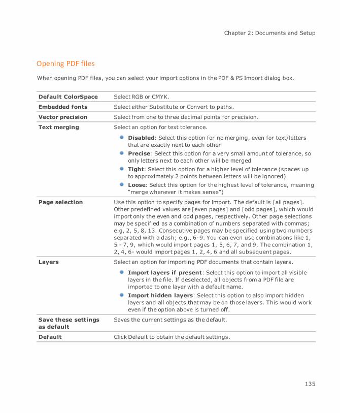
Chapter 2: Documents and Setup
Opening PDF files
When opening PDF files, you can select your import options in the PDF & PS Import dialog box.
Default ColorSpace Select RGB or CMYK.
Embedded fonts Select either Substitute or Convert to paths.
Vector precision Select from one to three decimal points for precision.
Text merging Select an option for text tolerance.
Disabled: Select this option for nomerging, even for text/lettersthat are exactly next to each otherPrecise: Select this option for a very small amount of tolerance, soonly letters next to each other will be mergedTight: Select this option for a higher level of tolerance (spaces upto approximately 2 points between letters will be ignored)Loose: Select this option for the highest level of tolerance, meaning“mergewhenever it makes sense”)
Page selection Use this option to specify pages for import. The default is [all pages].Other predefined values are [even pages] and [odd pages], which wouldimport only the even and odd pages, respectively. Other page selectionsmay be specified as a combination of numbers separated with commas;e.g, 2, 5, 8, 13. Consecutive pages may be specified using two numbersseparated with a dash; e.g., 6-9. You can even use combinations like 1,5 - 7, 9, which would import pages 1, 5, 6, 7, and 9. The combination 1,2, 4, 6- would import pages 1, 2, 4, 6 and all subsequent pages.
Layers Select an option for importing PDF documents that contain layers.
Import layers if present: Select this option to import all visiblelayers in the file. If deselected, all objects from a PDF file areimported to one layer with a default name.Import hidden layers: Select this option to also import hiddenlayers and all objects that may be on those layers. This would workeven if the option above is turned off.
Save these settingsas default
Saves the current settings as the default.
Default Click Default to obtain the default settings.
135
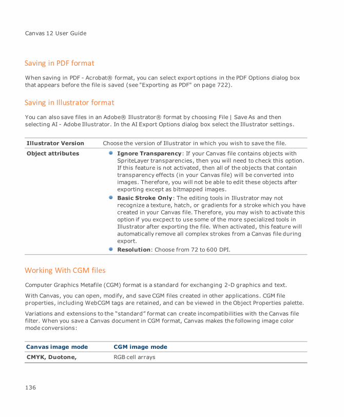
Canvas 12 User Guide
Saving in PDF format
When saving in PDF - Acrobat® format, you can select export options in the PDF Options dialog boxthat appears before the file is saved (see "Exporting as PDF" on page 722).
Saving in Illustrator format
You can also save files in an Adobe® Illustrator® format by choosing File | Save As and thenselecting AI - Adobe Illustrator. In the AI Export Options dialog box select the Illustrator settings.
Illustrator Version Choose the version of Illustrator in which you wish to save the file.
Object attributes Ignore Transparency: If your Canvas file contains objects withSpriteLayer transparencies, then you will need to check this option.If this feature is not activated, then all of the objects that containtransparency effects (in your Canvas file) will be converted intoimages. Therefore, you will not be able to edit these objects afterexporting except as bitmapped images.Basic Stroke Only: The editing tools in Illustrator may notrecognize a texture, hatch, or gradients for a stroke which you havecreated in your Canvas file. Therefore, you may wish to activate thisoption if you excpect to use some of the more specialized tools inIllustrator after exporting the file. When activated, this feature willautomatically remove all complex strokes from a Canvas file duringexport.Resolution: Choose from 72 to 600 DPI.
Working With CGM files
Computer Graphics Metafile (CGM) format is a standard for exchanging 2-D graphics and text.
With Canvas, you can open, modify, and save CGM files created in other applications. CGM fileproperties, including WebCGM tags are retained, and can be viewed in the Object Properties palette.
Variations and extensions to the “standard” format can create incompatibilities with the Canvas filefilter. When you save a Canvas document in CGM format, Canvas makes the following image colormode conversions:
Canvas image mode CGM image mode
CMYK, Duotone, RGB cell arrays
136

Chapter 2: Documents and Setup
Canvas image mode CGM image mode
Grayscale, and LAB color
Black & White CGM versions 1 and 2: RGB cell arrays
CGM versions 3 and 4: Black & White
Multichannel First channel becomes an RGB cell array; other channels ignored
To export as CGM:
1. Choose File | Save As.
2. Select CGM as the file format in the Save As dialog box.
3. In the CGM Export Options dialog box, select the CGM export options.
CGM Version Select a version. If your original document was Version 4 (WebCGM), besure to select this version for export so that any imported data ispreserved in the exported file.
Compliance Select either CALS or ATA.
VDC Precision Select either 16 Bit Integer or 32 Bit Fixed.
Scaling Mode Select either Abstract or Metric.
Export Paint Object If your file contains paint objects, select this option to export them.Deselect this option if you do not want to export the paint objects.
Export Layer AsPicture
If selected, each layer is exported as a separate image. If deselected, thefile will be exported as one image.
Beziers As Polygons If objects contain a fill ink, select this option to preserve it. All bezierswill export as polygons. If this option is deselected and the objects areexported as beziers, the fill color is removed.
Bitonal ImageCompression
This option is enabled if Version 3 or 4 is selected in the CGM Versionmenu. Select either Not Compressed, Group 3 (1-dimensional), or Group4 (2-dimensional).
Font Match Click this button to open the CGM Font Matching dialog box. Select asubstitute font if you want to change the font when exported to CGMformat. The font remains the same in the original file.
Canvas also supports importing CGM and CGM*PIP files (see "Importing CGM files" on page 736).
137
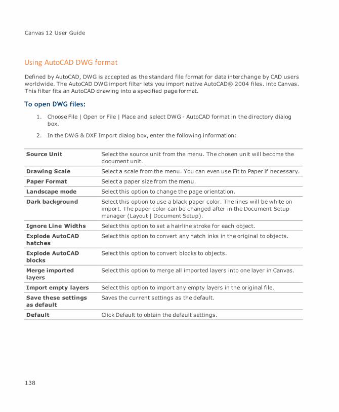
Canvas 12 User Guide
Using AutoCAD DWG format
Defined by AutoCAD, DWG is accepted as the standard file format for data interchange by CAD usersworldwide. The AutoCAD DWG import filter lets you import native AutoCAD® 2004 files. into Canvas.This filter fits an AutoCAD drawing into a specified page format.
To open DWG files:
1. Choose File | Open or File | Place and select DWG - AutoCAD format in the directory dialogbox.
2. In the DWG & DXF Import dialog box, enter the following information:
Source Unit Select the source unit from the menu. The chosen unit will become thedocument unit.
Drawing Scale Select a scale from the menu. You can even use Fit to Paper if necessary.
Paper Format Select a paper size from themenu.
Landscape mode Select this option to change the page orientation.
Dark background Select this option to use a black paper color. The lines will be white onimport. The paper color can be changed after in the Document Setupmanager (Layout | Document Setup).
Ignore Line Widths Select this option to set a hairline stroke for each object.
Explode AutoCADhatches
Select this option to convert any hatch inks in the original to objects.
Explode AutoCADblocks
Select this option to convert blocks to objects.
Merge importedlayers
Select this option tomerge all imported layers into one layer in Canvas.
Import empty layers Select this option to import any empty layers in the original file.
Save these settingsas default
Saves the current settings as the default.
Default Click Default to obtain the default settings.
138
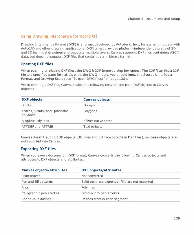
Chapter 2: Documents and Setup
Using Drawing Interchange format (DXF)
Drawing Interchange Format (DXF) is a format developed by Autodesk, Inc., for exchanging data withAutoCAD and other drawing applications. DXF format provides platform-independent storage of 2Dand 3D technical drawings and supports multiple layers. Canvas supports DXF files containing ASCIIdata, but does not support DXF files that contain data in binary format.
Opening DXF files
When opening or placing DXF files, the DWG & DXF Import dialog box opens. The DXF filter fits a DXFfile to a specified page format. As with, the DWG import, you should know the Source Unit, PaperFormat, and Drawing Scale (see "To open DWG files:" on page 138).
When opening a DXF file, Canvas makes the following conversions from DXF objects to Canvasobjects:
DXF objects Canvas objects
Blocks Groups
Traces, Solids, and Quadraticpolylines
Polygons
B-spline Polylines Bézier curve paths
ATTDEF and ATTRIB Text objects
Canvas doesn’t support 3D objects (3D lines and 3D Face objects in DXF files), so these objects arenot imported into Canvas.
Exporting DXF files
When you save a document in DXF format, Canvas converts the following Canvas objects andattributes to DXF objects and attributes:
Canvas objects/attributes DXF objects/attributes
Paint object Not converted
Pen and fill patterns Solid pens are exported; fills are not exported
Arcs Polylines
Calligraphic pen strokes Fixed-width pen strokes
Continuous dashes Dashes start in each segment
139
Canvas 12 User Guide
Canvas objects/attributes DXF objects/attributes
Layer names with spaces or non-uppercase characters
Spaces removed and characters becomeuppercase
Grayed layers Objects appear in original colors
In the DXF export options dialog box, select the platform format to use. You can also select options forexporting lines and circles.
Using Encapsulated PostScript (EPS)
Encapsulated PostScript (EPS) is a file format used to save individual PostScript graphics.
To open EPS files:
When you open or place an EPS file, a dialog box prompts you to choose an import method.
Choose an option and click OK.
Create EPSF Object: Imports the EPS file as an EPS object. This object can be rotatedor scaled, but you can’t select or edit parts of the graphic. Canvas displays a previewimage if the file contains a preview in a supported format.
Create Canvas Objects: Interprets the EPS file’s PostScript code to convert the EPSgraphic to editable Canvas objects. Raster images become Canvas paint objects andvector objects aremaintained as vector objects. Text is imported as one or more textobjects. The EPS preview image is not imported. Specialized objects and attributes thathave no Canvas equivalent might not be imported.
Place EPSF Reference: Inserts a link to the EPS file and displays its preview image inthe Canvas document. This option is useful for keeping the size of the Canvas file smallerthan if EPS files are imported directly into the document. If you use this option, the EPSfilemust be available when you print the Canvas document. If the EPS file changes, theCanvas document is updated when you print it.
Saving as EPS
To save a file in EPS format:
1. Choose File | Save As.
2. In the Save As dialog box, select EPS format.
140
Chapter 2: Documents and Setup
3. Select options in the dialog box that appears and click OK to save the file.
When you save a Canvas document in EPS format, you could lose specialized objects and attributesthat are not supported in EPS. Canvas transparency effects are rendered and stored as images in EPSgraphics, using the Transparency Rendering option and resolution that you select.
EPSF Type: Choose EPS to create a composite (non-separated) EPS file. Choose DCS Version2 to create a single, pre-separated EPS file in DCS version 2.0 format. You can use a DCS fileto output color separations from programs that support this format.
Current Page: Saves the current page, slide, sheet, or frame only. To save a range ofpages, enter the starting and ending page numbers in the From and To boxes.
Preview: Select a format to store a preview image in the EPS file. Canvas and otherprograms that support EPS previews will display the preview when the EPS file is placed in adocument. The image format and color mode you select are applied to the preview imageonly.
ChooseNone for no preview, or choose a color mode to save a preview image. Preview imagesare saved in TIFF format. A preview will not appear in programs that support onlyWMF orEMF previews.
Use Compression: Select this option to compress TIFF preview images. Some programs candisplay only non-compressed TIFF previews. If TIFF preview images do not appear correctly,try deselecting this option.
Image Compression: Select a format for storing raster image data. Binary is themostcompact non-compressed format. ASCII encodes raster data as text, the least compactformat. Level 2 ASCII is somewhat more compact than ASCII format. RLE compresses binarydata and makes themost compact EPS files. To save EPS files for Photoshop or Illustrator,use Binary format.
Color Mode for EPS format: Select a color mode to apply to colors in the EPS file. Theavailable modes correspond to RGB, CMYK, Grayscale, and Black & White modes for paintobjects. Colors created with RGB, HSL, CMYK, or grayscale values will be converted to theselected mode in the EPS file. Spot colors defined in Canvas with the Spot Color option in theColor manager or a spot color library will be saved in the EPS file as spot colors, and also withcolor values in the selected mode. If you print color separations from an EPS file in anotherprogram, you can usually output process and spot color plates, or just process color plates,depending on whether you specify spot and process separations or process-onlyseparations.
Color Mode for DCS format: Select a color mode for the separations stored in the EPS file.Select CMYK to separate all colors, including spot colors, as process (CMYK) colors. SelectCMYK+ Spot to separate all colors, except spot colors, as process (CMYK) colors. Spot colors
141
Canvas 12 User Guide
will not be converted to process and will be separated as spot colors.
When you use DCS Format and print color separations, the program you use simply outputsthe color separation plates as defined in the DCS file; it does not apply its separation methodor options to colors in the file. Therefore, if you want to be able to output process and spotcolor plates, you should select CMYK+ Spot Color Mode when you use DCS Format to saveillustrations in EPS files.
Transparency Rendering: Select a method for SpriteLayer and SpriteEffects rendering intoEPS format. These options are similar to the rendering options that are available when youprint a document. Choose Smallest Area, Complete Area, or Entire Document. Smallest Arearesults in rendering the minimum area necessary to show transparency and SpriteEffects.Complete Area renders the minimum area, plus any object that touches the rendered area.This setting can prevent a slight color shift between rendered and non-rendered areaswithin an object. Entire Document renders everything in the document (or selection) as animage to be saved in the EPS file. If you choose Don’t Render Transparent Objects,transparency and SpriteEffects won’t be rendered.
Text Always in Front: Select this option to always place text in front of other objects.
Rendering Resolution: Select a resolution for rendering effects. In general, you shouldspecify a resolution based on the publication requirements for images.
Embed Fonts: Select this option to embed fonts in the file, so text can appear as intended ifthe required fonts aren’t available.
Use Page Dimensions: Select this option to save the full area of the document page, sheet,slide, or frame in the EPS file. If this option is not selected, the EPS graphic will be only aslarge as the saved objects.
Use Kearning Pairs: Select this option to use kearning pairs.
Converting EPS objects
After you import an EPS file, choose options from the context menu to convert the object or viewinformation about it.
You can view linking information if the file was imported as an EPSF reference. If the file wasimported as an EPSF object, you can convert it to an EPSF reference. If it was imported as an EPSFobject, you can create Canvas objects from it.
To use EPSF Object commands:
Select the EPS graphic and right-click. In the context menu, choose one of the options describedbelow.
142

Chapter 2: Documents and Setup
Convert EPSF into Canvas Objects: If you choose to create Canvas objects from anEPSF object, the EPSF object is replaced in the document by equivalent Canvas objects.Depending on the contents of the original EPS file, you might not be able to edit someobjects as you expect after the conversion. For example, you would not be able to edittext if the EPS file contained outlines (paths) for text characters, rather than thecharacters themselves; you could use path-editing techniques to edit the objects.
Embed EPSF Into Document: If an EPS graphic has been imported with the PlaceEPSF Reference option, you can use the context menu to convert the graphic from alinked EPS graphic to an EPS graphic that is placed in the document. The result is thesame as importing an EPS file and selecting Create EPSF Object.
EPSF Info: You can get information from an EPS graphic if it was imported with thePlace EPSF Reference option. Canvas will display information on the location of the EPSfile that is linked into the document. If the file can’t be found in its original location,Canvas displays a message. To re-link the file, click File, and use the directory dialog boxto select the EPS file. Then, click OK in the message box.
Saving Web graphics (GIF/JPEG)
For saving graphics in GIF and JPEG formats (the standard Web image formats), you have the choiceof using the integrated dialog box (Web Images) or the individual GIF or JPEG dialog boxes.
To export or save as GIF:
1. Do one of the following:
Choose File | Save As.
Choose Image | Export.
2. Select GIF as the file format.
3. Select GIF options in the GIF Export Options dialog box.
To export or save as JPEG:
1. Do one of the following:
Choose File | Save As.
Choose Image | Export.
143
Canvas 12 User Guide
2. Select JPEG as the file format. Make your adjustments in the JPEG Export Options dialog box.
GIF format: GIF is the best format for graphics that contain a small number of colors,such as vector art with flat colors. GIF format supports Black & White, Grayscale, andIndexed color images, with 1 to 8 bits of color data for a maximum of 256 colors.
JPEG format: JPEG format provides compression of high resolution, full-color (24- bit)RGB images. JPEG is designed for efficient storage of continuous-tone images such asphotographs. JPEG is an abbreviation of Joint Photographic Experts Group, a standardsorganization that promoted the format.
To save graphics as Web Images:
1. Select the objects to save, or Canvas will save the current document page. Choose File | SaveAs.
You can use a wizard to save graphics for the Web. Select the images you want to save,and choose File | Save toWeb.
2. In the directory dialog box, select Web Images in the file format pop-up menu. Type a namefor the file and select the save location.
To save only the selected objects, click Save Selection.
3. Click Save.
4. If the Render Image dialog box opens, select rendering options and click OK.
5. In the Export Preview dialog box, select either format and use multiple preview panes tocompare how the format and other settings will affect your images before saving.
6. Click Export to save the file.
To export images in GIF or JPEG format:
Exporting lets you save selected images, but not entire documents. The difference between Save Asand Export is that Save As will render objects or an entire document to create an image that can besaved. Export will save only a single paint object, without rendering.
1. Select a paint object to export.
2. Choose Image | Export | Web Images.
3. In the Export Preview dialog box, select either format and use multiple preview panes tocompare how the format and other settings will affect your images before saving.
4. Click Export to save the file.
144

Chapter 2: Documents and Setup
5. In the dialog box, type a name for the file and choose a location to save the file, and then clickSave.
Export Preview options
The Export Preview dialog box shows one, two, or four previews of a graphic imagewhen you chooseSave As or Export and select GIF or JPEG file format. You can select settings for each preview imageto compare how the file format, palette options, and other settings will affect the image you aresaving.
A color tile shows the color you point to in a preview image. Two pairs of coordinates are displayedbelow the preview panes. One pair are the X,Y coordinates of the pointer. The other pair are thecoordinates of the pixel at the upper-left corner of the preview panes.
Preview setup
Click a preview button to change the preview setup. You can select one preview, two previews(horizontal or vertical), or four previews.
One preview pane is active and has a highlighted border. Click a pane tomake it active. The settingsin the dialog box apply to the active preview. The settings in the dialog box can be different for eachpreview. When you select a preview, Canvas updates the dialog box to show the settings for theactive preview.
All panes show the image at the same view location and zoom level. Drag on a preview image tomovethe view location.
Use the zoommenu to zoom in or out. Or, click the Magnifying Glass button, then click a previewimage to zoom in. To zoom out, Shift-click a preview image.
Without selecting the Magnifying Glass button, you can zoom in or out by clicking in a preview image.Press Ctrl or Ctrl+Shift and click.
Previewing the current settings
Each preview pane shows the original image. To view how the selected file format and other settingswill affect the image, select the Show Preview option above a preview pane. Canvas will apply all thesettings in the dialog box to the preview image. If you change a setting, Canvas will apply the newsetting.
Image file information: When Show Preview is selected, the estimated file size and the number ofcolors in the image appear above the active preview pane. The first value is the estimated file size in
145
Canvas 12 User Guide
kilobytes. The second value is the number of discrete colors that will be saved in a GIF file; the valueis not shown for JPEG format.
JPEG options
To use JPEG format, select JPEG from the Format menu. Canvas applies the JPEG format and settingsto the active preview pane.
Quality: Enter a percentage value from 1-100%. Higher Quality values result in lesscompression and better retention of original image quality.
Smoothing: Enter a smoothing value from 1 to 6. JPEG compression can cause color blocksto appear in an image. Smoothing softens the image to make color blocks less noticeable.Higher values produce more smoothing.
Progressive: Select this option to create a JPEG file that Web browsers can display atincreasing resolution as the image is loaded.
Downsampling: This option can help improve compression. Downsampling reduces theimage resolution by averaging color values while preserving luminosity details. Programsdisplaying the imagewill “upsample” to the original resolution, so greater compression isachieved without changing the display resolution of the image.
Optimized: This option can help produce smaller file sizes. When Optimized is selected,some of the least important color information is discarded to produce more efficientcompression.
GIF options
To use GIF format, select GIF from the Format menu. Canvas applies the GIF format and settings tothe active preview pane.
Max colors Use the menu or type in the box to specify the maximum number ofcolors to be used in the image. Fewer colors can result in a smaller file,but too few colors will degrade an image.
Palette A palette is a set of colors used in an image. To be saved in GIF format,an image can contain no more than 256 colors. If the image containsmore colors, the original colors aremapped to the colors in the palettethat you choose.
Adaptive: Creates a palette that tries to match as close as possibleall the colors in the image. This option is the best for preserving theoriginal color range of an image.
146

Chapter 2: Documents and Setup
Web: Uses a standard color palette supported by major Webbrowsers. The range of colors in theWeb palette, however, cancause color shifts in images with many shades of a few colors.Uniform: Uses a palette of colors that are uniformly distributedthrough the range of possible RGB colors.Exact: Creates a palette from the actual colors in the image, if theimage contains fewer than 256 colors. If the image contains morethan 256 colors, Canvas uses the Adaptive option.
To apply a custom or system color palette to a paint objectbefore saving in GIF format, select the paint object and chooseImage | Mode | Indexed. In the dialog box, select a paletteoption and click OK. To modify an Indexed mode paint object,choose Image | Mode | Color Table
Optimized Select this option tomerge single pixels into similar colored areas toproduce smaller file sizes. However, in images with fine lines or detail,this option can reduce image quality. This option is less effective whenDither is also selected and an image has a limited number of colors.
Dither Select this option if you want Canvas to use dithering to simulate agreater range of colors. Dithering can make an image appear to havemore colors than are in a limited color palette, but it can also make animage appear grainy or noisy. To control the amount of dithering, enter apercentage from 1 to 100 in the text box.
Interlaced Select this check box to save the image as an interlaced GIF. Interlacingdivides the image data for faster initial display in Web browsers thatsupport interlaced GIF images; i.e., the image appears progressively ontheWeb page.
Selecting transparent colors
The Dropper tools in the Export Preview dialog box let you make colors in a GIF image transparent.Click in the color palette or the current preview image to select colors for transparency. When youselect a color, it becomes highlighted in the grid.
Use the regular dropper to select one transparent color. If you click another color, it replaces thecurrent transparent color.
147

Canvas 12 User Guide
Use the add/subtract dropper to select additional colors to be transparent. Each color you clickbecomes transparent. To restore a transparent color, click it again.
A checkerboard pattern appears in areas of the preview image that are transparent.
Color palette: The area below the GIF options shows the current color palette for the image. Thepalette changes when you change the Palette or Max Color option.
Saving settings
Save the current options in the Export Preview dialog box and then apply the same setup to otherimages.
To save the current options in the dialog box, choose Save Setting in themenu above the currentpreview pane. Type a name for the saved setting and click OK. This setting will be available in themenu above each preview pane.
To use a saved setting:
Select the Show Preview option above a preview pane and then select the saved setting in themenu.
To delete a saved setting:
Select the setting in the menu, and then choose Delete Setting. Canvas will ask you to confirm thatyou want to delete the setting.
Importing Photoshop files
When you open or import a Photoshop file that contains layers, Canvas imports the file’s layers asseparate objects and stacks them in the document on the current layer.
Layers that have transparency are imported with visibility masks. Canvas creates an alpha channeland a channel mask for a Photoshop layer mask. Canvas also imports alpha channels.
Using Tag Image File format (TIFF)
Tag Image File Format is a high resolution, raster image format. Canvas supports both RGB and CMYKTIFFs. Although TIFF is a common format, many TIFF variations exist. Different resolutions, colorsystems, previews, and compression schemes make the format flexible, but can cause compatibilityproblems.
Canvas can read tiled TIFFs. A tiled TIFF is an image divided into smaller, rectangularportions.
When you save TIFF files, you have various options in the Export TIFF dialog box.
148

Chapter 2: Documents and Setup
TIFF Compression
Various compression options are available, depending on themode of the image you are saving.
Compression None: Saves an imagewithout compression (the most compatibleformat).Group 3 and Group 4: Are available to compress images that arein black-and-white mode.LZW: Can be applied to all image modes, except CMYK Color.Deflate: Applies a lossless compression to the image.JPEG: Applies a JPEG lossy compression to the image.Adobe Deflate: Reduces image size but does not affect imagequality since it is a lossless compression.
Resolution Indicates the default resolution. Enter a value in the Horizontal andVertical field if necessary.
To export as TIFF with transparency:
Canvas supports transparency in TIFF images upon import and export. In Canvas, you can createtransparency in images using either a clipping path, channel mask, or visibility mask.
1. Create the object and apply one of the aforementioned transparency techniques.
If you are using vector objects, the vector objects will be rendered before exporting.
2. Choose File | Save As or Image | Export.
Saving as SVG
Scalable Vector Graphics (SVG) is a vector graphics language written in Extensible Markup Language(XML). This format enables two-dimensional images to be displayed in XML pages on the Web. Withthe SVG format, graphics are coded directly into an XML document.
In contrast to JPEG and GIF images on theWeb, which are bitmapped and always remain a specifiedsize, SVG images are scalable to the size of the viewing window and will adjust in size and resolutionaccording to the window in which it is displayed.
149
Canvas 12 User Guide
To save as SVG:
1. Choose File | Save As and select SVG as the file format.
2. Click Save to open the SVG Options dialog box.
This dialog box is similar to the HTML Options dialog box (see "HTML options" on page 715).
General options Create new folder: Organizes files by placing them in a newfolder in the specified location. The name that you enter when youare saving a SVG is used for the folder’s name.Put images in subfolder: Creates a subfolder for the image files.Separate pages
Image options The HTML options dialog box offers identical choices for image export(see "Image options" on page 717).
Exporting as AVI
AVI is the abbreviation of Audio Video Interleave, which is the most common format for audio/videodata on theWindows system. When opened, an AVI file plays in a similar fashion to an animated GIFfile.
Canvas has the capability of saving certain Canvas files in AVI format. Canvas documents that containframes, animations or presentations, can be saved as Audio Video Interleave. Even a document with asingle frame can be saved in AVI format providing a default time for the single frame is set to 1second.
When working with Animation documents, you set the timing via the Document Layout palette("Setting options in the palette" on page 86). If you are creating a Presentation document, use theSlide Show palette to control timing ("Slide Show palette" on page 728).
To export as AVI:
1. Create your document in Canvas and choose File | Save As.
2. Select the AVI file format.
3. Click Save.
150

Chapter 2: Documents and Setup
4. In the Save AVI Options dialog box, select one or more of the following:
Auto Crop: This feature optimizes the size of each frame and the document. The AutoCrop option will create theminimum size needed to accommodate all of the objects in thedocument.
Antialiasing: Objects from the Canvas document will be rendered with an overallsoftened effect.
Quality: This option affects the compression of the images. Move the slider bar to theright to lower the image quality or to the left to increase the compression, thus improvingimage quality.
Using text files
Text is a standard format for files containing only ASCII (American Standard Code for InformationInterchange) encoded characters.
Text format is available on nearly every computer platform; it’s the “plain vanilla” format, the lowestcommon denominator for words and numbers. Text files don’t include proprietary or application-specific character or formatting codes. Some punctuation marks, symbols, and all accented lettersare non-ASCII characters that display incorrectly when used in text files. Still, ASCII text can be usedto transfer text among a variety of applications, including text editors, word processors, anddatabases.
When you open a text file, Canvas creates one text object containing the file’s contents, and assignsthe default font and text formatting attributes to it. If the file contains more text than can fit in theCanvas workspace, Canvas truncates the text object and displays an overflow indicator. You can thenflow the truncated text into other columns.
Using Object Linking and Embedding
Object Linking and Embedding (OLE) lets you easily exchange graphics among programs. SinceCanvas provides full OLE support, objects you exchange retain their full functionality and are editablewith all the tools of the original application.
Windows programs provide various levels of OLE support. In OLE parlance, Canvas is a fully capableobject and containerapplication. Briefly, this means Canvas can transfer objects to and from otherprograms through OLE.
In the world of OLE, objects created in Canvas are identified as “Canvas Drawing” objects. If you usethe Insert Object command in another application, you should be able to select “Canvas Drawing” asa type of object to insert.
151
Canvas 12 User Guide
Inserting objects into Canvas documents
You can use three methods to insert objects in a Canvas document: the Clipboard, drag-and-drop,and the Insert Object command. The objects you insert can be either linked or embedded.
Clipboard: When you copy Canvas objects to the Clipboard, Canvas places OLE formats, aswell as lower-fidelity formats, on the Clipboard. When you paste into another program, thatprogram receives the highest-fidelity format it can accept. If the other program is an OLEcontainer, pasting creates an embedded OLE object.
When pasting into Canvas from other applications, a MetaObject container is created. TheMetaObject is a Canvas “Container” for a system metafile (WMF/EMF). It will draw, print, andact like a normal Canvas object using the system to render it. This should preserve thefidelity of the metafile.
The MetaObject container method eliminates problems in scaling, positioning, and overalllook. OLE and pasting as metafile will automatically create a MetaObject. To convert theMetaObject to a Canvas object, choose Path | Convert To Paths.
Drag-and-drop: In Windows, you can drag objects from Canvas documents to almost anydestination on the Desktop (including local and network folders) to create a “scrap” filecontaining the objects. You can also drag Canvas objects into other documents, and dragobjects, such as scrap files and other program’s objects, directly into Canvas documents.When you drag an object to another program, it creates an embedding.
You can copy an object when you drag it by pressing a modifier key. Normally, draggingmoves the object. If you want to copy the object, rather than move it, Ctrl-drag the object toanother document. This copies the object and creates an embedding.
Insert Object: Choose Edit | Insert Object to open a dialog box in which you can choose anyregistered OLE object type to insert into a document. Create a new object or choose a file asthe source of the embedded object.
To embed objects:
When you embed an object in another document, use the original program’s tools and commands toedit the object.
Not all programs support OLE and can create embeddings.
1. Select the objects you want to embed in another document.
2. Choose Edit | Copy to put the selection on the Clipboard.
152
Chapter 2: Documents and Setup
3. Switch to the document where you want to embed the selection and choose Edit | Paste. Theobject is embedded into the document.
To link objects:
If you want an object to be updated when it changes in the original document, create a link to theobject. The Canvas document from which you copy objects to be linked must have been saved beforeyou copy the objects.
Not all OLE programs support OLE linking.
1. Select the objects to link and choose Edit | Copy.
2. Switch to the document where you want to paste the linked object and choose Edit | PasteSpecial. In the dialog box, Canvas Drawing format is selected.
3. Click Paste Link to link the object.
To manage linked objects:
Use the Links command to check the source file of a linked object and repair a broken link if a sourcefile has been moved.
1. Select a linked object in a document.
2. Choose Edit | Links. The Links dialog box displays the link type and update method. Tochange the update method, choose the Automatic or Manual option.
3. Use the buttons to update or change the linked object:
To update the object from its source: Click Update Now.
To open the source document: Click Open Source.
To select a different source document: Click Change Source.
To remove the link so changes to the source do not affect the linked object:Click Break Link.
Differences between linking and embedding
When you insert an object into a Canvas document, or insert an object fromCanvas into anotherprogram’s document, you create an association between the object and its application. Linking andembedding create different types of associations.
153

Canvas 12 User Guide
Linking: When you link an object, the object remains in the file where it was created. Only alink (reference) to the source object winds up in the document, which makes linking anefficient method of storing commonly-used objects and files. Linking makes a dynamicconnection between an object and all documents in which it appears. When you edit theobject, changes are automatically sent to linked instances of the object in all documents.
Since the object is linked by only a reference to another file, if any of the linked files changelocations, the link will be disrupted. Tomove linked files without disrupting the references,you must move all linked files as well as the entire directory structure so that the relativelocations of the files don’t change.
When you edit a linked object, the object’s application opens in a separate window. Whenyou finish editing, close the application to return to the document containing the link.
Embedding: When you embed an object in a document, the object itself (not just areference) is copied into the document. Therefore, a document can be moved to anothercomputer without losing the object.
Inserting ActiveX Controls in documents
ActiveX controls may include Microsoft Office Excel Charts, scroll bars, command buttons, optionbuttons, toggle buttons, etc. To set the properties for the ActiveX control, refer to the documentationfor Visual Basic.
To insert an ActiveX control:
1. Click the ActiveX icon.
2. Select the control to be inserted. If the control is not in the list, select Options to open theCustomControls dialog box.
3. Click Add to open the Insert Object dialog box.
4. Select the object or control to be added to the Custom Controls dialog box.
5. Click OK to return to the Custom Controls dialog box.
To remove a control from the Custom Controls dialog box:
Select the control in the list and click the Trash icon.
Exporting files to Canvas using the Canvas Print Driver
Another method for converting files to the Canvas format, is to open them in their native application,such as CorelDraw, and use the Print command. In the Print dialog box, select the Canvas print
154
Chapter 2: Documents and Setup
driver. Canvas converts the objects in the document and opens the document in Canvas.
Before you can use this method, you must install the Canvas print driver.
To install the Canvas Print Driver:
In Canvas, choose Help | Install Canvas Print Driver 2.
To create a Canvas file using the Print command:
1. In your external application, open the document that you want to convert to Canvas.
2. Choose File | Print.
3. In the Print dialog box, select the Canvas Print Driver from the list of printers, and any othersettings, such as a selection of pages.
4. Click OK.
The Canvas print driver creates a temporary postscript file, and then opens the file inCanvas.
155


Chapter 3: Objects And Attributes

Canvas 12 User Guide
Working with objects
This section explains how to work with objects in Canvas. It tells you how to select objects withselection tools or the Find command. It describes common actions, including how to copy, group,lock, move, arrange, flip, and align objects, plus effects you can apply to all objects, includingscaling, rotation, and skew. It also tells you how to use the object position data in the Object Specspalette.
Types of objects
An object is a distinct item such as a circle, an image, or a paragraph of text. There are differenttypes of objects with unique properties, and some commands apply only to some types of objects.But objects in Canvas also share many properties. You can perform common operations, includingselecting, moving, rotating, copying, and deleting, using the samemethods for all types of objects.
The following object categories are used in Canvas:
Vector objects: Geometric shapes such as lines, circles, rectangles, polygons, and smoothcurves. Canvas defines them internally by formulas, and they print smoothly on all printers.
Paint objects: Rectangular containers for pixel-based images, such as photos, screencaptures, and scanned artwork. Each pixel that makes up an image has a color (or grayscale)value.
Text objects: Containers for text that can be formatted at the character and paragraphlevels. Text objects can be empty or contain up to a page of text, and they can be linkedtogether.
Group objects: Collections of objects that have been united with the Group command. Agroup object can be made frommore than one type of original object.
Selecting objects
When you select an object, you distinguish it from other, unselected objects, so that when youchoose a command or apply a color, Canvas knows to apply it to the selected object. In most cases,you select objects first, then apply a command or attribute. If you can’t apply an attribute, or acommand is not available, check to be sure you have correctly selected an object first.
Canvas provides several tools and commands for you to select objects. Use the most convenientmethod for each situation. The Selection tools are the primary object-selection tools. You can also usethe Select All and Find commands from the Edit menu to select objects.
158
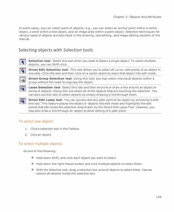
Chapter 3: Objects And Attributes
In some cases, you can select parts of objects; e.g., you can select an anchor point within a vectorobject, a word within a text object, and an image area within a paint object. Selection techniques forvarious types of objects are described in the drawing, text editing, and image editing sections of themanual.
Selecting objects with Selection tools
Selection tool: Select this tool when you need to Select a single object. To select multipleobjects, you can Shift-click.
Direct Edit Selection tool: This tool allows you to select all curve- edit points of an object inone step. Click this tool and then click on a vector object to place that object into edit mode.
Direct Group Selection tool: Using this tool, you may select individual objects within agroup without the need to ungroup the object.
Lasso Selection tool: Select this tool and then encircle or draw a line around an object orseries of objects. Doing this will select all of the objects that are touching the selection. Youcan also use this tool to select objects by simply drawing a line through them.
Direct Edit Lasso tool: You can quickly edit any path point of an object by enclosing it withthis tool. This feature places the object or objects into edit mode and highlights the editpoints that fall inside the selection area drawn by the Direct Edit Lasso Tool. Likewise, youmay also draw a line through an object to allow editing of a path point.
To select one object:
1. Click a selection tool in the Toolbox.
2. Click an object.
To select multiple objects:
Do one of the following:
Hold down Shift, and click each object you want to select.
Hold down the right mouse button and click multiple objects to select them.
With the Selection tool, drag a selection box around objects to select them. Canvasselects all objects inside the selection box.
159
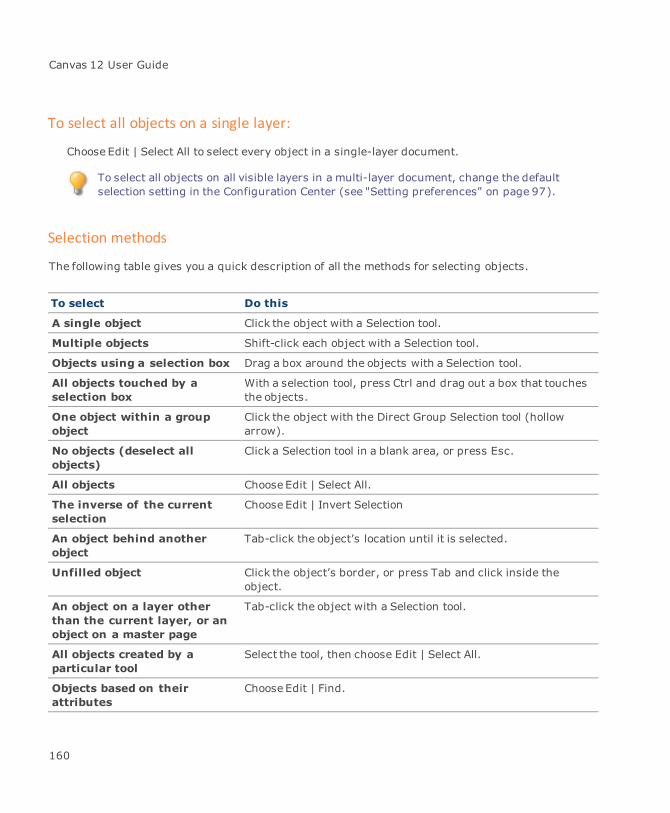
Canvas 12 User Guide
To select all objects on a single layer:
Choose Edit | Select All to select every object in a single-layer document.
To select all objects on all visible layers in a multi-layer document, change the defaultselection setting in the Configuration Center (see "Setting preferences" on page 97).
Selection methods
The following table gives you a quick description of all the methods for selecting objects.
To select Do this
A single object Click the object with a Selection tool.
Multiple objects Shift-click each object with a Selection tool.
Objects using a selection box Drag a box around the objects with a Selection tool.
All objects touched by aselection box
With a selection tool, press Ctrl and drag out a box that touchesthe objects.
One object within a groupobject
Click the object with the Direct Group Selection tool (hollowarrow).
No objects (deselect allobjects)
Click a Selection tool in a blank area, or press Esc.
All objects Choose Edit | Select All.
The inverse of the currentselection
Choose Edit | Invert Selection
An object behind anotherobject
Tab-click the object’s location until it is selected.
Unfilled object Click the object’s border, or press Tab and click inside theobject.
An object on a layer otherthan the current layer, or anobject on a master page
Tab-click the object with a Selection tool.
All objects created by aparticular tool
Select the tool, then choose Edit | Select All.
Objects based on theirattributes
Choose Edit | Find.
160
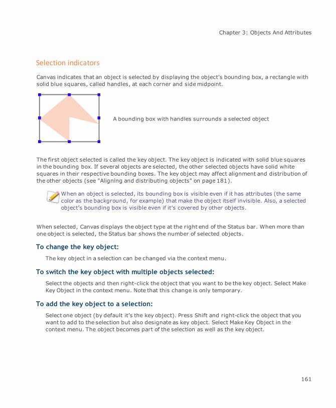
Chapter 3: Objects And Attributes
Selection indicators
Canvas indicates that an object is selected by displaying the object’s bounding box, a rectangle withsolid blue squares, called handles, at each corner and sidemidpoint.
A bounding box with handles surrounds a selected object
The first object selected is called the key object. The key object is indicated with solid blue squaresin the bounding box. If several objects are selected, the other selected objects have solid whitesquares in their respective bounding boxes. The key object may affect alignment and distribution ofthe other objects (see "Aligning and distributing objects" on page 181).
When an object is selected, its bounding box is visible even if it has attributes (the samecolor as the background, for example) that make the object itself invisible. Also, a selectedobject’s bounding box is visible even if it’s covered by other objects.
When selected, Canvas displays the object type at the right end of the Status bar. When more thanone object is selected, the Status bar shows the number of selected objects.
To change the key object:
The key object in a selection can be changed via the context menu.
To switch the key object with multiple objects selected:
Select the objects and then right-click the object that you want to be the key object. Select MakeKey Object in the context menu. Note that this change is only temporary.
To add the key object to a selection:
Select one object (by default it’s the key object). Press Shift and right-click the object that youwant to add to the selection but also designate as key object. Select Make Key Object in thecontext menu. The object becomes part of the selection as well as the key object.
161
Canvas 12 User Guide
Editing objects
All types of objects in Canvas can be easilymodified. In general, you place an object in edit mode tomodify it.
Edit mode lets you use various features to edit each type of object; e.g., when a text object is in editmode, use word-processing features to select, cut, copy, paste, and edit text. When a vector objectis in edit mode, you can modify anchor points and segments to reshape its path. When a paint objectis in edit mode, you can use painting tools and commands tomodify the image it contains.
Some other objects, including spirals, EasyShapes, objects that have transparencymasks, andSpriteEffects, have special editing modes (besides their standard edit modes); e.g., if you place avector object in edit mode, you can edit the object’s path. If the object also has a transparency mask,you can edit its path in path edit mode, or use the Sprite tool to edit its transparencymask in maskedit mode.
To place objects in edit mode:
Select an object and choose Object | Edit | Object to place it in object edit mode or double-clickthe object.
To exit edit mode:
Press the Esc key.
Selecting and editing objects with the context menu
Use the context menu to select an object or place an object in edit mode. The context menu can makeit easier to select and edit objects that are covered by other objects.
To display the context menu:
Right-click the object.
To select objects using the context menu:
1. When no objects are selected or in edit mode, point to the object you want to select. If theobject is hidden behind other objects, point to its location.
2. ChooseSelect | Object Name in the context menu. Canvas selects the object whose name youchoose in the Select submenu. Choose a vector, text, paint, or group object.
162
Chapter 3: Objects And Attributes
To edit objects using the context menu:
1. When no objects are selected or in edit mode, point to the object you want to edit. If theobject is hidden behind other objects, point to its location.
2. Choose Edit | Object Name in the context menu. Canvas places the object whose name youchoose in the Edit submenu into edit mode. Choose a vector, text, or paint object.
Selecting objects based on their properties
To select an object based on its properties:
1. Choose Edit | Find to select objects by type and attributes.
2. Click the Objects tab to set up selection criteria.
Find Palette Options tab
Type Choose an object type icon in themenu. Selecting text or paint objectsmakes Fill, Stroke, and Pen options unavailable.
Fill Choose the fill ink in themenu. Only inks used in the document, plusprocess colors and white, appear in the menu.
Pen Choose the pen in themenu.
Stroke Choose the stroke in the menu. Only strokes used in the documentappear in themenu.
Object Name Type the name in the text box. Select Object # and type a number in thebox to select an object by its number.
SpriteLayers Use this option to select objects that have transparency effects.
SpriteEffects Use this option to select objects (including lenses) that haveSpriteEffects.
Lens Objects Use this option to select objects that have been converted to lenses.
Group Level Select a value from the menu if you wish to search in grouped objects.
Search all visiblelayers
To select objects in the current layer only, uncheck this option.
Add result toselection
Check to select additional objects without deselecting objects that arealready selected.
Use Selected Object’sAttributes
When an object is selected, select this option to enter the object’sproperties in the Objects tab.
Grab Attributes Click to select objects based on the current settings.
163
Canvas 12 User Guide
Using selection sets
Click the arrows to expand the palette to work with selection sets, which let you broaden a search.
Selection criteria symbols make up a selection set. The current selection set is boxed. Changingselection options updates this selection set. Click a set to make it the current selection set.
Or: Click to create an empty selection set.
Copy: Click to duplicate the current selection set.
Clear: Click to delete the current selection set. With only one set, Clear is unavailable.
Copying, cutting, pasting, and deleting objects
Once you select one or more objects, you can perform various basic editing functions. The followingare the basic editing commands in the Edit menu:
Command Result
Copy Copies a selection to the Clipboard
Cut Removes a selection and places it on the Clipboard
Clear Removes a selection without changing the Clipboard
Duplicate Copies a selection into the same document without changing theClipboard
Duplicate withTransform
Creates copies of objects that have been skewed, rotated, or offset.
Paste Places the Clipboard contents into the active document
Paste and Place Places the Clipboard contents into the active document with the upper-left corner at the point where you click
Copying objects to the Clipboard
The Clipboard is a part of the system that temporarily stores selected objects when you choose theCopy or Cut command. The Clipboard stores the results of one editing action (which can includemultiple objects). Whatever is on the Clipboard is replaced by the next selection you place there,including a selection placed by using the Cut or Copy command in another application.
You can bypass the Clipboard by using the Duplicate command to quickly copy a selectedobject in the same document without replacing the Clipboard contents.
164
Chapter 3: Objects And Attributes
Using the Clear command or the Delete keyboard key does not replace the contents of theClipboard.
When you paste objects into other programs, the Clipboard uses a format that the receiving programunderstands. However, special types of objects and special object attributes can be lost whenpasting objects into other applications. If you can’t transfer an object successfully using theClipboard, consider using a compatible file format to import the object as a file into other programs.
Using Cut, Copy, and Paste commands
The Cut, Copy, and Paste commands let you make copies of objects using the Clipboard. Use Cut orCopy to place objects on the Clipboard, and then choose Paste to place copies in the same document,other open Canvas documents, and also into other programs.
You select one or more Canvas objects before choosing Cut or Copy. You can select text objects, paintobjects, vector objects, specialized objects such as dimensions, and group objects. When youchooseCut or Copy, the selected items appear on the Clipboard.
The Cut command removes selections from the document.
The Copy command leaves selections in the document.
Using the Paste command to insert the Clipboard contents into a document does not erase theClipboard. You can use Paste to insert the Clipboard contents as many times as you want. TheClipboard contents remain intact until you use the Copy or Cut command in any application to replacethe Clipboard contents with a new selection.
To paste copied objects:
1. Select the objects that you want to copy.
2. Choose Edit | Copy. Canvas puts the selected objects on the Clipboard.
3. If you want to paste the copied selection into another document, switch to that document.You can switch to an open Canvas document by choosing its name at the bottom of theWindowmenu.
4. Choose Edit | Paste. Canvas pastes the Clipboard contents into the active document. Pastedobjects appear selected in the center of the document window.
Options for copying objects
The Copy Options dialog box lets you select formats when you copy objects to the Clipboard. Thiscommand is useful when you want to copy a selection using a format that can be pasted into anotherprogram.
165
Canvas 12 User Guide
These options have no effect when you paste selections in Canvas.
You can select the program into which you want to paste objects. Canvas selects the best format forcopying the selection to the Clipboard. You can select common programs, such as Microsoft Word,Microsoft PowerPoint, and Microsoft Excel.
To use Copy options:
1. Select the items to copy and choose Edit | Copy Special | Copy Options.
2. Select options in the dialog box.
3. Click OK and Canvas will copy the selection to the Clipboard.
Copy options
Preset for Choose a program name. This sets up the dialog box so objects will becopied in the best format for pasting into the selected program. If theprogram you want to use is not listed, use the other options to select theformat for copying objects to the Clipboard.
Copy vector object(s) Uses the standard format to copy objects to the clipboard in Windows(WMF). In most cases, this option is the same as using the standardCopy command. WMF does not support transparency; transparentCanvas objects are not rendered and will appear opaque when pastedinto other programs.
Copy as image Copies objects to the Clipboard as images.
Resolution Select a resolution option, or select Other and enter the desiredresolution. This option preserves transparency effects among Canvasobjects. However, most programs don’t support transparency, soCanvas objects pasted into other programs won’t appear transparentrelative to objects in the other programs.
Anti-Alias Softens the edges of objects copied to the Clipboard. Anti-Alias isavailable when you select Copy as Image.
Copy as 96 dpi Select this check box to copy the object at 96 dpi.
Use Settings for CopyCommand
Applies the dialog box settings to the Copy command. When you selectthis option, you don’t have to choose Edit | Copy Special | Copy Optionsto use the same settings again.
166

Chapter 3: Objects And Attributes
Copy special commands
Several commands let you perform special operations for copying objects to the Clipboard. To viewthese commands, choose Edit | Copy Special.
Copy as image
When you want to copy an object, and then paste it into a document created in another application,use the Copy as Image command to enhance the printed appearance of the Canvas object you intendto paste. This procedure can smooth out jagged edges and help maintain the object’s details.
To use the Copy as Image command:
1. Select the objects you want to copy.
2. Choose Edit | Copy Special | Copy as Image.
Canvas places the selected objects on the Clipboard.
3. Use another application’s Paste command to place the Clipboard contents into a document.
Copy at 4X, Copy at 8X
Use the Copy at 4X command or Copy at 8X command to place vector objects on the Clipboard asobjects at specific resolution levels. You might want to do this if you are pasting Canvas vectorobjects into another program and the objects appear jagged when printed. This can happen when aprogram prints Canvas vector objects at the low resolution of the screen display.
When copying and pasting within Canvas documents, these commands perform the samefunction as the standard Copy command. Using these commands is not recommended forcopying paint objects, which are already at a specific resolution.
The Copy at 4X and Copy at 8X commands place selected objects on the Clipboard at specificresolution levels: “4X” indicates resolution 4 times greater than screen resolution and “8X” indicatesresolution 8 times greater than screen resolution. 4X approximates the resolution of a 300 dpiprinter; 8X approximates the resolution of a 600 dpi printer. Choose the resolution level based on theprinting device you are going to use.
To copy vector objects at increased resolution:
1. Select the objects to copy.
2. Choose Edit | Copy Special | Copy At 4X or Edit | Copy Special | Copy at 8X.
167

Canvas 12 User Guide
Canvas places the selected objects on the Clipboard.
3. Paste the Clipboard contents into other applications.
Copying selections in objects
Besides using Cut or Copy to place entire objects on the Clipboard, use these commands to placeselected parts of Canvas objects on the Clipboard.
Cut or copy the following parts of objects:
Text selections made by highlighting text in a text object.
Image selections made by defining areas, ranges of colors, or loading alpha channels in apaint object.
Segment selections made by selecting anchor points of vector objects in path edit mode.
Pasting selections and pasting into objects
When you paste a selection, the result depends on whether an object is in edit mode at the time:
Pasting with no object in edit mode creates a new, separate object containing the selection.
Pasting with an object in edit mode usually pastes the selection into the object.
For example, if you copy a highlighted text selection, and then choose Paste when no object is inedit mode, you create a new text object containing only the text you selected. If you choosePastewhen a text object is in edit mode, the pasted text appears at the insertion point in the textobject. If you choose Paste when a paint object is in edit mode, the selected text appears as afloating image selection in the paint object.
Pasting into text: You can paste text into a text object in edit mode. This lets you insertnew text cut or copied from another object, and move text from one place to another whileediting a text object.
Pasting pixels into images: You can paste an image selection into a paint object in editmode. The pixels that you paste become a floating selection in the paint object.
Pasting objects into images: You can paste a vector object or text into a paint object inedit mode. Canvas converts the object into pixels pasted as a floating selection in the paintobject.
Pasting and placing objects: You can use the Paste and Place command to copy objectsand position the copies anywhere in the document. Copy the objects to be pasted. Press Ctrl
168
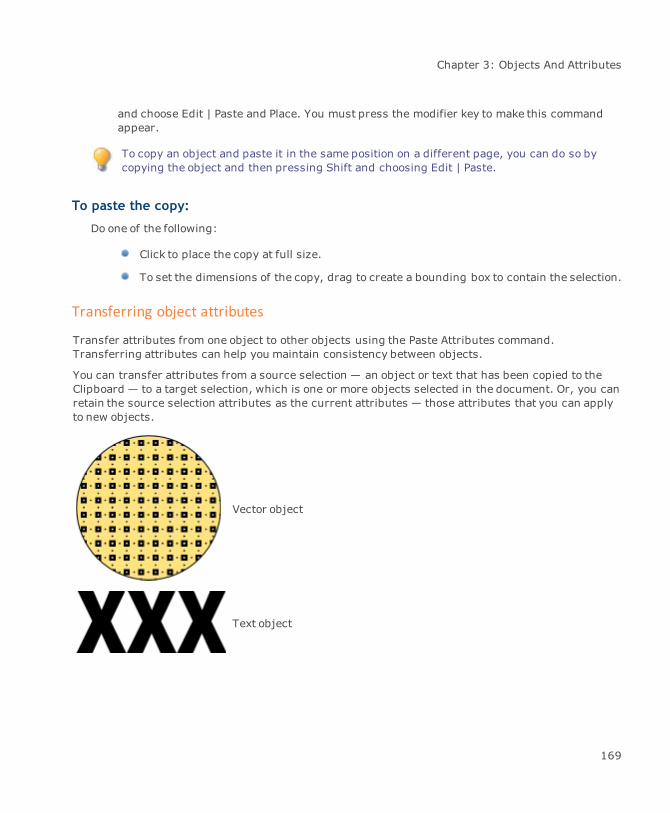
Chapter 3: Objects And Attributes
and choose Edit | Paste and Place. You must press the modifier key to make this commandappear.
To copy an object and paste it in the same position on a different page, you can do so bycopying the object and then pressing Shift and choosing Edit | Paste.
To paste the copy:
Do one of the following:
Click to place the copy at full size.
To set the dimensions of the copy, drag to create a bounding box to contain the selection.
Transferring object attributes
Transfer attributes from one object to other objects using the Paste Attributes command.Transferring attributes can help you maintain consistency between objects.
You can transfer attributes from a source selection — an object or text that has been copied to theClipboard — to a target selection, which is one or more objects selected in the document. Or, you canretain the source selection attributes as the current attributes — those attributes that you can applyto new objects.
Vector object
Text object
169
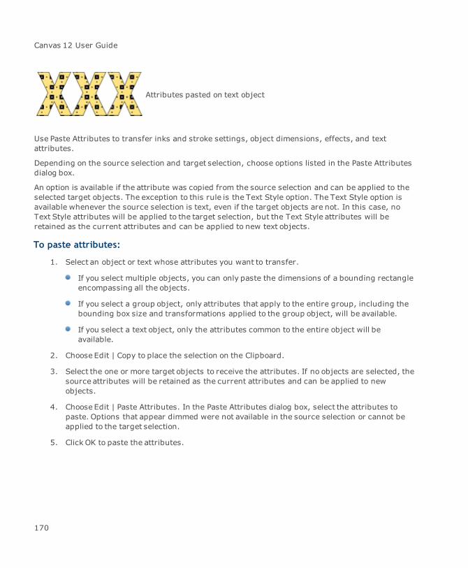
Canvas 12 User Guide
Attributes pasted on text object
Use Paste Attributes to transfer inks and stroke settings, object dimensions, effects, and textattributes.
Depending on the source selection and target selection, choose options listed in the Paste Attributesdialog box.
An option is available if the attribute was copied from the source selection and can be applied to theselected target objects. The exception to this rule is the Text Style option. The Text Style option isavailable whenever the source selection is text, even if the target objects are not. In this case, noText Style attributes will be applied to the target selection, but the Text Style attributes will beretained as the current attributes and can be applied to new text objects.
To paste attributes:
1. Select an object or text whose attributes you want to transfer.
If you select multiple objects, you can only paste the dimensions of a bounding rectangleencompassing all the objects.
If you select a group object, only attributes that apply to the entire group, including thebounding box size and transformations applied to the group object, will be available.
If you select a text object, only the attributes common to the entire object will beavailable.
2. Choose Edit | Copy to place the selection on the Clipboard.
3. Select the one or more target objects to receive the attributes. If no objects are selected, thesource attributes will be retained as the current attributes and can be applied to newobjects.
4. Choose Edit | Paste Attributes. In the Paste Attributes dialog box, select the attributes topaste. Options that appear dimmed were not available in the source selection or cannot beapplied to the target selection.
5. Click OK to paste the attributes.
170
Chapter 3: Objects And Attributes
Paste Attributes options
Pen ink Transfers the source selection’s pen ink. You can transfer pen inks if thesource selection is a vector object or text that has a pen ink, and thetarget objects are vector or text objects.
Fill ink Transfers the source selection’s fill ink. You can transfer fill inks if thesource selection is a vector object or text that has a fill ink, and thetarget objects are vector or text objects.
Stroke Transfers the source selection’s stroke, including pen, dash, and arrowattributes. You can transfer strokes if the source selection is a vectorobject or text that has a stroke, and the target objects are vector or textobjects.
Dimensions Transfers the dimensions of a rectangle “bounding box” thatencompasses the source selection. You can transfer bounding boxdimensions from any source object to any selected objects, but not totext selected within a text object. This makes all target objects the samesize as the source.
If the source object has been rotated or skewed, you can transfer itsoriginal dimensions by selecting Dimensions. To transfer itstransformed dimensions, select Transform.
Transform Transfers rotation and skewing applied to the source selection’sbounding box. You can transfer these effects to any selected objects.
Transparency Transfers the transparency effects applied to the source selection.
Text Style Transfers certain text attributes from a text source selection to a texttarget selection: font, type size, text style (bold, italic, and so on),leading, kerning, and justification. You can transfer text attributes whena particular attribute is uniform in the source selection; e.g., if differentkerning values are applied to characters in the source text, kerning willnot be available for transfer to the target text.
SpriteEffects Transfers filters and adjustments that have been applied with theSpriteEffects palette from the source to the target objects.
Making multiple copies
Use the Copy and Paste commands tomake multiple copies of selected objects through the Clipboard.If you want more control over placement, number of copies, scaling or rotation, use the Duplicate andReplicate commands tomake multiple copies.
171

Canvas 12 User Guide
With a selection on the Clipboard, choose Paste to insert the selection in the center of theactive document’s current view. Repeat the Paste command to makemultiple copies.
The Duplicate command copies selections immediately and lets you space copies evenly. TheReplicate command lets you scale, rotate, and offset multiple copies.
Duplicating selections
The Duplicate command quickly copies selected objects into the same document, without affectingthe contents of the Clipboard.
The Duplicate command offsets copies a preset distance horizontally and vertically from the original.You can move the copy (without deselecting it) to adjust the offset distance and direction and thenrepeat the Duplicate command to makemore evenly-spaced copies.
You can change the Duplicate command’s preset offset values (see "Setting preferences" on page97).
To duplicate and space copies evenly:
1. Select one or more vector, text, paint, or group objects to copy.
2. Choose Edit | Duplicate. Canvas duplicates the selection and offsets the copy a presetdistance from the original.
3. The copy must remain selected as you drag it or use the keyboard arrow keys tomove it intoposition. The new position establishes the offset distance and direction from the originalselection.
4. Choose Edit | Duplicate again. Canvas creates the next copy using the offset defined from theoriginal selection to the first copy. Repeat this step to create additional evenly-spaced copies.
172

Chapter 3: Objects And Attributes
Canvas offsets and stacks duplicates, placingthe newest copy in front of the stack.
Duplicated objects are offset a presetamount (gray circles). By moving the firstcopy and repeating Duplicate, you can set acustomoffset distance and direction (lightgray circles).
To duplicate selected objects with modifier key:
You can duplicate an object by pressing a modifier key as you drag the object. When an object isselected, press a modifier key to duplicate and resize it as you drag a handle. In Freeformmode, youcan press a modifier key to duplicate while rotating or skewing an object.
1. Select the objects you want to duplicate.
2. Press Ctrl as you drag the objects.
To make multiple copies while dragging:
Select the objects you want to duplicate. Press Ctrl+Alt as you drag the objects.
To duplicate while resizing:
1. Select an object to duplicate.
2. Begin to drag a handle on the object’s bounding box to the size you want the duplicate to be.
173

Canvas 12 User Guide
3. As you drag, press and hold Ctrl. When you release the mouse button and the modifier key,the duplicate object appears in front of the original.
To duplicate while rotating or skewing:
1. Select an object and choose Effects | Freeform to put the object in Freeformmode.
2. Point to a handle and press Ctrl as you drag the handle.
To rotate the object: Drag one of the four corner handles.
To skew the object horizontally: Drag a horizontal skew handle to the left or right.
To skew vertically: Drag a vertical skew handle up or down.
The duplicated object rotates or skews depending on which handle you drag. You cannot rotate andskew the object at the same time. When you release the mouse, the duplicate is in front of theoriginal.
Duplicate with Transform
You can now create duplicates of objects that have been skewed, rotated, or offset.
1. Select the original object.
2. Duplicate the object.
3. Select the duplicate and apply a transformation, such as rotation, to the duplicate object.
4. Choose Edit | Duplicate with Transform.
The duplicate object is then duplicated as well as transformed.
Remember that each time you choose Edit | Duplicate with Transform, the duplicate object isduplicated and transformed once again; e.g., duplicate an object and then rotate the duplicate by20°. Choose Duplicate with Transform and the new duplicate is transformed by another 20°.
Themultigon on the left was duplicated and thenrotated 20°. Each time Duplicate with Transformwas applied, the resulting duplicate wouldrotate an additional 20°. The final duplicate hada rotation of 200°.
174

Chapter 3: Objects And Attributes
To create multiple duplicates:
After you duplicate an object using a modifier key, make more copies with the same offset distance,angle of rotation, or skew factor.
1. Select the duplicated object.
2. Choose Edit | Duplicate. Canvas creates another duplicate and applies the same offsetdistance, angle of rotation, or skew factor.
Scaling, rotating, and offsetting copies
The Replicate command offers powerful capabilities for duplicating objects. Use the Replicate dialogbox to set the number of copies and to rotate, scale, and position copies with one command.
To replicate a selection:
1. Select one or more objects to copy and choose Edit | Replicate.
2. In the Replicate dialog box, specify the number of copies. Enter the scaling, rotation, andoffset values you want to apply. For information on these settings, see "Replicate options" onpage 176.
To preview the replication: Click Apply. Canvas draws the copies and the dialog boxstays open. You can change settings and click Apply to preview the new settings.
To cancel the replication: Click Cancel. Canvas closes the Replicate dialog box anderases preview copies.
3. Click OK to copy the selection and close the Replicate dialog box. The original object isdeselected and the copies are selected.
175

Canvas 12 User Guide
Replicate options
Copies Enter the number of objects you want to create.
Rotate To rotate each copy relative to the preceding object, select Rotate. Typethe rotation amount from (minus) -359.0 to 359.0 degrees. The centerof rotation is shown in the “Around” box by a hollow handle; click toselect another handle as the rotation center.
Scale by To incrementally change the size of each copy, select Scale by. In thepop-up menu, choose Percentage, Length, or Ratio. In the text boxes,enter horizontal and vertical scaling factors.
Percentage scales each copy by the specified percentages of theproceeding object’s dimensions. Enter whole numbers from 1% to999%.
Ratio lets you resize copies by fractional amounts. Canvas scales eachcopy to ratios of the previous object’s horizontal and verticaldimensions.
Type ratios with whole numbers from 1 to 999. The left numberrepresents the copy; the right number represents the previous object. A1/1 ratio maintains dimensions; 1/2 halves dimensions; 2/1 doublesdimensions.
Length increases or decreases by a fixed amount each copy of the objectusing the values in the horizontal and vertical text boxes.
Proportional If selected, Canvas makes the vertical value in the Scale by or Offset areaequal to the horizontal value.
Offset Check this option to place copies a specified distance from the previousobject. In the text boxes, enter the horizontal and vertical offsetdistance. Positive numbers offset copies up and right; negative numbersoffset objects down and left.
Object data Displays the selection’s height and width. These values can’t be edited.
To replicate and position objects:
You can replicate objects and then strategically position them according to specified X/Ycoordinates.
To replicate and position an object:
Select an object and then choose Edit | Replicate and Position.
176

Chapter 3: Objects And Attributes
Replicating and positioning options
Coordinate space The Length radio button must be selected to position objects accordingto X/Y coordinates. To enable the Angular radio button, you must firstconfigure your world with the GIS palette (see GIS palette).
Bounding box icon Canvas performs the positioning according to the selected handle. Bydefault, the center handle is selected. Select another handle, ifnecessary.
Coordinate table Enter the X/Y coordinates in the appropriate fields. The # column liststhe replicates in sequence.
Position originalobject
If selected, the coordinates for the first replicate correspond to theoriginal object; i.e., the original object will move to the coordinatesentered for replicate #1.
Menu icon Click to access the Paste and Load commands.
Paste: Paste points that have been copied to the Clipboard.
Load: Open .txt, .csv (comma delimited), and .prn (space delimited)files that contain points.
Grouping and ungrouping objects
Use the Group command to unite objects that you want to keep together as one unit. You can groupindividual objects as well as already-grouped objects. When you no longer want to keep a grouptogether, separate the original objects with the Ungroup command.
When you apply a command to a group object, the effect in most cases is the same as if you appliedthe command to each object in the group individually.
To group objects:
1. Select the objects that you want to group.
2. Do one of the following:
ChooseObject | Group.
In the Properties bar, click the Group button.
Canvas replaces the bounding boxes of the individual objects with a single bounding box.
177

Canvas 12 User Guide
After you group objects, you can select individual objects in the group with the DirectSelection tool.
To ungroup objects:
1. Select one or more grouped objects that you want to separate.
2. Do one of the following:
ChooseObject | Ungroup.
In the Properties bar, click the Ungroup button.
Canvas separates the group and leaves the individual objects selected. If any of theseobjects are group objects, you can ungroup them by choosing Object | Ungroup again.
Grouping and stacking order
Grouping objects can change the stacking order of the objects relative to objects outside the group;e.g., you have three overlapping objects. If you group the front and back objects, the group moves tothe back and the middle (not grouped) object becomes the front-most object.
The square is behind the triangle, which is behind the circle in thestacking order
After selecting the square and circle and grouping them, the group goesbehind the triangle in the stacking order
Moving objects
Move objects by dragging them, using the Properties bar, or using the keyboard arrow keys. You canalso use the Move command to specify a position change, and the Object Specs palette to specify
178
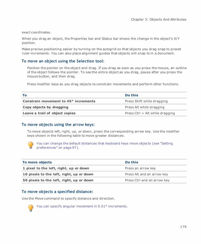
Chapter 3: Objects And Attributes
exact coordinates.
When you drag an object, the Properties bar and Status bar shows the change in the object’s X/Yposition.
Make precise positioning easier by turning on the autogrid so that objects you drag snap to presetruler increments. You can also place alignment guides that objects will snap to in a document.
To move an object using the Selection tool:
Position the pointer on the object and drag. If you drag as soon as you press themouse, an outlineof the object follows the pointer. To see the entire object as you drag, pause after you press themouse button, and then drag.
Press modifier keys as you drag objects to constrain movements and perform other functions.
To Do this
Constrain movement to 45° increments Press Shift while dragging
Copy objects by dragging Press Alt while dragging
Leave a trail of object copies Press Ctrl + Alt while dragging
To move objects using the arrow keys:
Tomove objects left, right, up, or down, press the corresponding arrow key. Use the modifierkeys shown in the following table tomove greater distances.
You can change the default distances that keyboard keys move objects (see "Settingpreferences" on page 97).
To move objects Do this
1 pixel to the left, right, up or down Press an arrow key
10 pixels to the left, right, up or down Press Alt and an arrow key
50 pixels to the left, right, up or down Press Ctrl and an arrow key
To move objects a specified distance:
Use the Move command to specify distance and direction.
You can specify angular movement in 0.01° increments.
179

Canvas 12 User Guide
1. Select the objects and then choose Object | Move.
2. In the Move dialog box, enter values to move the object horizontally or vertically, or to changethe angle. Use negative numbers tomove up and to the left. Use positive numbers to movedown and to the right.
3. Click Apply to preview or OK to implement the Move settings.
Arranging objects in the stacking order
Each object in a Canvas document is part of a stack of objects on the same layer. Each object has aposition in the stack. Unless you rearrange objects, the newest object, created or pasted, is in frontof the stack and the oldest object in the back.
Stacking order affects the appearance of objects when you view and print them. Like actual objectsplaced in a stack, the front object in the stack blocks objects behind it. An object’s position in thestack also is a factor in alignment and combining operations.
Commands in the Object | Arrange menu let you change an object’s position in the stack. Moveobjects to the front or back, and move objects one level at a time toward the front or back of thestack.
To change an object’s position in the stack:
Select the object and choose a command in the Object | Arrange menu.
Command Result
Bring to Front Moves selected objects to the front of the stack
Send to Back Moves selected objects to the back of the stack
Shuffle Up Moves selected objects one step toward the front
Shuffle Down Moves selected objects one step toward the back
Arranging objects on layers and pages
Commands in the Object | Arrange menu let you move and copy selected objects to other layers onthe same page and to layers on other pages.
The destination layer for the objects cannot be locked.
180
Chapter 3: Objects And Attributes
To send or copy objects to another location:
1. Select the objects, and then do one of the following:
ChooseObject | Arrange | Send to Layers tomove objects to new locations.
ChooseObject | Arrange | Copy to Layers to copy objects to new locations.
2. In the Layer Select dialog box, click one or more layers to designate them as the destinationfor the selected objects.
3. Click Select. Canvas copies or moves the selected objects to the destination layer or layers.
Locking and unlocking objects
When you want to secure objects from unintentional changes, you can lock them. Once an object islocked, it can only be selected by Tab-clicking the object. However, if the “Canvas 6-style objectlocking” option in the Configuration Center is selected, you can select locked objects by clicking onthem. Locked objects can be copied, but the copies won’t be locked.
To lock or unlock objects:
1. Select the objects that you want to lock or unlock.
2. ChooseObject | Lock or Object | Unlock (Unlock All, if no objects are selected).
How commands affect locked objects
If you apply the Align command to several selected objects, and one object is locked, the otherobjects align to the locked object.
If you group several objects and one of the objects is locked, all the objects are positioned behind thelocked object in the stacking order.
Aligning and distributing objects
In Canvas you can quickly and easily align or distribute selected objects from the Align menu, theProperties bar, or the Align palette.
To open the Align palette:
ChooseWindow | Palettes | Align.
181
Canvas 12 User Guide
To align or distribute objects:
1. Select two or more objects.
2. Do one of the following:
ChooseObject | Align, and select an alignment option.
In the Properties bar, select an alignment option.
In the Align palette, select an alignment or distribution option, then click Apply.
You can apply alignment and distribution options to vector objects, group objects, paint objects, andtext objects. You can align and distribute objects in separate or combined operations. As thereference point for alignment and distribution, you can choose points on the objects or thedocument.
Aligning objects: When aligning objects, Canvas lines up key points on the objects inrelation to the key object. Choose left, right, top, bottom, or center alignment.
Distributing objects: When distributing objects, Canvas spreads them out over a specifiedarea and equalizes the space between the key points. Choose inside, top, center, bottom, andoutside as methods for distribution; e.g., if you choose left edges for distribution, the left-most point in each object is an equal distance from the leftmost point in each of itsneighbors.
If one of the objects you select for alignment is locked, other objects align relative to it. Whendistributing objects, Canvas may place all objects relative to the option selected in the Distribute tomenu.
182

Chapter 3: Objects And Attributes
Align palette
Vertical Align:
NoneTopCenterBottomEdge to Edge (Top to Bottom)Edge to Edge (Bottom to Top)
Distribute:
Inside
183
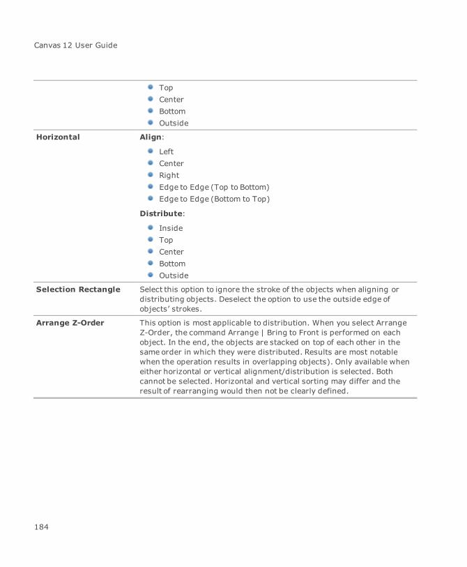
Canvas 12 User Guide
TopCenterBottomOutside
Horizontal Align:
LeftCenterRightEdge to Edge (Top to Bottom)Edge to Edge (Bottom to Top)
Distribute:
InsideTopCenterBottomOutside
Selection Rectangle Select this option to ignore the stroke of the objects when aligning ordistributing objects. Deselect the option to use the outside edge ofobjects’ strokes.
Arrange Z-Order This option is most applicable to distribution. When you select ArrangeZ-Order, the command Arrange | Bring to Front is performed on eachobject. In the end, the objects are stacked on top of each other in thesame order in which they were distributed. Results are most notablewhen the operation results in overlapping objects). Only available wheneither horizontal or vertical alignment/distribution is selected. Bothcannot be selected. Horizontal and vertical sorting may differ and theresult of rearranging would then not be clearly defined.
184

Chapter 3: Objects And Attributes
Align to Choose a reference for alignment:
Key Selection Object: Aligns all the objects in relation to the keyselection object. Key selection object does not move.Grid: Aligns all objects to the grid. If no grid is defined, the objectsdon’t move. The key selection object has no effect.Printable Area: Aligns all objects with the edge of printable area.If no printable area is defined, the entire document is selected.Document: To a specified location in the document. If you centeran object in a multi-page illustration, portions can appear onmultiple tiles.
Distribute to Choose a reference for distribution:
Selection Bounds: Distributes all the objects over the areadefined by current selection bounds. Key selection object maymove.Printable Area: Distributes all objects with the edge of printablearea. If no printable area is defined, the entire document isselected.Document: Distributes all objects over the entire area of thedocument. Key selection object maymove.Fixed Amount: Distributes all objects over a fixed distance. Keyselection object doesn’t move and remaining objects are positionedaccordingly within that distance. Enter the amount in the Horizontaland Vertical fields below the Distribute tomenu.Spacing: Distributes all objects so the distance between eachobject is the amount indicated in the Vertical and Horizontal fieldsbelow the Distribute to menu. The key selection object doesn’tmove and the remaining objects are positioned accordingly. Theamount of spacing may be a negative number.
When applying either horizontal or vertical edge-to-edge alignment, the order of the alignedobjects depends on the order in which the objects were created; i.e., the object furthest tothe left or at the very top in an edge-to-edge alignment was created first. Both Edge to Edgeoptions have the same effect. They align all the remaining objects edge to edge with the keyselection object.
185

Canvas 12 User Guide
Rotating, skewing, and flipping objects
You can rotate Canvas objects clockwise or counter-clockwise, flip them on one or both axes, andskew their bounding boxes. Rotate and skew around an object’s center, or move the centerpoint toany location.
When you rotate an object, the object’s bounding box also rotates. If you drag a selection handle of arotated object, the bounding box changes shape in the rotated orientation, so you can resize anobject without distorting its basic shape.
To remove effects:
After you rotate, skew, or flip objects, you can return them to their original orientation and shape.
Select the objects and choose Effects | Remove Effects.
To return the rotated bounding box to its original orientation:
Choose Path | Convert To Paths.
Rotating and skewing in freeform mode
When you put an object in freeformmode, you can rotate and skew it by dragging special handles.
To put an object in freeform mode:
Select the object and choose Effects | Freeform. Rotation and skewing handles and the object’scenterpoint appear.
You can also put a selected object in freeformmode by clicking it. This depends on a setting in theConfiguration Center (see "Setting preferences" on page 97).
To end freeform mode:
Click away from the object, or press Esc.
Rotating objects in freeform mode
In freeformmode, the circular handles at each corner of the bounding box are rotation handles. Thecircle and crosshair in the center of the object is the point around which the object rotates.
186

Chapter 3: Objects And Attributes
To rotate an object in freeform mode:
Drag one of the four corner handles. An outline of the object rotates as you drag a handle.
To set the center of rotation:
Drag the centerpoint to a new location anywhere on the screen. Tomake the centerpoint snap toone of the handles or the center, press Shift as you drag.
Rotating objects
If you prefer to rotate objects a specified amount, use the following commands from the Effectsmenu:
Rotate Right: Choose 90, 45, or 30°, or Other to open the Rotate dialog box and specifyrotation options.
Rotate Left: Choose 90, 45, or 30°, or Other to open the Rotate dialog box and specifyrotation options.
Horizontalize: The Horizontalize command rotates a selected object along a definedhorizontal line. This command is useful when trying to straighten image objects.
Rotate options
Direction Click the Clockwise or Anticlockwise button to set the direction ofrotation.
Center Set the center of rotation. By default the center of the object is selected.
Angle Set the angle of rotation.
Hard rotate for image Choose this option to render and rotate the background area of theimage.
Anti-alias image Select this option to have a smoother, better quality image.
187

Canvas 12 User Guide
To apply the Horizontalize command:
1. Select the object.
2. Choose Effects | Horizontalize. The cursor changes to a crosshair.
3. Click the crosshair to establish the start point of the horizontal line.
4. Click the crosshair again to indicate the end point of the horizontal line.
5. In the Rotate dialog box, select a handle in the bounding box icon to define the center ofrotation.
6. Enter the direction and angle of rotation.
7. Click Apply to see the effect and then OK to close the dialog box.
Skewing objects in freeform mode
When an object is in freeformmode, slant its shape by dragging the horizontal and vertical skewhandles. Skewing an object reshapes it by changing the relationship of the horizontal and verticalaxes to the skew centerpoint.
Canvas skews objects around a centerpoint that you can position to achieve the desired effect. Dragthe centerpoint to any position inside or outside the object. The location of the skew centerpointchanges the effect of dragging a skew handle on the object.
You can also skew objects by clicking the Skew button in the Properties bar. Select a skewoption, then enter a degree value in the field, and press Enter.
To position the centerpoint on one of the freeform handles or in the center of the object, Shift-dragthe centerpoint to place it.
To skew an object horizontally:
Drag a horizontal skew handle to the left or right.
To skew vertically:
Drag a vertical skew handle up or down.
Transformed dimensions vs. untransformed dimensions
If you plan on transforming objects, you have the option of maintaining the object’s originaldimensions or allowing the object’s dimensions to be altered after the transformation.
Click on the Transform icon in the Properties bar and select either Transformed Dimensions orUntransformed Dimensions.
188
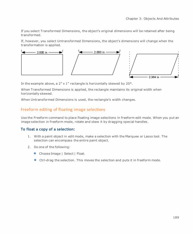
Chapter 3: Objects And Attributes
If you select Transformed Dimensions, the object’s original dimensions will be retained after beingtransformed.
If, however, you select Untransformed Dimensions, the object’s dimensions will change when thetransformation is applied.
In the example above, a 2” x 1” rectangle is horizontally skewed by 20°.
When Transformed Dimensions is applied, the rectangle maintains its original width whenhorizontally skewed.
When Untransformed Dimensions is used, the rectangle’s width changes.
Freeform editing of floating image selections
Use the Freeform command to place floating image selections in freeform edit mode. When you put animage selection in freeformmode, rotate and skew it by dragging special handles.
To float a copy of a selection:
1. With a paint object in edit mode, make a selection with the Marquee or Lasso tool. Theselection can encompass the entire paint object.
2. Do one of the following:
Choose Image | Select | Float.
Ctrl-drag the selection. This moves the selection and puts it in freeformmode.
189
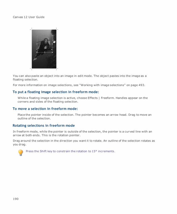
Canvas 12 User Guide
You can also paste an object into an image in edit mode. The object pastes into the image as afloating selection.
For more information on image selections, see "Working with image selections" on page 493.
To put a floating image selection in freeform mode:
While a floating image selection is active, choose Effects | Freeform. Handles appear on thecorners and sides of the floating selection.
To move a selection in freeform mode:
Place the pointer inside of the selection. The pointer becomes an arrow head. Drag tomove anoutline of the selection.
Rotating selections in freeform mode
In freeformmode, while the pointer is outside of the selection, the pointer is a curved line with anarrow at both ends. This is the rotation pointer.
Drag around the selection in the direction you want it to rotate. An outline of the selection rotates asyou drag.
Press the Shift key to constrain the rotation to 15° increments.
190
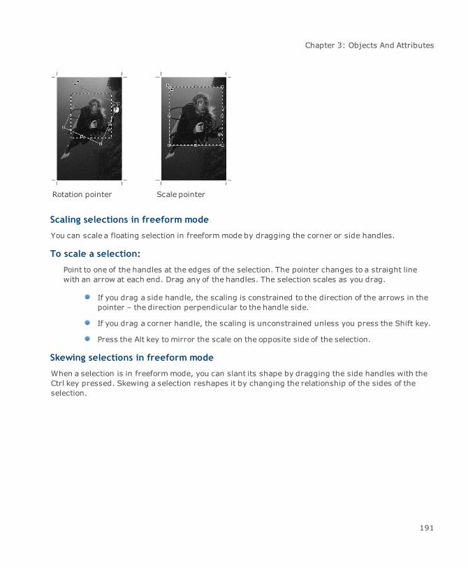
Chapter 3: Objects And Attributes
Rotation pointer Scale pointer
Scaling selections in freeform mode
You can scale a floating selection in freeformmode by dragging the corner or side handles.
To scale a selection:
Point to one of the handles at the edges of the selection. The pointer changes to a straight linewith an arrow at each end. Drag any of the handles. The selection scales as you drag.
If you drag a side handle, the scaling is constrained to the direction of the arrows in thepointer – the direction perpendicular to the handle side.
If you drag a corner handle, the scaling is unconstrained unless you press the Shift key.
Press the Alt key tomirror the scale on the opposite side of the selection.
Skewing selections in freeform mode
When a selection is in freeformmode, you can slant its shape by dragging the side handles with theCtrl key pressed. Skewing a selection reshapes it by changing the relationship of the sides of theselection.
191
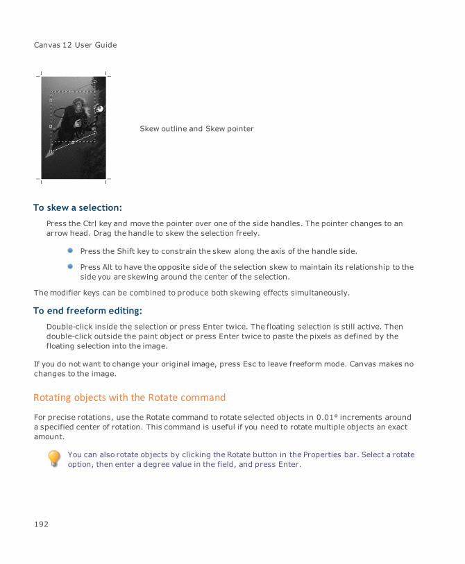
Canvas 12 User Guide
Skew outline and Skew pointer
To skew a selection:
Press the Ctrl key and move the pointer over one of the side handles. The pointer changes to anarrow head. Drag the handle to skew the selection freely.
Press the Shift key to constrain the skew along the axis of the handle side.
Press Alt to have the opposite side of the selection skew to maintain its relationship to theside you are skewing around the center of the selection.
Themodifier keys can be combined to produce both skewing effects simultaneously.
To end freeform editing:
Double-click inside the selection or press Enter twice. The floating selection is still active. Thendouble-click outside the paint object or press Enter twice to paste the pixels as defined by thefloating selection into the image.
If you do not want to change your original image, press Esc to leave freeformmode. Canvas makes nochanges to the image.
Rotating objects with the Rotate command
For precise rotations, use the Rotate command to rotate selected objects in 0.01° increments arounda specified center of rotation. This command is useful if you need to rotate multiple objects an exactamount.
You can also rotate objects by clicking the Rotate button in the Properties bar. Select a rotateoption, then enter a degree value in the field, and press Enter.
192

Chapter 3: Objects And Attributes
To rotate objects:
1. Select the object you want to rotate.
2. Choose Effects | Rotate Right/Left | Other to open the Rotate dialog box.
3. In the Rotate dialog box, click the clockwise or counter-clockwise button to choose a rotationdirection.
4. Enter the rotation angle in degrees in the Angle text box.
5. The Center edit box shows the center of rotation as a gray handle. To change it, click one ofthe black handles on the bounding box; the gray handle snaps to the new location.
6. Click Apply to preview the settings, or click OK to implement the settings and close the dialogbox.
Editing rotated objects
When you rotate an object, the object’s bounding box also rotates, so you can reshape and resize theobject in rotated space. If you drag a handle, the object’s sides keep their rotated orientation. Thisprevents distortion of the original shape.
Rotated bounding box
The bounding box of a rotated square has the same orientation asthe rotated object so the object maintains its rectangular shape,shown by the dotted lines, when you drag the bounding boxhandles.
193

Canvas 12 User Guide
Unrotated bounding box
If you choose Convert to Paths, Canvas re-orients the bounding boxof a rotated object so the object’s rectangular shape distorts whenyou drag a handle on the bounding box, as shown by the dottedlines.
Flipping objects
Flip objects horizontally, vertically, and both horizontally and vertically, with the Flip commands. Youcan flip individual objects, multiple selected objects, or grouped objects. When you flip a groupobject, objects included in the group flip around the axes of the group’s bounding box.
To flip a selected object from top to bottom:
Choose Effects | Flip | Vertical. The Vertical command flips the selection’s vertical coordinatesover its horizontal axis.
To flip a selected object from left to right:
Choose Effects | Flip | Horizontal. The Horizontal command flips the selection’s horizontalcoordinates over its vertical axis.
194

Chapter 3: Objects And Attributes
To flip a selection around both axes:
Choose Effects | Flip | Both Axes. Canvas flips the selection’s horizontal coordinates over itsvertical axis and its vertical coordinates over its horizontal axis.
Scaling objects
The Scale command provides several options for enlarging or reducing objects. Scale by apercentage or ratio, horizontally and vertically. You can also scale text and stroke weights when youscale objects.
To scale an object:
1. Select one or more objects.
2. ChooseObject | Scale to open the Scale dialog box.
3. Select the Scale options.
4. Do one of the following:
Click Apply. The object is scaled, but the dialog box remains open. If you want to changethe options you can do so and click Apply again, or you can click Cancel to discard thechanges and close the dialog box.
Click OK. The object is scaled, and the dialog box is closed.
You can also scale an entire document when you print it, without changing the objectsin the document, by specifying a scaling factor in the Print dialog box.
195
Canvas 12 User Guide
Scale options
Scale by Select a method to scale by:
Percentage: Specify vertical and horizontal percentages. Scaling anobject 150% is the same as increasing the object’s size by a factor of1.5.Ratio: Specify horizontal and vertical scaling factors as ratios byentering numbers in each set of two boxes; e.g., to scale an object toone-third its original height, enter “1” in the first text box, and “3” inthe second.
Proportional Select this check box to scale an object vertically and horizontally by thesame amount.
Keep As Group Select this check box to retain the spacing between the selected itemswhen they are scaled.
Scaling Enter the percentage of horizontal and vertical scaling.
Scale Pen Select this check box to maintain the proportion between an object’s pensize and the overall size of the object.
Scale Text If one of the selected objects contains text, select Scale Text to change thesize of the characters. Otherwise, text remains the same size.
Scaling objects by Area/Perimeter
The Scale by Area/Perimeter command lets you scale simple path objects by area or perimeter.
To scale an object:
1. Select a simple path object.
2. Do one of the following:
ChooseObject | Scale By Area/Perimeter.
Click the Scale By Area/Perimeter icon in the Properties bar.
3. Select the Scale options.
196

Chapter 3: Objects And Attributes
4. Do one of the following:
Click Apply. The object is scaled, but the dialog box remains open. If you want to changethe options you can do so and click Apply again, or you can click Cancel to discard thechanges and close the dialog box.
Click OK. The object is scaled, and the dialog box is closed.
You can also scale an entire document when you print it, without changing the objectsin the document, by specifying a scaling factor in the Print dialog box.
Scale By Area/Perimeter options
Scale by Select a method to scale by:
Percentage: Specify a percentage for scaling. Scaling an object150% is the same as increasing the object’s size by a factor of 1.5.Absolute: Specify an absolute value for scaling.
Origin Set the origin of scaling. By default the origin is the center of the object.
Area Scales the object by its area.
Perimeter Scales the object by its perimeter.
Scaling Enter the percentage of scaling or an absolute value. If you choose to scaleby absolute value, you can select the unit of measure.
Scale Pen Select this check box to maintain the proportion between an object’s pensize and the overall size of the object.
Using the Object Specs palette
The Object Specs palette provides several important features for working with objects. It displaysdata for selected objects and lets you modify settings for selected objects.
The Object Specs palette contains the following tabs:
Data: Create objects, and edit the size, position, and other data for a selected object.
Trap: Set printing options, including overprinting and trapping for color separations.
To display the Object Specs palette:
ChooseObject | Object Specs. Change coordinates, dimensions, or other settings, and then clickApply to implement them.
197

Canvas 12 User Guide
To edit an object:
Click on the Data tab to view and edit data for selected objects. The Data tab displays informationfor a selected object or group object. If you select a group object, you can change the group’ssize and coordinates, but not an individual object within the group.
When more than one object is selected, the boxes on the Data tab are not available. Youcan’t edit the position or dimensions of multiple selected objects.
1. On the Data tab, choose an object type from the Object Type drop-down.
2. Enter values for the object’s size and position in the text boxes. The type of data you canenter depends on the object type.
3. Click Apply.
Data tab settings
This tab includes object size and position data and related options. Additional options are shown fortext objects. The text options let you change the shape of a text object or change the way text wrapsin its bounding box.
Object type For a selected object, shows the object type, usually an icon of the toolthat created the object. Tomodify an object, select oval, rectangle, arc,line, or polygon.
Data type Select the type of data to display (see "Data display options" on page199).
When an object is selected, change the values in the text boxes to resizeor reposition the selected object. If Keep Proportions is checked, Canvasmaintains the proportion of the object if you change either the height orwidth.
Position data The type of data that appears in the boxes, and their labels, depends onthe selected data display option (see "Position data" on page 200).
Area Shown when Canvas can calculate the area occupied by a selectedobject’s bounding box. When you select text, the horizontal insets textbox replaces the Area text box.
Perimeter Shown when Canvas can calculate the perimeter, or distance around, aselected object’s bounding box. When you select text, the vertical insetstext box replaces the Perim text box.
Object # The object number assigned by Canvas.
198

Chapter 3: Objects And Attributes
Name Type a name for the object.
Keep Proportions Select this option to keep an object’s height and width proportional whenyou are editing the object’s dimensions.
Apply Click to apply the current settings. The Apply button changes to Createwhen no object is selected and you choose an object type to create.
Text object settings
Insets Change the proportions of a text object’s background. Type values, inpixels, in the text boxes to specify the horizontal and vertical size of thetext object’s background.
Object shape Change the shape of the text object’s background to a rectangle, roundrectangle, oval, or diamond.
Caption Select or deselect to change the way text wraps in its bounding box. Textthat is not captioned wraps to the next line based on the boundaries ofthe text’s bounding box.
You can’t use the Caption or Insets options with text that you createdusing the Path Text tool, or text that you converted to paths.
Data display options
Choose the data to display. Select Height/Width or Top/Bottom for all objects except lines. For lines,select Start/End, Delta V/H, or Length/Angle.
Height/Width: Type values in the text boxes to specify the vertical and horizontaldimensions of the object.
Top/Bottom: Type values in the text boxes to specify the position of the top, bottom, left,and right edges of the object, relative to the document rulers.
Start/End: Type values in the text boxes to specify the position of the first and lastendpoints of a line.
Delta V/H: Type values in the text boxes to specify the position of the first endpoint, andthe distance from the first endpoint to the last endpoint of the line.
Length/Angle: Type values in the text boxes to specify the position of the first endpoint,and the length and angle of the line.
199
Canvas 12 User Guide
Position data
The type of data that is displayed depends on whether you choose Height/Width or Top/Bottom,Start/End, Delta V/H, or Length/Angle.
Left: Type the horizontal distance from the ruler’s zero point to the left edge of the object.
Top: Type the vertical distance from the ruler’s zero point to the top edge of the object.
Height: Type the height of the object, relative to the top edge of the object.
Width: Type the width of the object, relative to the left edge of the object.
Bottom: Type the vertical distance from ruler’s zero point to the bottom edge of the object.
Right: Type the horizontal distance from the ruler’s zero point to the right edge of theobject.
St V: Type a value to position the first endpoint of a line, relative to the vertical ruler’s zeropoint.
St H: Type a value to position the first endpoint of a line, relative to the horizontal ruler’szero point.
End V: Type a value to position the last endpoint of a line, relative to the vertical ruler’s zeropoint.
End H: Type a value to position the last endpoint of a line, relative to the horizontal ruler’szero point.
Delta V: Type a value to position the last endpoint of a line, relative (vertically) to the firstendpoint of the line.
Delta H: Type a value to position the last endpoint of a line, relative (horizontally) to the firstendpoint of the line.
Length: Type a value to specify the length of a line.
Angle: Type a value to specify the angle of a line.
X: Type a value to position a handle of a polygon, relative to the horizontal ruler’s zero point.
Y: Type a value to position a handle of a polygon, relative to the vertical ruler’s zero point.
Start: Type a value to specify the starting point of an arc in degrees.
Delta: Type a value to specify the length of an arc segment in degrees.
Diag: Type a value to specify the roundness of the corners of a rounded rectangle.
200

Chapter 3: Objects And Attributes
Setting print properties for objects
Click on the Trap tab of the Object Specs palette to view the overprinting and trapping options forcolor separations. Click Apply to apply the settings to selected objects.
Overprinting in color separations
When you output color separations in Canvas, you can specify that an object should overprint, ratherthan knock out, objects behind it.
In color separations designed for commercial printing, a front object usually knocks out a hole whereit overlaps other objects; however, you can apply the Overprint Object option to an object to preventit from creating knockouts in objects behind it. This can compensate for registration problems onsome printing presses.
For example, if you draw a cyan circle on a yellow background, Canvas knocks the circle out of thebackground in color separations so cyan and yellow don’t mix in the circle. If you select the circle anduse the Overprint Object option, the circle prints over a solid yellow background, and the cyan in thecirclemixes with the background yellow, resulting in a green circle.
The effect of the Overprint Object option is not visible on screen. This effect is visible only in theprinted output when you produce color separations. Verify the settings for a particular object byviewing the Trap tab in the Object Specs palette and then selecting the object.
Color mixing as described previously is not the primary reason for overprinting. It’s more common fordesigners to overprint dark objects on lighter backgrounds as a way to prevent a gap from appearingbetween the colors if the press registration (alignment) isn’t perfect.
To specify overprinting for objects:
1. Select the vector or text objects to be overprinted.
2. Select the Overprint Object check box on the Trap tab.
3. Click Apply. The appearance of the selected objects does not change on screen, but theobjects will be overprinted in color separations.
To remove overprinting:
Select the objects and deselect the Overprint Object check box. Then click Apply.
Trapping in color separations
When objects of different colors touch, there is the potential for an unsightly gap to appear betweenthe colors if the piece isn’t printed precisely aligned, or in register.
201

Canvas 12 User Guide
Choke trapping reduces the background knockout slightlyto trap into a dark foreground object.
Spread trapping enlarges the stroke of a foreground objectslightly to trap into a dark background object.
Trapping is a technique that purposely distorts the shapes of objects in color separations wheredifferent colors meet. The slight distortion creates tiny areas called traps where colors overlap. Thetrap areas can help avoid the appearance of gaps if the page is printed slightly out of register.
Before you use trapping in color separations, determine how likely it is that the piece will not beprinted in register. Consider how beneficial it will be to distort the shape of some objects tocompensate for possible misregistration; e.g., trapping type can ruin the appearance of the text, andprobably isn’t necessary.
Trapping choices
Canvas lets you specify two types of trapping, Choke and Spread.
Choke trapping: Used to make light background colors trap to dark foreground objects.Canvas creates a choke trap by slightly reducing, (“choking”) the knockout area in the lightbackground object; e.g., if a dark blue “A” is printed on a pale yellow background with choketrapping applied to the “A,” the “A” remains exactly the same, but the knockout area in theyellow background becomes a slightly smaller “A” shape. The result is that some of theyellow overlaps the edges of the dark blue “A.”
Spread trapping: Used to make light foreground objects trap into dark backgrounds. Thetrap is created by slightly enlarging the foreground object without changing the knockout inthe background color; e.g., if a light circle is printed on a dark background with spread
202
Chapter 3: Objects And Attributes
trapping applied to the circle, the circle expands slightly to overlap, or trap into, the circleknockout in the dark background.
Trapping limitations
Whenever possible, design illustrations to avoid certain trapping problems, and always discusstrapping with your service bureau and printer to avoid unnecessary expense and inferior results.
In Canvas, trapping is best applied to vector objects that use a solid pen stroke and solid pen inkcolor. The following limitations apply to trapping:
Canvas will not create a choke trap for text.
Canvas will not create a choke trap for a vector object that has no stroke or has a stroke thatis not a solid pen stroke.
Canvas will not create a choke trap for an object that has a gradient pen ink.
Canvas will not create a spread trap for a paint object.
To specify trapping for objects:
1. Select the object you want to trap. In most cases, this will be a foreground object thattouches a highly contrasting color.
2. Click the Trap tab.
3. Select the Trap Object check box, and then click the Choke or Spread radio button (see"Trapping choices" on page 202).
4. Click Apply to set the trapping option for the selected object. No change is apparent in theobject on screen, because the trap is created only when you print color separations.
To apply trapping to selected text:
You can apply trapping options to text that you select within a text object using the Overprint andSpread options in the Text | Style menu.
To adjust the trap size:
Before printing color separations, specify the trap size. Select the Separations options in the Printdialog box to change the trap size value.
Creating attribute styles
Illustrators and designers may often find themselves applying the same attributes to various vectorobjects within a layout. An attribute style is a set of attributes that you save and then apply to other
203
Canvas 12 User Guide
objects. These styles help you maintain consistency and facilitate applying attributes.
If you want to use the same attributes for all vector objects, see "Setting default attributes" on page205.
Attribute Styles palette
With the Attribute Styles palette, you can create attribute styles and edit saved attribute styles andthen reapply them to objects, rather than editing each individual attribute. You can even shareattribute styles with others.
To open the Attribute Styles palette:
ChooseWindow | Palettes | Attribute Styles.
To create an attribute style:
1. Open the Attribute Styles palette.
2. Select an object on which you want to base a style.
3. Click the Create button.
4. In the Define Style dialog box, enter a name for the style.
5. Select all the attributes that will be included in the style.
6. Click OK to save the style.
To apply an attribute style:
1. Open the Attribute Styles palette.
2. Select the vector object to which you wish to apply the style.
3. Click on the style name in the palette to apply it.
To save attribute styles:
1. Open the palette menu and select Save Styles.
2. Enter a name for the file.
3. Select a folder.
4. Click Save.
204

Chapter 3: Objects And Attributes
To load or append attribute styles:
1. Open the palette menu and select Load or Append Styles.
2. Navigate to the folder and select the file.
3. Click Open.
To modify an attribute style:
Press Esc twice to ensure that no object is selected.
1. Select the style in the Attributes palette.
2. Click the Edit icon.
3. In the Edit Style dialog box, modify the existing attributes. Selected check boxes indicate anexisting attribute.
4. Define and add other attributes by first selecting their check boxes and then using the popuppalettes.
5. Click OK when finished.
To delete an attribute style:
Press Esc twice to ensure that no object is selected.
1. Select the attribute style to be deleted.
2. Click the trash can icon.
Setting default attributes
You can set default attributes for vector objects so that each time you create a new object, it uses thesame attributes. For example, if you often draw objects with a standard 3pt blue pen stroke, you canset the default attributes for objects to use those settings.
The following types of objects use the default attributes:
Rectangle
Oval
Cube
205
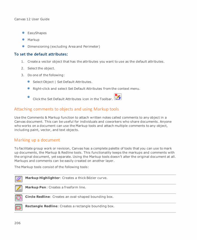
Canvas 12 User Guide
EasyShapes
Markup
Dimensioning (excluding Area and Perimeter)
To set the default attributes:
1. Create a vector object that has the attributes you want to use as the default attributes.
2. Select the object.
3. Do one of the following:
Select Object | Set Default Attributes.
Right-click and select Set Default Attributes from the context menu.
Click the Set Default Attributes icon in the Toolbar.
Attaching comments to objects and using Markup tools
Use the Comments & Markup function to attach written notes called comments to any object in aCanvas document. This can be useful for individuals and coworkers who share documents. Anyonewhoworks on a document can use the Markup tools and attach multiple comments to any object,including paint, vector, and text objects.
Marking up a document
To facilitate group work or revision, Canvas has a complete palette of tools that you can use tomarkup documents, the Markup & Redline tools. This functionality keeps the markups and comments withthe original document, yet separate. Using the Markup tools doesn’t alter the original document at all.Markups and comments can be easily created on another layer.
The Markup tools consist of the following tools:
Markup Highlighter: Creates a thick Bézier curve.
Markup Pen: Creates a freeform line.
Circle Redline: Creates an oval-shaped bounding box.
Rectangle Redline: Creates a rectangle bounding box.
206
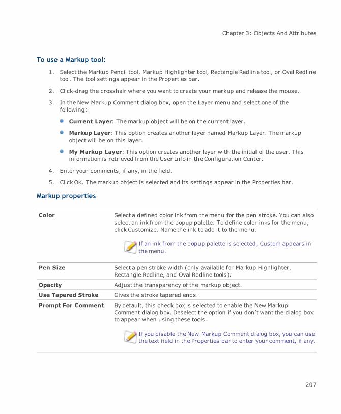
Chapter 3: Objects And Attributes
To use a Markup tool:
1. Select the Markup Pencil tool, Markup Highlighter tool, Rectangle Redline tool, or Oval Redlinetool. The tool settings appear in the Properties bar.
2. Click-drag the crosshair where you want to create your markup and release the mouse.
3. In the New Markup Comment dialog box, open the Layer menu and select one of thefollowing:
Current Layer: Themarkup object will be on the current layer.
Markup Layer: This option creates another layer named Markup Layer. Themarkupobject will be on this layer.
My Markup Layer: This option creates another layer with the initial of the user. Thisinformation is retrieved from the User Info in the Configuration Center.
4. Enter your comments, if any, in the field.
5. Click OK. Themarkup object is selected and its settings appear in the Properties bar.
Markup properties
Color Select a defined color ink from themenu for the pen stroke. You can alsoselect an ink from the popup palette. To define color inks for themenu,click Customize. Name the ink to add it to the menu.
If an ink from the popup palette is selected, Custom appears inthemenu.
Pen Size Select a pen stroke width (only available for Markup Highlighter,Rectangle Redline, and Oval Redline tools).
Opacity Adjust the transparency of the markup object.
Use Tapered Stroke Gives the stroke tapered ends.
Prompt For Comment By default, this check box is selected to enable the New MarkupComment dialog box. Deselect the option if you don’t want the dialog boxto appear when using these tools.
If you disable the New Markup Comment dialog box, you can usethe text field in the Properties bar to enter your comment, if any.
207

Canvas 12 User Guide
If you deselect Always Display This Dialog, the New Markup Comment dialog box doesn’tappear when you create a markup. To enable this dialog box again, select the Prompt ForComment option in the Properties bar when a markup object is selected or created. Click theDisplay Palette button to open the Comments & Markup palette.
To attach comments to objects:
1. Select an object.
2. ChooseObject | Options | Comments & Markup.
3. In the Comments & Markup palette, click the New button.
4. In the New Comment dialog box, type the comment text, then click OK.
The comment appears in the Comments & Markup palette.
A comment can contain up to 64 KB of text (about 65,500 characters). The text appears in a fixedsize and typeface.
When you create comments, you can select, copy, cut, and paste text using the standard keyboardshortcuts. Spell checking, text formatting, and text colors cannot be applied to comments.
Viewing and editing comments
When you open a document, you can view all comments attached to objects and markup objects.
Be sure that Show information tool tips is selected in the Functionality Options page in theConfiguration Center.
You can edit comments that you create, but not those made by others.
When you select an object that has one or more comments attached to it, the object displays yellowselection handles. You can view comments by pointing to objects. When the pointer is on an object,the object’s comments appear in a pop-up window.
Object with comments
208
Chapter 3: Objects And Attributes
To view, edit, and delete comments:
1. ChooseObject | Options | Comments & Markup.
If you select a markup object, click the Display Palette button in the Properties bar toopen the Comments & Markup palette.
2. From the Author drop-down list, select one of the following:
An author’s name: Displays only that author’s comments in the list. The scrolling listdisplays the first lines and the author’s initials for each comment. The initials precedingcomments are retrieved from the User Info in the Configuration Center.
All Authors: Displays comments by all authors.
3. Click a comment to select it.
When you select a comment, Canvas selects the commented object or markup object in thedocument. Yellow selection handles appear around the object to indicate that the object hasone or more comments.
4. Do one of the following:
View: To view a selected comment, click View. The comment text appears in the ViewComments dialog box. Select text and copy it to the Clipboard using standard keyboardshortcuts. You can edit your own comments in the View Comments dialog box, but youcan’t edit or remove others’ comments.
When you view a comment that you can’t edit, the dialog box appears grayed out.
If you changed a comment, click OK to save the changes or click Cancel to discard themand close the dialog box.
If you select a markup object with an attached comment, you can view thecomments in the Properties bar. You can edit your own comments in theProperties bar.
Remove: Select a comment you created. Click Remove to delete the comment from theobject and the Comments palette.
Comments remain attached to objects until you remove them. However, comments are notpreserved by operations that convert objects to different forms. These operations includeKnife, Combine, Extrude, Fractalize, Join, Make Composite, Convert to Paths, and InsertPicture.
209

Canvas 12 User Guide
Generate Text Objects: Click this button to create text objects of any comments thatare attached to objects or markup objects. In the Comment Attributes dialog box, selectthe options you want to use.
Comment attributes
Font Name: Select a font family.
Size: Enter a value or use the scroll box.
Color: Select a color ink for the text object.
Adjust the attributes using the Bold, Italic, and Underlined options.
Properties Layer: Open the menu and select an option. Current Layer places thetext object on the current layer. Markup Layer places the text object onanother layer named Markup Layer. My Markup Layer places the textobject on another layer with the initial of the user. This information isretrieved from the User Info in the Configuration Center.
Author Name: Select this check box if you want the author’s name toappear beside the comment.
Max Line Length: Enter a value or use the scroll box. The default is 2inches.
Position: The position is in relation to the commented object’sbounding box. Select an anchor point.
Assigning and modifying custom object properties
Canvas contains the ability to attach specific user-definable data to any object. This information isstored with the objects and can be viewed or edited from within Canvas.
Assigning custom object properties
The Object Properties function allows you to assign specific information to each component of acomplex object. The properties of an object can include information that will allow you to efficientlytrack cost, inventory, location, and availability. As a result, those who design and manufacture itemssuch as fuel pumps, jet engines or other sophisticated components can better manage productionworkflow.
210
Chapter 3: Objects And Attributes
If you are working with GIS vector files, such as Shapefiles or Tigerfiles, the attributeinformation is available in the Object Properties palette. Click on an object and itsinformation appears.
Attaching information to an object does not affect the size or appearance of the item. All data remainsattached to the object and may be edited at any time within Canvas. Therefore, if the object is sharedor used in another project, then the properties of that object are carried over into the new project.
To open the Object Properties palette:
Select a Canvas object and choose Object | Object Properties.
If the selected item does not have any properties assigned to it, then you will need to create someproperties.
If the object is grouped, then you will need to ungroup it. This allows you to select thevarious individual items to which you wish to assign a property.
To assign properties to an object:
1. From the Object Properties palette menu, select Define Property.
2. In the Define Properties dialog box, click the New button.
3. Select the options for the property.
4. When you have finished defining properties, click OK to close the dialog box.
Once created, the labels are listed in the Properties panel. At any time, you can access and edit yourentries by clicking on any of the properties that are listed in the Properties panel.
211

Canvas 12 User Guide
Define Properties options
Label In this field, you may enter the name of the property; e.g., Size, Weight,Location, Part Number, Tracking Code.
You can also attach multiple labels to each object. Doing so allows you toidentify the object by using one of the assigned labels.
Next, select an option in the Typemenu. This allows you to choose thesearch value for the object.
Type The Type field has the following options: String, Number, Fixed List,Variable List, Boolean, Currency, or Date.
String: You can place just about anything that you want in this field. If aFormat field is used, then it is possible to impose limits on what isentered, use only numbers, or specify n-number of characters. Thefollowing format modifiers are available for String:
“#”: Indicates number“X”: Indicates character“?”: Indicates that you can assign any character
[any other character]: Indicates that this character will appearin the value string at that exact position and exactly as it is enteredin the format.
An example would be assigning the value of:“XXXXXXXXXX” to the handle of the object “Water Valve.” Thisvaluewould not apply to “Gas Valve.”
Using the symbols “####.##” means that “1234.12” is a validentry; however, “1234.123” would not be a valid value for theobject. It will return incorrect results during a search for an item.If a format is not entered, then any string will be accepted.
Number: This option allows you to enter a numerical value for an object.To do so, you must use one of the following formats:
Whole (e.g., 1)Wholewith units (e.g., 1 kg)Decimal (e.g., 1.5)Decimal with Units (e.g., 5.1 kg)Fraction (e.g., 1/2)Fraction with Units (e.g., 1/2 kg)
212
Chapter 3: Objects And Attributes
Fixed List: You can think of this as assigning a key word that can beused to search for items. Be certain to separate each word with asemicolon (;); e.g., “earth;wind;fire”. After setting this property type,you should define a set of items that appear on the list of available valuesfor the property. Enter the desired values in the Format field; e.g., youmay enter values such as “Earth;Wind;Fire” in the Format field. Theseentries will then appear on the list in the Object Properties palette.
Variable List: This option is the same as a fixed list except that you canenter new values at the time of assignment to the object. After youdefine a set of values, you may want to add a new value to the set thatappears in the Object Properties menu. Tomake these changes, youneed only to enter a value in the Object Properties palette.
Boolean: This is used when the valuewill be Yes or No. You may changethe value to True or False, Positive or Negative, 0 or 1, etc.
Currency: There are two format types for the currency property. Theyare Monetary Sign Leads (e.g., USD 100.00) and Monetary Sign Follows(e.g., 100.00 USD).
The default setting for the currency property is Monetary Sign Leads.This property is set in the same manner as the previously describednumbers with units. You need only to enter a value and a monetary signin the Value field to have a default monetary sign set. The sign that youenter will then become the default setting. It will be automatically addedeach time that you change a value.
If you enter a value and a monetary sign that differs from the default,then the change will be rejected. If the default sign was not defined,then you have to enter a number and a monetary sign each time that youchange the value of the property. An advantage of not having a defaultmonetary sign is that you are not constrained to the use of the defaultsetting when entering a different sign.
A monetary sign must always be present in the valuewhenworking with currencies. If there is not a default setting, youmust enter a number and themonetary sign.
Date: The Date property can be set in any of six different formats. Theyare grouped into twomajor format types:
Full Date formats: This setting forces you to set a date whichconsists of a two-digit day, two-digit month, and four-digit year;
213
Canvas 12 User Guide
e.g, for February, you must enter “02” instead of “2”. Therefore,February 7th, 2001 could be entered as 02/07/2001.
Short Date formats: Using this setting the date will consist ofeither a one-digit or two-digit day and a one-digit or two-digitmonth. A two-digit year will always be required. This means thatzero (‘0’) will not be used as the first number for month or day;e.g., February should be represented as “2” (not as “02”);however, zerowill be accepted as the first number of a year.This means that you may enter 2001 as “01”. Therefore,February 7th, 2001 could be entered as 2/7/01.
Each of the previously discussed sets have three separateformats:
month/day/year: Represented in the palette as “03/29/1999”and “3/29/99” respectively
day/month/year: Represented in the palette as “29/03/1999”and “29/3/99” respectively
year/month/day: Represented in the palette as “1999/03/29”and “99/3/29” respectively
Once you choose a Type from the above options, you must establish thecorrect Format. The Format section provides details for each of the Typechoices and its associated Format options.
214

Chapter 3: Objects And Attributes
Format Assigning a format depends on which of the previously mentioned typeswere selected.
Value Allows you to enter a default value for an object.
Prompt A message or other data that is entered here will be displayed wheneveryou place the pointer over the property name in the Object Propertiespalette.
To use this feature, select the Show Information Tooltips checkbox in the Functionality options in the Configuration Center.
To define a unit:
1. In the Define Properties dialog box, set the Type as “Number”.
2. Set the Format to be one of those with units.
3. Enter a number followed by unit as the Value; e.g., “100 kg”. The unit will become thedefault for that property.
This means that if you were to enter the setting of “100 cm”, then “cm” will become your defaultsetting. Therefore, when you enter a new value for the property in the Object Properties palette,you will only have to enter the number for that property. The unit will automatically be appendedto reflect the unit “cm.” If you enter both a number and a unit and the unit differs from thedefault, then the entry will be rejected.
If you do not specify a default unit for the property, then you will need to enter anumber and a unit each time that you change the value. The advantage of not having adefault unit is that you can enter a different unit without being constrained by thedefault setting.
4. Once you have completed entering all of the properties to the object, click OK. When theObject Properties palette is active, all assigned properties will appear in the palette wheneveryou select the object.
Adding, modifying, and deleting properties
You can modify, delete, or add new properties. Although it is possible to add a property to two ormore selected objects, you can only delete or define properties while one object is selected.
215
Canvas 12 User Guide
To add a property to an object or objects:
1. Open the Object Properties palette menu and select Add Property.
If you have Canvas GIS+, the palette menu contains additional options: Select byProperty, Table View, Statistics, and Calculate Value.
2. In the Add Property dialog box, enter a name in the Name field. In the Object Properties TableView palette, a new column is created with this Name.
3. Select either Text or Numeric from the Typemenu.
4. Enter the appropriate value in the Value field.
The Compute values and Expression feature are for users that have Canvas GIS+.
5. Select the Compute values check box if you want to create an expression.
6. Click the Expression button to open the Expression Builder dialog box. If you select Numeric,the result of the expression must be numeric as well.
To delete a property:
1. Open the Object Properties palette.
2. Select the property in the palette.
3. Open the palette menu and choose Delete Property.
To create common properties for objects:
When two or more objects are selected, the list of properties that are common for all of those objectsis shown. Working with common properties is similar to working with a list of properties from oneobject.
1. Select two or more objects to which you want to assign common properties.
2. Open the palette menu and select Add Property to open the Add Property dialog box (see "Toadd a property to an object or objects:" on page 216).
To modify object properties:
1. Select an object that has already defined properties.
2. Open the Object Properties palette menu.
216
Chapter 3: Objects And Attributes
3. Select Define Property to open the Define Property dialog box (see "Assigning custom objectproperties" on page 210).
To find all objects that share an identical property:
1. Select the property item in the Object Properties palette that objects share.
2. Click the Find button and all objects that contain that property item are selected.
To copy property items to another object:
1. Select the object whose properties you want to copy.
2. Click the Copy button.
3. Select the other object and click the Paste button. The objects now share identicalproperties.
Viewing object properties
If you want to view an object's properties, you can use the Object Properties Table View palette to seeall the properties in a table. This palette lets you view custom properties that you have assigned to anobject as well as geometric properties such as the width and height of the object, locationinformation, pen weight and color, and fill color.
To view object properties in a table:
1. ChooseObject | Object Properties Table View.
2. Click one of the following:
All: Displays both custom and geometric properties.
Object Properties: Displays any custom properties you have added to the object.
Geometric Properties: Displays the geometric properties of an object.
3. Do one of the following:
To show all the properties, click Show All.
To show just selected properties, select the properties you want to display, and clickShow Selected.
217
Canvas 12 User Guide
To select properties to view:
1. ChooseCustomize from the Object Properties Table View palette menu.
2. In the Select Properties To Display dialog box, select the check boxes for the properties youwant to display.
3. Click the Move First, Move Up, Move Down, and Move Last buttons to change the order of theproperties displayed.
4. Click OK.
Saving properties
Once you have displayed the properties for an object, you can choose to save that data to a text file.
To save the displayed properties:
1. ChooseSave from the Object Properties Table View palette menu.
2. In the Save Object Properties dialog box, select the location where you want to save the file,type a file name, and click Save.
Selecting objects by property
The Select by Property command lets you select objects according to property information. Create aquery based on one or more selected properties and property values. For example, if you wanted toselect objects with a width greater than 2, you could create the following query:
"Width" >= 2.0
To select objects by property:
1. ChooseSelect by Property from the Object Properties Table View palette menu.
2. In the Select by Property dialog box, create a query with the properties you want to use forselecting objects.
3. Click OK.
To save a query:
1. In the Select by Property dialog box, create a query.
2. ChooseSave Query/Expression in the Select by Property palette menu.
218
Chapter 3: Objects And Attributes
3. In the Save query/expression dialog box, select the location where you want to save the file,type a file name, and click Save.
To load a saved query:
1. Choose Load Query/Expression in the Select by Property palette menu.
2. In the Load query/expression dialog box, select the location where you saved the query file,select the file, and click Open.
Select by property options
Method Select either Create new selection, Add to selection, Remove fromselection, or Select from selection depending on the desired outcome.
Query field The query will appear in this field. Use a combination of the Operatorbuttons, Property list, Property Value list, and Function Category list tocreate a query.
Operator buttons These are themost common operators. Click the button and the operatoris added to the Query field.
Property list Double-click a property to add it to the Query field. The Property Valuelist loads the related property values.
Property Value list After double-clicking an item in the Property list, select a value in theProperty Value list. Double-click the value to add it to the Query field.
Function Category This list contains the possible operators. Double-click an operator to addit to the Query field. To filter the operators, select a category of operatorfrom the Function Category drop-down list.
Statistics by property
Use the Statistics by Property command to obtain the total number of objects on the current layer orwithin the current selection. The information is displayed in a histogram as well.
To view statistics by property:
ChooseStatistics by Property from the Object Properties Table View palette menu.
219
Canvas 12 User Guide
Statistics by property dialog box
Scope Select the scope of the view:
Layer: Displays statistics for objects on the current layer.Selection:Displays statistics for objects that are currentlyselected.Table View:
Property Select an object property.
Expression Click this button to open the Expression Builder dialog box to create aquery.
Statistics This section indicates the statistics for the selected property.
Show StdDev Select this check box to show the standard deviation. The standarddeviation appears as a dotted line.
Show Mean Select this check box to show the average value for the selected propertywithin the scope.
Columns Select the number of columns to display in the histogram.
Palette menu You can select one of the following options:
Copy statistics (as text): Copies the statistics as text to theclipboard. You can then paste it into your document.Copy selected statistics value (as text): Copies the selectedvalue as text to the clipboard. You can then paste it into yourdocument.Place histogram (as Canvas objects): Places the histogram inthe upper left corner of the layout area.
Calculating values
You can calculate values for a custom property in the Object Properties Table View palette.
To calculate values:
1. In the Object Properties Table View palette, click a column heading and choose CalculateValues.
220
Chapter 3: Objects And Attributes
2. In the Expression Builder dialog box, create an expression by selecting properties, a functioncategory, and .
3. Click OK.
Expression builder
The Expression Builder dialog box, accessible from the palettes such as the Statistics by Propertypalette and the Calculate Values command from the Object Properties Table View palette, is verysimilar to the Select by Property dialog box. It lets you create expressions, similar to queries.
Expression Builder dialog box
Expression field The query will appear in this field. Use a combination of the Operatorbuttons, Property list, Property Value list, and Function Category list tocreate a query.
Operator buttons These are themost common operators. Click the button and the operatoris added to the Query field.
Property list Double-click a property to add it to the Query field. The Property Valuelist loads the related property values.
Property Value list After double-clicking an item in the Property list, select a value in theProperty Value list. Double-click the value to add it to the Query field.
Function Category This list contains the possible operators. Double-click an operator to addit to the Query field. To filter the operators, select a category of operatorfrom the Function Category drop-down list.
Adding properties
You can add custom text or numerical properties to objects while you are viewing them in the ObjectProperties Table View palette using the Add Property command.
To add properties:
1. ChooseAdd Property from the Object Properties Table View palette menu.
2. In the Add Property Dialog Box, select the Add Property options.
3. Click OK.
221
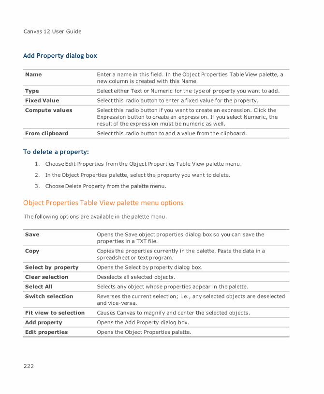
Canvas 12 User Guide
Add Property dialog box
Name Enter a name in this field. In the Object Properties Table View palette, anew column is created with this Name.
Type Select either Text or Numeric for the type of property you want to add.
Fixed Value Select this radio button to enter a fixed value for the property.
Compute values Select this radio button if you want to create an expression. Click theExpression button to create an expression. If you select Numeric, theresult of the expression must be numeric as well.
From clipboard Select this radio button to add a value from the clipboard.
To delete a property:
1. Choose Edit Properties from the Object Properties Table View palette menu.
2. In the Object Properties palette, select the property you want to delete.
3. ChooseDelete Property from the palette menu.
Object Properties Table View palette menu options
The following options are available in the palette menu.
Save Opens the Save object properties dialog box so you can save theproperties in a TXT file.
Copy Copies the properties currently in the palette. Paste the data in aspreadsheet or text program.
Select by property Opens the Select by property dialog box.
Clear selection Deselects all selected objects.
Select All Selects any object whose properties appear in the palette.
Switch selection Reverses the current selection; i.e., any selected objects are deselectedand vice-versa.
Fit view to selection Causes Canvas to magnify and center the selected objects.
Add property Opens the Add Property dialog box.
Edit properties Opens the Object Properties palette.
222
Chapter 3: Objects And Attributes
Statistics by property Opens the Statistics by property dialog box.
Customize Opens the Select Properties to display dialog box in which you can selectthe properties that you want to display.
Inks: colors & patterns
Inks in Canvas are solid colors or multicolored patterns that you apply to vector and text objects. Youcan apply inks to the interiors and outlines of vector objects and text.
This section describes how to create and apply inks, from basic solid color inks to custommulticolored inks. It also explains how to define inks.
Presets palette
Use the Presets palette to apply inks, select the current inks for new objects, load inks, and deleteinks.
To open the Presets palette:
Do one of the following:
Click one of the ink or stroke icons in the Toolbox, then drag the palette away from theToolbox to float it.
ChooseWindow | Palettes | Presets.
223
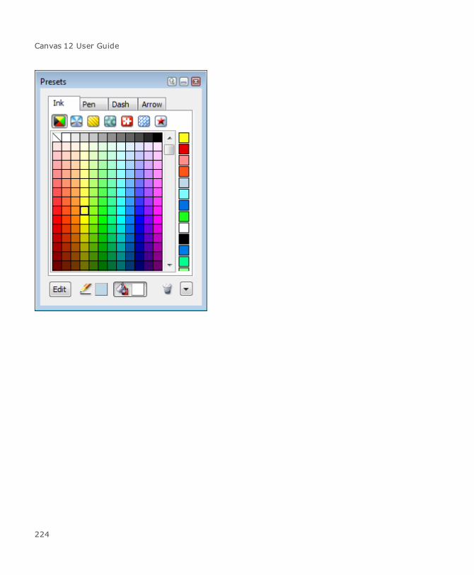
Canvas 12 User Guide
224
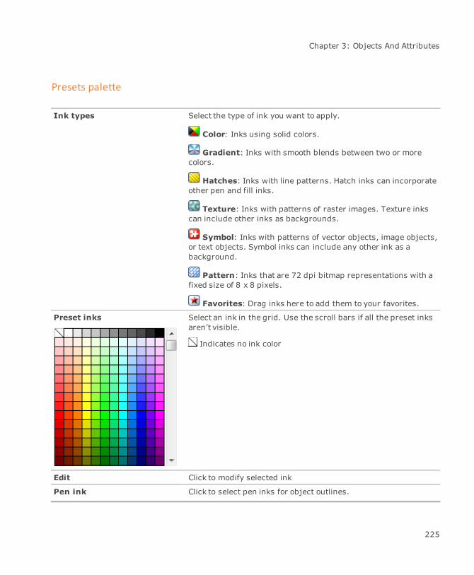
Chapter 3: Objects And Attributes
Presets palette
Ink types Select the type of ink you want to apply.
Color: Inks using solid colors.
Gradient: Inks with smooth blends between two or morecolors.
Hatches: Inks with line patterns. Hatch inks can incorporateother pen and fill inks.
Texture: Inks with patterns of raster images. Texture inkscan include other inks as backgrounds.
Symbol: Inks with patterns of vector objects, image objects,or text objects. Symbol inks can include any other ink as abackground.
Pattern: Inks that are 72 dpi bitmap representations with afixed size of 8 x 8 pixels.
Favorites: Drag inks here to add them to your favorites.
Preset inks Select an ink in the grid. Use the scroll bars if all the preset inksaren’t visible.
Indicates no ink color
Edit Click to modify selected ink
Pen ink Click to select pen inks for object outlines.
225
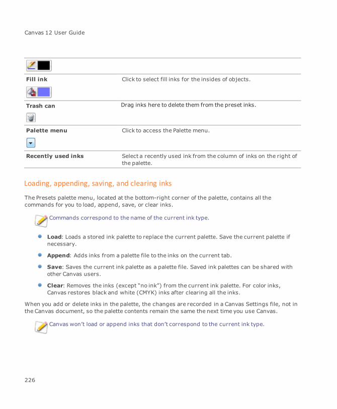
Canvas 12 User Guide
Fill ink Click to select fill inks for the insides of objects.
Trash can Drag inks here to delete them from the preset inks.
Palette menu Click to access the Palette menu.
Recently used inks Select a recently used ink from the column of inks on the right ofthe palette.
Loading, appending, saving, and clearing inks
The Presets palette menu, located at the bottom-right corner of the palette, contains all thecommands for you to load, append, save, or clear inks.
Commands correspond to the name of the current ink type.
Load: Loads a stored ink palette to replace the current palette. Save the current palette ifnecessary.
Append: Adds inks from a palette file to the inks on the current tab.
Save: Saves the current ink palette as a palette file. Saved ink palettes can be shared withother Canvas users.
Clear: Removes the inks (except “no ink”) from the current ink palette. For color inks,Canvas restores black and white (CMYK) inks after clearing all the inks.
When you add or delete inks in the palette, the changes are recorded in a Canvas Settings file, not inthe Canvas document, so the palette contents remain the same the next time you use Canvas.
Canvas won’t load or append inks that don’t correspond to the current ink type.
226

Chapter 3: Objects And Attributes
Identifying inks
You can display color names that identify the inks that are stored in the Presets palette. This functionaffects all ink types in the palette. If an ink was not given a name, no name will appear.
You can also differentiate between RGB, CMYK, and spot colors when working with color inks byshowing color icons.
If the color ink type is selected, the inks will indicate RGB, CMYK, or grayscale percentages. Forgradient, hatch, symbol, pattern, and texture inks, a name is displayed.
To display ink names:
Open the Inks palette menu and choose Display Color Names.
To hide the ink names:
Open the Inks palette menu and deselect Display Color Names.
227

Canvas 12 User Guide
To identify inks with color icons:
Color icons help you identify RGB, CMYK, and spot colors when working with the color inks.
Selecting Show Color Icons only affects the appearance of the color inks in the Presetspalette. The other inks are not affected.
To display color icons:
Select the color ink icon and open the palette menu. ChooseShow Color Icons.
To hide the color icons:
ChooseHide Color Icons in the menu.
RGB color
CMYK color
Spot color
The color inks can contain inks defined with RGB, CMYK, grayscale, and spot colors.
The symbol for RGB color inks has tiny red and blue triangles and a green square. Thesymbol appears at the upper-left of RGB color cells.
The symbol for spot color inks is a white triangle. The symbol appears at the lower-right ofspot color cells. If the Show Color Names option is activated, no symbol appears for the spotcolor.
No symbol appears on CMYK or Grayscale ink cells.
When working with color inks, if the Ink tab contains only CMYK colors, no symbols appearwhen you choose Show Color Icons.
Arranging ink cells
To rearrange ink cells in the Presets palette:
Drag a cell within the palette and drop it where you want to place it.
228

Chapter 3: Objects And Attributes
To move contiguous ink cells to a new location:
Click the first ink cell and then Shift+click another cell. Canvas highlights all cells between thecolors you click.
To select non-contiguous cells:
Ctrl+click the cells you want to select. Drag the selected cells to a new location in the palette.
Applying preset inks
To apply inks to existing objects:
Select the objects and then choose pen and fill inks.
To change the inks that Canvas applies to new vector and text objects:
Deselect all objects, then choose pen and fill inks. The ink icons in the toolbox show the currentinks.
To remove an ink from the palette:
Drag the ink cell to the trash can.
Since pen inks are applied to the strokes of objects, the appearance of an object’s pen ink is affectedby the shape of the object’s stroke (see "How inks affect strokes" on page 258).
Attributes palette
Use the Attributes palette and its various ink managers to create your own inks. Each ink type has itsown manager. Flip open themanagers to create inks, adjust inks in objects, and change the Presetspalette’s inks.
To open the Attributes palette:
Do one of the following:
In the Presets palette, click the Edit button.
ChooseWindow | Palettes | Attributes.
Ink managers
Six icons are located at the top of the Inks managers, which you click to access the available ink typesand their respective managers: color, gradient, hatch, texture, symbol, and pattern. The circular
229

Canvas 12 User Guide
icon with a diagonal line represents “no ink”.
Each ink type has its own manager so you create custom inks and add them to the Presetspalette.
If you select color as the ink type, you can access the RGB, CMYK, HSL, and Pantone colorsystems.
Using the Ink managers
Every ink manager shows a preview of the current ink. The preview changes as you modify the ink. Ifan object is selected, the ink is applied immediately. You can also drag the ink from the preview boxto deselected objects.
230

Chapter 3: Objects And Attributes
To edit an object’s ink:
Click the pen ink icon or fill ink icon. Then select an object; its ink becomes the current ink in themanager. Modify the ink.
To make a new ink:
Use the appropriatemanager to customize the current ink.
Type a name in the text box to name it.
To add an ink to the Presets palette:
Click the Add Preset button.
To make an ink the current ink:
Deselect any objects and click the pen ink icon or fill ink icon. Then select an ink in any of themanagers.
To apply an ink to a deselected object:
Drag from the preview box to the inside or outline of the object.
Creating color inks
The Color Manager gives you the ability to maintain and manage color inks by providing access toRGB, CMYK, HSL, and Pantone models. A Color Spectrum Strip is also available for quick color pickupof any color supported by Canvas.
Color manager controls
The Color Manager’s controls depend on the selected color system and model. Some controls arecommon among the different color models.
Current ink Shows the current ink.
Last-applied ink Shows the last applied ink.
Bars Use the sliders, or enter values in the text boxes, to specify color values.RGB values go from 0 to 255. CMYK values go from 0--- to 100%. HSLvalues go from 0 to 360° (hue) and 0 to 100% (saturation andlightness).
Spot Color Select to set up a spot color. Type a color name in the text box. Spotcolors print on separate plates when you make color separations.
231

Canvas 12 User Guide
Tint Color Select the color to apply to the current color.
Tint value Enter the percentage of tint to be applied.
Swatchbook Shows colors made from 0-100%mixtures of two CMYK colors. To selecta color, click in the swatchbook; the color values appear in the textboxes.
Select the two colors for the swatchbook. To add a third or fourth color,enter percentages in the C M Y K text boxes.
Color wheel Click in the wheel or drag the selector to pick a color, or enter values inthe HSL text boxes.
Lightness Drag the slider or enter a number in the L text box to set the lightnessfor the entire color wheel.
Gamut warning When the current color can’t be printed with CMYK inks, a warningsymbol and color box appear. Click the color box to replace the currentcolor with the closest color that is within the CMYK gamut.
Gamut warnings appear only in RGB and HSL systems.
PANTONE You can use commercial reference system colors for process and spotcolors. Choose PANTONE in the pop-up menu in the Color manager (see"PANTONE" on page 234).
The PANTONE System includes hundreds of spot colors designed to beprinted with special inks. You should select the correct color group forthe paper stock on which the colors will be printed; e.g., the PANTONECVC colors are calibrated for printing on coated paper stock. ThePANTONE Pro-Sim colors are not spot colors. These colors are designedto be printed with standard process inks.
Color systems
Use the drop-down menus to access to the various color controls. This will allow you to select a colormatching system and select colors that are needed for commercial printing.
To access the color system controls:
In the Attributes palette, click on a color system icon.
CMYK
RGB/Grayscale
232

Chapter 3: Objects And Attributes
HSL
PANTONE
To define colors in Canvas:
Use CMYK, RGB, and Grayscale color systems.
Colors displayed on a monitor can only approximate the appearance of printed colors. Be sure todiscuss color reproduction with your commercial printer and obtain accurate proofs for colorprojects.
CMYK
The CMYK color system is used in four-color process printing. Define colors as mixtures of Cyan (C),Magenta (M), Yellow (Y), and Black (K) printing inks; e.g., to create green, mix cyan and yellow.
The CMYK system is appropriate for illustrations that will be separated for commercial printing.
RGB
The RGB color system is used in computer monitors. Define colors as mixtures of Red (R), Green (G),and Blue (B) light; e.g., to create purple, mix red and blue.
The RGB system is appropriate for graphics displayed on a monitor, such as presentations and Webpages.
Avoid RGB colors in documents intended for commercial printing. Canvas will convert RGBcolors to CMYK colors if you output color separations.
Grayscale
The Grayscale model lets you define shades of gray. Grayscale colors are neutral when used with RGBor CMYK colors. In RGB Color images, grayscale colors are equal amounts of red, green, and blue. Inimage channels, Grayscale colors are pure gray. In vector objects, text, or CMYK Color images,Grayscale colors are percentages of black. In color separations, Grayscale colors appear aspercentages of black.
HSL
The HSL models let you define RGB colors using Hue (H), Saturation (S), and Lightness (L) values.This way of defining colors is familiar to artists. HSL models let you adjust saturation and lightness,without changing a basic hue, such as red or green.
233
Canvas 12 User Guide
PANTONE
When you choose a PANTONE reference system color set, you can search for and select colors byname.
Color name The selected color’s name. Names of reference colors can’t be changed.
Color system Choose the reference system you want to use in the pop-up menu.
Color list Click a color in the list to select it. Use the scroll bar to scroll the list.
Current color preview Shows the current color.
Page The page number of colors shown in the color list. Type a number to goto the page.
Find Click to select a color by name. In the Find dialog box, type the colorname or number and click OK. Canvas selects the color (if found) in thecolor list.
Tint Value Not available for process colors. Enter a screen percentage to apply tothe selected color. Use 100% for solid color and lower values for screensof the solid color.
Spot Color option Available with the Pro-Sim and Process systems, this option lets youspecify colors to use as spot colors in separations.
Specifying tints
Specify a tint color and amount in the CMYK or RGB system. Tinting with white screens the originalcolor. The screen percentage is 100 minus the tint value; e.g., 80% white tint results in 20% of theoriginal color.
For other tint colors, Canvas multiplies the tint values by the difference between the original and tintcolor values, and then adds the result to the original color values.
After creating a new ink, make sure you click the Add Preset button on the Attributespalette.
To create new color inks:
1. Choose a color systemand model from the drop-down menu (see "Color systems" on page232).
2. Use the Color manager controls to change the ink’s color values.
234

Chapter 3: Objects And Attributes
3. Click the left preview box to restore the original ink.
To name the ink: Type the name in the text box.
To define it as a spot color: Select the Spot Color box.
To apply the ink to non-selected objects: Drag it from the preview box to theobjects.
To add the ink to the Presets palette: Click the Add Preset button on the Attributespalette. The new ink is added to the appropriate ink type; i.e., if you create a Pattern ink,the new ink is added to the Pattern type.
Creating blends of color inks
Select two color cells and create a blend of colors to add to the color inks tab of the Presets palette.
To blend colors:
1. Select the Ink tab of the Presets palette.
2. Select color as the Ink type.
3. Click the ink cell that is to start the blend, then Ctrl-click the cell to end the blend.
4. Open the palette menu and choose Blend.
5. In the dialog box, enter the number of steps you want in the blend and then click OK. Canvascreates the blend and adds the new cells to the color inks at the end.
The color editor
In Canvas, dialog boxes and palettes that let you choose colors have a color icon that opens a pop-upcolor palette. On the color palette there is a color editor icon so you can access the Color Editor dialogbox to create a custom color.
To open the color editor:
1. Click the color icon to see the color palette.
2. Click the color editor icon to open the Color Editor dialog box.
The color icon appears in the following dialog boxes and palettes:
Attributes (Ink) Color manager (CMYK Tints & RGB Tints only)
235
Canvas 12 User Guide
Gradient manager
Hatch manager (pen color pop-up only)
Attributes (Pen) Neon manager
Parallel manager
Layers Layer Options dialog box
Color calibration GamutWarning dialog box
Image editing Duotone Options dialog box
New Channel dialog box
Channel Options dialog box
Create Image dialog box
Effects Extrude palette
Click the color icon to open a palette that has the color inks that are currently available in the Presetspalette. Click the Custom icon to open the Color Editor dialog box.
236

Chapter 3: Objects And Attributes
Color Editor dialog box
To create a custom color with the Color Editor dialog box:
1. Open the Color Editor dialog box. This dialog box is almost identical to the Color manager.
If you plan to export a document to another application in EPS format and make spotcolor separations, be sure the spot color names match exactly in both applications. Anyvariation will cause problems.
2. To use a different color model, click on the color model button and choose an option in themenu. Depending on the chosen option, the Color Editor shows a different set of controls(see "Color manager controls" on page 231).
3. Use the color controls to create a custom color.
4. To specify that you want the color you define to be a spot color, make sure you enter a namein the text box. Then select Spot Color.
5. When you have the color you want, click OK. The color appears in the color icon.
237
Canvas 12 User Guide
Working with gradient inks
A gradient is a gradual blending of colors. A gradient ink can blend two or more colors in a variety ofstyles. Like other inks, gradient inks can be applied as fill inks or pen inks to vector and text objects.
The appearance of a gradient ink depends on several factors. Gradients appear smooth on monitorsthat display millions of colors, but can appear coarse and dithered on monitors that display only 256colors. Themore extreme the difference in colors, the coarser a gradient can appear. When agradient has large color transitions, it appears smoother in an object that is large enough to show allthe transitions.
Applying gradient inks
Canvas gives you the option of applying gradients directly from the Presets palette or using theVector Gradient tool. When a gradient ink is applied via the Presets palette, the gradient effect iscentered within the object. If you want non-centered effects, use the Vector Gradient tool.
To apply gradient inks from the Presets palette:
Select the Pen or Fill ink icon on the Presets palette.
If object is selected, click on the gradient ink cell.
If object is not selected, click on the gradient ink cell and drag the ink to the object.
See "Applying preset inks" on page 229, for complete steps about applying inks.
238
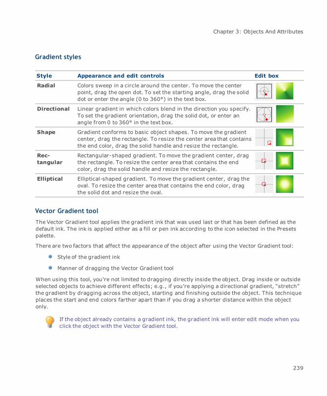
Chapter 3: Objects And Attributes
Gradient styles
Style Appearance and edit controls Edit box
Radial Colors sweep in a circle around the center. Tomove the centerpoint, drag the open dot. To set the starting angle, drag the soliddot or enter the angle (0 to 360°) in the text box.
Directional Linear gradient in which colors blend in the direction you specify.To set the gradient orientation, drag the solid dot, or enter anangle from 0 to 360° in the text box.
Shape Gradient conforms to basic object shapes. Tomove the gradientcenter, drag the rectangle. To resize the center area that containsthe end color, drag the solid handle and resize the rectangle.
Rec-tangular
Rectangular-shaped gradient. Tomove the gradient center, dragthe rectangle. To resize the center area that contains the endcolor, drag the solid handle and resize the rectangle.
Elliptical Elliptical-shaped gradient. Tomove the gradient center, drag theoval. To resize the center area that contains the end color, dragthe solid dot and resize the oval.
Vector Gradient tool
The Vector Gradient tool applies the gradient ink that was used last or that has been defined as thedefault ink. The ink is applied either as a fill or pen ink according to the icon selected in the Presetspalette.
There are two factors that affect the appearance of the object after using the Vector Gradient tool:
Style of the gradient ink
Manner of dragging the Vector Gradient tool
When using this tool, you’re not limited to dragging directly inside the object. Drag inside or outsideselected objects to achieve different effects; e.g., if you’re applying a directional gradient, “stretch”the gradient by dragging across the object, starting and finishing outside the object. This techniqueplaces the start and end colors farther apart than if you drag a shorter distance within the objectonly.
If the object already contains a gradient ink, the gradient ink will enter edit mode when youclick the object with the Vector Gradient tool.
239
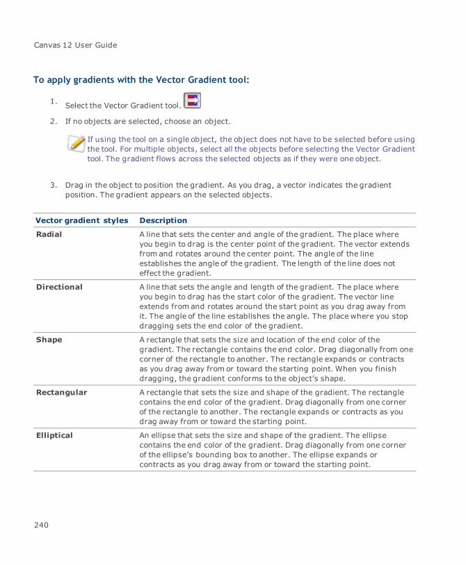
Canvas 12 User Guide
To apply gradients with the Vector Gradient tool:
1. Select the Vector Gradient tool.
2. If no objects are selected, choose an object.
If using the tool on a single object, the object does not have to be selected before usingthe tool. For multiple objects, select all the objects before selecting the Vector Gradienttool. The gradient flows across the selected objects as if they were one object.
3. Drag in the object to position the gradient. As you drag, a vector indicates the gradientposition. The gradient appears on the selected objects.
Vector gradient styles Description
Radial A line that sets the center and angle of the gradient. The place whereyou begin to drag is the center point of the gradient. The vector extendsfrom and rotates around the center point. The angle of the lineestablishes the angle of the gradient. The length of the line does noteffect the gradient.
Directional A line that sets the angle and length of the gradient. The place whereyou begin to drag has the start color of the gradient. The vector lineextends from and rotates around the start point as you drag away fromit. The angle of the line establishes the angle. The placewhere you stopdragging sets the end color of the gradient.
Shape A rectangle that sets the size and location of the end color of thegradient. The rectangle contains the end color. Drag diagonally from onecorner of the rectangle to another. The rectangle expands or contractsas you drag away from or toward the starting point. When you finishdragging, the gradient conforms to the object’s shape.
Rectangular A rectangle that sets the size and shape of the gradient. The rectanglecontains the end color of the gradient. Drag diagonally from one cornerof the rectangle to another. The rectangle expands or contracts as youdrag away from or toward the starting point.
Elliptical An ellipse that sets the size and shape of the gradient. The ellipsecontains the end color of the gradient. Drag diagonally from one cornerof the ellipse’s bounding box to another. The ellipse expands orcontracts as you drag away from or toward the starting point.
240
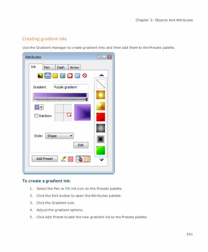
Chapter 3: Objects And Attributes
Creating gradient inks
Use the Gradient manager to create gradient inks and then add them to the Presets palette.
To create a gradient ink:
1. Select the Pen or Fill ink icon on the Presets palette.
2. Click the Edit button to open the Attributes palette.
3. Click the Gradient icon.
4. Adjust the gradient options.
5. Click Add Preset to add the new gradient ink to the Presets palette.
241
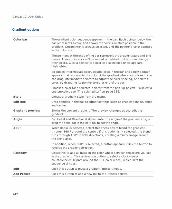
Canvas 12 User Guide
Gradient options
Color bar The gradient color sequence appears in the bar. Each pointer below thebar represents a color and shows the color’s relative position in thegradient. One pointer is always selected, and the pointer’s color appearsin the color icon.
The pointers at the ends of the bar represent the gradient start and endcolors. These pointers can’t be moved or deleted, but you can changetheir colors. Click a pointer to select it; a selected pointer appearshighlighted.
To add an intermediate color, double-click in the bar and a new pointerappears that represents the color of the gradient where you clicked. Youcan drag intermediate pointers to adjust the color spacing, or delete acolor, by dragging its pointer to either end of the bar.
Choose a color for a selected pointer from the pop-up palette. To select acustomcolor, see "The color editor" on page 235.
Style Choose a gradient style from the menu.
Edit box Drag handles in the box to adjust settings such as gradient shape, angleand center.
Gradient preview Shows the current gradient. The preview changes as you edit thegradient.
Angle For Radial and Directional styles, enter the angle of the gradient axis, ordrag the solid dot in the edit box to set the angle.
360º When Radial is selected, select this check box to blend the gradientthrough 360 ° around the center. If this option isn’t selected, the blendruns through 180° in both directions, creating a mirror image aroundthe blend axis.
In addition, when 360° is selected, a button appears. Click the button toreverse the gradient direction.
Rainbow Select this to add all hues on the color wheel between the colors you setin the gradient. Click a direction button to select a clockwise orcounterclockwise path around the HSL color wheel, which sets thesequence of hues.
Edit Click this button to place a gradient into edit mode.
Add Preset Click this button to add a new ink to the Presets palette.
242
Chapter 3: Objects And Attributes
Modifying gradients
There are various ways of modifying gradient inks.
To edit a gradient ink with the Gradient manager:
1. Open the Gradient manager in the Attributes palette.
2. Select the object. The Gradient manager indicates the ink settings when the object isselected.
3. Click the Edit button in the Gradient manager to put the gradient ink into edit mode. You cannow change the direction or position of the gradient. Modifications appear in the objectautomatically.
To edit a gradient ink via a context menu:
1. Select an object that contains either a gradient fill or pen ink.
2. Right-click to open the menu.
3. Select either Edit Frame Gradient or Edit Fill Gradient depending the use of the gradient ink.The gradient ink should enter edit mode.
4. Make the desired changes in position and direction.
5. Right-click on the individual color nodes to open a color palette. The Gradient manager is alsoavailable for color changes (see "To create a gradient ink:" on page 241).
6. Press Esc to exit edit mode.
To edit a gradient ink with the Vector Gradient tool:
1. Select an object that contains either a gradient fill or pen ink.
2. Click on the Vector Gradient tool. The gradient ink is in edit mode.
3. Make the desired changes in position and direction.
4. Right-click on the individual color nodes to open a color palette. You can click on the Custombutton to open the Color Editor (see "Color Editor dialog box" on page 237). The Gradientmanager is also available for color changes (see "To create a gradient ink:" on page 241).
5. Press Esc to exit edit mode.
243

Canvas 12 User Guide
Working with hatch inks
Hatch inks are patterns made of groups of lines. These inks are often used in illustrations todistinguish different materials in cross sections, machine diagrams, and maps.
Specify the number of line groups as well as the angle, offset, and origin of each group. Assign a pensize, color, and dash to each line group, and select a fill ink for the background of the hatch ink.
Hatch inks
Click on the Hatch icon to open the hatch inks in the Presets palette. Use this palette to apply presethatch inks to objects or store customized hatch inks that you create in the Hatch manager (see"Hatch manager" on page 244).
If you create a new ink in the Hatch manager, click the Add Preset button to add it to thePresets palette.
To apply hatch inks:
Make sure you select either the Pen or Fill ink icon on the Presets palette.
If object is selected, click on the hatch ink cell.
If object is not selected, click on the hatch ink cell and drag the ink to the object.
See "Applying preset inks" on page 229, for complete steps about applying inks.
Creating hatch inks
Use the Hatch manager in the Attributes palette to create hatch inks and then add them to the Presetspalette.
Hatch manager
When you create a hatch ink, set the number of line groups and other attributes.
Preview Click a line group in the preview box to select it. Tiny handles appearwhere the selected group meets the edge.
Pen color Choose a color for the selected line group in the palette. Choose a presetcolor or define a custom color; see "The color editor" on page 235.
Fill ink Select an ink to use as the hatch ink background.
244
Chapter 3: Objects And Attributes
Dash Choose a dash pattern for the selected line group.
Layer If the hatch ink has different layers, choose the layer from this menu.
New Click this button to add a new layer. When a new layer is active, you canadd another line group.
Clear Click this button to delete the current layer.
See "To add or modify a line group:" on page 245 for information on setting Pen, Angle, Offset, andOrigin.
Modifying hatch inks
When you want to change an existing hatch ink, select the hatch ink and click the Edit button to openthe Hatch manager in the Attributes palette.
To change the background color:
1. Click on the fill icon to open the pop-up Presets palette. This palette is identical to the Presetspalette. Use any ink type that is currently available on the palette.
2. Select the new background ink.
3. Click the Add Preset button to add the modified ink to the hatch inks in the Presets palette.
To add or modify a line group:
If you want to create a hatch ink that has crossing lines, the hatch ink will have to containdifferent layers. If the hatch ink contains only one line group, then one layers is sufficient.
To add a new line group: Click the New button in the Hatch manager and then definethe line.
To adjust a line group: Select a layer from the Layer menu in the Hatch manager (ifthe hatch ink contains more than one line group), and then make any modifications in theHatch manager. You can even add more line groups by adding layers.
A line group is selected when selection handles appear where the line group touches the Previewwindow. Once selected, the following line group attributes can bemodified:
Attribute Description
Line group color Click on the pen icon to open the pop-up color palette. Choose a presetcolor or define a custom color in the Color Editor dialog box (see "Color
245
Canvas 12 User Guide
Attribute Description
Editor dialog box" on page 237).
Pen The width in points (1/72 inch) of each line in the selected line group. Ifa hatch ink overlaps the edges of an object, change the Pen value tomake the width of the hatch lines smaller than the pen size of theobject’s stroke.
Angle The angle in degrees of the selected line group relative to vertical. Whenyou add a line group, the angle is initially 0 degrees.
Offset The horizontal starting position of the line group, measured in points.Increasing this valuemoves the line group to the right.
Origin The vertical starting position of the line group, measured in points fromthe top of the preview box. Increasing this value moves the line groupdownward.
Working with symbol inks
In the Presets palette, click the Symbol ink icon to open the symbol inks. You can use the presetsymbol inks or create your own preset symbol inks from text, image, and vector objects. Use any ofthe Canvas drawing tools to create objects for a symbol ink.
To apply symbol inks:
1. In the Presets palette, select the Pen or Fill ink icon.
2. Click the Symbol ink icon.
3. Select a color.
4. Do one of the following:
If an object is selected, click on the symbol ink cell.
If an object is not selected, click on the symbol ink cell and drag the ink to the object.
See "Applying preset inks" on page 229, for complete steps about applying inks.
246
Chapter 3: Objects And Attributes
To create symbol inks:
1. In your Canvas document, create an object to use in your new symbol ink.
If you want to usemore than one object or object type in the symbol ink, you mustgroup the objects.
2. Deselect any objects in your Canvas document by pressing Esc.
3. In the Presets palette, click the Symbol ink icon and then the Edit button to open the Symbolmanager.
4. Click the Create button.
5. Click the object in your document that you want to use in the symbol ink.
6. Adjust the settings for the symbol ink in the Symbol manager.
7. Click the Add Preset button to add the new symbol ink to the preset inks.
Symbol manager
Adjust the position and spacing of the objects and apply a backdrop ink.
Symbol Enter a name for the new symbol ink.
Preview Displays the symbol ink. Any changes you make are reflected in thePreview area.
Preview zoom Click the left button to reduce or the right button to enlarge the preview.
X/Y Spacing Sets the distance between objects as a percentage of the size of theoriginal objects; e.g., a spacing value of 100% makes the distancebetween the objects equal to their size. X is horizontal distance and Y isvertical distance.
Stagger A positive value offsets the even-numbered rows of objects horizontallyrelative to the odd-numbered rows. To keep all objects aligned, setStagger to zero. To align alternating rows of objects, enter a higherStagger value. To create a pattern in which the objects are spread outand objects in alternating rows are aligned with the gaps in the rowsabove, set the X Spacing and Stagger values to 100 percent.
Scaling The percentage of the original object size for the symbol ink. A value of100%maintains the original object size. To reduce the objects, enter avalue smaller than 100%. To enlarge the objects, enter a value greater than 100%.
247
Canvas 12 User Guide
Rotation The amount of rotation, specified in degrees, that Canvas applies to theoriginal objects.
Backdrop Select an ink in the pop-up menu. Select any ink, including a color,gradient, hatch, texture, and symbol ink. The ink you select appearsbehind the objects in the symbol ink.
Align To Object Turn on this option to keep a symbol ink in the same position if the objectmoves. Turn it off to let overlapping objects share a symbol ink without agap.
Working with texture inks
A texture ink consists of image objects. Canvas assembles a texture ink by repeating the image inrows and columns, as if it were a grid of rectangular cells. You can control the spacing andstaggering of the images in a texture ink.
If you enter spacing values that spread the images apart, you create gaps between the image cells.You can also include a background ink that will show through the gaps.
Click on the Texture ink icon to open the texture inks. Use the Presets palette to apply preset textureinks to objects or store customized texture inks that you create in the Texture manager (see "Texturemanager" on page 249).
To apply texture inks:
Make sure you select either the Pen or Fill ink icon on the Presets palette.
If object is selected, click on the texture ink cell.
If object is not selected, click on the texture ink cell and drag the ink to the object.
See "Applying preset inks" on page 229, for complete steps about applying inks.
To create texture inks:
You can create a texture ink from any image object.
If you create a new ink in the Symbol manager, click the Add Preset button to add it to thePresets palette.
248

Chapter 3: Objects And Attributes
1. Before creating a texture ink, deselect any objects by pressing Esc.
2. Open the Texture manager and click the Create button. A prompt appears when you move thecursor into the layout area.
3. Click on the image object that you will use in the texture ink.
If you want to use text or vector objects in a texture ink, you must render them first.Also, if you want to use more than one image object, you must select them all or groupthem and then render them to create one image object.
4. Adjust the settings for the texture ink in the Texture manager (see "Spacing" on page 249).
5. Click the Add Preset button to add it to the texture inks in the Presets palette.
Texture manager
When creating a texture ink, you can set the spacing and offset of image cells and choose abackground ink.
Preview Displays the texture ink. Any changes you make are reflected in thePreview area.
Backdrop Choose a background ink in the pop-up palette. The ink appears only ingaps between the image cells.
Preview zoom Click the left button to reduce or the right button to enlarge the preview.
Spacing Enter the amount of space between cells as a percentage of the cell size.X Spacing is the space between columns; Y Spacing is the spacebetween the rows of cells.
Stagger Select the horizontal button (left) or vertical button (right) and enter thedistance (as a percentage of cell size) to shift the cells.
Align To Object Turn on this option to keep a texture in the same position if the objectmoves. Turn it off to let overlapping objects share a texture without agap.
Working with pattern inks
In technical illustrations, pattern inks are often used to provide a visual representation of thedifferent components of a project. Canvas gives you the ability to create your own personal set ofpatterns.
249
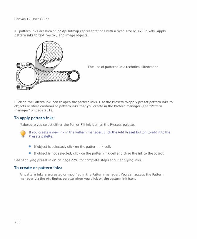
Canvas 12 User Guide
All pattern inks are bicolor 72 dpi bitmap representations with a fixed size of 8 x 8 pixels. Applypattern inks to text, vector, and image objects.
The use of patterns in a technical illustration
Click on the Pattern ink icon to open the pattern inks. Use the Presets to apply preset pattern inks toobjects or store customized pattern inks that you create in the Pattern manager (see "Patternmanager" on page 251).
To apply pattern inks:
Make sure you select either the Pen or Fill ink icon on the Presets palette.
If you create a new ink in the Pattern manager, click the Add Preset button to add it to thePresets palette.
If object is selected, click on the pattern ink cell.
If object is not selected, click on the pattern ink cell and drag the ink to the object.
See "Applying preset inks" on page 229, for complete steps about applying inks.
To create or pattern inks:
All pattern inks are created or modified in the Pattern manager. You can access the Patternmanager via the Attributes palette when you click on the pattern ink icon.
250
Chapter 3: Objects And Attributes
Pattern manager
Pencil tool Color the cells within the Edit box.
Move tool Click within the Edit box to see other parts of the pattern.
Switch Backgroundand Foregroundcolors
Click this button to switch the colors.
Edit box Create and modify patterns in this box. Changes appear in the Previewbox.
Preview box Patterns are displayed in this box while being modified.
Background andForeground color
Choose foreground and background colors from a color palette or createa custom color (see "Color Editor dialog box" on page 237).
Grayscale slider Increase grayscale to use more foreground or decrease it to use morebackground.
Add Preset Click this button to add the new ink to the Presets palette.
Creating favorite inks
Favorites inks allows you to easily build and retain a set of often used inks, whether they are color,gradient, texture, hatch, pattern, or symbol. You can create and save multiple palettes. Also, you canshare saved palettes with friends and co-workers for project consistency.
To add an ink to the Favorites inks:
1. If you wish to place an ink in the Favorite inks (e.g., a Pattern ink), click on the Pattern inkicon to view the Pattern inks palette.
2. Select the Pattern ink and then drag the ink cell to the Favorite inks icon. The Pattern ink isnow available on the Favorite inks palette. Once placed inside the Favorite inks, you can thenuse this ink at any time. Once you have placed several inks in the Favorite inks, you shouldsave the palette for future use.
To delete a Favorite ink:
Select the ink cell and drag it to the trash can.
251

Canvas 12 User Guide
To save a Favorite inks palette:
1. Click on the Favorite inks icon.
2. Open the Presets palette menu.
3. Select Save Favorites Inks.
4. Enter a file name and click Save.
Loading, appending, and clearing inks
You can load, and append inks for one ink type at a time in the Presets palette.
Load: Loads inks from a palette file, replacing the ink type currently open in the Presetspalette. In the dialog box, select a file and click Open.
Append: Adds inks from a palette file to the ink type currently open in the Presets palette. Inthe dialog box, select a palette file and click Open.
Clear: Removes the inks (except “no ink”) from the current palette.
Applying inks to objects
You can apply inks to two areas of vector objects and text:
Pen ink Ink used for the strokes of objects and text characters.
Fill ink Ink used for the interior of objects and text characters.
Objects can have different inks for a fill ink and a pen ink; e.g., a gradient fill and a pattern pen ink.In addition, you can apply inks to the backgrounds, outlines, and frame of text objects.
If an object has neither a pen ink nor a fill ink, the object is not visible.
Remember that you don’t apply inks to paint objects. Instead, use painting tools to paint in a paintobject and give it color (see "Painting & image-editing" on page 406).
Applying fill inks to open and closed paths
Whether a vector object path is open or closed affects the appearance of its fill ink. In a closed path,the ink completely fills the object’s interior; in an open path, the ink fills inside the path as if the path
252
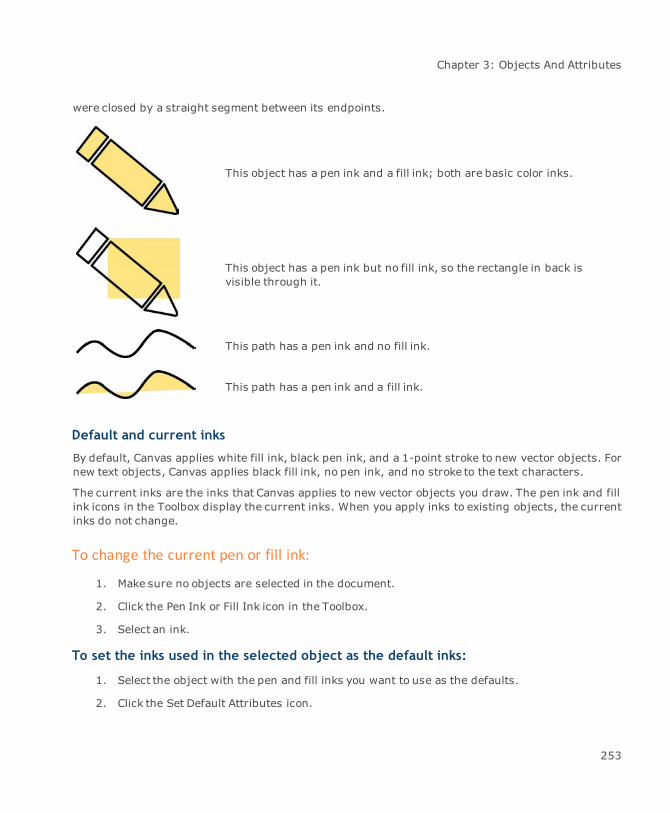
Chapter 3: Objects And Attributes
were closed by a straight segment between its endpoints.
This object has a pen ink and a fill ink; both are basic color inks.
This object has a pen ink but no fill ink, so the rectangle in back isvisible through it.
This path has a pen ink and no fill ink.
This path has a pen ink and a fill ink.
Default and current inks
By default, Canvas applies white fill ink, black pen ink, and a 1-point stroke to new vector objects. Fornew text objects, Canvas applies black fill ink, no pen ink, and no stroke to the text characters.
The current inks are the inks that Canvas applies to new vector objects you draw. The pen ink and fillink icons in the Toolbox display the current inks. When you apply inks to existing objects, the currentinks do not change.
To change the current pen or fill ink:
1. Make sure no objects are selected in the document.
2. Click the Pen Ink or Fill Ink icon in the Toolbox.
3. Select an ink.
To set the inks used in the selected object as the default inks:
1. Select the object with the pen and fill inks you want to use as the defaults.
2. Click the Set Default Attributes icon.
253

Canvas 12 User Guide
Using the Color Dropper
Use the Color Dropper tool to select and apply colors. The Color Dropper tool is located in the Toolbox.The Color Dropper can select colors from any object in a document.
Colors you select with the Color Dropper become the current foreground or background colors forpainting and the current pen inks and fill inks for new vector objects.
This tool helps keep color consistency within a document and is useful for photo retouching.It can also help identify colors from documents imported into Canvas.
To use the Color Dropper tool:
1. Click the Color Dropper in the Toolbox.
2. Click on the color in your document that you want to select.
Color Dropper modes
Select the Color Dropper tool to view the settings in the Properties bar. Select a mode. The moderemains set unless you change the setting in the Properties bar.
Object Ink In vector or text objects, the Color Dropper selects object inks —color,gradient, symbol, texture, pattern, and hatch inks. It does not take intoaccount transfer modes or transparency effects.
If you click an object’s stroke, you select its pen ink; if you click anobject’s interior, you select its fill ink. In the case of paint objects, whichdo not have inks, the color you click is selected as a color ink.
For example, if you click a gradient ink with the Color Dropper, it selectsthe gradient ink.
254
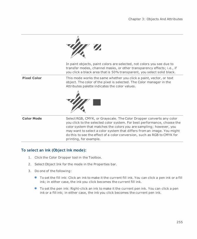
Chapter 3: Objects And Attributes
In paint objects, paint colors are selected, not colors you see due totransfer modes, channel masks, or other transparency effects; i.e., ifyou click a black area that is 50% transparent, you select solid black.
Pixel Color This mode works the same whether you click a paint, vector, or textobject. The color of the pixel is selected. The Color manager in theAttributes palette indicates the color values.
Color Mode Select RGB, CMYK, or Grayscale. The Color Dropper converts any coloryou click to the selected color system. For best performance, choose thecolor system that matches the colors you are sampling; however, youmay want to select a color system that differs from an image. You mightdo this to see the effect of a color conversion, such as RGB to CMYK forprinting, for example.
To select an ink (Object Ink mode):
1. Click the Color Dropper tool in the Toolbox.
2. Select Object Ink for the mode in the Properties bar.
3. Do one of the following:
To set the fill ink: Click an ink tomake it the current fill ink. You can click a pen ink or a fillink; in either case, the ink you click becomes the current fill ink.
To set the pen ink: Right-click an ink tomake it the current pen ink. You can click a penink or a fill ink; in either case, the ink you click becomes the current pen ink.
255

Canvas 12 User Guide
To select a color (Pixel Color mode):
1. Click the Color Dropper tool in the Toolbox.
2. Select Pixel Color for themode in the Properties bar.
3. Click a color to set the current fill ink color (vector and text objects) and background color(image objects). Right-click to set the current pen ink color (vector and text objects) andforeground color (image objects).
To select colors outside Canvas:
With the Color Dropper selected, drag from the Canvas window to anywhere on screen. As long asyou keep themouse button pressed, the Color Dropper remains active; the ink icons in theToolbox show you the colors the tool can select. Release the mouse button to select the colorunder the tip of the pointer.
While editing an image with a painting tool, you can quickly switch to the Color Dropper.Press Alt to display the Color Dropper, and click to select a foreground color for painting.
The color you select becomes the current fill ink and background color. You can’t use this method toselect the pen color.
To apply colors to vector and text objects:
Do one or more of the following:
To apply the current fill ink to the object, Ctrl-click a vector or text object.
To apply the current pen ink to the object, Ctrl-right-click a vector or text object.
The Color Dropper mode does not affect the application of colors. You cannot apply colors topaint objects using the Color Dropper tool.
Getting inks from vector and text objects
Canvas lets you add inks from vector objects and text objects to the Presets palette. If a text objectcontains both a text fill and a background fill, only the text fill will be added to the palette. You canalso add the inks of multiple selected objects; however, the inks from group objects and macroobjects cannot be added.
256

Chapter 3: Objects And Attributes
To add inks from objects to the Presets palette:
1. Select either the pen ink or fill ink icon on the Presets palette, depending on the type of inkyou want to add.
2. Drag the vector or text object onto the preset inks area of the appropriate ink type in thePresets palette; i.e., gradient inks only apply to the gradient ink type, hatch inks to the hatchink type, etc.
Replacing ink attributes
Canvas has a quick way to change all instances of a selected ink in a single document: the ReplaceInk Attributes command. This function can be applied to pen and fill inks for both vector and textobjects.
To replace an ink:
1. Choose Edit | Replace Ink Attributes.
2. In the Replace Ink dialog box, select the ink that you want to replace.
3. From the Replace With menu, select a replacement ink.
All the objects in the document using the selected ink are updated with the new ink.
4. Click OK to close the dialog box.
Strokes: outline effects
When you create objects with drawing tools, Canvas applies a stroke to the objects according toattributes set in the Presets palette. A stroke is a line centered on the path of vector objects and theoutlines of type. You can shape a stroke with standard and calligraphic pens, parallel lines, evenneon tubes. You can also add dashes and arrowheads to strokes.
This section explains basic stroke settings, how to customize strokes, and how to apply strokes toobjects and text.
Types of strokes
Canvas has five basic types of pen strokes, as well as arrows and dashes, which you can use tocreate unlimited variations.
Pen Strokes
The following types of strokes appear on Pen tab of the Presets palette.
257
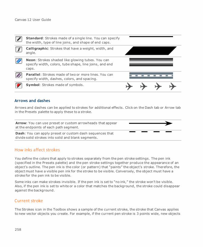
Canvas 12 User Guide
Standard: Strokes made of a single line. You can specifythe width, type of line joins, and shape of end caps.
Calligraphic: Strokes that have a weight, width, andangle.
Neon: Strokes shaded like glowing tubes. You canspecify width, colors, tube shape, line joins, and endcaps.
Parallel: Strokes made of two or more lines. You canspecify width, dashes, colors, and spacing.
Symbol: Strokes made of symbols.
Arrows and dashes
Arrows and dashes can be applied to strokes for additional effects. Click on the Dash tab or Arrow tabin the Presets palette to apply these to a stroke.
Arrow: You can use preset or custom arrowheads that appearat the endpoints of each path segment.
Dash: You can apply preset or custom dash sequences thatdivide solid strokes into solid and blank segments.
How inks affect strokes
You define the colors that apply to strokes separately from the pen stroke settings. The pen ink(specified in the Presets palette) and the pen stroke settings together produce the appearance of anobject’s outline. The pen ink is the color (or pattern) that “paints” the object’s stroke. Therefore, theobjectmust have a visible pen ink for the stroke to be visible. Conversely, the object must have astroke for the pen ink to be visible.
Some inks can make strokes invisible. If the pen ink is set to “no ink,” the stroke won’t be visible.Also, if the pen ink is set to white or a color that matches the background, the stroke could disappearagainst the background.
Current stroke
The Strokes icon in the Toolbox shows a sample of the current stroke, the stroke that Canvas appliesto new vector objects you create. For example, if the current pen stroke is 3 points wide, new objects
258

Chapter 3: Objects And Attributes
you draw will have a 3-pt pen stroke. Canvas does not apply the current stroke to text (see "Applyingstrokes to text" on page 259).
To change the current stroke:
1. Make sure no objects are selected in the document.
2. Click the Stroke icon in the Toolbox.
3. Select a stroke.
To change the stroke for a selected object:
1. Select an object.
2. Click the Stroke icon in the Toolbox.
3. Select a stroke.
When you first install Canvas, the current stroke defaults to a 1-pt pen stroke withoutdashes or arrowheads.
Applying strokes to text
You can apply strokes to text the same as to vector objects, in most cases. For information aboutselecting text objects and text characters, see "Formatting text" on page 577 and "Formatting textwith the Properties bar" on page 581).
When you first type or import text into a document, Canvas applies a black 1-point pen stroke to thetext, but does not assign a fill ink. You can apply pen, parallel, and neon strokes to text. You can alsoapply dashes to text that has a pen or neon stroke. If you select a text object, Canvas applies a stroketo all the text it contains. If you select specific characters within a text object, Canvas applies thestroke to those characters only.
259
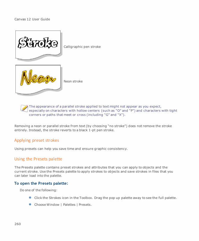
Canvas 12 User Guide
Calligraphic pen stroke
Neon stroke
The appearance of a parallel stroke applied to text might not appear as you expect,especially on characters with hollow centers (such as “O” and “P”) and characters with tightcorners or paths that meet or cross (including “G” and “X”).
Removing a neon or parallel stroke from text (by choosing “no stroke”) does not remove the strokeentirely. Instead, the stroke reverts to a black 1-pt pen stroke.
Applying preset strokes
Using presets can help you save time and ensure graphic consistency.
Using the Presets palette
The Presets palette contains preset strokes and attributes that you can apply to objects and thecurrent stroke. Use the Presets palette to apply strokes to objects and save strokes in files that youcan later load into the palette.
To open the Presets palette:
Do one of the following:
Click the Strokes icon in the Toolbox. Drag the pop up palette away to see the full palette.
ChooseWindow | Palettes | Presets.
260
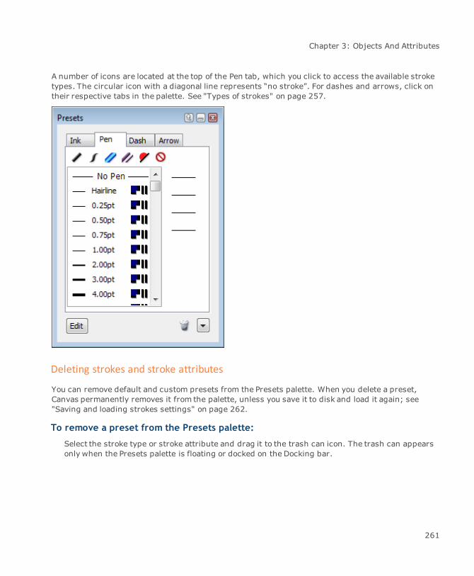
Chapter 3: Objects And Attributes
A number of icons are located at the top of the Pen tab, which you click to access the available stroketypes. The circular icon with a diagonal line represents “no stroke”. For dashes and arrows, click ontheir respective tabs in the palette. See "Types of strokes" on page 257.
Deleting strokes and stroke attributes
You can remove default and custom presets from the Presets palette. When you delete a preset,Canvas permanently removes it from the palette, unless you save it to disk and load it again; see"Saving and loading strokes settings" on page 262.
To remove a preset from the Presets palette:
Select the stroke type or stroke attribute and drag it to the trash can icon. The trash can appearsonly when the Presets palette is floating or docked on the Docking bar.
261
Canvas 12 User Guide
To remove all preset strokes or stroke attributes:
1. Select the stroke type or stroke attribute in the Presets palette.
2. Open the palette menu and choose Clear Palette Presets.
If you delete all arrowheads from the palette, dimension objects will not have arrows.
Saving and loading strokes settings
You can save preset strokes, arrows, and dashes in files on disk, and load the presets into thePresets palette. You can use these strokes files to customize the Presets palette for particularprojects or types of documents, and to exchange custom settings with other Canvas users.
Commands for saving and loading strokes files are in the Presets palette menu. The menu iconappears only when the Presets palette is separated from the Toolbox.
To save strokes in a file:
Use the following procedure to save the presets from one stroke type or stroke attribute in thePresets palette to a file on disk.
1. Open the Presets palette.
2. Click the Pen tab and select the stroke type. Or click on the Arrow or Dash tab for a strokeattribute.
3. Open the palette menu and select Save Presets. Themenu command will reflect the selectedstroke type or stroke attribute.
4. In the dialog box, enter a name for the file, select a location on a disk, and click Save.
To load strokes from a file:
Use the following procedure to load stroke types or stroke attributes that are stored in a file. Whenyou load a file, you can either replace the strokes that are presently in the Presets palette or simplyappend the stroke types or stroke attributes to the current ones.
1. Open the Presets palette.
2. Click the Pen tab and select the stroke type. Or click on the Arrow or Dash tab for a strokeattribute.
262

Chapter 3: Objects And Attributes
3. Open the palette menu and select Load Presets. Themenu command will reflect the selectedstroke type or stroke attribute.
4. In the dialog box, navigate to the file and click Open.
To apply preset strokes to objects:
Use the following general procedure to apply a preset stroke to one or more objects.
1. Select the objects for which you want to change strokes.
2. Click the Strokes icon in the Toolbox to open the Presets palette. The Pen tab will be selectedautomatically.
3. Select the stroke type.
4. Choose a stroke in the preset strokes list. If necessary, use the scroll bar or window resizebutton to view additional strokes. Canvas applies the stroke you choose to selected objects.
To make a preset stroke the current stroke:
Select a preset stroke as the current stroke to apply to new objects you create.
1. Deselect all objects in the current document. To deselect all objects, press Esc a few times.
2. Click the Strokes icon in the Toolbox to open the Presets palette. The Pen tab will be selectedautomatically.
3. Select the stroke type.
4. Choose a stroke in the preset strokes list. Use the scroll bar to view additional strokes. TheStrokes icon in the Toolbox shows the current stroke.
Using standard pen strokes
Themost common type of stroke is a standard pen stroke, a solid line of uniform width. This type ofstroke is used for many situations, such as technical illustrations, flowcharts, callout lines, etc.
By default, the width of pen strokes is measured in points (one point is 1/72 inch). Pen stroke widthsfrom 1 to 16 points appear in the Pen tab of the Presets palette.
To change the current pen stroke width:
1. Deselect all objects.
2. Open the Presets palette and click on the Pen tab.
263

Canvas 12 User Guide
3. Select the standard stroke type.
4. Select the pen strokewidth from the presets list.
To change the pen stroke width of specific objects:
Select one or more objects, then select a new pen stroke from the presets list for standardstrokes.
To change the ink of a pen stroke:
The color of a pen stroke comes from the object’s pen ink. The pen ink can be any of the available inktypes; i.e., gradient, pattern, symbol, color, hatch, or texture.
1. Select one or more objects whose pen ink you want to change.
2. Click the Pen Ink icon in the Toolbox. The Presets palette pops open with the Ink tab selected.Drag this palette away from the Toolbox to keep the Presets palette open as you work.
3. Select an ink type on the Ink tab. e.g. color, gradient, hatch, symbol, pattern, or texture (see"Inks: colors & patterns" on page 223).
‘Invisible’ inks
A pen ink is one or more colors that Canvas uses to apply color to pen strokes. The pen ink can be setto “no ink,” or to a color that blends into the background, which renders a pen stroke invisible.
In some situations, you might want to set an object’s pen ink to “no ink,” rather than remove theobject’s stroke. This can be useful to temporarily hide the stroke without removing the dash, arrow,and other stroke settings, for example.
To set an object’s pen ink to “no ink”:
This procedure removes the pen ink and makes the stroke invisible.
1. Select the object and click the Pen Ink icon to open the Presets palette with the Ink tabselected.
2. Click on the “no ink” icon.
Adding preset arrows to pen strokes
You can add arrowheads to pen, parallel, and neon strokes. You can apply strokes with arrows tolines and open paths, such as those created with the Curve tool. Arrowheads can appear at one orboth endpoints of a path.
264

Chapter 3: Objects And Attributes
You can also create custom arrowheads that you can add to the preset arrowheads (see "Creatingcustomarrowheads" on page 281).
To add arrows to strokes:
Use the following procedure to apply arrows to objects or the current stroke:
1. Depending on how you want arrows to apply, do one of the following:
To add an arrow to the current stroke: Deselect all objects.
To add arrows to specific objects’ strokes: Select the objects.
2. Click the Arrow icons in the Toolbox to open the popup Presets palette showing the differentarrowheads available.
The Arrow icons in the Toolbox let you choose between starting, ending, and double-sidedarrowheads.
265
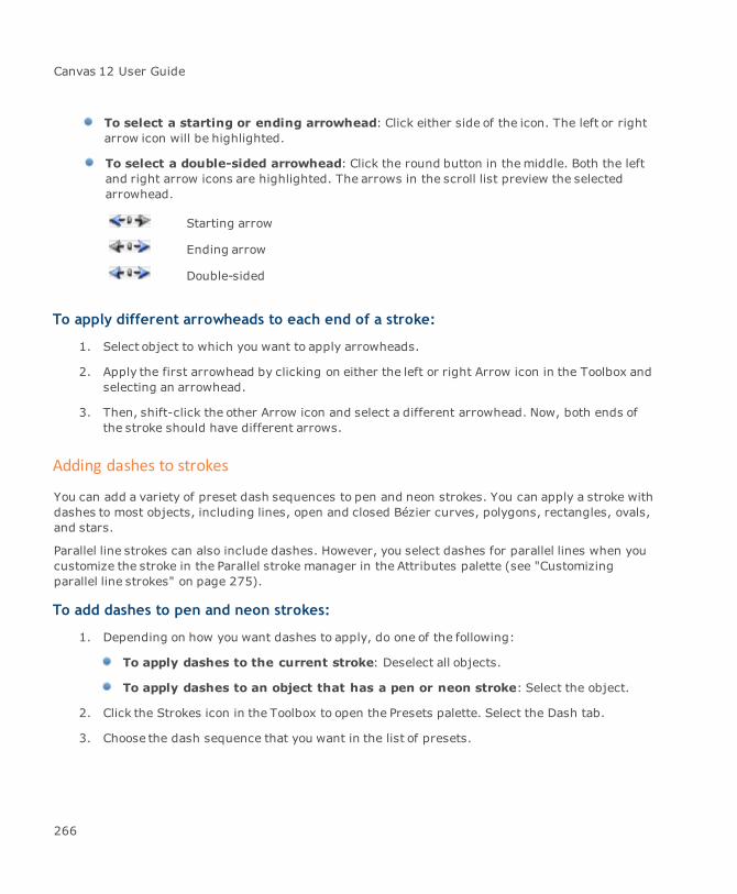
Canvas 12 User Guide
To select a starting or ending arrowhead: Click either side of the icon. The left or rightarrow icon will be highlighted.
To select a double-sided arrowhead: Click the round button in themiddle. Both the leftand right arrow icons are highlighted. The arrows in the scroll list preview the selectedarrowhead.
Starting arrow
Ending arrow
Double-sided
To apply different arrowheads to each end of a stroke:
1. Select object to which you want to apply arrowheads.
2. Apply the first arrowhead by clicking on either the left or right Arrow icon in the Toolbox andselecting an arrowhead.
3. Then, shift-click the other Arrow icon and select a different arrowhead. Now, both ends ofthe stroke should have different arrows.
Adding dashes to strokes
You can add a variety of preset dash sequences to pen and neon strokes. You can apply a stroke withdashes to most objects, including lines, open and closed Bézier curves, polygons, rectangles, ovals,and stars.
Parallel line strokes can also include dashes. However, you select dashes for parallel lines when youcustomize the stroke in the Parallel stroke manager in the Attributes palette (see "Customizingparallel line strokes" on page 275).
To add dashes to pen and neon strokes:
1. Depending on how you want dashes to apply, do one of the following:
To apply dashes to the current stroke: Deselect all objects.
To apply dashes to an object that has a pen or neon stroke: Select the object.
2. Click the Strokes icon in the Toolbox to open the Presets palette. Select the Dash tab.
3. Choose the dash sequence that you want in the list of presets.
266

Chapter 3: Objects And Attributes
Removing arrows, dashes, and strokes
You can remove a selected object’s stroke, or set the current stroke to “no stroke,” so you can createobjects that have no stroke. An object that has no stroke has no visible outline. Objects drawn withthe Line tool become invisible without a stroke; other objects are still visible if they have a visible fillink.
You can also remove dashes and arrows from a stroke. Because arrows and dashes are attributes ofstrokes, you can remove themwithout removing the entire stroke.
Removing arrows, dashes, and strokes involves the same procedure as changing from one presetstroke to another.
To remove arrows or dashes:
You can use the following procedure to remove arrows from pen, parallel, and neon strokes, and toremovedashes from pen and neon strokes. For details about removing dashes from parallel strokes,see "Customizing parallel line strokes" on page 275.
1. Depending on how you want to remove arrows or dashes, do one of the following:
To remove stroke attributes from an object: Select the object.
To remove stroke attributes from the current stroke: Deselect all objects.
2. Click the Strokes icon in the Toolbox to open the Presets palette. Choose the Dash or Arrowtab, depending on the attribute you want to remove.
3. Choose “no arrow” on the Arrow tab to remove arrows from a stroke. Choose “no dash” on theDash tab to remove dashes.
To use “no stroke” settings:
Remove strokes entirely from objects, or use “no stroke” as the current setting for new objects.
1. Depending on how you want to remove strokes, do one of the following:
To remove the stroke from an object: Select the object.
To make “no stroke” the current setting: Deselect all objects.
2. Click the Strokes icon in the Toolbox and choose “no stroke” on the Pen tab.
Applying tapered ends to standard and neon strokes
This option can be applied to standard pen strokes and neon strokes; however, it is best viewedwhen a pen setting is larger than 3.00 pt.
267
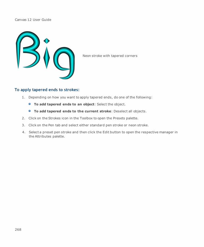
Canvas 12 User Guide
Neon stroke with tapered corners
To apply tapered ends to strokes:
1. Depending on how you want to apply tapered ends, do one of the following:
To add tapered ends to an object: Select the object.
To add tapered ends to the current stroke: Deselect all objects.
2. Click on the Strokes icon in the Toolbox to open the Presets palette.
3. Click on the Pen tab and select either standard pen stroke or neon stroke.
4. Select a preset pen stroke and then click the Edit button to open the respective manager inthe Attributes palette.
268

Chapter 3: Objects And Attributes
Use the Tapered End controlsin the Standard Pen Strokemanager.
Select from no taper, end-to-end taper, left taper, and righttaper.
269
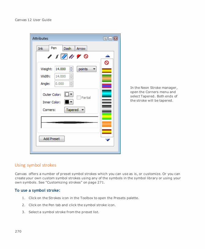
Canvas 12 User Guide
In the Neon Stroke manager,open the Corners menu andselect Tapered. Both ends ofthe stroke will be tapered.
Using symbol strokes
Canvas offers a number of preset symbol strokes which you can use as is, or customize. Or you cancreate your own custom symbol strokes using any of the symbols in the symbol library or using yourown symbols. See "Customizing strokes" on page 271.
To use a symbol stroke:
1. Click on the Strokes icon in the Toolbox to open the Presets palette.
2. Click on the Pen tab and click the symbol stroke icon.
3. Select a symbol stroke from the preset list.
270
Chapter 3: Objects And Attributes
Customizing strokes
You can customize strokes in the Attributes palette:
Display the strokes settings of selected objects.
Create custom pen, parallel, calligraphic, and neon strokes.
Create custom arrowheads and dash sequences.
Apply custom settings to objects or the current stroke.
Store custom strokes as presets in the palette.
Using the Attributes palette
To open the Attributes palette:
1. Do one of the following:
Click the Stroke icon in the Toolbox to open the Presets palette, then click the Edit button.
ChooseWindow | Palettes | Attributes.
2. Select the stroke type or stroke attribute that you want to define.
To use a preset stroke as the basis for a custom setting:
1. In the Presets palette, select a stroke, then click the Edit button.
2. Select an object in your document.
3. In the Attributes palette, adjust the stroke settings.
4. If you want to save the custom settings as a preset, click the Add Preset button.
To add custom settings:
1. In the Attributes palette, specify the custom settings.
2. Click the Add Preset button.
The new stroke or stroke attribute is added to the appropriate stroke type or tab in thePresets palette.
271
Canvas 12 User Guide
To add settings from an object to the palette:
1. ChooseWindow | Palettes | Attributes.
2. Select an object.
The respective stroke type manager or stroke attribute tab opens in the Attributes palette.
3. Click the Add Preset button.
When you end a Canvas session, the program stores the stroke type and attribute presets with theprogram.The same presets are available, whether you work with new documents, documents youcreated, or documents created by another Canvas user.
If you create a custom stroke and want to apply it to more than one object, and especially if you wantto use it in a later work session, you should add the custom settings to the Presets palette.
Customizing standard & calligraphic strokes
If you want to create custom standard pen or calligraphic strokes, use the respective manager in theAttributes palette.
Standard pen strokes have a uniform weight, specified offset, and may have tapered ends.Calligraphic pen strokes have a separate width, weight, and angle setting. For both stroke types, youcan define the line joins (bevel, miter, or round) and end caps (flat, round, or square).
For basic information about setting pen size, see "Using standard pen strokes" on page 263.
You can choose another unit of measurement instead of points as the pen size unit using theunit menu in the Attributes palette.
To create a standard pen:
1. Click on the Pen tab of the Attributes palette.
2. Select the standard pen stroke type to access its respective manager.
3. Use the standard stroke manager controls to define the new stroke.
4. Click the Add Preset button to add this new stroke to the Presets palette.
Standard pen stroke controls
Use these options to define standard strokes.
272
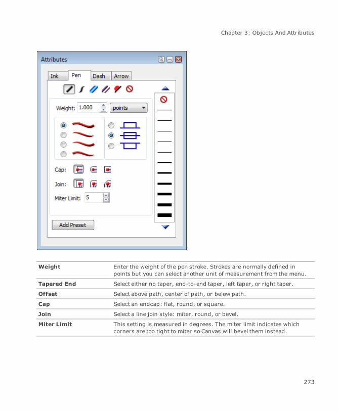
Chapter 3: Objects And Attributes
Weight Enter the weight of the pen stroke. Strokes are normally defined inpoints but you can select another unit of measurement from the menu.
Tapered End Select either no taper, end-to-end taper, left taper, or right taper.
Offset Select above path, center of path, or below path.
Cap Select an endcap: flat, round, or square.
Join Select a line join style: miter, round, or bevel.
Miter Limit This setting is measured in degrees. The miter limit indicates whichcorners are too tight to miter so Canvas will bevel them instead.
273
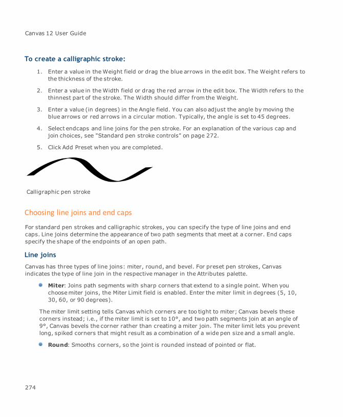
Canvas 12 User Guide
To create a calligraphic stroke:
1. Enter a value in theWeight field or drag the blue arrows in the edit box. The Weight refers tothe thickness of the stroke.
2. Enter a value in theWidth field or drag the red arrow in the edit box. The Width refers to thethinnest part of the stroke. The Width should differ from the Weight.
3. Enter a value (in degrees) in the Angle field. You can also adjust the angle by moving theblue arrows or red arrows in a circular motion. Typically, the angle is set to 45 degrees.
4. Select endcaps and line joins for the pen stroke. For an explanation of the various cap andjoin choices, see "Standard pen stroke controls" on page 272.
5. Click Add Preset when you are completed.
Calligraphic pen stroke
Choosing line joins and end caps
For standard pen strokes and calligraphic strokes, you can specify the type of line joins and endcaps. Line joins determine the appearance of two path segments that meet at a corner. End capsspecify the shape of the endpoints of an open path.
Line joins
Canvas has three types of line joins: miter, round, and bevel. For preset pen strokes, Canvasindicates the type of line join in the respective manager in the Attributes palette.
Miter: Joins path segments with sharp corners that extend to a single point. When youchoosemiter joins, the Miter Limit field is enabled. Enter the miter limit in degrees (5, 10,30, 60, or 90 degrees).
Themiter limit setting tells Canvas which corners are too tight to miter; Canvas bevels thesecorners instead; i.e., if themiter limit is set to 10°, and two path segments join at an angle of9°, Canvas bevels the corner rather than creating a miter join. The miter limit lets you preventlong, spiked corners that might result as a combination of a wide pen size and a small angle.
Round: Smooths corners, so the joint is rounded instead of pointed or flat.
274
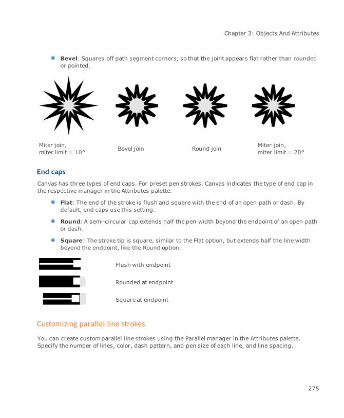
Chapter 3: Objects And Attributes
Bevel: Squares off path segment corners, so that the joint appears flat rather than roundedor pointed.
Miter join,miter limit = 10° Bevel join Round join Miter join,
miter limit = 20°
End caps
Canvas has three types of end caps. For preset pen strokes, Canvas indicates the type of end cap inthe respective manager in the Attributes palette.
Flat: The end of the stroke is flush and square with the end of an open path or dash. Bydefault, end caps use this setting.
Round: A semi-circular cap extends half the pen width beyond the endpoint of an open pathor dash.
Square: The stroke tip is square, similar to the Flat option, but extends half the line widthbeyond the endpoint, like the Round option.
Flush with endpoint
Rounded at endpoint
Square at endpoint
Customizing parallel line strokes
You can create customparallel line strokes using the Parallel manager in the Attributes palette.Specify the number of lines, color, dash pattern, and pen size of each line, and line spacing.
275
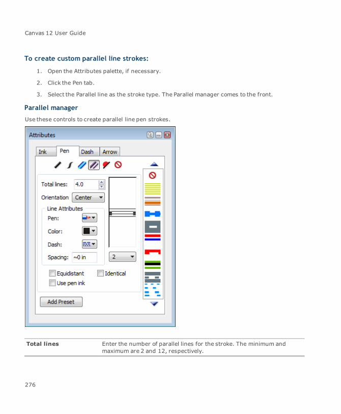
Canvas 12 User Guide
To create custom parallel line strokes:
1. Open the Attributes palette, if necessary.
2. Click the Pen tab.
3. Select the Parallel line as the stroke type. The Parallel manager comes to the front.
Parallel manager
Use these controls to create parallel line pen strokes.
Total lines Enter the number of parallel lines for the stroke. The minimum andmaximum are 2 and 12, respectively.
276
Chapter 3: Objects And Attributes
Orientation Specify the placement of parallel lines relative to the object’s path.ChooseCenter, Outside, or Inside.
Line Attributes Use these controls to define the appearance of the stroke.
Pen: Select a pen width from the palette.Color: Select a color from the palette. You can also specify custompen colors (see"The color editor" on page 235).Dash: Select a dash if you want the stroke to contain one.Spacing: Enter a number to specify the distance between theselected line and the one below it. For Line #1, this setting definesthe space between this line and Line #2. Choose a number from themenu to edit the line. Line #1 corresponds to the bottom line. Youcan also click a line in the edit box to select it. The selected line isindicated with handles.
Equidistant Turn on this option to apply the spacing setting for the selected line to alllines.
Use pen ink Turn on this option to apply a color to the spaces between the parallellines.
Identical Turn on this option to give all parallel lines the same appearance (penwidth, color, and dash).
Add Preset Click the Add Preset button when you have finished defining the stroke.
Customizing neon strokes
You can create customneon strokes using the Neon manager in the Attributes palette. Specify thewidth, colors, line joins, and end caps as well as create uniform and calligraphic neon strokes.
Tomake the stroke appear round, experiment with lighter inside colors and darker outsidecolors.
To create custom neon strokes:
1. Open the Attributes palette and select the Pen tab.
2. Select the Neon pen stroke type.
3. Use the Neon manager to define either a standard pen stroke or calligraphic stroke.
277
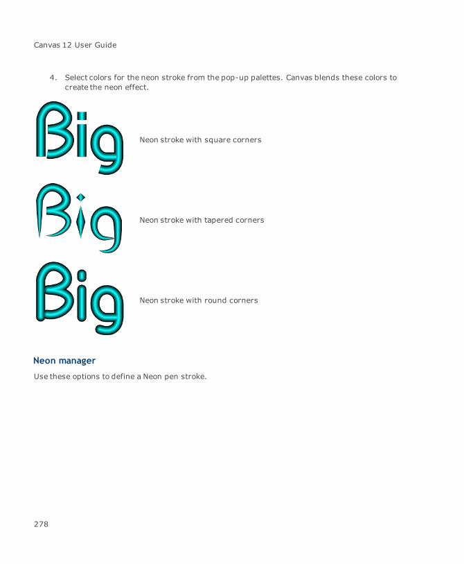
Canvas 12 User Guide
4. Select colors for the neon stroke from the pop-up palettes. Canvas blends these colors tocreate the neon effect.
Neon stroke with square corners
Neon stroke with tapered corners
Neon stroke with round corners
Neon manager
Use these options to define a Neon pen stroke.
278

Chapter 3: Objects And Attributes
Weight Enter a value in theWeight field. The Weight refers to the thickness ofthe stroke.
Width Enter a value in theWidth field. The Width refers to the thinnest part ofthe stroke. For a standard stroke, the Width is equal to the Weight. For acalligraphic effect, the Width should differ from the Weight.
Angle Enter a value (in degrees) in the Angle field. For a calligraphic stroke,the angle is typically set to 45°.
Outer Color Select the color for the exterior portion of the neon stroke.
Partial Select this check box to give the stroke a gradient effect.
Inner Color Select the color for the interior portion of the neon stroke.
Corners Define the appearance of the stroke’s corners: Round, Square, orTapered.
279
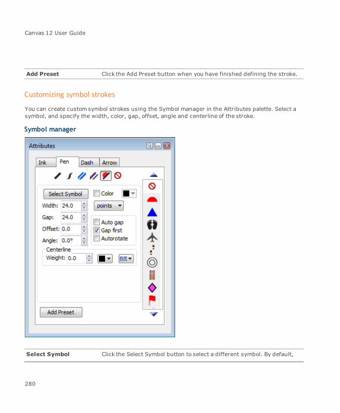
Canvas 12 User Guide
Add Preset Click the Add Preset button when you have finished defining the stroke.
Customizing symbol strokes
You can create customsymbol strokes using the Symbol manager in the Attributes palette. Select asymbol, and specify the width, color, gap, offset, angle and centerline of the stroke.
Symbol manager
Select Symbol Click the Select Symbol button to select a different symbol. By default,
280
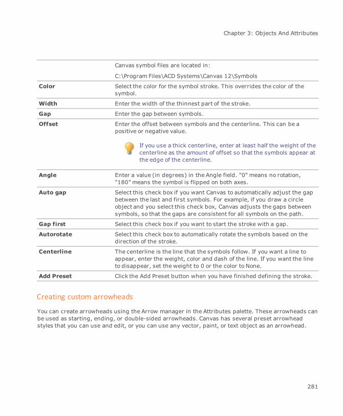
Chapter 3: Objects And Attributes
Canvas symbol files are located in:
C:\Program Files\ACD Systems\Canvas 12\Symbols
Color Select the color for the symbol stroke. This overrides the color of thesymbol.
Width Enter the width of the thinnest part of the stroke.
Gap Enter the gap between symbols.
Offset Enter the offset between symbols and the centerline. This can be apositive or negative value.
If you use a thick centerline, enter at least half the weight of thecenterline as the amount of offset so that the symbols appear atthe edge of the centerline.
Angle Enter a value (in degrees) in the Angle field. "0" means no rotation,"180" means the symbol is flipped on both axes.
Auto gap Select this check box if you want Canvas to automatically adjust the gapbetween the last and first symbols. For example, if you draw a circleobject and you select this check box, Canvas adjusts the gaps betweensymbols, so that the gaps are consistent for all symbols on the path.
Gap first Select this check box if you want to start the stroke with a gap.
Autorotate Select this check box to automatically rotate the symbols based on thedirection of the stroke.
Centerline The centerline is the line that the symbols follow. If you want a line toappear, enter the weight, color and dash of the line. If you want the lineto disappear, set the weight to 0 or the color to None.
Add Preset Click the Add Preset button when you have finished defining the stroke.
Creating custom arrowheads
You can create arrowheads using the Arrow manager in the Attributes palette. These arrowheads canbe used as starting, ending, or double-sided arrowheads. Canvas has several preset arrowheadstyles that you can use and edit, or you can use any vector, paint, or text object as an arrowhead.
281
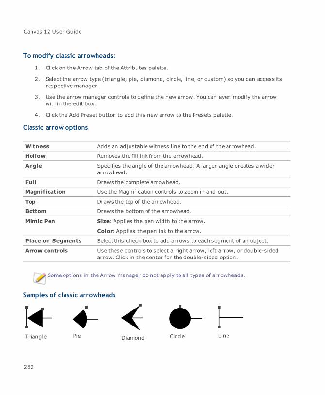
Canvas 12 User Guide
To modify classic arrowheads:
1. Click on the Arrow tab of the Attributes palette.
2. Select the arrow type (triangle, pie, diamond, circle, line, or custom) so you can access itsrespective manager.
3. Use the arrow manager controls to define the new arrow. You can even modify the arrowwithin the edit box.
4. Click the Add Preset button to add this new arrow to the Presets palette.
Classic arrow options
Witness Adds an adjustable witness line to the end of the arrowhead.
Hollow Removes the fill ink from the arrowhead.
Angle Specifies the angle of the arrowhead. A larger angle creates a widerarrowhead.
Full Draws the complete arrowhead.
Magnification Use the Magnification controls to zoom in and out.
Top Draws the top of the arrowhead.
Bottom Draws the bottom of the arrowhead.
Mimic Pen Size: Applies the pen width to the arrow.
Color: Applies the pen ink to the arrow.
Place on Segments Select this check box to add arrows to each segment of an object.
Arrow controls Use these controls to select a right arrow, left arrow, or double-sidedarrow. Click in the center for the double-sided option.
Some options in the Arrow manager do not apply to all types of arrowheads.
Samples of classic arrowheads
Triangle Pie Diamond Circle Line
282
Chapter 3: Objects And Attributes
To create a custom arrowhead:
1. In the Attributes palette, select Custom from the Type menu.
2. Select the Arrow settings you want to use.
3. Click the Add Preset button to add the custom arrow to the Presets palette.
Custom arrow options
Type Select Custom from the menu.
Flip Click the buttons to flip the arrow horizontally and vertically.
Create Click the Create button and the object appears in the edit box.
Edit box Modify the arrowhead in this box. Drag the handles to resize thearrowhead. A horizontal line indicates the horizontal axis of the path'sendpoint. A vertical line indicates the vertical axis of the path's endpoint.
Mimic Pen Size: Applies the pen width to the arrow.
Color: Applies the pen ink to the arrow.
Place on Segments Select this check box to add arrows to each segment of an object.
Arrow controls Use these controls to select a right arrow, left arrow, or double-sidedarrow. Click in the center for the double-sided option.
Customizing dashes
Dashes are composed of alternating solid and blank segments. Using the Dash manager, you cancustomize the length of up to 13 segments to create new, complex dash sequences.
Dash stroke
You can design dashes interactively using the edit window. To precisely set the length of each dashsegment, you can also specify an exact length. The ruler in the Dash manager displays inches;however, you can enter dash lengths in any unit of measurement available.
Dashes in the Presets palette always appear as 1-point wide, black and white segments. However,when you apply these dashes to an object’s pen, the black segments adopt the color and size of thepen, and the white segments become transparent.
283
Canvas 12 User Guide
To create a dash:
1. Click on the Dash tab of the Attributes palette.
2. Use the dash manager controls to define the new dash.
3. Click the Add Preset button to the new dash to the Presets palette.
Creating custom dashes
Use these options to create a custom dash for your stroke.
Dash/Gap controls Enter the size of the dashes and gaps in points.
Proportional Tells Canvas to scale the length of the segments tomatch the pen widthof the object. The length of segments in the Dash manager are based ona 1-point line. Therefore, if the pen width is 6 points and Proportional isselected, Canvas multiplies the lengths by six.
Preview box Displays a sample of the dash.
Magnification Use the Magnification controls to zoom in and out. To zoomout, click theleft button. To zoom in, click the right button. Select the Magnificationcheck box to enable the Magnification area.
Edit box Select a segment, indicated by a double-arrow.
Edit the segment by dragging the double-arrow.
The dash/gap length is indicated in the Length box.
Length Enter a precise length for the selected segment in points.
Segment Shows the selected segment’s number (its order in the sequence) andits color. “Black” indicates it will use the pen ink. “White” means thesegment will be transparent (a gap).
284
Chapter 4: Drawing And Vector Effects
Canvas 12 User Guide
Drawing basics
This section describes how to draw and resize vector objects. The Canvas drawing tools let you easilydraw basic shapes—lines, rectangles, ovals, and arcs — and create precise squares, circles, andstraight lines. Specialized tools let you draw grids, stars, polygons, concentric circles, cubes, andspirals.
Drawing basic shapes
In Canvas you can quickly draw simple shapes using the following drawing tools:
Line
Rectangle
Oval
Each of these tools belongs to a tool palette containing additional similar drawing tools.
To open a tool palette:
Click a tool in the Toolbox.
To float a tool palette:
Press Shift and drag the tool palette away from the Toolbox.
Drawing lines, rectangles, squares, ovals, circles, and arcs
To draw simple lines, rectangles, squares, ovals, circles, and arcs:
1. Click one of the drawing tools in the Toolbox.
2. Click in your document and drag to draw the shape (or press Shift and drag).
286
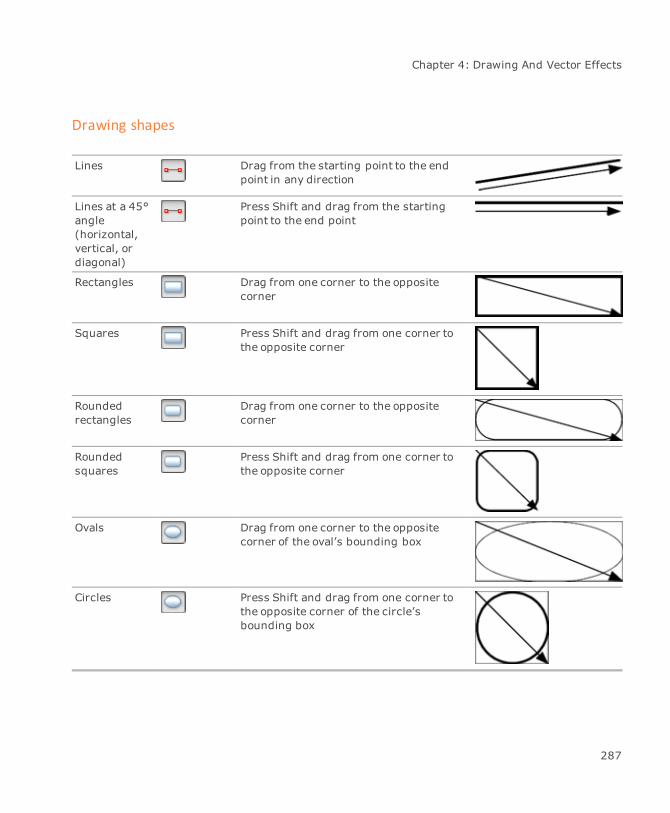
Chapter 4: Drawing And Vector Effects
Drawing shapes
Lines Drag from the starting point to the endpoint in any direction
Lines at a 45°angle(horizontal,vertical, ordiagonal)
Press Shift and drag from the startingpoint to the end point
Rectangles Drag from one corner to the oppositecorner
Squares Press Shift and drag from one corner tothe opposite corner
Roundedrectangles
Drag from one corner to the oppositecorner
Roundedsquares
Press Shift and drag from one corner tothe opposite corner
Ovals Drag from one corner to the oppositecorner of the oval’s bounding box
Circles Press Shift and drag from one corner tothe opposite corner of the circle’sbounding box
287

Canvas 12 User Guide
Arcs Drag from one corner to the oppositecorner of the arc’s bounding box
Circle-segment arcs
Press Shift and drag from one corner tothe opposite corner of the arc’s boundingbox
When you draw a vector object, Canvas applies the current ink and stroke settings. The inksand stroke icons in the Toolbox show a preview of the current settings. You can changethese attributes before or after you draw an object (see "Inks: colors & patterns" on page223 and "Strokes: outline effects" on page 257).
Drawing objects from the center
You can draw many vector objects starting from the object’s center rather than an edge.
To draw an object from the center:
Position the cursor where you want the object’s center to be, then press Ctrl and drag away fromthe center to draw the object.
When you draw an object from the center, you can also press Shift at the same time if youwant to also constrain the object’s bounding box to a square. Use this technique to draw aperfect square or circle from the center outward.
Drawing circles
As well as drawing basic circles, you can draw circles by 3 points or by radius. The Circle 3 Pointstool draws a circle through three points that you set. The Circle Radius tool draws a circle from acenter point and a radius that you set. Both tools draw circles with the current fill ink, pen ink, andstroke.
The Circle Radius and Circle 3 Points tools are located in the Oval tool palette.
288
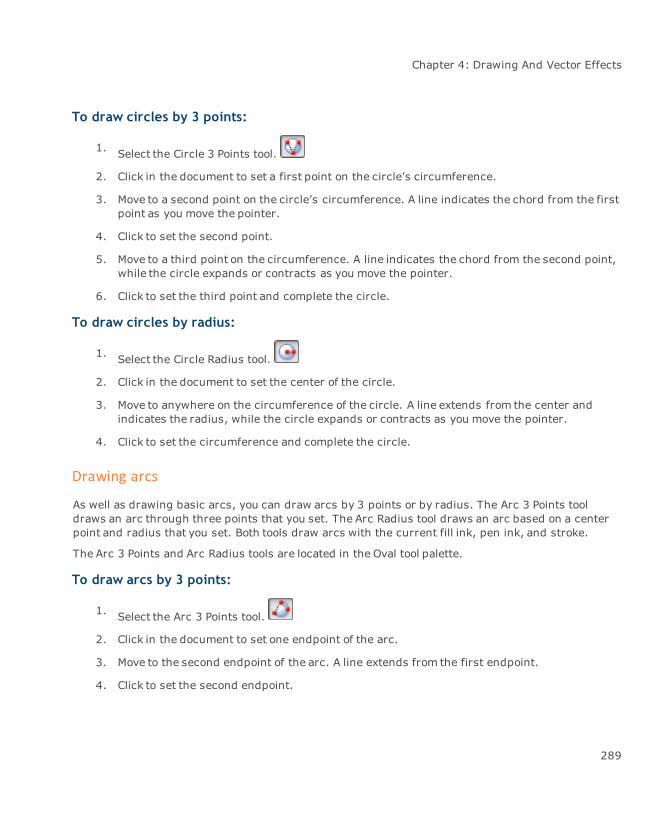
Chapter 4: Drawing And Vector Effects
To draw circles by 3 points:
1. Select the Circle 3 Points tool.
2. Click in the document to set a first point on the circle’s circumference.
3. Move to a second point on the circle’s circumference. A line indicates the chord from the firstpoint as you move the pointer.
4. Click to set the second point.
5. Move to a third point on the circumference. A line indicates the chord from the second point,while the circle expands or contracts as you move the pointer.
6. Click to set the third point and complete the circle.
To draw circles by radius:
1. Select the Circle Radius tool.
2. Click in the document to set the center of the circle.
3. Move to anywhere on the circumference of the circle. A line extends from the center andindicates the radius, while the circle expands or contracts as you move the pointer.
4. Click to set the circumference and complete the circle.
Drawing arcs
As well as drawing basic arcs, you can draw arcs by 3 points or by radius. The Arc 3 Points tooldraws an arc through three points that you set. The Arc Radius tool draws an arc based on a centerpoint and radius that you set. Both tools draw arcs with the current fill ink, pen ink, and stroke.
The Arc 3 Points and Arc Radius tools are located in the Oval tool palette.
To draw arcs by 3 points:
1. Select the Arc 3 Points tool.
2. Click in the document to set one endpoint of the arc.
3. Move to the second endpoint of the arc. A line extends from the first endpoint.
4. Click to set the second endpoint.
289

Canvas 12 User Guide
5. Move to a point on the perimeter of the arc. A line indicates the chord from the second point,while the arc expands or contracts as you move the pointer.
6. Click to set the perimeter point and finish the arc.
To draw arcs by radius:
1. Select the Arc Radius tool.
2. Click in the document to set the center of the arc.
3. Move to one endpoint of the arc. A line extends from the center and indicates the arc’sradius.
4. Click to set the endpoint.
5. Move to the second endpoint of the arc. An arc segment extends from the first endpoint andindicates the arc’s length.
6. Click to set the second endpoint and finish the arc.
To change the length of an arc:
1. Select the arc. Round handles appear near the beginning and end of the arc segment.
2. To adjust the length of the arc, do one of the following:
To shorten the arc, drag the round handle back over the arc.
To lengthen the arc, drag the round handle to continue the arc segment.
You can also adjust the length of an arc by changing its Start angle and values in the Properties baror Object Specs palette.
To change the corner radius of a rounded rectangle:
1. Select the rounded rectangle. A round handle appears near the lower-right corner of therectangle.
2. Drag the handle to change the corner diameter.
You can also adjust the corner radius in the Properties bar or use the Diag setting in the ObjectSpecs palette.
290

Chapter 4: Drawing And Vector Effects
Resizing and reshaping vector objects
You can resize and reshape a vector object by changing the size and shape of the object’s boundingbox. You can also change the length of arc segments and the corner radius of rounded rectangles.These techniques are described in the following section.
You can also edit most vector objects by changing the anchor points and segments that form theirpaths. For information on these editing techniques, see "Editing object paths" on page 324.
To resize an object’s bounding box:
When you drag a handle on a vector object’s bounding box, you change the height or width (or both)of the bounding box. This also changes the size (and possibly the shape) of the object; e.g., if youselect a circle and drag a side handle tomake the bounding box wider, the circle becomes an ovalthat is wider than it is tall.
1. Choose a Selection tool.
Use the filled arrow to select a single object (including a group object).
Use the hollow arrow to select an individual object within a group object.
2. Click the object to select it. Handles appear on the object’s bounding box.
3. Drag a handle, as described below, to resize the object.
To change Do this
Height Drag the top or bottom handle
Width Drag a side handle
Height and width Drag a corner handle
Height and widthproportionally
Press Shift and drag a corner handle
Symmetrically (from center) Press Ctrl and drag a handle
Symmetrically andproportionally
Press Ctrl-Shift and drag a corner handle
Maintaining object proportions
When you resize vector objects and want tomaintain the object’s height-to-width ratio, you have thefollowing options:
291
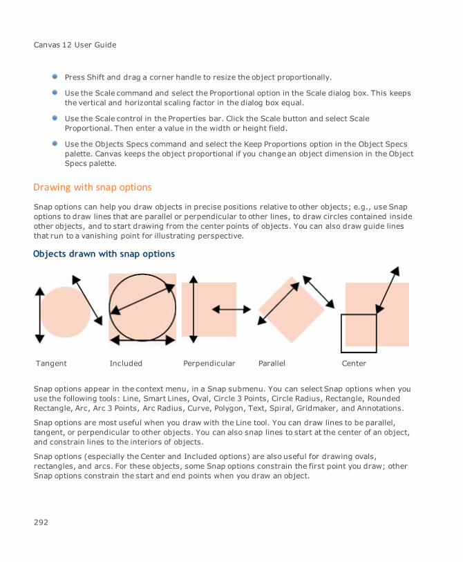
Canvas 12 User Guide
Press Shift and drag a corner handle to resize the object proportionally.
Use the Scale command and select the Proportional option in the Scale dialog box. This keepsthe vertical and horizontal scaling factor in the dialog box equal.
Use the Scale control in the Properties bar. Click the Scale button and select ScaleProportional. Then enter a value in the width or height field.
Use the Objects Specs command and select the Keep Proportions option in the Object Specspalette. Canvas keeps the object proportional if you change an object dimension in the ObjectSpecs palette.
Drawing with snap options
Snap options can help you draw objects in precise positions relative to other objects; e.g., use Snapoptions to draw lines that are parallel or perpendicular to other lines, to draw circles contained insideother objects, and to start drawing from the center points of objects. You can also draw guide linesthat run to a vanishing point for illustrating perspective.
Objects drawn with snap options
Tangent Included Perpendicular Parallel Center
Snap options appear in the context menu, in a Snap submenu. You can select Snap options when youuse the following tools: Line, Smart Lines, Oval, Circle 3 Points, Circle Radius, Rectangle, RoundedRectangle, Arc, Arc 3 Points, Arc Radius, Curve, Polygon, Text, Spiral, Gridmaker, and Annotations.
Snap options are most useful when you draw with the Line tool. You can draw lines to be parallel,tangent, or perpendicular to other objects. You can also snap lines to start at the center of an object,and constrain lines to the interiors of objects.
Snap options (especially the Center and Included options) are also useful for drawing ovals,rectangles, and arcs. For these objects, some Snap options constrain the first point you draw; otherSnap options constrain the start and end points when you draw an object.
292

Chapter 4: Drawing And Vector Effects
To use snap options:
1. Select the Line tool or another tool (the available tools are listed previously).
2. Point to the object to which you want to snap. (To use the Vanishing Point option, skip thisstep; you do not need to point to an object.)
To draw parallel to a line: Place the pointer anywhere on the line.
To draw parallel to a rectangle or polygon: Point to the side to which you want todraw parallel.
To draw perpendicular to an object: Point to the side to which you want to drawperpendicular.
To snap to the center of an object: Place the pointer anywhere inside the object.
3. Right-click to open the context menu and choose an option (described below) in the Snapsubmenu.
4. If you chose Parallel or Perpendicular, a reference line appears. Move themouse and thenclick to set the reference line.
For the Parallel option, in the dialog box, accept or change the indicated offset from theobject, and then click OK to continue.
5. Move the pointer to where you want to start drawing. Depending on the tool you are using,either drag to draw an object, or click to set the points of the object.
Objects that should be two-dimensional might appear one- dimensional if you try to drawusing certain Snap options; e.g., if you snap a rectangle to a line using the Included option,two opposite corners of the rectangle will snap to the line. If the line is vertical or horizontal,the rectangle will appear as a line.
Snap submenu options
To choose a Snap option, make sure the pointer is on the object or the object side that you want touse as a reference, then open the context menu and choose an option in the Snap submenu.
Parallel: Lets you set a reference line parallel to a line or the side of an object. Afterselecting this option, move the mouse to position the reference line, then click to set it. In thedialog box that appears, you can enter the distance you want the reference line to be offsetfrom the object. Click OK to continue. Begin drawing and the object will snap to the referenceline.
293
Canvas 12 User Guide
Perpendicular: Lets you set a reference line perpendicular to a line or the side of an object.After selecting this option, move the mouse to position the reference line, then click to set it.Begin drawing and the object will snap to the reference line.
Tangent: Lets you set a reference line tangent to a circle, an oval, or an arc. After selectingthis option, move themouse to position the reference line, then click to set it. Begin drawingand the object will snap to the reference line.
Included: Snaps an object’s start and end points to the outline of an object or to a line. Forexample, you can use this option to snap the bounding box of a circle to the inside of arectangle.
Center: Snaps the first point you draw to the center of an object or a line.
Vanishing Point: Snaps the first point of an object to the document’s vanishing point. Ifyou draw with the Line tool, the line will snap to the vanishing point and run to the location ofthe pointer when you begin dragging.
You can draw perspective lines with the Vanishing Point option, and make the lines intoalignment guides with the Object | Make Guide command.
There is one global vanishing point in a document. The vanishing point is used by the commands inthe Effects | Perspective submenu as well as the Snap | Vanishing Point command. The defaultvanishing point is at ruler coordinates 0,0. You can use the Effects | Perspective | Vanishing Pointcommand to apply perspective to selected objects and establish the vanishing point. Using the 1 Sideand 2 Sides commands will also affect the location of the document’s vanishing point.
Drawing by numbers
Several drawing tools give you the option of entering dimensions to draw objects precisely. Thismethod can be easier than dragging the mouse and watching data in the Properties bar to drawobjects to precise dimensions.
You can enter dimensions in the Properties bar when you use the Oval, Arc, Rectangle, RoundedRectangle, Line, Annotations, Multigon, Concentric Circles, and Spiral tools. You can enter the X/Ycoordinates, width, height, or other values, and then click Create in the Properties bar to draw theobject. With these tools, you can still drag the mouse to draw interactively.
You can also enter values in the Properties bar for some Path tools.
You can also establish precise dimensions and locations for any object in a document withthe Data tab in the Object Specs palette.
294
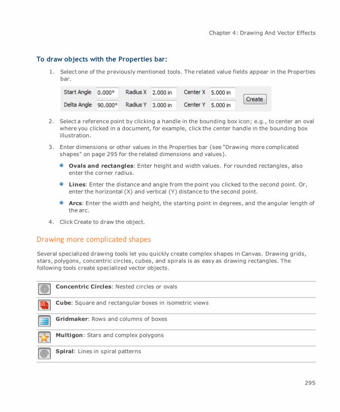
Chapter 4: Drawing And Vector Effects
To draw objects with the Properties bar:
1. Select one of the previously mentioned tools. The related value fields appear in the Propertiesbar.
2. Select a reference point by clicking a handle in the bounding box icon; e.g., to center an ovalwhere you clicked in a document, for example, click the center handle in the bounding boxillustration.
3. Enter dimensions or other values in the Properties bar (see "Drawing more complicatedshapes" on page 295 for the related dimensions and values).
Ovals and rectangles: Enter height and width values. For rounded rectangles, alsoenter the corner radius.
Lines: Enter the distance and angle from the point you clicked to the second point. Or,enter the horizontal (X) and vertical (Y) distance to the second point.
Arcs: Enter the width and height, the starting point in degrees, and the angular length ofthe arc.
4. Click Create to draw the object.
Drawing more complicated shapes
Several specialized drawing tools let you quickly create complex shapes in Canvas. Drawing grids,stars, polygons, concentric circles, cubes, and spirals is as easy as drawing rectangles. Thefollowing tools create specialized vector objects.
Concentric Circles: Nested circles or ovals
Cube: Square and rectangular boxes in isometric views
Gridmaker: Rows and columns of boxes
Multigon: Stars and complex polygons
Spiral: Lines in spiral patterns
295

Canvas 12 User Guide
Registration Marks: Registration marks around a graphic for which you intend to printseparations
EasyShapes: All kinds of shapes, including arrows, flow chart boxes, dialog balloons,symbols, and banners
Calendar: Calendars
Smart Lines: Connect objects with smart lines.
In most cases, you can treat these vector objects like all others. You can move them and resize theirbounding boxes. They can be rotated, flipped, and scaled. You can apply strokes, pen inks and fillinks to them. However, most of these objects are compound objects, which means that they are madeup of separate objects. Therefore, some inks and other effects appear differently when applied tothese objects than to simple vector objects like rectangles and ovals.
Some of the specialized objects have unique editing features. For example, you can twirl the points ofa star, star outline, or framed star by dragging special handles. You can also specify the number ofpoints of a star, the number of rows and columns in a grid, the number of rings in concentric circles,and the number of revolutions in a spiral. You can draw a cube with or without a perspective effect.Methods for drawing and modifying all of the specialized objects appear with the individual tooldescriptions that follow.
You can also convert most specialized vector objects to paths, which lets you edit the object anchorpoints and segments (see "Converting objects and text to paths" on page 343).
Drawing concentric circles
The Concentric Circles tool draws nested rings of ovals or circles. You can set the number andspacing of the rings before or after you draw concentric circles.
To use the Concentric Circles tool:
1. Select the Concentric Circles tool.
2. Drag to draw a bounding box that defines the size of the concentric circles object. Arectangular bounding box creates concentric ovals; a square bounding box creates truecircles.
3. When you finish, the concentric circles object is selected.
296
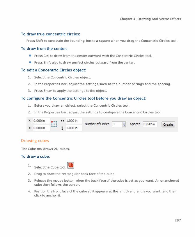
Chapter 4: Drawing And Vector Effects
To draw true concentric circles:
Press Shift to constrain the bounding box to a square when you drag the Concentric Circles tool.
To draw from the center:
Press Ctrl to draw from the center outward with the Concentric Circles tool.
Press Shift also to draw perfect circles outward from the center.
To edit a Concentric Circles object:
1. Select the Concentric Circles object.
2. In the Properties bar, adjust the settings such as the number of rings and the spacing.
3. Press Enter to apply the settings to the object.
To configure the Concentric Circles tool before you draw an object:
1. Before you draw an object, select the Concentric Circles tool.
2. In the Properties bar, adjust the settings to configure the Concentric Circles tool.
Drawing cubes
The Cube tool draws 2D cubes.
To draw a cube:
1. Select the Cube tool.
2. Drag to draw the rectangular back face of the cube.
3. Release themouse button when the back face of the cube is set as you want. An unanchoredcube then follows the cursor.
4. Position the front face of the cube so it appears at the length and angle you want, and thenclick to anchor it.
297
Canvas 12 User Guide
To constrain the faces of the cube to perfect squares, hold down the Shift key while drawingthe back face.
To give the cube a perspective effect by enlarging the front face:
Hold down the Alt key before you anchor the cube.
To edit cubes:
Do one or more of the following:
To change the height or width of a cube, click the cube to select it, and then drag acorner handle.
To reshape a cube by moving a side, double-click the cube to place it in edit mode. Ablack circular handle appears on each of the six faces of the cube.
When you point to a handle, the outline flashes on the corresponding side of the cube.You can drag the handle tomove that side. Click outside the cube to leave edit mode.
Drawing spirals
The Spiral tool draws a smooth, spiraling curve. You can set the number of spiral turns before orafter you draw a Spiral object.
To use the Spiral tool:
1. Select the Spiral tool.
2. Drag diagonally to specify the size of the spiral curve.
To create a circular spiral:
Press Shift and drag.
To configure the Spiral tool:
1. Select the Spiral tool.
2. In the Properties bar, set the number of spirals and the spiral direction.
298
Chapter 4: Drawing And Vector Effects
To change the number of spirals in an object:
1. Select the Spiral object.
2. In the Properties bar, change the number of spirals and press Enter.
Drawing grids
The Gridmaker tool draws grids of rows and columns. Set the number of rows and columns before orafter you draw a grid object.
To use the Gridmaker tool:
1. Select the Gridmaker tool.
2. Drag diagonally to define the grid’s bounding box.
To create a square grid:
Press Shift and drag.
To configure the Gridmaker tool:
1. Select the Gridmaker tool.
2. In the Properties bar, set the number of boxes comprising the grid as well as the cell size.
If you set Boxes Across to 1, the grid has no vertical lines. If you set Boxes Down to 1, thegrid has no horizontal lines.
To modify grid object:
1. Select the Grid object.
2. In the Properties bar, change the number of boxes or cell size and press Enter.
To separate a grid into lines:
Adjust the individual lines that comprise a grid by converting it to a path and then ungrouping it.
1. Select the Grid object.
2. Choose Path | Convert to Paths.
3. ChooseObject | Ungroup. The grid object separates into individual lines.
299

Canvas 12 User Guide
Drawing multigon shapes
Use the Multigon tool to draw all types of multi-sided objects, including triangles, hexagons,pentagons, octagons, stars, circular starbursts, and similar shapes. To set the number of sides andthe style of a multigon, configure the Multigon tool before you draw.
To draw with the Multigon tool:
1. Select the Multigon tool.
2. Drag diagonally to define themultigon’s bounding box.
To make the bounding box square:
Press Shift and drag.
To configure the Multigon tool:
1. Select the Multigon tool.
2. In the Properties bar, set the multigon options.
3. Press Enter.
Multigon options
The available options depend on the selected multigon style.
Style Select the style of the multigon:
Frame: No interior lines.Framed Star: Combination of Frame and Star objects.Spoke: No sides connecting the spoke points.Star: Points connected by interior lines.Star Outline: Multiple points with no interior lines.Wheel: Combination of Frame and Spoke objects.
Points For stars, framed stars, and star outlines, enter the number of starpoints from 3 to 100. For other styles, enter the number of sides from 3to 100.
Smooth Turn this option on to smooth the object’s angles.
Inset Ratio Drag the slider to change the interior area of stars, framed stars, andstar outlines.
300
Chapter 4: Drawing And Vector Effects
Pinwheel angle For stars, enter a value of more or less than 0 degrees to bend thepoints. Negative values bend the points counterclockwise.
Presets Choose a preset style in the pop-up menu.
To save Multigon presets:
1. Select the Multigon shape you want to save as a preset.
2. In the Properties bar, click the Presets menu, and select Save shape.
3. In the Save Shape dialog box, enter a name for the shape, then click OK.
To delete Multigon presets:
1. Select the Multigon tool.
2. In the Properties bar, click the Presets menu, and select Delete shape.
3. In the Delete Shape dialog box, select the preset you want to delete, then click OK.
When you save and delete styles, they remain saved or deleted whether you click OK orCancel to close the Multigon dialog box.
To edit Star Multigon objects:
You can edit Star Multigons (framed star, star, and star outline styles) to adjust the twirl and radiusof the object’s points. The following procedures do not apply to frames, spokes, or wheels.
1. Double-click the Star Multigon object to put it in edit mode.
An outer handle and inner handle appear on one point of the star.
2. Do one or more of the following:
To change the length of the star points: Drag the outer handle inward or outwardfrom the center of the star.
To twirl the points: Drag the handle clockwise or counterclockwise.
To change the position of the inner points: Drag the inner handle inward oroutward from the center.
3. Press Esc or double-click outside the object to exit edit mode.
301
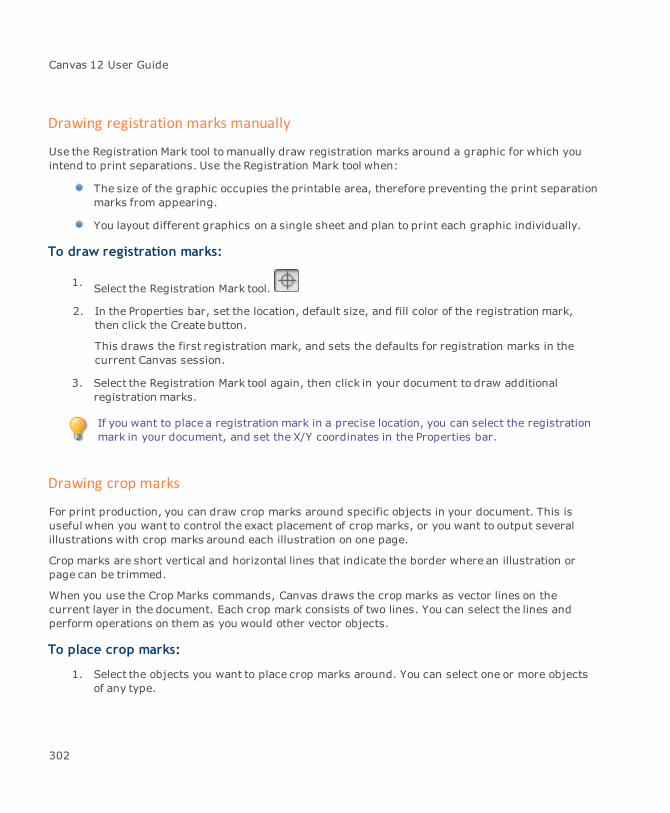
Canvas 12 User Guide
Drawing registration marks manually
Use the Registration Mark tool to manually draw registration marks around a graphic for which youintend to print separations. Use the Registration Mark tool when:
The size of the graphic occupies the printable area, therefore preventing the print separationmarks from appearing.
You layout different graphics on a single sheet and plan to print each graphic individually.
To draw registration marks:
1. Select the Registration Mark tool.
2. In the Properties bar, set the location, default size, and fill color of the registration mark,then click the Create button.
This draws the first registration mark, and sets the defaults for registration marks in thecurrent Canvas session.
3. Select the Registration Mark tool again, then click in your document to draw additionalregistration marks.
If you want to place a registration mark in a precise location, you can select the registrationmark in your document, and set the X/Y coordinates in the Properties bar.
Drawing crop marks
For print production, you can draw crop marks around specific objects in your document. This isuseful when you want to control the exact placement of crop marks, or you want to output severalillustrations with crop marks around each illustration on one page.
Crop marks are short vertical and horizontal lines that indicate the border where an illustration orpage can be trimmed.
When you use the Crop Marks commands, Canvas draws the crop marks as vector lines on thecurrent layer in the document. Each crop mark consists of two lines. You can select the lines andperform operations on them as you would other vector objects.
To place crop marks:
1. Select the objects you want to place crop marks around. You can select one or more objectsof any type.
302

Chapter 4: Drawing And Vector Effects
2. ChooseObject | Options | Crop Marks.
3. In the Crop Marks dialog box, in the Outset box, enter the distance you want the cropboundary to be from the selection.
If one object is selected, the selection boundary is the object’s bounding box.
If more than one object is selected, the selection boundary is the smallest rectangle thatwould enclose all the selected objects.
4. Select the Use Registration Ink option to assign Registration ink color to the crop marks.
Registration ink appears black, but it prints on all plates when you output color separations.This option should be selected if you want the crop marks to print on all plates.
5. Click OK to create the crop marks.
Drawing calendars
To use the Calendar tool:
1. Define at least a 1-inch x 1-inch rectangle.
2. Select the Calendar tool and the cursor changes to a crosshair.
3. Drag the crosshair to form at least a 1-inch x 1-inch rectangle and the Calendar dialog boxopens so you can define your calendar.
To create a calendar:
1. Enter the starting month and year. The default month is the current month and year.
2. Enter the ending month and year. The default month is the current month and year.
3. Enter the number of columns; e.g., if your calendar is for 8 months and you enter 4 in thisfield, your calendar would have 4 columns and 2 rows.
Select the Include Lunar Phases check box if you want lunar phases to appear on yourcalendar.
Drawing EasyShapes
You can use EasyShapes to quickly add all kinds of shapes, including arrows, flowchart symbols,dialog balloons, symbols, and banners.
303
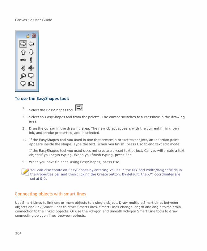
Canvas 12 User Guide
To use the EasyShapes tool:
1. Select the EasyShapes tool.
2. Select an EasyShapes tool from the palette. The cursor switches to a crosshair in the drawingarea.
3. Drag the cursor in the drawing area. The new object appears with the current fill ink, penink, and stroke properties, and is selected.
4. If the EasyShapes tool you used is one that creates a preset text object, an insertion pointappears inside the shape. Type the text. When you finish, press Esc to end text edit mode.
If the EasyShapes tool you used does not create a preset text object, Canvas will create a textobject if you begin typing. When you finish typing, press Esc.
5. When you have finished using EasyShapes, press Esc.
You can also create an EasyShapes by entering values in the X/Y and width/height fields inthe Properties bar and then clicking the Create button. By default, the X/Y coordinates areset at 0,0.
Connecting objects with smart lines
Use Smart Lines to link one or more objects to a single object. Draw multiple Smart Lines betweenobjects and link Smart Lines to other Smart Lines. Smart Lines change length and angle tomaintainconnection to the linked objects. Or use the Polygon and Smooth Polygon Smart Line tools to drawconnecting polygon lines between objects.
304
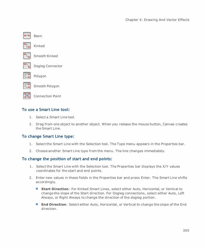
Chapter 4: Drawing And Vector Effects
Basic
Kinked
Smooth Kinked
Dogleg Connector
Polygon
Smooth Polygon
Connection Point
To use a Smart Line tool:
1. Select a Smart Line tool.
2. Drag from one object to another object. When you release the mouse button, Canvas createsthe Smart Line.
To change Smart Line type:
1. Select the Smart Line with the Selection tool. The Type menu appears in the Properties bar.
2. Choose another Smart Line type from the menu. The line changes immediately.
To change the position of start and end points:
1. Select the Smart Line with the Selection tool. The Properties bar displays the X/Y valuescoordinates for the start and end points.
2. Enter new values in these fields in the Properties bar and press Enter. The Smart Line shiftsaccordingly.
Start Direction: For Kinked Smart Lines, select either Auto, Horizontal, or Vertical tochange the slope of the Start direction. For Dogleg connections, select either Auto, LeftAlways, or Right Always to change the direction of the dogleg portion.
End Direction: Select either Auto, Horizontal, or Vertical to change the slope of the Enddirection.
305
Canvas 12 User Guide
Tab Length: This value refers to the horizontal portion of a dogleg connection createdwith the Dogleg Connector tool. Enter a value in this field and press Enter. The angledportion of the connection does not change.
If the Dogleg Connector or a Kinked or Smooth Kinked Smart Line is selected, the Propertiesbar contains additional information, which is not applicable to Basic Smart Lines.
To unsmooth a Smooth Kinked Smart Line:
Select the line and choose Kinked from the Type menu in the Properties bar.
To smooth a Kinked Smart Line:
Select the Kinked Smart Line and choose Smooth Kinked from the Type menu.
To use the Connection Point tool:
This tool is used tomove the anchor points of a vector object. You can also add and remove anchorpoints.
1. Select the Connection Point tool. The cursor changes to a crosshair.
2. Click on an existing vector object. The anchor points appear. When you place the crosshairon an anchor point, the anchor point is emphasized.
3. Click the crosshair on an anchor point and drag it to its new location. You cannot move ananchor point beyond an object’s bounding box.
To add an anchor point: Ctrl-click the crosshair anywhere within the vector object.
To remove an anchor point: Press Control+Shift and click the crosshair on the existinganchor point that you want to delete.
To use the Polygon or Smooth Polygon Smart Line tool:
These tools are used to draw polygon lines between objects.
1. Select the Polygon or Smooth Polygon Smart Line tool. The cursor changes to a crosshair.
2. Click on an existing vector object. The anchor points appear.
3. Click the crosshair on an anchor point.
4. Click on a second object and click the crosshair on an anchor point.
5. Press Esc to exit edit mode.
306
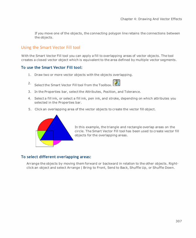
Chapter 4: Drawing And Vector Effects
If you move one of the objects, the connecting polygon line retains the connections betweenthe objects.
Using the Smart Vector Fill tool
With the Smart Vector Fill tool you can apply a fill to overlapping areas of vector objects. The toolcreates a closed vector object which is equivalent to the area defined by multiple vector segments.
To use the Smart Vector Fill tool:
1. Draw two or more vector objects with the objects overlapping.
2. Select the Smart Vector Fill tool from the Toolbox.
3. In the Properties bar, select the Attributes, Position, and Tolerance.
4. Select a fill ink, or select a fill ink, pen ink, and stroke, depending on which attributes youselected in the Properties bar.
5. Click an overlapping area of the vector objects to create the vector fill object.
In this example, the triangle and rectangle overlap areas on thecircle. The Smart Vector Fill tool has been used to create vector fillobjects for the overlapping areas.
To select different overlapping areas:
Arrange the objects by moving them forward or backward in relation to the other objects. Right-click an object and select Arrange | Bring to Front, Send to Back, Shuffle Up, or Shuffle Down.
307

Canvas 12 User Guide
Smart Vector Fill properties
Attributes Default Fill Ink: Creates a vector object using the fill ink selected in theToolbox.
Default Fill and Pen Ink, and Stroke: Creates a vector object usingthe fill ink, pen ink, and stroke selected in the Toolbox.
If you want to use the Fill, Pen Ink, and Stroke option, you mightwant to set these attributes before you create your overlappingobjects and use the Smart Vector Fill tool.To set the attributes, create an object with these attributes first,and then click the Set Default Attributes button tomake thoseattributes the default. The Smart Vector Fill tool uses thesedefault attributes to create the fill in the overlapping areas youselect.
Position Behind vector paths: Creates a vector object behind the other vectorsegment objects.Above vector paths: Creates a vector object in front of the other vectorsegment objects.
Tolerance Select a level of tolerance. This value sets the threshold for how close vectorsegments need to be before an area is considered enclosed.
Exact: Offers the lowest level of tolerance.Fine: Offers a low level of tolerance.Loose: Offers the highest level of tolerance.
Adding annotations
You can use the annotations tools to add labels, callouts, or comments to your diagrams orillustrations, or to create simple flowcharts. The annotation tools can be found in the Toolbox with theMarkup tools.
Basic: Adds a single annotation and points to a single object.
Multiple Sources: Adds a single annotation and points to one or more objects.
Multiple Notes: Adds multiple annotations and points to a single object.
308

Chapter 4: Drawing And Vector Effects
Flowchart: Creates a simple flowchart.
When you draw in the Layout area with these tools, Canvas creates an object shape and connectorlines. You can change the shape of the object or the type of connector line in the Properties bar. Youcan also edit the label (before you place the annotation), and modify the font and style of the text.
You can alsomodify the outline and fill of the flowchart shapes and connectors using the Pen and Fillinks in the Toolbox.
Before you add annotations to your illustration, consider whether you want to print theannotations. If you do not want to print them, you might consider creating a new layer forthe annotations, which you could hide when you print the illustration.
To add a basic annotation:
1. Select the Basic annotation tool.
2. In the Layout area, click on the object you want the annotation to point to.
3. Move the cursor to place the annotation and click to release the tool.
4. Double-click the annotation text to edit it.
To add an annotation with multiple sources:
1. Select the Multiple Sources annotation tool.
2. In the Layout area, click where you want to place the annotation.
3. Move the cursor to the first object you want the annotation to point to, then click.
4. Move the cursor to another object you want the annotation to point to, then click.
5. When you have finished pointing to objects, press Esc or double-click to release the tool.
6. Double-click the annotation text to edit it.
To add multiple annotations to a single source:
1. Select the Multiple Notes annotation tool.
2. In the Layout area, click on the object you want the annotations to point to.
3. Move the cursor to place the first annotation, then click.
309

Canvas 12 User Guide
4. Move the cursor to place another annotation, then click.
5. When you have finished adding annotations, press Esc or double-click to release the tool.
6. Double-click the annotation text to edit it.
To create a simple flowchart:
1. Select the Flowchart annotation tool.
2. In the Properties bar, click the Shape icon to open the Shape popup palette, then select aflowchart shape to start the flowchart.
3. In the Layout area, click to place the first flowchart shape.
4. In the Properties bar, click the Shape icon to select the next flowchart shape to add to theflowchart.
5. In the Layout area, click to place the second flowchart shape.
6. When you have finished adding flowchart shapes, press Esc or double-click to release thetool.
7. Double-click the annotation text to edit it.
For more complex flowcharts, use the Flowchart palette. See "Creating flowcharts" on page311.
To change the shape of the annotation object:
1. Select the annotation object.
2. In the Properties bar, click the Type icon to open the Shape popup palette.
3. Select another object shape. The object shape changes immediately.
To edit the text in an annotation:
Do one of the following:
If you have not placed the annotation, enter the text in the Text field in the Propertiesbar.
If you have already placed your annotations, select the Text tool and click on the text inthe object to enter text edit mode.
310
Chapter 4: Drawing And Vector Effects
Creating flowcharts
In Canvas, you can use the Flowchart palette to create a flowchart using standard flowchart symbolsand lines. You can adjust the pen, fill, dash, and arrow attributes of the lines, the amount of offsetspacing between symbols, the size of the symbols, and the position of symbols relative to each other.
To create a flowchart:
1. ChooseWindow | Palettes | Flowchart.
2. Drag a flowchart symbol into your document.
3. Add additional symbols, by doing one or more of the following:
Select a symbol in the Flowchart palette, and then click one of the red arrow directionbuttons in the CreateControls section.
Select a symbol in the Flowchart palette, and then click one of the blue arrow directionbuttons in the Branch Controls section.
To set the default attributes of flowchart lines:
In the Flowchart palette, set the Smart Line Attributes to control the pen, fill, dash, and arrowattributes.
To set the default attributes of flowchart symbols:
1. Make sure that no objects are selected in the document.
2. Set the pen, fill, dash, and arrow attributes in the Toolbox.
To change the attributes of flowchart lines or symbols:
1. Select the flowchart lines or symbols in the document.
2. Set the pen, fill, dash, and arrow attributes in the Toolbox.
As with any Canvas object, you can also change the size of the selected symbols, theopacity, and effects such as bevel and shadow. You can also align symbols, rotatethem, or skew them.
311
Canvas 12 User Guide
To replace one symbol with another:
1. Select the symbol you want to replace in your document.
2. Select the replacement symbol in the Flowchart palette.
3. Click the Replace button.
To add text to symbols and lines:
1. In the document, select the symbol or line that you want to add text to.
2. Select the Selection tool from the Toolbox.
3. Type the text you want to add.
You can edit the text, change the font, size, color and other attributes as you would for anytext you enter in Canvas.
Flowchart Symbol properties
Before you place a symbol from the Flowchart palette, be sure to review the symbol properties in theProperties bar.
X and Y Displays the X and Y coordinates where the symbol will be placed bydefault.
Reference point Displays the reference point for the symbol. This is the point on theselected object (or its bounding box) that position data is based on.Thereference point is also the fixed point used in an object’s transformation.
Width and Height Displays the height and width of the object.
Preserve originalproportions
Uses the symbol's original proportions.
Use original colors Uses the symbol's original colors. If you do not select this check box, thesymbol uses the default attributes from the Toolbox.
Create Click Create to place the selected symbol in the document.
312
Chapter 4: Drawing And Vector Effects
Flowchart options
Symbols Click and drag symbols into your document. You must place at least onesymbol in your document before you can use the Create and Branchbuttons.
Create Select a symbol in your document, and then select a symbol in thepalette and use the following buttons:
Add Top: Places the symbol above the symbol selected in thedocument.Add Bottom: Places the symbol below the symbol selected in thedocument.Add Left: Places the symbol to the left of the symbol selected in thedocument.Add Right: Places the symbol to the right of the symbol selected inthe document.
Branch Select a symbol in your document, and then select a symbol in thepalette and use the following buttons to branch the chart:
Branch Top: Places two symbols above the symbol selected in thedocument.Branch Bottom: Places two symbols below the symbol selected inthe document.Branch Left: Places two symbols left of the symbol selected in thedocument.Branch Right: Places two symbols right of the symbol selected inthe document.
Symbol Size Enter the width and height of the symbols. Select the Preserve originalproportions check box to retain the proportions of symbols when youresize them.
Symbol Offset Enter the amount of offset spacing between symbols:
Offset: Defines the distance between one symbol and the nextwhen you place symbols using the Create buttons.Branch Offset: Defines the distance between two symbols placedusing the Branch buttons.
Smart Line Attributes Select the following attributes to apply to the flowchart lines:
PenFill
313
Canvas 12 User Guide
DashArrow
Loading additional symbols
Canvas comes with a set of standard flowchart symbols, but if you have additional symbols you wantto use, you can load them into the Flowchart palette. Any new symbols you add must be in the Canvassymbol file format (.CSY).
To load an additional set of symbols:
1. Save the symbols you want to use in Canvas symbol format (.CSY) and note the location ofthe folder where you have saved them.
The name of this folder is used as the name of the flowchart symbol set in Canvas.
2. Open the Flowchart palette. Choose Window | Palettes | Flowchart.
3. Choose Load Flowchart Symbols from the Flowchart palette menu.
4. In the Browse For Folder dialog box, select the folder where the symbols are located, andclick OK.
The new set of symbols are available from the drop-down list.
To delete a symbol, use a program such as Windows Explorer to delete the symbol, and thenreload the set of symbols in the Flowchart palette to refresh the palette.
Using Math Expression 2-D Plot commands
In Canvas you can use Math Expressions to create a visual representation of an equation. The visualrepresentation is created as a vector object that uses the current Pen and Fill inks. You can also applyany vector object effect as well as change the Pen and Fill inks. These objects can also be renderedand exported as images.
To open the Math expression 2-D Cartesian Plot dialog box:
Choose Path | Math Expression 2-D Plot | Cartesian.
To open the Math expression 2-D Polar Plot dialog box:
Choose Path | Math Expression 2-D Plot | Polar.
314
Chapter 4: Drawing And Vector Effects
To use the Math Expression 2-D Plot commands:
1. Define the mathematical equation using the Categories and Items scroll boxes.
2. Double-click an item to add it to the Expression field.
The lower portion of the dialog box indicates the correct syntax and shows an exampleof the expression.
3. Enter values in the range fields. The maximum rangemust be greater than the minimumrange. You can also enter a value in the “1 Unit of” fields to set a scale.
4. Use the Steps menu to control the quality of the curve.
5. Click OK to create the visual representation.
To save an expression:
1. Click on themenu icon and select Save expression as.
2. In the Save expression as dialog box, enter a name for the expression and click OK.
Saved expressions appear at the bottom of the menu list.
To load a saved expression:
Click on themenu icon and select the expression’s name from the list. The equation appears in theExpression field.
To delete a saved expression:
1. Click on themenu icon and select Delete expression.
2. In the Delete expression preset dialog box, select the expression you want to delete, andclick OK.
Examples
The following visual representations were created using the Math Expression 2-D Polar Plot dialogbox.
315

Canvas 12 User Guide
Formula: r=1-sin(q)Expression: r=1-sin(x)x: 0 - 6.29r: -10 - 10Counterclockwise1/1
Formula: r=sin(2q)Expression: r=sin(x)x: 0 - 6.29r: -10 - 10Counterclockwise1/1
Formula: r=2qExpression: r=2*xx: -31.4 - 31.4r: -50 - 50Counterclockwise1/40
Formula: r=sin(6q)+log(1.5)Expression: r=sin(6*x)+log(1.5)x: 0 - 6.29r: -10 - 10Counterclockwise1/1
Formula: r=qsin2(q)Expression: r=x*(sin(x))^2x: 0 - 6.29r: -10 - 10Counterclockwise1/3
Drawing & editing paths
Path tools let you draw and edit vector object paths of any shape. This section explains how to drawpaths, edit paths, and edit curves segments using the control points that define them.
316

Chapter 4: Drawing And Vector Effects
Drawing with the Path tools
You can use the Curve, Polygon, Smooth Polygon, Freehand, and Auto Curve tools to draw vectorobjects as open or closed paths. When you use the Curve, Polygon, Smooth Polygon, and Auto Curvetools, you set anchor points to define path segments. With the Freehand tool, you simply drag todraw a path. The Reshape and Push tools let you edit paths.
Curve Push
Polygon Reshape
Smooth Polygon Auto Curve
Freehand
The Polygon tool draws paths with straight segments. The Smooth Polygon tool draws paths withsmooth line segments. The Curve and Auto Curve tools can draw paths with straight and curvedsegments. Paths drawn with the Freehand tool generally aremade of curved segments based on themovement of the pointer.
When you draw with the Path tools, Canvas uses the current pen ink, fill ink, and stroke settings forthe vector objects you create.
Drawing polygons
When you use the Polygon or Smooth Polygon tool to draw an object, you set anchor points that definea path of straight line segments or smooth line segments, respectively. You can later curve thestraight segments, as with any path object. For editing information, see "Editing object paths" onpage 324.
To draw polygons:
1. Select the Polygon tool or Smooth Polygon tool.
2. Click to set the first anchor point, shown as a small square.
3. Click where you want to place the second anchor point.
You can press the pointer to display the segment, drag to position it, and then release themouse button.
317
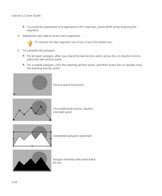
Canvas 12 User Guide
To constrain placement of a segment to 45° intervals, press Shift while drawing thesegment.
4. Repeat the last step to draw more segments.
To remove the last segment you drew, press the Delete key.
5. To complete the polygon:
For an open polygon, after you place the last anchor point, press Esc or double-click toplace the last anchor point.
For a closed polygon, click the starting anchor point, and then press Esc or double-clickthe starting anchor point.
Click to place first point
Click additional points, double-click last point
Completed polygon (selected)
Polygon finished with solid blackfill ink
318
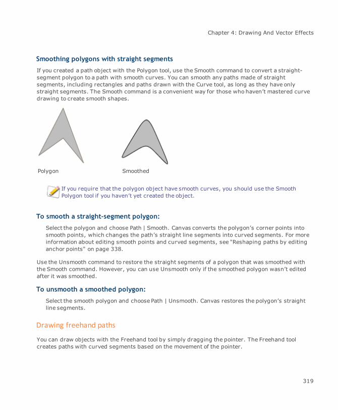
Chapter 4: Drawing And Vector Effects
Smoothing polygons with straight segments
If you created a path object with the Polygon tool, use the Smooth command to convert a straight-segment polygon to a path with smooth curves. You can smooth any paths made of straightsegments, including rectangles and paths drawn with the Curve tool, as long as they have onlystraight segments. The Smooth command is a convenient way for those who haven’t mastered curvedrawing to create smooth shapes.
Polygon Smoothed
If you require that the polygon object have smooth curves, you should use the SmoothPolygon tool if you haven’t yet created the object.
To smooth a straight-segment polygon:
Select the polygon and choose Path | Smooth. Canvas converts the polygon’s corner points intosmooth points, which changes the path’s straight line segments into curved segments. For moreinformation about editing smooth points and curved segments, see "Reshaping paths by editinganchor points" on page 338.
Use the Unsmooth command to restore the straight segments of a polygon that was smoothed withthe Smooth command. However, you can use Unsmooth only if the smoothed polygon wasn’t editedafter it was smoothed.
To unsmooth a smoothed polygon:
Select the smooth polygon and choose Path | Unsmooth. Canvas restores the polygon’s straightline segments.
Drawing freehand paths
You can draw objects with the Freehand tool by simply dragging the pointer. The Freehand toolcreates paths with curved segments based on the movement of the pointer.
319
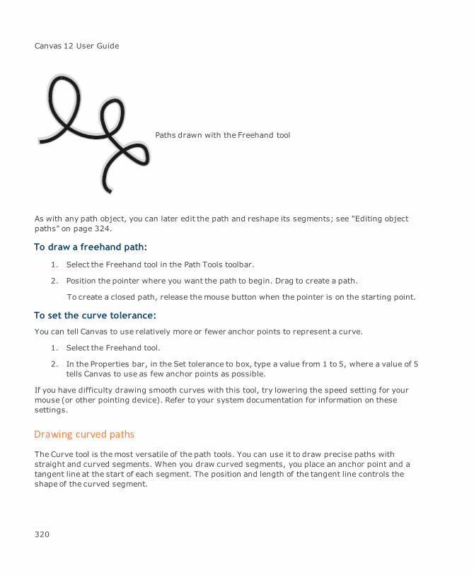
Canvas 12 User Guide
Paths drawn with the Freehand tool
As with any path object, you can later edit the path and reshape its segments; see "Editing objectpaths" on page 324.
To draw a freehand path:
1. Select the Freehand tool in the Path Tools toolbar.
2. Position the pointer where you want the path to begin. Drag to create a path.
To create a closed path, release themouse button when the pointer is on the starting point.
To set the curve tolerance:
You can tell Canvas to use relatively more or fewer anchor points to represent a curve.
1. Select the Freehand tool.
2. In the Properties bar, in the Set tolerance to box, type a value from 1 to 5, where a value of 5tells Canvas to use as few anchor points as possible.
If you have difficulty drawing smooth curves with this tool, try lowering the speed setting for yourmouse (or other pointing device). Refer to your system documentation for information on thesesettings.
Drawing curved paths
The Curve tool is themost versatile of the path tools. You can use it to draw precise paths withstraight and curved segments. When you draw curved segments, you place an anchor point and atangent line at the start of each segment. The position and length of the tangent line controls theshape of the curved segment.
320
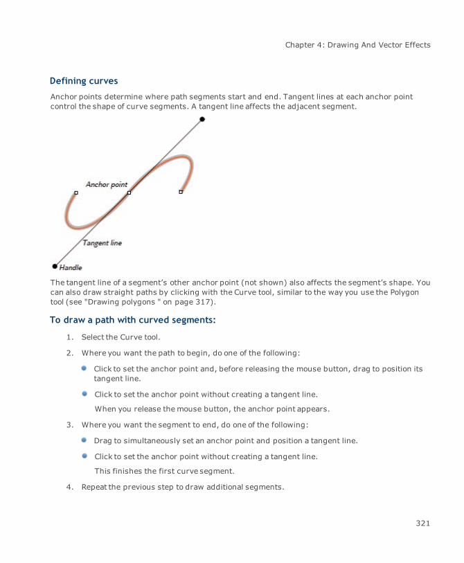
Chapter 4: Drawing And Vector Effects
Defining curves
Anchor points determine where path segments start and end. Tangent lines at each anchor pointcontrol the shape of curve segments. A tangent line affects the adjacent segment.
The tangent line of a segment’s other anchor point (not shown) also affects the segment’s shape. Youcan also draw straight paths by clicking with the Curve tool, similar to the way you use the Polygontool (see "Drawing polygons " on page 317).
To draw a path with curved segments:
1. Select the Curve tool.
2. Where you want the path to begin, do one of the following:
Click to set the anchor point and, before releasing the mouse button, drag to position itstangent line.
Click to set the anchor point without creating a tangent line.
When you release themouse button, the anchor point appears.
3. Where you want the segment to end, do one of the following:
Drag to simultaneously set an anchor point and position a tangent line.
Click to set the anchor point without creating a tangent line.
This finishes the first curve segment.
4. Repeat the previous step to draw additional segments.
321

Canvas 12 User Guide
5. To complete the path, use one of the following options:
For an open path, after you place the last anchor point, press Esc. You can also double-click to place the last anchor point.
For a closed path, click the starting anchor point, and then press Esc. You can alsodouble-click the starting anchor point.
Shaping and editing segments as you draw
As you draw with the Curve tool, you can usemodifier keys to constrain and edit the path segments.
To place an anchor point at a 45° interval relative to the previous one:
Press Shift as you set the second anchor point.
To create a straight segment:
Press Ctrl as you click to set the segment’s endpoint.
To remove the last segment:
Press the Delete key. You can continue to remove segments in the reverse order you createdthem, until you delete the entire object.
To constrain a tangent line to 45° increments:
Press Shift as you drag the tangent line.
Drawing auto curves
The Auto Curve tool draws and edits curved paths. This tool makes it easy to draw smooth curvesbecause it automatically curves path segments as you simply click or drag the mouse.
When you use the Auto Curve tool, you don’t have to position tangent lines that control the shape ofcurves. Instead, you simply click to set anchor points and smooth curve segments appear. You candrag the mouse to see how the path will curve before you set each anchor point.
Like the other path tools, you can use the Auto Curve tool to draw new paths and to add segments topaths as you edit them.
322

Chapter 4: Drawing And Vector Effects
To use the Auto Curve tool:
1. Select the Auto Curve tool.
2. Click in the drawing area to set the beginning point of a path. If you are editing a path, clickto set the path’s next anchor point.
3. Move the mouse and click to set the second anchor point. A straight segment connects thefirst and second points. You can press Shift when you click to snap the first segment to a45° angle.
4. To set the third anchor point, do one of the following:
Click to set the anchor point. This completes a smooth curve from the first anchor point tothe new anchor point.
Hold down themouse button and move the mouse to preview the curve. You can see thesegments bend as you move the pointer. Release themouse to set the new anchor point.
5. Repeat the previous step to continue adding anchor points to the path. You can also selectother path tools (Curve, Polygon, Push, and Reshape) to continue adding segments to thepath.
6. To finish drawing the path, do one of the following:
Press Esc.
Double-click to set the final anchor point. You must double-click on the starting point tocomplete a closed path.
When you finish drawing, the path object is selected. Canvas applies the current pen ink, fill ink, andstroke to the path. You can use path editing tools and techniques to modify the path.
With the Auto Curve tool, click toset anchor points 1 and 2 to starta path.
323
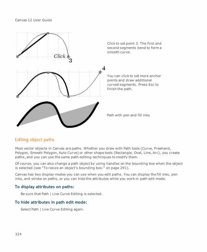
Canvas 12 User Guide
Click to set point 3. The first andsecond segments bend to form asmooth curve.
You can click to set more anchorpoints and draw additionalcurved segments. Press Esc tofinish the path.
Path with pen and fill inks
Editing object paths
Most vector objects in Canvas are paths. Whether you draw with Path tools (Curve, Freehand,Polygon, Smooth Polygon, Auto Curve) or other shape tools (Rectangle, Oval, Line, Arc), you createpaths, and you can use the same path-editing techniques tomodify them.
Of course, you can also change a path object by using handles on the bounding box when the objectis selected (see "To resize an object’s bounding box:" on page 291).
Canvas has two display modes you can use when you edit paths. You can display the fill inks, peninks, and stroke on paths, or you can hide the attributes while you work in path edit mode.
To display attributes on paths:
Be sure that Path | Live Curve Editing is selected.
To hide attributes in path edit mode:
Select Path | Live Curve Editing again.
324
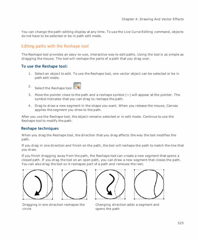
Chapter 4: Drawing And Vector Effects
You can change the path-editing display at any time. To use the Live Curve Editing command, objectsdo not have to be selected or be in path edit mode.
Editing paths with the Reshape tool
The Reshape tool provides an easy-to-use, interactive way to edit paths. Using the tool is as simple asdragging themouse. The tool will reshape the parts of a path that you drag over.
To use the Reshape tool:
1. Select an object to edit. To use the Reshape tool, one vector object can be selected or be inpath edit mode.
2. Select the Reshape tool.
3. Move the pointer close to the path and a reshape symbol (~) will appear at the pointer. Thesymbol indicates that you can drag to reshape the path.
4. Drag to draw a new segment in the shape you want. When you release the mouse, Canvasapplies the segment you drew to the path.
After you use the Reshape tool, the object remains selected or in edit mode. Continue to use theReshape tool to modify the path.
Reshape techniques
When you drag the Reshape tool, the direction that you drag affects the way the tool modifies thepath.
If you drag in one direction and finish on the path, the tool will reshape the path tomatch the line thatyou draw.
If you finish dragging away from the path, the Reshape tool can create a new segment that opens aclosed path. If you drag the tool on an open path, you can draw a new segment that closes the path.You can also drag the tool so it reshapes part of a path and removes the rest.
Dragging in one direction reshapes thecircle
Changing direction adds a segment andopens the path
325
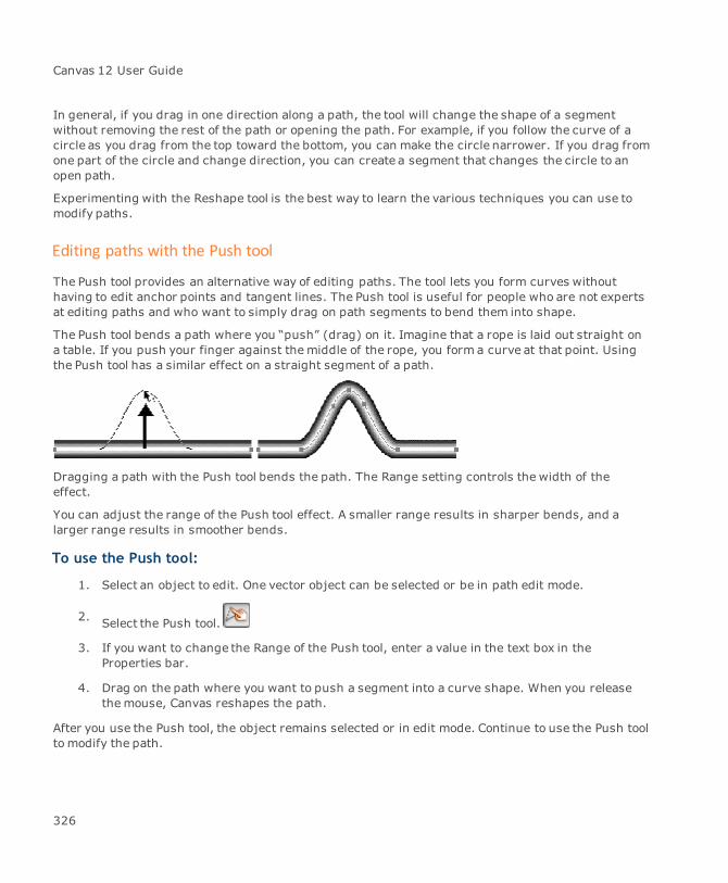
Canvas 12 User Guide
In general, if you drag in one direction along a path, the tool will change the shape of a segmentwithout removing the rest of the path or opening the path. For example, if you follow the curve of acircle as you drag from the top toward the bottom, you can make the circle narrower. If you drag fromone part of the circle and change direction, you can create a segment that changes the circle to anopen path.
Experimenting with the Reshape tool is the best way to learn the various techniques you can use tomodify paths.
Editing paths with the Push tool
The Push tool provides an alternative way of editing paths. The tool lets you form curves withouthaving to edit anchor points and tangent lines. The Push tool is useful for people who are not expertsat editing paths and who want to simply drag on path segments to bend them into shape.
The Push tool bends a path where you “push” (drag) on it. Imagine that a rope is laid out straight ona table. If you push your finger against themiddle of the rope, you form a curve at that point. Usingthe Push tool has a similar effect on a straight segment of a path.
Dragging a path with the Push tool bends the path. The Range setting controls the width of theeffect.
You can adjust the range of the Push tool effect. A smaller range results in sharper bends, and alarger range results in smoother bends.
To use the Push tool:
1. Select an object to edit. One vector object can be selected or be in path edit mode.
2. Select the Push tool.
3. If you want to change the Range of the Push tool, enter a value in the text box in theProperties bar.
4. Drag on the path where you want to push a segment into a curve shape. When you releasethemouse, Canvas reshapes the path.
After you use the Push tool, the object remains selected or in edit mode. Continue to use the Push toolto modify the path.
326
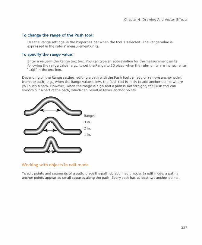
Chapter 4: Drawing And Vector Effects
To change the range of the Push tool:
Use the Range settings in the Properties bar when the tool is selected. The Range value isexpressed in the rulers’ measurement units.
To specify the range value:
Enter a value in the Range text box. You can type an abbreviation for themeasurement unitsfollowing the range value; e.g., to set the Range to 10 picas when the ruler units are inches, enter“10p” in the text box.
Depending on the Range setting, editing a path with the Push tool can add or remove anchor pointfrom the path; e.g., when the Range value is low, the Push tool is likely to add anchor points whereyou push a path. However, when the range is high and a path is not straight, the Push tool cansmooth out a part of the path, which can result in fewer anchor points.
Range:
3 in.
2 in.
1 in.
Working with objects in edit mode
To edit points and segments of a path, place the path object in edit mode. In edit mode, a path’sanchor points appear as small squares along the path. Every path has at least two anchor points.
327

Canvas 12 User Guide
Object path drawn with Curve tool
Object in edit mode, with anchor points visible
When an object is in edit mode, you can select one or more anchor points. You can even select anchorpoints and segments on more than one object at once, as long as the objects are in edit mode.
To place an object in edit mode:
Do one of the following to place a path object in edit mode:
Select the object with the Direct edit selection tool.
Double-click the object with the Selection tool.
Select the object and choose Path | Edit Path or choose Object | Edit | Object.
Select the Selection tool after placing an anchor point while you are drawing a path.
328
Chapter 4: Drawing And Vector Effects
To place multiple objects in edit mode:
Place two or more objects in edit mode by selecting them with the Direct edit lasso selection tool orby selecting them with the Selection tool and then choosing Path | Edit Path.
To return from edit mode:
When you finish editing an object, click outside the object with either the Direct edit selection toolor Direct edit lasso selection tool. You can also double-click outside the object with the Selectiontool. In addition, you can press the Esc key to leave edit mode.
To edit special vector objects:
Some Canvas drawing tools create specialized objects. When you double-click one of theseobjects to place it in edit mode, Canvas displays special editing handles or configuration options,rather than the anchor points and segments of a regular path object.
The tools that create special vector objects are the Concentric Circles, Cube, Polygon, Grid Maker,Multigon, or Spiral. Also, when you modify objects with the Envelope or Extrude commands, Canvascreates specialized objects.
If you want to use path-editing techniques to modify these objects, convert them to paths. Thisusually produces a group of objects. After you ungroup these objects, you have regular paths thatcan be edited using the techniques that follow. You can also convert text characters to paths so thatyou can edit the shapes of individual characters (see "Converting objects and text to paths" on page343).
Editing paths with the context menu
When a path is in edit mode, use the context menu to quickly add, delete, and change anchor pointsand tangent lines. To see this menu, right-click with at least one object in path edit mode. Theavailable options vary depending on the location of the pointer. Each option is described next.
Delete Point: Available when the pointer is on an anchor point and appears as a crosshair.Removes the anchor point from the path, and connects the adjacent anchor points with anew segment.
Cusp: Available when the pointer is on a tangent line handle or an anchor point. On anchorpoints, this option deletes the point’s tangent lines. On tangent line handles, this optionmakes the path either smooth or cornered at the anchor point. To be smooth, the anchorpointmust have both sides of a tangent line. When smooth, the halves of the tangent line arealways 180° from each other and rotate around the anchor point like a propeller. When theanchor point is a corner, the tangent line segments can move independently around theanchor point, like the hands of a clock.
329

Canvas 12 User Guide
Smooth: Available when two or more points of an object are selected. You can smooth anypaths made of straight segments.
Fillet: Available when the pointer is on a corner point (with less than two tangent linesbetween two segments. Fillet creates a radius corner between the two segments. When youchoose Fillet, in the dialog box, enter a radius value in the text box and click OK. The largerthe radius value, the larger the curved segment. A message appears if the radius value is toolarge for the angle of the segments.
Add Point: Available when the pointer is on a path segment and appears as a grayarrowhead. Inserts an anchor point with a tangent line where you click.
Break: Available when the pointer is a gray arrowhead on a path. Splits the path segment atthat location, and adds anchor points to the ends of the resulting segments.
Join: Available when you select two anchor points that are not connected. Connects theselected points with a straight segment.
Delete Handle: Available when the pointer is on a tangent line handle and appears as acrosshair. Removes the handle and the effects of the tangent line on the path (see "To deletetangent lines:" on page 341).
Add Handle: Available when the pointer is on an anchor point and there are fewer than twotangent line segments at the anchor point. Adds one or two tangent line segment to theanchor point (see "To add a tangent line:" on page 341).
Straighten: Available when the pointer is on a path segment and appears as a grayarrowhead. Makes the path segment straight by removing tangent lines from the segment’sanchor points.
Enable Symmetrical Drag: Available when an object is in path edit mode. You can easilycreate a symmetrical design from a circle, rectangle, or a complex group of objects (see "Tosymmetrically resize path points:" on page 347).
Selecting anchor points and segments
When you edit paths, you need to select particular anchor points or segments before you can delete,move, or reshape them. Before you can select anchor points and segments, a path object must be inedit mode (see "To place an object in edit mode:" on page 328).
When a path is in edit mode and you point to an anchor point with a Selection tool, the pointerbecomes a crosshair. When you point to a segment, the pointer becomes a gray arrowhead. TheSelection tools are explained in "Selecting objects with Selection tools" on page 159.
When an anchor point is selected, the Properties bar displays settings for angle and length. You caneven add/delete handles or adjust the point to smooth or cusp.
330

Chapter 4: Drawing And Vector Effects
You can select points in more than one path. When you move any selected point, all points in theselection move the same way. (If all the points in a path are selected and you drag one, the entirepath moves.) This also works for segments belonging to separate paths.
Use the Selection tool to select multiple anchor points.
To select anchor points and segments:
With the path object in edit mode, click an anchor point or segment to select it. To select multiplepoints or segments, use either the Direct edit selection tool or the Selection tool to drag a selectionbox around them or Shift-click each point or segment.
To select all anchor points:
With the path object in edit mode, choose Edit | Select All.
To select parts of separate paths:
Place the paths in edit mode, and Shift-click the point or segments.
To inverse a selection:
Choose Edit | Invert Selection. The other points are selected and the current one is deselected.
When an anchor point is selected, it changes from a solid to hollow square. If the anchor point hastangent lines, they appear when the anchor point is selected. All tangent lines that affect the
331

Canvas 12 User Guide
segments that touch the selected anchor point also appear. When you select a segment, the anchorpoint at each end is selected.
Adding and deleting points and segments
If a segment’s anchor points are too far apart for you to adjust the shape as needed, add more. If youcreate or add more anchor points than you need, delete unnecessary ones.
Keep in mind that themore points on a path, themore complex and system resource-intensive itbecomes. In particular, toomany anchor points can cause printing problems. It’s best to use thefewest possible anchor points placed as far apart as possible to create a path.
To add an anchor point:
With an object in edit mode, right-click a segment to which you want to add an anchor point. Inthe path Context menu, choose Add Point. You can also Ctrl-click a segment to add a point.
To delete an anchor point:
With an object in edit mode, right-click the point you want to delete. In the path Context menuthat appears, choose Delete Point. You can also Ctrl+Shift-click a point to delete it, or select pointsand press the Delete key.
To delete a segment:
Select the anchor points at each end and press the Delete key. Deleting a segment of a closed pathdoes not open the path; the remaining segments are joined and the path remains closed.
To add segments to an open path:
Add segments to the end of an open path using the Curve tool or Polygon tool.
If you create the open path with the Smooth Polygon tool, use the Smooth Polygon tool to addsegments.
1. With the object in edit mode, select the endpoint where you want to add a segment.
2. Select the Curve tool (to add straight or curved segments) or Polygon tool (to add straightsegments).
3. Click to add a straight segment beyond the selected endpoint. With the Curve tool, add acurved segment by clicking the mouse to establish the new anchor point and then draggingto position the tangent line.
332

Chapter 4: Drawing And Vector Effects
4. To add additional segments, repeat the previous step. When you finish, press Esc to leaveedit mode.
To add points to a curve:
Often technical illustrators need to quickly add more editing points to a Bézier curve.
1. Select the object.
2. Choose Path | Add Points.
3. In the Add Points dialog box, enter the number of points that you wish to add to the object.
4. Click OK to accept your choice.
Closing and opening paths
A closed path is one that starts and ends at the same anchor point. An open path has separatestarting and ending points. You can close an open path by letting Canvas create a new segment tojoin the path’s two endpoints. Open a closed path by breaking the path.
To close an open path:
With the path in edit mode and the Curve or Polygon tool selected, click one of the endpoints.Canvas closes the path by connecting the endpoints with a new segment. If the adjacentsegments are curved, the new segment follows the curve.
To break a closed path:
With the object in edit mode, right-click an anchor point or segment to open the path Contextmenu. In themenu, choose Break; Canvas inserts segment end points to open the object at thatlocation.
Using the Scissors tool to open and divide paths
Use the Scissors tool to open a closed path and divide a path into two objects. Splitting a path opensthe path at the point where the scissors clip the path.
333
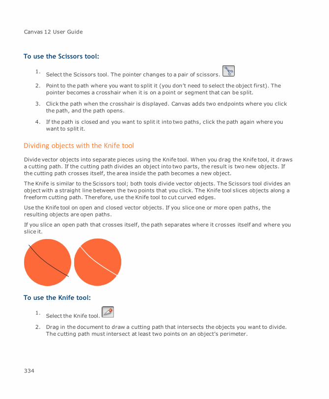
Canvas 12 User Guide
To use the Scissors tool:
1. Select the Scissors tool. The pointer changes to a pair of scissors.
2. Point to the path where you want to split it (you don’t need to select the object first). Thepointer becomes a crosshair when it is on a point or segment that can be split.
3. Click the path when the crosshair is displayed. Canvas adds two endpoints where you clickthe path, and the path opens.
4. If the path is closed and you want to split it into two paths, click the path again where youwant to split it.
Dividing objects with the Knife tool
Divide vector objects into separate pieces using the Knife tool. When you drag the Knife tool, it drawsa cutting path. If the cutting path divides an object into two parts, the result is two new objects. Ifthe cutting path crosses itself, the area inside the path becomes a new object.
The Knife is similar to the Scissors tool; both tools divide vector objects. The Scissors tool divides anobject with a straight line between the two points that you click. The Knife tool slices objects along afreeform cutting path. Therefore, use the Knife tool to cut curved edges.
Use the Knife tool on open and closed vector objects. If you slice one or more open paths, theresulting objects are open paths.
If you slice an open path that crosses itself, the path separates where it crosses itself and where youslice it.
To use the Knife tool:
1. Select the Knife tool.
2. Drag in the document to draw a cutting path that intersects the objects you want to divide.The cutting path must intersect at least two points on an object’s perimeter.
334
Chapter 4: Drawing And Vector Effects
Constraining the path: To constrain the path of the Knife tool to 45° increments, pressShift as you drag. Release the Shift key to drag freely.
Partial cuts: If you stop dragging before the cutting path intersects a second point onan object's perimeter, the cutting path appears but the object stays intact. To use thiscutting path to divide the object, drag a second cutting path so it intersects the perimeterof the object and the first cutting path. Or, you can intersect the cutting path with othercutting paths to create a closed shape. The part of the object that falls within the closedshape becomes a separate object.
Cutting holes: Cut out pieces of a vector object by dragging inside the object andcreating a closed path. The parts of the object that fall within the closed cutting pathbecome separate objects. To create a closed cutting path, the path must cross itself.
Gradient inks: If an object’s fill ink is a gradient, and the style is Radial, Directional,Rectangular, or Elliptical, the gradient remains intact across the separated objects.However, if the gradient style is Shape, the gradient fills each divided object separately.
To configure the Knife tool:
Use the settings in the Properties bar.
Cut Only Selected Objects: Select this option tomake the Knife tool slice only vectorobjects that are selected and intersected by the cutting path. This setting can preventunintentional changes to nearby objects.
Cut All Objects: Select this option to make the Knife tool slice any vector objects thatthe cutting path intersects, whether the objects are selected or not.
Cropping vector and image objects
Canvas contains a Page Crop tool that can be used to crop several objects at once. This tool can beused on both image and vector objects.
If some vector objects contain SpriteEffects, you should render those objects beforeapplying the Page Crop tool.
Any objects that are outside of the cropping rectangle will be deleted after completing the crop. Afterapplying the Page Crop tool, images remain paint objects. Vector objects, however, becomeBéziercurves. The pen stroke, if any, becomes a composite object.
335
Canvas 12 User Guide
You cannot crop text objects or images to which a soft rotate effect has been applied. If youplan on using or editing the original file in the future, ensure that you save a copy of the filebefore applying the Page Crop tool.
To use the Page Crop tool:
1. Select the Page Crop tool. The cursor changes to a crosshair.
2. Drag the crosshair diagonally across the objects to form a cropping rectangle.
3. Move the cropping rectangle, if necessary. Place the cursor on the border of the croppingrectangle and a hand appears.
4. Resize the cropping rectangle, if necessary.
5. Place the cursor within the cropping rectangle and click to complete the crop.
Periodic waveforms
In Canvas, you can easily add a sine wave, sawtooth wave, or square wave to a Bézier or polygonsegment that is in curve edit mode.
This command can be applied to one segment at a time.
To create a waveform:
1. Ensure that the Bézier curve or polygon is in curve edit mode.
2. Right-click on the path segment to access the context menu.
3. Select one of the wave options: Insert SineWave, Insert Square Wave, or Insert SawtoothWave.
4. In theWave Configuration dialog box, enter a value for the frequency in the # Cycles field.
5. Enter a value for the Amplitude.
6. Click OK.
336
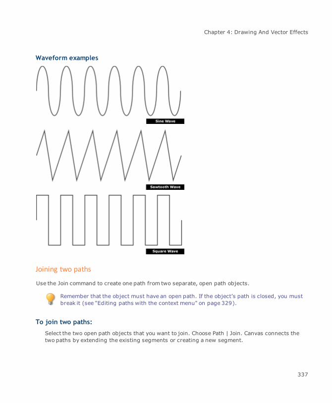
Chapter 4: Drawing And Vector Effects
Waveform examples
Joining two paths
Use the Join command to create one path from two separate, open path objects.
Remember that the object must have an open path. If the object’s path is closed, you mustbreak it (see "Editing paths with the context menu" on page 329).
To join two paths:
Select the two open path objects that you want to join. Choose Path | Join. Canvas connects thetwo paths by extending the existing segments or creating a new segment.
337
Canvas 12 User Guide
To join paths at selected endpoints:
Canvas, by default, joins paths at the closest endpoints; however, you can select which endpoints tojoin.
1. Place an open object or multiple open objects in edit mode.
2. Click an endpoint you want to join to another path. The endpoint becomes hollow to indicatethat it is selected.
You can also draw a selection box around the object’s endpoints with either theSelection tool or Direct edit selection tool.
3. Shift-click another endpoint. The endpoint also becomes hollow to indicate that it is selected.
4. Choose Path | Join or right-click one of the selected points. In the context menu, choose Join.
Moving anchor points and segments
With a path in edit mode, you can move points and segments to alter the shape of the path.
Drag an anchor point or segment tomove it. You can also press the keyboard arrow keys tomoveselected points and segments. Moving reshapes the segments you drag or the segments attached tothe points that you move.
Pressing Shift while dragging points or segments will constrain their movement to 45°intervals.
When you begin to drag a segment, the anchor points display their tangent lines. You can control themovement of the tangent lines by using modifier keys when you drag the segment.
Expand or contract curves: Press Tab and drag a segment to change the length of itstangent lines without changing their angles. This is the way that segments could bereshaped (without pressing Tab) in Canvas 3.5 and earlier versions.
Reshape adjacent segments: To reshape a segment and adjacent segments together (ifthey are joined with smooth anchor points), press Alt and drag the segment.
Reshaping paths by editing anchor points
A path can contain two kinds of anchor points: smooth points and corner points.
338
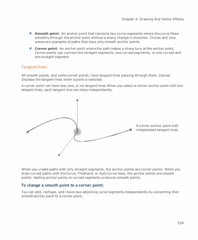
Chapter 4: Drawing And Vector Effects
Smooth point: An anchor point that connects two curve segments where the curve flowssmoothly through the anchor point without a sharp change in direction. Circles and sinewaves are examples of paths that have only smooth anchor points.
Corner point: An anchor point where the path makes a sharp turn at the anchor point.Corner points can connect two straight segments, two curved segments, or one curved andone straight segment.
Tangent lines
All smooth points, and some corner points, have tangent lines passing through them. Canvasdisplays the tangent lines when a point is selected.
A corner point can have one, two, or no tangent lines.When you select a corner anchor point with twotangent lines, each tangent line can move independently.
A corner anchor point withindependent tangent lines
When you create paths with only straight segments, the anchor points are corner points. When youdraw curved paths with the Curve, Freehand, or Auto Curve tools, the anchor points are smoothpoints. Adding anchor points to curved segments produces smooth points.
To change a smooth point to a corner point:
You can edit, reshape, and resize two adjoining curve segments independently by converting theirsmooth anchor point to a corner point.
339

Canvas 12 User Guide
1. With the object in edit mode, click the anchor point to reveal its tangent lines.
2. Press Tab and drag one of the handles tomove one of the tangent lines. The tangent linepivots at the anchor point and affects only one side of the anchor point.
Tab-click a corner point’s handle to snap theother tangent line into alignment and smooththe path
340
Chapter 4: Drawing And Vector Effects
To change a corner point to a smooth point:
To smooth out a sharp turn in curved segments, change the corner point between them to a smoothpoint.
The corner point must have two tangent lines for this procedure. If it has fewer than two,first add tangent lines to the point.
1. With the object in edit mode, click the anchor point to display its tangent lines.
2. Tab-click the handle of the tangent line you want to keep in place; the other tangent linesnaps into alignment.
Adding and removing tangent lines
An anchor point can have as many as two tangent line segments. Corner points can have one, two, orno tangent lines, and smooth points must have two. You can quickly convert a smooth point to acorner point by deleting one of its tangent lines. Also, to convert a corner point with one or notangent lines to a smooth point, you must add tangent lines.
To add a tangent line:
1. In path edit mode, select an anchor point with one or no tangent lines. The anchor pointcannot be an endpoint with one tangent line, because endpoints can have only one tangentline.
2. Press Tab and drag away from the anchor point to place a new tangent line segment. You canalso right-click and choose Add Handle in the context menu. As you do this, the new tangentline begins altering the segment based on how you drag to position the tangent line.
3. Repeat the previous step to add a second tangent line.
To delete tangent lines:
1. In edit mode, click an anchor point to display its tangent lines.
2. Depending on how you want to edit the anchor point, do one of the following:
To delete one tangent line: Right-click the tangent line handle and chooseDeleteHandle in the context menu. You must use this method for anchor points with only onetangent line, and to delete one of two tangent lines attached to an anchor point.
To delete an endpoint’s tangent line: You can also Tab-click the anchor point.
341
Canvas 12 User Guide
To simultaneously delete both tangent lines of an anchor point: Tab-click thepoint.
Straightening curve segments
Straighten a curved segment by selecting it and using the Straighten command in the context menu.This command deletes the tangent line(s) that curve the segment.
To straighten a segment:
1. With the object in edit mode, right-click the curved segment that you want to straighten.
2. ChooseStraighten in the context menu.
Reshaping curve segments
To adjust the shape of a curve, in addition to moving points and segments along the path itself, youcan adjust the tangent lines that control the curve. The angle of the tangent line affects the curveshape, while the length of the tangent line affects the size of the segment.
At a smooth anchor point, adjusting the angle of a tangent line affects the curves on both sides of theanchor point. At a corner anchor point, you can reshape the segments on each side independently(see "Reshaping paths by editing anchor points" on page 338).
To reshape a curved segment:
1. With the object in edit mode, click one of the segment’s anchor points to display its tangentlines.
2. Drag the handle of the tangent line to change the shape of the associated curve. In the caseof a smooth point, the tangent line affects both adjacent curve segments.
342
Chapter 4: Drawing And Vector Effects
Path editing shortcuts
To do this Shortcut
Add an anchor point Ctrl-click path
Delete an anchor point Ctrl+Shift-click anchor point
Change the length of the tangent lines on bothsides of a smooth anchor point at the same time
Ctrl-drag tangent line handle
Constrain tangent line to 45-degree increments Shift-drag tangent line handle
Move tangent line segment independently(change anchor point from smooth to cusp)
Tab-drag tangent line handle
Align tangent line segments (change corner pointwith two tangent lines to smooth point)
Tab-drag tangent line handle
Add tangent line to an anchor point Tab-drag an anchor point
Delete an anchor point’s tangent lines Tab-click the anchor point or endpoint
Close an open path Alt-click an endpoint
Reshape a segment without changing the tangentline angles
Press Tab and drag the segment
Reshape A segment and adjacent segments Press Alt and drag a segment
Converting objects and text to paths
Some vector objects have specialized properties and unique edit modes instead of the standard pathedit mode; e.g., you cannot directly edit the path segments of dynamic objects, concentric circles,grids, multigons, spirals, and objects modified by the Envelope or Extrude commands; however, youcan convert these objects to paths so you can edit them the same as any other vector object.
If you create paths from a specialized vector object, the new shape does not have the same uniqueediting capabilities as the original; e.g., if you convert a Multigon star object to paths, you can nolonger use the edit handles that let you adjust the depth and twirl of the points. Similarly, placeddynamic objects are no longer linked to their parent objects in the Symbol Library palette after youconvert them to paths.
You can also convert text so you can reshape characters as vector objects. This has the benefit ofmaking the characters independent of their fonts; the font is no longer required to view and print thecharacters properly. However, once you convert text to paths, you can no longer perform textoperations, such as editing, spell-checking, and formatting, on the text. Also, characters with
343

Canvas 12 User Guide
“holes” in them (such as a, b, d, e, g, o, p, r, and q) are converted to composite paths, which cannotbe extruded.
To convert an object to paths:
1. Select the object you want to convert.
2. Choose Path | Convert To Paths. Canvas converts the object to one or more paths.
To convert objects to simple paths:
This operation facilitates the rapid conversion of vector objects into a simple path. Now any Canvasobject or a group of objects can be converted into simple paths. At the same time, these objects willmaintain their Canvas inks settings and stroke types.
The Convert to simple paths command breaks down everything Convert to path does not. It alsobreaks down strokes and inks to simple, yet editable, Bézier paths and polygons.
1. First select the object.
2. Choose Path | Convert to Simple Paths.
3. After completing this operation, choose Object | Ungroup.
At this point, all high level drawing features that are contained in the object are reduced toindividually editable polygon and Bézier objects.
Outlining path stroke
An illustrator may find it necessary to outline a path stroke when working with logos, intricateartwork, or traced images, etc., especially if the illustrations will be resized.
344

Chapter 4: Drawing And Vector Effects
Illustration with a 6—point strokeresized to be 50% smaller
Even when reduced, the objectmaintains stroke size
Illustration with a converted strokeresized by 50%
After conversion, the stroke size is nolonger a factor when reducing objects
To outline a path stroke:
Select the vector object and choose Path | Outline Path Stroke.
You can apply this command to more than one selected vector object or even a groupedobject.
345
Canvas 12 User Guide
Original illustration Illustration with outlined path stroke
To ungroup objects made of multiple paths:
When you convert multiple objects, characters, or specialized vector objects to paths, Canvascreates a separate path for each shape and groups them.
ChooseObject | Ungroup to separate them.
For example, if you convert a five-letter word to paths, the resulting object is a group of five paths.To edit just one of the five paths, first choose Object | Ungroup. Or, use the Direct Selection tool toselect one path without ungrouping.
Making and breaking composite paths
Create openings in a filled path by incorporating multiple paths into a single, composite path. Areasbetween the paths and areas where the paths intersect are transparent.
To create a composite path from multiple paths:
Select the paths you want tomake into a composite path. Choose Object | Make Composite or clickthe Make Composite button in the Properties bar.
To separate a composite path:
Select the composite path and chooseObject | Break Composite or click the Break Compositebutton in the Properties bar.
346

Chapter 4: Drawing And Vector Effects
To symmetrically resize path points:
When using the Symmetrical Drag feature, you can easily create a symmetrical design from a circle,rectangle, or a complex group of objects.
1. Select an object and place it into path edit mode.
2. Right-click to open the context menu.
You also have the ability to select all of the control points, and drag. Doing so will allowyou to quickly resize the object while retaining proper object constraints.
3. Choose Enable Symmetrical Resize.
4. Release themouse and select any of the object’s control points.
5. Drag to create a new shape for the object.
When you drag the selected control points, notice that the shape is resized from the center of theobject.
Dragging will resize the object
347

Canvas 12 User Guide
Simplifying vector paths
The Reduce Points command lets you simplify vector paths by reducing the number of anchor pointsin the path.
Simplifying is a good practice when paths you import or create have a very high number of anchorpoints. These paths can cause slow printing or printer errors, especially when memory is limited. Ifyou have problems printing a complex vector path, try simplifying it.
Use the Reduce Points command when one vector object is in path edit mode, or when one or morevector objects are selected.
Reduce Points works with objects created with the Curve, Auto Curve, Freehand, Smooth Polygon,and Polygon tools. You can apply it to objects created with other tools if you use the Path | Convert toPaths command to convert the objects to vector paths.
Reduce Points is not available when specialized vector objects (Concentric Circles, Smart Shapes,Multigons, and similar objects) are selected or in edit mode. These objects must be converted topaths to simplify them.
To use the Reduce Points command:
1. Select one or more vector objects, or place one object in path edit mode (select it and chooseObject | Edit). In edit mode, you can select three or more anchor points and apply ReducePoints.
2. Choose Path | Reduce Points.
3. In the dialog box, drag the slider to set the relative number of anchor points to use for thepath.
Loose: Leaves fewer points in the path by tracing the original path more smoothly.
Tight: Removes fewer points by tracing the original more closely. When more points areremoved, the change in the path can be greater.
4. Click OK tomodify the path.
Converting polygons to Bézier objects
The Fit Bézier command changes a polygon to a Bézier curve path. This command can be applied to asingle selected polygon that is not in edit mode. Fit Bézier is useful when you want to use handlesattached to smooth anchor points to “bend” straight path segments into curves. Using Fit Bézier addshandles to all the corner points (which do not have handles) that define a polygon.
348
Chapter 4: Drawing And Vector Effects
Using this command can have varied results, depending on the settings you use. You can convert apolygon without changing its shape. Or, use the command to smooth the straight segments of apolygon into gentle curves.
To use the Fit Bézier command:
1. Select a polygon (open or closed).
A polygon can be created with the Polygon tool, Smooth Polygon tool, or Curve tool if the pathhas only corner points, not smooth points. Objects created with the Rectangle tool or Linetool can be converted to polygons with the Path | Convert to Paths command.
2. Choose Path | Fit Bézier.
3. In the dialog box, use these the sliders to adjust the following conversion settings:
Loose-Tight: Controls how closely the modified path will conform to the original path.Tight results in little deviation from the original path. Loose allows themodified path to besmoother and deviate farther from the original.
Round-Sharp: Controls how many corners will become rounded in themodified path.Sharp preserves corners where segments meet at acute angles. Round allows all cornersto become rounded.
These settings can interact and produce similar results at different slider positions; e.g.,setting one slider at Tight and the other at Round can produce a path that closelymatches the original, but with all corners being rounded. Setting one slider at Loose andthe other at Sharp can result in a path that overall is smoother, but which has somecorners that are not smoothed at all.
4. Click OK when you’re done. Canvas modifies the object based on the settings you specified.
Joining open vector objects
The Smart Join function lets you join two or more open vector objects together to become a singleobject.
To join objects together:
1. Select the open vector objects you want to join by holding down the Shift key and clickingobjects.
If you do not select any objects, the command will be applied to all open objects in thedocument.
2. Choose Path | Smart Join.
3. Select the Smart Join options.
349

Canvas 12 User Guide
4. Do one of the following:
Click Apply. The objects are joined according to the Smart Join options, but the dialog boxremains open. If you want to change the options you can do so and click Apply again, oryou can click Cancel to discard the changes and close the dialog box.
Click OK. The objects are joined according to the Smart Join options, and the dialog box isclosed.
Smart Join options
Max distancebetween 2 points
Select the maximum distance allowed between two points in order to jointhem. For example, if you set the maximum distance to 3 pt, end pointswhose distance between two given lines are within 3 points will bejoined.
Max segment atcrossed point
Select the maximum length of a segment from the point where the twocrossed lines join. Unnecessary segments extended from this point aretrimmed.
Source LineAttributes
Select the types of line attributes for lines that can be joined:
Polygons only: Allow joins between polygons only. This includeslines.Beziers only: Allow joins between beziers only. This includesarcs.Both: Allow joins between beziers and polygons, or a combinationof the two types.Matched Stroke: Select this check box to only join lines with thesame stroke. This includes dashes.Matched Pen Color: Select this check box to only join lines withthe same pen color.
Result Line Attributes Select the line attributes to be applied to the joined object:
Most Front: Use the line attributes of the front-most object.Most Behind: Use the line attributes of the rear-most object.
Exporting and importing geometric data
Canvas lets you export numerical data about a geometric object to a text file. You can also importgeometric data from a text file or from a .CSV file.
350

Chapter 4: Drawing And Vector Effects
Exporting geometric data
To export geometric data:
1. Open a Canvas document that contains simple, geometric vector objects.
2. Choose Path | Geometric Export.
3. In the Geometric Export Options dialog, select the options you want to use.
4. Click OK.
5. In the Geometric Export dialog box, select the location where you want to save the file, type afile name, and click Save.
351
Canvas 12 User Guide
Geometric Export options
File CoordinatesSystem
Displays the current coordinates.
File Coordinates Unit Displays the current document unit.
Delimiter Option Select a delimiter option.
Object Type to Export Select the type of object you want to export.
Objects that are not simple vector objects such as RoundedRectangles, Smooth Polygons, Concentric Circles, Spirals,EasyShapes, Multigons, and Smart Lines should be converted topaths and/or ungrouped. Otherwise, such objects are notexported.
Add a header line todescribe exportsettings
Select this check box to add a line at the top of the file describing theexport settings.
Field Data This section displays the data types that are available to be exported. IftheWrite column has a Yes, the data type will be exported. By default, allthe data types are set to Yes.
If you do not want to export a type of data, click in theWrite column tochange the data type to No.
At least one data type must be set to Yes in order to exportgeometric data.
Save as default If you want to save these settings as your default settings for exportinggeometric data, select this check box.
Importing geometric data
To import geometric data:
1. Open the Canvas document you want to import the geometric data into.
2. Choose Path | Geometric Import.
3. In the Geometric Import Options dialog, select the options you want to use.
4. Click OK.
352

Chapter 4: Drawing And Vector Effects
Geometric Import options
File Select a .TXT or .CSV file to import.
File CoordinatesSystem
Select the document coordinate system.
File Coordinates Unit Select the document unit.
Delimiter Option Select a delimiter option.
Object Type to Import Select the type of object you want to import.
Import data startingfrom line (skipheader)
If the first line or more of the file you are importing is containsinformation describing the export settings, set this to the line numberwhere the geometric data begins. If there is no header information, leavethis as the default.
Pen Unit If you want to import Pen Weight, select a pen unit from the drop-downlist.
Field Data This section displays the data types that are available to be imported. Ifthe Read column has a Yes, the data type will be imported. By default, allthe data types are set to Yes.
If you do not want to import a type of data, click in the Read column tochange the data type to No.
If you want to change a field number, click in the Field # column.
At least one data type must be set to Yes in order to importgeometric data.
Editing views of 3D objects
In Canvas, you can place a 2D view of a 3D object in your document. After you've placed the object,you can edit the view, adjusting the orientation, rotation, zoom, and lighting of the object.
This feature works best with the latest video card drivers. If an object is slow to load,consider updating your video card driver.
353

Canvas 12 User Guide
To place a 2D view of a 3D object:
1. Select the 3D View tool from the Toolbox.
2. Drag and define a rectangular areawhere the view of the 3D object will be placed.
3. In the AutoCAD 3D File Import dialog box, click the Browse button, select the 3D DWG or DXFfile you want to place, then click Open.
4. Click OK.
A 2D view of the object is placed in the document. By default, the object is cached at aresolution of 300 ppi to optimize redrawing.
You can change the resolution of the cached image. Select the object, then enter theresolution in the Res text box in the Properties bar.You can also choose to not cache theobject by deselecting the Cache Object check box.
To modify the view of the 3D object:
1. Double-click the 3D object in your Canvas document.
2. In the 3D View Editor dialog box, use the View, Rotation Angles, and Lighting tools to modifythe view of the object.
3. Click OK.
354

Chapter 4: Drawing And Vector Effects
3D View Editor dialog box
View Controls Adjust the orientation, rotation, and zoomof the object.
Magnifying glass: Select this tool, then click on the previewimage to zoom in. To zoom out, click the tool, then right-click thepreview image.Hand tool: Select this tool, then drag the preview to change thepart of the image that is displayed in the view.Free rotation: Drag the preview image through any angle.X-axis rotation: Drag the preview image along the X axis.Y-axis rotation: Drag the preview image along the Y axis.Z-axis rotation: Drag the preview image along the Z axis.Step rotation: Activated when the X-axis, Y-axis, or Z-axisrotation icon is selected. Set the step of rotation that will be appliedwith the Down and Up icons.Zoom controls: Zoom in or out using the zoom icons, or enter aspecific level of zoom.Revert: Click this button to revert the transform (rotation,positioning, and zoom) of the viewed object to the state it was inbefore you opened the 3D View Editor.Reset: Click this button to reset the transform of the viewed objectto the default setting in the original file.
Rotation Angles Use the Rotation Angles to set the degree of rotation precisely.
Lighting Select the Lighting check box to adjust the lighting.
Light color: Set a color of the light source by dragging R, G, and Bsliders or entering in numerical values, or select a color by clickingon the color spectrum bar with the color picker mouse pointer.Light source: Enter X, Y, and Z coordinates to set the position ofthe light source. Also, you can drag the light source handle in thePreview window to set X and Y positions intuitively.Back/Front slider: Drag the slider to set the depth of the lightsource along the Z axis (0 – 100).Light intensity: Drag the slider to adjust the overall brightness ofthe light source.Ambient light color: Set the color of the ambient light. Thedefault color is white.
355
Canvas 12 User Guide
Wireframe Displays the preview image in wireframe.
Background Select the background color of the image. By default the color comesfrom the original file, or it's set to black.
Only opaque, solid colors can be used. ie. Transparent is not avalid background color.
Precision drawing & dimensioning
This section describes precision drawing tools and techniques that can help you create scaledrawings, floor plans, architectural designs, and other types of technical drawings. This sectionexplains how to:
Display size information as you draw.
Set up the scale for scale drawings.
Add dimension objects to illustrations.
Use Smart Mouse to align objects.
Some of the techniques described elsewhere in this book also apply to precision drawing. Forinformation on document setup and using rulers, see "Document setup" on page 68.
Setting up a document’s measurement scale
Canvas offers a variety of options for creating scale drawings. You can use the Add unit feature todefine a new unit of measurement for a particular document or redefine an existing unit (see "Addingand modifying units of measurement" on page 75). You can also set up a ruler to control the scale ofan entire document as well as customize scale settings for individual dimension objects (see "Settingup rulers" on page 74). Other settings affect the format of measurement and position data.
The following settings affect themeasurement of objects in a document:
Rulers: Set up a document’s overall drawing scale using the Ruler manager and documentscale. The document scale affects all object measurements, including those madewith theDimensioning tools. The document scale also affects data in the Properties bar and ObjectSpecs palette (see "Setting up rulers" on page 74 and "Set document scale" on page 78).
356
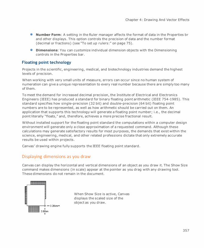
Chapter 4: Drawing And Vector Effects
Number Form: A setting in the Ruler manager affects the format of data in the Properties brand other displays. This option controls the precision of data and the number format(decimal or fractions) (see "To set up rulers:" on page 75).
Dimensions: You can customize individual dimension objects with the Dimensioningcontrols in the Properties bar.
Floating point technology
Projects in the scientific, engineering, medical, and biotechnology industries demand the highestlevels of precision.
When working with very small units of measure, errors can occur since no human system ofnumeration can give a unique representation to every real number because there are simply too manyof them.
Tomeet the demand for increased decimal precision, the Institute of Electrical and ElectronicsEngineers (IEEE) has produced a standard for binary floating point arithmetic (IEEE 754-1985). Thisstandard specifies how single-precision (32 bit) and double-precision (64 bit) floating pointnumbers are to be represented, as well as how arithmetic should be carried out on them. Anapplication that supports this technology will generate a floating point number; i.e., the decimalpoint literally “floats,” and, therefore, achieves a more precise fractional result.
Without installed support for the floating point standard the computations within a computer designenvironment will generate only a close approximation of a requested command. Although thesecalculations may generate satisfactory results for most purposes, the demands that exist within thescience, engineering, medical, and other related professions dictate that only extremely accurateresults be used within projects.
Canvas’ drawing engine fully supports the IEEE floating point standard.
Displaying dimensions as you draw
Canvas can display the horizontal and vertical dimensions of an object as you draw it. The Show Sizecommand makes dimensions (in scale) appear at the pointer as you drag with any drawing tool.These dimensions do not remain in the document.
When Show Size is active, Canvasdisplays the scaled size of theobject as you draw.
357

Canvas 12 User Guide
To display dimensions when you use drawing tools:
Choose Layout | Display | Show Size. When you select a drawing tool and drag the pointer in anillustration, the object’s vertical and horizontal measurements appear at the pointer.
The Show Size option can also be toggled in the Display Options manager in theConfiguration Center.
To turn off the dimensions display:
Choose Layout | Display | Hide Size.
Using the Dimensioning tools
You can easily add formatted dimensions to documents with the Dimensioning tools. These tools canmeasure horizontal, vertical, oblique and perpendicular distances; measure diameter, radius, angle,area, and perimeter; and mark the centers of arcs and ovals.
The dimensioning tools are grouped in a single palette (see "Tool palettes" on page 23). The Linear,Chain, and Baseline tools allow you to create horizontal, vertical, or oblique dimensions, dependingon the position of the cursor upon creation.
In addition, when using the Chain and Baseline Dimensioning tools, you define the first two points asyou would for a Linear dimension. Then, just click on every point you want to add to the dimension,and the tool creates the dimension object automatically. The result of using the Chain or BaselineDimensioning tool is one single object. The current limit for Chain Dimensions is 16.
Baseline dimensions are a series of measurements made from a common starting point.Chain dimensions are a series of measurements in a row.
Create dimension objects that conform to industry standards, including ANSI, DIN and JIS. You canalso customize the standard settings — the size of lines, gaps, text, and tolerances—and then savethese settings as new standards (see "Using industry standards for dimension objects" on page364).
358
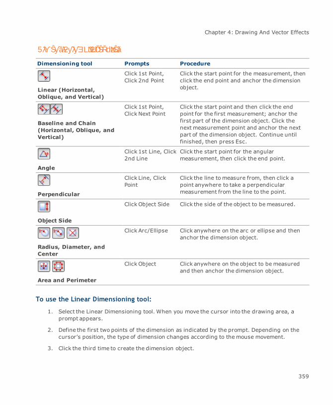
Chapter 4: Drawing And Vector Effects
Dimensioning tool Prompts Procedure
Linear (Horizontal,Oblique, and Vertical)
Click 1st Point,Click 2nd Point
Click the start point for the measurement, thenclick the end point and anchor the dimensionobject.
Baseline and Chain(Horizontal, Oblique, andVertical)
Click 1st Point,Click Next Point
Click the start point and then click the endpoint for the first measurement; anchor thefirst part of the dimension object. Click thenext measurement point and anchor the nextpart of the dimension object. Continue untilfinished, then press Esc.
Angle
Click 1st Line, Click2nd Line
Click the start point for the angularmeasurement, then click the end point.
Perpendicular
Click Line, ClickPoint
Click the line tomeasure from, then click apoint anywhere to take a perpendicularmeasurement from the line to the point.
Object Side
Click Object Side Click the side of the object to be measured.
Radius, Diameter, andCenter
Click Arc/Ellipse Click anywhere on the arc or ellipse and thenanchor the dimension object.
Area and Perimeter
Click Object Click anywhere on the object to be measuredand then anchor the dimension object.
To use the Linear Dimensioning tool:
1. Select the Linear Dimensioning tool. When you move the cursor into the drawing area, aprompt appears.
2. Define the first two points of the dimension as indicated by the prompt. Depending on thecursor’s position, the type of dimension changes according to themouse movement.
3. Click the third time to create the dimension object.
359
5ƛƳŜƴǎƛƻƴƛƴƎ LJNJƻŎŜŘdzNJŜǎ
Canvas 12 User Guide
To use the Chain and Baseline Dimensioning tools:
1. Select either the Chain or Baseline Dimensioning tool. When you move the cursor into thedrawing area, a prompt appears.
2. Define the first two points of the dimension as indicated by the prompt. Depending on thecursor’s position, the type of dimension changes according to themouse movement.
3. Click the third time to create the first dimension.
4. Click on other points to add them to the dimension object.
Types of dimensioning tools and measurements
Use the dimensioning tools to add measurements to illustrations. Different tools let you createdifferent types of dimension objects.
Baseline and chain dimensioning tools create a single dimension object. Baseline dimensions containseveral measurements from a common starting point. Chain dimensions are a series ofmeasurements.
Vertical
Oblique
Radius
Diameter
Vertical Baseline
Oblique (with aligned text)
Vertical Chain
Angle
Horizontal
Using the dimensioning settings
You can customize themeasurement units, scale, arrow position, tolerance text, and other settingsfor dimension objects. Use the Dimensioning settings in the Properties bar. These settings areavailable when you select a Dimensioning tool or have selected a dimension object. Depending on theselected Dimensioning tool or object, the Properties bar will display various settings.
360
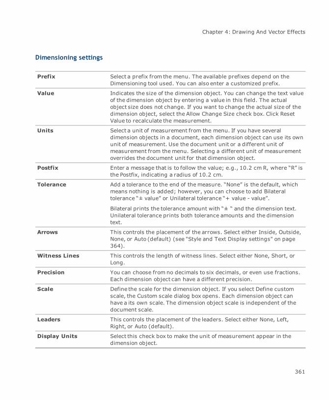
Chapter 4: Drawing And Vector Effects
Dimensioning settings
Prefix Select a prefix from the menu. The available prefixes depend on theDimensioning tool used. You can also enter a customized prefix.
Value Indicates the size of the dimension object. You can change the text valueof the dimension object by entering a value in this field. The actualobject size does not change. If you want to change the actual size of thedimension object, select the Allow Change Size check box. Click ResetValue to recalculate the measurement.
Units Select a unit of measurement from the menu. If you have severaldimension objects in a document, each dimension object can use its ownunit of measurement. Use the document unit or a different unit ofmeasurement from themenu. Selecting a different unit of measurementoverrides the document unit for that dimension object.
Postfix Enter a message that is to follow the value; e.g., 10.2 cm R, where “R” isthe Postfix, indicating a radius of 10.2 cm.
Tolerance Add a tolerance to the end of themeasure. “None” is the default, whichmeans nothing is added; however, you can choose to add Bilateraltolerance “± value” or Unilateral tolerance “+ value - value”.
Bilateral prints the tolerance amount with “± “ and the dimension text.Unilateral tolerance prints both tolerance amounts and the dimensiontext.
Arrows This controls the placement of the arrows. Select either Inside, Outside,None, or Auto (default) (see "Style and Text Display settings" on page364).
Witness Lines This controls the length of witness lines. Select either None, Short, orLong.
Precision You can choose from no decimals to six decimals, or even use fractions.Each dimension object can have a different precision.
Scale Define the scale for the dimension object. If you select Define customscale, the Custom scale dialog box opens. Each dimension object canhave a its own scale. The dimension object scale is independent of thedocument scale.
Leaders This controls the placement of the leaders. Select either None, Left,Right, or Auto (default).
Display Units Select this check box to make the unit of measurement appear in thedimension object.
361
Canvas 12 User Guide
Separate Thousands Select this check box if you want to have a comma separator for digitgrouping.
Outside Lines Only Select this check box to keep the dimension object outside of the object.This option applies to Radius and Diameter objects.
Use Secondary Units Select this check box if you want your dimensioning object to display twodifferent units of measurement; e.g., inches and centimeters (cm).Choose the secondary unit of measurement from themenu.
Text Display This controls the placement of the dimension text (see "Text Display" onpage 363).
Standard Select a dimensioning standard from the menu: ANSI, BS-380, DIN, ISO,or JIS. The Standard refers to the length of lines, size of tolerance text,placement of the text, placement of the arrows, etc.
Add Click this button to add a custom dimension standard (see "Newstandard definition" on page 365).
Edit Click this button tomodify a dimension standard (see "New standarddefinition" on page 365).
Remove Click this button to remove the selected dimension standard (see "Todelete a custom standard:" on page 365).
To change the properties of existing dimension objects:
1. Select the dimension object. The settings appear in the Properties bar.
The Properties bar must be displayed to view the Dimensioning settings. If not open,chooseWindow | Show Properties Bar.
2. Make any adjustments with the settings.
You can change the properties of multiple selected dimension objects as long as thedimension objects are of the same type.
To change the settings for dimensioning tools:
1. Select the Dimensioning tool. The settings appear in the Properties bar.
2. Make any adjustments to the tool settings and then create the dimension object (see"Dimensioning settings" on page 361).
362
Chapter 4: Drawing And Vector Effects
Attributes of dimension objects
When you are using a dimensioning tool, the pen ink of the dimension object appears blackwith a 1-pt stroke; however, once you complete the object, the pen ink switches to the current ink and strokesettings. By default, the dimension text is 10 pt and uses Arial. In addition, the current stroke color isapplied to the dimension text.
You can change the current ink, stroke, and text settings for new dimension objects, and you canchange these settings for existing dimension objects.
To change the appearance of a dimension object:
Select the object and use the Presets palette to select ink color, pen size, and arrows for thedimension object.
Dimension objects can still display arrows if all the preset arrows have been deleted fromthe Arrow tab in the Presets palette.
To change attributes for new dimension objects:
Make sure that no objects are selected in the document, and then use the Presets palettes tochange the current stroke and ink settings for new objects and text.
To change the text attributes of a dimension object:
The Properties bar allows you quick access to text formatting options for various dimensionobjects.
You can scroll the Properties bar if all the options are not visible. Arrows appear on the leftand right indicating that other options are available.
Text Display Refers to the placement of dimension text in relation to the object.
Horizontal Text is aligned horizontally in the dimension object.
Aligned Text is aligned with the angle of the dimension arrows.
Above Text runs above the dimension arrows.
Below Text runs below the dimension arrows.
Font & Size Select a new font and font size for the text from the menus.
Style Click the buttons to apply a style to the text (Bold, Italic, Underline, andFrame).
363

Canvas 12 User Guide
You can also change the font, size, and styles by using the Textmenu or Type palette.
Style and Text Display settings
Use the following style options in the Properties bar to customize the appearance of dimensionobjects.
Text Always Centered Select this option to keep the text between the arrows. Must be off todrag dimension text outside the witness lines.
Frame Text Turn this option on to frame the dimension text.
Use Fill Color for Text Select this check box if you want the dimension text to use the fill colorrather than frame color of the object.
Linking dimensions to measured objects
Since dimension objects aren’t attached to the objects theymeasure, dimensions do not changewhen you resize objects you have measured. However, you can group a dimension object and theobject that it measures. When you do this and then resize the object, the dimension changesaccordingly.
To group an object and a dimension object:
Select the dimension object and themeasured object and choose Object | Group.
Using industry standards for dimension objects
If you want to use industry standard settings for dimension objects, open the Standards menu in theProperties bar. Select a dimensioning standard from the menu: ANSI, BS-380, DIN, ISO, or JIS. TheStandard refers to the length of lines, size of tolerance text, placement of the text, placement of thearrows, etc.
Choose from five standard measurement systems:
ANSI: American National Standards Institute
DIN: Deutches Institut für Normung
BS-380: British Standards Institute
364
Chapter 4: Drawing And Vector Effects
ISO: International Organization for Standardization
JIS: Japanese Industrial Standard
To add a custom standard definition:
1. Click the Add button.
2. In the New Standard Definition dialog box, use the controls to create and definedimensioning standards (see "New standard definition" on page 365).
New standard definition
Once defined, custom standards appear in the Standard menu in the Properties bar.
Standard Name Enter a name for the new standard.
Units Select the unit of measurement that you want to use for all settings inthe dialog box.
Extension Set the length of the witness lines’ extensions and the center lineextension.
Gap Set the size of the gap between the witness lines and measurementpoints on objects; the gap between the center extension and centerpointmark; and the gap between the dimension text and dimensionarrows.
Length Set the length of the arrow lines (applies only when arrows are outsidethe witness lines); the length of center extension lines’ leadercharacters; and the length of the center extension line.
Tolerance Scale The size of tolerance text and space between tolerance text, as apercentage of the dimension text size and spacing.
To edit a standard definition:
1. Select a dimensioning standard from the menu.
2. Click the Edit button.
3. In the Edit Standard Definition dialog box, edit the settings.
To delete a custom standard:
1. Open the Standards menu.
2. Select the custom standard definition to be removed.
365
Canvas 12 User Guide
3. Click the Remove button.
Using Smart Mouse for precise alignment
Smart Mouse is a drawing aid that can help the cursor precisely snap to a point on another objectwhen you are drawing. Snap constraints like Smart Mouse are particularly useful when creatingtechnical illustrations or documents in which micron-precision is paramount since it can snap thepointer to the corners, edges, and other points of objects.
Turn off Snap To Grid by choosing Layout | Snap To | Grid. If there is no checkmark, theoption is already turned off. If Snap To Grid is on, the pointer will snap to the grid and not toactive Smart Mouse constraints.
To open the Smart Mouse palette:
Choose Layout | Smart Mouse or Window | Palettes | Smart Mouse.
Types of Smart Mouse constraints
The Smart Mouse tool has 14 types of constraints for your use. The constraints make the pointer (andobjects that you draw or drag) snap to corners or centers of objects, even divisions (such as themidpoints) of object fractions, specified lengths or angles, horizontal, vertical, or diagonalmovement, tangential or perpendicular alignment with objects, or edges of vector objects.
Relative constraints: Indicate the relationship between the beginning position and currentposition when you draw or drag an object. These constraints can display indicators toindicate a constraint is met. The relative constraints are: Horizontal, Vertical, Diagonal,Angle, Multiple Angle, Length, Parallel, and Tangential & Perpendicular.
Absolute constraints: Indicate the relationship between the pointer and objects. Theseconstraints (except Object Edges) can display indicators to show a constraint is met. Theabsolute constraints are: Object Corners, Object Fractions, Polygon & Bézier Anchors,Polygon Fractions, and Object Edges.
366
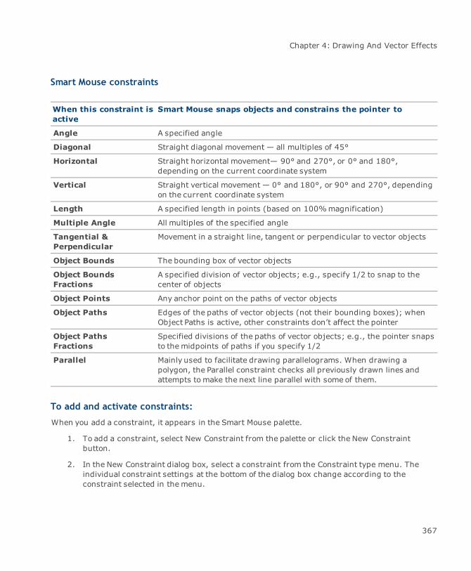
Chapter 4: Drawing And Vector Effects
Smart Mouse constraints
When this constraint isactive
Smart Mouse snaps objects and constrains the pointer to
Angle A specified angle
Diagonal Straight diagonal movement — all multiples of 45°
Horizontal Straight horizontal movement— 90° and 270°, or 0° and 180°,depending on the current coordinate system
Vertical Straight vertical movement — 0° and 180°, or 90° and 270°, dependingon the current coordinate system
Length A specified length in points (based on 100%magnification)
Multiple Angle All multiples of the specified angle
Tangential &Perpendicular
Movement in a straight line, tangent or perpendicular to vector objects
Object Bounds The bounding box of vector objects
Object BoundsFractions
A specified division of vector objects; e.g., specify 1/2 to snap to thecenter of objects
Object Points Any anchor point on the paths of vector objects
Object Paths Edges of the paths of vector objects (not their bounding boxes); whenObject Paths is active, other constraints don’t affect the pointer
Object PathsFractions
Specified divisions of the paths of vector objects; e.g., the pointer snapsto themidpoints of paths if you specify 1/2
Parallel Mainly used to facilitate drawing parallelograms. When drawing apolygon, the Parallel constraint checks all previously drawn lines andattempts tomake the next line parallel with some of them.
To add and activate constraints:
When you add a constraint, it appears in the Smart Mouse palette.
1. To add a constraint, select New Constraint from the palette or click the New Constraintbutton.
2. In the New Constraint dialog box, select a constraint from the Constraint type menu. Theindividual constraint settings at the bottom of the dialog box change according to theconstraint selected in themenu.
367

Canvas 12 User Guide
For this constraint Enter this value
Object BoundsFractions, ObjectPaths Fractions
Number of divisions; e.g., type 2 if you want the constraint to snapto themiddle (1/2 point) of an object or object path.
Angular Angular measurement in degrees.
Length The distance
All constraints require a Snap Tolerance, which is indicated in points. Snap Toleranceis themaximum distance, horizontally or vertically, from a target point at which theconstraint causes the pointer to snap to the target point.
3. Click OK to close the New Constraint dialog box. The constraint now appears in the SmartMouse palette. When a constraint is added, the check box is automatically selected indicatingthat the constraint is active.
Priority of constraints
When multiple constraints are active, the constraint at the top of the constraint list takes precedence.When a new constraint is added, it appears at the bottom of the constraint list. To change the priorityof a constraint, drag it to a new position in the list.
To activate a constraint:
In the Smart Mouse palette, select the constraint’s check box.
To deactivate a constraint:
In the Smart Mouse palette, deselect the constraint’s check box.
To modify an active constraint:
Select the active constraint. The individual constraint settings appear at the bottom of the palette.Make any changes to the constraint and press Enter.
To remove a constraint:
Select the constraint in the palette and then click the Trash icon. You can also select theconstraint and chooseRemove Constraint from the palette menu. Choose Remove All from thepalette menu to delete all current active constraints.
368
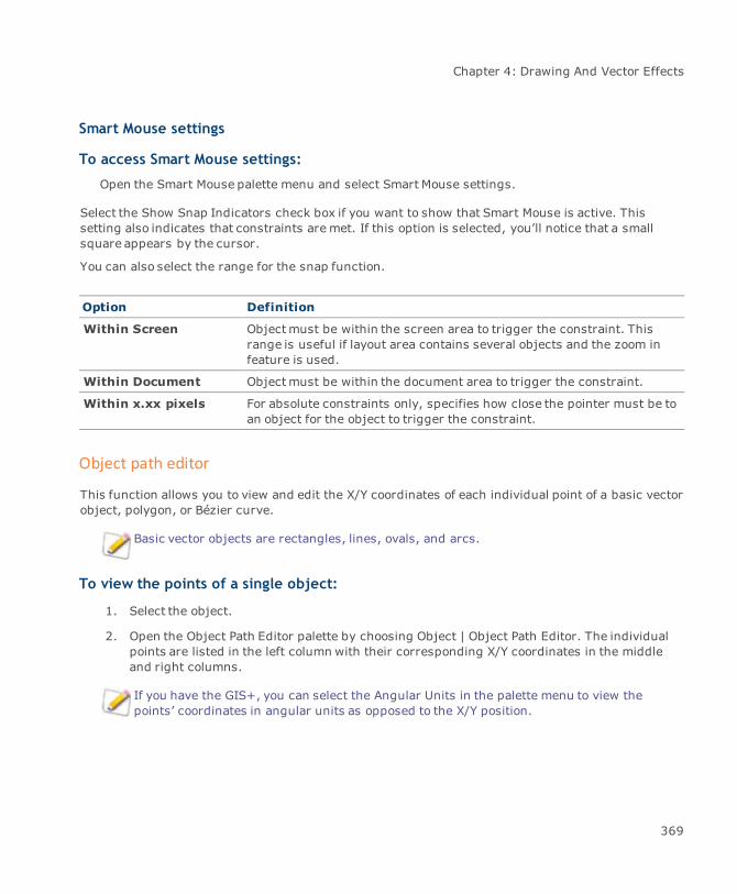
Chapter 4: Drawing And Vector Effects
Smart Mouse settings
To access Smart Mouse settings:
Open the Smart Mouse palette menu and select Smart Mouse settings.
Select the Show Snap Indicators check box if you want to show that Smart Mouse is active. Thissetting also indicates that constraints aremet. If this option is selected, you’ll notice that a smallsquare appears by the cursor.
You can also select the range for the snap function.
Option Definition
Within Screen Objectmust be within the screen area to trigger the constraint. Thisrange is useful if layout area contains several objects and the zoom infeature is used.
Within Document Objectmust be within the document area to trigger the constraint.
Within x.xx pixels For absolute constraints only, specifies how close the pointer must be toan object for the object to trigger the constraint.
Object path editor
This function allows you to view and edit the X/Y coordinates of each individual point of a basic vectorobject, polygon, or Bézier curve.
Basic vector objects are rectangles, lines, ovals, and arcs.
To view the points of a single object:
1. Select the object.
2. Open the Object Path Editor palette by choosing Object | Object Path Editor. The individualpoints are listed in the left column with their corresponding X/Y coordinates in the middleand right columns.
If you have the GIS+, you can select the Angular Units in the palette menu to view thepoints’ coordinates in angular units as opposed to the X/Y position.
369
Canvas 12 User Guide
To view the points of multiple objects:
1. Press Shift and double-click each object to place it in edit mode.
2. Open the Object Path Editor (Object | Object Path Editor). The Curve menu is now active.
3. Select the curve whose points you want to appear. The curve number in themenu isaccording to the stacking order. The individual points are listed in the left column with theircorresponding X/Y coordinates in themiddle and right columns.
To edit X/Y coordinates:
1. Click in the X or Y field of the point to be modified.
2. Enter the new coordinate.
3. Press Enter.
To copy X/Y coordinates:
1. Select the object.
2. Open the menu of the Object Path Editor palette.
3. Select Copy.
4. Paste the coordinates in the other application.
To paste as polygon or Bézier:
With the Object Path Editor, you can create a polygon or Bézier curve with point values copied from aspread sheet or tab-delimited file.
1. Copy the point values in the spreadsheet or tab-delimited file.
2. Open the menu of the Object Path Editor palette.
3. Select either Paste As Polygon or Paste As Bézier.
To load polygon or Bézier:
With the Object Path Editor, you can create a polygon or Bézier curve with point values found in a.txt, .csv, or .prn file.
1. Open the menu of the Object Path Editor palette.
2. Select either Load Polygon or Load Bézier.
3. Navigate to the file and click Open.
370

Chapter 4: Drawing And Vector Effects
To save a path:
1. Open the menu of the Object Path Editor palette.
2. Select Save Path.
3. Enter a name for the file in the dialog box and navigate to the folder. You can use .txt, .csv,or .prn format.
4. Click Save.
To insert points:
With the Object Path Editor, you can insert points within a path.
1. Place an object into edit mode.
2. Select an anchor point.
3. Open the Object Path Editor palette menu.
4. Select Insert Point.
5. In the Insert New Point dialog box, enter the X/Y coordinates for the new point.
6. Click OK.
Vector effects
Canvas has several special effects that let you develop complex illustrations from basic objects. Youcan apply the effects described in this section to any vector object; some can be applied to textobjects, too (see "Type effects" on page 631). These commands help save time by quickly generatingnew objects and letting you easily modify the appearance of existing objects.
As you apply effects to objects, keep in mind that some of these operations are system memory-intensive and might significantly increase the resource and storage requirements of a document.
Perspective effects
Commands in the Path | Perspectivemenu can be used to modify vector objects. The 1 Side, 2 Sides,and Vanishing Point commands let you slant the bounding boxes of vector objects to align withvanishing points. By applying these commands, you can make vector objects appear to be drawn inperspective views.
371
Canvas 12 User Guide
About the vanishing point
The Perspective commands apply perspective effects based on a vanishing point. There is one globalvanishing point in a Canvas document. When you use the 1 Side or 2 Sides commands, you set thevanishing point by dragging a control handle. When you use the Vanishing Point command, you canset the vanishing point by clicking in the document or entering coordinates.
Using the 1 Side and 2 Sides commands
The 1 Side and 2 Sides commands let you apply perspective effects to vector objects by draggingcontrol handles. To use these commands, select a single vector object or a group of vector objects.These commands are not available if multiple objects are selected, or if a paint or text object isselected.
To apply perspective with 1 Side or 2 Sides:
1. Select a vector object or a group of vector objects.
2. In the Path | Perspective menu, choose 1 Side or 2 Sides.
3. Control handles appear at the corners of the bounding box of the selected object. Drag any ofthe handles to apply the perspective effect. As you drag a handle, guide lines indicate theposition of the vanishing point, which extend beyond the current view.
If you choose 1 Side, the side of the object’s bounding box where you drag a handle willslant to a vanishing point. You can adjust the object’s sides independently.
If you choose 2 Sides, as you drag a handle, the opposite sides of the object’s boundingbox will slant equally toward a vanishing point located along the object’s vertical orhorizontal center axis.
When the pointer is on a control handle, a four-arrow symbol indicates that you can draghorizontally or vertically. To change directions, point to a control handle until the four-arrow symbol appears again.
4. When you finish, press Esc to deselect the object.
372
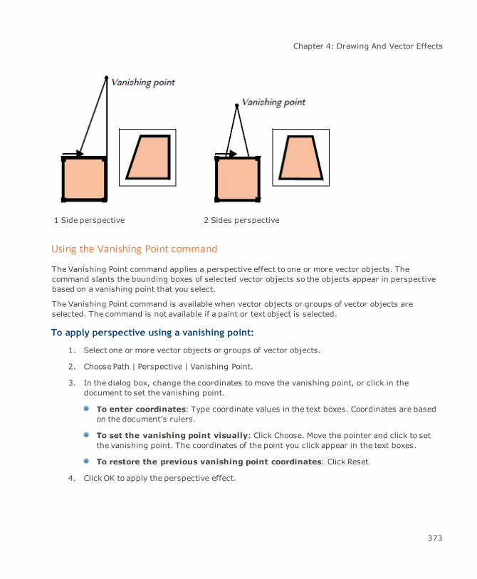
Chapter 4: Drawing And Vector Effects
1 Side perspective 2 Sides perspective
Using the Vanishing Point command
The Vanishing Point command applies a perspective effect to one or more vector objects. Thecommand slants the bounding boxes of selected vector objects so the objects appear in perspectivebased on a vanishing point that you select.
The Vanishing Point command is available when vector objects or groups of vector objects areselected. The command is not available if a paint or text object is selected.
To apply perspective using a vanishing point:
1. Select one or more vector objects or groups of vector objects.
2. Choose Path | Perspective | Vanishing Point.
3. In the dialog box, change the coordinates tomove the vanishing point, or click in thedocument to set the vanishing point.
To enter coordinates: Type coordinate values in the text boxes. Coordinates are basedon the document’s rulers.
To set the vanishing point visually: Click Choose. Move the pointer and click to setthe vanishing point. The coordinates of the point you click appear in the text boxes.
To restore the previous vanishing point coordinates: Click Reset.
4. Click OK to apply the perspective effect.
373

Canvas 12 User Guide
The Effects | Remove Effects command will not remove perspective effects that have beenapplied to objects.
Offsetting paths
Use the Offset Path command to create new objects that follow the path of a vector object.
Composite objects created by the Concentric Circles, Spiral, Cube, Gridmaker, or Multigontools cannot be offset.
An offset object’s path follows the inside or outside of the original object’s path. Specify the offsetdistance and the number of objects to create. You can offset one vector object at a time.
To offset an object:
1. Select a vector object and choose Effects | Offset Path.
2. In the Offset Path dialog box, type the offset distance in the Distance box. In the Copies box,type the number of copies tomake.
3. Click OK to create the offset objects.
Canvas applies the current inks and stroke to offset objects (see "Inks: colors & patterns" on page223 and "Strokes: outline effects" on page 257). The new objects appear in front of the original ifthey are smaller; otherwise, they appear behind it.
The direction of the offset depends on whether you type a positive or negative Distance value.
When you offset an object that has an open path, type a negative value to offset the new object to theinside of the curve. Type a positive value to offset the new object to the outside of the curve.
When you offset an object that has a closed path, type a negative number to offset the new object tothe inside of the original path. Type a positive number to offset the new object to the outside of theoriginal path.
An offset object can differ in shape from the original object, if a large offset distance makes the pathcross itself to follow narrow angles or tight curves of the original object.
Using clipping paths
A clipping path is a special object that creates a frame or window on an object. You can use textobjects and vector objects as clipping paths.
374
Chapter 4: Drawing And Vector Effects
You can apply a clipping path to one or more objects. The clipping path frames the objects to which itis applied. Anything inside the clipping path remains visible, while anything outside the path ishidden, or “clipped.”
If you apply an oval clipping path to a photo, for example, the photo is visible inside the oval, whileany part of the photo outside the oval is not visible.
Since clipping paths are vector objects, clipping effects print smoothly at maximum resolution on anyprinter, including PostScript and non-PostScript devices.
Clipping paths create hard-edged effects. Clipping paths are often used to “cut” photos andillustrations into shapes such as circles or curves. Use text as a clipping path to create the effect oftext characters filled with photos or other graphics (see "Using text as clipping paths" on page 642).
If you want to create feathered or graduated clipping effects, use vector transparency masks andchannel masks instead of clipping paths (see "SpriteLayer effects" on page 666).
To apply a clipping path:
1. Position a text or vector object in front of the objects to be clipped. (select an object andchooseObject | Arrange | Bring to Front to put the clipping object in front of other objects.)
2. Select both the clipping object and objects to be clipped.
3. ChooseObject | Clipping Path | Make to clip the selected objects.
If you want to use a special object (such as a star created by the Multigon tool) as a clipping path, theobjectmust be converted to a vector path first. Select the object and choose Path | Convert to Paths.
If a selected object can’t be used as a clipping path, the Clipping Path | Make command isnot available.
To hide clipping paths:
ChooseObject | Clipping Path | Hide. Canvas makes the strokes of all clipping paths invisible.
To show clipping paths:
ChooseObject | Clipping Path | Show. Canvas shows the clipping paths with a 1-point blackstroke.
To remove a clipping path:
Select the clipping path or a clipped object and choose Object | Clipping Path | Release. Canvasrestores the clipped objects to full view, and the clipping path object appears with its originalattributes.
375

Canvas 12 User Guide
Text in front of paint object
Text clipping path
Editing clipping paths
After applying a clipping path, you can move it and the clipped objects independently. Dragging theclipping path frames a different part of the clipped objects. Dragging a clipped object changes itsposition inside the frame of the clipping path.
You can apply several effects to a clipping path. Select the clipping path and choose Effects |Freeform to display handles that you can drag to skew and rotate the clipping path. You can alsoapply the Fractalize, Rotate, and Flip commands to a selected clipping path.
You can reshape a clipping path in several ways. Select a clipping path and drag its handles tochange the size or shape of its bounding box. To reshape a vector object path, double-click it, orselect it and press Ctrl+E. With the path in edit mode, use path-editing techniques tomove, add, ordelete anchor points. When you finish editing, press Esc to reapply the clipping path.
To edit a text clipping path:
Use the Text tool or double-click the text to put it in edit mode. You can insert and deletecharacters in edit mode. When you finish, press Esc to reapply the clipping path.
To change the formatting of a text clipping path:
Select the clipping path and use the Text menu or the Type palette to change its font, style, size,or other attributes. When a text clipping path is selected, you can use the Spell Check Selectioncommand to check its spelling.
376
Chapter 4: Drawing And Vector Effects
Because clipping paths are special objects, they do not display the pen inks, fill inks, or strokes oftheir original objects. Canvas displays clipping paths with 1-point black strokes (which the ClippingPath | Hide command makes invisible).
If you select a clipping path and change its inks or stroke, Canvas applies the attributes to the object,but the attributes aren’t visible unless you use the Release command to convert the clipping pathback into a vector or text object.
Combining objects
The Combine command in Canvas allows you to create new objects from the intersection of two ormore vector objects. You can outline the overlapping objects, delete all except the overlapping area,subtract the overlapping area, and perform other combinations.
Combine effects
To access the Combine menu, select more than one vector object. To use a combine method, eachselected object must overlap at least one other selected object.
To combine objects:
1. Select two or more objects that you want to combine.
2. Open the Combine menu or use the Combine palette (Effects | Combine).
3. Select a combine method and the effect immediately happens.
Selecting a combine method
The Combine menu contains various methods for combining objects. Some methods require that thepaths of overlapping objects intersect for the effect to be visible or work properly. In addition, somemethods work only with closed vector objects, and not with lines and open curves.
Trim: Trims intersecting lines or arcs by shortening themuntil they meet at a vertex. Youcan trim a line to a line, an arc to an arc, or an arc to a line. In each case, Canvas trims theshorter segments of the intersecting lines and arcs. Trimmed lines and arcs remain separateand retain their attributes.
Trim also trims lines or arcs where they intersect closed vector objects. The vector objects donot change.
If Canvas can’t trim the selected objects, a message tells you that the operation requires at leastone open path.
377
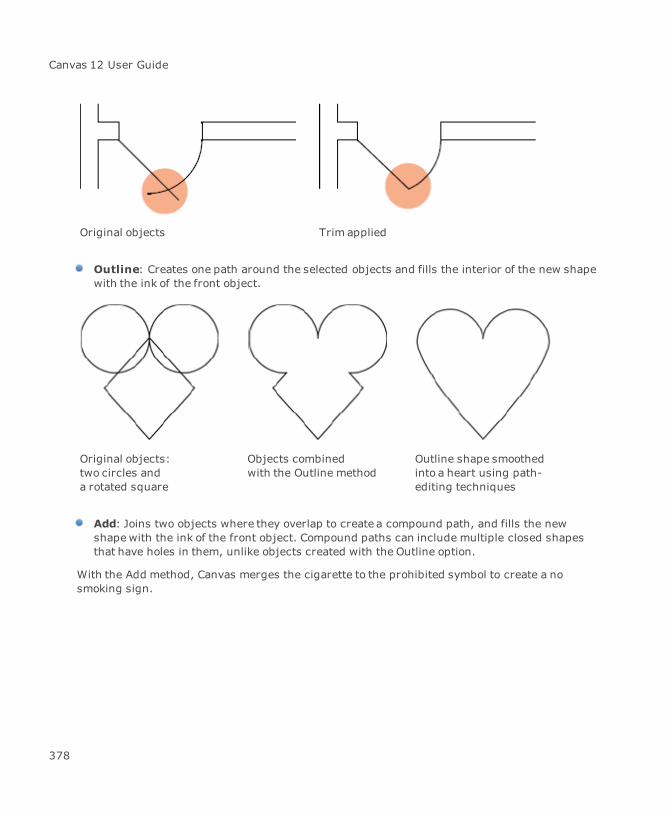
Canvas 12 User Guide
Original objects Trim applied
Outline: Creates one path around the selected objects and fills the interior of the new shapewith the ink of the front object.
Original objects:two circles anda rotated square
Objects combinedwith the Outline method
Outline shape smoothedinto a heart using path-editing techniques
Add: Joins two objects where they overlap to create a compound path, and fills the newshapewith the ink of the front object. Compound paths can include multiple closed shapesthat have holes in them, unlike objects created with the Outline option.
With the Add method, Canvas merges the cigarette to the prohibited symbol to create a nosmoking sign.
378

Chapter 4: Drawing And Vector Effects
Original objects Combined with Addmethod
Intersect: Creates a new object from the intersection of all selected objects and fills thenew object with the ink of the front object. All selected objects must be closed paths andshare a common area.
The Intersect method helps youcreate some useful, basic shapes.Here, the intersection of twocircles (highlighted) results in aneye shape.
Punch: Removes the area where selected objects intersect and fills the new object with theink of the front object. If you select more than two objects, Canvas starts with the backobject and continues forward through the stacking order.
Subtract Front: Removes from the back object the areas of overlapping objects in front.The back object retains its ink attributes.
Create a quick illustration of a holly leaf by combining a group of circles with a rectangle andthen applying the Subtract Front command to that selected group of objects.
379

Canvas 12 User Guide
Create and group objects With objects selected,chooseSubtract Front
Finishedobject
Subtract Back: Removes from the front object the areas of overlapping objects behind it.The front object retains its ink attributes.
Crop: Removes areas of objects that are not behind the top object.
Oval used to crop a vector drawing of anairplane
A symbol-filled oval provides a background
Divide: Creates new objects where selected objects overlap. This option lets you use lines to“cut” other objects in pieces.
Slice: Cuts the path of an object where it intersects with objects in front of it in the stackingorder. The slice method results in two closed paths; e.g., slicing a circle in half with a lineproduces two closed semicircles.
Mix: Creates new objects where selected objects overlap, similar to the Divide option.However, Canvas fills overlapping areas with a new color (the original colors must be solid).To determine the new color, Canvas compares the CMYK values of all the overlapping objects
380

Chapter 4: Drawing And Vector Effects
and uses the highest value of each color. (If you are using RGB colors, Canvas first convertsthe colors to CMYK.) For example:
Cyan Magenta Yellow Black
Color 1 50 30 25 5
Color 2 25 40 20 0
New Color 50 40 25 5
Transparency: Creates new objects where selected objects overlap, and fills overlappingareas with a new RGB color (the original colors must be solid). However, transparency letsyou specify the level of transparency. When you select the Transparency option, enter apercentage in the text box that appears; 100% is completely transparent, and zero isopaque.
Using the Transparency method,the artist created the illusion thatyou can see through the cover ofthe CD case. You can see thebottomof the case through thecover.
If multiple overlapping objects are grouped, Canvas treats the group as a single object anddoesn’t apply the transparency or mix effect within the group.
Blending objects
Using the Blend effect, create gradual transitions in shape, color, and stroke width between two ormore objects. Canvas generates a series of objects (from back-to-front through the stacking order)that appear to transform one object into another.
Canvas can blend solid color inks only. If you blend objects with hatches, symbols, textures,or gradients, Canvas generates the blend objects but doesn’t fill them with an ink.
381

Canvas 12 User Guide
Artists often use blends to create highlights and shadows in vector drawings that provide the illusionof roundness and lighting. In addition, use blends to copy and evenly distribute objects aroundshapes to create borders.
To blend objects:
1. Select two or more vector objects.
2. Choose Effects | Blend.
3. Configure the settings.
4. Click Apply.
Blend Object options
# of shapes The number of objects Canvas creates for the blend. Higher numbersresult in smoother blends.
Rainbow colors Creates a rainbow-like blend of colors between objects. This introducesmore color variations than a standard blend, which uses onlycombinations of the original colors. When you turn on this option, twobuttons appear; choose a clockwise or counter-clockwise path aroundthe color wheel.
Bind to a path Select to use the path of an object (not in the current selection) toarrange blend objects. Click Apply and then you have to choose a path.Click the object to which you want to bind the blend objects.
Point to point Available when blending two objects. This option lets you rotate blendobjects, creating the illusion that one object is twisting into another.When you click Apply, Canvas prompts you to Choose 1st Point; click ananchor point on one object. Canvas then prompts you to Choose 2ndPoint; click an anchor point on the other object. To reverse the blenddirection, Ctrl-click when you choose the two points.
Dynamic Lets you use the Direct Selection tool (hollow arrow) to accelerate,decelerate, expand, contract, and redirect the blend after Canvascreates it. Dynamic blends aren’t available for specialized objects, suchas multigons, spirals, concentric circles, and grids.
Using blends for dimensional effects
By specifying a high number of blend objects, you can create gradual transitions between shapesand colors. With the appropriate settings, colors seem to fade and mix into each other, and the blend
382

Chapter 4: Drawing And Vector Effects
objects do not appear as distinct objects. This effect is often used to add realistic highlights andshadows to objects so they appear three-dimensional.
When configuring the blend settings, remember that the size of the final output affects the numberof shapes required tomake the blend appear smooth. For large posters, you might need to use a lot ofshapes, but fewer shapes are required for small illustrations.
To ensure that blended objects have the same number of anchor points, copy an object, editits shape, and blend between these objects.
In addition, objects that you blend must have the same number of anchor points for the blend toappear smooth. Canvas uses the anchor points to calculate the steps and shapes in a blend; aninconsistent number of anchor points can cause unwanted twists and distortions.
Using blends to create patterns
Although blends are often used to create gradual, smooth transitions between shapes and colors, youcan also use the Blend command to create and evenly space a pattern across a layout. By specifying alow number of shapes and widely spacing the front and back objects, you can make each blendobject a distinct object. This effect can be useful for creating borders and other patterns.
The artist created this border by first creating a flower-like multigon, copying it, and drawing anoval. To distribute the flowers evenly around the oval, the artist selected the two multigons, turnedon the “Bind to a path” option in the Blend palette, specified a relatively low number of shapes (10)for the blend, and chose the oval as the binding path.
383

Canvas 12 User Guide
Enveloping objects
The Envelope command lets you distort shapes and text, as if an illustration was drawn on a rubbersheet and then stretched.
When an object is in envelope edit mode, its bounding box acts like the rubber sheet. Canvasincludes several envelope styles that offer various handles you can use to stretch an object’sbounding box. Using this effect, you can create new shapes, add a sense of motion to an illustration,arrange text so it appears to be painted on a three-dimensional object, or distort an image (see"Envelope effect" on page 546).
The Envelope command distorted thetype to match the contour of the ship’shull
Using envelope templates
Canvas has several envelope templates that you use to instantly distort shapes. The silhouettes in thetemplate scroll list show the distortion created by each template. In addition, you can create yourown envelope templates. After you apply the envelope effect to an object, you can acquire the shapeof the envelope as a template.
To apply an envelope template:
1. Select a vector object.
2. Choose Effects | Envelope to open the Envelope palette.
3. In the palette, choose Template in the menu.
4. Select a preview shape in the scroll list to select it, and click Apply.
384

Chapter 4: Drawing And Vector Effects
To save an envelope as a template:
To store an object’s envelope as a template, you must first use the envelope effect on the object (see"To apply an envelope effect:" on page 385). You can’t acquire a standard vector shape, such as acircle, unless you first apply the envelope effect.
1. Select an object that has been edited using the envelope effect. The object cannot be inenvelope edit mode.
2. Choose Effects | Envelope to open the Envelope palette.
3. In themenu, choose Template.
4. Click Acquire; a preview of the envelope shape appears in the scroll box.
To delete an envelope template:
1. In the Envelope palette, choose Template in the menu.
2. Click a preview shape in the scroll box to select it, and click Delete.
Using envelope styles
In addition to envelope templates, Canvas has six envelope styles that let you edit shapes in differentways. Each style moves and changes the bounding box in a particular way. See "Envelope styles andediting options" on page 386 for information on the attributes of each style.
To apply an envelope effect:
1. Select a vector object.
2. Choose Effects | Envelope to open the Envelope palette.
3. Choose an envelope style in the menu and click Apply.
4. Drag the envelope handles that appear on the bounding box of the object to edit the shape.
385

Canvas 12 User Guide
Envelope styles and editing options
Example Style Number of handles Envelope behavior
Warp Enter the number ofhorizontal and verticalhandles in the textboxes.
Each handle behaves like a path anchorpoint and can move in any direction.
Distort Four Each side of the envelope edit box is astraight line; handles can move in alldirections. This style is useful for creatingperspective.
Straight Line Eight All handles are connected by straightlines. Corner handles are constrained toright-angle movements; side handles canmove in all directions.
Single Cusp Eight Side handles form convex or concavecurves between corner handles. Sidehandles can move in any direction; cornerhandles are constrained to right-anglemovements.
Double Cusp Eight Side handles form S-shaped curvesbetween corner handles. Side handles canmove in any direction; corner handles areconstrained to right-angle movements.
Bézier Eight All handles behave like smooth anchorpoints and can move in any direction.
386

Chapter 4: Drawing And Vector Effects
Extruding objects
The Extrude command lets you create objects that appear to have three dimensions. Extrude vectorand text objects in parallel style, and vector objects in circular and semi-circular (“sweep”) style.
You can rotate and scale extruded objects in three-dimensional space. You can set the placement,intensity, and color of a simulated light source for shading extruded objects. Solid color fill inks canbe applied to extruded objects. Strokes and other inks are not supported.
To extrude an object:
1. Select an object for the extrusion you want to create:
For parallel extrusion, select a text or vector object, or a group object containing one orboth types of objects.
For circular or sweep extrusion, select a vector object.
2. Choose Effects | Extrude to display the Extrude palette.
3. Select a preset or custom extrusion setting:
Using presets: From the preset extrusion palettes, select an extrusion icon to extrudethe selected object. The icons show the angle and position of the extruded object. Canvasuses a default extrusion depth for parallel extrusions, and a default Steps setting forcircular extrusions.
Using custom settings: Click the arrow to expand the palette. Choose an extrusionstyle, lighting color, and other options. Click Apply to extrude the selected object.
4. If you select Circular or Sweep style, an extrusion axis appears (see "Completing a circular orsweep extrusion" on page 388).
Extrusion palette Rotate buttons
387
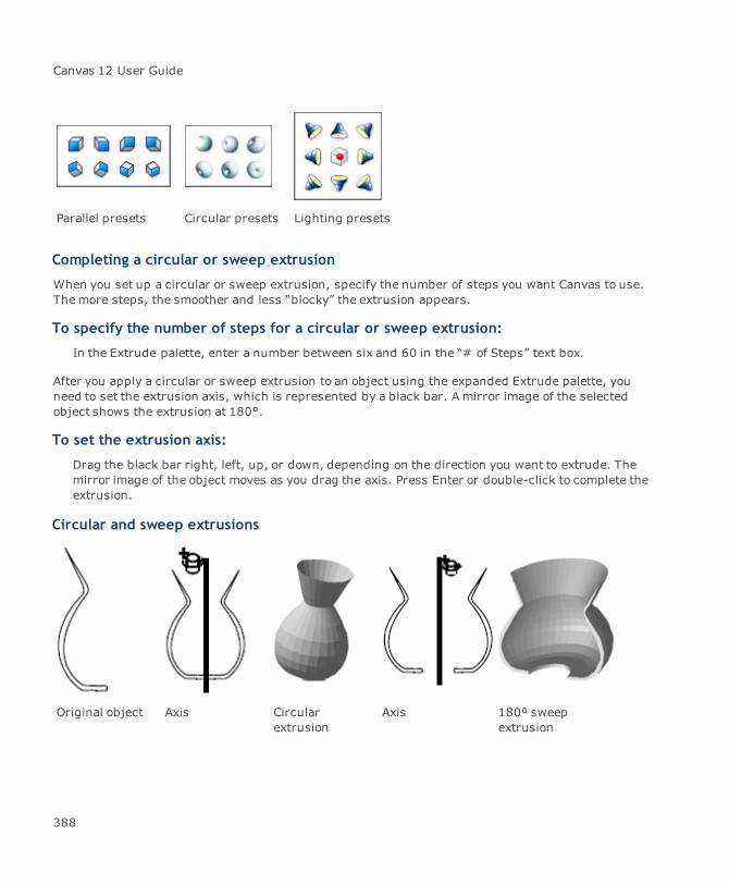
Canvas 12 User Guide
Parallel presets Circular presets Lighting presets
Completing a circular or sweep extrusion
When you set up a circular or sweep extrusion, specify the number of steps you want Canvas to use.Themore steps, the smoother and less “blocky” the extrusion appears.
To specify the number of steps for a circular or sweep extrusion:
In the Extrude palette, enter a number between six and 60 in the “# of Steps” text box.
After you apply a circular or sweep extrusion to an object using the expanded Extrude palette, youneed to set the extrusion axis, which is represented by a black bar. A mirror image of the selectedobject shows the extrusion at 180°.
To set the extrusion axis:
Drag the black bar right, left, up, or down, depending on the direction you want to extrude. Themirror image of the object moves as you drag the axis. Press Enter or double-click to complete theextrusion.
Circular and sweep extrusions
Original object Axis Circularextrusion
Axis 180º sweepextrusion
388

Chapter 4: Drawing And Vector Effects
Extrusion options
Use palettes of extrusion and lighting presets in the Extrusion palette to modify extruded objects. Ifyou expand the Extrude palette, you can use options to control lighting and rotation of extrusions.You can set these options before you extrude an object, or to edit an extruded object.
Before extruding a selected object, set up the options you want and click Apply to extrudethe object.
After extruding an object, double-click it, change the settings you want, and click Apply toapply the settings.
You can control the color and position of the light source to change the shading of extruded objects.Canvas uses shades of gray to create highlights and shadows. Canvas then mixes the highlights andshadows with the color of the light source and fill color of the object.
Extrusion styles
In the expanded Extrude palette, select the extrusion style from the pop-up menu.
Parallel: Adds depth to an object, as though the shape were cut out of a slab of clay. Youcan create parallel extrusions with text objects and vector objects.
Circular: Extrudes a shape in a circular path. You can set the diameter of the extrusion pathand number of steps (6-60) in the extrusion. You can apply circular extrusions to vectorobjects, but not text.
Sweep: Extrudes a shape along a circular path, and lets you specify the number of degrees(10 to 360) to extrude. You can also set the diameter of the extrusion path and the number ofsteps (6-60) in the extrusion. You can apply sweep extrusions to vector objects, but nottext.
389

Canvas 12 User Guide
Extrude options
Extrusion style Select an extrusion style. For Sweep style, also enter the angular length,from 10° to 360°.
# of Steps For Circular or Sweep style, number of steps controls the number offacets on the surface of the extrusion. Enter a value from 6 to 60.
Light color Choose a light source color from the palette.
Back/Front Drag the slider to specify the depth of the light source in 3D space(along the Z axis).
Intensity Drag the slider to adjust the overall brightness of the light source.
Drag the handle to set the horizontal (X) and vertical (Y) position of thelight source and preview the effect.
Light Source Use the handle and Back/Front slider, or enter X, Y, and Z coordinates toset the position of the light source.
Ambient Light Drag the slider to adjust the highlight and shadow contrast.
Rotation Angles Enter X, Y, and Z values in degrees to rotate the extruded object in 3Dspace.
Extruding objects
When you drag a handle, Canvas extrudes the object outward, along the corresponding axis; i.e.,dragging a handle to the right extrudes the object to the right and left simultaneously.
Editing extruded objects
Immediately after you extrude an object, the object is in extrusion edit mode. In edit mode, Canvasdisplays three axes, representing the three dimensions. Each axis has a handle, and when you rollthe pointer over a handle, it changes to an extrusion pointer. Otherwise, the pointer appears as arotation pointer.
When an extruded object is selected or in edit mode, the extrusion options are available in theExtruded palette as well as in the Properties bar.
To exit extrusion edit mode:
Double-click outside the object or press Esc.
390
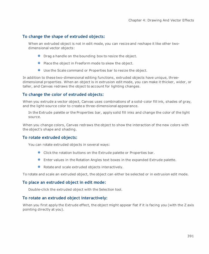
Chapter 4: Drawing And Vector Effects
To change the shape of extruded objects:
When an extruded object is not in edit mode, you can resize and reshape it like other two-dimensional vector objects:
Drag a handle on the bounding box to resize the object.
Place the object in Freeformmode to skew the object.
Use the Scale command or Properties bar to resize the object.
In addition to these two-dimensional editing functions, extruded objects have unique, three-dimensional properties. When an object is in extrusion edit mode, you can make it thicker, wider, ortaller, and Canvas redraws the object to account for lighting changes.
To change the color of extruded objects:
When you extrude a vector object, Canvas uses combinations of a solid-color fill ink, shades of gray,and the light-source color to create a three-dimensional appearance.
In the Extrude palette or the Properties bar, apply solid fill inks and change the color of the lightsource.
When you change colors, Canvas redraws the object to show the interaction of the new colors withthe object’s shape and shading.
To rotate extruded objects:
You can rotate extruded objects in several ways:
Click the rotation buttons on the Extrude palette or Properties bar.
Enter values in the Rotation Angles text boxes in the expanded Extrude palette.
Rotate and scale extruded objects interactively.
To rotate and scale an extruded object, the object can either be selected or in extrusion edit mode.
To place an extruded object in edit mode:
Double-click the extruded object with the Selection tool.
To rotate an extruded object interactively:
When you first apply the Extrude effect, the object might appear flat if it is facing you (with the Z axispointing directly at you).
391

Canvas 12 User Guide
1. Rotate an edge of the object toward you.
2. With the rotation pointer, drag a side in the direction you want to rotate the object.
As you drag, Canvas displays a circle to show the space in which the object can rotate.
3. Drag inside the circle to rotate the object in all three dimensions.
4. Drag outside the circle to rotate the object on the plane that is facing you.
You can also rotate an extruded object in two dimensions, like other vector objects, choosing Effects| Rotate or Freeform. The object can’t be in extrusion edit mode to use these commands. When youuse the Rotate and Freeform commands, Canvas does not reapply lighting effects as with three-dimensional rotation; i.e., the light source appears tomove with the object, instead of remaining inthe same place as the object rotates.
Colorizing objects
Use the Colorize command to tint vector objects with solid color fill or pen inks when you want to mixtwo colors, or shade one color with another. Doing this in the Presets palette can be complicated,since you have to create a custom color and set the correct values to approximate a two-colormixture. The Colorize command lets you simply select two colors and choose the percentage of each.
To colorize a vector object:
1. Select at least one vector object that has a solid color fill or pen ink. Colorize has no effect ongradient, hatch, texture, and symbol inks.
2. Choose Effects | Colorize.
3. In the Colorize dialog box, turn on the Fill and Stroke options to colorize both, or select theone ink you want to colorize.
4. In the pop-up color palettes, select the colors you want to add to the inks of the selectedobjects.
5. Use the sliders or enter a percentage in the text boxes to set the amount of color to mix withthe object’s color.
6. Turn on Preview to see the effect or click OK to colorize the object.
How colorization works
Canvas uses the specified percentages to determine the new color values for the selected object. Foreach color value (e.g., Red, Green, and Blue in the RGB color model), Canvas finds the difference
392

Chapter 4: Drawing And Vector Effects
between the tint and the original color. Then, Canvas multiplies the differences by the percentageyou specify, and adds these values to the original color values.
Colorization calculations
An object’s color has a red value of 40%. To tint 50% with a color that has a red value of 100%,Canvas calculates a new red value of 70%. The same calculations apply to the green and blue valuesfor an RGB color.
Fractalizing objects
Fractals aremathematical transformations that simulate the irregularities and patterns in naturalshapes, such as coastlines and mountain ranges. When you fractalize a vector object, its outlinebecomes jagged. You can use the Fractalize command to add a fractal effect to any vector objectexcept dimension objects and Smart Lines.
Vector objects Fractalized mountains
To fractalize an object:
1. Select at least one object and choose Effects | Fractalize.
2. Enter the Wiggle and Density values, and choose Curves or Polygon fractals.
3. Click Apply to preview the effect. Click OK to apply the effect and close the dialog box.
393
Canvas 12 User Guide
Fractalize options
Wiggle The amount a fractalized path can deviate from the original path. Enter anumber between 0 and 20; higher numbers increase the amount ofwiggle.
Density The smoothness of the fractalized path. Enter a number between 0 and5. Higher values increase the number of anchor points Canvas add to thepath. Lower densities result in sharper angles.
Curves or Polygon Polygon fractals can be jagged and use many anchor points, whilecurves fractals are smoother and require fewer additional anchor points.
Canvas fractalizes objects by adding several anchor points to an object’s path. High wiggleand density settings and polygon fractals can add numerous anchor points, which requiremorememory to print. Lower settings and curves fractals can help to conserve systemresources and eliminate problems you might have while printing.
Creating shadows for objects
The Shadow command lets you apply two types of offset (“drop”) shadows to selected objects. Usethe command to apply a shadow made of vector objects or an image. Canvas places the shadowdirectly behind the selected object in the stacking order.
You can edit shadow objects independently from the objects they are shadowing. Skew them tocreate oblique shadows and use filters to change their appearance. The original object and shadoware not grouped, so editing or moving one doesn’t affect the other.
394

Chapter 4: Drawing And Vector Effects
Vector and image type shadows withdifferent offsets
You can apply shadow effects to any vector or text object except dimension objects and Smart Lines.If you apply a vector shadow to a group of objects, Canvas groups the shadow objects and places theshadow behind the original group. If you apply a shadow to a paint object, Canvas creates a shadowof the paint object’s bounding box.
To create an offset shadow:
1. Select an object and choose Effects | Shadow.
2. In the Shadow dialog box, select options (see "Shadow options" on page 396).
3. Click Apply to see the effect. To accept the settings and close the dialog box, click OK.
395
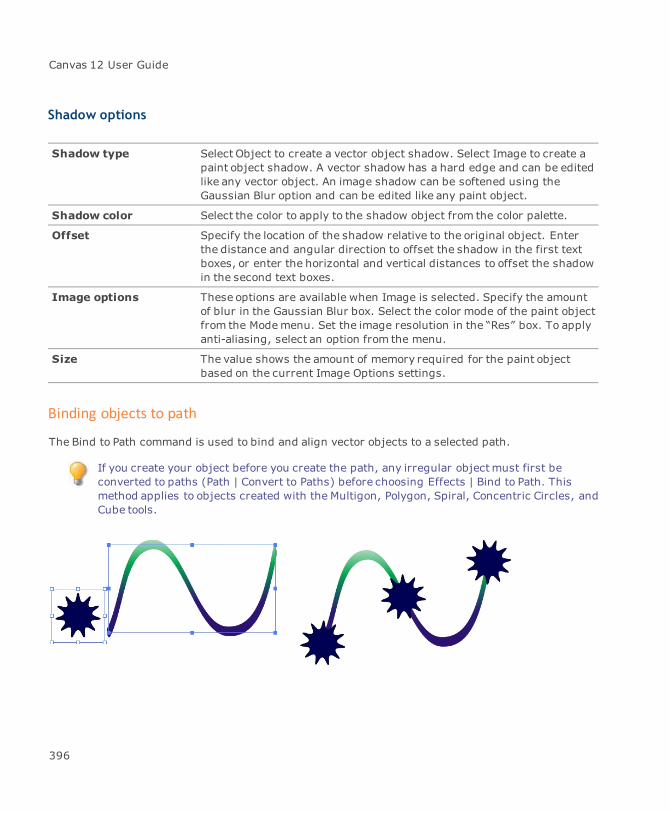
Canvas 12 User Guide
Shadow options
Shadow type Select Object to create a vector object shadow. Select Image to create apaint object shadow. A vector shadow has a hard edge and can be editedlike any vector object. An image shadow can be softened using theGaussian Blur option and can be edited like any paint object.
Shadow color Select the color to apply to the shadow object from the color palette.
Offset Specify the location of the shadow relative to the original object. Enterthe distance and angular direction to offset the shadow in the first textboxes, or enter the horizontal and vertical distances to offset the shadowin the second text boxes.
Image options These options are available when Image is selected. Specify the amountof blur in the Gaussian Blur box. Select the color mode of the paint objectfrom the Modemenu. Set the image resolution in the “Res” box. To applyanti-aliasing, select an option from the menu.
Size The value shows the amount of memory required for the paint objectbased on the current Image Options settings.
Binding objects to path
The Bind to Path command is used to bind and align vector objects to a selected path.
If you create your object before you create the path, any irregular objectmust first beconverted to paths (Path | Convert to Paths) before choosing Effects | Bind to Path. Thismethod applies to objects created with the Multigon, Polygon, Spiral, Concentric Circles, andCube tools.
396
Chapter 4: Drawing And Vector Effects
To bind an object to a path:
1. First create the path to which you are going to bind an object.
2. Then create the object and then select both.
3. Choose Effects | Bind to Path to open the Bind to Path dialog box.
Enter number of copies of objects.
Choose alignment of Top, Centers, or Bottom of path.
RotateObjects to Path. When checked, the object will rotate based on the direction of thepath.
4. Click the OK button to accept.
Dynamic objects & clipart
You can speed up many projects by taking advantage of reusable dynamic objects and ready-madeillustrations. This section describes how to use the Symbol Library.
Working with the Symbol Library palette
The Symbol Library palette comes stocked with a range of symbols you can use in your Canvasdocuments, or you can create your own symbols and add them to the Symbol Library. You can createsymbols from any vector, text, group, or paint object. If you change the symbol in the palette, all thecopies in the document will also change. For example, if you add a logo to the Symbol Library, and thelogo is updated, you can simply replace the logo in the Symbol Library, and all instances of the logo inyour document are updated.
To open the Symbol Library palette:
ChooseWindow | Palettes | Symbol Library.
Preview Size
You can preview the symbols in one of three sizes:
Small: 72 x 72 px
Medium: 108 x 108 px
Large: 144 x 144 px
397
Canvas 12 User Guide
To change the symbol preview size:
1. Click the Symbol Library palette menu button.
2. Select Toggle Preview Size.
Symbol Library options
To set the Symbol Library options:
1. Click the Symbol Library palette menu button.
2. Select Symbol Library Options.
Replace Options Select the options for replacing an element with a symbol:
Preserve source object size: Preserves the size of the object youare replacing with a symbol.Preserve aspect ratio of placed symbol: Preserves the aspectratio of the symbol, regardless of the size of the object you arereplacing.
Directory Paths of MySymbols
This section lists the directory paths of the folders in the Symbol Librarypalette, including the default path to the folder where your My Symbolsare located.
Add Path: Click this button to add a directory path to symbolslocated on your computer.Delete Path: Click this button to delete a selected directory path.
Symbol properties
Before you place a symbol from the Symbol Library palette, be sure to review the symbol properties inthe Properties bar.
X and Y Displays the X and Y coordinates where the symbol will be placed bydefault.
Reference point Displays the reference point for the symbol. This is the point on theselected object (or its bounding box) that position data is based on.Thereference point is also the fixed point used in an object’s transformation.
Width and Height Displays the height and width of the object.
398

Chapter 4: Drawing And Vector Effects
Original size Uses the symbol's original size.
Use original color Uses the symbol's original color. If you do not select this check box, thesymbol uses the default attributes from the Toolbox.
Preserve originalproportions
Uses the symbol's original proportions.
Create Click Create to place the selected symbol in the document.
Placing symbols
To place symbols:
1. Select the symbol in the Symbol Library palette.
2. Move the cursor into the layout area. The cursor changes to a place pointer.
3. Do one of the following:
To place the symbol at its original size, click in the layout areawhere you want to placethe upper left corner of the symbol.
To scale the symbol while you place it, drag the pointer to set the bounding box size.Canvas scales the symbol to fit the bounding box.
To constrain the proportions as you drag the point to set the bounding box, press Shift whilescaling.
Searching for and replacing symbols
To search for a symbol in the Symbol Library:
1. In the Symbol Library palette, type a search term in the search box.
2. Click the Search icon.
To search for a symbol in your document:
1. Right-click the symbol in the Symbol Library palette.
2. ChooseSearch and Select.
399

Canvas 12 User Guide
Canvas searches your document and selects every instance of the symbol.
To replace a symbol:
1. Select the symbol you want to replace in the document.
2. Select the replacement symbol in the Symbol Library palette.
3. Click Replace. The symbol in the document is replaced with the symbol selected in theSymbol Library palette.
Managing and organizing symbols and categories
To create a new category:
1. Select an existing category in the My Symbols section of the Symbol Library palette.
2. Right-click the category and select Create Category.
3. In the Add Category dialog box, type a name for the category, then click OK.
To rename a category:
1. Double-click a category in the My Symbols section of the Symbol Library palette.
2. Type a new name for the category.
To remove a category:
1. In the Symbol Library palette, click the Symbol Library palette menu button.
2. Select Symbol Library Options.
3. Select the category you want to remove.
4. Click Delete Path.
5. Click OK.
The path to the category is removed, so the category will no longer appear in the SymbolLibrary palette. However the folder and any symbols in it are not deleted. If you want to showthis category again, you can re-add the path to the category.If you no longer need thecategory or symbols, you can delete the folder and symbols in Windows Explorer.
To delete a symbol:
You can delete symbols from the My Symbols section of the Symbol Library.
400

Chapter 4: Drawing And Vector Effects
1. In the Symbol Library palette, select the symbol you want to delete.
2. Right-click and select Delete.
To select more than one symbol, hold down the Shift key while you click one or moresymbols.
To add a set of symbols to the Symbol Library:
If you have an existing set of symbols you want to add to the Symbol Library, you can simply add thedirectory path to the Symbol Library Options dialog box.
1. In the Symbol Library palette, click the Symbol Library palette menu button.
2. Select Symbol Library Options.
3. Click Add Path, browse for the folder containing your set of symbols, and then click OK.
4. Click OK to close the Symbol Library Options dialog box.
Canvas creates a new category corresponding to the folder name of the directory youselected.
To move a symbol to another category:
Drag the symbol from the Preview area to the name of the new category.
To add keywords:
1. In the Symbol Library palette, select the symbols you want to add keywords to.
2. Right-click one of the selected symbols, and select Add Keywords.
3. In the Add Keywords dialog box, type the keywords, then click OK.
To delete keywords:
1. In the Symbol Library palette, select the symbols you want to delete keywords from.
2. Right-click one of the selected symbols, and select Delete All Keywords.
3. Click Yes.
Creating new symbols
You can create your own symbols from a single vector object, a group of vector objects, or acomposite object. Text is converted to a path when an object is saved as a symbol.
401
Canvas 12 User Guide
Save your new symbols in the My Symbols folder so that they are available in the SymbolLibrary palette. If you prefer to create a new folder for your symbols, you can add the pathto the folder in the Symbol Library Options dialog box so that you can see the symbols in theSymbol Library palette.
To create a symbol:
1. Create a vector object, group of vector objects, or composite object in Canvas.
2. Select Object | Export As Symbol.
3. In the Browse For Folder dialog box, select a location for the symbol, and click OK.
4. In the Name Symbol dialog box, do one of the following:
If you want Canvas to automatically name the symbol for you, select the AutomaticNaming check box, and enter a Prefix and Keyword.
If you want to create a name for the symbol yourself, deselect the Automatic Namingcheck box, and type the name in the Name field.
5. Click OK.
If you want to add a new symbol to an existing category under My Symbols, you can simplydrag an object from your Canvas document to the category in the Symbol Library palette. Inthe Name Symbol dialog box, enter a name or use automatic naming, and enter anykeywords you want to add to the symbol.
Modifying preinstalled symbols
Canvas comes with hundreds of preinstalled symbols, many of which do not contain any fill. Becausethey don't contain any fill, if you try to apply a fill ink from the Toolbox, nothing happens. However, ifyou place the symbol in your document and ungroup the objects in the symbol, you can then add a fillink.
To modify a preinstalled symbol:
1. Select the symbol in the Symbol Library palette.
2. Click in your document to place the symbol.
3. In the Properties bar, click the Ungroup button.
4. Select one or more objects in the symbol that you want to edit.
402
Chapter 4: Drawing And Vector Effects
5. If the symbol contains objects stacked on top of each other, arranged the objects in anappropriate stacking order. Select an object, then choose Object | Arrange | Bring to Frontor Send to Back.
6. Tomodify the Pen Ink, select the objects you want to edit, then select a Pen Ink in theToolbox.
7. To modify the Fill Ink, select the objects you want to edit, then do one of the following:
Select a Fill Ink in the Toolbox.
Apply a fill ink with the Smart Vector Fill tool.
8. When you have finished editing the symbol objects, select all the objects, and click theGroup button in the Properties bar.
9. If you want to save the edited symbol, select Object | Export As Symbol, select a location forthe symbol, enter a name, and then click OK.
To place the modified symbol:
1. Select the symbol in the Symbol Library palette.
2. In the Properties bar, select the Use original color check box.
3. Click in your document to place the symbol.
Converting macro files to symbols
If you have used previous versions of Canvas (versions 3.5 to 11), you might have a set of legacyCanvas Macro files. You can convert these Macro files (.MCR) to the new Symbol file format (.CSY) sothat you can use them in the Symbol Library.
Save your new symbols in the My Symbols folder so that they are available in the Symbol Librarypalette. If you prefer to create a new folder for your symbols, you can add the path to the folder in theSymbol Library Options dialog box so that you can see the symbols in the Symbol Library palette.
To convert macro files to the new Symbol format:
1. ChooseObject | Convert Macro File.
2. In the Select a Macro File dialog box, select the file you want to convert, then click Open.
403
Canvas 12 User Guide
3. In the Convert Macro File dialog box, do one or more of the following:
If you want to add a prefix to the filenames of the symbols contained in the Macro file,enter the prefix.
If you want to add a keyword to the symbols, enter a keyword.
4. Click Export.
5. In the Browse For Folder dialog box, select a location for the symbols, and click OK.
A message is displayed when the file has been successfully converted.
6. Click OK.
404

Chapter 5: Painting And Image Editing
Canvas 12 User Guide
Painting & image-editing
Canvas provides a full palette of painting tools, including the digital equivalents of markers,airbrushes, and paintbrushes, plus tools for creating effects like neon and blends. The Painting toolspalette also provides tools to select, retouch, color-correct, and clone images (see "Tool palettes" onpage 23). This section explains how to use these painting tools, choose image modes, and convertobjects into images.
Paint objects and images
A paint object is a Canvas object that contains an image. Paint objects are always rectangular and thesame size as the images they contain. Images are pictures defined by pixels. A scanned photo, TIFF,or Photoshop (.PSD) file, and pictures you paint in Canvas are all images composed of pixels. Eachpixel in an image is a solid color. Pixels can also be semi-transparent or completely clear. You canadjust the color, opacity, and transparency of pixels by using painting tools and commands.
About paint objects and images in Canvas
You can perform common object operations, including move, copy, and duplicate, on paint objects.For details, see "Working with objects" on page 158. Or you can create images entirely in Canvas bymaking a new paint object that you can paint in, or creating an image from vector or text objects, asdescribed in this section.
You can import images into Canvas documents using the following methods:
Place an existing image in a document using the Place, Paste, or Import commands. See"Placing documents" on page 49 and "Importing and exporting images" on page 131.
Scan a photo using the Acquire command. See "Using scanners to acquire images" on page446.
Creating paint objects
You can make new paint objects containing blank images or convert objects into images by renderingthem. You can also scan images directly into a Canvas document (see "To open or place a file:" onpage 130 and "Importing images" on page 131 as well as "Using scanners to acquire images" onpage 446).
406

Chapter 5: Painting And Image Editing
Using the Paint Object Creator tool
The Paint Object Creator tool creates blank paint objects that you can use as a painting canvas. In theProperties bar, you can select settings for image mode, resolution, and background to be applied tonew paint objects you create with the Paint Object Creator tool or any painting tool (except the Croptool).
To select settings for new paint objects:
1. Select the Paint Object Creator tool from the Toolbox.
2. In the Properties bar, select the settings you want to use for paint objects.
Image mode Choose an image mode in themenu. The imagemode controls thenumber of colors that can be stored in an image (see "Imagemodes forCanvas paint objects" on page 435).
Resolution Enter a value from 1 to 2,540 pixels per inch and press Enter.
Background Choose the background color for the paint object: Opaque orTransparent.
To create a blank paint object:
1. Select the Paint Object Creator tool from the Toolbox.
2. Drag diagonally in the document to create a rectangular paint object.
A blank paint object appears in edit mode. You can now use the painting tools to paint on thepaint object.
3. When you have finished with the paint object, press Esc to exit edit mode.
Drag the Paint Object Creator toolto create a blank paint object
407
Canvas 12 User Guide
A paint object in edit mode,indicated by crop marks at eachcorner.
If the Auto Create check box is selected in the Properties bar for a painting tool, only thePaint Object Creator tool can be used to create blank paint objects. If the Auto Create checkbox is not selected, you can use any painting tool (except Crop) to create blank paintobjects.
To constrain the height and width of a paint object:
Do one of the following:
To constrain the height and width proportionally, press Shift as you drag with the PaintObject Creator tool.
To constrain the height and width symmetrically from the center, press Ctrl as you dragwith the Paint Object Creator tool.
To constrain the height and width proportionally and symmetrically, press Ctrl+Shift asyou drag with the Paint Object Creator tool.
Using the Create command
The Create command creates new paint objects using the mode, size, resolution, and transparencysettings that you specify. Use the Create command to create paint objects that are opaque ortransparent (see "Create Image options" on page 409).
To create a paint object:
1. With no objects selected, choose Image | Area | Create.
2. In the Create Image dialog box, set the image mode, type of background, background color(for an opaque image), size, and resolution of the image.
3. Click OK. The new paint object appears in the center of the view and is selected.
408
Chapter 5: Painting And Image Editing
Setting paint object dimensions
When you use the Create command, you can set the dimensions of a paint object using relative orabsolute values, depending on what you choose in the menus next to the Width and Height textboxes. If you choose pixels to set the dimensions of the paint object, the size of the object is relativeto its resolution; higher resolution makes pixels smaller, so the resulting object is smaller at thesamewidth and height values. If you choose inches, centimeters, picas, or points, enter absolutevalues for the paint object’s dimensions.
Create Image options
The Create Image dialog box has options for new images.
File Size The amount of memory required by the paint object, based onresolution, size, and mode. Black & White mode requires the leastmemory; CMYK Color requires the most.
Mode Choose an image mode. See "Image modes for Canvas paint objects" onpage 435.
Background Choose Transparent or Opaque. For Opaque, you can select a color fromthe color palette.
Transparent creates a clear background for the image. When you choosethis option, the color palette is not available.
Width and Height Enter the object’s width and height. In the adjacent menus, choosepixels or a unit of measurement.
Res Enter the image resolution. Choose pixels per inch or pixels percentimeter in the adjacent menu.
Auto Click Auto to calculate the resolution based on halftone screen frequencyand image quality.
To create a paint object with the Properties bar:
1. Select the Paint Object Creator tool.
2. In the Properties bar, enter the dimensions and resolution of the paint object.
3. Select the mode and background.
4. Specify the X/Y coordinates for the new paint object.
5. Click Create.
409
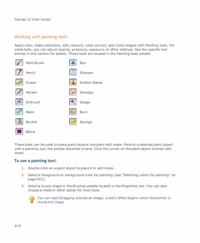
Canvas 12 User Guide
Working with painting tools
Apply color, make selections, edit, retouch, color-correct, and clone images with Painting tools. Forsome tools, you can adjust opacity, pressure, exposure, or other settings. See the specific toolentries in this section for details. These tools are located in the Painting tools palette.
Paint Brush Blur
Pencil Sharpen
Eraser Rubber Stamp
Marker Smudge
Airbrush Dodge
Neon Burn
Bucket Sponge
Blend
These tools can be used to place paint objects into paint edit mode. Point to a selected paint objectwith a painting tool, the pointer becomes a hand. Click the cursor on the paint object to enter editmode.
To use a painting tool:
1. Double-click on a paint object to place it in edit mode.
2. Select a foreground or background color for painting (see "Selecting colors for painting" onpage 423).
3. Select a brush shape in the Brushes palette located in the Properties bar. You can alsochoose a mode or other option for most tools.
You can start dragging outside an image; a tool’s effect begins when the pointer isinside the image.
410
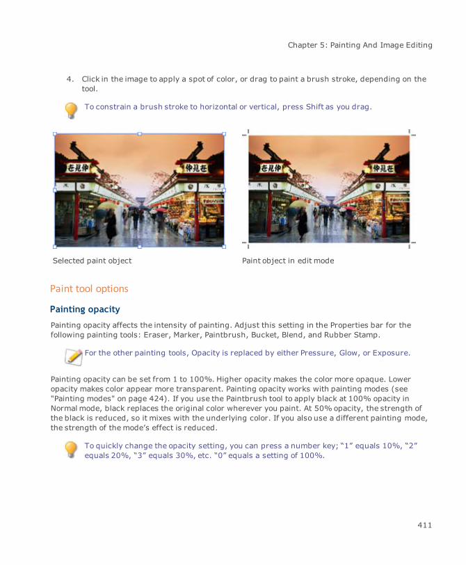
Chapter 5: Painting And Image Editing
4. Click in the image to apply a spot of color, or drag to paint a brush stroke, depending on thetool.
To constrain a brush stroke to horizontal or vertical, press Shift as you drag.
Selected paint object Paint object in edit mode
Paint tool options
Painting opacity
Painting opacity affects the intensity of painting. Adjust this setting in the Properties bar for thefollowing painting tools: Eraser, Marker, Paintbrush, Bucket, Blend, and Rubber Stamp.
For the other painting tools, Opacity is replaced by either Pressure, Glow, or Exposure.
Painting opacity can be set from 1 to 100%. Higher opacity makes the color more opaque. Loweropacity makes color appear more transparent. Painting opacity works with painting modes (see"Painting modes" on page 424). If you use the Paintbrush tool to apply black at 100% opacity inNormal mode, black replaces the original color wherever you paint. At 50%opacity, the strength ofthe black is reduced, so it mixes with the underlying color. If you also use a different painting mode,the strength of themode’s effect is reduced.
To quickly change the opacity setting, you can press a number key; “1” equals 10%, “2”equals 20%, “3” equals 30%, etc. “0” equals a setting of 100%.
411

Canvas 12 User Guide
To set painting opacity:
1. Select a painting tool that uses the opacity setting.
2. Move the Opacity slider or enter a percentage in the text box.
Canvas remembers each tool’s painting opacity setting; e.g., if you use the Blend tool at 30% opacityand then use the Paintbrush tool at 100% opacity, the setting changes back to 30%when you selectthe Blend tool again.
The Opacity slider in the Brushes palette affects subsequent brush strokes by the currentpainting tool only. It is not the same as the Opacity slider in the Toolbox and theTransparency palette, which are linked and control overall opacity of selected objects.
Fade settings
The following tools have Fade settings: Paintbrush, Airbrush, Blur, Dodge, Burn, Eraser, Marker,Sponge, Smudge, Sharpen, and Rubber Stamp.
Select the options you want to use in the Fade area. In the Fade within field, enter the distance inwhich Canvas will complete the fade.
To gradually diminish the brush size as you drag:
Select the Size check box.
To fade the color to transparent:
Select the Opacity check box. Depending on the selected tool, the check box may be labeled asPressure or Exposure.
Pressure Sensitive settings
If you are using a pressure-sensitive, plug-in device, such as a Wacom™ tablet, the Pressure Variesoptions are located within the Image/Multimedia managers in the Configuration Center.
To access the Pressure Varies options:
Double-click on the tool icon in the Toolbox to open the tool settings in the Configuration Center.You need to use a pressure-sensitive, plug-in device, such as a Wacom™ tablet. Use theseoptions tomake a pressure-sensitive stylus.
412

Chapter 5: Painting And Image Editing
Painting with the Paintbrush tool
The Paintbrush tool applies the foreground color. Apply a soft (anti-aliased) brush stroke bychoosing a soft-edged brush in the Properties bar or Brushes palette. Use the settings in theProperties bar to configure this tool.
Spraying soft strokes with the Airbrush tool
The Airbrush tool applies the foreground color with a very soft (anti-aliased) stroke. The Airbrushtool paints as long as you press themouse. The Pressure setting in the Properties bar and Brushespalette controls how fast the Airbrush applies color. Use the settings in the Properties bar toconfigure this tool.
Painting with the Marker tool
The Marker tool paints with the foreground color, applying a hard-edged stroke. Use the options inthe Properties bar to configure the Marker tool.
Painting individual pixels with the Pencil tool
Use the Pencil tool to apply the foreground color to a single pixel or create a one-pixel, freehand line.If the pixel already uses the foreground color, the Pencil applies the background color instead. Youcan use the Pencil tool for precise image editing at high magnifications (see "Fat Bits" on page 428).
To paint a straight line:
Shift-drag the Pencil to confine the line to 90° angles.
Painting two-toned “neon” strokes
Use the Neon tool to paint a neon-tube stroke, with the foreground color inside and the backgroundcolor outside. Use the Glow setting in the Properties bar and Brushes palette to adjust the color ratio.Painting modes are not available with the Neon tool.
Filling areas with color
Use the Bucket tool to pour color on an image. The Bucket applies the background color where youclick. You can adjust its tolerance so the color covers adjacent pixels of the same color only, oradjacent pixels of similar colors.
413

Canvas 12 User Guide
Tolerance
The Tolerance setting is located in the Properties bar.
To affect only identically-colored pixels:
Type 0 in the Tolerance text box.
To affect more pixels:
Type a larger number.
To soften the edge of the filled area:
Turn on Anti-Aliased.
Painting in the background color with the Eraser tool
Paint with the background color using the Eraser tool. If a paint object has a visibility mask, theEraser clears the pixels it touches, revealing a clear background. If the paint object does not have avisibility mask, the Eraser applies the background color.
Opacity and paint mode options are not available with the Eraser.
Painting with the Blend tool
Paint a blend of colors in an image with the Blend tool. The default behavior (Foreground ToBackground) creates a blend of the foreground and background colors. This tool is very useful forcreating blends from black to white in channels, to make selection masks that fade gradually from fullselection to no selection.
Linear blend Radial blend
Set the style and behavior using the settings in the Properties bar.
414
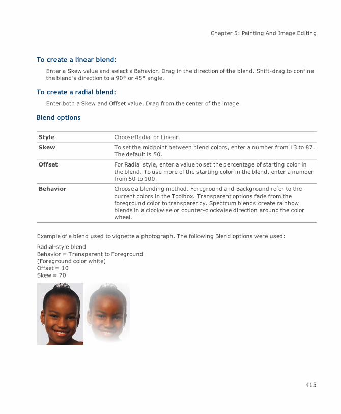
Chapter 5: Painting And Image Editing
To create a linear blend:
Enter a Skew value and select a Behavior. Drag in the direction of the blend. Shift-drag to confinethe blend’s direction to a 90° or 45° angle.
To create a radial blend:
Enter both a Skew and Offset value. Drag from the center of the image.
Blend options
Style ChooseRadial or Linear.
Skew To set the midpoint between blend colors, enter a number from 13 to 87.The default is 50.
Offset For Radial style, enter a value to set the percentage of starting color inthe blend. To use more of the starting color in the blend, enter a numberfrom 50 to 100.
Behavior Choose a blending method. Foreground and Background refer to thecurrent colors in the Toolbox. Transparent options fade from theforeground color to transparency. Spectrum blends create rainbowblends in a clockwise or counter-clockwise direction around the colorwheel.
Example of a blend used to vignette a photograph. The following Blend options were used:
Radial-style blendBehavior = Transparent to Foreground(Foreground color white)Offset = 10Skew = 70
415
Canvas 12 User Guide
Copying areas with the Rubber Stamp tool
Make a copy (“clone”) of an image area with the Rubber Stamp tool. This tool is very useful forretouching scanned photographs, removing lines and scratches, as well as hiding seams whencompositing images. Use the settings in the Properties bar to configure the Rubber Stamp tool.
Cloning styles
The effect of dragging the Rubber Stamp tool in an image depends on the option you choose in theStylemenu in the Properties bar.
Clone (aligned): The first time you drag the Rubber Stamp tool in the image after settingthe reference point, Canvas establishes a fixed direction and distance from the referencepoint to the pointer. The Rubber Stamp tool copies any area of the image that is this distanceand direction from the pointer.
Clone (non-aligned): Dragging the Rubber Stamp tool always begins copying the imagefrom the same reference point.
Impressionist: This option smears pixels to create an impressionistic effect. You don’t needto set a reference point to use this effect.
To use the Rubber Stamp tool:
Rubber Stamp pointer with Alt pressed
Rubber Stamp pointer without modifier key
1. Configure the tool using the settings in the Properties bar (see "Painting opacity" on page411, "Painting modes" on page 424, and "Cloning styles" on page 416).
2. Alt-click in the image to set the reference point for sampling an image area.
3. Drag in the image to paint a copy of the sampled area around the reference point.
416

Chapter 5: Painting And Image Editing
Clone (aligned option) Clone (Non-aligned option)
Smudging colors
With the Smudge tool, pull color from one area of an image and drag it into adjacent areas. Use thesettings in the Properties bar to configure the tool.
To use the Smudge tool:
1. Configure the tool using the settings in the Properties bar.
Select a brush size and shape from the Brushes palette (see "Selecting brushes andpainting options" on page 420).
Adjust the Pressure setting. A setting of 1 affects the image slightly; 85 drags the colorthrough many pixels.
2. Drag the Smudge tool in the image area you want to edit.
To smudge the foreground color into the image:
Choose the Finger Painting option.
417

Canvas 12 User Guide
Lightening (‘dodge’) areas
The Dodge tool lightens specific areas of an image. Use the settings in the Properties bar to configurethe tool.
To use the Dodge tool:
1. Configure the tool using the settings in the Properties bar.
Select a brush size and shape from the Brushes palette (see "Selecting brushes andpainting options" on page 420).
Adjust the Exposure setting. Increasing the Exposure increases the lightening effect ofthe tool. Decreasing the setting decreases the effect.
ChooseShadows, Midtones, or Highlights from the Mode menu. The Dodge tool lightenspixels that fall within the selected range only.
2. Drag the Dodge tool in the image area you want to edit.
Darkening (‘burn’) areas
Darken specific areas of an image by dragging the Burn tool over the pixels you want to darken. Thetool’s effect can be controlled by your selection of brush and adjustment of the tool’s Fade setting.Use the settings in the Properties bar to configure the tool.
To use the Burn tool:
1. Configure the tool using the settings in the Properties bar.
Select a brush size and shape from the Brushes palette (see "Selecting brushes andpainting options" on page 420).
Adjust the Exposure setting. Increasing the Exposure increases the darkening effect ofthe tool. Decreasing the setting decreases the effect.
ChooseShadows, Midtones, or Highlights from the Mode menu. The Burn tool darkenspixels that fall within the selected range only.
2. Drag the Burn tool in the image area you want to edit.
Blurring areas
Soften specific areas in an image with the Blur tool. The Blur tool decreases the contrast betweenpixels the tool drags over. Use the settings in the Properties bar to configure the tool.
418

Chapter 5: Painting And Image Editing
Select the Blur tool and click a paint object to put the image in edit mode, if necessary.
To use the Blur tool:
1. Configure the tool using the settings in the Properties bar.
Select a brush size and shape from the Brushes palette (see "Selecting brushes andpainting options" on page 420).
Adjust the Pressure setting. A setting of 1 affects the image slightly; 85 softens theimage greatly.
ChooseNormal, Darken, or Lighten from the Mode menu. The Blur tool darkens pixels thatfall within the selected range only.
2. Drag the Blur tool in the image area you want to edit. Canvas applies the effect to pixelstouched by the tool.
Sharpening areas
Increase the contrast between specific pixels in an image with the Sharpen tool. Use the settings inthe Properties bar to configure the tool.
To use the Sharpen tool:
1. Configure the tool using the settings in the Properties bar.
Select a brush size and shape from the Brushes palette (see "Selecting brushes andpainting options" on page 420).
Adjust the Pressure setting. A setting of 1 affects the image slightly; 85 dramaticallysharpens the image.
ChooseNormal, Darken, or Lighten from the Mode menu.
2. Drag the Sharpen tool in the image area you want to edit. Canvas applies the sharpeningeffect to pixels touched by the tool.
Saturating and desaturating colors
With the Sponge tool, add or remove gray content from specific areas of an image. Use the settings inthe Properties bar to configure the tool.
419
Canvas 12 User Guide
To use the Sponge tool:
1. Configure the tool using the settings in the Properties bar.
Select a brush size and shape from the Brushes palette (see "Selecting brushes andpainting options" on page 420).
Adjust the Pressure setting. Increase the pressure to increase the effect.
ChooseSaturate or Desaturate in the Mode menu. Saturate removes gray; desaturateincreases the amount of gray.
2. Drag the Sponge tool over the image area you want to edit.
Selecting brushes and painting options
The Properties bar contains the Brush icon as well as other options for painting and image editing.The Opacity slider lets you adjust opacity for painting. The Modemenu lets you choose paintingmodes to control color application and target tonal ranges. Open the Brushes palette to select presetbrushes and create new brushes.
The Brushes palette contains the same painting options as the Properties bar; e.g., theOpacity slider, painting modes, etc.
The Brush icon appears in the Properties bar when one of the following Painting tools isselected: Eraser, Paintbrush, Marker, Airbrush, Neon, Rubber Stamp, Smudge, Blur,Sharpen, Dodge, Burn, Sponge.
Brush icon
Use the Brush icon to adjust current brush settings or to open the Brush palette and select anotherbrush.
To modify brush settings:
You must select a Painting tool, such as the Paintbrush or Pencil tool, so the Brush icon is active inthe Properties bar. You can edit any brush shape. For brush shapes created from selections, you canchange only the spacing.
420

Chapter 5: Painting And Image Editing
1. Click on the Brush icon in the Properties bar to open the Brush Options dialog box.
2. Make any adjustments to the current brush’s settings (see "New brush options" on page422). You can also add the brush to the Brushes palette by clicking the button located in theupper right corner.
You do not have to add the brush to the Brushes palette to be able to use it; however, ifyou plan on using a brush more than once, we recommend that you add it to thepalette.
3. Begin painting with the modified brush.
To select brushes from the Brushes palette:
1. Click on the arrow that is next to the Brush icon and the Brushes palette pops out.
You can drag the Brushes palette off the Properties bar. The Brushes palette hascommands for creating brushes, saving brushes to a file, loading brush files, anddeleting unused brushes.
2. Click on a brush shape and begin painting.
While painting, use the context menu to change brushes and select painting options ( see "To accessthe context menu:" on page 427).
Brushes palette menu
Use the Brushes palette menu to create new brushes, save brushes in files, modify existing brushes,and delete brushes.
You can add custom brushes to the list of preset brushes in the palette. When you exit Canvas, itstores the brush presets. The same set of brushes are available whether you work with newdocuments, documents you created, or documents created by another Canvas user.
To create a new brush:
1. Open the Brushes palette menu and choose New Brush.
2. In the New Brush dialog box, adjust the settings for the brush (see "New brush options" onpage 422).
3. Click OK after entering the settings you want. The new brush shape appears in the Brushespalette.
421
Canvas 12 User Guide
New brush options
Create brush shapes by specifying diameter, hardness, spacing, roundness, and angle. These sameoptions are available in the Brush Options dialog box.
Diameter Enter the diameter in pixels of the new brush.
Hardness Enter a percentage to tell Canvas how much of the brush shape is solid.
Spacing This percentage sets the amount of brush overlap when you drag apainting tool. Turn off Spacing tomake the brush velocity-sensitive, so itskips pixels when dragged fast.
Roundness Enter 1 to 100. To create a circle, enter 100.
Angle Enter a number to rotate the brush shape.
Brush tip Drag to change Roundness.
Drag to change the Angle.
Preview Preview of the brush shape.
To define a brush shape with a selection:
You can make a new brush shape from a selection in an image. This lets you create non-ellipticalbrush shapes.
1. Select all or part of an image (see "Selecting pixels in images" on page 483).
2. ChooseDefine Brush in themenu. The selection becomes a brush in the Brushes palette.Canvas uses the shape and lightness values of the selection to define the brush. Brushshapes do not contain color.
To delete brushes from the palette:
You can permanently remove brush shapes from the Brushes palette. If you think you might want touse the brush shape again, you should first store it in a brushes file so at a later time you can load itback into the palette (see "To save brushes in a file:" on page 422).
1. Select the brush you want to delete.
2. ChooseDelete Brush in themenu. You can also Alt-click a brush in the palette to delete it.
To save brushes in a file:
You can save brushes in a file. Saving brushes to disk lets you customize the Brushes palette forparticular projects or exchange brushes with other Canvas users. The file format that Canvas uses to
422
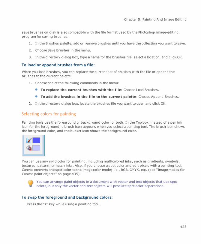
Chapter 5: Painting And Image Editing
save brushes on disk is also compatible with the file format used by the Photoshop image-editingprogram for saving brushes.
1. In the Brushes palette, add or remove brushes until you have the collection you want to save.
2. ChooseSave Brushes in themenu.
3. In the directory dialog box, type a name for the brushes file, select a location, and click OK.
To load or append brushes from a file:
When you load brushes, you can replace the current set of brushes with the file or append thebrushes to the current palette.
1. Choose one of the following commands in themenu:
To replace the current brushes with the file: Choose Load Brushes.
To add the brushes in the file to the current palette: Choose Append Brushes.
2. In the directory dialog box, locate the brushes file you want to open and click OK.
Selecting colors for painting
Painting tools use the foreground or background color, or both. In the Toolbox, instead of a pen inkicon for the foreground, a brush icon appears when you select a painting tool. The brush icon showsthe foreground color, and the bucket icon shows the background color.
You can use any solid color for painting, including multicolored inks, such as gradients, symbols,textures, pattern, or hatch inks. Also, if you choose a spot color and edit pixels with a painting tool,Canvas converts the spot color to the image color mode; i.e., RGB, CMYK, etc. (see "Imagemodes forCanvas paint objects" on page 435).
You can arrange paint objects in a document with vector and text objects that use spotcolors, but only the vector and text objects will produce spot color separations.
To swap the foreground and background colors:
Press the “X” key while using a painting tool.
423

Canvas 12 User Guide
To set the foreground color to black and background color to white:
Press the “C” key.
To select a color for painting:
1. Click the foreground or background color icon in the Toolbox.
2. In the Presets palette, on the Ink tab, click on an ink type and select a color.
You can also create new colors by using the various Inks managers located in the Attributespalette (see "Creating color inks" on page 231).
Picking colors with the Color Dropper tool
Use the Color Dropper tool to pick up color from an image or object. The color you select becomes thecurrent background or foreground color that you can use for painting and drawing (see "Using theColor Dropper" on page 254).
While in image edit mode, select the Color Dropper by pressing Alt; however, you won’t be able topick the background color.
To select the background color from a paint object:
1. Select the Color Dropper tool from the Toolbox.
2. Click a color in the paint object or image.
The background color changes in the Toolbox.
To select the foreground color from a paint object:
1. Select the Color Dropper tool from the Toolbox.
2. Right-click a color in the paint object or image.
The foreground color changes in the Toolbox.
Painting modes
Use various painting modes when you paint and edit images. Painting modes can create specialeffects and let you control color mixing and the tonal range affected by painting.
424

Chapter 5: Painting And Image Editing
The Mode menu is in the Properties bar and Brushes palette when you use the following tools:Marker, Paintbrush, Airbrush, Bucket, Blend, Blur, Sharpen, and Rubber Stamp. Painting modes thatare available for most painting tools are listed here.
To choose a painting mode:
1. Select a painting tool.
2. Open the Modemenu and select a mode.
Not all modes are available for all painting tools.
Mode Function
Normal The default painting mode applies color to all pixels uniformly. When thepainting opacity is 100%, the applied color replaces the original color. Ifyou paint in a Black & White or Indexed image, Normal mode is labeledThreshold.
Dissolve This mode applies color with a random diffused pattern within the brushshape. The effect is similar to drawing with chalk. The diffused effect isstronger when the painting opacity is less than 100%.
Multiply Darkens all pixels by multiplying the value of the applied color and theunderlying color. Painting with darker colors intensifies the effect.Painting with black results in black; painting with white does not affectthe original color. When you apply a color with multiple strokes in thesame area, the strokes become darker, similar to the effect of makingmultiple strokes on paper with an ink marker.
Screen The Screen mode is the opposite of Multiply mode. Screen mode lightensall pixels by multiplying the inverse values of the applied color and theunderlying color. Painting with lighter colors intensifies the effect.Painting with black does not affect the original image; painting withwhite results in white.
Overlay Applies color without destroying the underlying shadows and highlights.Overlay mode blends the applied color with the underlying color; theamount of blending depends on the lightness of the underlying color.
Soft Light Lightens or darkens underlying colors depending on the lightness valueof the applied color. If the lightness of the applied color is less than 50%gray, painting lightens the image. If the lightness of the applied color isgreater than 50% gray, painting darkens the image. Painting with whiteor black has the most intense effect, but does not completely replace theunderlying color.
425
Canvas 12 User Guide
Mode Function
Hard Light Paints in Multiply or Screen mode, depending on the applied color’slightness value. This mode is similar to Soft Light. However, paintingwith black produces black; painting with white produces white.
Darken Compares the underlying color and the applied color, and the result iswhichever color is darker. In other words, pixels in the image will bepainted if the paint color is darker, while pixels that are darker than thepaint color will remain unpainted.
Lighten The Lighten mode is the opposite of Darken mode. Lighten compares theunderlying color and the applied color, and the result is whichever coloris lighter. In other words, pixels in the image will be painted if the paintcolor is lighter; pixels that are lighter than the paint color will remainunpainted.
Difference Compares the brightness of the original and applied colors, subtractsthe brightness value of the darker pixel from the lighter one, and appliesthat value to the original image.
Hue Applies the hue of the paint color without changing the brightness andsaturation of the underlying image.
Saturation Changes the saturation of the area painted to match the saturation of theapplied color, without changing the hue or luminance values. Applyinggray does not affect the original image.
Color Changes the hue and saturation of the painted area to the hue andsaturation of the applied color, without affecting the shadow, highlights,or midtones of the original image.
Luminosity Changes the lightness of the underlying color to the lightness of theapplied color, without affecting the hue or saturation of the image.
Painting context menu
When working with a painting tool, use the context menu to gain quick access to common commands.The commands that are available vary, depending on the selected painting tool and whether there is aselection in the image.
The context menu contains some common commands that are available from the Menu bar.
426
Chapter 5: Painting And Image Editing
To access the context menu:
1. Select a paint object.
2. Right-click the selected paint object.
3. Choose a command when the menu opens. Canvas applies the command and hides the menu.
Context menu options
The following commands are available in the painting context menu:
Command Use
Next Brush Selects the brush shape in the Brushes palette to the right of the currentbrush.
Previous Brush Selects the brush shape in the Brushes palette to the left of the currentbrush.
First Brush Selects the brush at the upper-left of the palette.
Last Brush Selects the brush at the lower-right of the palette.
Standard Pointer Displays the icon of the selected painting tool, which is the defaultpointer (see "Pointer display" on page 427).
Precise Pointer Changes the pointer to a crosshair. The intersection of the crosshair isthe center of the current brush (see "Pointer display" on page 427).
Brush Size Pointer Changes the pointer to an outline of the current brush (see "Pointerdisplay" on page 427).
Show/Hide Fat Bits Displays/hides pixels as individual tiles in a grid at high magnifications(see "Fat Bits" on page 428).
Show/HideTransparency Preview
Displays or hides transparent sections of an imagewhile in edit mode.
Pointer display
The default pointer for painting is a symbol of the selected painting tool. Change the pointer to acrosshair or the current brush size. All painting tools use the pointer you select, not just the currentpainting tool. To change the pointer, choose an option in the context menu.
Changing the pointer using the context menu is the same as changing the pointer in thePainting manager located in the Configuration Center.
427

Canvas 12 User Guide
Fat Bits
When you choose Show Fat Bits, the resolution and magnification affect the display. Fat Bits arevisible when the magnification-to-resolution ratio is about eight to one; e.g., if the image resolution is72 ppi, fat bits appear at 600% magnification and higher. If the image resolution is 144 ppi, fat bitsappear at 1,200%magnification.
To show fat bits:
Press the Plus key or choose Show Fat Bits in the context menu to display pixels as individual tilesin a grid.
To hide fat bits:
Press the Plus key or choose Hide Fat Bits in the context menu to display pixels without the grid ofindividual tiles.
Adding visibility masks to images
In a paint object that has a visibility mask, you can erase or delete pixels to reveal a clearbackground; e.g., you can erase at the edge of an image to create faded or torn edges. You candelete or move selections to create transparent areas. If a paint object does not have a visibility mask,areas where you drag the Eraser tool and selections you delete or move, become filled with thecurrent background color and are opaque, not transparent.
When you create paint objects with painting tools or the Render or Create commands, you can selectan option to include visibility masks.
White areas of the fish imageerased to a clear background
428

Chapter 5: Painting And Image Editing
To add a visibility mask:
1. Select a paint object that does not have a visibility mask.
2. Choose Image | Add Visibility Mask. This command is not available if a Duotone, Indexed, orMultichannel image is selected.
Adding a visibility mask does not change the appearance of a paint object; e.g., white pixels do notbecome transparent. When a paint object has a visibility mask, you can select Preserve Visibility inthe Channels palette. When this option is selected, Canvas protects clear areas from the effects ofpainting and image editing.
To create a transparent background:
1. Select the image object.
2. Click the fill ink icon in the Toolbox.
3. Select null ink. A visibility mask is applied to the object, and the white pixels becometransparent.
Paint object backgrounds
You can create a paint object in which the image “background” is transparent or opaque.
An opaque paint object contains opaque pixels. If the pixels are white and the paint object is on awhite background, you won’t notice that the image is opaque. Still, the rectangular paint object willblock objects behind it.
A transparent paint object can have a clear background that does not block other objects.
Painting in an opaque image is like painting on a wall. Painting in a transparent image is like paintingon a window.
429
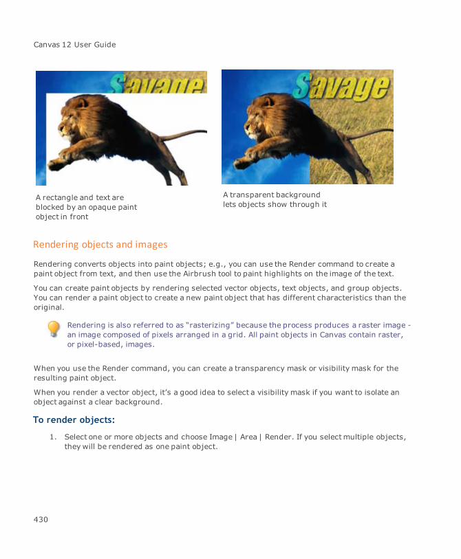
Canvas 12 User Guide
A rectangle and text areblocked by an opaque paintobject in front
A transparent backgroundlets objects show through it
Rendering objects and images
Rendering converts objects into paint objects; e.g., you can use the Render command to create apaint object from text, and then use the Airbrush tool to paint highlights on the image of the text.
You can create paint objects by rendering selected vector objects, text objects, and group objects.You can render a paint object to create a new paint object that has different characteristics than theoriginal.
Rendering is also referred to as “rasterizing” because the process produces a raster image -an image composed of pixels arranged in a grid. All paint objects in Canvas contain raster,or pixel-based, images.
When you use the Render command, you can create a transparency mask or visibility mask for theresulting paint object.
When you render a vector object, it’s a good idea to select a visibility mask if you want to isolate anobject against a clear background.
To render objects:
1. Select one or more objects and choose Image | Area | Render. If you selectmultiple objects,they will be rendered as one paint object.
430
Chapter 5: Painting And Image Editing
The Render Image dialog box lets you specify resolution and other settings for the resultingpaint object.
2. Click OK to render the selection.
Canvas creates a paint object containing an image of the original objects. The paint object appears infront. The Render command does not change the original selected objects.
To see the original objects:
Drag the paint object away.
Pasting into images
You can render objects by copying them to the Clipboard and then pasting them into paint objects inedit mode. When an image is in edit mode and you paste into it, the Clipboard content is renderedand appears as a selection in the image.
Anti-aliasing blurs edges while rendering tomake the edges of text characters and vectorobjects appear smoother in the resulting image.
If you select the “Anti-aliased Clipboard” option in the Configuration Center, Canvas anti-aliasesvector and text objects that you paste into paint objects (see "Setting preferences" on page 97).
Rendering exported files
If necessary, Canvas renders selected objects or an entire document when you use the Save Ascommand to export to a raster file format; e.g., if you select vector objects, and then save in GIFformat, Canvas renders the selected objects because GIF files store raster images.
When Canvas is saving a file, some options might not be available in the Render Image dialog boxbecause the file format doesn’t support them.
Render Image settings
Specify imagemode, resolution, and other settings in the Render Image dialog box.
Dimensions Displays the width and height of the paint object Canvas will create.
Choose the measurement for the Width and Height values in theDimension area; inches, centimeters (cm), points, or picas.
Mode Choose the color mode for the resulting image: Black & White,Grayscale, Indexed Color, RGB Color, CMYK Color, or LAB Color.
431
Canvas 12 User Guide
Width and Height Enter the pixel dimensions for the paint object. When you change avalue, Canvas adjusts the others tomaintain the size and proportions ofthe original objects.
Res Choose pixels per inch or pixels per centimeter in the pop-up menu. Thevalue shown after “Size” is the amount of data in the image, based on themode, resolution, and dimensions.
Anti-Alias Blurs edges while rendering to make the edges of text characters andvector objects appear smoother in the resulting image. Choose Fine,Medium, or Coarse in the pop-up menu.
Coarse uses 16 shades for anti-aliasing and is the fastest option.Mediumuses 64 shades for anti-aliasing. Fine uses 256 shades for anti-aliasing. Fine produces the softest edges and is the slowest option.
Mask Select this option if you want the resulting paint object to have a visibilitymask or a channel mask. Then choose the type of mask.
Transparency creates a channel mask. The channel mask is based on thesilhouette of the rendered objects. In other words, if there are spacesbetween the objects, the channel mask will create transparent spaces.
Visibility creates a visibility mask in the paint object. The result is a clearbackground in areas not covered by objects.
If you do not select Mask, areas not filled by rendered objects within thepaint object’s bounding rectangle will be white and opaque. If you selectMask and either Transparency or Visibility, areas that are not filled byrendered objects will be transparent.
Rendering with the Camera tool
You can use the Camera tool to create a paint object from any area in a document. The Camera toolrenders the area you select. You can set the resolution, color mode, and other options for therendered image. Using the Camera tool is like taking a snapshot of the screen. You simply use theCamera tool to select a rectangular area for rendering. You can include all types of objects and partsof objects in the rendering, without selecting the objects first.
The Camera tool is useful whenever you need to convert objects to an image, such as for creatingWeb graphics. The Camera tool functions like the Image | Area | Render command. The Camera toollets you control the exact area to be rendered, while the Render command renders a rectangular areathat includes all selected objects.
432
Chapter 5: Painting And Image Editing
To render with the Camera tool:
1. Select the Camera tool.
2. Drag to draw a rectangle around the area you want to render. View the dimensions andcoordinates of the rectangle in the Status bar. A bounding box with handles appears aroundthe area you selected.
3. Adjust the box to select exactly the area you want to render by using the controls in theProperties bar or manually changing the shape and size with the handles.
4. Enter values in the fields to change the position and size of the bounding box. Select aresolution or render at screen resolution. Drag the handles to manually reposition or resizethe bounding box.
5. Click the Accept button or click inside the area.
6. In the Render Image dialog box, select the options you want to use, and then click OK torender the selected area. After you click OK in the Render Image dialog box, a paint objectcontaining the rendered image appear on top of the area you selected.
Using vector and text tools in paint objects
After placing a paint object in edit mode, use vector tools and the Text tool to add shapes and type toan image.
When you draw or type text within a paint object in edit mode, Canvas rasterizes the objectsaccording to the image mode and resolution of the paint object, and makes a floating selection in theimage.
When you typewithin a paint object in edit mode, you can modify the font, size, and style of the typebeforeCanvas rasterizes it (see "To set type within images:" on page 434).
To set anti-aliasing for objects placed in images:
You can set a preference so Canvas softens the edges of objects you draw in an image or paste intoan image from the Clipboard (see "Setting preferences" on page 97).
433

Canvas 12 User Guide
1. Choose File | Configuration Center and select the Painting manager in the General settings.
2. Set the preferences you want to apply to objects placed in images and click OK.
To soften selections pasted from the Clipboard: Select “Anti-Aliased Clipboard.”
To soften objects or type created in paint objects in edit mode: Select “Anti-Aliased Canvas Objects.”
To draw objects within images:
Use any of the drawing tools in a paint object in edit mode to “paint” shapes. When you finishdrawing the shape, Canvas rasterizes it, based on its shape and colors.
1. Place the paint object in edit mode, if necessary, and select a drawing tool.
2. Select ink and stroke settings (see "Inks: colors & patterns" on page 223 and "Strokes:outline effects" on page 257).
3. Draw in the paint object with the selected tool (see "Drawing basics" on page 286). Theobject you draw becomes a floating selection and you can change its opacity, set the mode,or apply filters (see "Changing the opacity of floating selections" on page 496 and "Imagefilters & effects" on page 515).
4. Press Esc twice when you finish editing the selection tomake the selection part of the image.
5. Press Esc once more to exit edit mode and select the image.
To set type within images:
Type text in a paint object in edit mode and then modify the attributes before Canvas converts thetype to a floating selection.
Use the Text menu, Type palette, or Properties bar to set typographic attributes.
1. Place the paint object in edit mode, if necessary, and select the Text tool.
2. Click the I-beam pointer in the image and type the text, which appears in a white box.
3. Press Esc tomake the text a floating selection. You can change the opacity, set the mode,and apply filters to the selection (see "Changing the opacity of floating selections" on page496 and "Image filters & effects" on page 515).
4. Press Esc twice tomake the type selection part of the image.
5. Press Esc again to exit edit mode and select the image.
434
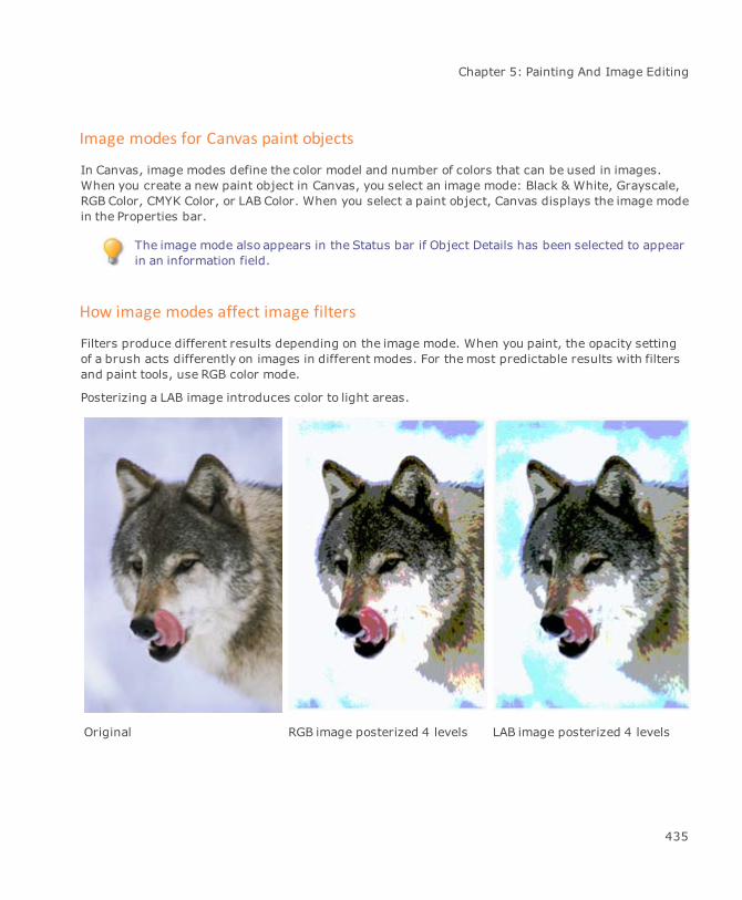
Chapter 5: Painting And Image Editing
Image modes for Canvas paint objects
In Canvas, image modes define the color model and number of colors that can be used in images.When you create a new paint object in Canvas, you select an image mode: Black & White, Grayscale,RGB Color, CMYK Color, or LAB Color. When you select a paint object, Canvas displays the image modein the Properties bar.
The image mode also appears in the Status bar if Object Details has been selected to appearin an information field.
How image modes affect image filters
Filters produce different results depending on the image mode. When you paint, the opacity settingof a brush acts differently on images in different modes. For themost predictable results with filtersand paint tools, use RGB color mode.
Posterizing a LAB image introduces color to light areas.
Original RGB image posterized 4 levels LAB image posterized 4 levels
435
Canvas 12 User Guide
How Canvas assigns image modes
When you import an image from another source either by opening, placing, or pasting an image file,Canvas assigns an image mode based on the number of colors and the color model used in the image.
The following table shows the image modes that Canvas assigns when you import images in somecommon image formats.
Imported format Assigned image mode
TIFF RGB Color, CMYK Color, or Grayscale
BMP 256-color image: Indexed24-bit image: RGB Color
MacPaint Black & White
Photoshop Same as original image mode
Changing image modes
You might want to change modes so you can use certain features, or reduce memory requirements;e.g., you might want to convert an Indexed image to RGB to apply image filters. You might want toconvert an RGB image to Grayscale mode to save memory when a document is printed without color.
You can access the Image Mode menu on the Properties bar or by choosing Image | Mode.
To change image modes:
1. Select one or more paint objects.
2. Select the image mode from the ImageMode menu in the Properties bar.
Somemodes are available only if the object’s current mode is compatible; e.g., Black & White modeand Duotone mode are available only when Grayscale paint objects are selected.
If themode you choose does not support an image’s full color range, a message asks you to confirmthe change. Click OK to proceed.
If you choose Duotone mode or Indexed mode, select options in a dialog box and then click OK tocomplete the conversion (see "Duotone imagemode" on page 442 and "Indexed image mode" onpage 438).
436
Chapter 5: Painting And Image Editing
Black & White image mode
Black & White image mode is used for scanned line art and black-and-white (“bitmap”) images,which contain only black and white pixels. Images in Black & Whitemode require the least amount ofmemory and disk space.
To convert to Black & White mode:
Grayscale mode images and Multichannel mode images are the only images you can directly convertto Black & White mode. If an image is not Grayscale, convert it to Grayscale mode first if you want toconvert it to Black & White mode.
1. Select the paint objects and use the Image Mode menu on the Properties bar or choose Image| Mode | Black & White. The Select Halftone Method dialog box lets you choose a conversionoption.
2. Select one of the following:
Pattern Dither: Canvas “screens” the image, rendering its tones as patterns of tinydots, using a fixed pattern similar to a traditional halftone screen
Diffusion Dither: Canvas “screens” the image, rendering its tones as patterns of tinydots, using a process that creates a random pattern effect.
Threshold: Canvas converts the image to a high-contrast, black-and-white image. Pixelsof lightness values from 0 to 128 become black, and pixels of lightness values from 129to 255 become white.
3. Click OK.
When you paste a selection into a Black & White image, Canvas uses diffusion dither on theselection.
Grayscale image mode
Grayscale mode is appropriate for images scanned from black & white photographs or when theimagewill never be printed in color. In Grayscale mode, pixels use 256 brightness levels to representa range of shades from pure black to pure white. Grayscale uses 8 bits per pixel and requires lessmemory than most color modes.
If you convert a color image to Grayscale mode, Canvas discards all color information.
437

Canvas 12 User Guide
Indexed image mode
Indexed color mode uses a palette of 256 colors for images. Since this mode stores fewer colors, itrequires significantly less memory than RGB and CMYK color modes, both of which support millionsof colors. Smaller memory requirements make Indexed mode especially useful for images used onWeb pages.
An Indexed image includes a color table, or palette, of colors used in the image. When you convert anexisting image to Indexed mode, you can specify the number of colors from the image to include inthe color table.
Most image filters, effects, and opacity controls aren’t available to be applied to Indexed images,except the Offset and De-Interlace filters, as well as some third-party plug-in filters.
To convert an existing image to Indexed mode:
1. Select the paint objects and choose Indexed from the ImageMode menu.
2. In the Indexed Color dialog box, choose an option in the Indexed Color dialog box for thecolor table.
Depending on which method you select, the Colors area in the dialog box displaysinformation about how the color table is computed.
Exact Creates a color table from the colors in the image, if the imagecontains 256 colors or less; otherwise, this option isn’t available.The Colors area displays the number of colors in the selectedimage.
Uniform/System
Creates a color table based on the operating system’s palette of 256colors (System), or a subset of these colors (Uniform). The Colorsarea displays the number of colors in the operating system’spalette; if you choose Uniform, a pop-up menu that lets you select8, 27, 64, 125, 216, or 256 colors appears.
Adaptive Creates a color table from the most frequently used colors in theimage. The Colors area displays a text box that lets you enter anumber of colors from 2 to 256
Custom Lets you create a color table, load, and save color table files. TheColors area displays “Custom colors”.
Previous Applies the last color table used in the Indexed Color dialog boxduring the current Canvas session. The Colors area displays thenumber of colors in the last color table created by the Indexed Colordialog box during the current Canvas session.
438

Chapter 5: Painting And Image Editing
3. Choose a color-distribution option in the Dither area:
None Changes colors to their closest equivalent in the selected color tablewithout dithering.
Pattern Approximates colors not in the palette by arranging palette color ingeometric patterns (available for Uniform/System method only).
Diffusion Approximates non-palette colors by randomly dithering availablecolors; creates themost natural effect.
4. Click OK after choosing the settings you want.
If you select the Custom option, the Color Table dialog box appears (see "To create a customcolor table for Indexed images:" on page 439).
To create a custom color table for Indexed images:
1. Select “Custom” in the Indexed Color dialog box (see "Indexed image mode" on page 438).
If the image is already Indexed, choose Image | Mode | Color Table to open the ColorTable dialog box.
2. Click OK.
3. In the Color Table dialog box, edit the settings.
You can edit individual colors in the palette, create a blend of colors, and select from several presetcolor palettes, including System and Grayscale palettes. In addition, palettes can be saved or loaded.
In the Color Table dialog box, a grid of 256 color swatches appears; each swatch represents onecolor in the palette. By default, the Customoption appears in the Table menu, and the color swatchesshow the last palette used in the dialog box.
The Table menu lets you choose among preset color tables:
Black Body A range of sunset-like colors.
Grayscale A ramp from pure black to pure white.
Macintosh System The palette of colors supported by Macintosh.
Spectrum A set of rainbow colors.
Web Browser A set of 216 colors that can be displayed without dithering by nearly all
439
Canvas 12 User Guide
Web browsers. This option is also referred to as a “browser safe”palette.
Windows System The palette of colors supported by Windows.
You can also create a custom color table (see "To customize individual colors:" on page 440 and "Tocustomize a color table by blending colors:" on page 441).
Saving and loading color tables
By using the Load and Save options in the Color Table dialog box, you can save color tables to yourhard disk or load a saved color table file into the Color Table dialog box.
To load a custom color table:
1. Click Load in the Color Table dialog box.
2. In the Load Settings dialog box, browse to the color table file you want to load, and then clickOpen. Canvas replaces the current palette in the Color Table dialog box with the new palette,and its name appears in the Table menu.
To save a custom color table:
1. Click Save in the Color Table dialog box.
2. In the Save Settings dialog box, enter a name for the table in the File name field. Before youtype the file name, Canvas adds the extension .ACT in the field. Keep this extension whennaming the file.
3. Specify a location on your hard disk to save the color table, and then click Save. Canvassaves the color table.
Save your custom color tables in a central location on the corporate network andshare them with co-workers.
To customize individual colors:
After choosing a color table, you can customize individual colors in it using a color picker dialog box.
1. Click a color swatch to open a color picker dialog box.
2. In the color picker, select a color to replace the selected swatch in the palette, and then clickOK.
440

Chapter 5: Painting And Image Editing
To customize a color table by blending colors:
Canvas lets you create blends of selected swatches in the color table. When you do this, the first andlast swatches you select don’t affect the final blend in the color table. How the blend appears in thecolor table is determined by the two colors you choose in the Color Picker in step 2 of this procedure.
1. Drag across multiple color swatches to select them (the more you select, the more gradualthe blend will be). Selected color swatches appear highlighted with a black border, and thenthe color picker dialog box opens.
2. In the color picker, choose the first color, and then click OK. The color picker remains open;choose the second color, and then click OK. Canvas fills the selected color swatches in theColor Table dialog box with a ramp of the two colors.
RGB color image mode
RGB color mode is used most often when working with high-quality full-color images, such as thosefrom color scanners and digitized photographs stored on CD-ROM.
RGB color mode is themost reliable mode to use for images you want tomodify with painting toolsand filters. However, the full range of RGB colors exceeds the range that commercial printing canreproduce, so you should be aware of the limitations of the printing method that will be used. Also,an RGB color image is device dependent, which means that the same RGB values can look differentwhen displayed on different monitors.
In RGB color mode, each pixel has a red, green, and blue component. Each component, referred to asa color channel, has 256 intensity levels. The combination of the intensity value in each channelcreates each pixel’s color.
Remember that RGB is used for images on theWeb and CMYK is used for print.
441

Canvas 12 User Guide
CMYK Color image mode
CMYK color mode is based on the four color inks used in commercial printing (and by some desktopprinters): cyan, magenta, yellow, and black. Some color scanners can produce CMYK images.
In a CMYK color image, each pixel has a cyan, magenta, yellow, and black component. Each of thesecolor channels has 256 intensity levels. The combination of the intensity value in each channelcreates each pixel’s color. Because monitors are RGB devices, they can’t display CMYK colors directly.However, Canvas attempts to display CMYK images as they will appear when printed.
LAB color image mode
The Commission Internationale d’Eclairage (CIE) developed the LAB color mode as an internationalcolor standard to overcome the device dependency of the RGB and CMYK modes. In a LAB color modeimage in Canvas, each pixel has one lightness and two color components. The Lightness (L) channelhas 256 levels of intensity. The two color channels, labeled A and B, provide a color range from red togreen and yellow to blue, respectively.
Some companies sell collections of images in LAB color mode. Editing LAB color mode images withsome filters or painting tools can have interesting and unpredictable effects.
Duotone image mode
In traditional graphics arts reproduction, a “duotone” is a grayscale image printed with black and anadditional color. Canvas lets you create duotone images, as well as “monotone,” “tritone,” and“quadtone” images (printed with one, three, or four colors, respectively).
The term “Duotone” refers to the Duotone image mode, not just to images printed with twoinks. In Duotone mode, an image can be printed as a monotone, duotone, tritone, orquadtone.
Printing images as duotones can add interest and increase the tonal range reproduced fromgrayscale photographs, without the additional expense of printing full-color images. The duotoneeffect can be subtle or striking, depending on the color used and the amount added to the image. Inany case, the additional colors are used to reproduce the gray values in the image, rather than toreproduce specific colors.
To create a monotone, duotone, tritone, or quadtone in Canvas, you must convert a Grayscale imageto Duotone mode. Unlike other imagemodes, once an image is converted to Duotone mode, youcannot work with individual image channels. Instead, you can adjust curves for each color “channel”in the Duotone Options dialog box.
442
Chapter 5: Painting And Image Editing
To create a Duotone image:
1. Select paint object and choose Grayscale from the Image Mode menu to convert to Grayscalemode.
You can also select image modes by choosing Image | Mode.
2. Click OK when Canvas prompts to discard color information. Then, choose Duotone from theImageMode menu.
3. ChooseMonotone, Duotone, Tritone, or Quadtone from the Type menu in the Duotone Optionsdialog box. Depending on the Type setting, the Ink 1, Ink 2, Ink 3, and Ink 4 Curve boxes,color menus, and text boxes become available.
If you plan to export a duotone image to another graphics or page layout program, besure the color names exactly match the color names in the other application.Otherwise, you might produce more color separations than necessary.
4. Choose ink colors by clicking the color palette icons and selecting colors in the palettes. Youmust have already added the desired colors to the Presets palette for them to be available inthe pop-up palette.
For a monotone image, choose a single color in the Ink 1 area. For a traditional duotone,leave “Process Black” as Ink 1, and choose a second color in the Ink 2 area. For tritonesand quadtones, choose additional colors for Ink 3 and Ink 4.
Canvas puts the name of the selected ink in the text box.
To use process colors: Type the appropriate name (“Process Cyan,” “Process Black,”“Process Magenta,” or “Process Yellow,”) so colors appear on the correct plates. If youleave the text box blank, Canvas prompts you to enter a name for the ink.
Specify ink colors in descending order of lightness value; i.e., darker color inks shouldappear at the top, and lighter color inks should appear at the bottom of the dialog box.
Assign only solid spot colors or individual process colors for duotones. If you assign acolor ink made fromCMYK components, Canvas treats it like a spot color and prints onlyone plate for the color when you output color separations.
5. If necessary, click the curve boxes to adjust curves for each ink color. In the Duotone Curvesdialog box, drag the curve to adjust it, or enter values in the text boxes to map input valuesto the desired output values, and then click OK.
6. Click OK to apply the Duotone Options dialog box settings.
443
Canvas 12 User Guide
Duotone options
You can select and change the following ink settings for images in Duotone mode.
Type ChooseMonotone, Duotone, Tritone, or Quadtone.
Inks Click the palette icons and select colors in the palettes for each ink. Typeprocess and spot color names in the text boxes.
Overprint Colors Click to adjust the screen display of the Duotone inks. Because theappearance of spot-color combinations can’t be predicted within Canvas,you can do this if you have an accurate printed reference for the colorsyou select. Overprint Colors settings do not affect color separations, butwill change the appearance of color composites printed on desktop colorprinters. In the Overprint Colors dialog box, click the color squares toopen a color selector dialog box. Choose the color you want to representthe ink combination on screen and then click OK.
To adjust duotone images:
After you convert an image to Duotone mode, reopen the Duotone Options dialog box to adjust thecolor curves, change ink colors, as well as use the Load and Save options.
To change duotone options:
1. Select the paint object you want to adjust and choose Image | Mode | Duotone Inks.
2. Adjust the settings in the Duotone Options dialog box and click OK to implement the newsettings.
To load and save duotone information:
Use the Load and Save buttons in the Duotone Options dialog box to work with files of duotoneoptions information. Canvas uses a file format compatible with the duotone options files used bythe Photoshop image-editing program, so you can load files saved from Photoshop, and files savedby Canvas can be loaded into Photoshop.
Click Save to save the duotone options settings. In the directory dialog box, type a filename and click OK or Save.
Click Load to use settings from a saved duotone options file. In the directory dialog box,select a duotone options file and click Open. Canvas will apply the ink and curve settingssaved in the file to the Duotone Options dialog box.
444
Chapter 5: Painting And Image Editing
Multichannel image mode
Multichannel image mode lets you work with multiple channels of grayscale information for agrayscale image. In multichannel mode, each channel contains lightness values as in other imagemodes, but the values do not relate to color components.
When you convert an image to Multichannel mode, the image data does not change; e.g., if youconvert an RGB Color mode image to Multichannel mode, the Red, Green, and Blue channels retain thesame pixel information, but the channels no longer represent color pixels. The channels inMultichannel mode are labeled numerically (#1, #2, and so on) in the Channels palette.
The Multichannel mode is not available if you select a paint object containing an image in Black &White image mode.
Removing red eye
Canvas includes an image editing tool that you can use to correct red eye in digital images.
What is red eye?
Red eye is a photographic phenomenon caused by light reflecting off the interior surface of the eye,which produces a red glare within the eye.
Select the Red Eye Reduction tool and the tool options appear on the Properties bar.
Red eye reduction options
Method Select a either the Automatic or Manual Selection method.
Intensity Drag the slider or enter a percentage to set the intensity.
Mode Select one of the following:
Darken: Compares the underlying color and the applied eye color,and the result is whichever color is darker.Hue: Applies the hue of the eye color without changing thebrightness and saturation.Color: Changes the hue and saturation of the painted area to thehue and saturation of the applied color, without affecting theshadow, highlights, or midtones of the original image.
Feather Radius Enter a value to blend the edge of the adjusted eye.
Eye Color Select an eye color from this menu.
445

Canvas 12 User Guide
To use the Red Eye Reduction tool with Automatic Selection method:
1. With the Automatic Selection method, you can correct the red eye effect in two ways:
Click the cursor within the red area of the eye.
Click-drag the cursor to form a rectangle over the eye area.
2. Place the image into paint edit mode.
3. Magnify the eye area that needs to be retouched, if necessary.
4. Select the Red Eye Reduction tool.
5. Select the Automatic Selection radio button in the Properties bar.
6. Choose an intensity, feather radius, mode, and eye color.
7. Correct the red eye effect by clicking the red area or drawing a rectangle over the red eye.
To use the Red Eye Reduction tool with Manual Selection method:
1. Place the image into paint edit mode.
2. Magnify the eye area that needs to be retouched, if necessary.
3. Select the Red Eye Reduction tool.
4. Select the Manual Selection radio button in the Properties bar.
5. Choose an intensity, feather radius, mode, and eye color.
6. Correct the red eye effect by clicking and dragging to form an oval over the red eye.
Scanning, sizing & tracing images
This section focuses on acquiring and sizing images. You will learn how to scan images into Canvasdocuments, change the image size and resolution, and auto-trace images to create vector objectsfrom them. This section also describes some basics techniques to improve scanned images andphotographs.
Using scanners to acquire images
You can scan images directly into Canvas documents using most types of desktop scanners. Canvassupports scanners that are compatible with the TWAIN standard.
446
Chapter 5: Painting And Image Editing
Using TWAIN-compatible scanners
Scanner manufacturers created the TWAIN interface to standardize interaction between scannersand computer software. Scanners that comply with the TWAIN standard provide a “source manager”file, which translates scanner information into data that Canvas can use. You must install the TWAINscanner software on your system before you can select the scanner and scan images in Canvas.
If you aren’t sure whether a scanner is TWAIN-compatible, consult the scanner documentation orcontact themanufacturer.
To select a TWAIN scanner:
1. Choose Image | TWAIN Import | Select Scanner. In the Select Source dialog box, a scrollinglist contains the names of all TWAIN scanners for which Canvas can locate a data source.
2. Select the scanner you want to use and click OK. The Select Source dialog box closes and thescanner you selected becomes the active scanner.
To acquire images using a TWAIN scanner:
1. When you scan an image, it appears in the active Canvas document. Open an existingdocument or choose File | New to create a new document.
2. Choose Image | TWAIN Import | Acquire Image.
3. In the dialog box, select the options you want to use.
Click Prescan to view a preview of the image. You can verify that the image is aligned andcompletely visible and reposition it if necessary.
Depending on the available options, you can adjust scaling and brightness of the image.
4. Click Scan to begin scanning. When the scanner finishes, the scanned image appears in theactiveCanvas document.
Choosing a scanning resolution
Digital images are composed of square pixels, and pixel size is a major factor affecting image quality.The resolution of an image is expressed as the number of pixels per (linear) inch (ppi), or pixels percentimeter. Smaller pixels result in higher image resolution, which generally indicates better imagequality. With scanned images, the resolution is also a measure of how much information has beencaptured from the original artwork.
At relatively low resolution, such as 75 ppi, lines, edges, and character shapes in an image canappear jagged (see "About digital images and resolution" on page 448).
Use the following questions to help you decide an appropriate resolution when you scan images.
447
Canvas 12 User Guide
Are you scanning line art or text?: Line art, such as pen and ink drawings, and high-contrast images with sharp edges or type, should be scanned at the highest resolutionpossible. Text scans that will be processed with character-recognition software should alsobe scanned at high resolution for accurate translation.
What halftone screen frequency will be used for printing?: For continuous-toneimages (photographs), a common rule of thumb is to scan at a resolution of 1.5 or at most 2times the screen frequency. For example, for offset printing on newsprint at a screenfrequency of 85 lines per inch (lpi), an image should be scanned at 128 to 170 ppi. Forimages printed at 133 lpi, scanning resolution should be 200 to 266 ppi.
Because resizing tends to blur an image, you can use the Unsharp Mask filter tosharpen it. For more information, see "Sharpen filters" on page 479.
Talk with service bureaus and commercial printers about the screen frequency used for yourprojects. With this information, you can let Canvas calculate the optimal resolution for an image(see "Resampling and sharpening images" on page 458).
Will the final image be smaller or larger than the original?: If you need to enlargethe image, you should scan it at a higher resolution to retain themost information when youresize it. If you will reduce the size of the image, you can scan it at a lower resolution.
About digital images and resolution
Digital images, also known as raster and paint images, are composed of tiny square pixels.
The number of pixels that fit in a linear inch or centimeter is the image resolution. The resolutionindicates how much information is in the image, independent of the resolution used to display theimage on screen or to print it.
Low-resolution images have larger pixels and lookmore jagged than high-resolution images.However, while high-resolution images look smoother, they also require more memory and diskspace.
Changing image size
You can use several methods to resize or scale paint objects and the images they contain.
Keep in mind that altering the size or resolution of a paint object can degrade the quality of an image.Canvas uses interpolation to estimate pixel values when necessary, but this can result in loss ofsharpness or detail when large scaling factors are applied.
The best way to avoid image degradation is to avoid changing image size or resolution.
448
Chapter 5: Painting And Image Editing
You can also remove effects via the Undos palette or by using the keyboard command:Ctrl+Z.
If an image is too big for a particular layout, consider cropping the image, rather thanresizing or scaling it to fit.
If a photographic image requires higher resolution, try re-scanning the original at a higherresolution, rather than increasing the resolution in Canvas.
If you resize, skew, or rotate a paint object, you can restore the original shape and resolution bychoosing Effects | Remove Effects.
Stretching images with the mouse
You can change the size of a paint object by clicking on it with the Selection tool and dragging aselection handle. Stretching an image non-proportionately also stretches the pixels, which can causeunwanted distortion to the image.
Scaling images using the Scale command
Change the size of a paint object by selecting it and choosing Object | Scale. The Scale command letsyou maintain the object’s proportions or distort an image by scaling it in one direction. Using theScale command does not add or remove pixels from an image. For information on using Scale, see"Scaling objects" on page 195.
Using the Crop command to change image size
Use the Crop command to adjust the overall size of an image.
When you enlarge an image, Canvas adds white pixels.
When you reduce an image, Canvas crops out pixels and discards the image data.
To crop an image:
1. Select a paint object (not in edit mode) and choose Image | Area | Crop. A dialog box displaysthe current size, width, and height.
2. Under New Size, enter the size you want the image to be. Use percent, pixel, inch,centimeter, point, or pica values.
449

Canvas 12 User Guide
3. Click a square in the Placement grid to set the position of the resulting image; e.g., to cropthe image from the right side and bottom, click the upper-left square in the Placement grid.To expand the image on all sides, click the center square.
4. Click OK to resize the image. If you are reducing the image area, Canvas warns you it willdelete pixels; click OK to proceed.
Using the Crop & Scale menu
Canvas features a Crop & Scale menu that you can easily access via the Properties bar when an imageobject is selected.
When you choose a cropping size from the Crop & Scale menu and apply it to a selected image, acropping rectangle appears on the image, just as if you were using the Crop tool. Click inside thisrectangle and Canvas crops your image.
Cropping options
Canvas can crop an image in three ways: Soft Crop, Hard Crop, as well as Crop and Scale. Thecropping options also appear in the Properties bar after clicking the Crop tool on an image.
Hard Crop: Extra pixels are permanently removed.
Soft Crop: Extra pixels are temporarily hidden. When the image is in edit mode, you can seethe hidden pixels.
Crop & Scale: When applied, a hard crop is performed and the resulting image is scaledproportionally.
Apply a cropping size from the Crop & Scalemenu to a selected image and various cropping optionsappear in the Properties bar.
Crop & Scale options
Width/Height Width and height of cropping rectangle in pixels.
Final Size Width and height of cropping rectangle in current ruler units.
Hard & soft cropoptions
Select either radio button to perform a permanent or temporary crop.The cropped image is not scaled with these options.
Crop & Scale Select this radio button to permanently crop and scale an image. Aftercropping, the image is scaled proportionally. With the Crop & Scaleoption, you can also define the DPI of the image by entering a value inthe New DPI field.
450

Chapter 5: Painting And Image Editing
To apply a crop command:
1. Select the image object. The image should not be in paint edit mode.
The center of the cropping rectangle is indicated by a square icon.
2. In the Properties bar, click the Crop & Scale drop-down list and select a preset crop size orCustom. You cannot manually resize the cropping rectangle when using a preset crop size.You have to select another crop size from the menu. Select Custom to be able to resize thecropping rectangle.
3. Move the cropping rectangle, if necessary. Place the cursor on the border of the croppingrectangle and a hand appears.
4. Place the cursor within the cropping rectangle and click to complete the crop.
Using the Trim or Trim to Path command
The Trim command lets you remove same-color pixels that are near the edge of the image area. Thisfeature is useful for removing unwanted white space or other borders that are not part of the mainimage, e.g., you scan a photo that doesn’t fill the entire scanner area, and there is a white borderaround the photo. The Trim command identifies the edges of the image, determines which pixelsaround the border match, and deletes the unwanted border.
Canvas alerts you if the image can’t be trimmed because a border can’t be found.
To trim an image:
1. Select one or more paint objects to trim.
2. Then choose Image | Area | Trim to remove the border.
The Trim to Path command lets you trim an image with a vector or text object. Unlike a clipping path,which “hides” anything outside the path, the Trim to Path command deletes any part of the imagethat is outside the path. The result is a single image object, rather than an image and vector objectas is the case with clipping paths (see "Using clipping paths" on page 374).
451
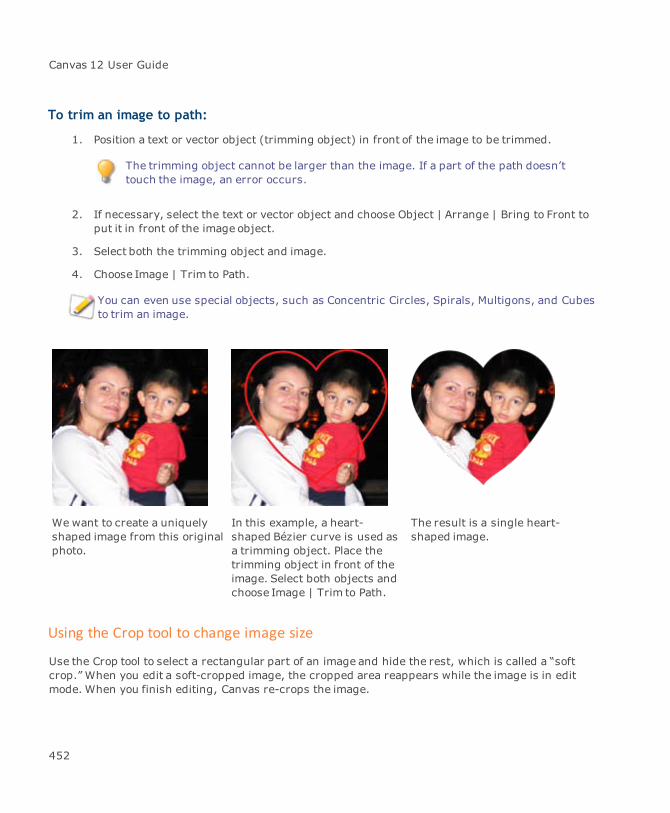
Canvas 12 User Guide
To trim an image to path:
1. Position a text or vector object (trimming object) in front of the image to be trimmed.
The trimming object cannot be larger than the image. If a part of the path doesn’ttouch the image, an error occurs.
2. If necessary, select the text or vector object and choose Object | Arrange | Bring to Front toput it in front of the image object.
3. Select both the trimming object and image.
4. Choose Image | Trim to Path.
You can even use special objects, such as Concentric Circles, Spirals, Multigons, and Cubesto trim an image.
We want to create a uniquelyshaped image from this originalphoto.
In this example, a heart-shaped Bézier curve is used asa trimming object. Place thetrimming object in front of theimage. Select both objects andchoose Image | Trim to Path.
The result is a single heart-shaped image.
Using the Crop tool to change image size
Use the Crop tool to select a rectangular part of an image and hide the rest, which is called a “softcrop.” When you edit a soft-cropped image, the cropped area reappears while the image is in editmode. When you finish editing, Canvas re-crops the image.
452
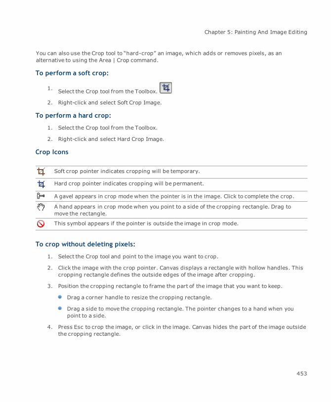
Chapter 5: Painting And Image Editing
You can also use the Crop tool to “hard-crop” an image, which adds or removes pixels, as analternative to using the Area | Crop command.
To perform a soft crop:
1. Select the Crop tool from the Toolbox.
2. Right-click and select Soft Crop Image.
To perform a hard crop:
1. Select the Crop tool from the Toolbox.
2. Right-click and select Hard Crop Image.
Crop Icons
Soft crop pointer indicates cropping will be temporary.
Hard crop pointer indicates cropping will be permanent.
A gavel appears in crop modewhen the pointer is in the image. Click to complete the crop.
A hand appears in crop modewhen you point to a side of the cropping rectangle. Drag tomove the rectangle.
This symbol appears if the pointer is outside the image in crop mode.
To crop without deleting pixels:
1. Select the Crop tool and point to the image you want to crop.
2. Click the image with the crop pointer. Canvas displays a rectangle with hollow handles. Thiscropping rectangle defines the outside edges of the image after cropping.
3. Position the cropping rectangle to frame the part of the image that you want to keep.
Drag a corner handle to resize the cropping rectangle.
Drag a side to move the cropping rectangle. The pointer changes to a hand when youpoint to a side.
4. Press Esc to crop the image, or click in the image. Canvas hides the part of the image outsidethe cropping rectangle.
453

Canvas 12 User Guide
To restore a cropped image:
You can select a paint object and choose Effects | Remove Effects to remove a soft crop. Or, use thefollowing procedure:
1. Click the image with the Crop tool. Canvas displays the full image area and the croppingrectangle.
2. Drag the corner handles outward so the entire image is inside the cropping rectangle, andthen press Esc, or click in the image.
Cropping an image
Adjust the cropping rectangle with the Crop tool by dragging a handle. Enclose the area you want tokeep, and then press Esc to hide the cropped part of the image.
To remove pixels when cropping an image:
In hard-crop mode, the Crop tool discards pixels that are outside the cropping rectangle.
Quickly crop or expand a paint object using the Selection tool. Select the paint object (don’tput it in edit mode), then Ctrl-drag a handle to crop or add pixels to the image. When youdrag, the cropping rectangle and handles appear. When you release the mouse, Canvasapplies a hard crop.
454

Chapter 5: Painting And Image Editing
1. Select the Crop tool and Ctrl-click the image you want to crop. Canvas displays a croppingrectangle around the boundary of the image.
2. Position the cropping rectangle so it frames the part of the image you want to keep.
Drag a handle to resize the cropping rectangle.
Tomove the cropping rectangle, point to any side, and the pointer changes to a hand.Drag the cropping rectangle to reposition it.
3. Press Esc or click in the image to complete the crop.
To add pixels with the Crop tool:
1. Select the Crop tool and point to the image you want to crop.
If the paint object you crop is an Indexed mode object, the color of the added pixels isthe last color in the color table associated with the image, which often is black.
2. Alt-click the image you want to enlarge. Canvas displays a cropping rectangle with hollowsquare handles at the corners.
3. Drag the handles of the cropping rectangle to enlarge it.
4. Press Esc or click in the image to complete the crop.
Adding a white border
When you press a modifier key and click with the Crop tool, you can expand a paint object. This addsa white border to an RGB Color or CMYK Color image.
To quickly crop an image with the Selection tool:
1. When a paint object is selected (not in edit mode), point to a handle, and then press Ctrl anddrag the handle. When you drag, a cropping rectangle appears.
2. Drag inward to crop (cut away) part of the object. Drag outward to add pixels and expandthe object. Release the mouse to complete the operation.
To constrain the cropping rectangle as you drag:
Do one or more of the following:
To constrain the height and width of the cropping rectangle proportionally: Release theCtrl key, and then press Shift while dragging.
455
Canvas 12 User Guide
To constrain the height and width of the cropping rectangle symmetrically from thecenter: Release the Ctrl key and then press it again while dragging.
To constrain the height and width of the cropping rectangle both proportionally andsymmetrically: Release the Ctrl key and then press Ctrl+Shift while dragging.
Changing resolution
Change the resolution of paint objects in two ways:
If you do not want to change an object’s size, resample the image. Resampling merges ordivides pixels.
If you want to preserve all the data in an image, change the object’s resolution and allow itssize to change.
Decreasing resolution (“down sampling”) decreases file size by discarding data, which can result inlost detail; however, it’s common to reduce resolution in some situations.
For Web pages and other applications where images are displayed on a monitor, 72 ppi isthe standard resolution.
Rarely, an image is resampled to increase resolution. This should be avoided because additionalpixels are created by estimating their color values, which does not improve an image.
The Resolution dialog box has compact and expanded states. In its compact state, you can easilychange the resolution of multiple paint objects without needing to specify additional options (see"Image resolution settings" on page 456).
Image resolution settings
Specify the resolution, width, and height for a selected paint object when the Image Resolution dialogbox is expanded. Expand the dialog box when a single paint object is selected; if multiple objects areselected, they must match in size and resolution.
Depending on the options you select, certain settings in the dialog box can’t be changed. A bracketand chain icon indicate settings that are linked and fixed.
Preserve Data: Prevents resampling, or interpolation, when resolution or size changes.Selecting Preserve Data also selects Preserve Proportions, so width and height change only inproportion to each other.
Preserve Datameans image resolution and size are relative; changing the resolution will changethe object size, and changing the size will change the image resolution.
456
Chapter 5: Painting And Image Editing
If you select Pixels in theWidth and Height menus, you cannot change these values, becausethe number of pixels cannot change when Preserve Data is selected.
Width and Height: Specify a size for the paint object by entering values in these textboxes. Select measurement units in the adjacent menus.
The width and height boxes show the size a paint object will become if you change theresolution when Preserve Data is selected.
Preserve Proportions: This option links theWidth and Height values so that changing onevalue changes the other and maintains the original proportions of the paint object. SelectingPreserve Data also selects this option. If you want to stretch a paint object in only onedirection, deselect Preserve Proportions.
When more than one paint object is selected (unless the objects are the same size andresolution), the button that displays additional options in the Resolution dialog box is notavailable.
To change resolution by resampling:
This procedure reduces resolution of paint objects for use on a Web page or in a presentation.
1. Select one or more paint objects. These objects can vary in size and resolution.
2. Choose Image | Area | Resolution. The Image Resolution dialog box appears in its compactstate.
3. Select pixels per inch or pixels per centimeter and enter the resolution value in the text box.
4. Click OK. Canvas changes the resolution of the selected objects, which remain the same size.
To change resolution without resampling:
Use this procedure to change the resolution of paint objects without resampling. This changes thesize of objects while preserving the image data.
If you reduce resolution, paint objects become larger because the individual pixels are larger. If youincrease resolution, paint objects become smaller because the individual pixels are smaller.
1. Select one or more paint objects and choose Image | Area | Resolution.
2. In the Image Resolution dialog box, select Preserve Data.
3. Enter the desired resolution in the text box and click OK. Canvas changes the resolution ofthe selected paint objects.
457
Canvas 12 User Guide
To calculate resolution:
If only one object is selected, you can calculate an appropriate resolution based on a halftone screenfrequency.
1. Click Auto in the Image Resolution dialog box.
2. Enter the screen frequency and choose Draft, Good, or Best. Canvas calculates the resolutionby multiplying the screen frequency by 1 (draft), 1.5 (good), or 2 (best).
3. Click OK to enter the calculated resolution in the Image Resolution dialog box.
Resampling and sharpening images
Resizing and resampling causes images to appear softer. However, you can apply the Unsharp Maskfilter to bring soft images back into focus. For more information, see "To apply the Unsharp Maskfilter:" on page 480.
To specify how Canvas approximates new pixels:
When increasing image resolution, Canvas uses one of twomethods to calculate color values for thepixels it adds to an image. To change themethod, use the Interpolation control in the ConfigurationCenter.
1. Choose File | Configuration Center. Select the Painting manager in the General settings.
2. Select an option under Interpolation and click OK. For more information, see "Settingpreferences" on page 97.
Auto-tracing images
You can use the Auto Trace command to create vector objects from an image. The Auto Tracecommand traces an entire image or any channel of an image and is available when a paint object isselected. Auto-tracing is much faster than tracing an image by hand with the Polygon or Curve tool,although you might need to edit the resulting vector paths. When Canvas performs an auto-trace, theoriginal image is not changed. When the tracing is complete, you can move the vector objects awayfrom the image.
Canvas auto-traces high-resolution images better than low-resolution images. Auto-tracingan image with a resolution lower than 300 ppi can produce jagged paths.
Canvas traces an image with curves or straight path segments. Auto-tracing usually producesseveral paths that follow various sections of the image. After tracing, group and edit the resultingpaths.
458
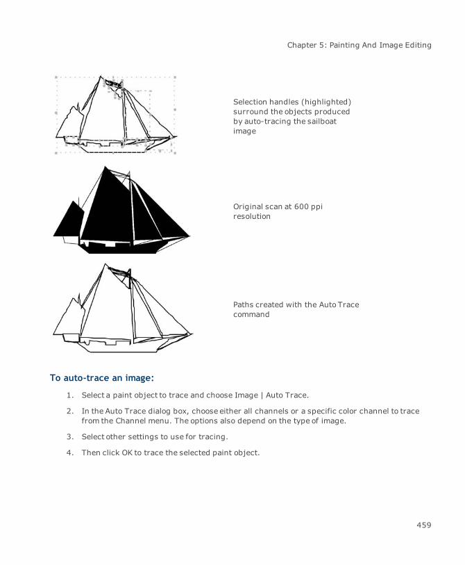
Chapter 5: Painting And Image Editing
Selection handles (highlighted)surround the objects producedby auto-tracing the sailboatimage
Original scan at 600 ppiresolution
Paths created with the Auto Tracecommand
To auto-trace an image:
1. Select a paint object to trace and choose Image | Auto Trace.
2. In the Auto Trace dialog box, choose either all channels or a specific color channel to tracefrom the Channel menu. The options also depend on the type of image.
3. Select other settings to use for tracing.
4. Then click OK to trace the selected paint object.
459

Canvas 12 User Guide
Auto Trace settings
Input The Input section contains information about the image being traced.
Channels: Depending on the image type, you can select All Channels ora specific color Channel from themenu. If the image contains only onecolor channel, like grayscale or black & white, the Channel option andmenu is disabled.
Blur: Use the slider to apply a blur radius to the input image. Blurringremoves noise.
Threshold: This slider is only enabled when the input image isgrayscale or color and the output result is black & white. The threshold,in this case, modifies the intermediate black & white image used tocreate the vector (traced) objects.
Resolution: This slider adjusts the resolution of the input image. Theinput image can be traced at its original resolution or at an adjusted one.
The Intermediate Preview indicates the image used for tracing afterapplying the blur or threshold changes, if applicable.
Output Output section
Mode: Select either Black & White, Grayscale, or Color for the outputtracing.
Trace: Select either Fill, Stroke, or Fill+Stroke. The Fill option createsfilled outlines. The Stroke option is only available when the mode is set toBlack & White. Strokemeans that centerlines with an approximate widthare created rather than outlines. With the Fill+Stroke option, a mixtureof filled vector objects and strokes is made. Strokes are createddepending on the values for Max Stroke Width and Min Stroke Length.
Ignore area less than: This option works as a despeckle filter. Ifisolated pixels or groups of pixels exist in the input image, they will beignored, instead of creating vector objects from them.
Gray Levels: This slider is only enabled when the output is gray orcolor. When the output is gray, the level value defines the number ofgray levels in the intermediate preview and in resulting vector object.When the output is color, the slider controls how well the details in theimage are distinguished. A high value provides better distinction.
Optimize curves: This option reduces the number of points in thecurve, without drastically affecting the shape. Optimize is disabled ifMake polygons is enabled.
460
Chapter 5: Painting And Image Editing
Make polygons: Select this option to create polygons rather than Béziercurves.
The Output preview displays a portion of the resulting vector objects.
Image adjustment & correction
You can adjust images in Canvas using built-in filters and third-party plug-ins. For example, you canuse the Levels filter to adjust image highlights and shadows, and sharpen scanned photos with theUnsharp Mask filter.
This section describes the commands you can use to adjust image color and brightness. It alsodescribes commands for sharpening, softening, and refining images.
Applying image-editing commands
You can applymost image-editing commands to a single paint object if it’s selected or in editmode.You can also apply most commands tomultiple selected paint objects. You can set imagemodes, apply filters, and adjust settings for multiple paint objects at the same time.
In most cases, a command affects an active selection, or an entire image if nothing is selected in editmode.
When you apply an image-editing command tomore than one selected paint object, youcan’t use the Preview option if the dialog box has it. Preview is available when a single imageis in edit mode.
You can apply a command by choosing Image | Adjust or by using the Adjust menu located in theProperties bar.
The following summarizes how image-editing commands can be applied.
Mode commands let you set the image mode for one or more selected paint objects.
You can convert multiple objects to image proxies.
Crop command and the Proxy Info command can’t be applied to multiple objects.
Resolution command sets the resolution for one or more selected objects.
Trim command trims one or more selected paint objects.
461
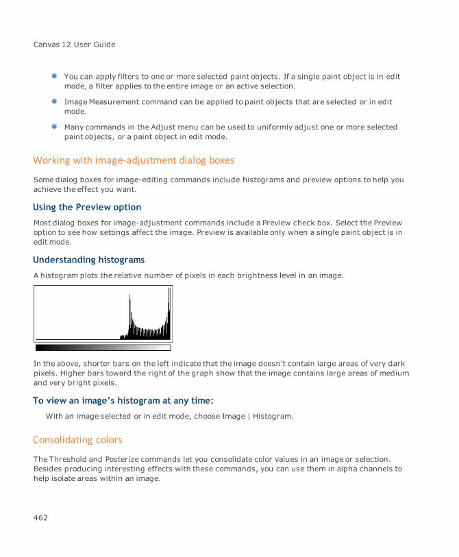
Canvas 12 User Guide
You can apply filters to one or more selected paint objects. If a single paint object is in editmode, a filter applies to the entire image or an active selection.
ImageMeasurement command can be applied to paint objects that are selected or in editmode.
Many commands in the Adjust menu can be used to uniformly adjust one or more selectedpaint objects, or a paint object in edit mode.
Working with image-adjustment dialog boxes
Some dialog boxes for image-editing commands include histograms and preview options to help youachieve the effect you want.
Using the Preview option
Most dialog boxes for image-adjustment commands include a Preview check box. Select the Previewoption to see how settings affect the image. Preview is available only when a single paint object is inedit mode.
Understanding histograms
A histogram plots the relative number of pixels in each brightness level in an image.
In the above, shorter bars on the left indicate that the image doesn’t contain large areas of very darkpixels. Higher bars toward the right of the graph show that the image contains large areas of mediumand very bright pixels.
To view an image’s histogram at any time:
With an image selected or in edit mode, choose Image | Histogram.
Consolidating colors
The Threshold and Posterize commands let you consolidate color values in an image or selection.Besides producing interesting effects with these commands, you can use them in alpha channels tohelp isolate areas within an image.
462
Chapter 5: Painting And Image Editing
If you select an areawithin an image, Canvas applies the adjustment only to that area. Otherwise,Canvas adjusts the selected paint objects.
Setting a brightness threshold
Use the Threshold command to convert any image to black and white. The Threshold commandcompares each pixel’s brightness value to a threshold value that you set. It changes brighter pixelsto white and darker pixels to black. The threshold setting is based on a scale of brightness valuesfrom 0 (black) to 255 (white). You can’t use the Threshold command on images in Black & White orIndexed mode.
For example, if you set a threshold value of 128, pixels that are brighter than medium gray becomewhite, while pixels darker than medium gray become black.
To map an image to black and white:
1. Select one or more paint objects to adjust all the images. You can select an area in one imagein edit mode to adjust the selected area only. If you don’t make a selection, the entire imageis affected.
2. Choose Image | Adjust | Threshold.
3. Enter the threshold value by dragging the slider or typing a number in the text box. If youwant Canvas to convert half the pixels to black and half to white, click Auto.
4. Click OK after entering the setting you want.
To isolate selections, apply the Threshold command in conjunction with the High Pass filter to animage in an alpha channel (see "Isolating areas using the High Pass filter" on page 538).
Creating high contrast posterized images
You can condense the brightness variations in an image with the Posterize command. If you apply thePosterize command to a photograph, it creates a high-contrast image by compressing hundreds ofbrightness levels into only a few. You set the number of brightness levels you want to retain, andCanvas reduces each color channel to that number of values.
463

Canvas 12 User Guide
Original RGB image Posterize 8 levels
Posterize 4 levels Posterize 2 levels
The Posterize command’s effect depends on the mode of the image you posterize; e.g., if you applythe Posterize command with a setting of 2 levels to a grayscale-mode image, the image becomesblack and white. If you apply the same setting to an RGB-mode image (even if it contains only grays),the command converts each pixel’s red, green, and blue value to either zero or full color, reducingthe image to eight colors — red, green, blue, red-green, red-blue, blue-green, black, and white.
You can’t use the Posterize command on images in Black & White or Indexed mode.
464

Chapter 5: Painting And Image Editing
To posterize an image:
1. Select one or more paint objects to posterize all the images. You can select an area in oneimage in edit mode to posterize the selected area only. If you don’t make a selection, theentire image is affected.
2. Choose Image | Adjust | Posterize.
3. Enter a level from 2 to 255. Higher numbers produce subtle effects. Lower numbers producehigh-contrast images.
4. Click OK after you enter the Levels setting.
Changing color and contrast
You can use the Invert, Desaturate, and Brightness/Contrast commands to create special effects andcorrect lightness levels in images. These commands apply changes equally to all color values.
If you select an area of an image, Canvas applies the command to that area only. Otherwise, Canvasapplies the command to the entire image in a paint object.
Inverting colors in images
You can use the Invert command to reverse the colors in an image, as in a photographic negative.The command converts each pixel’s color to its opposite hue in the color spectrum. It does this byinverting the brightness value of each pixel in each color channel.
For example, if a pixel is pure red, its brightness levels are 255, 0, 0 in RGBmode. When inverted,this pixel’s brightness values become 0, 255, 255, changing it to pure blue-green, its opposite inhue.
465
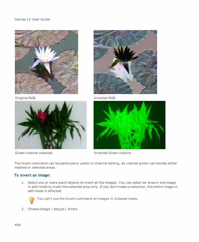
Canvas 12 User Guide
Original RGB Inverted RGB
Green channel selected Inverted Green channe
The Invert command can be particularly useful in channel editing, as colored pixels can denote eithermasked or selected areas.
To invert an image:
1. Select one or more paint objects to invert all the images. You can select an area in one imagein edit mode to invert the selected area only. If you don’t make a selection, the entire image inedit mode is affected.
You can’t use the Invert command on images in Indexed mode.
2. Choose Image | Adjust | Invert.
466
Chapter 5: Painting And Image Editing
Desaturating image colors
You can use the Desaturate command to remove color from images completely, while retaining therelative brightness levels of shadows, midtones, and highlights. The command converts an entireimage to shades of gray without changing the image mode.
To desaturate an image:
1. Select one or more paint objects to desaturate all the images. You can select an area in oneimage in edit mode to desaturate the selected area only. If you don’t make a selection, theentire image in edit mode is affected. This command works with paint objects in RGB Colormode, CMYK Color mode, and LAB Color mode.
2. Choose Image | Adjust | Desaturate or select Desaturate from the Adjust menu in theProperties bar.
Adjusting brightness and contrast
You can adjust the brightness and contrast of an entire image or specific channels with theBrightness/Contrast command. Brightness refers to the lightness of an image. Contrast is thedifference in brightness between two pixels.
Because the Brightness/Contrast command adjusts all pixels equally, you should avoid using it tolighten an image that appears too dark, because the image can lose shadow detail.
To preserve shadows or highlights when adjusting the brightness of an image:
Use the Levels or Curves commands (see "Levels" on page 468 and "Adjusting brightness curves"on page 470).
To use the Brightness/Contrast command:
1. Select one or more paint objects to adjust all the images. You can select an area in one imagein edit mode to adjust the selected area only. If you don’t make a selection, the entire imagein edit mode is affected. This command doesn’t work with paint objects in Black & Whitemode or Indexed mode.
2. Choose Image | Adjust | Brightness/Contrast or select Brightness/Contrast from the Adjustmenu in the Properties bar.
3. Enter a Brightness value from -100 to 100. Higher values can wash out midtones andshadows. Lower values can dull highlights.
467
Canvas 12 User Guide
4. Enter a Contrast value from -100 to 100. Increasing contrast moves the color values of pixelsto the extremes of the brightness spectrum. Decreasing contrast moves color values towardmediumgray.
5. After entering the settings you want, click OK.
Color balance
The Color Balance command lets you adjust color in shadows, midtones, and highlights. You can useit with paint objects in CMYK Color or RGB Color modes.
To use the Color Balance command:
1. Select one or more paint objects to adjust all the images. You can select an area in one imagein edit mode to adjust the selected area only. If you don’t make a selection, the entire imagein edit mode is affected.
2. Choose Image | Adjust | Color Balance.
3. Click Shadows, Midtones, or Highlights to select the tonal range you want to adjust. You canset the color levels independently for each tonal range.
4. Drag a slider toward a color label to increase the amount of that color. The letters indicatethe primary color values: Cyan, Red, Magenta, Green, Yellow, and Blue.
When you increase the amount of a color, you also reduce its inverse, which is the colorlabeled at the other end of the slider.
5. Click Preview to preview the color adjustments. Preview is only available if a single paintobject is in edit mode.
6. Click OK to apply the settings.
Levels
You can adjust the brightness of shadows, highlights, or midtones by using the Levels command.Brightness values range from 0 (black) to 255 (white). For colored pixels, brightness is thebrightness value in each color channel.
The Levels command works with all image modes except Black & White and Indexed.
To adjust levels:
1. Select a paint object to adjust. You can select an area in the image to adjust the selected areaonly.
468
Chapter 5: Painting And Image Editing
2. Choose Image | Adjust | Levels.
3. Select a channel or combination of channels in the pop-up menu. The Levels command willaffect only the specified channels.
4. Do one or more of the following:
Lighten highlights: Enter a positive number less than 255 in the right Input Levelsbox, or drag the white slider under the histogram. Canvas assigns the maximum outputlevel to all pixels on the right of the slider.
Lighten shadows: Enter a positive number in the left Output Levels box, or drag theblack slider under Output Levels to increase theminimum output level. This valuebecomes the darkest value allowed in the image.
Darken highlights: Enter a positive number less than 255 in the right Output Levelsbox, or drag the white slider under Output Levels to set the maximum output value. Thisis the brightest value allowed in the image. You can darken highlights in one colorchannel to bring brighter colors back into the printable color range.
Darken shadows: Enter a number greater than zero in the left Input Levels box, or dragthe black slider under the histogram. Canvas assigns theminimum output level to allpixels on the left of the slider.
Adjust midtones: Enter a value in the center Input Levels box or drag the gray sliderunder the histogram. To lighten midtones, enter a value from 1.01 to 9.99 or drag theslider to the left. All pixels on the right of the slider will be brighter than medium gray. Todarken midtones, enter a value from 0.1 to 1.00 or drag the slider to the right. All pixelson the left of the slider will be darker than medium gray.
5. Click OK.
Saving and loading Levels settings
You can save Levels settings on disk to use again. For example, after correcting a scanned photo, youcan save the settings and use them to correct other images scanned from the same source.
To save Levels settings:
1. In the Levels dialog box, click Save.
2. In the dialog box, type a name for the settings file, select a location, and click Save.
To load previously-saved Levels:
1. In the Levels dialog box, click Load.
2. In the dialog box, locate the settings file you want to open, and click Open.
469
Canvas 12 User Guide
Levels dialog box
Use the Levels dialog box to control different aspects of brightness levels.
Channel Choose an individual color channel or the composite channel.
Input Levels Type values in the Input Levels boxes or drag the slider under thehistogram to set theminimum input level, midtone ratio, and maximuminput levels.
Output Levels Type values in the Output Levels boxes or drag the sliders to set theminimum and maximum output levels.
Histogram The histogram graphs brightness levels for the selected channel.
Auto Click Auto for Canvas to map the darkest values in the selection to blackand the lightest value to white.
Eyedroppers Click the Set White Point eyedropper tool. Click in the image to pick thevalues you want to assign to the lightest area in the image. Click the SetBlack Point eyedropper tool. Click in the image to pick the values youwant to assign to the darkest area in the image.
Adjusting brightness curves
You can adjust the tonal range of an image with the Curves command. Unlike the Levels command,which can set the minimum, maximum, and median values, Curves adjusts the entire range ofvalues. It lets you map input values to output values according to a line (“curve”) on a graph. Curvesprovides themost control over the tonal range of an image.
This command is not available when a paint object in Black & Whitemode or Indexed mode isselected.
In the Curves dialog box, brightness values range from 0 (black) to 255 (white), or 0 percent (white)to 100 percent (black). To switch between these scales, click the grayscale bar under the graph.
A typical setting is a gentle S-curve (or inverted S-curve, depending on the scale you use), whichadds contrast to an image without appearing too harsh.
Curves dialog box
The graph shows how Canvas maps input brightness values to output values. Select Preview to seethe effect on the image.
Channel Choose a channel to adjust.
470
Chapter 5: Painting And Image Editing
Grayscale ramp The grayscale ramp shows the lightness scale, either 0-255 (dark tolight) or 0-100 percent (light to dark). Click the ramp to reverse thescale and the curve.
Input and Output Type brightness values in the Input and Output boxes. Or, drag thepointer (circled) to specify brightness values.
Icon Click this icon and drag a point on the curve to reshape the curve. Clickthe curve to add up to 19 control points. Drag points off the curve todelete them.
To draw a disconnected segment, click this icon and drag in the graph.
Pencil With the pencil selected, click to smooth the curve.
To adjust brightness curves:
1. Select one paint object to adjust. The paint object can be in edit mode. You can select anarea in the image. If you don’t make a selection, the entire image is affected.
2. Choose Image | Adjust | Curves.
To redraw the curve completely, or to create sharp changes in brightness for a tonalrange, click the pencil and draw a new curve or segment.
3. In the Channel pop-up menu, select the composite channel or an individual channel toadjust. To adjust multiple channels, select the channels in the Channels palette first.
4. To change the shape of the existing curve, make sure the curve button at the bottom-left isselected.
Click points that you want to keep the same.
Drag points on the curve that you want to change. Or, enter values in the Input andOutput boxes. For example, to keep midtones the same, click the center of the curve, thendrag other areas of the curve. To adjust midtones without affecting highlights andshadows, click the quarter and three-quarter points of the curve, and drag the middle.
5. If you draw disjointed segments with the pencil, you can click Smooth to create onecontinuous curve.
6. Click OK to apply the current settings to the image.
471
Canvas 12 User Guide
Saving and loading Curves dialog box settings
You can save Curves dialog box settings to use again; e.g., after correcting the brightness curve fora particular Photo CD image, you can save these settings and later apply them to other images fromthe same source.
To save Curves settings:
In the Curves dialog box, click Save. In the directory dialog box, type a name for the settings file,select a location, and click Save.
To load Curves settings:
In the Curves dialog box, click Load. In the directory dialog box, locate the settings file and clickOpen.
Hue/Saturation
You can modify the tint and purity of specific colors with the Hue/Saturation command. In terms ofimage editing, saturation refers to the amount of gray in colors.
The Hue/Saturation dialog box varies slightly depending on the color mode. For RGB Color and CMYKColor images, you can modify red, yellow, green, cyan, blue, or magenta color ranges. For LAB modeimages, you can modify blue, magenta, yellow, or green color ranges.
The Hue/Saturation command is available when you work with CMYK, RGB, or LAB Color modeimages. Before choosing the Hue/Saturation command, make the composite channel active. For moreinformation, see "Activating channels" on page 508.
Hue/Saturation dialog box
Color Choose the color to adjust. Click Master to affect all colors.
Hue, Saturation,Lightness
Enter numbers in the text boxes or drag the sliders to adjust hue,saturation, and lightness.
Color Wheel The color wheel illustrates changes made in the settings.
Colorize Select the Colorize check box to add the same hue to the entire image.
To adjust the hue of a color range:
1. Select a paint object to adjust. You can select an area in the image to adjust the selected areaonly.
2. Choose Image | Adjust | Hue/Saturation.
472

Chapter 5: Painting And Image Editing
3. On the left of the dialog box, click the color range to adjust, or click Master to affect all colorsequally.
4. To change the selected color, enter the amount of the color shift, from -180 to 180°, in theHue text box. Negative values indicate a counter-clockwise shift around the color wheel;positive values indicate a clockwise shift; e.g., with the Master option selected, setting Hueto 60 changes red tomagenta, magenta to blue, blue to cyan, and so on.
5. Click OK to apply the current settings to the image.
To adjust the saturation of a color range:
1. Select a paint object to adjust. You can select an area in the image to adjust the selected areaonly.
2. Choose Image | Adjust | Hue/Saturation.
3. Click the option button of the color you want to adjust, or click the Master option button toaffect all colors equally.
4. Enter a value from -100 to 100 in the Saturation text box or drag the slider. Positive valuesdecrease the amount of gray in the selected colors. Negative values increase the amount ofgray.
5. Click OK to apply the current settings to the image.
To adjust the brightness of a color range:
1. Select a paint object to adjust. You can select an area in the image to adjust the selected areaonly.
2. Choose Image | Adjust | Hue/Saturation.
3. Choose a specific color range or choose Master to affect all colors equally.
4. Enter a value from -100 to 100 in the Lightness text box or drag the slider. Positive valuesincrease the amount of white in the color range. Negative values decrease the amount ofwhite.
5. Click OK to apply the current settings to the image.
For more control of brightness adjustments, use the Levels or Curves command (see "Levels" onpage 468 and "Adjusting brightness curves" on page 470).
To colorize an image:
Use the Colorize option in the Hue/Saturation dialog box to tint an image. This applies the same hueand saturation to all pixels that are not 100% black or white. The Colorize option does not affect the
473

Canvas 12 User Guide
lightness levels of pixels.
1. Select a paint object. You can select an area in the image to adjust only the selection.
2. Choose Image | Adjust | Hue/Saturation.
3. Select the Colorize option.
4. Enter a value from -180° to 180° in the Hue text box. Positive values shift counter-clockwisearound the color wheel, negative values shift clockwise around the color wheel. For example,Hue 120 creates a green-toned image.
5. Enter a value in the Saturation text box or drag the slider.
6. After entering the settings you want, click OK.
Color Equalization
You can graphically adjust the saturation of different color ranges with the Color Equalizationcommand. You can add or remove gray from various color ranges in images in RGB Color mode, CMYKColor mode, and LAB Color mode.
To use the Color Equalization command:
1. Select a paint object to adjust. You can select an area in the image to adjust only the selectedarea.
2. Choose Image | Adjust | Color Equalization.
3. Drag the handles in the window to change the saturation of color ranges. To increasesaturation, drag upward. To decrease saturation, drag downward.
4. Click Saturate to increase the saturation of all colors. To decrease the saturation of all colors,click Desaturate. Click Normalize to return all colors to their original saturation.
5. Click OK to apply the settings.
Blur filters
Blur filters soften images by decreasing contrast between neighboring pixels. These commands workwith all image modes except Indexed and Black & White.
Apply the Blur filters by choosing Image | Filter | Blur or by using the Filters menu in the Propertiesbar.
474

Chapter 5: Painting And Image Editing
To use Blur and Blur More:
Blur slightly modifies an image. Blur More is about four times stronger than Blur. Both commandswork with all image modes except Black & White and Indexed.
1. Select one or more paint objects to blur. You can select an area in one image to blur theselected area only.
2. Choose Image | Filter | Blur | Blur or Blur More.
Gaussian and Average blur
Create a softening effect by using the Gaussian Blur or Average blur filters. Their effects are similar,but the Gaussian Blur filter creates a more diffused effect than the Average blur filter.
The Gaussian Blur filter changes the color value of each pixel by applying a weighted average basedon the color values of pixels within a specified distance. Color values at the edge of the specifieddistance influence the final color value less than closer pixels.
The Average filter determines the new color value for each pixel by equally averaging all color valueswithin the specified radius.
To apply Gaussian Blur or Average blur:
1. Select one or more paint objects to blur. You can select an area in one image to blur theselected area only.
2. Choose Image | Filter | Blur | Gaussian Blur or Average.
3. Specify a radius value from 0.1 to 250.0 in the Gaussian Blur dialog box, or 1 to 16 in theAverage dialog box. Smaller radius values produce more subtle effects than larger ones.
4. Click OK.
Depending on the size of the radius, applying a Gaussian or Average blur can take longer than otherBlur filters.
Blur Blur More Average Gaussian
475

Canvas 12 User Guide
Motion Blur
The Motion Blur filter can create the effect of linear movement. You can specify the direction andmagnitude of the effect. This command works with all imagemodes except Black & White, Indexed,and Duotone.
To apply motion blur:
1. Select one or more paint objects to blur. You can select an area in one image to blur theselected area only.
2. Choose Image | Filter | Blur | Motion Blur. Adjust the settings in the Motion Blur dialog box,and then click OK to apply the filter and close the dialog box.
Original Motion Blur: Direction = -7, Distance = 162, Phase= -63
476
Chapter 5: Painting And Image Editing
Motion Blur dialog box
Direction Establishes the angle of the blur and the object “movement.” Enter avalue from -90 to 90 degrees. You can drag the slider or drag the soliddot inside the circle to set the Direction value. A value of 0 degreescreates a horizontal blur; 90 degrees creates a vertical blur.
Distance Themagnitude of the blur. Enter a number from 1 to 999, or drag theslider to set the Distance. A lower number creates less blurring.
Phase Establishes the apparent direction of movement by creating a blurredtrail that follows the object. Enter a number from -100 to 100 or dragthe slider to set the Phase. Negative numbers create apparent movementup and to the right. Positive numbers create apparent movement downand to the left.
Preview Displays the effect of the current settings.
Radial Blur
The Radial Blur filter can create the effect of circular movement in an image. This command workswith all image modes except Black & White, Indexed, and Duotone.
To apply radial blur:
1. Select one or more paint objects to blur. You can select an area in one image to blur theselected area only.
2. Choose Image | Filter | Blur | Radial Blur. Adjust the settings in the dialog box, and then clickOK to apply the filter.
477
Canvas 12 User Guide
Radial Blur dialog box
Spin Controls themagnitude of the apparent rotation in the image. Type anumber from 1 to 100 or drag the slider to set the value. Or, drag thesolid area inside the circle. Drag clockwise to simulate slower rotation;drag counterclockwise to simulate faster rotation and produce moreblurring.
Quality Higher quality creates a smoother image but takes more time. Thequality differences become more pronounced when the image isenlarged or printed on standard size paper.
Select Draft for the fastest redraw. Select Good for average redrawspeed and quality. Select Best when image quality is most important.
Centering options These options let you set the rotation origin. Center In Image sets theorigin at the center of the image. Center in Selection sets the origin atthe center of a selection. “Offset from Center in Pixels” lets you typevalues to offset the origin from the center of the image or selection. Typevertical and horizontal offset amounts in pixels in the text boxes.Negative horizontal offsets move the center to the left. Negative verticaloffsets move the center up. Positive horizontal offsets move the center tothe right. Positive vertical offsets move the center down.
Preview Displays the effect of the current settings.
Zoom Blur
The Zoom Blur filter can create the effect of movement in an image, as if the scene weremovingrapidly toward or away from the observer. The filter blurs along an axis perpendicular to the image.You can specify the depth, direction, and smoothness of the blur effect. This command works with allimagemodes except Black & White, Indexed, and Duotone.
To apply zoom blur:
1. Select one or more paint objects to blur. You can select an area in one image to blur theselected area only.
2. Choose Image | Filter | Blur | ZoomBlur. Adjust the settings in the dialog box, and then clickOK to apply the filter.
478

Chapter 5: Painting And Image Editing
Zoom Blur dialog box
Span Sets the depth, (length) of the zoom effect. Type a number from 1 to100 or drag the slider to set the value. A larger number simulates agreater zoomdepth and a more blurred effect.
Zoom In/Out Establishes the direction of the blur effect toward or away from theviewer. Type a number from -100 to 100 or drag the slider to set thevalue. Negative numbers make the image appear tomove closer; positivenumbers make the image appear tomove away.
Smoothness Controls the quality of the transition of the blur effect. Type a numberfrom 1 to 10 or drag the slider to set the value. A smaller number createsa smoother blur with fine color blending.
Centering options These options let you set the zoomorigin. Center In Image sets theorigin at the center of the image. Center in Selection sets the origin atthe center of a selection. “Offset from Center in Pixels” lets you typevalues to offset the origin from the center of the image or selection. Typevertical and horizontal offset amounts in pixels in the text boxes.Negative horizontal offsets move the center to the left. Negative verticaloffsets move the center up. Positive horizontal offsets move the center tothe right. Positive vertical offsets move the center down.
Preview Displays the effect of the current settings.
Sharpen filters
Sharpen filters increase the contrast between adjacent pixels, which can make an image appear moredistinct. These commands work with all imagemodes except Black & White, Indexed, and Duotone.
Although the Sharpen and Blur filters have opposite effects, they do not negate each other.To reverse the effects of a Sharpen filter, choose Edit | Undo.
Sharpen filter: Modifies an image slightly. The effect of the Sharpen More filter is aboutfour times greater.
Sharpen Edges filter: Affects only high-contrast areas.
Unsharp Mask filter: Provides additional control over the sharpening effect.
479
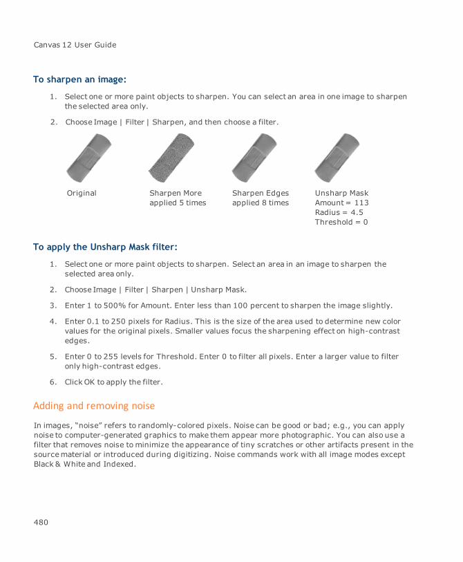
Canvas 12 User Guide
To sharpen an image:
1. Select one or more paint objects to sharpen. You can select an area in one image to sharpenthe selected area only.
2. Choose Image | Filter | Sharpen, and then choose a filter.
Original Sharpen Moreapplied 5 times
Sharpen Edgesapplied 8 times
Unsharp MaskAmount= 113Radius = 4.5Threshold = 0
To apply the Unsharp Mask filter:
1. Select one or more paint objects to sharpen. Select an area in an image to sharpen theselected area only.
2. Choose Image | Filter | Sharpen | Unsharp Mask.
3. Enter 1 to 500% for Amount. Enter less than 100 percent to sharpen the image slightly.
4. Enter 0.1 to 250 pixels for Radius. This is the size of the area used to determine new colorvalues for the original pixels. Smaller values focus the sharpening effect on high-contrastedges.
5. Enter 0 to 255 levels for Threshold. Enter 0 to filter all pixels. Enter a larger value to filteronly high-contrast edges.
6. Click OK to apply the filter.
Adding and removing noise
In images, “noise” refers to randomly-colored pixels. Noise can be good or bad; e.g., you can applynoise to computer-generated graphics to make them appear more photographic. You can also use afilter that removes noise tominimize the appearance of tiny scratches or other artifacts present in thesourcematerial or introduced during digitizing. Noise commands work with all image modes exceptBlack & White and Indexed.
480
Chapter 5: Painting And Image Editing
To add noise to selections:
1. Select one or more paint objects to adjust. Select an area in one image to adjust the selectedarea only.
2. Choose Image | Filter | Noise | Add Noise.
3. Enter 1 to 999 for Amount to specify how far the color of the noise can vary from the originalcolor.
4. Choose the Uniform or Gaussian distribution option:
Uniform: To apply colors randomly picked within the Amount specified. Canvas evenlydistributes the color of the noise across a range of colors. This option gives the smoothesteffect.
Gaussian: If you want the noise to favor lighter and darker colors within the specifiedrange. This option creates a more pronounced effect than Uniform.
5. Select Monochromatic if you want to add noise of different brightness levels of the originalcolor.
6. Click OK to apply the noise settings.
Removing noise from selections
You can remove noise from an image or selection using the Median, Despeckle, or Dust & Scratchesfilters. The Median filter removes noise by averaging the color of pixels. The Despeckle and Dust &Scratches filters remove noise by selectively blurring regions of the selection.
To use the Median filter:
On a pixel-by-pixel basis, the Median filter applies themedian color value of all pixels within thespecified radius. Although the filter ignores extreme values in its computations, higher radius valuescan still wash out an image.
1. Select one or more paint objects to adjust. You can select an area in one image to adjust theselected area only.
2. Choose Image | Filter | Noise | Median.
3. Type a value from 1 to 16 in the Radius text box, or drag the slider. Smaller radius valuesproduce subtler effects.
4. Click OK.
481
Canvas 12 User Guide
To use the Despeckle filter:
The Despeckle filter can remove defects such as dust and other speckling in images. The filter blendspixels with the lightness values of neighboring pixels. It’s a good idea to select areas that needcorrection before applying the filter.
1. Select an area in an image to adjust. If you don’t make a selection, the entire image isaffected.
2. Choose Image | Filter | Noise | Despeckle.
3. Drag the slider or type a number in the text box to set the Threshold value. Higher valuesproduce greater blending of pixels.
To reduce dust and scratch marks:
The Dust and Scratches filter can remove dust specks by replacing a pixel’s valuewith a medianvalue. The filter does not change a pixel’s value unless the absolute value of the difference of its grayvalue and themedian gray value of its neighborhood is greater than the Threshold. Larger numbersof pixels are replaced by themedian value when the Threshold is low.The practical effect of this isthat larger pixels regions (larger “specks”) are reduced or removed with a lower Threshold.Therefore, you can use the Threshold to control the size of the artifacts you want to remove.
1. Select an area to adjust in an image. If you don’t make a selection, the entire object isaffected.
2. Choose Image | Filter | Noise | Dust & Scratches.
3. Enter a value from 1 to 16 in the Radius text box. Smaller radius values produce a subtlereffect than larger ones.
4. Type a value from 0 to 255 in the Threshold text box. After entering the settings you want,click OK.
Smoothing video images
Because video images contain two interlaced pictures, you can sometimes see a slight banding effectin images acquired from video-recording devices. You can correct this by using the De-Interlacefilter and then applying the Unsharp Mask filter. De-Interlace works with all image modes exceptBlack & White.
To smooth video images:
1. Select one or more paint objects to adjust. You can select an area in one image to de-interlace the selected area only.
482

Chapter 5: Painting And Image Editing
2. Choose Image | Filter | Video | De-Interlace.
3. Click Odd fields or Even fields to select bands to eliminate.
4. Choose a replacement method for the eliminated pixels:
Duplication: To fill the area by inserting a copy of an adjacent band.
Interpolation: To fill the area by inserting intermediate color values based on the colorvalues of neighboring pixels. This option creates a smoother, more accurate fill thanDuplication.
5. After entering the settings you want, click OK.
Selections & channels
Canvas gives you several ways to select pixels in an image. When you select groups of pixels by areaor color, you can use painting tools, filters, and special effects to modify the selected pixels withoutaffecting the parts of the image that are not selected.
This section describes how tomake selections in images, save selections in alpha channels, workwith color and alpha channels, and create channel masks, which can make parts of imagestransparent.
Selecting pixels in images
When a paint object is in edit mode, any filters, commands, and painting tools that you apply canaffect the entire image. When you have selected pixels in the image, the effect of a tool, filter, orother adjustment is confined to the selected pixels.
You can select areas in an image using painting tools or menu commands. For example, you can makerectangular selections by dragging the Marquee tool in an image, and you can use the Color Rangecommand to select groups of pixels based on color similarity.
483

Canvas 12 User Guide
A dashed border outlines theselected area in a photograph
Selection borders
The selected pixels in an image are referred to collectively as a selection. When you make a selection,Canvas surrounds the selected pixels with a moving dashed border. You can hide and display theborder without affecting the selection.
To hide the border:
Choose Image | Select | Hide Edges.
To display the selection border:
Choose Image | Select | Show Edges.
Deselecting an image selection
When you use a selection tool in normal mode, making a new selection replaces any existing selectionin an image.
To deselect pixels without making a new selection:
Choose Image | Select | None. You can also press Esc to deselect a selection. If a selection isfloating, pressing Esc once defloats the selection; pressing Esc again deselects all pixels.
Selecting all pixels in an image
You can apply painting tools and filters to an entire imagewithout first making a selection. But youcan also select all the pixels in an image when you want to work with them as a selection.
484
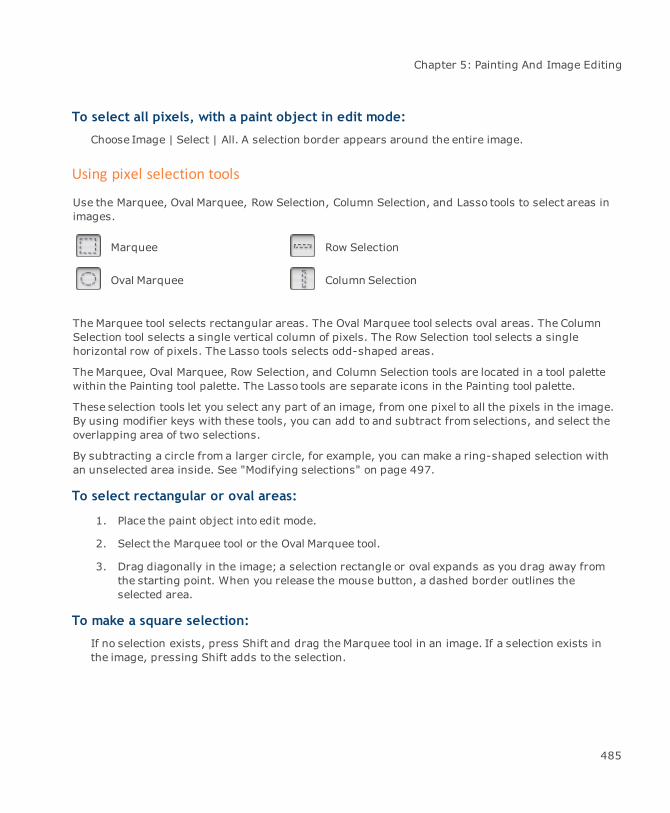
Chapter 5: Painting And Image Editing
To select all pixels, with a paint object in edit mode:
Choose Image | Select | All. A selection border appears around the entire image.
Using pixel selection tools
Use the Marquee, Oval Marquee, Row Selection, Column Selection, and Lasso tools to select areas inimages.
Marquee Row Selection
Oval Marquee Column Selection
The Marquee tool selects rectangular areas. The Oval Marquee tool selects oval areas. The ColumnSelection tool selects a single vertical column of pixels. The Row Selection tool selects a singlehorizontal row of pixels. The Lasso tools selects odd-shaped areas.
The Marquee, Oval Marquee, Row Selection, and Column Selection tools are located in a tool palettewithin the Painting tool palette. The Lasso tools are separate icons in the Painting tool palette.
These selection tools let you select any part of an image, from one pixel to all the pixels in the image.By using modifier keys with these tools, you can add to and subtract from selections, and select theoverlapping area of two selections.
By subtracting a circle from a larger circle, for example, you can make a ring-shaped selection withan unselected area inside. See "Modifying selections" on page 497.
To select rectangular or oval areas:
1. Place the paint object into edit mode.
2. Select the Marquee tool or the Oval Marquee tool.
3. Drag diagonally in the image; a selection rectangle or oval expands as you drag away fromthe starting point. When you release the mouse button, a dashed border outlines theselected area.
To make a square selection:
If no selection exists, press Shift and drag the Marquee tool in an image. If a selection exists inthe image, pressing Shift adds to the selection.
485
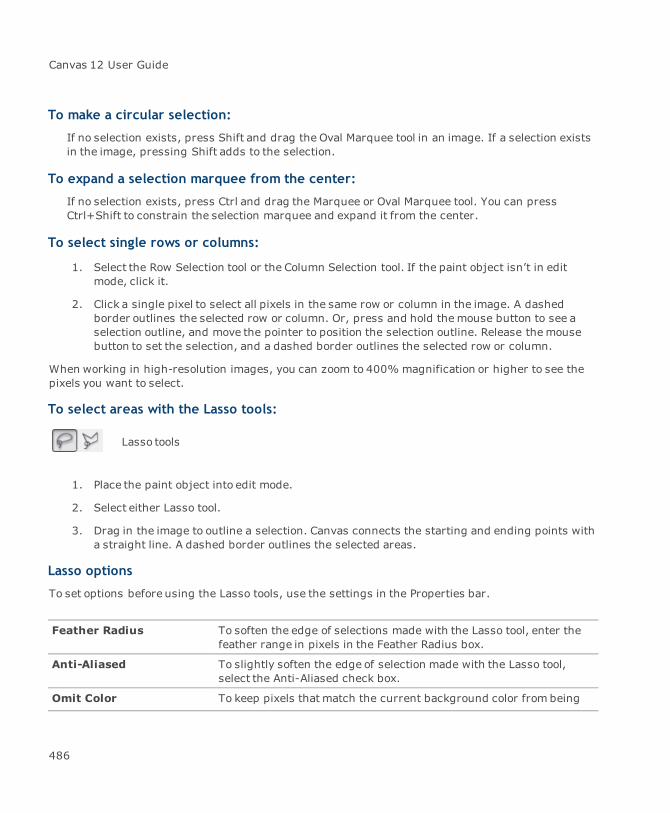
Canvas 12 User Guide
To make a circular selection:
If no selection exists, press Shift and drag the Oval Marquee tool in an image. If a selection existsin the image, pressing Shift adds to the selection.
To expand a selection marquee from the center:
If no selection exists, press Ctrl and drag the Marquee or Oval Marquee tool. You can pressCtrl+Shift to constrain the selection marquee and expand it from the center.
To select single rows or columns:
1. Select the Row Selection tool or the Column Selection tool. If the paint object isn’t in editmode, click it.
2. Click a single pixel to select all pixels in the same row or column in the image. A dashedborder outlines the selected row or column. Or, press and hold themouse button to see aselection outline, and move the pointer to position the selection outline. Release themousebutton to set the selection, and a dashed border outlines the selected row or column.
When working in high-resolution images, you can zoom to 400% magnification or higher to see thepixels you want to select.
To select areas with the Lasso tools:
Lasso tools
1. Place the paint object into edit mode.
2. Select either Lasso tool.
3. Drag in the image to outline a selection. Canvas connects the starting and ending points witha straight line. A dashed border outlines the selected areas.
Lasso options
To set options before using the Lasso tools, use the settings in the Properties bar.
Feather Radius To soften the edge of selections made with the Lasso tool, enter thefeather range in pixels in the Feather Radius box.
Anti-Aliased To slightly soften the edge of selection made with the Lasso tool,select the Anti-Aliased check box.
Omit Color To keep pixels that match the current background color from being
486

Chapter 5: Painting And Image Editing
selected by the Lasso tool, select the Omit Color check box and thenchooseBackground Color. Select Click Point to omit the color whereyou first click with the Lasso tool.
Modifying selections
After you make a selection using any selection technique, you can use modifier keys to alter theselection with the Marquee, Oval Marquee, Row Selection, Column Selection, and Lasso tools.
To add to a selection:
Press Shift when you use a selection tool. A “+” symbol indicates that the tool will add the newselection to the existing selection.
To subtract from a selection:
Press Ctrl when you use a selection tool. A “-” symbol indicates that the tool will subtract the newselection from the existing selection.
To select part of a selection:
Press Shift+Ctrl when you use a selection tool. An “x” symbol indicates that the area you select inthe existing selection will remain selected. If none of the new selection is part of the existingselection, Canvas deselects all pixels.
You can also use Shift or Ctrl to constrain a selection when you add, subtract, or intersect a selection.To do this, press the keys to add, subtract, or intersect and begin dragging. While still pressing themouse button, release the keys and then press the constraint keys and continue dragging.
Selecting areas based on color
You can use the Wand tool and the Color Range command to select pixels in an image according tocolor.
To select a contiguous area of similarly colored pixels:
Use the Wand tool.
To select all pixels of a particular color:
Use the Color Range command.
487
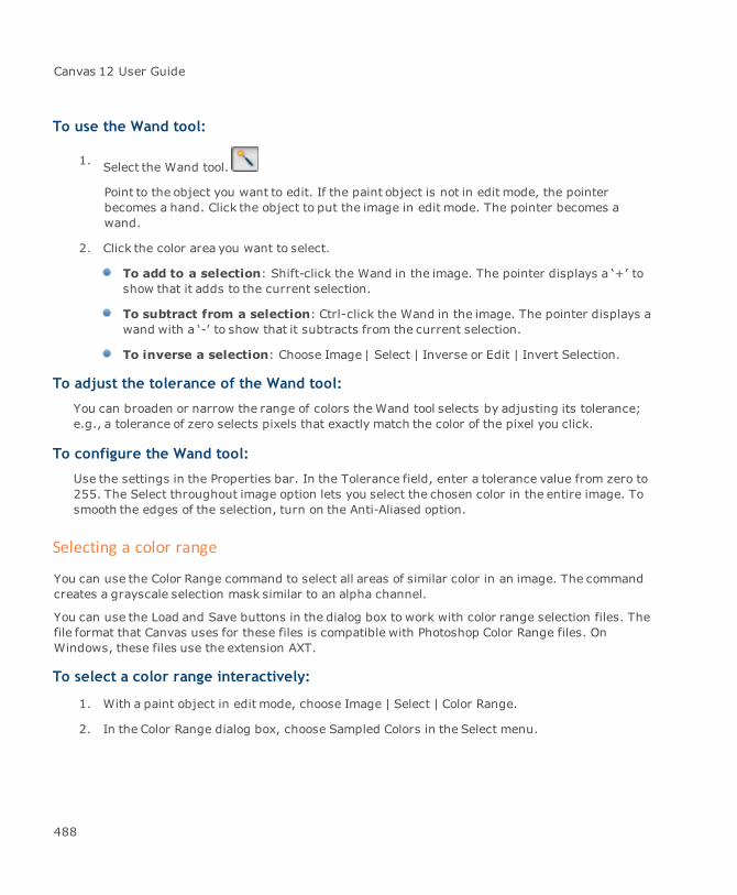
Canvas 12 User Guide
To use the Wand tool:
1. Select the Wand tool.
Point to the object you want to edit. If the paint object is not in edit mode, the pointerbecomes a hand. Click the object to put the image in edit mode. The pointer becomes awand.
2. Click the color area you want to select.
To add to a selection: Shift-click the Wand in the image. The pointer displays a ‘+’ toshow that it adds to the current selection.
To subtract from a selection: Ctrl-click the Wand in the image. The pointer displays awand with a ‘-’ to show that it subtracts from the current selection.
To inverse a selection: Choose Image | Select | Inverse or Edit | Invert Selection.
To adjust the tolerance of the Wand tool:
You can broaden or narrow the range of colors theWand tool selects by adjusting its tolerance;e.g., a tolerance of zero selects pixels that exactly match the color of the pixel you click.
To configure the Wand tool:
Use the settings in the Properties bar. In the Tolerance field, enter a tolerance value from zero to255. The Select throughout image option lets you select the chosen color in the entire image. Tosmooth the edges of the selection, turn on the Anti-Aliased option.
Selecting a color range
You can use the Color Range command to select all areas of similar color in an image. The commandcreates a grayscale selection mask similar to an alpha channel.
You can use the Load and Save buttons in the dialog box to work with color range selection files. Thefile format that Canvas uses for these files is compatible with Photoshop Color Range files. OnWindows, these files use the extension AXT.
To select a color range interactively:
1. With a paint object in edit mode, choose Image | Select | Color Range.
2. In the Color Range dialog box, choose Sampled Colors in the Select menu.
488
Chapter 5: Painting And Image Editing
3. Adjust the Fuzziness setting. To select pixels of exactly the same color, set the Fuzziness tozero. Increase the Fuzziness to widen the range of colors to be selected.
4. Click a color in the preview image in the dialog box. Canvas selects a range of similarlycolored pixels, depending on the Fuzziness setting.
To add colors to the selection, click the ‘+’ dropper icon, then click a color in the image inthe dialog box.
To subtract colors from the selection, click the ‘-’ dropper icon, then click in the image inthe dialog box.
5. To view the selected pixels, click the Selection option. Gray areas indicate pixels that theColor Range command selects at a reduced opacity. Filters and painting tools affect theseareas to a lesser degree than areas that are 100 percent selected. Click OK to apply theselection to the image.
Color Range options
Use this dialog box to select image areas based on color.
Select In themenu, choose the color (red, green, blue, cyan, magenta, yellow),or tonal range (shadows, midtones, highlights) you want to select.
To select a color interactively by clicking in the preview window, chooseSampled Colors.
Fuzziness When using the Sampled Colors option, enter a low value to select anarrow color range; enter a higher value to select a wider range.
Selection ChooseSelection to preview the selection, with white representingselected pixels, in the preview window.
Image Choose Image to see the actual image so you can sample colors with thedropper.
Dropper With Sampled Colors chosen, click the dropper in the preview window toselect colors. Use the ‘+’ dropper to add to the selection; use the ‘-’dropper to subtract from it.
Selection Preview Choose an option to preview the selection in the image itself (or chooseNone for no preview). Grayscale shows the selection as it would appearin a channel, with white for selected pixels and black showing non-selected areas.
The Matte and Mask options show the original colors in selected areas. Innon-selected areas, Black Matte shows black, Whitematte shows white,and Mask shows transparent red.
489

Canvas 12 User Guide
Selecting unselected areas
Use the Inverse command to simultaneously select all pixels not in the current selection whiledeselecting the current selection.
To select areas not included in the current selection:
Choose Image | Select | Inverse.
A moving dashed edge surroundsthe background, a selected area
When the selection is inversed,the cup and its contents areselected
Expanding selections with Grow and Similar
The Grow and Similar commands let you expand selections to include similar colors in an image.These commands compare the colors outside a selection to the colors in the selection. Colors that arein a specified range of similar colors are added to the selection.
490
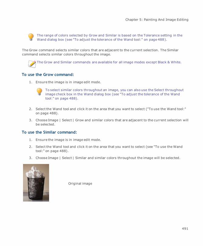
Chapter 5: Painting And Image Editing
The range of colors selected by Grow and Similar is based on the Tolerance setting in theWand dialog box (see "To adjust the tolerance of the Wand tool:" on page 488).
The Grow command selects similar colors that are adjacent to the current selection. The Similarcommand selects similar colors throughout the image.
The Grow and Similar commands are available for all image modes except Black & White.
To use the Grow command:
1. Ensure the image is in image edit mode.
To select similar colors throughout an image, you can also use the Select throughoutimage check box in the Wand dialog box (see "To adjust the tolerance of the Wandtool:" on page 488).
2. Select the Wand tool and click it on the area that you want to select ("To use the Wand tool:"on page 488).
3. Choose Image | Select | Grow and similar colors that are adjacent to the current selection willbe selected.
To use the Similar command:
1. Ensure the image is in image edit mode.
2. Select the Wand tool and click it on the area that you want to select (see "To use theWandtool:" on page 488).
3. Choose Image | Select | Similar and similar colors throughout the image will be selected.
Original image
491
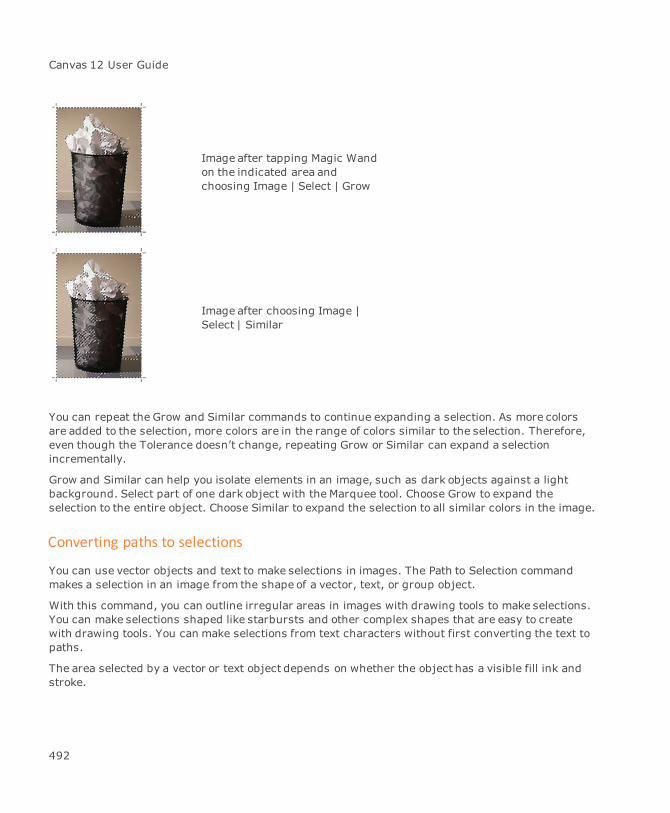
Canvas 12 User Guide
Image after tapping Magic Wandon the indicated area andchoosing Image | Select | Grow
Image after choosing Image |Select | Similar
You can repeat the Grow and Similar commands to continue expanding a selection. As more colorsare added to the selection, more colors are in the range of colors similar to the selection. Therefore,even though the Tolerance doesn’t change, repeating Grow or Similar can expand a selectionincrementally.
Grow and Similar can help you isolate elements in an image, such as dark objects against a lightbackground. Select part of one dark object with the Marquee tool. Choose Grow to expand theselection to the entire object. Choose Similar to expand the selection to all similar colors in the image.
Converting paths to selections
You can use vector objects and text to make selections in images. The Path to Selection commandmakes a selection in an image from the shape of a vector, text, or group object.
With this command, you can outline irregular areas in images with drawing tools to make selections.You can make selections shaped like starbursts and other complex shapes that are easy to createwith drawing tools. You can make selections from text characters without first converting the text topaths.
The area selected by a vector or text object depends on whether the object has a visible fill ink andstroke.
492

Chapter 5: Painting And Image Editing
A filled object will select the area covered by the fill. If the object also has a visible stroke,the selection will include the area covered by the stroke.
An unfilled object will select the area covered by just the stroke of the object.
An object without a visible fill or stroke will not select anything.
The type of fill ink or pen ink applied to an object is not significant for the selection it will make.However, the shape of the stroke is significant. A visible pen, dash, parallel, or neon stroke will affectthe shape of the resulting selection. Also, the end caps, line joins, and arrows applied to a stroke willaffect the selection.
To convert a path to a selection:
1. Draw or position a vector or text object on a paint object where you want to make a selection.
If you want to preserve the vector or text object, make a copy of it; the object will bedeleted when it is converted to a selection.
2. Select both the vector object and the paint object.
3. Choose Image | Path to Selection.
4. The vector or text object is replaced by a selection. The paint object is in edit mode and theselection is outlined by a dashed border.
Converting objects to paths
Most objects drawn with vector tools are paths that can be used to create selections in images.However, some objects must be converted to paths first.
If an object does not create a selection when you choose Path to Selection, you might need to convertthe object to a path by selecting the object and choosing Path | Convert to Paths.
Working with image selections
After you make a selection, you can clear it, soften its edges, make it floating, move it, and change itsopacity.
Clearing and copying a selection
You can replace the pixels in a selection with the current background color by pressing the Deletekey, or by choosing Edit | Cut. (The Cut command also transfers the selection to the Clipboard.)Canvas replaces the selected pixels with the color currently displayed in the background color icon.
493

Canvas 12 User Guide
Keep in mind that “deleting” a selection doesn’t leave a hole or transparent area in the paint object,unless the paint object has a visibility mask, as described later in this section.
If you want Canvas to recall a selection, be sure to save it before leaving edit mode. See"Saving and loading selections in channels" on page 501.
To place a copy of a selection on the Clipboard without clearing the area in the original image, chooseEdit | Copy. When a selection has been placed on the Clipboard, you can paste it into another paintobject in edit mode, where it will become a floating selection, or paste it into the document to create anew paint object.
Feathering the edges of a selection
You can feather (soften) the edges of a selection so that it blends more naturally into the originalimage. Use the Feather command to soften the hard edge of a selection and spread the selection overa larger area.
To feather the edges of a selection:
1. With a paint object in edit mode, make a selection and choose Image | Select | Feather.
2. In the Feather dialog box, enter the number of pixels to feather the selection in the Radiustext box. The larger the Radius value, themore Canvas softens the selection edge.
3. Click OK to feather the selection.
Pasting into selections
The Paste Into command pastes the Clipboard contents into a selection in an image. This includes aselection in an image channel or a channel mask attached to an object.
The Paste Into command pastes anything that you copy to the Clipboard, including a vector, text, orpaint object, an image selection, or a segment of a vector object.
You can use Paste Into to composite images and create effects that would otherwise be difficult toproduce. For example, to simulate a picture on a television screen in a photograph, you can select thescreen area and paste an image into the selection. You can move the pasted image within theselection to adjust the area that you see.
You can paste transparent objects into opaque images, or opaque objects into transparent images.The background of the image determines the opacity of the pasted selection.
494

Chapter 5: Painting And Image Editing
To paste into a selection:
1. Place an object or selection on the Clipboard by choosing Edit | Copy or Edit | Cut.
2. Make a selection in an image (or a channel mask), and choose Edit | Paste Into. The Clipboardcontents appear in the selection.
3. You can drag the pasted item or press the arrow keys on the keyboard tomove it, to displaythe areas you want to see. When you finish adjusting the selection, deselect it to merge itinto the image.
Object with asymbol fill ink
Feathered selection Object pasted intoselection
Floating and moving selections
You can move and manipulate a selection without affecting the original image by making it a floatingselection.
To float a selection and fill behind it with the background color, hold down Alt and chooseImage | Select | Float.
When a selection is floating, it sits on an invisible plane above the original image. When you type textin an image, or paste an object from the Clipboard, Canvas makes the text or pasted item a floatingselection.
Moving a selection that is part of the original image creates a floating selection, but also leavesbehind an area filled with the background color.
To float a copy of a selection:
Make a selection in an image and choose Image | Select | Float.
495
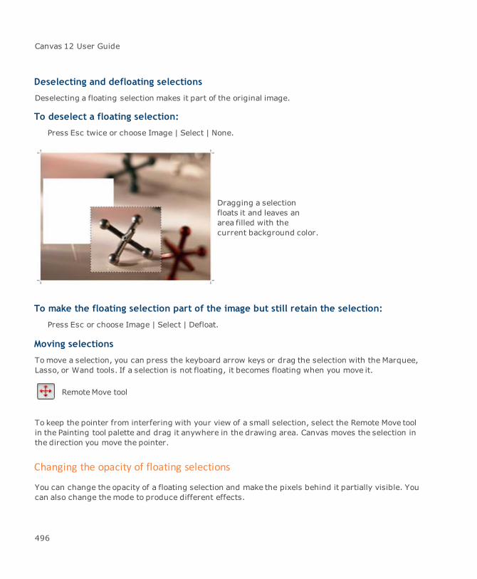
Canvas 12 User Guide
Deselecting and defloating selections
Deselecting a floating selection makes it part of the original image.
To deselect a floating selection:
Press Esc twice or choose Image | Select | None.
Dragging a selectionfloats it and leaves anarea filled with thecurrent background color.
To make the floating selection part of the image but still retain the selection:
Press Esc or choose Image | Select | Defloat.
Moving selections
Tomove a selection, you can press the keyboard arrow keys or drag the selection with the Marquee,Lasso, or Wand tools. If a selection is not floating, it becomes floating when you move it.
RemoteMove tool
To keep the pointer from interfering with your view of a small selection, select the Remote Move toolin the Painting tool palette and drag it anywhere in the drawing area. Canvas moves the selection inthe direction you move the pointer.
Changing the opacity of floating selections
You can change the opacity of a floating selection and make the pixels behind it partially visible. Youcan also change themode to produce different effects.
496
Chapter 5: Painting And Image Editing
You cannot make selections partially transparent in Indexed or Black & White image modes.
To change the opacity of floating selections:
1. With a paint object in edit mode, select part of the image.
2. Click on the Background color icon in the Toolbox.
3. Select a color to use behind the floating selection. This color will start to appear when youmake the selection transparent.
To use the Floating Opacity slider in the Channels palette to lighten a floatingselection: Fill behind the selection with white or a light color.
4. Hold down the Ctrl key and choose Image | Select | Float. Canvas floats the selection and fillsbehind it with the background color.
5. Choose Image | Show Channels to open the Channels palette. Set the Floating Opacity valueto less than 100 percent to make the selection become transparent and reveal thebackground color behind the selection.
6. To change themode, choose a new mode from the Modemenu.
Modifying selections
You can use the Expand, Contract, Smooth, and Border commands tomodify selections in images.
These commands make it easy to fine-tune a selection by expanding or contracting the selectionborder by a specified number of pixels, or by adding or subtracting pixels based on color.
Expanding a selection
You can expand a selection by adding a specified number of pixels to the selection border.
To modify an active selection:
Choose Image | Select | Modify | Expand. Type a value in the Radius text box and click OK. Canvasadds the specified area to the selection.
Contracting a selection
You can shrink a selection by subtracting a specified number of pixels from the selection border.
497
Canvas 12 User Guide
To modify an active selection:
Choose Image | Select | Modify | Contract. Type a value in the text box and then click OK. Canvassubtracts the specified area from the selection and the dashed border contracts.
Smoothing a selection
The Smooth command is useful after you havemade a color-based selection that has left stray pixelsinside or outside of the selected area. The Smooth command includes or eliminates the stray pixels toeven out the selection. The value you type in the text box determines which pixels will be included orexcluded in the selection at the border.
To modify an active selection:
Choose Image | Select | Modify | Smooth. Type a value in the text box and then click OK. Canvasadds or subtracts pixels to the perimeter of the selection based on the radius number of pixelsyou specified.
Bordering a selection
After you define a selection, you can select the area at the border of the selection by specifying anoffset in pixels from the selection edge.
To modify an active selection:
Choose Image | Select | Modify | Border. Type a value in the text box and click OK. Two dashedborders indicate the selected border.
Once you make a selection, you can use the Grow command or the Similar command to expand theselection to include similar colors.
Creating objects from selections
You can make new paint objects from image selections with the New Image from Selection command.This command converts a selection in an image into a new paint object in the same position on theimage you are editing. This can be useful for “layering” image compositions.
The result of New Image fromSelection is similar to moving a selection to a transparent “layer,” aprocedure used in some image editing programs. In Canvas you can use separate transparent paintobjects to create “layered” image compositions.
This operation doesn’t affect the Clipboard contents.
498
Chapter 5: Painting And Image Editing
To create a paint object from a selection:
With a selection in an image, choose New Image fromSelection in the context menu. To displaythe context menu, right-click within the selection.
New images from selections and floating selections
When you choose New Image from Selection, Canvas removes the selection from the image ordeselects the selection in the image. The selection appears as a new paint object in the samelocation.
Whether a selection is removed from an image depends on whether the selection is floating. Theopacity of the resulting object also differs for floating and non-floating selections.
If a selection is not floating, Canvas deselects it but otherwise doesn’t change the original imagewhen you create an object from the selection. The selected pixels keep their original opacity in thenew object.
If a selection is floating, Canvas removes the selection. The effect is the same as deleting a selection:the background color replaces the selected pixels, or, if the object has a visibility mask, a clearbackground replaces the selected pixels. In the new object, the pixels are opaque, regardless of theiroriginal opacity.
Clear backgrounds in new paint objects
A paint object created from a selection always has a clear, rather than opaque background, and avisibility mask.
Paint objects are rectangular. If a selection is not rectangular, Canvas places the selection on a clearbackground. This is why creating a paint object from a selection is like transferring the selection to aclear overlay on the original image.
If you select Preserve Visibility in the Channels palette, a visibility mask preserves the transparencyof all pixels in the image. You can paint or use filters without affecting clear areas.
If Preserve Visibility is not selected, you can erase to a clear background and affect all pixels bypainting and editing.
Converting selections to paths
Canvas can trace a selection in an image to create a path (vector object) from the selection border.The Selection to Path command traces the active image selection border using the settings youspecify. This is useful if you want to convert a selection border to a vector object that can be used asa clipping path, for example.
499
Canvas 12 User Guide
The accuracy of a path made from a selection depends on the settings you specify and the complexityof the selection border. A very complex selection border can result in a path with hundreds of anchorpoints, which can cause problems in printing and other operations.
Paths created from selections have no fill ink, black pen ink, and the current stroke setting.
To convert a selection to a path:
1. Make a selection in an image.
2. Choose Image | Selection to Path.
3. Choose the settings you want and click OK (see "Selection to Path options" on page 500). Theselection in the image is deselected and a new vector object (or group of vector objects)appears in front of the paint object.
Selection to Path options
Mask Set Threshold If a selection edge is feathered, this value defines the edge of theselection for tracing based on selection mask opacity. Enter a value from1 (nearly transparent) to 255 (opaque). These values correspond to thelightness of pixels for a selection saved as a mask in a channel.
Pixels in the selection mask that are more opaque (lighter) than thethreshold value are treated as opaque and part of the selection. Pixelsthat are less opaque (darker) than the threshold value are treated astransparent and outside the selection. At a threshold of 1, the entirefeathered edge will be part of the selection. At 255, only the completelyopaque part of the selection will be included.
If a selection is not feathered, this value has no effect.
Curves/Polygons ChooseCurves to create paths with smooth anchor points and curvesegments as appropriate. Choose Polygons to create paths with straightsegments only. The Curves option can result in smoother paths withfewer anchor points when the selection border has curves.
Loose /Tight Drag the slider to set the tolerance for tracing irregularities in theselection border. Loose follows the selection border less precisely (moresmoothly) and creates fewer anchor points. Tight follows the selectionborder more precisely (less smoothly) and creates more anchor points.
Round /Sharp Drag the slider to set the tolerance for tracing corners in the selectionborder. Round creates rounder corners, Sharp creates sharper corners.
500

Chapter 5: Painting And Image Editing
Saving and loading selections in channels
When you havemade a selection in an image, you can create an alpha channel from the selection. Analpha channel preserves the shape and opacity of a selection, so you can use it to make the sameselection in the image again.
You can think of an alpha channel as a mask that selects some areas and protects other areas frompainting and image editing. Because alpha channels make precise selections of varying intensities,alpha channels let you control which areas in an image will be affected by painting tools and filters,and the intensity of the effects.
When you view an alpha channel, you see a grayscale image. When the channel is made from aselection, it contains white areas representing fully selected pixels, black areas representingunselected pixels, and gray areas representing pixels that are partially selected, with the graylightness values corresponding to the selection opacity.
This section describes how to save a selection in a channel, and how to load a channel to make aselection in an image, using dialog boxes. You can also use shortcuts in the Channels palette, asdescribed under "Channels palette options" on page 504.
To save a selection in a channel:
1. With an active selection in an image, choose Image | Select | Save.
2. In the Operation area of the Save Selection dialog box, select New Channel and click OK.
You can also click the Selection button in the Channels palette to save the current selection in a newchannel.
To load a selection from a channel:
1. With a paint object in edit mode, choose Image | Select | Load.
2. In the Load Selection dialog box, choose a channel name in the Channel pop-up menu. Toinvert the selection, click Invert.
3. Choose an option in the Operation area and click OK.
501

Canvas 12 User Guide
Option Result
New Selection Removes any current selections and creates a new selection
Add to Selection Preserves the current selection and selects additional pixels based onthe channel
Subtract fromSelection
Removes pixels from the current selection based on the channel
Intersect withSelection
Creates a new selection composed of pixels that appear in both thecurrent selection and the channel you are loading
Preserving channels in exported images
Canvas image channels are compatible with the alpha channels used in other image-editingprograms, including Adobe Photoshop. However, you must use the correct procedure to preservealpha channels when you export an image into Photoshop format.
If you want to export an image into Photoshop format and preserve the image’s alpha channels, besure to choose Image | Export, rather than the Save As command.
If you use the Save As command and choose Photoshop format, the resulting file will not contain thealpha channels associated with the image.
To export an image with alpha channels:
1. Select the paint object in the Canvas document.
2. Choose Image | Export | Photoshop.
3. In the dialog box, specify a location to save the file, type a file name, and click Save to exportthe selected image as a Photoshop file.
Understanding image channels
Canvas uses up to 24 channels to store the digital information that makes up the image in a paintobject.
There are three types of channels: color or image channels, alpha channels, and channel masks. Allimages have at least one channel. An image can also contain one or more alpha channels and a singlechannel mask, if you create them.
The Channels palette displays the channels of an image. Whenever an image is in edit mode, you canuse the Channels palette to select and edit channels.
502
Chapter 5: Painting And Image Editing
To display the Channels palette:
Choose Image | Show Channels.
Vector objects and text objects do not have color or image channels. However, you can create achannel mask for any object. If an object has a channel mask, you can place the channel mask in editmode, and use the Channels palette to work with the channel mask and create alpha channels. Alphachannels are stored with an object as long as the object has a channel mask.
Color channels
Images in RGB Color, CMYK Color, and LAB Color mode have separate color channels. A color channelstores one component of the image; e.g., in CMYK Color mode, the Magenta channel stores themagenta parts of the image. This channel contains the image that would appear on the magenta plateif you output color separations.
A paint object’s image mode determines the number of color channels. RGB Color images have Red,Green, and Blue color channels. CMYK Color images have Cyan, Magenta, Yellow, and Black channels.LAB Color images have Lightness, A, and B channels.
In the Channels palette, a composite channel appears above the color channels. The compositechannel represents the complete image — the composite of the image’s color channels. Thecomposite channel is labeled RGB, CMYK, or LAB, depending on the image mode.
Other image modes do not have separate color channels. Images in Black & White, Duotone, Indexed,and Grayscale mode have a single image channel.
Alpha channels
Alpha channels are channels you can use to store and edit selections in any image. Because alphachannels are used for image selections, they are also referred to as “selection masks.”
After you make a selection in an image, you can save the selection in an alpha channel. Later, you canload the channel to make the same selection.
An alpha channel is a grayscale channel that is the same size and resolution as the paint object inwhich it is stored. Pixels in alpha channels can range in lightness from 0 (black) to 255 (white). Thelightness levels of pixels in an alpha channel correspond to a range of selection levels.
Black pixels in an alpha channel correspond to masked, or non-selected, pixels in an image. Whitepixels correspond to selected pixels. Gray pixels correspond to various levels of selection, withlighter grays corresponding to greater selection than darker grays.
If you want black pixels to correspond to selected, rather than masked pixels, click SelectedArea in the New Channel or Channel Options dialog box.
503
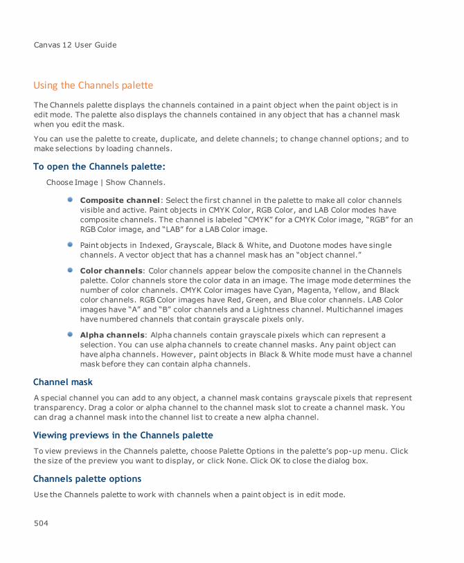
Canvas 12 User Guide
Using the Channels palette
The Channels palette displays the channels contained in a paint object when the paint object is inedit mode. The palette also displays the channels contained in any object that has a channel maskwhen you edit the mask.
You can use the palette to create, duplicate, and delete channels; to change channel options; and tomake selections by loading channels.
To open the Channels palette:
Choose Image | Show Channels.
Composite channel: Select the first channel in the palette to make all color channelsvisible and active. Paint objects in CMYK Color, RGB Color, and LAB Color modes havecomposite channels. The channel is labeled “CMYK” for a CMYK Color image, “RGB” for anRGB Color image, and “LAB” for a LAB Color image.
Paint objects in Indexed, Grayscale, Black & White, and Duotone modes have singlechannels. A vector object that has a channel mask has an “object channel.”
Color channels: Color channels appear below the composite channel in the Channelspalette. Color channels store the color data in an image. The image mode determines thenumber of color channels. CMYK Color images have Cyan, Magenta, Yellow, and Blackcolor channels. RGB Color images have Red, Green, and Blue color channels. LAB Colorimages have “A” and “B” color channels and a Lightness channel. Multichannel imageshave numbered channels that contain grayscale pixels only.
Alpha channels: Alpha channels contain grayscale pixels which can represent aselection. You can use alpha channels to create channel masks. Any paint object canhave alpha channels. However, paint objects in Black & White modemust have a channelmask before they can contain alpha channels.
Channel mask
A special channel you can add to any object, a channel mask contains grayscale pixels that representtransparency. Drag a color or alpha channel to the channel mask slot to create a channel mask. Youcan drag a channel mask into the channel list to create a new alpha channel.
Viewing previews in the Channels palette
To view previews in the Channels palette, choose Palette Options in the palette’s pop-up menu. Clickthe size of the preview you want to display, or click None. Click OK to close the dialog box.
Channels palette options
Use the Channels palette to work with channels when a paint object is in edit mode.
504
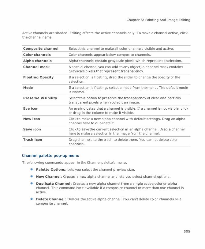
Chapter 5: Painting And Image Editing
Active channels are shaded. Editing affects the active channels only. Tomake a channel active, clickthe channel name.
Composite channel Select this channel to make all color channels visible and active.
Color channels Color channels appear below composite channels.
Alpha channels Alpha channels contain grayscale pixels which represent a selection.
Channel mask A special channel you can add to any object, a channel mask containsgrayscale pixels that represent transparency.
Floating Opacity If a selection is floating, drag the slider to change the opacity of theselection.
Mode If a selection is floating, select a mode from themenu. The default modeis Normal.
Preserve Visibility Select this option to preserve the transparency of clear and partiallytransparent pixels when you edit an image.
Eye icon An eye indicates that a channel is visible. If a channel is not visible, clickor drag in the column to make it visible.
New icon Click to make a new alpha channel with default settings. Drag an alphachannel here to duplicate it.
Save icon Click to save the current selection in an alpha channel. Drag a channelhere to make a selection in the image from the channel.
Trash icon Drag channels to the trash to delete them. You cannot delete colorchannels.
Channel palette pop-up menu
The following commands appear in the Channel palette’s menu.
Palette Options: Lets you select the channel preview size.
New Channel: Creates a new alpha channel and lets you select channel options.
Duplicate Channel: Creates a new alpha channel from a single active color or alphachannel. This command isn’t available if a composite channel or more than one channel isactive.
Delete Channel: Deletes the active alpha channel. You can’t delete color channels or acomposite channel.
505
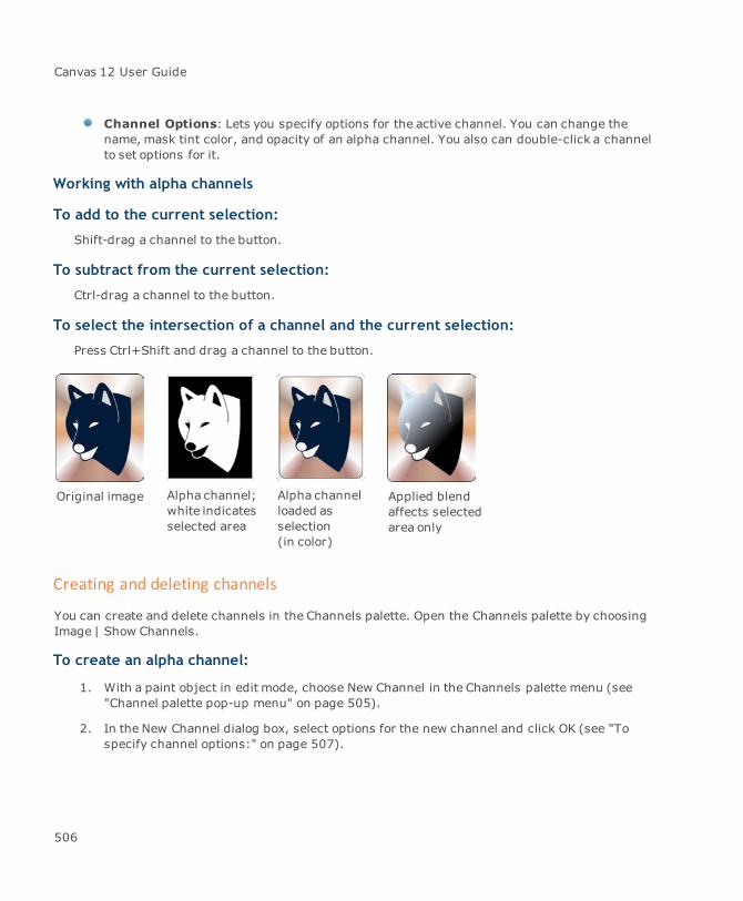
Canvas 12 User Guide
Channel Options: Lets you specify options for the active channel. You can change thename, mask tint color, and opacity of an alpha channel. You also can double-click a channelto set options for it.
Working with alpha channels
To add to the current selection:
Shift-drag a channel to the button.
To subtract from the current selection:
Ctrl-drag a channel to the button.
To select the intersection of a channel and the current selection:
Press Ctrl+Shift and drag a channel to the button.
Original image Alpha channel;white indicatesselected area
Alpha channelloaded asselection(in color)
Applied blendaffects selectedarea only
Creating and deleting channels
You can create and delete channels in the Channels palette. Open the Channels palette by choosingImage | Show Channels.
To create an alpha channel:
1. With a paint object in edit mode, choose New Channel in the Channels palette menu (see"Channel palette pop-up menu" on page 505).
2. In the New Channel dialog box, select options for the new channel and click OK (see "Tospecify channel options:" on page 507).
506
Chapter 5: Painting And Image Editing
Deleting alpha channels
Although Canvas can store up to 24 channels in an image, you might want to delete unnecessaryones to savememory and disk space. You can delete alpha channels and channel masks, but youcannot delete color channels.
To delete an alpha channel:
With an object in image edit mode, drag the alpha channel you want to delete to the trash can iconat the bottom of the Channels palette.
Customizing alpha channels
You can change an alpha channel’s name, color indication, and mask tint opacity in the ChannelOptions dialog box. By default, Canvas numbers alpha channels, sets themask tint opacity to 50%,and assigns a mask color.
Canvas provides themask color and opacity settings in the Channel Options dialog box asvisual aids only. These settings do not affect the original image or channel.
To specify channel options:
1. With a paint object in edit mode, choose Image | Show Channels to open the Channelspalette.
2. Click an alpha channel and select Channel Options in the pop-up menu, or double-click thechannel you want to edit to open the Channel Options dialog box.
3. Enter a new name in the Name field to rename the channel.
Color Indicates: These options control whether white or black pixels in the channel willselect pixels in the image when you load the channel. If you want white pixels in thechannel to indicate selected pixels, choose Masked Area. If you choose Selected Area, thenormal operation of the channel will be inverted, so that black pixels in the channel willselect pixels when the channel is loaded. If you use this option, keep in mind that thechannel will make selections that are the inverse of normal channel selections.
To change the mask tint color for the channel: Select a color from the Color pop-upmenu. Canvas displays the tint when an alpha channel and at least one other channel arevisible.
To change the opacity of the tint color: Enter a value from 1 to 100% in the Opacitytext box.
4. Click OK after entering the settings you want.
507
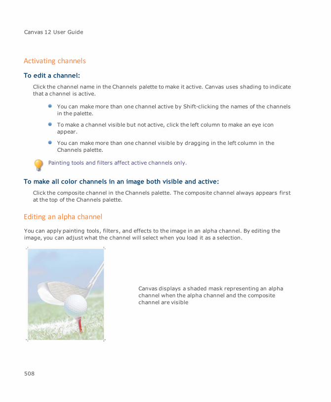
Canvas 12 User Guide
Activating channels
To edit a channel:
Click the channel name in the Channels palette tomake it active. Canvas uses shading to indicatethat a channel is active.
You can makemore than one channel active by Shift-clicking the names of the channelsin the palette.
Tomake a channel visible but not active, click the left column tomake an eye iconappear.
You can makemore than one channel visible by dragging in the left column in theChannels palette.
Painting tools and filters affect active channels only.
To make all color channels in an image both visible and active:
Click the composite channel in the Channels palette. The composite channel always appears firstat the top of the Channels palette.
Editing an alpha channel
You can apply painting tools, filters, and effects to the image in an alpha channel. By editing theimage, you can adjust what the channel will select when you load it as a selection.
Canvas displays a shaded mask representing an alphachannel when the alpha channel and the compositechannel are visible
508

Chapter 5: Painting And Image Editing
1. With an image in edit mode, choose Image | Show Channels.
2. Create a new channel to use as a selection mask by doing one of the following:
If you have a selection in the image that you want to customize by editing in a channel,use the Save command to create a channel from the selection (see "To save a selection ina channel:" on page 501).
To start with a “blank” alpha channel, use the New Channel command. Be sure to choosethe Masked Area option under Color Indicates in the New Channel dialog box.
3. In the Channels palette, click the new channel to activate it. The channel appears shaded inthe palette and the image changes to show only the channel. Now click in the left column ofthe first (composite) channel. The original image appears with a transparent colored “mask”on the image. The color mask indicates the areas that will be masked — not selected — by thechannel.
4. Use painting tools or filters to edit the image in the channel. The changes you make affect theactive channel only.
5. Load the channel by choosing Image | Select | Load to make a selection with the channel.
6. Choose the channel name in the pop-up menu and then click OK.
Channel masks
Channel masks apply transparency effects to objects, including paint objects, vector objects, textobjects, and group objects. A channel mask creates transparency in proportion to the luminance ofits image.
A channel mask is a grayscale image channel. Black pixels in a channel mask produce 100%transparency in corresponding areas of themasked object. White pixels in a channel mask produce0% transparency in the masked object. Gray pixels in a channel mask produce partial transparencyin themasked object. Darker grays produce greater transparency than lighter grays.
Channel masks are powerful because they let you use painting and image-editing techniques tocreate transparency effects, and because a channel mask can be applied to any type of object. Anobject’s channel mask is the same size as its bounding box. You can detach or delete an object’schannel mask to eliminate the transparency effect.
Creating channel masks
Use the mouse, New Channel Mask command, Sprite tool, Transparency palette, or Channels palettetomake channel masks.
509

Canvas 12 User Guide
To create a channel mask:
Do one of the following:
Ctrl+double-click the object to be masked.
Select the object to be masked and choose Object | Transparency | New Channel Mask.
Click on the object with the Sprite tool.
Select the object to be masked. In the Transparency palette, choose Channel in the Maskmenu.
Canvas creates the channel mask and puts the new mask in edit mode.
If the object is a paint object, Canvas creates a channel mask with the same resolution asthe paint object.
If the object is a vector, text, or group object, the New Mask dialog box opens. Type theresolution you want for the channel mask and click OK. Canvas creates the channel maskwith the specified resolution.
To use the Channels palette:
You can create a channel mask for a paint object from an existing alpha channel or color channel.
With a paint object in edit mode, drag an alpha channel into the channel mask slot in the Channelspalette. If the slot already contains a channel mask, the channel you drag there replaces theexisting channel mask.
Editing channel masks
You can edit an object’s channel mask to change the transparency effects it produces. Generally, youcan do anything that you can when editing a color channel, alpha channel, or grayscale image: usepainting tools, filters, and image-adjustment commands, make selections, and paste selections into achannel mask.
To edit a channel mask:
Do any of the following to place a channel mask in edit mode:
Ctrl+double-click themasked object.
Select the masked object and choose Object | SpriteLayers | Edit Channel Mask.
Select the masked object and click Edit in the Transparency palette.
510

Chapter 5: Painting And Image Editing
An eye symbol in the Channels palette appears to the left of a channel that is visible. The eye symboldisappears if a channel is hidden.
When you edit a channel mask, the top channel in the palette represents the object itself. For atypical paint object this channel is labeled with the imagemode, such as RGB or CMYK. For otherobjects, the first channel is labeled “Object” (see "Transparency masks" on page 671).
The channel mask of an object in edit mode is shown in the Channel Mask slot, which is below thechannel list.
To view the channel mask only:
Click the eye symbol next to the object or composite channel at the top of the channel list. Thishides the object channel so only the channel mask is visible.
To hide the channel mask:
Click the eye symbol next to the channel mask. This hides the effect of the channel mask on theobject.
At least one channel, either the composite/object channel or the channel mask, must be visible. Ifonly one is visible, you can’t hide it by clicking its eye symbol.
To display a hidden channel:
Click to the left of the channel to restore the eye symbol.
When you edit paint objects you can edit pixels in the images by selecting channels in theChannels palette. However, when you edit other objects, you can’t select the “object”channel. You can show or hide the object channel, but you can edit pixels only in thechannel mask.
When you finish editing a channel mask, press Esc to leave edit mode.
Detaching and deleting channel masks
If an object has a channel mask, the channel mask controls the transparency of the object. You mightwant to detach or delete the channel mask to eliminate the transparency effects from the object.
When you delete a channel mask, it no longer exists in the document. When you detach a channelmask, it appears in the document as a separate grayscale paint object.
To detach a channel mask:
Select the masked object. Choose Object | SpriteLayers | Detach Mask.
511
Canvas 12 User Guide
When you detach a channel mask, Canvas removes the channel mask from the object and places it inthe document as a separate grayscale paint object. If the channel mask was detached from a vectorobject, the resulting paint object will contain any alpha channels that were contained in the vectorobject.
To delete a channel mask:
1. Select the masked object.
2. In the Transparency palette, choose None in the Mask pop-up menu.
Deleting the channel mask of a vector, text, or group object also deletes any alpha channelsthat were contained in the object. Also, if you ungroup a group object that has a channelmask, Canvas deletes the channel mask.
You can delete a paint object’s channel mask when the paint object is in edit mode by dragging thechannel mask to the trash can icon at the bottom of the Channels palette.
Transparency effects with channel masks
Channel masks let you add transparency to images without altering them permanently. A channelmask creates transparency without changing any pixels in an image. You can remove a channel maskto eliminate the transparency effect at any time.
To make an image transparent:
Tomake parts of an image transparent—to eliminate the background in a photograph, for example—you can create a channel mask from a selection. This procedure explains how to transfer a selectioninto a channel mask to make selected areas transparent.
1. Choose Image | Show Channels to open the Channels palette. Double-click the paint object toput it into edit mode. You can use various techniques to select the areas you want to betransparent:
You can click the Wand tool to select similar colors throughout the image. If a photographhas a colored background, for example, click the background to select it. You can also usethe Color Range command tomake a selection.
To soften the edges of the selection, you can use the Image | Select | Feather command.
2. Click the Selection button in the Channels palette to save the selection in a new alphachannel. In the alpha channel, white pixels correspond to the selection. (A partial selectionproduces gray pixels in the channel). Black pixels in the channel correspond to unselected
512
Chapter 5: Painting And Image Editing
areas of the image. To create transparent areas from the selection, you need to invert thechannel.
3. Press Esc to deselect the selection in the image. Then, click the alpha channel in theChannels palette tomake it active.
4. Choose Image | Adjust | Invert. This reverses the white and black areas in the channel.
5. Drag the alpha channel into the Channel Mask slot in the Channels palette. Black areas in thechannel mask produce transparent areas in the image. White areas in the channel maskproduce opaque areas in the image.
6. Press Esc to exit image edit mode. The selection you made is now transparent. If you placethe paint object on a background in your document, the background will be visible throughthe transparent areas of the image.
To create a transparency fade:
Create a transparent fade effect using a channel mask. This procedure explains how to create a blendin an alpha channel, and then create a channel mask to make an image fade to transparency.
1. Choose Image | Show Channels to open the Channels palette. Double-click a paint object toput it in edit mode.
2. Click the New Channel button in the Channels palette. A new alpha channel appears in thepalette. Click the channel to make it active.
3. Select the Blend tool. With the foreground color set to white and the background color set toblack, drag vertically from top to bottom in the channel. This creates a blend from white toblack.
You can change the distance that you drag the Blend tool in the channel to adjust thelength and position of the fade to transparency.
You might need to use the Blend settings in the Properties bar to select the Linear optionfor the Blend tool before you create the blend in the alpha channel. You can also set otheroptions for the Blend tool to fine-tune blends.
4. Drag the alpha channel into the channel mask slot in the Channels palette. White pixels at thetop of the channel produce opaque areas. Black pixels produce completely transparent areas.Gray pixels in the channel mask correspond with partially transparent areas in the image.
To create a channel mask by rendering:
Canvas can create a channel mask when you render a vector, group, paint, or text object.
To create themask, choose the Mask and Transparency options in the Render dialog box. Canvaswill create a channel mask that makes blank areas around and inside the objects transparent.
513
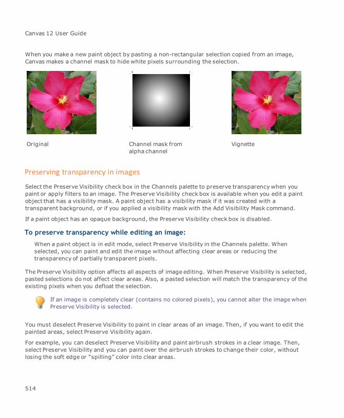
Canvas 12 User Guide
When you make a new paint object by pasting a non-rectangular selection copied from an image,Canvas makes a channel mask to hide white pixels surrounding the selection.
Original Channel mask fromalpha channel
Vignette
Preserving transparency in images
Select the Preserve Visibility check box in the Channels palette to preserve transparencywhen youpaint or apply filters to an image. The Preserve Visibility check box is available when you edit a paintobject that has a visibility mask. A paint object has a visibility mask if it was created with atransparent background, or if you applied a visibility mask with the Add Visibility Mask command.
If a paint object has an opaque background, the Preserve Visibility check box is disabled.
To preserve transparency while editing an image:
When a paint object is in edit mode, select Preserve Visibility in the Channels palette. Whenselected, you can paint and edit the image without affecting clear areas or reducing thetransparency of partially transparent pixels.
The Preserve Visibility option affects all aspects of image editing. When Preserve Visibility is selected,pasted selections do not affect clear areas. Also, a pasted selection will match the transparency of theexisting pixels when you defloat the selection.
If an image is completely clear (contains no colored pixels), you cannot alter the imagewhenPreserve Visibility is selected.
You must deselect Preserve Visibility to paint in clear areas of an image. Then, if you want to edit thepainted areas, select Preserve Visibility again.
For example, you can deselect Preserve Visibility and paint airbrush strokes in a clear image. Then,select Preserve Visibility and you can paint over the airbrush strokes to change their color, withoutlosing the soft edge or “spilling” color into clear areas.
514
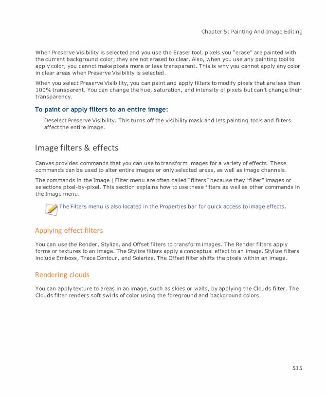
Chapter 5: Painting And Image Editing
When Preserve Visibility is selected and you use the Eraser tool, pixels you “erase” are painted withthe current background color; they are not erased to clear. Also, when you use any painting tool toapply color, you cannot make pixels more or less transparent. This is why you cannot apply any colorin clear areas when Preserve Visibility is selected.
When you select Preserve Visibility, you can paint and apply filters to modify pixels that are less than100% transparent. You can change the hue, saturation, and intensity of pixels but can’t change theirtransparency.
To paint or apply filters to an entire image:
Deselect Preserve Visibility. This turns off the visibility mask and lets painting tools and filtersaffect the entire image.
Image filters & effects
Canvas provides commands that you can use to transform images for a variety of effects. Thesecommands can be used to alter entire images or only selected areas, as well as image channels.
The commands in the Image | Filter menu are often called “filters” because they “filter” images orselections pixel-by-pixel. This section explains how to use these filters as well as other commands inthe Image menu.
The Filters menu is also located in the Properties bar for quick access to image effects.
Applying effect filters
You can use the Render, Stylize, and Offset filters to transform images. The Render filters applyforms or textures to an image. The Stylize filters apply a conceptual effect to an image. Stylize filtersinclude Emboss, Trace Contour, and Solarize. The Offset filter shifts the pixels within an image.
Rendering clouds
You can apply texture to areas in an image, such as skies or walls, by applying the Clouds filter. TheClouds filter renders soft swirls of color using the foreground and background colors.
515
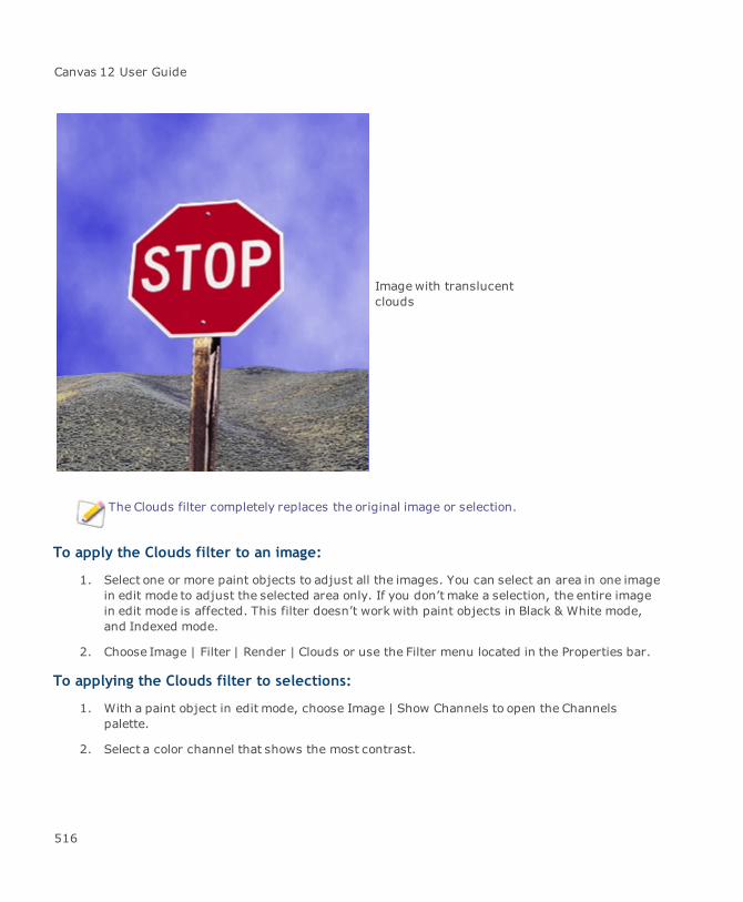
Canvas 12 User Guide
Imagewith translucentclouds
The Clouds filter completely replaces the original image or selection.
To apply the Clouds filter to an image:
1. Select one or more paint objects to adjust all the images. You can select an area in one imagein edit mode to adjust the selected area only. If you don’t make a selection, the entire imagein edit mode is affected. This filter doesn’t work with paint objects in Black & White mode,and Indexed mode.
2. Choose Image | Filter | Render | Clouds or use the Filter menu located in the Properties bar.
To applying the Clouds filter to selections:
1. With a paint object in edit mode, choose Image | Show Channels to open the Channelspalette.
2. Select a color channel that shows the most contrast.
516

Chapter 5: Painting And Image Editing
3. Drag the selected channel to the new channel button to create a copy of the channel. Thechannel copy is in black & white.
4. Select the channel copy in the Channels palette and double-click to open the Channel Optionsdialog box.
5. Enter a name for the channel copy in the dialog box.
6. With the painting tools, apply white to the areas where clouds are to appear. Apply black tothe area where clouds won’t appear.
7. Select the composite channel to make it active.
8. Choose Image | Select | Load. Select the channel copy that you edited. The white areaappears as a selection.
9. Select your background and foreground colors in the Inks palette. The colors you selectdetermine the cloud color.
10. Choose Image | Filter | Render | Clouds to affect the selected area.
Original image
517

Canvas 12 User Guide
Color channelselected
Painted channelcopy
518
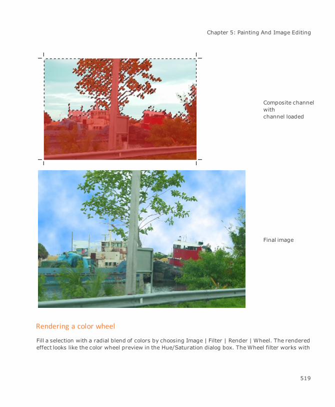
Chapter 5: Painting And Image Editing
Composite channelwithchannel loaded
Final image
Rendering a color wheel
Fill a selection with a radial blend of colors by choosing Image | Filter | Render | Wheel. The renderedeffect looks like the color wheel preview in the Hue/Saturation dialog box. TheWheel filter works with
519

Canvas 12 User Guide
paint objects in RGB Color and CMYKColor.
Unless you make a selection in the image, the Wheel filter replaces the entire image. If you want toapply a translucent wheel effect, follow the steps for the procedure "To applying the Clouds filter toselections:" on page 516, but in the seventh step, choose the Wheel command.
Embossing an image
Make an image appear raised with the Emboss filter. This filter converts low-contrast areas to grayand accentuates high-contrast areas with color (or black and white if the image is Grayscale mode)according to the placement of a theoretical light source. The Emboss filter doesn’t work with paintobjects in Black & White mode, and Indexed mode.
Original (converted to grayscale)
520
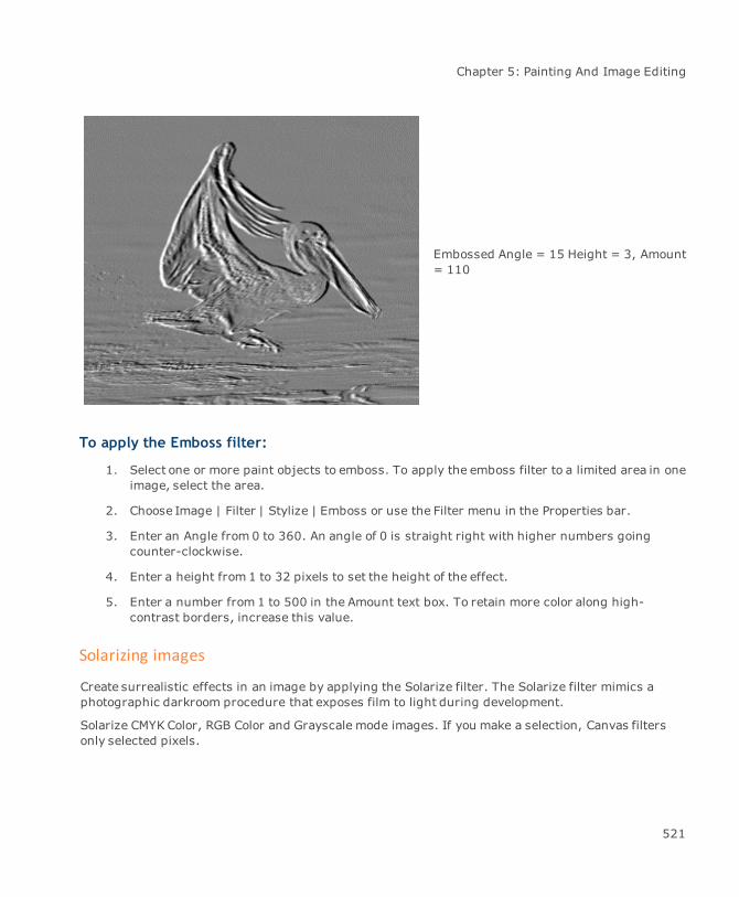
Chapter 5: Painting And Image Editing
Embossed Angle = 15 Height = 3, Amount= 110
To apply the Emboss filter:
1. Select one or more paint objects to emboss. To apply the emboss filter to a limited area in oneimage, select the area.
2. Choose Image | Filter | Stylize | Emboss or use the Filter menu in the Properties bar.
3. Enter an Angle from 0 to 360. An angle of 0 is straight right with higher numbers goingcounter-clockwise.
4. Enter a height from 1 to 32 pixels to set the height of the effect.
5. Enter a number from 1 to 500 in the Amount text box. To retain more color along high-contrast borders, increase this value.
Solarizing images
Create surrealistic effects in an image by applying the Solarize filter. The Solarize filter mimics aphotographic darkroom procedure that exposes film to light during development.
Solarize CMYK Color, RGB Color and Grayscale mode images. If you make a selection, Canvas filtersonly selected pixels.
521

Canvas 12 User Guide
To solarize an image:
1. Select one or more paint objects to solarize. To apply the Solarize filter to a limited area inone image, select the area.
2. Choose Image | Filter | Stylize | Solarize or use the Filter menu in the Properties bar.
Original
Solarized
Outlining areas based on color value
With the Trace Contour filter, you can outline image areas that border a particular color. This filtermakes color outlines if you are working with a color image, and black outlines if you are working witha Grayscale mode image. This command doesn’t work with paint objects in Black & White mode, andIndexed mode.
522
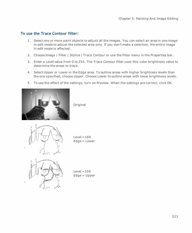
Chapter 5: Painting And Image Editing
To use the Trace Contour filter:
1. Select one or more paint objects to adjust all the images. You can select an area in one imagein edit mode to adjust the selected area only. If you don’t make a selection, the entire imagein edit mode is affected.
2. Choose Image | Filter | Stylize | Trace Contour or use the Filter menu in the Properties bar.
3. Enter a Level value from 0 to 255. The Trace Contour filter uses this color brightness value todetermine the areas to trace.
4. Select Upper or Lower in the Edge area. To outline areas with higher brightness levels thanthe one specified, choose Upper. Choose Lower to outline areas with lower brightness levels.
5. To see the effect of the settings, turn on Preview. When the settings are correct, click OK.
Original
Level =169Edge= Lower
Level =169Edge= Upper
523
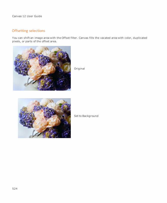
Canvas 12 User Guide
Offsetting selections
You can shift an image areawith the Offset filter. Canvas fills the vacated areawith color, duplicatedpixels, or parts of the offset area.
Original
Set to Background
524
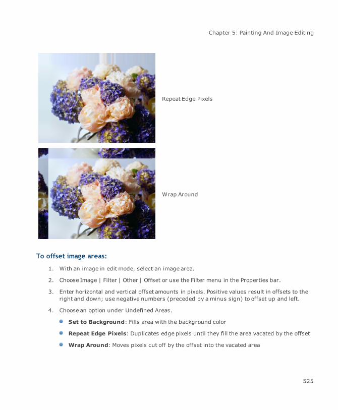
Chapter 5: Painting And Image Editing
Repeat Edge Pixels
Wrap Around
To offset image areas:
1. With an image in edit mode, select an image area.
2. Choose Image | Filter | Other | Offset or use the Filter menu in the Properties bar.
3. Enter horizontal and vertical offset amounts in pixels. Positive values result in offsets to theright and down; use negative numbers (preceded by a minus sign) to offset up and left.
4. Choose an option under Undefined Areas.
Set to Background: Fills area with the background color
Repeat Edge Pixels: Duplicates edge pixels until they fill the area vacated by the offset
Wrap Around: Moves pixels cut off by the offset into the vacated area
525
Canvas 12 User Guide
5. Turn on Preview to see the effect of the settings.
6. Click OK when the settings are correct.
Ripple effects
With the Ripple filter, create the impression of ripples in an image, like the ripples made by droppinga stone into smooth water. By varying the controls in the Ripple dialog box, produce a range of effectsin an image, from slight rippling to extreme distortion.
To apply the Ripple filter:
1. Select a paint object. To limit the effect to a particular area, select the areawhere you want toapply the filter. If you don’t make a selection, the filter affects the entire image.
2. Choose Image | Filter | Other | Ripple or use the Filter menu in the Properties bar.
3. Adjust the settings in the Ripple dialog box, and then click OK to apply the settings and closethe dialog box.
Ripple settings
Adjust the following settings in the Ripple dialog box.
Spin The Spin value controls the effect of swirling the image around its centerpoint. Type a number from -100 to 100 or drag the slider to set theamount and direction of spin. Positive numbers generate a clockwisespin; negative numbers generate a counter-clockwise spin. Largervalues (positive or negative) increase the amount of swirling. If Spin iszero, the filter creates no ripples in the image and none of the othercontrols produces an effect.
Frequency The Frequency value affects the number of “waves” created in theimage. Enter a number from 0 to 50. A high number creates more smallwaves; a low number creates fewer large waves.
Clustering The Clustering option can create interesting interference patterns incombination with some Frequency values. In general, Frequency valuesof 15 to 50 and Spin values of 25 and higher are most effective. Enter aClustering value of 0 to 30. The higher the Clustering value, themoreinterference ripples appear between the main waves.
Wave Decay TheWave Decay value softens the effect of the Frequency setting bydampening or stretching the waves away from the center of the image.The closer a wave is to the center of the image, the less it is stretched.
526

Chapter 5: Painting And Image Editing
Wave Decay creates the impression of blending the waves farthest fromthe center of the disturbance, especially when Include Corners isselected.
Enter a Wave Decay value of 0 to 100. The higher the value, the more thewaves appear stretched toward the edge of the image.
High Frequency The High Frequency option causes an approximate doubling of the effectof the Frequency setting.
Bullseye Mode Selecting Bullseye Mode leaves rings of unchanged original image areabetween the wave distortions. This creates a pattern of concentric ringslike those surrounding a bullseye. This mode can provide a means ofintegrating a recognizable version of the image with its distortion.
Include Corners This option spreads the filter’s effects to the corners of an image orselection. If Include Corners is not selected, the effects are confined to acircular area at the center of the image or selection.
Preview Select Preview to see the effects of the current settings before applyingthe filter to the image.
527
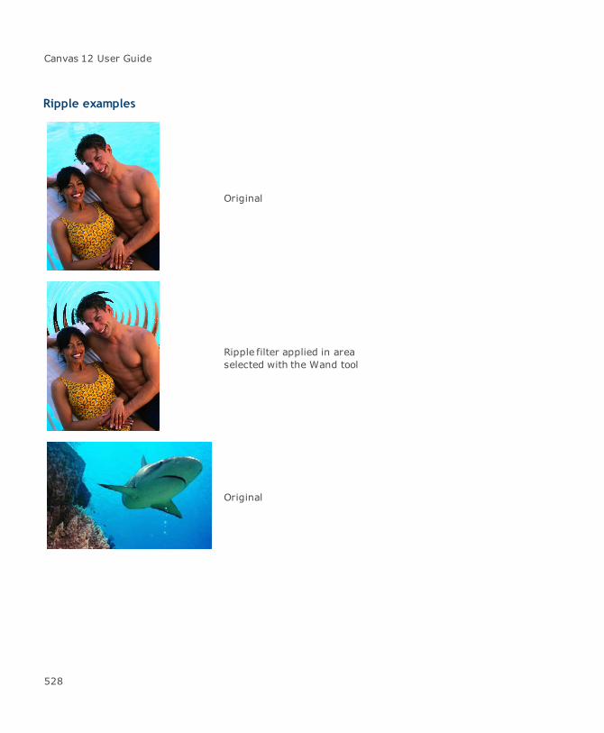
Canvas 12 User Guide
Ripple examples
Original
Ripple filter applied in areaselected with the Wand tool
Original
528
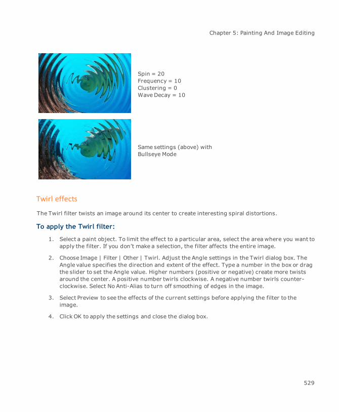
Chapter 5: Painting And Image Editing
Spin = 20Frequency = 10Clustering = 0Wave Decay = 10
Same settings (above) withBullseye Mode
Twirl effects
The Twirl filter twists an image around its center to create interesting spiral distortions.
To apply the Twirl filter:
1. Select a paint object. To limit the effect to a particular area, select the areawhere you want toapply the filter. If you don’t make a selection, the filter affects the entire image.
2. Choose Image | Filter | Other | Twirl. Adjust the Angle settings in the Twirl dialog box. TheAngle value specifies the direction and extent of the effect. Type a number in the box or dragthe slider to set the Angle value. Higher numbers (positive or negative) create more twistsaround the center. A positive number twirls clockwise. A negative number twirls counter-clockwise. Select No Anti-Alias to turn off smoothing of edges in the image.
3. Select Preview to see the effects of the current settings before applying the filter to theimage.
4. Click OK to apply the settings and close the dialog box.
529
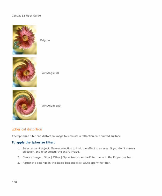
Canvas 12 User Guide
Original
Twirl Angle 90
Twirl Angle 180
Spherical distortion
The Spherize filter can distort an image to simulate a reflection on a curved surface.
To apply the Spherize filter:
1. Select a paint object. Make a selection to limit the effect to an area. If you don’t make aselection, the filter affects the entire image.
2. Choose Image | Filter | Other | Spherize or use the Filter menu in the Properties bar.
3. Adjust the settings in the dialog box and click OK to apply the filter.
530
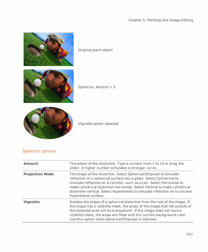
Chapter 5: Painting And Image Editing
Original paint object
Spherize: Amount = 5
Vignette option selected
Spherize options
Amount The extent of the distortion. Type a number from 1 to 10 or drag theslider. A higher number simulates a stronger curve.
Projection Mode The shape of the distortion. Select Spherical/Ellipsoid to simulatereflection on a spherical surface like a globe. Select Cylindrical tosimulate reflection on a cylinder, such as a can. Select Horizontal tomake cylindrical distortion horizontal. Select Vertical to make cylindricaldistortion vertical. Select Hyperboloid to simulate reflection on a concavehyperboloid surface.
Vignette Isolates the shape of a spherical distortion from the rest of the image. Ifthe image has a visibility mask, the areas of the image that fall outside ofthe distorted area will be transparent. If the image does not have avisibility mask, the areas are filled with the current background color.Use this option when Spherical/Ellipsoid is selected.
531

Canvas 12 User Guide
No Anti-Alias Turns off smoothing of edges in the image. Deselect this option for asmoother effect.
Preview Displays the current effect before you apply the filter.
Artistic Effects
The artistic filters, Crystallize, Lens Flare, Oil Painting, and Stained Glass, can be applied to images,text, and vector objects.
For images, access the filters by choosing Image | Filter | Artistic or use the Filter menu in theProperties bar. For text and vector objects, choose Object | SpriteEffects | Add Effect | Artistic (see"Using SpriteEffects" on page 650).
Crystallize
This filter applies a crystal- like appearance to a selected image.
BeforeCrystallize filter
532
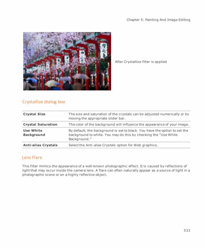
Chapter 5: Painting And Image Editing
After Crystallize filter is applied
Crystallize dialog box
Crystal Size The size and saturation of the crystals can be adjusted numerically or bymoving the appropriate slider bar.
Crystal Saturation The color of the background will influence the appearance of your image.
Use WhiteBackground
By default, the background is set to black. You have the option to set thebackground to white. You may do this by checking the “UseWhiteBackground.”
Anti-alias Crystals Select the Anti-alias Crystals option for Web graphics.
Lens Flare
This filter mimics the appearance of a well-known photographic effect. It is caused by reflections oflight that may occur inside the camera lens. A flare can often naturally appear as a source of light in aphotographic scene or on a highly reflective object.
533

Canvas 12 User Guide
Before Lens Flare
After Lens Flare
Lens Flare dialog box
Light Source Position The flare may be adjusted by using your mouse tomove the flarehighlight in the preview window.
X and Y The flare may also be moved by entering numerical values in the X or Ycoordinates box.
Zoom Adjust the slider or numerical values to adjust the zoom.
Light Intensity Adjust the slider or numerical values to adjust the light intensity.
Oil Painting
Use the Oil Painting filter to give an object the appearance of hand-painted artwork.
534
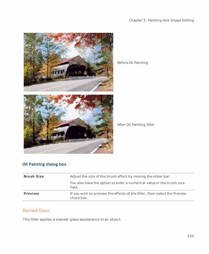
Chapter 5: Painting And Image Editing
BeforeOil Painting
After Oil Painting filter
Oil Painting dialog box
Brush Size Adjust the size of the brush effect by moving the slider bar.
You also have the option to enter a numerical value in the brush sizefield.
Preview If you wish to preview the effects of the filter, then select the Previewcheck box.
Stained Glass
This filter applies a stained-glass appearance to an object.
535
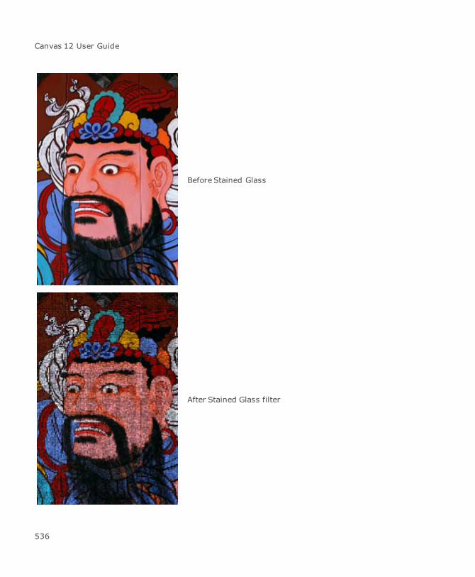
Canvas 12 User Guide
Before Stained Glass
After Stained Glass filter
536

Chapter 5: Painting And Image Editing
Stained Glass
Tile Size Adjust the effect of the filter by moving the Tile Size slider or bychanging the numerical value in the field.
Tile Shape Select either square or hexagon tile shapes.
Anti-Alias If your work is for the Web, select the Anti-alias Tiles option.
Border Thickness Adjust the size and the thickness of the space that separates each pieceof “stained glass”.
Bevel
Use the Bevel filter to give any 2D image a 3D appearance. If you are creating Web buttons and wantto give the buttons a raised appearance, apply the Bevel filter.
When working with images, you can access the Bevel filter dialog by choosing Image | Filter | Stylize| Bevel. For vector or text objects, choose Object | SpriteEffects | Add Effect | Stylize | Bevel (see"Using SpriteEffects" on page 650).
For images, ensure you apply a visibility mask to the area of the image to which you’ll applythe effect (see "Adding visibility masks to images" on page 428). If the image has atransparencymask, select the area to be beveled with either theWand tool or Marquee tools.
Before Bevel effect
After Bevel effect
537

Canvas 12 User Guide
Bevel dialog box
Direction Direction of the light source can be entered by a numeric value, sliderbar, or preview handle.
Elevation Elevation of light source can be entered by a numeric value or slider bar.
Brightness Brightness of light source can be entered by a numeric value or sliderbar.
Bevel Width Bevel width can be entered by a numeric value or slider bar.
Edge Smoothness Edge Smoothness can be entered by a numeric value or slider bar.
Corner Smoothness Corner Smoothness can be entered by a numeric value or slider bar.
Using the High Pass, Maximum, and Minimum filters
This section describes how you can create selections in alpha channels and resize bright areas incolor channels. Isolate areas in an image using the High Pass filter and Threshold command. You canuse the Maximum and Minimum filters to spread color areas you might need to trap for commercialprinting.
Isolating areas using the High Pass filter
The High Pass filter isolates high contrast edges in an image by removing low contrast detail. Thefilter makes pixels located in low contrast areas gray. In color images, the High Pass filter outlineshigh contrast edges in color. Otherwise, it outlines these edges in dark gray. This command doesn’twork with paint objects in Black & White mode, and Indexed mode.
To apply the High Pass filter:
1. Select one or more paint objects to adjust all the images. Select an area in one image in editmode to adjust the selected area only. If you don’t make a selection, the entire image in editmode is affected.
2. Choose Image | Filter | Other | High Pass or use the Filter menu in the Properties bar.
3. Enter a radius from 0.1 to 250.0 pixels.
To retain more of the original image surrounding high contrast edges:
Enter a high number. If you enter a low number, the filter makes more of the image gray.
538
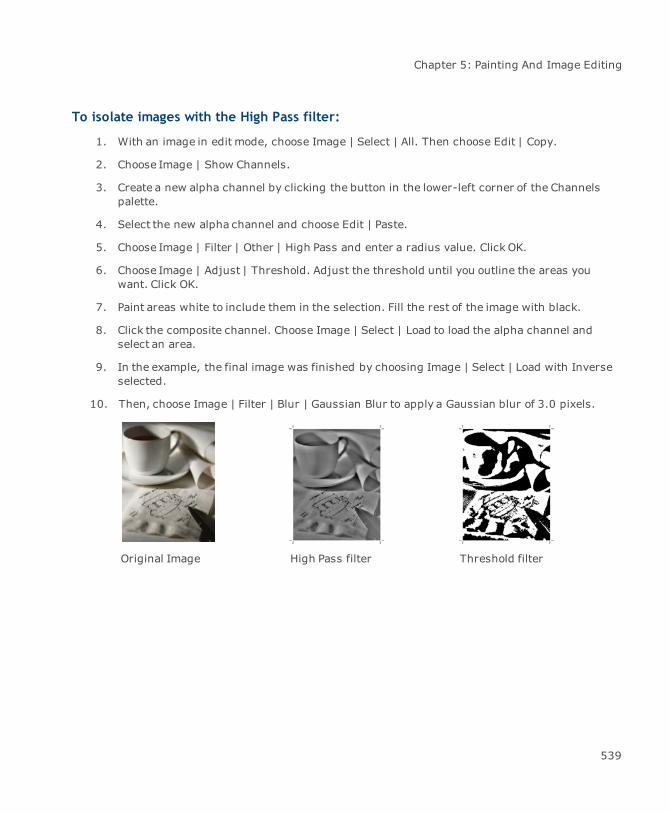
Chapter 5: Painting And Image Editing
To isolate images with the High Pass filter:
1. With an image in edit mode, choose Image | Select | All. Then choose Edit | Copy.
2. Choose Image | Show Channels.
3. Create a new alpha channel by clicking the button in the lower-left corner of the Channelspalette.
4. Select the new alpha channel and choose Edit | Paste.
5. Choose Image | Filter | Other | High Pass and enter a radius value. Click OK.
6. Choose Image | Adjust | Threshold. Adjust the threshold until you outline the areas youwant. Click OK.
7. Paint areas white to include them in the selection. Fill the rest of the image with black.
8. Click the composite channel. Choose Image | Select | Load to load the alpha channel andselect an area.
9. In the example, the final image was finished by choosing Image | Select | Load with Inverseselected.
10. Then, choose Image | Filter | Blur | Gaussian Blur to apply a Gaussian blur of 3.0 pixels.
Original Image High Pass filter Threshold filter
539

Canvas 12 User Guide
Editing with Paint tools Finished alpha channel Isolated subject
Maximizing and minimizing bright areas in an image
Increase or decrease light areas in an imagewith the Maximum and Minimum filters. The Maximumfilter adds light to shadows. The Minimum filter shrinks light areas.
To apply a choke or spread to an image manually, use the Maximum or Minimum filters in acolor channel.
When you apply these filters, Canvas compares each pixel to its neighbors within the radius youspecify, then replaces it with the lightest or darkest pixel in the group. This command doesn’t workwith paint objects in Black & Whitemode, and Indexed mode.
To use the Minimum and Maximum filters:
1. Select one or more paint objects to adjust all the images. You can select an area in one imagein edit mode to adjust the selected area only. If you don’t make a selection, the entire imagein edit mode is affected.
2. Choose Image | Filter | Other | Maximum and enter a radius from 1 to 16 pixels to maximizethe light areas in an image.
3. Choose Image | Filter | Other | Minimum and enter a radius from 1 to 16 pixels to minimizethe light areas in an image.
4. Select Preview to check the settings and then click OK.
Original Maximum 6 pixels Minimum 6 pixels
540

Chapter 5: Painting And Image Editing
Filling selections with color
The Fill command lets you quickly and uniformly fill a selection with the foreground or backgroundcolor, black, white, or gray. In addition, select an opacity level and transfer mode for application ofthe color.
To fill a selection with a color:
1. With an area of an image selected, choose Image | Filter | Other | Fill or use the Filter menuin the Properties bar.
2. In the Fill dialog box, choose a fill option from the Use pop-up menu. Tomake the colorappear transparent, set the Opacity level to less than 100%. To use a mode effect, choose anoption in the Mode pop-up menu.
3. Click OK to fill the selection.
Creating custom image filters
You can create your own special-effect and image-correcting filters using the Custom command. Youcan also save custom filters and use them in future Canvas documents.
Filters work with an image one pixel at a time. Using a mathematical formula and the color values ofpixels within a specified radius, filters assign each pixel a new color value. In a custom filter, yousupply the numbers the filter uses to calculate the new color values.
The same filter can produce different effects in other images. To get themost out of custom filters,spend time experimenting.
Original
541

Canvas 12 User Guide
Blurred image Custom filter
Embossed image Custom filter
To use Custom filters:
1. Select one or more paint objects to adjust all the images. You can select an area in one imagein edit mode to adjust the selected area only. If you don’t make a selection, the entire imagein edit mode is affected. This command doesn’t work with paint objects in Black & Whitemode, and Indexed mode.
2. Choose Image | Filter | Other | Custom.
3. In the Custom dialog box, type values from -999 to 999 in the boxes in the grid. Canvasignores blank boxes.
4. Enter a Scale value from 1 to 9,999. To retain the general appearance of the original image,the scale should equal the sum of the entries in the configuration grid. For example:
542
Chapter 5: Painting And Image Editing
Grid entries Sum Scale
2 2 1 -1 -1 3 2+2+1-1-1+3=6 6
-1574-328 -15+7+4-3+2+8=3 3
5. Enter an Offset value from -9,999 to 9,999. Positive values increase the brightness of thefinal outcome while negative values decrease the brightness.
6. Turn on the Preview option to check the filter effect. When the settings are correct, click OK.
To save a custom filter:
In the Custom dialog box, enter the filter settings and click Save. Enter a name and location for thefilter and click Save.
To load a custom filter:
In the Custom dialog box, click Load. In the directory dialog box, select the filter file and clickOpen.
Rotating images
Canvas gives you the ability of applying a soft rotate or hard rotate to your images. A soft rotate issufficient if you do not need to export the images to another format; however, if you plan onexporting your images and need them to remain rotated, then you should apply a hard rotate. A hardrotate not only rotates the image but also adds white pixels to the bounding box. Soft rotate does notadd pixels.
Anti-aliasing for rotated bitmaps
Sometimes bitmap images can lose their clarity when they are rotated. The anti-aliasing for rotatedbitmaps feature addresses this issue. If you’re rotating a bitmap and select Hard rotate for image inthe Rotate dialog box, the Anti-alias image check box becomes available. The anti-aliasing optionresults in a smoother, better quality image.
To hard rotate an image with the Rotate dialog box:
1. Choose Effects | Rotate Right or Rotate Left | Other.
2. Make sure you select Hard rotate for image to enable Anti-alias image.
543

Canvas 12 User Guide
Original bitmap beforerotation.
Original bitmap afterrotation with Anti-aliasingoff.
Bitmaps will not attain apixelated appearance afterrotation if Anti-aliasing ison.
To quickly rotate images at multiples of 90°:
1. Select the image.
2. Click on the Rotate button in the Properties bar.
3. Select a hard rotate option in themenu and enter a value of 90° (or a multiple) in the fieldand press Enter.
Distorting images
Canvas features an image effect that you can use to warp an image so it fits the bounding box of avector object.
Shape effect
To use this effect, you must first select an image and vector object.
To apply the Shape effect:
Select an image and a vector object and choose Image | Image Warp | Shape.
The Shape command is not available if more than one image or vector object is selected.
544

Chapter 5: Painting And Image Editing
Control points Click to add control points to both the source and target. Every sourcepointmust have a corresponding target point. At least 3 points must bedefined to enable the Create button.
Control points are saved in relative position to object, so if you drag orscale an object, the points will be scaled correspondingly. Save thedocument after change the control points configuration. When exitingthe session, current point configuration is automatically saved.
Segment points Click to add segments to both the source and target. Every sourcesegment must have a corresponding target segment.
Curve points Click to add curve segments to both the source and target. Every sourcecurvemust have a corresponding target curve.
End curve points Click to complete the curve.
Select all points Click to select all control points.
Delete Delete has two functions: delete current curve, if you are creating acurve, or delete selection, if any.
Save Click this button to save the control points within the source and target.
Reload Click this button to reload the saved points.
Pixel resampling Select a resampling method.
Nearest neighbor. Will remove some pixel information from your targetimage; however, if used, this setting will be the fastest.
Bilinear. Will use a bilinear interpolation algorithm duringdownsampling.
Biquadratic. Estimates the color at a pixel in the destination image byan average of 9 pixels surrounding the closest corresponding pixel inthe source image.
Bicubic. Estimates the colour at a pixel in the destination image by anaverage of 16 pixels surrounding the closest corresponding pixel in thesource image.
Polygonal. Every source pixel is mapped to a polygon in the target.
Auto. Canvas selects the most appropriatemethod for resampling.
Show Names Select this check box if you want to see labels. Use the Size menu toadjust the size of control points.
Shape Select either Circle or Square for the control point shape.
545
{ƘŀLJŜ ŜŦŦŜŎǘ ŎƻƴǘNJƻƭǎ

Canvas 12 User Guide
Opacity Adjust the transparency of the created object.
Source & Targetcolors
Select a color from the palettes to distinguish the source and target. Bydefault, the source is red and the target is green.
Create Click this button to perform the effect.
Delete Click this button to delete the created object.
Exit Click this button to leave the warp effect before or after clicking Create.
The image is the Source and thevector object is the Target.
Each Source control point has amatching Target control point.
If the vector object contains a fillink, the fill will be removed after theeffect is applied.
Envelope effect
The Envelope command lets you distort image objects, as if an image was drawn on a rubber sheetand then stretched.
546
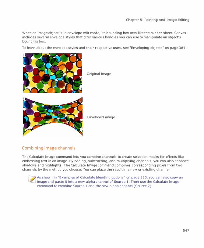
Chapter 5: Painting And Image Editing
When an image object is in envelope edit mode, its bounding box acts like the rubber sheet. Canvasincludes several envelope styles that offer various handles you can use tomanipulate an object’sbounding box.
To learn about the envelope styles and their respective uses, see "Enveloping objects" on page 384.
Original image
Enveloped image
Combining image channels
The Calculate Image command lets you combine channels to create selection masks for effects likeembossing text in an image. By adding, subtracting, and multiplying channels, you can also enhanceshadows and highlights. The Calculate Image command combines corresponding pixels from twochannels by the method you choose. You can place the result in a new or existing channel.
As shown in "Examples of Calculate blending options" on page 550, you can also copy animage and paste it into a new alpha channel of Source 1. Then use the Calculate Imagecommand to combine Source 1 and the new alpha channel (Source 2).
547
Canvas 12 User Guide
To combine channels:
1. With an image in edit mode, choose Image | Calculate.
2. Choose the first channel in the Source 1 menu. If you want to invert the channel, selectInvert. For more information, see "Inverting colors in images" on page 465.
3. In the Source 2 menu, choose the channel you want to combine with the Source 1 channel. Ifyou want to invert the channel, select Invert.
4. In the Blending area, choose an option in the Usemenu. See "Descriptions of Calculateblending options" on page 548.
5. Enter an opacity from 0 to 100 percent for Source 1. Other options are available for someBlending methods.
6. If you want to mask Source 1, select Mask in the Blending area and choose a channel in themenu. To invert themask, select Invert in the Blending area.
7. Choose the name of a destination channel or choose New in the Result menu. If you select anexisting channel, Canvas replaces the channel with the results of the Calculate Imageoperation.
8. Click OK to calculate the channel using the current settings.
Descriptions of Calculate blending options
You can select various blending methods in the Calculate Image dialog box.
Normal Places Source 1 over Source 2 at the specified opacity. 100 percentopacity replaces Source 2 with Source 1.
Multiply Creates a darker channel than the source channels. Black areas in eithersource create black areas in the resulting channel. White areas do notaffect the result.
Screen Creates a lighter channel than the source channels. White areas in eithersource create white areas in the resulting channel. Black areas do notaffect the result.
Overlay Places Source 1 over Source 2 without destroying the shadows orhighlights of Source 2.
Soft Light Lightens or darkens pixels in Source 2 depending on the brightnessvalue of the corresponding pixels in Source 1. Pixels in Source 1 that arelighter than 50% black lighten Source 2. Pixels in Source 1 that aredarker than 50% black darken Source 2.
548

Chapter 5: Painting And Image Editing
Hard Light Lightens or darkens pixels in Source 2 depending on the brightnessvalue of the corresponding pixels in Source 1. Hard Light works similarlyto Soft Light. However, black in Source 1 produces black in the resultingchannel and white produces white.
Darken Replaces pixels in Source 2 with the corresponding pixels in Source 1, ifthe pixels in Source 1 are darker.
Lighten Replaces pixels in Source 2 with the corresponding pixels in Source 1, ifthe pixels in Source 1 are lighter.
Add Creates a lighter channel than the source channels. Add is similar toScreen but usually produces a higher-contrast image.
If you select the Add option, you can enter a Scale value from 1 to 2 witha precision of three decimal places. To calculate the average brightnessvalue of two channels, choose Add and enter a Scale of 2.
You can brighten or darken the resulting channel by specifying an Offsetvalue. To lighten the overall image, enter an offset from 1 to 255. Todarken the image, enter an offset from -1 to -255.
Subtract Creates a darker channel than the source channels. Subtract is similar toMultiply. However, corresponding pixels of the same color produce blackin the resulting channel.
If you select the Subtract option, you can enter a Scale value from 1 to 2with a precision of three decimal places.
You can brighten or darken the resulting channel by specifying an Offsetvalue. To lighten the overall image, enter an offset from 1 to 255. Todarken the image, enter an offset from -1 to -255.
Difference Compares the color value of each pixel in Source 1 with thecorresponding pixel in Source 2, subtracts the darker value from thelighter, and then uses this difference in the resulting channel.
549
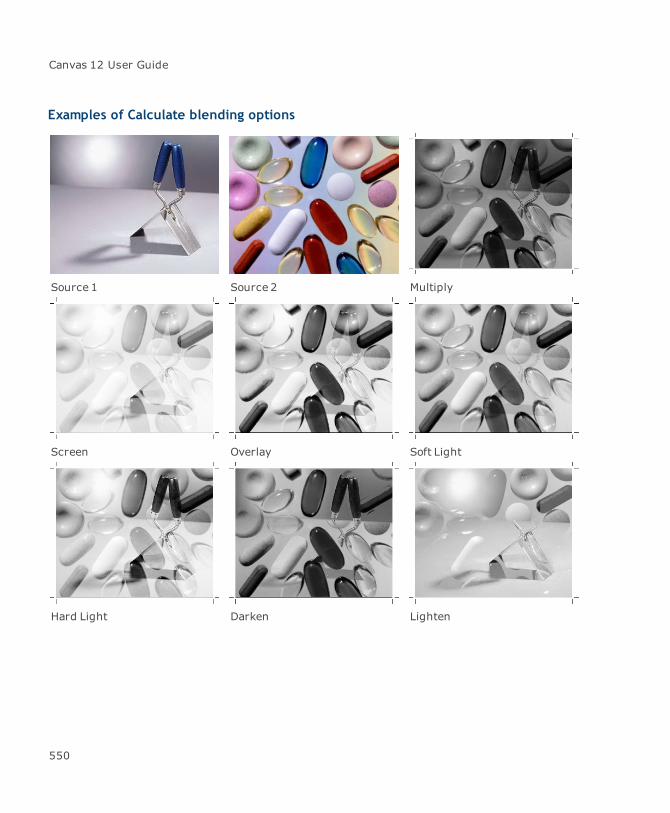
Canvas 12 User Guide
Examples of Calculate blending options
Source 1 Source 2 Multiply
Screen Overlay Soft Light
Hard Light Darken Lighten
550

Chapter 5: Painting And Image Editing
Add Subtract Difference
Image proxies
Proxies are low-resolution images you can use in Canvas documents. A proxy is a placeholder that islinked to an original image. The original high-resolution image is stored in a Canvas Image File ondisk.
Using proxies
Proxies can significantly reduce the time required to redraw the screen while you work. Also, aCanvas document that contains proxies requires much less disk storage space than one containinghigh-resolution images (although the space required to store the document and the linked image filesis approximately the same as for the document containing high-resolution images).
Proxies aremost useful for conserving time and memory when you use large, high-resolution color images in documents.
551
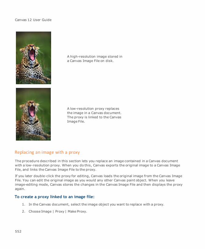
Canvas 12 User Guide
A high-resolution image stored ina Canvas Image File on disk.
A low-resolution proxy replacesthe image in a Canvas document.The proxy is linked to the CanvasImage File.
Replacing an image with a proxy
The procedure described in this section lets you replace an image contained in a Canvas documentwith a low-resolution proxy. When you do this, Canvas exports the original image to a Canvas ImageFile, and links the Canvas Image File to the proxy.
If you later double-click the proxy for editing, Canvas loads the original image from the Canvas ImageFile. You can edit the original image as you would any other Canvas paint object. When you leaveimage-editing mode, Canvas stores the changes in the Canvas Image File and then displays the proxyagain.
To create a proxy linked to an image file:
1. In the Canvas document, select the image object you want to replace with a proxy.
2. Choose Image | Proxy | Make Proxy.
552

Chapter 5: Painting And Image Editing
3. In the dialog box, select a file type and location to save the file.
4. Type a name for the image file that Canvas will create.
5. Click Save.
6. In the Make Proxy dialog box, type a value in the “Make...Times Smaller” box. The larger thisnumber, the lower the proxy resolution and the less memory required by the proxy in thedocument. The value must be from 1 to 1,000.
7. Click OK. Canvas replaces the image with a proxy and creates a file containing the originalimage on disk. The proxy is linked to the image file on disk.
If you click Cancel, Canvas closes the dialog box without replacing the original image, placing theproxy, or storing the image file on disk.
Make Proxy dialog box
You use the Make Proxy dialog box to create proxies linked to Canvas Image Files.
Original Width and height of the image.
Size of the Canvas Image File you are about to create.
Resolution of the image.
Proxy Memory required by the proxy. Thememory required changes if youenter values in the “Make...times smaller” text box.
Type the proxy reduction factor in this text box. The larger this value,the lower the proxy resolution and the less memory required by theproxy.
Location of the file on disk.
Click File to change the location that Canvas will store the CanvasImage File.
Click OK to replace the image with the proxy and create the Canvas Image file.
Final output with proxies and linked image files
To produce final high-resolution output from a document, you may need to copy the Canvasdocument from your disk to another storage media, such as a Zip disk. When you copy a documentthat contains image proxies, you need to copy the linked high resolution image file also, to be able toprint the high resolution images.
553
Canvas 12 User Guide
Make sure when you copy the documents to another disk, that you maintain the original folderstructure. It is a good idea to open the Canvas document that you copied, and check that the linkshave not been broken (see "To verify proxy links:" on page 556 for more information).
You can also replace a proxywith its linked image to eliminate the need to copy the image file. Tolearn how to do this, see "To replace a proxy with its linked image:" on page 556.
To create a proxy by acquiring a file:
You can use the Import command to create a proxy that is linked to a TIFF, JPEG, or CVI file.
You can edit acquired proxies the same as other proxy images. However, some changes you mightmake, such as adding image channels, are not supported by JPEG or TIFF files.
1. To acquire an image from a file, choose Image | Import and choose a file format in the Importdialog box.
2. In the Import dialog box, select the Acquire As Proxy option. Select the image files to importand click Import.
3. In the Proxy Info dialog box, type the proxy resolution in the “Make…Times Smaller” box. Thelarger the number, the lower the resolution of the proxy image in the document.
4. Click OK. Canvas places the proxy images in the document.
Editing proxies
When you place a proxy object in image-edit mode, Canvas loads and displays the linked image file inplace of the proxy. If the original image has changed, you see the changes.
Changes you make in image-edit mode are saved in the linked image file on disk when you exit image-edit mode. Canvas then displays an updated proxy.
Editing an image linked to a proxy is the same as editing any image in Canvas; you can use paintingtools and commands to alter pixels in the original image.
554
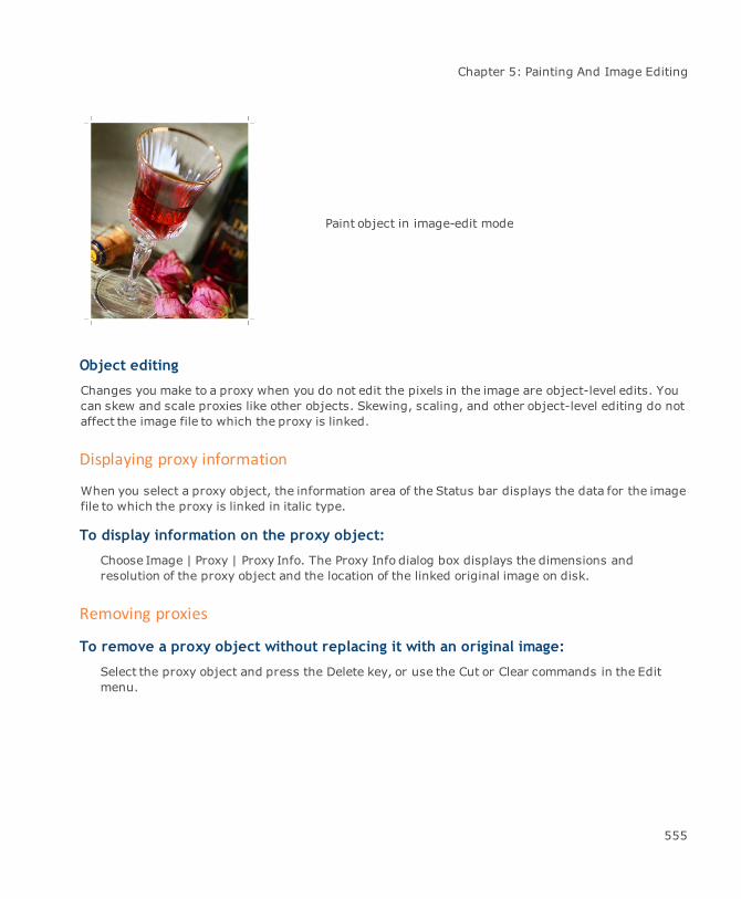
Chapter 5: Painting And Image Editing
Paint object in image-edit mode
Object editing
Changes you make to a proxy when you do not edit the pixels in the image are object-level edits. Youcan skew and scale proxies like other objects. Skewing, scaling, and other object-level editing do notaffect the image file to which the proxy is linked.
Displaying proxy information
When you select a proxy object, the information area of the Status bar displays the data for the imagefile to which the proxy is linked in italic type.
To display information on the proxy object:
Choose Image | Proxy | Proxy Info. The Proxy Info dialog box displays the dimensions andresolution of the proxy object and the location of the linked original image on disk.
Removing proxies
To remove a proxy object without replacing it with an original image:
Select the proxy object and press the Delete key, or use the Cut or Clear commands in the Editmenu.
555

Canvas 12 User Guide
To replace a proxy with its linked image:
1. Select the proxy you want to replace.
2. Choose Image | Proxy | Unlink Proxy. Canvas asks if you are sure you want to remove the linkbetween the image file and the proxy.
3. Click OK to replace the proxy and remove the link to the image file.
Maintaining proxies
If someone changes the name or location of an image file that is linked to one or more proxies, Canvasalerts you that the file could not be found when you try to edit, unlink, or update any of the proxies.
You can check proxies in a document at any time to verify that the links are valid. If Canvas detectsunlinked proxies, you can re-link them to existing image files.
You should always verify the proxy links in a document before final output. If you producefinal high-resolution output from a document with unlinked or broken proxy objects, theassociated images will not print correctly.
To verify proxy links:
Choose Image | Proxy | Check Proxies.
If Canvas finds an unlinked proxy, it displays selection handles around the proxy and centers it in thedocument window. Canvas displays a message telling you that the proxy has a problem because theimage file could not be found.
When it finds an unlinked proxy, Canvas displays the proxy’s name, if you have assigned aname to the proxy object. You can do this by typing a name in the Name field on the Data tabin the Object Specs palette (Object | Object Specs).
When Canvas tells you that a proxy has a problem, you should follow the procedure "To re-link aproxy:" on page 557. If a proxy does not have a valid link to an image file, Canvas prints the low-resolution proxy when you print the document.
If all proxies in the document have valid links to image files, Canvas displays the message: “Noproblems found.” Canvas also displays this message if the document contains no proxies.
556
Chapter 5: Painting And Image Editing
To re-link a proxy:
If you are using the Check Proxies command and Canvas finds an unlinked proxy, you can link theproxy to an image file.
1. After Canvas identifies an unlinked proxy, click Fix in themessage box.
2. In the Proxy Info dialog box, do one of the following:
Click OK to skip the proxy and continues checking other proxies.
Click Cancel to end the check.
3. Click File in the Proxy Info dialog box.
4. In the dialog box, select an image file to link to the proxy, and then click Open. Canvasreturns to the Proxy Info dialog box, which shows the path to the linked image file.
5. Click OK. Canvas closes the Proxy Info dialog box and continues to check for unlinkedproxies.
6. If Canvas finds another unlinked proxy in the current document, Canvas again selects theunlinked proxy and displays a message that the proxy has a problem. Repeat the procedurefromStep 1 above to re-link unlinked proxies that Canvas selects.
When Canvas doesn’t find any unlinked proxies, it ends the Check Proxies procedure and returns tothe document.
To change the file linked to a proxy:
Use the following procedure to link a proxy to a different image file.
1. Select the proxy object.
2. Choose Image | Proxy | Proxy Info.
3. In the Proxy Info dialog box, click File.
4. In the dialog box, select the image file you want linked to the proxy and click Open.
5. In the Proxy Info dialog box, review the new path and the name of the linked image file, thenclick OK.
Updating proxies
Use the Update Proxies command to update all proxies in a document so theymatch the image data intheir linked image file.
557
Canvas 12 User Guide
To update all proxies in the active document:
Choose Image | Proxy | Update Proxies.
To update a specific proxy:
Select the proxy object you want to update and choose Image | Proxy | Update Proxy.
Exporting Canvas Image Files
You can export any image from a Canvas document to create a Canvas Image File on disk. You canthen create proxies linked to the Canvas Image File.
This procedure creates a Canvas Image File, but does not link the image file to the document, orreplace the image with a proxy in the document.
To export an image to a Canvas Image File:
1. Select the paint object in the document and choose Image | Export | Canvas Image File.
2. In the dialog box, select a location and type a name for the image file, and then click Save.Canvas creates a Canvas Image File.
558

Chapter 6: Text And Typography

Canvas 12 User Guide
Text entry & layout
Typing text in a document
Canvas has a full range of text and typography features that let you integrate text with illustrationsand images. You can enter, format, edit, and arrange text in Canvas. You can also import text filesand use Object Linking and Embedding (OLE) to place text in documents. To help you edit and prooftext, Canvas provides spell-checking and text-searching tools.
Depending on the circumstance, use either the Text tool or Vertical Text tool to type text into adocument.
The Vertical Text tool is designed for Japanese and other languages with vertical text. For informationon the Vertical Text tool and other features for working with two-byte languages, see "Tools andoptions for two-byte and vertical text" on page 564. Remember that the Vertical Text tool does notappear unless the Enable two-byte script check box is selected on the Type page of the Text managerin the Configuration Center (see "Setting preferences" on page 97).
Text objects
All text in a Canvas document is contained in objects called text objects. Text objects can contain asingle character or line of text, or thousands of words, sentences, and paragraphs.
Dimension objects contain dimension text (see "Using the Dimensioning tools" on page358).
Text tools
The Text tool palette contains the tools you use to create text objects and edit text.
Text: Use the Text tool to create text objects and edit text.
Text Object: Use the Text Object tool to draw fixed text objects for page layouts.
Text Link: Use the Text Link tool to link text objects to create text flows.
Text Unlink: Use the Text Unlink tool to break text object links.
560

Chapter 6: Text And Typography
Link Info: Use the Link Info tool to check text flows in a document. The tool displays arrowsshowing the flow of text among linked text objects.
Text Path: Use the Path Text tool to type text along a vector path.
Text Form Field: Use the Text Form Field tool to create form text boxes.
Text Section: Use the Text Section tool to create sections and columns in the text.
Text Format Brush: Use the Text Format Brush tool to copy a text format and apply it toother text.
Vertical Text: Use the Vertical Text tool to create text objects and edit text when you areusing a double-byte language.
Vertical Text Object: Use the Vertical Text Object tool to draw fixed text objects for pagelayouts when you are using a double-byte language.
Using the Text tool
Use the Text tool to create new text objects, type text into a document, and edit text.
When you create text objects with the Text tool, you can choose whether or not to set the columnwidth before typing.
If you set the column width before typing, text wraps to the next line when it reaches theright boundary of the text object.
If you don’t set the column width before typing, the rightmargin expands indefinitely toaccommodate the amount of text you type. This is called a “caption” text object.
Whether you should set the column width before or after typing depends on the amount of text youwant to type. For short labels and callouts, you might find it easier to simply type and let Canvasadjust the right margin. However, for paragraphs or newsletter columns, it is probably easier to setthe column width before typing.
You can change the size of the text object by selecting it and dragging a selection handle.
561

Canvas 12 User Guide
To type text with the Text tool:
1. Select the Text tool from the Toolbox.
2. Do one of the following to set the location and type the text:
To enter one line of text: Click in the document. An insertion point appears where youclick. Begin typing and the right margin extends to fit the line of text that you type.
To define a text column: Drag diagonally to create a rectangular text object. Theobject’s width matters, but not its length. Canvas contracts or expands the length toaccommodate the text you type. An insertion point appears at the top of the object. Begintyping, and when you reach the rightmargin, Canvas wraps the text to the next line.
3. Press Esc to exit text-editing modewhen you finish typing. The text object remains selected.
4. Press Esc to deselect the text object or select another object. You can also click outside theobject.
Attributes of new text
When you type text, Canvas applies the current attributes and the current type format settings to thecharacters you type. For more information about changing ink and stroke attributes, see "Text inksand strokes" on page 631).
Type formatting: Canvas applies the current settings for the font, style, type size,justification (alignment), leading, and kerning to the characters you type. These settings areselected from the Text menu, the Properties bar, or with the controls in the Type palette (see"Applying text formats" on page 580).
Fill inks: Canvas applies the current fill ink, if it’s a solid color fill ink, to the text characters.
If the current fill ink is a gradient, hatch, symbol, or texture, Canvas applies 100%black to the text characters.
Pen inks: The pen ink for text you type is always 100% black, and is not visible until youapply a pen stroke to the text.
Strokes: Canvas applies no stroke to text characters you type. This means that no outlineappears on the characters, and the pen ink applied to the text is not visible because the penink appears only when an object or text has a visible stroke.
562

Chapter 6: Text And Typography
Using the Text Format Brush
Use the Text Format Brush to copy text attributes, such as font, font style, fill ink, pen ink, as well aspen stroke, so that you can apply them to other text. This tool does not copy frame ink, frame stroke,or background ink. To apply these items to text, see "To apply a background ink:" on page 633, "Toapply a frame stroke:" on page 633, and "To apply a frame ink:" on page 633.
To copy and apply text attributes:
1. Select the Text Format Brush tool.
The cursor changes to an eyedropper.
2. Click on a text object to copy the text attributes.
3. Then, click on the text object to which you want to apply the text attributes.
If you want to apply the text attributes to a single character or group of characters, drag across thecharacter or characters until they are all selected. When you release themouse, the text attributeswill be applied.
Creating text layouts
Use the Text Object tool to place text objects, or columns, in page layouts. Text objects created withthis tool keep their width and length, unlike text objects made with the Text tool, which shrink andexpand in length to fit the amount of text you type. The Text Object tool is especially useful fordesigning templates and master pages, because you can set up text columns and add type later.
If you enter text into a text object created with the Text Object tool, and there is more text than will fitin the column, an overflow indicator appears at the bottom of the text object (see "Flowing oversettext into new text columns" on page 572).
To hide the bounding boxes of text objects, choose Layout | Display | Hide Text Boxes. Toshow them again, choose Layout | Display | Show Text Boxes.
The Text Object tool doesn’t select text or place a text object in edit mode. For theseoperations, use the Text tool (see "Using the Text tool" on page 561).
563

Canvas 12 User Guide
To create an empty text object:
1. Select the Text Object tool.
When you move into the document window, the pointer is an I-beam with an arrow.
2. Drag to set the width and length of a rectangular text object.
3. Canvas deselects the Text Object tool and either selects the Selection tool or Text tool.
4. Double-click in the text object to select the Text tool. The new text object is in edit mode withan insertion point at the top of the column.
You can begin typing in the new text object immediately. Press Esc to exit text editing mode andselect the text object. Press Esc to deselect the text object.
Positioning text objects
Arrange text objects the same way you arrange other types of objects. Drag text objects with themouse, resize them by dragging a selection handle, “nudge” text objects with keyboard arrow keys,and set coordinates and dimensions in the Properties bar.
Tools and options for two-byte and vertical text
A special preference, Enable two-byte script, appears in the Typemanager of the ConfigurationCenter if your system is capable of using two-byte languages (see "Preferences for two-byte textentry" on page 123). Depending on the amount of text in your documents, activating the two-bytetext preference might slow down text editing.
You must quit and restart Canvas to activate or deactivate the two-byte text preference.
For Windows ME, 2000, and XP, the operating system supports almost any language setting,including Japanese.
When you activate the two-byte text preference, Canvas selects themetric measurement system bydefault. Select another system for measurement units by choosing Layout | Rulers (see "Setting uprulers" on page 74). The “two-byte” preference also can make available several tools and options thatlet you create vertical text objects (with or without two-byte fonts), and use an entry window fortyping two-byte characters. These tools and options are described in this section.
Available two-byte text tools and options
When the two-byte preference is active, the following items appear:
564

Chapter 6: Text And Typography
The Vertical Text tool appears in the Toolbox.
The Vertical Text Object tool appears in the Toolbox.
“Vertical” options appear in the Column Guides dialog box and the Type palette.
The Inline tab appears in the Configuration Center.
Using Vertical Text tool
The Vertical Text tool types text in vertical columns that flow from top to bottom and right to left.Create vertical columns of text in languages that use vertical text, or when you work on a publicationin which text runs across a page.
To create empty text objects, such as for a document template, to contain vertical text, use theVertical Text Object tool (see "Using Vertical Text Object tool" on page 566).
If the Vertical Text tool isn’t available because the two-byte text preference isn’t selected,you can get the same effect by rotating text 90° by choosing Effects | Rotate.
To type vertical text directly:
1. Select the Vertical Text tool.
The pointer changes to a horizontal I-beam.
2. Click in the document to place the text insertion point, and then begin typing. Since the textwill flow from top to bottom, Canvas expands the bottom of the column to fit the longest lineyou type.
3. Press Esc to exit text edit mode.
To define a column for vertical text:
1. Select the Vertical Text tool. The pointer changes to a horizontal I-beam, indicating that textwill flow from top to bottom.
2. Drag the I-beam to set the size of the column, and then begin typing. As you type, textcharacters run from top to bottom. When the text reaches the bottom edge of the column, itwraps back to the top and onto the next line to the left.
3. Press Esc to exit text edit mode.
565
Canvas 12 User Guide
Using Vertical Text Object tool
The Vertical Text Object tool lets you create empty text blocks for vertical text. Text objects createdwith the Vertical Text Object tool maintain their width and length.
To create text objects for vertical text:
1. Select the Vertical Text Object tool.
The pointer changes to a horizontal I-beam indicating that text will flow from top to bottom.
2. Drag to define the width and length of the text object. Then drag in other locations to createmore text objects, or begin typing in the new text object.
3. Press Esc to exit text edit mode.
Options for vertical text and columns
A check box labeled Vertical appears in two places: the Column Guides dialog box and Type palette.
The Vertical options described in this section are not related to the “Vertical” command thatchanges the alignment of text bound to a path.
In the Column Guides dialog box, create column guides for vertical text in Publication documents. Inthe Type palette, specify horizontal or vertical orientation for text objects.
To use vertical text column guides:
1. Choose Layout | Column Guides.
2. In the Column guides dialog box, select the Vertical check box. The column guide buttons atthe top of the dialog box change to vertical orientation.
3. Use the preset column buttons or the other options to specify guides for the number ofcolumns that you want to use.
To use preset column guides: Click one of the buttons. The first three buttons are for1, 2, and 3 text columns respectively. The last two buttons are for 2 columns with a wideand narrow column.
To set up guides for any number of columns from 1 to 12: Use the “Number ofcolumns” text box.
4. Click OK to create guides for the specified number of columns.
566

Chapter 6: Text And Typography
To use the Vertical option for text objects:
Use the Vertical option in the Type palette to set up the Text tool for vertical text and to orient textobjects to contain vertical text.
When you set the Text tool to create vertical text, lines of text that you type are vertical, withtext flowing from top to bottom and lines running from right to left. This is the same as theorientation of text within an existing text object when you apply the Vertical option.
1. Open the Type palette by double-clicking the Text tool or choosing Text | Type.
2. Do one of the following to set up the Text tool, or to change the orientation of existing textobjects:
To change the default operation of the Text tool: Make sure that no objects areselected in the document.
To change existing text objects: Select the text objects.
3. Select the Vertical check box in the Type palette and then click Apply to apply the currentsettings. Canvas applies the vertical option to the selected text objects or to the Text tool.
To change text orientation to horizontal in an object:
1. Open the Type palette.
2. Select a text object containing vertical text.
3. Deselect the Vertical check box and then click Apply.
To use vertical text in publication layouts:
1. Choose Layout | Column Guides and choose the number of columns you want to use.
2. Use the Vertical Text Object tool to click between column guides to create a text column sizedto fit the column guides.
The column extends from the point you click to the left margin of the page. If the column guides areoutside the printable area, the column text remains inside the printable area (see "Using Vertical TextObject tool" on page 566).
Creating column layouts
A section is a rectangular area that arranges text in columns. A section is made of column guides,which are non-printing lines that define the text columns and gutters (spaces between columns).
567

Canvas 12 User Guide
Sections make it easy to arrange and modify text in columns. You can place one or more sections on apage. After you place text in a section, you can change the number or the size of the columns in thesection and Canvas will adjust the text to fit.
To create text columns in a document, you could manually arrange separate text objects; however,the Section tool and column guides automate text layout. This section describes how to work with theSection tool and Column Guides to create text layouts.
A 3-column section
Creating columns
Create column layouts with the Section tool or Column Guides command (Layout | Column Guides).Use the Section tool to place multiple sections at specified locations on one or more pages. Use theColumn Guides command to define sections or change settings for existing sections.
Whether you create or modify sections with the Section tool or Column Guides command, the ColumnGuides dialog box is the control center for configuring sections.
When you create a section, the section’s column guides appear on a guide layer in the document. Bydefault, guide layers are non-printing and have a bright blue override color. Use the DocumentLayout palette to change the override color or make a guide layer printable (see "Guide layers" onpage 95).
When you add text to a section, Canvas creates a text object in each column in the section. The textobjects are placed on the current layer.
568
Chapter 6: Text And Typography
Column Guides dialog box
Section Name Canvas applies a default name when you create a section. Type a newname in the text box to change a section’s name.
Section options menu Delete sections, fit sections to a page, or fit sections to the top half orbottomhalf of a page. Choose an option from the menu.
Apply Depending on the layout, choose from This Page, All Pages, All LeftPages, Left Page, Right Page, or All Right Pages (see "Apply Tomenuoptions" on page 571).
Preset column guides Select 1, 2, or 3 columns of equal width, or 2 columns with a widercolumn on the left or right.
Number of columns Specify the number of columns; it overrides the preset column guides.Type the number of columns. The maximum number depends on thewidth of a section.
Equal widths This option makes the column widths equal to the value in the Columnbox, and makes the gutter widths equal to the value in the Gutter box.Deselect this option to set the width of a specific column.
Fixed widths This option prevents changes to the width of the columns.
Fixed gutters This option prevents changes to the width of the column gutters.
If both Fixed Gutters and Fixed Widths are selected, you can’t drag thecolumn guides in a section to adjust the widths of columns or gutters.
Vertical This option appears if “Enable two-byte script” is selected in theConfiguration Center. It creates vertical columns for text in a section.
Text Flow To change the direction of the text flow, click the button that indicatesleft to right (the arrow points right) or right to left (the arrow pointsleft).
Size If Equal Widths is not selected, set widths for columns and gutters.
Column #: Select the column by number. The widths of the selectedcolumn and gutter appear below. Columns are numbered from left toright.
Column: Enter the width of the column specified in the Column # menu.If you select a preset column option, the Column value can’t be changedunless Equal Widths is deselected first.
Gutter: Enter the width of the gutter.
569
Canvas 12 User Guide
To create sections with the Column Guides command:
1. Go to the page where you want to place a new section and choose Layout | Column Guides.
2. In the Column Guides dialog box, select a preset column arrangement or define customcolumns. In the Apply To menu, choose where to place the new section. See "Column Guidesdialog box" on page 569.
3. Click OK to create a new section with the current settings.
If the document contains no sections, Canvas creates one or more new sections, according to theApply To setting.
To create a section with the Section tool:
1. Select the Section tool.
The cursor changes to a crosshair.
2. Drag the crosshair in the document.
3. In the Column Guides dialog box, select options for the section. Select preset column guidesor specify a custom setup (see "Column Guides dialog box" on page 569).
4. Click OK to create a new section with the current settings.
Modifying sections with the Section tool
Use the Section tool to move, resize, and modify sections.
To move a section:
Drag it with the Section tool. When you move a section, text objects contained in the section movewith the section.
Unlike vector, paint, and text objects, you can’t use the Selection tool to modify a section.
To resize a section:
Do one or more of the following:
570
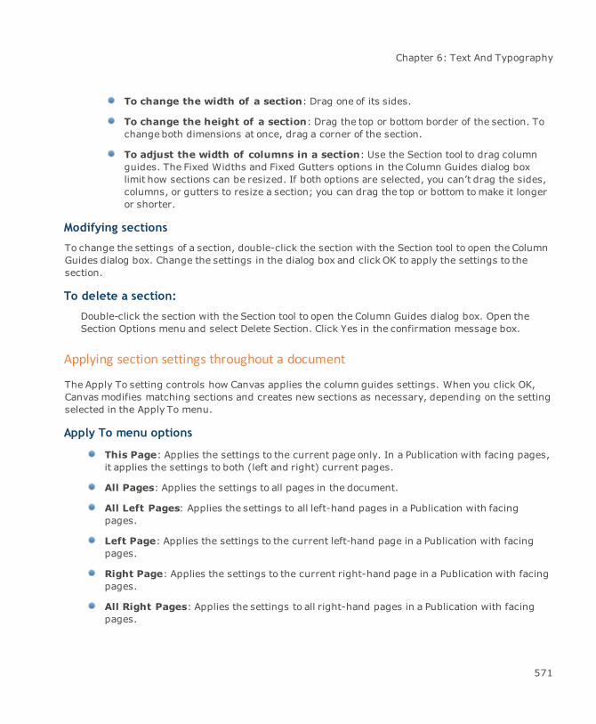
Chapter 6: Text And Typography
To change the width of a section: Drag one of its sides.
To change the height of a section: Drag the top or bottom border of the section. Tochange both dimensions at once, drag a corner of the section.
To adjust the width of columns in a section: Use the Section tool to drag columnguides. The Fixed Widths and Fixed Gutters options in the Column Guides dialog boxlimit how sections can be resized. If both options are selected, you can’t drag the sides,columns, or gutters to resize a section; you can drag the top or bottom tomake it longeror shorter.
Modifying sections
To change the settings of a section, double-click the section with the Section tool to open the ColumnGuides dialog box. Change the settings in the dialog box and click OK to apply the settings to thesection.
To delete a section:
Double-click the section with the Section tool to open the Column Guides dialog box. Open theSection Options menu and select Delete Section. Click Yes in the confirmation message box.
Applying section settings throughout a document
The Apply To setting controls how Canvas applies the column guides settings. When you click OK,Canvas modifies matching sections and creates new sections as necessary, depending on the settingselected in the Apply To menu.
Apply To menu options
This Page: Applies the settings to the current page only. In a Publication with facing pages,it applies the settings to both (left and right) current pages.
All Pages: Applies the settings to all pages in the document.
All Left Pages: Applies the settings to all left-hand pages in a Publication with facingpages.
Left Page: Applies the settings to the current left-hand page in a Publication with facingpages.
Right Page: Applies the settings to the current right-hand page in a Publication with facingpages.
All Right Pages: Applies the settings to all right-hand pages in a Publication with facingpages.
571
Canvas 12 User Guide
Displaying column guides
You can display or hide all the section column guides in a document.
To show column guides:
Choose Layout | Display | Show Guides when column guides are not displayed.
To hide column guides:
Choose Layout | Display | Hide Guides when column guides are displayed.
Typing text in a section
Use the Text tool to type text in a column in a section.
To type text in a section:
1. Select the Text tool and click at the top of the first column in the section. An insertion pointappears in the column at the height where you clicked. Canvas creates linked text objects inthe section when you click in the section with the Text tool.
2. Begin typing. Text will wrap to the next line when it reaches the column edge. If you continuetyping to the end of the column, text will flow to the next column in the section.
If a section has multiple columns, you can skip one or more columns by clicking in the section whereyou want the text flow to begin.
Flowing overset text into new text columns
You can flow text when all the text won’t fit in a text object. An indicator tells you when an object hasoverset text. If you select a text object and drag a handle to reduce its size so all the text does not fit,the overset indicator appears. You can flow text between as many columns as you want.
To flow text into the next column:
1. Click the flow symbol to change the pointer to a text flow pointer.
2. Click or drag the pointer to create a new column for the overset text.
To flow text into a column with the same margins as the original column:
Click the text flow pointer where you want the upper-left corner of the new column to appear.
To flow text into a column with different margins than the original column:
Drag the text flow pointer to specify the column width.
572

Chapter 6: Text And Typography
Resizing a text column canresult in overset text
If you click the flow symbol,the text flow pointer appears
Clicking with the flow pointercreates a new column thesame size as the original, andflows the overset text into it.
A plus sign replaces theoverset sign on the firstcolumn, indicating that textflows to another column.
Flowing text from column to column
Create text flows so that text runs from one text object to another. You can flow text to a new textobject when the text won’t all fit in an existing text object; the term “overset text” is used to refer tothe text that doesn’t fit in a text object or column.
You can also link empty text objects to create a preset text flow when you create templates for pagelayouts.
Flowing overset text to a new object
If you reduce the size of a text object, or change the text formatting, and all the text no longer fits inthe text object, you can create another text object to hold the overset text. Doing this creates a linkbetween the first and second text object, as shown in “Flowing overset text into new text columns,”above.
573
Canvas 12 User Guide
Defining text flow bars & flow symbols
A text flow bar is a solid line with a flow symbol. Text flow bars appear at the bottom of text objectswhen they contain overset text or are part of text flows. The flow symbol indicates the flow condition.
An arrow indicates that a text object contains overset text.
A plus sign indicates that text flows to another text object.
The last object in a text flow does not display a flow bar unless text is overset.
Text object hasoverset text
Text flows to anothertext object
To display text flow bars:
Choose Layout | Display | Show Text Flow Bars. To hide text flow bars, choose Layout | Display |Hide Text Flow Bars.
Linking text objects
After you create text objects with the Text tool or Text Object tool, use the Text Link tool to link theobjects and create a text flow. When text you type or insert fills one object, it flows to the next linkedtext object. The linked text object can be on another page (in a Publication document) or anotherslide (in a Presentation document). You can link columns in a chain to create articles in a multi-pagedocument such as a newsletter. The Text Link tool is especially useful for creating templates forpublications.
Text objects created with the Text tool expand as needed when text is added. However, ifyou use the Text Link tool to link objects created with the Text tool, the objects no longerexpand or contract to hold the text. Instead, they remain a fixed length, the same as objectscreated with the Text Object tool.
574
Chapter 6: Text And Typography
To link text objects:
You can use this procedure to link an object containing text or an empty text object to other textobjects.
If text boxes aren’t visible, choose Display | Show Text Boxes in the Layout menu; thismakes it easier to find and link empty text objects.
1. With the Text or Text Object tool, create at least two text objects.
2. Select the Text Link tool.
The pointer displays the number “1”.
3. Click the first text object, the object you want to flow from. The text link pointer changes tothe number “2”.
4. Click the next text object, the object you want to flow to. If you click anything but a textobject, Canvas cancels the linking operation.
5. To link another text object to the chain, repeat the linking procedure; i.e., click the objecttext will flow from, and then click the object the text will flow to.
6. Press Esc when you finish.
Unlinking text objects
Use the Text Unlink tool to break the links between text objects that have been linked into a text flow.
To unlink one text object from the next object in the flow:
1. Select the Text Unlink tool.
2. Click the first text object.
Checking text flows
The Link Info tool lets you check text flows in a document. Use the tool to display arrows showing theflow of text among linked text objects.
575
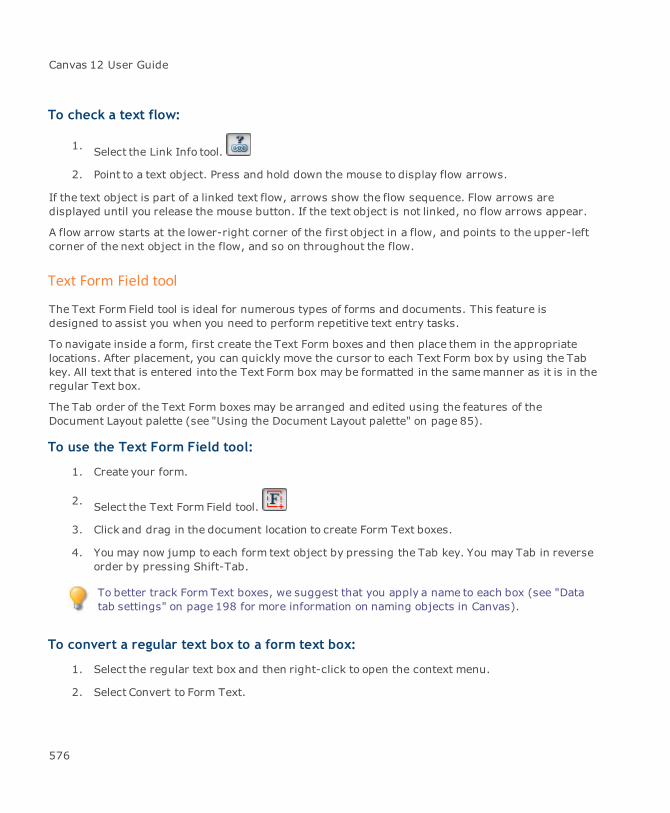
Canvas 12 User Guide
To check a text flow:
1. Select the Link Info tool.
2. Point to a text object. Press and hold down the mouse to display flow arrows.
If the text object is part of a linked text flow, arrows show the flow sequence. Flow arrows aredisplayed until you release the mouse button. If the text object is not linked, no flow arrows appear.
A flow arrow starts at the lower-right corner of the first object in a flow, and points to the upper-leftcorner of the next object in the flow, and so on throughout the flow.
Text Form Field tool
The Text Form Field tool is ideal for numerous types of forms and documents. This feature isdesigned to assist you when you need to perform repetitive text entry tasks.
To navigate inside a form, first create the Text Form boxes and then place them in the appropriatelocations. After placement, you can quickly move the cursor to each Text Form box by using the Tabkey. All text that is entered into the Text Form box may be formatted in the samemanner as it is in theregular Text box.
The Tab order of the Text Form boxes may be arranged and edited using the features of theDocument Layout palette (see "Using the Document Layout palette" on page 85).
To use the Text Form Field tool:
1. Create your form.
2. Select the Text Form Field tool.
3. Click and drag in the document location to create Form Text boxes.
4. You may now jump to each form text object by pressing the Tab key. You may Tab in reverseorder by pressing Shift-Tab.
To better track Form Text boxes, we suggest that you apply a name to each box (see "Datatab settings" on page 198 for more information on naming objects in Canvas).
To convert a regular text box to a form text box:
1. Select the regular text box and then right-click to open the context menu.
2. Select Convert to Form Text.
576
Chapter 6: Text And Typography
To convert Form Text objects to Normal text:
Right-click the Form Text box, and select Convert to Normal Text.
Formatting text
You can control all aspects of text formatting in Canvas. This section explains how to specify font,font styles, type size, character position and scaling, kerning, letter and word spacing, paragraphalignment and spacing, and hyphenation. This section also explains how to select text for formattingand how to apply format settings.
You can also save format settings as named character and paragraph styles so you can use themagain (see "Working with type styles" on page 605).
Selecting text and objects
The following section is a review of some basic selection techniques used to format text.
To select and deselect text objects:
Select text objects the sameway you select other objects in Canvas.
To select a single object: Use a Selection tool to click the text object or drag aselection rectangle around the object.
To select multiple objects: Shift-click text objects with a Selection tool. You can alsodrag a selection rectangle around all the objects you want to select.
To deselect one object: Press Shift and click the object. Other objects remainselected.
To deselect all objects: Press Esc or click an area of the screen where there are noobjects.
577

Canvas 12 User Guide
To select all text objects:
1. Select the Text tool from the Toolbox.
2. Choose Edit | Select All.
Illustration: This procedure selects all text objects on the current layer.
Publication: This procedure selects all text objects on the current page or current two-page spread.
Animation: This procedure selects all text objects on the current layer of the currentframe.
Presentation: This procedure selects all text objects on the current layer of the currentslide.
To select text within a text object:
Before you can select specific characters, words, lines, or paragraphs, the text object must be in editmode.
1. To place an object in edit mode, use one of these methods:
With a Selection tool, double-click the text object. The pointer becomes an I-beam and aninsertion point appears in the text.
Select the Text tool. The pointer becomes an I-beam. Click the I-beam within the text. Aninsertion point appears.
For bound text only, click the Path Text tool. The Path Text tool is in the Text tools palette(see "Tool palettes" on page 23).
2. Use one of the following methods to highlight the text you want to select.
To Do this
Select a continuousblock of text
Drag the I-beam over text.
Select all text betweenthe insertion point andanother location
Press the Shift key and click where you want the selection to end.
Deselect text betweenthe insertion point andanother location withinthe selection
Press the Shift key and click within the highlighted text.
578
Chapter 6: Text And Typography
To Do this
Select a word Double-click the word with the I-beam pointer.
Select a line of text Triple-click the line with the I-beam pointer.
Select all text in the textobject
Choose Edit | Select All.
Deselect all highlightedtext
Click anywhere in the text object or layout. Clicking outside theselected text object creates another text object at that location.Choosing another tool in the Toolbox ends text edit mode.
Working with linked text objects
When you link text objects so text flows from one column to another, you can select all of the text inthe flow. This lets you apply formatting changes and text styles to all the text at once, even if thecolumns are on separate pages or slides.
For information on linking text objects, see "Flowing text from column to column" on page 573.
To select all text in a flow:
1. Select the Text tool and click one of the linked text objects to place the text object in editmode and set the insertion point in the text. You can also double-click a text object with theSelection tool to enter edit mode.
2. Choose Edit | Select All. Canvas highlights all the text in the linked text objects.
3. Click outside any text object or press Esc to deselect the text.
When text is highlighted, anything you type replaces the highlighted text. If you select along text flow across several columns, and then type a single letter or press the Spacebar,all the highlighted text is erased. If this happens, choose Edit | Undo or Window | Palettes |Undos.
To apply type formatting to a text flow:
Once you select the text in a flow, you can apply formatting changes using the Properties bar,Type palette, or Text menu commands. Of course, changes that you make to selected text on otherpages or slides will not be shown until you switch to the other pages or slides.
579
Canvas 12 User Guide
Applying text formats
Canvas provides threeways to format text: the Properties bar, Text menu, and Type palette. TheType palette is also used when you create and save paragraph and character styles (see "Workingwith type styles" on page 605). The Type palette can be used to apply the paragraph and characterstyles.
You must apply or save the new settings before clicking the pointer anywhere outside theType palette. If you don’t, the settings will be lost.
When you usemenu commands or the Properties bar to apply formatting, the settings you chooseaffect the document immediately. However, with the Type palette, the settings take effect when youclick Apply. You do not have to click Apply before switching to another tab within the Type palette;Canvas remembers all changes and applies them simultaneously with one click.
To apply character formatting to existing text:
Select the characters you want to change. Choose the formatting you want to apply.
To apply paragraph formatting to existing text:
Select text in the paragraph you want to change, or place the insertion point anywhere in theparagraph. Choose the formatting you want to apply.
To establish formatting for new text objects:
When you create a new text object, Canvas applies a preset format to text you type. You can definethe preset format for new text objects. To establish or modify the preset, follow these steps:
1. Be sure you have not selected any text or text objects, and no text objects are in edit mode.To deselect all objects, press Esc twice.
2. Use one of the methods to choose formatting options. If you use the Type palette, be sure toclick the Apply button after making changes.
Canvas uses the specified settings to format new text objects that you create.
To change formatting before typing new text:
Set the format for text you are about to type without changing the preset format for new text objects.
1. Place the text object in edit mode (see "To select text within a text object:" on page 578). Thepointer should appear as an I-beam and an insertion point (a flashing vertical line) shouldappear in the text.
580
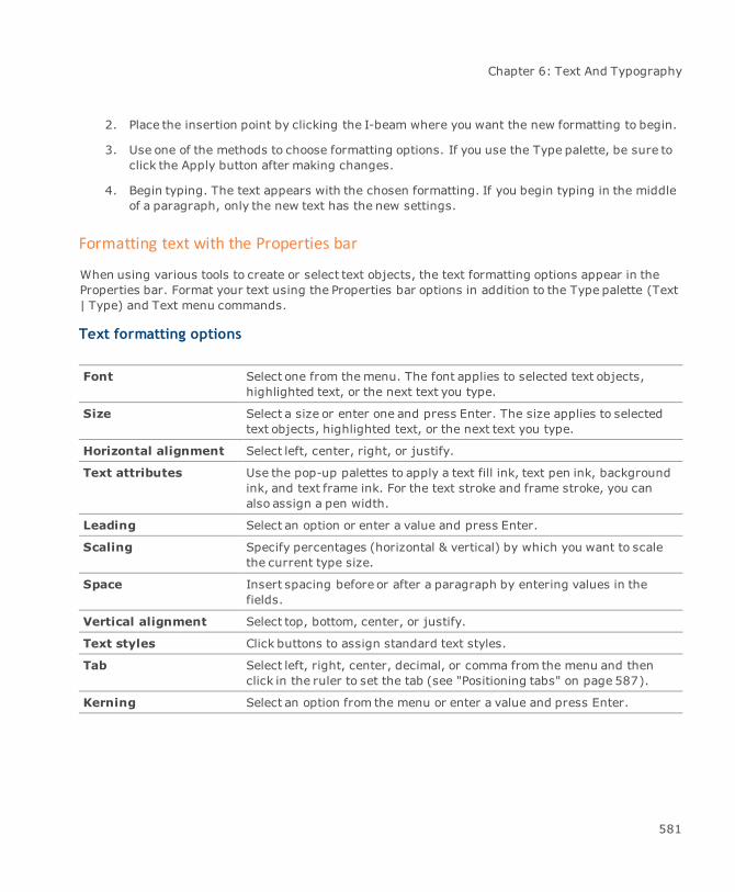
Chapter 6: Text And Typography
2. Place the insertion point by clicking the I-beam where you want the new formatting to begin.
3. Use one of the methods to choose formatting options. If you use the Type palette, be sure toclick the Apply button after making changes.
4. Begin typing. The text appears with the chosen formatting. If you begin typing in the middleof a paragraph, only the new text has the new settings.
Formatting text with the Properties bar
When using various tools to create or select text objects, the text formatting options appear in theProperties bar. Format your text using the Properties bar options in addition to the Type palette (Text| Type) and Text menu commands.
Text formatting options
Font Select one from themenu. The font applies to selected text objects,highlighted text, or the next text you type.
Size Select a size or enter one and press Enter. The size applies to selectedtext objects, highlighted text, or the next text you type.
Horizontal alignment Select left, center, right, or justify.
Text attributes Use the pop-up palettes to apply a text fill ink, text pen ink, backgroundink, and text frame ink. For the text stroke and frame stroke, you canalso assign a pen width.
Leading Select an option or enter a value and press Enter.
Scaling Specify percentages (horizontal & vertical) by which you want to scalethe current type size.
Space Insert spacing before or after a paragraph by entering values in thefields.
Vertical alignment Select top, bottom, center, or justify.
Text styles Click buttons to assign standard text styles.
Tab Select left, right, center, decimal, or comma from the menu and thenclick in the ruler to set the tab (see "Positioning tabs" on page 587).
Kerning Select an option from the menu or enter a value and press Enter.
581
Canvas 12 User Guide
Specifying fonts
Select a font using any of the methods (see "Formatting text with the Properties bar" on page 581 and"Using the Type palette" on page 589).
In Windows, the Font menu may also be set to display in single or multi-column mode.
To select a font from the Text menu:
1. Choose Text | Font. A checkmark appears next to the current font.
2. Choose a font from one of the sub-menus.
The Fonts palette
Use this palette to quickly view and apply fonts, font styles, as well as type size.
To open the palette:
ChooseWindow | Palettes | View Fonts. Use the scroll bar to view the available fonts.
To select a font: Click the font name in the list.
To apply appearance font styles: Click the style buttons.
To change type size: Enter a size in the field or select one from the menu.
To apply font styles using the Type palette:
1. ChooseWindow | Palettes | Type.
2. Click the Character tab to bring it to the front.
3. Click the Style buttons to change appearance styles.
Clicking the Plain button turns off all active appearance styles. Clicking an activeappearance style button turns the style off.
4. ChooseUpper, Lower, Normal, Title, or Small Caps in the Case menu.
5. ChooseNormal, Superscript, or Subscript in the Baseline menu. If you are applyingsuperscript or subscript, specify the distance from the baseline (in points) in the text box.Normal baseline always has an elevation of zero points.
6. Click Apply to implement the font style settings.
582

Chapter 6: Text And Typography
Tips for font installation and use
On Windows systems, Canvas uses fonts installed in the Fonts folder. You can access the Fonts foldervia the Control Panel. Use the Install New Font command in the File menu to add fonts to your system.You can also drag and drop font files or font file shortcuts to the Fonts folder. To specify that youwant to see only TrueType fonts in your programs, you can use the Options command in the Viewsmenu.
Canvas can use fonts that are properly installed as described above. If fonts that you use in anotherapplication are not available in Canvas, that application probably stores its fonts in a different locationand has its own font management capabilities.
Guidelines for choosing fonts
There are three types of fonts widely available: PostScript, TrueType, and OpenType. You can’tdistinguish the three types in the Canvas menus; however, you should be aware of the differenttypes of fonts you have, because each font is best suited for particular purposes.
PostScript Type 1 fonts are the standard for image setting. PostScript produces high-qualityprinted text. For onscreen display, however, PostScript needs screen fonts. If the screenfont for a particular point size is not installed, the text appears jagged onscreen. Tocompensate for this, you can use Adobe TypeManager (ATM) software. If a screen font isunavailable, ATM uses the PostScript printer font for both screen display and printing. Inaddition, ATM lets you print PostScript fonts to non-PostScript printers.
TrueType fonts are suitable for most desktop publishing purposes when you are printing in-house. TrueType fonts produce good quality printed text, and the onscreen appearanceclosely resembles the printed output, even when the screen font is unavailable.
OpenType fonts are the solution to font sharing across platforms. Canvas offers basicsupport for OpenType fonts, including vertical glyph substitutions in East-Asian fonts.
When typing in Canvas, all entered letters are not stored as Unicode characters, although they areexported as such in some of the export formats; e.g., HTML or SVG. However, the currentscript/code-page of the font is used (obtained from the system). Thus, the user can type in hisregional alphabet if the user has the right font that supports it; e.g., Arial-CE for a Central Europeanlanguages or MSMincho for Japanese.
Specifying type size
Choose from standard type sizes using either the Properties bar, Text menu, Type palette, or Fontspalette. To reduce or increase a font size in 1-point increments, choose Text | Size. You can alsoincrease/decrease text size in 1-point increments by using the keyboard commands Ctrl+Shift+<(Reduce) or Ctrl+Shift+> (Increase).
583

Canvas 12 User Guide
To set type size using menu commands:
1. Choose Text | Size. A checkmark appears next to the current type size.
2. Choose one of the sizes in the submenu. The size setting applies immediately.
Applying font styles
Font styles are different character types, such as bold, italic, or superscript, as well as capitalizationmodes.
Styles can be chosen and applied with either the Properties bar, Text menu, or Type palette.
Font styles can be categorized into three groups: appearance, capitalization, and baseline position.You can applymultiple appearance styles to the same text; however, you are restricted to one each ofcapitalization and baseline styles.
Appearance styles
Appearance styles include plain, bold, italic, underline, outline, shadow, small caps, andstrikethrough. Except for the Plain option, use as many of these appearances as you like on the sametext. Depending on the typeface, using certain styles might not have the desired effect, and can evenmake text appear ugly when printed; e.g., applying bold to a heavyweight typeface can makecharacters look too thick. Similarly, applying italic to an already italicized font might exaggerate theslant of the characters.
Applying the Plain setting removes other font styles that have been applied to revert text toits standard appearance.
Capitalization styles
Capitalization styles format text as uppercase, lowercase, or title (first letter of each wordcapitalized) styles. Apply one of these capitalization styles to the same text: Normal, Upper, Lower,and Title.
Baseline position
The baseline of text is the imaginary horizontal line on which characters sit. To position charactersabove (superscript) or below (subscript) the normal baseline, shift the baseline position.
Canvas does not change the type size of superscript and subscript text. Unless you reduce the typesize of shifted text, the line size increases by the amount of the baseline shift. As a result, the linespacing might change, depending on the leading setting. If you don’t want the line spacing to
584
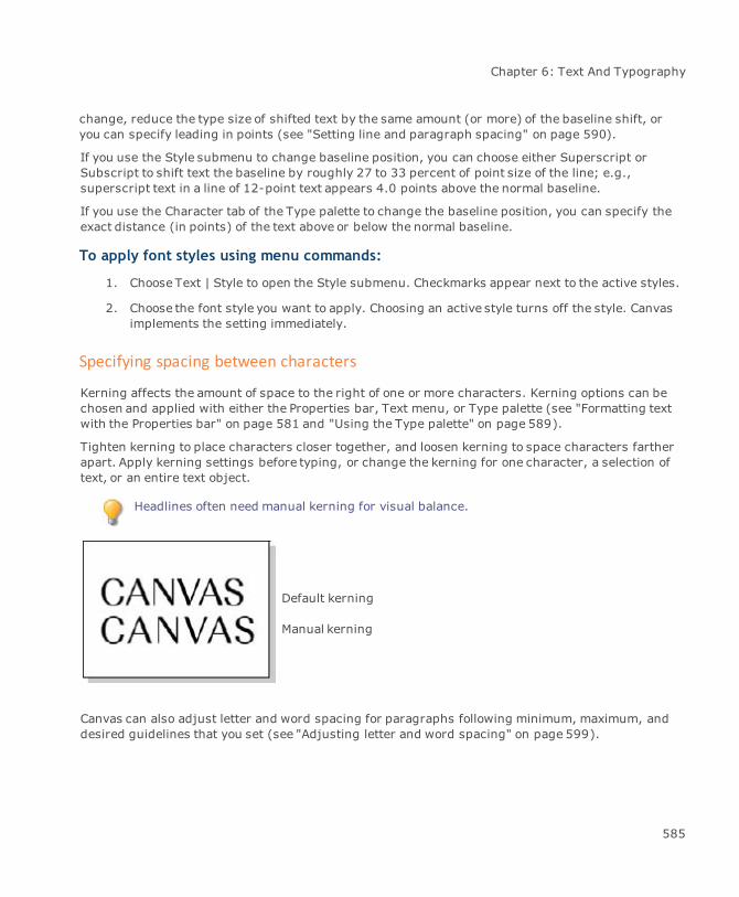
Chapter 6: Text And Typography
change, reduce the type size of shifted text by the same amount (or more) of the baseline shift, oryou can specify leading in points (see "Setting line and paragraph spacing" on page 590).
If you use the Style submenu to change baseline position, you can choose either Superscript orSubscript to shift text the baseline by roughly 27 to 33 percent of point size of the line; e.g.,superscript text in a line of 12-point text appears 4.0 points above the normal baseline.
If you use the Character tab of the Type palette to change the baseline position, you can specify theexact distance (in points) of the text above or below the normal baseline.
To apply font styles using menu commands:
1. Choose Text | Style to open the Style submenu. Checkmarks appear next to the active styles.
2. Choose the font style you want to apply. Choosing an active style turns off the style. Canvasimplements the setting immediately.
Specifying spacing between characters
Kerning affects the amount of space to the right of one or more characters. Kerning options can bechosen and applied with either the Properties bar, Text menu, or Type palette (see "Formatting textwith the Properties bar" on page 581 and "Using the Type palette" on page 589).
Tighten kerning to place characters closer together, and loosen kerning to space characters fartherapart. Apply kerning settings before typing, or change the kerning for one character, a selection oftext, or an entire text object.
Headlines often need manual kerning for visual balance.
Default kerning
Manual kerning
Canvas can also adjust letter and word spacing for paragraphs following minimum, maximum, anddesired guidelines that you set (see "Adjusting letter and word spacing" on page 599).
585

Canvas 12 User Guide
Canvas does not apply kerning to text characters based on kerning pairs defined in aparticular font. Kern individual characters by placing the insertion point and choosing Text |Kerning or using the Kerning controls in the Properties bar or on the Character tab of theType palette.
In the Kerning submenu, you can choose a standard kerning amount: Very Tight, Tight, Normal,Loose, and Very Loose.
Kern characters in half-point increments using the Tighten and Loosen commands. Also, set a finekerning amount using the Configure Fine Kern command (see "To set the fine kerning amount:" onpage 586). Then, use the Tighten Fine and Loosen Fine commands to kern characters by thatspecified amount.
To select kerning amount:
Choose Text | Kerning and select one of the following options:
Option Result
Tight 8% less space than normal between characters
Very Tight 14% less space than normal between characters
Normal Default spacing
Loose 8%more space than normal between characters
Very Loose 14%more space than normal between characters
Tighten Reduce kerning by 0.5 points. You cannot tighten kerning to less thanthe width of one character
Loosen Increase kerning by 0.5 points
Tighten Fine Reduce kerning by amount specified in the Kerning Specifications dialogbox
Loosen Fine Increase kerning by amount specified in the Kerning Specificationsdialog box
To set the fine kerning amount:
1. Choose Text | Kerning | Configure Fine Kern.
2. In the Kerning Specifications dialog box, specify the amount of kerning (in points) for theTighten Fine and Loosen Fine commands to apply.
3. Click OK.
586

Chapter 6: Text And Typography
Positioning tabs
You can add tabs as well as adjust margins and indents in the document ruler while a text object isselected or you are in text edit mode. To indicate a selected a text object or text edit mode, the rulerturns light blue. Margin icons and preset tabs appear as well.
The document ruler shows tab positions for one selected object. You cannot set tabs formultiple selected text objects.
A new text object has tab stops at half-inch intervals beginning at the left border of the text object.You can move the insertion point to each of these tab positions by pressing the Tab key. In addition,you can edit a default tab by double-clicking it on the ruler.
When a text object is selected and the rulers are displayed, you can see the margins and tabs. Theareawithin the margins turns a light blue.
Tabs can bemoved within the ruler. Place the cursor on the tab. The cursor changes to , whichindicates that you can move the tab in either direction.
To set tabs:
Setting a tab moves the default tab stops to the right.
To reposition a set tab:
Drag the tab marker to a new position.
You have twoways to set a tab position:
Select a tab definition from the Tab menu in the Properties bar and click in the ruler. A newtab applies to selected text objects, the current paragraph, or all highlighted paragraphs.
Select a tab definition from the Tab menu in the Properties bar and click in the ruler. A newtab applies to selected text objects, the current paragraph, or all highlighted paragraphs.
587
Canvas 12 User Guide
Tab menu
Left: The left edge of the text is flush with the tab position.
Center: Text is centered around the tab position.
Right: The right edge of text is flush with the tab position.
Decimal: The first decimal (or period) in a string of text aligns directly under the tabposition; e.g., if you align “123.45.678” to a decimal tab, the decimal between the “3” and“4” will fall under the tab position.
Comma: The first comma in a string of text aligns directly under the tab position.
To edit a defined tab:
1. Double-click on the defined tab in the ruler.
2. In the Tab dialog box, define the tab using the Type, Position, and Leader controls.
3. Click OK.
Position: Specify the distance between the tab and the left border of the text object.
Type: Change the alignment setting of a tab by choosing one of these options.
Leader Character: Use a character to fill tabbed space. To adjust the spacing of theleader character, use kerning options. To specify a leader character, type a character inthe text box.
Setting indents
Set the right and left indents of a selected text object by dragging the Right and Left Indent markersin the ruler.
To indent the first line of a paragraph: Drag the First Indent marker to the desiredposition in the ruler.
To set the distance between the left border of a text object and the left margin ofa paragraph: Drag the Left Indent marker.
To set the distance between the right border of a text object and the right edge ofa paragraph: Drag the Right Indent marker.
To delete a defined tab:
1. Double-click on the defined tab in the ruler.
2. In the Tab dialog box, click the Delete button.
588

Chapter 6: Text And Typography
3. Then click OK.
You can also select the tab in the ruler and drag it off the ruler either up, down, left, or right.
Using the Type palette
To open the Type palette:
1. Choose Text | Type.
2. Adjust the settings for Character, Hyphens, Indents, Paragraph, Spacing, and Styles.
3. Click Apply
When you adjust settings in the Type palette, the new settings don’t take effect until youclick Apply. Be sure that you don’t click outside the palette before applying the settings, orthey will be lost.
For information about creating and applying type styles, see "Working with type styles" on page 605.
Horizontal and vertical text scaling
Canvas provides independent control of horizontal and vertical scaling of text. Using this feature, youcan stretch characters to create extended and condensed letterforms.
To scale an entire text object:
Select the text object, press Alt and drag a selection handle. Depending on the direction of thedrag, Canvas scales text horizontally or vertically.
To scale characters using the Type palette:
1. Specify the vertical and horizontal scale of characters by entering percentages in the Scaleboxes. Canvas applies these percentages to the point size displayed in the Size box.
To scale proportionately, enter the same percentage in both boxes.
2. Click Apply.
Canvas doesn’t limit the percentage you can scale characters; however, extremely high and lowsettings can distort some fonts and make them unreadable. In addition, scaling requires significantamounts of memory for text display, which might cause performance problems for some systems.
589
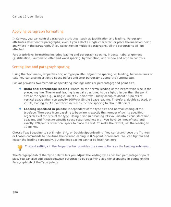
Canvas 12 User Guide
Applying paragraph formatting
In Canvas, you can control paragraph attributes, such as justification and leading. Paragraphattributes affect entire paragraphs, even if you select a single character, or place the insertion pointanywhere in the paragraph. If you select text in multiple paragraphs, all the paragraphs will beaffected.
Paragraph-level formatting includes leading and paragraph spacing, indents, tabs, alignment(justification), automatic letter and word spacing, hyphenation, and widow and orphan controls.
Setting line and paragraph spacing
Using the Text menu, Properties bar, or Type palette, adjust the spacing, or leading, between lines oftext. You can also insert extra space before and after paragraphs using the Type palette.
Canvas provides twomethods of specifying leading: ratio (or percentage) and point size.
Ratio and percentage leading: Based on the normal leading of the largest type size in thepreceding line. The normal leading is usually designed to be slightly larger than the pointsize of the type; e.g., a single line of 12-point text usually occupies about 15 points ofvertical space when you specify 100%or Single Space leading. Therefore, double spaced, or200%, leading for 12-point text increases the line spacing to about 30 points.
Leading specified in points: Independent of the type size and normal leading of thetypeface. The space from baseline to baseline is exactly the number of points specified,regardless of the size of the type. Using point size leading lets you maintain consistent linespacing, and fit text to specific space requirements; e.g., you have 10 lines of text, andexactly 120 points of vertical space to place the text. Tomake the text fit, set the leading to12 points.
Choose Text | Leading to set Single, 11/2, or Double Space leading. You can also choose the Tightenor Loosen commands to fine-tune the current leading in 0.5-point increments. You can tighten andloosen the leading repeatedly, but the line spacing cannot be less than zero.
The text settings in the Properties bar provides the same options as the Leading submenu.
The Paragraph tab of the Type palette lets you adjust the leading by a specified percentage or pointsize. You can also add space between paragraphs by specifying additional spacing in points on theParagraph tab of the Type palette.
590
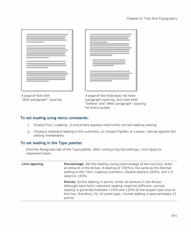
Chapter 6: Text And Typography
A page of text with“after paragraph” spacing
A page of text that does not haveparagraph spacing, but uses both“before” and “after paragraph” spacingfor block quotes
To set leading using menu commands:
1. Choose Text | Leading. A checkmark appears next to the current leading setting.
2. Choose a standard leading in the submenu, or choose Tighten or Loosen. Canvas applies thesetting immediately.
To set leading in the Type palette:
Click the Paragraph tab of the Type palette. After configuring the settings, click Apply toimplement them.
Line spacing Percentage: Set the leading using a percentage of the line size. enteran amount in the At box. A leading of 100% is the same as the Normalsetting in the Text | Leading submenu. Double space is 200%, and 1.5space is 150%.
Points: Se the leading in points. Enter an amount in the At box.Although each font’s standard leading might be different, normalleading is generally between 110% and 125%of the largest type size onthe line; therefore, for 10-point type, normal leading is approximately 12points.
591

Canvas 12 User Guide
Before paragraph To insert space before the first line of a paragraph, specify the numberof points in the Before paragraph box. This option does not apply to thefirst paragraph in a column.
After paragraph To insert space after the last line of a paragraph, specify the number ofpoints in the After paragraph box. Canvas inserts space after everyparagraph, including the last paragraph in a column.
Force a line break without creating a new paragraph by pressing Shift-Return. See "Tocontrol line breaks:" on page 592.
To control line breaks:
“Soft” returns are forced line breaks which do not create new paragraphs.
1. Place the insertion point where you want the soft return.
2. Press Shift+Enter. Text to the right of the soft return moves to the next line.
To view soft return symbols: Choose Layout | Display | Show Text Invisibles.
To hide soft return symbols: Choose Layout | Display | Hide Text Invisibles.
Setting indents
You can set the amount of space between the left and right borders of a text object and the edges ofeach paragraph using the Indents tab of the Type palette or the Properties bar. For text wrappedaround an object, you can also use the Indents tab to set the distance between the edge of the objectand the text.
592

Chapter 6: Text And Typography
Left 1 in. Left 1 in., Right 1 in.
First line 1.5 in.,Left 1 in.
First line 1 in.,Left 1.5 in
The Properties bar shows indent positions for one selected object at a time; therefore, youcannot use it to set indents for the preset format or for multiple selected objects.
To set indents on the Type palette:
1. Click the Indent tab of the Type palette.
2. Enter the indent settings.
3. Click Apply to implement the indent settings.
593
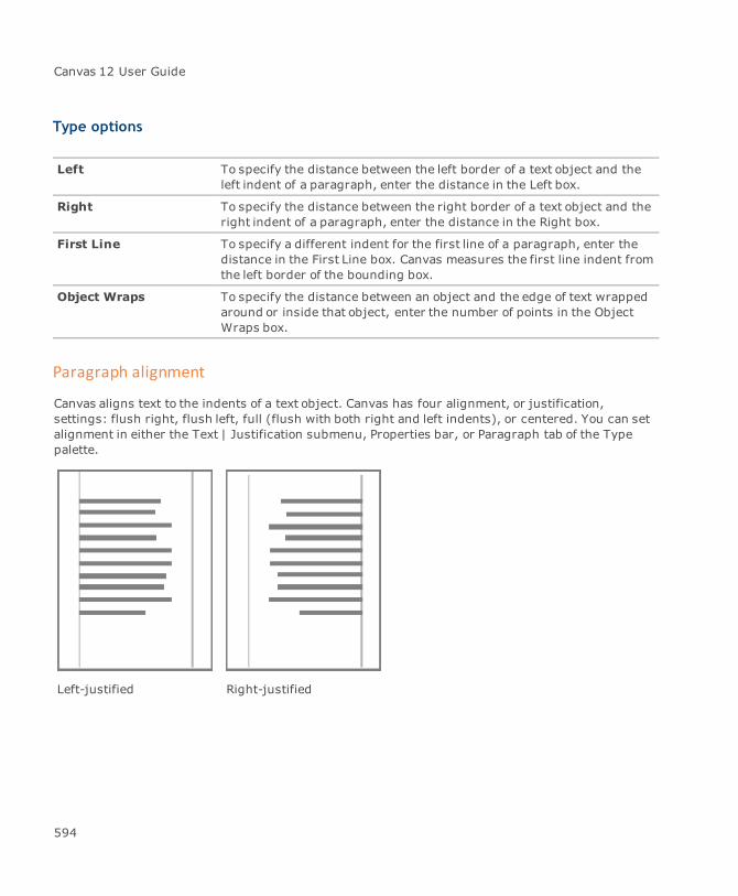
Canvas 12 User Guide
Type options
Left To specify the distance between the left border of a text object and theleft indent of a paragraph, enter the distance in the Left box.
Right To specify the distance between the right border of a text object and theright indent of a paragraph, enter the distance in the Right box.
First Line To specify a different indent for the first line of a paragraph, enter thedistance in the First Line box. Canvas measures the first line indent fromthe left border of the bounding box.
Object Wraps To specify the distance between an object and the edge of text wrappedaround or inside that object, enter the number of points in the ObjectWraps box.
Paragraph alignment
Canvas aligns text to the indents of a text object. Canvas has four alignment, or justification,settings: flush right, flush left, full (flush with both right and left indents), or centered. You can setalignment in either the Text | Justification submenu, Properties bar, or Paragraph tab of the Typepalette.
Left-justified Right-justified
594
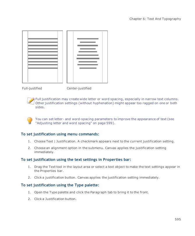
Chapter 6: Text And Typography
Full-justified Center-justified
Full justification may createwide letter or word spacing, especially in narrow text columns.Other justification settings (without hyphenation) might appear too ragged on one or bothsides.
You can set letter- and word-spacing parameters to improve the appearance of text (see"Adjusting letter and word spacing" on page 599).
To set justification using menu commands:
1. Choose Text | Justification. A checkmark appears next to the current justification setting.
2. Choose an alignment option in the submenu. Canvas applies the justification settingimmediately.
To set justification using the text settings in Properties bar:
1. Drag the Text tool in the layout area or select a text object to make the text settings appear inthe Properties bar.
2. Click a justification button. Canvas applies the justification setting immediately.
To set justification using the Type palette:
1. Open the Type palette and click the Paragraph tab to bring it to the front.
2. Click a Justification button.
595
Canvas 12 User Guide
3. Click Apply to implement the justification setting.
Using vertical justification
Canvas can align text relative to the top and bottom borders of text objects. Canvas has four verticaljustification, or alignment, settings: Top, Bottom, Vertical Full, and Vertical Center. Verticaljustification applies to an entire text object. Top vertical justification is the default setting for newtext objects. Copying or duplicating text objects preserves their vertical justification settings;however, if you copy a text selection and paste it into another object, the text follows the verticaljustification of the text object in which you paste it.
To change the vertical justification:
1. Select one or more text objects.
2. Choose Text | Justification.
3. Choose a vertical justification setting. A checkmark appears next to the selected setting.
Theremust be space in the text object to use vertical justification, not including spacecreated by empty paragraphs. The text objects must be created with the Text Object tool,not the Text tool.
Vertical justification settings
Top: Sets all lines of type starting from the top of a text object. This is the traditional verticalalignment for text objects; e.g., if a text object contains three lines of type, they appear atthe top of the text object. Spacing between lines is controlled by the Line Spacing, BeforeParagraph, and After Paragraph settings of the text.
Vertical Center: Sets all lines of type so they are spaced evenly above and below thevertical center of a text object. If a text object contains three lines of type, for example, thelines appear at the center of the text object. Spacing between lines is controlled by the LineSpacing, Before Paragraph, and After Paragraph settings of the text.
Bottom: Sets all lines of type at the bottom of the text object. If a text object contains threelines of type, for example, the lines appear at the bottom of the text object. Spacing betweenlines is controlled by the Line Spacing, Before Paragraph, and After Paragraph settings of thetext.
Vertical Full: Sets all lines of type so they are evenly spaced between the top and bottomborders of the text object. If a text object contains three lines of type, for example, one lineappears at the top, one appears at the center, and one appears at the bottom of the text
596
Chapter 6: Text And Typography
object. Because it distributes type from the top to the bottom of a text object, Vertical Fulljustification can cause very wide spacing between lines if a large text object contains a littletext. You can drag a handle at the top or bottom of a text object to adjust its height and alterthe spacing between lines of text.
Top Vertical Center
Bottom Vertical Full
Paragraph rules
Paragraph rules are horizontal lines that Canvas draws above a paragraph, below a paragraph, orboth. You can select pen type, dash, color, length, and offset for paragraph rules.
597

Canvas 12 User Guide
To apply paragraph rules:
1. Place the insertion point or make a selection in the paragraph. You can highlight multipleparagraphs to select them.
2. Choose Text | Rules.
3. In the Paragraph Rules dialog box, select Rule Above or Rule Below. You can select either orboth options. The options for Rule Above and Rule Below can be set independently.
4. Select rule options, then click Apply to preview the rules.
5. Click OK to apply the rules and close the dialog box.
The Paragraph Rules command is not available unless a text object is in edit mode.
Paragraph Rules options
Rule Above and RuleBelow
Draws rules above or below selected paragraphs. Both can be selected.The size, placement, and attributes of rules are based on the settings inthe dialog box. If a paragraph has rules and you clear the check boxes,Canvas removes the rules.
Length Use the menu to choose an option for the length of paragraph rules.
Indents Sets the rule length based on the values in the From Left and FromRightboxes. These values set the distances from the ends of the rules to theright and left borders of the text object (independent of paragraphindents).
Text Makes the rule length equal to the first line (for rules above) or last line(for rules below) of a paragraph. The From Left and From Right optionsare not available when the Text option is selected.
Offset Enter a value in points to space the rule away from the adjacent line oftext. The position for rules above is measured from the descenders ofthe last line of the previous paragraph. For rules below, the position ismeasured from the descenders of the last line of the current paragraph.You can enter a minimum value of -10 points to move the rule closer tothe text. You can enter a maximum value of 72 points to move the ruleaway from the text.
598
Chapter 6: Text And Typography
Pen Select a stroke for the rule from the Pen pop-up palette. You can select asolid pen, neon, or parallel stroke.
Dash To apply a dash to the rule, select a dash style from the Dash pop-uppalette.
Color Select a color for the rule from the Color pop-up palette.
Adjusting letter and word spacing
Depending on the type of justification you choose, you might want to adjust letter and word spacingto reduce raggedness or eliminate unusual spacing; e.g., left-justified paragraphs might appear tooragged on the right edge, and full-justified paragraphs might have large spaces between charactersand words.
You can specify a minimum line width for a paragraph to reduce raggedness. In addition, Canvas hasletter- and word-spacing parameters to let you specify minimum, maximum, and desired spacingguidelines.
To adjust letter and word spacing:
1. Depending on how you want the letter and word spacing settings to apply, do one of thefollowing:
To change existing text: Select the paragraphs or text objects. To set spacing for onlyone paragraph, place the insertion point anywhere in the paragraph.
To set the spacing before typing a new paragraph: Place the insertion point at thebeginning of the paragraph.
To apply the spacing settings to the preset format: Deselect all objects.
2. Open the Type palette by choosing Text | Type.
3. Click the Paragraph tab to bring it to the front, if necessary.
4. Depending on the type of justification applied to the text, use the following options on theParagraph tab:
For right-, left-, and center-justified text: To set the “Minimum line widths,” enter apercentage in the text box. The percentage tells Canvas to adjust letter and word spacingso that each line is at least as wide as specified; e.g., if you create a two-inch wide, left-justified paragraph and set the minimum line width to 75%, Canvas adjusts the spacing
599
Canvas 12 User Guide
so that each line is at least 1.5 inches wide. Only the last line in a paragraph is unaffectedby the “Minimum line widths” setting.
For full-justified text: To tell Canvas when the last line of a paragraph is wide enoughto be justified (flush with both right and left margins), enter a percentage in the “JustifyLast Line Within” box; e.g., you create a two-inch wide, full-justified paragraph and tellCanvas to justify the last line within 75%. If the last line is less than 1.5 inches wide,Canvas does not justify the line. However, if the last line is wider than 1.5 inches, Canvasjustifies the line.
5. To set letter and word spacing parameters, click the Spacing tab to bring it to the front, ifnecessary. Set theminimum, desired, and maximum spacing in the Letter and Word areas.Specify each setting as a percentage of the current spacing. The desired spacing must begreater than the minimum and less than themaximum. The maximum spacing cannot be lessthan the minimum.
Canvas will try to adjust spacing to the desired percentage, but might not be able todepending on minimum line width and justification settings. In these cases, Canvas will thentry to adjust the spacing within theminimum and maximum percentages you specify.However, if the minimum and maximum spacing parameters are still in conflict withminimum line width or full justification settings, Canvas will ignore the spacing parameters.
If you applied kerning to characters within the selection, Canvas adjusts thespacing as a percentage of the kerning.
To change the spacing of a paragraph by a set amount, you can set the minimum, desired,and maximum percentages to the same value. This has a similar effect to kerning the entireparagraph.
6. Click Apply to implement the settings.
Automatic hyphenation
Canvas can insert a hyphen in the last word of a line to give text objects a more balanced, evenappearance. You can also control the hyphenation properties so that Canvas only hyphenates underspecific circumstances. Hyphenation settings apply to entire paragraphs. To hyphenate a specificword, you can manually insert a hyphen.
To use automatic hyphenation:
1. Click the Hyphen tab to bring it to the front. Turn hyphenation on and configure the followingsettings.
2. Click Apply to implement the hyphenation settings.
600
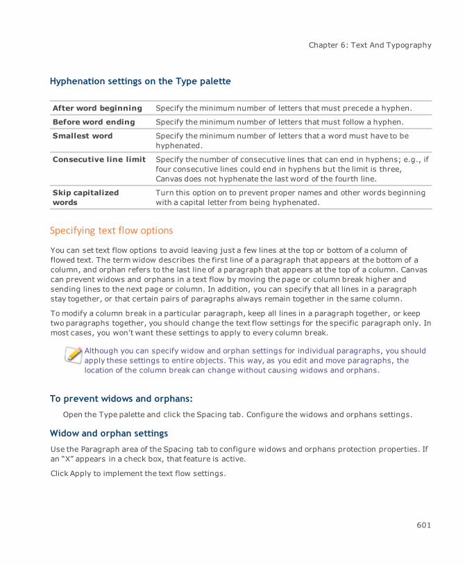
Chapter 6: Text And Typography
Hyphenation settings on the Type palette
After word beginning Specify theminimum number of letters that must precede a hyphen.
Before word ending Specify theminimum number of letters that must follow a hyphen.
Smallest word Specify theminimum number of letters that a word must have to behyphenated.
Consecutive line limit Specify the number of consecutive lines that can end in hyphens; e.g., iffour consecutive lines could end in hyphens but the limit is three,Canvas does not hyphenate the last word of the fourth line.
Skip capitalizedwords
Turn this option on to prevent proper names and other words beginningwith a capital letter from being hyphenated.
Specifying text flow options
You can set text flow options to avoid leaving just a few lines at the top or bottom of a column offlowed text. The termwidow describes the first line of a paragraph that appears at the bottom of acolumn, and orphan refers to the last line of a paragraph that appears at the top of a column. Canvascan prevent widows and orphans in a text flow by moving the page or column break higher andsending lines to the next page or column. In addition, you can specify that all lines in a paragraphstay together, or that certain pairs of paragraphs always remain together in the same column.
Tomodify a column break in a particular paragraph, keep all lines in a paragraph together, or keeptwo paragraphs together, you should change the text flow settings for the specific paragraph only. Inmost cases, you won’t want these settings to apply to every column break.
Although you can specify widow and orphan settings for individual paragraphs, you shouldapply these settings to entire objects. This way, as you edit and move paragraphs, thelocation of the column break can change without causing widows and orphans.
To prevent widows and orphans:
Open the Type palette and click the Spacing tab. Configure the widows and orphans settings.
Widow and orphan settings
Use the Paragraph area of the Spacing tab to configure widows and orphans protection properties. Ifan “X” appears in a check box, that feature is active.
Click Apply to implement the text flow settings.
601
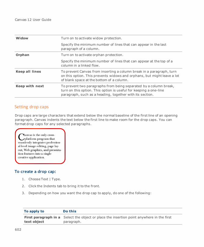
Canvas 12 User Guide
Widow Turn on to activate widow protection.
Specify theminimum number of lines that can appear in the lastparagraph of a column.
Orphan Turn on to activate orphan protection.
Specify theminimum number of lines that can appear at the top of acolumn in a linked flow.
Keep all lines To prevent Canvas from inserting a column break in a paragraph, turnon this option. This prevents widows and orphans, but might leave a lotof blank space at the bottom of a column.
Keep with next To prevent two paragraphs from being separated by a column break,turn on this option. This option is useful for keeping a one-lineparagraph, such as a heading, together with its section.
Setting drop caps
Drop caps are large characters that extend below the normal baseline of the first line of an openingparagraph. Canvas indents the text below the first line tomake room for the drop caps. You canformat drop caps for any selected paragraphs.
To create a drop cap:
1. Choose Text | Type.
2. Click the Indents tab to bring it to the front.
3. Depending on how you want the drop cap to apply, do one of the following:
To apply to Do this
First paragraph in a Select the object or place the insertion point anywhere in the firsttext object paragraph.
602

Chapter 6: Text And Typography
To apply to Do this
All other paragraphs Place the insertion point in a paragraph, or select a paragraph. Youcan also select multiple consecutive paragraphs.
A new paragraph youare about to type
Place the insertion point at the beginning of the paragraph.
The preset format Deselect all objects. Canvas will apply drop caps to the firstparagraph of all new text objects you create with the Text tool.
4. Configure the drop cap options described below.
5. Click Apply.
Drop cap settings
Lines Specify the number of lines you want the drop caps to occupy. Thisdetermines the vertical height of the drop cap.
Characters Specify the number of characters to enlarge for drop caps. Canvasalways applies this setting beginning with the first character in aparagraph.
Inserting headers and footers
You can add header and footer text objects using commands in the Text | Insert menu. Headers andfooters are special text objects that can contain codes for the current date, current time, and pagenumber, in addition to text you type. Canvas updates the date, time, and page number codes eachtime it redraws the screen.
In Publication documents, Canvas inserts headers at the top of the publication layout area (above thepagemargins) and footers at the bottom of the publication layout area (below the page margins). Inother documents, Canvas places the header in the upper left corner of the page and the footer in thelower left corner.
Both types of objects initially span the width of the page, but you can resize and move them just likeother text objects.
You can’t add headers and footers in edit mode, press Esc to end text editing.
603
Canvas 12 User Guide
To insert header and footer text objects:
Choose Text | Insert | Header or Text | Insert | Footer. Canvas creates the text object, and places it inedit mode.
Inserting dates, times, and page numbers
Insert date, time, and page number codes in header and footer text objects. Canvas will update thevalues for these codes each time it redraws the screen, unless the Date Stamp and Time Stampcommands are used. Canvas uses the date and time as set in the operating system.
Refer to your system documentation for information on setting the current date and time.
You can insert the current date and time in text objects (see "Text objects" on page 560); however,Canvas does not update this text since it is “stamped” into the document as regular text. You canchange page number (symbol $P) and total page count (symbol $T) displayed by adding a simpleformula to them.
You can apply text formatting or Type Styles (see "Working with type styles" on page 605) to thedate, time, and page codes; e.g., change fonts, type sizes, and justification, as you would applyformatting to normal text with the Text menu, Properties bar, or Type palette.
When entering the formula, remember the following:
The formula can contain only “+” and “-” as operators or numbers. Do not use spacesbetween the characters.
The formula may be of any length, but it must be in a formula format.
To insert the date, time, or page number:
With a header or footer object in edit mode, choose Text | Insert (see "Date and time commands"on page 604 and "Page numbering commands" on page 605).
Date and time commands
To insert In this type of object Do this
Updating date code Header or footer Choose Insert | Date, or type $d
Date stamp Any text object Choose Insert | Date Stamp
Updating time code Header or footer Choose Insert | Time, or type $e
Time stamp Any text object Choose Insert | Time Stamp
604
Chapter 6: Text And Typography
Page numbering commands
To insert In this type of object Do this
Current pagenumber
Header or footer (pagecount is static in normaltext objects)
Choose Text | Insert | Page#, or type $p
Total pagecount
Header or footer (pagecount is static in normaltext objects)
Choose Text | Insert | Total Page #, or type $t
Page # of totalpagese.g., Page 2 of8
Header or footer (pagecount is static in normaltext objects)
Choose Text | Insert | Page# of Total Page#, or typePage $P of $T
Page -# of totalpagese.g., Page -2 of4
Header or footer (pagecount is static in normaltext objects)
Choose Text | Insert | Page#+4-8 of Total Page#+4-8, or type Page $P+4-8 of $T+4-8
If you unintentionally place spaces between the page numbers and operators, the pagenumbering will create errors; e.g., the formula Page $P+4 -8 of $T+4 -8 would appear asPage 6 -8 of 12 -8.
Working with type styles
Define text formatting settings and save them as character and paragraph type styles using theStyles tab in the Type palette. Canvas stores type styles with documents. When you open adocument, Canvas loads the associated styles so you can apply them; however, Canvas also gives youthe option of saving defined styles in a file which can be shared with others (see "Saving and loadingtype styles" on page 609).
Before you start defining type styles, see "Formatting text" on page 577 to learn aboutfonts, font styles, etc.
Type styles make it easy to apply formats and maintain consistency throughout a document. Basestyles on each other to form a “family” of styles, so that styles inherit the character and paragraphattributes of a parent style. Organizing styles in this manner makes global style changes a simplematter of changing the parent style.
605
Canvas 12 User Guide
To open the Type palette:
Choose Text | Type or double-click the Text tool.
Creating new type styles
You can create two kinds of styles, character and paragraph. Use a paragraph style for an entireparagraph of text. Use a character style for a character, word, phrase, or part of a paragraph. Afterestablishing character and paragraph styles, apply them to your text.
Paragraph style attributes:
Leading
Indents
Justification
Drop caps
Hyphens
Letter and word spacing
Text flow settings
Character attributes and colors
Character style attributes:
Font
Type size
Font style
Capitalization style
Baseline position
Kerning
Colors
606
Chapter 6: Text And Typography
To create a new style:
1. Choose Text | Type.
2. In the Type palette, choose the paragraph and character formatting you want to use for thenew style.
3. Click the Styles tab to bring it to the front.
Example: Displays a sample of text with the current formatting settings applied.
Description: Lists the current character or paragraph attributes. The C and ¶ iconstoggle between descriptions of character and paragraph attributes.
4. Click Create.
5. In the Create Type Style dialog box, enter a name for the new style.
6. Click the Character or Paragraph icon.
7. Select any additional settings.
8. Click Save.
To create a style based on already formatted text:
1. Place the insertion point in the text that contains the formatting you want to use to create thestyle.
2. Choose Text | Type.
3. Click the Styles tab.
4. Click Create.
5. In the Create Type Style dialog box, enter a name for the new style.
6. Click the Character or Paragraph icon.
7. Select any additional settings.
8. Click Save.
607

Canvas 12 User Guide
Create Type Style dialog box
Character orParagraph
Click a button to specify what kind of style you want to create.
Based on If there are existing styles, choose a style name on which to base thenew style. To disable this feature, choose None (see "Using stylefamilies" on page 608).
Include Select the attributes to save as part of the style. You can include inksettings (fill and stroke attributes that have been applied to existingtext) in character and paragraph styles. These inks don’t affect thecurrent inks for vector objects.
For paragraph styles, you can also include font attributes and tabsettings.
If a text selection has a frame or background ink, you can’t include theseattributes in a style. In addition, when text doesn’t have a stroke, youcan’t include strokes in a style.
Style name Type a name for the style.
Using style families
When you base a style on an existing style, the new style “inherits” the attributes of the parent style.When the parent style changes, Canvas also updates all related styles. In addition to inheritedattributes, the style possesses its own attributes, which you specify.
A style’s own attributes always take precedence over attributes inherited from the parentstyle.
You create a style, Body2, based on a parent style, Body1. The fonts are the same, but the type sizesare different. Body2 uses 10 point type, while Body1 uses 12 point. If you change the font for theparent style, the font also changes for Body2. However, if the point size changes for the parent style,Body2 does not change, because Body2’s own attributes take precedence. Tomake Body2 always usethe same point size as Body1, you must set the point sizes equal, base Body2 on Body1, and save thestyle again.
In addition, if you later change Body2’s font, this style will no longer inherit fonts from the parentstyle. Body2’s font will override Body1’s font setting.
Careful planning will save you from time-consuming corrections when basing styles on each other. Insome cases, changing a parent style’s attributes may cause unwanted changes throughout the style
608

Chapter 6: Text And Typography
family; e.g., if you base ten styles on Body1, and later decide that you want Body1 (but not the wholefamily of styles) to be double spaced, you must first change the leading for Body1, then remove theleading setting from each of the other ten styles.
Saving and loading type styles
You can save type styles to files and then load them into other documents. This feature helpsmaintain consistency between documents, and lets you share type styles with other Canvas users.
To save a type style to disk:
1. Click the Type palette menu button on the Styles tab.
2. ChooseSave style.
3. In the Save As dialog box, type a file name and specify a location to save the file.
4. Click Save.
To load a type style:
1. Click the Type palette menu button on the Styles tab.
2. Choose Load style.
3. In the Open dialog box, locate and select the styles file.
4. Click Open.
Copying type styles between documents
Another way to transfer type styles from one document to another is to copy text that uses the styleand paste the text into a different document. Canvas transfers the style with the text. When you savethe document, Canvas also stores the transferred style.
A type style based on another style cannot inherit attributes across documents; e.g., Body2 is basedon a parent style, Body1, and you copy only Body2 to a new document. Body2 in the new documentno longer inherits attributes from Body1, which is still in the original document.
However, if you copy both Body1 and Body2 to a new document, the relationship is preserved, andBody2 will inherit attributes from its parent style.
If you happen to paste a style that already exists in the other document, Canvas modifies the name ofthe pasted style to avoid overriding type styles; e.g., a style named “Body 2” could become “Body 2 -2” when pasted in the new document.
609
Canvas 12 User Guide
Using type styles
Once you’ve created your document’s type styles, you can start applying them, modifying theirattributes, and deleting them from the document. All these processes are done with the Type palette.
Applying type styles
You can apply type styles with the Type palette. Applying type styles with the Type palette is similarto applying individual character or paragraph formats; however, instead of configuring settings oneach of the tabs in the palette, simply choose style names from the menu on the Type palette.
Themenu displays the current type style name. The C and ¶ icons indicate if the style is a characteror paragraph style, or both. If “+++” appears to the right of a style name, the style has beenmodified but not saved. If you choose a style in the menu when “+++” appears next to the currentstyle, you will lose the modifications to the style. Therefore, if you want to use the settings again, youmust save themodified style with a new name before applying other styles.
To apply a style to selected text or text objects with Type palette:
1. Select the text or text objects to which you want to apply a style.
2. Choose a style in themenu on the Type palette.
3. Click Apply.
If the text you selected already had a style applied, Canvas replaces the style with the style youchoose. In addition, if you apply a paragraph style with font attributes to highlighted text, the fontattributes affect the selection only, and the paragraph attributes affect the entire paragraph.
To use a type style as the current format setting:
1. Deselect all text objects by pressing Esc, if necessary.
2. Choose a style in themenu on the Type palette.
3. Click Apply. Canvas formats new text objects with the specified style.
Tips on using type styles
By putting some forethought into the purpose and design of type styles, you ensure that you areusing this feature effectively. This planning will be especially useful when editing styles anddocuments, allowing you tomake a few modifications that update entire documents.
Design a template. If several people need to use the styles, save the styles in a template document.This way, everyone uses a common source for the styles.
610
Chapter 6: Text And Typography
Create a “normal” type style. This will make it easy to revert formatted text to a basic style. When youapply the normal style, it will have the effect of removing or overriding other styles.
Name styles by their function; e.g., a heading style might consist of boldface type. Rather than namethis style “Bold,” name it “Heading,” or something that similarly describes its usage. This will make iteasier to remember when to use which style.
Always apply a style. If you use styles in documents, use them throughout. If you apply styles onlysometimes, you will encounter difficulties maintaining consistency and performing global stylechanges.
Create style families when possible. You might want to use the Based On feature (see "Creating newtype styles" on page 606) to create style families for styles that share some attributes. This will makeglobal changes easier. See "Using style families" on page 608, for more information.
Modifying type styles
You can change the attributes of a type style and save the style with the same name. When youchange a style’s attributes, all styles in the family automatically inherit the new shared attributes.
To modify a type style:
1. Choose the style you want to edit from themenu.
2. Change the style’s attributes. Canvas displays “+++” after the style name to indicate thatchanges weremade to the style.
3. Click the Styles tab and click Create.The current style name is in the Based On menu and Style Name box. To replace the style, donot change these settings.
The options in the Include area change for Character and Paragraph styles.
4. In the Create Type Style dialog box, select the check boxes of the attributes that you want toinclude.
5. Click Save. Confirm that you want to replace the existing style with the new style. Click OK.
Deleting type styles
Tominimize confusion when choosing styles to apply, delete type styles you no longer use. Textusing a deleted type style retains its formatting, but no longer has a named style.
611

Canvas 12 User Guide
To delete a style:
1. Click Delete on the Styles tab of the Type palette.
2. In the Delete Type Style dialog box, choose the style to delete from the Name menu.
3. Click OK.
Applying character formatting
Canvas gives you precise control over the appearance of each character. Set the font, type size, fontstyle, kerning, capitalization style, scale, and baseline position using menu commands, Propertiesbar, or the Character tab of the Type palette.
Character attributes are applied by selecting the specific characters that you want tomodify. Selectany portion of text—from one character to entire text objects (see "Selecting text and objects" onpage 577).
To set character attributes:
1. Choose Text | Type.
2. Click the Character tab.
The Character tab lets you control all character attributes. Some attributes, such as typeface, type size, font style, baseline, and kerning, are also available in the Text menu orProperties bar.
Type Palette Character Tab
Font Choose a typeface in the menu.
Size Choose a type size in the menu or type a number in the text box.
Style Click a button to select a font style.
Case Choose a capitalization style in themenu.
Baseline Specify subscript or superscript settings to one hundredth of a pointprecision.
Kerning Tighten and loosen kerning by hundredths of a point.
Scaling Specify percentages by which you want to scale the current type size.Set individual horizontal and vertical scaling percentages.
Locks To prevent accidental or unwanted changes to the type face, type size,or font style of specific text, you can set these locks. If you want tochange locked text, you must first unlock the text.
612
Chapter 6: Text And Typography
Preventing changes to character attributes
On the Character tab in the Type palette, you can lock the current font, type size, and font style toprevent accidental changes. This feature is especially useful when several people are using the sameCanvas document. In addition, you can also use this feature to selectively exempt sections of textfrom global formatting changes. Once you lock a setting, no one can change it without first unlockingit.
To lock character attributes:
1. Click the Character tab on the Type palette.
2. Change any font, size, or style attributes at this time.
3. Click the Lock button to the right of the attribute.
4. Click Apply. Canvas first applies the new font attributes, then locks the new attributes.
Text editing & proofing
You can insert, search, replace, move, delete, copy, and spell check text in Canvas documents. Thissection describes how to navigate through text for editing, make text selections, and use spellingtools and the Find feature for text search-and-replace.
Text edit mode
To edit text, you must put a text object in edit mode. In edit mode, you can revise, delete, insert, andselect specific text. Only one object is in text edit mode at a time.
Entering text edit mode
Put a text object in edit mode with the Text tool or Selection tool. When a text object is in edit mode,the text object becomes opaque, the selection handles disappear, and a flashing insertion pointappears. Also, the Text tool becomes the active tool.
To enter edit mode using the Text tool:
Select the Text tool and click in a text object. An insertion point appears where you click, and youcan begin typing or editing.
613
Canvas 12 User Guide
To enter edit mode using the Selection tool:
With the Selection tool, double-click a text object. If you double-click on a word, the wordbecomes selected and is highlighted. The Text tool is selected, and you can begin typing orediting.
To edit text bound to a path:
With the Path Text tool or the Text tool, click the text. An insertion point appears in the bound text,and you can begin typing or editing.
To leave text edit mode:
Press Esc when you finish text editing. Canvas switches to the Selection tool from the Text tool.The text object you were editing is selected.
Text selection and navigation
Move the insertion point and select characters, words, lines, and paragraphs using themouse orkeyboard.
Themouse lets you quickly select text or text objects and move the insertion point. However, if youwork with a lot of text, you might find that the keyboard techniques let you move the insertion pointmore precisely to edit more quickly.
Making text selections
Before you can cut, copy, move, delete, type over, or perform other operations on text characters,you need to select the text within a text object. You can select text when a text object is in edit mode.
The phrases “selected text,” “text selection,” and “highlighted text” all refer to an active selection ofcharacters within a text object. Selected text appears highlighted; the highlight color depends onyour system’s color settings.
Keep in mind that a text selection is not the same as a selected text object. When you select a textobject, you can move, copy, delete, and perform other operations on the entire object. When youmake a text selection, the editing actions will affect only the highlighted characters within the object.
To deselect all highlighted text:
Click anywhere in the text object or layout. Clicking outside the selected text object createsanother text object at that location.
614

Chapter 6: Text And Typography
Using the keyboard for text editing
While editing text, use the key combinations listed in the following table to move the insertion pointand select text.
Key combinations for text editing
Press this key and these keys to do this in edit mode
None Up arrow, Down arrow,Right arrow, Left arrow
Move insertion point 1 space right or left
Page Up, Page Down Move insertion point 3 lines up at the left margin(PageUp) or down at the right margin (PageDown)
Home, End Move insertion point to the beginning (Home) or end(End) of the text object
Ctrl Right arrow, Left arrow Move insertion point to the next word end (Rightarrow) or beginning (Left arrow)
Up arrow, Down arrow Move insertion point to the left margin of the line, orup 1 line at the left margin (Up arrow), or down 1 lineto the left margin (Down arrow)
Home, End Move insertion point to beginning (Home) or end(End) of line
Shift Right arrow, Left arrow Extend selection 1 space right or left
Up arrow, Down arrow Extend selection 1 line up or down
Page Up, Page Down Extend selection 3 lines up or down
Home, End Extend selection to the beginning (Home) or end(End) of the text object
Shift + Ctrl Right arrow, Left arrow Extend the selection 1 word right or left
Up arrow, Down arrow Extend the selection to left margin (Up arrow) or rightmargin (Down arrow). From the margin, extend theselection to the other margin, or up or down 1 line
Page Up, Page Down Extend selection 3 lines up or down
Using the mouse for text editing
Using the mouse and modifier keys, you can quickly place the insertion point, select specific words,and select sections of text in edit mode. For information on putting a text object in edit mode, see
615
Canvas 12 User Guide
"Text edit mode" on page 613.
Mouse actions for text editing
To do this in text Do this with the pointer
Select a continuous block of text Drag over the text you want to select
Select all text between the insertionpoint and another location
Press the Shift key and click where you want theselection to end. Windows users can use the rightmouse button like the Shift key (hold down the rightbutton and click with the left).
To deselect all highlighted text Click anywhere in the text object. (Clicking outside thetext object creates a new text object at that location orputs another text object into edit mode.)
Deselect text between the insertionpoint and another location in theselection
Press Shift and click in the highlighted text
Select a word Double-click the word
Select a line of text Triple-click the line
Copying, pasting, deleting, and moving text selections
You can cut and copy a text selection, and then paste the selected text in the same document, inanother Canvas document, or to and from a non-Canvas document using the Clipboard. Whetherpasted text retains its formatting depends on the operating systemand the source of the text.
To help you in editing text, display symbols for spaces, paragraph breaks, and tabs. ChooseLayout | Display | Show Text Invisibles. To hide these symbols, choose Layout | Display |Hide Text Invisibles.
Text pasted from another application can be embedded into a Canvas document, using Object Linkingand Embedding (OLE) to preserve its formatting. See "Embedded text objects and editionscontaining text" on page 629.
If you copy and paste selected text (and not an entire text object) within Canvas, the text retains itscharacter attributes, but it adopts the paragraph formatting of the surrounding text.
616

Chapter 6: Text And Typography
To copy and paste selected text:
When you copy selected text, you can create a new text object or insert the text into an existing textobject.
1. Select the text you want to copy.
2. Choose Edit | Copy to copy the selection to the Clipboard.
3. Depending how you want to paste the selection, do one of the following:
To paste text into an existing text object: Put the insertion point in the text whereyou want to paste the insertion.
To paste text as a new text object: Be sure no objects are in text edit mode bypressing Esc. You can set the width of the new text object by selecting the Text tool anddragging. Otherwise, text will be pasted in one long line that might extend off the screen(see "Creating text layouts" on page 563).
4. Choose Edit | Paste to insert the text from the Clipboard.
To cut text:
1. Select the text you want to cut.
2. Choose Edit | Cut. The text is cut to the Clipboard and is ready to be pasted to another area.
To delete text:
1. Select the text you want to delete.
2. Choose Edit | Clear, or press the Delete key.
To replace selected text:
Begin typing, or use the Paste command, to replace a text selection with the text you type or pastefrom the Clipboard. This saves the step of deleting the selected text.
To replace all text in a text object:
Select a text object and begin typing. The text adopts the formatting of the replaced text. Ifmultiple text objects are selected, the text you type replaces the text in the object that wascreated first.
Changing text attributes
While a text object is selected, you can change the formatting of all the text it contains using the Textmenu, Type palette, or Properties bar.
617
Canvas 12 User Guide
Finding and changing text
Use the Text tab in the Find palette to search for specific text or characters in selected text objectsand entire documents. You can replace or delete found text selections one at a time or all at once (see"Text search options" on page 619).
The Text tab also lets you search for text with specific font, size, and style attributes, and change theattributes of found text.
To find and change text:
1. Choose Edit | Find to open the Find palette. Click the Text tab to select it. To search for text,type the text in the Find box or select a special text character. Specify that you want to findonly whole words or text matching the capitalization (case) of the Find text.
2. If you want to replace found text or characters, type the replacement text in the Change Tobox or select a special text character. When the Change To box contains at least onecharacter (including a space), the Change All button is available.
3. Click Find to locate the first occurrence of the specified item. If one or more text objects areselected, Canvas searches the text contained in the first selected object. If no text objectsare selected, Canvas searches the entire document.
4. If Canvas finds the specified item, it highlights the text or character in the document. ClickFind to search for the next occurrence of the specified text. If the Change To box containsreplacement text or a special character, the Change button is available. Click Change toreplace the highlighted itemwith the Change To text or special character.
5. To continue searching, click Find. Repeat the previous step if Canvas finds anotheroccurrence of the search item. When Canvas completes the operation, it displays a message.Click OK in the message box to continue.
You can click Change All to replace all occurrences of the Find text or special character withthe text in the Change To box, without first clicking Find.
Finding and changing text attributes
You can search for and change text attributes (whether or not you also search for specific text). Thetext attributes you can seek and change are font, type size, and text style.
618

Chapter 6: Text And Typography
To search for text attributes:
1. Click the arrow at the bottom-left corner of the Find palette.
2. In the Find Attributes section, select a font name from the font pop-up menu. Type a size (inpoints) or select a size from the size pop-up menu. Click the style buttons to set the stylesyou want.
3. In the Change Attributes To section, specify replacement attributes in the same way that youspecify the Find attributes.
4. Click Change or Change All to replace the attributes specified in the Find Attributes sectionwith the attributes specified in the Change Attributes To section. If you have also typed textin the Find box, the replacement text attributes can be applied only to text that matches theFind text.
Clicking the Clear button removes all settings in the Find Attributes and Change Attributes To areas.
Text search options
The options on the Text tab in the Find palette let you specify criteria for text and character searchingand replacement.
Find Type the text or select the special character that you want to find. Leavethis box blank to search for text attributes only.
Change To If you want to replace found text or characters, enter replacement text orcharacter (1) here. If you want to delete found text or characters, leavethe Change To box empty.
Whole Word SelectWhole Word to specify that the Find text is an entire word; e.g., ifyou type “time” and select Whole Word, Canvas will not find “times,”“untimely,” or “timer.”
Match Case Select Match Case to include the capitalization of the Find text in thesearch criteria; e.g., if you type “Time” and select this option, Canvaswill not find “TIME” or “time.”
Change If Canvas locates the specified text and attributes, it highlights the textin the document. Click Change to replace the highlighted text with theChange To text and to apply the replacement attributes specified in theChangeAttributes To section.
Change All Click to replace all occurrences of the text and attributes you specifiedwith the replacement text and attributes. Canvas makes the changeswithout highlighting found text.
Find button Click to search for the next occurrence of text specified in the Find text
619
Canvas 12 User Guide
box and attributes specified in the Find Attributes area.
Find Attributes The text attributes that you specify here tell Canvas what to search for.
Click to display Attributes options.
To search for a particular font, select the font name from the pop-upmenu.
To search for a type size, enter the size or select the size from the pop-up menu.
To search for a type style, select a style button. You can select bold,italic, underline, outline, strikethrough, and shadow styles.
Change Attributes To The text attributes that you specify here can be applied to text thatmatches the attributes specified in the Find Attributes area.
Select the font from the pop-up menu.
Enter the replacement size (in points) or select the size from the pop-upmenu.
Click style buttons to specify replacement styles. You can choose bold,italic, underline, outline, strikethrough, and shadow.
Clear. Click to delete all the settings from the Find Attributes and ChangeAttributes To areas.
Automatic text correction
Canvas can automatically fix typographical mistakes as you type. The Auto Correct manager lets youselect several automatic correction options. It also lets you specify common misspellings, typingerrors, and abbreviations that you want Canvas to replace as you type.
When any text replacement option is active, Canvas checks each word you type. It corrects orreplaces text as appropriate once you press the Spacebar.
Auto Correct options
Use the options in the Auto Correct manager to specify corrections you want Canvas tomake as youtype (see "Setting preferences" on page 97).
620
Chapter 6: Text And Typography
To set up automatic correction:
1. Choose Text | Spell Checker | Auto Correct.
2. In the Auto Correct manager, select the replacement options to use.
3. Click OK to implement the current settings.
Setting up text replacement
Specify abbreviations, common misspellings, and other text that you want Canvas to replace as youtype.
Use this feature to expand abbreviations for common phrases and long names that you typethroughout a document: e.g., if you often type “Department of Agriculture,” you can specify that theabbreviation “DA” be replaced by the full name.
To set up text replacement:
1. Choose Text | Spell Checker | Auto Correct. In the Auto Correct manager, be sure ReplaceText as You Type is selected.
2. In the Replace box, type text that you want to be replaced. In theWith box, type thereplacement text. Click Add to place the text in the scrolling list.
3. Repeat this procedure to specify more automatic replacements. Add as many items to thescrolling list as you want. When you finish, click OK.
Auto Correct does not remove specified text from a document if you type nothing in theWithbox. Also, Auto Correct won’t replace spaces with more or fewer spaces (such as replacingtwo spaces with one space); however, you can use the Text tab in the Find palette to findand replace spaces.
To remove replacement entries:
Select the entry in the scrolling list and click Delete.
Automatic spelling correction
When you use the Spelling menu ("To use the spelling pop-up menu:" on page 626) to correct amisspelling, Canvas adds the item to the Auto Correction list. Themisspelled word appears underReplace and the correction appears under With. If you make the same spelling mistake again and“Replace Text as You Type” is selected in the Auto Correct manager, Canvas corrects the error. If“Replace Text as You Type” is not selected, Canvas won’t make these automatic corrections.
621
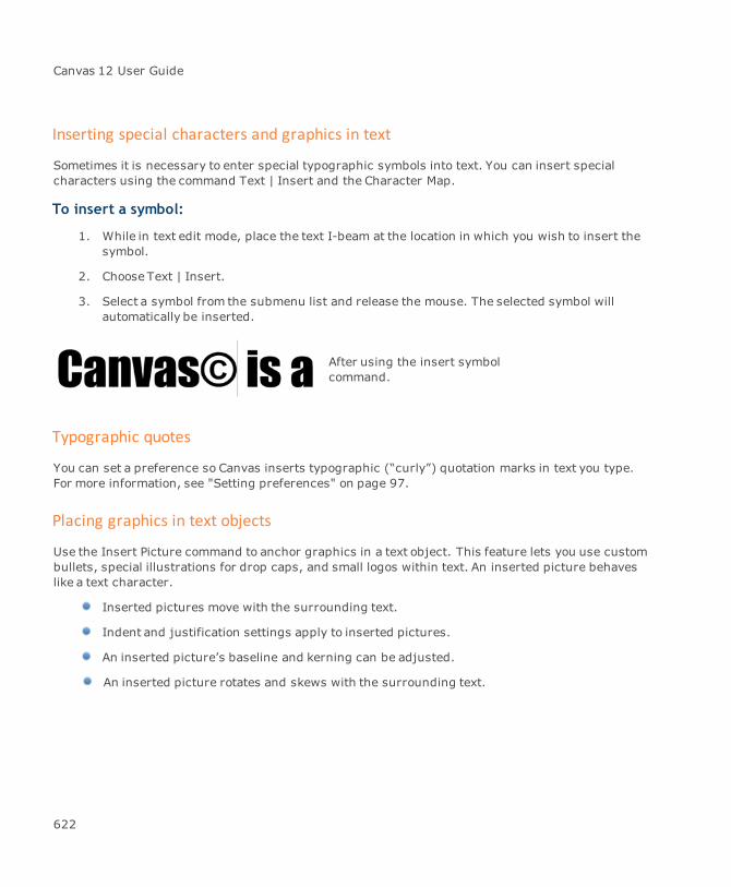
Canvas 12 User Guide
Inserting special characters and graphics in text
Sometimes it is necessary to enter special typographic symbols into text. You can insert specialcharacters using the command Text | Insert and the Character Map.
To insert a symbol:
1. While in text edit mode, place the text I-beam at the location in which you wish to insert thesymbol.
2. Choose Text | Insert.
3. Select a symbol from the submenu list and release the mouse. The selected symbol willautomatically be inserted.
After using the insert symbolcommand.
Typographic quotes
You can set a preference so Canvas inserts typographic (“curly”) quotation marks in text you type.For more information, see "Setting preferences" on page 97.
Placing graphics in text objects
Use the Insert Picture command to anchor graphics in a text object. This feature lets you use custombullets, special illustrations for drop caps, and small logos within text. An inserted picture behaveslike a text character.
Inserted pictures move with the surrounding text.
Indent and justification settings apply to inserted pictures.
An inserted picture’s baseline and kerning can be adjusted.
An inserted picture rotates and skews with the surrounding text.
622
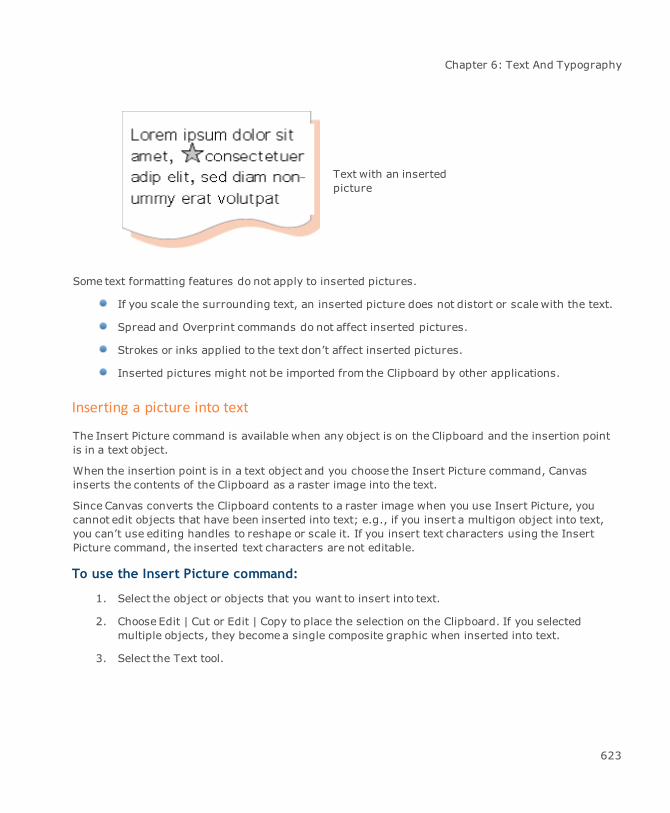
Chapter 6: Text And Typography
Text with an insertedpicture
Some text formatting features do not apply to inserted pictures.
If you scale the surrounding text, an inserted picture does not distort or scalewith the text.
Spread and Overprint commands do not affect inserted pictures.
Strokes or inks applied to the text don’t affect inserted pictures.
Inserted pictures might not be imported from the Clipboard by other applications.
Inserting a picture into text
The Insert Picture command is available when any object is on the Clipboard and the insertion pointis in a text object.
When the insertion point is in a text object and you choose the Insert Picture command, Canvasinserts the contents of the Clipboard as a raster image into the text.
Since Canvas converts the Clipboard contents to a raster image when you use Insert Picture, youcannot edit objects that have been inserted into text; e.g., if you insert a multigon object into text,you can’t use editing handles to reshape or scale it. If you insert text characters using the InsertPicture command, the inserted text characters are not editable.
To use the Insert Picture command:
1. Select the object or objects that you want to insert into text.
2. Choose Edit | Cut or Edit | Copy to place the selection on the Clipboard. If you selectedmultiple objects, they becomea single composite graphic when inserted into text.
3. Select the Text tool.
623

Canvas 12 User Guide
4. Click in the text where you want to insert the graphic. An insertion point appears where youclick.
5. Choose Text | Insert Picture. The Clipboard contents appear at the insertion point.
How inserted pictures affect leading
When you use the Insert Picture command, the leading of the paragraph might change, dependingon the Line spacing method:
If the Line spacing is defined by Percentage, Canvas adjusts the Line spacing to fit thepicture based on the defined percentage, if necessary.
If the Line spacing is defined by Points, the spacing between lines stays the same,regardless of the size of the picture.
Line spacing set to 100%
Line spacing set to 12points
Using dynamic objects for inserted pictures
If you want to be able to edit an inserted picture, you can insert a dynamic object into text. A dynamicobject is an object linked to an editable original in the Symbol Library palette. If you change the
624

Chapter 6: Text And Typography
original in the Symbol Library palette, the inserted picture dynamic object will change to match theoriginal.
For example, you can use the Insert Picture command to place simple placeholder dynamic objects(such as small squares) where you want finished graphics to appear in text. When the final graphicis available, replace the placeholder dynamic object in the Symbol Library palette with the finishedgraphic. With this method, you do not have to change each instance of a graphic individually or alterthe publication’s layout.
Placeholder object
Final graphic
Text with placeholder dynamicobject inserted
Placeholder dynamic objectreplaced by apple graphic
Checking the spelling of text
Canvas can check the spelling of all text in a document, including text bound to a path by the PathText tool or the Bind Text command. Canvas can check the spelling of specific words, selections andentire documents. Canvas can also check the spelling of words as you type.
Canvas checks the spelling of text by looking up words in the Canvas Dictionary and the UserDictionary. The Canvas dictionary contains 100,000 words. You can add words to the User Dictionaryto stop Canvas frommarking unrecognized words that are spelled correctly.
The Canvas dictionary file can’t be modified.
625
Canvas 12 User Guide
Showing and hiding unrecognized words
Canvas marks words that it can’t find in either the Canvas Dictionary or the User Dictionary with a redwavy underline. Canvas can check spelling while you type or after you finish entering text.
When Show Spelling Errors is active, Canvas checks the spelling of a word after you type it and pressthe Spacebar, tab, or deselect the text object. Canvas marks an unrecognized word with a red wavyunderline.
To mark unrecognized words:
Choose Layout | Display | Show Spelling Errors.
To not mark unrecognized words:
Choose Layout | Display | Hide Spelling Errors.
Using the spelling pop-up menu
While using the Text tool to edit text, you can choose suggested replacements for words marked asunrecognized.
The spelling pop-up menu lets you choose replacement words. You can also use themenu to addunrecognized words to the User Dictionary.
To use the spelling pop-up menu:
With a text object in edit mode, point to a word that Canvas has marked as unrecognized. Right-click the word to open the spelling menu.
To replace an unrecognized word with a suggested word:
Choose the suggested word in the menu.
When you choose a replacement word in the Spelling menu, Canvas adds the unrecognized wordand the replacement word to the Auto Correct manager. The unrecognized word appears in theReplace text box and the suggested word appears in the With text box (see "Checking the spellingof text" on page 625).
Add Word: To add an unrecognized word to the User Dictionary, choose Add Word. Afteryou choose Add Word, Canvas adds the word to the User Dictionary and will recognize anyfuture use of the word.
626

Chapter 6: Text And Typography
Ignore Word: To ignore the spelling of the unrecognized word, click IgnoreWord. If youchoose Ignore Word, Canvas will ignore the word in any document until you quit Canvas.
Cancel: To close the spelling menu without making any changes, choose Cancel or clickoutside themenu.
Spell checking a selection or document
Check the spelling of selected text, a selected text object, and an entire document using commandsin the Spell Checker menu.
To limit the spell checking to specific text or text object:
Select the text or text object.
To spell check an entire document:
You don’t have to select anything.
To begin spell checking:
1. Choose Text | Spell Checker | Spell Check Selection (if you selected text or a text object), orText | Spell Checker | Spell Check Document.
If Canvas finds an unrecognized word, the Spelling Checker dialog box appears (see "SpellingChecker" on page 627). Canvas displays a message when the spell check is complete.
2. Click OK to close themessage box.
Canvas deselects any selected objects (but not text) when you use the Spell Check Selectionor Spell Check Document commands.
Spelling Checker
The Spelling Checker dialog box appears during spell checking of a selection or document if Canvasfinds a word that isn’t in its dictionaries.
Word Canvas displays unrecognized words in context. You cannot edit the textin this box.
Text box Type a new spelling in this text box or click the down-arrow to choosefrom the list of suggested spellings.
The highlighted word in this box is the unrecognized word.
627

Canvas 12 User Guide
Replace Click this button to replace the unrecognized word with the contents ofthe text box and continue to spell check the document.
Add If Canvas doesn’t recognize a word that is actually spelled correctly, addthe word to the User Dictionary so that Canvas recognizes it in futuredocuments (see "Modifying the User Dictionary" on page 628). Aftersaving the word, Canvas continues to spell check.
Ignore Allows an unrecognized word in the current document without addingthe word to the dictionary. Canvas ignores all instances of the word untilyou close Canvas.
Skip Allows the current instance of an unrecognized word, but Canvas alertsyou the next time this word occurs.
Cancel Interrupts the spell check and closes the dialog box.
To continue a spell check:
If you cancel a spell check, choose Text | Spell Checker | Continue Spell Check to pick up whereyou left off. Canvas remembers the words you chose to ignore.
Modifying the User Dictionary
In addition to more than 100,000 words in the Canvas Dictionary, you can store an unlimited numberof words in a personal user dictionary (see "Setting preferences" on page 97).
To add words to the User Dictionary:
1. Choose Text | Spell Checker | Show Added Words.
2. In the Added Words dialog box, type a new word to add.
3. Click the Add button. Words you add to the user dictionary appear in a scrolling list.
4. Click OK.
To delete words in the User Dictionary:
1. Choose Text | Spell Checker | Show Added Words.
2. In the User Added Words dialog box, select a word and then click Delete.
3. Click OK.
628
Chapter 6: Text And Typography
Importing text from other applications
You can import text created in other applications into Canvas. This capability is especially useful ifyou are compiling documents from different applications into a Canvas layout; e.g., you might needto assemble a publication with contributions from several writers who each use different wordprocessors.
Canvas supports several methods for importing text. You can open a text file, place a text file, pastetext from the Clipboard into a Canvas document, and use OLE.
The Import command is used to import raster images, not text.
Opening a text file with the Open command creates a new Canvas Publication document for theimported file. Placing, pasting, and embedding text inserts the text into the current document. Forinformation on pasting text from the Clipboard, see "Copying, pasting, deleting, and moving textselections" on page 616.
The formatting of imported text might differ from the formatting of the original text in its nativeapplication. Although some software products might have similar capabilities, themethods used canvary significantly. It might be necessary to reformat imported text using the typographic tools inCanvas.
Embedded text objects and editions containing text
In Windows, use Object Linking and Embedding (OLE) to insert text in a Canvas document with thePaste Special command.
However, Canvas treats embedded text objects and editions as objects, not text. You cannot applyeffects, such as wraps or binds, to text in these objects. In addition, Canvas cannot spell check,hyphenate, or format this text. All formatting and effects must be performed in the originalapplication or publisher. For more details and procedures, see "Using Object Linking andEmbedding" on page 151.
Placing text in documents
Place text by typing or pasting text from the Clipboard. You can also place text by choosing File |Place.
If you have difficulty opening or placing a text document because of the formatting, tryconverting the file to plain text before importing the file. Also, try copying and pasting thetext you want to import. This removes formatting that Canvas doesn’t understand.
629
Canvas 12 User Guide
To place text using the samemargins as the original file, click the Place icon in the document. If thefile you are importing contains text only (no images or objects), you can also drag the Place pointer tosimultaneously import and set margins for the text. However, if the file you want to import hasimages or objects, dragging the Place icon scales the text, images, and objects as a group.
To place text into sections:
To create sections in a document, see "Creating columns" on page 568. Use the Place command toplace text from a text file into a section.
1. Select the Text tool and click at the top of the first column in the section. An insertion pointappears in the column at the height where you clicked.
2. Choose File | Place. Select the text file you want to place and click Place. The text from thetext file appears in the section and flows from column to column.
If the final column in a section contains overset text, you can flow the text into another text object orsection, or resize the section to contain the overset text (see "Flowing overset text into new textcolumns" on page 572).
To paste text into a section:
After you create a section, you can paste text from the Clipboard to create text columns (see"Creating columns" on page 568).
1. Use the Edit | Copy command to place text on the Clipboard.
2. Select the Text tool and click at the top of the first column in the section. An insertion pointappears in the column at the height where you clicked.
3. Choose Edit | Paste. The text on the Clipboard appears in the section and flows from columnto column.
If the final column in a section contains overset text, you can flow the text into another text object orsection, or resize the section to contain the overset text (see "Flowing overset text into new textcolumns" on page 572).
Exporting text from Canvas documents
Copy text from Canvas and paste it into other applications using the Clipboard. In addition, you canuse the Canvas file filters to save selections and documents in other file formats (see "File & dataexchange" on page 129). Keep in mind that if you save a document containing text and use a formatthat supports only raster images, Canvas rasterizes the text before saving the file, so you can’t edit itin the saved file.
Also, several Canvas typographic capabilities aren’t available in other applications; e.g., characterinks and strokes, text typed on a path, and wrapped text are unlikely to convert reliably. In some
630

Chapter 6: Text And Typography
cases, such as rotated text, the export filters might rasterize the characters, and you will not be ableto edit them as text.
Always save a copy in Canvas format of files you want to export, in case the file conversiondoesn’t give the results that you expected.
To export text to other file formats:
1. Choose File | Save As.
2. In the Save as typemenu, choose a file format. Type a name for the file, and then click Save.
Canvas warns you that saving files in other formats might result in a loss of someinformation whenever you save using a format other than Canvas.
Type effects
This section explains how to apply various effects to type. In Canvas, you can wrap text insideobjects, repel text from objects, bind text to the path of an object, and slant the margins of a textobject.
Text inks and strokes
You can apply fill inks, pen inks, strokes, frame inks, background inks, and frame strokes using theFill Ink, Pen Ink, and Stroke icons in the Toolbox. You can also use the Properties bar that has iconsand popout palettes that let you apply fill inks, frame inks, background inks, and frame strokes (see"Formatting text with the Properties bar" on page 581).
Current attributes
By using the icons in the Toolbox, you can set the pen ink, fill ink and stroke current attributes fortext; however, you can’t set frame inks, background inks, and frame strokes to be current attributes;i.e., you can’t set a frame ink, background ink, or frame stroke that will be applied when you createnew text objects (see "Attributes of new text" on page 562).
When you convert text to paths, Canvas keeps the pen ink, fill ink and stroke, but anybackground inks, frame inks, or frame strokes are removed.
631

Canvas 12 User Guide
Applying inks and strokes
You can apply the following attributes to one or more text objects, and to text selections.
Fill ink An ink applied to the inside, as opposed to the outline, of the charactersin a text object or text selection. You can also apply a fill ink with the FillInk icon in the Toolbox.
Background ink An ink applied to the background of a text object or a text selection.
Outline ink An ink applied to the stroke of text characters. You can also apply a penink with the Pen Ink icon in the Toolbox.
Frame ink An ink applied to the stroke on the bounding box of a text object, or a boxaround a text selection.
Outline stroke The outline of text characters. You can also apply a strokewith theStroke icon in the Toolbox.
Frame stroke A stroke applied to the bounding box of the text object, or a box around atext selection. The frame ink appears on the frame stroke.
632

Chapter 6: Text And Typography
To apply a fill ink:
1. Select a text object, text characters, or place the insertion point in existing text.
2. Click on the Fill ink icon in the Properties bar and select an ink from the popup palette. Or,select an ink from the Fill Ink palette in the Toolbox.
To apply a background ink:
1. Select a text object or text characters.
2. Click on the Background ink icon in the Properties bar and select an ink from the popuppalette.
If a text selection spans more than one line of text, the background ink appears separately on eachline of text.
To apply an outline ink:
1. Select a text object, text characters, or place the insertion point in existing text.
2. Click on the Outline ink icon in the Properties bar and select an ink from the popup palette.
To apply a frame ink:
1. Select a text object or text characters.
2. Click on the Frame ink icon in the Properties bar and select an ink from the popup palette.
If a text selection spans more than one line of text, the ink appears on boxes around the selectedcharacters on each line of text.
To apply an outline stroke:
1. Select a text object or text characters.
2. Click on the Outline stroke icon in the Properties bar and select a pen stroke from the popuppalette.
To apply a frame stroke:
1. Select a text object or text characters.
2. Click on the Frame stroke icon in the Properties bar and select a pen stroke from the popuppalette.
If a text selection spans more than one line of text, the stroke outlines the selection separately oneach line of text.
633
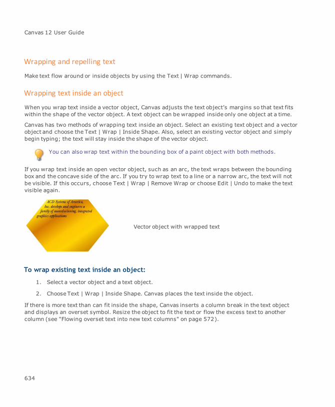
Canvas 12 User Guide
Wrapping and repelling text
Make text flow around or inside objects by using the Text | Wrap commands.
Wrapping text inside an object
When you wrap text inside a vector object, Canvas adjusts the text object’s margins so that text fitswithin the shape of the vector object. A text object can be wrapped inside only one object at a time.
Canvas has two methods of wrapping text inside an object. Select an existing text object and a vectorobject and choose the Text | Wrap | Inside Shape. Also, select an existing vector object and simplybegin typing; the text will stay inside the shape of the vector object.
You can alsowrap text within the bounding box of a paint object with both methods.
If you wrap text inside an open vector object, such as an arc, the text wraps between the boundingbox and the concave side of the arc. If you try to wrap text to a line or a narrow arc, the text will notbe visible. If this occurs, choose Text | Wrap | Remove Wrap or choose Edit | Undo tomake the textvisible again.
Vector object with wrapped text
To wrap existing text inside an object:
1. Select a vector object and a text object.
2. Choose Text | Wrap | Inside Shape. Canvas places the text inside the object.
If there is more text than can fit inside the shape, Canvas inserts a column break in the text objectand displays an overset symbol. Resize the object to fit the text or flow the excess text to anothercolumn (see "Flowing overset text into new text columns" on page 572).
634

Chapter 6: Text And Typography
To type new text inside an object:
1. Activate the Auto type into object preference (see "Setting preferences" on page 97).
2. Select a vector object.
3. Begin typing. Canvas adjusts margins so that text you type remains within the left and rightborders of the object.
If the object is too small to contain all the text you type, the text object extends below the object.Resize the object to fit the text or resize the text object to fit the shape, and then flow any excess textto another column.
Center-justified text wrapped inside anoval
Removing wrap effects
Restore text margins to the standard rectangular shape by choosing Text | Wrap | Remove Wrap.
To remove effects, also use the Undos palette or keyboard command: Ctrl+Z.
To remove a wrap effect:
Select a wrapped text object. Choose Text | Wrap | Remove Wrap.
Repelling text from objects
Tomake text flow around an object, apply a repel setting to the object. You also can set the amount ofspace between the object and text it repels.
635
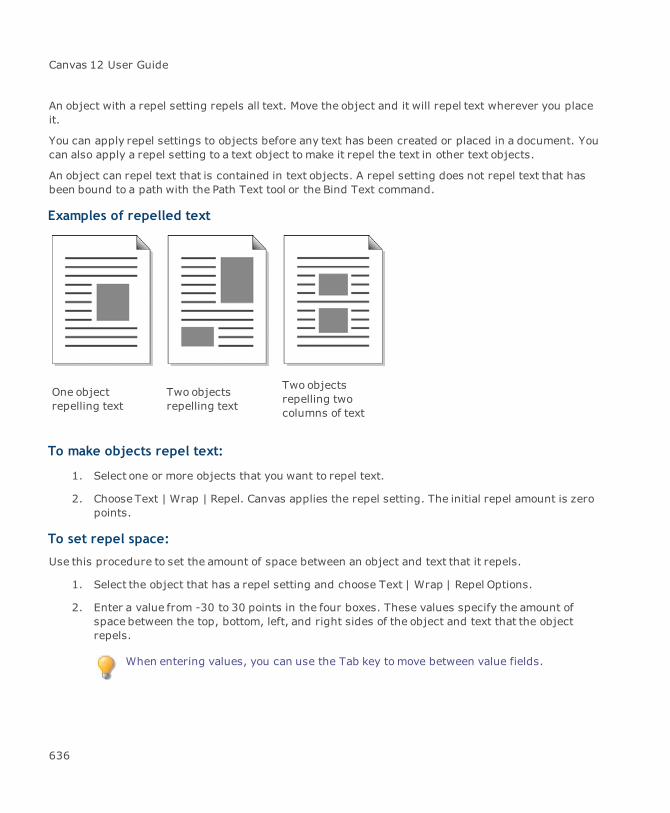
Canvas 12 User Guide
An object with a repel setting repels all text. Move the object and it will repel text wherever you placeit.
You can apply repel settings to objects before any text has been created or placed in a document. Youcan also apply a repel setting to a text object to make it repel the text in other text objects.
An object can repel text that is contained in text objects. A repel setting does not repel text that hasbeen bound to a path with the Path Text tool or the Bind Text command.
Examples of repelled text
One objectrepelling text
Two objectsrepelling text
Two objectsrepelling twocolumns of text
To make objects repel text:
1. Select one or more objects that you want to repel text.
2. Choose Text | Wrap | Repel. Canvas applies the repel setting. The initial repel amount is zeropoints.
To set repel space:
Use this procedure to set the amount of space between an object and text that it repels.
1. Select the object that has a repel setting and choose Text | Wrap | Repel Options.
2. Enter a value from -30 to 30 points in the four boxes. These values specify the amount ofspace between the top, bottom, left, and right sides of the object and text that the objectrepels.
When entering values, you can use the Tab key tomove between value fields.
636
Chapter 6: Text And Typography
3. Click Apply to view the effect of the current settings. Click OK to apply the settings and closethe dialog box.
To remove a repel setting:
Select an object that you do not want to repel text. Choose Text | Wrap | Remove Wrap. Canvasremoves the repel setting from the selected object.
Binding text to vector objects
Bind the baseline of text to the path of most types of vector objects. Canvas adjusts the verticalorientation of each character to match the path.
Depending on how you want to bind text, you can choose Effects | Bind Text or the Path Text tool. TheBind Text command lets you bind existing text to an object, and the Path Text tool lets you type newtext directly on the path of a selected object.
Canvas lets you bind multiple text objects to one vector object, but a text object can bind to only onevector object at a time. Also, you can bind only one text object to a vector object using the Path Texttool. To bind additional text objects to the same vector object after using the Path Text tool, you mustcreate a separate text object and choose Effects | Bind Text.
Position and direction of bound text
Whether you use the Bind Text command or Path Text tool, the location where you click the pointerdetermines the alignment position.
637

Canvas 12 User Guide
This text is center-justified. The I-beampointer (which appears after choosing theBind Text command or the Path Text tool)determines where text binds. In theexample, the pointer is clicked in theupper-right quadrant of the oval. The insetshows the bound text, centered around thepoint where the pointer was clicked.
For open-ended objects, such as arcs,bound text initially flows in the directionthe object was drawn. In this example, thearrows indicate the direction the arcs weredrawn. Text objects bound to these arcsfollow the direction of the arcs.
To bind existing text using a menu command:
1. Select a text object and vector object.
2. Choose Effects | Bind Text. When the pointer is on the edge of the selected object, thepointer becomes an I-beam.
3. Click to place the selected text on the path. Text aligns to the point where you click; e.g., ifthe text is center-justified, Canvas binds the text so that it is centered around the point youclick.
To type on a path using the Path Text tool:
1. Select the Path Text tool.
When the pointer is on the edge of an object, the pointer becomes a crosshair.
638
Chapter 6: Text And Typography
2. Click where you want to start typing on the path. An insertion point appears.
3. Begin typing. The text aligns to the location where you placed the insertion point and followsthe path of the object.
Working with bound text
Once you bind text, you can change its starting position, alignment, baseline position, and flowdirection. In addition, you can edit the shape and location of the vector object to which text is bound,and Canvas will fit the text to the new path.
You can also edit bound text by selecting the Path Text tool and clicking the text object, or by double-clicking a bound text object with a Selection tool. However, text editing might be difficult and slowwhile the text is bound to an object; you might want to remove the text bind, make changes, and re-bind the text.
Bound text and its binding object move together, just like grouped objects. However, unlike groupedobjects, you can select and change attributes (such as stroke and ink) individually for the text andthe object.
To position and align bound text:
Canvas has three Bind Position handles that you can drag to place text anywhere on, above, or belowan object. The handles appear when you select a bound text object.
639
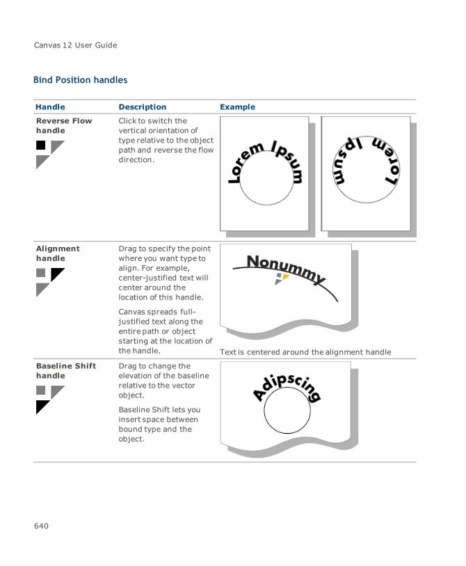
Canvas 12 User Guide
Bind Position handles
Handle Description Example
Reverse Flowhandle
Click to switch thevertical orientation oftype relative to the objectpath and reverse the flowdirection.
Alignmenthandle
Drag to specify the pointwhere you want type toalign. For example,center-justified text willcenter around thelocation of this handle.
Canvas spreads full-justified text along theentire path or objectstarting at the location ofthe handle. Text is centered around the alignment handle
Baseline Shifthandle
Drag to change theelevation of the baselinerelative to the vectorobject.
Baseline Shift lets youinsert space betweenbound type and theobject.
640
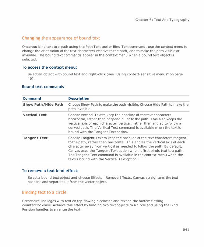
Chapter 6: Text And Typography
Changing the appearance of bound text
Once you bind text to a path using the Path Text tool or Bind Text command, use the context menu tochange the orientation of the text characters relative to the path, and tomake the path visible orinvisible. The bound text commands appear in the context menu when a bound text object isselected.
To access the context menu:
Select an object with bound text and right-click (see "Using context-sensitive menus" on page46).
Bound text commands
Command Description
Show Path/Hide Path ChooseShow Path tomake the path visible. Choose Hide Path to make thepath invisible.
Vertical Text ChooseVertical Text to keep the baseline of the text charactershorizontal, rather than perpendicular to the path. This also keeps thevertical axis of each character vertical, rather than angled to follow acurved path. The Vertical Text command is available when the text isbound with the Tangent Text option.
Tangent Text Choose Tangent Text to keep the baseline of the text characters tangentto the path, rather than horizontal. This angles the vertical axis of eachcharacter away from vertical as needed to follow the path. By default,Canvas uses the Tangent Text option when it first binds text to a path.The Tangent Text command is available in the context menu when thetext is bound with the Vertical Text option.
To remove a text bind effect:
Select a bound text object and choose Effects | Remove Effects. Canvas straightens the textbaseline and separates it from the vector object.
Binding text to a circle
Create circular logos with text on top flowing clockwise and text on the bottom flowingcounterclockwise. Achieve this effect by binding two text objects to a circle and using the BindPosition handles to arrange the text.
641
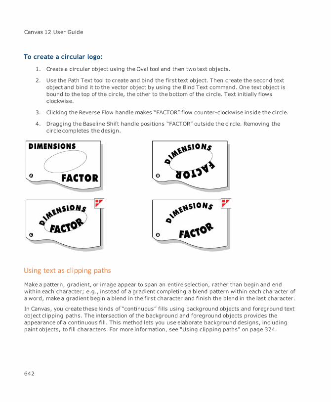
Canvas 12 User Guide
To create a circular logo:
1. Create a circular object using the Oval tool and then two text objects.
2. Use the Path Text tool to create and bind the first text object. Then create the second textobject and bind it to the vector object by using the Bind Text command. One text object isbound to the top of the circle, the other to the bottom of the circle. Text initially flowsclockwise.
3. Clicking the Reverse Flow handle makes “FACTOR” flow counter-clockwise inside the circle.
4. Dragging the Baseline Shift handle positions “FACTOR” outside the circle. Removing thecircle completes the design.
Using text as clipping paths
Make a pattern, gradient, or image appear to span an entire selection, rather than begin and endwithin each character; e.g., instead of a gradient completing a blend pattern within each character ofa word, make a gradient begin a blend in the first character and finish the blend in the last character.
In Canvas, you create these kinds of “continuous” fills using background objects and foreground textobject clipping paths. The intersection of the background and foreground objects provides theappearance of a continuous fill. This method lets you use elaborate background designs, includingpaint objects, to fill characters. For more information, see "Using clipping paths" on page 374.
642

Chapter 6: Text And Typography
To use text as a clipping path:
1. Position the text object in front of the object to be clipped, and then select both objects.
2. ChooseObject | Clipping Path | Make.
Text object in front of image object
Clipping path appears filled with imageobject
Applying vector effects to type
Apply the following vector effects to text objects: Envelope, Extrude, Rotate, Freeform rotate andskew, Flip, Shadow, and Path editing.
Use effects to add dimension to text objects and create striking designs. This section describesbriefly how to apply each of these effects (see "Vector effects" on page 371).
Before applying vector effects to type
Depending on the number and kind of effects you apply to text, you might not be able to edit the textafterwards; e.g., you can edit text after rotating and skewing, but if you also extrude the text, Canvasconverts the text to vector objects. In addition, depending on the speed of your system, editingrotated and skewed text might be slow. Therefore, you might want to finish all text editing,formatting, and layout before applying effects.
Freeform and rotate effects
In Canvas, you can place a text object in freeformmode and then drag any of the hollow selectionhandles of the bounding box to rotate and skew text. Choose Effects | Rotate Right/Left | Other toperform exact rotations.
643
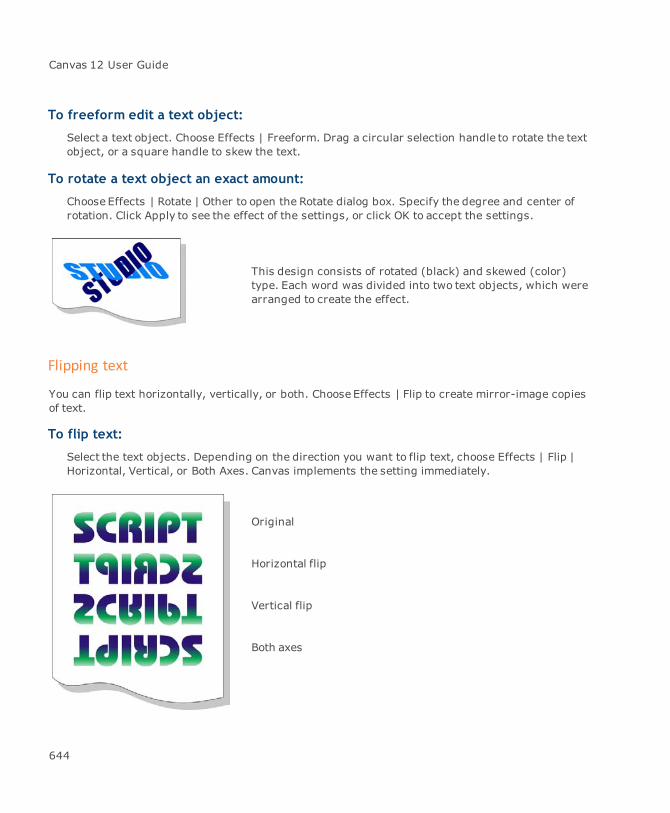
Canvas 12 User Guide
To freeform edit a text object:
Select a text object. Choose Effects | Freeform. Drag a circular selection handle to rotate the textobject, or a square handle to skew the text.
To rotate a text object an exact amount:
Choose Effects | Rotate | Other to open the Rotate dialog box. Specify the degree and center ofrotation. Click Apply to see the effect of the settings, or click OK to accept the settings.
This design consists of rotated (black) and skewed (color)type. Each word was divided into two text objects, which werearranged to create the effect.
Flipping text
You can flip text horizontally, vertically, or both. Choose Effects | Flip to create mirror-image copiesof text.
To flip text:
Select the text objects. Depending on the direction you want to flip text, choose Effects | Flip |Horizontal, Vertical, or Both Axes. Canvas implements the setting immediately.
Original
Horizontal flip
Vertical flip
Both axes
644
Chapter 6: Text And Typography
Shadow effects
In Canvas, when you apply a shadow to text, the shadow is a separate object that you can color, edit,and apply effects to independently of the original text object. By applying the right combination ofeffects, you can achieve oblique shadows and other lighting effects.
Since Canvas creates a separate object for the shadow, changes to the original text object do notchange the shadow. Finalize text before applying shadows to ensure that the text is the same for bothobjects.
To create a shadow:
1. Select the text objects to which you want to apply shadows.
2. Choose Effects | Shadow to open the Shadow dialog box.
3. Specify Object or Image. Image activates the ImageOptions area.
4. Specify the offset amounts as well as a color for the shadow.
5. In the Image Options area, specify Gaussian Blur, mode, resolution, and anti-alias.
6. Canvas creates the shadows and arranges them behind the original text objects.
Text shadow effects
Combine Canvas effects to create different types of shadows.
An object shadow, slightly offset and shaded black.
A black image shadow, slightly offset with Gaussian Blur
The shadow object was skewed to create an oblique shadow.
This example consists of three objects: the original text object, a slightly offset shadow, and anoblique shadow.
This example consists of three objects: the original text object, a slightly offset shadow object, and aduplicated shadow object. The duplicate has been flipped, skewed, and filled with a gradient ink.
Envelope text effects
Use the Envelope effect to warp and distort type to create new character forms and stretch text likerubber. When you apply this effect to a text object, you can drag selection handles to reshape text.Depending on the type of envelope, text stretches in different ways. Using this effect, addperspective to text or simulate stretching type around a 3-D object (see "Enveloping objects" on page384 for more information about the Envelope effect).
645

Canvas 12 User Guide
You cannot edit text after applying an envelope effect. however, you can apply an extrusionto an enveloped object.
To edit the envelope of a text object:
1. Select a text object and choose Effects | Envelope.
2. Choose a type of envelope effect in the pop-up menu and click Apply.
3. Drag the envelope handles to reshape the text.
Extruding text
Extrude text and add lighting effects to make text appear three-dimensional. As with vector objects,you can rotate and scale extruded text to change the apparent depth, size, and orientation. For text,you can only use the Parallel option in the Extrude palette.
You cannot edit text after applying an envelope effect.
Canvas removes stroke and fill attributes before extruding text because they can interfere with thethree-dimensional effect. Add color to extruded objects by choosing a fill ink from the Presets paletteand a color for the light source in the Extrude palette (see "Extruding objects" on page 387 for moreinformation about the Extrude effect).
Extruded text with lighting effects
646
Chapter 6: Text And Typography
To extrude text:
1. Select a text object and choose Effects | Extrude to open the Extrude palette.
2. Choose Parallel in the menu.
3. Configure the settings and click Apply.
4. Use the extrusion handles to shape and rotate the text.
Converting text to paths
Canvas can create path outlines of characters so you can edit the shape of each character. Once youconvert text to paths, Canvas treats the paths as objects. You cannot edit the objects as text (changefont type, type size, or run spell check, etc.).
To convert text to paths:
1. Select a text object and choose Path | Convert to Paths. If the text object contains multiplecharacters, Canvas creates a grouped object.
2. To ungroup the object and edit individual characters, choose Object | Ungroup. You can alsouse the Direct Selection tool to select individual objects without ungrouping.
3. Double-click an object to place it in path edit mode. To put several shapes in path edit modeat the same time, select multiple objects and choose Path | Edit Path.
4. Use path-editing techniques to change the object, and then press Esc to exit edit mode.
Typing text on paths
Use the Path Text tool to type text so it follows the path of a vector object, such as a circle, polygon,or open curve. You can also use the tool to create text that flows along multiple paths.
To type text on a path:
1. Select the Path Text tool.
In the document window, the pointer is an arrow. The arrow changes to an I-beam when youpoint to a vector object path.
647
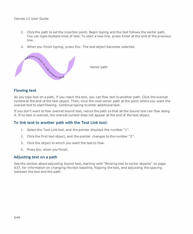
Canvas 12 User Guide
2. Click the path to set the insertion point. Begin typing and the text follows the vector path.You can typemultiple lines of text. To start a new line, press Enter at the end of the previousline.
3. When you finish typing, press Esc. The text object becomes selected.
Vector path
Flowing text
As you type text on a path, if you reach the end, you can flow text to another path. Click the oversetsymbol at the end of the text object. Then, click the next vector path at the point where you want theoverset text to start flowing. Continue typing to enter additional text.
If you don’t want to flow overset bound text, resize the path so that all the bound text can flow alongit. If no text is overset, the overset symbol does not appear at the end of the text object.
To link text to another path with the Text Link tool:
1. Select the Text Link tool, and the pointer displays the number “1”.
2. Click the first text object, and the pointer changes to the number “2”.
3. Click the object to which you want the text to flow.
4. Press Esc when you finish.
Adjusting text on a path
See the section about adjusting bound text, starting with "Binding text to vector objects" on page637, for information on changing the text baseline, flipping the text, and adjusting the spacingbetween the text and the path.
648
Chapter 7: Sprite Technology

Canvas 12 User Guide
SpriteEffects
In Canvas, you could always modify objects with image-editing techniques — if you converted theobjects to images; however, you lost the ability to edit vector paths and text. Also, applying filtersand adjustments would change an image permanently. The Canvas SpriteEffects technology lets youapply image filters and adjustments to vector objects, images, text, and grouped objects.
You can apply effects temporarily, adjust effects settings, change the order of effects, and hide orremove effects individually. You don’t have to use Undo or save intermediate versions to preserve anoriginal illustration, since objects remain editable. You can still edit object paths, insert and deletetext, as well as change inks and strokes.
When SpriteEffects are printed or exported to file formats outside of Canvas, the effects are renderedas images. This is like taking a snapshot of the objects and printing the resulting image. In yourCanvas documents, the objects keep their original editing features.
Before SpriteEffects, commands such as Blur, Hue/Saturation, Invert, Emboss, Twirl, and manyothers could be applied to paint objects (images) only. SpriteEffects technology offers new powerand flexibility for creative art, technical illustration, and graphics production.
Introduction to SpriteEffects
SpriteEffects technology was introduced to allow for the easy creation and placement of fully-editabletransparency effects to text, images, and vector objects within Canvas. Remember all SpriteEffectscan be edited and reapplied at will at any time during the design process.
Using SpriteEffects
There are twoways to use SpriteEffects:
Apply effects directly to objects: Apply image effects and adjustment commands directlyto vector, text, paint, and group objects. You could apply the Blur command to a text object,then use the Hue/Saturation command to highlight the text edges with color for example.When you apply effects directly, an entire object, including its fill ink, pen ink, and stroke, isaffected.
Apply effects to lens objects:Create a lens object from a vector or text object. Then, applyeffects to the lens. The effects will appear on objects that are viewed through the lens.Lenses can magnify objects and view objects in other locations. If you move the viewpoint ofa lens, whatever is behind the viewpoint will appear in the lens. If you move the lens, theviewpoint can remain fixed or movewith the lens. See "Creating a lens" on page 659.
650

Chapter 7: Sprite Technology
Applying an effect
Because many types of filters and adjustments can be applied through SpriteEffects, generalprocedures are given here. You can locate specific information for effects commands by looking upthe commands in the index. When a vector or text object is selected, the SpriteEffects icon andSpriteEffects menu appear in the Properties bar.
To apply an effect:
1. Select an object or a lens.
2. Do one of the following:
In the Properties bar, select an effect from the SpriteEffects drop-down list.
ChooseObject | SpriteEffects | Add an Effect, then select an effect.
In the SpriteEffects palette, click the New Effect icon, select an effect from the drop-downlist, then click OK.
3. If a dialog box appears, select the settings you want to use, then click OK.
You can applymultiple effects by repeating this task as many times as necessary.
Using plug-in filters with SpriteEffects
You can also use Plug-in filters with SpriteEffects. Plug-ins must be Adobe Photoshop 4.0. compatibleand also support Photoshop Actions.
Plug-ins can be installed by copying them to the Plug-ins folder in the Canvas Tools folder. Forinformation on settings and options for a plug-in, refer to the documentation from themanufacturer.
Effects commands in the Image | Filter and Image | Adjust submenus are available fortraditional image editing. These commands are not available when other types of objects areselected.
Using the SpriteEffects palette
The SpriteEffects palette is the control center for applying effects, creating lenses, and editingeffects on objects. All SpriteEffects features are available in the palette, except Attach and Detach,
651

Canvas 12 User Guide
which are in the Object | SpriteEffects submenu. If an object is selected, its SpriteEffects settingsare shown in the palette. When no object is selected, the controls in the palette are not available.
To display the SpriteEffects palette:
Do one of the following:
ChooseWindow | Palettes | SpriteEffects.
In the Properties bar, click the SpriteEffects icon.
You can keep the palette open while you work or dock it on the Docking bar.
Using the effects list
When you select an object that has effects, use the list at the top of the SpriteEffects palette toarrange the order of effects. You can also show or hide effects, and change themask setting.
Effects that are applied to the selected object are listed in order of application, with the first effect atthe top. If no effects appear in the list, the selected object has none, or more than one object (or noobject) is selected.
To modify an effect’s settings:
1. In the SpriteEffects palette, select the effect name.
2. Do one of the following:
Choose Edit Effect Settings from the palette menu.
Double-click the effect name in the Effects list.
3. Use the dialog box to adjust the settings for the effect.
4. Click OK to apply the current settings.
Some filter and adjustment commands (including Blur, Desaturate, Invert, and Sharpen) do not haveeditable settings, so choosing Edit Effect Settings or double-clicking the effect does nothing.
To arrange effects:
In the SpriteEffects palette, drag an effect up or down in the list to change the order in whicheffects are applied.
652

Chapter 7: Sprite Technology
To show and hide effects:
1. Select the object whose effects you want to hide/show.
2. In the SpriteEffects palette, click the eye symbol to hide/show the effect.
Hiding an effect temporarily removes the effect from the object. Showing an effect re-appliesthe effect to the selected object.
To duplicate or remove effects:
Use the SpriteEffects palette to duplicate or remove effects that have been applied to a selectedobject. Removing an effect deletes it from the Effects list.
If you just want to temporarily hide an effect, click the eye symbol in the Effects list.
1. Select the object whose effects you want to edit.
2. In the SpriteEffects palette, do any of the following:
Duplicate Effect: Select an effect in the list and choose Duplicate Effect in the palettemenu.
Delete Effect: To remove an effect, select the effect in the list. Click the trash can orchooseDelete Effect in the palette menu.
Clear All Effects: To remove all effects from the selected object, choose Clear All Effectsin the palette menu.
To add effects:
Each effect that you apply appears in the Effects list.
Select an object that has no effects, one that has effects, or a lens.
1. Select an object to which you want to apply effects.
2. In the SpriteEffects palette, click the New Filter Effect button or chooseNew Effect in thepalette menu.
3. In the dialog box, select an effect command from the menu and click OK. If there are nooptions for the command, Canvas applies the effect.
4. If there are options for the command, a dialog box opens. Configure the options and click OK.
653
Canvas 12 User Guide
To save effects:
You can save effects that have been applied to an object as a set. After saving an effects set, you canapply the set to other objects.
1. Open the SpriteEffects palette.
2. Select an object or lens that has effects you want to save.
3. ChooseSave Effects from the SpriteEffects palette menu.
4. In the dialog box, enter a name and select a location to save the effects set.
5. Click Save to save the set in a file.
To apply saved effects:
1. Open the SpriteEffects palette.
2. Select the object you want to apply the effects set to. You can select an object with noeffects, one that has effects, or a lens.
3. Do one of the following:
To replace the selected object’s effects with the effects set: Choose Load Effects in thepalette’s menu.
To add the effects set to the effects on the selected object: Choose Append Effects in thepalette’s menu.
4. In the dialog box, select an effects set file and click Open. Canvas applies the effects to theselected object.
Pasting effects
You can use the Paste Attributes command to transfer effects from one object to another.
To paste SpriteEffects:
1. Copy an object that has effects to the Clipboard.
2. Select an object to which you want to transfer the effects.
3. Choose Edit | Paste Attributes.
4. In the Paste Attributes dialog box, select the SpriteEffects option and click OK. Canvas willapply the effects (except lens settings) to the selected object.
654
Chapter 7: Sprite Technology
Detaching and attaching SpriteEffects
The Detach and Attach commands transfer filters and adjustments between objects and lenses.
Detach: Removes effects from a selected object and applies the effects to a new lens that isthe same size as the object’s bounding box.
Attach: Applies effects from a lens directly to an object. Attaching is a way to apply multipleeffects to an object at once.
You can also use the Load Effects, Save Effects, and Append Effects commands in theSpriteEffects palette to transfer sets of effects.
To detach effects:
1. Select an object (not a lens) that has effects.
2. ChooseObject | SpriteEffects | Detach.
3. Canvas removes the object’s effects and applies them to a new lens, which appears offsetfrom the original object and is selected.
To attach effects:
1. Select a lens object that has effects you want to apply, and a non-lens object to receive theeffects. The objects do not have to be the same size or overlap and either one can be first inthe stacking order.
2. ChooseObject | SpriteEffects | Attach. Canvas applies the effects, except the lensproperties, to the selected object. The original lens object is not changed.
SpriteEffects options
In the SpriteEffects palette, you can set the color mode, resolution, and anti-aliasing for the effectsapplied to a selected object. These options control how SpriteEffects are rendered for printing andexport, as well as the display of SpriteEffects in Canvas.
When you change a setting, the change is applied immediately to the selected object.
Mode
From the Modemenu, select the color mode to use for rendering SpriteEffects.
655
Canvas 12 User Guide
The Mode option is used for rendering all the effects applied to an object; e.g., if you chooseGrayscale, the object and effects applied to it will appear in gray shades on screen and when theobject is printed or exported.
Select a mode that is appropriate for themedium you use. RGB is best for Web graphics, screendisplay, and output to a film recorder. CMYK is appropriate for process-color printing and colorseparations for commercial printing. Grayscale is appropriate for black-and-white publishing.
None is available in the mode menu only when the selected object is a lens that has no effects appliedto it; however, the lens can have a magnification value and remote viewpoint.
If you select None, the lens object is not rendered for printing or export. This can be more efficientand produce better output when a lens displays vector objects or high-resolution images. This optionis useful if you use lenses without effects to show close-ups or call-outs of diagrams.
Resolution
Enter the resolution in ppi for rendering SpriteEffects. A high resolution makes effects appearsmoother; however, higher resolution requires morememory and slows down printing.
For Web graphics and screen display, 72 ppi is recommended. For office printing, 100 to 200 ppi isusually sufficient. For commercial printing, a range of 150 to 300 ppi is recommended for halftoneimages, depending on the paper and press requirements.
Anti-Alias
Select this option if you want to smooth the edges of objects in the rendering of SpriteEffects.
Selections masks
In the Effects list, a symbol to the left of each effect name shows the state of the selection mask forthe effect. You can click the symbol to toggle themask on ( ) and off ( ).
An active selection mask defines a selection for an effect. The selection will include objects, notempty space. The mask can preserve transparent areas, such as empty space in a group object, andspace between text characters.
When the selection mask is on, the effect is based on the selection area. When the selection mask isoff, the effect is based on the entire bounding box area; e.g., if you apply the Add Noise command toa circle, the selection includes only the circle, so the noise affects only the circle if the mask is on. Ifthemask is off, the noise appears in the entire bounding box area.
656
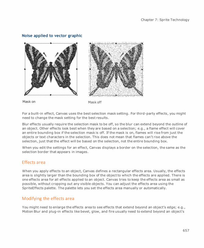
Chapter 7: Sprite Technology
Noise applied to vector graphic
Mask on Mask off
For a built-in effect, Canvas uses the best selection mask setting. For third-party effects, you mightneed to change themask setting for the best results.
Blur effects usually require the selection mask to be off, so the blur can extend beyond the outline ofan object. Other effects look best when they are based on a selection; e.g., a flame effect will coveran entire bounding box if the selection mask is off. If themask is on, flames will rise from just theobjects or text characters in the selection. This does not mean that flames can’t rise above theselection, just that the effect will be based on the selection, not the entire bounding box.
When you edit the settings for an effect, Canvas displays a border on the selection, the same as theselection border that appears in images.
Effects area
When you apply effects to an object, Canvas defines a rectangular effects area. Usually, the effectsarea is slightly larger than the bounding box of the object to which the effects are applied. There isone effects area for all effects applied to an object. Canvas tries to keep the effects area as small aspossible, without cropping out any visible objects. You can adjust the effects area using theSpriteEffects palette. The palette lets you set the effects area manually or automatically.
Modifying the effects area
You might need to enlarge the effects area to see effects that extend beyond an object’s edge; e.g.,Motion Blur and plug-in effects like bevel, glow, and fire usually need to extend beyond an object’s
657

Canvas 12 User Guide
outline. Also, if text characters extend outside the text object border, an effect applied to the textcould be cut off.
If you make the effects area smaller than an object’s bounding box, the object and the effects will becropped by the effects area border.
To size the effects area automatically:
1. Select the object whose effects area you want to adjust.
2. In the SpriteEffects palette, click the smart-crop icon.
3. Click OK when the prompt appears. Canvas estimates the correct size of the effects area andmakes it as small as possible.
Effects area box
To size the effects area manually:
Some effects need to extend far outside an object’s bounding box. In these cases, the auto-sizeoption might not extend the effects area far enough. If this happens, you can enlarge the effects areayourself.
1. Select the object whose effects area you want to adjust.
2. In the SpriteEffects palette, click the crop icon.
A box appears on the selected object. The box indicates the effects area and has hollowhandles (the object’s bounding box has solid handles).
3. Drag a handle to enlarge or reduce the effects area. When the box is the size you want, clickinside it.
To size the effects area precisely:
You can enter values to precisely size the effects area.
658
Chapter 7: Sprite Technology
1. Select the object whose effects area you want to adjust.
2. In the SpriteEffects palette, chooseSize of Effects Area from the palette menu.
3. In the Effect Dimensions dialog box, do one of the following:
Set the size of the effects area by entering the distance from the rulers’ zero point to theleft, top, right, and bottom sides of the effects area rectangle.
Click a button to enlarge ( ) or reduce ( ) the size of the effects area. When youclick a button, the distance values in the text boxes show the new effects area size.
4. Click OK to apply the settings.
Lens effects
You can apply effects to a lens the same as you apply effects to other objects. Lens objects let youlimit an effect to a particular region of an illustration, or they let you magnify an area when you wantto show a detailed view. The default lens effect is normal (100%) magnification, but you can changethis if you want to see a magnified view. You can also change the viewpoint of what is displayed in thelens. By default the viewpoint is the center of the lens. If you want to offset the lens from whatever isdirectly behind it, you can change the viewpoint.
Creating a lens
You can create a lens from any object (except a lens). If you want to preserve an object, make a copyand convert the copy to a lens. Fill inks are removed when vector or text objects are converted tolenses. The stroke on a lens is not affected by the effects applied to the lens.
To create a lens object:
1. Create an object to use as a lens. You can create a new object or copy an existing object.
Fill inks are removed when vector or text objects are converted to lenses.
2. Select the object you want to use as a lens.
3. Do one of the following:
In the Properties bar, click the Make Lens button.
ChooseObject | Convert to Lens.
659
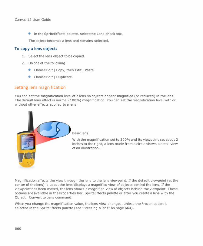
Canvas 12 User Guide
In the SpriteEffects palette, select the Lens check box.
The object becomes a lens and remains selected.
To copy a lens object:
1. Select the lens object to be copied.
2. Do one of the following:
Choose Edit | Copy, then Edit | Paste.
Choose Edit | Duplicate.
Setting lens magnification
You can set the magnification level of a lens so objects appear magnified (or reduced) in the lens.The default lens effect is normal (100%) magnification. You can set themagnification level with orwithout other effects applied to a lens.
Basic lens
With the magnification set to 300%and its viewpoint set about 2inches to the right, a lens made from a circle shows a detail viewof an illustration.
Magnification affects the view through the lens to the lens viewpoint. If the default viewpoint (at thecenter of the lens) is used, the lens displays a magnified view of objects behind the lens. If theviewpoint has been moved, the lens shows a magnified view of objects behind the viewpoint. Theseoptions are available in the Properties bar, SpriteEffects palette or after you create a lens with theObject | Convert to Lens command.
When you change themagnification value, the lens view changes, unless the Frozen option isselected in the SpriteEffects palette (see "Freezing a lens" on page 664).
660

Chapter 7: Sprite Technology
To set magnification:
1. Select the lens object.
2. Do one of the following:
In the Properties bar, enter the magnification value in the Lens Mag text box.
In the SpriteEffects palette, enter the magnification value in the Mag text box.
Lens object settings (Properties bar)
Lens X/Y If Absolute is selected, these settings refer to the distance from therulers’ zero point to the viewpoint. If Relative is selected, these settingsrefer to the distance from the center of the lens to the viewpoint.
Choose Click this button when you want to click in the document to set theviewpoint for a lens.
Reset Click this button to reset the viewpoint to the center of the lens object.
Absolute or Relative Absolute refers to the distance from the rulers’ zero point to theviewpoint. Relative refers to the distance from the center of the lens tothe viewpoint.
Lens Mag Enter the magnification value in the text box.
Advanced Click this button to open the SpriteEffects palette.
Lens options (SpriteEffects palette)
Lens Select the Lens check box to create a lens.
Mag Enter a magnification value.
Frozen Freeze the lens view.
Viewpoint Viewpoint settings:
Absolute: Sets the viewpoint to an absolute position. If you movethe lens object, the viewpoint does not change.Relative: Sets the viewpoint to a position relative to the lensobject. If you move the lens object, the viewpoint changes.
661
Canvas 12 User Guide
Setting a lens viewpoint
The viewpoint of a lens is a point in the document that appears in the lens. The default viewpoint is atthe center of the lens, so the lens displays whatever is directly behind it. You can move the viewpointof a lens tomake any location appear in the lens, which is useful for displaying close-ups ofillustrations. The center of a lens is focused on the lens viewpoint. If you move the viewpoint, the newlocation appears centered in the lens object. The viewpoint of a lens can be set anywhere on the samepage, slide, sheet, or frame as the lens object. Lenses can display objects on all visible layers on thesame page, sheet, slide, or frame. Lenses do not display objects on other pages, sheets, slides, orframes.
You can set a viewpoint visually by clicking in the document, or precisely, by entering values for theAbsolute or Relative position.
To set a viewpoint visually:
1. Select the lens object.
2. In the Properties bar or SpriteEffects palette, select Relative or Absolute.
3. Click Choose.
4. Move the pointer in the document and click to set the viewpoint.
The area you click appears centered in the lens.
To set a viewpoint precisely:
1. Select the lens object.
2. In the Properties bar or SpriteEffects palette, select one of the following:
Absolute: Select Absolute and enter horizontal (X) and vertical (Y) distances from therulers’ zero point to the viewpoint; e.g., enter 0 in the X and Y boxes to set the viewpointat the zero point. If you move the lens object, the viewpoint does not change.
Relative: Select Relative and enter horizontal (X) and vertical (Y) distances from thecenter of the lens to the viewpoint. Positive values move the viewpoint down and right ofthe lens center. Negative values move the viewpoint up and left of the lens center; e.g., toset the viewpoint 1 ruler unit left of the lens center, enter -1 (X) and 0 (Y). If you movethe lens, the viewpoint changes.
662
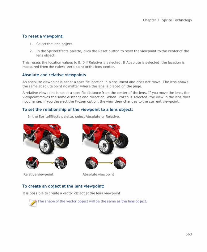
Chapter 7: Sprite Technology
To reset a viewpoint:
1. Select the lens object.
2. In the SpriteEffects palette, click the Reset button to reset the viewpoint to the center of thelens object.
This resets the location values to 0, 0 if Relative is selected. If Absolute is selected, the location ismeasured from the rulers’ zero point to the lens center.
Absolute and relative viewpoints
An absolute viewpoint is set at a specific location in a document and does not move. The lens showsthe same absolute point nomatter where the lens is placed on the page.
A relative viewpoint is set at a specific distance from the center of the lens. If you move the lens, theviewpoint moves the same distance and direction. When Frozen is selected, the view in the lens doesnot change; if you deselect the Frozen option, the view then changes to the current viewpoint.
To set the relationship of the viewpoint to a lens object:
In the SpriteEffects palette, select Absolute or Relative.
Relative viewpoint Absolute viewpoint
To create an object at the lens viewpoint:
It is possible to create a vector object at the lens viewpoint.
The shape of the vector object will be the same as the lens object.
663
Canvas 12 User Guide
1. Select the lens object and choose a viewpoint.
2. In the Properties bar, click the Advanced button.
3. In the SpriteEffects palette, select Create Object at ViewPoint from the palette menu.
You can modify the inks and strokes of the new object and also apply any vector effect.
Lenses and stacking order
The view through a lens depends on the stacking order of the lens, as well as the position of theviewpoint.
Only objects that are behind a lens in the stacking order can be seen through the lens. A lens and itsviewpoint are at the same level in the stacking order.
Use the stacking order to change a lens view. Send a lens to the back of the stack so nothingappears in it. Bring it to the front so all the objects at the viewpoint appear in the lens.
Due to the stacking order, objects that you create after you create a lens cannot appear in the lens.Also, objects that you move to the front of the stack after you create a lens cannot appear in the lens.
You can use a lens to display layered views; e.g., you can draw a map and create a lens to show aclose-up of an area. If you add text after you create the lens, the text is higher in the stacking order.The text will not appear in the lens close-up of the map.
Freezing a lens
Select the Frozen check box in the SpriteEffects palette to freeze the lens object's current view; i.e.,the view won’t changeunless you deselect the Frozen check box. If you change the fill color of anobject, the lens will not show the change. Deselect the Frozen check box and Canvas updates the lensview.
Selecting Frozen overrides a lens relative viewpoint; the lens will show the same view after beingmoved. If you deselect Frozen, the lens will display the new viewpoint location.
The Frozen check box is only available if you select Grayscale, RGB, or CMYK from the Modemenu. If None is selected, the Frozen check box is not available.
Freezing a lens can avoid slow performance when you edit objects shown in a lens. When you finishediting, select the lens and deselect the Frozen check box to update the viewpoint.
664

Chapter 7: Sprite Technology
To freeze a lens:
1. Select the lens object.
2. In the SpriteEffects palette, select the Frozen check box.
3. Deselect the Frozen check box to show the new viewpoint.
Sharing documents with SpriteEffects
Since SpriteEffects are “live” effects that can be edited and updated, there are a few issues toconsider if you plan to share documents that contain SpriteEffects.
Effects that are applied to an object need to be available to other Canvas users if they share thedocument and need to edit the effects. If you use only built-in Canvas effects, this is not a problem. Ifyou use third-party plug-ins to apply effects, other users must have the same plug-ins installed.Without the plug-ins, they cannot edit effects applied in a Canvas document (see "Using plug-infilters with SpriteEffects" on page 651).
If you export a document using an image file format, the effects will be rendered into an image (asdescribed below), and the effects plug-ins will no longer be needed. Rendering is necessary becauseother file formats do not support SpriteEffects on objects.
Printing effects
When you print fromCanvas, preserving effects should not be a problem, as long as effects plug-insare available in Canvas when the document is printed. Whether you print directly to an output deviceor to a PostScript file, Canvas renders effects before printing. This is true unless, in the Print dialogbox, you set Transparency Rendering to “Don’t Render Transparent Objects.” When this option isselected, the only SpriteEffects that will be printed are lens objects that have no effects exceptmagnification and viewpoints.
Rendering effects
Preserve the appearance of effects by rendering objects before sharing a Canvas document.Rendering converts SpriteEffects and objects into static images.
Effects and objects are not editable after conversion to images.
You can use one of several methods to render SpriteEffects:
Use the Camera tool to select an area of an illustration to render.
Select objects that have effects, including lenses, and choose Image | Area | Render.
665
Canvas 12 User Guide
Save a document in an image file format, such as BMP, GIF, JPEG, PCX, or TIFF. Canvasrenders the document as an image before saving the file.
SpriteLayer effects
SpriteLayer effects let you apply transparency to objects and text. You can use SpriteLayertransparency to create collages, Web graphics, layered illustrations, “ghosted” text, vignettes, andtexturing.
Using the Transparency palette
The Transparency palette is a control center for SpriteLayer effects. The palette includes controlsand options for opacity, masks, transparency scope, and transfer modes.
In the Transparency palette, you can:
Use the Opacity slider to set the opacity of a selected object. The effect is the same as usingthe Opacity slider in the Properties bar (see "Opacity effects" on page 667).
Use the Scope options to control transparency effects in vector objects (see "Controlling thescope of transparency effects" on page 670).
Change the transfer mode of a selected object using the Transfer Mode menu (see "Usingtransfer modes" on page 685).
Apply channel masks and vector masks using the Maskmenu (see "Transparency masks" onpage 671).
The palette works with a single selected object. The controls in the palette are not availablewhen more than one object is selected.
You can also quickly apply SpriteLayer effects by using the controls in the Properties bar.
To open the Transparency palette:
Do one of the following:
ChooseWindow | Palettes | Transparency.
Object | SpriteLayers | Show Palette.
666
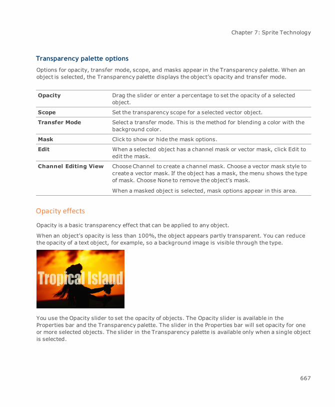
Chapter 7: Sprite Technology
Transparency palette options
Options for opacity, transfer mode, scope, and masks appear in the Transparency palette. When anobject is selected, the Transparency palette displays the object’s opacity and transfer mode.
Opacity Drag the slider or enter a percentage to set the opacity of a selectedobject.
Scope Set the transparency scope for a selected vector object.
Transfer Mode Select a transfer mode. This is themethod for blending a color with thebackground color.
Mask Click to show or hide the mask options.
Edit When a selected object has a channel mask or vector mask, click Edit toedit the mask.
Channel Editing View ChooseChannel to create a channel mask. Choose a vector mask style tocreate a vector mask. If the object has a mask, themenu shows the typeof mask. Choose None to remove the object’s mask.
When a masked object is selected, mask options appear in this area.
Opacity effects
Opacity is a basic transparency effect that can be applied to any object.
When an object’s opacity is less than 100%, the object appears partly transparent. You can reducethe opacity of a text object, for example, so a background image is visible through the type.
You use the Opacity slider to set the opacity of objects. The Opacity slider is available in theProperties bar and the Transparency palette. The slider in the Properties bar will set opacity for oneor more selected objects. The slider in the Transparency palette is available only when a single objectis selected.
667
Canvas 12 User Guide
Opacity affects the overall transparency of an object, so the Opacity slider is a master control for alltransparency effects applied to an object.
For example, you can use a channel mask tomake an oval vignette from a photograph. At the edge ofthe oval, the photograph becomes completely transparent. If you then reduce the opacity, the visiblepart of the image becomes partly transparent.
When an object’s opacity is less than 100%, anything in the background, including the illustrationarea, can affect the object’s appearance. The appearance of colors in an object can also be affectedby the object’s transfer mode (see "Using transfer modes" on page 685).
Defining opacity
“Transparency” and “opacity” are opposite terms that describe the ability to see through an object.
Greater transparencymeans it is easier to see through something; greater opacity means it is harderto see though it.
In percentages, 100%opacity equals 0% transparency. Those values describe objects you can’t seethrough. 1% opacity equals 99% transparency. Those values describe almost completely clearobjects.
All Canvas objects have an opacity. You can set opacity from 1% to 100% in 1% increments. Theopacity of a new object is 100%. When you copy an object, the copies have the same opacity as theoriginal object.
In this manual, the word “transparency” is often used as a general term for several related effects.The word “opacity” is used to refer to a specific effect and a specific property of objects.
In other words, an object’s “transparency” can result from various factors, including ink settings,the transfer mode, a channel mask, or another effect. An object’s “opacity,” on the other hand, is aspecific setting controlled by the Opacity slider.
668

Chapter 7: Sprite Technology
To set the opacity of an object:
You can use either the Opacity slider in the Properties bar or Transparency palette.
1. Select the object whose opacity you want to change.
2. Drag the Opacity slider to the left to decrease opacity; drag to the right to increase opacity.The opacity percentage appears at the right of the slider.
To set opacity for multiple objects:
Use the Opacity slider in the Properties bar to set the opacity for more than one object. Eachselected object will have the same opacity setting.
To adjust the opacity of a group object:
Use the Opacity slider in the Properties bar or in the Transparency palette, since a selected groupobject is considered a single object. When a group object is selected, changing the opacityapplies to the group as a whole. Objects that were opaque do not become transparent to otherobjects in the group if you reduce the opacity of the group object.
If you ungroup an object, the group opacity setting is removed and the opacity of eachseparate object is restored.
669
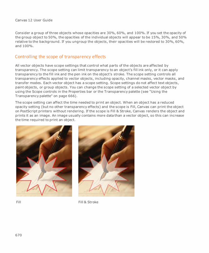
Canvas 12 User Guide
Consider a group of three objects whose opacities are 30%, 60%, and 100%. If you set the opacity ofthe group object to 50%, the opacities of the individual objects will appear to be 15%, 30%, and 50%relative to the background. If you ungroup the objects, their opacities will be restored to 30%, 60%,and 100%.
Controlling the scope of transparency effects
All vector objects have scope settings that control what parts of the objects are affected bytransparency. The scope setting can limit transparency to an object’s fill ink only, or it can applytransparency to the fill ink and the pen ink on the object’s stroke. The scope setting controls alltransparency effects applied to vector objects, including opacity, channel masks, vector masks, andtransfer modes. Each vector object has a scope setting. Scope settings do not affect text objects,paint objects, or group objects. You can change the scope setting of a selected vector object byusing the Scope controls in the Properties bar or the Transparency palette (see "Using theTransparency palette" on page 666).
The scope setting can affect the time needed to print an object. When an object has a reducedopacity setting (but no other transparency effects) and the scope is Fill, Canvas can print the objecton PostScript printers without rendering. If the scope is Fill & Stroke, Canvas renders the object andprints it as an image. An image usually contains more data than a vector object, so this can increasethe time required to print an object.
Fill Fill & Stroke
670
Chapter 7: Sprite Technology
To set an object’s transparency scope:
1. Select a vector object.
2. Select a Scope option in the Properties bar or Transparency palette:
To apply transparency effects to the entire object: Select Fill & Stroke.
To apply transparency effects to the object’s fill ink only: Select Fill.
Transparency masks
Transparencymasks let you create complex transparency effects. You can use transparencymaskswith vector, paint, text, and group objects.
Channel masks and vector masks are the two types of transparency masks available. You can applyeither mask type to vector, text, paint, and group objects.
An object can have only onemask, but it can have a mask along with other effects such asopacity and transfer mode.
Channel mask: Creates transparency based on a grayscale image. A channel mask is partof an object, the same way an image channel is part of a paint object. You can use paintingtools and image-editing techniques in a channel mask.
Vector mask: Creates transparency based on a vector gradient or the colors of a vectorobject. Vector masks can produce gradual transparency changes the same way that gradientinks produce gradual color changes. You can drag a tool to create radial, linear, elliptical,and rectangular vector masks, or you can use an object as a vector mask.
Changing the transparency preview
When you edit paint objects or channel masks, Canvas previews transparency effects according to apreference setting. You can temporarily change the preview when you are in channel mask editmode.
When you edit a channel mask with no preview, a checkerboard pattern lets you focus on thetransparent object. The checkerboard hides objects behind the transparent object, while showingthe transparent areas in the object you are editing.
In Total Preview mode, Canvas shows objects that are in front and in back of a paint objector channel mask you are editing.
671
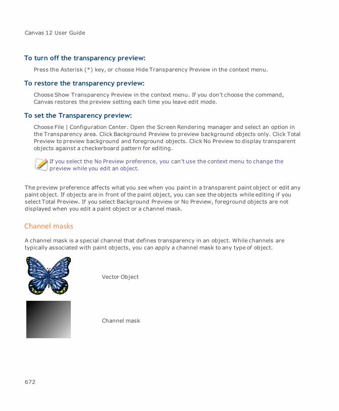
Canvas 12 User Guide
To turn off the transparency preview:
Press the Asterisk (*) key, or choose Hide Transparency Preview in the context menu.
To restore the transparency preview:
ChooseShow Transparency Preview in the context menu. If you don’t choose the command,Canvas restores the preview setting each time you leave edit mode.
To set the Transparency preview:
Choose File | Configuration Center. Open the Screen Rendering manager and select an option inthe Transparency area. Click Background Preview to preview background objects only. Click TotalPreview to preview background and foreground objects. Click No Preview to display transparentobjects against a checkerboard pattern for editing.
If you select the No Preview preference, you can’t use the context menu to change thepreview while you edit an object.
The preview preference affects what you see when you paint in a transparent paint object or edit anypaint object. If objects are in front of the paint object, you can see the objects while editing if youselect Total Preview. If you select Background Preview or No Preview, foreground objects are notdisplayed when you edit a paint object or a channel mask.
Channel masks
A channel mask is a special channel that defines transparency in an object. While channels aretypically associated with paint objects, you can apply a channel mask to any type of object.
Vector Object
Channel mask
672

Chapter 7: Sprite Technology
Transparency effect
Like an alpha channel in a paint object, a channel mask is basically a grayscale image. Channel maskscan be edited using image-editing tools and techniques, similar to alpha channels.
You can think of a channel mask as a template for transparency. The channel mask is the same sizeas themasked object and is aligned with it. In the case of a paint object, the channel mask has thesame resolution and number of pixels as the paint object.
Channel masks, like grayscale images, contain pixels that are assigned 256 possible lightness levels,or luminance values. Luminance values in a channel can range from 0 (black) to 255 (white).
In an alpha channel, luminance corresponds to selection intensity. In a channel mask, luminancevalues correspond to 256 levels of transparency, from 100% to 0% transparency, in the maskedobject. Black pixels (0 luminance) produce 100% transparency, while white pixels (255 luminance)produce 0% transparency.
Therefore, when you paint in a channel mask, painting with black produces clear areas and paintingwith white produces opaque areas in the masked object. Painting with gray produces partialtransparency relative to the gray value, with darker grays producing greater transparency thanlighter grays.
Black in a channel mask produces 100% transparency. A feathered edge produces partialtransparency.
Channel mask and paintobject
673
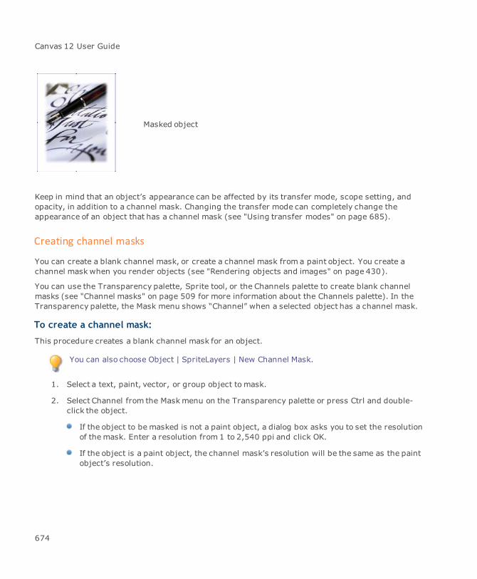
Canvas 12 User Guide
Masked object
Keep in mind that an object’s appearance can be affected by its transfer mode, scope setting, andopacity, in addition to a channel mask. Changing the transfer mode can completely change theappearance of an object that has a channel mask (see "Using transfer modes" on page 685).
Creating channel masks
You can create a blank channel mask, or create a channel mask from a paint object. You create achannel mask when you render objects (see "Rendering objects and images" on page 430).
You can use the Transparency palette, Sprite tool, or the Channels palette to create blank channelmasks (see "Channel masks" on page 509 for more information about the Channels palette). In theTransparency palette, the Mask menu shows “Channel” when a selected object has a channel mask.
To create a channel mask:
This procedure creates a blank channel mask for an object.
You can also choose Object | SpriteLayers | New Channel Mask.
1. Select a text, paint, vector, or group object to mask.
2. Select Channel from the Maskmenu on the Transparency palette or press Ctrl and double-click the object.
If the object to be masked is not a paint object, a dialog box asks you to set the resolutionof themask. Enter a resolution from 1 to 2,540 ppi and click OK.
If the object is a paint object, the channel mask’s resolution will be the same as the paintobject’s resolution.
674
Chapter 7: Sprite Technology
3. The object appears in channel mask edit mode, with the object visible and the channel maskselected. You can edit the channel mask with painting tools (see "Editing channel masks" onpage 676).
4. Press Esc to leave edit modewhen you finish.
When you create a new channel mask, the channel is filled with white pixels. At this point, thechannel mask produces no transparency because white pixels in the channel mask produce 0%transparency in themasked object. As you edit the channel, painting with gray produces partialtransparency, and painting with black produces 100% transparency.
To create a channel mask with the Sprite tool:
1. Use the Sprite tool to apply a channel mask to a text, vector, or image object.
2. Select the object to which you want to apply themask.
3.Select the Sprite tool and click on the selected object.
The object switches to image edit mode.
4. Oncemasked, apply transparency effects to the mask with Painting tools.
To set the channel mask scope:
When you apply a channel mask to a vector object, the channel mask affects the vector object’s fillink or fill ink and stroke (pen ink). To change the effect, change the Scope option in the Propertiesbar or Transparency palette (see "Controlling the scope of transparency effects" on page 670).
Masking with a paint object
You can create a channel mask by attaching a paint object to another object. If you have an existingpaint object that you want to use as a channel mask, it’s quicker to use this procedure than to use theChannels palette to place the paint object in a channel mask.
To attach a channel mask:
1. Place a paint object to use as a mask in front of the object to be masked. The two objects donot have to overlap or touch, but the paint object must be in front of the other object in thestacking order.
2. Select both objects.
3. ChooseObject | SpriteLayers | Attach Mask. Canvas creates a channel mask and both objectsremain selected. The original paint object is not changed.
675
Canvas 12 User Guide
If the paint object and the object to be masked aren’t the same size, Canvas scales the image of thepaint object to fit the masked object.
A channel mask created from a paint object is the same as any channel mask. You can edit it the sameas if you created a blank channel mask.
Like any other channel mask, a channel mask created from a paint object produces transparencyrelative to its gray values. If the channel mask is solid white, it creates no transparency; if it is solidblack, it creates 100% transparency and makes themasked object invisible.
Editing channel masks
You can use painting tools, filters, and image-editing commands tomodify the effect of a channelmask.
To edit a channel mask:
Place the masked object in channel mask edit mode.
Editing a channel mask is similar to editing a channel in a paint object. You can paint in the channelmask with shades of gray. You can make selections with selection tools, commands, and alphachannels. You can apply image-adjustment commands and filters to the entire channel mask or tojust the selected areas.
Options for channel mask editing
You can enter channel mask edit mode using any of the following methods.
With the mouse: Press Ctrl and double-click a masked object.
If the object doesn’t have a channel mask, this creates a channel mask and puts theobject in channel mask edit mode.
In the Transparency palette: Click the Edit button when a masked object is selected. Thisplaces an object with a channel mask in channel mask edit mode. If the object has a vectormask, it places the vector mask in edit mode.
In the Channels palette: When a paint object is in edit mode, click the channel mask toselect it for editing. When any other object is in channel mask edit mode, the channel maskis the only channel that can be selected.
676

Chapter 7: Sprite Technology
To edit a channel mask:
1. Select the masked object.
2. ChooseObject | SpriteLayers | Edit Channel Mask. The masked object appears in channelmask edit mode.
In this mode, the channel mask is active and the object is also visible. You can paint in thechannel or modify it to change the transparency of the underlying object.
3. Press Esc to leave edit modewhen you finish editing. The object remains selected.
Selecting views for channel mask editing
You have a choice of view when you edit an object’s channel mask. You can display the object and thechannel mask together, which shows you the overall effect of themask as you edit it. Or, you canhide the object to concentrate on the channel mask alone.
For information on selecting views with the Channels palette, see "Editing channel masks" on page510).
Selecting views in the Transparency palette
You can use the Transparency palette to change your view when you edit a channel mask. In channelmask edit mode, two buttons let you select editing views. Click the triangle at the lower left to expandthe palette if necessary to display the buttons.
To view the channel mask only:
In the Transparency palette, click Channel Mask Only. This is the same as hiding the “objectchannel” in the Channels palette.
To view the object and channel mask:
Click Image and Channel Mask. This is the same as making the “object channel” and thechannel mask visible in the Channels palette.
To remove a channel mask:
Removing a channel mask from an object removes the transparency effect produced by the channelmask.
1. Select the masked object.
2. ChooseObject | SpriteLayers | Detach Mask. Canvas removes the channel mask from theselected object.
677
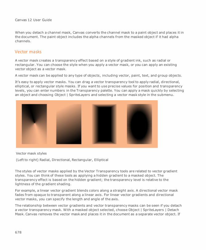
Canvas 12 User Guide
When you detach a channel mask, Canvas converts the channel mask to a paint object and places it inthe document. The paint object includes the alpha channels from the masked object if it had alphachannels.
Vector masks
A vector mask creates a transparency effect based on a style of gradient ink, such as radial orrectangular. You can choose the style when you apply a vector mask, or you can apply an existingvector object as a vector mask.
A vector mask can be applied to any type of objects, including vector, paint, text, and group objects.
It’s easy to apply vector masks. You can drag a vector transparency tool to apply radial, directional,elliptical, or rectangular style masks. If you want to use precise values for position and transparencylevels, you can enter numbers in the Transparency palette. You can apply a mask quickly by selectingan object and choosing Object | SpriteLayers and selecting a vector mask style in the submenu.
Vector mask styles
(Left to right) Radial, Directional, Rectangular, Elliptical
The styles of vector masks applied by the Vector Transparency tools are related to vector gradientstyles. You can think of these tools as applying a hidden gradient to a masked object. Thetransparency effect is based on the hidden gradient; the transparency level is relative to thelightness of the gradient shading.
For example, a linear vector gradient blends colors along a straight axis. A directional vector maskfades from opaque to transparent along a linear axis. For linear vector gradients and directionalvector masks, you can specify the length and angle of the axis.
The relationship between vector gradients and vector transparencymasks can be seen if you detacha vector transparencymask. With a masked object selected, choose Object | SpriteLayers | DetachMask. Canvas removes the vector mask and places it in the document as a separate vector object. If
678

Chapter 7: Sprite Technology
you examine this object, you see that it has a vector gradient. The gradient style is similar to thevector mask style. The vector gradient fades from black to white in the same way that the vector maskcaused the masked object to fade from transparent to opaque.
The relationship between vector masks and vector gradients also works in reverse; use a vectorgradient-filled object as a vector mask (see "Masking with a vector object" on page 681).
A vector mask is related to a vector gradient. If you detach a vector mask, you get an object with agradient. The grays in the gradient correspond to transparency levels in a masked object.
Original object Detached mask Masked object
Applying vector masks
You can apply a vector mask using the Vector Transparency tools. When an object is selected, youcan drag one of these tools near or over the object to apply a transparency effect.
The Vector Transparency tools provide the easiest way to create transparency effects such asvignettes (image that appear in ovals and other shapes) as well as linear, radial, or rectangularfades.
You can use the Transparency palette to apply vector transparency effects. When you use theTransparency palette, you can specify values for the position and intensity of the effect.
In the Transparency palette, the Mask menu shows the vector mask style when a selected object hasa vector mask.
679

Canvas 12 User Guide
To create a vector mask:
1. Select a text, paint, vector, or group object to mask.
2. Select a Vector Transparency tool. These tools are in the Transparency tools palette. Selectthe tool for the style of vector mask you want to apply: Radial, Directional, Rectangular, orElliptical.
3. Drag the tool near or over the selected object.
As you drag, a vector line or shape appears, whichrepresents the position of the vector transparency effect.
4. To adjust the effect, drag a handle to reposition the transparency vector.
5. Press Esc to leave edit mode.
To use the Transparency palette:
You can use the Transparency palette to apply a vector mask. To open the Transparency palette, see"Using the Transparency palette" on page 666.
1. Select an object to mask.
2. In the Transparency palette, choose a mask style in the Mask menu.
You can’t select “Object” in the menu. To use an object as a vector mask, see "Maskingwith a vector object" on page 681.
680
Chapter 7: Sprite Technology
3. To adjust the effect, drag the handles to reposition the transparency vector. When youfinish, press Esc to leave edit mode.
To set the vector mask scope:
When you apply a vector mask to a vector object, the mask affects the vector object’s fill ink or itsfill ink and stroke (pen ink). To change the effect, change the Scope option in the Properties bar orTransparency palette (see "Controlling the scope of transparency effects" on page 670).
Masking with a vector object
Create a vector mask by attaching a vector object to another object. Like other vector masks, a vectormask created from a vector object produces transparency relative to its color values; e.g., if thevector object that you attach is solid white, it creates no transparency; if it is solid black, it creates100% transparency, making themasked object invisible.
To attach a vector mask:
1. Place a vector object to use as a mask in front of the object to be masked. The two objects donot have to overlap or touch, but the vector objectmust be in front of the other object in thestacking order.
2. Select both objects.
3. ChooseObject | SpriteLayers | Attach Mask. Canvas creates a vector mask and both objectsremain selected. The original vector object is not changed.
If the vector object and the object to be masked aren’t the same size, Canvas scales the vector objectto fit the masked object.
Editing vector masks
You can edit vector masks that have been applied with the Vector Transparency tools, and maskscreated by attaching gradient-filled vector objects. Editing lets you change the boundary of theopaque and transparent areas of a mask. You can also add nodes for finer control of transparencylevels.
The handles correspond to the values in the Mask area in the Transparency palette. When you drag ahandle, the values are updated tomatch the new position.
To edit a vector mask:
1. Select the object and click Edit in the Transparency palette (see "Using the Transparencypalette" on page 666). Or, select the Vector Transparency tool that was used to apply the
681
Canvas 12 User Guide
mask.
2. Drag the vector mask editing handles to adjust the position and boundaries of the vectormask.
3. Press Esc when you finish editing.
Editing values in the Transparency palette
Change values in the Transparency palette tomake precise changes to a vector mask. When youchange the mask settings, Canvas updates the mask handles to match the current position values.
To edit a vector mask via the Transparency palette:
1. Select the masked object and click Edit in the Transparency palette.
2. Change the following values to modify the effect of the vector mask.
Transparency Start: The transparency percentage at the edge of the vector effect. Ifthis value is 100%, the object appears completely transparent beyond this point. Whenyou first apply a mask in rectangular or elliptical style, this point is represented by thehandle at the edge of the object.
Transparency End: The transparency percentage at the end of the vector effect. If thisvalue is 0%, for example, the object is not transparent at this point. When you first applya mask in the rectangular or elliptical style, this percentage corresponds to the areaenclosed near the center of the object, which is 0% transparent. For radial style, the startpoint is the handle on the perimeter of the circle. The end is at an opposite point on thecircle.
Left: The distance of the first handle from the left edge of the object, measured as apercentage of the object’s width.
Top: The distance of the first handle from the top edge of the object, measured as apercentage of the object’s height.
Width: The horizontal distance to the second handle from the first handle, measured asa percentage of the object’s width.
Height: The vertical distance to themask’s second handle from the first handle,measured as a percentage of the object’s height.
682
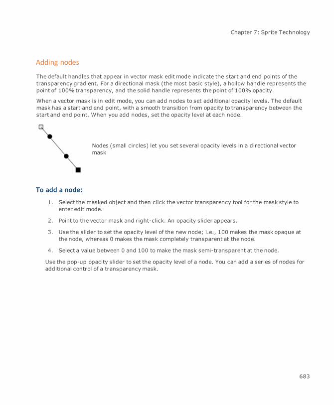
Chapter 7: Sprite Technology
Adding nodes
The default handles that appear in vector mask edit mode indicate the start and end points of thetransparency gradient. For a directional mask (themost basic style), a hollow handle represents thepoint of 100% transparency, and the solid handle represents the point of 100% opacity.
When a vector mask is in edit mode, you can add nodes to set additional opacity levels. The defaultmask has a start and end point, with a smooth transition from opacity to transparency between thestart and end point. When you add nodes, set the opacity level at each node.
Nodes (small circles) let you set several opacity levels in a directional vectormask
To add a node:
1. Select the masked object and then click the vector transparency tool for the mask style toenter edit mode.
2. Point to the vector mask and right-click. An opacity slider appears.
3. Use the slider to set the opacity level of the new node; i.e., 100 makes the mask opaque atthe node, whereas 0 makes themask completely transparent at the node.
4. Select a value between 0 and 100 tomake themask semi-transparent at the node.
Use the pop-up opacity slider to set the opacity level of a node. You can add a series of nodes foradditional control of a transparencymask.
683
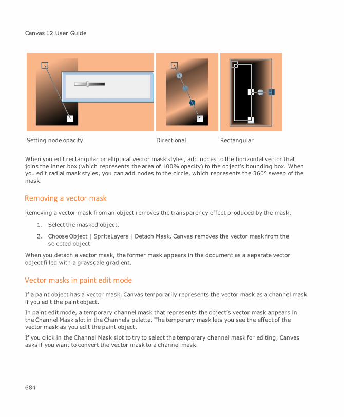
Canvas 12 User Guide
Setting node opacity Directional Rectangular
When you edit rectangular or elliptical vector mask styles, add nodes to the horizontal vector thatjoins the inner box (which represents the area of 100% opacity) to the object’s bounding box. Whenyou edit radial mask styles, you can add nodes to the circle, which represents the 360° sweep of themask.
Removing a vector mask
Removing a vector mask from an object removes the transparency effect produced by the mask.
1. Select the masked object.
2. ChooseObject | SpriteLayers | Detach Mask. Canvas removes the vector mask from theselected object.
When you detach a vector mask, the former mask appears in the document as a separate vectorobject filled with a grayscale gradient.
Vector masks in paint edit mode
If a paint object has a vector mask, Canvas temporarily represents the vector mask as a channel maskif you edit the paint object.
In paint edit mode, a temporary channel mask that represents the object’s vector mask appears inthe Channel Mask slot in the Channels palette. The temporary mask lets you see the effect of thevector mask as you edit the paint object.
If you click in the Channel Mask slot to try to select the temporary channel mask for editing, Canvasasks if you want to convert the vector mask to a channel mask.
684
Chapter 7: Sprite Technology
Click Cancel to return to editing the paint object without destroying the vector mask.
Click Yes if you want Canvas to convert the vector mask to a channel mask that can be editedwith painting tools (see "Editing channel masks" on page 510).
Using transfer modes
All objects—vector objects, text objects, paint objects, and group objects—have transfer modes,which are like invisible filters that affect the appearance of colors. When objects overlap, the transfermode of the front object can change the appearance of the back object.
Transfer modes work with transparency effects, including opacity and transparencymasks;however, transfer modes can make objects appear to be transparent without reduced opacity ortransparencymasks; e.g., Multiply mode lets underlying colors show through an object. The defaulttransfer mode is Normal; i.e., the colors of overlapping objects do not mix unless the front object ispartially transparent.
In addition to interacting with background objects, transfer modes can interact with the document’swhite background. When an object’s transfer mode is Screen, anything white replaces the object’scolor, so the document’s white background can make the object seem to be invisible.
For vector objects, apply transfer modes to fill inks alone or to fill inks and strokes together.
To change an object’s transfer mode:
1. Select an object and choose a mode in the Transfer Mode menu in the Properties bar orTransparency palette.
2. For vector objects, select a Scope option for either the Fill or Fill & Stroke.
Available transfer modes
The following descriptions are based on objects with RGB colors with no other transparency effects.Each mode is described in terms of the front object when the back object’s transfer mode is Normal.
Normal: Colors do not blend; the color of a front object hides the colors of all objects behindit.
Multiply: Overlapping colors become darker. Black produces black. White has no effect, thesame as if a white object were not visible. White text, for example, reveals the background.
Screen: Overlapping colors are lightened. Objects with lighter colors increase the effect.White produces white. Black has no effect, the same as if a black object were not visible.Black text, for example, reveals the background.
685
Canvas 12 User Guide
Overlay: A front object’s color overlays colors in the background, while preservinghighlights and shadows. White and black in the background are not affected.
Soft Light: Underlying colors are lightened or darkened depending on the brightness of thefront color. Colors in front that are lighter than 50% gray lighten the underlying object.Colors in front that are darker than 50% gray darken the underlying object.
Hard Light: Underlying colors are lightened or darkened depending on the brightness valueof the front color. Hard Light mode is similar to Soft Light. However, black in the front objectproduces black; white in the front object produces white.
Darken: The color values of the front color replace the underlying color values if the frontcolor value is darker than the back color value. Black in the background appears unchanged;the front color appears in place of white in the background.
Lighten: The color values of the front color replace the underlying color values if the frontcolor value is lighter than the back color value. White in the background appears unchanged;the front color appears in place of black in the background.
Difference: The color value of the front and back colors are compared and the darker valueis subtracted from the lighter value. If the front and back colors are identical, the result isblack. If the front or back color is black, the other color does not change. If the front or backcolor is white, the other color is inverted.
Dodge: Dodge mode compares the lightness values in each channel of the front and backcolors, and uses the lighter value from each channel for the result color. However, black isnot replaced by a lighter color. White in the front replaces all colors except black.
Burn: Burn mode compares the lightness values in each channel of the front and backcolors, and uses the darker value from each channel for the result color. However, white isnot replaced by a darker color. Black in front replaces all colors except white.
Color modes
Canvas calculates transfer mode effects by applying formulas to color values. Canvas performs thesecalculations using RGB color values or CMYK color values.
For example, the formula for Multiply mode is Color 1 multiplied by Color 2. Canvas applies theformula separately to each value that defines a color. In the case of RGB colors, Canvas applies theformula separately to the red, green, and blue values. For CMYK colors, Canvas calculates the effecton cyan, magenta, yellow, and black values.
The significance of the color space calculation is that the effect you see on screen could appearcompletely different if the effect is printed in a different color space.
686

Chapter 7: Sprite Technology
In particular, you must display transfer mode effects in CMYK if the document will be separated forprinting with process (CMYK) colors. Otherwise, the color separations could produce colors that arecompletely different from the colors you see on screen.
For an example of this effect, draw several overlapping objects with different colors. Set the transfermode of the front object to Difference (see "Available transfer modes" on page 685). Choose Layout |Display Options. In the Display Options manager, change the Mode from RGB to CMYK. Click OK toclose the manager. To refresh the screen, press F5. You will probably see a significant change incolors when you switch fromRGB to CMYK mode.
Select Grayscale from the menu to lessen the required memory if working on complexgraphics or editing images. In Grayscale mode, your screen redraws faster than in CMYK orRGB.
To set the color mode for screen compositing:
1. Choose Layout | Display Options.
2. Select Grayscale, RGB, or CMYK in the Modemenu in the Display Options manager. ChooseRGB for effects that will displayed in RGB colors. Choose CMYK if you are using CMYK colorsin a document that will be printed with process colors.
Transparency and printing
You can use transparency effects to create stunning images and complex illustrations. As with anygraphic effects, however, images that appear perfect on screen can cause problems or produceunexpected results when you print a document. This section discusses some issues you should keepin mind to help ensure that your documents print successfully.
Canvas uses special techniques to print some transparency effects. Canvas can send an instructionto print an opaque rectangle, for example, to most printers; however, to print a transparentrectangle, Canvas usually converts the object to an image. This process is called rasterizing orrendering. Canvas then sends the image data to the printer.
In the Print dialog box, you can select options for printing objects and colors. The options can affectthe time required to print a document, and how well colors match among objects.
Output resolution of transparency effects
You can specify an output resolution for a transparent object. If you don’t specify the resolution,Canvas selects the resolution based on the following guidelines:
687

Canvas 12 User Guide
If a transparent paint object overlaps other paint objects, Canvas rasterizes all the objects atthe same resolution as the paint object that has the highest resolution.
If a vector object is transparent or is behind a transparent object, Canvas rasterizes thevector object at the resolution specified for printing. You can set the resolution for printingin the Output Settings manager in the Configuration Center (see "Setting preferences" onpage 97).
To set the output resolution of an object:
1. Select the object whose resolution you want to specify.
2. ChooseObject | SpriteLayers | Output Resolution to open the Output Resolution dialog box.
3. Do one of the following:
Select the Maximum Resolution check box to specify that the object should be rendered atthemaximum resolution of the output device.
Deselect the Maximum Resolution check box and enter the resolution you want Canvas touse. You can set the resolution from 1 to 2,540 dpi.
4. Click OK.
To set the maximum output resolution:
You can specify a maximum resolution for Canvas output. The resolution you specify in the OutputSettings manager affects output of all objects and rasterizing of transparency effects. This settingoverrides settings you apply to objects with the Output Resolution command (see "Settingpreferences" on page 97).
688

Chapter 8: Multimedia
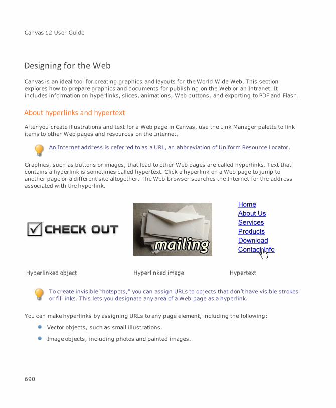
Canvas 12 User Guide
Designing for the Web
Canvas is an ideal tool for creating graphics and layouts for theWorld Wide Web. This sectionexplores how to prepare graphics and documents for publishing on the Web or an Intranet. Itincludes information on hyperlinks, slices, animations, Web buttons, and exporting to PDF and Flash.
About hyperlinks and hypertext
After you create illustrations and text for a Web page in Canvas, use the Link Manager palette to linkitems to other Web pages and resources on the Internet.
An Internet address is referred to as a URL, an abbreviation of Uniform Resource Locator.
Graphics, such as buttons or images, that lead to other Web pages are called hyperlinks. Text thatcontains a hyperlink is sometimes called hypertext. Click a hyperlink on a Web page to jump toanother page or a different site altogether. TheWeb browser searches the Internet for the addressassociated with the hyperlink.
Hyperlinked object Hyperlinked image Hypertext
To create invisible “hotspots,” you can assign URLs to objects that don’t have visible strokesor fill inks. This lets you designate any area of a Web page as a hyperlink.
You can make hyperlinks by assigning URLs to any page element, including the following:
Vector objects, such as small illustrations.
Image objects, including photos and painted images.
690

Chapter 8: Multimedia
Text selections and entire text objects.
Buttons and animations.
To prevent unintended changes, you can’t assign URLs to objects on locked layers, pages,or slides. You must unlock these items prior to making changes.
Using the Link Manager palette
With the Link Manager palette, you can assign hyperlinks to page elements so they jump to files orWeb pages on the Internet, a local hard drive, or an Intranet. In addition, you can create email linksby using themailto: command or define anchors with the Anchor function. You can also add hotspotsto graphics for documents that you intend to export to PDF.
To open the Link Manager palette:
ChooseWindow | Palettes | Link Manager.
691
Canvas 12 User Guide
Link Manager palette
Link Manager menu Open this menu to define an anchor or select an anchor.
Prefixes Click the radio button to select a hyperlink protocol or command from the Linkdrop-down list.
http://www. Hypertext Transfer Protocol. A Web address starts withhttp, followed by the Internet address, path, and name of a Web page;e.g., http://www.acdsystems.com/English/index.htmhttp:// Hypertext Transfer Protocol. A Web address starts with http,followed by the Internet address, path, and name of a Web page;e.g., http://www.acdsystems.com/English/index.htmfile:// File. Let's you link to a file;e.g.,file://C:/Users/<username>/Documents/GettingStartedGuide.pdfftp:// File Transfer Protocol. A file’s URL can start with ftp followed by theInternet address, path, and name of a file;e.g., ftp://ftp.acdamerica.com/public/Guide.pdfmailto: An e-mail link starts withmailto followed by a username, @symbol, and domain name;e.g.,mailto:[email protected]
User defined Click the radio button to select a link from the Link drop-down list.
Pages Click the radio button to select a page or sheet from the Link drop-down list.
[first page]: Jumps to the first page.[last page]: Jumps to the last page.[previous page]: Jumps to the page before the current page.[next page]: Jumps to the following page.[page-top]: Jumps to the top of the current page.[page-bottom]: Jumps to the bottom of the current page.{Page #1}: Jumps to the specified page, sheet, frame, or slide.
Anchors Click the radio button to see select a defined anchor in the current documentfrom the Link drop-down list.
Link Depending on the radio button you selected above, the options available in theLink drop-down list will vary. Select one of the items in the list, enter a URL, orclick the Open File button to select a file, and then click Open.
By default, files that do not have an htm extension do not appear in the
692

Chapter 8: Multimedia
file list. To link toWeb pages, be sure to select files that have the htmextension.
Title Enter a descriptive title for the link. Once published online, when you hoverover the link, the Title appears like a tool tip.
Target Decide how the link will appear in the browser window. The target is the framein which the linked content will open.
Select one of the following:
_top: The linked document loads in the full browser window. All framesare removed._parent: The linked document loads in the parent frame or parentwindow of the frame containing the link. If that frame is not nested, thelinked document loads in the full browser window._self: This is the default target. The linked document loads in the sameframe or window as the link._blank: The linked document opens in a new browser window. Thecurrent browser window is kept available._popup: The linked document loads in a popup window. TheWidth andHeight fields are available with this selection.Relative paths: Create hyperlinks toWeb pages by typing relative paths,rather than complete URLs, in the Link Manager palette. Canvas specifieslinks this way when you select local files by using the Browse function inthe Link Manager palette.
Format text linkswith blue andunderline
Select this check box to format linked text blue and underlined.
When you remove a link, the text remains blue and underlined. It'srecommended that you manually remove this formatting.
Hotspots for PDFExport only
Use the following options for documents that will be exported to PDF.
Select Hotspots: Click to select hotspots in the document.Show/Hide Hotspots: Click to show or hide hotspots in the document.Convert to Hotspot: Click to convert the selected object to a hotspot.Set Hotspot: Click to create a hotspot over the selected object.
693

Canvas 12 User Guide
Apply Click this button to apply the link to the selected element.
Remove Select a link and click this button to delete the link.
Creating hyperlinks and anchors
To assign a hyperlink to an element:
1. In your document, select the element that will contain the hyperlink. You can assignhyperlinks to elements such as text, or vector or image objects.
2. In the Link Manager palette, enter the hyperlink in the Link field, or click the Open File buttonto search for a file.
3. Add a short description in the Title field. This description appears when you hover over thelink when your document is online.
4. Select the appropriate target frame.
5. Click the Apply button to assign the link.
Hyperlinks are case-sensitive; i.e., if a domain or document name uses uppercase, useuppercase and vice-versa in the hyperlink.
You can’t assign a URL or action to objects on layers, pages, or slides that are locked.
To remove an assigned hyperlink:
1. In your document, select the element that has an assigned hyperlink that you want toremove. In the Link Manager palette, the hyperlink appears in the Link field.
2. Click the Remove button.
When you remove a hyperlink from a piece of text, the blue underline formattingremains. You can manually update the text properties to remove this formatting.
To define an anchor:
You can define anchors for various page elements, including text as well as vector and image objects.
1. In your document, select the object to which you want to assign the anchor.
2. In the Link Manager palette, select Define Anchor from the palette menu.
694
Chapter 8: Multimedia
3. In the Anchors dialog box, enter a name for the anchor in the Define a new Anchor field.
4. Click OK to close the dialog box. The defined anchor will appear in the Link drop-down list inthe Link Manager palette when the Anchors radio button is selected.
If you redefine an anchor, make sure you select the Replace existing anchor check box. If itis deselected and you use the name of an existing anchor, a warning dialog box appears.
To create a link to an anchor:
1. In your document, select the element that will contain the link to the anchor.
2. In the Link Manager palette, click the Anchors radio button.
3. In the Link drop-down list, select the anchor.
4. Enter a title and select a Target.
5. Click the Apply button.
To remove an anchor link:
1. In your document, select the element that contains the link to the anchor. In the LinkManager palette, the hyperlink appears in the Link field.
2. Click the Remove button.
To create links between pages:
After you link pages, you will want to export each page as a separate Web page (see "HTML options"on page 715). Using this technique, you can easily convert a single Canvas document into ahyperlinked Web site.
Use the Document Layout palette to assign meaningful names to pages before you createlinks to themusing the Link Manager palette.
1. In your document, select the element that will contain the link.
2. In the Link Manager palette, click the Pages radio button.
3. In the Link drop-down list, select the page to which you want to link.
4. Enter a title and select a Target.
695
Canvas 12 User Guide
With page links, you would generally select _self for the Target since internal linksshould open in the current window.
5. Click the Apply button.
To remove a page link:
1. In your document, select the element that contains the link to a page. In the Link Managerpalette, the hyperlink appears in the Link field.
2. Click the Remove button.
Canvas creates links among pages using file names rather than complete URLs. Therefore,when you create a series of linked Web pages from a Canvas document, be sure to keep theresulting files together in the same folder or directory on the Web server so the links amongthe pages function correctly.
Invalid characters in page names
Since some special characters are invalid in URLs, Canvas converts these characters if they are in apage or slide name that you select in the Link Manager palette.
If invalid characters appear in a page name, Canvas replaces the characters with underscores whenCanvas assigns a URL. Invalid characters include a blank space and the following characters:
Invalid characters in assigned URLs
!
@
#
$
%
^
&
*
(
)
+
=
[
]
{
}
|
tab
`(graveaccent)
~
<
>
?
Testing hyperlinks or commands
If you have attached hyperlinks or mailto commands to objects in your Canvas document, you cantest or follow these links with the Hyperlink pointer.
696

Chapter 8: Multimedia
To test a hyperlink:
1. Select the Hyperlink pointer from the Toolbox.
2. Move the cursor over an object that contains a hyperlink. The cursor changes to a hand.
3. Click the hand on the object and the associated program launches; e.g., Web browser, e-mail program.
About file locations and URLs
In most cases, Web files are created on one computer and transferred to a Web server that isconnected to the Internet. You might create Web pages on your home or office computer, thentransfer the files over a network or the Internet to a Web server.
Web pages often contain links to other Web pages on the same Web server. Because these links arebased on the names and locations of the files on the Web server, changing file names or locations canbreak the links among the pages.
To successfully create hyperlinks among Web pages on your site, you should understand how to userelative directory paths, absolute directory paths, and Internet URL addresses.
Absolute paths: An absolute path specifies a file’s location starting at the top, or root, ofthe directory structure in which the file is stored; e.g., if a file named “Calendar.html” isstored in a folder named Events, inside a folder named Public, which is inside a folder namedHome at the root of the hard drive, the path to the file is:/Home/Public/Events/Calendar.html
Relative paths: A relative path specifies the location of a file relative to the location ofanother file in the same directory structure. Rather than starting at the root of the directorystructure, a relative path starts at the location of one file or folder and lists the relative stepsneeded to get to the specified file. In a relative path, the symbol ../ (two periods and a slash)signifies a move up one step toward the root level in the directory structure.
Complete URLs: Like an absolute path, a complete URL lists the directory path starting atthe root to the location of a Web page on a server. In addition to the path and file name, acomplete URL includes a protocol (http or ftp) and a domain name.
When you create hyperlinks, you can specify the target as a relative path or a complete URL.
If the two pages are in the same folder or directory, the relative path is simply the name ofthe target file.
A complete URL specifies the actual location of the file on a Web server on the Internet.
697
Canvas 12 User Guide
You can enter a relative path or a complete URL in the Link field. When you use the Browse button inthe Link Manager palette, Canvas can enter a relative path or a complete URL.
Creating PDF hotspots
In Canvas you can create hotspot links for selected areas of a graphic. For example, if you wanted touse a graphic for navigation between the pages, you could add hotspots to the graphic so that userscan jump from page to page in the PDF.
By default hotspots are not printed when you print a Canvas document, but you can choose to printthem if you need to. To set a hotspot to printable or to delete a hotspot, you must unlock the hotspotobject first.
PDF documents only support rectangular hotspots, so when you export a Canvas documentto PDF, all hotspots become rectangle objects.
To create a hotspot:
1. In your document, do one of the following:
Select an object in the graphic.
Draw a rectangle over the area you want to set as a hotspot.
2. In the Link Manager palette, click one of the following:
Set Hotspot: Creates a new hotspot object over top of the existing object.
Convert to Hotspot: Replaces the existing object with a hotspot object.
3. Enter the Link, Title, and Target.
4. Click Apply.
You might choose to create a separate layer for hotspot objects as a way of organizingthem.
To remove a hotspot link:
1. Select the hotspot object.
2. In the Link Manager palette, click Remove.
698
Chapter 8: Multimedia
The hotspot link is deleted, but the hotspot object remains so that you can enter a newhotspot link.
To delete a hotspot:
1. Select the hotspot object.
2. ChooseObject | Unlock.
3. Press the Delete key.
The hotspot object and link are deleted.
To print hotspots:
1. Select the hotspots you want to print.
2. ChooseObject | Unlock.
3. ChooseWindow | Palettes | Document Layout.
4. In the Document Layout palette, set the hotspot objects to Printable. See "Using theDocument Layout palette" on page 85.
Pixel mode
The Pixel Mode setting allows users to view graphics at 72 ppi before they are rendered. At the sametime, all of your graphics will remain fully editable. Pixel Mode also prevents pixel shifting, whichsometimes occurs when objects are exported to theWeb.
To turn on pixel mode:
See "Display options" on page 101.
Creating slices
Professional Web designers will confirm that a fast download time versus a slow one can spell thedifference between commercial success and failure. A visitor may quickly loose patience and hit thedreaded Back button if forced to wait too long for a Web page to load. Slicing large images into small,faster-loading pieces is one of theWeb design tricks most often used.
A slice is a rectangular area of an image that becomes a cell in an HTML table. The HTML table is thenexported to be placed onto a Web page.
You can import the table into an HTML editor for further editing.
699
Canvas 12 User Guide
We suggest that you preview your work in a browser to ensure that your document will appearcorrectly. Also, remember that an image may appear differently when it is viewed on other platforms.
Slice Creator
Slice Selector
The tools that you need to use are the Slice Creator and the Slice Selector. The creation andmanipulation of slices can only be accomplished when either of these two tools are activated.
The slicing tools lets you optimize and export any Canvas object for use on theWeb. In addition, youcan assign a URL to a specific slice (see "About hyperlinks and hypertext" on page 690).
If you are new to slicing, then you need to know that Canvas contains default settings that allow youto quickly perform the slicing function. In other words, you may immediately begin slicing an imageand Canvas will assign default settings; however, so that you can achieve the optimal results, wesuggest that you review Slicer Preferences (see "Slicer preferences" on page 700).
By using the Slicer Preferences prior to exporting an HTML table, you can efficiently manage yourslices and significantly reduce the likelihood of potential problems. The procedure for properlysetting up the export of your slices into an HTML table is detailed later in this section.
Slicer preferences
Double-click the Slice Creator icon or Slice Selector icon to open the Slicer Preferences in theConfiguration Center.
General options Name template: Assign a name to the slice template. This default nameis shared by all of the slices. The name specified here must always useone of the formatting marks (either “# ” for numbers or “&” for a letter).If these marks aren’t used, then the application automatically adds a (#)to the end of the name. Other formatting keywords, such as [document]and [page] or a combination of these keywords, could be used togetherwith the formatting marks. Additional naming information will beprovided later in this section. A default name is automatically applied to atemplate if you don’t enter one; however, if a Web page is going to havemore than one HTML table (which will contain a sliced image), then it’s agood idea to assign a unique template name before exporting the slices.
Split preference: Choose a way of splitting overlapped slices. Bydefault, slices are split without any preference. In that case, Canvasautomatically designates where or how to split an overlapping slice.
You may edit the default by selecting either vertical or horizontal as your
700
Chapter 8: Multimedia
choice. The Splitting preference remains in effect for all overlappingslices.
Changing this preference affects all existing (overlapping)slices, but not those that are hard-split using the Splitcommand.
Default imageoptions
Image format:
Automatic: Canvas chooses the file format for images (see "Howimages are handled" on page 718).JPEG or GIF: Select either option to save all images in one formator the other.
JPEG Quality:
Best: least compression (100% quality).Fine: 90% quality.Good: 75% quality.Draft: most compression (50%quality).
Anti-aliasing: Smoothes the edges of rendered vector objects and textobjects.
Finest: Uses up to 256 shades between each pair of colors.Images with more than 256 colors should be saved in JPEG formatto preserve the full range of shades. If necessary, Canvas usesJPEG format if you select the Automatic Image Format option.Fine: Uses 64 shades per pair of colors. Medium uses 16 shadesper color pair. Coarse uses four shades per color pair.None: No anti-aliasing.
Select Save these settings as the default to make these settings yourdefault slicer preferences.
701
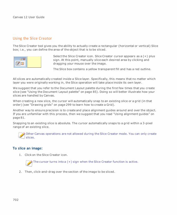
Canvas 12 User Guide
Using the Slice Creator
The Slice Creator tool gives you the ability to actually create a rectangular (horizontal or vertical) Slicebox; i.e., you can define the area of the object that is to be sliced.
Select the Slice Creator icon. Slice Creator cursor appears as a (+) plussign. At this point, manually slice each desired area by clicking anddragging your mouse over the image.
The Slice box contains a yellow transparent fill and has a red outline.
All slices are automatically created inside a Slice layer. Specifically, this means that no matter whichlayer you were originally working in, the Slice operation will take place inside its own layer.
We suggest that you refer to the Document Layout palette during the first few times that you createslice (see "Using the Document Layout palette" on page 85). Doing so will better illustrate how yourslices are handled by Canvas.
When creating a new slice, the cursor will automatically snap to an existing slice or a grid (in thatorder) (see "Drawing grids" on page 299 to learn how to create a Grid).
Another way to ensure precision is to create and place alignment guides around and over the object.If you are unfamiliar with this process, then we suggest that you read "Using alignment guides" onpage 81.
Snapping to an existing slice is absolute. The cursor automatically snaps to a grid within a 3-pixelrange of an existing slice.
Other Canvas operations are not allowed during the Slice Creator mode. You can only createslices.
To slice an image:
1. Click on the Slice Creator icon.
The cursor turns into a (+) sign when the Slice Creator function is active.
2. Then, click-and-drag over the section of the image to be sliced.
702

Chapter 8: Multimedia
Each yellow-shaded box represents a sliced area.
Using the Slice Selector
Once you have sliced the image, you may need to edit and move it. To do this, select the Slice Selectortool.
The Slice Selector tool allows you to select, move, resize, copy, or delete the slice. You also have theoption to both Undo and Redo any of the previously mentioned procedures.
Slices can’t be rotated or skewed. Additional slice-related commands are available through acontext menu (see "Slice operations context menu" on page 706).
To view slice properties:
1. Select the slice with the Slice Selector tool.
2. Right-click to open the context menu.
3. Select Properties to open the dialog box.
703
Canvas 12 User Guide
Certain slice properties are available in the Properties bar when a slice is selected.
Slice properties
Change slice’s indexto
Change the index of any selected slice. This function could be necessaryif the index is part of the slice’s name when using either the ‘#’ or ‘&’formatting symbol. It is available only if one slice has been selected.
First select the Change slices index to box. Enter either a number orchoose one of the existing indices available in themenu.
Naming Slice name: Enter the name of the slice or choose one of the valuesfrom the menu. [current] indicates that the name won’t be changed.[default] means the default name is used. [document] is the currentdocument’s name. This keyword can be combined with the [page]keyword and with (&) or (#) formatting marks or with other text. Nameslike [document]_[page]_slice_## are legal and may be used. [page]represents the current page name. This keyword can be combined withthe [document] keyword and with (&) or (#) formatting marks.
# denotes the index of the slice. By using this setting, the indexwill beformatted as a number. More than one of these marks may be used; e.g.,if you type “Image_###” and the index of the image is 7, then the nameof the image would be “Image_007.” Otherwise, if only onemark is used,then the namewould be “Image_7.” This mark (or a set of them) can beused only once in the name and it is mutually exclusive when using the(&) as a formatting mark.
& represents the index of the slice, but it is formatted as a letter. Morethan one of these marks may be used to format a text designation thatcontains more than one letter; e.g., if you type “Image_&&&” and theindex of the image is 7, then the name of the image is “Image_aag.”Otherwise, if only one mark is used, then the namewould be “Image_g.”This mark (or a set of them) can be used only once in the name and it ismutually exclusive when using the (#) as a formatting mark.
If more than one slice is selected, then a name with either (#) or(&) formatting mark is required since each slice must have aunique name.
Use ASCII characters only and ensure that the name doesn’t contain aspace between the characters.
704

Chapter 8: Multimedia
Alt text: assigned alternative text won’t take effect until it is exported toHTML. Some browsers display alternative text by default while the imageis being downloaded. Alt text may have up to 64 characters and does nothave to be in ASCII format.
Image title: A title will take effect only if it is exported to HTML. Bydefault, a browser will display the title as either a tool tip or on the statusbar when you move the cursor above the image. The image title messagemay contain up to 64 characters. These characters do not necessarilyneed to be in ASCII format.
Image Options Setting mode
Default options: The slice(s) will share the Slicer’s default setting.
Optimized: When checked, the standard dialog for image optimizationwill show up. You can set any combination of image parameters. Afteryou close the dialog, a summary of the settings will be displayed alongwith a small button. Clicking the button will reopen the optimizingdialog. For more information on how to optimize an image’s parameters,see "Saving Web graphics (GIF/JPEG)" on page 143.
Although it is possible to select a transparent color (or colors)when optimizing GIFs, such settings will be lost after returningto the Slice Preferences dialog.
Simple setting: Using this mode, you can choose the desired optionsfor anti-aliasing, image format, and JPEG output quality.
Anti-aliasing, Image format and JPEG quality image options are the sameas the ones that appear in "HTML options" on page 715.
705

Canvas 12 User Guide
Slice operations context menu
The context menu can only be accessed if the Slice Selector tool is selected. Some of the commandsare available only if they are relevant to the context of the current situation.
To open the slice operations context menu:
Right-click the Slice Selector tool on a slice.
Select this slice: selects the slice at the cursor’s current position.
Deselect this slice: Deselects a slice if it is the only one selected.
Remove from selection: Removes the slice at the cursor position from the selection set.
Select/Deselect all slices: Selects or deselects all slice objects.
Delete slice(s): Deletes all currently selected slices.
Divide slice: Allows you to divide a slice horizontally and/or vertically into smaller slices.When choosing this command, the Slice divider dialog box appears with two options.
Slice Divider dialog box
Horizontally Specifies how many horizontal portions in which the slice will be divided.To prevent horizontal division of the slice, a value of 1 can be specified.
Vertically Specifies how many vertical portions in which the slice will be divided.To prevent vertical division of the slice, a value of 1 can be specified.
Using this method, a slice that overlaps another slice cannot bedivided.
Split slice: Splits all selected slices that are overlapped by other slices. Slices are slicedalong the soft slice-lines. This operation separates the image into individual slices. Theseslices will have the parent slice’s parameters by default, but the parameters can be modified.
Export slice: Exports slices as images. It can also create an HTML file with a table that willcontain all of your image slices (see "Exporting slices" on page 707).
706

Chapter 8: Multimedia
Arrangement commands: Will arrange selected slices in a certain order: Shuffle Up,Shuffle Down, Bring to Front, Bring to Back (see "Arranging objects in the stacking order" onpage 180).
Exporting slices
Once you have finished slicing your work, you can export the images (GIFs or JPEGs). You can alsocreate an HTML file with a table that contains all of the images. The options to perform thesefunctions are available in the Slicer Export Options dialog box.
Slicer Export options
To open this dialog box, select Export Slices from the Slice Operations menu.
Replace existingimages
Selecting this item automatically replaces existing images that have thesame file name and location. If deselected, a dialog box will warn youwhen a slice is about to be replaced.
HTML Export options Creates an HTML file that will contain the images to be exported. The filewill contain one table that will link with all of the images. These settingscan affect how the HTML table will be designed.
Render empty slices If checked, all empty spaces (within the rectangle that determines theboundary of all of the selected slices) will be rendered. If not checked,the cell in the tablewill appear to be empty. For rendering the emptyslices, default image options will be used.
Use spacing GIFs When working with complex tables, it may be necessary to use a one-pixel wide transparent GIF image as a spacer. These spacers force aWeb browser to accurately display a complex HTML table. Choose apredefined name or enter your own spacer name with only HTML-safecharacters.
Images to subfolder Allows you to name a subfolder to which all images will be exported. Ifnot checked, then images will be created in the same folder where theHTML file is being exported. The name of the subfolder should containHTML-safe characters only.
Text encoding If activated, all text (i.e., alternative texts and image titles) will beencoded using the specified encoding. Also, the information about whichencoding is used will be declared in the HTML file’s header. Western(ISO) is best used for the western Latin alphabet. Unicode (UTF-8) isbest used for other alphabets (central European, Cyrillic, Asian) ormixed alphabets.
If no encoding is required, then all of the text is exported as is. Only
707

Canvas 12 User Guide
invalid characters are encoded so that the HTML output will always bevalid.
Force default imageoptions
If this option is turned on, then the individual image parameters will beoverwritten by the Slicer’s default options. This image setting istemporary and will not affect parameters of individual slices.
See "HTML options" on page 715 for the image options, which are Imageformat, JPEG quality, and Anti-aliasing.
Assigning URLs to slices
Selected individual slices or groups of slices can be assigned a URL by using the Link Managerpalette. Choose Object | Options | Link Manager to open the palette. The process is the same asassigning a URL to an ordinary object; however, the slice or slices must be selected with the SliceSelector (see "Using the Link Manager palette" on page 691).
Using Web buttons
If you plan to export your Canvas document to theWeb, you may want to add some interactiveelements such as Dynamic Web buttons. Web buttons can lead visitors to another page within a siteor link to a different URL altogether.
TheWeb Button tool opens theWeb Buttons palette and places buttons in documents.
Understanding the button states
These buttons are called dynamic because they change their behavior, or state, according to theuser’s actions. Dynamic Web buttons have a total of 3 states:
State Explanation Example
Up This is the default, or normal, state of the button. Themouse isnot over the button area.
Over This is the state when themouse is moved over the button area.
Down This is the state when themouse clicks the button area.
708

Chapter 8: Multimedia
When you create a button, you can use a separate object or image for each of the button’s states.
Dynamic Web buttons may also be referred to as rollovers.
All vector or text objects to be used as Web buttons must have a pen ink and fill ink. Objectsthat have the pen and fill inks set to “none” can’t be dragged into theWeb Buttons palette.
Web Buttons palette
Double-click the Web Button tool to open theWeb Buttons palette.
Button state boxes Drag the images, text objects, or vector objects into each state’srespective box.
Remember that the Up state is the default state.
Preview box If you’ve defined all 3 states, you’ll see the Over state when themousepasses over the box. Click the mouse on the box to see the Down state.
Storage box Drag the defined button from the Preview box to this box (see "To store aWeb button:" on page 709).
Web Buttons palettemenu
Open this menu to load, append, save, or clear buttons (see "Saving andclearing Web buttons" on page 711 and "Loading and appending Webbuttons" on page 711).
To create a Web button:
You can drag objects into the boxes in any order.
1. Drag the object for the Up state into the Up box.
2. Drag the object for the Over state into the Over box.
3. Drag the object for the Down state into the Down box.
To store a Web button:
Drag the completed button from the Preview box to the Storage box.
To delete a Web button:
Drag the button you want to delete to the trash can icon in the palette.
709
Canvas 12 User Guide
To modify a Web button’s state:
Drag the object from the Up, Over, or Down box into the document. Modify the object and drag itback into its respective box. Store the updated button and place a copy in your document.
You can’t edit a button’s attributes, such as pen ink, fill ink, and stroke.
To test Web buttons:
Before storing a new button, test it in theWeb Buttons palette (see "Web Buttons palette" on page709). As indicated previously, the Up state is the default state (see "Understanding the buttonstates" on page 708). Move the cursor over the Preview box to see the Over state and then click tosee the Down state.
If you’ve already placed theWeb button but want to see their appearance before exporting to HTML,use the Play feature on theWeb Buttons palette.
Don’t work in Canvas while play mode is active. Click End Play Mode before starting otherwork.
Click the Start Play Mode button and the placed Web buttons go into playmode. Move the cursor overthe buttons and click them to see the 3 states. When you finish, click End Play Mode.
To place Web buttons in a document:
Use this procedure to place Web buttons in a Canvas document.
If you want to placemultiple copies of the same button, use this procedure once, and thensee "To place additional Web buttons:" on page 711.
1. In the Storage box, select the button that you want to place. The selected button appears inthe Preview box.
2. Move the cursor into the document area. The cursor changes to a placement icon.
3. Do one of the following to place the button:
Click to place the button.
To scale the button, drag to create a bounding rectangle.
When the Web Buttons palette is closed, you can use the Web Button tool to place the lastselected button.
710
Chapter 8: Multimedia
To place additional Web buttons:
To place copies of the same button, use theWeb button tool again or select the first button andchoose Edit | Duplicate to create duplicates.
To resize Web buttons:
Select the placed Web button and drag a handle to resize its bounding rectangle.
To attach a URL to a Web button:
Use the Link Manager palette to link buttons to other HTML files or URLs (see "Using the LinkManager palette" on page 691).
Saving and clearing Web buttons
When you save a Web button in the palette, it’s available in all Canvas documents.
Save the Web buttons on the network so your co-workers can use them as well.
To save buttons:
1. In the palette’s menu, chooseSave Buttons.
2. Select a directory in which to save the file.
3. Enter a name for the file and click Save.
To remove all buttons from the Web Buttons palette:
ChooseClear Buttons from the palette’s pop-up menu.
Loading and appending Web buttons
When you load a Web button file, the buttons currently in the palette are replaced by the button file.If you don’t want to lose the current buttons, you should save the current buttons in a button file (see"To save buttons:" on page 711).
When you append a button file, the current buttons are not replaced. Instead, the buttons in the fileare added to the end of the palette.
To replace all buttons in the palette with those in a button file:
Choose Load Buttons in themenu. Select a button file and click Open.
711
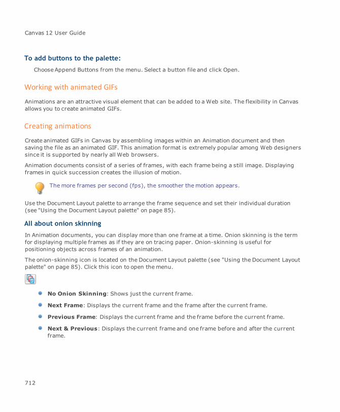
Canvas 12 User Guide
To add buttons to the palette:
ChooseAppend Buttons from the menu. Select a button file and click Open.
Working with animated GIFs
Animations are an attractive visual element that can be added to a Web site. The flexibility in Canvasallows you to create animated GIFs.
Creating animations
Create animated GIFs in Canvas by assembling images within an Animation document and thensaving the file as an animated GIF. This animation format is extremely popular among Web designerssince it is supported by nearly all Web browsers.
Animation documents consist of a series of frames, with each frame being a still image. Displayingframes in quick succession creates the illusion of motion.
Themore frames per second (fps), the smoother themotion appears.
Use the Document Layout palette to arrange the frame sequence and set their individual duration(see "Using the Document Layout palette" on page 85).
All about onion skinning
In Animation documents, you can display more than one frame at a time. Onion skinning is the termfor displaying multiple frames as if they are on tracing paper. Onion-skinning is useful forpositioning objects across frames of an animation.
The onion-skinning icon is located on the Document Layout palette (see "Using the Document Layoutpalette" on page 85). Click this icon to open themenu.
No Onion Skinning: Shows just the current frame.
Next Frame: Displays the current frame and the frame after the current frame.
Previous Frame: Displays the current frame and the frame before the current frame.
Next & Previous: Displays the current frame and one frame before and after the currentframe.
712
Chapter 8: Multimedia
Custom: Choose this option to display any number of frames adjacent to the current frame.Enter the number of frames to display.
When onion-skinning is active, names of the displayed frames are tinted in the layout list.
Exporting an animated GIF
Once you’ve created your animation, it is time to export it as an animated GIF.
You should save your file first in Canvas format (.CVX).
To save as animated GIF:
1. Choose File | Save As.
2. Select GIF Animated as the file type.
3. Enter a name for the file.
4. Click Save.
5. In the Animated GIF Options dialog box, select the animated GIF options.
Animated GIF options
TransparentBackground
Makes the background transparent.
Auto Crop Optimizes the size of each frame and the document. The Auto Cropfeature will create the minimum size needed to accommodate all of theobjects in the document.
Interlaced The image will load into a browser a little bit at a time. Activating thisfeature creates the effect of improving an image over a slow connection.
Anti-aliasing Objects from the Canvas document will be rendered with an overallsoftened effect.
Individual PalettePer Frame
If selected, each GIF frame will contain its own palette. This will create alarger GIF image; however, this setting is suggested if you are creatingcomplex and colorful animations. If this option is not checked, then allframes will have a common palette. The color palette maximum is 256colors.
Erase Previous Frame Each frame will be erased and the area will be restored to thebackground before the next frame is displayed during playback.
713

Canvas 12 User Guide
Optimize frames This feature minimizes the size of a file that will be created. Werecommend this setting if you are working with colorful GIFs or pictures.The Optimize frame setting has no effect on simple graphics, likerectangles, ovals etc.
Differential frames This option searches for the smallest frame possible in the set thatcontains all of the changes from a previous frame. After the search, itcreates a new rectangle which becomes the new frame.
If the Erase Previous Frame option is checked, then thisparticular option will be unavailable. For more information onusing animated GIF options, see "Working with animated GIFs"on page 712.
Infinite Loop Activating this option will cause your animation to run (loop)continuously.
You may specify the number of times that your animation willrun. To do this, simply enter the number of times to “loop” youranimation in the Times box.
Creating Web pages from Canvas documents
Any document that you create in Canvas can be exported for the Web in a matter of seconds. Toexport a document as one or more Web pages, save the document in HTML format.
Canvas does not support opening and editing of HTML Web pages; therefore, always save yourdocuments in Canvas format (.CVX) before you exportWeb pages. Saving in Canvas format meansyou can edit the original and export again in HTML.
To save a document in HTML format:
1. Open the Canvas document that you want to save as one or more Web pages, and thenchoose File | Save As.
2. In the directory dialog box, select HTML file format.
3. Select a location to save the files, enter a file name, and click Save.
714

Chapter 8: Multimedia
4. In the HTML Options dialog box, select options for saving the Web pages (see "HTML options"on page 715).
5. Click OK to save them.
HTML options
General options Create new folder: Organizes files for a Web page by placing them ina new folder in the specified location. The name that you enter whenyou are saving a Web page is used for the folder’s name.
Put images in subfolder: Creates a subfolder for the image files.
Separate pages: Available for multi-page Canvas documents; createsa Web page from each page. Page names will become the file names. Ifyou do not select this option, then Canvas exports all pages as oneHTML file.
Generate navigation file: If you select Separate pages, you may wishto activate this option; generates navigation aids placed on the top andleft side of each Web page. These links are created from the index nameof each Web page.
Use external style: Select this option to create an external style sheetfor Web pages that you are saving. An external style sheet can make iteasier to edit styles manually and can also reduce the size of individualHTML files because the complete style information is not included ineach Web page file.
Not available if Table Layout is active since Table Layout doesn’tuse global CSS definition.
File format: Two types available: HTML 4 and XHTML 1, with only afew differences between them. XHTML documents differ in thedocument’s header and have some additional tags in the data stream(such as end-tags for image objects).
Layout mode: Three modes are available for both file formats.
Table Layout: Allows all Canvas objects to be organized into cellsof an HTML table. All overlapping objects are rendered andexported as bitmaps. Although tablemode may produce lessefficient HTML output, it is accepted by all major browsers.
715
Canvas 12 User Guide
CSS2 (Cascading Style Sheet): Graphics and text objects willbe positioned using the “absolute position” property (defined bythe CSS2 specification). In this mode, objects can overlap eachother without the need for you to render them. Some browsershave problems dealing with CSS2 format. Only Internet Explorer4.x + (as well as AOL 4+) and Netscape Navigator 6.x can supportCSS2 layout without problems.
CSS properties are also used in the Table Layout but only fortext formatting not for positioning.
Table Layout Centered: HTML output is the same as thestandard “Table Layout”; however, table is centered in a browser.
716
Chapter 8: Multimedia
Text options Render Text: Rendering converts text objects to images to ensure thattext appears the same on theWeb. Rendered text can’t be selected astext on a Web page.
Automatically: Canvas decides when to render text.AlwaysNever: Preserve all text as text objects.
Image options Image format:
Automatic: Canvas chooses the file format for images (see "Howimages are handled" on page 718).JPEG or GIF: Select either option to save all images in one formator the other.
JPEG quality: Four JPEG quality levels are available:
Best: Least compression (100% quality).Fine: 90% quality.Good: 75% quality.Draft: Most compression (50%quality).
Anti-aliasing: Smoothes the edges of rendered vector objects and textobjects.
Finest: Uses up to 256 shades between each pair of colors.Images with more than 256 colors should be saved in JPEG formatto preserve the full range of shades. If necessary, Canvas usesJPEG format if you select the Automatic Image Format option.Fine: Uses 64 shades per pair of colors. Medium uses 16 shadesper color pair. Coarse uses four shades per color pair.MediumCoarseNone: No anti-aliasing.
Select Save this setting as default to save the current settings in thedialog box for all documents. Otherwise, Canvas saves the settings forthe current document only.
Save these settingsas default
If you have never selected the save settings option, clicking Default willswitch the dialog box settings to the Canvas default.
717
Canvas 12 User Guide
Metatags
When Canvas creates an HTML file from a document, it uses metatags in the HTML file header toinclude data entered in the document Properties dialog box. This data includes information such asTitle, Subject Keywords, Author, and Category from the fields on the Summary tab in the DocumentProperties dialog box.
To add metatags to a document:
Choose File | Properties and click the Summary tab. Enter any keywords in the fields.
How images are handled
Canvas uses compression and color reduction to optimize images for faster display on Web pages. Allgraphic objects are exported as RGB images in GIF or JPEG format. You can choose the image formator allow Canvas to decide this option for you (see "Image options" on page 717).
When you select Automatic from the Image format menu, Canvas exports RGB Color and CMYKColorimages as RGB (24-bit) images using JPEG compression. Indexed mode images, which use amaximum of 8 bits of color information per pixel, are exported in GIF format. Black and White imagesare exported as Indexed images (8-bit). Canvas exports Grayscale images as Indexed images (8-bit)or JPEG-compressed RGB images, using the format that it determines will produce the best results.
How slices are exported
If slices are available in the Canvas document at the time of HTML export, then Canvas will design thedocument layout to conform to the slices. Canvas will also accept an individual slice’s setting when itrenders and names the images (see "Exporting slices" on page 707 and "Slicer Export options" onpage 707).
Slices are used only when Table Layout is activated.
How animated GIFs and Web buttons are handled
When exporting animated GIFs, one GIF file will be produced for each animated GIF.
Regarding Web buttons, one image for each Web button’s state will be exported. This group ofimages will be linked together using Java scripting.
You cannot overlap these objects in Table Layout mode. If that happens, then an Animated GIF orWeb button will be rendered and exported as a simple image. You can overlap the objects in CSSLayoutmode only.
718
Chapter 8: Multimedia
EXIF extension (JPEG)
EXIF is the abbreviation for Exchangeable Image File, a format that is a standard for storinginterchange information in digital images using JPEG compression. Almost all new digital camerasuse the EXIF annotation, storing information on the image such as shutter speed, exposurecompensation, F number, what metering systemwas used, if a flash was used, ISO number, dateand time the image was taken, whitebalance, auxiliary lenses that were used, and resolution.
Canvas allows digital photographers quick and easy access to most of the information that is attachedto these images. After being imported into Canvas, the attached data may be viewed by choosingImage | DCS information (EXIF). This command is disabled if the image does not contain EXIF data.
You can also view the EXIF data via a context menu. Select the image and right-click to open themenu. This command will not appear if the JPEG file does not contain EXIF data.
An option to include or remove EXIF data when exporting JPEG images has also beenincluded in the Export Preview.
The EXIF option is available from the Export Preview window. If an image does not contain EXIF data,then the option is grayed out as shown in this example.
Using the Save to Web command
The easiest way to create Web pages in Canvas is to save a Canvas document using the Save to Webcommand.
Prior to exporting your document as an HTML file, we recommend that you make certain tosave your original project as a Canvas file. You can then edit the original Canvas document ifyou want tomake changes at a later date.
To save a Web site using Save to Web:
1. Choose File | Save ToWeb to open the Save to Web dialog box, which contains controls forrange, as well as image and html export.
2. Select the export range by enabling an option in the What to save section.
3. Select either Auto, GIF, or JPEG for the image export in the Format for saving images section.
4. Open the HTML output method menu and select either HTML 4 with Table Layout or CSS2Layout.
719
Canvas 12 User Guide
5. Select an anti-aliasing method to smooth the edges of objects that Canvas renders for export.Coarse uses the least number of colors and Finest uses themost.
Exporting as a Flash file
Canvas provides compatibility for designing Web content to be used in a Flash®-enabled Web site.As a result, all Canvas documents can be saved in the .SWF format.
To save a Flash file:
1. After completing your document, choose File | Save As.
2. In the Save As dialog box, select the Macromedia Flash (.SWF) option. Click the Save button.
Flash Options dialog box
General options Export mode: Choose between SWF Player or SWF Editor.
SWF Player: Creates an .SWF file for use in Macromedia Flashplayer or a Flash-enabled Web browser.SWF Editor: Generates the .SWF file for import intoMacromediaFlash.
Exporting an .SWF file for use in an .SWF player doesn’tautomaticallymean that the file can’t be imported into a .SWFeditor or vise-versa. However, to reduce possible problems, wesuggest that you export your Canvas file using a mode thatmatches your specific Flash export needs.
Page export: This feature allows you to have the option to save amultipage document either as a single multiframe .SWF file or as a set ofindividual .SWF files:
Individual files: Allows a multi-page Canvas document to beexported as separated SWF files. One will be created for each pagein a Canvas document.File with frames: Enables a multi-page Canvas document to beexported as a single multiframe .SWF file.
Accurate strokes (slower): Enables exporting graphics that containeither calligraphic strokes or strokes that use texture, gradient, or hatchpatterns.
720
Chapter 8: Multimedia
This option may make the export process slower.
Image options This feature allows you to choose an image format that will be applied tothe original Canvas file when exported as an .SWF file.
Image format:
JPEG: Produces well compressed images. Loss of datamay have animpact on image quality.LossLess: Does not affect the quality, but the compression ratio isusually lower than using .JPEG.
JPEG quality: This option is only available if the lossy (JPEG)compression has been selected. Four JPEG quality levels are available:
Best: 100% of quality is preservedFine: 90% of quality is preservedGood: 75% of quality is preservedDraft: 50% of quality is preserved
Best should be chosen if a detailed image is desired and file size is not aconcern. Draft can be selected if you need a small file for transmissionand image quality is not an issue. Usually the Fine quality optionprovides the optimal quality-to-size ratio.
721
Canvas 12 User Guide
Save these settingsas default
Select this option if you wish to save these settings as the default for allsubsequent SWF files.
Exporting as PDF
You can export Canvas documents to the Portable Document File (PDF) format. Canvas has the abilityto apply security settings and embed fonts, and halftone settings. A specific color mode is alsoavailable so that it may be applied to all PDF objects. Also, the whole file can be compressed by thePDF export filter.
To export to PDF:
1. Choose File | Save As.
2. Select PDF - Acrobat™ files as the format.
3. Enter a name for the file and click Save.
4. In the PDF Options dialog box, select the PDF options.
PDF Options dialog box
General options Compress text and vectors: All vector graphics, including a streamoftext data, is compressed when this option is activated.
Apply 7-bit ASCII encoding: If activated, all binary data is filteredthrough an ASCII filter, which converts a file so it can pass through adata channel that supports 7-bit data only (e.g., e-mail servers). ASCIIencoding increases data size to an approximate ratio of 5 to 4.
Add security features: Select this check box and the Security Optionsdialog box opens. To adjust security settings, click the Settings button(see "Security settings" on page 724).
Exact character positioning: Each character of a text object ispositioned individually to achieve maximal precision. This choiceproduces a little larger PDF file; however, if precise text layout isrequired, this option is correct. If this option is deselected, the PDFexport filter tries to merge together as many characters as possible toformwhole words and lines of text. This way, it is easier to work withtext if the user decides tomodify the PDF file later when imported back inCanvas.
722
Chapter 8: Multimedia
Embed font subsets: Select this option to embed subsets of allTrueType and PostScript (Type1) fonts. Click the Settings button to viewthe various font embedding options (see "Embedding font subsets" onpage 724).
Current page only: Select this option to export the current page.
Create PDF layers: Select this option to export the document layers inthe PDF. If not selected, all objects export on one layer. If a layer ishidden, that layer will not export.
Export non-printable objects: Select this option to export objects thatare not printable in the Document Layout palette (see "Setting options inthe palette" on page 86).
Convert all colors to: If activated, the color of all vector, text, andimage objects is converted to RGB or CMYK. If not selected, all objectsretain their original color mode.
Images Resolution: Affects bitmap rendering. Default settings are 72 or 96dpi. The chosen resolution is applied to all images. We recommend 72 or96 dpi for online documents. A printed document requires 150 or 300dpi. You may choose a higher value; however, 300+ dpi produces alarge file size.
Compression: Bitmaps are compressed during export. Choose lossless(ZIP) or lossy (JPEG) compression. Lossless is appropriate for technicaldrawings, illustrations, or cartoons, while JPEG compression is best forphotographs.
JPEG quality: Only active if lossy (JPEG) compression has beenselected. Four quality levels are available: Best, Fine, Good, and Draft.These options are the same as the ones for Flash Export (see "FlashOptions dialog box" on page 720).
723
Canvas 12 User Guide
Transparency Use the Render and Color mode options to decide how colors of atransparent object are rendered (see "Transparency settings" on page725).
Specify halftonesettings
Select halftone information to store inside the PDF. If no settingsspecified, custom halftone information isn’t applied to a document. Thehalftone setting of the output device isn’t used when printing your PDF(see "Halftone settings" on page 725).
Save these settingsas default
If selected, the settings will be the default PDF settings.
Click the Default button to restore the default settings file.
Security settings
When exporting to PDF, you can set one password for opening the document and an additionalpassword for permissions and restrictions for various features such as printing and copying. Thesepasswords are independent of each other.
If you want to define a password to open the document, select the Require password to opendocument check box and define the password.
Anyonewho needs to open the PDF must have this password.
If you want to establish permissions for various options, select the other check box and define theother password. Then select the check boxes for the options that the user is able to perform; i.e.,printing, copying, extracting.
If an option is not selected, the user cannot perform this action.
Embedding font subsets
The creation of subsets means that only characters used in the document are embedded.
This setting ensures the safe electronic transfer of a document between different platforms,machines, or offices; however, embedding the fonts could dramatically increase the size of theresulting PDF document.
To view the other options, click the Settings button to open the Font embedding options dialog box.
724
Chapter 8: Multimedia
Embed all fonts: Select this option to embed all fonts.
Embed all fonts except standard PS fonts: Select this option to embed only the fontsthat are not standard postscript fonts.
Embed all fonts except these: Select this option if you want exclude specific fonts frombeing embedded.
Embed none but these fonts: Select this option to specify which fonts should beembedded.
For the last two options, click the Add fonts button if you don’t find the font in the list. In the Availablefonts dialog box, select the fonts that you want to add to the list.
Transparency settings
These settings decide how colors of a transparent object are rendered.
Render mode
Specify which area of a transparent object is rendered.
Smallest area: Only objects that contain a transparency are rendered. This option can besafely used if there are objects using only one color space on the page. It can also be used ifthe transparent objects don’t interfere with other color objects.
Complete area: Renders transparent objects and all of the objects that touch them. Wesuggest this setting when the transparent objects interfere with other non-transparentobjects that use different color modes.
Entire page: This setting renders the entire page if it contains any transparent objects.
Color mode
This option specifies the color space used when rendering transparent areas. This feature is notavailable if Convert all colors to is activated. If Convert all colors to is active, then the global colormode is used.
Halftone settings
Some output devices may override these settings with their own default settings. Contactthe device’s manufacturer to learn how to disable this option for the device that you areusing. Doing so will ensure that your custom PDF options are used.
725

Canvas 12 User Guide
Shape: Specifies the shape of the halftone dots. Each shape is defined by a simple functionas is described in the PDF (and PostScript) documentation.
LPI and Angle: Specifies the halftone grid. Lines Per Inch (LPI) defines the density of thegrid, while Angle defines orientation of the grid.
Transition effects
Canvas can embed presentation slide transition effects within PDF files. Since a one-to-oneconversion between Canvas transition effects and those available within Acrobat don’t always exist,the export filter maps effects that don’t correlate directly.
See the Adobe® Acrobat® documentation for more information on Acrobat transition effects.
Effects that are the same or almost the same:
Canvas Acrobat
NO DISSOLVE Replace (i.e. 'no effect')
SLIDES Wipe
VENETIAN BLINDS Blinds
HORIZON Split (horizontally)
DOORS Split (vertically)
SHRINKBOX Box (closing)
GROW BOX Box (opening)
DISSOLVE Dissolve
Similar effects:
Canvas Acrobat
SWITCHER Wipe
STRETCH OUT Split (horizontally)
IRIS IN Box (closing)
IRIS OUT Box (opening)
CORNERS Box (opening)
JAIL BARS Blinds (vertical)
726
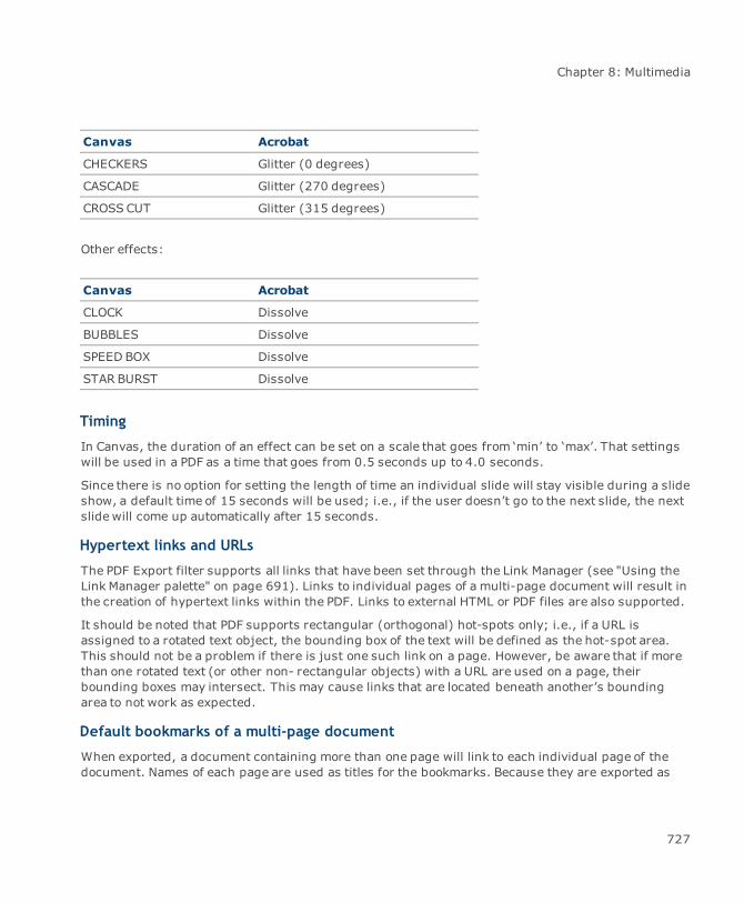
Chapter 8: Multimedia
Canvas Acrobat
CHECKERS Glitter (0 degrees)
CASCADE Glitter (270 degrees)
CROSSCUT Glitter (315 degrees)
Other effects:
Canvas Acrobat
CLOCK Dissolve
BUBBLES Dissolve
SPEED BOX Dissolve
STAR BURST Dissolve
Timing
In Canvas, the duration of an effect can be set on a scale that goes from ‘min’ to ‘max’. That settingswill be used in a PDF as a time that goes from 0.5 seconds up to 4.0 seconds.
Since there is no option for setting the length of time an individual slide will stay visible during a slideshow, a default time of 15 seconds will be used; i.e., if the user doesn’t go to the next slide, the nextslidewill come up automatically after 15 seconds.
Hypertext links and URLs
The PDF Export filter supports all links that have been set through the Link Manager (see "Using theLink Manager palette" on page 691). Links to individual pages of a multi-page document will result inthe creation of hypertext links within the PDF. Links to external HTML or PDF files are also supported.
It should be noted that PDF supports rectangular (orthogonal) hot-spots only; i.e., if a URL isassigned to a rotated text object, the bounding box of the text will be defined as the hot-spot area.This should not be a problem if there is just one such link on a page. However, be aware that if morethan one rotated text (or other non- rectangular objects) with a URL are used on a page, theirbounding boxes may intersect. This may cause links that are located beneath another’s boundingarea to not work as expected.
Default bookmarks of a multi-page document
When exported, a document containing more than one page will link to each individual page of thedocument. Names of each page are used as titles for the bookmarks. Because they are exported as
727

Canvas 12 User Guide
Unicode text each title may contain any letter that is supported by your current locale.
Using Multiple Master PostScript fonts
The PDF Export filter can’t embed Multiple Master fonts. If a Multiple Master font is used in adocument, the PDF filter exports all standard properties of the font; however, it will not embed theactual data of the font, regardless of the current setting in the PDF Export dialog box.
Presentations
You can create Canvas presentations that can be played by other Canvas users or self-running slideshows.
Creating slide shows
When creating a presentation in Canvas, you can save the presentation in two ways:
Canvas file (.CVX): If you save it as a .CVX file, the presentation can be opened by anotherCanvas user.
Canvas Slide Show (.EXE): An .EXE file is a self-running application that can only beexecuted on a Windows platform. You don’t need Canvas to run this file (see "To play theslide show (.EXE):" on page 732).
Remember to first save your presentation as a Canvas file so you can make changes to theoriginal file and view the presentation on either platform.
To create a slide show:
1. Choose File | New and select Presentation as the Type of Document.
2. Use the Document Layout palette to add slides, layers, and specify various options that affecthow the slide show is played (see "Using the Document Layout palette" on page 85 and "Slideoptions" on page 731).
3. Open the Slide Show palette by choosing Layout | Slide Show (see "Slide Show palette" onpage 728).
Slide Show palette
You’ll need to access the Slide Show palette if you want to build a slide show or view a slide show.Choose Layout | Slide Show to open the palette. This is a floating palette that can be kept open tocreate, configure, and play slide shows.
728

Chapter 8: Multimedia
Slide Show palette options
Fit to screen Reduces or enlarges the document’s slides so they fit within the screenarea of the system used to play the slide show. Canvas calculates ascaling factor based on the size of the system’s monitor and theresolution setting.
Loop Causes the slide show to play continuously until you interrupt it. WhenCanvas reaches the end of the document, it begins the slide show fromthe first slide.
Show Pointer Displays a pointer on screen during playback. Enable this option andselect the pointer from the pop-up menu. You can control the pointerwith the mouse during the slide show, so you can indicate importantitems in the presentation.
Advance Every _Seconds
Makes the slide show self-running by advancing from one slide toanother after a specified interval, without any intervention from theoperator. Enter the number of seconds in the text box. The exact timingbetween slides depends on the speed of the system used for playbackand the complexity of the illustrations.
Progressive Build The Progressive Build option in this palette will allow you to play a self-running slide show either layer by layer or slide by slide. While playingyour self-running show, you also have the option to control theprogression of each slide in the show. (see "To play the slide show(.EXE):" on page 732).
Anti-Aliased PlayQuality
Select this option to anti-alias (smooth) vector and text objects duringplayback. If you select “Vector Quality: Anti Aliased” in the ConfigurationCenter, Canvas will anti-alias objects in your documents except whenplaying slide shows.
Build Slide Show Opens the Save As dialog box. Enter the name of the document in the filename field. Ensure that the (.EXE) extension is kept.
Another way to begin this process is to choose File | Save As. If you choose this method,then your presentation will use the options that have been set in the Slide Show palette.
Adding speaker notes
If you are presenting a slide show, speaker notes can help you remember important points ofdiscussion. You can also create these notes for your audience. Each slide can have its own set of
729
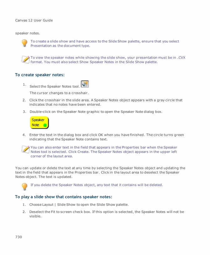
Canvas 12 User Guide
speaker notes.
To create a slide show and have access to the Slide Show palette, ensure that you selectPresentation as the document type.
To view the speaker notes while showing the slide show, your presentation must be in .CVXformat. You must also select Show Speaker Notes in the Slide Show palette.
To create speaker notes:
1. Select the Speaker Notes tool.
The cursor changes to a crosshair.
2. Click the crosshair in the slide area. A Speaker Notes object appears with a gray circle thatindicates that no notes have been entered.
3. Double-click on the Speaker Note graphic to open the Speaker Note dialog box.
4. Enter the text in the dialog box and click OK when you have finished. The circle turns greenindicating that the Speaker Note contains text.
You can also enter text in the field that appears in the Properties bar when the SpeakerNotes tool is selected. Click Create. The Speaker Notes object appears in the upper leftcorner of the layout area.
You can update or delete the text at any time by selecting the Speaker Notes object and updating thetext in the field that appears in the Properties bar. Click in the layout area to deselect the SpeakerNotes object. The text is updated.
If you delete the Speaker Notes object, any text that it contains will be deleted.
To play a slide show that contains speaker notes:
1. Choose Layout | Slide Show to open the Slide Show palette.
2. Deselect the Fit to screen check box. If this option is selected, the Speaker Notes will not bevisible.
730
Chapter 8: Multimedia
3. Click the Play button. The slide show appears on the left side of the screen and the SpeakerNotes on the right side.
Displaying a slide show on two monitors
In order to use this function, you must have the necessary hardware to support two monitors. Referto your system documentation.
If using twomonitors, Canvas displays the slide show on the full screen of the primary monitor. Theslide show and speaker notes are shown in normal view on the secondary monitor.
If you do not know which monitor is primary and secondary, use the Display Options in theControl Panel.
Slide options
In the Options dialog box, you can define slide properties such as names and transitions. To accessthe Options dialog box, open the Document Layout palette (Layout | Document Layout). Then openthe palette menu and select Options.
To set slide transitions:
You can set transitions for the current slide or multiple slides. To apply a transition effect to multipleslides, select the slides in the Document Layout palette and open the Options dialog box as previouslyexplained.
1. To use a transition effect (such as Dissolve or Iris In), select Transition to next slide. If youdo not select this option, the slides simply appear in sequence.
2. Select a transition effect in the pop-up menu. If there are options for the transition effect, theOptions button is available. Click the button to open the Transition Options dialog box.
3. In the Transition Options dialog box, drag the slider to adjust the transition speed fromMin(slowest) to Max (fastest). Select a Direction (if available) and then click OK to return to theOptions dialog box.
4. To preview the transition effect, click Try.
5. Click OK in the Options dialog box to apply the settings to the selected slides.
Once you have finished setting your options, you are ready to save your presentation aseither a Canvas file (.CVX) or Canvas Slide Show (.EXE).
731
Canvas 12 User Guide
Remember to first save your presentation as a Canvas file so you can make changes tothe original file and view the presentation on either platform.
6. Choose File | Save As to open the Save As dialog box.
7. Enter a name in the File Name field.
8. Select either .CVX or Canvas Slide Show (.EXE) for the file format.
9. Click Save.
Viewing slide shows
Canvas Presentations that are saved as Canvas files (.CVX) can be viewed within Canvas. When youplay a Canvas Presentation, Canvas displays the document’s slides in order, using the specifiedtransition timing and effects.
A presentation slide show can be set to automatic mode, in which the slide show plays once and stopsor repeats continuously. Slide changes also can be controlled by an operator. Canvas can show slidesusing a time interval that you specify, or you can control the pace by clicking the mouse to switch tothe next slide whenever you are ready.
To play a slide show in Canvas (.CVX):
1. Choose File | Open and find the Canvas Presentation document (.CVX).
2. Choose Layout | Slide Show to view the Slide Show palette.
3. Click Play on the palette. If “Advance Every _ Seconds” is selected, Canvas changes slides atthe specified interval. Otherwise, click to change slides. Ctrl-click to go back one slide.
4. To stop the slide show, right-click.
While playing a Slide Show within Canvas, you may view each layer in reverse order. To dothis, you must press Ctrl+Shift and click the mouse.
To play the slide show (.EXE):
If the slide show was saved as an .EXE file, you can view it as a self-running application on aWindows platform.
732
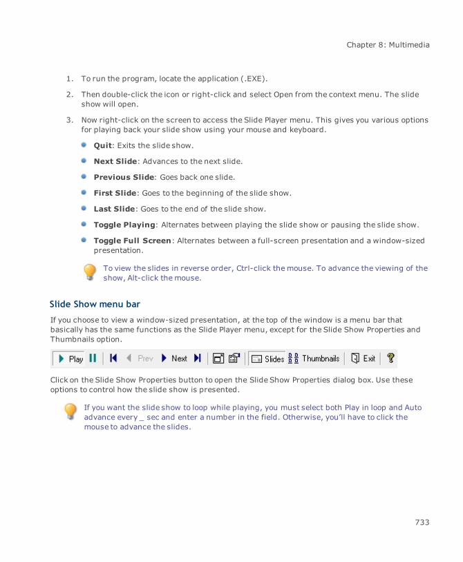
Chapter 8: Multimedia
1. To run the program, locate the application (.EXE).
2. Then double-click the icon or right-click and select Open from the context menu. The slideshow will open.
3. Now right-click on the screen to access the Slide Player menu. This gives you various optionsfor playing back your slide show using your mouse and keyboard.
Quit: Exits the slide show.
Next Slide: Advances to the next slide.
Previous Slide: Goes back one slide.
First Slide: Goes to the beginning of the slide show.
Last Slide: Goes to the end of the slide show.
Toggle Playing: Alternates between playing the slide show or pausing the slide show.
Toggle Full Screen: Alternates between a full-screen presentation and a window-sizedpresentation.
To view the slides in reverse order, Ctrl-click themouse. To advance the viewing of theshow, Alt-click themouse.
Slide Show menu bar
If you choose to view a window-sized presentation, at the top of the window is a menu bar thatbasically has the same functions as the Slide Player menu, except for the Slide Show Properties andThumbnails option.
Click on the Slide Show Properties button to open the Slide Show Properties dialog box. Use theseoptions to control how the slide show is presented.
If you want the slide show to loop while playing, you must select both Play in loop and Autoadvance every _ sec and enter a number in the field. Otherwise, you’ll have to click themouse to advance the slides.
733

Chapter 9: Seismic Data
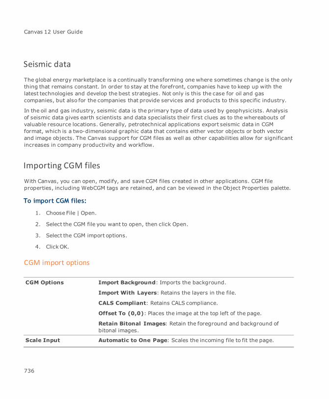
Canvas 12 User Guide
Seismic data
The global energy marketplace is a continually transforming one where sometimes change is the onlything that remains constant. In order to stay at the forefront, companies have to keep up with thelatest technologies and develop the best strategies. Not only is this the case for oil and gascompanies, but also for the companies that provide services and products to this specific industry.
In the oil and gas industry, seismic data is the primary type of data used by geophysicists. Analysisof seismic data gives earth scientists and data specialists their first clues as to the whereabouts ofvaluable resource locations. Generally, petrotechnical applications export seismic data in CGMformat, which is a two-dimensional graphic data that contains either vector objects or both vectorand image objects. The Canvas support for CGM files as well as other capabilities allow for significantincreases in company productivity and workflow.
Importing CGM files
With Canvas, you can open, modify, and save CGM files created in other applications. CGM fileproperties, including WebCGM tags are retained, and can be viewed in the Object Properties palette.
To import CGM files:
1. Choose File | Open.
2. Select the CGM file you want to open, then click Open.
3. Select the CGM import options.
4. Click OK.
CGM import options
CGM Options Import Background: Imports the background.
Import With Layers: Retains the layers in the file.
CALS Compliant: Retains CALS compliance.
Offset To (0,0): Places the image at the top left of the page.
Retain Bitonal Images: Retain the foreground and background ofbitonal images.
Scale Input Automatic to One Page: Scales the incoming file to fit the page.
736

Chapter 9: Seismic Data
%: Select a percentage for scaling the incoming file.
Object Clipping Clip Only If Necessary: This option eliminates clipping rectangles ifthey do not clip any of the objects assigned to them. Those objects arecontained entirely within the clipping area and checking this option willallow Canvas to redraw much faster; however, if any object stripped ofthe clipping rectangles is moved outside that area, they will not beclipped because the clipping rectangle has been removed when settingthis option. Be careful with this option if you want tomove objects in thedocument.
Hard Clipping: This option eliminates objects that are not visible as aresult of clipping.
Render Options Render Document: Select this option to change the color mode orresolution of the file.
Color Mode: Select a color mode.
Pixels/in: Select a resolution in pixels per inch.
Seismic Options Import Only Raw Seismic Data: Select this option to import only theseismograph samples. The subsequent trace objects will not have anywiggles or background images, only those samples. Later, using theSeismic Traces palette, you can create wiggles or background imagefrom those samples. If this option is not selected, the wiggles and/orbackground image will be created on import in accordance to settingsincluded in the CGM file.
Interpolation: Select one of the following:Default: Defined in PIP file.Off Always: No color interpolation.1D Always: Displays the background in baseline direction only.2D Always: Displays the lines in biaxial interpolation.
AdvancedManagement
Collect Lines: Select this option to collect lines.
Skip Degenerate Objects: Select this option to skip degenerateobjects.
Font Match Click this button to open the CGM Font Matching dialog box. The fonts tobe substituted appear in the Original Font column. Select a substitutefont from the drop-down list and click OK.
After you have modified the CGM file, you can then export the file. See "Working With CGM files" onpage 136.
737

Canvas 12 User Guide
Seismic Traces palette
Geologists and earth scientists often have to use seismic files in their studies and various reports.The Seismic Traces palette was designed to allow professionals to examine traces in imported CGMfiles.
To perform any operations on Seismic Trace objects they must be selected. If Seismic Trace objectsare grouped, they have to be ungrouped.
To open the Seismic Traces palette:
ChooseWindow | Palettes | Seismic Traces.
If a trace does not contain seismic data, no wiggle or background image creating can beperformed on the trace. Such a tracemight be imported from a CGM file with a backgroundimage already created; however, if the user erases that background image using the Purgebutton, it is only possible to recreate the background image via the Undo command. Refrainfrom performing background image operations on traces that do not contain seismic data.
Control panel
The following icons are used to control the display or convey information regarding seismic traces:
Click this icon to display wiggles; click again to hide wiggles
Click this icon to display background image; click again to hide background image
Click this icon to adjust wiggle display accuracy
Click this icon to select all trace objects on current page
Icon indicating that all selected traces have seismic data
Icon indicating that only some of the selected traces have seismic data
Icon indicating that none of the selected traces have seismic data
738

Chapter 9: Seismic Data
Wiggle options
The Seismic Traces palette offers a range of ways to visualize wiggles. The Wiggle options sectioncontains the following controls:
Lobes: For both positive and negative lobes, you can hide them, reverse them, and assignthem a color.
Wiggle resampling: Select a resampling method from the menu, Current, Linearapproximation, or Replicate points. If you don’t want to change the resampling method whenchanging other Wiggle options, select Current in the Wiggle resampling menu.
Click Apply to apply any changes to the selected traces. Click Purge to purge all wiggles.
Group of traces in their originalrepresentation (linear approximation)
After changing colors and resamplingmethod (replicate points)
To help better display dense plots Canvas can try to adjust accuracy with which to display wiggles.This will lower the exactness of the display but will help creating a clearer picture. The adjustedaccuracy feature is triggered (if selected) when the magnification is below 100%.
739

Canvas 12 User Guide
Dense plot displayed withoutadjusted accuracy (at zoom 50%)
Same fragment with adjustedaccuracy(at zoom 50%)
Background options
Another way of visualizing seismic data can be accomplished by creating a background image inwhich color is directly derived from the data. The image representation of the data is created byassigning colors to maximum, minimum, and 0 value of the data. All other data values fall in positive(between maximum value and 0) and negative (between 0 and minimum value) ranges, number ofwhich is set by the user. The same is donewith the color space between colors assigned tomaximum, minimum, and 0 values. Each range of values is then assigned a color that will representthe range in the image. Colors can be later interpolated between neighboring traces to create asmoother image.
A color legend can also be created. The number of notches on the legend can be set by enteringvalues in the Positive steps and Negative steps fields. Themaximum number of notches is 20.
Click Apply to create a new image from data contained in selected traces using current options. ClickPurge to erase the image already created for the selected traces.
The following images show image representation of the same fragment of data using different colorranges.
740

Chapter 9: Seismic Data
If themajority of the data is concentrated within a narrow range of values as compared to the fulldata range between maximum and minimum data values, the image created will appear blank sincethe data will be assigned only a few colors from the available spectrum. If this occurs, you can obtainthe histogram of data contained in the traces and then set a window of values within which imagecolors will be scaled. All values falling outside this window will be assigned a minimum or maximumcolor.
Image created with colors scaled to full data range
To address this problem, you should obtain the histogram of the data by selecting traces and clickingthe Update button. Then, you set a window of values by entering a window of values and thenclicking Set. You would then select Histogram’s amplitude window from the Color scales tomenu.Click Apply.
741
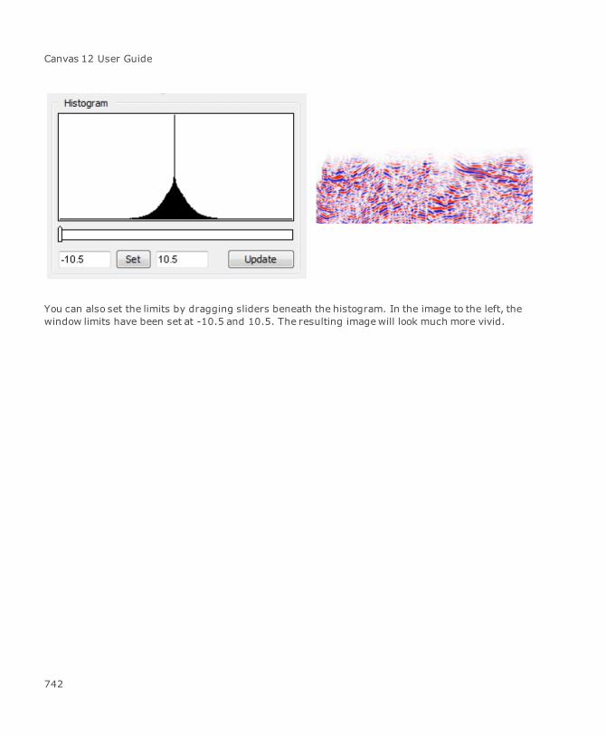
Canvas 12 User Guide
You can also set the limits by dragging sliders beneath the histogram. In the image to the left, thewindow limits have been set at -10.5 and 10.5. The resulting imagewill look much more vivid.
742
Chapter 10: Visualization And Analysis
Canvas 12 User Guide
Data acquisition, visualization and analysis
Canvas has the ability to accurately measure, analyze, and export digital images that may contain upto 32 bits per channel of data.
Specialized imaging instrumentation within the medical, geological, and other related scientificindustries often creates image or data files that may contain more than 16 bits of data per grayscalechannel. Canvas now combines its professionally engineered technology core with a number of newinterface improvements that target the need to study and analyze this information.
Working with DICOM images
Commonly used in medical imaging, DICOM (DIC) files can be imported into Canvas for further study.Combine the DICOM import filter with the Canvas tools, various image filters and adjustments alongwith its slide show capabilities to create dynamic medical presentations. You can even export yourfindings to HTML.
DICOM import options
A DICOM filemay consist of one or many images. Canvas can read DICOM files as follows:
RGB images are imported as RGB and grayscale are imported as grayscale.
Indexed images are converted to RGB.
Depending on the image’s range, it will be converted to 8 bit, 16 bit, 32 bit, or 64 bit images.
To import DICOM files:
1. Choose File | Open, File | Place, or Image | Import.
2. In the DICOM Import Options dialog box, select one or more of the following:
Distribute among layers: Select this option to place each image on a separate layer inthe same document.
Stack together: Select this option to place the images on top of each other.
Create spreadsheet: Select this option to create a matrix of the various images. Definethe number of rows and columns.
Create animation/slide show: Select this option if you want to create a presentation orexport as an AVI file.
744
Chapter 10: Visualization And Analysis
File Version: Select either Default, DICOM v.3, or DICOM v.2 (NEMA).
Image Structure: Select either Default, Little Endian, or Big Endian.
Window Center/Width: This option allows you to adjust the level settings of the imageso you can optimize image contrast upon import for improved image analysis. Select Nonefrom the menu if you want no level setting adjustment. Select Default to use the valueswithin the image itself. Select New Preset to create a user-defined setting.
If you try to open or place more than one image, the FrameAlignment options are enabled.
To create a user-defined setting:
Enter values in the Center and Width fields. Click Save and enter a name in the dialog box.
When creating settings, try to use a name that relates to its use.
To apply a user-defined setting:
Open the menu and select the setting and then click OK.
RAW file format
RAW format is a flexible file format for transferring documents between different applications andcomputer platforms. It is basically an import/export format rather than a storage format.
A RAW file has no predefined format, not even for image width and height, palettes, etc. RAW formatconsists of a stream of bytes describing the color information in the file.
Exporting RAW files
You have two options when exporting to RAW format: binary (.raw) or text (.txt).
To export to RAW format (binary):
1. Choose File | Save As.
2. Select RAW Image (binary) as the format.
3. Click Save.
4. In the Raw Image Export Options (binary) dialog box, select your settings.
5. Click OK.
745
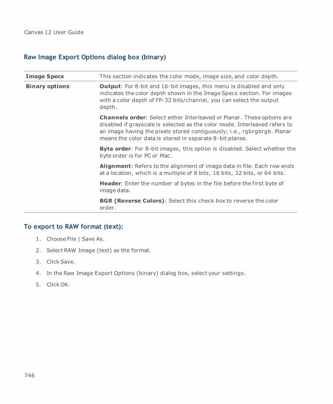
Canvas 12 User Guide
Raw Image Export Options dialog box (binary)
Image Specs This section indicates the color mode, image size, and color depth.
Binary options Output: For 8-bit and 16-bit images, this menu is disabled and onlyindicates the color depth shown in the Image Specs section. For imageswith a color depth of FP-32 bits/channel, you can select the outputdepth.
Channels order: Select either Interleaved or Planar. These options aredisabled if grayscale is selected as the color mode. Interleaved refers toan image having the pixels stored contiguously; i.e., rgbrgbrgb. Planarmeans the color data is stored in separate 8-bit planes.
Byte order: For 8-bit images, this option is disabled. Select whether thebyte order is for PC or Mac.
Alignment: Refers to the alignment of image data in file. Each row endsat a location, which is a multiple of 8 bits, 16 bits, 32 bits, or 64 bits.
Header: Enter the number of bytes in the file before the first byte ofimage data.
BGR (Reverse Colors): Select this check box to reverse the colororder.
To export to RAW format (text):
1. Choose File | Save As.
2. Select RAW Image (text) as the format.
3. Click Save.
4. In the Raw Image Export Options (binary) dialog box, select your settings.
5. Click OK.
746
Chapter 10: Visualization And Analysis
Raw Image Export Options dialog box (text)
Image Specs This section indicates the color mode, image size, and color depth.
Text options Format: Select fromComma delimited, Tab delimited, Space delimited,Colon delimited, or Semicolon delimited.
Output: For 8-bit and 16-bit images, this menu is disabled and onlyindicates the color depth shown in the Image Specs section. For imageswith a color depth of FP-32 bits/channel, you can select the outputdepth.
Channels order: Select either Interleaved or Planar. These options aredisabled if grayscale is selected as the color mode. Interleaved refers toan image having the pixels stored contiguously; i.e., rgbrgbrgb. Planarmeans the color data is stored in separate 8-bit planes.
BGR (Reverse Colors): Select this check box to reverse the colororder.
Importing RAW files
You have three options when importing RAW files: binary (.raw), text (.txt), or comma separatedvalues file (.csv).
Binary (.raw) is themost common selection since devices, like microscopes or various measuringequipment, produce binary (.raw) files.
To import RAW files:
1. Choose File | Open.
2. Select Raw Image as the format and navigate to the file.
3. Click Open.
4. In the Raw Image Import Options dialog box, select your settings.
5. Click OK.
747
Canvas 12 User Guide
Raw Image Import Options dialog box
Input Data Canvas normally detects the appropriate option. You can select eitherradio button.
Image specs Mode: Select the color mode for the image: Grayscale, RGB, BGR, CMYK,LAB, or Multichannel.
Source: Select the source image type: 8 Bits/Channel, 16 Bits/Channel,16 Bits/Channel signed, or Float-32 Bits/Channel.
Target: Select the target image type: 8 Bits/Channel, 16 Bits/Channel,or Float-32 Bits/Channel.
Height & Width: You must know these specifications to properlyimport the raw image.
Channels: The number of color channels depends on the image’s colormode.
Resolution: Set the resolution for the image. Use either pixels/in orpixels/cm.
Quantity: Indicates the number of images stored in the file.
Gap: Indicates the number of bytes from the end of one image to thebeginning of the next.
Channels order: Select either Interleaved or Planar. These options aredisabled if grayscale is selected as the color mode. Interleaved refers toan image having the pixels stored contiguously; i.e., rgbrgbrgb. Planarmeans the color data is stored in separate 8-bit planes.
Binary options Byte order: Indicates whether the file originates from a PC or Mac.
Header: Enter the number of bytes in the file before the first byte ofimage data.
Alignment: Refers to the alignment of image data in memory. Each rowends at a memory location, which is a multiple of 8 bits, 16 bits, 32 bits,or 64 bits.
Image types and filters
Canvas supports 8-bit, 16-bit, and floating point (32-bit) images. All image filters are available for 8-bit images. For Binary filters, the 8-bit image must be grayscale (see "Binary filters" on page 749).
748
Chapter 10: Visualization And Analysis
Regarding 16-bit and floating point (32-bit) images, various image filters and adjustment commandsare available (see "Available filters and adjustment commands" on page 749).
Image modes
If you are working with various image types and need to determine or convert images, choose Image| Mode.
8 Bits/Channel: Indicates an 8-bit image. If working with 16-bit or 32-bit images, selectthis option to convert to an 8-bit image.
16 Bits/Channel: Indicates a 16-bit image. Select this option to convert to a 16-bit image ifworking with another image type.
FP-32 Bits/Channel: Indicates a floating point (32-bit) image. A floating point imagerefers to any array of data that is visualized. Select this option to convert to a 32-bit image ifworking with another image type.
You must convert an 8-bit or 16-bit image to grayscale to enable the FP-32 Bits/Channeloption.
The following table indicates the filters that can be used with each type:
Image type Available filters and adjustment commands
16-bit Average blur, Gaussian blur, Add Noise, Despeckle, Dust & Scratches,Median, High Pass, Maximum, Minimum, Arithmetic, Binary Logic,Expression, Image Math, Colorize, Invert, Levels, Curves,Brightness/Contrast, Convolve, Hue/Saturation (RGB only), Color Balance(RGB only)
FP (32-bit) Average blur, Median, Minimum, Maximum, Arithmetic, Expression, ImageMath, Convolve, Colorize
Binary filters
These commands can be applied to 8-bit grayscale images. For the Dilate, Erode, Open, and Closecommands, you must specify the number of iterations in a dialog box. Iterations refer to the numberof repetitions of a chosen filter.
749
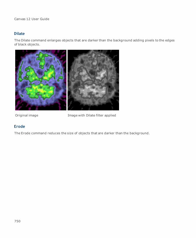
Canvas 12 User Guide
Dilate
The Dilate command enlarges objects that are darker than the background adding pixels to the edgesof black objects.
Original image Imagewith Dilate filter applied
Erode
The Erode command reduces the size of objects that are darker than the background.
750

Chapter 10: Visualization And Analysis
Original image Imagewith Erode filterapplied
Make Binary
The Make Binary command converts a grayscale image, or the current selection, to values of either 0or 255 so that you can apply a binary command to the image.
Close
The Close command is a combination of the Dilate and Erode commands. When selected, the filterfirst performs a dilation and then the erosion. The goal of the filter is to smooth objects by filling ingaps in the image.
751
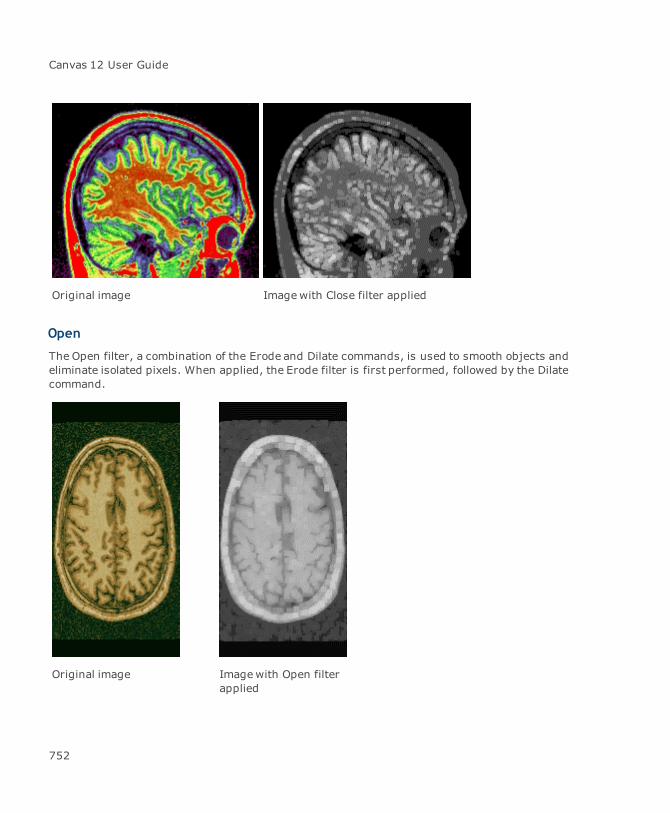
Canvas 12 User Guide
Original image Imagewith Close filter applied
Open
The Open filter, a combination of the Erode and Dilate commands, is used to smooth objects andeliminate isolated pixels. When applied, the Erode filter is first performed, followed by the Dilatecommand.
Original image Imagewith Open filterapplied
752
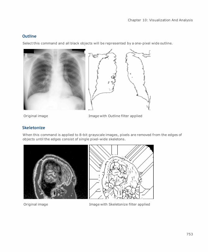
Chapter 10: Visualization And Analysis
Outline
Select this command and all black objects will be represented by a one-pixel wide outline.
Original image Imagewith Outline filter applied
Skeletonize
When this command is applied to 8-bit grayscale images, pixels are removed from the edges ofobjects until the edges consist of single pixel-wide skeletons.
Original image Imagewith Skeletonize filter applied
753

Canvas 12 User Guide
Distance Map
When applied, this filter creates an Euclidean distance map (EDM). The result of the command is thatevery black pixel is replaced with a gray value that is equivalent to the black pixel’s distance from theclosest white pixel.
Original image Imagewith Distance Map filterapplied
Ultimate Points
This filter is used on images to which the Distance Map filter has been applied to find the UltimateEroded Points (UEPs) of the Distance Map.
Imagewith Distance Map filterapplied
Imagewith Ultimate Point filterapplied
754

Chapter 10: Visualization And Analysis
Scientific filters
Canvas features scientific filters that can be used to analyze 8-bit, 16-bit, and floating point (32-bit)images. See "Available filters and adjustment commands" on page 749 to verify which scientific filteris available for the various image types.
To access the Scientific filters:
Choose Image | Filter | Scientific.
Arithmetic
The Arithmetic Filter contains commands that add (subtract, multiply, etc.) a value to each pixel inthe active image or selection. When the result value is above or below the legal range of the image'sdata type, the value is reset to themaximum/minimum value.
To apply an Arithmetic filter:
1. Select the image object (or part of it with a Marquee or Lasso tool) or place it in edit mode.
2. Open the Operation menu to choose a command.
Select the Preview check box so you can see the result before clicking OK.
3. Enter a value in the Value numeric field.
4. Click OK.
The Operation menu contains the following commands:
Operation Explanation
Add Adds a value to the image. With 8-bit images, results greater than 255are set to 255.
Subtract Subtracts a value from the image. With 8-bit and 16-bit images, resultsless than 0 are set to 0.
Multiply Multiplies the image by the specified real value. With 8-bit images,results greater than 255 are set to 255. With 16-bit signed images,results greater than 65,535 are set to 65,535.
Divide Divides the image by the specified real value. Attempts to divide by zerowill be ignored.
Minimum Pixels in the image with a value less than the specified value are replacedby the value.
755
Canvas 12 User Guide
Operation Explanation
Maximum Pixels in the image with a value greater than the specified constant arereplaced by the value.
Square root Destination pixel is equal to the square root of source pixel.
Square Destination pixel is equal to the square of source pixel.
Gamma Applies the function f(p) = (p/255)^gamma*255 to each pixel (p) in theimage or selection, where 0.1 <= gamma <= 5.0. For RGB images, thisfunction is applied to all three color channels. For 16-bit images, theminimum and maximum are used for scaling instead of 255.
Log Applies the function f(p) = log(p) * 255/log(255) to each pixel (p) in theimage or selection. For RGB images, this function is applied to all threecolor channels. For 16-bit images, the minimum and maximum are usedfor scaling instead of 255.
Binary Logic
The Binary Logic Filter contains commands that perform bitwise operations or shift bits accordinglywithin a pixel.
The Operation menu contains the following commands:
Operation Explanation
Or Performs a bitwise OR operation on a source pixel and an argument.
And Performs a bitwise AND operation on a source pixel and an argument.
Xor Performs a bitwise XOR operation on a source pixel and an argument.
Left Shift/Right Shift Performs a logical shift; it shifts all the bits in the pixel left or rightaccording to the value specified in edit box and inserts 0.
Colorize
The Colorize filter is used to assign colors or gradients to a chosen range of values. Depending on theimage type, 8-bit, 16-bit, or floating point (32-bit), you can use either absolute values orpercentages.
For floating point (32-bit) images, the Absolute values check box is automatically selected so you willuse Absolute values.
756
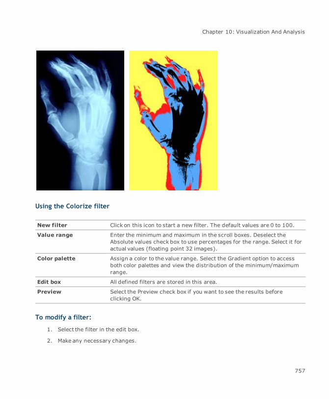
Chapter 10: Visualization And Analysis
Using the Colorize filter
New filter Click on this icon to start a new filter. The default values are 0 to 100.
Value range Enter the minimum and maximum in the scroll boxes. Deselect theAbsolute values check box to use percentages for the range. Select it foractual values (floating point 32 images).
Color palette Assign a color to the value range. Select the Gradient option to accessboth color palettes and view the distribution of the minimum/maximumrange.
Edit box All defined filters are stored in this area.
Preview Select the Preview check box if you want to see the results beforeclicking OK.
To modify a filter:
1. Select the filter in the edit box.
2. Make any necessary changes.
757

Canvas 12 User Guide
To delete a filter:
1. Select the filter in the Edit box.
2. Click the trash can icon.
To save a setting:
1. Define the filters as indicated previously.
2. Click on themenu icon.
3. Select Save settings.
4. In the dialog box, enter a name for the setting.
You can save an unlimited number of settings.
To load a setting:
1. Click on themenu icon.
2. Select Load settings.
3. Choose a setting.
Image Math
This filter performs an arithmetic and logical operation between two color channels and applies theresult to another color channel.
The Operation menu contains the following commands:
Operation Explanation
Add Adds a value to the image. With 8-bit images, results greater than 255are set to 255.
Subtract Subtracts a value from the image. With 8-bit and 16-bit images, resultsless than 0 are set to 0.
Multiply Multiplies the image by the specified real value. With 8-bit images,results greater than 255 are set to 255. With 16-bit signed images,results greater than 65,535 are set to 65,535.
Divide Divides the image by the specified real value. Attempts to divide by zerowill be ignored.
Minimum Pixels in the image with a value less than the specified value are replacedby the value.
758
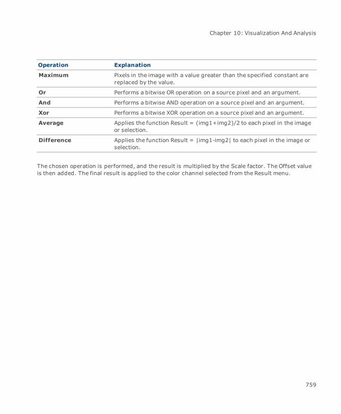
Chapter 10: Visualization And Analysis
Operation Explanation
Maximum Pixels in the image with a value greater than the specified constant arereplaced by the value.
Or Performs a bitwise OR operation on a source pixel and an argument.
And Performs a bitwise AND operation on a source pixel and an argument.
Xor Performs a bitwise XOR operation on a source pixel and an argument.
Average Applies the function Result = (img1+img2)/2 to each pixel in the imageor selection.
Difference Applies the function Result = |img1-img2| to each pixel in the image orselection.
The chosen operation is performed, and the result is multiplied by the Scale factor. The Offset valueis then added. The final result is applied to the color channel selected from the Result menu.
759

Canvas 12 User Guide
Original image 1st operand: GreenOperation: Xor2nd operand: RedScale: 2.0Offset: 0.0Result: Green
To apply the Image Math filter to multiple images:
1. Select the images.
2. Apply the filter by choosing Image | Filter | Scientific | Image Math.
760
Chapter 10: Visualization And Analysis
3. In the Filter operation mode dialog box, select the options you want to use.
4. Click OK.
Expression
The Math Expression filter can be used to perform mathematical equations on a color channel.
To use the Math Expression filter:
1. Select the color channel from the Target menu. The available color channels depend on theimagemode; i.e., CMYK, RGB, etc.
2. Define the mathematical equation using the Categories scroll box and their related items.
3. Double-click on an item tomake it appear in the Expression field.
The lower portion of the dialog box indicates the correct syntax and shows an exampleof the expression.
4. Click Apply to see the effect. Clicking Revert stops the effect on the color channel.
5. Click OK to permanently apply the effect to the channel.
To apply the Math Expression filter to multiple images:
1. Select the images.
2. Apply the filter by choosing Image | Filter | Scientific | Expression.
3. In the Filter operation mode dialog box, select the options you want to use.
4. Click OK.
Convolve
The Convolve filter can be used to apply a spatial convolution on an image or selected image area. Theconvolution is performed according to a kernel, which is basically a matrix whose size you define interms of width and height in pixels. Note that only odd numbers can be used to define the size of thekernel. Themaximum is 11 pixels and the minimum, 3 pixels.
761
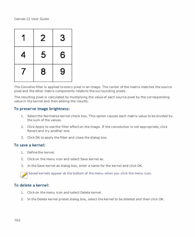
Canvas 12 User Guide
The Convolve filter is applied to every pixel in an image. The center of the matrix matches the sourcepixel and the other matrix components relate to the surrounding pixels.
The resulting pixel is calculated by multiplying the value of each source pixel by the correspondingvalue in the kernel and then adding the results.
To preserve image brightness:
1. Select the Normalize kernel check box. This option causes each matrix value to be divided bythe sum of the values.
2. Click Apply to see the filter effect on the image. If the convolution is not appropriate, clickRevert and try another one.
3. Click OK to apply the filter and close the dialog box.
To save a kernel:
1. Define the kernel.
2. Click on themenu icon and select Save kernel as.
3. In the Save kernel as dialog box, enter a name for the kernel and click OK.
Saved kernels appear at the bottom of themenu when you click themenu icon.
To delete a kernel:
1. Click on themenu icon and select Delete kernel.
2. In the Delete kernel preset dialog box, select the kernel to be deleted and then click OK.
762

Chapter 10: Visualization And Analysis
To load a kernel:
1. Click on themenu icon.
2. Select the kernel that you want to apply.
To paste a kernel:
Before pasting a kernel, ensure there is a space between the values.
1. Copy the kernel from its source (e.g., Notepad).
2. Click the Paste icon.
Original image Imagewith Convolve filterapplied
Accessing image data
Canvas contains important features that allow you to analyze an image’s pixel values and measurevarious image properties: Image Data Viewer tool, View Data command, and Image Measurementcommand.
763

Canvas 12 User Guide
Image Data Viewer tool
You can quickly view raw data within an image object using either the Image Data Viewer tool or ViewData command. These tools are designed so you can quickly view image data “on the fly”. In addition,you can copy this data to a .txt file or spreadsheet application for further analysis.
To use the Image Data Viewer tool:
1. Select the Image Data Viewer tool from the Marquee tools in the Toolbox.
2. Drag it across the image. The Image Data Viewer dialog box opens showing the individualpixel values for the selected area.
To use the View Data command:
1. Make a selection using the Marquee tools.
2. Click the View Data button in the Properties bar to open the ImageData Viewer dialog box.
764

Chapter 10: Visualization And Analysis
Image Data Viewer dialog box
Display Hexidecimal: Refers to the base-16 number system, which consists of16 unique symbols: the numbers 0 to 9 and the letters A to F.
Signed decimal: Integer value which can have both positive andnegative values.
Unsigned decimal: Integer value with value of zero or greater (nonegative numbers).
FP 2-Decimal: Refers to a floating point value with 2 digits followingthe decimal.
FP 4-Decimals:Refers to a floating point value with 4 digits followingthe decimal.
FP 8-Decimals: Refers to a floating point value with 8 digits followingthe decimal.
Channel Select a color channel from the menu. The available channels depend onthe image mode; i.e., RGB, grayscale, CMYK, etc.
Copy Data ToClipboard
Click this icon to export the data to a spreadsheet or other file foranalysis.
Refresh Data Click this icon to update the data.
Lock Click this icon to lock the dialog box and save the data view. Once locked,you can take the Image Data Viewer tool and select another data sample.Another dialog box will open so you can compare data.
Left Indicates the position of the first pixel in relation to the left side; i.e., 43would be the 43rd pixel from the left.
Top Indicates the position of the first pixel in relation to the top; i.e., 29would be the 29th pixel from the top.
Width Indicates the width of the selected area in pixels.
Height Indicates the height of the selected area in pixels.
An alternative method to using the Image Data Viewer tool is to export the image as a .txt fileusing the RAW file export filter (see "Exporting RAW files" on page 745). However, althougheffective, the RAW export method may be time-consuming if analyzing several images anddata is required immediately.
765

Canvas 12 User Guide
Image measurement
The Image Measurement dialog box contains information about the selected image or selectedregions within an image.
To view an image’s image measurement at any time:
Choose Image | Image Measurement.
Image Measurement dialog box
List This list contains the various image properties that are being measured.You can customize the data by clicking the Configure button andselecting the properties to be measured.
Each selected region within an image has its own column of data.
If you want to label the image or selected regions, select the LabelObjects check box. The label corresponds to the column number.
Configure Click this button to open the Image Measurement Properties dialog box.Select the properties that you want to appear in the list.
Copy Select an column of data and click this button to copy the imagemeasurements so you can paste them in a spreadsheet or text editingapplication.
Copy All Click this button to copy all columns of data for multiple selections. Youcan paste them in a spreadsheet or text editing application.
Histogram Click this button to launch the Histogram dialog box for a single columnof data.
Histogram All Click this button to launch the Histogram dialog box for multipleselections.
766
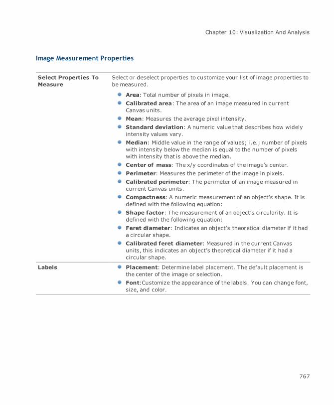
Chapter 10: Visualization And Analysis
Image Measurement Properties
Select Properties ToMeasure
Select or deselect properties to customize your list of image properties tobe measured.
Area: Total number of pixels in image.Calibrated area: The area of an image measured in currentCanvas units.Mean: Measures the average pixel intensity.Standard deviation: A numeric value that describes how widelyintensity values vary.Median: Middle value in the range of values; i.e.; number of pixelswith intensity below the median is equal to the number of pixelswith intensity that is above the median.Center of mass: The x/y coordinates of the image’s center.Perimeter: Measures the perimeter of the image in pixels.Calibrated perimeter: The perimeter of an image measured incurrent Canvas units.Compactness: A numeric measurement of an object’s shape. It isdefined with the following equation:Shape factor: The measurement of an object’s circularity. It isdefined with the following equation:Feret diameter: Indicates an object’s theoretical diameter if it hada circular shape.Calibrated feret diameter: Measured in the current Canvasunits, this indicates an object’s theoretical diameter if it had acircular shape.
Labels Placement: Determine label placement. The default placement isthe center of the image or selection.Font:Customize the appearance of the labels. You can change font,size, and color.
767

Appendices
Canvas 12 User Guide
System Requirements
Hardware
Intel® Pentium® 4 or better
512 MB RAM installed (1 GB RAM recommended)
700 MB free hard disk space (1.5 GB recommended)
16-bit color or higher (True color recommended)
1024x768 or higher screen resolution recommended
DVD drive – to install from the installer disk
Software
Microsoft®Windows® XP Home or Professional operating system (with Service Pack 2installed), Windows Vista® or Windows® 7
Microsoft® Internet Explorer® 6.0 (7.0 or higher recommended) – to view the Help
A
770

Index
Canvas 12 User Guide
_
_blank 693
_parent 693
_popup 693
_self 693
_top 693
{
{first page} 692
{Frame#1} 692
{last page} 692
{next page} 692
{page-bottom} 692
{page-top} 692
{Page#1} 692
{previous page} 692
{Sheet #1} 692
{Slide#1} 692
1
1 side command 371
16-bit image 749
2
2 sides command 371
3
3-D effects 383
3D effects 387
8
8-bit image 749
A
absolute constraints 366
absolute paths 697
accessing individual tools 25
acquiring
files as proxies 554
Photoshop files 148
proxies 554
see also importing 131
Acrobat (PDF) files 136
activate font history 114
activating channels 508
activating document window 55
add noise filter 480
add points to curve 333
add property dialog box 222
add unit dialog box 75, 117
add visibility mask command 429
adding
anchor points 330, 332
dictionary words 628
layers 90
metatags 718
pages 90
772
Index
paintbrushes 421
speaker notes 730
tangent line handles 330
toolbar buttons 127
units 75
waveforms 336
adding units 117
Adobe Photoshop file format 148, 502
again command 54
AI export options dialog box 136
Airbrush tool 413
align command 181
align palette 181
align to object (inks) 248-249
aligning
objects 31, 181
text 594
text vertically 596
alignment guides and objects 81
all (image selection) command 484
alpha channels 503
see channels 506
Alt key 11
anchor points
adding 332
corner 339
deleting 332
selecting 159, 330
smooth 339
tangent lines 339
Angle Dimensioning tool 358
angle preference 116
animated GIF
creating 712
onion-skinning 71
save as 713
animated GIF options
anti-aliasing 713
auto crop 713
differential frames 714
erase previous frame 713
individual palette per frame 713
infinite loop 714
interlaced 713
optimize frames 714
transparent background 713
annotations tools
shape type 309
using 308
anti-alias image 187
anti-aliased Canvas objects 107
anti-aliased Clipboard 107
anti-aliasing rotated bitmaps 543
append brushes command 421
appending
brushes 423
inks 226
web buttons 712
773

Canvas 12 User Guide
applying
arithmetic filter 755
attribute style 204
binary logic filter 756
convolve filter 761
envelope effect 385
envelope template 384
envelope to images 546
frame ink 632
frame stroke 632
image filters 32
imagemath filter 758
math expression filter 761
outline ink 632
outline stroke 632
preset inks 229
scientific filters 755
SpriteEffects 30
tapered ends 267
text formats 563
Arc 3 Points tool 289
Arc Radius tool 290
Arc tool 286, 294
Area Dimensioning tool 359
arithmetic filter 755
arrange icons command 56
arranging
objects 180
toolbar buttons 127
arrow styles icon 26
arrowheads
adding to strokes 264
using different ones on each end ofstroke
266
arrows
arrow manager 281
arrow tab 264
customizing 281
presets 264
removing 267
artistic effects
bevel 537
crystallize 532
lens flare 533
oil painting 534
stained glass 535
artistic filters 532
assign position dialog box 76
assigning
names 89
URL to slice 708
X/Y positions 76
assigning properties to object 211
attaching comments to objects 208
attribute styles
applying 204
attribute styles palette 204
deleting 205
774

Index
loading 204
saving 204
attributes
changing text 618
finding text 618
pasting 169
Attributes manager 100
attributes palette 271
auto-scroll to selection 110
auto cache images option 103
auto correct 111, 620
Auto Curve tool 322
auto trace command 458
Auto Trace settings 460
autoword select 114
automatic selection method 445-446
autosave 106
AutoSnap palettes 25
average blur command 474
average blur filter 475
AVI 150
B
background color 423
background color icon 494
background inks 632
background options, seismic 740
background updates, preventing 105
backup documents 105
Baseline Dimensioning tool 358, 360
baseline position, text 584
Basic Smart Lines tool 305
bevel effect 537
bevel line joins 275
Bézier curve paths 348
binary filters 749
close 751
dilate 750
distance map 754
erode 750
make binary 751
open 752
outline 753
skeletonize 753
ultimate points 754
binary logic filter 756
bind position handles 639
bind text command 638
bind to path command 396
binding text
removing bind 641
to a circle 641
to vector objects 637
black & white image mode 437
black body palette 439
blend command
bind to path 382
creating borders 383
775

Canvas 12 User Guide
dynamic 382
objects 381
point to point 382
rainbow colors 382
Blend tool 414, 513
blending
colors 235
gradient inks 238
blur filters 474
blur more filter 474-475
Blur tool 418
bold font style 584
borders
border command 498
creating with blend command 383
trimming image borders 451
both axes (flip) command 644
Bound text commands 641
bounding box
description 161
restoring after rotation 193
breaking
break composite command 346
paths 330
brightness/contrast command 467
bring to front command 180
brush icon 420
brush options command 421
brush options dialog box 421
brush pointers 106
brushes
adding to palette 421
appending 423
creating 421
defining with selection 422
deleting 422
editing 420
loading from disk 423
modifying 420
saving to disk 422
selecting 421
brushes palette 421
Bucket tool 413
Burn tool 418
butt end cap
see flat end cap 275
buttons, web 708, 712
C
cache object command 102-103
cache options 102
caching
paint objects 32
text objects 33
vector objects 31
calculate command 547
Calculate values command 220
Calendar tool 303
776
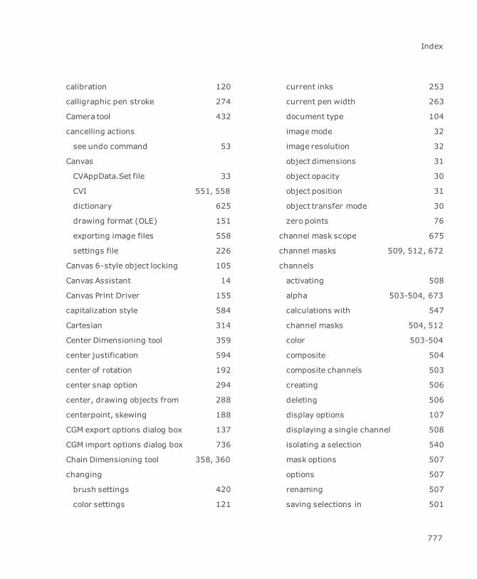
Index
calibration 120
calligraphic pen stroke 274
Camera tool 432
cancelling actions
see undo command 53
Canvas
CVAppData.Set file 33
CVI 551, 558
dictionary 625
drawing format (OLE) 151
exporting image files 558
settings file 226
Canvas 6-style object locking 105
Canvas Assistant 14
Canvas Print Driver 155
capitalization style 584
Cartesian 314
Center Dimensioning tool 359
center justification 594
center of rotation 192
center snap option 294
center, drawing objects from 288
centerpoint, skewing 188
CGM export options dialog box 137
CGM import options dialog box 736
Chain Dimensioning tool 358, 360
changing
brush settings 420
color settings 121
current inks 253
current pen width 263
document type 104
imagemode 32
image resolution 32
object dimensions 31
object opacity 30
object position 31
object transfer mode 30
zero points 76
channel mask scope 675
channel masks 509, 512, 672
channels
activating 508
alpha 503-504, 673
calculations with 547
channel masks 504, 512
color 503-504
composite 504
composite channels 503
creating 506
deleting 506
display options 107
displaying a single channel 508
isolating a selection 540
mask options 507
options 507
renaming 507
saving selections in 501
777

Canvas 12 User Guide
channels palette 504, 506
character attributes 612
character formatting
font styles 584
fonts 582
horizontal and vertical scaling 589
kerning 585
preventing changes to 613
special characters 622
type size 583
type styles 606
character spacing 586
check proxies command 556
Chinese fonts 114
choke trap 202
choosing document type 68
Circle 3 Points tool 288
Circle Radius tool 288
Circle Redline tool 206
circles, drawing 286
classic arrows
bottom 282
editing 282
full 282
hollow 282
top 282
witness 282
clean up by name command 35
clean up command 35
clean up palettes command 26
clear command 164
clear font history 114
clearing customized settings 125
clearing inks 226
clearing print area 68
clipart
placing;symbols
placing 399
clipboard
copying objects to 165
definition & use 164
OLE 152
pasting into selections 495
clipping paths
applying effects to 376
creating 374
definition 374
editing 376
from text 643
removing 375
showing and hiding 375
cloning options
see Rubber Stamp tool 413
close filter 751
closed paths 333
closing
documents 68
palettes 26
778
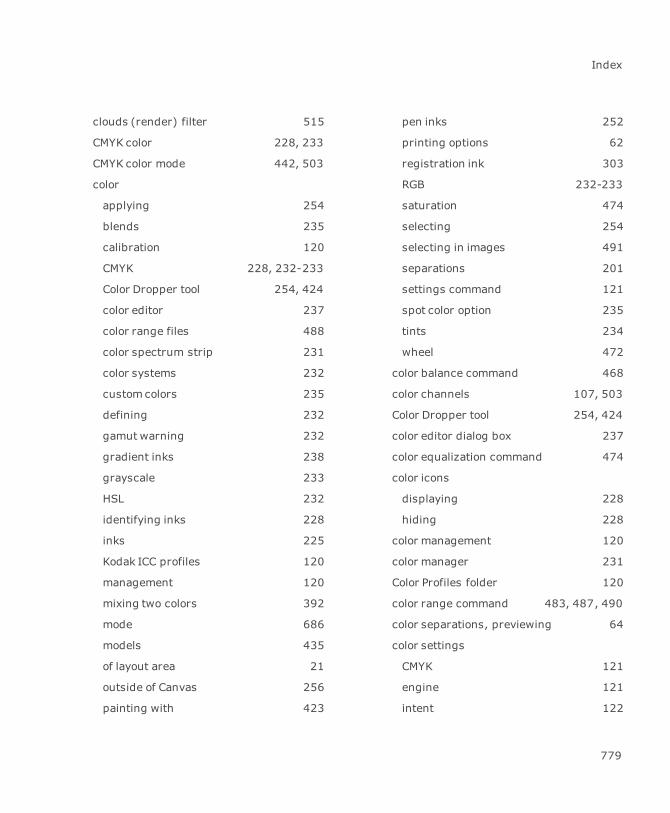
Index
clouds (render) filter 515
CMYK color 228, 233
CMYK color mode 442, 503
color
applying 254
blends 235
calibration 120
CMYK 228, 232-233
Color Dropper tool 254, 424
color editor 237
color range files 488
color spectrum strip 231
color systems 232
customcolors 235
defining 232
gamut warning 232
gradient inks 238
grayscale 233
HSL 232
identifying inks 228
inks 225
Kodak ICC profiles 120
management 120
mixing two colors 392
mode 686
models 435
of layout area 21
outside of Canvas 256
painting with 423
pen inks 252
printing options 62
registration ink 303
RGB 232-233
saturation 474
selecting 254
selecting in images 491
separations 201
settings command 121
spot color option 235
tints 234
wheel 472
color balance command 468
color channels 107, 503
Color Dropper tool 254, 424
color editor dialog box 237
color equalization command 474
color icons
displaying 228
hiding 228
color management 120
color manager 231
Color Profiles folder 120
color range command 483, 487, 490
color separations, previewing 64
color settings
CMYK 121
engine 121
intent 122
779
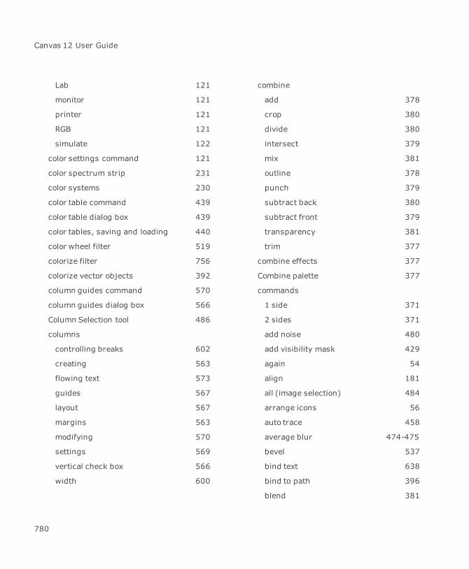
Canvas 12 User Guide
Lab 121
monitor 121
printer 121
RGB 121
simulate 122
color settings command 121
color spectrum strip 231
color systems 230
color table command 439
color table dialog box 439
color tables, saving and loading 440
color wheel filter 519
colorize filter 756
colorize vector objects 392
column guides command 570
column guides dialog box 566
Column Selection tool 486
columns
controlling breaks 602
creating 563
flowing text 573
guides 567
layout 567
margins 563
modifying 570
settings 569
vertical check box 566
width 600
combine
add 378
crop 380
divide 380
intersect 379
mix 381
outline 378
punch 379
subtract back 380
subtract front 379
transparency 381
trim 377
combine effects 377
Combine palette 377
commands
1 side 371
2 sides 371
add noise 480
add visibility mask 429
again 54
align 181
all (image selection) 484
arrange icons 56
auto trace 458
average blur 474-475
bevel 537
bind text 638
bind to path 396
blend 381
780

Index
blur 474
blur more 474
border 498
both axes (flip) 644
break composite 346
brightness/contrast 467
bring to front 180
cache object 102-103
calculate 547
Calculate values 220
check proxies 556
choosing 11
clean up 35
clean up by name 35
clean up palettes 26
clear 164
color balance 468
color equalization 474
color range 487
colorize 392
column guides 570
combine 377
comments & markup 208
Configuration Center 97
configure fine kerning 586
continue spell check 628
contract 497
convert to paths 194, 343, 647
copy 164, 171
copy as 96 dpi 166
copy as image 166-167
copy at 4X 167
copy at 8X 167
copy options 165
copy to layers 181
create 408
crop 449
crop and fit to sheet 78
crystallize 532
curves 470
custom (filter) 541
cut 164, 494
date 604
date stamp 604
de-interlace 482
defloat 496
delete 90
delete view 44
desaturate 467
despeckle 482
detach 511
detach mask 677, 679, 684
disperse 94
display options 101-102
dock all palettes 34
dock palettes when closed 34
document setup 129, 134
duplicate 164, 171
781
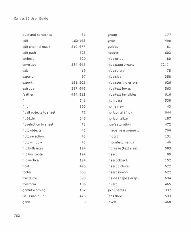
Canvas 12 User Guide
dust and scratches 481
edit 162-163
edit channel mask 510, 677
edit path 328
emboss 520
envelope 384, 645
exit 19
expand 497
export 131, 502
extrude 387, 646
feather 494, 512
fill 541
find 163
fit all objects to sheet 78
fit Bézier 348
fit selection to sheet 78
fit to objects 43
fit to selection 43
fit to window 43
flip both axes 194
flip horizontal 194
flip vertical 194
float 495
footer 603
fractalize 393
freeform 186
gamut warning 102
Gaussian blur 475
grids 80
group 177
grow 490
guides 81
header 603
hide grids 80
hide page breaks 72, 74
hide rulers 75
hide size 358
hide spelling errors 626
hide text boxes 563
hide text invisibles 616
high pass 538
home view 43
horizontal (flip) 644
horizontalize 187
hue/saturation 472
imagemeasurement 766
import 131
in context menus 46
increase (text size) 583
insert 89
insert object 152
insert picture 622
insert symbol 622
inside shape (wrap) 634
invert 465
join (paths) 337
lens flare 533
levels 468
782

Index
links 153
live curve editing 324
load (image selection) 501
lock 181
loose (kerning) 586
loosen (kerning) 586
loosen (leading) 590
loosen fine kerning 586
make composite 346
math expression 2-D plot 314
maximum 540
median 481
minimum 540
motion blur 476
move 179
new 68, 128, 134
new channel mask 510, 674
new image from selection 498
new view 43
none (selection) 484
normal (kerning) 586
object specs 197
offset 524
offset path 374
oil painting 534
open 47, 130
open document layout palette 86
open page navigator palette 85
outline path stroke 345
output resolution 688
overprint 203
page numbering 605
page setup 66, 72
paragraph rules 597
paste 164, 171
paste and place 164, 169
paste attributes 169
paste into 494
paste link 153
paste special 153, 629
path to selection 492
place 49, 130, 630
posterize 463
print 61, 64
print preview 64
printer setup 72
properties 56
proxy info 555, 557
put away palettes 26
quit 19
radial blur 477
redo 54
reduce (text size) 583
reduce points 348
refresh 40
remove effects 186, 374, 449, 454
removewrap 634
render 430-431
783

Canvas 12 User Guide
repeating 54
repel options 636
replicate 171
resolution 456
revert 55
ripple 526
rotate 192, 644
rulers 75
save 50
save (image selection) 501
save as 50, 129, 134, 502
save to web 719
scale 195, 449
scale bar 79
scale by area/perimeter 196
select 162
select all 160
selection to path 499
send to back 180
send to guide layer 82
send to layers 181
set document scale 78
set tab length 35
shadow 394, 645
sharpen 479
sharpen edges 479
sharpen more 479
show added words 628
show channels 503-504, 512
show grids 80
show page breaks 72, 74
show rulers 75
show size 357
show spelling errors 626
show text boxes 563
show text invisibles 616
show toolbox 22
show/hide docking bar 33
show/hide guides 81
show/hide text flow bars 574
show/hide toolbar 27
show/hide transparency preview 672
shuffle down 180
shuffle up 180
similar 490
Smart Mouse 366
smooth 498
smooth (paths) 319
solarize 521
spell check document 627
spell check selection 627
spherize 530
spread 203
stackwindows 56
stained glass 535
Statistics by property 219
threshold 463
tight (kerning) 586
784
Index
tighten (kerning) 586
tighten (leading) 590
tighten fine kerning 586
tile across 56
tile down 56
time 604
time stamp 604
total page count 605
trace contour 523
Treat as point object 77
trim 451
trim to path 452
twirl 529
type 589
uncache object 104
undo 53, 106
ungroup 177
unlink proxy 556
unlock 181
unsharp mask 480
unsmooth (paths) 319
update proxies 558
vanishing point 294, 371
verify document 13
vertical (flip) 644
very loose (kerning) 586
very tight (kerning) 586
view data 764
view fonts 582
wireframe 102
zoomblur 478
zoom in/out 41
commands, choosing 11
comment attributes dialog box 210
comments & markup command 208
Comments & Markup palette 209
Commission Internationale d’Eclairage(CIE)
442
composite channels 503-504
composite paths 346
Computer Graphics Metafile (CGM) for-mat
136
concentric circles
converting to paths 343
drawing 295
Concentric Circles tool 296
Configuration Center 97-98
configure fine kerning command 586
configuring dimension objects 361
Connection Point tool 305-306
constraints
see also snap options 292
context menu 46, 162, 329, 421, 672
continue spell check command 628
contract command 497
contrast
adjusting 467
creating high-contrast images 463
Control key 11
785

Canvas 12 User Guide
convert curve to simple paths 344
convert to lens command;commands
convert to lens 660
convert to paths com-mand
194, 329, 343,647
convolve filter 761
copy as 96 dpi 166
copy as image command 166-167
copy at 4X command 167
copy at 8X command 167
copy command 164, 171
copy options command 165
copy to layers command 181
copying
anti-aliasing 166
attributes 170
attributes of objects 169
by dragging 179
into selections 495
object properties 217
objects 164
objects to layers 181
text objects 616
copying lenses;SpriteEffects
copying lenses 660
corner anchor points 329, 339
corner radius, rounded rectangle 290
create backup when saving 105
create brushes 421
create command 408
create image dialog box 409
create object at viewpoint com-mand;commands
create object at viewpoint 663
creating
animated GIFs 712
attribute style 204
basic shapes 286
callouts 309
channel masks 509-510, 674
channel masks from selections 512
channels 506
classic arrow 282
composite paths 346
customarrowheads 281
customneon strokes 277
dimension objects 358
flowcharts simple 308
forms 576
keyboard shortcuts 126
lenses;lenses
creating;SpriteEffects
creating lenses 659
new channels 505
new documents 68
new inks 231
objects from selections 498
paint objects 406-408
786
Index
pattern inks 250
proxies 551
sections 568
shadows 645
slices 699
Smart Lines 305
special vector objects 295
symbol inks 247
texture ink 249
transparency effects 509
transparency fades 513
vector masks 680
vector objects 286
creating Favorite inks 251
creating lens object;making lensobject;lens object
659
creating transparent background 429
crop and fit to sheet command 78
crop command 449
crop marks 302
Crop tool 450, 452
cropping
constraining 455
images 450
paint objects 32
vector objects 335
with the selection tool 455
cropping images 450
crystallize effect 532
Ctrl key 11
Cube tool 297
cubes, drawing 295
current inks 253
current strokes 259, 263
Curve tool 317, 320
curves
adding anchor points 332
adding segments 332
closing and opening 333
deleting segments 332
drawing 320
curves command 470
curves dialog box 470
cusp anchor points 329
custom
color tables 439
filters 541
inks in pop-up palettes 235
views 43
custom (filter) command 541
customcontrols dialog box 154
customize dialog box
add buttons to toolbar 127
clear all 125
fonts and sizes 126
inks 125
keyboard shortcuts 126
opening 124
787
Canvas 12 User Guide
strokes 125
customize rulers 117
customizing dashes 283
customizing dimension objects 361
customizing pen strokes 272
cut command 164, 494
cutting and pasting
into selections 495
objects 164
text 616
text objects 616
CVI (Canvas Image File) format 551
D
Darken transfer mode 686
dash preference 100
dash styles icon 26
dashes
customizing 283-284
dash manager 284
presets 266
removing 267
date command 604
date stamp command 604
date, inserting in documents 604
DCS format 141
DCS information 133, 719
de-interlace filter 482
default
for new documents 68
inks 253
strokes 259
type attributes 580
define brush command 421
define properties dialog box 211
defining units 117
defloat command 496
delete brush command 421
delete command 90
delete view command 44
deleting
anchor points 329, 332
channel masks 511
channels 506
dictionary words 628
objects 164
path segments 332
preset inks 226
preset strokes 261
sections 571
Smart Mouse constraints 367
tangent lines 330
text 616
deleting alpha channels 505
deleting attribute style 205
deleting channel mask 512
deleting Favorite inks 251
788
Index
deleting slices 706
deleting tabs 588
deleting units 118
desaturate command 467
deselecting
in images 484
objects 160
text 616
despeckle filter 482
detach mask command 511, 679
detaching channel masks 511
dialog balloons 303
dialog box
add property 222
add unit 75, 117
AI export options 136
assign position 76
brush options 421
CGM export options 137
CGM import options 736
color editor 237
color settings 121
color table 439
column guides 566
comment attributes 210
Configuration Center 97-98
create image 409
curves 470
customcontrols 154
customize 124
define properties 211
DICOM import options 744
document properties 718
duotone curves 443
duotone options 442
DWG& DXF import 138
export TIFF 148
Expression Builder 221
guides 82
hue/saturation 472
imagemeasurement 766
indexed color 438
insert 91
kerning specifications 586
levels 470
make proxy 552-553
math expression 2-D cartesian plot 314
math expression 2-D polar plot 314
modify unit 117
new mask 510
new standard definition 365
paragraph rules 598
PDF & PS import 135
raw image export options 746
raw image import options 748
render image 431
replicate & position 176
ripple 526
789
Canvas 12 User Guide
rotate 187, 543
save AVI options 151
scale options 77
select properties to display 218
slice divider 706
speaker note 730
Startup 14, 19
SVG options 150
tab 588
view comments 209
wave configuration 336
Diameter Dimensioning tool 358
DICOM import options dialog box 744
dictionary, spelling 625
digital camera 132, 719
dilate filter 750
dimension objects
attributes 363
changing attributes 363
editing 360
extensions 365
gaps 365
standards 365
text properties 363
text styles 364
tolerance 365
units 365
dimension properties
add 362, 365
arrows 361
display units 361
edit 362
leaders 361
outside lines only 362
postfix 361
prefix 361
remove 362
standard 362
text always centered 364
text display 362
tolerance 361
units 361
use fill color for text 364
use secondary units 362
value 361
witness lines 361
dimensioning tools 358-359
configuring leaders 361
customizing 360
types described 360
Dimensioning tools 361
dimensions
displaying while drawing 357
linking tomeasured objects 364
Direct Edit Lasso tool 159
Direct Edit Selection tool 159
Direct Group Selection tool 159
Direct Selection tool 159
790
Index
disable AutoSnap palettes 25
disable Smart Toolbox 22
disperse command 94
display options command 101-102
display options manager 102
display preferences
color mode 687
interpolation 108
object caching 109
transparency 109
vector quality 108
display redraw 40
displaying
color icons 228
gamut warnings 102
rulers 75
selected object type 161
slide show on two monitors 731
slide shows 732
spelling errors 626
text flow bars 574
wireframe views 102
distance map filter 754
distort
see envelope command and skewingobjects
386
distributing objects 181
dithering options 439
dividing slices 706
dock all palettes command 34
dock palettes when closed command 34
docking tool palettes 22
document layout palette 85
document properties dialog box 718
document setup command 129, 134
document size 69
document type 69
document units 70, 72
documents
active 55
applying section settings 571
Canvas illustration 68, 70
Canvas presentation 68, 71
Canvas publication 68, 70
closing 68
columns 568
comments 206
creating 68
discarding changes 55
display modes 102
formatting text 581
GIF animation 71
keywords 57
layout 82, 97
margins 73
moving objects in 181
navigation controls 21
opening 47
791

Canvas 12 User Guide
orientation 70, 73
page layout 73
paper color 73
placing 49-50
printing 58
properties 56
rulers and scale 74
saving as web pages 714
scrolling 40
setting up 72
size 69
spell checking 625
statistics 57
substituting fonts 48
templates 71, 128
two-sided 73
types of 68
units 70
viewing 39, 43
zooming 41-42
Dodge tool 418
Dogleg Connector Smart Lines tool 305
don’t show plug-in host warning 107
dots per inch 448
double-sided arrowhead 266
double spacing lines of text 590
drag & drop text 113
draw text as Béziers 114
draw with cache option 102
drawing
arcs 286, 289
by numbers 294
circles 286, 288
concentric circles 295-296
cubes 295
curves 321
freehand shapes 319
from center of objects 288
grids 295, 299
lines 286
multigons 300
objects within images 434
ovals 286
paths 321
polygons 317
rectangles 286
rounded rectangles 286
rounded squares 286
Smart Lines 304
spirals 295, 298
squares 286
stars 295
with snap options 292
with snap points 118
drawing aid 366
Drawing Interchange file format 139
drawing preferences
auto-scroll to selection 110
792
Index
when dragging and resizing alwaysshow originals
110
when duplicating objects offset 110
when moving objects offset 110
drawing scale 70, 74, 104
drawing vector objects 286
drop caps 602
drop shadows 394
duotone curves dialog box 443
duotone imagemode 442
duotone inks command 444
duotone options dialog box 442
duplicate command 164, 171
duplicate command preference 110
duplicate with transform 174
duplicating
by dragging 173
channels 505
using modifier keys 173
while rotating 174
while skewing 174
dust and scratches filter 482
DWG & DXF import dialog box 138
DWG import 138
DXF export options 140
DXF import 138
Dynamic Help
closing 37
definition 37
opening 37
dynamic objects
converting to paths 343
inserting into text 625
E
edit channel mask command 510, 677
edit command 162-163
edit mode
definition 162
paint objects 410
paths 328
proxies 555
text 613
edit path command 328
editing
alpha channels 508
arcs 290
channel masks 510, 676
clipping paths 376
comments 208
concentric circles 297
context menus 46
cubes 298
dimension objects 360
extruded objects 390
finding text 618
grids 299
hatch inks 245
793
Canvas 12 User Guide
masks 667
multigons 301
object data 198
objects 162
paint objects 410
paragraph rules 598
pasting attributes 170
pasting into selections 495
paths 324, 328, 339
preserving visibility 514
proxies 554-555
resizing 291
rotated objects 193
Smart Lines 305
specialized objects 329
spirals 299
SpriteEffects 652
tabs 588
text 581, 613
text clipping path 376
vector masks 681
vector objects 328
effect dimensions dialog box;dialog box
effect dimensions 658
effects
blend command 381
clipping paths 376
colorize command 392
combine command 377
drop shadows 394
envelope command 384
extrusion 387
fractalize command 393
offset filter 515
offset path command 374
perspective 371
removing 454
render filter 515
SpriteEffects;objects
SpriteEffects 650
stylize filter 515
three-dimensional 383
embedding (OLE) 154
embedding slide transition effects 726
emboss command 520
enable two-byte script preference 564
enabling symmetrical drag 330
end caps 275
endpoints of paths 333
English measurement units 75
Enter key 11
envelope
Bézier 386
distort 386
double cusp 386
single cusp envelope 386
straight line 386
warp 386
794
Index
envelope command 384, 546
enveloping text objects 645
EPS (Encasulated PostScript For-mat)
140,143
Eraser tool 414, 515
erode filter 750
EXIF image information 132
exit command 19
expand command 497
export commands 131
export submenu 502
export TIFF dialog box 148
export transition effects to PDF 726
exporting
Canvas Image Files 558
files 431
Flash (SWF editor) 720
Flash (SWF player) 720
GIF 143
Illustrator (AI) format 136
images 32
images with channels 502
JPEG 143
PDF 722
RAW files 745
slices 707
SVG 149
text 630
exporting as CGM 137
Expression Builder dialog box 221
extensions, dimension objects 365
extrude command 387
extruded objects, editing 390
extruding text 647
eye color 445
F
facing pages 83
Favorite inks
creating 251
deleting 251
feather command 494, 512
file formats
Acrobat (PDF) 136
Canvas (CVI) 551
Computer Graphics Metafile (CGM) 136
Drawing Interchange Format 139
EPS 140, 143
Graphics Interchange Format (GIF) 143
HTML 714
Illustrator (AI) 136
JPEG 143-144
PDF 722
SWF 720
Tag Image File Format (TIFF) 148
text 151
file installation 120
file placement 120
795

Canvas 12 User Guide
file transfer protocol 692
fill command 541
fill ink icon 26, 223
fill inks
applying to paths 253
applying to text 632
using ink buttons 127
fillet 330
filling objects 253
filter effects 650
filters
add noise 480
applying SpriteEffects;filters
plug-ins 651
average blur 474-475
bevel 537
binary 749
blur 474-475
blur more 474-475
clouds (render) 515
crystallize 532
custom 541
de-interlace 482
description 515
despeckle 481
dust and scratches 481-482
emboss 520
fill 541
Gaussian blur 475
high pass 538
imagemeasurement 766
lens flare 533
maximum 540
median 481
minimum 540
motion blur 476
offset 515, 524
oil painting 534
plug-ins 107
radial blur 477
render 515
ripple 526
scientific 755
sharpen 479
sharpen edges 479
sharpen more 479
solarize 521
spherize 530
stained glass 535
stylize 515
trace contour 523
twirl 529
unsharp mask 480
wheel 519
zoomblur 478
find command 163
find palette
objects tab 163
796
Index
text tab 618
fit all objects to sheet command 78
fit Bézier command 348
fit selection to sheet command 78
fit to objects command 43
fit to selection command 43
fit to window 105
fit to window command 43
Flash
exporting to 720
general options 720
image options 721
SWF editor 720
flat end caps 275
flip both axes command 194
flip horizontal command 194
flip vertical command 194
flipping
objects 194
text 644
flipping objects 186
float command 495
floating point (32-bit) image 749
flow chart boxes 303
flowcharts
simple 308
following hyperlinks 697
font history 114
fonts
applying 581
Chinese 114
finding and changing 620
folder 583
including in EPS files 142
installation tips 583
Japanese 114
Korean 114
preventing changes to 613
selecting 581
specifying 582
styles 584
substituting 48
two-byte 114
type size 583
view fonts palette 582
Western languages 114
foot and inch marks 112
footer command 603
foreground color 423
formatting text with properties bar 581
fractalize command 393
fractals
curves or polygon 394
density 394
wiggle 394
frame ink 632
frame inks 633
797
Canvas 12 User Guide
frame stroke 632
frame strokes 633
frames (animation) 71, 712
freeform command 186
freeform image selections 189
freeformmode
rotating and skewing objects in 186
text 643
vector objects 186
freeform selection 106
Freehand tool 317, 319
from printer option 74
FTP 692
full justification 594
functionality options 104
G
gamut warning 115, 232
gaps, dimension objects 365
Gaussian blur filter 475
general preferences
autosave 106
Canvas 6-style object locking 105
create backup when saving 105
fit to window 105
freeform selection 106
maximize on opening 104
no background updates 105
paste as metaobject 105
scale stroke weight 106
search selection on clicks 105
select across visible layers 105
show information tooltips 105
GIF export options dialog box 143
GIS
new document 69
gradient inks 678
applying 238, 240
creating 238
customizing 238
Gradient Vector tool 240
modifying 243
rainbow 242
styles 239, 242
gradient manager 241
Gradient Vector tool 240
Graphics Interchange Format (GIF) 143
grayscale colors 233
grayscale image mode 437
grayscale palette 439
greeking text 112
grid layers
adding 96
arranging 97
copying 97
definition 95
deleting 97
Gridmaker tool 299
798

Index
grids
converting to paths 343
drawing 295
grids command 80
group command 177
grow command 490
guide layers
adding 96
arranging 96
copying 96
definition 95
deleting 96
guides
columns 567
setting position numerically 82
snap to command 81
guides dialog box 82
H
halftone frequency 116
halftone options 116
halftone screens 458
Hand tool 39
hard crop 450
Hard Light transfer mode 686
hard rotate 543
hard rotate for image 187
hatch inks 244
attributes 245
hatch manager 244
modifying 245
using 244
header command 603
hide
channel mask 511
color icons 228
docking bar command 33
edges command 484
grids command 80
guides command 81
page breaks command 72, 74
properties bar 28
rulers command 75
size command 357
spelling errors command 626
text boxes command 563
text flow bars command 574
text invisibles command 616
toolbar command 27
transparency preview command 672
high pass command 538
home view command 43
horizontal (flip) command 644
Horizontal Align options 184
Horizontal Dimensioning tool 358
Horizontal Distribute options 184
horizontal skewing 188
horizontalize command 187
799
Canvas 12 User Guide
hotkeys 112
HSL color model 233
HTML export options
create new folder 150, 715
file format 715
general 714
generate navigation file 715
layoutmode 715
put images in subfolder 715
separate pages 715
use external style 715
HTTP 692
hue/saturation
brightness 473
colorize option 474
definition 472
dialog box 472
Hyperlink pointer 697
hyperlinks
absolute paths 697
complete URLs 697
defined 690
invalid characters 696
relative paths 693, 697
to e-mail 692
to FTP addresses 692
to HTTP addresses 692
hypertext 690
hypertext transfer protocol 692
hyphenation 600
I
ICC (International Color Consortium)profiles
120
illustration area 668
illustration documents
definition 68, 70
placing 49
setting up 72
Illustrator
export filter 136
export options 136
exporting EPS files to 141
exporting to (AI) file format 136
image channels 502
ImageData Viewer 764
ImageData Viewer dialog box 764
image effect 544
image interpolation
auto 109
bicubic 109
bilinear 108
nearest neighbor 108
imagemath filter 758
imagemeasurement command 766
imagemeasurement dialog box 766
imagemeasurement properties 767
800

Index
imagemodes 749
black & white 436
changing 436
CMYK color 442
definition 435
duotone 442
grayscale 437
Indexed 438
LAB color 442
multichannel 445
RGB color 441
image proxies
definition 551
import command 554
image selections 189
image shadow 645
images
acquiring as proxies 131
acquiring proxies 554
adding visibility masks 428
applying filters 32
auto tracing 458
black & whitemode 437
changing modes 436
changing resolution 457
channels 502
clearing selections 493
copying selections 493
creating 407-408, 432
cropping 448, 455
distorting 530
enveloping 546
feathering selection edges 494
floating selections 495
freeform selections 189
importing 131
in texture inks 248
modifying 32
moving selections 495
pasting into selections 495
preserving visibility 514
printing proxies 59
proxies 551
resampling 456
ripple filter 526
rotating and skewing selections 189
scanning 446
scanning resolution 447
screening 437
selecting areas 485
selections 491, 503
size and resolution 448
trimming borders 451
trimming to path 452
twirl filter 529
images during HTML export 718
import command 131
801

Canvas 12 User Guide
importing
CVI files 131
DICOM files 744
EPS linked files 140
Illustrator 136
images 131
JPEG files 131
Photoshop files 148
proxies 131, 554
RAW files 747
text 629
TIFF files 131
inches measurement units 75
included snap option 294
increase (text size) command 583
indenting text
properties bar 592
type palette 593
indexed color options 438
indexed color palettes 439
information area 39
ink coverage 115
inks
appending 226
applying 256
applying preset 229
arranging 228
blends 235
clearing presets 226
color 225
color editor 237
color tab 225
creating 231
current 253
default 253
default for text 253
fill 253
gamut warning 232
gradient styles 239
gradients 238
hatch 244
hatch manager 244
inks managers 229
loading 226
managers 229
naming 235
Pantone 231
pattern inks 250
pattern manager 251
pen 252
registration color 303
saving 226
selecting 255
sharing 226
spot color option 235
symbol 246
symbol manager 247
text 631
802
Index
texture inks 248
texture manager 249
using ink buttons 127
inks managers 229
inks preference 101
inline (preferences) manager 123
insert
date 604
page numbers 604
time 604
total page count 604
insert command 89
insert dialog box 91
insert object command 152
insert picture command 622
insert symbol command 622
inserting ActiveX controls 154
inserting dynamic object into text 625
insertion point 614
inside shape (wrap) command 634
interlacing in GIF files 147
Internet
FTP 692
HTTP 692
Internet graphics 438
interpolation preferences 108
interrupting display redraw 40
inverse command 490
invert command 465
italic font style 584
J
Japanese fonts 114
Japanese language kit 564
join (paths) command 337
joining curves 330
JPEG EXIF file format 719
JPEG Export Options dialog box 144
JPEG file format 143
justification
justification commands 594
last line of paragraph 600
vertical 596
K
kernel 761
kerning
definition 585
loose 586
normal 586
tight 586
very loose 586
very tight 586
kerning specifications dialog box 586
key object 161
key selection object, alignment 185
keyboard keys 11
Kinked Smart Lines tool 305
803
Canvas 12 User Guide
Knife tool 334
knock outs and overprinting 201
Kodak Color Management System 120
Kodak external tool 120
Kodak ICC profiles 120
Korean fonts 114
KPCMS folder 120
L
LAB color mode 442, 503
LassoSelection tool 159
Lasso tool 189, 486
Lasso tool options 486
launching Canvas 18
layer controls 90-91
layers
definition 83
grid 95
guide 95
options 91
placing 50
sending objects to 181
sharing 94
status bar symbols 39
unsharing 94
laying out a document 82
Layout 85
layout area 21
leading
loosen 590
setting with type palette 591
tighten 590
left justification 594
lens flare effect 533
lens object
changing settings 661
magnification;minimummag-nification, lens;maximum mag-nification, lens
661
settings;properties bar
lens object settings 661
lenses
frozen 664
selecting 163
viewpoints;viewpoints of lenses;Spr-iteEffects
lens viewpoint 662
letter spacing 599
levels command 468
levels dialog box 470
Lighten transfer mode 686
lighting effects in extrusions 389
line joins 274
Line tool 286, 294
Linear Dimensioning tool 359
lines
dashes 284
drawing 286
804

Index
editing 304
painting 413
rules in text 597
transforming 31
Link Info tool 575
Link Manager palette 690, 698
linked text flows 573
linking
(OLE) 154
to pages 695
web buttons 711
links command 153
live curve editing command 324
load (image selection) command 501
load brushes command 421
loading
brushes 423
buttons 711
color tables 440
curve settings 472
ink presets 226
inks 226
shortcut configurations 125
stroke presets 262
web buttons 712
loading and saving duotone infor-mation
444
lock command 181
locking
character attributes 613
objects 181
tool palettes 23
loosen (kerning) command 586
loosen (leading) command 590
loosen fine kerning command 586
lowercase command 584
luminance 673
M
macro files
converting to symbol format 403
Magic Wand tool
seeWand tool 488
magnification in lenses;setting
lens magnification;SpriteEffects
lens magnification 660
magnification levels 41
magnification menu 42
magnification of documents 41
Magnifying Glass tool 41
mailto tag 692
make binary filter 751
make composite command 346
Make Lens button 659
make proxy dialog box 552-553
making callouts 309
making channel masks 510
805

Canvas 12 User Guide
managers
dash 284
gradient 241
inks 229
parallel line 276
pattern 251
strokes 271
managing colors 229
manual registration marks 302
manual selection method 445-446
margins
setting 73
text objects 593
Marker tool 413
Markup Highlighter tool 206
Markup Pen tool 206
Marquee tool 189, 483, 485
masking with paint objects 675
masking with vector objects 681
masks
attaching 675, 681
channel masks 672, 678
detaching 677, 684
transparency 671
using paint objects as 675
vector masks 678, 685
vector objects as 681
master pages 84
math expression 2-D cartesian plot 314
dialog box
math expression 2-D plot 314
math expression 2-D polar plot dialogbox
314
math expression filter 761
maximize on opening 104
maximum command 540
maximum document size 69
measurement units 70
measurements
preferences 117
specifying units 46
using expressions 45
using fractions 45
measuring
objects 358
show size display 357
median filter 481
meta data 56
metatags 718
metric measurement units 75, 564
Microsoft Excel, pasting into 166
Microsoft PowerPoint, pasting into 166
Microsoft Word, pasting into 166
minimum command 540
minor divisions 117
miter joins 274
miter limit 273
806

Index
modes
CMYK color 442
Duotone 442
for Color Dropper tool 254
grayscale 437
images 436
Indexed 438
LAB color 442
multichannel 445
RGB color 441
modifier keys 12
modify brush settings 420
modify icon dialog box 124
modify unit dialog box 76, 117
modifying
attribute style 205
hatch inks 245
images 32
paint objects 32
modifying units 117
monitor 121
motion blur filter 476
mousewith modifier keys 12
move command 179
moving
anchor points 338
dragging objects preference 110
objects 179
segments 338
selections 496
multi-column font menu 114
multichannel image mode 445
Multigon tool 300
multigons, converting to paths 343
multiple master postscript fonts 728
N
navigation controls 21
navigator palette
displaying 44
scrolling 44
view options 45
zooming 44
neon manager 278
neon strokes 277
Neon tool 413
new brush command 421
new channel mask command 510, 674
new command 68, 128, 134
new image from selection command 498
new mask dialog box 510
new standard definition dialog box 365
new view command 43
no background updates 105
noise
add noise filter 480
dust and scratches filter 482
removing noise 481
807
Canvas 12 User Guide
none (selection) command 484
normal mode 685
number format 119
numbering pages 604-605
O
object caching 109
object linking and embedding
definition 151
text files 629
Object Path Editor
angular units (GIS) 369
insert point 371
load Bezier 370
load polygon 370
paste as Bezier 370
paste as polygon 370
save path 371
using 369
object position
moving 31
object properties
assigning 210
common properties 216
define a unit 215
define properties dialog box 211
definition 210
format 215
label 212
palette 211
prompt 215
type 212
value 215
Object Properties Table View palette 217
object shadow 645
Object Side Dimensioning tool 359
object specs command 197
object specs palette
data tab 198
trap tab 201
objects
aligning 181
alignment 181
alignment guides 81
appearance when selected 161
arcs 289
caching 102
circles 288
comments 206
converting EPS to Canvas 140
converting EPSF objects 142
copying 164
cutting and pasting 164
deleting 164
dispersing 94
distributing 181
dragging 179
edit mode 328
808

Index
editing 162
editing data 198
editing rotated 193
embedding 152, 154
extruding 387
fill inks 253
filleting 330
finding 163
flipping 186
fractalizing 393
from auto tracing 458
getting inks from 256
group 685
group transparency 669
grouping/ungrouping 177
linking 153-154
locking and unlocking 181
moving 179
offsetting paths 374
paint 685
paint objects 407
pasting 164
pasting attributes 170
pasting into selections 495
path editing 324
paths 493
repelling text 635
resizing rotated 186
rotating 186
rotating and skewing 186
selecting 158
selecting by type and attributes 163
send or copy to layers 181
skewing 186
slicing 334
SpriteEffects 650
stacking order 180
text 577, 685
transforming 31
trimming 377
types described 158
vector 685
objects, pasting in place 31, 169
Oblique Dimensioning tool 358
offset command 524
offset filter 515
offset path command 374
oil painting effect 534
OLE
Canvas drawing format 151
see object linking and embedding 151
onion-skinning 21, 71, 712
onion-skinning icon 712
opacity 30, 496, 667, 670
defined 668
opacity slider 666
open command 47, 130
open filter 752
809
Canvas 12 User Guide
opening
Canvas Assistant 14
DICOM files 744
documents 47
DWG files 138
DXF files 138
SpriteEffects palette 30
tool palettes 25
OpenType fonts 583
options tab 65
orientation, document layout area 70
orphan and widow lines 601
outline filter 753
outline font style 584
outline ink 632
outline path stroke 345
outline stroke 632
output resolution command 688
output to maximum resolution 116
Oval Marquee tool 485
Oval tool 286, 294
ovals, drawing 286
overprint command 203
overprint object option 201
overset text 573
P
page breaks 72, 74
page controls 90
Page Crop tool 335
page distance 104
page links
creating 696
removing 696
page numbering 604
page orientation 70
page setup command 66, 72
pages
adding and deleting 89
defined 83
facing 83
from printer option 74
hyperlinks to 695
master pages 93
moving 89
options 91
placing 50
printable 87
selecting 88
sending objects to 181
Paint Object Creator tool 407
paint objects
adding visibility masks 428
backgrounds 429, 499
creating 406, 408, 432
cropping 455
defined 406
described 406
810

Index
imagemodes 436
masking with 675
resolution 456
visibility masks 499
Paintbrush tool 413
painting
auto create 408
colors 423
creating objects 407
edit mode 502
Eraser tool 499
modes 425-426
opacity 411
preferences 433
selections 498, 503
with vector objects 434
painting modes
add 548
darken 549
difference 548
hard light 548
lighten 549
multiply 548
normal 548
overlay 548
screen 548
soft light 548
subtract 548
painting preferences
anti-aliased Canvas objects 107
anti-aliased Clipboard 107
color channels 107
painting pointers 106
plug-in host warning 107
plug-ins 107
separate grayscales as black 107
painting tools
Airbrush 413
Blend 414
Blur 418
Bucket 413
Burn 418
Column Selection 485
Crop 452
Dodge 418
Eraser 414
Marker 413
Marquee 483
Neon 413
Oval Marquee 485
Paint Object Creator 407
Paintbrush 413
Pencil 413
pressure-sensitive options 412
RemoteMove 496
Row Selection 485
Rubber Stamp 416
811

Canvas 12 User Guide
Sharpen 419
Smudge 417
Sponge 419
Wand 488
palettes
align 181
attribute styles 204
attributes 229
black body (color table) option 439
blending colors 235
browser safe 439
brushes 421
clean up palettes command 26
color tables 439
combine 377
commands 26
Comments & Markup 209
docking 34
docking bar 33
docking pane 37
docking when closed 34
document layout 85
icons 26
linkmanager 691
navigator 44
object properties 211
Object Properties Table View 217
object specs 197
page navigator;page navigator palette85
presets 223, 260
put away palettes command 26
Seismic Traces 738
slide show 728
spectrum 439
transparency 666
undos 54, 106
view fonts 582
web buttons 709
zoom 41
Pantone colors 231
Pantone inks 232
paragraph alignment 594
paragraph formatting 590, 603
column breaks 602
hyphenation 600
indents 592
justification (alignment) 594
justifying last line 600
leading 590
letter spacing 599
line width 600
rules 597
spacing before and after paragraphs 592
text columns 602
type styles 606
word spacing 599
paragraph leading 591
paragraph rules dialog box 598
812
Index
paragraph spacing 600
parallel linemanager 276
parallel snap option 293
paste and place command 164, 169
paste as metaobject 105
paste attributes command 169
paste attributes command; commands
paste attributes 654
paste command 164, 171
paste into command 494
paste link command 153
paste special command 153, 629
pasteboard 21
pasted text box size 114
pasting
attributes 170
attributes of objects 169
in place 31, 169
into image selections 495
text 630
path points, symmetrical resize 347
Path Text tool 561, 647
path to selection command 492
Path tools 317
paths
adding anchor points 332
adding segments 332
advanced editing 342
changing angle and length 342
closing and opening 333
converting text to 647
converting to selections 493
deleting segments 332
editing 324
filleting 330
from selections 499
joining 337
offsetting 374
pop-up menu for editing 329
reducing points 348
simplifying 348
slicing 334
straightening 342
tangent lines 339
text 647
pattern inks 250
pattern manager
background color 251
editing window 251
foreground color 251
Move tool 251
Pencil tool 251
preview window 251
switch background & foreground 251
patterns, creating with blend com-mand
383
exporting 722
813

Canvas 12 User Guide
halftone settings 724
image options 723
opening 136
PDF options 722
saving as 136
security settings 724
transparency options 724
PDF & PS import dialog box 135
pen ink icon 26, 223
pen inks
applying to objects 252
using ink buttons 127
Pencil tool 413
pens
calligraphic 274
customizing 274
presets 263
Perimeter Dimensioning tool 359
Perpendicular Dimensioning tool 359
perpendicular snap option 294
personality manager 107
perspective effects 371
Photoshop
exporting EPS files to 141
file format 406
format 502
picameasurement units 75
pixel measurement units 75
pixel mode 699
pixels 406
place command 49, 130, 630
placeholders 551
placing
clipart;placing
symbols 399
DICOM files 744
documents 50
DWG files 138
DXF files 138
files 49
images 406
layers 50
pages 50
text 629
plain font style 584
playing slide show 732
playing slide show with speaker notes 730
plug-in acquire modules 446
plug-ins 107
point object 77
point size, type 583
Polar 314
Polygon tool 317, 348
polygons
converting to Bézier curves 348
drawing 317
smoothing 319
posterize command 463
814

Index
PostScript fonts 583
preferences
auto correct 111, 620
dash 100
display 101
font history 114
for text from 123
inks 101
inlinemanager 123
measurements 117
menu bar icons 124
never 123
painting 106, 433
personality manager 107
printing 115
type 112
undo levels 106
user info 110
when moving objects offset 110
presentation documents
definition 71
placing 49
playing 732
presentations
dual monitors 731
speaker notes 730
Speaker Notes object 730
preserve visibility 514
preserving channels 502
preserving visibility in images 514
preset inks 226
preset strokes 260
presets palette 223, 260
preview image, EPSF 141
previews, transparency 671
Print 65
print command 58, 60
print preview command 64
print preview options 65
printable area 68
printable layers 67
printable objects 67
printer setup command 72
printing 58, 60
color separations 201
colors as grays 62
crop marks 302
documents 58
preferences 115
previewing 64
printable option 87
proxies 556
scaled pages 64
SpriteEffects;SpriteEffects
printing 655
thumbnail previews 64
tile option 66
transparency effects 670, 687
815

Canvas 12 User Guide
transparency rendering options 60
unlinked proxies 556
printing preferences
angle 116
halftone frequency 116
halftone options 116
output to maximum resolution 116
use printer’s default 116
properties bar
Break Composite button 346
brush icon 420
combine menu 377
dimension objects 361
document setup 28
Group button 177
Make Composite button 346
showing and hiding 28
tool settings 29
Ungroup button 178
View Data button 764
properties command 56
proxies
acquiring files as 554
creating 552
definition 551
printing 59
replacing an image with proxy 552
proxy info command 555, 557
publication documents
definition 70
placing 49
Push tool 317, 326
put away palettes command 26
Q
quadtone image mode 442
QuickDraw 116
quit command 19
quotation marks, using typographical 112
R
radial blur filter 477
Radius Dimensioning tool 358
raw image export options dialog box 746
raw image import options dialog box 748
Rectangle Redline tool 206
Rectangle tool 286, 294
rectangles, drawing 286
Red Eye Reduction tool 445
redo command 54
reduce (text size) command 583
reduce points command 348
reference point 29
refresh command 40
registration ink 303
Registration Mark tool 302
relative path 697
816
Index
relative Smart Mouse constraints 366
RemoteMove tool 496
remove effects com-mand
186, 374, 448-449,454
removewrap command 634
removing
anchor points 306
anchors 695
hyperlinks 694
proxies 556
red eye 445
web buttons 711
removing units 118
render filter 515
rendering
images 430-431
objects 430-431
render command 430-431
render image dialog box 431
selected areas 432
SpriteEffects;SpriteEffects
rendering 665
SpriteLayer / SpriteEffects 142
rendering intent
absolute colorimetric 122
perceptual 122
relative colorimetric 122
saturation 122
repeating actions
see undo command 54
repel options command 636
repel options dialog box 636
replace selection on paste 114
replacing text 618
replicate & position dialog box 176
replicate command 171
reset brushes command 421
Reshape tool 317, 325
resizing
paint objects 448, 457
text objects 564
using the Properties bar 31
vector objects 291
resolution
Auto function 448
changing 448, 456
choosing 447
defined 447
described 448
for scanned images 447
of new paint objects 407
SpriteEffects;SpriteEffects
resolution 656
retain selected tool 22
reversing actions
see undo command 53
revert command 55
817

Canvas 12 User Guide
RGB color 233
RGB color mode 441, 503
right justification 594
ripple dialog box 526
ripple filter 526
ripple settings 526
rotate command 192, 644
rotate dialog box 187, 543
rotated bitmaps, anti-aliasing 543
rotating
bounding box orientation 193
center of rotation 192
digital images 544
extruded objects 391
freeform selections 190
objects 30, 171, 186
text objects 644
rotation effects in extrusions 389
round end caps 275
round line joins 274
Rounded Rectangle tool 286, 294
rounded rectangles
adjusting corner radius 290
drawing 286
Row Selection tool 486
Rubber Stamp tool 416
rulers
adding units 117
command 75
defining 74
deleting units 118
displaying 75
minor divisions 117
modifying units 117
tear-off 76
rulers controls 75
rules, paragraph 597
S
saturation of colors
hue/saturation command 472
Sponge tool 419
save (image selection) command 501
save as command 50, 55, 129, 134, 502
save AVI options dialog box 151
save brushes command 421
save command 50
save entire document 51
save selection 51
save to web command 719
saving
animations 713
backup documents 105
buttons 711
color tables 440
curve settings 472
envelope template 385
EPS 140
818
Index
GIF 143
image files 131
inks 226
JPEG 143
layers 51
preset inks 226
shortcut configurations 125
stroke presets 262
templates 128
web buttons 711
web pages 714
saving Favorite inks 251
sawtooth wave 336
scale
non-proportional 30
proportional 30
scale bar command 79
scale by area/perimeter command 196
scale command 195, 449
scale options dialog box 77
scale stroke weight 106
scaling
freeform selections 191
images 450
objects 30, 171, 195-196
paint objects 32
when replicating objects 176
scaling options 77
scanning
determining resolution 447
images into Canvas 446
scientific filters 755
Scissors tool 333
scrap file 152
screen frequency 458
screen mode 685
screen rendering manager 108
scrolling documents 40
search selection on clicks 105
searching
text 618
Section tool 570
sections
applying 571
definition 568
deleting 571
modifying 570
segments
see paths 332
Seismic Traces palette 738
select across visible layers 105
select all command 160
select command 162
select properties to display dialog box 218
selecting
anchor points 330
brushes 407, 420
819
Canvas 12 User Guide
Canvas documents 165
columns of pixels 486
fonts 581
group objects 159
in paint objects 159
in text 159
linked text 579
named objects 163
objects 158
objects by type and attributes 163
objects on other layers 105
parts of objects 159
pixels in images 483
rows of pixels 486
selection indicators 161
selection sets 163
text 577, 614
text objects 159
text with keyboard keys 614
tools 23
vector objects 159
with modifier keys 160
with the Lasso tool 486
selecting objects 159
selection mask;SpriteEffects
selection mask 656
selection masks 503
selection to path command 499
selection to path options 500
Selection tool 159, 449
selections
borders 498
contracting 497
converting to paths 499
expanding 497
freeform 189
from paths 492
grow and similar commands 491
in images 485
modifying 497
pasting into 495
smoothing 498
selections in images
adding to 488
clearing 493
color range command 488
copying 493
defloating 496
deleting 493
deselecting 484
feathering 494
floating 495
floating selections 484
hiding and showing edges 484
inverse 490
inversing 488
moving 496
opacity 496
820

Index
pasting 493
selecting all pixels 484
selection border 484
subtracting from 488
send to back command 180
send to guide layer command 82
send to layers command 181
separate grayscales as black 107
separations
color 201
grayscale separation preference 107
set document scale command 78
set tab length command 35
setting
channel mask scope 675
character attributes 612
curve tolerance 320
preferences 97
print area 68
setting up documents 72
settings 29
shadow command 394, 645
shadow font style 584
shape effect 544
sharing
inks 226
layers 94
strokes 262
sharpen edges filter 479
sharpen filters 479
sharpen more filter 479
Sharpen tool 419
sheets, placing 50
Shift key 11
show
added words command 628
channels command 503-504, 512
docking bar command 33
docking pane 36
edges command 484
grids command 80
guides command 81
page breaks command 72, 74
rulers command 75
size command 357
spelling errors command 626
SpriteEffects palette com-mand;commands
show SpriteEffects palette 652
text boxes command 563
text flow bars command 574
text invisibles command 616
toolbar command 27
transparency preview command 672
show information tooltips 105
show original objects 110
showing
presentation with speaker notes 730
821

Canvas 12 User Guide
properties bar 28
toolbox 22
shuffle down command 180
shuffle up command 180
similar command 490
simplifying paths 348
sine wave 336
single-letter shortcut 112
size of paint objects 457
skeletonize 753
skewing
freeform selections 191
objects 186, 188
skewing objects 30
slice divider dialog box 706
slices
alignment guides 702
arrangement commands 707
creating 699
definition 699
deleting 706
deselecting 706
dividing 706
exporting 706
exporting GIF/web buttons 718
HTML export options 707
image options 705
properties 704
remove from selection 706
select this slice 706
select/deselect all 706
Slice Creator tool 700
slice layer 702
Slice Selector tool 700
slicer preferences 700
splitting 706
use spacing GIFs 707
slide show palette 728
slide shows
anti-aliased play quality 729
Build Slide Show command 729
on twomonitors 731
placing slides 50
playing 732
playing self-running 732
progressive build option 729
self-running 729
slide options 731
transitions 731
small caps command 584
smart-crop icon;SpriteEffects
smart-crop icon 658
smart copy 114
Smart Lines 305
adding anchor points 306
changing start/end points 305
Connection Point tool 305-306
creating 305
822
Index
deleting anchor points 306
end direction 305
line type 305
moving anchor points 306
start direction 305
tab length 306
Smart Lines tool
drawing 304
editing 305
Smart Mouse
absolute constraints 366
activating constraint 368
activating constraints 367
adding constraints 367
deactivating constraint 368
deactivating constraints 367
definition 366
deleting constraints 367
indicators 369
modifying active constraint 368
objects within document 369
priority of constraints 368
relative constraints 366
removing constraint 368
snap tolerance 368
within screen 369
within xx pixels 369
Smart Toolbox 22
smooth (paths) command 319
smooth anchor points 329, 339, 348
smooth command 498
Smooth Kinked Smart Lines tool 305
Smooth Polygon tool 317
smoothing video images 482
Smudge tool 417
snap constraints 366
snap option
center 294
included 294
parallel 293
perpendicular 294
tangent 294
vanishing point 294
snap points 118
soft crop 450
Soft Light transfer mode 686
solarize command 521
speaker note dialog box 730
speaker notes 730
Speaker Notes object 730
Speaker Notes tool 730
special characters, typing 622
special copy commands 167
special drawing tools 295
spectrum palette 439
spelling
dictionary 628
pop-up menu 626
823
Canvas 12 User Guide
spell check document command 627
spell check selection command 627
spell checking 625
spherize command 530
spherize settings 531
Spiral tool 298
spirals
converting to paths 343
drawing 295
Sponge tool 419
spot color inks 231, 235
spot colors
in duotone images 443
spot colors in duotone images 443
spread command 203
spread trap 202
Sprite tool 509, 675
SpriteEffects
applying 30, 651, 653
attaching;attach command;detach com-mand;commands
attach;commands
detach;SpriteEffects
detaching 655
duplicating 653
effects area 657
general 650
lenses;lenses
using;effects
lenses 659
mode 655
modifying effects area 657
pasting 654
printing 60
removing 653
saving and loading 654
selecting 163
selection masks;masks
SpriteEffects selection masks 656
sharing documents 665
transferring 655
transferring between objects 171
SpriteEffects palette 30
SpriteLayer effects
properties bar 666
transparency palette 666
SpriteLayers
printing 60
selecting 163
square end caps 275
squarewave 336
squares, drawing 286
stacking command 56
stacking lenses;lenses
stacking order 664
stacking order 180
824
Index
stained glass effect 535
stars, drawing 295
starting Canvas 18
Startup dialog box 14, 19
Statistics by property command 219
status bar 38, 55
straightening curves 330, 342
strikethrough font style 584
strokes
applying custom settings 271
applying tapered ends 267
arrow tab 281
arrows 264
colors 264
customizing 272
dash tab 283
dashes 266, 283-284
definitions 258
deleting presets 261
frame 633
managers 271
neon 260, 277
no pen ink setting 264
no stroke settings 267
parallel 260
parallel lines 275
pen inks 264
pen width 263
presets 260
presets based on objects 272
removing 267
saving and loading presets 262
sharing 262
symbol 280
tapered ends 268
text 259, 633
strokes icon 26
strokes, outline path 345
styles command (font styles) 584
styles, text
applying to text 610
basing styles on others 611
character styles 606
copying from other documents 609
deleting 611
finding and changing 620
modifying 611
paragraph styles 606
stylize filter 515
submenu commands 12
subscript character style 584
subscript command 584
substituting fonts 48
superscript character style 584
superscript command 584
SVG options
create new folder 150
put images in subfolder 150
825

Canvas 12 User Guide
SVG options dialog box 150
symbol ink manager 247
symbol inks
creating 247
definition 246
Symbol Library palette 401, 403
switching directories 399
symbol strokes 280
symbols
converting macro files 403
creating new 401
Symbol Library palette 397
symmetrical drag 347
T
tab dialog box 588
tabs
center 588
comma 588
decimal 588
editing 588
left 588
right 588
tab menu 587
Tag Image File Format (TIFF) 148
tangent lines
adding and removing 330, 341
definition 339
tangent snap option 294
tapered end controls 268
tapered strokes 273
target
_blank 693
_parent 693
_popup 693
_self 693
_top 693
tear-off rulers 76
templates
Canvas documents 71
creating 128
envelope effect 384
testing hyperlinks 697
text
alignment 594
apostrophes 112
as clipping paths 643
attributes 581
background color 581
baseline position 584
binding to a circle 641
binding to paths 637
binds, removing 641
capitalization styles 584
changing 618
changing attributes 618
character attributes 612-613
character styles 606
826

Index
checking text flows 575
color 581
column breaks 602
column width 600
columns 563, 567
converting to paths 343, 647
copying 617
copying text objects 616
default inks 253
deleting 616
drop caps 602
edit mode 613
editing 613
envelope effect 645
exporting 630
extrude effect 646-647
finding 618
flipping 644
flow 569
flow symbol 572
flow symbols 574
flowing 648
font styles 584
fonts 581
fonts, specifying 582
foot and inch marks 112
footers 603
formatting 580
formatting options 32, 581
formatting text flows 579
frame inks 581
freeformmode 643
greeking preference 112
headers 603
horizontal and vertical scaling 589
hyphenation 600
importing 629
in dimension objects 363
in layouts 563
in symbol inks 246
indents 592
inks 581
inks and strokes 631
insertion point 614
justification 581, 594, 600
justifying last line of paragraph 600
kerning 581, 585
layout 567
leader characters 581, 588
leading 581, 590
letter spacing 599
linked flows 573
lowercase 584
moving insertion point 614
overset text 573
page numbering 604
paragraph attributes 590, 603
paragraph rules 597
827

Canvas 12 User Guide
paragraph spacing 592
paragraph styles 606
pasting 617, 630
pasting attributes 170
Path Text tool 561
pen size 581
placing 629
positioning text objects 564
preferences 112
preset formats 580
preventing format changes 613
Properties bar 631
quotation marks 112
repelling 635
replacing 617-618
resizing text objects 564
rotating 643
scaling 195
searching 618
sections 568
selecting 159, 577, 614
selecting linked text 579
setting indents 593
setting tabs 587-588
shadow effects 645
skewing 643
special characters 622
spell checking 625
strokes 259
styles 581
subscript 584
superscript 584
tab position 581
tab types 581
Text Form Field tool 561
Text Format Brush tool 561
Text Link tool 560
text menu commands 580
Text Object tool 560
Text tool 560
Text Unlink tool 560
trapping selected 203
type palette 580
type size 583
typing on paths 647
using Text tool 561
vector effects 643
vertical justification 596
vertical option 566
Vertical Text Object tool 566
Vertical Text tool 565
word spacing 599
wrapping inside objects 634-635
wraps, removing 635
text file format 151
text flow bars 574
Text Form Field tool 561, 576
Text Format Brush tool 561, 563
828

Index
Text Link tool 560, 574, 648
Text Object tool 560, 563
text shadow effects 645
Text tool 560-561
Text Unlink tool 560, 575
texture inks 248
three-dimensional effects 383
threshold command 463
thumbnail previews, printing 64
TIFF, with transparency 149
tighten (kerning) command 586
tighten (leading) command 590
tighten fine kerning command 586
tile across command 56
tile down command 56
tile option 66
time command 604
time stamp command 604
time, inserting in documents 604
tints 234
title command 584
tolerance, dimension text 365
tool palettes 23
docking 22
locking 23
unlocking 23
toolbar
adding buttons 127
arranging buttons 127
customizing 124
general 27
tools
Airbrush 413
Angle dimensioning 358-359
annotations 308
Arc 286
Arc 3 points 289
Arc Radius 290
Area dimensioning 359
Auto Curve 322
Baseline dimensioning 358-359
Baseline Dimensioning 360
Basic Smart Lines 305
Blend 414, 513
Blur 418
Bucket 413
Burn 418
Camera 432
Center dimensioning 359
Chain dimensioning 358-359
Chain Dimensioning 360
Circle 3 Points 288
Circle Radius 288
Circle Redline 206
Color Dropper 254, 424
Column Selection 486
Concentric Circles 296
Connection Point 305-306
829
Canvas 12 User Guide
Crop 452
Cube 297
Curve 317, 320
Diameter dimensioning 358-359
dimensioning 359
Direct Selection 159
Dodge 418
Dogleg Connector Smart Lines 305
Eraser 414, 515
Freehand 317, 319
Gradient Vector 240
Hand 39
Horizontal dimensioning 358
Hyperlink pointer 697
Kinked Smart Lines tool 305
Knife 334
Lasso 189, 486
Line 286
Linear dimensioning 359
Linear Dimensioning tool 359
Link Info 575
Magnifying Glass 41
Marker 413
Markup Highlighter 206
Markup Pen 206
Marquee 189, 483, 485
Multigon 300
Neon 413
Object Side Dimensioning 359
Oblique dimensioning 358
Oval 286
Oval Marquee 485
Page Crop 335
Paint Object Creator 407
Paintbrush 413
palettes 23
Path Text 561, 647
Pencil 413
Perimeter dimensioning 359
Perpendicular dimensioning 359
Polygon 317, 348
Push 317, 326
Radius dimensioning 358-359
Rectangle 286
Rectangle Redline 206
Red Eye Reduction 445
RemoteMove 496
Reshape 317, 325
Rounded Rectangle 286
Row Selection 486
Rubber Stamp 416
Scissors 333
Section 570
Selection 159, 449
Sharpen 419
Slice Creator 700
Slice Selector 700
Smart Lines 304
830
Index
Smooth Kinked 305
Smooth Polygon 317
Smudge 417
Speaker Notes 730
Spiral 298
Sponge 419
Sprite 675
Sprite tool 509
Text 560
Text Form Field 561, 576
Text Format Brush 561, 563
Text Link 560, 574, 648
Text Object 560, 563
Text Unlink 560, 575
Vector Transparency 679
Vertical dimensioning 358
Vertical Text 565
Vertical Text Object 566
Wand 487
tooltips 27
total page count command 605
trace contour command 523
tracking
see letter spacing 599
transfer modes
applying 666
burn 686
darken 686
difference 686
dodge 686
hard light 686
lighten 686
multiply 685
normal 685
overlay 686
properties bar 30
screen 685
soft light 686
transferring attributes
see paste attributes 169
transformed dimensions 188
transforming
objects 174
transform command 393
transparency 30, 149
channel masks 672, 678
combining objects 381
defined 668
opacity 667
paint object background 407
preserving in images 514
preserving visibility 514
preview 671
printing 670, 687
printing options 60
scope 681
scope setting 670
select scope 685
831

Canvas 12 User Guide
SpriteLayer effects 666, 688
transfer modes 685-686
vector masks 678, 685
visibility masks 428, 514
transparency palette 509, 666
transparency preview 672
trap object option 203
trapping
limitations 203
options 201
trap size 203
Treat as point object command 77
trim command 451
trim to path command 452
trimming objects 377
tritone imagemode 442
TrueType fonts 583
TWAIN
acquire image command 447
devices 446
select scanner command 447
twirl filter 529
two-byte fonts 114
two-byte fonts and text 564
two-sided documents
see facing pages 73
type
command 589
hyphenation 600
leading 591
size 583
special characters 622
type palette 593
type styles 606
vertical option 567
type preferences
autoword select 114
clear font history 114
drag & drop text 113
draw text as Béziers 114
enable two-byte script 564
multi-column font menu 114
pasted text box size 114
replace selection on paste 114
smart copy 114
use greeked text 112
use smart quotes 112
when typing into document 112
types of objects 158
U
Ultimate Points filter 754
uncache object command 104
underline font style 584
undo command
definition 53
number of undo levels 106
preference 106
832

Index
undos palette 54, 106
Ungroup 178
ungroup command 177
ungrouping objects converted topaths
346
units of measurement 70, 75, 564
unlink proxy command 556
unlock command 181
unlocking objects 181
unlocking tool palette 23
unlocking tool palettes 23
unshare layers 94
unsharp mask command 480
unsmooth (paths) command 319
untransformed dimensions 188
update proxies command 558
uppercase command 584
URLs
assigning 691
definition 690
invalid characters in 696
linkmanager palette 691
page links 696
removing 694
use greeked text 112
use printer’s default 116
use smart quotes 112
user dictionary
adding words 628
general 625
user info preferences 110
using
Baseline Dimensioning tool 360
Chain Dimensioning tool 360
envelope styles 385
Linear Dimensioning tool 359
Object Path Editor 369
Smart Lines tools 305
Sprite tool 675
using annotations tools 308
using auto cache images option 103
using channels palette 512
V
vanishing point
command 294, 371
snap option 294
vector
path texts 647
perspective effects 371
vector effects
blend command 381
colorize command 392
combine command 377
envelope command 384
fractalizing 393
in text 643
three-dimensional 383
833
Canvas 12 User Guide
vector masks
applying 678
definition 678
paint edit mode 684
vector objects
drawing 286
resizing 291
scope 670
vector quality 108
Vector Transparency tools 679
verify document command 13
vertical
justification 596
option for text 566
skewing 188
vertical (flip) command 644
Vertical Dimensioning tool 358
Vertical Text Object tool 566
Vertical Text tool 565
Vertical Align options 183
Vertical Distribute options 183
vertical text objects 564
video images, smoothing 482
view comments dialog box 209
view controls 98
view data command 764
View Data command 764
view fonts command 582
view fonts palette 582
view magnification 41
viewing
channel mask 511
views, creating custom 43
visibility masks 428, 514
visible layers 67
W
Wand tool 487
wave
sawtooth 336
sine 336
square 336
wave configuration dialog box 336
waveforms 336-337
web browser color palette 439
web buttons 708, 712
web buttons palette 709
web pages
animations 712
creating in Canvas 690
rendering graphics 432
saving 714
Slice Creator tool 700
Slice Selector tool 700
wheel (render) filter 519
when moving objects offset 110
when typing into document 112
widow and orphan lines 601
834
Index
wiggle options, seismic 739
windows
arranging 56
size 104
stack command 56
tile across 56
tile down 56
Windows
systempalette 440
wireframe command 102
word spacing 599
world distance 104
wrapping text
indent from object 594
inside objects 634-635
removing text wraps 635
wrap commands 634
X
X/Y reference point 29
Z
zero points 76
zoomblur filter 478
zoom commands 41
zoom controls 41
zooming documents 41
zooming, navigator palette 44
835

Serial number
© 2006-2010 ACD Systems International Inc. All Rights Reserved Worldwide.