cap 505 relay product engineering tools - abb group · pdf file5.11.2.temp environment...
TRANSCRIPT

CAP 505Relay Product Engineering ToolsInstallation and Commissioning Guide
Industrial IT enabled products from ABB are the building blocks for greater productivity, featuring all the tools necessary for lifecycle product support in consistent electronic form.


1MRS751901-MENIssued: 20.08.2003Version: EProgram revision: 2.2.0
We reserve the right to change data without prior notice.
Relay Product Engineering Tools
Installation and Commissioning Guide
CAP 505
Notice 1The information in this document is subject to change without notice and should not be construed as a commitment by ABB. ABB assumes no responsibility for any error that may occur in this document. Futhermore, pictures are examples only.
Notice 2This document complies with the CAP version 2.2.0.
Notice 3Additional information such as Release Notes and Last Minute Remarks can be found on the program distribution media.
Notice 4ABB Substation Automation regularly provides standard training courses on its main products.The training program is available on the Internet at http://www.abb.com/substationautomation. Please contact your ABB contact for more information.
Trademarks
Intel and Pentium are registered trademarks of Intel Corporation.
Neuron, LON and LONWORKS are registered trademarks of Echelon Corporation.
Acrobat is a registered trademark of Adobe Systems Incorporated
Other brand or product names are trademarks or registered trademarks of their respective holders.
All Microsoft products referenced in this document are either trademarks or registered trademarks of Microsoft Corporation.

Revision History
1MRS751901-MENRelay Product Engineering Tools
Installation and Commissioning Guide
CAP 505
Revision history:Amendments / 20.08.2003:
- RER 109 information removed
- Windows 2000 updates
- Section “Avoiding virtual memory overlap at CAP 505 start-up”
- Section “Troubleshooting destination drive error messages”
- Section “Galaxy Debug window during first start-up”
- Section “ TEMP environment variable”
- New section “Using USB ports”
- New section “Incorrect operating system detected” added
- New section “ Incorrect operating system version added

1MRS751901-MEN CAP 505Relay Product Engineering Tools
Installation and Commissioning Guide
12345
1 Introduction
2 CAP 505 requirements
3 Installation
4 Commissioning
5 Troubleshooting installation


CAP 505ContentsInstallation and Commissioning Guide
Relay Product Engineering Tools1MRS751901-MEN
Contents:1. Introduction ...............................................................................9
1.1. Contents ........................................................................................91.1.1. Software .............................................................................91.1.2. Documentation ...................................................................91.1.3. Hardware .........................................................................10
1.2. Types of CAP 505 orders ............................................................101.2.1. Relay product engineering tools CD-ROM .......................101.2.2. Communication cables .....................................................10
2. CAP 505 requirements ............................................................112.1. Software requirements ................................................................112.2. Hardware requirements ...............................................................112.3. Additional requirements ..............................................................11
3. Installation ...............................................................................133.1. Overview .....................................................................................13
3.1.1. Current version of the product .........................................133.1.2. About older product versions ...........................................133.1.3. Reinstalling an older CAP version on a new version .......133.1.4. Non-forced installation .....................................................133.1.5. Forced installation ............................................................133.1.6. License of the product ......................................................133.1.7. Applications running at install-time ..................................143.1.8. System-wide product interdependencies .........................14
3.1.8.1. Multiple installations of the kernel software.........143.1.8.2. MicroSCADA service...........................................143.1.8.3. MicroSCADA user account .................................143.1.8.4. Kernel incompatibility issues ...............................15
3.2. Software installation procedure outlined .....................................153.3. Installing the software .................................................................17
3.3.1. Starting the installation .....................................................173.3.2. Installation Wizard ............................................................17
3.3.2.1. Welcome .............................................................173.3.2.2. Product License Agreement................................183.3.2.3. System Information 1 ..........................................193.3.2.4. System Information 2 .........................................203.3.2.5. System Information 3 .........................................213.3.2.6. Select - forced installation ...................................223.3.2.7. Select - non-forced installation............................233.3.2.8. Destination Drive.................................................243.3.2.9. Installing ..............................................................253.3.2.10.MicroSCADA user account .................................26

1MRS751901-MENRelay Product Engineering ToolsCAP 505Contents Installation and Commissioning Guide
3.3.2.11.MicroSCADA Service Access Manager.............. 273.3.2.12.Installation completed......................................... 293.3.2.13.System reboot .................................................... 29
3.3.3. Cancelling the installation ................................................ 293.4. CAP 505 program folder ............................................................. 30
3.4.1. Subfolder - Doc ................................................................ 303.4.2. Subfolder - Setup ............................................................. 313.4.3. Subfolder - Tools ............................................................. 323.4.4. Shortcut to the CAP 505 program folder .......................... 32
3.5. Uninstalling the software ............................................................. 32
4. Commissioning ...................................................................... 334.1. Overview ..................................................................................... 334.2. Communication support .............................................................. 33
4.2.1. Protocols .......................................................................... 334.2.2. Channels ......................................................................... 334.2.3. Serial port communication ............................................... 34
4.2.3.1. CAP 505 vs. operating system’s serial port configuration ....................................................... 34
4.2.3.2. Using USB ports ................................................. 344.2.4. LON communication ........................................................ 35
4.2.4.1. LON communication adapters ............................ 354.2.4.2. LON communication software components ........ 35
4.3. Commissioning communication components ............................. 354.4. License tool ................................................................................. 36
4.4.1. General ............................................................................ 364.4.2. License Information dialog ............................................... 364.4.3. Entering license Information ............................................ 364.4.4. Invalid license information ............................................... 37
4.5. System Configuration Tool ......................................................... 384.5.1. General ............................................................................ 384.5.2. Target project .................................................................. 394.5.3. Starting ............................................................................ 394.5.4. System Configuration Tool dialog ................................... 39
4.5.4.1. Serial Ports page ................................................ 404.5.4.2. Serial ports - Adding .......................................... 414.5.4.3. Serial ports - Configuring .................................... 424.5.4.4. Serial ports - Deleting ........................................ 424.5.4.5. LON page ........................................................... 434.5.4.6. Selecting the adapter.......................................... 444.5.4.7. Assigning Subnet/Node settings......................... 454.5.4.8. Saving system configuration .............................. 464.5.4.9. Save configuration - close tool............................ 464.5.4.10.Save configuration - proceed configuration ........ 47
1MRS751901-MEN CAP 505Contents
Relay Product Engineering Tools
Installation and Commissioning Guide
4.5.4.11.Discard configuration changes............................474.6. Installing LON cards ....................................................................47
4.6.1. PCC-10 PC Card commissioning procedure ...................474.6.2. PCLTA-20 Card commissioning procedure .....................48
4.6.2.1. Installation of the PCLTA-20 adapter to Windows 2000 ....................................................................48
4.6.3. PCC-10 PC Card configuration ........................................514.6.3.1. Device driver installation .....................................514.6.3.2. PCC-10 initial configuration.................................52
4.6.4. PCLTA-20 Card configuration ..........................................564.6.4.1. Device driver installation .....................................564.6.4.2. PCLTA-20 initial configuration.............................57
4.6.5. Troubleshooting LON .......................................................614.6.5.1. PCC-10 PC Card preferences.............................614.6.5.2. LON channel configuration failure.......................624.6.5.3. Recovering from failure to configure LON
channels..............................................................634.6.5.4. Overlapping LON communication settings..........65
4.7. Configuring CAP 505 start-up .....................................................664.7.1. Avoiding virtual memory overlap at CAP 505 start-up .....66
5. Troubleshooting installation ..................................................695.1. Incorrect operating system detected ...........................................695.2. Incorrect operating system version detected ..............................695.3. Insufficient user rights to install ...................................................695.4. MicroSCADA service is running ..................................................695.5. Failing to install the MicroSCADA service ...................................705.6. Troubleshooting destination drive error messages ....................705.7. Insufficient disk space .................................................................715.8. No suitable destination drive available ........................................715.9. Incompatible SYS 500 and/or COM 500 installed .......................725.10.Galaxy Debug window during first start-up .................................725.11.Miscellaneous .............................................................................73
5.11.1.Repaired operating system installations ..........................735.11.2.TEMP environment variable .............................................73


1MRS751901-MEN CAP 505Relay Product Engineering Tools
Installation and Commissioning Guide 1. Introduction
1
1. IntroductionThis chapter describes the contents of CAP 505 and the types of orders available for ordering the product.
1.1. Contents
1.1.1. SoftwareCategorization of the software:
Base System Kernel software, additional base tools and services, providing a framework for the object types and tools.
RED 500 Support RED 500 object types and the RED Relay Setting Tool for parameterization of RED 500 series relays. Includes also the relay product engineering tools.
SPACOM Support SPACOM object type and the SPACOM Relay Setting Tool for parameterization of SPACOM series relays.
DR-Collector Tool DR-Collector Tool for working with the disturbance recorders for RED 500 and SPACOM series relays.
IEC-1131 Libraries IEC-1131 libraries for the Relay Configuration Tool.
Initial IEC-1131 Libraries Initial IEC-1131 libraries for the Relay Configuration Tool. These libraries are used in the REF 54x object type's sample application configurations.
Documentation CAP 505 documentation in PDF format and an installer for installing the Acrobat®1 Reader (version 5.0) from Adobe Systems Incorporated. The Acrobat Reader is needed to view the documentation.
This categorization is also present as installation options in the CAP 505 installation application.
1.1.2. DocumentationThe complete list of CAP 505 manuals can be found in the Release Notes, which are also included on the CD.
For the 2.2.0 version of CAP 505, the documentation is available in electronic format only.
1. Acrobat is a registered trademark of Adobe Systems Incorporated.
9

1MRS751901-MENRelay Product Engineering ToolsCAP 5051. Introduction Installation and Commissioning Guide
1.1.3. Hardware
Table 1.1.3-1 Communication hardware
1.2. Types of CAP 505 ordersThere are three different types of orders to place, so you can choose the one that is most suitable for your needs.
1.2.1. Relay product engineering tools CD-ROMContents of delivery
• Program CD, includes CAP 505 program and documentation in electronic format.
Order number
1MRS151017
1.2.2. Communication cablesCommunication cables are listed in Table 1.1.3-1
Order number
The order numbers for the communication cables are listed in Table 1.1.3-1
Relay Type Order numberREF 541, 543, 545REMRECREXA-Series
Opto 1MKC950001-1
REM 610 Opto. *Please contact your nearest ABB representative for availability.
1MRS050698*
SPTO front connectorSPCR front connector
RS 232 - RS 232 SPA-ZP 17A3
SPACOM 100/300 series RS 232 - TTL connector SPA-ZP 5A3SPAC 300/500/600 rear RS 232 - RS 485 SPA-ZP 6A2SACO 16A3, 16D1, 16D3 and 64D4
*Connection cable for SPA-ZP 6A2 to SACO screw terminal
SPA-ZP 21A* andSPA-ZP 6A2
10

1MRS751901-MEN CAP 505Relay Product Engineering Tools
Installation and Commissioning Guide 2. CAP 505 requirements
2
2. CAP 505 requirementsCAP 505 version 2.2.0 sets the following hardware and software requirements on the PC. Notice also the kernel-related dependencies, explained in Section “System-wide product interdependencies” on page 14.
2.1. Software requirements
® Microsoft, Windows NT and Windows 2000 are registered trademarks of Microsoft Corporation.
2.2. Hardware requirements
2.3. Additional requirements
Table 2.1.-1 Software requirements
Item RequiredOperating system Microsoft® Windows NT® 4.0 Workstation.
It is recommended to have Service Pack 5 installed.Microsoft Windows 2000®
It is recommended to have Service Pack 3 installed.Network Operating system Network software installed with at least one
network protocol (e.g. TCP/IP).
Table 2.2.-1 Hardware requirements
Item Minimum RecommendedProcessor 233 MHz or higher Pentium®a
compatible CPU
a. Pentium is a registered trademark of Intel Corporation.
1 GHz or higher Pentium compatible CPU
Memory 128 MB 256 MBDisplay SVGA, 800x600, 256 colours SVGA, 1024x768, 256 coloursFile system Windows NT / Windows 2000 file
system on the installation driveHard disk space 300 MB 500 MBCD-ROM Any device supported by the
operating system. Required for installation
Mouse Any device supported by the operating system
PCI slots One slot for each PCLTA-20 cardPCMCIA slots One slot for each PCC-10 cardNetwork adapter card
Any device supported by the operating system
Table 2.3.-1 Additional requirements
Item DescriptionUser account You must be logged on to the operating system with administrator
rights for the software to be installed successfully. Otherwise the installation is denied.
MicroSCADA service
The MicroSCADA service is not allowed to run in the background during the installation. Otherwise the installation is denied.
11


1MRS751901-MEN CAP 505Relay Product Engineering Tools
Installation and Commissioning Guide 3. Installation
3
3. Installation
This chapter describes the software installation procedure of CAP 505.
3.1. Overview
3.1.1. Current version of the productCAP 505 installations maintain a single current version of CAP 505 on your computer's system registry. The current version information is the basis for installations to determine proper install-time actions.
3.1.2. About older product versionsThis version of CAP 505 does not detect versions 1.1.0-1 or older that are installed on the target computer and vice versa. This means that you can install CAP 505 2.2.0 to a drive already containing e.g. CAP 505 version 1.1.0, preserving the older version.
3.1.3. Reinstalling an older CAP version on a new versionIf you, for any reason, reinstall an older version onto a disk drive which already has a newer version installed, please rename the CAP 505 root directory first. For example, if you have CAP 505 version 2.2.0 installed, rename the CAP 505 directory as CAP505_220. Otherwise, reinstallation of e.g. version 2.1.0 results in a mixed-version CAP 505 installation, in which correct operation is not guaranteed.
3.1.4. Non-forced installationA non-forced installation means, that the installation allows you to install any combination of the available installation options. This is possible only when you install to a destination containing the same version of CAP 505 as determined by the current version information.
This kind of installation should come into question, if part of the product has obviously become corrupt or is missing.
3.1.5. Forced installationA forced installation means that the installation does not allow you to select which portions of the software to install. This happens if CAP 505 has not been installed to the target computer previously or another version of CAP 505 has been installed to the currently selected destination. This is to guarantee consistent software installations.
3.1.6. License of the productAfter the installation of the CAP 505 Base System, you are requested to supply license information when you start CAP 505 for the first time.
The required information is included in the CAP 505 delivery on the license label, which is located on the cover of the CAP 505 Program CD case.
13

1MRS751901-MENRelay Product Engineering ToolsCAP 5053. Installation Installation and Commissioning Guide
3.1.7. Applications running at install-timeIt is recommended to close all the unnecessary applications before installing CAP 505.
3.1.8. System-wide product interdependencies
3.1.8.1. Multiple installations of the kernel softwareThe kernel software is embedded into a line of products. Due to the nature of the kernel, some issues (described in the next sub-sections) may raise regarding computers containing multiple installations of the kernel (each product installs its own copy of the kernel software).
The product line using the same kernel comprises:
• CAP 501 v. 2.0.0 or newer• COM 500 v. 3.0 or newer• SYS 500 v. 8.4.3 or newer• SMS 510 v. 1.0.0 or newer
3.1.8.2. MicroSCADA serviceThe MicroSCADA service serves as a core part in execution of the kernel software. Without a properly installed MicroSCADA service, you cannot use CAP 505 or any other product utilizing the kernel. A single kernel can execute at a time, i.e. you can use only one of these products at a time.
Controlling the rights to start and stop the MicroSCADA service
By default, you are allowed to start and stop the MicroSCADA service only if your logon account is granted Administrator rights. However, you may also grant this right to any user belonging either to the built-in Users group or any non-built-in Users group, defined on your computer. You can assign these rights by means of the MicroSCADA Service Access Manager Tool. However, you should keep in mind that the access configuration is system-wide, affecting the above mentioned product line. For detailed information on the tool, see Section “MicroSCADA Service Access Manager” on page 27.
3.1.8.3. MicroSCADA user accountA user account named MicroSCADA is added/updated during the installation. Changes to this account may affect the functionality of other products.
It is recommended that you do not change the account's password or other properties, once the account has been initially installed. More information on this user account is provided later in this manual.
Never modify the MicroSCADA user account using the operating system tools, such as User Manager, since it may bring the kernel into an inoperable state. Reinstallation of the CAP 505 Base System is required in order to recover in such a case.
14

1MRS751901-MEN CAP 505Relay Product Engineering Tools
Installation and Commissioning Guide 3. Installation
3
3.1.8.4. Kernel incompatibility issuesKernel revisions, that are incompatible with this version of CAP 505 and with the above mentioned product line, have been shipped with the following products:
• SYS 500 8.4.2A or older • COM 500 2.0A or older
If you have either of these product versions installed on your computer, please take into account, that the installation of CAP 505 invalidates SYS 500 versions 8.4.2A and older, and COM 500 versions 2.0A and older. These products will not be operable after the installation of CAP 505. To continue using the SYS 500 and COM 500 products, you must upgrade them according to the following table.
The CAP 505 installation notifies you, if it detects a SYS 500 or a COM 500 version which should be upgraded. You are also provided the option to cancel the installation without modifying the computer's configuration.
If you are unsure about the possible effects of CAP 505 installation on SYS 500 and/or COM 500, it is recommended that you do not install CAP 505.
3.2. Software installation procedure outlinedWhen you have started the CAP 505 installation, first it gathers the following information from your system:
Operating system
If you are running an operating system version older than Windows NT 4.0 or Windows 2000, the installation notifies you that it cannot continue.
User rights
If you have logged on with insufficient user rights, you are prompted to exit the installation and to log on to the operating system by using an account having Administrator rights.
Current version
If a version of CAP 505 has already been installed, the installation suggests to use the destination drive of the existing installation. Otherwise the installation looks for the first suitable destination drive, a physical NTFS formatted hard disk drive, and uses it as the default destination drive.
Table 3.1.8.4-1 Required SYS 500 and COM 500 updates
Product Incompatible version Compatible versionSYS 500 8.4.2A or older 8.4.3 or newerCOM 500 2.0A or older 3.0 or newer
15

1MRS751901-MENRelay Product Engineering ToolsCAP 5053. Installation Installation and Commissioning Guide
Status of the MicroSCADA service
If the installation detects that the MicroSCADA service is running, you are prompted to exit the application that utilizes the service. You are not allowed to continue with the installation while the service is executing.
Incompatible kernel revisions of SYS 500 and COM 500
Installations of SYS 500 and COM 500, that are known to contain incompatible kernel revisions are detected. Provided, that such product versions are detected to be installed and superseding versions with compatible kernel of SYS 500 or COM 500 are not detected on the computer, you are prompted whether or not to continue the CAP 505 installation.
After these initial checks, the installation welcomes you to the CAP 505 installation (see Figure 3.3.2.1.-1). Thereafter, the CAP 505 Product License Agreement is displayed (see Figure 3.3.2.2.-1), explaining you the terms under which the product may be used. Once you have accepted the license agreement terms by continuing the installation, a purely informative System Information dialog, based on the current version information, informs you about the current status of CAP 505 on your computer.
Next, you enter the Select dialog, which is the main dialog of the installation (see Figure 3.3.2.6.-1). Provided, that the current version is the same one you are installing to and you are using the suggested destination drive, you can select any combination of the available installation options. Otherwise, the installation forces to install all the available options to the selected destination drive. You can change the destination drive by means of the Select Destination Drive dialog, which you can access from the Select dialog.
Once you are satisfied with the settings you have specified, you can start the actual software installation from the main dialog. Notice that prior to that, your computer has not been modified in any way.
If you install the Base System, the installation prompts you for the following information:
• Password for the MicroSCADA user account. Whether this MicroSCADA user account information is requested depends on the configuration of your computer.
• The operating system user groups, to which you wish to grant the rights to start and stop the MicroSCADA service on your computer.
Finally, when the installation has been completed, you are notified about it. Depending on the status of some of the installed files, you may be requested to reboot your computer.
After the installation has been completed, you will find a program folder named CAP 505, which contains the icons for using the CAP 505 software. A shortcut to this program folder will also be added onto your operating system desktop.
16

1MRS751901-MEN CAP 505Relay Product Engineering Tools
Installation and Commissioning Guide 3. Installation
3
3.3. Installing the software
3.3.1. Starting the installationTo start the CAP 505 installation, place the CAP 505 Program CD into your CD-ROM drive. The installation application is named as CAP505.exe and it is located in the root directory of the Program CD.
For example, provided that your CD-ROM drive has been assigned the drive letter Y:, do the following steps:
• Press the <Control>+<Esc> key combination to open the Start Menu of the operating system.
• Select Run and enter the following command in the Run dialog:
Y:\CAP505.EXE
• Click OK to start the CAP 505 installation.
If the initial checks are passed without any notifications, the installation enters the Installation Wizard directly, which is explained in the following.
3.3.2. Installation WizardThe software installation comprises a series of dialogs referred to as the Installation Wizard, which guides you through the CAP 505 installation. The installation can be exited virtually at any point by either clicking Exit where available or by pressing the <Esc> key from the keyboard. You will be prompted to confirm that you actually wish to exit the installation prematurely.
Most of the information needed to install CAP 505 is gathered in the Installation Wizard dialogs. Thereafter, the installation transfers the software onto your computer. However, during the process of transferring the software, you may be prompted for additional information depending on your computer configuration.
The following paragraphs describe in detail each of the Installation Wizard dialogs in the order they appear during the installation.
3.3.2.1. WelcomeThe Welcome dialog welcomes you to the CAP 505 installation (see Figure 3.3.2.1.-1).
17

1MRS751901-MENRelay Product Engineering ToolsCAP 5053. Installation Installation and Commissioning Guide
Fig. 3.3.2.1.-1 The Welcome dialog
Click OK to continue with the installation. To exit the installation, click Cancel.
3.3.2.2. Product License AgreementThe Product License Agreement dialog contains the license agreement of CAP 505 (see Figure 3.3.2.2.-1).
18

1MRS751901-MEN CAP 505Relay Product Engineering Tools
Installation and Commissioning Guide 3. Installation
3
Fig. 3.3.2.2.-1 The Product License Agreement dialog
To accept the terms of the license click Yes to continue. If you do not accept these terms, click No to exit the installation. This dialog is displayed only once during the installation.
3.3.2.3. System Information 1If you have previously not installed CAP 505, you will see the System Information dialog shown in Figure 3.3.2.3.-1.
19

1MRS751901-MENRelay Product Engineering ToolsCAP 5053. Installation Installation and Commissioning Guide
Fig. 3.3.2.3.-1 The System Information dialog
To display the Select dialog, click Next>>. Otherwise, click Exit to exit the installation.
3.3.2.4. System Information 2 If the installation detects that a CAP 505 version above 2.0.0 has been installed to the destination, you will see the System Information dialog shown in Figure 3.3.2.4.-1.
20

1MRS751901-MEN CAP 505Relay Product Engineering Tools
Installation and Commissioning Guide 3. Installation
3
Fig. 3.3.2.4.-1 The System Information dialog
The current version information is available here for viewing. To display the Select dialog, click Next>>. Otherwise, click Exit to exit the installation.
3.3.2.5. System Information 3 If the installation detects that the same version of CAP 505 has been installed to the destination, you will see the System Information dialog shown in Figure 3.3.2.5.-1.
21

1MRS751901-MENRelay Product Engineering ToolsCAP 5053. Installation Installation and Commissioning Guide
Fig. 3.3.2.5.-1 The System Information dialog
The current version information is available here for viewing. To display the Select dialog, click Next>>. Otherwise, click Exit to exit the installation.
3.3.2.6. Select - forced installationIn case of a forced installation, you will see the Select dialog shown in Figure 3.3.2.6.-1.
As stated in this dialog, the options represented in the dialog cannot be selected.
22

1MRS751901-MEN CAP 505Relay Product Engineering Tools
Installation and Commissioning Guide 3. Installation
3
Fig. 3.3.2.6.-1 The Select dialog
This dialog provides the following information:
• The currently selected destination drive and the root directory under which the software will be installed.
• The amount of hard disk space that is required and available on the currently selected destination drive.
• A notification that you cannot select or unselect individual options.
To change the destination drive for the installation, click Change Drive (see Section “Destination Drive” on page 24). To view the previously displayed System Information dialog, click <<Back. If you are satisfied with the current settings, click Start to start the actual software installation.
3.3.2.7. Select - non-forced installationIn case of a non-forced installation, you will see the Select dialog shown in Figure 3.3.2.7.-1.
23

1MRS751901-MENRelay Product Engineering ToolsCAP 5053. Installation Installation and Commissioning Guide
Fig. 3.3.2.7.-1 The Select dialog for a reinstallation
This dialog provides the following information:
• The currently selected destination drive and the root directory under which the software will be installed.
• The amount of hard disk space that is required and available on the currently selected destination drive.
• The software options which will be installed.
The selected options have a check mark on their left side and are subject to installation. Clicking with the mouse on an option toggles its selection status.
To change the destination drive for the installation, click Change Drive to see the description of the Destination Drive dialog below. To view the previously displayed System Information dialog, click <<Back. If you are satisfied with the current settings, click Start to start the actual software installation.
3.3.2.8. Destination DriveThis dialog allows you to select the destination drive for the installation.
24

1MRS751901-MEN CAP 505Relay Product Engineering Tools
Installation and Commissioning Guide 3. Installation
3
Fig. 3.3.2.8.-1 The Destination Drive dialog
All disk drives available to the operating system are listed on the drive list (highlighted in the above figure). The amount of available and required hard disk space is also shown on the lower right area of the dialog.
Press the <F4> key from the keyboard or click on the arrowhead on the right side of the drive list to view it in the drop-down mode. You can either use the arrow keys on the keyboard or the mouse to select a drive from the list.
As you change the selection, the installation checks whether the drive can be used for installing the software. If it cannot be used, you will see a notification message and the drive that was selected at the time of entering the dialog, is reset as the destination drive. The possible notifications are described in more detail in Section “Troubleshooting destination drive error messages” on page 70.
To use the selected drive and to return to the Select dialog, click OK. Otherwise, click Cancel and the changes to the destination drive will be discarded as you return to the Select dialog.
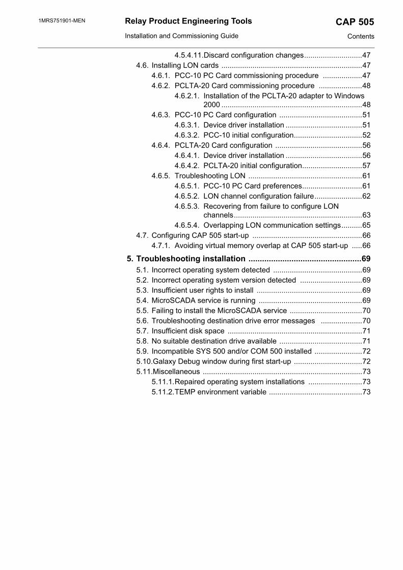
3.3.2.9. InstallingOnce you have clicked the Start button on the Select dialog, the progress of the installation is displayed in a dialog shown in Figure 3.3.2.9.-1.
25
1MRS751901-MENRelay Product Engineering ToolsCAP 5053. Installation Installation and Commissioning Guide
Fig. 3.3.2.9.-1 The Installing dialog
You may cancel the installation by clicking Cancel.
No support for a roll-back or uninstall is available, meaning that you cannot revert to the configuration that existed prior to the installation of CAP 505.
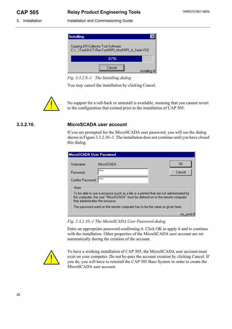
3.3.2.10. MicroSCADA user accountIf you are prompted for the MicroSCADA user password, you will see the dialog shown in Figure 3.3.2.10.-1. The installation does not continue until you have closed this dialog.
Fig. 3.3.2.10.-1 The MicroSCADA User Password dialog
Enter an appropriate password confirming it. Click OK to apply it and to continue with the installation. Other properties of the MicroSCADA user account are set automatically during the creation of the account.
To have a working installation of CAP 505, the MicroSCADA user account must exist on your computer. Do not by-pass the account creation by clicking Cancel. If you do, you will have to reinstall the CAP 505 Base System in order to create the MicroSCADA user account.
26

1MRS751901-MEN CAP 505Relay Product Engineering Tools
Installation and Commissioning Guide 3. Installation
3
If other products, which also utilize the MicroSCADA user account, have already been installed on your computer, use the same password that has been used before for the account.
The note text on the dialog incorrectly states that the MicroSCADA user account is used for accessing non-local printer resources. In CAP 505, you access non-local printer resources in the logged-on user's security context.
3.3.2.11. MicroSCADA Service Access Manager
Overview
If you install the Base System, the MicroSCADA Service Access Manager dialog, (shown in Figure 3.3.2.11.-1), appears on the screen. The installation does not continue until you have closed this dialog. The installation adds an icon for this tool to the CAP 505 program folder, so you can use it any time after the installation. However, usage of this tool requires that you have logged on to the operating system with administrator rights.
Purpose
By using the MicroSCADA Service Access Manager you can define those user-defined user groups whose members are allowed to start and stop the MicroSCADA service, i.e. start and stop the CAP 505 on the computer. In addition to the user-defined user groups, the built-in Users group can also be granted these rights. By default, all users belonging to the operating system’s Administrators group are granted these rights, and therefore, the tool never displays the Administrators group. If the users of CAP 505 on the computer will not be members of the Administrators group, you should use this tool to set up a proper configuration by granting the appropriate user groups the rights to start and stop the MicroSCADA service.
Fig. 3.3.2.11.-1 The MicroSCADA Service Access Manager dialog
27

1MRS751901-MENRelay Product Engineering ToolsCAP 5053. Installation Installation and Commissioning Guide
Granting the rights to a group
To grant the rights to start and stop the MicroSCADA service to the appropriate user groups, first highlight the group in the upper list labelled ‘No service start access’ and click Add. In the above figure, the user group Standard Corporate Users has been granted these rights.
Revoking the rights from a group
To revoke the rights from a user group, first highlight the group in the lower list labelled 'Service start access' and click Remove. In the above figure, the operating system’s built-in user group named Users has been revoked these rights.
This is a system-wide configuration, which affects also all the other products using the same kernel software. For example, if you have SYS 500 installed on the computer and you grant the rights to an imaginary group named Visitors (intended for ordinary visitors), any logged on member of that group is able to start and stop both CAP 505 and SYS 500 on the computer.
Saving the configuration
To save the configuration, click Close. Confirm that action by clicking OK on the dialog shown in Figure 3.3.2.11.-2.
Fig. 3.3.2.11.-2 Confirm to save the service access configuration
Discarding changes to the configuration
To close the tool without saving the configuration, click Cancel in the MicroSCADA Service Access Manager dialog. Provided that the configuration has been changed, you must confirm the cancellation by clicking OK on the dialog shown in Figure 3.3.2.11.-3. Otherwise click Cancel to return to the Service Access Manager.
Fig. 3.3.2.11.-3 Confirm to discard the changes to the service access configuration
28

1MRS751901-MEN CAP 505Relay Product Engineering Tools
Installation and Commissioning Guide 3. Installation
3
3.3.2.12. Installation completedAfter the selected software has fully been transferred onto your system, the CAP 505 installation displays the following message to inform you that the installation has been completed.
Fig. 3.3.2.12.-1 Notification that the installation has been completed successfully
Click OK to acknowledge the message.
3.3.2.13. System rebootIf some of the installed files were in use at the time of the installation, you are prompted to reboot your computer (see Figure 3.3.2.13.-1).
Fig. 3.3.2.13.-1 Request to reboot the computer
Click OK to reboot your computer immediately. You may reboot later if you wish, by clicking Cancel. However, notice that before starting CAP 505, you must reboot the computer in order for all of the changes to take effect in the system.
3.3.3. Cancelling the installationWhen you are about to cancel the installation, the dialog shown in Figure 3.3.3.-1 appears on the screen.
29

1MRS751901-MENRelay Product Engineering ToolsCAP 5053. Installation Installation and Commissioning Guide
Fig. 3.3.3.-1 Confirmation to cancel the installation
Click Exit Setup to exit the installation. Otherwise click Resume to continue the installation from where it was interrupted.
3.4. CAP 505 program folderThe program folder for CAP 505 is named as CAP 505 and it is accessible to all logged on users. The folder contains the items shown in Figure 3.4.-1.
Fig. 3.4.-1 CAP 505 program folder
• To start CAP 505, double-click the icon Start CAP 505.• To view the CAP 505 Release Notes, double-click the icon CAP 505 Release
Notes.
The three subfolders are explained below.
3.4.1. Subfolder - Doc• To view a manual, double-click the appropriate icon entry.
Note! This operation requires that a viewer capable of reading PDF files is installed. Figure 3.4.1.-1 shows different manuals in the Doc subfolder.
30

1MRS751901-MEN CAP 505Relay Product Engineering Tools
Installation and Commissioning Guide 3. Installation
3
Fig. 3.4.1.-1 Subfolder - Doc
3.4.2. Subfolder - Setup
Fig. 3.4.2.-1 Subfolder - Setup
• To install the Adobe Acrobat Reader, close any programs you have running • Double-click the icon Install Adobe Acrobat Reader
31

1MRS751901-MENRelay Product Engineering ToolsCAP 5053. Installation Installation and Commissioning Guide
3.4.3. Subfolder - Tools
Fig. 3.4.3.-1 Subfolder - Tools
• To start the MicroSCADA Service Access Manager tool, double-click the icon MicroSCADA Service Access Manager.
• To start the SPA Terminal Emulator, double-click on its icon.
(For more information about the SPA Terminal Emulator, please see the Tools for Relays and Terminals manual).
3.4.4. Shortcut to the CAP 505 program folderA shortcut named CAP 505 has been added onto your desktop, see Figure 3.4.4.-1. This shortcut provides access to the CAP 505 program folder from your desktop.
Fig. 3.4.4.-1 The shortcut to the program folder on your desktop
• To open the CAP 505 program folder, double-click the shortcut.
3.5. Uninstalling the softwareUninstalling the CAP 505 software is not currently supported.
32

1MRS751901-MEN CAP 505Relay Product Engineering Tools
Installation and Commissioning Guide 4. Commissioning
4
4. Commissioning
This chapter describes the commissioning activities after software installation.
4.1. OverviewCommissioning the installed software involves the following tasks:
• Applying the license information for CAP 505. Whenever the CAP 505 Base System has been installed, this task must be performed. Without proper license information, CAP 505 will not execute. You apply the license information using the License tool, see Section “License tool” on page 36.
• Preparing the computer for LON®1 communication. This comprises installation and configuration of LON communication card(s) and accompanying device drivers, if not done previously. This you accomplish by means of the System Configuration Tool, see Section “System Configuration Tool” on page 38.
• Optionally, configuring the operating system’s user groups whose members are granted the rights to start and stop the MicroSCADA service on your computer. You grant these rights using the MicroSCADA Service Access Manager tool, see Section “MicroSCADA Service Access Manager” on page 27.
4.2. Communication support
4.2.1. ProtocolsSupported communication protocols are:
• SPA• LON
For information on which communication protocols are applicable to various relay terminals, refer to the Tools for Relays and Terminals manual.
4.2.2. ChannelsCAP 505 allows you to define the total of eight (8) communication channels in a system configuration. Each defined serial port using SPA protocol and each LON card channel occupies one communication channel. For example, a PCLTA-20 card reserves one communication channel allowing you to define seven serial ports with the SPA protocol.
1. LON is a registered trademark of Echelon Corporation.
33

1MRS751901-MENRelay Product Engineering ToolsCAP 5054. Commissioning Installation and Commissioning Guide
4.2.3. Serial port communication
4.2.3.1. CAP 505 vs. operating system’s serial port configurationGeneralEach serial port defined for use in CAP 505 must also exist at the operating system level. For example, if you define serial ports COM1 through COM4 in CAP 505, you must also define them under the operating system.
Regarding the computer's serial port communication capabilities, it is recommended to verify that the serial ports are correctly configured and working at the operating system level.
For detailed information on configuring the serial ports under the operating system, refer to the operating system Help or other applicable source of information.
Advanced serial port settingsAdvanced serial port settings are defined only at the operating system level. Therefore, you do not have to define them in CAP 505. These settings include:
• interrupt request line (IRQ)• input/output (I/O) addresses• data buffering settings
Basic serial port settingsThe basic serial port settings that are defined at the operating system level are overridden by the settings you specify in CAP 505. These settings include:
• baud rate• data bits• parity • stop bits
4.2.3.2. Using USB portsIn order to utilize a USB port with CAP 505, you need to use a USB to serial adapter. You also need to install the driver software for it (this software is distributed by the adapter). The adapter can be set to a serial port in the range within COM 1 to COM 8. You need to check your operating system setup for a free COM-port.
In the CAP 505 system configuration setting of serial port you select the serial port you have assigned to be provided by the converter. No further settings are required in CAP 505 for using a USB port since the USB looks to a serial adapter like a genuine serial port to CAP 505. USB ports are applicable in Windows 2000, not in Windows NT
34

1MRS751901-MEN CAP 505Relay Product Engineering Tools
Installation and Commissioning Guide 4. Commissioning
4
4.2.4. LON communication
4.2.4.1. LON communication adapters
The PCLTA-10 PC LonTalk Adapter is not supported. RER 109 PCLTA card is also no longer available. It is supported only on the Windows NT operating system.
4.2.4.2. LON communication software components
4.3. Commissioning communication componentsGenerally, commissioning the communication components comprises the following procedures:
1. Install the LON communication card(s) into your computer.2. Install the device driver for the LON communication card(s).3. Configure the device driver for the LON communication card(s).4. If necessary, configure the Neuron Chip on the LON communication card(s).5. Verify that the computer's serial ports are working correctly.
The main tool for accomplishing these tasks is the CAP 505 System Configuration Tool, see Section “System Configuration Tool” on page 38.
Table 4.2.4.1-1 LON adapter support
Adapter Type Device driver Remarks
PCLTA-20PCI LonTalk Adapter
PCI half-length bus card
PNPLON CAP 505 supports up to 4 PCLTA-20 cards in the system at the time.Supports Plug-and-Play and downloadable memory.
PCC-10PC Card
A Type II PC card,formerly PCMCIA
PNPLON Only a single card can be present in the system at a time, due to the operating system Type II PC Card support capabilities.Supports Plug-and-Play and downloadable memory.
Table 4.2.4.2-1 Software components for LON communication
Item RemarksMiSCLONPdevice driver
The device driver for the old RER 109 PCLTA Card. Supplied with an installation and a configuration tool (only for Windows NT system).
PNPLONdevice driver
The device driver for the PCC-10 and PCLTA 20 Cards.Supplied as a third-party (Echelon) installation and configuration package.
Net Interface Tool For initial configuration of the Neuron®a Chip(s) on the RER 109 PCLTA Cards.
a. Neuron is a registered trademark of Echelon Corporation.
35

1MRS751901-MENRelay Product Engineering ToolsCAP 5054. Commissioning Installation and Commissioning Guide
4.4. License tool
4.4.1. GeneralThe License tool is intended for applying the license information. CAP 505 does not provide any specific entry for accessing the License tool, instead the tool appears automatically at CAP 505 start-up, if the computer does not contain a valid license.
4.4.2. License Information dialogThe License Information dialog is illustrated in Figure 4.4.2.-1. It is initially displayed when the license information cannot be found or is otherwise invalid.
Fig. 4.4.2.-1 License Information dialog
4.4.3. Entering license InformationCAP 505 delivery contains the license information printed on the license label, which you find on the cover of the CAP 505 Program CD. Be sure to store the information, so that it is available in case you need to re-enter the license information.
When you enter the requested items, be careful to type the text exactly as provided on the license label. All the fields are case-sensitive and space characters are also taken into account.
Table 4.4.2-1 Dialog itemsCustomer field For entering the value for the Customer.System ID field For entering the value for the System ID.Authorization key field For entering the value for the Authorization key.OK button For saving the license information and closing the License tool,
see Section “Entering license Information” on page 36.Apply button For saving the information without closing the License tool, see
Section “Entering license Information” on page 36.Close button For closing the License tool.
36

1MRS751901-MEN CAP 505Relay Product Engineering Tools
Installation and Commissioning Guide 4. Commissioning
4
After you have entered all the items, apply the information. Thereafter, you must restart CAP 505 in order for the new license to take effect.
To enter the license information:
1. Enter the Customer name into the Customer field.2. Enter the System ID value into the System ID field.3. Enter the Authorization key value into the Authorization key field.4. Click OK or Apply, if you do not want to close the dialog immediately. If the
supplied information is correct, you will see one of the messages shown below:
Fig. 4.4.3.-1 License information added successfully
Fig. 4.4.3.-2 License information updated successfully
Dismiss the message by clicking OK. When you close the dialog, you will be further notified with the message shown in Figure 4.4.3.-3.
Fig. 4.4.3.-3 Restart required
As stated in the message, you have to restart CAP 505.
4.4.4. Invalid license informationIf you have supplied incorrect information, the tool displays the message shown in Figure 4.4.4.-1.
37

1MRS751901-MENRelay Product Engineering ToolsCAP 5054. Commissioning Installation and Commissioning Guide
Fig. 4.4.4.-1 Incorrect license information could not be saved
Click OK to dismiss the message and correct the license information carefully.
An example of a correctly entered license information is provided in Figure 4.4.4.-2.
Fig. 4.4.4.-2 An example of license information
4.5. System Configuration Tool
4.5.1. GeneralThe System Configuration Tool is intended for setting up the system configuration, which is required to enable communication with the relays in CAP 505. Every project has its own copy of the system configuration, which is enforced when the project is opened into the Project Structure Navigator. Likewise, when a project is closed, its system configuration is stored with the project.
Some of the System Configuration Tool functions, such as modifying LON device driver settings, require administrator rights at the operating system level.
38

1MRS751901-MEN CAP 505Relay Product Engineering Tools
Installation and Commissioning Guide 4. Commissioning
4
4.5.2. Target projectThe System Configuration Tool automatically edits the system configuration of the project that is being opened into the Project Structure Navigator. If there is no project open in the Project Structure Navigator, the System Configuration Tool will not execute.
4.5.3. StartingTo access this tool, two entry points are provided:
• System Tools menu in the Project Structure Navigator• the Communication page of the General Object Attributes dialog
4.5.4. System Configuration Tool dialog The System Configuration Tool dialog is shown in Figure 4.5.4.-1.
Fig. 4.5.4.-1 System Configuration Tool dialog
The Communication page contains two pages:
• Serial Ports • LON
Table 4.5.4-1 System Configuration Tool items
Communication configuration pagesSerial Ports For managing serial port configuration, see Section “Serial Ports page” on
page 40.
39

1MRS751901-MENRelay Product Engineering ToolsCAP 5054. Commissioning Installation and Commissioning Guide
4.5.4.1. Serial Ports pageThe Serial Ports page of the System Configuration Tool is shown in Figure 4.5.4.1.-1. Initially the configuration is empty, as illustrated.
Fig. 4.5.4.1.-1 The Serial Ports page
LON For managing the LON configuration, see Section “LON page” on page 43.
Common dialog buttonsOK For closing the System Configuration Tool and saving the configuration, see
Section “Save configuration - close tool” on page 46Cancel For closing the System Configuration Tool without saving the configuration,
see Section “Discard configuration changes” on page 47.Apply For saving the configuration without closing the System Configuration Tool,
see Section “Save configuration - proceed configuration” on page 47.
Table 4.5.4-1 System Configuration Tool items
Table 4.5.4.1-1 Serial Ports page itemsSerial Ports List for selecting a serial port. Displays all the currently defined
serial ports.Protocol List for assigning the communication protocol to the currently
selected serial port.Connection Type This list is not used in CAP 505 and is always disabled.Modem Command (AT) This field is not used in CAP 505 and is always disabled.Baud Rate List for assigning the baud rate to the currently selected serial
port.
40

1MRS751901-MEN CAP 505Relay Product Engineering Tools
Installation and Commissioning Guide 4. Commissioning
4
4.5.4.2. Serial ports - Adding To add a serial port:
Click Add … to bring up the dialog shown in Figure 4.5.4.2.-1.
1. Enter the serial port number, which must be in range of 1 through 8. If you enter an out-of-range value, or a value which is already in use, you are requested to enter a proper value.
Fig. 4.5.4.2.-1 Define the port number for the new COM port
2. Click OK to add the new serial port, which appears on the Serial Ports list (see Figure 4.5.4.2.-2). Otherwise, click Cancel to keep the configuration unchanged.
Data Bits List for assigning the data bits setting to the currently selected serial port.
Parity List for assigning the parity setting to the currently selected serial port.
Stop Bits List for assigning the stop bits setting to the currently selected serial port.
Add … button For adding a new serial port, see Section “Serial ports - Adding” on page 41.
Delete … button For deleting the currently selected serial port, see Section “Serial ports - Deleting” on page 42.
Table 4.5.4.1-1 Serial Ports page items
41

1MRS751901-MENRelay Product Engineering ToolsCAP 5054. Commissioning Installation and Commissioning Guide
Fig. 4.5.4.2.-2 A new serial port COM1 added with default values
Certain default values are assigned to the newly added port's basic settings and communication protocol. If you wish to use other than the default values, you can configure them as described below.
4.5.4.3. Serial ports - ConfiguringThe following table displays serial port properties, which you can configure on a per-port basis.
To configure a serial port property:
1. Select the serial port from the Serial ports list.2. Configure the item by selecting the desired value from the appropriate list.
4.5.4.4. Serial ports - Deleting Any serial port, defined in a project's system configuration, can be deleted at any time.
To delete a serial port from the configuration:
1. Select the serial port from the Serial Ports list.
Table 4.5.4.3-1 Configurable serial port properties
Property Available valuesCommunication protocol SPABaud Rate 300, 600, 1200, 2400, 4800, 9600, 19200Data Bits 5, 6, 7, 8Parity None, Odd, EvenStop Bits 1, 2
42

1MRS751901-MEN CAP 505Relay Product Engineering Tools
Installation and Commissioning Guide 4. Commissioning
4
2. Click Delete ….3. When prompted to confirm the deletion, click Yes to delete the serial port (see
Figure 4.5.4.4.-1). Otherwise click No to leave the serial port intact.
Fig. 4.5.4.4.-1 Confirm to delete the selected serial port
The deletion invalidates the communication settings of any device objects which have been configured to use the port you are about delete.
If you accidentally delete ports, you can revert to the most recently saved system configuration by clicking Cancel (see Section “Discard configuration changes” on page 47).
4.5.4.5. LON pageThe LON page of the System Configuration Tool is shown in its initial state in Figure 4.5.4.5.-1.
43

1MRS751901-MENRelay Product Engineering ToolsCAP 5054. Commissioning Installation and Commissioning Guide
Fig. 4.5.4.5.-1 The LON page
4.5.4.6. Selecting the adapterThe System Configuration Tool allows you to use only a single type of a LON card at a time, i.e. you cannot have multiple types of LON cards in-use simultaneously. The LON card is selected from the Adapter type list. If you do not use any LON cards, select the option No card from the list.
When you select an adapter from the Adapter type list, the tool scans the computer for currently defined LON devices for the selected adapter type. If such are found, they will be displayed immediately, allowing you to take the channel(s) into use by assigning the appropriate channel settings (see Section “Assigning Subnet/Node settings” on page 45).
Table 4.5.4.5-1 LON page itemsAdapter type For selecting the adapter type. Displays all the supported adapters.Card For assigning the Subnet and Node values to the LON channels.Install Driver… button
For installing/configuring the driver for the currently selected adapter.Note! Driver installation and some of the configuration functions require that you have logged on with Administrator Rights.
Configure Channel… button
For initiating the initial configuration of the currently selected channel and for enforcing modified Subnet/Node values to the currently selected channel.
Delete Channel...button
For deleting the currently selected channel.
44

1MRS751901-MEN CAP 505Relay Product Engineering Tools
Installation and Commissioning Guide 4. Commissioning
4
If no LON devices have been defined or you want to modify the current configuration by e.g. adding new devices or removing currently defined devices, click the Install Driver button. For RER 109 PCLTA cards this invokes the MicroSCADA Device Driver Configuration tool. For other types of cards, this invokes the application which installs the device driver onto your computer.
4.5.4.7. Assigning Subnet/Node settingsEach LON channel needs to have a unique Subnet/Node value pair assigned to it, since it appears as any other node on the network. Valid range is 1 through 127, inclusive for both the Subnet and Node.
To assign the Subnet/Node values to a LON channel:
1. Click on the intended channel's Subnet cell with the mouse to activate it (see Figure 4.5.4.7.-1).
Fig. 4.5.4.7.-1 Subnet cell of channel A is activated
2. Type in the appropriate value for the Subnet.3. Repeat the procedure for the Node cell.
When you edit these values, the device name of the edited channel begins to flash, reminding you that the edited values have yet to be written to the respective card. To have the values written to the card, select the channel and press the Configure Channel... button. Upon pressing the button, the System Configuration Tool functions are according to the type of the currently selected adapter as follows:
.
45

1MRS751901-MENRelay Product Engineering ToolsCAP 5054. Commissioning Installation and Commissioning Guide
PCC-10 PC card/PCLTA-20 card
If you have not done the initial configuration for the selected channel, then configure it by means of the LonWorks® Plug’n Play control panel, as explained in Sections “PCC-10 initial configuration” on page 52 or “PCLTA-20 initial configuration” on page 57. In case you are just applying modified Subnet/Node values, just close the LonWorks® Plug’n Play control pane when it appears.
Fig. 4.5.4.7.-2 The LonWorks® Plug’n Play control panel opened for a PCLTA-20 card
Finally, save the system configuration as explained below.
4.5.4.8. Saving system configuration The system configuration is saved permanently by using either the OK or the Apply button. The difference is, that the OK button closes the System Configuration Tool, whereas the Apply button allows you to proceed working with the tool.
The tool also provides you with the possibility to revert to the most recently saved configuration to prevent accidental changes to the configuration, (see Section “Discard configuration changes” on page 47).
4.5.4.9. Save configuration - close toolTo save a changed configuration, closing the System Configuration Tool, click OK. The System Configuration Tool prompts you to confirm the operation (see Figure 4.5.4.9.-1).
46

1MRS751901-MEN CAP 505Relay Product Engineering Tools
Installation and Commissioning Guide 4. Commissioning
4
Fig. 4.5.4.9.-1 Confirm to save the configuration
To save the configuration click Yes. Clicking No enforces the most recently saved configuration.
4.5.4.10. Save configuration - proceed configurationTo save a changed configuration without closing the System Configuration Tool, click Apply. The System Configuration Tool prompts you to confirm the operation (see Figure 4.5.4.10.-1).
Fig. 4.5.4.10.-1 Confirm to save the configuration
To save the configuration, click Yes and the configuration becomes the most recently saved configuration. Otherwise click No to proceed without saving.
4.5.4.11. Discard configuration changesTo revert to the most recently saved configuration, click Cancel. This closes the System Configuration Tool without further notifications.
4.6. Installing LON cards
4.6.1. PCC-10 PC Card commissioning procedureThe PCC-10 PC Card communications hardware and software are configured in the following order:
1. Install the card into the PC (see Section “PCC-10 PC Card configuration” on page 51).
2. Install and configure the PCC-10 PC Card device driver (PNPLON), (see Sections “Device driver installation” on page 51 and “PCC-10 initial configuration” on page 52).
47

1MRS751901-MENRelay Product Engineering ToolsCAP 5054. Commissioning Installation and Commissioning Guide
4.6.2. PCLTA-20 Card commissioning procedureThe PCLTA-20 Card communications hardware and software are configured in the following order:
1. Install the card into the PC (see Section “PCLTA-20 Card configuration” on page 56).
2. Install and configure the PCLTA-20 Card device driver (PNPLON), (see Sections “Device driver installation” on page 56 and “PCLTA-20 initial configuration” on page 57).
4.6.2.1. Installation of the PCLTA-20 adapter to Windows 2000 Software installation
When drivers are installed to a Windows 2000 Server where Terminal Services are running, it should be done using the Add/Remove Programs under the Control Panel. Browse the path where the Driver installation file exists. If the operating system is Windows 2000 Professional, you can run the self-extracting installation exe-file directly.
1. Launch the PCLTA-20 software installation program. Choose Setup Figure 4.6.2.1.-1.
Fig. 4.6.2.1.-1 Dialog for launching the PCLTA-20 software installation
2. Follow the instructions on the screen Figure 4.6.2.1.-2.
48

1MRS751901-MEN CAP 505Relay Product Engineering Tools
Installation and Commissioning Guide 4. Commissioning
4
Fig. 4.6.2.1.-2 The welcome dialog of the PCLTA-20 Setup program
3. By default, the installation directory is c:\Lonworks. The path may be modified by using the “Browse” button Figure 4.6.2.1.-3.
Fig. 4.6.2.1.-3 The dialog shows the default installation directory
49

1MRS751901-MENRelay Product Engineering ToolsCAP 5054. Commissioning Installation and Commissioning Guide
4. At the end of the installation, select the restart option.
PCLTA - 20 Card installation
1. Turn off the PC and remove the power cord. 2. Open the PC case and locate an empty 32-bit PCI slot. 3. Check that RER107 LON Communication Adapter is attached to the PCLTA-20
adapter. 4. Insert the PCLTA-20 adapter into the slot. 5. Reinsert the power cord and then restart the PC.
A “New Hardware Found” window will be displayed briefly, when the operating system recognizes the PCLTA-20 adapter. You can check if installation has been successful by using the Control Panel/ Administrative Tool/Computer Management/ Device Manager.
Configuration settings for PCLTA – 20 adapter
Open the Control panel by selecting the “LonWorks Plug ’n Play” icon in the Control Panel Figure 4.6.2.1.-4 and Table 4.6.2.1-1).
Fig. 4.6.2.1.-4 The PCLTA Control Panel
Table 4.6.2.1-1 Description of the PCLTA Control Panel dialog itemsDevice Selected Controls which PCLTA-20 adapter is
selected for configuration.
50

1MRS751901-MEN CAP 505Relay Product Engineering Tools
Installation and Commissioning Guide 4. Commissioning
4
Upon clicking the Transceiver... button, Figure 4.6.2.1.-5 will appear on the screen.
Fig. 4.6.2.1.-5 The Transceiver Control Panel
The chosen options have to be according to the ones presented in the dialog. Click the Apply button to enable the driver to utilize the chosen features.
4.6.3. PCC-10 PC Card configuration
4.6.3.1. Device driver installationThe installer for the PCC-10 PC Card device driver is started by clicking the Install Driver… button, located on the LON page of the System Configuration Tool (see Figure 4.6.3.1.-1).
NI Application Controls the type of image or application to be used. Image should be set to PCC10L7.
Automatic Flush Cancel Should be checked.
Transceiver Opens the PCLTA-20 Transceiver dialog. Settings should be according to Figure 4.6.4.4.-11.
System Image Path Specifies the full directory path for the PCLTA-20 system images. This path is set by the PCLTA-20 Installation software but may be modified by the user.
Table 4.6.2.1-1 Description of the PCLTA Control Panel dialog items
51

1MRS751901-MENRelay Product Engineering ToolsCAP 5054. Commissioning Installation and Commissioning Guide
Fig. 4.6.3.1.-1 Starting the driver installation for the PCC-10 PC Card
The program, which you start, installs images and the driver (PNPLON.SYS) for the PCC-10, PCLTA-10 and PCLTA-20 cards.
Selecting the destination directory
By default, the destination directory is be C:\LONWORKS. If you decide to install to another directory, you have to manually specify the directory path to the installed system image later.
Selecting the numeric base for LonWorks devices
During the driver installation you will be prompted to supply the numeric base for all the LonWorks Plug’n Play devices. To be compatible with CAP 505, please use 1 as the numeric base, so the device name will be created as LON1.
After the driver installation, restart the computer and perform the initial device driver configuration as explained below.
4.6.3.2. PCC-10 initial configurationAfter you have installed the PCC-10 card and its device driver, and rebooted the computer, you have to verify that correct settings are to be used. Initialize also the
52

1MRS751901-MEN CAP 505Relay Product Engineering Tools
Installation and Commissioning Guide 4. Commissioning
4
node state of the card’s channel as configured. This means that the following tasks have to be done:
• Select the correct type of transceiver. The default setting FT-10 has to be changed to Custom with appropriate data.
• Select the correct type of the network interface application (NI Application). By default, the device driver installation program configures the NSIPCC as the NI Application. However, NSIPCC has to be changed to PCC10L7.
• Initialize the card to the configured node state, along with the initial Subnet/Node settings.
To configure:
1. Start CAP 505 and enter the LON page of the System Configuration Tool.2. If not selected, select the PCC-10 card as the type of the adapter. By this time, a
LON channel should be available on the System Configuration Tool. If there are none, then the device driver has failed to start and needs to be re-configured. See Section “PCC-10 PC Card preferences” on page 61.
3. Enter values for the Subnet and Node, and press the Configure Channel... button to open the LonWorks® Plug’n Play control panel.
Selecting the network interface application4. First, select the PCC10L7 network interface application, as shown below.
Fig. 4.6.3.2.-1 Selecting the correct NI Application
5. Check the Automatic Flush Cancel option as in the figure above.6. Click Apply to apply the selections.
53

1MRS751901-MENRelay Product Engineering ToolsCAP 5054. Commissioning Installation and Commissioning Guide
Selecting the type of the transceiver7. Click the Transceiver... button to open the dialog shown below.
Fig. 4.6.3.2.-2 Switching from the default transceiver setting to the Custom transceiver
8. From the Transceiver list, select the Custom option.9. Select Single Ended as the type of the transceiver.10.Set the Bit rate to 1250 Kb.11. For Raw data - Layer 1 timing, ensure that the data presented in the above
dialog is used.12.For Raw data - Xcvr params, ensure that the data presented in the above dialog
is used.13.Click OK to save the configuration closing the Transceiver dialog. Next,
initialize the card to the configured state as explained below.
Initializing the node state to be configured
14.On the LonWorks® Plug’n Play control panel Figure 4.6.3.2.-1 above), click the Diagnostics... button to open the Diagnostics dialog shown below.
54

1MRS751901-MEN CAP 505Relay Product Engineering Tools
Installation and Commissioning Guide 4. Commissioning
4
Fig. 4.6.3.2.-3 Some basic diagnostics information available indicating that the device driver has been started and can be configured
15.Initialize the node state to configured by clicking Reset.16.Verify the initialization by clicking Test. Observe that the Node State is reported
to be Configured as in the figure below.
Fig. 4.6.3.2.-4 Results of the Test function, the state is now configured
17.At this stage the card is ready for use. Click OK to close the dialog. Close also the LonWorks® Plug’n Play control panel by clicking OK on it and continue your work with the System Configuration Tool.
55

1MRS751901-MENRelay Product Engineering ToolsCAP 5054. Commissioning Installation and Commissioning Guide
For additional information on configuring the PCC-10 device driver, you may want to view the Windows Help shipped with the device driver package. See also Section “PCC-10 PC Card preferences” on page 61.
To access the Help, open the operating system’s Control Panel and open the applet titled LonWorks® Plug’n Play (see Figure 4.6.3.2.-5).
Fig. 4.6.3.2.-5 Starting the LonWorks® Plug’n Play control panel
Once the LonWorks® Plug’n Play control panel is running, click Help to view the Help for the package.
4.6.4. PCLTA-20 Card configuration
4.6.4.1. Device driver installationThe installer for the PCLTA-20 Card device driver is started by clicking the Install Driver… button, located on the LON page of the System Configuration Tool (see Figure 4.6.4.1.-1).
56

1MRS751901-MEN CAP 505Relay Product Engineering Tools
Installation and Commissioning Guide 4. Commissioning
4
Fig. 4.6.4.1.-1 Starting the driver installation for the PCLTA-20 Card
The program, which you start, installs images and the driver (PNPLON.SYS) for the PCC-10, PCLTA-10 and PCLTA-20 cards.
Selecting the destination directory
By default, the destination directory is be C:\LONWORKS. If you decide to install to another directory, you have to manually specify the directory path to the installed system image later.
Selecting the numeric base for LonWorks devices
During the driver installation you will be prompted to supply the numeric base for all the LonWorks Plug’n Play devices. To be compatible with CAP 505, please use 1 as the numeric base, so the first device name will be created as LON1, the second as LON2 and so on.
After the driver installation, close CAP 505 prior to restarting the computer and perform the initial configuration as explained below.
4.6.4.2. PCLTA-20 initial configurationAfter you have installed the PCLTA-20 card(s) and its device driver, and rebooted the computer, you have to verify that correct settings are to be used. Configure also
57

1MRS751901-MENRelay Product Engineering ToolsCAP 5054. Commissioning Installation and Commissioning Guide
the node state of each of the channels as configured. This means that the following tasks have to be done:
• Ensure that the correct type of transceiver is used for each channel.• Ensure that the correct type of the network interface application (NI Application)
is used for each channel.• Initialize the card to the configured node state along with initial Subnet/Node
settings.
To configure:
1. Start CAP 505 and enter the LON page of the System Configuration Tool.2. If not selected, select the PCLTA-20 card as the type of the adapter. By this time,
the System Configuration Tool should have as many LON channels as there are PCLTA-20 cards in the computer. If there are not, most probably the operating system has failed to provide the card with sufficient/suitable IRQ and I/O resources. Try to free some resources and reboot the computer.
3. For each LON channel, enter values for the Subnet and Node, and press the Configure Channel... button to open the LonWorks® Plug’n Play control panel.
Selecting the device name4. First, ensure that the selected device matches the device name of the channel
you selected in the System Configuration Tool (see Figure 4.6.4.2.-1 below).
Fig. 4.6.4.2.-1 Device name LON1 is selected both in the System Configuration Tool and in the LonWorks control panel.
Selecting the network interface application
5. Select the PCC10L7 Application, as shown below.
58

1MRS751901-MEN CAP 505Relay Product Engineering Tools
Installation and Commissioning Guide 4. Commissioning
4
Fig. 4.6.4.2.-2 Selecting the correct NI Application
6. Check the Automatic Flush Cancel option as in the figure above.7. Click Apply to apply the selections.
Selecting the type of the transceiver8. Click the Transceiver... button to open the dialog shown below.
Fig. 4.6.4.2.-3 Switching from the default transceiver setting to the Custom transceiver
59

1MRS751901-MENRelay Product Engineering ToolsCAP 5054. Commissioning Installation and Commissioning Guide
9. From the Transceiver list, select the option Custom.10.Select Single Ended as the type of the transceiver.11.Set the Bit rate to 1250 Kb.12.For Raw data - Layer 1 timing, ensure that the data presented in the above
dialog is used.13.For Raw data - Xcvr params, ensure that the data presented in the above dialog
is used.14.Click OK to save the configuration closing the Transceiver dialog. Next,
initialize the card to the configured state as explained below.
Initializing the node state to configured
15.On the LonWorks® Plug’n Play control panel Figure 4.6.4.2.-2 above), click the Diagnostics... button to open the Diagnostics dialog shown below.
Fig. 4.6.4.2.-4 Some basic diagnostics information available indicating that the device driver has been started and can be configured
16.Initialize the node state to configured by clicking Reset.17.Verify the initialization by clicking Test. Observe that the Node State is reported
to be Configured as in Figure 4.6.4.2.-5 below.
60

1MRS751901-MEN CAP 505Relay Product Engineering Tools
Installation and Commissioning Guide 4. Commissioning
4
Fig. 4.6.4.2.-5 Results of the Test function, the state is now configured
18.At this stage the card is ready for use. Click OK to close the dialog. Close also the LonWorks® Plug’n Play control panel by clicking OK on it and continue your work with the System Configuration Tool.
For additional information on configuring the PCLTA-20 device driver, you may want to view the Windows Help shipped with the device driver package.
To access Help, open the operating system’s Control Panel and open the applet titled LonWorks® Plug’n Play (shown in Figure 4.6.4.2.-6).
Fig. 4.6.4.2.-6 Starting the LonWorks® Plug’n Play control panel
Once the LonWorks® Plug’n Play control panel is running, click Help to view the Help for the package.
4.6.5. Troubleshooting LON
4.6.5.1. PCC-10 PC Card preferencesIt may be necessary to configure the preferences of the PCC-10 card’s device driver, if you are unable to configure the card to the configured state. In such a case, open the Preferences page of the LonWorks® Plug’n Play control panel and try another IRQ and/or I/O range setting for the card (see Figure 4.6.5.1.-1 below). You can modify the current settings by means of the up/down buttons in the dialog (see the cursor in the figure).
61

1MRS751901-MENRelay Product Engineering ToolsCAP 5054. Commissioning Installation and Commissioning Guide
Fig. 4.6.5.1.-1 PCC-10 preferences
The default IRQ setting is automatic. However, in Windows it may happen that the automatic IRQ assignment results in a non-working configuration even if the assigned IRQ appears to be free for use. You can use e.g. the operating system’s diagnostics application (WINMSD.EXE) to determine the IRQs that are free and try to manually set a new IRQ for the PCC-10 card. In the figure above, IRQ 9 has been set for the card. The new setting will take effect on the next computer reboot.
4.6.5.2. LON channel configuration failureFigure 4.6.5.2.-1 shows the error message, which may appear upon pressing the Configure Channel... button in computers having the Lon Network Tool (LNT 505) installed. In this case, dismiss the message by clicking OK. Do the corrective measures explained in Section “Recovering from failure to configure LON channels” on page 63 and retry the channel configuration.
Fig. 4.6.5.2.-1 Failure in card initialization
62

1MRS751901-MEN CAP 505Relay Product Engineering Tools
Installation and Commissioning Guide 4. Commissioning
4
4.6.5.3. Recovering from failure to configure LON channelsThis section provides instructions to fix a situation where the usage of the Lon Network Tool (LNT 505) has prevented the channel configuration in CAP 505.
Both LNT 505 and CAP 505 use a common file NETTOOLS.INI. This file is located in the Windows directory of the computer, e.g. C:\WINNT. If you cannot find it there, you have to reinstall the CAP 505 Base System to get a working copy of the file.
LNT 505 may modify the values of the following NETTOOLS.INI keys, so that they cannot be read by the CAP 505 kernel:
• FTR• LOOKUP• OFFLINE
These keys can be found under the section STATUS Figure 4.6.5.3.-1.
63

1MRS751901-MENRelay Product Engineering ToolsCAP 5054. Commissioning Installation and Commissioning Guide
Fig. 4.6.5.3.-1 An example of the file NETTOOLS.INI. As the selection indicates, lengthy data has been written for the critical keys
The solution for the problem is to empty the values of the addressed keys, which is a safe operation to do.
To empty the values:
1. Preferably, exit LNT 505 if it is running.
64

1MRS751901-MEN CAP 505Relay Product Engineering Tools
Installation and Commissioning Guide 4. Commissioning
4
2. Open the file NETTOOLS.INI in any ASCII editor, for example Notepad (NOTEPAD.EXE).
3. Under the section STATUS, empty the values of the keys FTR, LOOKUP and OFFLINE as illustrated in Figure 4.6.5.3.-2 below.
Fig. 4.6.5.3.-2 An example of the file NETTOOLS.INI. As the selection indicates, the values have been removed
4. Save changes to the file and close the editor.5. Retry the channel configuration.
4.6.5.4. Overlapping LON communication settingsIn CAP 505, every object communicating over LON must be assigned a LON settings configuration that is unique within the project. The LON settings configuration comprises the following items:sz
• Card Number• Channel• Subnet Number• Node Number
65

1MRS751901-MENRelay Product Engineering ToolsCAP 5054. Commissioning Installation and Commissioning Guide
If you have specified a non-unique settings configuration, the following notification appears upon clicking OK on the Project Structure Navigator’s General Object Attributes dialog.
Fig. 4.6.5.4.-1 Overlapping LON settings have been specified. In this case the offending object is named ELG___R1
In such a case, you have to change one or more of the above presented four items to form a unique settings configuration within the project.
4.7. Configuring CAP 505 start-upThis section provides information on how to avoid possible CAP 505 start-up problems that may occur under some operating system configurations. Unless you are experiencing CAP 505 start-up problems, you can skip this section.
4.7.1. Avoiding virtual memory overlap at CAP 505 start-upThe MicroSCADA service of CAP 505 uses a hard-coded address for the address of the memory pool.
However, it is possible that in certain PC configurations, some other system component (e.g. a hardware driver) happens to map on an address within the pool. The MicroSCADA service start-up itself has a search mechanism to handle the address overlapping, but it has no chance to prevent other MicroSCADA processes or external programs from failing to map the memory pool. Consequently, CAP 505 does not start.
If this happens, an error message of the following format will be shown in the CAP 505 error log file \CAP505\SYS\ACTIVE\SYS_\SYS_ERROR.LOG and on the Notification Window (if open):Add the following line to sys_config.par and restart MicroSCADAMEMORY_POOL_HOLE = 30000000 - 301FFFFF
? Map_Global_Memory(MapViewOfFileEx): 487
Since the situation causes CAP 505 (e.g. PICA.EXE program) to crash, the computer must be restarted in order to take the corrective measures explained below.
As the remedy, the MEMORY_POOL_HOLE parameter must be activated in the file \CAP505\SYS\ACTIVE\SYS_\SYS_CONFIG.PAR. This parameter advises the MicroSCADA start-up code not to use the specified virtual memory area for the global memory pool.
To change the value, open the file SYS_CONFIG.PAR in a text editor (for example, NOTEPAD.EXE) and specify the memory pool hole copying the line containing
66

1MRS751901-MEN CAP 505Relay Product Engineering Tools
Installation and Commissioning Guide 4. Commissioning
4
parameter name MEMORY_POOL_HOLE exactly as shown in the message (note that the address range below is an example only, and the actual values to be used are always configuration dependent):MEMORY_POOL_HOLE = 30000000 - 301FFFFF
The possibly existing parameter MEMORY_POOL_ADDRES should not be touched. The configuration file may also contain several MEMORY_POOL_HOLE lines, because there is a slight possibility that even the second start-up fails now suggesting another range to be excluded.
Save your changes and exit the editor. Be careful not to make any inadvertent changes to the file! After the restart CAP 505 should be initialized without errors.
Below is an example of a modified SYS_CONFIG.PAR:; File: Sys_config.par; Description: Configuration for 'static' base system parameters; Leading ';' indicates commented line; Base system version 8.4.4;---------------------------------------------------------------------------;MEMORY_POOL_HOLE = 30000000 - 301FFFFF ;Excluded virtual memory area;MEMORY_POOL_SIZE = 20 ;Must be 4,8,12,16,20,24,28,... (MB)PICO_MEMORY_POOL_SIZE = 16 ;Memory Pool for Monitor processes ;REPR_MEMORY_POOL_SIZE = 4 ;Memory Pool for Report processes;PRIN_MEMORY_POOL_SIZE = 2 ;Memory pool for Printer processes;;ASYNCHRONOUS_SHADOW_RECEIVER = 1 ;Should be used in cross-shadowing systems;;ANALOG_SWITCH_STATE_OPEN = 2 ;The semantics for MicroTOPOLOGY of AI;ANALOG_SWITCH_STATE_CLOSED = 1 ;process objects used for indicating the
;ANALOG_SWITCH_STATE_MIDDLE = 0 ;state of a switching device.
67


1MRS751901-MEN CAP 505Relay Product Engineering Tools
Installation and Commissioning Guide 5. Troubleshooting installa-
5
tion4.
5. Troubleshooting installation
This chapter provides information that aims to help your recovering from problems that you have encountered during the CAP 505 installation.
5.1. Incorrect operating system detectedIf you attempt to install CAP 505 on an operating system other than Windows NT 4.0, Windows 2000 or Windows XP, the installation notifies you with the message. Ensure correct computer configuration and rerun the installation.
5.2. Incorrect operating system version detectedIf you attempt to install CAP 505 on a Windows NT operating system lower than version 4.0, the installation notifies you with the message. Ensure correct computer configuration and rerun the installation.
5.3. Insufficient user rights to installIf you have logged on to your computer having non-administrator rights, the installation notifies you with the message shown in Figure 5.3.-1.
Fig. 5.3.-1 Insufficient user rights to install CAP 505
To recover, click OK and logon to the computer having administrator rights and restart the installation.
You may erroneously receive this notification even if you have logged on with administrator rights. When encountering such behaviour, the problem most probably relates to the TEMP environment variable setting on your computer (see Section “TEMP environment variable” on page 73 for instructions to recover).
5.4. MicroSCADA service is runningIf the MicroSCADA service is running when you start the CAP 505 installation, you are notified with the message shown in Figure 5.4.-1.
69

1MRS751901-MENRelay Product Engineering ToolsCAP 5055. Troubleshooting instal-
lationInstallation and Commissioning Guide
Fig. 5.4.-1 MicroSCADA service must be shut down before continuing with the installation
To continue, exit the application currently utilizing the MicroSCADA service and click Yes. The application is one of the applications listed in the message. Notice that you cannot continue with the installation while the service is executing. To exit the installation, click No.
5.5. Failing to install the MicroSCADA serviceIf the installation of the MicroSCADA service does not succeed, the installation displays the message shown in Figure 5.5.-1.
Fig. 5.5.-1 The MicroSCADA service installation has failed
The most probable reason for this is that the MicroSCADA service has started during the CAP 505 installation. To recover from this, click OK to dismiss the message and exit the installation by clicking Cancel on the Installing progress dialog. Restart the installation and install at least the Base system.
5.6. Troubleshooting destination drive error messages Depending on the current destination drive setting and your computer configuration, you may be notified with a message that CAP 505 cannot be installed to:
• a CD-ROM drive• a non-NTFS drive• a network drive• a removable media drive
70

1MRS751901-MEN CAP 505Relay Product Engineering Tools
Installation and Commissioning Guide 5. Troubleshooting installa-
5
tion• a virtual (substituted) drive
To proceed, click OK and select a suitable destination drive in the Installation Wizard's Select Destination Drive dialog.
5.7. Insufficient disk spaceProvided that the selected destination drive does not contain sufficient free disk space, the installation displays the dialog shown in Figure 5.7.-1.
Fig. 5.7.-1 Insufficient disk space to install
The available options are:
• Abort, which aborts the installation immediately. Note! Your computer configuration has not yet been modified at this point, so you can safely select this option to exit installation.
• Retry, which checks the disk space and redisplays this dialog if the amount of available disk space has not increased sufficiently. Otherwise, the software installation continues normally.
• Ignore, which causes the installation blindly to continue copying the software to the destination. Notice that it is not recommended to use this option as the installation might eventually fail in its operation.
5.8. No suitable destination drive availableIf your computer does not contain any drives formatted to NTFS and you have not installed CAP 505 v. 2.0.0 or above before, the installation displays the message shown in Figure 5.8.-1.
Fig. 5.8.-1 No suitable destination drive available for installation
Click OK to dismiss the message and to exit the installation.
71

1MRS751901-MENRelay Product Engineering ToolsCAP 5055. Troubleshooting instal-
lationInstallation and Commissioning Guide
To install CAP 505, you must format a drive to NTFS. You can use the operating system tools to accomplish the task.
5.9. Incompatible SYS 500 and/or COM 500 installedDuring the start-up of the installation, you may see the notification displayed in Figure 5.9.-1.
Fig. 5.9.-1 Product upgrades will be required if CAP 505 is installed
As stated, the old versions of SYS 500 and COM 500 cannot be used if you install CAP 505. If you are unsure about installing CAP 505, click No to exit the installation. Otherwise click Yes to continue with the installation.
Provided that you choose to install CAP 505, remember that the SYS 500 and COM 500 must be updated to the respective versions stated in the message before you can continue using those products.
5.10. Galaxy Debug window during first start-upIf a Galaxy Debug window is shown when you try to start CAP 505 the first time after its installation, you must restart your computer and try again. See Figure 5.10.-1:
Fig. 5.10.-1 Galaxy Debug window
72

1MRS751901-MEN CAP 505Relay Product Engineering Tools
Installation and Commissioning Guide 5. Troubleshooting installa-
5
tion
5.11. Miscellaneous
5.11.1. Repaired operating system installationsIf your computer experiences operating system failures and you repair the operating system installation, it is recommended that you reinstall at least the Base System of the CAP 505 to guarantee correct installation of CAP 505.
5.11.2. TEMP environment variableThe TEMP environment variable must be defined on your computer and its content must have reference to an existing directory to which you have read/write access. Also, make sure that the drive on which this directory exists is not running out of storage capacity.
To define the TEMP environment variable on Windows NT 4.0:1. Open the System applet from the Control Panel.2. Choose the Environment page as shown in Figure 5.11.2.-1 and locate the
TEMP variable from one of the lists. The setting may be defined both as a System and a User variable. If found, the User variable setting overrides the respective System variable setting.
Fig. 5.11.2.-1 The TEMP environment variable setting
73

1MRS751901-MENRelay Product Engineering ToolsCAP 5055. Troubleshooting instal-
lationInstallation and Commissioning Guide
3. Make sure that the defined directory actually exists on your computer. In the figure above, the directory is 'C:\TEMP'. Use e.g. the Windows NT Explorer to browse for this directory.
To define the TEMP environment variable on Windows 2000:1. Open the System applet from the Control Panel.2. Select the Advanced page as shown in Figure 5.11.2.-2
Fig. 5.11.2.-2 The Advanced page of System Properties
3. Choose the Environment Variables and locate TEMP variable from the list (see Figure 5.11.2.-3). Verify that you have read/write access to the referenced directory and that there is enough storage capacity.
74

1MRS751901-MEN CAP 505Relay Product Engineering Tools
Installation and Commissioning Guide 5. Troubleshooting installa-
5
tion
Fig. 5.11.2.-3 The TEMP environment variable setting in Windows 2000
75


CAP 505IndexInstallation and Commissioning Guide
Index
Relay Product Engineering Tools1MRS751901-MEN
PageA
Adobe Acrobat ReaderInstalling .................................................................................................................... 31
Avoiding virtual memory overlap ................................................................................. 66
BBaud rate ........................................................................................................................ 34
CCAP 505
Communication channels ........................................................................................... 33Communication support ............................................................................................. 33Licensing the product ................................................................................................. 36LON communication .................................................................................................. 35Maximum number of communication channels ......................................................... 33Program folder ........................................................................................................... 30Serial port communication ......................................................................................... 34Types of CAP 505 orders ............................................................................................ 10
CommissioningInstalling LON cards .................................................................................................. 47System Configuration tool .......................................................................................... 38
Communication protocolSpecifying for a serial port ......................................................................................... 42
Communication protocolsLON ............................................................................................................................ 33SPA ............................................................................................................................. 33
Current versionDefinition ................................................................................................................... 13
DData bits ......................................................................................................................... 34Data buffering settings .................................................................................................. 34Destination drive
Default destination drive ............................................................................................ 15No applicable destination drive on computer ............................................................ 71Selecting the drive ................................................................................................24, 25Warnings .................................................................................................................... 70
Disk spaceNot enough disk space ................................................................................................ 71
GGalaxy Debug window during first start-up .................................................................. 72
IInput/output (I/O) addresses .......................................................................................... 34Installation
Access to CAP 505 manuals ....................................................................................... 30Accessing additional installation applications .......................................................... 31Cancelling the installation ......................................................................................... 29CAP 505 program folder ............................................................................................ 30CAP 505 program folder shortcut .............................................................................. 32

1MRS751901-MENRelay Product Engineering ToolsCAP 505Index Installation and Commissioning Guide
Executing MicroSCADA Service Access Manager .................................................... 32Grating access to start and stop the MicroSCADA service ....................................... 27Incorrect operating system ........................................................................................ 69Incorrect operating system version ............................................................................ 69Indication of completion ............................................................................................ 29Indication of system reboot ........................................................................................ 29Install Adobe Acrobat Reader .................................................................................... 31Installation Wizard ..................................................................................................... 17Install-time errors ...................................................................................................... 69Install-time notifications ............................................................................................ 69Insufficient user rights ............................................................................................... 69Outline of the installation procedure ......................................................................... 15Progress indication .................................................................................................... 25Specifying the MicroSCADA user .............................................................................. 26Starting the installation application .......................................................................... 17Troubleshooting the installation ................................................................................ 69
Installation optionsSelecting the software to install ................................................................................. 24
Installation Wizard ........................................................................................................ 17Installation Wizard dialog boxes
Destination Drive ....................................................................................................... 24Main dialog box for non-forced installation .............................................................. 23Main dialog box for the forced installation ............................................................... 22Product License Agreement ....................................................................................... 18System Information dialog box 1 ............................................................................... 19System Information dialog box 2 ............................................................................... 20System Information dialog box 3 ............................................................................... 21Welcome ..................................................................................................................... 17
InterdependenciesCAP 501 ..................................................................................................................... 14COM 500 ................................................................................................................... 14Controlling access to MicroSCADA service .............................................................. 14Incompatible kernel revision of COM 500 8.4.2A or older ....................................... 15Incompatible kernel revision of SYS 500 8.4.2A or older .......................................... 15Incompatible kernel revisions used in other products ............................................... 15MicroSCADA service ................................................................................................. 14SMS 510 ..................................................................................................................... 14SYS 500 ...................................................................................................................... 14Windows NT MicroSCADA user account .................................................................. 14With other products .................................................................................................... 14
Interrupt request line (IRQ) ........................................................................................... 34Invalid destination drives .............................................................................................. 70
LLicense information
Entering ..................................................................................................................... 36Failing to apply .......................................................................................................... 37
LON adapter supportPCC-10 PC Card ....................................................................................................... 35PCLTA-20 PC LonTalk Adapter ................................................................................ 35PCMCIA .................................................................................................................... 35
LON communicationCommunication software components ....................................................................... 35
Lon Network Tool (LNT 505) ....................................................................................... 63

1MRS751901-MEN CAP 505Index
Relay Product Engineering Tools
Installation and Commissioning Guide
MManuals
CAP 505 manuals ......................................................................................................... 9Memory
Hardware requirements .............................................................................................. 11MicroSCADA Device Driver Configuration tool ......................................................... 45MicroSCADA service
Controlling access to MicroSCADA service .............................................................. 14Error ........................................................................................................................... 70Granting access to start and stop the MicroSCADA service ..................................... 27Limitation ................................................................................................................... 14Service executing during installation ......................................................................... 69Service installation failed ........................................................................................... 70
MicroSCADA Service Access ManagerExecuting .................................................................................................................... 32Using the manager ..................................................................................................... 27
MicroSCADA userSpecifying the MicroSCADA user account ................................................................ 26
NNI Application .........................................................................................................53, 58
OOperating System
Reboot after installation ............................................................................................. 29Requirements .............................................................................................................. 11
PParity ............................................................................................................................. 34Product license
License label .............................................................................................................. 13Program CD
License label .............................................................................................................. 13Program folder
Shortcut to program folder ......................................................................................... 32Project Structure Navigator .....................................................................................38, 39
RRequirements
Additional requirements ............................................................................................. 11Hardware requirements .............................................................................................. 11MicroSCADA service status ....................................................................................... 11Software requirements ................................................................................................ 11
SSerial ports
Adding in CAP 505 .................................................................................................... 41Advanced port settings ............................................................................................... 34Basic port settings ...................................................................................................... 34CAP 505 vs. Windows NT/Windows 2000 serial port configuration ......................... 34Configuring in CAP 505 ............................................................................................ 42Deleting in CAP 505 .................................................................................................. 42Maximum number of serial ports in CAP 505 ........................................................... 41Specifying the Communication protocol .................................................................... 42
Service installation failed .............................................................................................. 70

1MRS751901-MENRelay Product Engineering ToolsCAP 505Index Installation and Commissioning Guide
SoftwareCAP 505 manuals ........................................................................................................ 9Contents ....................................................................................................................... 9
SPA Terminal Emulator ................................................................................................ 32Stop bits ......................................................................................................................... 34System configuration
Maximum number of communication channels ......................................................... 33System Configuration tool
Accessing the tool ...................................................................................................... 39Assigning Subnet/Node settings ................................................................................. 45Discarding changes to the configuration ................................................................... 47General ...................................................................................................................... 39LON page ................................................................................................................... 43Saving the configuration ............................................................................................ 46Selecting the LON adapter ......................................................................................... 44Serial ports page ........................................................................................................ 40
TTroubleshooting
Incompatible kernel revisions in other products ....................................................... 72Invalid types of destination drives ............................................................................. 70MicroSCADA service installation failed .................................................................... 70No applicable destination drive on computer ............................................................ 71Not enough disk space ............................................................................................... 71Repaired Windows NT installation ............................................................................ 73
UUser rights
Error, insufficient rights to install .............................................................................. 69Granting access to start and stop the MicroSCADA service ..................................... 27
Using USB ports ........................................................................................................... 34
WWindows 2000
Installation of the PCLTA-20 adapter to Windows .................................................... 48


ASP.FFTeFw
1MR
S75
1901
-ME
N E
N 0
8.20
03
BB Oyubstation Automation O. Box 699IN-65101 VAASAinlandl. +358 10 22 11
ax. +358 10 224 1094ww.abb.com/substationautomation