capacitive axial position and speedtransduction system · an audio amplifier used to drive the...
TRANSCRIPT

Rf'Vist. Mexicana de Física 30 no. 2 (1984) 289.299 289
CAPACITIVE AXIAL POSITIONAND SPEED TRANSDUCTION SYSTEM
H. Jiménez-Oomínguez, H. Flores-llamas, A. Cabral-Prieto.F.J. Pamfrez-Jiffiénez and S. Galindo
Instituto Nacional de Investigaciones NuclearesBenjamín Franklin 161. 06140 - México, D.F.
(recibído octubre 11, 1983; aceptado diciembre 13, 1983)
ABSTRACf
A new and ínexpensíve círcuít arrangement of a capacítive axialposítíon and speed transductíon system is described. Design details andthe theory of operatíon of the device are bríefly outlined together withperformance results.
RESLNEN
Se describe un circuito económico y novedoso para un sistematransductor capacitivo que mide posición y velocidad de movimientos axiales. Los detalles de diseño y la teoría de operación del dispositivo sedescriben brevemente, así como los resultados de funcionamiento.
1. INTROruCfICl"I
An accurate measurement ofaxial posi tion and speed of movingbodies is required in many instrumentation and control applications. For

290
thc mcasurement oí these quantities there are various mcthods than canbe employed. Among thcm wc can mentian optical interferomctric tech-niques(1-3). the use oí linear variable diffcrential transformers(4-b).the mcthod bascd on the detection oí r~ucault currents produced in sornemohile mctallic part of the batly whosc rosition or speed is being mcas-ured(7), ar the use oí diffcrcntial variable-gap capacitivc transdu-
ccrs(B,9). With the exception oí the lattcr dcvices most of the men-tiancd methods are general1y complex, rcquirc quite elabora te desir,ns artcnd to be expensivc.
Thc purposc oí this papcr is to describe a ncw anu inexpcnsivecircuit arrangement of a differcntial variable gap capacitive transduccT.It will be shown that the new circuit arrangcment has advantages overthe conventional system using the same transduccr(B,9).
Dcsign details and the theory of operation of this new arrang~ment will be outlined here togcther wi th perfonnance results that showthe sensitivity characteristics oí the device.
2. DESCRIPTION OF TIre DEVlCE
The complete transduction system consists of a capacitivetransducer, a demodulator, an oscillator and a differentiating circui t.The capacitive transducer shown in Fig. 1 is basically a three terminalcapacitor consisting of three parallel metal discs; two of the discs arefixed while the thiru, loeated between them, is movable. This dise isattached to an axial shaft that is fas tened to the body whose positionor charaeteristies ofmotion are the objeet of study.
In the instnullcnt proposed, a fixed frequeney oscillator ap.plies a sine-wave voltage to the two fixed parallel pI ates of the capaeltive transducer. In this "",ayth€~ output in the movable pInte is the ap-plied oscillator signal modulated by the form oí the axial displaeementoí the inner movable eapacitor te~inal.
The infomation about the displacernent of the movable plate isrecovered by demodulation oí the signal taken írem the movable terminal.As we shall show, this signal is proportional to the displacement oí themovable plateo The speed is simply obtained by differentiatin~ this

291
signal.
2 d
motlon( )
•• X(t) or-X(t)
pi a te
flxod plate
holl
• haf I
=*==:_~IIIII¿
===-==
Fig. 1 Sketch of the capacitive transducer. Separation between fixedplates = 2d. Displacement from midway position = -X(t) or +X(t) .
3. lHEORY OF OPERATION
Figure 2 iIlustrates the scheme adopted to obtain an outputvoltage eo(t) proportional to the displacement of the movable terminal.
R,
Va el wtrv
Cz L+ XltI \
eo(t)
R, IFig. 2 Scherne adopted to obtain an output voltave eO(t) from the capac~
tive transducer.

292
Let d be the separation hetween the ITlOvable pIate and any oíthe fixed pIates when the former is positioned midway between the latteranes, and let XCt) be the displaccment oí the movable.plate íTem its mi~way poSltlon. Then the values oí the capacitances oí the two capacitorsfonned by the IOOvableand eaeh fixed plate are
C,(t)Co
1 -XIjI and C2(t)
where Co is the capacitance of either C,(t) or C2(t) when X(t) = O.
A simple analysis in terms oí the electric charge, oí the cir-cuit sho~TIin Fig. 2, yields
~
n -iwtR + ~ = Voet Co
(1)
...mere R= R1 = R2, and Vo and w are the amplitude and frequency oí the 05-cillator's signal.
Solving Eq. (1), it is found aíter rationalizing that the realpart of the output voltage eo(t) is given by
Re eo(t) = Vo¥ cos wt + WT sin wt _ e-t/t1 + 002 12 ( 2)
where T = R Co/2.
It must be noticed that it is always possiblc to choose w andt in such a way that
W T « 1 (3)
in ~nichcase Eq. (2) becomes approximately
Re eo(t) Vo¥ cos wt
By demodulation oí this output a signa! proportional to the displacementX(t) is obtained:

Dem (Re eo(t))v
= -f X(t)
293
( 4)
This signal in turn can be electronically differentiated to yield X(t),the instantaneous spéed.
In arder to case the observation oí the modulation that the rnotion oí the sample body produces in the carrier signal, the oscillator'sfrequenc)' W should be much grcater than the frequency oí mation oí thesamplc. This, together with Eq. (~), are the design criteria to follow...men cimos ing w.
Figure 3 shows a conventional differential variable gap capacltive transducer system. This uses the same capacitar but has oppositephases connected to their outcr pIates. An analysis in tenms oí theelectrie charge oí this circuit yields the same express ion mentioned inEq. (1). This means that, in principIe, the performance oí both, thetransducer presented in this work and the conventional system must beidentical. However, the new arrangement employs two oscillators connec-ted in series (for example, a center tapped transformer), allowing a diiferential mode operation which has th€, great advantage of shielding thesystem írem external noise.
eo (t )
/
C, ..L! d - X (t )
Va e ¡cvt
C2 l-¡-d-+-X-( t-)-\R2
Fig. J Conventional scheme (see Refs. 8 and 9).

294
4. DETAIl.S or CCNSTRUCrION
As the starting point of the design a specd range from 0.0 to- 1 - 3 .0.1 ms amI maximurndisplaccment of 10 m "ere chosen as the matlOn
characteristics of the s,unplc wlder observation. The reason being that
these conuitions can be easiIy simulateu hy fastening the transuucer to
a coaxial Ioudspeaker. This ¡¡rray has the additional advantage that the
transducer response can he testeu by drivinr, the loudspeaker \vith sever-
al different \\'aveforms. In this v;ay, the uevice's rrinciple of opera-
tion can he casily tested.
To study the system response unucr the above-ment ioned ranges,
a 1ightweight capaci tive transdllcer haJ to he fabricated in order to
avoid significant mechanical 10aJing to the loudspeaker. rOl' this pur-
pose, the three pI ates of the capacitive transdllcer \o,'eremaJe of a thin
corper sheet (0.18 mn), thin enough to keep a light \\'eight dcsign but
rigid cnough to avoid spurious rncchanicaI vibrations.
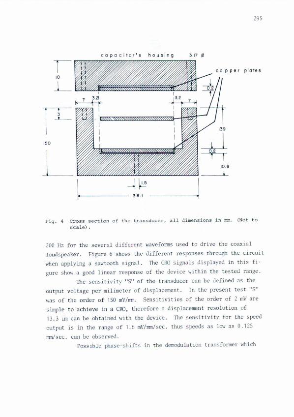
Figure 4 shows a sectional view of the capacitor. The mavable
part of the tr.:msducer eons ists of the capad tor' s in'Jer disc aod of a
brass shJft soldercd to this disco Special attention must be given to
achieve a propcr al ignment of the shJft and the hole through the exter-
nal capacitor's housing in arder to avoid contacto The dcsign of the
electronic circuits i5 conventiona1; however, since the three p1.:lte
transuucer posscscs a high impcdance, sorne noise and interference prob-
Iems ooy arisc in the circuit, cQTlsequently, a matching circuit rnust fa.!.
low the transducer's output. This is sho\o,TIin rig. S, togcther with the
demodulator and diffcrenti:lting circuits. 1'h(' frequency of the oscilla-
tor ShO.••.11 in Fig. S was of SO !'JIz in 3ccordance to the cri teria mentionctl
in the previolls section.
finally. it must he mcntioneu that the desirn of the transduc-
tion system has not been optimi:w; neverthcIcss, it provides a simple
\,'ay of testing the principIe of operation.
s. PERFORH\~CE
Tests ..•..ere pcrfonncd using frcqucncics in the rangc of 10 to
295
plotes
10.8
I
-1~38.1l.
13.
ca po citor's housing 3.17 ti
,l-~== _coppe,
J_~~~~ ~, --r.
150
Fig. 4 Cross section of the transducer, all dimensions in mm. (Not toscale) .
200 Hz far the several different wavefoms usro to drive the coaxialloudspeakcr. Figure Ó shows the different rcsI~nscs through the circuit...•hen applying a S3\oi,tooth signal. The eRO signals displayed in this fi-
gure 5hm.•' a gocxi linear response oí the devicc within the tested range.nlC sensitivity "$" of the transduccr can be defined as the
outrut voltage rer milimctcr oí displaccrncnt. In the present test "$"
was oí the arder oí ISOmV/rrrn. Sensitivitics oí the arder oí 2 m\' are
simple to achicve in a CRO, thcrefore a displaccn~nt rcsolution oí13.3 j..lJTI can be obtained with the device. The scn~itivity for ~he spcedoutrut is in thc range of 1.6 mV/rnmlscc.thus spccds as low as 0.125
rnmIscc. can be observcd.Possiblc phasc-shifts in the dcmodul:ltion transfonncr .•..hich

296
--.~.xr-------------- ------------,I I1 ~ ~I1 u • ~I1 a:: •.• I
: J ;11 I~I' ;11 " ~ I
a: ~II l' : 1I .t1 ; 1r--~-------------------~1 -- N I '" 11' 1
1I •.•..•••X U ~
I l' 11 11 I1 ~~ I
I 11 l' 11 I
I1 :' • 11-- _ _ _ _ I - - - - - --, ~ 1
I l. ; I1 I ~ ~ I1 - I ~ : II ~ I o ~ II~ I
o I 1
l. 1 11; 1 II ~ 1 II ~ 1 I1 I IL---- L ~ J
e[moo".~a 100 1I :::
Fig. 5 Circuit diagram of the transduction system.

297
It Va I I
r--~--~L-_~~ 1
O,I~V 01\::7- _ IL __ ~ ~ __ ~ __
V, I [f -- ~-¡---'\-t -,----..,.--j-r-
J I \1, \1 1°L_'JJ--- JL~[__v.
o
b
e
d
e
f
9
Fig. 6 Schematical representation oí typical waveforms, responses andlinearity in the experimental array. Representations nat toscale.a) Oscillator waveforms (50 KHz). b) Sawtooth signal applied toan audio amplifier used to drive the loudspeaker (10 - 200 Hz).el Loudspeaker driving signal (10 - 200 Hz). d) Transducer Qut-puto e) Detected output waveform (displacement). f) Differen-tiating circuit output (speed). g) X - yeRO display showingthe linearity of the experimental array. Signal el i5 appliedto the X-axis eRO deflection plates, while e) i5 applied to theX-axis eRO deflection plates. VNon linearity "L":: 100lóvl (max)/ (max). "L" less than 5\.

298
will contribute to a OC offset to the X(t) output were not detectcd.The transducer can be calibrated with the aió oí another speed
detection device. In the present case a l'lissel MVC.-1S0~6ssbauer veloelty calibratar based on laser interferometry was used for calibratingand chccking accurately the operation oí the transducer.
Finally. it must be mentioncd that the perfo~~nceof the COI1-
ventional systcm was a150 observed, resulting in a noticeable hirh noisclevel output due to the cornmon mode operation oí this conventional arrang~mento
6. CQ\ICLlliIONS
The device has shown good scnsitivity and a rcasonable linearbehaviour, it is inexpensive, simple ano cxtrerncly versatile. It offersthe additional advantage oí having 10w noisc characteristics when com-pared to the conventional system.
APPENDIX
List of parts of the circuit sholtonin Fig. 5.
Resistors
R¡ Carbon film 10 Kn 1/2 IV
R, 2.2 Kn
R, 3.9 Kn
R.. 33 Kn "Rs 560 Kn
Ro. Re 180 Kn
R7 " 150 ¡¡
R, 150 Kn
capaci tors
C.,C2 polyes ter 0.68"fC, l"fC, 0.47"fCs ceramic 7Z0pf

299
Integrated CircuitsI1 ~~rational Amplifier CA 3140 RCA1, ~rational Amplifier IJ.! 301 National
Transfonner
TRl Ferri te Core 1: 1 cr
DioJes
0,-0, Signal Diode lN914
The assistance oí the workshops oí Centro Nuclear de ~rxico isgratcfully acknOh'ledged. Patcnt is becn applied on this circuit arran~ment for the Instituto Nacional de Investigaciones Nucleares, ~~xico.
(Sepafin No. 188436).
REFERENCF.5
l. OeVoe, J.R .• "Radiochemical analysis: activation analysis instrumentation, radiation techniques. and radioisotope techniques". NBS-TN-276~National Bureau of Standars, Washington, D.C. (1966).
2. Fritz, R. and Sehulze, D., Instr. Methods, 62 (1968) 317.3. Flinn, P.A., Rev. SeL Instr., 34 (1963) 1422-6.4. Ellis, J.F. and Walstrom, P.L.,Rev. SeL Instrum., 49 (1978) 398-400.5. Greer, S.C., Moldover, M.R. and Hoeken, R., Rev. Sei-:-Instrum., 45
(1974) 1462-3.6. Kaplan. B.Z .• Mishal, R.• Fetman. A. and Gressel, C.• Rev. Se;. Instrum .•
49 (1978) 1583-8.7. Kaman Measur~ng Systems. "Electron;c Micrometer Systems", Kaman Seieo.
ces Corporation, Colorado Springs Co. (1966).8. Doeblin, E.O., Measurement Systems, MeGraw-Hill (1975) p. 253.9. Diefenderfer. A.J., Principles of electronic instrumentat;on, W.B.
Saunders Co. (1972) p. 88.