capacitors - vi engineeringviservices.com/files/2011cedcapacitors.pdf · capacitor ratings...
TRANSCRIPT
Capacitors
Dominik Pieniazek, P.E. – VI Engineering, LLCNicholas A. Losito Jr. – Castle Power Solutions, LLC

Outline
Day 1Day 1• Basic Power Calculations• Capacitor Fundamentals• Capacitor Ratings• Capacitor Application• Capacitor ProtectionpDay 2• Harmonics• Capacitor Bank Design Considerations• Capacitor Bank Design Considerations

Shunt Capacitors• Medium Voltage• Substation Applicationspp• Power Factor Correction

Basic Power Calculations

Basic Power Calculations
C Q tiCommon Questions:
What are VARs?Wh d b t VAR ?Why do we care about VARs?
Basic Power Calculations
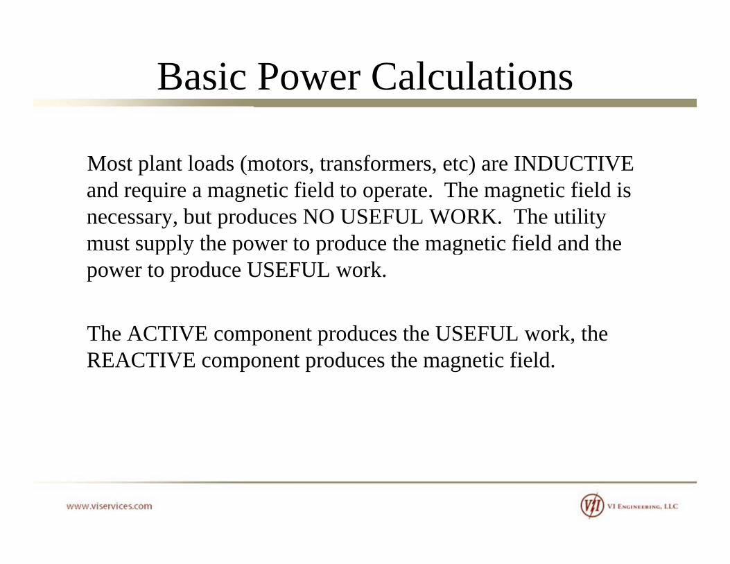
Most plant loads (motors, transformers, etc) are INDUCTIVE and require a magnetic field to operate. The magnetic field is necessary, but produces NO USEFUL WORK. The utility must supply the power to produce the magnetic field and themust supply the power to produce the magnetic field and the power to produce USEFUL work.
The ACTIVE component produces the USEFUL work, the REACTIVE component produces the magnetic field.

Basic Power Calculations
An analogy that
VAR
gymost can understand.
Mugi f i
VA
Capacity of equipment (i.e. xfmr, cable, swgr, etc)
Beer
W
eeStuff that you want
Foam (Head)St ff hi h tStuff which prevents you from maximizing the amount of beer that you get

Basic Power Calculations
f lV: Reference voltageIR: Resistive loadIL: Inductive loadI : Capacitive loadIC: Capacitive load
Basic Power Calculations
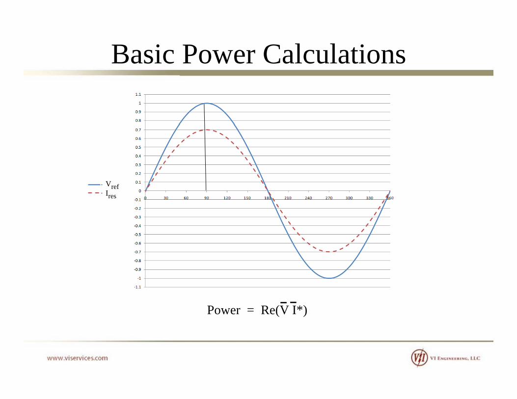
VrefIres
Power = Re(V I*)

Basic Power Calculations
VrefIlag
Note that due to phase shift (30 degrees) only 86.66% of current is applied to calculate work. Power = Re(V I*)

Basic Power Calculations
VrefIlead
Regardless whether leading or lagging, power calculation yields similar resultsPower = Re(V I*)
Basic Power Calculations
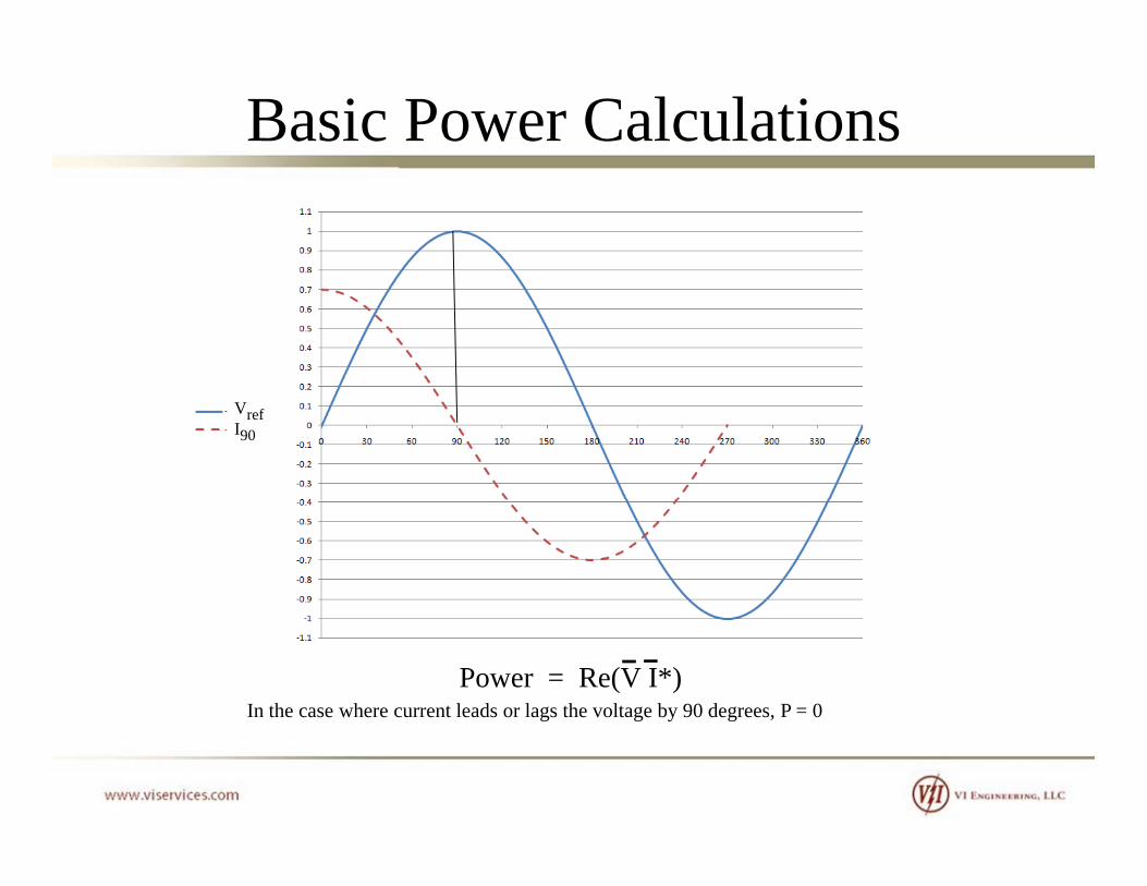
VrefI90
In the case where current leads or lags the voltage by 90 degrees, P = 0Power = Re(V I*)

Basic Power Calculations
Power Factor [ PF ] = Cos = P / S
S (kVA)
Q (kVAR)
P (W)Power Triangle
The relationship between S, P, and Q. This figure represents a lagging power factor. If Q is negative, leading power factor.
g

Basic Power Calculations
So how do we know if our current is lagging or leadingcurrent is lagging or leading the voltage, and what can we do to correct it?do to correct it?
Consider this exampleConsider this example,
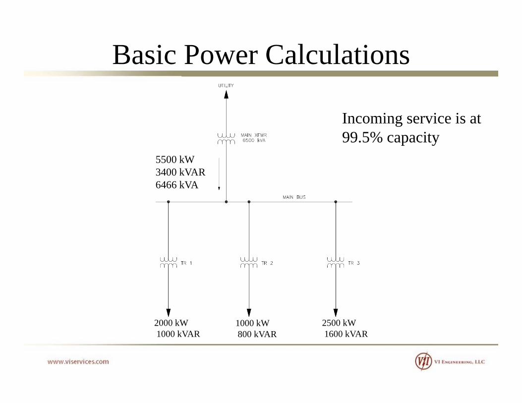
Basic Power Calculations
Incoming service is at
5500 kW3400 kVAR
g99.5% capacity
6466 kVA
2000 kW 1000 kW 2500 kW1000 kVAR 800 kVAR 1600 kVAR

Basic Power Calculations
Power Factor [ PF ] = Cos = P / S0.85 lag
S (kVA)
g
Q (kVAR)3400 kVAR
31.8 deg
P (W)Power Triangle
5500 kW g
Even though our facility require only 5500 kW to perform Real Work, our incoming service must be sized for 6466 kVA.

Basic Power CalculationsWe have a 6500 kVA mugthat is holding 5500 kWand 3400 kVAR.
VAR
VA
W
With the existing configurationthe facility cannot add any loadsy ywithout upgrading the incoming service.
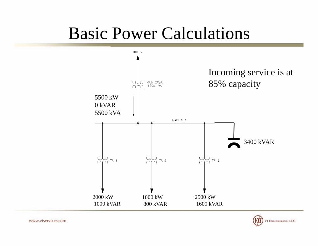
Basic Power Calculations
Incoming service is at
5500 kW0 kVAR
g85% capacity
5500 kVA
3400 kVAR
2000 kW 1000 kW 2500 kW1000 kVAR 800 kVAR 1600 kVAR
Basic Power Calculations
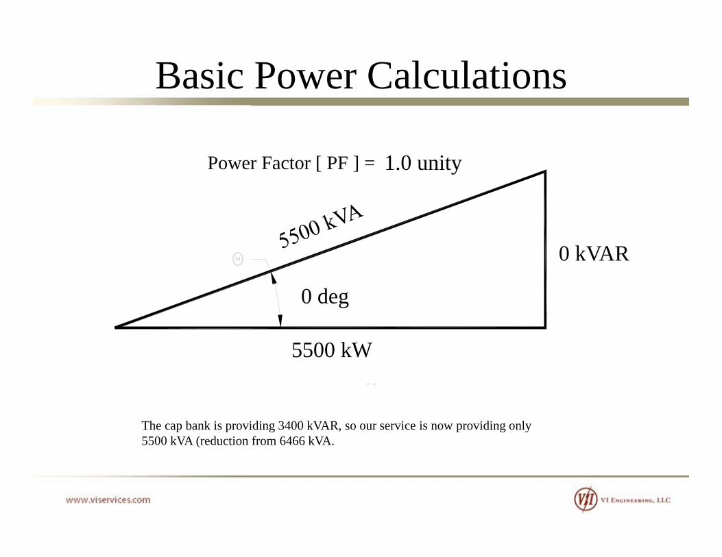
Power Factor [ PF ] = Cos = P / S1.0 unity
S (kVA)
y
Q (kVAR)0 kVAR
0 deg
P (W)Power Triangle
5500 kW g
The cap bank is providing 3400 kVAR, so our service is now providing only 5500 kVA (reduction from 6466 kVA.

Basic Power Calculations
1,500 kVA
COS [ ] = 0.67COS [ ] = 0.95
Q2 = Q1 + Qc Q1 = 1,118 kVAR
1 000 kW
1,053 kVA
Q2 = 330 kVAR 1,000 kWQ
Qc = 788 kVARRequired Apparent Power
Before and AfterAdding a Power Capacitor Bank
An example of how to calculate the size of a cap bank based on a target power factor

Basic Power Calculations
But wait, there’s more….

Basic Power Calculations
Odds are that the utility is
5500 kW3400 kVAR
ycharging you for penalties for a low power factor.
6466 kVA55006466
= 0.85
Typically, penalties are applied for power factor lessapplied for power factor less than 0.95%.
2000 kW 1000 kW 2500 kW1000 kVAR 800 kVAR 1600 kVAR

Basic Power Calculations
There are also voltage
5500 kW3400 kVAR
gconsiderations.
Assuming typical values:6466 kVA
Assuming typical values: Source impedance = 9% at 6500 kVAVolt Drop = 5.8%
The expected voltage drop atthe main bus will be close to6%!
2000 kW 1000 kW 2500 kW1000 kVAR 800 kVAR 1600 kVAR

Basic Power CalculationsCapacitor bank reduces the voltage drop at main bus
5500 kW0 kVAR
voltage drop at main busby 5%!
5500 kVA
Volt Drop = 1.0%
3400 kVAR
2000 kW 1000 kW 2500 kW1000 kVAR 800 kVAR 1600 kVAR

Basic Power CalculationsNote that the capacitor bank can also raise the bus voltage
5500 kW-1600 kVAR
gabove the nominal value.
5728 kVA
Volt Drop = -1.5%
5000 kVAR
2000 kW 1000 kW 2500 kW1000 kVAR 800 kVAR 1600 kVAR

Basic Power CalculationsThe voltage continues to riseif the capacitor bank remains
3000 kW-3200 kVAR
pconnected and the load is reduced.
4386 kVA
Volt Drop = -3.6%
5000 kVAR
Out of service
2000 kW 1000 kW 0 kW1000 kVAR 800 kVAR 0 kVAR

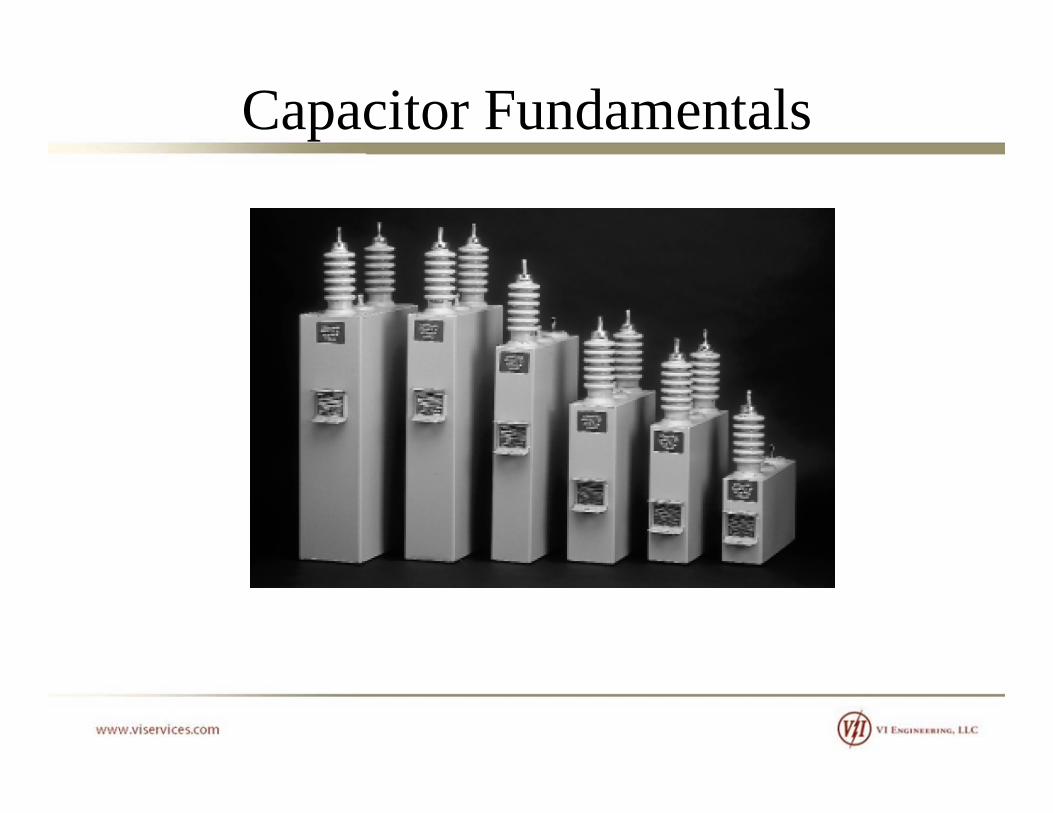
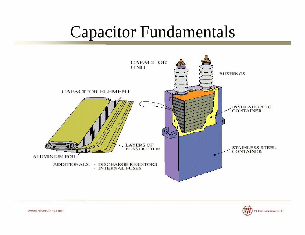
Capacitor Fundamentals

Capacitor Fundamentals
C = eo A / d for a parallel plate capacitor, where eo is the permittivity of the insulating material (dielectric) obetween plates.

Capacitor Fundamentals
We recall that we can add series capacitances to
1 / C = 1 / C1 + 1 / C2
We recall that we can add series capacitances to obtain an equivalent capacitance.
1 / Ceq 1 / C1 + 1 / C2
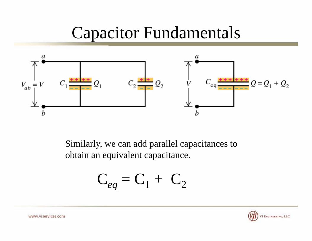
Capacitor Fundamentals
Similarly, we can add parallel capacitances to obtain an equivalent capacitance.
Ceq = C1 + C2

Capacitor Fundamentals…but we typically do not have much use for capacitance values. So we convert capacitance to impedance:So we convert capacitance to impedance:
fCCXC 2
11
fCCC 2

Capacitor Fundamentals
cjXRZ
cjXRZ
CXZ
VZ2
XVS
2
S CX

Capacitor Fundamentals
1000*][][2
kVVkVARS 000
][][
ZkVS
Example:Example:The capacitance of a capacitor is 6.22 F and the nameplate voltage is 8000 V. Calculate the power rating.
][7.426)1022.6)(60)(14.3(2
16 x
XC
][150000,17.426
)8( 2
kVARS
Capacitor Fundamentals

Capacitor Fundamentals

Capacitor Fundamentals

Capacitor Fundamentals
Capacitor Fundamentals

Capacitor FundamentalsNote that IEEE Std 18 requires the discharge
Discharge resistor
requires the discharge resistor to reduce the terminal voltage to 50 V in th ti f ifi dthe time frame as specified in the table below.

Capacitor Ratings

Capacitor Ratings
Medium voltage capacitors are available in many different stylesMedium-voltage capacitors are available in many different styles. The main points of differentiation are listed below:
• Voltage rating• kVAR rating• Single bushing or dual bushingg g g• Internally fused, externally fused, or fuseless

Capacitor Ratings
IEEE 81 defines the ratings for capacitorsIEEE 81 defines the ratings for capacitors
• Voltage, rms (terminal to terminal)• Terminal-to-case (or ground) insulation class• Reactive power• Number of phasesp• Frequency

Capacitor Ratings
IEEE 18 provides capacitor tolerancesIEEE 18 provides capacitor tolerances• The capacitance shall not vary more than -0% to +10% of
nominal value based on rated kVAR, voltage, and frequency measured at 25 deg C.
This means that a new 150 kVAR unit can range anywhere from g y150 kVAR to 165 kVAR.
Capacitor Ratings
IEEE 18 states the capacitor is intended to operate at or belowIEEE 18 states the capacitor is intended to operate at or below rated voltage. Capacitors shall be capable of continuous operation given that none of the following limitations are exceeded: • 110% of rated rms voltage (temporary overvoltage parameters
will be discussed later))• 120% of peak voltage, including harmonics but excluding
transients• 135% of nominal rms current based on rated kVAR and rated• 135% of nominal rms current based on rated kVAR and rated
voltage• 135% of rated kVAR

Capacitor Ratings
* Impulse tests shall be applied between terminals and case, with the terminals connected together. For capacitorshaving bushings with two different BIL ratings, this test shall be based on the bushing with the lowerBIL. The nameplate shall show both BIL ratings, e.g. 150/95 kV BIL.
** Not applicable to indoor ratings

Capacitor Application
Capacitor Application
Power factor correction capacitor banks are typically installed inPower factor correction capacitor banks are typically installed in the following ways :
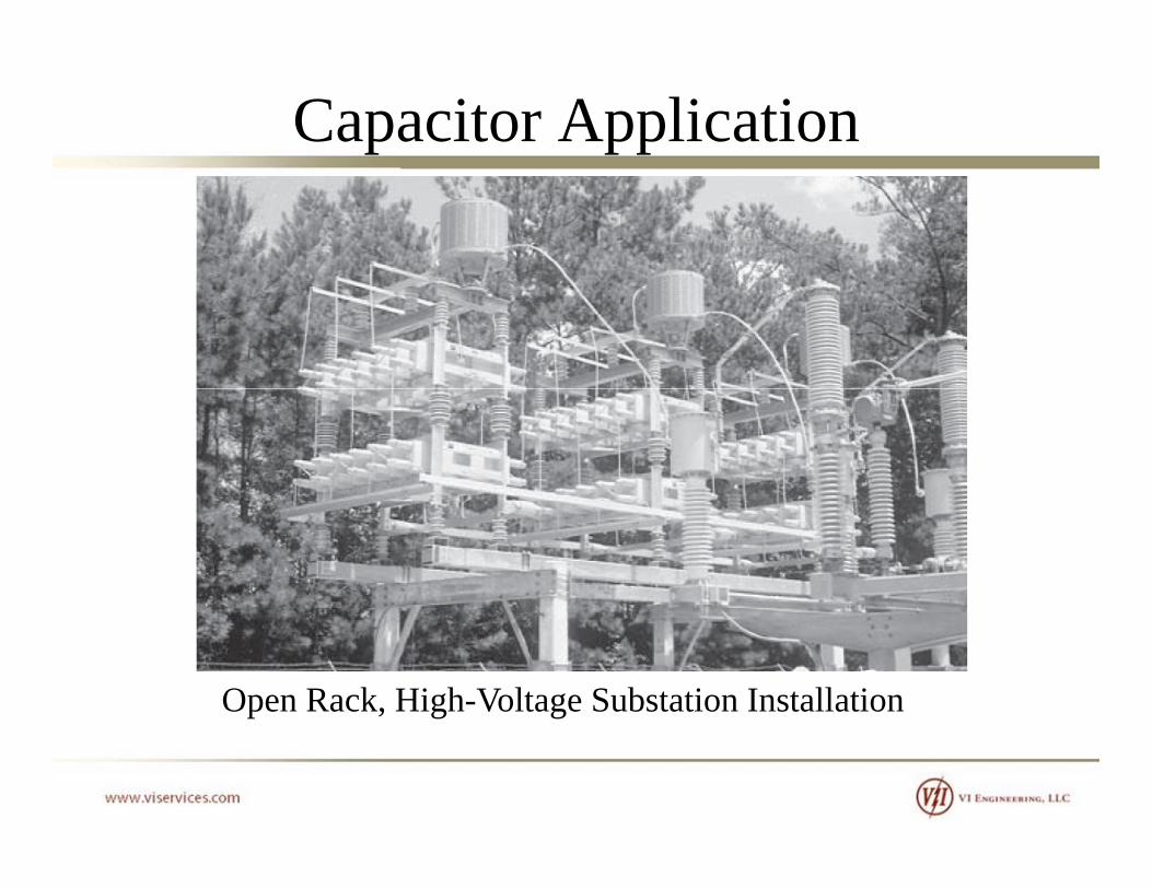
• Pole top• Metal-Enclosed / Pad-Mount• Open rackOpe ac• Terminal end at equipment

Capacitor Application
P l T I t ll tiPole Top Installation

Capacitor Application
Transient inrush reactors
P l T I t ll tiPole Top Installation

Capacitor Application
Pad Mounted InstallationPad-Mounted Installation

Capacitor Application
Metal-Enclosed Substation InstallationMetal Enclosed Substation Installation

Capacitor Application
Three-phase iron core harmonic filter reactor
Metal-Enclosed Substation Installation
harmonic filter reactor
Metal Enclosed Substation Installation

Capacitor Application
Open Rack, Medium-Voltage Substation Installation
Capacitor Application
Open Rack, High-Voltage Substation Installation

Capacitor Application
Installation in Equipment
Capacitor Application
Power factor correction capacitor banks can be configured in thePower factor correction capacitor banks can be configured in the following ways :
• Delta • Wye - Solidly Grounded• Wye - Ungroundedy g
A common misconception is that the capacitor bank should be connected Delta since it is being applied to a delta or highconnected Delta since it is being applied to a delta or high-impedance grounded system. This is NOT true.

Capacitor Application
The driving factor which determine the configuration for the given application is COST.
Voltage considerationsVoltage considerations
IEEE 1036 suggests that only banks rated 2400 V and below should be Delta connected This is mainly because standardshould be Delta connected. This is mainly because standard voltage ratings for wye connected banks may not be available.
Cost of phase-to-phase vs phase-to-neutral rated capacitors at higher voltages tends to point installations towards wye connected banks for larger bank installations.connected banks for larger bank installations.

Capacitor Application
DeltaLower voltages (<= 2400 V)• Standard capacitors are typically not available at 1380 V
Distribution systems (pole top)• Units are configured with a single series group of capacitors
with capacitors rated phase to phase Therefore unbalancewith capacitors rated phase-to-phase. Therefore, unbalance detection is not required.

Capacitor ApplicationWye – Solidly Grounded• Initial cost of the bank may be lower since the neutral does not
have to be insulated from groundhave to be insulated from ground.• Capacitor switch recovery voltages are reduced• High inrush currents may occur in the station ground system
Th d d id l i d f l• The grounded-wye arrangement provides a low-impedance fault path which may require revision to the existing system ground protection scheme. Typically not applied to ungrounded systems.p yp y pp g y
• When applied to resistance-grounded systems, difficulty in coordination between capacitor fuses and upstream ground protection relays (consider coordination of 40 A fuse with a 400 Aprotection relays (consider coordination of 40 A fuse with a 400 A grounded system).
• Typical for smaller installations (since auxiliary equipment is not i d)required)

Capacitor ApplicationThe most common capacitor bank configurations for larger substation applications are Wye-Ungrounded
Three of the most common unbalance protection schemes are shown. Discussion of the protection schemes will be presented later.
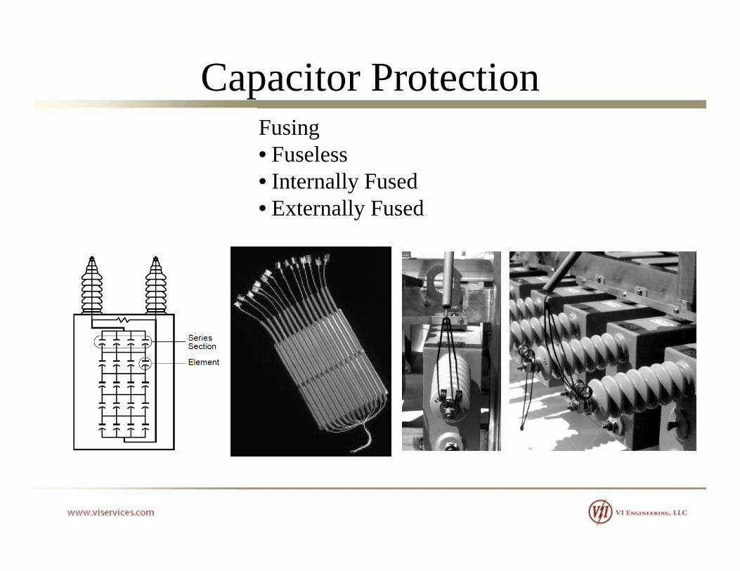
Capacitor ProtectionFusing• Fuseless
I t ll F d• Internally Fused• Externally Fused
Capacitor Protection
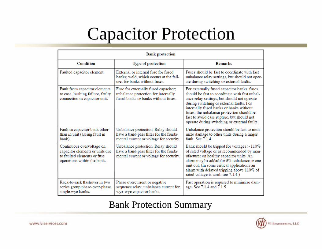
B k P t ti SBank Protection Summary

Capacitor Protection
Fuseless CapacitorsConstr cted of small capacitor elements hich are arranged inConstructed of small capacitor elements which are arranged in
series and parallel. The elements are constructed of aluminum foil with a dielectric of electrical grade polypropylene. This design provides a safe failure mode. In the event that the dielectric fails, the energy in the resulting small arc punctures many layers of the thin film and foil within the element. Themany layers of the thin film and foil within the element. The arc causes the film layer to receded allowing many layers of the aluminum foil electrodes to touch and weld together forming an electrically stable electrical joint This results in an entireelectrically stable electrical joint. This results in an entire series section being shorted.
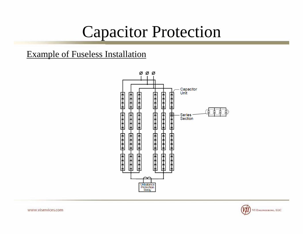
Capacitor ProtectionExample of Fuseless Installation
Capacitor Protection
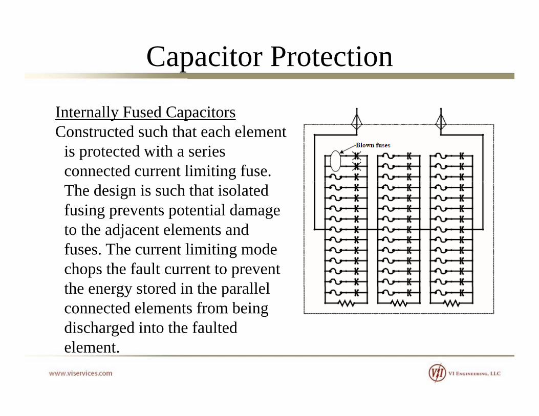
Internally Fused CapacitorsConstr cted s ch that each elementConstructed such that each element
is protected with a series connected current limiting fuse. The design is such that isolated fusing prevents potential damage to the adjacent elements andto the adjacent elements and fuses. The current limiting mode chops the fault current to prevent the energy stored in the parallelthe energy stored in the parallel connected elements from being discharged into the faulted element.
Capacitor Protection
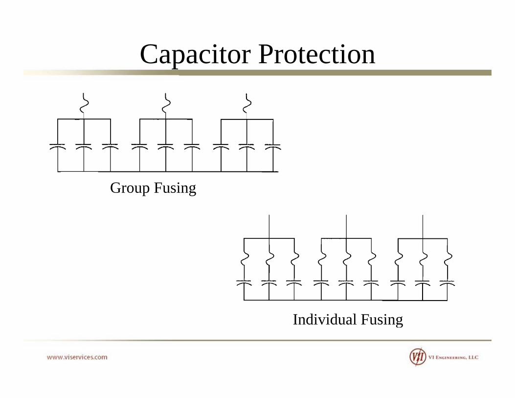
Group Fusing
Individual Fusingd v du us g

Capacitor ProtectionGroup Fusing– Considerations for Selecting Fuse(typical for distribution pole mounted racks) • Continuous Current• Continuous Current• Transient Current• Fault Current
k C C di i• Tank Rupture Curve Coordination• Voltage on Good Capacitors
Capacitor ProtectionContinuous Current• For wye-solidly grounded systems: Fuse > = 135% of rated
capacitor current (includes overvoltage, capacitor tolerances, and harmonics).
• For wye-ungrounded systems: Fuse > = 125% of rated y g ycapacitor current (includes overvoltage, capacitor tolerances, and harmonics).
Care should be taken when using NEMA Type T and K tin links which are rated 150%. In this case, the divide the fuse rating by 1.50.g y
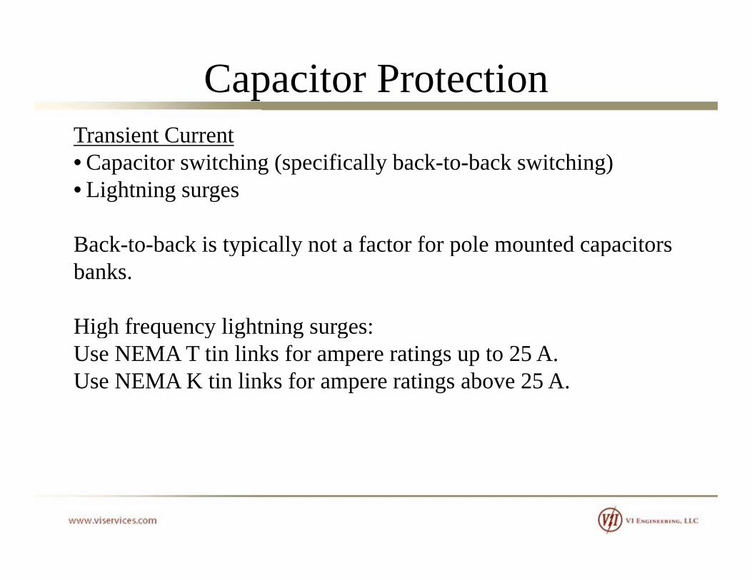
Capacitor ProtectionTransient Current• Capacitor switching (specifically back-to-back switching)• Lightning surges
Back-to-back is typically not a factor for pole mounted capacitors yp y p pbanks.
High frequency lightning surges:High frequency lightning surges:Use NEMA T tin links for ampere ratings up to 25 A.Use NEMA K tin links for ampere ratings above 25 A.

Capacitor ProtectionFault CurrentEnsure that the fuse can interrupt the available fault current
Tank Rupture CoordinationEnsure that the fuse maximum clearing TCC curve for the fuse glink is plotted below the capacitor tank rupture curve. In cases of high fault currents, the tank rupture curve should be compensated for asymmetryfor asymmetry.
Voltage on Good Capacitorsd d f l h l iFor an ungrounded system, a fault on one phase results in a 1.73
times overvoltage on the un-faulted phases. Ensure that the fault is cleared before the second capacitor failure.p
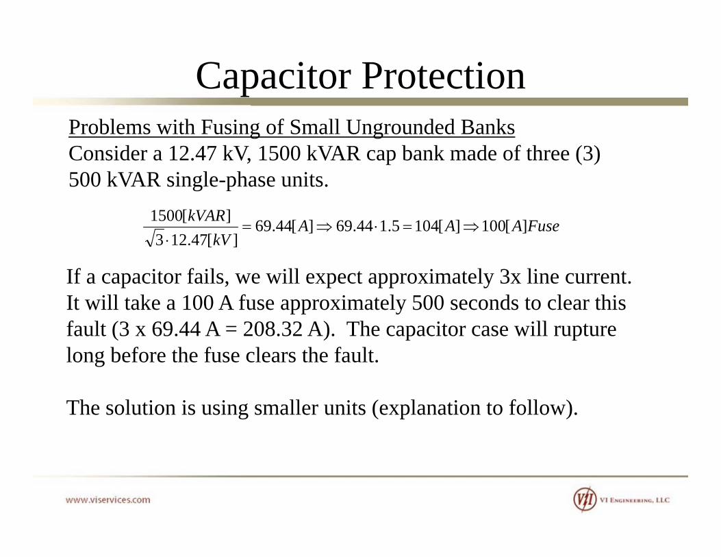
Capacitor ProtectionProblems with Fusing of Small Ungrounded BanksConsider a 12.47 kV, 1500 kVAR cap bank made of three (3) 500 kVAR i l h i500 kVAR single-phase units.
FuseAAAkV
kVAR ][100][1045.144.69][44.69][47.123
][1500
kV ][47.123
If a capacitor fails, we will expect approximately 3x line current.It will take a 100 A fuse approximately 500 seconds to clear this pp yfault (3 x 69.44 A = 208.32 A). The capacitor case will rupture long before the fuse clears the fault.
The solution is using smaller units (explanation to follow).
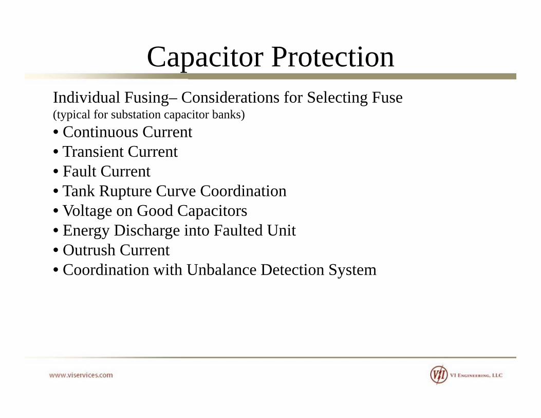
Capacitor ProtectionIndividual Fusing– Considerations for Selecting Fuse(typical for substation capacitor banks) • Continuous Current• Continuous Current• Transient Current• Fault Current• Tank Rupture Curve Coordination• Voltage on Good Capacitors• Energy Discharge into Faulted UnitEnergy Discharge into Faulted Unit• Outrush Current• Coordination with Unbalance Detection System
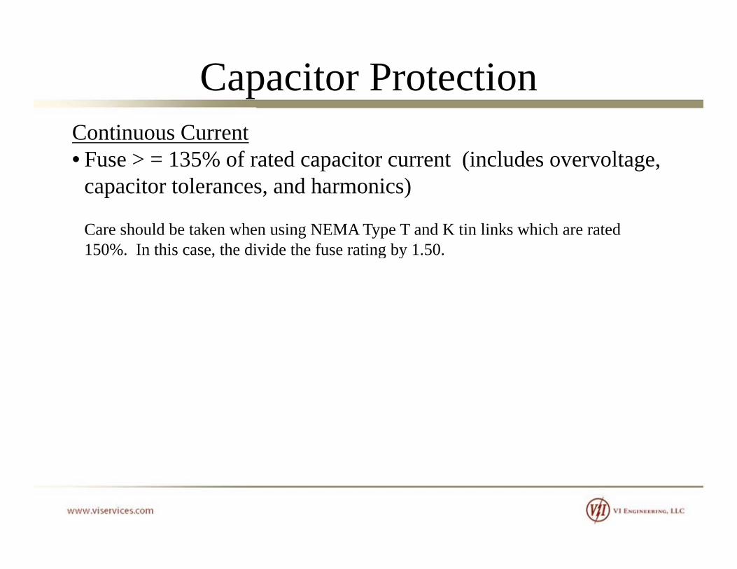
Capacitor ProtectionContinuous Current• Fuse > = 135% of rated capacitor current (includes overvoltage,
capacitor tolerances, and harmonics)
Care should be taken when using NEMA Type T and K tin links which are rated 150% In this case the divide the fuse rating by 1 50150%. In this case, the divide the fuse rating by 1.50.

Capacitor ProtectionTransient Current• Lightning surges• Capacitor switching (specifically back-to-back switching)
High magnitude, high frequency lightning surges are typically not g g , g q y g g g yp ya concern for substation installations.
Back to back switching is typically controlled with pre insertionBack-to-back switching is typically controlled with pre-insertion closing resistors or current limiting reactors.
h f i ll i h ll l f ill h hBy the nature of installation, the parallel fuses will share the transient current and will not be a factor.

Capacitor ProtectionFault CurrentEnsure that the fuse can interrupt the available fault current.
In substation banks with multiple series groups, fault current will not flow through a failed capacitor unit unless other units g pexperience a simultaneous failure. For this reason expulsion fuses are commonly used rather than current limiting fuses
Tank Rupture CoordinationEnsure that the fuse maximum clearing TCC curve for the fuse li k i l d b l h i k flink is plotted below the capacitor tank rupture curve. In cases of high fault currents, the tank rupture curve should be compensated for asymmetry.y y

Capacitor Protection
Example of a DefiniteExample of a Definite Tank Rupture Curve.
Th i b hThe time between the rupture curve and the fuse maximum clear curve is the coordination margin.

Capacitor Protection
Example of a 10% and 50% Rupture Curve for a 100 kVARRupture Curve for a 100 kVAR Capacitor.
Probability based tank rupture y pcurves are developed when there is too much variance in rupture test data.
Based on the 10% and 50% curves, one can extrapolate the
f b bilicurves for any probability.

Capacitor ProtectionVoltage on Good CapacitorsWhen a short-circuit on one unit occurs, an overvoltage results on the un-faulted phases. Ensure that the fault is cleared before the second capacitor failure. A table summarizes this voltage rise on the un-faulted units
Per Unit Voltage on Un-failed Capacitors

Capacitor ProtectionEnergy Discharge Into a Failed UnitWhen a capacitor failure occurs, the stored energy in the parallel connected capacitors can discharge thro gh the failed capacitorconnected capacitors can discharge through the failed capacitor and its fuse. The total calculated parallel stored energy should not exceed the energy capability (Joule rating) of the capacitor and fuse. If the energy capabilities are exceeded, a failure of the fuse and/or rupture of the capacitor tank can result.
Typical rating of film capacitors is 15,000 Joules (4650 kVAR in parallel) and 10,000 Joules (3100 kVAR in parallel) for paper-film capacitors Expulsion fuses are typically rated 30 000film capacitors. Expulsion fuses are typically rated 30,000 Joules. Current limiting fuses are required if ratings are exceeded.
(1 Joule = 1 W x sec use 0 2 cycle clearing time for calculation)(1 Joule = 1 W x sec, use 0.2 cycle clearing time for calculation)

Capacitor ProtectionOutrush CurrentWhen a capacitor failure occurs, the parallel connected capacitors can discharge high frequency current into the failed capacitor. The fuses of the un-failed capacitors should be able to withstand the high frequency discharge currents. These calculations and g q y gmeasurements are complex and are determined by the manufacturer.
Coordination with Unbalance Detection SchemeThe individual fuse must clear the fault before the unbalance
i h i h i i b kprotection scheme trips the entire capacitor bank.

Capacitor ProtectionFusing Recommendations by McGraw Edison

Capacitor ProtectionRecall Problem with Fusing of Small Ungrounded Banks12.47 kV, 1500 kVAR cap bank made of three (3) 500 kVAR units
FuseAAAkV
kVAR ][100][1045.144.69][44.69][47.123
][1500
It will take a 100 A fuse approximately 500 seconds to clear thisIt will take a 100 A fuse approximately 500 seconds to clear this fault (3 x 69.44 A = 208.32 A). The capacitor case will rupture long before the fuse clears the fault.
The solution is using smaller units with individual fusing.Consider five (5) 100 kVAR capacitors per phase, each with a ( ) p p p ,25 A fuse. The clear time for a 25 A fuse @ 208.32 A is below the published capacitor rupture curve.

Capacitor ProtectionWhy is the Current 3 x Nominal Line Current for a Phase-to-Neutral Fault on a Wye-Ungrounded Capacitor Bank?
A
B
A
B
V
A
C
NAN
VNG C C
I 3 0Since V = I*Z, where Z is
t t ( i f 60 h ) IA = 3.0 p.u.constant (assuming f = 60 hz)If voltage across capacitor is increased by 1.732, the current also increases by factor of 1.732y

Capacitor Protection
Minimum Conductor SizeIt was noted that capacitors are rated 135% of rating. This requires the conductor to be sized 135% of the nominal capacitor ratingrating.
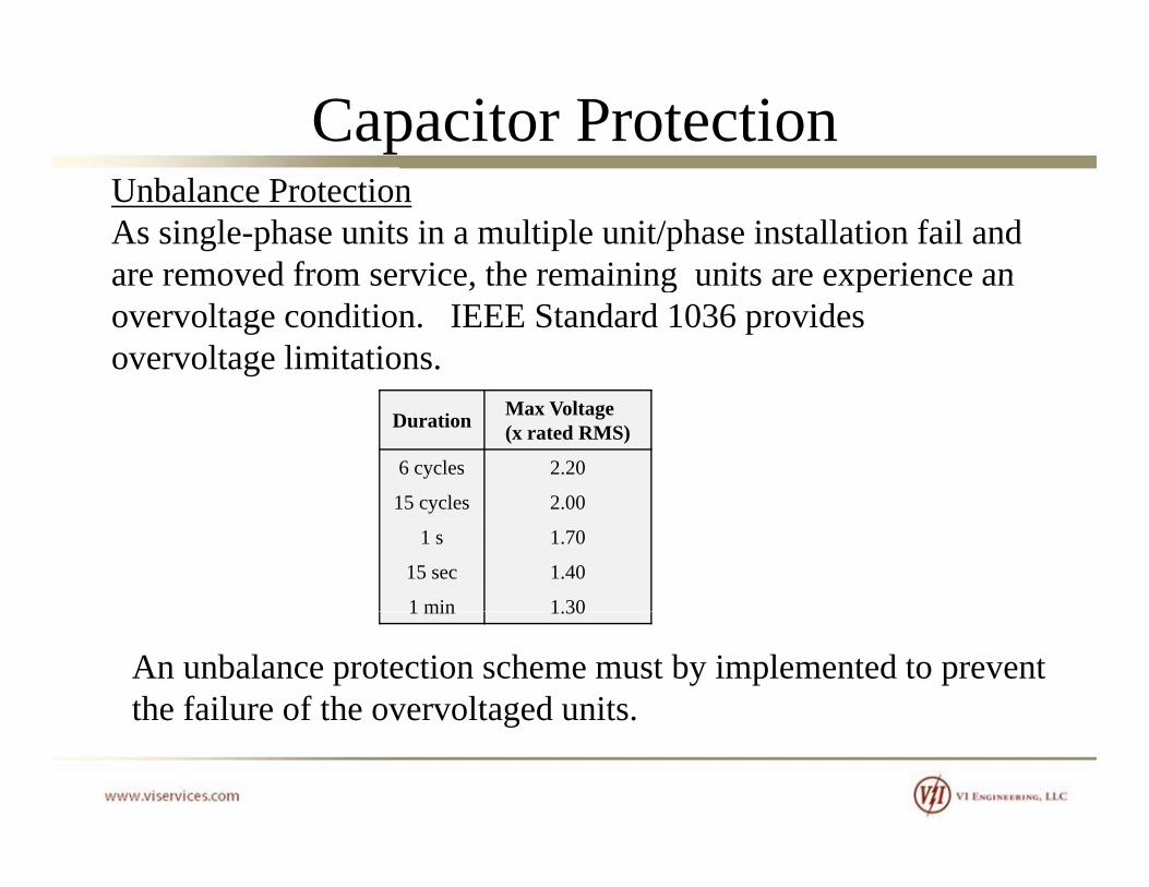
Capacitor ProtectionUnbalance ProtectionAs single-phase units in a multiple unit/phase installation fail and are removed from service the remaining units are experience anare removed from service, the remaining units are experience an overvoltage condition. IEEE Standard 1036 provides overvoltage limitations.
Duration Max Voltage (x rated RMS)
6 cycles 2.20
15 c cles 2 0015 cycles 2.00
1 s 1.70
15 sec 1.40
1 min 1.301 min 1.30
An unbalance protection scheme must by implemented to prevent the failure of the overvoltaged units. g

Capacitor Protection
Capacitor Protection
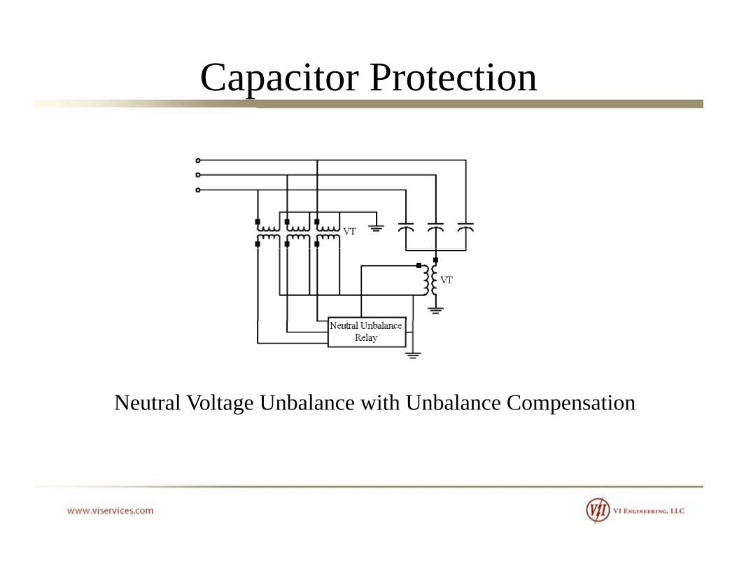
Neutral Voltage Unbalance with Unbalance Compensation

Capacitor Protection
VA
V
V
VNVGVNG
Normal ConditionsVN = VGVAN = VBN = VCN
VC VB
VAN VBN VCN
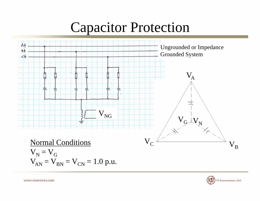
Capacitor ProtectionUngrounded or Impedance Grounded System
VA
V
V
VNVGVNG
Normal ConditionsVN = VGVAN = VBN = VCN = 1.0 p.u.
VC VB
VAN VBN VCN .0 p.u.
Capacitor Protection
VVNG
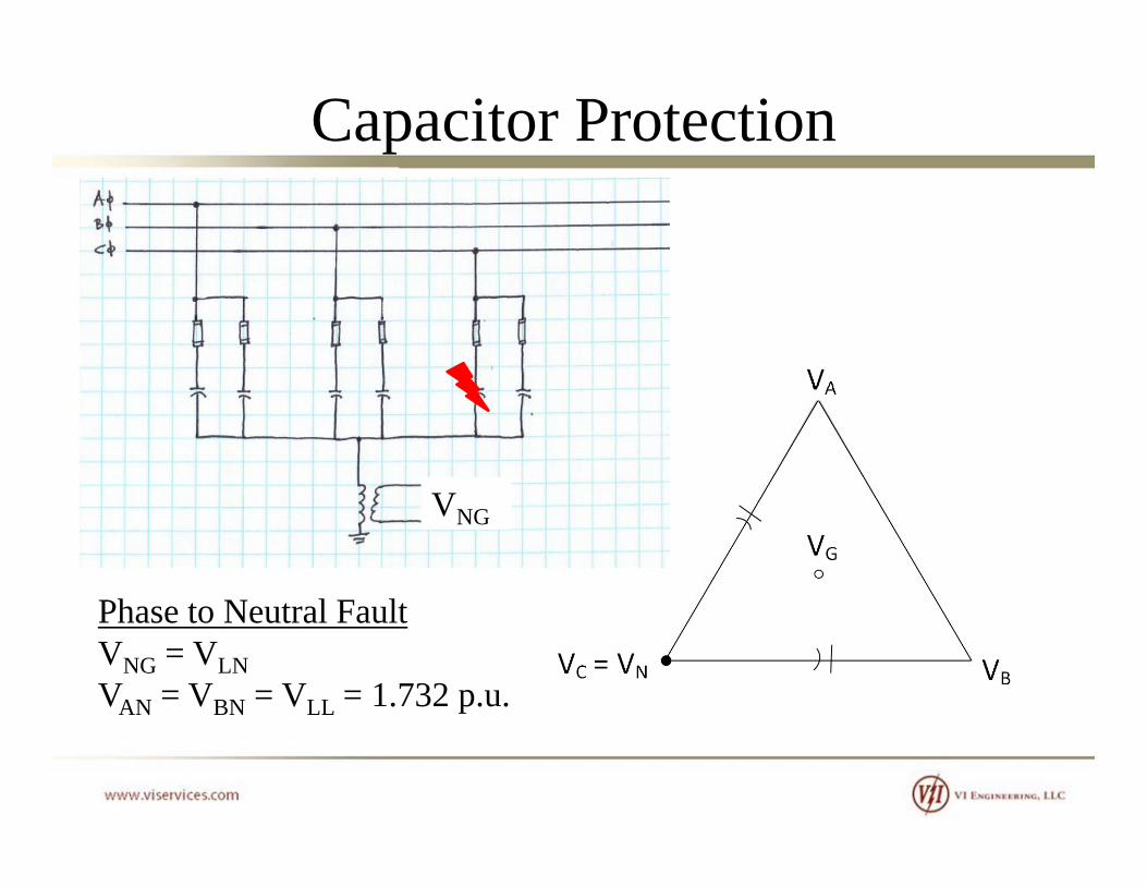
Phase to Neutral FaultPhase to Neutral FaultVNG = VLNVAN = VBN = VLL = 1.732 p.u.
Capacitor Protection
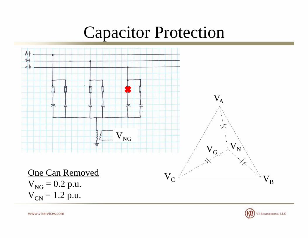
VA
VVNVG
VNG
One Can RemovedVNG = 0.2 p.u.V = 1 2 p u
VC VB
VCN = 1.2 p.u.

Capacitor ProtectionUngrounded or Impedance Grounded System
VA
V
V
VNVGVNG
Normal ConditionsVN = VGVAN = VBN = VCN = 1.0 p.u.
VC VB
VAN VBN VCN .0 p.u.
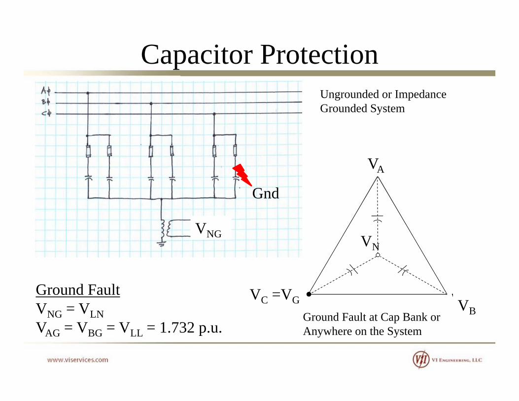
Capacitor ProtectionUngrounded or Impedance Grounded System
VA
V
Gnd
VNVNG
VC VB
Ground FaultVNG = VLNV = V = V = 1 732 p u
VC =VG
Ground Fault at Cap Bank or A h h SVAG = VBG = VLL = 1.732 p.u. Anywhere on the System

Capacitor Protection
Wye-Ungrounded: Voltage Between Capacitor Bank Neutral and Ground vs. Percentage of Capacitor Units Removed from Series Group

Capacitor Protection
Wye-Ungrounded: Voltage on Remaining Capacitor Units in Series Group vs. Percentage of Capacitor Units Removed from Series Group

Capacitor Protection
Wye-Grounded: Neutral Current vs Percentage of Capacitor Units Removed from Series Group
Capacitor Protection
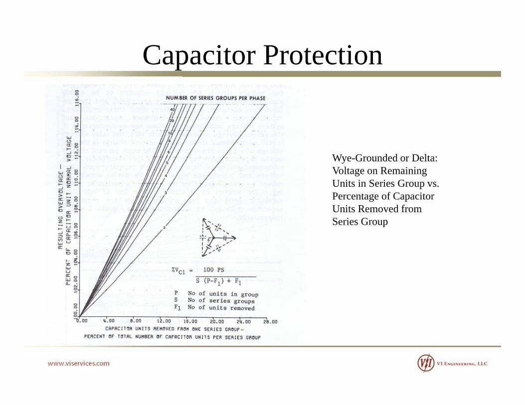
Wye-Grounded or Delta: Voltage on Remaining Units in Series Group vs. Percentage of Capacitor Units Removed from Series Group

Capacitor Protection
Double Wye-Ungrounded, Neutrals Tied Together: Neutral Current vs. Percentage of Capacitor Units Removed from Series Group

Capacitor Protection
Double Wye-Ungrounded, Neutrals Tied Together: Voltage on Remaining Capacitor Units in Series vs. Percentage of Capacitor Units Removed from Series Group
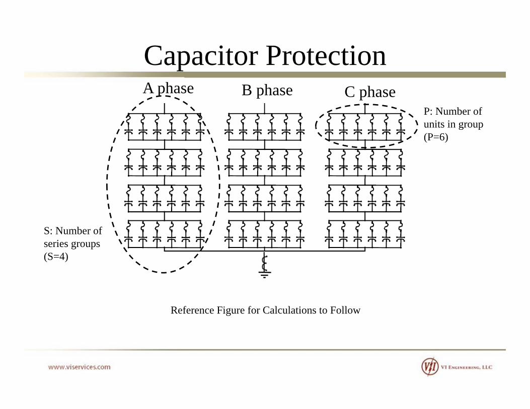
Capacitor ProtectionA phase B phase C phase
P: Number of units in groupunits in group(P=6)
S: Number ofS: Number of series groups(S=4)
Reference Figure for Calculations to Follow
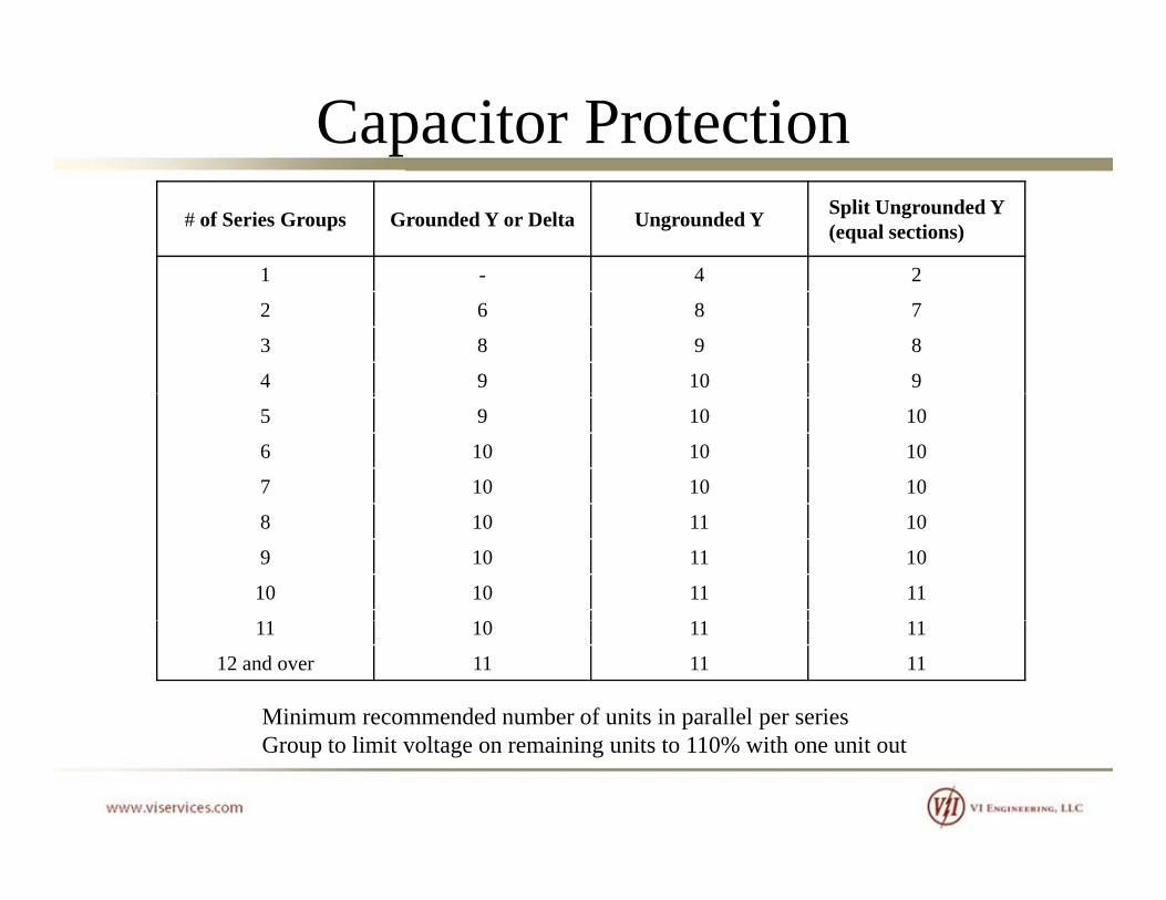
Capacitor Protection# of Series Groups Grounded Y or Delta Ungrounded Y Split Ungrounded Y
(equal sections)
1 - 4 21 4 2
2 6 8 7
3 8 9 8
4 9 10 9
5 9 10 10
6 10 10 10
7 10 10 10
8 10 11 10
9 10 11 10
10 10 11 11
11 10 11 11
12 and over 11 11 11
Minimum recommended number of units in parallel per seriesGroup to limit voltage on remaining units to 110% with one unit out

Capacitor Protection
Many more configurations and calculations shown in IEEE C37.99

Day 2Day 2

Capacitor FundamentalsFurther discussion on capacitor voltage ratings:
On a ungrounded or impedance grounded system, a ground fault on one phase will cause the other two phases will be elevated by 1 7321.732.
Does this mean that capacitors must be rated phase-to-phase?
Certainly nothing wrong with this, but cost will be significantly higher.g

Capacitor FundamentalsRecall:
XVS
2
CX
This means that a 150 kVAR 12470 V unit applied at 7200 VThis means that a 150 kVAR, 12470 V unit applied at 7200 V will provide only 50 kVAR.
][50
][150][12470][7200
2
2
kVARS
kVARVVSNEW
][50 kVARSNEW
Capacitor FundamentalsUsing 12470 V capacitors on a 12470 V Ungrounded or Resistance-Grounded System will require 3x more cans. y q
It should be noted that the 12470 V cans will also be larger than the 7200 V cansthe 7200 V cans.
Results in a much larger and more costly installation.
This solution would be required if a ground fault could be maintained for extended periods of time. p
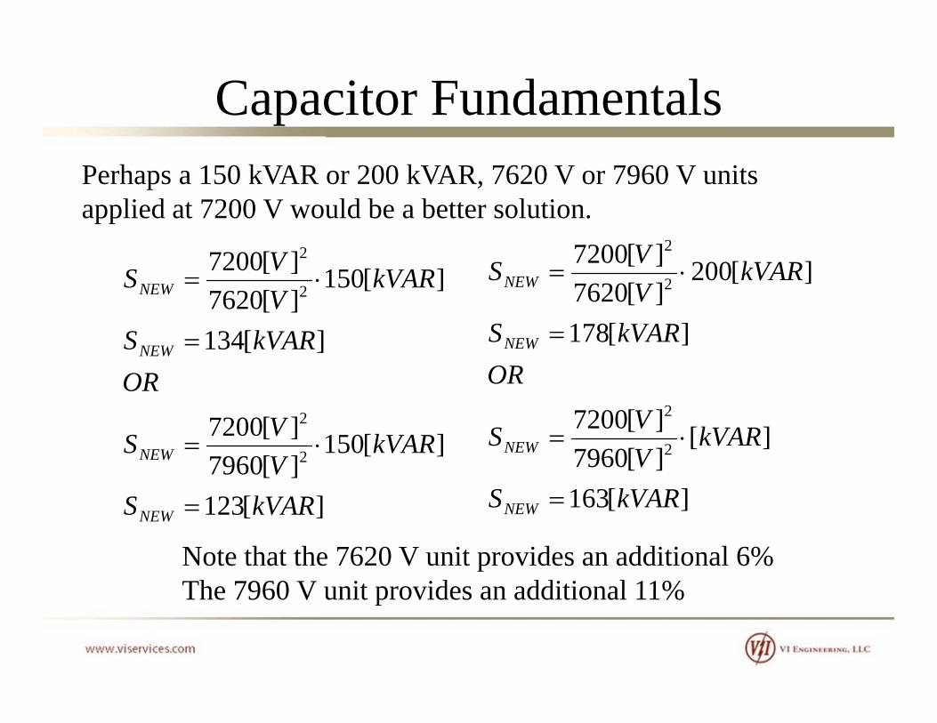
Capacitor FundamentalsPerhaps a 150 kVAR or 200 kVAR, 7620 V or 7960 V units applied at 7200 V would be a better solution.
][150][7620][7200
2
2
kVARVVSNEW ][200
][7620][7200
2
2
kVARVVSNEW
][134OR
kVARSNEW ][178
2
ORkVARSNEW
][123
][150][7960][7200
2
2
kVARS
kVARVVSNEW
][163
][][7960][7200
2
2
kVARS
kVARVVSNEW
][123 kVARSNEW
Note that the 7620 V unit provides an additional 6% The 7960 V unit provides an additional 11%
][163 kVARSNEW
The 7960 V unit provides an additional 11%

Capacitor FundamentalsExplusion Fuses:
Provides a means of disconnecting a failed capacitor from the circuit by melting a tin-lead low current link. The shorted capacitor unit causes a large increase in the current through the fuse. The current is limited only by the power system reactance and the other capacitor units in series with the failed capacitor unit. Thereactance and the other capacitor units in series with the failed capacitor unit. The pressure is generated by the hot arc making contact with the fiber lining of the fuse tube. The link is cooled and stretched as it is forced out the tube. The fuse continues to conduct until a natural current zero occurs. The current zero is
d b th t f lt t i If th itcaused by the power system fault current crossing zero. If other capacitors are connected in parallel with the failed unit, all the stored energy in these capacitors will be absorbed in either the fuse operation or the failed capacitor unit. Most of the energy is absorbed in the failed capacitor.gy p
Capacitor FundamentalsCurrent Limiting Fuses:
Uses a long uniform cross section element. This configuration makes the fuse a current chopping fuse. The fuse develops a back voltage per inch of element across the entire length of the element. When this voltage exceeds the available voltage across the fuse, the fuse forces the arc to extinguish. The result is that avoltage across the fuse, the fuse forces the arc to extinguish. The result is that a trapped voltage may and probably will remain on the other capacitors in the series group. The fuse by its design avoids absorbing all of the available energy on the series group. This fuse is used for capacitor banks with a large number of
ll l it It b d li ti ith ti ll i fi it ll lparallel capacitors. It can be used on applications with essentially infinite parallel stored energy, as long as sufficient back voltage can be developed to force the current to extinguish. This is the fuse we apply to series, large shunt, and DC banks.
Because of the high back voltage that is developed, this fuse must be used with several capacitors in parallel to limit the voltage build up or a flashover may occur elsewhere in the capacitor rackoccur elsewhere in the capacitor rack.
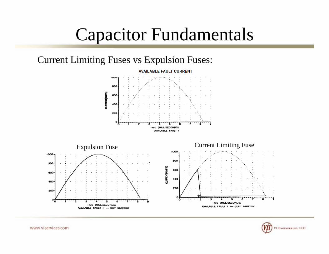
Capacitor FundamentalsCurrent Limiting Fuses vs Expulsion Fuses:
C Li i i FExpulsion Fuse Current Limiting Fuse

Capacitor FundamentalsCurrent Limiting Fuses vs Expulsion Fuses:
Expulsion FusesOperate mechanically and provide a visual indication
Require additional space for operationRequire additional space for operation
Typically applied for outdoor application due to ionized gas release.
C bi ti l i ith t li iti h t i ti f b d iCombination expulsion with current limiting characteristic fuses can be used in indoor metal-enclosed equipment.
Less expensivep

Capacitor Fundamentals

Capacitor FundamentalsCurrent Limiting Fuses
Do not emit ionized gases during operation Ionized gases are undesirableDo not emit ionized gases during operation. Ionized gases are undesirable because they can cause bushing and insulator flashovers that result in additional damage. Do not require ventilation.
Fast current-limiting operation
High interrupting capacity, noiseless operation
Can be specified for indoor and outdoor applications .
No pressure build-up, therefore, no vents or special reinforced compartments are i drequired.
More expensive

Capacitor FundamentalsNote no pigtail and blown fuse indication

Capacitor FundamentalsCurrent Limiting with Expulsion
Capacitor FundamentalsWhat about arresters? How and where should they be applied?applied?
Depending on application, environment, exposure to switching etc arresters may be necessaryswitching, etc, arresters may be necessary.
We recall that when a travelling wave meets a high impedance, the wave can double in size. For this reason, arresters (if used) should be installed as close to the capacitor bank as possible. Installation of arresters at the breaker pfeeding the capacitor bank will not do much for protection of the capacitor bank.

Capacitor ProtectionA basic three (3) arrester method is shown below. This is typical for solidly grounded systems and wye-groundedtypical for solidly grounded systems and wye grounded capacitor banks.
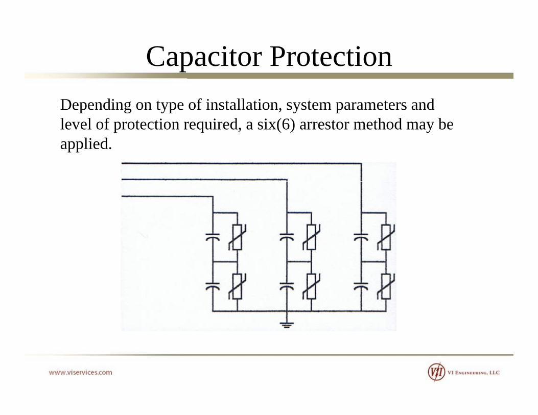
Capacitor ProtectionDepending on type of installation, system parameters and level of protection required, a six(6) arrestor method may belevel of protection required, a six(6) arrestor method may be applied.

Capacitor ProtectionFor an ungrounded system or a high-impedance grounded system, a four (4) arrestor grounding method might besystem, a four (4) arrestor grounding method might be considered an wye ungrounded bank.
Phase to Neutral FaultVNG = VLNNG LNVAN = VBN = VLL = 1.732 p.u.
Ground FaultVNG = VLN
VLL
VLL
ArrNG LNVAG = VBG = VLL = 1.732 p.u.
If faults can be maintained,ArrN
V ArrPH
ArrPH must be rated VLLArrN must be rated VLN
The effective arrester MCOV
N
is VLL + VLN

Capacitor ProtectionNote that if a basic three (3) arrester method is applied to an ungrounded bank, the arresters must be rated high enough to sustain a temporary overvoltage condition during a phase-to-ground fault on the system. This may not provide an adequate level of protection for the capacitors.
Phase to Neutral FaultVNG = VLNV V V 1 732VAN = VBN = VLL = 1.732 p.u.
Ground FaultVNG = VLNV V V 1 732
VLL
VLL
VAG = VBG = VLL = 1.732 p.u.
If faults can be maintained, Arresters must be rated VLL
V
Arresters do not provide protection across the capacitor bushings. Note that the BIL applies to bushing-to-
i l ticase insulation.

Capacitor ProtectionGood Presentations on Capacitor – Arrester Applications
“G id li f S l ti f S A t f Sh t“Guidelines for Selection of Surge Arresters for Shunt Capacitor Banks” – ABB Technical Information
“Surge Arrester Application of MV-Capacitor Banks to Mitigate Problems of Switching Restrike” – CIRED 19th
International Conference on Electricity Distribution ViennaInternational Conference on Electricity Distribution, Vienna, 21-24 May 2007.
B th f th l dd h t h tBoth of these papers also address phase-to-phase arrester connections.

Harmonics

HarmonicsRecall that the impedance of a capacitor is inversely proportional to the system frequencyproportional to the system frequency.
fCCXC 2
11
fCC 2
Harmonics flow to the point of lowest impedance. The higher the harmonic the lower the impedance of the capacitorthe harmonic, the lower the impedance of the capacitor.
As capacitors absorb harmonics, the capacitor heats up and th lif t i d d Th lt h i tthe life expectancy is reduced. The voltage harmonics stress the capacitor dielectric and reduce the life expectancy of the capacitor.

Harmonics

Harmonics
Where do harmonics come from?• Power Electronics (drives, rectifiers, computer power
supplies, etc)• Arcing Devices (welders, arc furnaces, florescent lights, etc)g ( , , g , )• Iron Saturating Devices (transformers)• Rotating Machines (Generators)• Parallel Resonance (between cap bank and power• Parallel Resonance (between cap bank and power
equipment)
IEEE Std 519 provides recommended limits of harmonic distortion at the point-of-common-coupling (PCC) with the utility.y

Harmonics

Harmonics
Harmonics
ResonanceWhen a number of harmonic current sources are injecting currents into the supply and the frequency of one of the harmonics coincides with the resonant frequency of the supply transformer andwith the resonant frequency of the supply transformer and Power Factor Correction capacitor combination, the system resonates and a large circulating harmonic current is excited between these components The result of this is that a largebetween these components. The result of this is that a large current at this harmonic flows in the supply transformer, this resulting in a large harmonic voltage distortion being imposed upon the load voltage.

Harmonics
A study should be performed to determine levels of harmonics on a y psystem to determine if any filters are necessary when installing a capacitor bank.
Care should be taken to determine if the filtered capacitor bank will introduce any resonance problems. If resonance problems exist, the fil d i b dj dfilter design must be adjusted.

Harmonics
An example of a 13 8 kV harmonic filterAn example of a 13.8 kV harmonic filter

Capacitor Bank Design Considerations
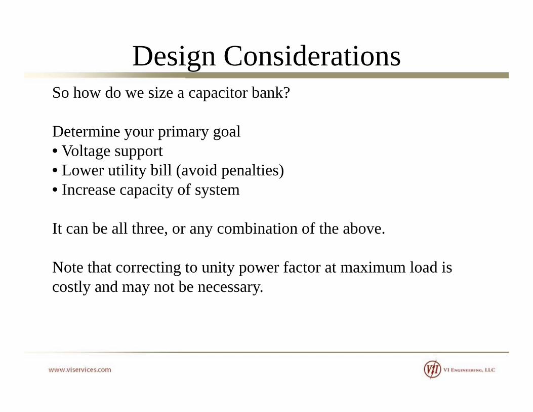
Design ConsiderationsSo how do we size a capacitor bank?
D t i i lDetermine your primary goal• Voltage support• Lower utility bill (avoid penalties)• Increase capacity of system
It can be all three, or any combination of the above.It can be all three, or any combination of the above.
Note that correcting to unity power factor at maximum load is tl d t bcostly and may not be necessary.
Design Considerations
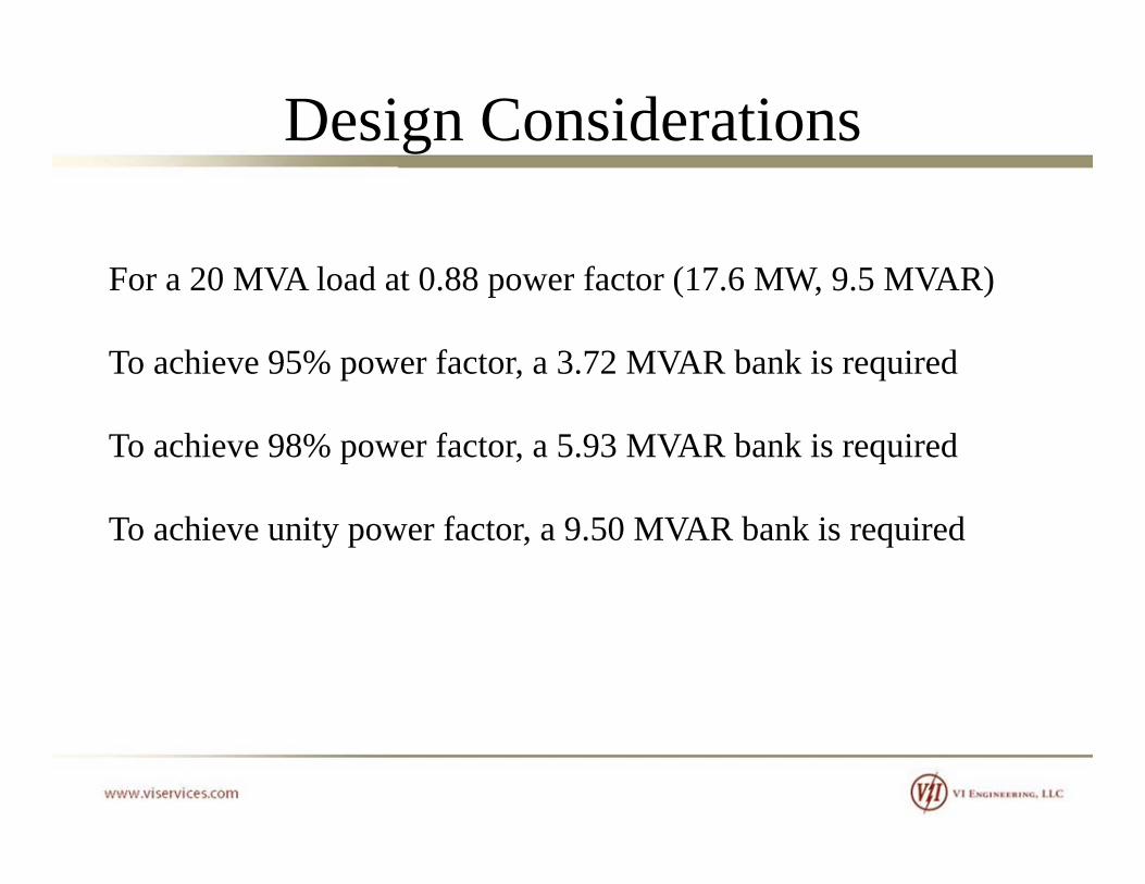
For a 20 MVA load at 0 88 power factor (17 6 MW 9 5 MVAR)For a 20 MVA load at 0.88 power factor (17.6 MW, 9.5 MVAR)
To achieve 95% power factor, a 3.72 MVAR bank is required
To achieve 98% power factor, a 5.93 MVAR bank is required
To achieve unity power factor, a 9.50 MVAR bank is required

Design Considerations
Determine if current limiting reactors or tuning reactors areDetermine if current limiting reactors or tuning reactors are required.
Harmonics and resonance may dictate tuning reactors
Back-to-back switching may require current limiting reactorsBack to back switching may require current limiting reactors (unless another method is used to mitigate the switching surges, i.e. pre-insertion closing resistors/reactors, zero-crossing breakers etc)breakers, etc)

Design ConsiderationsDetermine the proper voltage.
Capacitors are very susceptible to voltage transients and harmonics. Increasing the rated voltage increases the protective margin on the insulation.margin on the insulation.
The voltage at the capacitor terminals will be higher than bus lt if t tili d It i i t t t t f thivoltage if reactors are utilized. It is important to account for this
voltage difference.
Determine the voltage swing of the system. Will the capacitors remain on-line while the facility is lightly loaded.

Design Considerations
We listed some reasons for specifying higher than bus nominalWe listed some reasons for specifying higher than bus nominal rating of capacitors. However, care must be taken to ensure that the kVAR rating is properly adjusted as a result.
Three (6) 150 kVAR, 7960 V wye-connected capacitors provide a nominal 901 kVAR when connected to a 13.8 kV bus.
Three (6) 150 kVAR, 8320 V wye-connected capacitors provide a nominal 825 kVAR when connected to a 13 8 kV busnominal 825 kVAR when connected to a 13.8 kV bus
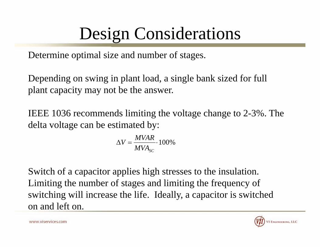
Design ConsiderationsDetermine optimal size and number of stages.
D di i i l t l d i l b k i d f f llDepending on swing in plant load, a single bank sized for full plant capacity may not be the answer.
IEEE 1036 recommends limiting the voltage change to 2-3%. The delta voltage can be estimated by:
MVAR
Switch of a capacitor applies high stresses to the insulation
%100SCMVA
MVARV
Switch of a capacitor applies high stresses to the insulation. Limiting the number of stages and limiting the frequency of switching will increase the life. Ideally, a capacitor is switched on and left on.

Design Considerations
Determine best location for the installation The most effectiveDetermine best location for the installation. The most effective placement for power factor correction capacitor banks is at the load. However, this is not always practical or cost effective.
Typically, a capacitor bank is installed on each bus of a main-tie-main switchgear.main switchgear.
If capacitors are installed at the motor pecker head (running capacitors) ensure that the capacitor VAR rating does not exceedcapacitors), ensure that the capacitor VAR rating does not exceed 90% of the motor no-load VAR. Otherwise, it is possible to damage the motor by overexcitation.

Design ConsiderationsUse caution when sizing motor running capacitors.
Logic would suggest that installation of a power factor correction capacitor at the motor terminals sized to provide unity power factor makes sense.y p
THIS IS NOT THE CASE. Do not exceed 90% of the motor no load kVAR demand Exceeding this value canmotor no-load kVAR demand. Exceeding this value can result in damage to the motor insulation as a result of overexcitation.
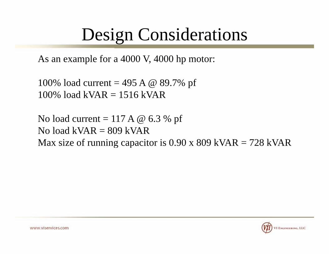
Design ConsiderationsAs an example for a 4000 V, 4000 hp motor:
100% load current = 495 A @ 89.7% pf100% load kVAR = 1516 kVAR
No load current = 117 A @ 6.3 % pfNo load kVAR = 809 kVARMax size of running capacitor is 0 90 x 809 kVAR = 728 kVARMax size of running capacitor is 0.90 x 809 kVAR = 728 kVAR

Design Considerations
M: Motor Magnetizing CurveM: Motor Magnetizing CurveC1: Capacitor size at 100% motor mag currentC2: Capacitor sized > 100% motor mag currentC4: Capacitor sized < 100% motor mag current
If the capacitive reactance of the capacitor is less less than that of the motor reactance (this occurs when to large of a capacitor is chosen). This combination of reactance will result in a resonant frequency below 60 hertz Therefore as the motor slows in speed the frequency of the motorfrequency below 60 hertz. Therefore, as the motor slows in speed, the frequency of the motor terminal voltage will decrease from a value of near 60 hertz toward zero. When the motor's terminal voltage frequency passes through the resonant frequency setup between the capacitor reactance and the motor reactance, the terminal voltage will become very high, only limited by the properties of the iron Depending on the inertia of the motor this resonance (or high voltage) may be present for airon. Depending on the inertia of the motor, this resonance (or high voltage) may be present for a considerable period of time.

Design Considerations
Determine the most optimal type of installationDetermine the most optimal type of installation.
Will the capacitor bank be installed within a fenced substation?Metal-enclosed, pad mount, or open rack may be good choices
Will the capacitor bank be installed in a process area?Will the capacitor bank be installed in a process area?Metal-enclosed or pad mount may be good choices
Will the capacitor bank be pole mounted on a distribution line?Will the capacitor bank be pole mounted on a distribution line?
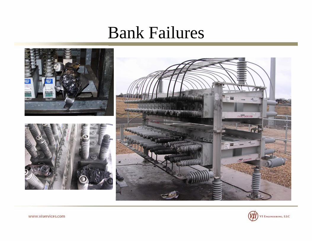
Bank Failures

Design Considerations
Consider the impact to personnel safety adjacent equipment when deciding between a metal-enclosed and open-rack system.
Porcelain can resemble shrapnel when a capacitor bushing fails.

Design ConsiderationsDetermine the most optimal configuration.
Higher reliability costs more.
2400 kVAR, 13800 V, wye-grounded (1) 800 kVAR per phase , , y g ( ) p pbank will be a smaller footprint and cost less than
2400 kVAR 13800 V wye ungrounded (8) 100 kVAR per2400 kVAR, 13800 V, wye-ungrounded (8) 100 kVAR per phase bank.
H h li bili f h d d b k iHowever, the reliability of the wye-ungrounded bank is significantly higher
Design ConsiderationsDetermine the switching equipment
When breakers are used for switching capacitors (single bank or back-to-back switching), the breakers must be rated for capacitor switching. p g
IEEE C37.99 provides the equations for calculating the inrush current and frequencycurrent and frequency.

Design Considerations

Design ConsiderationsConsider a single 4800 kVAR wye-ungrounded bank switched (with nominal inductance from equipment):
3253A pk @ 600 Hz, the product is 0.20 x 10⁷
Switching a second similar bank on the same bus without current limiting reactor:
24,058 A pk @ 7.66 kHz, the product is 18.4 x 10⁷
B ddi 100 H li i i h i h iBy adding a 100 mH current limiting reactor, the inrush is:
7254 A pk @ 2.31 kHz, the product is 1.7 x 10⁷p @ , p
Design Considerations

Design Considerations

Design ConsiderationsEnergization of a single capacitor bank.
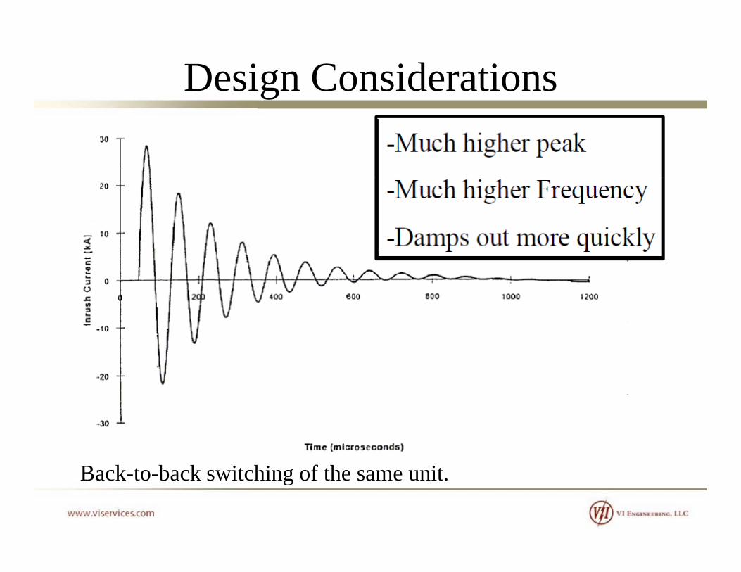
Design Considerations
B k b k i hi f h iBack-to-back switching of the same unit.
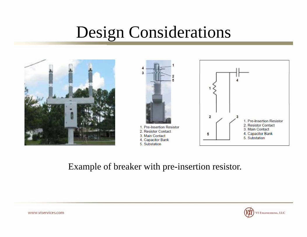
Design Considerations
E l f b k i h i i iExample of breaker with pre-insertion resistor.

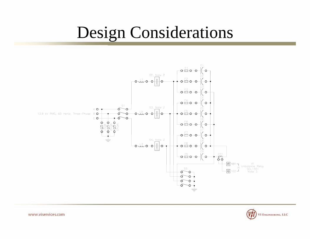
Design Considerations
Another application.Another application.
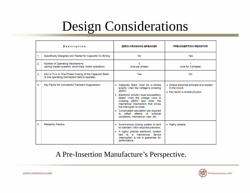
Design Considerations
A Pre-Insertion Manufacture’s Perspective.p

Design ConsiderationsAnother concern is voltage amplification as a result of switching a second capacitor bank.

Design Considerations

Design ConsiderationsConsider other accessories:
• Disconnect switch• Grounding switch• Kirk-key interlocky• Ventilation requirements• Control power

Design Considerations
Design Considerations

Design ConsiderationsBe aware that larger medium voltage motors may include surge packs.g p
The surge pack will decrease the crest voltage and rate of rise of the impending surge High rates of rise damage endrise of the impending surge. High rates of rise damage end turns while high crest voltage damage winding to core insulation.
Typically the capacitance of the is small enough that it can be neglected, but this should be verified.g

Design Considerations
Typical Surge Pack Application
Design Considerations
Do not confuse Harmonic Filter Banks with Power Factor Correction BanksCorrection Banks.
The voltage ratings of harmonic filter banks are substantially higher because they are connected on the back end of a tuning reactor where the voltage is substantially higher. As a result of the higher voltage, the installed kVAR can be anywhere from e g e vo ge, e s ed V c be yw e e o25% to 40% higher than nominal design.
The capacitor cans must be capable of this outputThe capacitor cans must be capable of this output.

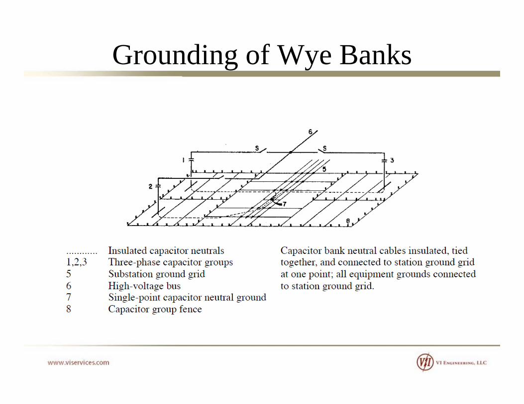
Grounding of Wye BanksIf multiple wye-grounded banks are in close proximity, use peninsula grounding or single-point grounding. p g g g p g g
Single-Point GroundingThe neutrals of all banks of a given voltage are connectedThe neutrals of all banks of a given voltage are connected together with insulated cable/bus and tied to the ground grid only at one point. This prevents high-frequency
(d b k b k i hi ) f fl i icurrents (due to back-to-back switching) from flowing into the ground grid.

Grounding of Wye BanksPeninsula GroundingOne or more isolated ground grid conductors are carried g gunderneath the capacitor rack of each phase and tied to the station ground grid at one point at the edge of the capacitor area All capacitor bank neutral connections are made toarea. All capacitor bank neutral connections are made to this isolated peninsula ground grid conductor.
Grounding of Wye Banks

Grounding of Wye Banks

References
• IEEE Std. 18• IEEE C37.99• NEMA CP-1• IEEE Std 1036•IEEE Std 399 (Brown Book)IEEE Std 399 (Brown Book)