car impact to pedestrian – fast 2d numerical analysis
TRANSCRIPT

Applied and Computational Mechanics 5 (2011) 151–162
Car impact to pedestrian – fast 2D numerical analysisL. Hyncıka,∗, H. Cechovaa
aNew Technologies – Research Centre, University of West Bohemia, Univerzitnı 8, 306 14 Plzen, Czech Republic
Received 9 March 2011; received in revised form 20 September 2011
Abstract
The paper concerns a modelling approach for fast 2D car to pedestrian impact analysis. The pedestrian model iscomposed using the Lagrange equations with multipliers. The model consists of rigid bodies defining the majorhuman body segments. The bodies are connected by rotational joints with non-linear response. The model isscalable based on the age and the gender. The car model is multi-segment composed as an open polygon. Betweenthe pedestrian and the car, there are contacts defined and modelled explicitly by force-penetration dependence. Fora given car profile design and a given human gender, age and percentile, the pedestrian impact consequences canbe evaluated quickly by means of virtual numerical analysis.c© 2011 University of West Bohemia. All rights reserved.
Keywords: contact, pedestrian, impact, multi-body numerical simulation
1. Introduction
The traffic accidents are within a group of external consequences causing the third highestnumber of death in the Czech Republic, just after deaths caused by falls and suicides [15]. Thenumbers of deaths or fatally injured citizens prove that the traffic accidents and their conse-quences are still a serious problem to be solved. The statistics show that the number of acci-dents decreases slowly in the past years [14]. However, the decrease is necessary to be speedup regarding also the socioeconomic aspects of the problem [4].
2. Motivation
A lot of effort is devoted to both passive and active safety systems development where virtualhuman body models start to play significant role since they become powerful tool for support-ing development of human-friendly and safe vehicles by the numerical way using computersimulation. Regarding that the correct biofidelic models are necessary to be developed and va-lidated [7]. However such complete models usually spend a lot of computational time. Havinga set of structural designs of a vehicle to be analysed, simple models are usually sufficient toolfor the first approximation. Based on the standard injury criteria implemented in the simplemodels, they might predict global human behaviour and injuries in very short computationaltime. Hence, a lot of structural designs and impact scenarios might be analysed quickly in orderto choose the best one for a deeper analysis.
3. Method
The paper shows the numerical modelling approach towards pedestrian impact analysis. Cur-rently, two-dimensional (2D) modelling approach is presented.
∗Corresponding author. Tel.: +420 377 634 709, e-mail: [email protected].
151
L. Hyncık et al. / Applied and Computational Mechanics 5 (2011) 151–162
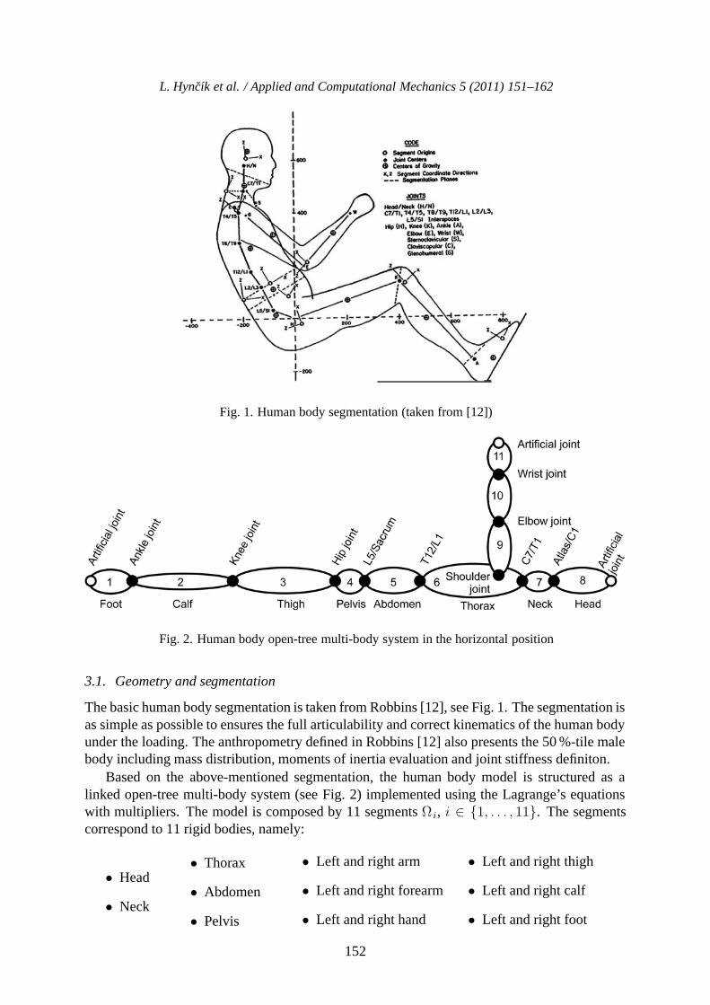
Fig. 1. Human body segmentation (taken from [12])
Fig. 2. Human body open-tree multi-body system in the horizontal position
3.1. Geometry and segmentation
The basic human body segmentation is taken from Robbins [12], see Fig. 1. The segmentation isas simple as possible to ensures the full articulability and correct kinematics of the human bodyunder the loading. The anthropometry defined in Robbins [12] also presents the 50 %-tile malebody including mass distribution, moments of inertia evaluation and joint stiffness definiton.
Based on the above-mentioned segmentation, the human body model is structured as alinked open-tree multi-body system (see Fig. 2) implemented using the Lagrange’s equationswith multipliers. The model is composed by 11 segments Ω i, i ∈ {1, . . . , 11}. The segmentscorrespond to 11 rigid bodies, namely:
• Head
• Neck
• Thorax
• Abdomen
• Pelvis
• Left and right arm
• Left and right forearm
• Left and right hand
• Left and right thigh
• Left and right calf
• Left and right foot
152

L. Hyncık et al. / Applied and Computational Mechanics 5 (2011) 151–162
Due to the planar (2D) approach, the couple segments (arm, forearm, hand, thigh, calf andfoot) are considered as a one single segment.
3.2. Mass distribuion and joints
The position of each segment is geometrically defined by the centre Si, i ∈ {1, . . . , 11} locatedbetween 2 joints Ki,i−1 and Ki,i+1 connecting the segment to the previous and the followingsegment in the tree system. The exception is for the head, the hand and the foot that are theouter segments. In this case, an artificial joint supplying the missing second joint is defined forthe segment length measuring purposes. The segment centre
Si =Ki,i−1 +Ki,i+1
2(1)
is an origin of the particular segment local coordinate system. The first local coordinate systemaxis is defined as
e1 =Ki,i+1 − Si
‖Ki,i+1 − Si‖(2)
and the second one e2 is a unit vector perpendicular e1 constructing a clock-wise system. Eachsegment carries its mass mi and moment of inertia Ii, i ∈ {1, . . . , 11} concentrated to its centreof gravity Ti =
[T xi,
T yi], i ∈ {1, . . . , 11} where the bar denotes coordinates in the segment
local coordinate system (e1, e2). The scheme is shown in Fig. 3.
Fig. 3. Segment definition
Two neighbouring segments are connected by joints. The full model accommodates 10joints, namely:
• Head/neck joint in the position between vertebrae Atlas bone and C1
• Neck/thorax in the position between vertebrae C7 and T1
• Thorax/abdomen in the position between vertebrae T12 and L1
• Abdomen/pelvis in the position between vertebrae L5 and Sacrum bone
• Left and right shoulder
• Left and right elbow
• Left and right wrist
• Left and right hip
• Left and right knee
• Left and right ankle
153

L. Hyncık et al. / Applied and Computational Mechanics 5 (2011) 151–162
With respect to the Robbins segmentation [12], all joints in the current model are modelledas rotational ones accommodating non-linear rotational stiffness. Due to the planar approach,the couple joints (shoulder, elbow, wrist, hip knee and ankle) are concentrated into one singlejoint having double stiffness.
3.3. Anthropometry and stiffness scaling
The basic 50 %-tile human body anthropometry and mass distribution is based on [12] (for bothmale and female). The details of the scaling can be found in [8]. Due to the simple modellingapproach and no detailed segment shape description, only the height based scaling is concerned.Blaha [2] defines the height from ground of all the above-mentioned joints in the human uprightstanding position, so the particular segment height can be obtained by substraction. The datameasured by Blaha [2] depends on gender and age from 0 till 75 years.
Let us define a length vector li = Ki,i+1 − Ki,i−1 for each segment Ωi, i ∈ {1, . . . , 11}.Concerning the size, each segment can be defined by its length 2ai = ‖li‖ as the distancebetween the joints connecting the segment to the previous and the following segment in the treesystem. Considering the upright standing position of the model, each segment height can bedefined as hi = lie2 in the global coordinate system (e1, e2). The upright standing position ofRobbins [12] is defined in [8].
Mathematically the anthropometry scaling means that the original size is multiplied by ascaling factor ki defined as a ratio between the target height defined by [2] and the originalheight hi of the segment in the upright standing positon. Concerning the head, the hand and thefoot that are the outer segments the length is measured with help of the artificial joint definedabove. In summary considering the uniform mass density distribution and the model uprightstanding position, the 3 basic points defining any segment (centre of gravity and both joints)can be scaled by multiplying by the scaling coeffitient ki in the global coordinate system asx = kix. After the anthropometry scaling, all segments have to be reconnected in the jointpositions. The mass and the moment of inertia of a particular segment change by changing itssize. Considering the uniform mass density distribution, the mass and moment of inertia of eachsegment can be scaled as m = k3
im and I = k5i I [8], where m and I denotes the scaled values.
The segments are linked together using the rotational joints with non-linear stiffnesses de-fined in [12] for a 50 %-tile (average) subject. The joints flexibility also changes due to the age.The age dependent flexibility is also scaled based on so called flexindex [1]. Flexindex definesthe flexibility of the whole human body by a single number (percentage to the average state)taking into account the flexibility of all major joints together [1]. The percentage is taken intoaccount to multiply the all body joint ranges for the desired age.
3.4. Multi-body approach
Let us have the model structure described by rigid segments linked to an open-tree multi-bodysystem as displayed in Fig. 3. The human model dynamical response due to the impact loadingis investigated by the energy balance approach using the Lagrange’s equations with multipliers.Let us have n segments, in our case n = 11, having the segment numbered by i ∈ {1, . . . , 8}from the foot through the tree system uptill the head and by i ∈ {6, 9, 10, 11} from the thoraxthrough the tree system uptill the hand. The motion of each segment Ωi, i ∈ {1, . . . , n} isdefined in plane by 3 independent coordinates where the first two defines the planar position ofits centre of gravity and the third one the rotation around it. Let us define the vector
154

L. Hyncık et al. / Applied and Computational Mechanics 5 (2011) 151–162
q = [x1, . . . , xn, y1, . . . , yn, ϕ1 . . . , ϕn]T (3)
including 33 generalized coordinates that are dependent by m = 2(n− 1) = 20 constraints
Φi = −xi + xi+1 − (ai − xi)cos(ϕi) (4)
−(ai+1 + xi+1)cos(ϕi+1)− yisin(ϕi) + yi+1sin(ϕi+1), (5)
Φn−1+i = −yi + yi+1 − (ai − xi)sin(ϕi) (6)
−(ai+1 + xi+1)sin(ϕi+1) + yicos(ϕi)− yi+1cos(ϕi+1), (7)
where xi and yi are the coordinates of the segment centre of gravity in the local coordinatesystem (see Fig. 3) and i ∈ {1, . . . , 7} from the ankle over the legs and spine to the head/neckjoint,
Φ8 = = −x6 + x9 − (xshoulder − x6)cos(ϕ6) (8)
−(a9 + x9)cos(ϕ9)− y6sin(ϕ6) + (yshoulder + y9)sin(ϕ9), (9)
Φ18 = = −x6 + x9 − (xshoulder − x6)sin(ϕ6) (10)
−(a9 + x9)sin(ϕ9) + (y6 − yshoulder)cos(ϕ6)− y9cos(ϕ9), (11)
for the shoulder joint where [xshoulder, yshoulder]T are the coordinates of the shoulder joint in the
thorax local coordinate system and
Φi = −xi + xi+1 − (ai − xi)cos(ϕi) (12)
−(ai+1 + xi+1)cos(ϕi+1)− yisin(ϕi) + yi+1sin(ϕi+1), (13)
Φn−1+i = −yi + yi+1 − (ai − xi)sin(ϕi) (14)
−(ai+1 + xi+1)sin(ϕi+1) + yicos(ϕi)− yi+1cos(ϕi+1), (15)
where i ∈ {9, 10} for the elbow and the wrist joints. The constraints link together the centres ofgravity of all neighbouring couples of segments. So the whole system has 3n−m = 33− 20 =13 degrees of freedom that are the initial position and rotation of the base body and 10 furtherrelative rotations of the open-tree linked system of rigid bodies. The system of equations isconservative and the kinetic and the potential energies have the forms
Ek =1
2
n∑i=1
mi
(xi
2 + yi2)+
1
2
n∑i=1
Iiϕi2, (16)
Ep = g
n∑i=1
miyi +1
2
∑(i,j)
kij (ϕij)ϕ2ij , (17)
where the limits (i, j) in the second term of the potential energy mean all segment couplesconnected by joints, kij is the particular relative rotation dependent joint rotational stiffnes andϕij = ϕj − ϕi is the relative rotation of the two neighbouring segments. Considering theLagrange’s equations with multipliers have the form
d
dt
(∂L
∂qi
)− ∂L
∂qi=
m∑j=1
λj∂fj∂qi
, i ∈ {1, . . . , 3n} (18)
155

L. Hyncık et al. / Applied and Computational Mechanics 5 (2011) 151–162
with the Lagrange’s function L = Ek − Ep, we have the equations of motion in the form
d
dt
(∂Ek
∂qi
)+
∂Ep
∂qi=
m∑j=1
λj∂fj∂qi
i ∈ {1, . . . , 3n} . (19)
Equations (18) can be rewritten using the matrix notation as[M ΦT
q
Φq O
] [q−λ
]=
[rγ
], (20)
where M is the mass matrix, Φq is the matrix of constraint derivatives, O is the correspondingzero matrix, r is the external load matrix and γ is the matrix consisting of the rest after theconstraint derivatives.
3.5. Contact definition
The model is defined by a linked open-tree multi-body system skeleton carrying the mass. Forthe purposes of pedestrian impact analysis, the contact forces play an important load. The con-tact forces express loading caused by the vehicle impact to the pedestrian. In order to modelthe contact well, each body of the multi-body system has to accommodate an external shape ofthe particular body segment. An ellipse attached to each segment is a good estimation for ourpurpose. Each segment ellipse is located by its centre to the segment centre (that is not neces-sarily its centre of gravity) and it is described by 2 semi-axes ai and bi as shown in Fig. 3. Thescaling of the segment depth in the direction of the second semi-axis can be simply computedas bi = kibi. The vehicle model is based on the approximation by rigid open polygon describingmajor vehicle frontal parts (bumper, bonnet and windshield) [10].
3.5.1. Collision detection
The shape of each segment Ωi, i ∈ {1, . . . , n} is geometrically defined by an ellipse. Consider-ing homogeneous coordinates X = [x, y, w]T , the ellipse can be written in the form
XTAX = 0 . (21)
Any ellipse with the semi-axes ai and bi parallel to the global coordinate system axes hasthe matrix in the form
Ai =
⎡⎢⎣
1a2i
0 0
0 1b2i
0
0 0 −1
⎤⎥⎦ i ∈ {1, . . . , 11} . (22)
The segments of the human body models are positioned and angled in the plane by theirgeneralized coordinates [xi, yi, ϕi]
T , i ∈ {1, . . . , n} that can define transformation matrix Ri,i ∈ {1, . . . , 11} that transforms (rotates and moves) the basic ellipse (22) to the particularposition defined by [xi, yi, ϕi]
T in the plane. Such positioned ellipse can be written in the form
Ai = RTi AiRi, i ∈ {1, . . . , n} . (23)
The vehicle model is composed of s straight lines. Any segment Ωi, i ∈ {1, . . . , n} definedgeometrically by the particular ellipse defined by (23) can come into collision with one or morelines from the open polygon
X = Pl + (Ql − Pl)t , l ∈ {1, . . . , s} , t ∈ [0, 1] (24)
156

L. Hyncık et al. / Applied and Computational Mechanics 5 (2011) 151–162
Fig. 4. Collision detection with contact force identification
that leads to a quadratic equation. Negative discriminant means no collision, zero or positivediscriminant means contact or penetration.
Talking about contacts in multi-body dynamics, the energy absorption must be implementedin the internal contact variables since the rigidity of the contacting bodies. Furthermore, correctcontact modelling in multi-body approach to biomechanics is crucial due to the high defor-mation of biological materials. Based on literature review, the continuous contact model, alsoreferred to as compliant contact model, is chosen [5]. The basis of the continuous contact modelis to measure the penetration of the contacting bodies, see Fig. 4a. This is done by defining thenormal contact force Fn as an explicit function of local penetration δ and its rate as
Fn = Fn
(δ, δ
). (25)
For the total contact force, the simplified nonlinear spring-dashpot contact force model in-cluding tangential friction is used in the current paper as
Fc =[Fn (δ)− bδ
](n− ft) , (26)
where n and t are the penetration normal and tangent vectors respectively, f is the frictioncoefficient. The force on penetration dependance for various vehicle parts is take from [10]. Thepenetratration depth is checked couple by couple (segment k to open polygon line l, see Fig. 4cover the whole human body and over the whole open polygon and the particular penetrationdepth is computed as the distance between the vehicle structure open polygon line l and theparallel line tangent to the ellipse surface l′. Mathematically the line parallel to the open polygonline is constructed as the general line l′ tangent to the ellipse with the tangent vector |PlQl|.There are 2 solutions for such task, so it is necessary to choose the solution l ′ that is closer tothe line |PlQl| otherwise the situation appeared on the ellipse opposite side. Introducing theline l′, the contact point Ck is also detected. The contact force point of action (here line ofaction since all forces of the same value applied on a line to a rigid body have the same action)is the intersection of the vehicle structure open polygon line l and the perpendicular line goingthrough the tangent point of contact p. Let us denote the intersection between lines p and l asthe bottom point Bl. The force action line is constructed as the line p perpendicular to the line|PlQl| going through the contact point Ck.
In several cases, an edge contact might happen, see Fig. 4b. If there is the edge contact (seeFig. 4b and Fig. 4c) and the bottom point Bl is introduced outside the open polygon line (t falloutside the interval [0, 1], see Fig. 4b), the bottom point comes to the edge point Q l where thepenetration is currently highest. The force action line becomes then p′.
157

L. Hyncık et al. / Applied and Computational Mechanics 5 (2011) 151–162
If the segment k is in contact with more open polygon lines (e.g. l1 and l2, see Fig. 4c),all contacts are treated separately and separate contact forces Fc1 and Fc2 act on the particularsegment. There is no reaction on the vehicle considering its higher mass. Concerning the par-ticular segment k, the forces Fci, i ∈ {1, . . . , s} are translated to its centre of gravity includinga moment caused by translation. The contact forces acting from the i ∈ {1, . . . , s} contact pairson segment k is decomposed to the global coordinate system axis and togehter with the momentappears then in the right hand side vector r in (20) as
r =
⎡⎢⎢⎢⎢⎢⎢⎢⎢⎢⎢⎢⎢⎢⎢⎢⎢⎢⎣
...l∑
i=1
Fckle1
...
mkg +l∑
i=1
Fckle2
...l∑
i=1
Mkl
...
⎤⎥⎥⎥⎥⎥⎥⎥⎥⎥⎥⎥⎥⎥⎥⎥⎥⎥⎦
. (27)
4. Results
Numerically, the complete simulation model is implemented and solved in the form
[M ΦT
q
Φq O
] [q−λ
]=
[rγ
](28)
that leads to the system of 33 second order non-linear ordinary differential equations
q = M−1[r +ΦT
q
(ΦqM
−1ΦTq
)−1 (γ −ΦqM
−1r)]
, (29)
where r is the right hand side including also the first order derivative expressions. The Baum-gart’s stabilization [6] for better convergence is used to stabilize the system. It leads to the finalform of the solution as
q = M−1[r +ΦT
q
(ΦqM
−1ΦTq
)−1(γ − αΦ− β2Φ−ΦqM
−1r)]
, (30)
where α and β are the Baumgart’s stabilization constants. The system is numerically solvedin MATLAB R2010a [11] computational environment using especially the ode45 function fornumerical integration and the fzero function for the contact point detection. Other mathematicaloperations concern standard matrix manipulation.
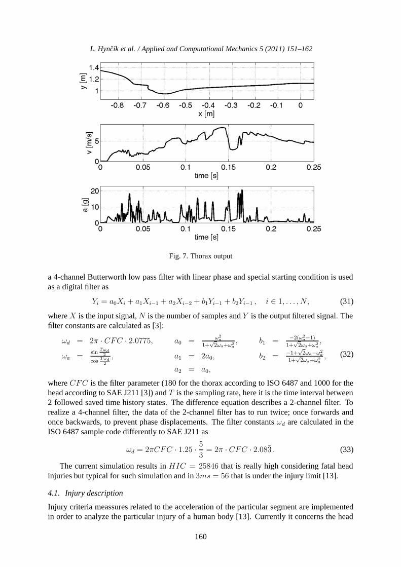
Fig. 5 shows a typical pedestrian kinematic state of the impact situation at time 75 ms af-ter the impact in the developed software [9]. The impact takes into account a 5 %-tile femalepedestrian impacted by the standard passengers’ car defined by Kerrigan [10] with car initialvelocity 30 km/h. Fig. 6 shows the head output, namely relative head to car position in plane,head velocity and head acceleration. The same output is stated in Fig. 7 for thorax. The accel-erations are filtered by the Channel Frequency Class (CFC) [3]. In accordance with SAE J211,
158

L. Hyncık et al. / Applied and Computational Mechanics 5 (2011) 151–162
Fig. 5. Kinematic state
Fig. 6. Head output
159
L. Hyncık et al. / Applied and Computational Mechanics 5 (2011) 151–162
Fig. 7. Thorax output
a 4-channel Butterworth low pass filter with linear phase and special starting condition is usedas a digital filter as
Yi = a0Xi + a1Xi−1 + a2Xi−2 + b1Yi−1 + b2Yi−1 , i ∈ 1, . . . , N, (31)
where X is the input signal, N is the number of samples and Y is the output filtered signal. Thefilter constants are calculated as [3]:
ωd = 2π · CFC · 2.0775, a0 = ω2a
1+√2ωa+ω2
a, b1 = −2(ω2
a−1)
1+√2ωa+ω2
a,
ωa =sin
Tωd2
cosTωd2
, a1 = 2a0, b2 = −1+√2ωa−ω2
a
1+√2ωa+ω2
a,
a2 = a0,
(32)
where CFC is the filter parameter (180 for the thorax according to ISO 6487 and 1000 for thehead according to SAE J211 [3]) and T is the sampling rate, here it is the time interval between2 followed saved time history states. The difference equation describes a 2-channel filter. Torealize a 4-channel filter, the data of the 2-channel filter has to run twice; once forwards andonce backwards, to prevent phase displacements. The filter constants ωd are calculated in theISO 6487 sample code differently to SAE J211 as
ωd = 2πCFC · 1.25 · 53= 2π · CFC · 2.083 . (33)
The current simulation results in HIC = 25846 that is really high considering fatal headinjuries but typical for such simulation and in 3ms = 56 that is under the injury limit [13].
4.1. Injury description
Injury criteria meassures related to the acceleration of the particular segment are implementedin order to analyze the particular injury of a human body [13]. Currently it concerns the head
160

L. Hyncık et al. / Applied and Computational Mechanics 5 (2011) 151–162
injury criterion (HIC) and thethorax injury criterion (3ms). Whilst the 3ms criterion is thehighest thorax acceleration lasting at least 3 miliseconds, the head injury criterion is stated asthe integral
HIC = max0≤t1≤t2≤T
(1
t2 − t1
∫ t2
t1
ahead(t)dt
)2.5
(t2 − t1), (34)
where ahead(t) is the head centre of gravity acceleration during the loading, t2 and t1 are twoarbitrary times during the acceleration pulse. Time values are to be provided in seconds. Forexample, the victim of an accident sustains a head injury if HIC36 < 1 000, where the timewindow is t2 − t1 ≤ 36 ms.
5. Discussion
The above-mentioned study employs the standard multi-body system modelling approach forthe used in biomechanics, especially the impact biomechanics. The main advantage of themulti-body system approach is the computation speed. The pedestrian impact scenario takesusually considerable time comparing to the standards crash simulation since the global kine-matics of the pedestrian due to the free space after the impact. Hence the fast computation ofthe global kinematics including basic injury description is profitable. Such simulation can befollowed by a deeper injury analysis e.g. by detailed finite element models whose have muchhigher requirements on computational time. Moreover, merging the multi-body system ap-proach with some deformable elements like flexible joints, continuous contact models or evenfinite element parts ensure even wider exploitation of the model in the field of safety systemdevelopment. The current study shows the planar approach that can be simply extended to thefull 3D spatial modelling. The multi-body skeleton of the model can also carry realistic humanshapes modelled by finite elements surfaces.
6. Conclusion
The paper shows a multi-body approach towards modelling of the human body response causedby the external impact loading. The human body is segmented into 11 major parts that com-pose together an open-tree linked multi-body structure. Particular neighbouring segments areconnected by rotatinal joints with non-linear stiffness. Each segment carries a mass and inertialproperties and its shape is simplified by an ellipse in order to simulate a contact surface. Contin-uous contact model based on penetration dependent contact force for each penetrating segmentcouples is implemented in order to asure correct impact loading due to the external contact.Age scaling concerning anthropometry, mass distribution and joint flexibility is derived. Injurycriteria meassures are implemented in order to analyze the particular injury of a human body.The model serves for fast analysis of a frontal pedestrian impact that might go before a detailedanalysis using more complex virtual human body models or physical tests with dummies. The2D approach seems to be a promising fast tool for simple analysis even including multiple bodycontact.
Acknowledgements
The work is supported by the project CG911-044-150 of the Czech Ministry of Transport.
161

L. Hyncık et al. / Applied and Computational Mechanics 5 (2011) 151–162
References
[1] Araujo, C. G., Flexibility assessment: normative values for flexitest from 5 to 91 years of age.Arq. Bras. Cardiol., 90 (2008) 257–263.
[2] Blaha, P., et al., Anthropometry of the Czechoslovak population from 6 till 55 years, Czechoslovakspartakiade. 1985 (in Czech).
[3] Cichos, D., de Vogel, D., Otto, M., Schaar, O., Zolsch, S., Crash Analysis Criteria Description.2006.
[4] Dankova, A., Economical aspect of traffic accidents. Traffic engineering, 2007 (in Czech).[5] Gilardi, G., Sharf, I., Literature survey of contact dynamics modelling. Mechanism and Machine
Theory, 37 (2002) 1 213–1 239.[6] Hajzman, M., Polach, P., Application of stabilization techniques in the dynamic analysis of multi-
body systems. Applied and Computational Mechanics, 1 (2007) 479–488.[7] Haug, E., Choi, H. Y., Robin, S., Beaugonin, M., Human models for Crash and impact simulation.
Elsevier, North Holland, 2004.[8] Hyncık, L., Novacek, V., Blaha, P., Chvojka, O., Krejcı, P., On scaling of human body models.
Applied and Computational Mechanics, 1 (2007) 63–76.[9] Hyncık, L., Cechova, H., Antroped2D: Software for 2d car to pedestrian frontal impact analysis.
[10] Kerrigan, J. R., Murphy, D. B., Drinkwater, D. C., Kam, C. Y., Bose, D., Crandall, J. R., Kinematiccorridors for pmhs tested in full-scale pedestrian impact. University of Virginia Center for AppliedBoimechanics, 2005.
[11] MathWorks, MATLAB R2010a.[12] Robbins, D. H., Anthropometry of motor vehicle occupants. Technical report, 1983.[13] Schmitt, K. U., Niederer, P., Walz, F., Trauma biomechanics, Introduction to accidental injury.
Springer-Verlag, 2004.[14] Skacal, L., Deep analysis of international comparison of traffic accidents in the Czech Republic.
Transport Research Centre Brno, 2007 (in Czech).[15] Czech Statistical Office, External death causes in the Czech Republic in years from 1994 till 2006
(in Czech).
162