car make and model recognition using 3d curve …ehsiao/ehsiao_wacv14.pdfcar make and model...
TRANSCRIPT

Car Make and Model Recognition using 3D Curve Alignment
Krishnan Ramnath, Sudipta N. Sinha, Richard SzeliskiMicrosoft Research
{kramnath,sudipsin,szeliski}@microsoft.com
Edward HsiaoCarnegie Mellon University
Abstract
We present a new approach for recognizing the makeand model of a car from a single image. While most pre-vious methods are restricted to fixed or limited viewpoints,our system is able to verify a car’s make and model froman arbitrary view. Our model consists of 3D space curvesobtained by backprojecting image curves onto silhouette-based visual hulls and then refining them using three-viewcurve matching. These 3D curves are then matched to 2Dimage curves using a 3D view-based alignment technique.We present two different methods for estimating the pose ofa car, which we then use to initialize the 3D curve matching.Our approach is able to verify the exact make and model ofa car over a wide range of viewpoints in cluttered scenes.
1. IntroductionRecognizing the exact make, model, and year of a car
from an arbitrary viewpoint is something that car aficiona-dos do with relative ease. To date, however, no computervision system can mimic this ability over a wide range ofviewpoints. Why is this so?
At first glance, car recognition should be readily solv-able, since it is an example of instance recognition, wherewe can build or obtain high-quality 3D models or largenumbers of reference images. However, cars are more chal-lenging than many other man-made objects, since they havelarge untextured regions and their appearance is often dom-inated by highlight lines and environmental reflections. Thequestion we address is therefore: is car recognition an eas-ily solvable example of fine-grained subordinate categoryrecognition [6, 7] or an extremely challenging vision prob-lem due to the complexity and variability in appearance?
To date, most of the work in recognizing the exact makeand model of a car involves only a single viewpoint or lim-ited viewpoint change [24, 4, 23]. In parallel, work ongeneral object category detection and recognition is start-ing to simultaneously recognize the rough pose of the ob-ject [30, 28, 21, 17, 8]. Our paper aims to unify these twoapproaches, by developing a system than can handle an arbi-
Figure 1. Steps in constructing our 3D car model for a 2011 HondaCivic Sedan: (top) three of the images used to generate the visualhull; (middle) the visual hull; (bottom) 3D space curves projectedonto the visual hull.
trary viewpoint while also determining the exact make andmodel of a vehicle. While our main focus is on the verifica-tion stage, i.e., determining the exact model given a roughinitial pose estimate for the car, we also present two differ-ent pose estimation (automatic initialization) methods, onethat is an extension of a previous technique [31] and one wedevelop in this paper.
In the following, we describe our processing pipelineand matching algorithms for solving this problem. We be-gin with a review of related work in this field. We followthis with an overview of the problem and justify our choiceof view-based 3D curve models as the basic representationused in our system. We then describe the steps for automaticreconstruction of these 3D curve models from training im-ages (Sections 3.2 and 3.3). We then show how our modelscan be rigidly aligned to novel test images using oriented3D chamfer matching to perform simultaneous pose andmake/model recognition (Section 4). Section 5 describeshow we combine our chamfer matching scores to performclassification using logistic regression. Section 6 describestwo different techniques for estimating the initial pose ofthe car, which enables the system to be fully automatic, al-beit at a reduced performance rate. Finally, we present ourexperimental results on eight different car models and closewith a discussion of our results and ideas for future work.

2. Previous work
3D object recognition is a fundamental problem in com-puter vision, with a long history dating back to the late1960s. Hoiem and Savarese [9] present a nice survey onthis topic and a comprehensive list of the large number ofpapers published in this area.
Some of the early techniques were based on the conceptof 3D alignment between 3D curve models and 2D imageedges [12]. However, these techniques fell out of favor,since they required strong curvilinear features and were re-placed by view-based techniques which used interest pointor region detectors and descriptors [30, 28].
Work in detecting cars, often from fixed viewpoints suchas side views, has been evolving in parallel [25] and hasbecome, along with detecting people, bicycles, and otherobjects, a central component of the PASCAL VOC (VisualObject Category) challenge [5].
More recently, researchers have started to combine ob-ject detection with pose estimation. For example, Ozuysalet al. [21] use an initial bounding box of a car to select aview-specific classifier to refine the hypothesis, while Glas-ner et al. [8] vote for potential pose parameters and thenrefine these using view-specific SVMs. Li et al. [17] learnthe appearance of features located at key points (wheels,corners) of a car and use an elastic shape model to detectboth the location and pose of cars in street images.
While most of these techniques are based on traditionalfeature detectors and descriptors, a parallel line of workuses contour-based recognition and pose estimation. Shot-ton et al. [26] use a star-shaped model of object contoursand introduce oriented chamfer matching, where the orien-tations of the edges are taken into account when measuringtheir correspondence distance. (More recent work on ori-ented chamfer matching includes [18].) Lu et al. [20] ex-tract edgels and link them to form contours, which are thengrouped into part bundles and matched using shape con-text similarity [1]. Leotta and Mundy [15] build a 3D de-formable vehicle model and show good edge-based fittingresults on images. Most recently, Payet and Todorovic [22]use view-based shape templates and a bag of boundariesrepresentation placed on a deformable 2D grid and showgood results on boundary detection and pose estimation.
To date, most of the work on recognizing specific carmodels has been limited to fixed viewpoints, e.g., front orrear views of cars [4, 23]. A notable exception is the recentpaper of Jang and Turk [13], which uses SURF features anda quantized bag of words approach to recognize toy modelcars shot against a uniform background. Our work extendsthe domain of applicability to cluttered real-world sceneswith strong reflections and demonstrates that curve-basedrecognition can be more accurate than existing methods.
3. 3D Curve ModelsIn our technique, each car model is represented by a set
of non-parametric 3D curves. We reconstruct these curvesfrom natural images rather than from CAD models, sinceimage-based modeling approaches generate 3D curves thatare more likely to match 2D curves detected in test imagestaken “in the wild”. In this section, we present our approachfor reconstructing these 3D curve models and matchingthese models to new test images.
Instead of using a single global 3D model, we use a view-based representation consisting of separate view-dependentpartial 3D curve models, where each model is associatedwith the viewpoint corresponding to each of the trainingimages. In order to align the 3D curve model to a new testimage, we find the closest training image and then alignthe corresponding partial 3D curve model to the edges inthe test image by estimating a rigid 3D perspective imagetransformation. This has the advantage that subtle view-dependent features can be modeled, and the visibility of thecurves is handled naturally.
Curve matching could be performed using pure 2D align-ment and chamfer matching [26, 18]. However, even withnon-rigid alignment techniques such as Active Shape Mod-els (ASMs) [3, 16], the large variation in the curve renderedfrom an arbitrary camera viewpoint make it difficult to si-multaneously recover a good registration between the 3Dmodel and the test image while still discerning the subtleshape differences that differentiate one car model from an-other (Section 7). Since Active Shape Models will in gen-eral not reflect the true 3D transformation of a rigid 3D carmodel, a better approach is to directly use a 3D model.
3.1. Formulation
We represent the 3D curves in each view of the 3D carmodel by a set of NM 3D point samples Pi. The goal ofalignment (Section 4) is to recover the unknown camerapose or viewing transformation M = K[R|t] of the 3Dmodel that minimizes the sum of reprojection errors be-tween the NM projected 3D model points and their corre-sponding nearest 2D edge points or edgels, amongst theNT
edgels in the test image denoted as {pk}. The optimal trans-formation M∗ is the one that minimizes
Dc =1
NM
NM∑i=1
minkd(pk,PMPi), (1)
where d(p, q) is one of the 2D distance metrics discussed inSection 4. The operator P projects 3D points into the testimage, and the minimum distance over the edgels {pk} canbe efficiently computed using a distance transform [11].1
1This is often called chamfer matching since the distance transformresembles the chamfers used as guides in manufacturing processes.

The most common method for obtaining 3D shape fromcalibrated images is to first recover pixel correspondencesacross images captured from multiple viewpoints and thenperform multi-view triangulation. However, for curves,directly computing reliable pixel-to-pixel correspondencefrom adjacent images is a challenging problem. For thisreason, we first build a visual hull model (Section 3.2), andthen use this geometry as the initial basis for our 3D curvelocations, which we then further refine using robust three-view stereo matching (Section 3.3).
3.2. Visual Hull Reconstruction
Our input data consists of multiple turntable images ofeach car model taken at regular angular intervals against aclean background (Figure 1). Such images are often avail-able on manufacturers’ web sites, and in a production sys-tem, would be captured with carefully calibrated cameras.Since in our case we did not have access to the intrinsiccamera parameters, we automatically detect the ellipses cor-responding to the wheels (Section 6.2) in the subset of im-ages where these could be reliably detected and use the van-ishing points defined by the ellipse bitangents to estimateboth the focal length and optic center of each camera in asequence.
For each calibrated sequence, we obtain our initial 3Dcurves by backprojecting the 2D image curves onto anautomatically generated visual hull reconstruction of thecar [14]. We extract binary silhouettes from each input im-age using thresholding followed by appropriate morpholog-ical operations. Next, we build a volumetric 3D model byintersecting the backprojected silhouette cones in 3D, andfinally project this model into each image to obtain an as-sociated depth map. Since all cameras are calibrated, any2D point p in an image with a valid depth estimate can bemapped to a 3D point P on the visual hull. Using this tech-nique, we map a set of 2D points constituting a 2D curvein the image to obtain an initial estimate of the correspond-ing 3D curve. These curves are assumed to be visible fromviewpoints near the original camera viewpoint.
As an alternative to our approach, in order to handle carimages with textured backgrounds, one could use structurefrom motion to reconstruct the full scene and then automat-ically segment the car using the method proposed in [8].
3.3. Model Refinement
Edges seen on cars can arise from specular reflections inthe scene. The resulting spurious curves in the 3D curvemodel can corrupt the 3D chamfer matching score and needto be removed for robustness. We filter these spurious edgesbased on the observation that given multiple viewpoints, the3D position of points on these curves inferred from the 3Dmodel are not consistent across different views (Figure 2b).
To detect spurious edges for a reference view, we con-
(a) (b) (c)
Figure 2. Curve Refinement: (a) original curves; (b) curves fromneighboring views reprojected into current view; (c) the subset ofcurves with depths consistent in three views.
sider its left and right neighboring views in the input se-quence. Each 3D point on a curve is projected into theneighboring views to test whether the projected point lieswithin τd pixels of an edge point on the correspondingepipolar line in the respective image. Points that have validmatches in both neighboring views are retained.
For each retained point, given the two points matchedon corresponding epipolar lines in the neighboring views,we use the Direct Linear Transform [29], i.e. linear trian-gulation to re-estimate the position of the 3D point. Thisrefinement is performed for all 3D points on all 3D curvesin every viewpoint of the model . An example of the refinedmodel is shown in Figure 2c.
4. 3D Chamfer Matching
Once we have built our 3D view-based curve models, wecan use these to recognize the car make and model of a newtest image. For each model, we estimate the transforma-tion M = K[R|t] that minimizes the sum of reprojectionerrors Dc given in equation (1) between the NM projected3D points of the model, PMPi, and the NT 2D points inthe image, {pk}.
To avoid an expensive search over all possible modelposes and positions, we would like to efficiently recover theinitial pose of the car using a pose estimation approach. Anumber of such techniques have been developed [21, 31].In Section 6 we describe a novel technique for automaticinitialization of the model pose and in Section 7.1 we showevaluation results using this technique in comparison withhand initialized poses.
Given an initial pose estimate, we refine it using cham-fer matching by minimizing (1) using the Levenberg-Marquardt non-linear least squares algorithm. To updatethe parameters controlling the camera projection matrix M ,we compute the Jacobian J for our camera parameters. Werepresent the camera rotation by the axis-angle representa-tion ω = θn̂ = (ωx, ωy, ωz) and the camera position bythe camera center c = (cx, cy, cz). We also allow the focallength f to vary and assume that the principal point (ox, oy)is at the center of each test image. The camera parametervector is thus specified by γ = (ωx, ωy, ωz, cx, cy, cz, f).Details for how the Levenberg-Marquardt algorithm can beused to perform this alignment can be found in [29, §6.2.2].Figure 3 shows an example of the initial manual align-
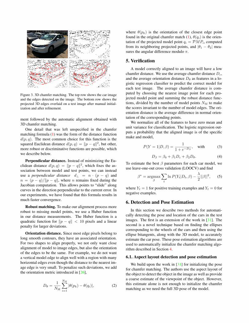
Figure 3. 3D chamfer matching. The top row shows the car imageand the edges detected on the image. The bottom row shows theprojected 3D edges overlaid on a test image after manual initial-ization and after refinement.
ment followed by the automatic alignment obtained with3D chamfer matching.
One detail that was left unspecified in the chamfermatching formula (1) was the form of the distance functiond(p, q). The most common choice for this function is thesquared Euclidean distance d(p, q) = ‖p − q‖2, but other,more robust or discriminative functions are possible, whichwe describe below.
Perpendicular distance. Instead of minimizing the Eu-clidean distance d(p, q) = ‖p − q‖2, which fixes the as-sociation between model and test points, we can insteaduse a perpendicular distance d⊥ = n · (p − q) andn = (p − q)/‖p − q‖, where n remains fixed during theJacobian computation. This allows points to “slide” alongcurves in the direction perpendicular to the current error. Inour experiments, we have found that this formula results inmuch faster convergence.
Robust matching. To make our alignment process morerobust to missing model points, we use a Huber functionin our distance measurements. The Huber function is aquadratic function for ‖p − q‖ < 10 pixels and a linearpenalty for larger deviations.
Orientation distance. Since most edge pixels belong tolong smooth contours, they have an associated orientation.For two shapes to align properly, we not only want closealignment of model to image edges, but also the orientationof the edges to be the same. For example, we do not wanta vertical model edge to align well with a region with manyhorizontal edges even though the distance to the nearest im-age edge is very small. To penalize such deviations, we addthe orientation metric introduced in [26],
Dθ =1
NM
NM∑i=1
|θ(pk)− θ(qi)|, (2)
where θ(pk) is the orientation of the closest edge pointfound in the original chamfer match (1), θ(qi) is the orien-tation of the projected model point qi = PMPi, computedfrom its neighboring projected points, and |θ1 − θ2| mea-sures the angular difference modulo π.
5. VerificationA model correctly aligned to an image will have a low
chamfer distance. We use the average chamfer distance Dc,and the average orientation distance Dθ as features in a lo-gistic regression classifier to predict the correct model foreach test image. The average chamfer distance is com-puted by choosing the nearest image point for each pro-jected model point and summing the robust distance func-tions, divided by the number of model points NM to makethe scores invariant to the number of model edges. The ori-entation distance is the average difference in normal orien-tation of the corresponding points.
We normalize all of the features to have zero mean andunit variance for classification. The logistic regression out-puts a probability that the aligned image is of the specificmake and model,
P (Y = 1|D,β) = 1
1 + e−Dβ, with (3)
Dβ = β0 + β1Dc + β2Dθ. (4)
To estimate the best β parameters for each car model, weuse leave-one-out cross validation (LOOCV) and find
β∗ = argmaxβ
∑t
lnP (Yt|Dt, β)−λ
2||β||2, (5)
where Yt = 1 for positive training examples and Yt = 0 fornegative examples.
6. Detection and Pose EstimationIn this section we describe two methods for automati-
cally detecting the pose and location of the cars in the testimages. The first is an extension of the work in [31]. Thesecond is a novel technique based on finding the ellipsescorresponding to the wheels of the cars and then using theellipse bitangents, along with the 3D model, to accuratelyestimate the car pose. These pose estimation algorithms areused to automatically initialize the chamfer matching algo-rithm described in Section 4.
6.1. Aspect layout detection and pose estimation
We build upon the work in [31] for initializing the posefor chamfer matching. The authors use the aspect layout ofthe object to detect the object in the image as well as providea coarse estimate of the viewpoint of the object. However,this estimate alone is not enough to initialize the chamfermatching as we need the full 3D pose of the model.

(a) (b)Figure 4. 3D pose estimation of the car using two detected wheels:(a) bitangents for a pair of ellipses; (b) an example image showingdetected ellipses on the wheel rims, the corresponding bitangentsand four points of bitangency used to estimate the full 3D pose.
To estimate the full 3D pose, we start with the initialestimates of the viewpoint and the detection region of thecar. We then perform a local search around the initial view-point estimates in the pose space (optimizing over the focallength, camera center, 3D rotation and translation) to alignthe model with the car in the test image. We build the scor-ing function for this as follows. We extract the model edgescorresponding to a particular viewpoint, as well as the testimage edges that fall inside the bounding box spanned bythe model edges. We blur these edge images, perform densedescriptor matching [2] on them and compute the match dis-tance. The dense descriptor matching provides an overlapdistance between the model and the test edges while allow-ing for some slack. We found this metric to be a good pre-dictor of the rough initial alignment. We report the full 3Dpose corresponding to the lowest match distance as the ini-tial pose estimate.
6.2. Ellipse-based pose estimation
While developing a general-purpose feature-based detec-tion and pose estimation technique has some advantages, analternative approach involves using category-specific geo-metric features. Cars and trucks contain a variety of struc-tural features such as headlights and taillights, grills, andlogos, which could all potentially be used for detection andpose estimation. They also have bilateral symmetry [27],which for frontal or near-frontal views, can provide one de-gree of freedom – the rotation of the car around its verticalaxis.
Amongst all these potential features, the wheels on carsand trucks may be the most prominent and easy to detect,at least for views where they are not too foreshortened (Fig-ure 4b). The advantage of using wheels is that they providehighly accurate pose estimates because the full 3D pose isencoded in the elliptical shape of the projected wheel (hub-cab) rims as well as their relative positions.
Consider the schematic illustration of a pair of wheelsshown in Figure 4a. After detecting the ellipses correspond-ing to the two wheels (Figure 4b), we can find the bitangentsthat pass through the tops and bottoms of the two wheel rimsand hence form a pair of parallel “horizontal” lines in 3D.
Connecting the bitangency points with an orthogonal pairof lines provides us with the vertical vanishing point.2
It is well known that an orthogonal pair of finite vanish-ing points can be used to recover the orientation (3D rota-tion) of an object or coordinate frame, assuming a knownimage optical center [29]. Unfortunately, we often see carsunder configurations, e.g., true side views or any view atcar level, where one or both vanishing points are infinite(the bitangent lines are parallel). Fortunately, the shape ofthe ellipses can come to our rescue, since the foreshortening(eccentricity) can be used to recover the rotation. In brief,the horizontal and vertical vanishing points along with theellipse shape can be used to compute a homography thatmaps any ellipse into a unit square. The derivative (Ja-cobian) of this homography at the image origin providestwo axes that encode the rotation matrix. Finally, the focallength can be determined from the rotation matrix and theoriginal vanishing points. We provide more detailed math-ematical derivation in our supplementary material [10].
In our application, we can use a stronger cue to recovera more accurate pose estimate. Since we have built a 3Dmodel for each of the cars, we use four known 3D pointscorresponding to the wheel rim tops and bottoms (for eachcar model) to compute a full 3D pose estimate. The detailshere are even simpler than the model-free pose estimation(essentially using a direct linear transform) and are also de-scribed in the supplementary materials [10].
7. EvaluationFor our evaluation, we collected 190 test images from
the web, 20 images for each of eight Honda models and 30other random cars. The eight models span various car cate-gories such as sedan, SUV, hatchback, mini-van and truck,and are shown in Figure 9 (Appendix A) of our supplemen-tary [10]. We avoided images taken against uniform back-grounds, since we wanted to test our system operating “inthe wild”, with cars shot in front of varied textured back-grounds from different viewpoints and with lots of body re-flections.
In order to evaluate the 3D chamfer matching and verifi-cation system described in Sections 4 and 5, we first presentresults where the initial poses for matching are hand gen-erated. For each test image, we manually aligned the 3Dmodel using an interactive viewer. In Section 7.1 we presentcomparative results with our automatic pose initializationalgorithms described in Section 6.
Some sample results from our chamfer matching algo-rithm are shown in Figure 5. Alignments to positive exam-ples are shown in green and alignments to negative exam-ples are shown in red. Notice that, as expected, the align-ment for the positive examples is usually much better than
2 As shown in Figure 4a, we discard the blue bitagents since the ellipsecenters lie on different sides of these lines.

Figure 5. Some sample alignment results of 3D curves with positive examples (green) and negative examples (red) for a few of the carmodels (row-major order). Note that even though the negative car examples look similar to positive examples in many cases, the fits aremuch better for the positive examples.
the alignment for the negative examples, even though insome cases the cars look quite similar, e.g., the Civic Sedan,the Civic Coupe, and the Insight.
In addition to evaluating our chamfer matching algo-rithm, we also used our manual initializations to test twobaseline methods. The first is a classic feature-basedmethod, where keypoint descriptors [19, 2] are matched be-tween a test image and a model image. For each test image,we choose the closest model viewpoint and score the imageas the number of inlier matches that satisfy the ratio test.Due to absence of texture and presence of specular reflec-tions, the interest points locations are not repeatable, lead-ing to poor matching performance. The second baseline weevaluated is affine matching between the 2D model and 2Dtest image based curves. For a test image, we consider theleast squares affine transformation between the 2D curvesof the closest model viewpoint and the 2D projection of themanual alignment. The transformation is further refined us-ing affine chamfer matching and the score for a test imageis the average chamfer distance. While affine matching isoften able to align to the coarse shape of the car, our resultsshow that it is unable to discriminate the finer details neededfor car recognition.
We evaluate the performance of these different matchingtechniques by generating Precision/Recall curves as shownin Figure 6. For each of our eight models, we compute prob-abilities as described in the previous section across all 190test images. We then generate the P/R curves by rankingthe images based on these probabilities and counting thetrue positive and false positive rates.
Table 1 summarizes these P/R curves using mean areaunder the Precision/Recall curve (AUC) numbers. TheAUC values averaged across all eight models are 0.189and 0.256 for the 2D keypoint and chamfer baselines, and0.507, 0.767, 0.799, for the chamfer distance, orientation
Model 2D key 2D chamf 3D chamf 3D orient 3D combCivC 0.175 0.173 0.624 0.862 0.844CivS 0.257 0.383 0.655 0.636 0.668InsH 0.155 0.232 0.521 0.838 0.869Ody 0.281 0.180 0.563 0.919 0.912Pil 0.124 0.434 0.437 0.559 0.709Rid 0.114 0.406 0.681 0.801 0.873Ele 0.240 0.117 0.279 0.896 0.867Fit 0.168 0.119 0.292 0.624 0.647Avg 0.189 0.256 0.507 0.767 0.799
Table 1. The mean area under the precision-recall curve (AUC)for the two baselines 2D keypoint and chamfer matching, and thethree different cost functions for 3D alignment, namely chamfer,orientation and chamfer+orientation.
distance and chamfer+orientation measure with 3D align-ment. These results indicate that the 3D chamfer distanceperforms better than both baselines. However, spuriousedges in the interior of the car or in the background can cor-rupt the chamfer metric, leading to poor accuracy for somemodels. The orientation distance on the other hand is a bet-ter metric as it measures local agreement in shape of thematching curves. Combining the chamfer and orientationdistances generally improves the accuracy.
Table 2 shows the confusion table generated by select-ing the most likely model for each of our 190 test images.To reject the “other” class, we use leave-one-out validationto choose a threshold based on percentage recall for eachmodel. We report the classification accuracy at an operat-ing point of 95% recall, where a car is classified as “other”only if it is rejected by all the models. The Civic Coupeand Sedan are often confused with each other whereas theInsight, Element and Fit are accurately recognized more of-ten. The Pilot is sometimes confused with the Ridgeline asthey look similar from the front. The cars in the “other”category also get frequently confused with the eight car cat-egories.
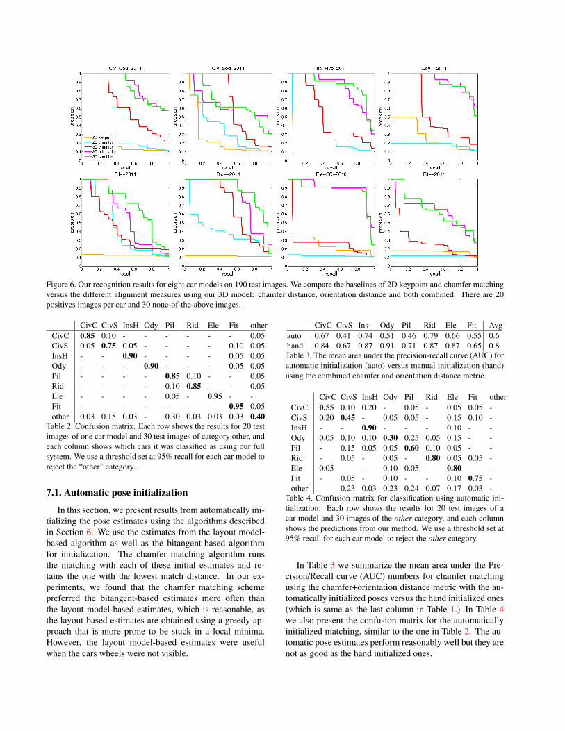
Figure 6. Our recognition results for eight car models on 190 test images. We compare the baselines of 2D keypoint and chamfer matchingversus the different alignment measures using our 3D model: chamfer distance, orientation distance and both combined. There are 20positives images per car and 30 none-of-the-above images.
CivC CivS InsH Ody Pil Rid Ele Fit otherCivC 0.85 0.10 - - - - - - 0.05CivS 0.05 0.75 0.05 - - - - 0.10 0.05InsH - - 0.90 - - - - 0.05 0.05Ody - - - 0.90 - - - 0.05 0.05Pil - - - - 0.85 0.10 - - 0.05Rid - - - - 0.10 0.85 - - 0.05Ele - - - - 0.05 - 0.95 - -Fit - - - - - - - 0.95 0.05other 0.03 0.15 0.03 - 0.30 0.03 0.03 0.03 0.40
Table 2. Confusion matrix. Each row shows the results for 20 testimages of one car model and 30 test images of category other, andeach column shows which cars it was classified as using our fullsystem. We use a threshold set at 95% recall for each car model toreject the “other” category.
7.1. Automatic pose initialization
In this section, we present results from automatically ini-tializing the pose estimates using the algorithms describedin Section 6. We use the estimates from the layout model-based algorithm as well as the bitangent-based algorithmfor initialization. The chamfer matching algorithm runsthe matching with each of these initial estimates and re-tains the one with the lowest match distance. In our ex-periments, we found that the chamfer matching schemepreferred the bitangent-based estimates more often thanthe layout model-based estimates, which is reasonable, asthe layout-based estimates are obtained using a greedy ap-proach that is more prone to be stuck in a local minima.However, the layout model-based estimates were usefulwhen the cars wheels were not visible.
CivC CivS Ins Ody Pil Rid Ele Fit Avgauto 0.67 0.41 0.74 0.51 0.46 0.79 0.66 0.55 0.6hand 0.84 0.67 0.87 0.91 0.71 0.87 0.87 0.65 0.8Table 3. The mean area under the precision-recall curve (AUC) forautomatic initialization (auto) versus manual initialization (hand)using the combined chamfer and orientation distance metric.
CivC CivS InsH Ody Pil Rid Ele Fit otherCivC 0.55 0.10 0.20 - 0.05 - 0.05 0.05 -CivS 0.20 0.45 - 0.05 0.05 - 0.15 0.10 -InsH - - 0.90 - - - 0.10 - -Ody 0.05 0.10 0.10 0.30 0.25 0.05 0.15 - -Pil - 0.15 0.05 0.05 0.60 0.10 0.05 - -Rid - 0.05 - 0.05 - 0.80 0.05 0.05 -Ele 0.05 - - 0.10 0.05 - 0.80 - -Fit - 0.05 - 0.10 - - 0.10 0.75 -other - 0.23 0.03 0.23 0.24 0.07 0.17 0.03 -
Table 4. Confusion matrix for classification using automatic ini-tialization. Each row shows the results for 20 test images of acar model and 30 images of the other category, and each columnshows the predictions from our method. We use a threshold set at95% recall for each car model to reject the other category.
In Table 3 we summarize the mean area under the Pre-cision/Recall curve (AUC) numbers for chamfer matchingusing the chamfer+orientation distance metric with the au-tomatically initialized poses versus the hand initialized ones(which is same as the last column in Table 1.) In Table 4we also present the confusion matrix for the automaticallyinitialized matching, similar to the one in Table 2. The au-tomatic pose estimates perform reasonably well but they arenot as good as the hand initialized ones.

8. ConclusionIn this paper, we have developed an approach for verify-
ing the make and model of a car from a single image takenfrom an arbitrary viewpoint using view-based 3D curvemodels. Our experiments show that these models can beaccurately aligned to test images after which chamfer dis-tance and orientation distance can be used to recognize thecar make and model under wide range of viewpoints. Wealso presented two automatic methods for recovering thefull 3D pose of the car in the test image which is used toinitialize the chamfer matching based alignment method.
In the future, we plan to incorporate appearance-basedfeatures into our view-based 3D models and extend our ap-proach to automatically learn semantic parts of cars that canbe highly discriminative for make and model recognition,such as car logos, grill, headlights and taillights. (Some pre-liminary results on incorporating taillights can be found in[10].) We will explore extensions that combine appearanceand geometric features with the goal of improving accuracyin detection, pose-estimation and make and model recogni-tion of a car from a single image.
References[1] S. Belongie, J. Malik, and J. Puzicha. Shape matching and
object recognition using shape contexts. TPAMI, 24(4):509–522, April 2002. 2
[2] M. Brown, G. Hua, and S. Winder. Discriminative learningof local image descriptors. TPAMI, 33(1):43–57, January2011. 5, 6
[3] T. Cootes, D. Cooper, C. Taylor, and J. Graham. Active shapemodels—their training and application. CVIU, 61(1):38–59,January 1995. 2
[4] L. Dlagnekov and S. Belongie. Recognizing cars. UCSD, LaJolla, CA, TR. CS2005-0833, 2005. 1, 2
[5] M. Everingham, L. Van Gool, C. K. I. Williams, J. Winn,and A. Zisserman. The PASCAL visual object classes (VOC)challenge. IJCV, 88(2):147–168, July 2010. 2
[6] R. Farrell, O. Oza, N. Zhang, V. Morariu, T. Darrell, andL. Davis. Birdlets: Subordinate categorization using volu-metric primitives and pose-normalized appearance. In ICCV,2011. 1
[7] J. Krause, M. Stark, J. Deng, L. Fei-Fei 3D Object Represen-tations for Fine-Grained Categorization . In 4th IEEE Work-shop on 3D Representation and Recognition (ICCV 2013),December 2013. 1
[8] D. Glasner, M. Galun, S. Alpert, R. Basri, andG. Shakhnarovich. Viewpoint-aware object detection andpose estimation. In ICCV, 2011. 1, 2, 3
[9] D. Hoiem and S. Savarese. Representations and Techniquesfor 3D Object Recognition and Scene Interpretation. Morgan& Claypool, 2011. 2
[10] E. Hsiao, S. Sinha, K. Ramnath, S. Baker, L. Zitnick, andR. Szeliski. Car make and model recognition using 3d curvealignment. Technical Report MSR-TR-2014-9, MicrosoftResearch, February 2014. 5, 8
[11] D. P. Huttenlocher, G. Klanderman, and W. Rucklidge.Comparing images using the Hausdorff distance. TPAMI,15(9):850–863, September 1993. 2
[12] D. P. Huttenlocher and S. Ullman. Recognizing solid objectsby alignment with an image. IJCV, 5(2):195–212, 1990. 2
[13] D. M. Jang and M. Turk. Car-rec: A real time car recognitionsystem. In WACV. IEEE Computer Society, January 2011. 2
[14] A. Laurentini. The visual hull concept for silhouette-basedimage understanding. PAMI, pages 150–162, 1994. 3
[15] M. Leotta and J. Mundy. Predicting High Resolution Im-age Edges with a Generic, Adaptive, 3-D Vehicle Model. InCVPR, 2009. 2
[16] C. Li, C. Gatenby, L. Wang, and J. Gore. A robust paramet-ric method for bias field estimation and segmentation of mrimages. In CVPR, 2009. 2
[17] Y. Li, L. Gue, and T. Kanade. Robustly aligning a shapemodel and its application to car alignment of unknown pose.TPAMI, 33(9):1860–1876, September 2011. 1, 2
[18] M.-Y. Liu, O. Tuzel, A. Veeraraghavan, and R. Chellappa.Fast directional chamfer matching. In CVPR, 2010. 2
[19] D. G. Lowe. Distinctive image features from scale-invariantkeypoints. IJCV, 60(2):91–110, November 2004. 6
[20] C. Lu et al. Contour based object detection using part bun-dles. CVIU, 114(7):827–834, July 2010. 2
[21] M. Ozuysal, V. Lepetit, and P. Fua. Pose estimation for cate-gory specific multiview object localization. In CVPR, 2009.1, 2, 3
[22] N. Payet and S. Todorovic. From contours to 3d object de-tection and pose estimation. In ICCV, November 2011. 2
[23] G. Pearce and N. Pears. Automatic make and model recogni-tion from frontal images of cars. In AVSS, September 2011.1, 2
[24] V. Petrovic and T. Cootes. Analysis of features for rigidstructure vehicle type recognition. In BMVC, 2004. 1
[25] H. Schneiderman and T. Kanade. Object detection using thestatistics of parts. IJCV, 56(3):151–177, February 2004. 2
[26] J. Shotton, A. Blake, and R. Cipolla. Contour-based learningfor object detection. In ICCV, volume 1, pages 503–510,October 2005. 2, 4
[27] S. N. Sinha, K. Ramnath, and R. Szeliski. Detecting and Re-constructing 3D Mirror Symmetric Objects. In ECCV, 2012.5
[28] H. Su, M. Sun, L. Fei-Fei, and S. Savarese. Learning a densemulti-view representation for detection, viewpoint classifi-cation and synthesis of object categories. In ICCV, 2009. 1,2
[29] R. Szeliski. Computer Vision: Algorithms and Applications.Springer, New York, 2010. 3, 5
[30] A. Thomas, V. Ferrari, B. Leibe, T. Tuytelaars, B. Schiele,and L. Van Gool. Towards multi-view object class detection.In CVPR, volume 2, pages 1589–1596, June 2006. 1, 2
[31] Y. Xiang and S. Savarese. Estimating the aspect layout ofobject categories. In CVPR, 2012. 1, 3, 4