carbon canister vapor polisher - california air resources ... · pdf filemanual no: 577013-920...
TRANSCRIPT

Manual No: 577013-920 ● Revision: B
Installation and Maintenance Guide
Carbon Canister Vapor Polisher
18-i ARB approved IOM 18 - Carbon Canister Vapor Polisher Installation and Maintenance Guide - Executive Order VR-203 and VR-204

Notice
Veeder-Root makes no warranty of any kind with regard to this publication, including, but not limited to, the implied warranties ofmerchantability and fitness for a particular purpose.
Veeder-Root shall not be liable for errors contained herein or for incidental or consequential damages in connection with thefurnishing, performance, or use of this publication.
Veeder-Root reserves the right to change system options or features, or the information contained in this publication as approvedby ARB.
This publication contains proprietary information which is protected by copyright. All rights reserved. No part of this publicationmay be modified or translated to another language without the prior written consent of Veeder-Root.
Contact TLS Systems Technical Support for additional troubleshooting information at 800-323-1799.
DAMAGE CLAIMS / LOST EQUIPMENT
Thoroughly examine all components and units as soon as they are received. If any cartons are damaged or missing, write acomplete and detailed description of the damage or shortage on the face of the freight bill. The carrier's agent must verify theinspection and sign the description. Refuse only the damaged product, not the entire shipment.
Veeder-Root must be notified of any damages and/or shortages within 30 days of receipt of the shipment, as stated in our Termsand Conditions.
VEEDER-ROOT’S PREFERRED CARRIER
1. Contact Veeder-Root Customer Service at 800-873-3313 with the specific part numbers and quantities that were missingor received damaged.
2. Fax signed Bill of Lading (BOL) to Veeder-Root Customer Service at 800-234-5350.
3. Veeder-Root will file the claim with the carrier and replace the damaged/missing product at no charge to the customer.Customer Service will work with production facility to have the replacement product shipped as soon as possible.
CUSTOMER’S PREFERRED CARRIER
1. It is the customer’s responsibility to file a claim with their carrier.
2. Customer may submit a replacement purchase order. Customer is responsible for all charges and freight associated withreplacement order. Customer Service will work with production facility to have the replacement product shipped as soon aspossible.
3. If “lost” equipment is delivered at a later date and is not needed, Veeder-Root will allow a Return to Stock without a restockingfee.
4. Veeder-Root will NOT be responsible for any compensation when a customer chooses their own carrier.
RETURN SHIPPING
For the parts return procedure, please follow the appropriate instructions in the "General Returned Goods Policy” pages in the"Policies and Literature" section of the Veeder-Root North American Environmental Products price list. Veeder-Root will notaccept any return product without a Return Goods Authorization (RGA) number clearly printed on the outside of the package.
FOR INSTALLATIONS IN THE STATE OF CALIFORNIA
Please refer to the California Air Resources Board Vapor Recovery Certification Phase II EVR Executive Order web site(www.arb.ca.gov/vapor/eo-evrphaseII.htm) for the latest manual revisions pertaining to Executive Order VR 203 (VST Phase IIEVR System) and VR 204 (VST Phase II EVR System Including ISD System).
©Veeder-Root 2008. All rights reserved.
18-ii ARB approved IOM 18 - Carbon Canister Vapor Polisher Installation and Maintenance Guide - Executive Order VR-203 and VR-204

Table of Contents
IntroductionContractor Certification Requirements ..............................................................................1Related Manuals ...............................................................................................................1Safety Precautions ............................................................................................................1Before You Begin ..............................................................................................................2Veeder-Root Parts ............................................................................................................3
Installation Procedure .................................................................................................4
MaintenanceAmbient Temperature Sensor Assembly Replacement (P/N 332796-001) ....................10Vapor Valve Filter Replacement (P/N 332901-001) ........................................................11Vapor Valve Assembly Replacement ( (P/N 332672-002) ..............................................12Canister Thermal Probe Replacement (P/N 332923-018) ..............................................14
FiguresFigure 1. Typical direct wired installation example ....................................................5Figure 2. Installing CCVP onto bracket .....................................................................6Figure 3. Canister reference dimensions and clearances .........................................7Figure 4. Locating the CCVP vapor valve connector.................................................8Figure 5. Field wiring CCVP vapor valve...................................................................8Figure 6. Epoxy sealing CCVP vapor valve field wiring connections ........................9Figure 7. Attaching CCVP vapor valve wiring to TLS-350 Console...........................9Figure 8. Remove Ambient Temperature Sensor assembly....................................10Figure 9. Replacing Ambient Temperature Sensor Assembly.................................10Figure 10. Accessing the valve filter and o-ring.........................................................11Figure 11. Replacing the valve filter and o-ring .........................................................11Figure 12. Removing Vapor Valve assembly ............................................................12Figure 13. Replacing Vapor Valve assembly and Shuttle Connector........................13Figure 14. CCVP Thermal Probe...............................................................................14
TablesTable 1. CCVP 2” Installation Kit .............................................................................3Table 2. CCVP 3” Installation Kit .............................................................................3Table 3. CCVP Piping Group Kits ...........................................................................3
18-iiiARB approved IOM 18 - Carbon Canister Vapor Polisher Installation and Maintenance Guide - Executive Order VR-203 and VR-204
Introduction
This manual contains instructions to install a Veeder-Root Carbon Canister Vapor Polisher (CCVP) into a gasoline tank vent pipe.
Contractor Certification Requirements
Veeder-Root requires the following minimum training certifications for contractors who will install and setup the equipment discussed in this manual:
Installer (Level 1) Certification: Contractors holding valid Installer Certification are approved to perform wiring and conduit routing; equipment mounting; probe, sensor and carbon canistor vapor polisher installation; tank and line preparation; and line leak detector installation.
TLS-350 Technician (Level 2/3 or 4) Certification: Contractors holding valid TLS-350 Technician Certifications are approved to perform installation checkout, startup, programming and operations training, troubleshooting and servicing for all Veeder-Root TLS-300 or TLS-350 Series Tank Monitoring Systems, including Line Leak Detection and associated accessories.
In-Station Diagnostics (ISD-PMC) Technician Certification: ISD PMC Contractors holding a valid ISD/PMC Certification are approved to perform (ISD/PMC) installation checkout, startup, programming, and operations training. This training also includes troubleshooting and service techniques for the Veeder-Root In-Station Diagnostics system. A current Veeder-Root Technician Certification is a prerequisite for the ISD/PMC course.
Veeder-Root ISD/PMC Including Carbon Canister Vapor Polisher Contractor Certification: This Certification includes Executive Orders 203, 204 and the Veeder-Root Vapor Polisher. This certification is required for setup and service of the Veeder-Root Vapor Polisher.
Warranty Registrations may only be submitted by selected Distributors.
Related Manuals
576013-879 TLS-3XX Series Consoles Site Prep Manual
577013-949 In-Station Diagnostics Install, Setup & Operation Manual
577013-948 Pressure Management Control Install, Setup and Operation Manual
576013-858 Direct Burial Cable Installation Guide
Safety Precautions
The following safety symbols may be used throughout this manual to alert you to important safety hazards and precautions.
EXPLOSIVEFuels and their vapors are extremely explo-sive if ignited.
FLAMMABLEFuels and their vapors are extremely flammable.
18-1 ARB approved IOM 18 - Carbon Canister Vapor Polisher Installation and Maintenance Guide - Executive Order VR-203 and VR-204

Introduction Before You Begin
Before You Begin
• Comply with all recommended safety practices identified by OSHA (Occupational Safety and Health Administration) and your employer.
• Follow all installation requirements as per NFPA (National Fire Protection Association) 30, 30A, and 70.
ELECTRICITYHigh voltage exists in, and is supplied to, the device. A potential shock hazard exists.
TURN POWER OFFLive power to a device creates a potential shock hazard. Turn Off power to the device and associ-ated accessories when servicing the unit.
READ ALL RELATED MANUALSKnowledge of all related procedures before you begin work is important. Read and understand all manuals thoroughly. If you do not understand a procedure, ask someone who does.
USE SAFETY BARRICADESUnauthorized people or vehicles in the work area are dangerous. Always use safety cones or barri-cades, safety tape, and your vehicle to block the work area.
WARNINGHeed the adjacent instructions to avoid dam-age to equipment, property, environment or personal injury.
WEAR EYE PROTECTIONWear eye protection when working with pressur-ized fuel lines or epoxy sealant to avoid possible eye injury.
INJURYCareless or improper handling of materials can result in bodily injury.
GLOVESWear gloves to protect hands from irritation or injury.
WARNINGThis product is to be installed and operated in the highly combustible environment of a gasoline station where flammable liquids and explosive vapors may be present.ATTEMPTING TO SERVICE TANK MONITORS AND EQUIPMENT WITHOUT PROPER TRAINING CAN CAUSE DAMAGE TO PROPERTY, ENVIRONMENT, RESULTING IN PERSONAL INJURY OR DEATH.The following hazards exist:
1. Electrical shock resulting in serious injury or death may result if power is on during installation and the device is improperly installed.
2. Product leakage could cause severe environmental damage or explosion resulting in death, serious personal injury, property loss and equipment damage.
Observe the following precautions:1. Read and follow all instructions in this manual, including all safety warnings.2. Comply with all applicable codes including: the National Electrical Code; federal,
state, and local codes; and other applicable safety codes. 3. Before installing this device, turn Off, tag/lock out power to the system, including
console and submersible pumps. 4. To protect yourself and others from being struck by vehicles, block off your work
area during installation or service.5. Substitution of components may impair intrinsic safety.
OFF
OFF
18-2 ARB approved IOM 18 - Carbon Canister Vapor Polisher Installation and Maintenance Guide - Executive Order VR-203 and VR-204
Introduction Veeder-Root Parts
• Where separate instrinsically safe circuits are installed in the same raceway they must be segregated in accordance with Article 504 of the NEC.
• Review and comply with all the safety warnings in the installation manuals and any other national, State or Local requirements.
• If the Carbon Canister is being wired directly to a TLS console, a 2-conductor, 18 AWG shielded cable must be installed in intrinsically safe conduit from the intrinsically safe wiring compartment of the TLS console to the carbon canister. If direct burial cable is used, it must comply with all requirements of the local authority having jurisdiction. Reference manual 576013-879 which describes special requirements regarding direct burial installations. Also, see manual 576013-858 for a complete listing of required materials and an overview of direct burial installations.
• Use only UL certified Gas/TFE yellow teflon tape on all fittings. Do not use pipe dope to seal pipe threads or fittings in and out of the CCVP.
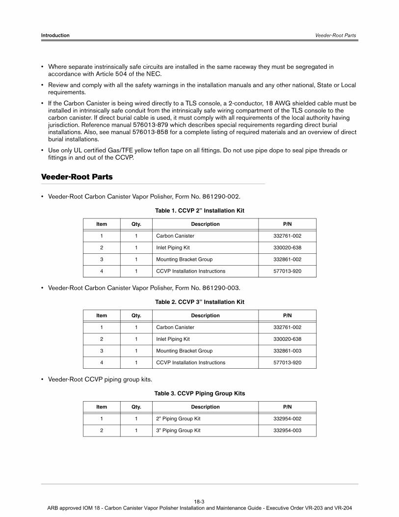
Veeder-Root Parts
• Veeder-Root Carbon Canister Vapor Polisher, Form No. 861290-002.
• Veeder-Root Carbon Canister Vapor Polisher, Form No. 861290-003.
• Veeder-Root CCVP piping group kits.
Table 1. CCVP 2” Installation Kit
Item Qty. Description P/N
1 1 Carbon Canister 332761-002
2 1 Inlet Piping Kit 330020-638
3 1 Mounting Bracket Group 332861-002
4 1 CCVP Installation Instructions 577013-920
Table 2. CCVP 3” Installation Kit
Item Qty. Description P/N
1 1 Carbon Canister 332761-002
2 1 Inlet Piping Kit 330020-638
3 1 Mounting Bracket Group 332861-003
4 1 CCVP Installation Instructions 577013-920
Table 3. CCVP Piping Group Kits
Item Qty. Description P/N
1 1 2” Piping Group Kit 332954-002
2 1 3” Piping Group Kit 332954-003
18-3 ARB approved IOM 18 - Carbon Canister Vapor Polisher Installation and Maintenance Guide - Executive Order VR-203 and VR-204
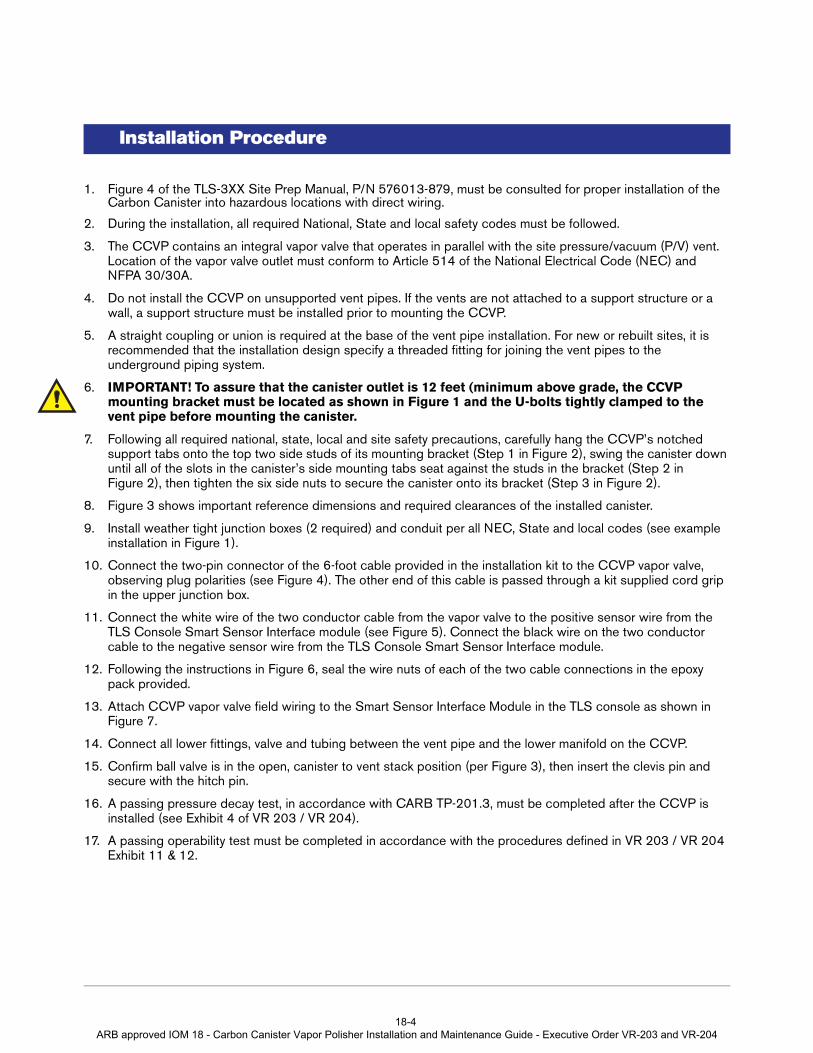
Installation Procedure
1. Figure 4 of the TLS-3XX Site Prep Manual, P/N 576013-879, must be consulted for proper installation of the Carbon Canister into hazardous locations with direct wiring.
2. During the installation, all required National, State and local safety codes must be followed.
3. The CCVP contains an integral vapor valve that operates in parallel with the site pressure/vacuum (P/V) vent. Location of the vapor valve outlet must conform to Article 514 of the National Electrical Code (NEC) and NFPA 30/30A.
4. Do not install the CCVP on unsupported vent pipes. If the vents are not attached to a support structure or a wall, a support structure must be installed prior to mounting the CCVP.
5. A straight coupling or union is required at the base of the vent pipe installation. For new or rebuilt sites, it is recommended that the installation design specify a threaded fitting for joining the vent pipes to the underground piping system.
6. IMPORTANT! To assure that the canister outlet is 12 feet (minimum above grade, the CCVP mounting bracket must be located as shown in Figure 1 and the U-bolts tightly clamped to the vent pipe before mounting the canister.
7. Following all required national, state, local and site safety precautions, carefully hang the CCVP’s notched support tabs onto the top two side studs of its mounting bracket (Step 1 in Figure 2), swing the canister down until all of the slots in the canister’s side mounting tabs seat against the studs in the bracket (Step 2 in Figure 2), then tighten the six side nuts to secure the canister onto its bracket (Step 3 in Figure 2).
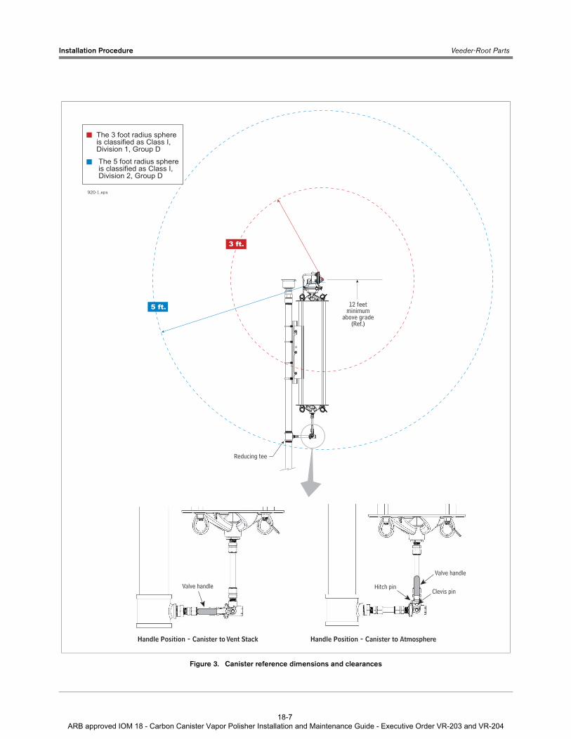
8. Figure 3 shows important reference dimensions and required clearances of the installed canister.
9. Install weather tight junction boxes (2 required) and conduit per all NEC, State and local codes (see example installation in Figure 1).
10. Connect the two-pin connector of the 6-foot cable provided in the installation kit to the CCVP vapor valve, observing plug polarities (see Figure 4). The other end of this cable is passed through a kit supplied cord grip in the upper junction box.
11. Connect the white wire of the two conductor cable from the vapor valve to the positive sensor wire from the TLS Console Smart Sensor Interface module (see Figure 5). Connect the black wire on the two conductor cable to the negative sensor wire from the TLS Console Smart Sensor Interface module.
12. Following the instructions in Figure 6, seal the wire nuts of each of the two cable connections in the epoxy pack provided.
13. Attach CCVP vapor valve field wiring to the Smart Sensor Interface Module in the TLS console as shown in Figure 7.
14. Connect all lower fittings, valve and tubing between the vent pipe and the lower manifold on the CCVP.
15. Confirm ball valve is in the open, canister to vent stack position (per Figure 3), then insert the clevis pin and secure with the hitch pin.
16. A passing pressure decay test, in accordance with CARB TP-201.3, must be completed after the CCVP is installed (see Exhibit 4 of VR 203 / VR 204).
17. A passing operability test must be completed in accordance with the procedures defined in VR 203 / VR 204 Exhibit 11 & 12.
18-4 ARB approved IOM 18 - Carbon Canister Vapor Polisher Installation and Maintenance Guide - Executive Order VR-203 and VR-204
Installation Procedure Veeder-Root Parts
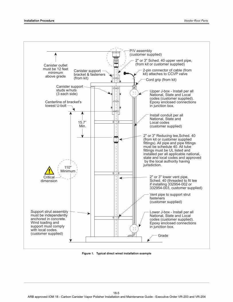
Figure 1. Typical direct wired installation example
Canister outletmust be 12 feet
minimumabove grade
2-pin connector of cable (from kit) attaches to CCVP valve
Cord grip (from kit)
Canister supportbracket & fasteners(from kit)
P/V assembly(customer supplied)
2" or 3" Sched. 40 upper vent pipe,(from kit or customer supplied)
Grade
Lower J-box - Install per allNational, State and Localcodes (customer supplied).Epoxy enclosed connections in junction box.
Upper J-box - Install per allNational, State and Localcodes (customer supplied).Epoxy enclosed connections in junction box.
Install conduit per allNational, State and Local codes (customer supplied)
15.7” Min.
2" or 3" Reducing tee,Sched. 40 (from kit or customer suppliedfittings). All pipe and pipe fittings must be schedule 40. All tubefittings must be UL listed and installed per all applicable national, state and local codes and approved by the local authority having jurisdiction.
Vent pipe to support strutfasteners(customer supplied)
Support strut assembly must be independently anchored in concrete. Wind loading and support must comply with local codes.(customer supplied)
2" or 3" lower vent pipe,Sched. 40 (threaded to fit teeif installing 332954-002 or332954-003, customer supplied)
Criticaldimension
Canister supportstuds w/nuts(3 each side)
Centerline of bracket'slowest U-bolt
110"Minimum
18-5 ARB approved IOM 18 - Carbon Canister Vapor Polisher Installation and Maintenance Guide - Executive Order VR-203 and VR-204

Installation Procedure Veeder-Root Parts
Figure 2. Installing CCVP onto bracket
1
2
3
isd-evr\ccvp7.eps
18-6 ARB approved IOM 18 - Carbon Canister Vapor Polisher Installation and Maintenance Guide - Executive Order VR-203 and VR-204
Installation Procedure Veeder-Root Parts
Figure 3. Canister reference dimensions and clearances
12 feetminimum
above grade(Ref.)
Reducing tee
The 5 foot radius sphereis classified as Class I, Division 2, Group D
The 3 foot radius sphereis classified as Class I, Division 1, Group D
3 ft.
920-1.eps
Clevis pin
Valve handle
Hitch pinValve handle
Handle Position - Canister to AtmosphereHandle Position - Canister to Vent Stack
5 ft.
18-7 ARB approved IOM 18 - Carbon Canister Vapor Polisher Installation and Maintenance Guide - Executive Order VR-203 and VR-204

Installation Procedure Veeder-Root Parts
Figure 4. Locating the CCVP vapor valve connector
Figure 5. Field wiring CCVP vapor valve
Attach 2-pin connectorto CCVP valve connector (other end of cable connects to TLS field wiring in upper j-box)
Carbon Canister
Cable to CCVPthermal probe (factoryinstalled)
isd-evr\polisher\ccvp16.eps
Black
White
ToSmart Sensor
Interface Module2-conductor cableto CC vapor valve
1/2'' rigidconduit
Seal-off(only req'd
at lowerj-box)
Epoxy sealed connections in aweatherproof junction boxisd-evr\ccvp5.eps
18-8 ARB approved IOM 18 - Carbon Canister Vapor Polisher Installation and Maintenance Guide - Executive Order VR-203 and VR-204

Installation Procedure Veeder-Root Parts
Figure 6. Epoxy sealing CCVP vapor valve field wiring connections
Figure 7. Attaching CCVP vapor valve wiring to TLS-350 Console
isd-evr\ccvp8.eps
Tie wrap
Wire nuts
A CBMake sure that the ends of cable sheathing are sub-merged in sealant
Instructions:NOTE: When temperature is below 50°F (10°C), keep
resin in a warm place prior to mixing (e.g., in an inside pocket next to body).
1. Open epoxy sealant package, and remove resin pak.2. Holding resin pak as shown in A, bend pak along
long length.3. As shown in B, firmly squeeze the RED SIDE of the
resin, forcing it through the center seal and into BLACK SIDE.
4. Mix thoroughly to a uniform color by squeezing contents back and forth 25-30 times.
5. Squeeze mixed, warm resin into one end of bag and cutoff other end.
6. Slowly insert wiring connections into sealing pack until they fit snugly against the opposite end as shown in C.
7. Twist open end of bag and use tie wrap to close it off and position the tie wrapped end up until the resin jells.
CAUTION: Epoxy sealant is irritating to eyes, respiratory system, and skin. Can cause allergic skin reaction. Contains: epoxy resin and Cycloaliphatic epoxycarboxylate.
Precautions: Wear suitable protective clothing, gloves, eye, and face protection. Use only in well ventilated areas. Wash thoroughly before eating, drinking, or smoking.
isd-evr\ccvp4.eps
Attach Cable Shields to Ground Lug Closest to Conduit Entry
SMARTSENSOR
MAXIMUMOUTPUT RATINGS
13 VDC0.2 AMP
+ + + + + + +1 2 3 4 5 6 7
SMART SENSOR / PRESS MODULE
Rigid Conduit (enters Consolethrough an I.S. Bay knockout)
INTRINSICALLY SAFE BAY OF TLS CONSOLE
+CCVP Valve
18-9 ARB approved IOM 18 - Carbon Canister Vapor Polisher Installation and Maintenance Guide - Executive Order VR-203 and VR-204

Maintenance
Ambient Temperature Sensor Assembly Replacement (P/N 332796-001)
1. Remove the three #25 Torx screws holding the Ambient Temperature Sensor assembly to the Vapor Valve assembly (see Figure 8).
2. Pull the sensor assembly straight out (unplugging it).
3. Align the replacement Ambient Temperature Sensor assembly’s connector with the connector in the Vapor Valve assembly and push in the assembly until it seats against the Vapor Valve assembly (see Figure 9).
4. Replace the three #25 Torx screws in the Ambient Temperature Sensor assembly cover until tight.
Figure 8. Remove Ambient Temperature Sensor assembly
Figure 9. Replacing Ambient Temperature Sensor Assembly
#25 Torx screw (3)
Ambient TemperatureSensor assy.
Vapor Valve assembly
920\ccvp18.eps
Ambient TemperatureSensor Assembly with Gasket (P/N 332796-001)
Align connectors and push in
Vapor Valve assembly
920\ccvp19.eps
18-10 ARB approved IOM 18 - Carbon Canister Vapor Polisher Installation and Maintenance Guide - Executive Order VR-203 and VR-204

Maintenance Vapor Valve Filter Replacement (P/N 332901-001)
Vapor Valve Filter Replacement (P/N 332901-001)
1. Remove the four 1/4 -20 x 1” hex key bolts from the top of the Vapor Valve Filter housing (see Figure 10).
2. Swing the housing top back and remove the filter plate from its seat and the o-ring from its groove in the Vapor Valve Filter housing’s lower half (see Figure 11).
3. Install a new o-ring (P/N 512700-275) in the groove and insert a new filter plate (P/N 332901-001) into its seat in the lower half of the housing, close the cover and screw in the four 1/4-20 hex key bolts until tight.
4. Run the CCVP Leakage and Flow test.
Figure 10. Accessing the valve filter and o-ring
Figure 11. Replacing the valve filter and o-ring
1/4-20 hex key bolts (4)
Valve filter housing hinged top
isd-evr\polisher\ccvp20.eps
Porous filter plate(P/N 332901-001)
O-ring (P/N 512700-275)
isd-evr\polisher\ccvp21.eps
18-11 ARB approved IOM 18 - Carbon Canister Vapor Polisher Installation and Maintenance Guide - Executive Order VR-203 and VR-204

Maintenance Vapor Valve Assembly Replacement ( (P/N 332672-002)
Vapor Valve Assembly Replacement ( (P/N 332672-002)
Figure 12. Removing Vapor Valve assembly
1. Remove the cables from the two connectors on the Vapor Valve assembly.
2. Remove the two #25 Torx head screws that secures the Vapor Valve assembly to the Vapor Valve Filter housing (see Figure 12).
3. Remove the Vapor Valve assembly (and remove the Shuttle Connector if necessary, see Figure 13).
4. Push the replacement Shuttle connector into the port on the back of the replacement Vapor Valve assembly. Remove and retain the two #25 Torx Taptite screws on each side of the Shuttle connector port on the back of the back Vapor Valve assembly.
5. Line up the Vapor Valve assembly shuttle connector with the port in the Vapor Valve Filter housing and push the Vapor Valve assembly in until it seats against the Vapor Valve Filter housing.
6. Insert the two #25 Torx head taptite screws through the holes in each side of the Vapor Valve Filter housing and screw them into the Vapor Valve assembly until tight (see Figure 13).
7. Reconnect the two cables to the two connectors on the Vapor Valve assembly.
8. Run CCVP Leakage and Flow test.
isd-evr\polisher\ccvp22.eps
Carbon Canister
Vapor Valve assembly
Vapor Valve Filter housing
#25 Torx screws (2)
18-12 ARB approved IOM 18 - Carbon Canister Vapor Polisher Installation and Maintenance Guide - Executive Order VR-203 and VR-204

Maintenance Vapor Valve Assembly Replacement ( (P/N 332672-002)
Figure 13. Replacing Vapor Valve assembly and Shuttle Connector
Vapor Valveassembly
#25 Torx hd taptite
screws (2)
Shuttleconnector
ports
Shuttle connector(inserts into 2 ports)
isd-evr\ccvp27.eps
18-13 ARB approved IOM 18 - Carbon Canister Vapor Polisher Installation and Maintenance Guide - Executive Order VR-203 and VR-204

Maintenance Canister Thermal Probe Replacement (P/N 332923-018)
Canister Thermal Probe Replacement (P/N 332923-018)
Figure 14. CCVP Thermal Probe
1. Remove the thermal probe cable connector from the back of the Vapor Valve assembly (see Figure 14).
2. Using a 9/16”open-end wrench, remove the thermal probe from the top of the CCVP.
3. Install and tighten the replacement Thermal Probe into its port in the CCVP and reconnect the cable to the Vapor Valve connector.
4. Run CCVP Leakage and Flow test.
ThermalProbe
Thermal Probeconnection
to Vapor Valve
isd-evr\polisher\ccvp24.eps
18-14 ARB approved IOM 18 - Carbon Canister Vapor Polisher Installation and Maintenance Guide - Executive Order VR-203 and VR-204

For technical support, sales orother assistance, please visit:
www.veeder.com
18-15 ARB approved IOM 18 - Carbon Canister Vapor Polisher Installation and Maintenance Guide - Executive Order VR-203 and VR-204