carbon dioxide co - keison products · carbon dioxide co 2 ... carbon dioxide is a standard...
TRANSCRIPT

C A R B O N D I O X I D E C O 2I n d u s t r i a l f i r e s u p p r e s s i o n s y s t e m s
Kidde engineers developed carbon dioxide fire extinguishing over 80 years
ago and Kidde have been responsible for every major improvement that has
been made in this branch of fire protection. Kidde Fire Protection benefits
from the accumulated experience of thousands of installations in power
plants, industrial plants, oil refineries, electronic processes, on ships and in a
wide variety of hazardous areas.
CO2 is versatile
The CO2 is stored as liquid, under
pressure. When a system is activated,
the liquid CO2 flows through discharge
pipework to specially designed
nozzles. The agent’s low boiling point
means that the liquid vaporises rapidly
during the discharge, providing a
penetrative three-dimensional action.
The rapid expansion of the gaseous
agent allows fires to be targeted even
in the most inaccessible areas of the
risk.
Fire is extinguished by reducing the
oxygen level in the risk area to the
point where combustion cannot be
sustained. Cooling is a secondary
action of the agent; this feature is
used in local applications where the
liquid phase of the discharge is
applied directly to the fire and risk
materials.
CO2 is fast and efficient
The Kidde Fire Protection High
Pressure CO2 system uses large bore
cylinder valves, enabling high mass
flow rates to be achieved. The fast
action of the control system and valve
enables the system to react within the
first few seconds of a fire that can
make the difference between a
nuisance and a disaster.
CO2 is clean
CO2 is a colourless, odourless, dry, inert
gas and is one of the most familiar of
all gases. After extinguishing a fire it
vapourises fully leaving no residue.
There is no mess, nothing to clear up,
no water damage. It is non-corrosive
and will not contaminate foodstuffs. It
is non-conductive and so can be used
on energised electrical equipment. It
can be safely used to protect delicate
electronic equipment, antiquities or
archive materials.
CO2 is low cost
Carbon dioxide is a standard
commercial product with many other
uses and it is readily available
throughout the world. Because of its
universal use it can be obtained
inexpensively and this is an important
consideration when frequent
recharging of storage containers is
necessary as in local application
systems, where fires may be more
frequent.

C A R B O N D I O X I D E C O 2
Benefits
• High flow ‘Klem’ cylinder valve
• Manual or Automatic operation
• Pilot cylinder or Direct Acting
Solenoid operating system
• Continuous weight monitoring
option
• Design compliance with BS5306-4
• Fully compatible with Kidde Fire
Protection control panels
Typical applications
• Flammable liquid storage areas
• Printing presses, flow solder
machines
• Quench tanks/exhaust fume ducts
• Paint spray booths
• Fryers/ovens
• EDP/computer rooms and floor
voids*
• Commercial kitchens
• Transformers
• Generators
* CO2 is not the agent of choice for
manned areas. Please contact Kidde Fire
Protection Applications Department for
more information.
System design
Details of both total flooding and
local application systems are contained
in the Kidde Fire Protection CO2
Design Manual.
Flexible design
The wide range of components
manufactured by Kidde Fire Protection
enables systems to be engineered to
suit individual customer requirements.
Systems can be either automatically or
manually operated and arranged to
protect single or multi-zone hazards
and with any number of reserve
discharges. Automatic control can be
achieved mechanically, pneumatically
or electrically or by any combination
of these to suit site conditions.
Facilities are available for providing a
pre-alarm and delayed discharge as
well as various methods of preventing
automatic release while protected
rooms are occupied by personnel.
Audible and visual indications of
system control can be provided
together with facilities to
automatically shut fuel valves, fire
doors, dampers and shutters by either
mechanical or electrical devices.
CO2 is stored in solid drawn steel
cylinders manufactured to European
Standards. The storage pressure varies
with ambient temperature and is 58.6
bar at 21°C.
Any number of cylinders can be
manifolded together and
simultaneously released to provide the
total design requirement of CO2.
Approvals
Major approvals for the Kidde Fire
Protection CO2 system include:
• FM Global
• Lloyd’s Register
• American Bureau of Shipping
• Det Norske Veritas
• UK Maritime and Coastguard
Agency (MCA)
• Germanischer Lloyd
Control headwith pilotcylinder
Dischargenozzles
Manual pullbox
PressureSwitch
Pressure Trip Cylinder contents monitoring option
Solenoid forcontrol head
Klem valvewith metronactuator
Klem valvewith solenoidactuation
2

C A R B O N D I O X I D E C O 2
Total Flooding Systems
Total flooding systems extinguish fires
by rapidly discharging CO2 into an
enclosed volume to create an
atmosphere that is incapable of
supporting combustion.
The agent mixes homogeneously in
the risk area to generate a CO2
concentration by volume of at least
34%. This concentration of CO2
presents a serious hazard to personnel
and under no circumstances should
CO2 be released into areas that may be
manned at the time of discharge.
Automatic CO2 Extinguishing System
Total flood CO2 systems are ideal for
unmanned applications such as
transformer rooms, remote switch
rooms, generators and archives. All
systems should be installed with safety
systems in place to prevent the
inadvertent release of agent into
occupied spaces. Kidde Fire Protection
offers time delays, isolating valves
including distribution valves and
control head lockout pins to facilitate
the safe use of CO2.
19
17
13
17
20
10
121114
Electrical Transmission Path
CO2 Pipework
Pilot Circuit
15
10 78 9 1 4
1618 2 6 3 5
Legend1 CO2 cylinder2 Cylinder valve and actuator3 Solenoid4 Nitrogen pilot cylinder and control head5 Manual push button6 Pressure relief device7 Isolating valve8 Discharge pressure switch9 Pilot bleed10 Pressure trip11 Extinguishing Control Panel12 Status indicator unit13 Status indicator with release control14 1st stage alarm sounder15 2nd stage alarm sounder16 Discharge nozzle17 Fire door18 Smoke detector19 Air exhaust duct20 Self-closing weight operated damper
3
Key
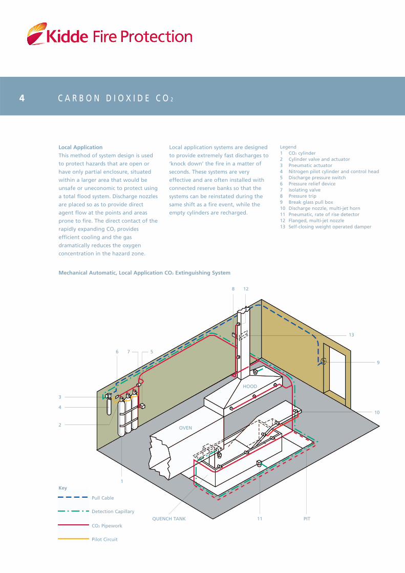
Local Application
This method of system design is used
to protect hazards that are open or
have only partial enclosure, situated
within a larger area that would be
unsafe or uneconomic to protect using
a total flood system. Discharge nozzles
are placed so as to provide direct
agent flow at the points and areas
prone to fire. The direct contact of the
rapidly expanding CO2 provides
efficient cooling and the gas
dramatically reduces the oxygen
concentration in the hazard zone.
Mechanical Automatic, Local Application CO2 Extinguishing System
Local application systems are designed
to provide extremely fast discharges to
‘knock down’ the fire in a matter of
seconds. These systems are very
effective and are often installed with
connected reserve banks so that the
systems can be reinstated during the
same shift as a fire event, while the
empty cylinders are recharged.
Legend1 CO2 cylinder2 Cylinder valve and actuator3 Pneumatic actuator4 Nitrogen pilot cylinder and control head5 Discharge pressure switch6 Pressure relief device7 Isolating valve8 Pressure trip9 Break glass pull box10 Discharge nozzle, multi-jet horn11 Pneumatic, rate of rise detector12 Flanged, multi-jet nozzle13 Self-closing weight operated damper
C A R B O N D I O X I D E C O 2
9
13
HOOD
OVEN
128
11
1
10
PITQUENCH TANK
76 5
4
3
2
4
Pull Cable
Detection Capillary
CO2 Pipework
Pilot Circuit
Key
C A R B O N D I O X I D E C O 2
testing. If the test shows that the
leakage would reduce the hold time
below that specified for the fire type,
additional CO2 must be provided.
The release of CO2 into a tightly sealed
enclosure could result in damage
caused by pressure variations during
discharge. Normally the natural
leakage of an enclosure is adequate to
prevent damage but in some cases
pressure relief venting may be
required.
System Information
Local Application Systems
Volume Method
The volume method of system design
is used where the fire hazard consists
of three dimensional irregular objects
that cannot easily be reduced to
equivalent surface area.
The total discharge rate of the system
is based on the volume of an assumed
enclosure surrounding the hazard. The
basic design rate is 16 kg/min/m3 but
this can be reduced according to the
degree of existing enclosure on site.
Area Method
The quantity of CO2 required is based
upon the total discharge rate from a
carefully sited nozzle arrangement, a
sufficient number of nozzles being
used to adequately cover the entire
area on the basis of the unit area
protected by each nozzle.
For this method of design, where a
horizontal or vertical flat surface is
protected, nozzles are to be
positioned in accordance with the
guidance of the Kidde Fire Protection
CO2 Design Manual. The position and
distance from the hazard has a critical
effect on the quantity of CO2 required.
This protection methodology is well
suited to painting, dipping and drying
type applications.
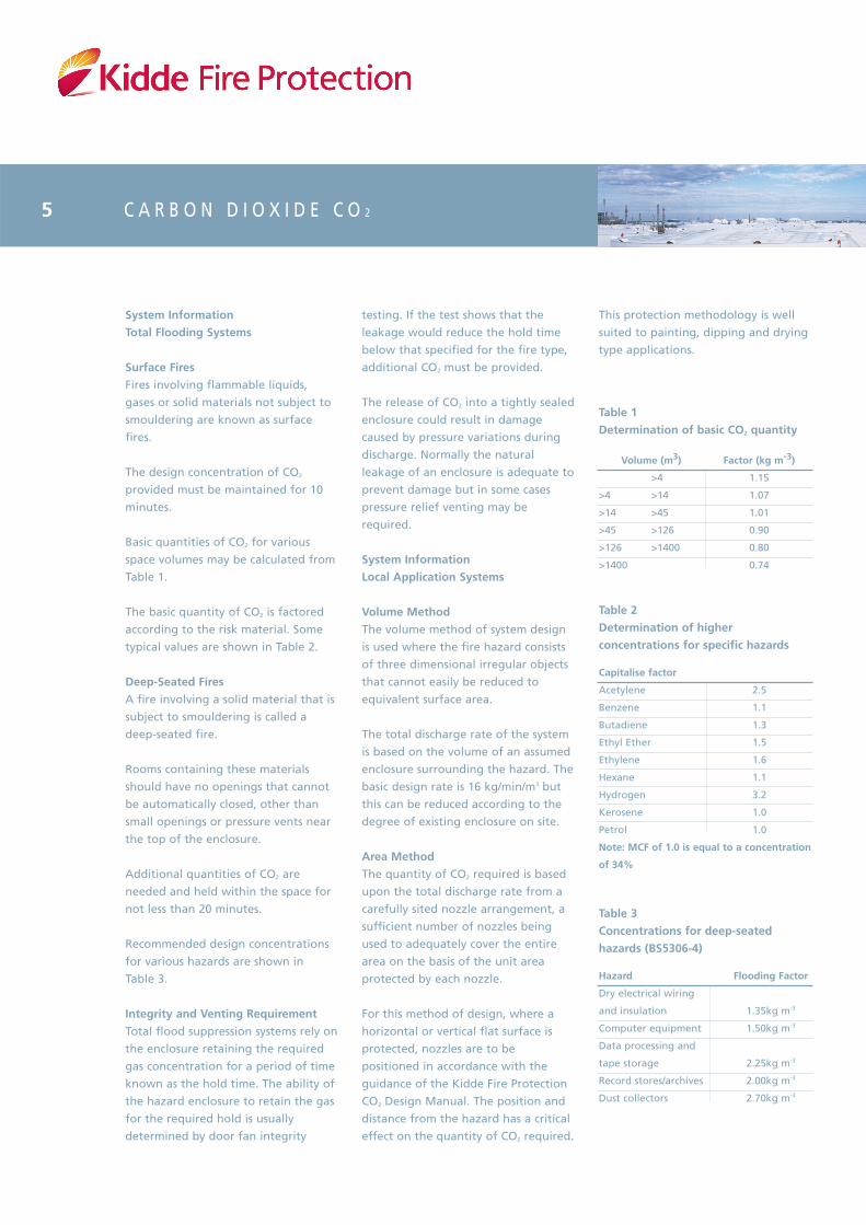
Table 3
Concentrations for deep-seated
hazards (BS5306-4)
Hazard
Dry electrical wiring
and insulation
Computer equipment
Data processing and
tape storage
Record stores/archives
Dust collectors
Flooding Factor
1.35kg m-3
1.50kg m-3
2.25kg m-3
2.00kg m-3
2.70kg m-3
Table 1
Determination of basic CO2 quantity
Volume (m3)
>4
>4 >14
>14 >45
>45 >126
>126 >1400
>1400
Factor (kg m-3)
1.15
1.07
1.01
0.90
0.80
0.74
Table 2
Determination of higher
concentrations for specific hazards
Capitalise factor
Acetylene
Benzene
Butadiene
Ethyl Ether
Ethylene
Hexane
Hydrogen
Kerosene
Petrol
Note: MCF of 1.0 is equal to a concentration
of 34%
2.5
1.1
1.3
1.5
1.6
1.1
3.2
1.0
1.0
System Information
Total Flooding Systems
Surface Fires
Fires involving flammable liquids,
gases or solid materials not subject to
smouldering are known as surface
fires.
The design concentration of CO2
provided must be maintained for 10
minutes.
Basic quantities of CO2 for various
space volumes may be calculated from
Table 1.
The basic quantity of CO2 is factored
according to the risk material. Some
typical values are shown in Table 2.
Deep-Seated Fires
A fire involving a solid material that is
subject to smouldering is called a
deep-seated fire.
Rooms containing these materials
should have no openings that cannot
be automatically closed, other than
small openings or pressure vents near
the top of the enclosure.
Additional quantities of CO2 are
needed and held within the space for
not less than 20 minutes.
Recommended design concentrations
for various hazards are shown in
Table 3.
Integrity and Venting Requirement
Total flood suppression systems rely on
the enclosure retaining the required
gas concentration for a period of time
known as the hold time. The ability of
the hazard enclosure to retain the gas
for the required hold is usually
determined by door fan integrity
5
10
Cyl
10
•
•
10
10
4
4
4
4
12
1
1
1
1
1
1
9
9
Cyl
9
•
•
9
9
6
6
12
1
1
1
1
1
1
8
8
Cyl
8
•
•
8
8
2
4
2
4
10
1
1
1
1
1
1
7
7
Cyl
7
•
•
7
7
4
2
4
2
8
1
1
1
1
1
1
6
6
Cyl
6
•
•
6
6
4
2
8
1
1
1
1
1
1
5
5
Cyl
5
1
3
5
5
2
2
2
2
6
1
1
1
1
1
1
4
4
Cyl
4
1
2
4
4
4
2
4
1
1
1
1
1
1
3
3
Cyl
3
1
2
3
3
2
2
4
1
1
1
1
1
1
2
2
Cyl
2
1
2
2
2
2
2
2
1
1
1
1
1
1
1
Part No.
K24069/FM
or E7194-001-01
K21207
K21209
K21211
K21213
K24267D
K97112
K62341
K17238
K17235
K13744
K13745
K62752
K62755
K62303
K62422B
K62462
K62487
K24051
K93434
K93433
K62943
1
Cyl
1
1
1
1
1
1
1
1
1
1
2
C A R B O N D I O X I D E C O 2
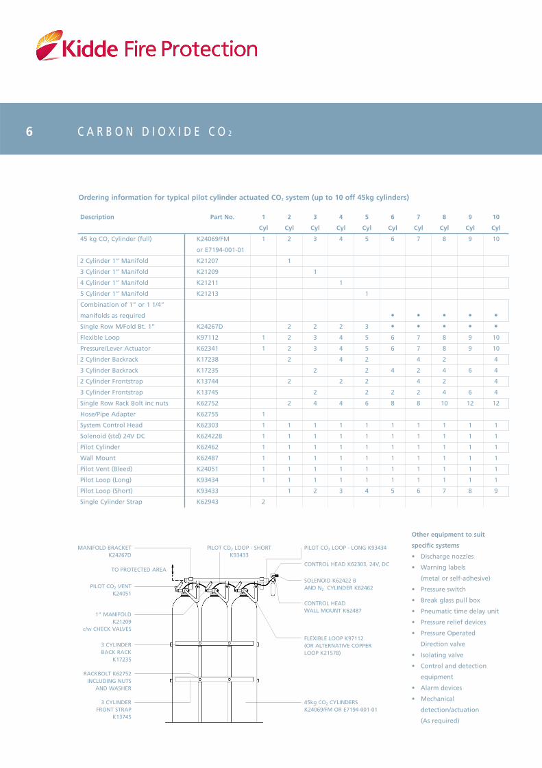
Ordering information for typical pilot cylinder actuated CO2 system (up to 10 off 45kg cylinders)
Description
45 kg CO2 Cylinder (full)
2 Cylinder 1” Manifold
3 Cylinder 1” Manifold
4 Cylinder 1” Manifold
5 Cylinder 1” Manifold
Combination of 1” or 1 1/4”
manifolds as required
Single Row M/Fold Bt. 1”
Flexible Loop
Pressure/Lever Actuator
2 Cylinder Backrack
3 Cylinder Backrack
2 Cylinder Frontstrap
3 Cylinder Frontstrap
Single Row Rack Bolt inc nuts
Hose/Pipe Adapter
System Control Head
Solenoid (std) 24V DC
Pilot Cylinder
Wall Mount
Pilot Vent (Bleed)
Pilot Loop (Long)
Pilot Loop (Short)
Single Cylinder Strap
MANIFOLD BRACKETK24267D
PILOT CO2 LOOP - SHORTK93433
PILOT CO2 LOOP - LONG K93434
PILOT CO2 VENTK24051
1” MANIFOLDK21209
c/w CHECK VALVES
3 CYLINDERBACK RACK
K17235
RACKBOLT K62752INCLUDING NUTS
AND WASHER
3 CYLINDERFRONT STRAP
K13745
45kg CO2 CYLINDERSK24069/FM OR E7194-001-01
FLEXIBLE LOOP K97112(OR ALTERNATIVE COPPERLOOP K21578)
CONTROL HEADWALL MOUNT K62487
SOLENOID K62422 BAND N2 CYLINDER K62462
CONTROL HEAD K62303, 24V, DCTO PROTECTED AREA
Other equipment to suit
specific systems
• Discharge nozzles
• Warning labels
(metal or self-adhesive)
• Pressure switch
• Break glass pull box
• Pneumatic time delay unit
• Pressure relief devices
• Pressure Operated
Direction valve
• Isolating valve
• Control and detection
equipment
• Alarm devices
• Mechanical
detection/actuation
(As required)
6

E L E C T R I C A L L Y A C T U A T E D C O 2 S Y S T E M
Direct-acting CO2 solenoid
Designed for use with standard
Kidde Fire Protection 45kg CO2
cylinders, the direct-acting solenoid
allows CO2 systems to be actuated
electrically without the need for a
separate pilot nitrogen supply.
The solenoid actuation system uses a
modified version of the existing
cylinder valve, replacing the nitrogen
pilot cylinder with a solenoid directly
coupled to the CO2 cylinder valve. The
system also retains the facility for local
manual release or via a mechanical
pull cable.
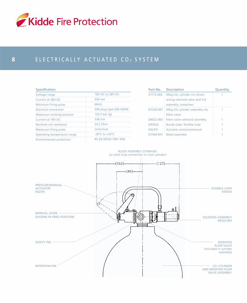
Operation
The pressure/manual actuator
(K62341) is fitted to the cylinder
(Klem) valve, with the solenoid
assembly (D8522-003) attached to the
poppet orifice connection by means of
a swivel nut and O-ring seal. The
solenoid assembly has a flexible hose
connection to the pressure/manual
actuator.
In the unactivated state, the
pneumatic actuator is subject only to
atmospheric pressure and the Klem
valve remains closed. On receipt of an
electrical signal from an extinguishant
release control panel, the solenoid coil
is activated, releasing high pressure
CO2 from the cylinder. The CO2 passes
through a short flexible hose to the
pressure/manual actuator, which then
operates the Klem valve, allowing CO2
to exit via the discharge port. Further
CO2 cylinders may be discharged by
interconnecting the pressure/manual
actuators using flexible pilot hoses
(K93433).
Metron actuator with manual lever
(D8521-002), ideal for single cylinder
electrical operation, is also available.
7
E L E C T R I C A L L Y A C T U A T E D C O 2 S Y S T E M
Kidde Fire ProtectionThame Park Road, Thame, Oxfordshire OX9 3RTTel: +44 (0)1844 265003. Fax: +44 (0)1844 265156. E-mail: [email protected] Web: www.kfp.co.uk
PRESSURE/MANUALACTUATORK62341
MANUAL LEVER(SHOWN IN FIRED POSITION) SOLENOID ASSEMBLY
D8522-003
SAFETY PIN
RETENTION PIN
MODIFIEDKLEM VALVE
(included in cylinderassembly)
CO2 CYLINDERAND MODIFIED KLEM
VALVE ASSEMBLY
BLEED ASSEMBLY D7564-001(or pilot loop connection to next cylinder)
FLEXIBLE LOOPK93433
© Kidde Fire Protection6230/2 03/06
Specification
Voltage range
Current at 28V DC
Minimum firing pulse
Electrical connection
Maximum working pressure
Current at 18V DC
Nominal coil resistance
Maximum firing pulse
Operating temperature range
Environmental protection
18V DC to 28V DC
526 mA
60mS
DIN plug type DIN 43650
152.5 bar (g)
338 mA
53.2 Ohm
Unlimited
-20°C to +55°C
BS EN 60529 1991 IP65
Part No.
E7772-004
D7226-007
D8522-003
K93433
K62341
D7564-001
Description
45kg CO2 cylinder c/w direct-
acting solenoid valve and full
assembly, comprises:
45kg CO2 cylinder assembly c/w
Klem valve
Klem valve solenoid assembly
Bundy tube, flexible loop
Actuator, pressure/manual
Bleed assembly
Quantity
1
1
1
1
1
1
8
Kidde Fire Protection operates a continuous programme of product development. The right is therefore reserved to modify any specification without prior notice.
BS EN ISO9001FM00215
Thank you for reading this data sheet.
For pricing or for further information, please contact us at our UK Office, using the details below.
UK OfficeKeison Products,
P.O. Box 2124, Chelmsford, Essex, CM1 3UP, England.Tel: +44 (0)330 088 0560Fax: +44 (0)1245 808399
Email: [email protected]
Please note - Product designs and specifications are subject to change without notice. The user is responsible for determining the suitability of this product.