carbon microfiber material for electromagnetic …
TRANSCRIPT

CARBON MICROFIBER MATERIAL FOR ELECTROMAGNETIC
(SHIELDING) APPLICATIONS
A DissertationSubmitted to the Graduate Faculty
of theNorth Dakota State University
of Agriculture and Applied Science
By
Muhammad Nadeem Rafiq
In Partial Fulfillment of the Requirementsfor the Degree of
DOCTOR OF PHILOSOPHY
Major Department:Electrical and Computer Engineering
September 2015
Fargo, North Dakota

NORTH DAKOTA STATE UNIVERSITY
Graduate School
Title
Carbon Microfiber Material for Electromagnetic (Shielding) Applications
By
Muhammad Nadeem Rafiq
The supervisory committee certifies that this disquisition complies
with North Dakota State University’s regulations and meets the accepted
standards for the degree of
DOCTOR OF PHILOSOPHY
SUPERVISORY COMMITTEE:
Dr. Benjamin D. BraatenChair
Dr. David A. Rogers
Dr. Dr. Ivan T. Lima Jr.
Dr. Yechun Wang
Approved:
Sep 11, 2015Date
Scott C. SmithDepartment Chair

ABSTRACT
Electromagnetic shielding is becoming more and more important with the
abundance of wireless devices. Therefore a need has arisen for more versatile, flexible
and low-cost solutions for shielding. For these requirements, carbon microfiber
material has been proposed for electromagnetic shielding applications. For this
purpose its shielding effectiveness has been measured and modeled in a simulation
environment. A parametric simulation was conducted for the material property
’conductivity’ and the results were compared to measured ones. These simulation
results were also verified by the analytical solution for the shielding effectiveness and
the agreement between the simulated values and analytical results demonstrated that
the carbon microfiber material, though having less conductivity than the traditional
metallic shields is a good candidate for electromagnetic shielding applications. Carbon
microfiber not only provides comparable shielding effectiveness to a metallic shield but
it can be advantageous because of its light weight, corrosion resistance and flexibility.
Also, its porous nature can help with cooling of enclosed electronic circuits.
iii

ACKNOWLEDGMENTS
I am sincerely grateful to my advisor Dr. Benjamin D. Braaten for his support
throughout my PhD program. I cannot thank him enough for his patience and
motivation. He is a thorough gentleman who leads the way. Not only did he inculcate
the academic knowlege but also presented the moral and ethical examples to follow.
Also I would like to express my appreciation to my committee members, Dr.
David A. Rogers, Dr. Ivan T. Lima Jr. and Dr. Yechun Wang for their support and
time during my research wor.
I also thank my fellow PhD candidate and labmate Mr. Adnan Iftikhar for his
support which was always present for me.
Lastly, I would thank my family, my parents, my wife and my beaitiful children
for their continuous support and understanding. They all are part of this whole effort.
iv

DEDICATION
To my wonderful family
v

TABLE OF CONTENTS
ABSTRACT...................................................................................................... iii
ACKNOWLEDGMENTS................................................................................... iv
DEDICATION................................................................................................... v
LIST OF FIGURES........................................................................................... viii
LIST OF SYMBOLS ......................................................................................... x
CHAPTER 1. INTRODUCTION & LITERATURE REVIEW ....................... 1
1.1. Introduction .................................................................................. 1
1.2. Literature Review .......................................................................... 4
1.2.1. Carbon nanotubes / nano-fibers ....................................... 4
1.2.2. Flexible graphite and colloidal graphite for shielding......... 6
1.3. Conclusions ................................................................................... 7
CHAPTER 2. THEORY OF ELECTROMAGNETIC SHIELDING ................ 9
2.1. Wave Impedance............................................................................ 10
2.2. Shielding Effectiveness ................................................................... 11
2.3. Reflection Loss............................................................................... 12
2.4. Absorption Loss............................................................................. 14
2.5. Correction Factor / Multiple Reflections in Thin Shield.................. 15
CHAPTER 3. MEASUREMENTS ................................................................. 17
CHAPTER 4. SIMULATION OF CARBON MICROFIBER SHIELD ........... 25
4.1. Simulation Setup ........................................................................... 25
4.2. Measurement Results ..................................................................... 27
vi

CHAPTER 5. ANALYTICAL FORMULATION AND COMPARISON OFRESULTS .......................................................................................................... 31
5.1. Comparison of Results ................................................................... 33
5.2. Conclusions ................................................................................... 35
BIBLIOGRAPHY.............................................................................................. 37
vii

LIST OF FIGURES
Figure Page
1. Carbon microfiber sample for shielding ................................................ 2
2. Single wall carbon nanotube and multiwall carbon nanotube [23].......... 4
3. Liquid crystal polymer [24]................................................................... 5
4. Graphite material [25] (a) Single carbon atom (b) Flexible graphenematerial ............................................................................................... 7
5. Shielding application for shielded source and receptor........................... 9
6. Partial reflection and partial transmission through interface between twomedia. ................................................................................................. 11
7. Partial reflection and transmission at both boundaries of shield ............ 13
8. Multiple reflections in thin shield ......................................................... 15
9. Carbon microfiber samples [22]............................................................. 17
10. S21 measurement setup......................................................................... 18
11. Measurement of path loss of air and open aperture............................... 19
12. Measured S21 for carbon microfiber and aluminum sheets ..................... 20
13. Stainless steel enclosure for heating / cooling ....................................... 20
14. Measured shielding effectiveness ........................................................... 21
15. Dimensions of the heating / cooling measurement setup ....................... 22
16. Measurement of S21 in steel enclosure................................................... 22
17. Temperature rise measurement inside enclosure .................................... 23
18. Temperature fall measurement inside enclosure..................................... 24
19. Horn antenna for simulation................................................................. 25
viii

20. Radiation pattern of simulated horn antenna........................................ 26
21. Simulation setup. ................................................................................. 27
22. Simulation and measured S21 results for aperture and aluminum sheet.. 27
23. S21 simulation results for different fiber conductivities. ......................... 28
24. Comparison of S21 simulation results for different fiber conductivities. .. 29
25. Simulated shielding effectiveness for different conductivity values.......... 30
26. Carbon microfiber impedance for 03221 and 03222 from measured S21
results.................................................................................................. 31
27. Analytical shielding effectiveness for different conductivity values. ........ 32
28. Shielding effectiveness comparison of measured, simulated and analyticalvalues. ................................................................................................. 33
29. Shielding effectiveness comparison for conductivity 2000 S/m. .............. 34
ix

LIST OF SYMBOLS
ω .....................................................................................Angular frequency
f ................................................................................................Frequency
λ ..............................................................................................Wavelength
ǫ ..............................................................................................Permittivity
µ.............................................................................................Permeability
µr ................................................................................Relative permeability
σ ............................................................................................Conductivity
σr ................................................................................Relative conductivity
t .............................................................. Thickness (distance inside) of shield
δ ............................................................................................... Skin depth
Γ ..................................................................................Reflection coefficient
T ..............................................................................Transmission coefficient
E ............................................................................................Electric field
Ei ................................................................................ Incident electric field
Et ...........................................................................Transmitted electric field
Er ...............................................................................Reflected electric field
Es ..........................................................................Electric field inside shield
H ..........................................................................................Magnetic field
Hi ..............................................................................Incident magnetic field
Ht ........................................................................Transmitted magnetic field
Hr ............................................................................Reflected magnetic field
Z0 .........................................................Characteristic impedance of free space
Zs .....................................................................................Shield impedance
Z1 ............................................................................ Impedance of medium 1
Z2 ............................................................................ Impedance of medium 2
x

R ..........................................................................................Reflection loss
A.........................................................................................Absorption loss
B ......................................................................................Correction factor
xi

CHAPTER 1. INTRODUCTION & LITERATURE
REVIEW
1.1. Introduction
There is an ever increasing demand for advanced technology on a daily basis for
personal as well as professional use. This use includes not only computer technology,
wireless technology, and smart phones, but even use of appliances in the medical
field, aircrafts, and food processing. This increasing use of technology produces elec-
tromagnetic (EM) induction / electromagnetic radiation denoted as electromagnetic
interference (EMI). Electromagnetic shielding is the practice of reducing these EM
fields in space by blocking it with a barrier made of magnetic or conductive material.
For this work the EM shielding properties of the carbon microfibers shown in Figure
1 for the frequency range 1 GHz to 4 GHz is investigated. The following two sections
present the motivation behind this research work along with an outline for the thesis.
EMI shielding is receiving increasing attention in electronic and communication
industries due to increasing sensitivity, density, and abundance of the devices.
Composite materials and carbon nanotube structures have been progressively in-
corporated into large scale manufacturing for lightweight structures for their use in
the electromagnetic shielding. The goal of achieving high strength and stiffness while
maintaining the low density results in a significant reduction in weight. Carbon
microfiber structures are materials that have these light weight properties and are
compatible with both economic and environmental concerns.
The most common procedure for protection against EMI is metal shielding.
Metals have the potential for eliminating all emissions through absorption and
reflection of the waves, thus providing shielding of electronics. However, there is
research being conducted on whether lightweight materials like composite materials,
carbon nanotubes or carbon microfibers can be sufficient as a replacement for the
1

Figure 1. Carbon microfiber sample for shielding
metals. This research is ongoing because metals are expensive, heavier in nature and
the verification of the efficiency of these composite materials in the EM shielding is still
ongoing. Composite materials and carbon microfibers have made many improvements
in terms of weight, cost, and desirable properties. Carbon microfibers have greater
elasticity for molding than metals, which allows them to be used in a more versatile
manner than metals. These are some of the potential reasons carbon microfibers can
be a suitable alternative for metals in EMI shielding.
The EMI in electronic devices is a common problem and if not shielded properly
may cause damage to the system. The EMI in medical appliances can cause harm
to the person and may restrict the designated apparatus from producing desirable
results. The EMI can temporarily disable a piece of technology and if exposed long
enough to it without protection could potentially cause permanent damage. So,
there is a great need to ensure all electronic devices are properly shielded against the
interference. The EMI phenomenon occurs in the frequency ranges from hertz (Hz)
to gigahertz (GHz).
Moreover, every circuit element in the devices produces heat when the current
flows through it and heat sinks are normally employed to disseminate this heat.
This temperature is of concern when the circuit is used in extreme temperature
conditions and these conditions can lead to circuit failures. Furthermore, heat sinks
2

are typically made of metals and are heavy. Additionally, a fan can be used for
better dissemination of heat. However, when a metallic shield is used to reduce
electromagnetic interference, the circuit is typically completely enclosed. This can
then make it difficult to cool a circuit. This research will focus on determining
the electrical properties of carbon microfibers, simulation and measurements of the
EM shielding. And this research will also consider the heating / cooling effect
of using carbon microfiber and a comparison to the metallic enclosures which are
conventionally used to house the circuit modules.
Following the introduction, five chapters are presented in this thesis. Here is a
short summary of each chapter given.
In this chapter, introduction and motivation of this research work is discussed.
This chapter also includes the literature review that has been done in the field of EMI
with composite materials. This literature review will focus on the three main areas,
carbon nanotubes, non-traditional composites and traditional composites.
Chapter 2 focuses on the theoretical background of EM shielding. The physical
mechanism of the EM shielding interference is discussed along with the concept of
shielding effectiveness. Explanation and mathematical formulations for absorption,
reflection, and multiple reflection / correction factors are elaborated.
In chapter 3, the topic is measurement of the carbon microfiber shielding, but
with a complete explanation of carbon microfiber materials and its measurement
setup. Carbon microfiber are introduced and their sample numbers are shown.
Shielding effectiveness of carbon microfiber samples is discussed followed by the
investigation of carbon microfiber sheet for cooling/heating.
In chapter 4, simulations of the carbon microfiber as a shield is discussed along
with the details of the simulation setup. This chapter further elaborates on the
parametric study of the carbon microfiber shielding for the estimation of conductivity
3

Figure 2. Single wall carbon nanotube and multiwallcarbon nanotube [23].
of the material and its reliability of the shielding effectiveness results compared with
the measurement results.
Chapter 5 summarizes the results of the analytical formulation of the EM
shielding with carbon microfibers using the equations from the literature. Moreover,
measurement results, simulation results, and analytical results are compared and
discussed in this chapter.
1.2. Literature Review
Many composite materials have been used in EM shielding / absorbing appli-
cations other than metals and microwave absorbers. These carbon materials for the
EMI include composite materials, flexible graphite and colloidal graphite.
1.2.1. Carbon nanotubes / nano-fibers
Carbon nano-fibers (shown in Figure 2) is a new form of composites that are
being widely used and researched today. Carbon nanotubes (CNTs) are carbon tubes
at nano scale and are being investigated for use in many different applications like
EMI. CNTs are considered to be the best alternative components for the shielding
because they offer better electrical and mechanical properties than conventional
composite fillers.
4

Figure 3. Liquid crystal polymer [24].
Some reported work includes the utilization of liquid crystal polymer (LCP)
composites (Figure 3), frequency selective fabric composites, carbon nanotube poly-
mer composites & shape polymer, and carbon nanotube-based composites with
polypyrrole fabric for the electromagnetic shielding. In [1], the vapor carbon nanofiber
reinforced LCP composites were investigated and the shielding effectiveness (SE) at
different frequencies was also studied. These composites were able to exhibit a SE of
41 dB having a shielding mechanism of the initial reflection and multiple reflections.
Moreover, thermal conductivity of these composite materials showed no enhancement
with the introduction of nanofibers.
Due to the skin effect, a composite material having a conductive filler with a
small unit size of the filler is more effective than one having a conductive filler with
a large unit size of the filler [2]. Polymer matrix composites containing conductive
fillers have been used for shielding because of their moldability, this processability
helps to reduce seams in the housing that is in the shield [3]- [10]. The seams are
considered in the metal shields as they tend to cause radiation leakage and minimize
the effectiveness of the shield. In addition, the polymer matrix has a low density and
5

does not contribute to shielding. However, the polymer matrix effects the connectivity
of the conductive filler and thus enhances the shielding effectiveness.
On the other hand, electrical polymers are not common as they are difficult to
process and have poor mechanical properties. In [11]- [12], multi-wall nano tubes fill
glass / epoxy plain weave and carbon nanotube reinforced composites are investigated
for absorption of electromagnetic signals thus reducing the radar cross sectional area
to be used in aerospace applications. The main disadvantage of carbon fiber composite
material is normally its low conductivity and thus low shielding effectiveness.
Metals are more attractive candidates for shielding than carbon polymers and
nanotubes due to their high conductivity. But there are also some disadvantages
associated with the utilization of metal mainly for shielding purposes such as high
weight, increased cost, poor corrosion resistance, poor thermal properties, and
rigidness. These drawbacks have influenced designers to find suitable alternatives to
the metals and many composite materials have been proposed in this regard [13]-
[16]. On the other hand, carbon fibers have the advantage of having oxidation
resistance and thermal stability. References [11], [12] and [17] give some of the shielded
effectiveness values at 1− 2 GHz for polyuthersulfone (PES) matrix composites with
various fillers.
1.2.2. Flexible graphite and colloidal graphite for shielding
A flexible graphite (Figure 4) is a flexible sheet that is made by compressing
a collection of exfoliated graphite flakes (worms) without a binder. The electrical
conductivity and specific surface area are quite high in flexible graphite, which results
in the shielding effectiveness to be very high (i.e. up to 130 dB at 1 GHz [17]).
Colloidal graphite is the combination of graphite power suspended in liquid
(water/alcohol) with a small amount of polymer binder. This mixture is than applied
to a surface by panting or other means, the liquid carrier evaporates, thus resulting
6

(a) (b)
Figure 4. Graphite material [25] (a) Single carbon atom(b) Flexible graphene material
in the graphite particles to be in the direct contact on that surface. This coating is
effective for EMI shielding.
1.3. Conclusions
All of the literature reviewed has its importance for the EMI shielding commu-
nity using composites and carbon materials. Carbon materials used for EMI shielding
are carbon fiber composites, LCP, flexible graphite, and colloidal graphite. The
formation types of these composites include non-structural with discontinuous fibers
and structural with continuous fibers. However the main disadvantage of these carbon
materials is normally their low conductivity and thus low shielding effectiveness. EM
shielding of carbon microfiber samples has not been explored yet, though these woven
structures have conductivity, have light weight and are flexible. This research work
is related to the detailed electromagnetic shielding effectiveness of carbon microfiber
samples and simulation setup reliability for EMI shielding. Moreover, the heating /
cooling properties of the carbon microfibers are measured in the metallic enclosure
and are then compared with the metallic sheet. Based on the measurement results,
simulations in HFSS v 15.0 [15] are carried out for utilizing the carbon microfiber for
shielding purposes. The simulation results are then validated through measurement.
7

A parametric study on the conductivity of the carbon microfiber is performed, and S-
parameters results are compared with that of the measurement results thus confirming
the reliability of the simulation model.
8

CHAPTER 2. THEORY OF ELECTROMAGNETIC
SHIELDING
A shield is basically a partition, normally metal in the space between two
regions. The purpose of this metallic shield is to isolate these two regions elec-
tromagnetically (i.e., the propagation of electromagnetic waves ceases between these
two regions because of this metallic shield). The metallic shield can be used in two
configurations. One is to contain the source in the shield so that the electromagnetic
field does not go out. And the other way is to protect the specific receiver/equipment
with the shield so that the electromagnetic field does not interfere with it. Both the
configurations are shown in the Figure 5.
Antenna Antenna
Shield
Figure 5. Shielding application for shielded source andreceptor.
Now the electromagnetic field’s characteristics are dependent on the source, the
media surrounding it and the distance from the source. Near to the source, the
characteristics are dependent on the source and, as we go far from the source, the
characteristics of the electromagnetic field mainly depends on the medium through
which the wave is propagating. So we can divide the medium around the source into
two regions namely near-field and far-field. If the distance from the source is less
than λ/2π then we are in near-field region and if the distance is greater than λ/2π
than we are in far-field region [20].
9
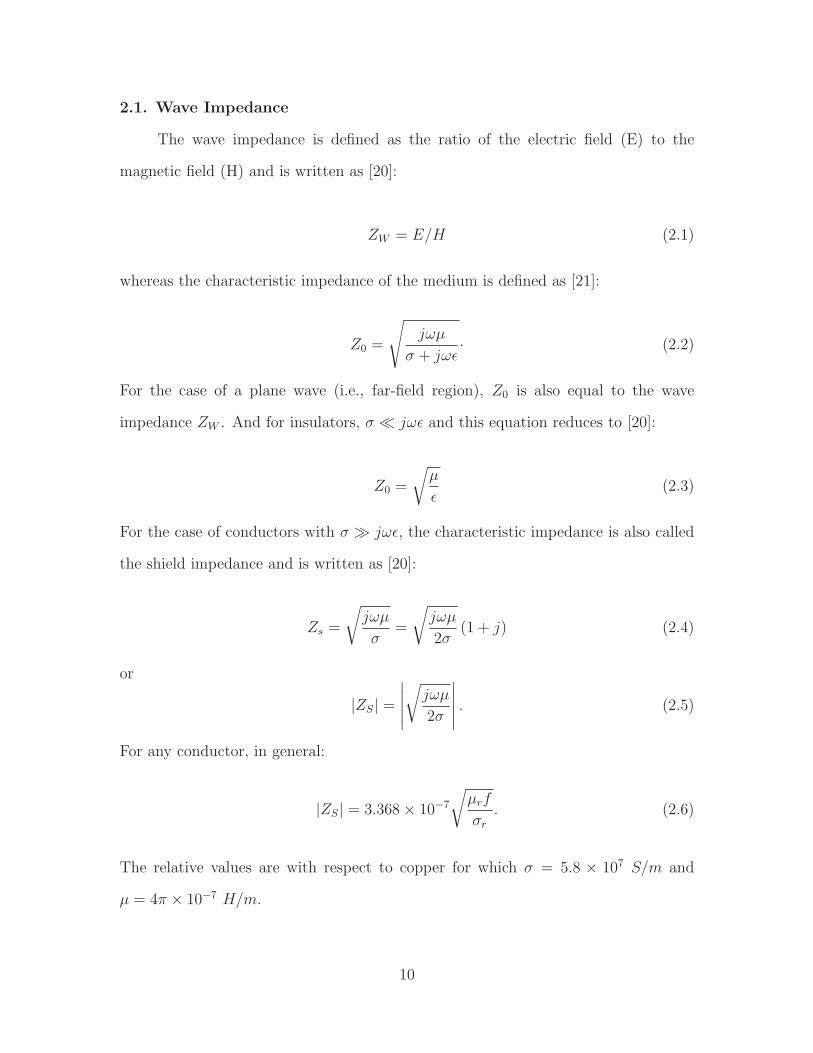
2.1. Wave Impedance
The wave impedance is defined as the ratio of the electric field (E) to the
magnetic field (H) and is written as [20]:
ZW = E/H (2.1)
whereas the characteristic impedance of the medium is defined as [21]:
Z0 =
√
jωµ
σ + jωǫ· (2.2)
For the case of a plane wave (i.e., far-field region), Z0 is also equal to the wave
impedance ZW . And for insulators, σ ≪ jωǫ and this equation reduces to [20]:
Z0 =
√
µ
ǫ(2.3)
For the case of conductors with σ ≫ jωǫ, the characteristic impedance is also called
the shield impedance and is written as [20]:
Zs =
√
jωµ
σ=
√
jωµ
2σ(1 + j) (2.4)
or
|ZS| =
∣
∣
∣
∣
∣
√
jωµ
2σ
∣
∣
∣
∣
∣
. (2.5)
For any conductor, in general:
|ZS| = 3.368× 10⁻⁷
√
µrf
σr
. (2.6)
The relative values are with respect to copper for which σ = 5.8 × 10⁷ S/m and
µ = 4π × 10−7 H/m.
10

Incident
Transmitted
Medium 1
Re!ected
Medium 2
IE
ER
ET
Figure 6. Partial reflection and partial transmissionthrough interface between two media.
2.2. Shielding Effectiveness
Shielding effectiveness is defined as:
SE = 20 logEi
Et
= 20 logHi
Ht
(2.7)
where ‘i’ denotes the incident field and ‘t’ denotes the transmitted field. The shielding
effectiveness for a metallic sheet mainly comprises of two portions. One is the
reflection from the surface which is called the reflection loss and is dependent on
the type of field and the wave impedance. The second is the attenuation of the wave
inside the shield as the transmitted (non-reflected) wave passes through it. This is
called the absorption loss and this mainly depends on the skin depth and the thickness
of the shield. So we can write the total shielding effectiveness of the solid material
shield as:
11

SE = R + A+ B(dB) (2.8)
where R is the reflection loss, A is the absorption loss and B is the correction factor
which accounts for the multiple reflections in thin shields.
2.3. Reflection Loss
Now for the case of reflection, consider the following simple case as shown in
Figure 6. Ei is the electric field intensity of the incident electromagnetic wave at
the boundary of the medium 1 and medium 2. Et is electric field intensity of the
transmitted electromagnetic wave from medium 1 to medium 2 and Er is the Electric
field intensity of the reflected electromagnetic wave from the junction of medium 1
and medium 2 to medium 1. The reflection coefficient can be written as:
Γ =Z2 − Z1
Z2 + Z1
(2.9)
and the transmission coefficient can be written as:
T = 1−Z2 − Z1
Z2 + Z1
=2Z1
Z1 + Z2
. (2.10)
Then
Et = TEi =2Z1
Z1 + Z2
Ei (2.11)
Next, consider the set up for the shielding measurement as shown in Figure 7, and
applying these concepts.
Ei is the incident wave at shield from medium 1 (air)
Es is the wave transmitted inside the shield through boundary 1
ET is the transmitted wave from shield to medium 2 (air)
Ts is the transmission coefficient between shield and medium 1
12

Electric
FieldE
i
ER1
ER2
Impedance Z1
Impedance Z2
Magnetic
FieldH
i
HR1
EZ
Z ZEiS
1
1 2
2=
+
HR2
HZ
Z ZHiS
1
1 2
2=
+
Impedance Z1
EZ
Z ZEST
1
1 2
2=
+
HZ
Z ZHST
1
1 2
2=
+
Figure 7. Partial reflection and transmission at bothboundaries of shield
and T is the transmission coefficient between shield and medium 2.
Now the electric field intensity inside the shield is written as:
Es = TEi =2Zq
Z1 + Zs
Ei (2.12)
and the transmitted electric field through the shield can be written as:
Et = TEs =2Zs
Z1 + Zs
Es (2.13)
or
Et =2Zs
Z1 + Zs
2Z1
Z1 + Zs
Ei =4Z1Zs
Z1 + Zs2Ei. (2.14)
For a plane wave the impedance of air is Z1 = 377 Ω and for conductors ZS ≪ Z1, so
Et =4Zs
Zi
Ei. (2.15)
13

Now defining the reflection loss as:
R = 20 logEi
Et
= 20 log377
4Zs
(2.16)
and using the value of shield impedance, we get the equation for the reflection loss
as:
R = 168 + log
(
σr
µrf
)
dB. (2.17)
2.4. Absorption Loss
The amplitude of the electromagnetic wave decreases exponentially as it passes
through the medium. This happens because the induced currents in the shield
(medium) produce ohmic losses and thus heating of the shield material. Therefore
we can write:
E (H)1= E (H)
0e
−t
δ (2.18)
where E (H)1is the field intensity at a distance ‘t’ inside the shield and E (H)
0is
the incident field intensity on the shield. ‘δ‘ is the skin depth which can be defined
as the distance required for the field to be attenuated to 1
eor 37% of its value and
can be written as:
δ =
√
2
ωµσm =
√
2.6
fµrσr
in (2.19)
where µr, σr are the relative permeability and relative conductivity with respect to
copper.
Now we can write the absorption loss through the shield as:
A = 20 logE0
E1
= 20 log et
δ (2.20)
14

Shield
Medium, Z1
Medium, Z2 Medium, Z
1
Ho
Ht1
Ht2
Hr1
Ht3
Ht5
Ht4
Ht6
Hr2
Hr3
Hr4
Hr5
Hr6
Figure 8. Multiple reflections in thin shield
and
A = 8.69
(
t
δ
)
dB (2.21)
Putting the expression for skin depth in the equation then gives:
A = 3.34t√
fµrσrdB (2.22)
where ‘t’ is the thickness of the shield.
2.5. Correction Factor / Multiple Reflections in Thin Shield
If the shield is thin, then the electromagnetic wave inside the shield is reflected
back from the second boundary and is incident upon the first boundary. Here some
of this wave is transmitted through the first boundary towards the original source
and the rest of the wave is reflected back to the second boundary either to transmit
to the receiver or to reflect again inside the shield as shown in Figure 8.
15

For the case of the electric field, most of the field is reflected from the first
boundary as Z2 ≪ Z1. Therefore, multiple reflections can be neglected for the electric
field. For the case of the magnetic field, most of the wave passes through the first
boundary of the shield as Z2 ≪ Z1. Therefore the effect of multiple reflections needs
to be considered for the magnetic field. The correction factor for the case of the
magnetic field is:
B = 20 log(
1− e−2tδ
)
dB (2.23)
where ‘t’ is the thickness and ‘δ′ is the skin depth for the shield.
16

CHAPTER 3. MEASUREMENTS
The carbon microfiber samples used for this study were the 24k carbon tow
from fiberglast shown in Figure 9. These tows are composed of filaments of diameter
7 µm and are composed of 24000 filaments with a tensile strength of 710 − 750 ksi.
This carbon fiber is used in four different woven patterns for this study.
Figure 9. Carbon microfiber samples [22].
To utilize the carbon microfiber as a shielding material, we assembled the set
up in Figure 10 with a 61 cm × 91 cm aluminum sheet with a thickness of 0.32 cm.
This sheet was cut from the center with the dimension 28 cm × 28 cm making an
aperture in the center of the sheet. The dimensions of the aperture were a little
less than the size of the carbon microfiber samples as the size of the samples was
30 cm×30 cm. Then we used the TDK−HRN−0118 horn antennas as transmitter
17

91 cm
61 cm
30 cm
30
cm
TDK-HRN-0118TDK-HRN-0118
38 cm 38 cm
Network Analyzer
E7051C 100 KHz- 4.5 GHz
Figure 10. S21 measurement setup.
and receiver pair, and the distance between these two antennas was 76 cm. These
antennas are designed for the frequency range 1 − 18 GHz. The network analyzer
used for measurement in this set up was an Agilent E5071C 100 kHz − 4.5 GHz
ENA series network analyzer. We chose the frequency range for the measurements
from 1 GHz to 4 GHz.
Next, we compared the measurements of the two scenarios. One was that there
was nothing in between the antennas, and only the path loss was occurring between
the antennas for the measurement of S21. The other scenario was that the aluminum
sheet with the cut aperture was put in the middle, and then these measurements were
repeated. These measurements are shown in Figure 11. As we can observe from the
measurements that both of these measurements are pretty close to each other, i.e.,
18

1 1.5 2 2.5 3 3.5 4-30
-28
-26
-24
-22
-20
f (GHz)
S2
1 (d
B)
Apertureair
Figure 11. Measurement of path loss of air and openaperture
only a 1 − 2 dB difference. There was only one contradiction to this measurement
at the frequency of 1.1 GHz where the difference between the measurements in
4 dB. Overall we can say that the horn antennas are directing the waves through the
aperture.
The next step in the measurements was to cover the aperture with the samples
and measure S21. This measured S21 should be very much less than S21 measured
earlier with nothing between the antennas and the S21 of the aluminum sheet with the
aperture between the antennas due to the fact that the carbon microfiber is shielding
the signal. Also we covered the aperture with an aluminum sheet and made the
measurement for reference.
These measurement results are shown in the Figure 12, and we can observe from
the figure that the S21 values for all the four samples of carbon microfiber in Figure
9 are in close agreement to each other. Thus we can deduce that the aluminum
sheet and the carbon microfiber is allowing almost the same amount of signal to
19

1 1.5 2 2.5 3 3.5 4-80
-70
-60
-50
-40
f (GHz)
S2
1 (d
B)
3220322132223223Aluminum
Figure 12. Measured S21 for carbon microfiber andaluminum sheets
pass through them or in fact, the carbon microfiber has a shielding similar to a solid
aluminum sheet.
Next, we translated this measured S21 to shielding effectiveness (SE). For this we
need to take into account the path loss which occurred between the two antennas as
we can not take this loss as shielding. So we deducted the path loss earlier measured
Figure 13. Stainless steel enclosure for heating / cooling
20

1 1.5 2 2.5 3 3.5 4
x 109
10
15
20
25
30
35
40
45
50
55
60
f (Hz)
Shie
ldin
g E
!e
ctiv
en
ess
(dB
)
03220
03221
03222
03223
Al
Figure 14. Measured shielding effectiveness
from this S21 measurement for the carbon microfiber and aluminum and ploted the
shielding effectiveness in Figure 14. As we can see from the plot that all the SE values
for the four samples of carbon microfiber follow each other thus depicting that the
woven pattern does not effect the shielding effectiveness. Also the shielding from the
aluminum is following the graphs from the carbon microfiber with the only difference
that it is lower by 2 − 3 dB in some instances. Overall the shielding effectiveness is
the same as the conducting aluminum sheet.
The next setup which we used for both the heating / cooling testing and
shielding is shown in Figure 13 . This setup consisted of a stainless steel metallic
box of size 30.5 cm× 30.5 cm with a height of 41 cm. The top plate of the metallic
enclosure was cut to give it the opening / aperture so that the shielding for the
stainless steel and the carbon microfiber could be measured and compared.
One horn antenna was placed inside the steel enclosure facing out towards the
aperture and the other antenna was placed on the top outside of the enclosure at a
distance of 76 cm as shown in Figure 15. Then we measured S21 with the aperture
covered with the metallic stainless steel sheet and the carbon microfiber samples.
The measured results are shown in the Figure 16. It can be observed from the results
21

Network Analyzer
E7051C 100 KHz- 4.5 GHz
TDK-HRN-0118
31 cm
31 cm
41 cm
Figure 15. Dimensions of the heating / cooling measure-ment setup
that the shielding from the stainless steel and the carbon microfiber samples are in
close agreement throughout the frequency range of 1 GHz to 4 GHz. It can also be
deduced that the a similar shielding effectiveness is observed for all samples.
This same setup is used to test the thermal properties of the carbon microfiber
and steel covering the aperture of the enclosure. Two 100 W bulbs were used inside
1 1.5 2 2.5 3 3.5 4-100
-80
-60
-40
f (GHz)
steel enclosure32213222
S 21 (d
B)
Figure 16. Measurement of S21 in steel enclosure
22

0 50 100 150 200 25020
25
30
35
40
45
50
55
60
65
Time (mins)
Tem
pe
ratu
re °
C
Steel
03220
03222
Figure 17. Temperature rise measurement inside enclo-sure
the enclosure to generate the heat, and the temperature was measured over time.
Figure 17 shows the temperature rise with respect to time and it can be seen that the
temperature in the steel covered enclosure rises earlier than the carbon microfiber
covered enclosure above 45 C. Also the maximum temperature for the carbon
microfiber covered enclosure was 5 C less than the steel covered enclosure.
The temperature fall time for this setup was also measured and is shown in the
Figure 18. Though the time to reach the room temperature was almost the same for
both the cases, the decrease in temperature from the highest point to almost 30 C
was faster in the carbon microfiber covered enclosure. Thus it can be said that the
operating temperature inside the carbon microfiber covered enclosure is always less.
S21 was also measured during these heat/cool cycles but there was no observable
difference in the measurement.
23

0 50 100 15025
30
35
40
45
50
55
60
65
Time (mins)
Tem
pe
ratu
re °
C
Steel
03220
03222
Figure 18. Temperature fall measurement inside enclo-sure
24

CHAPTER 4. SIMULATION OF CARBON MICROFIBER
SHIELD
In a previous chapter we discussed the details about the measurement setup and
the results we get from our shield. In this chapter we will simulate the environment
in the simulation software for electromagnetic, namely, High Frequency Simulation
Software (HFSS) 15.0 and will match the environment and the measurements with
the simulation. This chapter describes the steps to achieve this goal.
4.1. Simulation Setup
For simulation purposes, the actual measurement environment is incorporated
in the design of the simulation. First, the actual horn antenna with the dimensions
width = 23.4 cm, depth = 29 cm and height = 14.5 cm is simulated as shown in the
Figure 19. The material of the antenna is aluminum and the thickness of aluminum is
0.32 cm. The actual TDK−HRN−0118 antenna is designed for the frequency range
14.5 cm
29 cm
23.4 cm
Figure 19. Horn antenna for simulation.
25

Figure 20. Radiation pattern of simulated horn antenna.
from 1 GHz to 18 GHz. But we simulated the antenna only for the frequency range
from 1 GHz to 4 GHz as our measurements are only in this frequency range. The
simulation results for the horn antenna are shown in Figure 20. Thses simulations are
in agreement with the actual antenna specifications as provided by the manufacturer
in the data sheet.
Then we simulated our actual measurement setup by placing two horn antennas
as transmitter and receiver in the simulation setup at a distance of 76 cm as shown
in Figure 21. Both of these antennas are driven by wave ports with one antenna
as a transmitter (source) and the other antenna as a receiver. Also the aluminum
sheet is placed at the center (i.e., at 38 cm from both the transmitter and receiver
antenna. The sheet is cut from the center with the dimension 28 cm×28 cm to make
an aperture at the center, as used in the measurement. The air box containing this
26

38 cm38 cm
91 cm
12 in
12
in
TDK-HRN-0118
Sample under
test
Wave port
Aluminum
Sheet
Wave port
TDK-HRN-0118
61
cm
30 cm
30 cm
Figure 21. Simulation setup.
setup was of size 91.5 cm × 117 cm × 132 cm, and this air box was assigned with
radiation boundary conditions.
4.2. Measurement Results
Then we simulated this setup by covering the aperture both with aluminum
and microfiber. The simulation results with the aperture covered with aluminum are
1 1.5 2 2.5 3 3.5 4
x 109
-60
-50
-40
-30
-20
-10
f (Hz)
|S2
1| (
dB
)
Aperture Open (Measured)Aperture Aluminum (Measured)Aperture Aluminum (Simulated)Aperture Open (Simulated)
Figure 22. Simulation and measured S21 results foraperture and aluminum sheet.
27

1 1.5 2 2.5 3 3.5 4
x 109
-65
-60
-55
-50
-45
-40
-35
Frequency (Hz)
S2
1 (d
B)
conductivity =1000conductivity = 4000conductivity = 10000conductivity = 100000
Figure 23. S21 simulation results for different fiberconductivities.
similar to the measured results, i.e., the transmitted signal S21 for the measured and
simulated environment are in agreement. The S21 results for the simulation are shown
in the Figure 22.
The simulation and measured results show that there is approximately a 2−3 dB
difference for the frequency range and both the results follow each other very closely.
This agreement between these results shows that the simulation environments we are
considering for this project are reliable and a good approximation.
Next, we simulated the environment with the microfiber sheet at the center
covering the aperture. For this purpose, we assumed carbon microfiber as a solid
sheet as the gaps between woven pattern are very small, and it is equivalent to a flat
sheet. The relative permeability µr for carbon microfiber is 1 as it is not a magnetic
material. Also as the electrical property (conductivity) of the carbon microfiber
material is unknown, so we did the parametric simulation for the environment with
28

1 1.5 2 2.5 3 3.5 4
x 109
-65
-60
-55
-50
-45
-40
-35
Frequency (Hz)
S2
1 (d
B)
conductivity =1000
conductivity = 4000
conductivity = 10000
conductivity = 100000
Measured S21
for sample 0323
Figure 24. Comparison of S21 simulation results fordifferent fiber conductivities.
conductivity as the variable. The idea is that the shielding effectiveness depends on
the material property conductivity, so the simulated S21 values should be different for
different conductivity values. Utilizing this idea we did the simulation for the value
of conductivity from 100 S/m to 107 S/m. The S21 results for different values of
conductivity are shown in the Figure 23. Note that not all the simulation results are
shown to decrease the clutter in the plot.
These S21 results were then compared to the measured S21 results. By this
comparison, we estimated the value of conductivity for the carbon microfiber. To
further strengthen this deduction of carbon microfiber conductivity, the comparison
of these measured and simulated results with the analytical shielding effectiveness
values for this conductivity is presented in the next chapter. Here the closest results
are compared to carbon microfiber sample 0323 and are shown in the Figure 24. The
S21 values for these simulations remain almost the same for the higher conductivity
values. In the 104 range, the S21 values start to decrease meaning a decrease in the
shielding. Here the comparison of the measured S21 values of sample 0323 with four
different conductivities is done.
29

1 1.5 2 2.5 3 3.5 4
x 109
10
15
20
25
30
35
Frequency (Hz)
SE (d
B)
conductivity =1000conductivity = 2000conductivity = 4000
Figure 25. Simulated shielding effectiveness for differentconductivity values.
To convert these S21 values, we need to consider the path loss effect for this
setup. The S21 values for the aperture case are used for evaluating the shielding
effectiveness. The S21 values for the open aperture are in agreement with the values
of S21 without any sheet between the transmitter and receiver antennas and the
analytical value for path loss. The shielding effectiveness for the simulation case is
shown in the Figure 25.
30

CHAPTER 5. ANALYTICAL FORMULATION AND
COMPARISON OF RESULTS
For analytical shielding calculations, the theory as described in Chapter 2 is used
to calculate the analytical shielding for the carbon microfiber. For this purpose, the
carbon microfiber‘s woven structure is assumed as a plain sheet. Thus the equations
derived previously are utilized to calculate the shielding effectiveness analytically for
the operating frequency range of 1 GHz to 4 GHz.
The conductivity of the material is unknown, so we used simulation results and
calculated the shielding for different conductivity values whose S21 values were in
agreement with the measured results. For the purpose of calculating the analytical
shielding, we are taking into account the reflection loss of electromagnetic shielding.
The absorption loss (A) and correction factor (B) are neglected for this particular
case because of the thin nature of the carbon microfiber material.
1 1.5 2 2.5 3 3.5 40
5
10
15
20
25
f (GHz)
Imp
ed
ance
(Oh
m)
0322103222
Figure 26. Carbon microfiber impedance for 03221 and03222 from measured S21 results.
31

1 1.5 2 2.5 3 3.5 4
x 109
20
25
30
35
40
Frequency (Hz)
SE (d
B)
800100020004000
Figure 27. Analytical shielding effectiveness for differentconductivity values.
The reason for neglecting the absorption loss (A) is that it has a diameter of
7 µm for single filament which is comparable to the skin depth of the signal. Thus we
can ignore the absorption loss as the signal does not effectively propagate inside the
material for a sufficient distance for absorption loss to be of a significant value. Also
the impedance value of the medium (carbon microfiber) is quite low in comparison to
the free space impedance as calculated from the measured S21 results and is shown
in the Figure 26.
Thus the main shielding happens due to reflection on the first boundary as in
a metallic shield. The correction factor is only needed for the case of the magnetic
field where the reflection happens at the second boundary. We can ignore the term
B for a plane wave and for the electric field because of high reflection loss and very
small correction factor. Thus the analytical shielding results for different conductivity
values are calculated and they only comprise of the reflection loss. These results are
shown in Figure 27.
32
f (GHz)
1 1.5 2 2.5 3 3.5 4
SE (d
B)
10
20
30
40
50
60
Meas. SE (0323)Analytical @ 1000Analytical @ 1500Analytical @ 2000Analytical @ 4000Sim. @ 1000Sim. @ 1500Sim. @ 2000Sim. @ 4000
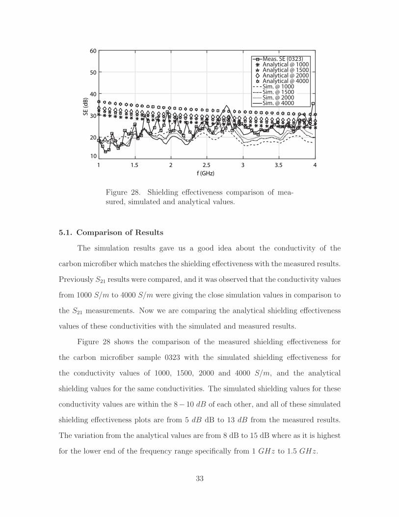
Figure 28. Shielding effectiveness comparison of mea-sured, simulated and analytical values.
5.1. Comparison of Results
The simulation results gave us a good idea about the conductivity of the
carbon microfiber which matches the shielding effectiveness with the measured results.
Previously S21 results were compared, and it was observed that the conductivity values
from 1000 S/m to 4000 S/m were giving the close simulation values in comparison to
the S21 measurements. Now we are comparing the analytical shielding effectiveness
values of these conductivities with the simulated and measured results.
Figure 28 shows the comparison of the measured shielding effectiveness for
the carbon microfiber sample 0323 with the simulated shielding effectiveness for
the conductivity values of 1000, 1500, 2000 and 4000 S/m, and the analytical
shielding values for the same conductivities. The simulated shielding values for these
conductivity values are within the 8− 10 dB of each other, and all of these simulated
shielding effectiveness plots are from 5 dB dB to 13 dB from the measured results.
The variation from the analytical values are from 8 dB to 15 dB where as it is highest
for the lower end of the frequency range specifically from 1 GHz to 1.5 GHz.
33
1 1.5 2 2.5 3 3.5 4
x 109
10
15
20
25
30
35
40
45
50
Frequency (Hz)
SE (d
B)
Carbon Micro!ber Measured 0323
Sim cond = 2000
analytical cond = 2000
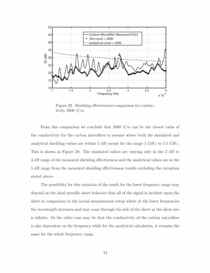
Figure 29. Shielding effectiveness comparison for conduc-tivity 2000 S/m.
From this comparison we conclude that 2000 S/m can be the closest value of
the conductivity for the carbon microfiber to assume where both the simulated and
analytical shielding values are within 5 dB except for the range 1 GHz to 1.5 GHz.
This is shown in Figure 29. The simulated values are varying only in the 2 dB to
3 dB range of the measured shielding effectiveness and the analytical values are in the
5 dB range from the measured shielding effectiveness results excluding the exception
stated above.
The possibility for this variation of the result for the lower frequency range may
depend on the ideal metallic sheet behavior that all of the signal is incident upon the
sheet in comparison to the actual measurement setup where at the lower frequencies
the wavelength increases and may come through the side of the sheet as the sheet size
is infinite. Or the other case may be that the conductivity of the carbon microfiber
is also dependent on the frequency while for the analytical calculation, it remains the
same for the whole frequency range.
34
5.2. Conclusions
This research work focuses on the electromagnetic shielding properties of the
carbon microfiber material. For this purpose, measurement of shielding effectiveness,
simulation of the measurement environment in HFSS v.15.0, and analytical derivation
have been investigated. The effect of carbon microfiber material on heating /cooling
of a metallic enclosure has also been studied.
The results of the shielding effectiveness for carbon microfiber showed good
agreement with the metallic shield thus making the carbon microfiber a suitable
contender for the replacement of the metallic shield in EM shielding applications.
A shielding effectiveness of about 25 dB for the proposed setup was observed for
the aluminum sheet and the carbon microfiber shield. The simulation results and
the measurements showed good agreement for this measurement setup. This setup
hence verified the reliability of the simulations with the measurements. Moreover, the
shielding effectiveness for the ideal carbon microfiber shield are computed analytically
and are compared with the simulation and measurement results. It is observed
that there is minor deviation (about 5 dB) in the analytical results because of the
assumption of the ideal shield. As the actual setup included antennas, free space and
finite sheet in the chamber.
Furthermore, heating up and cooling down time of a metallic chamber was
observed, and it was noted that the metallic enclosure heated less with its one wall
replaced with carbon microfiber. Also, the enclosure cooled down faster than the
complete metallic enclosure. This heating/cooling property gives an added advantage
in comparison to the metallic shields and enclosures. The results of the shielding
effectiveness showed that the carbon microfiber is capable of blocking an EM wave
over the range from 1 GHz to 4 GHz. These composite materials have a shielding
property that is same as that of metals but are flexible and light weight as compared
35

to the metals. Carbon microfibers also have an anti-corrosion property. Thus, the
carbon microfiber can be used in the medical appliances industry, electronic devices,
and aircraft for the shielding of the EM waves as well as for the cooling/heating of
the electronic equipment.
36

BIBLIOGRAPHY
[1] Yang S., Lozano K., Lomeli A., Foltz H. D., Jones R., “Electromagnetic interfer-
ence shielding effectiveness of carbon nanofiber/LCP composites”, Composites:
Part A, Vol. 36, pp. 691-697, 2005.
[2] Chung D. D. L., “Electromagnetic interference shielding effectiveness of carbon
materials”, Elsevier Science Ltd., Carbon, Vol. 39, pp. 279-285, 2001.
[3] Xing L., Liu J., Ren S., “Study on electromagnetic property of short carbon
fibers and its application to radar absorbing”, Cailiao Gongcheng/J Mater Eng.,
pp. 1921, 1998.
[4] Rupprecht L., Hawkinson C., “Conductive plastics for medical applications”.
Medical Device & Diagnostic Industry, 1999.
[5] Tan S., Zhang M., Zeng H., “Electroconductive polymer composite for shielding
EMI”, Cailiao Gongcheng/J Mater Eng., pp. 69, 1998.
[6] Kolyer J. M., “Environmentally resistant, conductive adhesive bonds for radio
frequency (RF) shielding”, Proc. 43rd Int. SAMPE Symp. Exhib., Covina,
California, USA, vol. 43, pp. 810822, 1998.
[7] Olivero D. A., Radford D. W., “Multiple percolation approach to EMI shielding
composites incorporating conductive fillers”, Reinforced Plastics & Composites,
pp. 674690, 1998.
[8] Sau K. P., Chaki T. K., Chakraborty A., Khastgir D., “ Electromagnetic
interference shielding by carbon black and carbon fibre filled rubber composites”,
Plastics Rubber & Composites Processing & Applications, pp.291-297, 1997.
37

[9] Miyashita K., Imai Y., “Study on shielding materials for electromagnetic waves”,
Int. Progr. Urethanes, pp. 195-218, 1993.
[10] Ma C. M., Hu A. T., Chen D.K. , “Processability, electrical and mechanical
properties of EMI shielding ABS composites”, Polymers & Polymer Composites,
pp. 93-99, 1993.
[11] Li L., Chung D. D. L., “Electrical and mechanical properties of electrically
conductive polyethersulfone composite”, Composites, pp. 215-224, 1994.
[12] Li L., Chung D. D. L., “Effect of viscosity on the electrical properties of
conducting thermoplastic composites made by compression molding of a powder
mixture”, Polym. Composites, pp. 46772, 1993.
[13] Kelly A., “Composites in context”, Compos Sci Technology, Vol. 23, Issue. 3, pp.
171-199, 1985.
[14] Hull D., Clyne T. W., “An Introduction to Composite Materials”, Second edition,
Cambridge University Press, 1996.
[15] Pilato L. A., Michno M. J., “Advanced Composite Material”, Berlin: Springer-
Verlag, 1994.
[16] Gay D., Hoa S. V., Tsai S. W., “Composite materials: design and applications”,
Boca Raton, FL: CRC Press, 2003.
[17] Shui X., Chung D. D. L., “Nickel filament polymer matrix composites with low
surface impedance and high electromagnetic interference shielding effectiveness”,
J Electron Mater, pp. 928-934, 1997.
38

[18] Luo X., Chung D. D. L., “Electromagnetic interference shielding reaching 130 dB
using flexible graphite”, Elsevier Science Ltd, Carbon 34,vol. 10, pp. 1293-1294,
2001.
[19] [online] www.ansoft.com
[20] Henry W. Ott, “Electromagnetic Compatibility Engineering“, John Wiley &
sons, 2009.
[21] Hayt, W. H. Jr. “Engineering Electromagnetics“, McGraw Hill, 8th. ed. New
York, 2012
[22] [online] www.fibreglast.com
[23] [online] www.jdr.sagepub.com
[24] [online] www.nanotechweb.org/cws/article/lab/58172
[25] [online] www.spacedaily.com
39