carbonated beverage co2 storage systems - aspe...
TRANSCRIPT

November 2013 Joe McElvaney 1
Carbonated Beverage CO2 Storage Systems

November 2013 Joe McElvaney 2
MOLECULAR FORMULA: CO2
MOLECULAR WEIGHT (MW) = 44
CAS #: 124-38-9
APPEARANCE: Colorless
ODOR: Odorless, but with a slightly pungent odor and biting or acidic taste may be noticed at high concentrations

November 2013 Joe McElvaney 3
SPECIFIC GRAVITY (gas)(Air=1): 1.522 @ 70ºF and 1 atm.
SPECIFIC VOLUME: 8.741 cu. ft/lb @ 70ºF and 1 atm.
BOILING POINT: -109.3ºF (sublimation temperature)

November 2013 Joe McElvaney 4
HAZARDS: GENERAL: Asphyxiant; contact with liquid or solid
may cause frostbite. ROUTES OF EXPOSURE: Inhalation (gas); skin and
eyes (liquid or solid phase). TARGET ORGANS: Respiratory system; central
nervous system; heart. EXPOSURE DATA: NIOSH IDLH: 40,000 ppm TLV:
5,000 ppm

November 2013 Joe McElvaney 5
O2 = 7.3%O2 = 12.5%O2 = 19.5%O2 = 20%0 ppm
100%65%40%7%4%3%0%
1,000,000 ppm 650,000 ppm 70,000 ppm 40,000 ppm 30,000 ppm 5,000 ppm
8 min - 100% fatal
6 min 50% fatal4 min Recovery with Treatment
Increased respiration impaired judgment
coordination and perception
O2 = 19.5% Minimum level
allowed by OSHA
considered IDLH
IDLHStel (15mon)ACGIH
TLV-TWAACGIH

November 2013 Joe McElvaney 6
What Carbon Dioxide Can Do To You

Code sections referenced in the PowerPoint are from the 2012 IFC unless notes
November 2013 Joe McElvaney 8
Chapter 2
COMPRESSED GAS SYSTEM. An assembly of equipment designed to contain, distribute or transport compressed gases. It can consist of a compressed gas container or containers, reactors and appurtenances, including pumps, compressors and connecting piping and tubing.
CRYOGENIC FLUID. A fluid having a boiling point lower than -130°F at 14.7 pounds per square inch atmosphere (psia) (an absolute pressure of 101.3 kPa).

November 2013 Joe McElvaney 9
So is CO2 a compressed gas or a cryogenic fluid ?
November 2013 Joe McElvaney 10
Chapter 2 HAZARDOUS MATERIALS. Those chemicals or
substances which are physical hazards or health hazards as defined and classified in this chapter, whether the materials are in usable or waste condition.

November 2013 Joe McElvaney 11
Chapter 2
PHYSICAL HAZARD. A chemical for which there is evidence that it is a combustible liquid, cryogenic fluid, explosive, flammable (solid, liquid or gas), organic peroxide (solid or liquid), oxidizer (solid or liquid), oxidizing gas, pyrophoric (solid, liquid or gas), unstable (reactive) material (solid, liquid or gas) or water-reactive material (solid or liquid).

November 2013 Joe McElvaney 12
Chapter 2
HEALTH HAZARD. A classification of a chemical for which there is statistically significant evidence that acute or chronic health effects are capable of occurring in exposed persons. The term “health hazard” includes chemicals that are toxic, highly toxic and corrosive.

November 2013 Joe McElvaney 13
So is CO2 a health or physical hazard ?
So can we use Chapter 50 ?

November 2013 Joe McElvaney 14
Chapter 53
5301.1 Scope. Storage, use and handling of compressed gases in compressed gas containers, cylinders, tanks and systems shall comply with this chapter, including those gases regulated elsewhere in this code. Partially full compressed gas containers, cylinders or tanks containing residual gases shall be considered as full for the purposes of the controls required.

November 2013 Joe McElvaney 15
Characteristics of DOT Cylinders
They normally come in sizes form 10 pound to 100 pounds
The cylinders can be rated as high as 1800 psi
Are normally filled at a bulk gas suppliers place of business
Filling and corresponding size that the industry gives these
vessels is based on the weight of the liquid CO2 they hold. (a 10 pound cylinder is filled with 10 pounds of liquid CO2)

November 2013 Joe McElvaney 16
Characteristics of DOT Cylinders They are transported to businesses for use in
beverage systems
Are typically connected to the beverage system by employees of the business selling the beverages
Change out frequency varies based on size of tank and usage.
Typically spare cylinders are kept on hand to replace empty cylinders.

November 2013 Joe McElvaney 17
Characteristics of DOT Cylinders
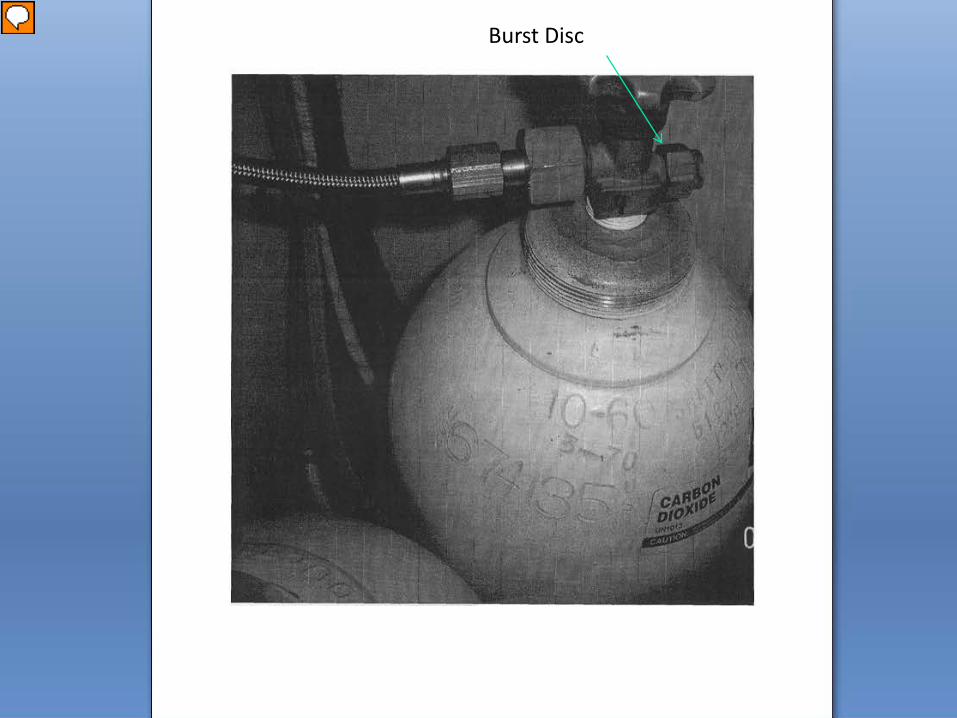
They are equipped with a burst disc that protects the cylinder from over pressurization.
Burst disc or rupture disc have a thin metallic disc
designed to fail at a given pressure. Installation of a burst disc of the proper set pressure is
the responsibility of certified DOT cylinder testing shops and is based on the cylinders maximum designed working pressure.
.

November 2013 Joe McElvaney 18
DOT CO2 Cylinders
November 2013 Joe McElvaney 19
Burst Disc
November 2013 Joe McElvaney 20
Characteristics of ASME Vessels
All ASME (American Society for Mechanical Engineers) certified cylinders are required to have a Data Plate permanently attached to the cylinder or a frame that is permanently attached to the cylinder.

November 2013 Joe McElvaney 21
Characteristics of ASME Vessels
The information provided on the Data plate includes
ASME Code Symbol Stamp
National Board Registration Number
Cylinder Manufacturer
The Maximum Allowable Working Pressure of the tank or MAWP

November 2013 Joe McElvaney 22
Characteristics of ASME Vessels Inspection should include verifying the cylinder is
fitted with the proper safety device. It should be noted that some older tanks have a
maximum allowable working pressure of 287 psi. It is not uncommon for these cylinders to be improperly fitted with a 300 psi safety device.
November 2013 Joe McElvaney 23
Characteristics of ASME Vessels The code required primary safety device is a spring
loaded safety device. This type of device is designed to reseat within a percentage of the set pressure stamped on the device.
The secondary device is a burst disc “that is a disc
that burst or breaks open at a set pressure”. These disc do not reseat and are much like a pop top on a beverage container.

November 2013 Joe McElvaney 24
ASME Data Plate

November 2013 Joe McElvaney 25
Maximum Pressure
ASME Certification Symbol

November 2013 Joe McElvaney 26
Relief Valve
Burst Disc
Fill Connection
Vent Circuit

November 2013 Joe McElvaney 27
5303.3.4 Arrangement. Pressure relief devices shall be arranged to discharge upward and unobstructed to the open air in such a manner as to prevent any impingement of escaping gas upon the container, adjacent structures or personnel.

November 2013 Joe McElvaney 28
5303.4.3 Piping systems. Piping systems shall be marked in accordance with ASME A13.1. Markings used for piping systems shall consist of the content’s name and include a direction-of-flow arrow. Markings shall be provided at each valve; at wall, floor or ceiling penetrations; at each change of direction; and at a minimum of every 20 feet (6096 mm) or fraction thereof throughout the piping run.

November 2013 Joe McElvaney 29
SECTION 5307 COMPRESSED GASES NOT OTHERWISE REGULATED 5307.2 Ventilation. Indoor storage and use areas
and storage buildings shall be provided with mechanical exhaust ventilation or natural ventilation in accordance with the requirements of Section 5004.3 or 5005.1.9. When mechanical ventilation is provided, the systems shall be operational during such time as the building or space is occupied.

November 2013 Joe McElvaney 30
NFPA 55, 2010 Edition
1.1 Scope. 1.1.1 Applicability. This code shall apply to
the installation, storage, use, and handling of compressed gases and cryogenic fluids in portable and stationary containers, cylinders, equipment, and tanks in all occupancies.
November 2013 Joe McElvaney 31
NFPA 55, 2010 Edition
6.7* Employee Alarm System. Where required by government regulations, an employee alarm system shall be provided to allow warning for necessary emergency action as called for in the emergency action plan required by 4.2.1.1, or for reaction time for safe egress of employees from the workplace or the immediate work area, or both.

November 2013 Joe McElvaney 32
NFPA 55, 2010 Edition 6.11 Hazard Identification Signs. 6.11.1 Location. Hazard identification signs shall be
placed at all entrances to locations where compressed gases are produced, stored, used, or handled in accordance with NFPA704, Standard System for the Identification of the Hazards of Materials for Emergency Response.
6.11.1.1 Ratings shall be assigned in accordance with NFPA 704.
6.11.1.2 The authority having jurisdiction shall be permitted to waive 6.11.1 where consistent with safety.

November 2013 Joe McElvaney 33
NFPA 55, 2010 Edition 6.15 Ventilation. Indoor storage and use areas and storage
buildings for compressed gases and cryogenic fluids shall be provided with mechanical exhaust ventilation or natural ventilation, where natural ventilation can be shown to be acceptable for the material as stored.
6.15.1 Mechanical Ventilation. Where mechanical ventilation is provided, the system shall be operational during the time the building or space is occupied.
6.15.3 Mechanical Ventilation Rate. Mechanical ventilation shall be at a rate of not less than 1 ft3/min/ft2 of floor area over the area of storage or use.
6.15.4 Continuous Operation. Systems shall operate continuously unless an alternative design is approved by the AHJ.

November 2013 Joe McElvaney 34
NFPA 55, 2010 Edition 6.15.5 Shutoff Controls. Where powered
ventilation is provided, a manual shutoff switch shall be provided outside the room in a position adjacent to the principal access door to the room or in an approved location.
6.15.6 Manual Shutoff Switch. The switch shall be the breakglass or equivalent type and shall be labeled as follows: WARNING: VENTILATION SYSTEM EMERGENCY SHUTOFF
Do you need this for CO2, remember the hazards
November 2013 Joe McElvaney 35
NFPA 55, 2010 Edition 6.15.7 Inlets to the Exhaust System. 6.15.7.1 The exhaust ventilation system design shall
take into account the density of the potential gases released.
6.15.7.2 For gases that are heavier than air, exhaust shall be taken from a point within 12 in. of the floor.
6.15.7.3 For gases that are lighter than air, exhaust shall be taken from a point within 12 in. of the ceiling.

November 2013 Joe McElvaney 36
NFPA 55, 2010 Edition
6.15.8 Floor Level Exhaust. The location of both the exhaust and inlet air openings shall be designed to provide air movement across all portions of the floor or room to prevent the accumulation of vapors.
6.15.9 Recirculation of Exhaust. Exhaust ventilation shall not be recirculated within the room or building if the cylinders, containers, or tanks stored are capable of releasing hazardous gases
November 2013 Joe McElvaney 37
NFPA 55, 2010 Edition
6.15.10 Ventilation Discharge. Ventilation systems shall discharge a minimum of 50 ft from intakes of air-handling systems, air-conditioning equipment, and air compressors.
6.15.11 Air Intakes. Storage and use of compressed gases shall be located not less than 50 ft from air intakes. For material-specific requirements, see Sections 7.4 through 7.10.
May not be able to get this due to the size of building / roof

November 2013 Joe McElvaney 38
NFPA 55, 2010 Edition 7.1.2 Small Insulated Liquid Carbon Dioxide
Systems. Small insulated liquid carbon dioxide systems shall be in accordance with Chapter 13.

November 2013 Joe McElvaney 39
NFPA 55, 2010 Edition
13.1 General. The storage, use, and handling of liquid carbon dioxide in insulated systems shall be in accordance with the provisions of Chapter 13 and Chapters 1 through 7 as applicable.

November 2013 Joe McElvaney 40
NFPA 55, 2010 Edition 13.1.1* Pressure Relief Devices. Containers used
for liquid carbon dioxide shall be equipped with pressure relief devices piped from the uppermost part of the containers and communicating with the vapor space.
November 2013 Joe McElvaney 41
NFPA 55, 2010 Edition 13.1.1.2 Vent Pipe Systems. Pressure relief
devices shall be piped to the outdoors where the discharge will not impinge on the structure, personnel, or means of egress and will not create a hazardous concentration of carbon dioxide.
13.1.1.2.3 Vent piping systems serving pressure relief devices shall be designed to prevent backflow restrictions exceeding 10 percent backpressure on the pressure relief device under full flow conditions.

November 2013 Joe McElvaney 42
NFPA 55, 2010 Edition 13.1.3 Piping Systems. 13.1.3.1 Carbon dioxide piping shall be located and
supported to protect against damage from strain on piping and fittings; the effects of expansion, contraction, and vibration; mechanical damage; and heat sources.
13.1.3.2 Piping, tubing, and hoses and fittings shall be designed to a bursting pressure of at least four times the system design pressure.
13.1.4* Materials of Construction. Materials of construction shall be employed for potential exposure to a temperature of −109.3°F.

November 2013 Joe McElvaney 43
Fill Systems
The most common system employs a permanently installed vessel, and outdoor-mounted CO2 fill box.
The fill line and vent line join the vessel to the
outdoor fill box.

November 2013 Joe McElvaney 44

November 2013 Joe McElvaney 45

November 2013 Joe McElvaney 46

November 2013 Joe McElvaney 47
Fill Connection
Low Pressure CO2 gas line

November 2013 Joe McElvaney 48
Fill and vent circuit wall penetrations must be sealed to prevent CO2 entry back in the building
Sealed enetration
Note vent line not connected

November 2013 Joe McElvaney 49
Fill Line
Vent Line

November 2013 Joe McElvaney 50
NFPA 55, 2010 Edition
13.2.2* Rooms or areas where container systems are filled and used indoors or in enclosed outdoor locations shall be provided with a gas detection and alarm system that is capable of detecting and notifying the building occupants of a gas release that creates carbon dioxide vapors in excess of its PEL.
13.2.2.1* Activation of the gas detection system shall initiate an audible alarm within the room or area in which the system is installed.

November 2013 Joe McElvaney 51
O2 = 7.3%O2 = 12.5%O2 = 19.5%O2 = 20%0 ppm
100%65%40%7%4%3%0%
1,000,000 ppm 650,000 ppm 70,000 ppm 40,000 ppm 30,000 ppm 5,000 ppm
8 min - 100% fatal
6 min 50% fatal4 min Recovery with Treatment
Increased respiration impaired judgment
coordination and perception
O2 = 19.5% Minimum level
allowed by OSHA
considered IDLH
IDLHStel (15mon)ACGIH
TLV-TWAACGIH

November 2013 Joe McElvaney 52
NFPA 55, 2010 Edition 13.2.2.3 Activation of the gas detection system shall
sound a local alarm to notify persons responsible for system operation of a hazard condition in the area in which the system is installed.

November 2013 Joe McElvaney 53
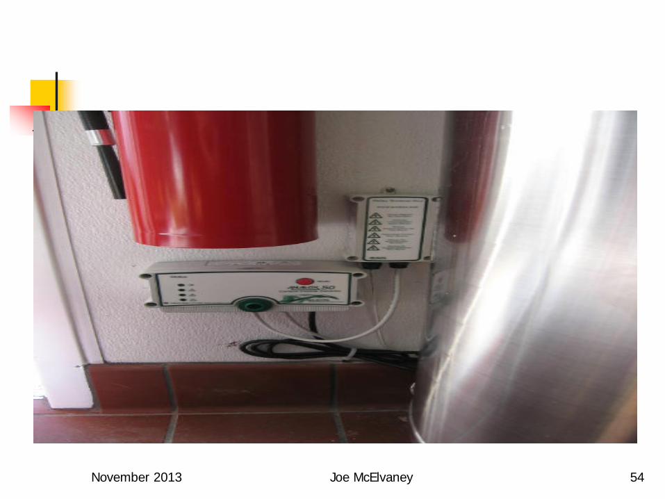
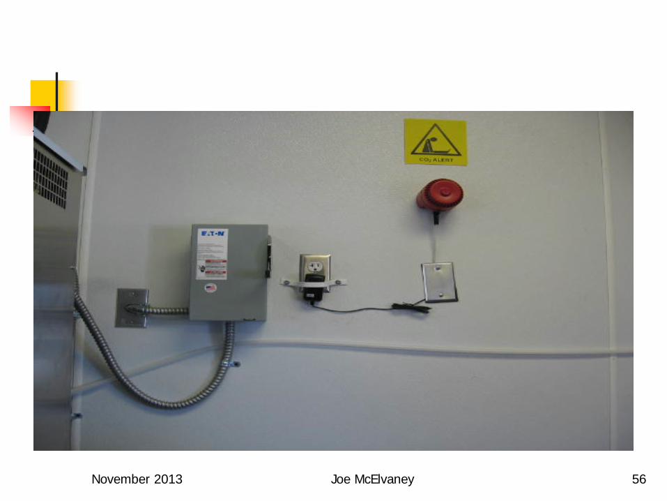
No refernce to NFPA 72, ADA and only audible alarm in room where vessels are storage/used
Phx has a policy that requires two notification
devices rated at 100 cd / 75dba. One in the room where the ASME vessel is stored
and the other in a common space
November 2013 Joe McElvaney 54

November 2013 Joe McElvaney 55
November 2013 Joe McElvaney 56

November 2013 Joe McElvaney 57

November 2013 Joe McElvaney 58

November 2013 Joe McElvaney 59
NFPA 55, 2010 Edition
13.2.3 A warning sign shall be posted at the entrance to the building, room, enclosure, or confined area where the container is located
13.2.3.1 The warning sign shall be at least 8 in. wide and 6 in. high and state the following:
CAUTION — CARBON DIOXIDE GAS.
Ventilate the area before entering. A high carbon dioxide (CO2) gas
concentration in this area can cause suffocation.

November 2013 Joe McElvaney 60

November 2013 Joe McElvaney 61

November 2013 Joe McElvaney 62
NFPA 55, 2010 Edition
13.3 Small Insulated Liquid Carbon Dioxide Outdoor Systems.
13.3.1 Container systems located in enclosed spaces shall be in accordance with Section 13.2 for indoor systems.
13.3.1.1* Aboveground outdoor locations shall not be required to be provided with a gas detection and alarm system in accordance with 13.2.2 where the system is unenclosed
November 2013 Joe McElvaney 63
NFPA 55, 2010 Edition 13.3.1.1.1 To be considered unenclosed, enclosures
constructed to limit access or otherwise provide a visual or architectural barrier for the installation shall be constructed in accordance with the requirements in 6.5.2 for weather protection or with the following:
(1) The enclosure shall be constructed without a roof or overhead cover.
(2) Supports and walls shall not obstruct more than three sides nor more than 75 percent of the perimeter of the storage or use area with 25 percent of the perimeter be in open to the atmosphere.

November 2013 Joe McElvaney 64
What about a service yard or a trash enclosure does this meet the requirement for outside installation?

November 2013 Joe McElvaney 65

November 2013 Joe McElvaney 66

November 2013 Joe McElvaney 67
November 2013 Joe McElvaney 68

November 2013 Joe McElvaney 69

November 2013 Joe McElvaney 70
Drink-thu Soda Machine

November 2013 Joe McElvaney 71

November 2013 Joe McElvaney 72
NFPA 55, 2010 Edition
13.3.1.1.2 Enclosures that do not meet the requirements of 13.3.1.1 shall be permitted when constructed in accordance with the following:
(1) The enclosure shall be constructed without a roof or overhead cover.
(2) Continuous mechanical exhaust ventilation shall be provided

November 2013 Joe McElvaney 73
NFPA 55, 2010 Edition 13.3.1.1.2.1 Where mechanical exhaust ventilation
is provided, it shall be in accordance with the following:
(1) The exhaust system shall be installed in
accordance with the requirements of the mechanical code.
(2) The exhaust system shall be designed to consider
the density of the potential vapors released with exhaust taken from a point within 12 in. of the floor.

November 2013 Joe McElvaney 74
NFPA 55, 2010 Edition
13.3.1.1.2.1 (3) The location of both the exhaust and the inlet air
openings shall be designed to provide air movement across all portions of the enclosure to prevent the accumulation of vapors.
(4) The rate of exhaust ventilation shall be not less
than 1 ft3/min per square foot of floor area within the enclosure

November 2013 Joe McElvaney 75

November 2013 Joe McElvaney 76

November 2013 Joe McElvaney 77

November 2013 Joe McElvaney 78
November 2013 Joe McElvaney 79
November 2013 Joe McElvaney 80
November 2013 Joe McElvaney 81

November 2013 Joe McElvaney 82

November 2013 Joe McElvaney 83

November 2013 Joe McElvaney 84

November 2013 Joe McElvaney 85

November 2013 Joe McElvaney 86
Questions ?
Joe McElvaney 602-262-7755 Office 602-316-3347 Cell