carburizing -...
TRANSCRIPT

Carburizing
Microstructures and Properties
Geoffrey Parrish
Contents
Preface to First Edition........................................................................v
Preface to Second Edition .................................................................vii
Introduction and Perspectives ............................................................1Why Carburize Case-Harden? ........................................................................1Variability ........................................................................................................3Laboratory Tests ..............................................................................................3Design Aspects ................................................................................................4Case-Depth Specifications ..............................................................................7
Chapter 1: Internal Oxidation..........................................................11Factors Promoting Internal Oxidation .........................................................11The Internal Oxidation Process ....................................................................13Effect on Local Microstructure ....................................................................18Influence on Material Properties ..................................................................23Measures to Eliminate or Reduce Internal Oxidation.................................30Summary ........................................................................................................33
Internal Oxidation.......................................................................................33High-Temperature Transformation Products............................................33
Chapter 2: Decarburization ..............................................................37Decarburization Processes ............................................................................37Testing............................................................................................................41Influence on Material Properties ..................................................................43Control of Decarburization ...........................................................................47Summary ........................................................................................................47
Chapter 3: Carbides ...........................................................................51Chemical Composition..................................................................................51Massive, Network, and Dispersed Carbides ................................................53The Formation of Carbides ...........................................................................60The Effect of Network and Dispersed Carbides on Properties ..................62Globular Carbide Dispersions and Film Carbides.......................................69
Globular Carbides and Heavy Dispersions ..............................................69Film Carbides..............................................................................................70The Effect of Globular and Film Carbides on Properties ........................70
Summary ........................................................................................................73
Chapter 4: Retained Austenite .........................................................77Austenite Formation......................................................................................77Austenite in the Microstructure....................................................................81Effect on Material Properties........................................................................81
iii

Control of Retained Austenite ......................................................................93Summary ........................................................................................................94
Chapter 5: Influential Microstructural Features ..........................99Grain Size ......................................................................................................99
Evaluation of Grain Size..........................................................................100Effect of Grain Size on Properties ..........................................................104
Microcracking..............................................................................................107Factors Influencing Microcracking .........................................................108
Microsegregation.........................................................................................113Formation of Microsegregation ...............................................................113Effects of Microsegregation on Properties .............................................117
Nonmetallic Inclusions ...............................................................................119Origin of Nonmetallic Inclusions ............................................................119Effects of Nonmetallic Inclusions ...........................................................121Consequences of Producing Clean Steels ...............................................128
Summary ......................................................................................................129Grain size ..................................................................................................129Microcracks ..............................................................................................129Microsegregation......................................................................................130Nonmetallic Inclusions ............................................................................130
Chapter 6: Core Properties and Case Depth................................135Core Factors.................................................................................................135
Core Hardenability ...................................................................................135Core Microstructure and Hardness..........................................................140Core Tensile Properties............................................................................140Core Toughness ........................................................................................143Effects of Core Properties........................................................................145
Case Factors.................................................................................................148Case Hardenability ...................................................................................149Case Carbon Content................................................................................150Case Depth ................................................................................................155
Quenching Methods ....................................................................................164Distortion .....................................................................................................164Summary ......................................................................................................165
Core Properties .........................................................................................165Case Depth ................................................................................................167Case Carbon..............................................................................................168
Chapter 7: Postcarburizing Thermal Treatments.......................171Tempering ....................................................................................................171
Tempering Reactions ...............................................................................171Effects of Tempering................................................................................175Additional Process Factors ......................................................................183
Refrigeration................................................................................................186Summary ......................................................................................................194
Tempering .................................................................................................194Refrigeration .............................................................................................195
Chapter 8: Postcarburizing Mechanical Treatments .................199Grinding .......................................................................................................199
Grinding Action........................................................................................199
iv

Grinding Burns and Cracks......................................................................200Effect of Grinding Variables ...................................................................203Residual Stresses Caused by Grinding ...................................................207Effect of Grinding on Fatigue Strength ..................................................208
Roller Burnishing ........................................................................................212Effect on Microstructure ..........................................................................212Effects on Material Properties .................................................................214
Shot Peening ................................................................................................216Process Control.........................................................................................216Effect on Microstructures ........................................................................217Effects on Material Properties .................................................................218
Summary ......................................................................................................222Grinding ....................................................................................................222Shot Peening .............................................................................................223
Index ...................................................................................................227
v
ASM International is the society for materials engineers and scientists, a worldwide network dedicated to advancing industry, technology, and applications of metals and materials. ASM International, Materials Park, Ohio, USA www.asminternational.org
This publication is copyright © ASM International®. All rights reserved. Publication title Product code Carburizing: Microstructures and Properties 06677G
To order products from ASM International:
Online Visit www.asminternational.org/bookstore
Telephone 1-800-336-5152 (US) or 1-440-338-5151 (Outside US)
Fax 1-440-338-4634
Mail Customer Service, ASM International 9639 Kinsman Rd, Materials Park, Ohio 44073, USA
Email [email protected]
In Europe
American Technical Publishers Ltd. 27-29 Knowl Piece, Wilbury Way, Hitchin Hertfordshire SG4 0SX, United Kingdom Telephone: 01462 437933 (account holders), 01462 431525 (credit card) www.ameritech.co.uk
In Japan Neutrino Inc. Takahashi Bldg., 44-3 Fuda 1-chome, Chofu-Shi, Tokyo 182 Japan Telephone: 81 (0) 424 84 5550
Terms of Use. This publication is being made available in PDF format as a benefit to members and customers of ASM International. You may download and print a copy of this publication for your personal use only. Other use and distribution is prohibited without the express written permission of ASM International. No warranties, express or implied, including, without limitation, warranties of merchantability or fitness for a particular purpose, are given in connection with this publication. Although this information is believed to be accurate by ASM, ASM cannot guarantee that favorable results will be obtained from the use of this publication alone. This publication is intended for use by persons having technical skill, at their sole discretion and risk. Since the conditions of product or material use are outside of ASM's control, ASM assumes no liability or obligation in connection with any use of this information. As with any material, evaluation of the material under end-use conditions prior to specification is essential. Therefore, specific testing under actual conditions is recommended. Nothing contained in this publication shall be construed as a grant of any right of manufacture, sale, use, or reproduction, in connection with any method, process, apparatus, product, composition, or system, whether or not covered by letters patent, copyright, or trademark, and nothing contained in this publication shall be construed as a defense against any alleged infringement of letters patent, copyright, or trademark, or as a defense against liability for such infringement.

Introduction and Perspectives
Carbon case hardening, through natural evolution, commercialism, and economics, has become a process for which the possible number ofvariables is so large that it is hardly likely thatany two companies will process exactly the same.There will always be some difference in choiceof materials, equipment, or technique, and therewill often be differences in the quality of theproduct. There may even be conflict of opinionregarding what is good practice and what is bad,and what is a valid test and what is meaningless.For each component treated, there is an optimummaterial and process combination, but whoknows what this is for any given component?Most conflicts stem from there being too great achoice of materials or process variables and fromthe wide range of components that are requiredto be case hardened.
Despite all this, what the carburizing processeshave in common is that they produce at the surface of the component a layer of carbon-richmaterial that after quenching, by whichevertechnique, should provide a surface that is hard.Regrettably, this is no indication that the casehardening process has been successful. Additionalmicrostructural features may exist along with, orinstead of, the aimed-for martensite, and these indeed can significantly influence the properties ofthe component, thereby affecting its service life.
The microstructural features referred to are internal oxidation, decarburization, free carbides,retained austenite, and microcracks in themartensite.
Further modifications to the martensite in particular can be effected by tempering, and the proportions of austenite and martensite can be al-
tered by subzero treatment after quenching. Coldworking by either peening or rolling can modifythe surface microstructures and have significantbearing on the life of the component, as too cansurface grinding.
One must not overlook the value of themicrostructure and properties of the core or ofthe influence of inherent features such asmicrosegregation, cleanliness, and grain size.
The aforementioned structural variants are thesubject of this review, and where possible, examples of their effect in terms of properties aregiven. Those properties mainly referred to arebending-fatigue strength, contact-fatigue resistance, hardness, and wear resistance. Theseproperties were chosen because it is to promoteone or more of these properties that the carburizing treatment is employed. A gear tooth is a goodexample in which each of these must be considered. Some significance has been placed on theresidual stresses developed during carburizingbecause these are additive to the applied stresses.
Why Carburize Case-Harden?
With some through-hardening steels, it is possible to develop hardnesses equal to the surfacehardnesses typical of case-hardening parts; however, machine parts (for example, gears) wouldnot be able to transmit as much load as wouldcase-hardened parts. This is because case hardening produces significant compressive-residualstresses at the surface and within the hard case,whereas with through hardening, the residual
Carburizing: Microstructures and Properties Copyright © 1999 ASM International® Geoffrey Parrish, p1-9 All rights reserved. DOI: 10.1361/cmap1999p001 www.asminternational.org
2 I Carburizing: Microstructures andProperties
stresses are much less predictable. Furthermore,high-hardness through-hardened steels tend tolack toughness; therefore, in general , throughhardened and tempered steels are limited toabout 40 HRC to develop their best strength-totoughness properties. To produce compressiveresidual stresses to a reasonable depth in athrough-hardening steel, one must resort to a local thermal hardening process , such as inductionhardening, or an alternative chemicothennal treatment, such as nitriding.
When induction hardening is used for gears,for example, the preferred hardness distributionis generally to have about 55 HRC at the surfaceand 30 HRC in the core (Ref 1); consequently,parts so treated do not have a contact strength orwear resistance that are quite as good as in carboozed and hardened parts. The induction hardening process is useful for large parts that needto be surface hardened but would distort or growexcessively if carburized and hardened. Typicalgear steels surface hardened by induction are4140 and 4340 (initially in the hardened andtempered condition), and typical case depthsrange from 1.0 to 3.0 rom.
Nitriding is a means of producing a hard surface with high surface compressive-residualstresses. It is a subcritical temperature process,and consequently, it is an essentially distortionand growth-free process. The degree of hardeningrelates rnainly to the chromium content of thesteel so that a carbon steel will nitride hardenonly a little . Steel 4140 will harden to about 600to 650 HV, and a 3% Cr-Mo-V steel willachieve more than 800 HV. Unfortunately, thecases that can be achieved due to nitriding are
shallow (0.3 to 0.6 mm, effective), even with longprocessing times, for example, 80 hours. The shallowness of the case limits the range of applicationof nitrided steels . For gears, the limiting toothsize is about 2 rom module (12.7 dp) withoutdowngrading. However, within its safe range ofapplication, the case shallowness provides goodbending fatigue, contact fatigue, wear, and scuffing resistance.
Carbon case hardening can be employed toachieve a wide range of effective case depths (upto greater than 4 rom) in a wide range of steels(limiting core carbon is normally 0.25%) withsurface carbon contents of approximately 0.9%and hardnesses of about 60 HRC . The contactfatigue and bending-fatigue strengths are regardedas superior to induction-hardened surfaces and tonitride-hardened surfaces (above a certain sizelimit). The drawbacks with carbon case hardening are distortion, growth, and costs. Distortionand growth are controlled as much as possibleduring heat treating (by the use of dies and plugs)and finally corrected by a limited amount of grinding. The costs are justified in the product to obtain a high power-to-weight ratio and durability.
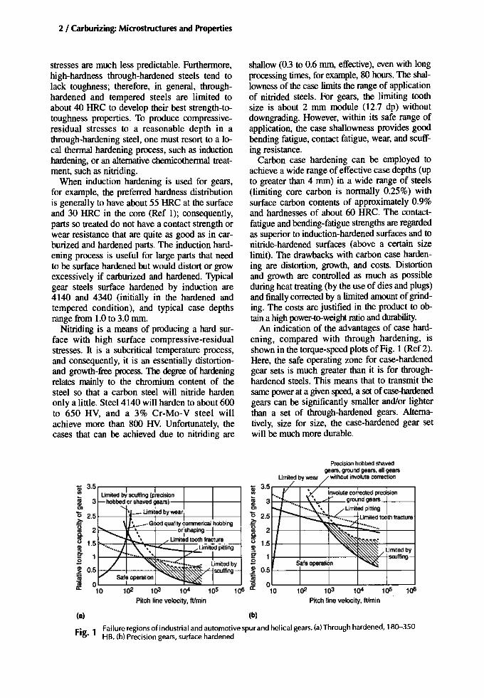
An indication of the advantages of case hardening, compared with through hardening, isshown in the torque-speed plots of Fig. 1 (Ref 2).Here, the safe operating zone for case-hardenedgear sets is much greater than it is for throughhardened steels. This means that to transmit thesame power at a given speed, a set of case-hardenedgears can be significantly smaller and/or lighterthan a set of through-hardened gears. Alternatively, size for size, the case-hardened gear setwill be much more durable.
Urriled byscuffing
lOS l OSPilch line velocity, ftImin
Precision hobbed shavedgears. ground gears. all gears
without involute correction
"0 2.5 1---+----'''''1--=-""'''''~~_t.~'uaco~ 1.5 H----+---+--':>E!s
.~ 0.5 t-- --+- - -+-- - +-- - t-----1Cila; OL..-----'--:---'-:~-""--:---'_:_-~
lOS a: 10
Urn ted byscuffing
toQ)0>
a; 3.5 r----,.----.--~--r---__,(I)
Umited by scuffing (precision3 hobbed or shaved gears)-+---t----l
Urril'ed by wear"0 2.5 t-- --+F---r----..!...---'--+---t-- ---1~ Good quality commerical hobbingTI 2 .9- p....,------1i~-+--or lshaPing
- Urn ted tooth fracture~ 1.5 uffiiiiid Pitting
e- l l--J~::.......:l"""'; :;::--7'f---'--- +---js.~]iQ)
a:
(a) (b)
Fig. 1 Failure regions of industrial and automotive spur and helical gears. (a)Through hardened, 18().-350HB. (b) Precision gears, surface hardened
Variability
Over the past several decades, the steelmakingindustry has moved from basic open-hearth steelmanufacturing to processes such as VIMNAR;consequently, the quality and consistency ofsteels have improved appreciably. Heat-treatmentfurnaces have improved, as have atmosphere andtemperature control systems. Additionally, thegas-metal reactions, carbon diffusion, and otherprocesses that take place during the carburizingand hardening of steels have become much betterunderstood. Add to these factors the introduction of quality systems that favor process andproduct consistency, and, all in all, there hasbeen considerable improvement (a far cry fromthe days of pack carburizing). Having said that,absolute precision is not attained because,among other reasons, exact steel compositionsare impossible to achieve, and atmosphere control during carburizing is, at best, often only ableto produce surface carbon contents of ±O.05%ofthe target value. Therefore, some metallurgicalvariability must be tolerated.
The grade of steel for a given machine component design, the carburized case depth, and thetarget values of surface carbon adopted by amanufacturerlheat treater are based on experience, design procedures, and guidelines providedin national or international standards, and perhaps on adjustments indicated by laboratorytest results. It is difficult to determine the optimum metallurgical condition for a given situation; what is optimum in terms of surface carbonor case depth for a gear tooth fillet is differentfrom what is optimum for a gear tooth flank. Infact, even if the optimum condition is knownfor any given situation (and this can vary fromsituation to situation), the heat treater probablycould not provide it due to the variability described in the previous paragraph and the factthat most heat treaters are happy to get surfacehardnesses within a fairly wide 58 to 62 HRCrange, and effective case depths within a 0.25 mmrange. Further, without considering section size,the previously mentioned composition variability could give batch-to-batch core-strength variations within a 20 ksi band. Hence, the ideal andthe achievable are often different. Gear standardscater to different classes of gears, and these different classes require different degrees of dimensional precision and finish, as well as differentstandards of inspection. It is unlikely, however,that the heat treater will be lax for the lowest
Introduction and Perspectives / 3
grade and fastidious for the precision gear. Inmost cases, the heat-treatment procedures will beto the same standard, and the heat treater willperform in the best way possible every time.
Laboratory Tests
Laboratory tests to determine the effect ofmetallurgical variables, for example, carbides,retained austenite, and core strength, are veryuseful and have contributed appreciably to theunderstanding of the influences of metallurgicalfeatures on material properties. However, thereare problems associated with laboratory testingthat must be recognized and, where possible, allowed for. One problem is that the test specimenand method of loading often bear little relationship to the machine part and service conditionsthey are supposed to represent. Apart from that,test pieces are often small in section so that theproportion of case to core can be high, and themicrostructure can be martensitic throughout thetest section. The effect of these factors on the residual stress distribution and on the contributionof metallurgical features can limit the value ofthe test findings. Another problem is isolatingthe metallurgical feature to be studied; generally,when conducting a test to determine the effect ofa process variation or metallurgical feature onsome property, the researcher attempts to isolatethat test subject. Sometimes this is easy, for example, when determining the effects of tempering or subzero treatment. Other times, it is not soeasy. For example, to determine the influence ofretained austenite on bending-fatigue strength, alarge batch of test pieces are prepared. Half areleft as carburized and hardened with a high retained austenite content at the surface; the otherhalf is refrigerated to transform much of thesurface retained austenite. This is a commonmethod of arriving at two retained austenite levels, but what exactly is being studied? Is it the effect of retained austenite, or is it the effect ofsubzero treatment? It is agreed that there are twoaustenite levels. Is it the difference in austenitelevels that causes a difference of fatigue strength,or is it the effect of the new martensite and its associated short-range stresses induced by refrigeration that are responsible for the difference? Themanufacture of batches of test pieces that areidentical apart from the presence or absence ofnetwork carbides is another example. One can

4 / Carburizing: Microstructuresand Properties
standardize surface carbon content and vary theheat treatment, or one can standardize heat treatment and vary the surface carbon content. Eitherway, there will be differences other than the carbide network. Nevertheless, laboratory testingprovides trends and indicates whether a metallurgical feature will have a small or a large effect onthe property under study.
Design Aspects
Laboratory test pieces are designed and loadedto fail. Machine parts, on the other hand, are designed and loaded not to fail. The basic allowable stresses used by gear designers have beenconservative in order to acknowledge that designprocedures are not precise enough to cater to thevery wide range of gear designs, and that material variability and process variability do exist.These basic allowable stresses are derived fromactual gear tests and areset at a lower value thanthat of failure stress. For example, in Fig. 2, thesurface-hardened test gears failed due to toothpitting at contact stresses of 1400 to 1500 MFa.These tests represent nitrided marine and industrial gears that have, in this instance, a designlimit of about 1000 MFa (Ref 3). Comparablegear tests have been conducted for case- hardened automotive gears and aerospace gears.From these tests, appropriate allowable stress values (for both bending fatigue and contact fa-
tigue) have been derived that are somewhat lessthan the actual failurevalues.The basic allowablesare published in the gear standards (e.g.,ANSIJAGMA 2001 or ISO 6336) (Table la andb). One should consider that for full-scale geartesting, the metallurgy of the tested gears mightbe typical of one heat treater's quality, whichcould rate either high or low against other heattreaters' qualities. This is another reason for setting the design allowables lower.
Designers also incorporate into a design safetyfactors that will account for any adverse effectsof material and manufacturing variability. 'Therefore, there areprobably numerous case-hardened partsperforming satisfactorily in service with surfacemicrostructures that contain adverse metallurgical features. For example, the high-temperaturetransformation products that accompany internaloxidation tend to be frowned upon, yet there arenumerous case-hardened gears in service with unground roots that, therefore, contain degrees ofinternal oxidation. If the test gears from whichthe basic allowable stresses were derived had unground roots and fillets, then internal oxidationwill be accounted for anyway. A metallurgicalfeature might indeed lower the strength of a part(according to laboratory test results), but the applied service stresses must be high enough forthat feature to be significant and cause failure. Ifthe basic allowable stress and the gear designer'ssafety factor together reduce the service stressesto, say, half the failure strength of the part, but
0.005 0.01 0.015 0.02
Ratioof effectivecase depth (500 HV)to relativeradiusof curvature
Fig. 2 The results of full-scale gear tests (failure bytooth pitting) and the typical design stresses used for industrial and marine gears. DNV, Det Norske Veritas.Source: Ref3
Table 1(a) Basic allowablestressnumbersforgears, ISO6336·5 1996
Stresses are shown in MPa, and all hardness values are convened toHV.Designersshouldrefer to the appropriatestandard.(a) Varieswithcore hardness and/orcore strength
700-s5070Q-85065Q-850
500-650500-650450-650
515-620515-620490-655
670-745645-745615-800
375-405360-270225-275
525452-500(a)
315
Induction hardened
ME 1275-1330MQ 1160-1220ML 960-1090
Gas nitrided, through bordened and tempered
ME 1210 435MQ 1000 360ML 785 255
Gas nitrided, nitriding steels
ME 1450 470MQ 1250 420ML 1125 270
CoDl8ctstress BendingstressQuality grade Umit(a. l,MPa limit(a. l,MPa IIardDess, HV
Carburized and hardened
ME 1650MQ 1500ML 1300
• A
A OContact stresslim~DNV
-- .. ---. ---_.._-- 0·······1········D
0 r0D Nilrided gears
D • Failed, full-scale geartestA Not failed, full-scale geartesto Not failed, industrial gears
(4-15yearsservice)D Not failed, marine gears
(1.5-15yearsservice)
1500
2000
~~
:il!! 10000;
i8
500

Introductionand Perspectives / 5
the heat treatment has induced a serious adversemetallurgical feature with a strength reductionpotential of, say, 30%, there still might not be aproblem (Fig. 3). However, if something shouldgo wrong, for example, if a bearing begins to deteriorate or the gear is slightly misaligned, increasing the tooth stress, then failure is morelikely to occur.
It is not suggested here that one should ignorethe metallurgical condition, or that quality control should be relaxed because design, to someextent, accommodates metallurgical variability.On the contrary. It could be that on many occasions the designer's generosity has, in effect,"saved face" for those responsible for the metallurgical quality. If the metallurgical variabilitycould be reduced across the board, and improvedquality and quality consistency could be guaranteed, then perhaps the basic allowable stressescould be increased a little. If nothing else, product reliability would be improved. Designersstrive to improve their design procedures, manufacturers aim to produce levels of accuracy andfinish the designer specifies, and lubrication engineers seek to improve their products. Togetherthese efforts will lead to better power-to-weight
ratios and, hopefully, reduced costs. Therefore,the metallurgists and heat treaters must continueto contribute to the cause.
Currently, it is believed that the limitations ofthe conventional case-hardening steels are fairlywell understood. Any other gains must be madethrough design and process refinements (consistency and accuracy) sufficient to enable revisionof the design allowables.
The future might never provide a casehardening steel that is superior in all respects tothe conventional grades. Even if it did, the costof the steel might limit its use to very specializedapplications. However, it is possible to design asteel that is superior with respect to one property.The newer grades of special-purpose aerospacegear steels for use at high operating speeds andtemperatures exemplify this designing for purpose. Examples of such steel are Pyrowear Alloy53 (Carpenter Technology Corp., Wyomissing,PAl, CBS-lOOOM VIM-VAR (Tirnken LatrobeSteel Co., Latrobe, PAl, CBS-600 (Tirnken Co.,Canton, OH), Vasco X2-M, and LatrobeCFSS-42L, for which the steel compositions andheat-treatment operations depart sufficientlyfrom the conventional. Previously, SAE 9310steel was preferred by the aerospace industry for
Table 1(b) Basic allowablestressnumbersforgears,AGMA 2001-C95
Stresses are shown in MPa.and all hardness values are converted toHV. Designers should refer to the appropriate standard. This table isfor spur and helical gears. (a) Depends on bainite content. (b) Varieswith core hardness and/or strength
30%lossof fatigueIimttdue10an adverse
metallurgical feature
,,,,,,,
Probable maindesignI---+--+-----t rangefor infinitelife
160
140
120
100
~80iii
'"~en60
40
20
Fig. 3 Theoretically a "safe" gear design can accommodate the presence of an adverse metallurgical feature;however, there may be other adverse factors involvedthat also erode the difference between the fracture stressand the allowable stress.
O'----'------'-----'-:------'-:-----L-:------'103 1()4 1()5 1()6 107 1()ll 109
Stresscycles
650-800650-800600-800
Hardness, HV
580minimum690580690580690
42O-44O(b)42Q-44O(b)395-4OO(b)395-4OO(b)280-31O(b)280-31O(b)
520450 or 480(a)
380
Gas nitrided, 2~~ Cr steel
3 13001490
2 1190135010701210
2
Quality Contact ....... 6mit Bendiug stress 6mitgrade (SAC).MPa (SAT),MPa
Carburized and hardened
3 19002 1550I 1240
Induction hardened
2 1310 152 515minimum1345 152 5801172 152 5151210 152 580
Gas nitrided, hardened and tempered, 4140and 4340
3 1210 460 minimum1240 4851125 317-372(b) 4601160 317-372(b) 4851030 234-276(b) 4601070 234-276(b) 485

6 I Carburizing: Microstructures andProperties
gears, but its limitations (questionable hotstrength, for example) inhibited design progress.The high-temperature limitationsof lubricants forhigh-speed, high-temperature gearing is anotherfactor to consider. The new grades of steel aredesigned to maintain their strength at operatingtemperatures and resist scoring and scuffing,
which have a high potential to occur inhigh-speed, high-temperature gearing (Fig. 1).This resistance may, to some extent, make up forthe limitations of the lubrication.
Metallurgy is only one factor in a biggerpicture that includes machine and componentdesign, manufacturing accuracy, machine
180
6/ 0
oj
] 6 je 0
f VJ ~
/ • / // v.'
I I::; f 0
(v
V / /J
; / / Ivo ~/ I01
/ 1 VVeJ
1/ (e)
.""**"",,. (ej
II ,I.· •••;'~roUgh-hardenedsteels
J • 0 Flame-hardened steel
I ~t·· e
• Induction-hardened steelv Gas-nnrided andsan-bath nliridedsteel• Sulphinuz-treated steel..... o Gas-nlirided (80h) steel
/~ (v). (e) Maraging steel
V • Gas-carburized andhardened6Gas-carburized. hardened andtempered
2530
2431
2327
2220
2106
'"1985
Q. 8::Egj
1857x
l!! J:lii enGl
~~'" 1718 Gll!! :::JC.
~E8 u,
1569
1404
1216
993
702
00
26
24
22
20
18
16
14
12
10
8
6
4
2
20 40 60 80 100 120 140 160
367
352.5
337.5
321.8
305.5
288~
269 i-~
249 ~~8
227.6
203.6
176
144
102
Steel
Through hardened (various)Flamehardened (PCS)Induction hardened (4340)Gas nitrided and salt-bath nitridedSulphinuz treatedGas nitrided (SOh) (3%Cr-Mo)Maraging (x)Gas carburized, hardened, and tempered (Ni-Cr)Gas carburized and hardened (Ni-Cr)
Corestrength. tsi
Effective casedepth, IDDl (io.)
3.75 (0.15)0.14 (0.005)0.17 (0.007)0.35 (0.015)0.14 (0.005)
1-1.5 (0_()4.4).06)1.5(0_06)
Fi~. 4 Effect of core strength and case depth on the rolling-contact fatigue limit of gear steels. Tests invoTvedtwo 4 in. disks driven by a 2 in. roller. Testpiece may have been either one of the disks or the roller.Relative radius of curvature, 2/3. SH units = Ib/in. of face width divided by the relative radius of curvature.

Introduction and Perspectives / 7
assembly, lubrication, application, machine useor abuse, and maintenance (or lack of it). Thisbook considers some of the current knowledgeregarding the metallurgy of case-hardened steelparts and what effects or trends the various metallurgical features have on the properties of suchparts. However, it focuses on conventionalcase-hardening steels and processing and, therefore, might not be as helpful to designers and users of new alloy grades.
Case-Depth Specifications
At the dedendum-pitch line area of a geartooth, there is a smaller radius of curvature thanat locations above the pitch line. Consequently,the contact band there tends to be narrower thanat the addendum so that for a given load, the contact stresses will be higher. For that reason, the
chosen case depth must be adequate to resist thestress at the dedendum-pitch line area.
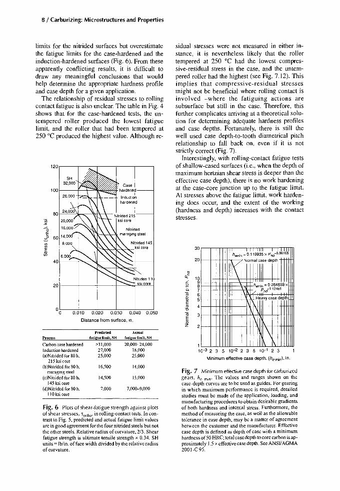
The contact stress increases with transmittedload so, strictly speaking, the case depth shouldbe determined by the load. Using the shear-fatiguestrength (ultimate tensile strength x 0.34) of thematerial as opposed to shear stresses due to loading appears to give some conflicting results;therefore, it is not clear on which shear stressesthe case depth requirement should be based. Forexample, if the 45° shear stresses ('tyz) are considered in conjunction with the test results shownin Fig. 4, it is found that, for the 80 hour-nitridedsurfaces, the predicted fatigue limit is about halfof the value determined by testing. On the otherhand, the fatigue limits for the carburized, hardened, and tempered surfaces (100 to 200 "C) andfor induction-hardened surfaces are better predicted (Fig. 5). The orthogonal shear stresses('tortho)' however, predict fairly well the fatigue
120 r--....-----,r_--.------r---r----,.--~-__r_--r_-_r_-____,-_____,
Nltrkled steels(seealsoFig. 6)
20~-_+--I-- 0215 ksi core• MaragingA 145 ksi core.. 110 ksi core
80
~
1- 60UlUl
~40
100
o~___:~:::--_::_::=___:::-===__-:-:!:_:_:___:_~,.___=-:':=__=_=__:=_=_:__::_::=___:::_:_::=___::_!7:___:__:'.o 0.010 0.020 0.030 0.040 0.050 0.060 0.070 0.080 0.090 0.100 0.110 0.120
Distancefrom surface,in.
Process Predicted roUp_limit, SH Actual roUp_limit, SH
Carboncase hardened,untemperedTemperedat 100°CTemperedat 150°CTemperedat 200 °CTemperedat 250°CInductionhardenedNilridedsteels
24,000 18,00024,000 22,00024,000 23,00022,000 25,00020,000 26,80018,000 -18,000
Predictionequalsaboutone half of actual
Fig. 5 Plots of shear-fatigue strength (from hardness) against plots of shear stresses, "tyz, in rolling-contacttests. Predicted and actual fatigue limit values are in close agreement for carburized steels but not for the fournitrided steels. Relative radius ofcurvature, 2/3. SH units = lb/in. of face width divided by the relative radius ofcucvature.
8 / Carburizing: Microstructures and Properties
I IIIIII1I I_JaWslhemin=0.119935xPnd .
\ NoriiWi
e drlhemin = 0.264693 x
Pnd-1.124a1
Heavycase depthi
1\
'\1\ ~
3
2
"t>
QC 1098765
4
Cl.
~WE
'"'6tiiEaz
30
Fig. 7 Minimum effective case depth for carburizedgears, he min' The values and ranges shown on thecase-depth curves arc to be used as guides. For gearingin which maximum performance is required, detailedstudies must be made of the application, loading, andmanufacturing procedures to obtain desirable gradientsof both hardness and internal stress. Furthermore, themethod of measuring the case, as well as the allowabletolerance in case depth, may be a matter of agreementbetween the customer and the manufacturer. Effectivecase depth is defined as depth of case with a minimumhardness of50 HRC; total case depth to core carbon is approximately 1.5 x effective case depth. Sec ANSIIAGMA2001-C 95.
20
110-3 2 3 5 10-2 2 3 5 10- 1 2 3
Minimum effectivecase depth, (he min), in.
sidual stresses were not measured in either instance, it is nevertheless likely that the rollertempered at 250 °C had the lowest compressive-residual stress in the case, and the untempered roller had the highest (see Fig. 7.12). Thisimplies that compressive-residual stressesmight not be beneficial where rolling contact isinvolved-where the fatiguing actions aresubsurface but still in the case. Therefore, thisfurther complicates arriving at a theoretical solution for determining adequate hardness profilesand case depths. Fortunately, there is still thewell used case depth-to-tooth diametrical pitchrelationship to fall back on, even if it is notstrictly correct (Fig. 7).
Interestingly, with rolling-contact fatigue testsof shallow-cased surfaces (i.e., when the depth ofmaximum hertzian shear stress is deeper than theeffective case depth), there is no work hardeningat the case-core junction up to the fatigue limit.At stresses above the fatigue limit, work hardening does occur, and the extent of the working(hardness and depth) increases with the contactstresses.
100 f---f--+-'"
Predicted Actual
Process fatigue limit, S8 fatigue limit, SH
Carbon case hardened >31,000 20,000-24,000Induction hardened 27,000 18,000(a)Nitrided for 80 h, 25,000 25,000
215 ksi core(b)Nitrided for 80 h, 16,500 14,000
maraging steel(c)Nitrided for 80 h, 14,500 15,000
145 ksi core(d)Nitrided for 80 h, 7,000 7,000-9,000
110 ksi core
201-------i1--------i---+--=.....-'=-"""-'"--l
Fig. 6 Plots of shear-fatigue strength against plotsof shear stresses, 'artha' in rolling-contact tests. In contrastto Fig. 5, predicted and actual fatigue limit valuesare in good agreement for the fournitrided steels but notthe other steels. Relative radius ofcurvature, 2/3. Shearfatigue strength is ultimate tensile strength x 0.34. SHunits = lb/in. offace width divided by the relative radiusofcurvature.
0.010 0.020 0.030 0.040 0.050
Distance from surface, in.
120,..---.,---.,-----r----r------,
limits for the nitrided surfaces but overestimatethe fatigue limits for the case-hardened and theinduction-hardened surfaces (Fig. 6). From theseapparently conflicting results, it is difficult todraw any meaningful conclusions that wouldhelp determine the appropriate hardness profileand case depth for a given application.
The relationship of residual stresses to rollingcontact fatigue is also unclear. The table in Fig. 4shows that for the case-hardened tests, the untempered roller produced the lowest fatiguelimit, and the roller that had been tempered at250 °C produced the highest value. Although re-

Eutectoid Carbon Content
The requirements and information in any standard are, in general, readily understandable andrealistic, as they should be. Unfortunately, thereare exceptions. For example, the surface carbonrequirement for carburized gears as set out inISO 6336-5 1996 is "Eutectoid carbon %+0.20%, -D. 1%." The standard does not justifythe use of the term eutectoid. It does not providea list of case-hardening steels along with a representative value of eutectoid carbon for each steel,nor does it provide an empirical formula for determining the eutectoid carbon. It is, therefore,unhelpful and unworkable as it stands. However,it is understood that the standard is to be revisedto correct the problem.
The term eutectoid carbon content refers tothe carbon content that produces only a pearliticmatrix microstructure as a result of an extremelyslow cool through the AC3 or ACcm to ACl temperature range. A steel with less than theeutectoid carbon content (hypoeutectoid) contains pearlite with some ferrite, whereas a steelwith more carbon than the eutectoid carbon content (hypereutectoid) contains some carbidealong with pearlite, again due to very slow cooling. Each steel grade has its own eutectoid carbon content, and considering the whole range ofconventional case-hardening steels, the eutectoidcarbon contents could easily vary between 0.45and 0.8%. In case-hardening practice, the cooling rates employed, even slow cooling from carburizing, are much faster than the cooling ratesresearchers would use to determine the eutectoidcarbon for an equilibrium diagram. Rapid cooling, typical of commercial quenching, can suppress the formation of ferrite in lean-alloy steelswithin about 0.2% C less than the eutectoid andsuppress the carbide formation in that steel whenthe carbon is up to about 0.2% above theeutectoid. Suppression of ferrite or of carbidemeans that the carbon will be in solution in the
Introduction and Perspectives / 9
martensite and in any retained austenite. Considerthen: is a eutectoid carbon martensite the best toprovide all the properties sought for a given application? Or is it the best carbon content for holdingthe retained austenite to a low value or for developing a better case toughness? Would a case-hardened 9310 steel gear with a surface carbon contentof 0.55% be regarded as fit for service eventhough it might satisfy the case carbon requirements oflSO 6336-5 (1996)?
To establish where the eutectoid carbon content figures in deliberation regarding propertyoptimization for case-hardened parts (and indeedit may have a place), there is little alternative butto establish eutectoid carbon data for each steel.For this, it may not be necessary to go throughthe complex procedure of determining accurateequilibrium diagrams. Instead, a set procedurecould be devised in which, for example, a 30 mmbar is carburized to, say, greater than 1% surfacecarbon content and cooled, or heat treated to precipitate the excess carbon as carbides. The bar isthen cut into two: one half is used to determinethe carbon gradient and the other is used as ametallographic sample to determine the depth ofcarbide penetration. The two sets of data are thenbrought together to give a value of carbon atwhich, under the set conditions, carbides just appear. This could then be referred to as the "apparent eutectoid." Only with such informationcould the merits of the case carbon requirementof the ISO 6336 standard be assessed.
REFERENCES
1. G. Parrish, D.w. Ingham, and J.M. Chaney, TheSubmerged Induction Hardening of Gears, Parts 1and 2, HeatTreat. Met., Vol 25 (No.1) 1998, P 1--8,and Vol 25 (No.2), p 43-50
2. M. Jacobson, Gear Design: Lessons from Failures,Automot. Des.Eng., Aug 1969
3. I.T. Young, The LoadCarrying Capacity ofNitridedGears, BGMA, London, 1982

Chapter 1
Internal Oxidation
The presence of internal oxidation at thesurfaces of parts that are case hardened bypack or gas carburizing has been known of forfifty years or more. The high-temperaturetransformation products (HTTP), which canform as a direct consequence of internal oxidation, have subsequently been found to haveadverse influences on certain strength properties of affected parts; therefore, these products are of some concern to metallurgists andengineers.
The use of oxygen-free gas-carburizing atmospheres or vacuum-carburizing processes isknown to eliminate the oxidation process, andnitrogen-base atmospheres are said to reduce it.However, conventional gas carburizing using theendothermic carrier gas is still the most popularmethod of case hardening, and its use will continue for many years. Thus, the problems relatedto internal oxidation will persist as long as theconventional process lives. Therefore, it isimportant to understand how internal oxidationcomes about, what its likely effects are on material properties, and what should be done about it,bearing in mind that it has generally been tolerated in the past.
Factors Promoting Internal Oxidation
Endothermic Atmosphere. Gas carburizing isnormally carried out at a temperature within therange of 900 to 950°C using an endothermiccarrier gas generated by the controlled combustion of another gas (such as natural gas, liquidpropane gas, or towns gas) with air in the presence of a catalyst at a high temperature. Preparedfrom natural gas (methane), the endothermic at-
mosphere has a typical composition of 40% H,20% CO, 0.46% CH4, 0.27% CO2, and 0.77%H20 (vapor; dew point, 4°C), with a balance ofnitrogen. Such a mixture will have a carbon potential for iron of approximately 0.4% at 925°C;therefore, in order to effect the carburization ofsteel components to the required surface carbonlevels, endothermic gas must be enriched bycontrolled additions of a suitable hydrocarbon,such as propane or methane.
The balance of the component gases ensuresthat the endothermic atmosphere is reducing toiron, the parent metal of the steel, noting that thesteel will be in the austenitic state at the temperature for carburizing. However, for those alloyingelements in solid solution in the steel that have agreater affinity for oxygen than iron does, the atmosphere is potentially oxidizing.
Elements That Oxidize. Water vapor andcarbon dioxide are the offending componentgases in the endothermic atmosphere that provide the oxygen for the internal oxidation processes. The oxidation potentials of the main elements used for alloying can be derived from theratios of partial pressures of the oxidizing and reducing constituents in the atmosphere, that is,pH20 to pH2 and pC02 to pCO. The results ofsuch calculations, as presented by Kozlovskiiet al. in Ref 1 for a temperature of 930°C, areshown graphically in Fig. 1.1. This diagramshows that of the elements studied, titanium, silicon, manganese, and chromium are likely tooxidize, whereas iron, tungsten, molybdenum,nickel, and copper will not oxidize. This, ofcourse, refers to elements that are not combined(i.e., those in solid solution). 1\\'0 possibly important omissions from this diagram are aluminum and vanadium, both of which are common
Carburizing: Microstructures and Properties Copyright © 1999 ASM International® Geoffrey Parrish, p 11-36 All rights reserved.DOI: 10.1361/cmap1999p011 www.asminternational.org

12 / Carburizing: Microstructures and Properties
additions to steels. According to Fig. 1.2 (Ref2), these elements will oxidize in an endothermic atmosphere; thermodynamically, aluminum appears to be slightly more ready to oxidize than does titanium, whereas vanadiumwill have an oxidation potential somewherebetween those of silicon and manganese. It
can be seen that elements favoring internaloxidation are generally necessary to the steelto impart characteristics such as hardenability, toughness, and grain refinement; butironically, in some cases, their function is toassist in the deoxidization process duringsteel melting and casting operations.
14
12Ti
Calculations basedon the equations:
10 Oxidation of oMe + H20 :? MeO+H2'"c:: metals0 8.... fd Me + CO2 :?~ MeO+CO
6.e
4~s 28-c:: 00~os
-2~0 Reduction of
-4 metaloxides
Cu-8'-- -J
Fig. 1.1 Oxidation potential of alloying elements and iron insteel heated in endothermic gas with an average composition of40% H 2, 20% CO, 1.5% CH 4 , 0.5% CO 2, 0.28% H 20 (Dewpoint,10 0C), and 37.72% N2• Source: Ref 1
106
1010r----~---------__,
106
Pb/PbO
104
1()2 1()2'"t
~WIWO0
'" FelFe304t
10-2
10-4
1~
10-8
10-10200
BOO 1000 1400600 BOO 1000 1400 600
Temperature, °C Temperature, °C
(8) (b)
Fig. 1.2 Critical requirements for the oxidation of selected metals with indicated temperatures in atmospheres containing (a) water vapor and hydrogen and (b) carbon dioxide and carbon monoxide. Source: Ref 2
Internal Oxication / 13
The Internal Oxidation Process
lA .LUnto
\'Il.L
.M
oo 2 4 6 8 10Carburizing time, h
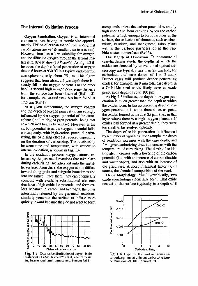
FiK. 1.4 Depth of the oxidized zones vs.caiburizing time at different carburizing temperatures for SAE 1015. Source: Ref 6
compounds unless the carbon potential is undulyhigh enough to form carbides. When the carbonpotential is high enough to form carbides at thesurface, the oxidation of elements, such as chromium, titanium, and manganese, takes placewithin the carbide particles or at the carbide-austenite interfaces (Ref 5).
The Depth of Oxidation. In commercialcase-hardening steels, the depths at which theoxides are detected by conventional optical microscopy are typically less than 25 um (i.e., forcarburized total case depths of 1 to 2 mm).Deeper cases will produce deeper penetratingoxides; for example, an 8 mm total case depth ina Cr-Ni-Mo steel would likely have an oxidepenetration depth of75 to 100 urn.
As Fig. 1.3 indicates, the depth of oxygen penetration is much greater than the depth to whichthe oxides form. In this instance, the depth of oxygen penetration is about three times as great;the oxides formed in the first 25 urn, (i.e., in thatlayer where there is a high oxygen plateau). Ifoxides had formed at a greater depth, they weretoo small to be resolved optically.
The depth of oxide penetration is influencedby a number of variables. For example, the depthof oxidation increases with the case depth, andfor a given carburizing time, it increases with thetemperature of carburizing. The depth of oxidation also increases with a lowering of the carbonpotential (i.e., with an increase of carbon dioxideand water vapor), and also with an increase ofthe grain size. A most influential factor is, ofcourse, the chemical composition of the steel.
Oxide Morphology. Metallographically, twooxide morphologies generally form. That oxidenearest to the surface (typically to a depth of 8
./~O°C
/V
V~O°C/ l..-a-'
/'/'
0.012
0.008
EE 0.Q16Co
I'6s:is.~
0.020
0.004
Jg§ 5Ql
~ 4os~ 3
~2o'6 1
§O~ 0 10 20 30 40 50 60 70 80 90 100c( Distance fromsurface, 11m
Fig. 1.3 Qualitative distribution of oxygen in thesurface of a Cr-Mn-Ti steel (25KhGT) after carburizing in an endothermic atmosphere. Source: Ref 3
Oxygen Penetration. Oxygen is an interstitialelement in iron, having an atomic size approximately 33% smaller than that of iron (noting thatcarbon atoms are -34% smaller than iron atoms).However, iron has a low solubility for oxygen,and the diffusion oxygen through the ferrous matrix is relatively slow (1<r9 cm2/s). As Fig. 1.3 illustrates, the depth of total penetration of oxygendue to 6 hours at 930°C in a typical endothermicatmosphere is only about 75 urn. This figuresuggests that from about a 5 urn depth there is asteady fall in the oxygen content. On the otherhand, a second high oxygen peak some distancefrom the surface has been observed (Ref 4, 5);for example, the second peak has been found at17.5 urn (Ref 4).
At a given temperature, the oxygen content~d the depth of oxygen penetration are stronglyinfluenced by the oxygen potential of the atmosphere (the limiting oxygen potential being thatat which iron begins to oxidize). However, as thecarbon potential rises, the oxygen potential falls;consequently, with high-carbon potential carburizing, the oxidizing effect is reduced dependingon the duration of carburizing. The relationshipbetween time and temperature, with respect tointernal oxidation, is shown in Fig. 1.4.
In the oxidation process, oxygen atoms, released by the gas-metal reactions that take placeduring carburizing, are adsorbed onto the metallic surface. From there, the oxygen atoms diffuseinward along grain and subgrain boundaries andinto the lattice. Once there, they can chemicallycombine with available substitutional elementsthat have a high oxidation potential and form oxides. Meanwhile, carbon and hydrogen, the otherinterstitials released by the gas-metal reactions,similarly penetrate the surface to diffuse morequickly inward because they do not react to form

14 / Carburizing: Microstructures and Properties
urn) appears as globular particles of about 0.5urn in diameter. This oxide resides mainly in thegrain and subgrain boundaries and, to a lesserextent, within the grains themselves. Sometimesit occurs along the surface. Within this surfacezone, the grains are likely to be subdivided intovolumes of 0.5 to 1 urn across, although diameters of 2 to 4 um have been quoted (Ref 3). Thesecond type of oxide resides at typical depths of5 to 25 um and mainly occupies the prior austenite grain boundaries where it appears as a continuous "dark phase" (Ref 7), dark enough to resemble a void.
One can envisage that, as the oxygen gradientbegins to develop during the carburizing process,the globular precipitates will start to form at theboundaries nearest to the surface and continue togrow as adequate quantities of reactants arebrought together. However, Van Thyne andKrauss (Ref 8) have shown that the formation ofthe globular boundary oxides takes place by adiscontinuous, lamellar growth process ; that is,rods of the oxide form, each separated from thenext by a band of alloy-depleted austenite. Theserods tend to grow in the direction of the oxygengradient. The oxides appear as rows of sphereswhen, in reality, the cross sections of rods are being viewed. At greater depths within the oxidized layer, the oxides appear to be continuousand at the prior austenite grain boundaries (Fig .1.5).
The grain size at the surface of the steel isthought to influence oxide formation in that asthe grain size decreases, the probability of forming oxides within the grains increases (Ref 3).However, it is suggested that the effect of temperature on penetration depth, as illustrated inFig. lA, might also be affected by grain size(Fig. 1.6). One can imagine for a given oxidizingpotential of the atmosphere that the more grainboundaries there are at which to distribute theavailable oxygen, the less the penetration will be.
Thus, steel composition and grain size are involved in the internal oxidation process. Butwhat about carburizing conditions? What is certain is that when carburizing in an endothermicatmosphere containing 20% CO and 0.2 to 1%CO2, the format ion of internal oxidation is unavoidable. Dawes and Cooksey (Ref 10) estimate that 0.2% would be the maximum value ofCO2 that could be tolerated to prevent the internal oxidation of a 1% Cr steel, and that 0.01%CO2 would be the limit for a 1% Mn steel.Mitchell , Cooksey, and Dawes illustrate how internal oxidation increases with manganese content and add that the severity of attack is relatedto the total case depth (Ref 11). Chatterjee-Fischeragrees with this, stating that samples havingcomparable case depths, arrived at by carburizing at two entirely different temperatures, wouldhave the same depth of internal oxidation, eventhough the morphology of the oxides might differ somewhat (Ref 6). For a given temperature,
r: _.•
. ....
. ..'
• L.
: .... '-! . - : .
. .. ,Fig. 1.5 Internal oxid ation of a Ni-Cr steel carburized in a laboratory furnace, showing bothgrain boundary oxides and oxide precipitates within grains. SSOx

Postcarburizing Mechanical Treabnents / 15
the increase of depth of internal oxidation is proportional to the square root of the carburizingtime. Edenhofer found that when carburizing a16MnCr5 steel with the carbon potential and carburizing duration each held essentially constant,doubling the carbon monoxide content from 20to 40% doubles the depth to which internal oxidation penetrates (Ref 12).
The Oxidation of Two-Component Alloys. Whereas Fig. 1.1 indicates which elements of a steelare likely to oxidize during carburizing , it givesno clues regarding how much of anyone element is needed for the oxidation reaction totake place. Employing pure two-component alloys, for example Fe-Si, Fe-Mn, and Fe-Cr,Chatterjee-Fischer confirms that those alloyscontaining elements with a propensity to oxidizedo indeed oxidize, provided that a sufficientamount of that element is present (Ref 6). Figure1.7 summarizes her results and provides information regarding atomic number and size. It canbe noted that the elements with the larger atomicsizes, or smaller atomic number, need only bepresent in amounts of less than 0.1 vol% to promote oxidation, whereas significantly more isneeded of those elements whose atoms are of asimilar size to that of iron. Alloy contents inamounts greater than those threshold values
shown in Fig. 1.7 will lead to more of the oxidebeing produced. An increase in the silicon content, everything else being equal, will influencethe depth of oxide penetration in a negative wayand will increase the amount of grain-boundaryoxide formed. In this respect, it was shown thatincreasing the silicon content of the iron-siliconalloy from 0 to 1.83% produced isolated fineprecipitates to a depth of -20 um when the silicon was equal to 0.09%; dense globular andgrain-boundary oxides were produced to adepth of only -10 urn when silicon was equal to1.83% (Ref 6). Between these two amounts ofsilicon, the quantity of oxide increased withsilicon content, but the depth at which it formeddecreased.
The Oxidation of MulticomponentAlloys. Withmulticomponent alloys (and commercial gradesof carburizing steels), the situation is rather morecomplicated. In such alloys the silicon content tocause internal oxidation is about half that for astraight iron-silicon alloy (i.e., 0.05%), which iswell below the 0.2 to 0.3% silicon content typical of case-hardening steels. This suggests thatwhile these typical silicon contents are used, internal oxidation during conventional gas carburizing will be impossible to prevent. It doesseem, however, that by limiting the manganese
1000800 900Temperature, oC
"1\\\
1\\\
o700
25
200
175
50
~ 150
~.~ 1258-rn6 100
J75
850°C
930 °C
iooo -c
1000800 900
Temperature. °C
//
/0/
V/
4
3700
5
6
9
10
r" n " fl;''j780 °C
Fig. 1.6 Influence of carburizing temperature on the depth of oxide penetration and penetration frequency per millimeter of grain boundary oxidation for steel 17NiCrMo14. Adapted from Ref 9
11
12

16 / Carburizing: Microstructures and Properties
Okasaki, in steels with up to 0.1% titanium, theoxygen, carbon, nitrogen, and sulfur, which inhibit grain growth, combine with titanium to freethe grain boundaries (0.1% titanium having themaximum effect). More titanium is needed torepin them (Ref 14). Therefore, a titaniumcontent in excess of 0.1% would be expected tosupport the internal oxidation reaction. Vanadium is not normally added to case-hardeninggrades of steel for the purpose of, for instance,hardenability or strength, for which something inexcess of 0.1% would be expected. For grain refinement, the amount could be much less thanthat, but whether or not it would be below thethreshold for oxidation is not known.
The Oxidation of Commercial Case-HardeningAlloys. With commercial grades of steel, the observations regarding internal oxidation are attimes confusing, which is not too surprisingwhen one considers that different researchershave employed different steel compositions andcarburizing conditions.
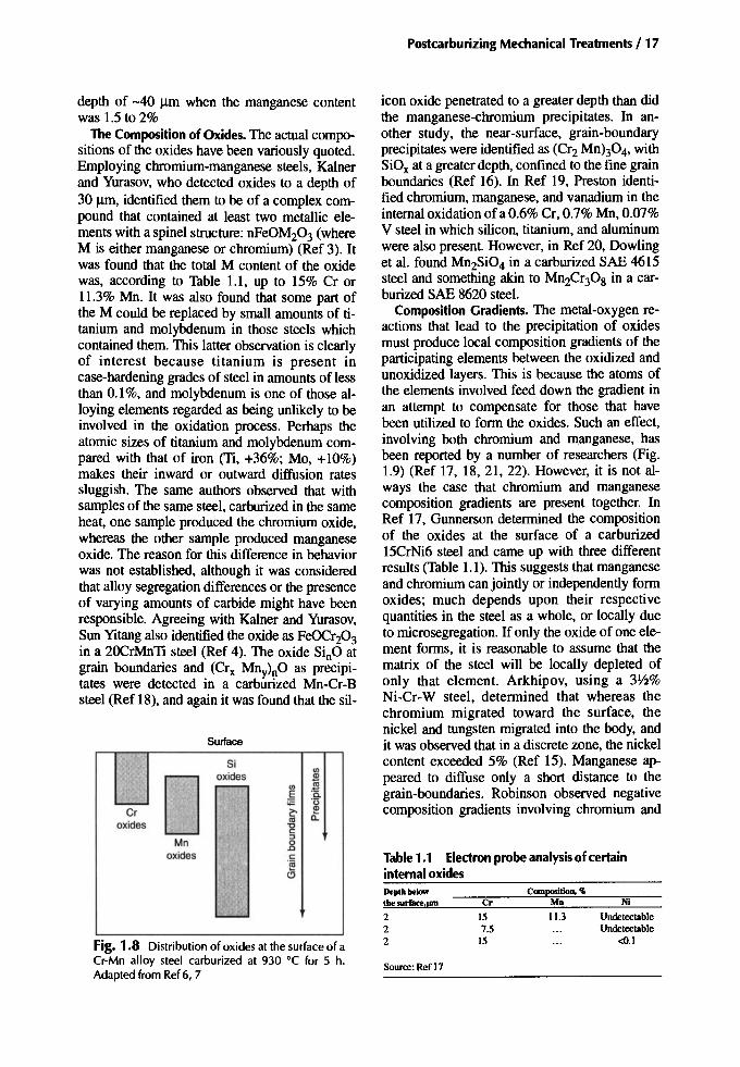
Arkhipov, employing a 18Kh2N4VA steel,found that the silicon and manganese did not oxidize, whereas the chromium did (Ref 15). Thechromium content in this case was 1.65%, thesilicon was 0.28%, and the manganese only0.4%; with another nickel-chromium steel wherethe chromium content was 0.8%, however, theinternal oxidation was less extensive. In yet another study by Arkhipov, this time using aCr-Mn-Ti steel, the larger oxides observed in thesurface (up to 6-8 urn) contained manganese,chromium, and silicon; at greater depths, however, only the oxides of silicon persisted (Ref 7).Essentially the same observations were made byMurai et al. (Ref 16) and Chatterjee-Fischer (Ref6). Figure 1.8 shows a typical distribution of oxides.
This reflects on the fact that the compositionof an oxide phase at any depth from the surfaceis primarily governed by its energy of formation,and the higher this energy is, the deeper the zoneis in which that particular oxide will form.Again, for energy reasons, some oxides tend toform at the grain boundaries while others tend toform at sites within the grains, grain size perhapshaving an influence.
With regard to the quantity of an oxidizable element, Mitchell et al. showed in Ref 11 that withC-Mn-B alloys carburized at 925 EC for 48hours, internal oxidation was light to a depth of-20 urn when the manganese content was 1 to1.5%. Internal oxidation was heavy and to a
101
-1o1I6
-367
14
-58-34-36-33
AtomicsizereJatiwto Iroo, ...
Cr,!\\\Mn
\\ Two component
/ alloys
\ Multicomponent
.) V alliys
15i
vy, ......0 .....
5i Ti AI
Interstitial elementsHydrogen 1Carbon 6Nitrogen 7Oxygen 8
Solid-solution elementsMolybdenum 42Copper 29Nickel 28
Iron 26Manganese 25Chromium 24Vanadium 23Titanium 22Silicon 14Aluminum 13
0.5
0.4
0.3
0.2
O.
and chromium to less than 1% in total, the depthof oxide penetration will be essentially that dueto the silicon content.
The other elements with atomic numbers lessthan that of iron should be considered. Aluminum, for deoxidization and grain size control, isusually present in soluble form in amounts of approximately 0.01 to 0.06%. Though hardlyenough to cause oxidation in an iron-aluminumpure alloy, this could well be enough to do so ina commercial grade, according to the behavior ofsilicon. To be effective as a grain refiner, titanium must be in excess of 0.1%. According to
o-1Q2 -1Q4 -106 -10B -1010 -1012
pC02"PCO
Source: Ref 13
1.3
1.2
1.1
1.0
0.9
~ 0.8
E 0.7Gl
~ 0.6ill
Fig. 1.7 The limiting amount of added element (ofatomic number less than that of iron) to promote internaloxidation. See also Fig. 1.2(bl. Adapted from Ref6
Element Atomicnumber
Postcarburizing Mechanical Treatments /17
Surface
Nt
UndetectableUndetectable
<0.1
Mn
11.3
COII1positioO, "Cr
157.5
15
222
Source: Ref 17
Table1.1 Electronprobe analysisof certaininternal oxides
icon oxide penetrated to a greater depth than didthe manganese-chromium precipitates. In another study, the near-surface, grain-boundaryprecipitates were identified as (Crz Mnh04, withSiOx at a greater depth, confined to the fine grainboundaries (Ref 16). In Ref 19, Preston identified chromium, manganese, and vanadium in theinternal oxidation of a 0.6% Cr, 0.7% Mn, 0.07%V steel in which silicon, titanium, and aluminumwere also present. However, in Ref 20, Dowlinget al. found MnzSi04 in a carburized SAE 4615steel and something akin to MnZCr30g in a carburized SAE 8620 steel.
Composition Gradients. The metal-oxygen reactions that lead to the precipitation of oxidesmust produce local composition gradients of theparticipating elements between the oxidized andunoxidized layers. This is because the atoms ofthe elements involved feed down the gradient inan attempt to compensate for those that havebeen utilized to form the oxides. Such an effect,involving both chromium and manganese, hasbeen reported by a number of researchers (Fig.1.9) (Ref 17, 18, 21, 22). However, it is not always the case that chromium and manganesecomposition gradients are present together. InRef 17, Gunnerson determined the compositionof the oxides at the surface of a carburized15CrNi6 steel and came up with three differentresults (Table 1.1). This suggests that manganeseand chromium can jointly or independently formoxides; much depends upon their respectivequantities in the steel as a whole, or locally dueto microsegregation. Ifonly the oxide of one element forms, it is reasonable to assume that thematrix of the steel will be locally depleted ofonly that element. Arkhipov, using a 3Y2%Ni-Cr-W steel, determined that whereas thechromium migrated toward the surface, thenickel and tungsten migrated into the body, andit was observed that in a discrete zone, the nickelcontent exceeded 5% (Ref 15). Manganese appeared to diffuse only a short distance to thegrain-boundaries. Robinson observed negativecomposition gradients involving chromium and
Sioxides
<Il
DCIl
~ <Il §E "a
'-- s '0Cr z- l!?
oxides '" a."0c
Mn:>.8
oxides c.~
o
L..--
.Fig. 1.8 Distribution of oxides at the surface of aCr-Mn alloy steel carburized at 930°C for 5 h.Adapted from Ref6, 7
depth of -40 urn when the manganese contentwas 1.5 to 2%
The Composition of Oxides. The actual compositions of the oxides have been variously quoted.Employing chromium-manganese steels, KaInerand Yurasov, who detected oxides to a depth of30 urn, identified them to be of a complex compound that contained at least two metallic elements with a spinel structure: nFeOMZ03 (whereM is either manganese or chromium) (Ref 3). Itwas found that the total M content of the oxidewas, according to Table 1.1, up to 15% Cr or11.3% Mn. It was also found that some part ofthe M could be replaced by small amounts of titanium and molybdenum in those steels whichcontained them. This latter observation is clearlyof interest because titanium is present incase-hardening grades of steel in amounts of lessthan 0.1%, and molybdenum is one of those alloying elements regarded as being unlikely to beinvolved in the oxidation process. Perhaps theatomic sizes of titanium and molybdenum compared with that of iron (Ti, +36%; Mo, +10%)makes their inward or outward diffusion ratessluggish. The same authors observed that withsamples of the same steel, carburized in the sameheat, one sample produced the chromium oxide,whereas the other sample produced manganeseoxide. The reason for this difference in behaviorwas not established, although it was consideredthat alloy segregation differences or the presenceof varying amounts of carbide might have beenresponsible. Agreeing with KaIner and Yurasov,~un Yitang also identified the oxide as FeDerZ0310 a 20CrMnTi steel (Ref 4). The oxide Si Oatgrain boundaries and (Crx Mny)nO as pC:Cipitates were detected in a carburized Mn-Cr-Bsteel (Ref 18), and again it was found that the sil-

18 / Carburizing: Microstructuresand Properties
Nl
0.550.57
Mo
0.180.14
Compositloo, ..Cr
0.790.52
Position
SurfaceSubsurface
Source:Ref23
molybdenum at the surface of an SAE 8620 steel(Table 1.2) (Ref 23), whereas Colombo et al.found that there were no diffusion gradients associated with the internal oxidation in a carburized SAE 94B17 steel (Ref 24).
It is understood that much of an element migrating to the surface is utilized in forming theoxide, and that the matrix material in the vicinityof the oxide remains, if not completely depletedof that element, substantially below the averagefor the steel in question.
Apart from what happens to the alloying elements of a steel during the oxidation process, itmay be found that the carbon content is also affected. In Ref 1, Kozlovskii et al. related that asample of a carburized 25KhGT steel exhibited alow carbon content in the layer of internal oxidation (Fig. UOa). Other samples of different steelcompositions used in the same investigation didnot show the same decarburization effect, whichmakes it tempting to believe that this was a caseof normal decarburization. However, using anSAE 94B 17 steel, Colombo et al. determined thecarbon content within the layer of internal oxidation (i.e., within the outermost 20 urn) to be0.53% (Fig. 1.10b) (Ref 24). Shcherbedinskiiand Shumakov also suggested that there was areduced carbon content in the oxidized layer(Fig. 1.11), but only where the oxides haveformed (Ref 5). These researchers consideredthat internal oxidation took place within the carbides, or at the carbide-austenite interfaces,which implies that a high carbon potential is anecessary requirement of the oxidation process.Other researchers have shown that a low carbonpotential (high-carbon dioxide atmosphere) mostfavors internal oxidation. It also favorsdecarburization (see Chapter 2).
Table 1.2 Analysis of the surfacematerial in SAE8620steelcarburizedinendothermicgaswithnaturalgasadditions
20 40 60 80 100Depthbelow surface, 11m
20 30 40 50 60 70 80Depthbelow surface, 11m
20 40 60 80 100 120Depthbelow surface, 11m
I,(CrxMnylnO
r-----H I(SinOlnO
Nominal~r, Mn
- -- --- - - -- - -- -7 -7c,.. - ---
CrjV V
j Mn
1/ // I
1/ 1//
Cr
0-" 0.- 0 ••01. ••• ------ o,0" •.V· ~n
,.0.
/1If
0 N~0
~~ 1.48% Ni
o~ 0 0
", • Mn 0.86% Cr• •• ,,'I."':'~X
•.. s, 10- \ 0.75% Mn. ":~ " Cr I• :f'."" "Mn% -
6!l,' • Cr%.,"' o Ni% -': I.
(8)
1.2
0.2
oo 10
(b)
oo
0.2
oo
(c)
0.2
1.0
t!.E 1.0S!l5 0.8o
~<0.6
0.4
1.6
t!.E 1.0S!l5 0.8o
~4( 0.6
0.4
1.2
1.4
'it 0.8Es8 0.6
~4( 0.4
Fig. 1.9 Composition gradients associated with internaloxidation. (a) Electron probe microanalysis of manganese,chromium, and nickel within the surface zone of 15C4rNi6steel. Source: Ref 17. (blChromium and manganese concentration gradients beneaththe internally oxidized surface of a20MnCrB5 steel. Source: Ref 18 and 22. (e) Chromium andmanganese profiles measured bymicroprobe analysis ofsteelSIS 2515.Source: Ref 21
Effect on Local Microstructure
As yet, only the formation of the actual oxideshas been discussed. However, a consequence ofinternal oxidation and the composition gradients

Internal Oxidation / 19
---~f"" ~
II
o 0.2%MoA 0.4%Moo 0.5% Cr, 0.5% Ni, 0.2% Mo -• 1.0% Cr, 0.2% Mo.25KhGT-1%Cr,1%Mn,O.1%TI• 30 KhGT -1% Cr, 1% Mn, 0.1% TI
I I I
Distance from surface, mm
-......./ r-,/
/It
SAE94B17 -
0.83%Mn0.28%Si0.54%Ni0.38% Cr -0.11% Mo0.05% AI0.002%B
I Ioo 0.05 0.1 0.15 0.2 0.25
Distance from surface, mm
0.2
1.0
0.8
tf. 0.6Es<:
8
j 0.4
0.10.0750.0500.025o
o
0.2
0.8
1.0
tf. 0.6E~8
O~CIl<:
0.4
w ~
Fig. 1.10 Examples of low-carbon surfaces associated with internal oxidation. (a) Source: Ref 1. (b)Source: Ref24
that develop during oxide formation is that thematerial adjacent to the oxides will have itstransformation behavior modified. Thus, insteadof the expected martensite, high-temperaturetransformation products (HTTP) can develop(Fig. 1.12). The nonmartensitic microstructures,which occupy the same area affected by internaloxidation, are variously described as pearlite orquenching pearlite, or either or both lower andupper bainites, or mixtures of all of them. It islikely, however, that the hardenability of thelayer and the cooling rate are each significant. Alean-alloy steel or heavy section will tend towarda surface containing pearlite, whereas a more alloyed steel or lighter section will tend toward abainitic microstructure being formed on quenching. The situation is to some extent confused bythe presence of oxides that offer substrates onwhich new phases can nucleate, and by any localstresses that develop during the quench. Whichever nonmartensitic microstructure is formed, itwill be comprised of ferrite and carbides, and therate of cooling will dictate how the carbides precipitate. There is a chance that no HTTP willform when the cooling rate is high or when thereare sufficient amounts of nickel and molybdenum in the matrix adjacent to the oxides. An example of this was provided by Dowling et al.
who found that the HTTP associated with the internal oxidation in a carburized SAE 8620 steelconsisted of both pearlite and bainite. Neither ofthese, only martensite, was observed in the surface of a carburized SAE 4615 steel (Ref 20).Table 1.3 indicates the extent of alloy depletionwithin the matrix of the internally oxidized layers of these two steels.
The hardenability effect is illustrated for a17CrNiM06 steel in Fig. 1.13(a). This steel has agood case hardenability and is recommended foruse in "driving pinions and high stressed cog
Distance fromsurface ~
Fi~. 1.11 Example of the relative distributions ofcarbon and oxygen at the surface of a carburized,highly alloyed steel that contains a high density ofcarbide phase in the outer case. Source: Ref5

20 I Carburizing: Microstructures and Properties
wheels" (Ref 25). The illustration indicates thateven with a section equivalent to a 50 mm diameter bar, some bainite will form if the manganeseand chromium are reduced to half of their origi-
nal amount as a result of internal oxidation. Thisexcludes the likelihood of the internal oxidationproviding favorable sites for the nucleation ofHTIP.
-_. "",-'. ....~ , "
•
(8)
.'• I
•
..
(b)
Fi~. 1.12 Etching to reveal the presence of high-temperature transformation products associatedwith internal oxidation. (a) Unetched. 500x (b) lightly etched in 2% nita!' 500x (c) Medium etched in2% nita!' 500x

If the carbon content is reduced to 0.5%, forexample, as it was in the case-hardened sampleexamined by Colombo (Ref 24), then for the17CrNiM06 steel in question, the largest sectionto avoid bainite formation in the low-carbon surface layer is 100 mm (4 in.) (Fig. 1.13b). If thelow-surface carbon content is accompanied by a50% reduction of both manganese and chromium, the limiting section will be approximately37 mm (I~ in.). If, however, the manganese andchromium are completely removed to form oxides, even light sections will likely have bainiteassociated with the internal oxidation. In this instance, the pearlite nose will be in excess of 1000seconds.
Figure 1.13(c) considers the situation whereboth manganese and chromium are removedfrom solid solution by oxide formation, and howthis affects the ruling section when the carbon isalso reduced. The indication here is that below-0.25% C, some ferrite will be produced at thesurface in all except the very lightest sections.Note that with normal transformation behavior,this steel would be unlikely to form pearlite atthe cooling rates being considered.
To complete the set, Fig. 1.13(d) illustrates theeffect that different levels of surface decarburization will have on the steel transformationcharacteristics when no manganese and chro-
Internal Oxidation / 21
mium depletion takes place. This suggests thatwith carbon contents over -0.15%, free ferrite isunlikely to be produced in sections equivalent to-400 mm (16 in.), but low-carbon bainite willform.
Many case-hardening steels have hardenabilities less than that of the steel used for compiling Fig. 1.13, and therefore will have more ofa tendency to form HTTP adjacent to any internal oxidation formed at the surface, including theformation of ferrite . Figure 1.14 depicts the condition for a carburized lean-alloy SAE 8620 steelwith manganese and chromium depletion anddegrees of surface decarburization. By comparing this with Fig. 1.13(c) it can be seen that the
Table 1.3 Semiquantitative analysis of elementsin material adjacent to oxides
Composition, 'ISled Cr Mn Si
8620(8)
Casemartensite 0.67 1.04 0.3Bainite (at oxide ) 0.37 0.6 0.2Pearlite (at oxide) 0.24 0.26 0.3
4615(b)
Case martensite 0.2 0.51 0.4Martensite (at oxide) 0.1 0.22 0.3
(a) 0.92% Mn. 0.5% Cr. 0.11% si, 0.38% Ni. 0.16% Mo. (b) 0.52%Mn. 0.12% Cr, 0.24% Si, 1.75% Ni, 0.54% Mo . Source: Ref20
Fig. 1.12 (continued) (c) M edium etched in 2% nital. SOOx

22 / Carburizing: Microstructures and Properties
1.5Cr, 0.6 Mn
10Time,s
oL-__----l -L ....L.__----J
10-1
(b)
8oo.....----..----,----""T"""-----,
!;> 600 I------l----+----:::::;;;;;;--+....:...::=----\j
~
1400
E{!!. 200 1-------.:;:.:..::~.:::.::-=:.:.jI--'~~~--+--____1
10Time,s
~0....--:1--------J'----':::.::..::.:.:....L~-::..:==
(8)
8OOr-----y-----,---,------.
!;>600
~I 400t----l-------1HP\l-~-r- +_--j
E{!!. 200
0.25
2001----1----+----+0
800 .....----..----,----""T"""-----,
!;> 6OOI-I-~:j:~:::.;~~dj~
~ 4001-----+a~
II Positionofthe peart~e
nosetime
800r-----y-----,---,------.
!;>
~
~~
~200t___---l__--___I---_+----'-":::::..='___l
10Time,s
oL-__----l -L ....L.__----J
10-11()210~0...._-:1---l------J-----l.----J
Time,s(c) (d)
Fig. 1.13 Effect of composition variations on the transformation behavior of a case-hardening steel 17CrNiMo6. (alVariations in Mn and Cr contents with composition 0.7 C, 1.5 Ni, 0.3 Mo. (b)Variations in Mn and Cr contents with composition 0.5 C, 1.5 Ni, 0.3 Mo. (c) Variations inC content with composition 1.5 Ni, 0.3 Mo, OCr, 0 Mn. (dlVariations inC content with composition 1.5 Ni, 0.3 Mo, 1.5 Cr, 0.6 Mn
num reduced the amount of HTTP (Table 1.4)(Ref 26).
• Section size and the quench severity, both ofwhich influence the cooling rate. The fasterthe cooling rate is, the better the chance ofsuppressing the formation of HTTP.
• Increase in carburized case depth, possibly.This is the case if an increase in case depthleads to a more complete depletion of alloying elements.
Alloy Depletion and the Eutectoid CarbonContent. The reduction of hardenability due tomanganese and chromium depletion may not bethe only consideration. The removal of manganese and chromium, or either one on its own,would be expected to raise the eutectoid carboncontent in the alloy-depleted layer shown in Fig.1.15, which means that the solubility for carbonwill locally increase. Therefore, if the carboncontent of the surface is at C I, and it is sufficientto produce free carbides in the absence of any alloy depletion, then where alloy depletion has occurred and the eutectoid carbon content has beenraised, there will be more carbon in solution,and, hence, less free carbide. Figure 1.16 depicts
0.5%C
F,lerriteP, peart~eB, bainiteM,martensite
~
~~ 400 F"'----+--+--+-\--4-f-=------j
~E{!!. 200
800r----,----r---...,..----,
o'--;-__--'- ...L.-__--.l..,....-_--.J
10- 1 10 1()2 103
Time, S
Fig. 1.14 Effect of alloy depletion and carbon contenton the continuous cooling transformation behavior of anSAE 8620 steel with composition 0.5 Ni, 0.2 Mo, 0 Cr,0 Mn
leaner grades of steel are the more likely to formpearlite at an oxidized surface. It is evident thatthe HTTP (ferrite, bainite, or possibly pearlite)associated with the internal oxidation dependsupon:
• Steel composition and the quantities of elements remaining in solid solution followingoxidation, including carbon. It was confirmedby the work of Arkhipov et al. that molybde-

Internal Oxidation / 23
Table 1.4 Effect ofdepth of nonmartensitic layeron hardness, residual stress,and bendingfatiguestrengthincase-hardened and tempered4 mmmodulus gears
Depth ofnon- MJerohardne••Casedepth, Macrohardness, HRC martensidc intooth roots, Residual stressat adepth orl0 flIR Bending fatigue limit
Steel Process(a) mm Surfa"" Core Layer,URl HVO.2 kg/mm1 MPa kgLmmz MPa25KhGM CN 1.0 59/61 39/44 6 560m O 77 75320KhNM C 1.2 57/60 32136 7 5901760 0-5 0-50 71 69525M0 5Kh05 CN 0.7 58/60 24128 3 525nOO 0 0 68 665
C 1.2 60162 22126 6 510/575 66 64618KhGT(l ) C 1.0 59/62 32136 16 415/440 26-44 253-432 61 59830KhGT CN 1.1 60162 40143 15 415/510 9-12 89-119 55 540
C 1.0 60162 38144 30 375/440 14-19 139-185 55 54018KhGT(2) C 1.2 58160 32136 17 380/500 54 53218Kh2N4VA C 1.0/1.1 58/59 40/43 17 265/575 49 48235Kh CN 0.7 59/62 34137 100 3201510 24-45 234-441 42 412
(a) C. carburized; CN. carbonitrided. Source: Ref26, 29
such a situation where the absence of carbides ina narrow band adjacent to the oxidized layer,which might be attributed to decarburization,could in fact be due to a shift of the eutectoidcarbon, there being no loss of carbon.
Influence on Material Properties
It is not clear whether internal oxidation on itsown is especially deleterious, or if it simply behaves much in the same way as does surfaceroughness, bearing in mind that the effect of surface roughness may be offset by the presence ofcompressive residual stresses in the underlyingsteel. Having said that, it is clear that anynonmartensitic microstructures, that is, HTIP,associated with the internal oxidation can have a
The chemical and microstructural effects sofar described are concerns due to their potentialinfluence on the properties of the carburized part.
Fig. 1.16 Represen tation of a microstructure showinginterna l oxidation with associated high-temperaturetransformat ion produ cts at the surface and spheroidizedca rbides some distance from the surface
../ ...
V·:'J leI
i\, V....
\\ !...
1\'0
\ 0 ..0
/ .0 .0
0 ..~ [1-.:... ---- ..,!~ _..... ---- .. _.. - .. .. ..
Eo. original -,Em. !OOdified by
Yf---
alloy depletion
,
550
600
650
P 800
~
~ 750aE
{!!. 700
850
1000
900
950
500o 0.2 0.4 0.6 0.8 1.0 1.2 1.4 1.6
carbon content, %
Fig. 1.15 Shiftof eutectoid ca rbon content due to alloydepl etion associated with internal oxidation

24 / Carburizing: Microstructures and Properties
deleterious effect on the strength properties of apart.
Influence on Hardness. Specified surface hardness values for carburized, hardened, andlow-temperature tempered components generallyfall in the range 58 to 62 HRC (the actual intermediate range used depends upon the size of thecomponent and its application). To achieve hardness values of this order, it is necessary to produce an as-quenched microstructure of highcarbon martensite. However, a consequence ofinternal oxidation is that nonmartensitic microstructures are likely to be formed in a narrowzone adjacent to the oxides, resulting in a soft"skin," even though Rockwell macrohardnesstests might not indicate anything other than satisfactory hardening. A file test, on the other hand,would detect its presence.
When a sample of the carburized steel is sectioned and prepared for metallographic examination , the presence of internal oxidation and ofHTTP is clearly determined. Microhardness testsin the surface regions of the sample will thenmeasure the extent of softening due to the HTTP.An example is shown in Fig . 1.17, where thestructure at the surface was probably bainite, orpredominantly bainite. Whereas the microstructures in the nonmartensitic layer may be mixed,or of a low or variable carbon content, the microhardness will give a clue as to the type of structure present in the layer. Figure 1.18 provides anindication of hardness against carbon content fordifferent types of microstructures. From this thefollowing is derived:
• Ferrite: due to decarburization; C - <0.2%;microhardness, 200 to 250 HV
1000.-----,-----,----,-----,
c:i aoo~ui'"CD<:'E2 600e.2::E
10 20 30 40Distance from surface, I'ITl
Fig. 1.17 Microhardness traverses through the internany oxidized layer of a carburized Cr-Mn-Ti steel(30KhGT). Source: Ref 7
• Mixed ferrite and pearlite: decarburizationwith intermediate carbon; 200 to 300 HV
• Pearlite: thought to exist in the HTTP ofsome steels; 300 HV
• Mixed pearlite and bainite: possibly of intermediate carbon; 300 to 400 HV
• Bainite: probably predominates in mostHTTP layers; 400 HV
Influence on Residual Stresses. The oxides ofchromium, manganese, and silicon that form inthe surfaces of components during their carburi zation (at temperatures typically in excess of 920DC) will likely be in compression when the temperature falls to room temperature. This is because their volume thermal contraction over thetemperature range 920 to 20 DC will be less thanthat of the steel in which they reside.
The HTTP associated with those oxides willbe in tension. This is partly due to the presenceof "compressed" oxides but also due to the volume mismatch between the HTTP itself and theunderlying high-carbon martensite; note that theHTTP is probably the first material to transform,while the adjacent martensite is the last to transform.
The residual stresses through the roots ofcase-hardened gear teeth have been determinedfor a number of steels (Ref 28), and the trend toward tensile residual stresses at the surface is
800 1----+---+-+_--1--
7001----+---+-+_
6001---+--+-
>~ 500'"'"CD<:]i 400 I--~£.,A--l-J:
300
100 r--r.....-q- +-+--+--+-l--+.- l----1
o0~-;:l0.':-1-0-:'.=-2~0:l-.3::--:0,.L.4:--:0,L.5:--:0L.6--:-0L.7-0L.a- oL.g--.J
1.0
Carbon, %
Fig. 1.18 Effect of carbon on the hardness of variou smicrostructures observed in plain carbon and lean-alloysteels . Source: Ref27

Internal Oxidation / 25
confirmed (Fig. 1.19). Additional work on thesame gears showed that the greater the tensile residual stresses were, the lower the fatiguestrength tended to be (Table 1.4) (Ref 26). Naitoet al. observed a similar residual stress distribution for carburized ns SCM415 steel with internal oxidation and HTTP at the surface (Ref 29).Dowling's results are of particular interest because they compare the residual stresses in twocase-hardened surfaces: one in which pearliteand bainite formed due to internal oxidation andone where no HTTP formed (Fig. 1.20) (Ref 20).
Influence on Bending Fatigue. Internal oxidation on its own does not appear to have a greatinfluence upon the bending fatigue strength ofcase-hardened parts (Ref 20, 30). If anything, itmay have an effect similar to a small degree ofsurface roughness. If, however, the internal oxidation is accompanied by HTTP (bainite orpearlite), the bending fatigue strength will be significantly reduced.
It was earlier believed that there was a threshold value of 13 urn for the depth of HTTP belowwhich it had no adverse effect, and that with lessthan 13 um of HTTP, surface carbon content wasthe dominant variable (Fig. 1.21) (Ref 1, 31).The idea that there is a threshold might not be incorrect, though other work has indicated that thepresence of less than 13 urn of HTTP has led to areduction of fatigue strength (Ref 32); 11 urn ofHTTP obtained a 15% reduction of fatiguestrength. It could be that smaller amounts of
HTTP do cause reductions of fatigue life, but theamount is sufficiently small to be regarded as insignificant. Also, there may be a size aspectwhere, for instance, 15 urn of HTTP affects asmall test piece but has a smaller effect on alarger test piece.
The existing test data indicate that in thelow-cycle region of the S-N plots, there is a general trend toward a small adverse effect (0 to12% reduction of strength at 1()4 cycles) due tothe presence ofHTTP (Ref?, 17,20,23,29,32).In the high-cycle region, the fatigue life can bereduced by as much as 45% due to the presenceof HTTP, though 20 to 35% is more common;the amount depends upon the depth, themicrostructural content, and hence, the hardnessof the HTTP layer.
The influence of case hardness on the rotatingbending fatigue strength of carburized steels wasstudied by Weigand and Tolasch (Ref 33), andthey showed that there was a progressive fall ofbending fatigue strength as the case hardness fellbelow -680 HV5 (Fig. 1.22). Their work dealtwith test pieces where the measured hardnessvalues represented the maximum hardness at, orclose to, the surface. With internally oxidizedparts, only the "skin" is soft; the underlying material is martensitic and hard. Nevertheless, thetrend is the same, as Fig. 1.23 suggests. Fromthis, a guide to the potential loss of bending fatigue strength can be estimated (Table 1.5). Thismight suggest that two carburized steels with dif-
1.0
Depth, mm
Carboni1rided
2:m~-20~~
}~~s~ 40
a: 20fl\--+---tIl;;;::-t--r--j
Carburized
30KhGT6O..-----.---..r-r----,.--r=--,
401\\--+----ll1-t---1r--r--1
20 ~-t-----ilH-----jr-r--1
'EE -20~o;t;;;;jj~~r-r--1
~ -40
~ 2°EOKhNM;; 0"iii~ -20
£-406O,r--,--.,.r-r-l~8K-h~G-T-'
40
20
Fig. 1.19 Residual stresses at the base of the teeth in carburizedand carbonitrided gears. Source: Ref28
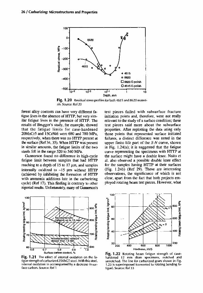
26 / Carburizing: Microstructures and Properties
loo'T""'-----------------,
o
~ -100~
~'iii -200
~"0
'gj -300a:
-400
04615D 8620
o 8620E-polish04615 E-polish
-5oo+-~ ................'"'I"":-,...............'"r--.--...-........."'"'T'"~~~~10-3 10-2 10-1 10
Depth, mm
Fig. 1.20 Residual stress profiles for both 4615 and 8620 materials. Source: Ref20
ferent alloy contents can have very different fatigue lives in the absence of HTTP, but very similar fatigue lives in the presence of HTTP. Theresults of Brugger's study, for example, showedthat the fatigue limits for case-hardened20MnCr5 and 15CrNi6 were 680 and 780 MPa,respectively, when there was no HITP present atthe surface (Ref 34, 35). When HTTP was presentin similar amounts, the fatigue limits of the twosteels fell in the range 520 to 540 MPa.
Gunnerson found no difference in high-cyclefatigue limit between samples that had HTTPreaching to a depth of 15 to 17 11m, and samplesinternally oxidized to -15 11m without HITP(achieved by inhibiting the formation of HTTPwith ammonia additions late in the carburizingcycle) (Ref 17). This finding is contrary to otherreported results. Unfortunately, many of Gunnerson's
test pieces failed with subsurface fractureinitiation points and, therefore, were not reallyrelevant to the study of a surface condition; thesetest pieces said more about the subsurfaceproperties. After replotting the data using onlythose points that represented surface initiatedfailures, a distinct difference was noted in theupper finite life part of the S-N curve, shownin Fig. 1.24(a); it is suggested that the fatiguecurve representing the specimens with HITP atthe surface might have a double knee. Naito etaI. also observed a possible double knee effectfor the samples having HTTP at their surfaces(Fig. 1.24b) (Ref 29). These are interestingobservations, the significance of which is notclear, apart from the fact that both projects employed rotating beam test pieces. However, what
20 200200 400 600 800 1000
Hardness, HV5
Fig. 1.22 Rotating beam fatigue strength of casehardened 12 mm diam specimens, notched andunnotched. The line for carburized gears shown in Fig.1.23 is superimposed (converted to rotating bending fatigue). Source: Ref 33
100100 '"E
f'" ~E ~ 800 ::EE ..>< 80~90 900 ::E "'" Ok= 1
~~ ~~ .,
.~., ~., ~ f~ 0> 60 600 .Jf80 800:1!!
0> g> I0> .5 'isc: "0 c:'is c:
~400 ic: ~.,
g> 40J:> 0>
~70 700~ "" --- ~'"~
(5 (5a: a:
a:
6O~__:;;,:;-_----:::o---~---:-::!0.6 0.7 0.8 0.9
Surface carbon content, %
Fig. 1.21 The effect of internal oxidation on the fatigue strength of carburized 25KhGT steel. With this steel,internal oxidation in accompanied by a decrease in surface carbon. Source: Ref 1

Internal Oxidation / 27
400
501--A----J+---+---=1 500
40 L--_--l.__....L__L-_..::J 400200 300 500 600
80,....----r-----,,....---r-----,
700701---+---+---+--I~q
I ~""~ ~I-_-+__~~:"-+-_~600 ~
~ 5~ u.~~
1000 r-----,-----,-------,,....----,
E~ 900 I------'-.l-~~\r_-f____,,£... 20Kh~M (10= 7 JlITl) 80 ES£ 25Mo ~h05(10=6 JlITl) ~-_8 18KhGT (10=16JlITl)
I +-~~~~~_:t+=-----+~-~~70 g~~~ I'5 ;;;j ~1§ 700 t----+---~~f___'\r_--+---___=l60 '5::>[ .S
~ Is ~O ~
~ 50 ~~ ce ~u lXl
Minimummicrohardness of surfaceof gear tooth roots, HV 0.2
w ~
Fig. 1.23 Effect of internal oxidation and surface microhardness on the fatigue properties of 4 mm modulus gears. Seealso Table 1.4. 10, internal oxidation. (a) Fatigue strength plots for 4 mm modulus gears. Information on case-hardenedgearsgiven in Table 1.4. Source: Ref26. (b) Effect of tooth root surface hardness on the bending fatigue limit of 4 mm modulus gears
(a)700HVisanextrapolation;seeFig. 1.23.(b) 80kglmrn2is takentorepresent100%fatiguestrength.
as not being detrimental, and even beneficial, tocontact durability under slide-roll test conditions.Figure 1.25 presents the contact fatigue life as afunction of the amount of material removed fromthe surface of the test disks prior to testing. Itshows that there was generally no loss of contactfatigue resistance until the internal oxidation andnonmartensitic microstructure had been removed, the depth of HTTP penetration being 25to 37 urn, Where the soft layer had been completely removed, lower values of fatigue were recorded. As a result of supporting tests, these researchers considered that plastic deformationswithin the HTTP layer, which would bring abouta more favorable distribution of contact load,could only account for part of the differenceshown. In tests where the slip was about 30%and the contact load was 2390 MPa (347 ksi),they found that the unground surface had a lowercoefficient of friction than the ground surface did
Table 1.5 Loss of fatigue strength
the two sets of results do seem to suggest is thatup to, or at, about 1()4load cycles there would beessentially no difference between the sampleswith and without HTTP.
With respect to grain size, it is interesting tonote the findings of Pacheco and Krauss in Ref30: "Fine grained gas carburized specimens tolerate the presence of inter-granular oxidation andhave better fatigue resistance than a coarsegrained specimen without surface oxidation." Intheir work, which compared plasma- andgas-carburized test pieces, the gas-carburizedspecimens contained internal oxidation to adepth of -13 urn without the HTTP associatedwith internal oxidation; this supports the ideathat, on its own, internal oxidation is not particularly damaging.
Influence on Contact Fatigue. Most casehardened gears are precision ground before going into service; therefore, the effect of internaloxidation on contact fatigue durability need not beconsidered for them. There are, however, a fewtypes of gears and a number of other componentsthat enter service in the unground, or perhaps inthe lightly lapped, condition for which the influence of internal oxidation is pertinent. Unfortunately, there are little data available on the subject, and these tend to conflict. Adverse effectshave been reported in Ref 3, whereas in Ref 36Sheehan and Howes, working with casehardened SAE 8620, regarded internal oxidation
Skin hardness, HVO.2
700(a)600500400300250
Fatiguelimit, kglmmz
80(b)72.565
-585148
Lossof fatigue streogth,'I
o9
19283640

28 / Carburizing: Microstructures and Properties
R • reheatedandquenched
D • direct quenched
2
20~----':~
30
Fig. 1.25 Contact fatigue life in relation to the amountof material removed from carburized SAE 8620 samplesprior to testing. The hatched band represents the depth ofinternal oxidation beneath the original surface of speci mens . Source : Ref36
..;;.b ---'-10.:..1_...:
2:.:;!_..;;.50.:..1_..;;.
100.:.:.,.I__2!o__...,40'
Depth 01 surfacematerial removed.I'm
1L.,1o-""""""1---.1...---.01 10
Depth 01surfacematerial removed. 0.001 in.
seem to yield results that are significantly influenced by the presence of internal oxidation andany accompanying HTIP.
Kozlovskii et aI. stated that there was no negative effect of on the impact strength of casehardened steels due to HTIP and indicated thatthere was no clear separation of bend test resultswhether the HTIP was more or less than 13 urn(Ref 1). Diesburg et aI. concluded that fracturewas independent of the structure state in theouter 0.25 mm of the case and was more dependent on the residual stresses and microstructureaway from the surface (Ref 37). Tests showedthat fracture toughness increased with distancefrom the surface (Ref 38), and that crack initiation was influenced by case hardenability (theability to produce martensite throughout thecase); crack propagation, however, was moreinfluenced by the core properties and composition (Ref 39). Feu agreed that composition wasimportant with respect to bending and impact,the resistance to these being enhanced by nickel
1100
F, fish eyeorigin
'-----'--------.l------J70010S 10S 107 10S
Cyclesto failure ("-'!)
~::::!i
1000 gfI----Ti---''.-"''''---t-----l e
1ij
g>ooo'g
I----t------;.,-'r-.---"vt--------; 1l
\ " .~••. .'1... . 800 ~• 8amples withHTTP -+-~?----l It° samples wiIhoul HTTP
- Surfaee-initialed failure••• - Subsurface failure
120
'"E 110~.>t;
+1
Ii 100~OlC
'g 90Gl.0OlC
~ 800It
7010"
(a)
1400
~ 1200::::!i
(b)
Fig. 1.24 Effectof internal oxidation and high-temperature transformation products on the high- and low-cyclebending fatigue strength. (a) Fatigue data on rotatingbeam tests, 6 mm outside diameter test section, quench860 DC into oil at 200 DC. Steel composition: 0.75 Mn,0.86 Cr, 1.48 Ni, 0.04 Mo. Samples with HTIP: 7 failed atsurface, 4 ran out , 16 failed subsurface. Samples withoutHTIP: 10 failed at surface, 2 ran out , 23 failed subsurface.Replotted from Ref 17. (b) Fatigue data for samples withand without internal oxidation, quenched from 850 DCinto oil at 70°C, temper at 180°C. Steel composition:0.74 Mn, 1.01 o.0.18 Mo. Source: Ref29
~ 1000 I---t--".;i'\<-----..-----"'-=F-'-""""',..."I--
l:l~ 800I-----l---+---,---t-£--~---:~~
J 6001-----+----+---+----+-----<>-
10" lOS 106 107
Cyclesto failure ("-'!)
(0.068 and 0.080 respectively) ; they reasoned,however, that this difference was not largeenough to account for the differences in fatiguestrength that were observed. It was concluded,although the test did not really confinn it, that itwas likely that an "as-heat-treated" surfacewould develop a more stable oil film than eithera ground or electropolished surface.
Influence on Bending and Impact FractureStrength. The fracture testing of case-hardenedsamples by slow bending or by impact (plane,notched, or precracked specimens) does not

Internal Oxidation /29
and chromium (Ref 40). Others, however, considered that static bending and impact strengthwere related to the case depth (Ref 41). Ono etaI., using unnotched impact and bend tests,showed that 930°C direct-quenched, gascarburized test pieces with 15 um of HTIP performed better than did 1040 EC vacuumcarburized test pieces with no internal oxidationor HTIP (Ref 32). A 930 EC reheat-quenched,vacuum-carburized set of test pieces producedeven better results (Fig. 1.26). Unfortunately, nodata were provided for any reheat-quenched,gas-carburized samples, so a real comparisoncould not be made. Nevertheless, the results implied that factors other than internal oxidationand the presence of HTIP were more significantwith respect to bending and impact fracture tests.
Influence on Wear Resistance. The deterioration of a surface by wear can be due to either orboth of two processes: adhesive wear and abrasive wear. Adhesive wear, as the name suggests,is adhesion that occurs when the pressure andheat generated during sliding cause small areasof one of the surfaces to chemically bond to theother surface. The relative motion breaks thebond, but not necessarily (perhaps rarely) at theoriginal junction; therefore, metal is transferredfrom one surface to the other. What happens tothe transferred particle then depends upon anumber of factors. It may remain adhered to theother surface, or it may separate to become loosedebris.
Terms for adhesive wear include scoring,scuffing, galling, and seizure. Fretting is a formof adhesive wear for which the relative movement is minute, as in the vibration between a keyand keyway, for example. Abrasive wear, or normal wear, involves the removal of particles fromthe mating surfaces by asperity shearing due toasperity collisions or collisions with loose debrispassing between the sliding surfaces. Wear pr0
cesses are appreciably influenced by any lubricant present, its quality, and its condition.
When internal oxidation is present on its ownat a case-hardened surface, one would expect itto inhibit the adhesive wear due to itsintermetallic nature. Also, as Sheehan andHowes suggested in Ref 36, the oxide could assist in the lubrication process; as it is, the oxidewill lower the coefficient of friction. The oxide,however, might favor abrasive wear and eventually crumble under the action of sliding, therebyproducing loose particles (debris). In such an instance, the depth of wear will likely be only thedepth of internal oxidation: 10 to 20 urn.
When the internal oxidation is accompaniedby the HTTP, the situation in terms of wearresistance changes. Both adhesive and abrasivewear resistances are related to the surfacehardness (Fig. 1.27, 1.28). As the hardnessfalls, the wear rates will increase, consideringthat HTTP will work harden, and martensitewill soften a little as pressure and temperatureconditions approach those that cause adhesive
4Ultimate bending
stress
,e- ......, ......" "-....... e' "-
Deflection500
2000
~::i:
lil!! 1500u;Clc:'6c:~ 1000~,§5
Crackpropagationenergy
Total energy(initiation pluspropagation)
-,
10
40
20
50
oL-.+_---\!::--_+-_-!:__..J O'~...J..__...J..__--I,,__.....!,---I
Internal Oxidation / 29
and chromium (Ref 40). Others, however, considered that static bending and impact strength were related to the case depth (Ref 41). Ono et al., using unnotched impact and bend tests, showed that 930 °C direct-quenched, gas-carburized test pieces with 15 \ua of HTTP performed better than did 1040 EC vacuum-carburized test pieces with no internal oxidation or HTTP (Ref 32). A 930 EC reheat-quenched, vacuum-carburized set of test pieces produced even better results (Fig. 1.26). Unfortunately, no data were provided for any reheat-quenched, gas-carburized samples, so a real comparison could not be made. Nevertheless, the results implied that factors other than internal oxidation and the presence of HTTP were more significant with respect to bending and impact fracture tests.
Influence on Wear Resistance. The deterioration of a surface by wear can be due to either or both of two processes: adhesive wear and abrasive wear. Adhesive wear, as the name suggests, is adhesion that occurs when the pressure and heat generated during sliding cause small areas of one of the surfaces to chemically bond to the other surface. The relative motion breaks the bond, but not necessarily (perhaps rarely) at the original junction; therefore, metal is transferred from one surface to the other. What happens to the transferred particle then depends upon a number of factors. It may remain adhered to the other surface, or it may separate to become loose debris.
Terms for adhesive wear include scoring, scuffing, galling, and seizure. Fretting is a form of adhesive wear for which the relative movement is minute, as in the vibration between a key and keyway, for example. Abrasive wear, or normal wear, involves the removal of particles from the mating surfaces by asperity shearing due to asperity collisions or collisions with loose debris passing between the sliding surfaces. Wear processes are appreciably influenced by any lubricant present, its quality, and its condition.
When internal oxidation is present on its own at a case-hardened surface, one would expect it to inhibit the adhesive wear due to its intermetallic nature. Also, as Sheehan and Howes suggested in Ref 36, the oxide could assist in the lubrication process; as it is, the oxide will lower the coefficient of friction. The oxide, however, might favor abrasive wear and eventually crumble under the action of sliding, thereby producing loose particles (debris). In such an instance, the depth of wear will likely be only the depth of internal oxidation: 10 to 20 urn.
When the internal oxidation is accompanied by the HTTP, the situation in terms of wear-resistance changes. Both adhesive and abrasive wear resistances are related to the surface hardness (Fig. 1.27, 1.28). As the hardness falls, the wear rates will increase, considering that HTTP will work harden, and martensite will soften a little as pressure and temperature conditions approach those that cause adhesive
2000
I £ 1500
I 1000
500
Ultimate bending stress
Deflection
31 c o T3 S
o "8 ' a
A a U D3 A B C D3
Load Load Fig. 1.26 Variations of (a) unnotched impact energy and (b) bending strength (15 x 60 x 2 mm). A: vacuum-carburized, 1040 °C, reheat quenched. B: vacuum-carburized, 1040 °C, direct quenched. C: vacuum carburized, 930 °C, reheat quenched. D3: gas-carburized, 920 °C, direct quenched. Source: Ref 32
Total energy (initiation plus propagation)
Crack initiation energy
/
Crack propagation energy
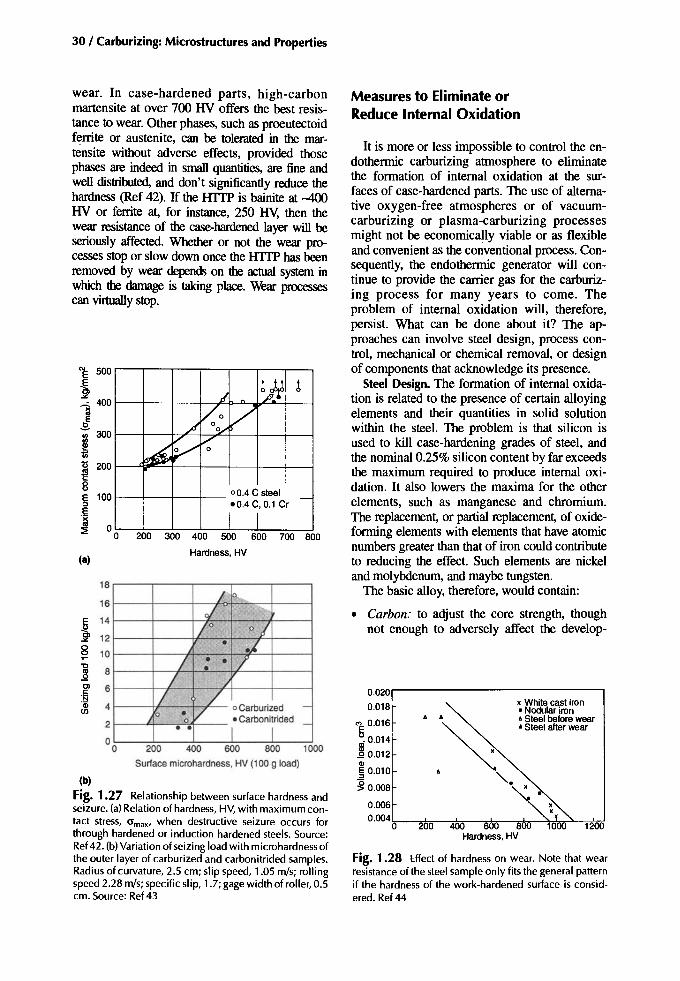
30 / Carburizing: Microstructures and Properties
(b)
Fig. 1.27 Relationship between surface hardness andseizure. (a)Relationof hardness, HV, with maximumcontact stress, am,x, when destructive seizure occurs forthrough hardened or induction hardened steels. Source:Ref42. (b)Variationofseizing load with microhardnessofthe ?uter layer of carburized and carbonitrided samples.Radiusof curvature, 2.5 cm; slip speed, 1.05 m/s; rollingspeed 2.28 mls;specific slip, 1.7; gage width of roller,0.5em. Source: Ref43
wear. In case-hardened parts, high-carbonmartensite at over 700 HV offers the best resistance to wear. Other phases, such as proeutectoidferrite or austenite, can be tolerated in the martensite without adverse effects, provided thosephases are indeed in small quantities, are fine andwell distributed, and don't significantly reduce thehardness (Ref 42). If the lITfP is bainite at -400HV or ferrite at, for instance, 250 BY, then thewear resistance of the case-hardened layer will beseriously affected. Whether or not the wear processesstopor slowdownonce the lITfP has beenremoved by wear depends on the actual system inwhich the damage is taking place. Wear processescan virtually stop.
1200
x White cast iron• Nodular iron• Steelbefore wear• Steelafter wear
• •
~. ""-.
0.020r---------------.
0.018
7: 0.016o
~~:~::CD§ 0.010
~ 0.008
0.006
O·OO4r-."k;;.---.....-k..------,;*"-"*"-~~_...,~
° 200 400 600 800Hardness . HV
Fig. 1.28 Effect of hardness on wear. Note that wearresistance of the steel sample only fits the general patternif the hardness of the work-hardened surface is considered. Ref44
Measures to Eliminate orReduce Internal Oxidation
It is more or less impossible to control the endothermic carburizing atmosphere to eliminatethe formation of internal oxidation at the surfaces of case-hardened parts. The use of alternative oxygen-free atmospheres or of vacuumcarburizing or plasma-carburizing processesmight not be economically viable or as flexibleand convenient as the conventional process. Consequently, the endothermic generator will continue to provide the carrier gas for the carburizing process for many years to come . Theproblem of internal oxidation will, therefore,persist. What can be done about it? The approaches can involve steel design, process control, mechanical or chemical removal, or designof components that acknowledge its presence.
Steel Design. The formation of internal oxidation is related to the presence of certain alloyingelements and their quantities in solid solutionwithin the steel. The problem is that silicon isused to kill case-hardening grades of steel, andthe nominal0.25% siliconcontent by farexceedsthe maximum required to produce internal oxidation. It also lowers the maxima for the otherelements, such as manganese and chromium.The replacement, or partial replacement, of oxideforming elements with elements that have atomicnumbers greaterthan that of iron couldcontributeto reducing the effect. Such elements are nickeland molybdenum, and maybetungsten.
The basic alloy, therefore, would contain:
• Carbon: to adjust the core strength, thoughnot enough to adversely affect the develop-
200 300 400 500 600 700 800
Hardness, HV
200 400 600 800 1000
Surface microhardness, HV(100 9 load)
,/ ~Jf ~-
~Vo V
°OJ
~V V0
00 .4 C steel.0.4 C, 0.1 Cr
-
I I I
/ P-oi .....
/ 0 01• .£
/ • . /•/ ,I
/ /V oCarburized -
0 •0 • Carbonitrided _
• • I I
'0
~Olc'N'CD(J)
18
16
~ 14
"" 12§ 10
(8)
E 500
~""~ 400:ll
!.j300
~ 200c8E 100:::l
.~~ 00

ment of favorable residual stresses or to encourage unwanted distortion or growth
• Nickel: to contribute primarily to the toughness of both the case and the core
• Molybdenum: to provide case and corehardenabilities, and also to suppress anyHTIP should internal oxidation occur
Added to these, optimum amounts of deoxidizingand grain-refining elements must be included,bearing in mind that these may be elements withatomic numbers lower than that of iron.Hardenability can be assisted further with moderate additionsof manganese and chromium, but lessthan 0.5% of each should be added when silicon ispresent in amounts typically 0.25%. The aim is toaccept that internal oxidation will occur to someextent but avoid the formation of significant composition gradients.
According to Kozlovskii et al. in Ref I, nickelat 1% appears to be incapable of providing thehardenability necessary to inhibit bainite formation at the boundary regions when internal oxidation and diffusion gradient have occurred. Theeffect of nickel on the hardenability of a steelpicks up somewhat when its content exceeds-1.5%, especially in the presence of molybdenum. When nickel content is higher and directquenching techniques are used, unacceptablequantities of austenite can be retained in theouter part of the case. With reheat quenching, onthe other hand, higher nickel content values canbe tolerated, although a downward adjustment ofthe surface carbon content might be prudent.
Internal oxidation has been reported inchromium-molybdenum steels, but in such casesthe molybdenum content has generally been low(-0.2%). The introduction of 0.5% (or more)molybdenum is claimed to be very beneficial, especially in those steels where molybdenum hasbeen sensibly balanced with elements having apositive oxygen affinity that also impart necessary hardenability. For example, internal oxidation to a depth of 14 to 20 urn was observed insteels with molybdenum to chromium ratios ofup to 0.4, but not in steel with a molybdenum tochromium ratio of 1 (Ref 1). With a nickelmolybdenum steel where the molybdenum tochromium ratio was 0.4 and the nickel contentwas over 1%, element impoverishment (indicated by dark etching constituents in themetallographic sample) was only observed witha reduced carbon concentration in the case.Therefore, it would seem that high-carbon surfaces are less prone to oxidation, bearing in mind
Internal Oxidation /31
that as the carbon potential rises, the oxygencontent of the atmosphere decreases. Contrary tothis, KaIner and Yurasov found that with thelean-alloy steels they studied, 0.5% molybdenumdid not prevent or reduce the internal oxidationof chromium or manganese steels (Ref 3).Chatterjee-Fischer tends to believe that as longas the accepted norm for silicon content is present in the steel, internal oxidation will occur irrespective of how the other elements are adjusted(Ref 6). Nevertheless, the presence of any alloying element must be beneficial if, for the sectionsizes being considered, it can inhibit the formation of HTIP.
Process Control. Prior to the heat-treatment ofparts in an endothermic atmosphere, precautionsshould be taken to ensure that the surfaces arefree from metal oxides (scale or corrosion products) and certain lubricants. Such surface impurities can contaminate the furnace atmosphere;they appear to influence the amount of oxidesubsequently formed and the depth to which itpenetrates (Ref 3). Furthermore, the quality ofthe machined surface can have a bearing on howwell a surface responds to carburizing. Machiningwith sharp tools, along with the use of good quality cutting lubricants, makes for uniform machining and uniform carburizing (Ref 45).
Although it is clear that internal oxidationtakes place during the carburizing operation, itcan nevertheless be intensified during anyhigh-temperature tempering cycle (carried out inair to facilitate intermediate machining operations) (Ref 15); it can also be intensified duringreheating operations, normally under atmosphere, prior to quenching. Heating in air, especially to the quenching temperature, will causescaling to occur, which might be found to scaleoff the internally oxidized layer. Subsequent shotblasting would then remove both types of oxide.This approach to internal oxide removal, whilepossible, is not really recommended due to thedifficulty of precise process control and the riskof inducing decarburization if the reheating period is lengthy.
As stated previously, internal oxidation on itsown might not be particularly damaging to fatigue resistance, whereas the presence of theHTTP can be harmful. The aim, therefore,should be to suppress the formation of HTIP. Byincreasing the cooling rate during the quenchingoperation, it may be possible to achieve this aimand thereby have only martensite associated withthe oxides. Increasing the cooling rate duringquenching could lead to distortion or growth

32 / Carburizing: Microstructures and Properties
who reduced or eliminated near-surface bainiteby increasing the carbon potential to 0.9 to 1.2%during the last 20 minutes of carburizing (Ref48). The method, it seems, does not form newcarbides but raises the carbon content of the solidsolution and, therefore, the hardenability of theouter surface.
Oxide Removal. The knowledge that internaloxidation will occur, and its confirmation bymeans of suitable test pieces that have been carburized and hardened along with the componentsthey represent, enables a manufacturerlheat -treater to develop an acceptable method forremoving the oxide and HTfP that have formed.Such methods as electropolishing, electrochemical machining, honing, grinding, grit blasting,shot blasting, or peening might be considered.Which method is used will depend upon what isavailable and what the negative effects might be;for example, grinding to remove oxides can induce tensile residual stresses of a magnitude inexcess of the tensile stresses associated with internal oxidation.
If it is essential to have an oxide-free surface,but its removal is unacceptable for some reason,then it will be necessary to consider the use of alternative carburizing processes, for example,vacuum or plasma carburizing. Nitrogen-base atmospheres and exothermic-based atmosphereswould be expected to reduce the amount of oxidation but would not eliminate it.
Part Design. It is difficult to say how the resultsof tests involving samples with test sections of 6to 8 mm and case depths of 0.5 to 1.5 mm translate to real-life components. However, these current assumptions are not unreasonable: conventional gas carburizing produces internaloxidation, Internal oxidation will likely be accompanied by HTfP, and fatigue strength will beapproximately 25% lower than for an oxide-freecounterpart. Designers may cope with these outcomes, as gear designers have done for manyyears, by having conservative basic allowabledesign stresses, or by accounting for the potential of this surface condition in their calculations.(Internal oxidation is acknowledged in gear standards like AGMA 2001, C95, or ISO 6336-5.2[1995], where acceptable amounts in relation totooth size are given. These amounts probably refer to the depth of the HTfP.) One should consider that processes, such as vacuum carburizingand plasma carburizing, while capable of producing carburized surfaces that are free from internal oxidation, can produce surfaces in whichthe austenitic grain size is coarse and the quan-
106 68 59225 133 108225 135 110
155 79 65419 161 120440 163 120
Computedtime,s,at given diametricalpitch:I 3 5
Computedtime,S, at givendiametricalpitcb:I 3 5
155 93 81880 758 733
2400 2290 2180
Computedtime,S, at givendiametricalpitch:I 3 5
Rimor bodythickness,IlL
, I 1
I • I 6U 12--------------
I I 1I I 6
U 12-=------===----===----=-=-=----
, I 1I I 6L-.: _12 _
r\ Rimor body
r' '" thiclmoss,in.
r\ Rimor bodyrl ~ thickness in.
problems, however. The critical cooling rateshave been established for a number of steels andthe optimum quenching parameters for thosesteels were determined (Ref 46). Unfortunately,as the size of the component increases, it becomes more difficult to achieve the cooling ratesnecessary to ensure the suppression of HTfP.For example, Fig. 1.29 indicates the cooling timeto 400 °C for the fillets of gear teeth of differentsizes (Ref 27). When these are used in conjunction with the continuous cooling transformation(CCT) diagrams of Fig. 1.13 and 1.14, one canloosely assess how component size might restrictthe option to increase cooling rate to suppress theformation of HTfP.
Surface hardenability and strength can be restored by the introduction of ammonia into thecarburizing chamber for a short period at the endof the carburizing cycle. Gunnerson suggested a5 to 10% ammonia addition for ten minutes before the end of carburizing (Ref 17). Using thesame guidelines, Kozlovskii et al. determinedthat a nitrogen content of 0.1 to 0.2% wasachieved in the outer 0.05 mm of surface (Ref 1).That was effective in removing the tendency toform HTfP in all but the leanest steels, and forthe leanest steels only when they were finegrained. Gu et al. determined that a nitrogen content of 0.1% in the outer 1 mm was the optimumamount (Ref 47); when nitrogen exceeded 0.1%,the crack-growth rate property increased. An alternative action was used by Zinchenko et al.,
Fig. 1.29 An indication of cooling times for gearshapes. (a) Time for gear tooth fillet surface to cool from800 to 400 °C during oil quenching. (b) Time for geartooth center on the root circle diameter to cool from 800to 400°C during oil quenching. (e) Time for rim or bodycenter to cool from 800 to 400°C during oil quenching.Source:Ref27

Internal Oxidation / 33
Summary
High-TemperatureTransformation Products
tity of retained austenite is excessive (Ref 30).The designer may have to allow for these also.
Grade 1 has no specification. Recovery by shotpeening is acceptable with agreement of the customer. Note that ISO 6336-5.2 is similar to this(ANSI!AGMA 2001-C95). The equivalent gradesare ML, MQ, and ME.
1. I.S. Kozlovskii, AT. Kalinin, AY. Novikova,E.A Lebedeva, and AI. Feofanova, InternalOxidation during Case-Hardening of Steels inEndothermic Atmospheres, Met. Sci. HeatTreat.(USSR) (No.3), March 1967, p 157-161
2. L.H. Fairbank and L.G.w. Palethorpe, "Controlled Atmospheres for the Heat Treatment ofMetals," Special Report 95: Heat Treatment ofMetals, Iron and Steel Institute, London, 1966,p 57-69
3. V.D. Kalner and SA Yurasov, Internal Oxidation during Carburising, Met. Sci. Heat Treat.(USSR) (No.6), June 1970, p 451-454
4. Y.Sun, D. Xu, andJ. Li, The Behavioroflnternal Oxidation in Gas-Carburised 20CrMnTISteel, Heat Treatment and Surface Engineering, Proc. Sixth International Congress,Chicago, 1988
5. G.V. Shcherbedinskii and AI. Shumakov, Internal Oxidation of Excess Carbides in AlloySteels during Carburising, Irv: Akad. NaukSSSR. Met., May/June 1979, (No.3), P193-199
6. R. Chatterjee-Fischer, Internal Oxidation during Carburising and Heat Treatment, Metall.Trans. A, Vo19, Nov 1978, P 1553-1560
7.I.Y. Arkhipov, V.A. Batyreva, and M.S.Polotskii, Internal Oxidation of the Case onCarburised Alloy Steels, Met. Sci. Heat Treat.(USSR), Vol 14 (No.6), June 1972, p 508-512
REFERENCES
• Preprocess considerations: Consider a steelgrade with sufficient matrix alloy in the depleted layer to give martensite on quenching.
• In-process considerations: A late increase ofcarbon potential, or a late addition of ammonia to the furnace chamber can offset the effect. Employ a faster quench to suppressHTTP formation, but watch for distortion.
• Postprocess corrections: Grinding, grit blasting and/or shot peening can be used to remove HTTP.
• Effect on properties: HTTP is soft and has anadverse effect on surface residual stresses andbending fatigue resistance-up to about 35%reduction in extreme eases. If shallow, HTTPmight have a positive effect on the contact fatigue of unground surfaces.
• Standards: No specification or guideline. Assume that HTTP should not exceed the maximum depth of internal oxidation as judgedmetallographically. See "Internal Oxidation."
Case depth
<0.030 in.0.03()...{).059 in.0.059~.089 in.0.089~.l18 in.
>O.l18in.
Grade 3
0.0005 in.0.0008 in.0.0008 in.0.0010 in.0.0012 in.
Gradel
0.0007 in.0.0010 in.0.0015 in.0.0020 in.0.0024 in.
When associated with internal oxidation,high-temperature transformation products(HTTP) are a surface effect. The formation of internal oxidation products locally denudes thematrix of certain elements. When HTTP arepresent, they often extend deeper than the internal oxidation, especially with leaner steel grades.HTTP can be avoided or controlled.
Internal Oxidation
Internal oxidation is a surface effect due to theoxidation of certain elements in the steel (mainlyMn, Cr, and Si) during carburizing. It is unavoidable in conventional gas carburizing, but can beavoided in vacuum carburizing processes.
• Preprocess considerations: Choice of steelgrade, a small uniform grain size (normalized), and essentially clean parts are factors.
• In-process considerations: The depth of oxidation relates to case-depth, and the composition of the carburizing atmosphere.
• Postprocess considerations: Internal oxidation can be removed by grit blasting and/orshot peening.
• Effect on properties: Internal oxidation possibly has a minor negative effect on bending fatigue, and a positive effect on contact fatigue.See also "High-Temperature TransformationProducts."
The following are ANSI!AGMA standards:

34 / Carburizing: Microstructures andProperties
8. C. VanThyne and G. Krauss, A Comparison ofSingle Tooth Bending Fatigue in Boron andAlloy Carburising Steels, Carburising: Processing, and Performance, G. Krauss, Ed.,ASM International, 1989, p 333-340
9. R. Chatterjee-Fischer, Zur Frage de Randoxidation bei Einsatzgeharteten Teilen,Kritische Literaturaus Wertung, HartereiTechnische Mitteilungen, (No. 28) Nov 1973,p259-266
10. C. Dawes and RJ. Cooksey, "Surface Treatment of Engineering Components," SpecialReport 95: Heat Treatment of Metals, Iron andSteel Institute, London, 1966, p 77-92
11. E. Mitchell, R.J. Cooksey, and C. Dawes,"Lean-Alloy Carburising Steels:' Publication114: Low-Alloy Steels, Iron and Steel Institute,London, 1968,31-36
12. B. Edenhofer, Progress in the Technology andApplication of In-Situ Atmosphere Productionin Hardening and Case-Hardening Furnaces,Proc. ofthe Second International Conf. in Carburizlng and Nitriding with Atmospheres,ASM International, 1995, p 37-42
13.ASM Metals Reference Book, American Society for Metals, 1981
14. K. Okasaki et al., Effect of Titanium onRecrystallisation and Grain Growth of Iron, J.Jpn. Inst. Met., Vol. 1 (No. 39), 1975, P 7-13
15. I.Y. Arkhipov, Internal Oxidation of Steel18Kh2N4Va,Met. Sci. Heat Treat. (USSR), Vol15 (No.7), July 1973, Plenum Publishing,622-624
16. N. Murai, T. Tsumura, and M. Hasebe, "Effect of Alloying Elements and Oxygen Potential at the Equilibrium Carbon Content inGas Carburising," presented at the TenthCongress of the International Federation forHeat Treatment of Surface Engineering,Brighton, 1996
17. S. Gunnerson, Structure Anomalies in the Surface Zone of Gas-Carburised Case HardenedSteels, Metal Treatmentand Drop Forging, Vol30 (No. 213), June 1963, p 219,229
18. Report No. I.S.l-888, Climax Molybdenum19. S. Preston, Influence of Vanadium on the
Hardenability of a Carburizing Steel, Carburizing: Process and Performance, G. Krauss,Ed., Conf. Proc. (Lakewood, CO), ASM International, 1989, p 191-197
20. W.E. Dowling, Jr., W.T.Donlon, ws. Copple,and c.Y. Darragh, Fatigue Behavior of TwoCarburized Low-Alloy Steels, Proc. SecondInt. Conf. on Carburizlng and Nitriding with
Atmospheres, ASM International, 1995, p55-60
21. B. Hilldenwall and T. Ericsson, ResidualStresses in the Soft Pearlite Layer of Carburised Steels, 1 Heat Treat., Vol 1 (No.3), June1980, p 3-13
22. Y.E. Smith and G.T. Eldis, ''New Developments in Carburised Steels:' Climax Molybdenum Co., Michigan, 1975
23. G.H. Robinson, The Effect ofSurface Condition on the Fatigue Resistance of HardenedSteel, Fatigue Durability of CarburizedSteel, American Society for Metals, 1957,p 11-46
24. R.L. Colombo, F. Fusani, and M. Lamberto,On the Soft Layer in Carburised Gears, J. HeatTreat., Vol 3 (No.2), Dec 1983
25. C. W. Wegst, Stahlschliissel, VerlagStahlschllissel Wegst KG, Marbach, Germany,1977, p 14
26. I.Y. Arkhipov, M.S. Polotskii, A.Y. Novikova,.SA Yurasov, and Y.F. Nikanov, The Increasein the Strength of Teeth of Carburised andCarbonitrided Gears, Met. Sci. Heat Treat.(USSR) (No. 10), Oct 1970, Plenum Publishing, p 867-871
27. G. Parrish and G.S. Harper, Production GasCarburising, Pergamon Press, 1985
28. I.Y.Arkhipov and Y.A.Kanunnikova, ResidualStresses in the Teeth of Quenched Gears, Met.Sci. Heat Treat. (USSR), (No. 11), Nov 1970, P909-913
29. T. Naito, H. Ueda, and M. Kikuchi, FatigueBehaviour of Carburised Steel with InternalOxides and Non-Martensitic MicrostructureNear Surface, Metall. Trans. A, Vol 15, July1984, P 1431-1436
30. lL. Pacheco and G. Krauss, Microstructureand High Bending Fatigue Strength of Carburised Steel, 1 Heat Treat., Vol 7 (No.2), 1989,p77-86
31. W. Beumelburg, Der Einfluss vonRandoxydation auf die Umlaufbiegefestigkeit und Statische Biefestigkeiteinsatzgehiirteter Proben, Harterei TechnischeMitteilungen, Vol 25 (No.3), Oct 1970, P191-194
32. H. Ono, K. Okamoto, and Y. Nishiyama,"Some Mechanical Properties of VacuumCarburised Steel," Paper 32, presented at HeatTreatment 1981,Sept 1981
33. H. Weigand and G. Tolasch, Dauerfestigkeitsverhalten Einsatzgeharter Proben,Hiirterei Technische Mitteilungen, Vol 22 (No.

4), Dec 1967, p 330--338 (in German; alsoavailable in English)
34. H. Brugger, Effect of Material and Heat Treatment on the Load Bearing Capacity of the Rootof Gear Teeth, VDI-Berichte, Vol 195, 1973, p135-144
35. H. Brugger, "Impact-Bending Test for the Assessment of Case-Hardening Steels," conf. paper presented to the Swiss Materials TestingAssociation
36. J.P. Sheehan and MAH. Howes, 'The Effectof Case Carbon Content and Heat Treatmenton the Pitting Fatigue of 8620 Steel," Paper720268, presented to the Society of Automotive Engineers, 1972, p 16
37. D.E. Diesburg, C. Kim, and W. Fairhurst,"Microstructural and Residual Stress Effecton the Fracture ofCase-Hardened Steels,"Paper23, presented at Heat Treatment 1981, Sept1981
38. D.E. Diesburg and G.T. Eldis, "FractureToughness and Fatigue Behaviour of Carburised Steels," Laboratory Report No.L-193-87/88, Climax Molybdenum, 1975
39. D.E. Diesburg, High Cycle and Impact FatigueofCarburised Steels, SAE Paper 780771, 1978
40. G. Fett, Bending Properties of CarburisedSteels, Adv. Mater. Process. inc. Metal Prog.,April 1988, p 43-45
41. T. Aida, H. Fujio, M. Nishikawa, and R.Higashi, Influence of Impact Load on FatigueBending Strength of Case-Hardened Gears,Bull. Jpn. Soc. Mech. Eng., Vol 15 (No. 85),1972, P 877-883
42. Y. Terauchi and J. Takehara, Paper 152-21,Bull. Jpn: Soc. Mech. Eng., Vol 21 (No. 152),Feb 1978, p 324--332
43. S.E. Manevskii and I.I. Sokolov, Resistance toSeizing of Carburised and CarbonitridedSteels, Met. Sci. Heat Treat. (USSR) (No.4),April 1977
44. T.S. Eyre, The Mechanisms of Wear, Tribol.Int., April 1978, P 91-96
45. V.I. Astraschenko and L.A. Karginova, SpottyCarburising of Steels Metallovedenie ITermicheskaya Obrabotka Metallov, June 82, p13-15
46.I.S. Kozlovskii, S.E. Manevskii, andKazachenko, Effect of Quenching Conditionson the Layer Structure and Antiseizing Stability of Carburised Steels, Metallovedenie ITermicheskaya Obrabotka Metallov, June1980, p 7-10
Internal Oxidation / 35
47. C. Gu, B.Lou, X. Jung, and F.Shen, Mechanical Properties of Carburised Co-Ni-Mo Steelswith added Case Nitrogen, 1 Heat Treat., Vol7(No.2), 1989, P 87-94
48. V.M.Zinchenko, B.V.Georgievskaya, and V.v.Kugnetsov, Improvements of the Technological Process of Automotive Parts Carburisation,Metallovedenie I Termi- cheskaya ObrabotkaMetallov, August, 1979, p 47-50
SELECTED REFERENCES
• R. Charterjee-Fischer, Cause and Effect of Internal Oxidation, Antriebstechnik, Vol 25 (No.6), June 1986, p 41-43
• R. Chatterjee-Fischer and H. Kunst, SomeConsiderations on the Property Behaviour ofSalt-Bath and Gas Carburized SpecimensMade of Steel 16MnCr5, Hart.-Tech. Mitt.,Vol 43 (No.1), JanlFeb 1988, p 41-44
• JA Colwell and R.A. Rapp, Reactions ofFe-Cr and Ni-Cr Alloys in CO/C02 Gases at850 and 950°C, Metall. Trans. A, Vol 17 (No.6), June 1986, p 1065-1074
• L. Faminski, M. Golebiowski, and J.Szawlowski, Influence of High TemperatureCarburizing on the Structure andProperties of Steel Alloyed With Titanium,Inz: Materialowa, Vol 7 (No.6), NovlDec1986, p 14fr-152
• K. Isokawa and K. Namiki, Effects of Alloying Elements on the Rotating Bending Fatigue Properties of Carburized Steels, DenkiSeiko (Electr. Fum. Steel), Vol 57 (No. 0, Jan1986, p 13-22
• H. Kanizawa and H. Satoh, Effect of AlloyingElements on the Formation of Internal Oxidation Layer in Carburized Steels, Netsu Shari(1 Jpn. Soc. Heat Treat.), Vol 37 (No.4),1997, P 225-230
• M. Kikuchi, A. Komine, and Y. Kibayashi,Influence of Internal Oxides on the FatigueStrength of Carburized Steel, I. Soc. Mater.Sci., Jpn., Vol 38 (No. 425), Feb 1989, p111-116
• Y.H. Kim and S.w. Lee, Internal OxidationControl of the Steels During Carburizing inCracked Methanol Gas Atmospheres, J. Korean Inst. Met. Maten, Vol 29 (No. 11), 1991,P 1131-1138
• T. Kimura and K. Namiki, Carburizing andFatigue Properties of Plasma CarburizedSCM 420, Denki Seiko (Electr. Fum. Steel),

36/ Carburizing: Microstructures and Properties
Vol 61 (No.1), Jan 1990, p 32-40• J.Y. Liu and S.C. Chang, The Oxidation and
Carburization of Fe-Mn-Al Alloys in a Carbon-Containing Atmoshere, Corros. Sci., Vol
39 (No.6), June 1997, p 1021-1035• G. Prunel, Internal Oxidation During the Car
burizing of Gears, Trait. Therm., Vol 197,Dec 1985, P 31-41
Chapter 2
Decarburization
Decarburization, as the term implies, is a lossof carbon atoms from the surface of theworkpiece, thereby producing a surface with alower carbon content than at some short distancebeneath the surface. If carburization promotes apositive carbon gradient, then decarburizationpromotes a negative carbon gradient.
The useful properties developed by carburizing and hardening will not be realized if theworking surface of the component becomesdecarburized. Therefore, decarburization is anunwanted metallurgical feature. The optimalamount of decarburization is regarded as beingzero, but in reality, a small amount will likely occur. A small amount of decarburization may betolerable if it is partial decarburization and penetrates no deeper than any HTTP associated withthe surface internal oxidation and it is within anyspecification for decarburization.
In well-run carburizing and hardening facilities, the decarburization of case-hardened surfaces does not seem to be a problem. This success reflects the use of good, well-maintainedequipment and good process operating procedures.Nevertheless, with case hardening, the gasmixtures employednecessarily containdecarburizingagents. As long as these agents are present, thereis always the possibility that a loss of furnace atmosphere control, for whatever reason, will leadto decarburization of the parts being treated.
Decarburization Processes
Decarburizing reactions can occur at temperatures above about 700 °C and when, in the furnace atmosphere, decarburizing agents are available to react with the carbon in the metal surface.The decarburizing agents used in furnace atrno-
spheres for carburizing and reheating are carbondioxide (COz), water vapor (HzO), hydrogen(Hz), and oxygen (Oz). Under certain conditions,these gaseous molecules can react with the carbon atoms at the gas-metal interface and therebyextract them from the surface of the metal. Thisextraction is an attempt to establish some measure of equilibrium between gas and metal. Thechemical reactions involved are:
When these reactions proceed from left toright they are decarburizing, and when they goright to left they are carburizing. There seems tobe some disagreement regarding the third reaction (involving methane) and whether it is able toproceed in both directions as reported in Ref 1. Ithas been reported as being able to proceed in onedirection only (Ref 2). If the latter is the case,then any hydrogen released by this reaction mustcombine with other component gases before itcan be an effective decarburizing agent. By combining with any oxygen in the furnace atmosphere, it will produce water vapor at the metalsurface and thereby enter into the second of thereactions shown, in a left to right direction.
Decarburizing Conditions. During carburizing,there are numerous carburizing and decarburizingreactions occurring simultaneously, with morecarburizing than decarburizing reactions takingplace (i.e., the reactions proceed from right to
Carburizing: Microstructures and Properties Copyright © 1999 ASM International® Geoffrey Parrish, p 37-49 All rights reserved. DOI: 10.1361/cmap1999p037 www.asminternational.org

38 / Carburizing: Microstructures and Properties
1000 1 h 2.5 h 1.5 h
V Presoa Carburize (935 ·C)~ (935 ·C:::J 900e8-E Atmoshpere: Equalize~ 800 20.5% CO (800 ·C)
40.0%H20.53%CH4
0.50
0.40
tft. 0.30
'"0o 0.20
0.10
00 2 3 4 5 6
Time, h
Fi~. 2.2 Complex industrial carburizing cycle. Source:ReT4
words, the carbon potential will be reduced (Fig.2.1).
Typical CO2 contents during a carburizing cycle are shown in Fig. 2.2, where an endothermiccarrier is used throughout and is enriched for thecarburizing part of the operation. Normally, theatmosphere at the end of the process, just prior tothe quench, will still be carburizing or at least ofa high carbon potential. If, however, the catalystis inefficient and, therefore, the generator gascontains more CO2 than it should, then somedecarburization is possible.
When the reheat quench process is being used,matching the atmosphere to the as-carburizedsurface carbon content might not be very precise,and a minor lowering or raising of the surfacecarbon can occur. This practice is normally accepted.
Following are some reported examples regarding the occurrence of decarburization duringhigh-temperature heating.
Gutnov et al. (Ref 5) observed that samplesplaced in a furnace at the beginning of an 800 -cheating cycle decarburized appreciably, whereasthose introduced into the furnace halfwaythrough the heating period did not decarburize(Fig. 2.3). Gutnov et al. concluded that moisturein the furnace had been responsible for the dif-
1000900800
o"- ....I- ...L.. --'
700
0.81----\--\\'\-\--\--\--+------1
left). Changes of temperature, flow rate, or composition of the atmosphere can shift the balanceso that the number of decarburizing reactionsoutstrips the number of carburizing reactions(i.e., the reactions proceed from left to right), andthe overall result is decarburization.
In an endothermic gas generator, for example,if the catalyst is in good order, the methane of theoutput gas will be <2%. The carbon dioxide andwater vapor will be present in only smallamounts, and these amounts are dependent onthe actual air/fuel ratio employed. If, on the otherhand, the efficiency of the catalyst is impaired byan accumulation of soot, for example, then thegas produced will contain greater amounts ofmethane, carbon dioxide, and water vapor (Ref 3).This increase in the proportion of decarburizingagents will lead to a reduction in the number ofcarburizing reactions taking place at anyonetime and, concurrently, an increase in the numberof decarburizing reactions taking place. In other
% CO2 + % CO= 20
1.6 t---rl-\+I-H<-'~---;-+-----\
Temperature, ·C
Fig. 2.1 Temperature and percentage of carbondioxide for equilibrium conditions with carbonsteelsof various carbon contents. Source: Ref 1
2.0t---1T-+---+-+-\-----\
tft.d' 1.2 I---\-lrt\-\I--\~----J~--t-\r------\u
0.40%C0.50%CO.60%C0.70% C-~'"0.80% C -1---*-4.'\
0.4 I----+--T-~~-k-''''<
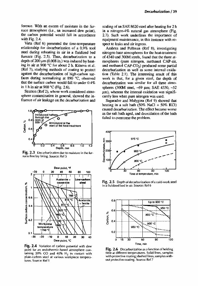
Decarburization / 39
120
120
~950°C
..~
90
Upto 900 °C
' .800°C'
'.'" '"
60 90Timeat temperature. min
o 15 30
0.8,.....-...,----,---r--------,
rfl..:~~ 0.41----+--+-~~._+--__:_t--____j
60
TIme.min
Fig. 2.6 Decarburization asa function of holdingtime at different temperatures. Solid lines, sampleswith protective coating; dashed Iines, samples without protective coating. Source: Ref 7
..............0.21----+--+---+--'-",~--__i
- ..
Fig. 2.5 Depth of decarburization of a cold-work steelin a fluidized bed in air. Source: Ref 6
411V1l'----------------.,
scaling of an SAE 8620 steel after heating for 2 hin a nitrogen-4% natural gas atmosphere (Fig.2.7). Such work underlines the importance ofequipment maintenance, in this instance with respect to leaks and air ingress.
Ambrus and Pellman (Ref 8), investigatingnitrogen-base atmospheres for the heat-treatmentof 4340 and 300M steels, found that the three atmospheres (pure nitrogen, methanol CAP-air,and methanol CAP-C02) produced some partialdecarburization as well as some internal oxidation (Table 2.1). The interesting result of thiswork is that, for a given steel, the depth ofdecarburization was similar for all three atmospheres (300M steel, -69 urn; SAE 4330, -52urn), whereas the internal oxidation was significantly less when pure nitrogen was used.
Sagaradze and Malygina (Ref 9) showed thatheating in a salt bath (50% NaCl + 50% KCl)caused decarburization. The effect became worseas the salt bath aged, and deoxidation of the bathfailed to overcome the problem.
Dew point. OF20 40 60
0.1 '---'---'---........................................._.u..J,----J
-30 -20 -10 0 10 20 30 40Dew point. °C
Fig. 2.4 Variation of carbon potential with dewpoint for an endothermic-based atmosphere containing 20% CO and 40% H2 in contact withplain-carbon steel at various workpiece temperatures. Source: Ref 1
Int?oduced halfwathroughthe 0
• 0.8 soak at \?J' 800 °C Introducedat theg 0 start of the heat treatmente~
ference. With an excess of moisture in the furnace atmosphere (i.e., an increased dew point),the carbon potential would fall in accordancewith Fig. 2.4.
Virta (Ref 6) presented the time-temperaturerelationship for decarburization of a 0.9% toolsteel during reheating in air in a fluidized bedfurnace (Fig. 2.5). Thus, decarburization to adepth of 200 urn (0.008 in.) was induced by heating in air at 900 °C for about 2 h. Kileeva et al.(Ref 7), studying methods of coating to protectagainst the decarburization of high-carbon surfaces during normalizing at 890°C, observedthat the surface carbon would fall to under 0.4%in 1 h in air at 900 °C (Fig. 2.6).
Stratton (Ref 2), whose work considered atmosphere contamination in general, showed the influence of air leakage onthe decarburization and
0.2 0.4 0.6 0.8 1.0 1.2Depth.mm
Fig. 2.3 Decarburization due to moisture in the furnace fireclay lining. Source: Ref 5

40 I Carburizing: Microstructuresand Properties
10r----,------------,---,
to that steel. Theoretically, an endothermic carrier gas, perhaps with a slight enrichment (e.g.,0.5% C potential), should have been adequate.The tests showed that to obtain the best resultsthe atmosphere had to be carburizing. Anythingless resulted in a reduced hardness and residualtensile stresses at the surface (Table 2.2).
The Physical Metallurgy of Decarburization. Ifa carburized steel is in the austenitic condition ata temperature above the AC3 (e.g., 900 "C) and ifthe furnace atmosphere is decarburizing (i.e., thereactions proceed from left to right), then carbonatoms will leave the surface in an endeavor to restore equilibrium with the surrounding furnaceatmosphere. A negative carbon gradient is produced with carbon atoms feeding down the gradient. The surface carbon content is determinedby the carbon potential of the atmosphere. If thepotential is low, the surface carbon content willbe correspondingly low. The depth of thedecarburized layer is determined by the length oftime that the part resides in the outlined furnaceconditions. At temperatures below the AC3 andabove the ACt, including those used for reheatingand quenching (800 to 840°C), thedecarburizing reaction is somewhat different(Ref 11). At these temperatures, the carbon content of the immediate surface (originally A inFig. 2.8 and 2.9a) rapidly falls to the valueshown by B. Any further lowering of the carboncontent must result in a material of carbon con-
,I
II
II
Partialdecarburization
Variableresultsdue to oxidation
,,,,,,8
6 Totaldecarburization
;II..:«
4
0.1 0.2 0.3Depth of carburization. mm
Fig. 2.7 Effect of leak rate on the decarburization ofSAE 8620 after 2 h at 850°C in a nitrogen/4% natural gasatmosphere. Source: Ref 2
The choice of atmosphere carbon potential forreheating prior to quenching is most important.Naisong et al. (Ref 10), with a 52100 steel(-1.02% C) and a reheating temperature of 810°C, employed endothermic atmospheres withcarbon potentials between 0.15 and 0.9% to determine which carbon potential was best suited
Table 2.1 Laboratory results: effectofatmospheres on high-strength steelsDepth ofdecarhurizalion."m (ilL) Deplh ofinlergranularaltack,,,m(jJilL) Average lensile s1renglh,
Almosphere Average Siandarddevialion Average Siandarddevialion MPa(ksl)
4330
Nitrogen 48(0.0019) 20.3 (0.00080) 0.5 (20) 0.5 (20) 1627(236)MethanolCAP-air 58(0.0023) 7.9 (0.00031) None visible None visible 1658(240.5)MethanolCAP-CO2 51 (0.0020) 7.9 (0.00031) 11.2(440) 1.0 (40) 1612(233.9)
300M
Nitrogen 66(0.0026) 19.8(0.00078) 1.0(40) 2.5 (100) 2013 (292)MethanolCAP-air 69(0.0027) 0 4.1 (160) 1.0(40) 2015 (292.3)Methanol CAP-CO2 69(0.0027) 0 5.8 (230) 0.8(30) 2025 (293.7)
Source:Ref 8
Table2.2 Effect ofcarbonpotential on microstructure, hardness, and residual stresses ofa 52100steel(1.02%C)duringreheating priorto quenchingAtmospherecarbonpotentialzeyo Relained auslenite, % Carbides, % Hardness(a), HK Surface residualslresses, MPa0.9 17.4 16 820 -400.7 9.8 12 811 +100.5 6.2 8.5 751 +1400.3 2.5 7 695 +2700.15 2.0 7 626 >270
Reheated10 810 DC for I h, oil quenchedat 55 DC, temperedat 150DC for 2 b. HK,Knoop hardnessnumber.(a) I kg load. Source:ReflO

tent C being formed in equilibrium with materialof carbon content B. Therefore, because the atmosphere is decidedly decarburizing in nature, afurther lowering of the average surface carboncontent must result in the development of ferritecontaining carbon to the equilibrium value C(curve 2, Fig. 2.9a). This layer, once it becomescontinuous, reduces the rate of decarburizationbecause, in the low-carbon ferrite layer, the carbon activity is reduced. Further, because the ferrite can have only a shallow gradient across it,the rate of flow of carbon atoms through thelayer is also reduced. As the ferrite layer increases in thickness, the decarburizing rate isfurther reduced due to the decreasing effectiveness of the driving force responsible for movingcarbon atoms through the layer. Behind the ferrite layer, the carbon gradient in the austenite becomes more gradual with time as carbon feedsdown to the interface with the ferrite layer (curve3, Fig. 2.9a).
l!!aeQ)a.E{!!
Carbon,%
Fig. 2.8 Iron-carbon equilibrium diagram used to explain decarburization
Ar-;;zr'7""'-----.....,
Increasingtime
B
Decarburization /41
When a controlled atmosphere is employedwith a carbon potential of some value between Aand B (Fig. 2.8), such as D, then a ferrite layercannot form, Instead, a gradient is produced between carbon contents A and D (curve 1, Fig.2.9b). With time the gradient becomes flatter(curves 2 and 3, Fig. 2.9b) until eventually nogradient to the surface exists (curve 4, Fig. 2.9b).
The two-stage carburizing method utilizes thisgradient depletion process. In the first stage, ahigh carbon potential is employed to produce ahigh-carbon surface (e.g., 1.2% C). For the second stage, the carbon potential is reduced to produce the specified surface carbon content (e.g.,0.85% C). Carbon diffuses both inward and outward, and the end result is a carbon gradient witha surface carbon plateau at 0.85%. Too short aduration or too high a CO2 content for the second stage results in a carbon gradient with a negative slope at the surface (Fig. 2.10). A negativecarbon gradient formed in this way does not leadto a rejection, provided the surface carbon content and the surface hardness are each withintheir specified range. Nevertheless, detection ofthis problem should lead to a reassessment of appropriate process parameters. A negative carbongradient of this type could produce an acceptablemartensitic microstructure at the surface with asubsurface microstructure that contains excessiveamounts of carbides or retained austenite.Whether or not such a combination of microstructures is accepted depends on the application.
Testing
Testing for Decarburization. Heat-treatmentoperators go to great pains to avoid classicaldecarburization because of its adverse effects. Its
time
C CL...- -I .... ---J
Depthbelowsurface Depthbelowsurface
Fig. 2.9 Effect of carbon potential on the surface carbon of adecarburized surface. (a) Atmosphere decarburizing: carbon potentialless than B.(bl Atmosphere decarburizing: carbon potentialequals D

42 / Carburizing: Microstructures and Properties
(b)
Fig. 2.11 Micrographs showing different degrees ofdecarburization. (a) Total decarburization caused by severe furnace leak during gas carburization of 1018 steel(l % nital etch, 500x). (b) Partially decarburized specimen. 190x
(a)
HTIP only. With still more surface carbon (say,0.4-0.5%), the microstructure of the decarburized layer might be martensitic. However, thismartensite, having a low carbon content, willnital etch to be more gray in color than would ahigh-carbon martensite, and, therefore, this levelof decarburization should be detectable metallographically. For a given loss of surface carbon,the final microstructure will depend on the alloycontent of the steel and the cooling rate. (See Fig.1.13a and b and Fig. 1.14 for examples.)
1.4
EN32A(0.029%AI)3
5
Carburizingat 925 'C
1 For 16 h at 0.16% CO22 For 8 h at 0.1%C02+ 1.25h at 0.175%C02:-'l"~~
3 For 8 h at 0.1% CO2 +2.5 h at 0.175%CO2 --,:--t-;;----,;----t
4 For 8 h atO.1% CO2 +4 h at 0.175%CO25 For8hatO.1%C02+1 hatO.25%C02
0.2
0.1
0!:---:-:-:::--"'~--=-=---=,"=---;'-;:----7:=----;'o
0.9 r--;;-.,.-~"...-,...---'------'----,---,
0.8~~~t:----r----=-T4=---r-------j0.717"''t--''''-e:--'''''~'''''''':-+----+--+---+----j
0.61----+----?'-""""-,-------1""IIk.---I---+-_+-_____1'if.C 0.5 ~-+---t--__t_"'''''-:----f''Iho:-+-_+-_____1o~ 0.4
U 0.3
0.2 0.4 0.6 0.8 1.0 1.2Depth belowsurface. mm
Fig. 2.10 Typesof carbon profiles. Source: Ref 12
detection, through macrohardness and/or microhardness testing, metallography, carbon analysis,or all three, will lead to the need to rework ormore probably the rejection of the affected components. An occurrence of decarburization mightbe suspected if something untoward happenedduring the heat-treatment sequence. Such a suspicion precipitates action to determine if theheat-treated parts suffered as a result of the operating problem.
Soft surfaces, determined during routine quality testing of the components (by file or hardnesstest) or of test pieces that accompany the furnaceload, will only indicate that something is wrong.Soft surfaces can occur due to high-temperaturetransformation products (HTIP) that accompanyinternal oxidation, excessive retained austenite,nonmartensitic structures resulting from either a"slack" quench or a steel with an uncharacteristically low hardenability (extremely fine-grained),or decarburization. The first action taken mustdetermine exactly which of the possibilitiescaused the soft skin effect.
The Metallography of Decarburization. Decarburization is classified as either total or partial.Total decarburization refers to the removal of essentially all the carbon from the immediate surface; the polished and etched surface microstructure is ferritic (Fig. 2.11a). It will likelyhave a layer of partial decarburization beneath it.Partial decarburization is any surface carbon lossthat is not sufficient to produce total decarburization (a condition somewhere betweencurves 1 and 2 in Fig. 2.9a). Many consider partial decarburization to be that which occurs whenmetallography detects HTIP and grain-boundaryferrite at the surface of the part (Fig. 2.11b). Forsuch a microstructure, the surface carbon contentwould be quite low. With a little more surfacecarbon, the microstructure might consist of

The surfaces of quenched parts that have suffered partial decarburization will likely bebainitic or even martensitic depending on the alloy content. A bainitic structure at the surface isdistinct compared to the underlying martensite.Although in a well tempered structure (dark etching), it might not be too apparent at first sight.Low- to medium-carbon martensites in a quenchedand tempered surface (through the microscope) appearto be more gray thanthe higher-carbon material beneath the affected layer.
Any indication that a surface is decarburizedjustifies a microhardness traverse being carriedout. Small amounts of decarburization might notbe too obvious, metallographically or in terms ofa microhardness traverse. However, a good densemartensitic surface layer with free carbides orfair amounts of retained austenite beneath it is anindicator of a negative carbon gradient (uppercurve, Fig. 2.12b). It is then necessary to conductchemical analysis to confirm any suspicions ofthis condition.
Influence on Material Properties
Influence on Hardness. Shallow decarburization,or a minor reduction of the surface carbon content, does not greatly influence the surfacemacrohardness of a case-hardened part. In such
Decarburization / 43
an instance, the hardness could be either increased or decreased by some small, andpossibly insignificant, amount. Hardness increases are obtained when decarburization is responsible for lowering the retained austenitecontent consequently increasing in themartensite produced; the carbon gradient for thisis similar to the upper curve of Fig. 2.12(b).Hardness reductions are obtained when low-carbon martensites or bainites are produced from acarbon gradient such as Fig. 2.12(a). If the reduced hardness resembles a "skin" effect, itmight not be detected by macrohardness testing.Microhardness testing, however, is expected todetermine the presence of such microstructures.For the relationship between hardness and carbon content for the different microstructures, seeFig. 1.18.
With severe decarburization, even if proeutectoid ferrite is not formed, appreciable amounts ofother low-carbon transformation products occurat the surface. This presence of decarburizationcan be detected by macrohardness testing. However, it should be remembered that surface softness can also be caused by high levels of retained austenite or excessive amounts of H1TPassociated with internal oxidation, in which caseit is necessary to utilize metallography to determine the cause. Having said that, for a givendepth of H1TP associated with internal oxida-
Distance from surface Distance from surface
1ftc-
~oso
Distance from surface
F M MB +M A
> 800J:<Ii:ll 700c'EosJ:
600
M M
500'-- -'
Distance from surface Distance from surface Distance from surface
(a) (b) (e)
Fig. 2.12 Influence of decarburization on hardness profiles. F, ferrite; B, bainite; M, martensite; A, austenite. (a) Severe decarburization. (b) Slight decarburization. (c) No decarburization
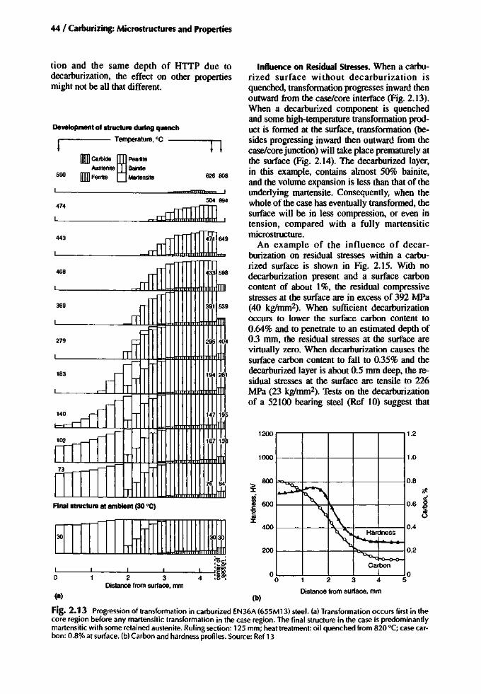
44 / Carburizing: Microstructures and Properties
0.4
0.2
1.2
1.0
0.8
o5432
Distance from surface, mm
~.--~"'"~~
'\: I"A-. Ha~ness
I~
ca~on
200
oo
400
1000
1200
(b)
800s:l'i~600'E'":r
Influence on Residual Stresses. When a carburized surface without decarburization isquenched, transformation progresses inward thenoutward from the case/core interface (Fig. 2.13).When a decarburized component is quenchedand some high-temperature transformation product is formed at the surface, transformation (besides progressing inward then outward from thecase/core junction) will take place prematurely atthe surface (Fig. 2.14). The decarburized layer,in this example, contains almost 50% bainite,and the volume expansion is less than that of theunderlying martensite. Consequently, when thewhole of the case has eventually transformed, thesurface will be in less compression, or even intension, compared with a fully martensiticmicrostructure.
An example of the influence of decarburization on residual stresses within a carburized surface is shown in Fig. 2.15. With nodecarburization present and a surface carboncontent of about 1%, the residual compressivestresses at the surface are in excess of 392 MPa(40 kg/mm 2). When sufficient decarburizationoccurs to lower the surface carbon content to0.64% and to penetrate to an estimated depth of0.3 mm, the residual stresses at the surface arevirtually zero. When decarburization causes thesurface carbon content to fall to 0.35% and thedecarburized layer is about 0.5 mm deep, the residual stresses at the surface are tensile to 226MPa (23 kg/mm-). Tests on the decarburizationof a 52100 bearing steel (Ref 10) suggest that
626 808
I
4I
2 3Distance from surface, mm
DIlll Carbide ~ Pea~lteAustenite Bainije
lIIIJ Ferrite Martenslte
474
590
r-
Jo 3l30~~T 1'1. ,
(a)
504 694
'----_--=rrfriJJJJIWJL
Final structure at ambient (30 ·C)
Development of structure during quench
----- Temperature,·C ----n
tion and the same depth of HTTP due todecarburization, the effect on other propertiesmight not be all that different.
Fig. 2.13 Progression of transformation in carburized EN36A (655M13) steel. (a) Transformation occurs first in thecore region before any martensitic transformation in the case region. The final structure in the case is predominantlymartensitic with some retained austenite. Ruling section: 125 mm; heat treatment: oil quenched from 820°C; case carbon: 0.8% at surface. (b) Carbon and hardness profiles. Source: Ref 13
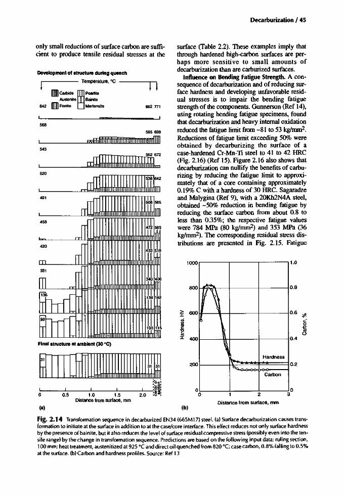
Decarburization / 45
585698
dililllilllllilillililililllilililiifIIl]
1.0
0.8
0.2
0.6 <fc
S0.4
o32
Distance from surface, mm
~
rt~
\,Hardness
~
%
Carbon
oo
200
800
1000
(b)
surface (Table 2.2). These examples imply thatthrough hardened high-carbon surfaces are perhaps more sensitive to small amounts ofdecarburization than are carburized surfaces.
Influence on Bending Fatigue Strength. A consequence of decarburization and of reducing surface hardness and developing unfavorable residual stresses is to impair the bending fatiguestrength of the components. Gunnerson (Ref 14),using rotating bending fatigue specimens, foundthat decarburization and heavy internal oxidationreduced the fatigue limit from -81 to 53 kg/mm-,Reductions of fatigue limit exceeding 50% wereobtained by decarburizing the surface of acase-hardened Cr-Mn-TI steel to 41 to 42 HRC(Fig. 2.16) (Ref 15). Figure 2.16 also shows thatdecarburization can nullify the benefits of carburizing by reducing the fatigue limit to approximately that of a core containing approximately0.19% C with a hardness of 30 HRC. Sagaradzeand Malygina (Ref 9), with a 20Kh2N4A steel,obtained -50% reduction in bending fatigue byreducing the surface carbon from about 0.8 toless than 0.35%; the respective fatigue valueswere 784 MPa (80 kg/mm-) and 353 MPa (36kglmm2) . The corresponding residual stress distributions are presented in Fig. 2.15. Fatigue
662 nl
2.0
545
IIIIIl Carbide ~ PearliteAustenite Bainite
642 [Ill Ferrite Martensite
568
~
31
~ lJ Jl~ h- n.lli.
0.5 1.0 1.5Distance from surface, mm
(a)
Development of structure during quench
----- Temperature, DC ----ll
Final structure at ambient (30 DC)
only small reductions of surface carbon are sufficient to produce tensile residual stresses at the
Fig. 2.14 Transformation sequence in decarburized EN34 (665M17) steel. (a) Surface decarburization causes transformation to initiate at the surface in addition to at the case/core interface. This effect reduces not only surface hardnessby the presence of bainite, but it also reduces the level of surface residual compressive stress (possibly even into the tensile range) by the change in transformation sequence. Predictions are based on the following input data: ruling section,100 mm; heat treatment, austenitized at 925°C and direct oil quenched from 820 °C; case carbon, 0.8% falling to 0.5%at the surface. (b) Carbon and hardness profiles. Source: Ref 13

46 / Carburizing: Microstructures and Properties
Core carbon, %
Fig. 2.16 Effect of decarburization on the bending fatigue strength of a Cr-Mn-Ti steel of varying core carbon.Source: Ref 15
~1000 I800
1200
2
Core
Ki=1.55
EN36Total case 2.5 mmSurface0.94%C
0.5 1 1.5Distancefromsurface,mm
3000L_-'----'_.........._ _'_--0._........_"'-.......
(8)
90 .-----r-~-___r----,r_:_;_-:-::-:-"l14oo
~ 70~g 60
150
80
40
800 ...-........-......----...---.--....---.--.----.~ Decarburtzatlon free~ 700 - ......_~
:I: "• 600 r Decarburtzedc ,1: 500 :~ I
.~ 400 I:0
301()3 104 105 106 107(b) Cycles
Fig. 2.17 Effect of decarburization in carburizedEN36 0.16% Ni, 0.9% Cr) steelon (a)microhardness and(b) bending fatigue strength
decarburized surface would be detrimental to thecontact durability of a carburized and hardenedpart. In the absence of test data, it is impossibleto determine what would happen if adecarburized part were to enter service. Naturally, it greatly depends on how much rolling andsliding are involved, what the contact pressure is,and how severe the decarburization is.
Consider a SAE 8620 part manufactured tofunction as a case-hardened part, which has adecarburized surface carbon content of only0.45% and a penetration depth corresponding tomaximum shear. Early contact cycles deform thesofter surface layers and thereby quickly contribute to a good load distribution. At the same time,the soft material work hardens to improve its resistance to wear. However, it can only be deformed so much before it becomes overworkedand the amount of spreading gives rise to extreme tensile residual stresses. These stresses occur in a narrow zone somewhere within thedecarburized layer and possibly close to the interface with harder underlying carburized material. The outcome of that circumstance is surfacespalling, which involves flakes of work hardenedsurface being detached from the surface. Thetime to failure would not be long.
If the amount of decarburization was confinedto the outermost 75 urn, for example, then theadverse effects of decarburization might not begreat. See the corresponding section in Chapter1, "Internal Oxidation," with attention to thework of Sheehan and Howes.
200
400~.~1iiu.
600
200 8!:::lE
o i~"C'0;
200 l2
•(52)
0.4
-v-__..ll800
•(SO)
0.3
• •(38) (45)
0.2
•(24)
3.5Ni-l.5Cr I~
r-, / I.-, II Vy1\ r..J v
/
""' \ ~V /1\ ' ~
v .-/~
1\~V/ Case
........V depth --=.1
20 -(12)
0.1
70 0 Carburized, 1.2mmcaseD Decarburized to
41-42 HRCat surface• Not carburized-numbers
in parentheses giveapproximate HRC
30
40
30
'" 20E.€
10~<IifI.l 0i"iii -10:::>
"C'0; -20Q)
II:-30
~ ~OO
-50o 0.2 0.4 0.6 0.8 1.0 1.2 1.4 1.6 1.8
Fig. 2.15 Effect of decarburization on the residualstresses developed in carburized and hardened plates.The carbon content at 0.002 mm was estimated to be 1%(curve 1),0.64% (curve 2), and 0.35% (curve 3). Source:Ref 9
tests, using notched test bars that simulated a 13mm modulus gear (-2 diametrical pitch),showed that the fatigue limit was reduced by almost 40% on those samples decarburized to adepth of 0.22 mm (Fig. 2.17). Kileeva et al. reported reductions of fatigue strengths of 19% inone case and 35% in another case from the decarburization that occurred during post-carburizingnormalizing or hardening heat treatments (Ref7). The microstructure of the decarburized layerhas the most influence on the fatigue strength;the depth of decarburization (within reason) andthe microstructure of the underlying material areprobably not very significant.
Influence on Contact Fatigue. Contact fatigueresistance is related to the shear strength of thematerial; therefore, it would be expected that a

Influence on Bending and Impact. Decarburization does not necessarily reduce the staticbending strength of case-hardened surfaces (Ref9). As Table 2.3 shows, bend strength peakswhen the surface carbon content is 0.6%, despitethe almost zero residual stresses at the surface.Presumably, this corresponds to the highest carbon content that produced only martensite.
Influence on Wear. The adhesive and abrasivewear resistance of a case-hardened surface is adversely affected by decarburization to a degreerelating to the surface hardness (see Fig. 1.27).
Control of Decarburization
Severe decarburization of case-hardened partsoccurs only rarely, especially with modem atmosphere monitoring systems and when furnacescan be nitrogen purged at the first signs of trouble. Even improvements in health and safetymonitoring mean safer handling ofparts, so thereis less risk of accidents occurring during transferof parts from furnace to quench. The risk of encountering decarburization is further reduced byhaving good plant maintenance, good supervision, and sound process control.
The less obvious type of decarburization (i.e.,caused by too short a diffusion stage or an incorrect atmosphere adjustment in the boost/diffusemethod) is fairly easy to correct. It is importantto be able to detect that there is a problem.
Table 2.3 Effectof decarburization on the fatigueand bending strength of case-hardened 20Kh2N4AsteelSurfacecontent, Fatiguestrell&th Bendstrength% (atmosphere) (o-I),MPa (0 hend),MPa
Normallzed(a)
1.04 (not normalized) 80 3190.8 (gas furnace) 81 355<0.8 (nitrate salt) 77 3180.6 (chloride bath. 20 min) 60 4070.35% (chloride bath. 160 min) 39 318
Not normallzed(b)
0.16 45 2760.51 50 3430.63 49 4120.84 57 3501.05 51 307
(a) Carburized, normalized at 890 °C. high-temperature tempered andquenched from 800 "C, then tempered to 140 "C. (b) Carburized,high-temperature tempered. heated in chloride bath for various timesto decarburize, oil quenched at 800 °C, then tempered to 140 °C.Source: Ref9
Decarburization I 47
Rectification of components once they arefound to be decarburized depends on a numberof factors. Questions must be asked and answered. For example, does the amount of decarburization measured render the part useless? Isthe item to be stressed to its undecarburized limitin service, or is there a fair safety margin builtinto the design? If the decarburization is shallow,can it be grit blasted in the critical areas to remove the affected layer and shot peened to ensure surface compression? If the decarburizationis deeper than what can be reasonably grit blastedand shot peened, can the part be recovered byreclamation heat treatment (Ref 16)? It must bekept in mind that any reheat treatment could induce additional shape and size changes (distortions) that on their own could warrant a rejectionof the part.
Each incident of decarburization must be assessed on its own; what might work for one partdesign might not be applicable to another. Theeconomics of encountering decarburization isobviously an important consideration. Whateveraction is taken to recover the situation, the primary consideration should be with respect to thecomponent and its eventual fitness for service.
Summary
Decarburization can occur when surface carbon is slightly lower than at depth due to an incorrect diffuse stage of a boost-diffuse carburization program. Surface carbon is adequate ifacceptable hardness is achieved. This conditionis not serious. When surface carbon is moderateto very low, decarburization is detectable byhardness test and by metallographic methods.This condition is unacceptable, as it may resultin a failure.
• Preprocess considerations: Good maintenance of equipment is essential. Decarburization might signify an equipment failure.Long reheating times in air are not recommended.
• In-process considerations: Atmosphere monitoring system might indicate a problem. Reheating in air is not recommended.
• Postprocess considerations: Post-process corrections depend on the degree of decarburization. For shallow partial decarburization,consider shot-peening. For deeper total orpartial decarburization, consider restoration

48 / Carburizing: Microstructures andProperties
carburizing if added distortion can be tolerated.
• Effecton properties: Significantdecarburizationleads to incorrect surface microstructures andlow hardness values. If surface carbon isgreater than 0.6%, the surface hardnessshould be acceptable. If surface carbon is approximately 0.6% or less, all the main properties will be adversely affected, for example,bending fatigue could be reduced by 50%.
• Standards: ANSJlAGMA 200I-C95: no specification for grade I. For grade 2 and grade 3,no partial decarburization is apparent in outer0.13 mm (0.005 in.) at 400>< except in unground TOOts. IS06336-5.2: for MQ and MEgrades, the reduction of surface hardness dueto decarburization in the outer OJ mm (0.004in.) should not exceed 2 HRC on the test bar.
REFERENCES
1.Heat Treating, Vol 4, Metals Handbook, 9thed., American Society for Metals, 1981
2. P.E Stratton, Living with Furnace AtmosphereContamination, Heat Treat. Met., 1984, Vol 2,p41-48
3. L.H. Fairbank and L.G.W Palethorpe, ''Controlled Atmospheres for the Heat Treatment ofMetals," Heat Treatment ofMetals, Special report 95, Iron and Steel Institute, 1966,p 57-69
4. FA Still and H.C. Child, Predicting Carburising Data, Heat Treat. Met; 1978, Vol 3, p67-72
5.R.B. Gutnov, L.P. Emel'yanenko, E.N.Samsonova, L.A. Shvartsman, and D.D.Shishlov, Sources of Decarburisation duringthe Restoration Case-Hardening of Steel inBell Furnaces, Stahl, (No. 11), Nov 1971, p1039-1040
6. Virta, Heat Treatment '84 (London), TheMetals Society, 1984
7. A.1. Kileeva, D.1. Potoskveva, and V.S.Sagaradze, Prevention of Decarburisation withEnamel Coat, Met. Sci. Heat Treat. (USSR),(No. 10), Oct 1975, p 68-70
8. Z. Ambrus and MA Pellman, Hardening ofAerospace Alloys in Nitrogen Based Atmospheres, Met. Prog., May 1983, p 47-51
9. Y.S. Sagaradze and L.Y. Malygina, Influenceof Decarburisation on the Properties ofCase-Hardened Steel, Metal Sci. Heat Treat.(USSR), (No.7), July 1966, p 560-563
10.X. Naisong, CA Stickels, and C.R. Peters,The Effect of Furnace Atmosphere Carbon Po-
tential on the Development of ResidualStresses in 52100 Bearing Steel, Metall. Trans.A, Vol 15, Nov 1984, p 2101-2102
11. WA. Pennington, A Mechanism of the SurfaceDecarburisation of Steel, Trans. ASM, 1946,Vol 37, p 48-91
12. R. Collin, Mathematical Model for PredictingCarbon Concentration Profiles, J. Iron SteelInst., Oct 1972
13. D.W Ingham and P.C. Clarke, Carburise CaseHardening-Computer Prediction of Structureand Hardness Distribution, Heat Treat. Met.,1983, Vol 4, p 91-98
14. S. Gunnerson, Structure Anomalies in the Surface Zone of Gas-Carburised Case-HardeningSteels, Met. Treat. Drop Forging, Vol 30 (No.213), June 1963, p 219-229
15.V.S. Sagaradze, Effect of Carbon Content onthe Strength ofCarburised Steel, Met. Sci. HeatTreat. (USSR), (No.3), March 1970, p198-200
16.Y.G. Koroshailov, E.L. Gyulikhandanov, andY.Y. Kislenkov, Restoration Carburising ofSteel ShKhl5 in Endothermic Atmosphere,Met. Sci. Heat Treat. (USSR), (No. 12), Dec1975, P 33-35
SELECTED REFERENCES
• P. Baldo and E. Duchateau, "Process for HeatTreatment Under a Gaseous AtmosphereContaining Nitrogen and Hydrocarbon," U.S.Patent US4992113, 22 Aug 1990
• MJ. Gildersleeve, Relationship Between Decarburisation and Fatigue Strength of ThroughHardened and Carburising Steels, Mater. Sci.Technol., Vol7 (No.4), April 1991,p 307-310
• H.I. Grabke, E.M. Muller, H.Y. Speck, and G.Konczos, Kinetics of the Carburization ofIron Alloys in Methane-Hydrogen Mixturesand of the Decarburization in Hydrogen, SteelRes., Vol 56 (No.5), 1985, p 275-282
• B. Korousic and B. Stupnisek, Predicting ofReactions during Carburization and Decarburization of Steels in Controlled Atmospheres,Kovine Zlitine Tehnol., Vol 30 (No.6), NovlDec1996, p 521-526
• G. Matamala and P. Canete, Carburization andDecarburization Kinetics of Iron in 04-H2Mixtures between 1000--1100 "C, Mater. ChemPhys., Vol 12 (No.4), April 1985,p 313-319
• M. Renowden, O. Borodulin, and P. Baldo,Unique Atmosphere Control System for Carbon
48 / Carburizing: Microstructures and Properties
carburizing if added distortion can be tolerated.
• Effect on properties: Significant decarburization leads to incorrect surface microstructures and low hardness values. If surface carbon is greater than 0.6%, the surface hardness should be acceptable. If surface carbon is approximately 0.6% or less, all the main properties will be adversely affected, for example, bending fatigue could be reduced by 50%.
• Standards: ANSI/AGMA 2001-C95: no specification for grade 1. For grade 2 and grade 3, no partial decarburization is apparent in outer 0.13 mm (0.005 in.) at 400x except in un-ground roots. IS06336-5.2: for MQ and ME grades, the reduction of surface hardness due to decarburization in the outer 0.1 mm (0.004 in.) should not exceed 2 HRC on the test bar.
REFERENCES
1. Heat Treating, Vol 4, Metals Handbook, 9th ed., American Society for Metals, 1981
2. P.E Stratton, Living with Furnace Atmosphere Contamination, Heat Treat. Met., 1984, Vol 2, p 4 1 ^ 8
3. L.H. Fairbank and L.G.W. Palethorpe, "Controlled Atmospheres for the Heat Treatment of Metals," Heat Treatment of Metals, Special report 95, Iron and Steel Institute, 1966, p 57-69
4.F.A. Still and H.C. Child, Predicting Carbu-rising Data, Heat Treat. Met., 1978, Vol 3, p 67-72
5.R.B. Gutnov, L.P. Emel'yanenko, E.N. Samsonova, L.A. Shvartsman, and D.D. Shishlov, Sources of Decarburisation during the Restoration Case-Hardening of Steel in Bell Furnaces, Stahl, (No. 11), Nov 1971, p 1039-1040
6.Virta, Heat Treatment '84 (London), The Metals Society, 1984
7. A.I. Kileeva, D.I. Potoskveva, and V.S. Sagaradze, Prevention of Decarburisation with Enamel Coat, Met. Sci. Heat Treat. (USSR), (No. 10), Oct 1975, p 68-70
8. Z. Ambrus and M.A. Pellman, Hardening of Aerospace Alloys in Nitrogen Based Atmospheres, Met. Prog., May 1983, p 47-51
9. V.S. Sagaradze and L.V. Malygina, Influence of Decarburisation on the Properties of Case-Hardened Steel, Metal Sci. Heat Treat. (USSR), (No. 7), July 1966, p 560-563
10. X. Naisong, C.A. Stickels, and C.R. Peters, The Effect of Furnace Atmosphere Carbon Po
tential on the Development of Residual Stresses in 52100 Bearing Steel, Metall. Trans. A, Vol 15, Nov 1984, p 2101-2102
11. W.A. Pennington, A Mechanism of the Surface Decarburisation of Steel, Trans. ASM, 1946, Vol 37, p 48-91
12. R. Collin, Mathematical Model for Predicting Carbon Concentration Profiles, J. Iron Steel Inst, Oct 1972
13. D.W. Ingham and P.C. Clarke, Carburise Case Hardening—Computer Prediction of Structure and Hardness Distribution, Heat Treat. Met, 1983, Vol 4, p 91-98
14. S. Gunnerson, Structure Anomalies in the Surface Zone of Gas-Carburised Case-Hardening Steels, Met. Treat. Drop Forging, Vol 30 (No. 213), June 1963, p 219-229
15. V.S. Sagaradze, Effect of Carbon Content on the Strength of Carburised Steel, Met. Sci. Heat Treat. (USSR), (No. 3), March 1970, p 198-200
16. V.G. Koroshailov, E.L. GyuUkhandanov, and V.V. Kislenkov, Restoration Carburising of Steel ShKhl5 in Endothermic Atmosphere, Met. Sci. Heat Treat. (USSR), (No. 12), Dec 1975, p 33-35
SELECTED REFERENCES
• P. Baldo and E. Duchateau, "Process for Heat Treatment Under a Gaseous Atmosphere Containing Nitrogen and Hydrocarbon," U.S. Patent US4992113, 22 Aug 1990
• M.J. Gildersleeve, Relationship Between Decarburisation and Fatigue Strength of Through Hardened and Carburising Steels, Mater. Sci. Technol, Vol 7 (No. 4), April 1991, p 307-310
• H.J. Grabke, E.M. Muller, H.V. Speck, and G. Konczos, Kinetics of the Carburization of Iron Alloys in Methane-Hydrogen Mixtures and of the Decarburization in Hydrogen, Steel Res., Vol 56 (No. 5), 1985, p 275-282
• B. Korousic and B. Stupnisek, Predicting of Reactions during Carburization and Decarburization of Steels in Controlled Atmospheres, Kovine Zlitine Tehnol, Vol 30 (No. 6), Nov/Dec 1996, p 521-526
• G. Matamala and P. Canete, Carburization and Decarburization Kinetics of Iron in CH4-H2 Mixtures between 1000-1100 °C, Mater. Chem Phys., Vol 12 (No. 4), April 1985, p 313-319
• M. Renowden, O. Borodulin, and P. Baldo, Unique Atmosphere Control System for Carbon

Control, Con! Proc. 61sf Annual Convention;1991 Regional Meeting (Atlanta, Georgia), WireAssociation International, 1991, p 191-195
• G. Sobe and V. Polei,On the Reaction Mechanism of the Carburization and Decarburizationof Alpha-Iron in C141H2-Mixtures, SteelRes.,Vo157 (No. 12),Dec 1986, p 664-670
• B.S. Soroka. B.I.Bondarenko, AE. Erinov, V.E.Nikolskii, and V. K. Bezuglyi, Thennodynamic
Decarburization I 49
Analysis of the Effectsof the HeatingCharacteristics on Steel Decarburizing, Russ. Metall.,Vol 4, p 192-199
• AF. Zhomyak, and V.E. Oliker, Kinetics andThermodynamic Characteristics of the Reduction-Decarburization-Carburization of anAtomized Cast IronPowderin Converted Gas,Sov. Powder Metall. Met. Ceram; Vol 23(No.2), Feb 1984,p 102-107

Chapter 4
Retained Austenite
In steels, austenite is stable at temperaturesabove the AC3 and ACcm phase boundaries (seeFig. 3.2). On cooling from such temperatures, itbecomes unstable and decomposes to some newconstituent depending on the chemical composition of the steel and the rate of cooling. When thetransformation involves diffusion processes (i.e.,processes to form ferrite, pearlite, or bainite), thereaction is essentially complete and no austenitesurvives. These resulting products are referred toas high-temperature transformation products because they form at relatively high temperatures.For example, for low-carbon steels, these transformations take place at temperatures betweenthe AC3 and about 400 °C. Martensite, on theother hand, is a low-temperature transformationproduct. For a typical low-carbon lean-alloysteel, the martensite transformation range isfrom 450 to 200 °C, whereas a high-carbon material typical of a case-hardened surface has amartensite transformation range from 200 °Cdown to about -100°C. If, on quenching, partof the martensite transformation range lies below the temperature of the quenchant, the transformation of austenite to martensite will remainincomplete; austenite will be retained in thefinal microstructure. Figure 4.1 represents ahigh-carbon surface where a part of themartensite transformation range (M, to Mf) liesbelow 20°C. Therefore, the presence of retainedaustenite is to be expected and indeed is shownin Fig. 4.1(b). However, small amounts of retained austenite have been detected in quenchedsteels even when their Mf temperatures are aboveambient (Fig. 4.2). Such austenite tends to resideat interlath boundaries rather than as volumestypical of a higher-carbon plate martensite.
Austenite Formation
Austenite Stabilization. Retained austenite canbecome stable. If a part with a high-carbon surface layer is quenched into a refrigerant (i.e., it iscooled straight through the M, to Mfrange), virtually all the austenite will be transformed tomartensite. Conversely, if a part is quenched toabout room temperature, held there for sometime, and then refrigerated to below the Mf,some of the austenite will transform isothermallyto martensite and some will survive. This surviving austenite is referred to as thermally stabilizedaustenite, and it requires a fair amount of energyto destabilize it.
Thermal stabilization involves a strain agingprocess (Ref 3), where the strain is provided bythe accommodation of the martensite and thepresence of any tensile residual stresses. Stabilization requires the presence of interstitial atoms(e.g., carbon) and sufficient time for these atoms to segregate to dislocations or to themartensite embryo/austenite interfaces, therebypinning them (Ref 4). Once the segregation anddislocation pinning have taken place, the austenite is stiffened somewhat, and the growth ofmartensite is inhibited. In high-carbon austenitetypical of a carburized surface, interstitial atomsegregation takes place rapidly. Whereas stabilization becomes more complete due to an isothermal hold, a slow cool through the M, may,nevertheless, be adequate for some stabilizationto occur. In Fig. 4.1, the most rapid cool produced an austenite content of 50%, whereas aslower cool produced 60%.
The permanence of stabilization depends onthe extent to which the strain aging process has
Carburizing: Microstructures and Properties Copyright © 1999 ASM International® Geoffrey Parrish, p 77-97 All rights reserved. DOI: 10.1361/cmap1999p077 www.asminternational.org

78 I Carburizing: Microstructures and Properties
em 1700
1500
1300 !L1100 ~
900 ~Q)Q.
E~
100106103
Time,s
1000 ,.---------------;r;:--,9OO~~~~:::___~;;;:::__;::_1800
P 700
~600
~ 500
8. 400E~ 300
200
100 ~--_.:__-~~~
OL..._......I..:':O:::"_~::..-...L>ll_:__"Wl-~::::-_=:'----:!1
(8)
:I:500 15
~Q)c"E~
400
600
B
10 1()2 103 104
Cooling time to 500 'C (930 'F), s
,----, p
" / \, i~ , \ ..~--_..-.' -""~ t
~ 1\RA = Residual austenite " .~ I \
C / ••~ '\
r-~:::r.::;;::::::_------------,800
700 ~o~
;f. 120
~ 100Q)
~ 80c8 60l!!::>
40U20; 20g:! 0
1
(b)
Fig. 4.1 CCl diagram with related hardness and percentage ofmicrostructural constituents for a 20Ni-Mo-6Cr steel carburized to1.14% C. Austenitized at 930°C for 30 min. Source: Ref1
This formula is reasonably accurate for steels containing up to 0.5% C. In higher carbon contents,the efficiency of carbon to lower the M, is reduced,and the correction curves ofFig. 4.3 are required toobtain a truer M, value. If this complication is ignored for the moment, the elements in the formulado lower the M, according to their quantity in the
more complete degree of stabilization. Refrigeration, while transforming some austenite tomartensite, also makes any remaining austenitemore ready to transform into bainite duringlow-temperature tempering.
The Relationship between Ms and RetainedAustenite, A consequence of developing a carbongradient in the surface of a steel component isthat the M, falls as the carbon content increases.An indication of the efficiency of carbon to modify the M, can be obtained from several sources,but here the Steven and Haynes formula (Ref 5),which determines the M, from the chemicalcomposition of a steel, will be used:
M, (0C) = 561 - 474C - 33Mn - 17Ni-17Cr-21Mo
been allowed to proceed and on what subsequentthermal (heating or cooling) or mechanical actions are brought to bear. The clusters of interstitial atoms can either be dispersed or encouragedto precipitate (overaging).
Mechanical working can cause some destabilization by inducing further transformation tomartensite, and tempering at temperatures aboveabout 150°C can also destabilize austenite bytransforming it to bainite. Room temperature aging and tempering below about 150°C favors a
O~_~~~~~~~o 0.2 0.6Carbon, %
Fig. 4.2 Influence of carbon content on retained austenite content. Source: Ref2
20'---------------~

Retained Austenite / 79
Fig. 4.3 Correction curves for use with the Steven andHaynes formula with author's modifications to originalcurves shown by dashed lines. When carbon content isless than 0.9%, an 830°C soak of over 2 h should produce a fully austenitic structure. Source: Ref 5
steelandthe respective factor. Forexample, thefactor for carbon is 474; therefore, a 0.1% C increaselowers the M, by 47°C (progressively less as thecarbonlevelincreases above0.5%).Foralloying elements to havethe sameeffectrequires an increaseof 1.5%Mn,nearly3%Nior Cr,or slightly over2%Mo. 'Therefore, carbon up to about 1% is muchmore influential for lowering the M, through thecase than otheralloying elementstypical of thecarburizing gradesof steel. Figure4.4 showstheeffectof carbonfor a carburized 3%Ni-Crsteelwheretwoquenching temperatures are considered.
The Mf temperature, at which the martensitereaction ceases, lies approximately215°C belowthe M, (Ref 5). However, the amount of transformation between M, and Mf is not linear, andabout 90% of the austenite to martensite transformation takes place during the ftrst 110 °C below the Ms. Nevertheless, at high carbon levelsand assuming that the differencebetween M, andMf remains essentially constant, incompletetransformation results when some part of thetransformation range lies below the temperatureof the quenchant. The amount of transformationor, alternatively, the volume of untransformed
500 Base steel com sition, %C Mn Ni Cr
Min 0.12 0.30 3.0 0.60Max 0.18 0.60 3.75 1.10
400
Vl'!'~~300Es..~1:
'"10 200Q)..'"c:Q)1:
'"::;100
Austenitizedat~OC
00 0.4 0.8 1.2 1.6
Carbon, %
Thus, methods are available whereby the M,can be determined from chemical compositionand the quantity of untransformed austenite maybe approximatedfrom the Ms.Together they provide the ability to estimate the retained austenitecontent from chemical composition. This estimation permits the assessment, in terms of retainedaustenite, of actual and hypothetical steels whensubjected to different quenching situations. Theapproach has been tested against experimentallyobtained and published data, which show that90% of the calculated points fall within ±6% ofthe measured austenite values and that 80% fallwithin ±5% (Fig. 4.6). Figure 4.7 further demonstrates how much the retained austenite mightvary within one specifted composition range andjust how significant is the quenching temperature.
An appraisal of the several empirical formulasfor determining M, showed the Steven andHaynes formula to be the most accurate (Ref 7).
Fig. 4.4 Effect of carbon on the M s temperature. Calculated for the upper and lower extremes of the composional specification for a carburizing steel at twoquenching temperatures
austenite (Vy) is therefore related to both the M,and the quenchant temperature (Tq). This relationship, deftned by Koistinen and Marburger(Ref 6), is shown in Fig. 4.5:
1.1
I
0.9
"-Fullyaustenitized steels
0.7
Carbon. %
IIncompletely austenitized steels ItreatedfromACt + 100 °C (±30) I
I/
I
Steelswith<1.1%(Cr+ Mo)
Steelswith>l.l%(Cr+Mo)-.
160

80 / Carburizing: Microstructures and Properties
r-; I I IVy= e-1.10 x 10⁻² (M.-Tq)
~~V~
~.....r-,
0 .....
~<,
I'..... .. ')r-,
--t- . Pureiron-carbon
• Pureiron-carbon (subzero quench)- 0 Plaincarbon
fil SAE 52100• _1 .1~Io Plai~ carborI I I
20
10
<fl- 5g~ 2c
*:::>-c
0.02o 50 100 150 200 250 300 350 400 450 500
M.-Tq,oC
Fig. 4.5 Austenite content as a function of the difference betweenM. and the quenchant temperature. Source: Ref 6
0.1
0.5
100
0.05
50
0.2
Austenite Layering. In case-hardened surfacescontaining retained austenite, the quantity of retained austenite is often lower at the surface thanat some greater depth beneath the surface. Figure4.8 shows that the calculated austenite contentsagree with those measured away from the surface. The lower surface austenite content is generally attributed to either changes in the surfacechemistry, caused by decarburization or internal
oxidation (Ref 8), or to a reduced matrix carboncontent brought about by the precipitation of carbides (Ref 9). However, even when there is apparently neither a reduction of surface carbonnor of free carbides at or near the surface, thesurface retained austenite content may still belower than at some small distance below the surface. Plastic deformation of the surface during
1.00.80.60.40.2
O'--_o:::oiiI:;;;..-_...l-__'--_--I.__........___
o
Tq=25°C
50
40<fl-"5>
.~Max
c 30
*:::> Min'""tl(\lc 20S(\l
a:
10 1---f---+~'-7fI'+-
Carbon,%
Fi~. 4.7 Retained austenite (calculated) in relation tocarbon content for a Ni-Cr carburizing steel. See Fig. 4.4for composition.
V-:
V.tJ0 ~
W, g+
y rt""'
)"'~
60
10
oo 10 20 30 40 50 60 70
Retained austenite (measured), %
Fig. 4.6 Comparison of calculated and measured retained austenite contents for lean-alloy steels (mainlycase-hardening grades).
70

Retained Austenite / 81
prior machining may be influential, although amore likely explanation relates to macrostrainingduring the transformation stage and/or, perhaps,a degree of austenite stabilization.
Macrostraining can occur during cooling fromthe austenitic condition. During the quench of acarburized part, transformation takes place inthe low-carbon core material while the highcarbon surface is still austenitic. Therefore, attemperatures approximating M, for the surfacematerial, tensile residual stresses develop inthe still austenitic surface; the greatest amount oftension is at the surface. At about the M, of thesurface, plastic deformation can take place atstresses well below the yield stress of the corematerial, and the martensite reaction can bestimulated. For example, Ankara and West (Ref10), using a homogeneous 4%Ni-Cr steel,showed that, with free coaling between theM, and (M, - 2 "C), 7% martensite transformedfrom the austenite. When stresses of 70, 140,and 1035 MPa (10, 20, and 150 ksi) were applied, the amount of martensite produced increased to 10, 20, and 40%, respectively. Therefore, tensile residual stresses developed at thesurface of a case-hardened part near the M,could lead to more austenite being transformedthan a little deeper in the case where the tensilestresses are lower. At still lower temperatures below the Ms, after a fair amount of martensitetransformation occurs and the surface residual
1.0 f---t---+--+-:-+dl---A----4
0.9 t----t----+---*~C1--
eft 0.8 ~--+--A~~:y.fIlJ-----l---+c:oeCll
o 0.7 t---t-lN'~--Itl~f---+----l---4
0.6 f---t---NId-J'------+----l---4
+. x Observedo Calculated values
stresses have reversed and become compressive,further martensite transformation is inhibited.The remaining austenite is protected to someextent by the presence of compressive residualstresses.
The potential contribution of thermal stabilization to austenite layering is implied in Fig. 4.1.The steel has a fixed carbon content and, therefore, a fixed M, to Mf range, and yet the amountof retained austenite varies (e.g., 50 to 60%). Themajor difference between samples producing 50and 60% is the rate at which they cooled; aslower rate, in this instance, gives the higher retained austenite value.
This layering aspect of austenite is discussedbecause it occurs in case-hardened surfaces,though perhaps not in every instance; and itcould have a bearing on both crack initiation andcrack propagation under load.
Austenite in the Microstructure
In microscopic examination of as-quenchedcarburized surfaces, retained austenite is a whiteetching constituent, as are any free carbides, andeven martensite is a light etching. Consequently,differentiation of these structural features canbe difficult without special etchants. Fortunately, tempering, which is applied to mostcase-hardened parts, causes fine carbides to precipitate within the martensite enabling it to etchmore rapidly. Thereby, a much greater contrast'between the austenite, which remains white etching, and the martensite is produced (Fig. 4.9).Usually the dark etching martensite makes it easier to see any carbides, especially the networkcarbides.
The white etching austenite volumes are angular; their shape is determined by the plates ofmartensite that subdivide each austenite grain.The size, or coarseness; of austenite volume relates to the prior austenite grain size and theamount of austenite in the structure, which intum are mainly determined by the carbon content, the alloying element content, and thequenching temperature.
50403020100.5 L-_---'-U---_-'-__...L-_---'__-'-
oAustenite. %
Fig. 4.8 Relationship between percentagesof carbonand austenite for carburized components where measurements of each were made at the surface and at adepth of 0.375 to 0.5 mm (0.015 to 0.020 in.) from thesurface. Calculated values are also shown.
Effect on Material Properties
Influence on Hardness. Retained austenite isrelatively soft, although it is saturated with carbon. Its coexistence with hard martensite reduces

82 / Carburizing: Microstructures and Properties
00 ~
Fig. 4.9 Retained austenite (white) and martensite in the surfaces of carburized and hardened Ni-Cr steel test pieces.(a) -40% austenite. (b) -15% austenite. Both 550 x
4.11a), the approximate carbon level needed foraustenite to influence the hardness of anas-quenched steel can be determined. The firstdeviation from an essentially straight line (at-0.35 to 0.4% C) indicates where retained austenite begins to affect hardness. For directquenching, the maximum hardness (800 to 880HV) of the martensite/austenite mix is attained atbetween 0.6 and 0.75% C, depending on the steelgrade. However, the potential hardness is higherstill, though probably at around 0.75% C. At yethigher carbon levels, austenite has a marked effect on hardness, especially with direct quenching, as is shown by the sharp decline of hardness(Fig. 4.11).
Influence on Tensile Properties. The room temperature tensile strength and the yield strength intension decrease as the retained austenite contentincreases (Table 4.1, Fig. 4.12). However, highlevels of strain can induce some austenite tomartensite transformation, and the amount ofaustenite reduction due to 1% strain was observed to be -7.5 to 10% (Ref 14). Strain induced transformation raises the mean compressive stress, and the martensite produced is moreductile than that from thermally induced transformation (Ref 13). Conversely, Yen et al. (Ref15) claim that strain induced martensites increase brittleness, and Franklin et al. (Ref 16)provide a reminder that it is untempered, highlystrained, and potentially harmful.
Influence on Residual Stresses. The failure ofany austenite to transform during quenchingmeans that the volume expansion that should
~ up~rba~d---,3~5% ~I stJls
~ ~(cementite network) and direct
~quenched low-alloy steels
......... It:~~..........
"~<,- ...........
~~<,r-Lower band---,3.5% Nisteel (martensite + austenite) N t..:0
<,
900
800
200
100o 10 20 30 40 50 60 70 80 90 100
Retained austenite, %
Fig. 4.10 Influence of retained austenite on the surface hardness of carburized alloy steels. Reheatquenched and tempered at 150 to 185°C
>700:I:
lli600Q)co~5oos:
~400::>(/)300
the overall macrohardness of a structure to belowthat of a structure containing only martensite andrelated to the proportions of the two constituents(Fig. 4.10). Figure 4.10 shows carburized, hardened, and tempered production samples, madefrom nickel-chromium steels with surface carboncontents of about 0.8%. With a wider coverageof steels and conditions, however, it would not beunusual to obtain hardness values above the upper limit of the band as shown.
Austenite is retained in small amounts at quitelow carbon levels (see Fig. 4.2), and as the carbon content increases so too does the retainedaustenite content, everything else being equal.By relating the hardness to carbon content (Fig.

Retained Austenite / 83
,,,,
,,,, .-F:::::'"" !':inglequench in oil
V <, from 825 °C
/ -,/ <,
r-,//
Direct quench inOil"from 925°C
~
18CrNif
>J:
1000
800
600
400
200
oo 0.2 0.4 0.6 0.8 1.0 1.2 1.4
Carbon, wt"k
(a)
1ooor---,----,----,.---.---.---...,.-----,
1.4
..........
1.21.00.8
18CrNi8I
15CrNi6
0.60.40.2
Direct quench in oilfrom 925 °C,untempered .•, ";';';';';';';' .•..•
200~--...J...---.....L-----'------L---'----....,...----'o
400 I--~"""'+----I----+---+--~I----''Ir--t*-->:-----l
600 t---t--#:"--+---+---+---7"<+'~'-:--t-'''o:---1
Carbon, wt"/o
(b)
Fig. 4.11 Hardnesslcarbon relationship for untempered martensite in fourcase-hardened steels. Source: Ref 11
have accompanied the austenite to martensitereaction did not take place. Therefore, in carburized and hardened surfaces, the development ofresidual stresses is in some way related to theamount of austenite not transformed. Koistinen(Ref 17) made this point and states that both thedistribution and magnitude of the residual
stresses are determined by the extent andsequence of the martensite transformation. Maximum compression, therefore, occurs at somedistance from the surface where the proportionof martensite to austenite is very high, but lowervalues of residual compression occur at the surface when the proportion of martensite to aus-
Table 4.1 Tensile test results on through carburized, hardened, and180 O( tempered 4320 steelOffset yield strength, MPa (ksi)
Condition Retained austenite, %
4320 (core)Carburized 32.6Liquid nitrogen quench 15.0
796 (115.5)604(87.6)
(a)
Ultimate teIBiIe streDgth,0.02% 0.01% 0.001% MPa(ksl)
523 (75.8) 473 (68.6) 366 (53.0)522 (75.6) 456 (66.2) 435 (63.0) 1304 (189.1)
1293 (187.5) 1085 (157.4) 577 (83.7) 1503 (218.0)
Carbon content. 1.1%. (a) Strain, <0.002. Source: Ref 12

84 / Carburizing: Microstructures and Properties
Retained austenite. %
Fig. 4.12 Dependence of stress for first detectableplastic strain (-0.0001) on retained austenite content.QQ. oil quenched; T, tempered; AQ, air quenched.Source: Ref 13
tenite is low (Fig. 4.13). In Fig. 4.l3(b), the peakcompression coincides with a carbon content of-0.55%. However, Salonen (Ref 18) determineda value of 0.6% C at peak compression, whereasothers (Ref 19) agreed with Koistinen.
The magnitude of the residual stresses and theresidual stress distribution are influenced bychemical composition (including carbon content)and quenching method (including cooling rate).In Fig. 4.14, two steels are compared. One steelhas a martensite/austenite outer case, and theother steel also contains some bainite.
Influence on Fatigue Resistance. Fatigue crackinitiation and early propagation at and in acase-hardened surface are strongly influenced bythe inherent strength of the material and the prevailing residual stresses. High values of compressive residual stresses are favored to negateapplied tensile stresses. The presence of retainedaustenite, however, reduces both the strength (asimplied by hardness) and the compressive residual stresses. Therefore, it would be expected tolower the fatigue resistance to a degree dependent on the relative proportions of martensite andretained austenite. This tendency is establishedby Wiegand and Tolasch (Ref 21), who state thatthe bending fatigue limit of unnotchedcase-hardened test pieces decreases as hardnessfalls below about 680 HV. With notched samples, the fatigue limit progressively falls as thehardness decreases (Fig. 4.15). In terms of actualaustenite contents, Razim (Ref 22) obtained a25% reduction of bending fatigue strength from
100
8!.:;;
o i-100 'iii
::J32
~-200
o
10 ~
o ~gf
-10 ~u;'iii
-20 ~
III-30 a:
Depth below surface, mm0.5 1.0 1.5
20SAE 514h
,,,Carburized
,-Stress ,,'
I--
~,
"'~
,
" ,
~ --' , J.;<,r--
I 1SAE8620Carburized.with
0- slight surface" decarburization ,~ ,\
,,
I I\. ,I ,I ,I
~tres v,~......... Austenite
o ~Oo 10 20 30 40 50 60
Depth below surface, 10-3 in.
25<P-(5
>'20.~c:CD
~ 15OJ"C
~ 10
!o -50
o 10 20 30 40 50 60
Depthbelow surface.10-3 in.
o60
Depthbelow surface, mmo 05 10 15
30 0
(b)
5
Depth belowsurface, mm0 0.5 1.0 1.5
1.2 60 20
~ 1SAEll18 '/ij 100,-- 10 c.f'O
Carbonttrided
" ~,, ~ ~
gO.8 0 ui 0 uilJ) lJ)
c: ~ ~
8>0.6 _10 1il 1il'il -100 'il
.e ::J ::J"0
~50.4 -20'ijjCD
e a: -200 a:~0.2 -30OJ0
0 -4000 10 20 30 40 50 60
Depthbelowsurface, 10-3in.
(a)
(e)
Fig. 4.13 Retained austenite and residual stress distributions in case-hardened test pieces. Source: Ref 17
50~o>. 40.~<:*30::J
'"al 20c:
1 10
specimens with a surface austenite content of80%, and Brugger (Ref 23) observed that, whenthe austenite contents of a case-hardened15Cr-16Ni steel were 40 and 20%, the bendingfatigue limits were respectively 16 and 4% belowthe essentially austenite-free condition. Pacheco
600
15050 6040302010
\
\\
\\
o4076oo&T \I- A4098AQ&T
04012600 & T \f- • 40126 00 +liquid nitrogen & T \.4012600
I I I20o
30
80
g,j 70
~CD 60iii
I 50~"iii<:{!!. 40
90

Retained Austenite / 85
I +50HRC
VL.-----,V /-
SAE4140
I I0 0 5 45 -100I I I I I
88 78 80 45 0I I I I I I
12 22 15 10 0
Microconstituent content, vol%
Distance from surface, mm
1412100806
Distance from surface, mm
04
47 80 90 100I I I I
47 20 10 0I I I I
6 0 0 0
Microconstituent content, vol%
02
1+50~RC
[....---I--1/
/II
!\ JSAE 1526
VI I
oo
-250Bainite 32 22 20
I I I
-50
III0.::!:
-100gf
~iii -150~
'C'0;QlII:
-200
Martensite 60 70 72LI--..I.I_LI-l._.l.---l...---lL-.l.--l.---lL-...l.---l_J--l.---l
Austenite 8 8 8
121.0080.60.40.2oo
-100
-400
-500Bainite
I
Austenite
MartensiteI
(a) (b)
Fig. 4.14 Residual stress distributions in two oil-hardened carburized gears. Source: Ref 20
Bml Through-hardeningand tool steels125011ll1l Throu~h hardened steels-notched
120 Case- ardened steels-notched
'"&iii Case-hardening steels
E 1000 Ol~OlE~ :2.£0,
~ ~~ 80 .,£750 .cOl.c£
g>~g>g>~~ ~(;)1Il- e: .,e: III 500 ~ ~~ Ql 2.Q).l!l~ <i:]!<i:j'
250
0 0100 300 500 700 900 1100
Hardness, HV5
120Testpiece diameter 12 mm
1000or Constant torque IIIOlE OlD.
=5~.£: :2"g.c-
e:~ 80 750 .,-~.c .cOl
.~~g>~
1U~~1i)
500 e: .,e:- ~ ~~ III
~g~~ 40«Ol «$
~ 250
0 00 1000
Hardness,HV5Fig. 4.15 Rotating beam fatigue strength of case-hardening, through- hardening, and tool steels as a function of surface hardness. Source: Ref 21

86 / Carburizing: Microstructures and Properties
o
440 MPa(45 kglmm2)
605 MPa (62 kglmm2)o 0
30 40 50 60 70
Retained austenite.%
Fig. 4.17 Effect of retainedausteniteon the impact-fatigueresistance of a 1.45C-ll.5Cr steel.Source:Ref26
145
261 .,• Plasmacarburizing i
o• Gas carburizing '5105
232 lii.Q
E:::lC
~ 0 0'iii c
203 "": J!!
~.~ 104l!!
Q) Q)
:::l :::l
.2l ..g»1ii S
174 u;~Co
.§ 103
0 10 20
ASTM grain size1000
1600
1800 ~----'T---r---.....-----,
8!.:::ii 1400
lQ):::l
~If 1200
Retainedaustenite.%
Fig. 4.16 Fatigue limits of plasma and gas-carburizedspecimens as a function of retained austenite content.
and Krauss (Ref 24) confirmed that not onlyshould the austenite be minimal but it should betine and evenly distributed (Fig. 4.16). It is,therefore, generally accepted that retained austenite is detrimental to the bending fatigue limit(low-stress, high-cycle fatigue) and probablyalso to the torsional fatigue limit.
At high applied stress levels (high in the finitelife part of the S-N curve), on the other hand, it ispossible that retained austenite is beneficial byslowing down the crack growth rate. The rate ofcrack growth slows when the strain ahead of acrack tip (propagating in an austenite containingsurface) induces the austenite to martensite reaction, thereby raising the strength and increasingthe compressive residual stresses (Ref 25).
At relatively low stresses close to the fatiguelimit, there is insufficient strain to induce theaustenite to martensite transformation. It is onlyhigh applied cyclic stresses that bring about thattransformation, which equates to fatigue lives ofless than about 1 x 1()4 load cycles. These pointsappear to be confirmed by Kozyrev and Toporov(Ref 26), who isolated the effect of austenite onthe impact fatigue resistance using a high-carbon12% Cr alloy steel. The quenching temperaturewas varied to produce different austenite contents without influencing the grain size. They established that at high levels of applied stress theimpact fatigue resistance increases with increas-
104800 l..-__..l-__--l-__---JL..-_--=
103
1100I'lla.:::iiai"0
~a. 1000EI'll.,till!!(j)
900
1200,.----..,----,----r---..,
Cyclesto failure
Fig. 4.18 5-N curves for case-hardened 9310 steel(untemperedl. Source: Ref 27
AISI E 9310 carburizedand quenchedfrom 843°C
in oil at 60°C
ing austenite content. At intermediate stress levels, the austenite content has no effect. At lowvalues of stress, an increased austenite lowers thefatigue resistance (Fig. 4.17).
The results of Panhans and Foumelle (Ref 27)do not altogether agree with the findings ofKozyrev and Toporov. Whereas Panhans andFoumelle (Ref 27) did find austenite to be beneficial at less than 1 x 1()4cycles, they also foundit to be beneficial at more than 1 x 1()6 cyclesand marginally inferior between the two (Fig.4.18). This contradiction is difficult to explain onthe basis of either plastic deformation of the austenite or the formation of strain-inducedmartensite. Brugger (Ref 23) did not find austen-
403020

ite to be beneficial at any stress level, nor didPacheco and Krauss (Ref 24).
To confuse the issue a little more, Szpunar andBielanik (Ref 8), studying the crack propagationcharacteristics of case-hardened steels, reportthat the two steels studied had different crackpropagation behaviors. Steel 20HNMh (SAE8620) exhibited a maximum crack propagationrate when the retained austenite content was23%, after which the crack propagation rate declined (Fig. 4.19a). Figure 4.19(a) indicates thatover 40% retained austenite appeared to be effective in dulling the crack or even preventing itsgrowth. The 18HGT (Mn-lCr-Ti) steel, on theother hand, showed little change of the crackpropagation rate for retained austenite contentsup to about 30% (Fig. 4.19b). Above about 30%,the behavior depended on which of the three loadamplitudes was used. At a higher load amplitude,the crack propagation rate increased with increasing austenite content. Whereas at a lowerload amplitude, the crack growth rate decreasedas the austenite increased with no growth whenthe austenite content was about 80%. Therefore,the energy absorbed to induce the austenite tomartensite reaction could not be available forcrack propagation.
Influence on Contact Fatigue. In bending fatigue situations, any benefits of retained austenite appear because of the austenite-martensite reaction. However, in rolling contact situations, thecold working property of the material is morelikely to be important, that is, its ability to plas-
Retained Austenite / 87
tically deform under rolling contact pressures. Inrolling contact disc tests, normally the morehighly loaded surfaces have longer lives thanthose tested at intermediate load levels. This result means that the plotted test data have a ''C''shape rather than the more familiar S-N plot(Fig. 4.20). The effect has been observed incase-hardened steels with and without retainedaustenite and in high-strength nitrided steels withno retained austenite. Having said that, an austenite containing case-hardened surface deformsmore readily than a wholly martensitic surface ora martensite/bainite surface, thereby contributingmore toward improved durability at higher stresslevels.
Regarding the influence of contact stressing onsurface hardness, case-hardened surfaces with upto about 20% retained austenite and tempered atless than 150°C harden by rolling contact in arange of 85 to 120 HV, whereas those surfacestempered at 150 to 250°C harden by only -35HV. Razim (Ref 28) noted that in surfaces containing -50% austenite hardness increases, ingeneral, from 500 to 1000 HV due to rolling,whereas surfaces containing no austenite arehardly, if at all, affected. The increased hardnessin this case is primarily the result of working;both slip lines and induced carbide precipitationwere observed. These data provide a rule ofthumb measurement of the effect of austenitecontent (in case-hardened surfaces) on the hardness increases caused by fairly heavy rolling
I IAkrange
o 18-24 MPa {in _
/\ o 20-26 MPa{in
• 21-28 MPa{in
1
I r\\~
r-.r-ef
~r--
I IAkrange
018-24 MPa-fm •-020-26 MPa-fm V• 21-28 MPa-fm I
V..-'"V- ~
-~~
24
20
CIl 16
~E
i 12~
8
4
20 40 60 80 100
24
20
CIl 16
IEh 12
4
20 40 60 80 100
Retainedaustenite,vol"lo Retainedaustenite, vol"lo
(a) (b)
Fig. 4.19 Average propagation rate of fatigue cracks in carburized casesof (a) 20 HNMh and (b) 18 HGTsteel depending on percentage of retained austenite and on load amplitude. Source: Ref 8

88 / Carburizing: Microstructures and Properties
~
~-+--i8 ~
::I
~
10 hf-t--t--t-~t:::::::l4 4 .e~
008730 no 810 850 890 930
Austenitizing temperature. °C
Fig. 4.22 Effectof austenitizing temperature onhardness, amount of retained austenite, and contact fatigue strength of 90KhGNMFL steel under a3.43 GPa (350 kgffmm 2) load. Source: Ref 32
60
containing surfaces are superior to those containing only small amounts. Diament also showedthat as the contact fatigue tests progress the retained austenite content within the case was altered and the residual stress distribution wasmodified.
Vinokur (Ref 31, 32) examined the effect ofquenching a 0.96% C alloy steel from temperatures within the range 730 to 930°C (in 20°Cincrements) and found that as the quenchingtemperature increases, the amount of carbide inthe final microstructure decreases, and the retained austenite content increases. The best contact fatigue resistance is achieved by quenchingfrom the ACm (810 °C for the steel in test), followed by tempering at 150°C for 2 h (Fig. 4.22).The maximum resistance to contact fatigue relates not only to the austenite content but also tothe amount of martensite (65 to 70%) and thenear absence of carbides in the structure (matrixcarbon 0.8%). The retained austenite was 32%before testing and -24% after testing, and theoptimum structure for fatigue resistance more orless coincided with the initial peak hardness.
The surface residual stresses developed duringcase hardening can play a part in the contact fatigue life of a component. Barczy and Takacs(Ref 33), after quenching carburized planet pinsinto a hot quenchant, found a sharp tensile peakresidual stress 0.2 mm beneath the surface, andthis near-surface stress peak was responsiblefor surface spalling after a very short life. Byraising the surface carbon content and the austenite content (15%), the tensile stress peak400
./,1)0
200
p/~
No carbides
..,.......-1000
~./
800
/'Carbidenetworks--600 -"".".
-Somepearlite
200
010 30 4 50 60o 20
Retained austenite, vol%
Fi~. 4.21 Effectof austenite on the pitting resistanceofcaiburized gears. Taken at 107 cycles, which approximates to the "knee" of the S-N curve. Source: Ref 28
°Untempered• Tempered at loo·CA Tempered at 150·C
25.000 t----------i"'-:::--,,------j
40.000 r------::-1--------,
clui 30.000~----=~-~~~:---___1
£
35.000 1----F.--7,~----l-------l
20,000 '------------'--------'106
contact (i.e., for each 20% austenite, the hardness increases by about 130 HV).
The contact fatigue tests carried out by Razim(Ref 28) showed that the surface fatigue resistance increased as the retained austenite contentincreased (up to about 55%). Further, in comparison with other microstructures likely to be developed during case hardening (e.g., carbides),those containing austenite gave the most favorable results (Fig. 4.21) at all stress levels. Thewhole of the fatigue curve was raised as austenite increases. Balter and Throvskii (Ref 29) andDiament et al. (Ref 30) agreed that high austenite
Loadcycles
Fig. 4.20 Rolling contact fatigue plots for carburizedand hardened 3Ni-Cr steel discs. SH = (Ibfin. of facewidth}f{relative radius of curvature)
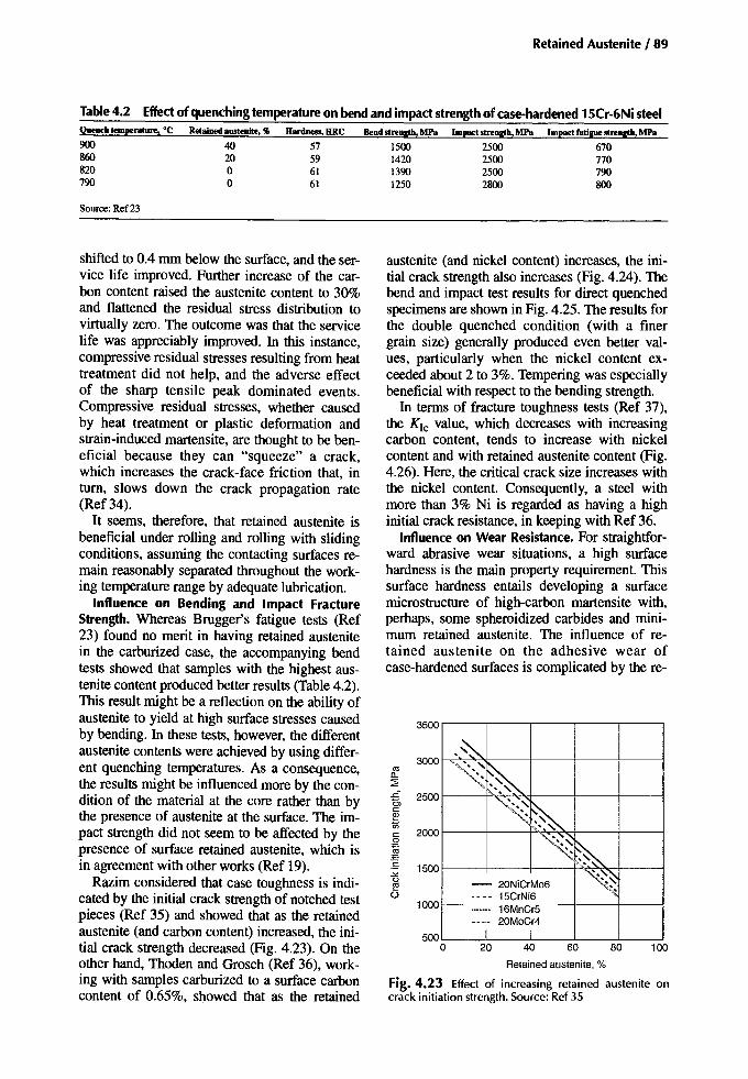
Retained Austenite /89
Table4.2 Effectof quenching temperature on bend and impact strength of case·hardened 15Cr-6Ni steelQueD<h temperature, ·C Bend strength, MPa Impact strength, MPa Impact fatigue strength, MPa
900860820790
4020oo
57596161
1500142013901250
2500250025002800
670770790800
Source: Ref23
Retainedaustenite, %
Fig. 4.23 Effect of increasing retained austenite oncrack initiation strength. Source: Ref 35
austenite (and nickel content) increases, the initial crack strength also increases (Fig. 4.24). Thebend and impact test results for direct quenchedspecimens are shown in Fig. 4.25. The results forthe double quenched condition (with a finergrain size) generally produced even better values, particularly when the nickel content exceeded about 2 to 3%. Tempering was especiallybeneficial with respect to the bending strength.
In terms of fracture toughness tests (Ref 37),the KIc value, which decreases with increasingcarbon content, tends to increase with nickelcontent and with retained austenite content (Fig.4.26). Here, the critical crack size increases withthe nickel content. Consequently, a steel withmore than 3% Ni is regarded as having a highinitial crack resistance, in keeping with Ref 36.
Influence on Wear Resistance. For straightforward abrasive wear situations, a high surfacehardness is the main property requirement. Thissurface hardness entails developing a surfacemicrostructure of high-carbon martensite with,perhaps, some spheroidized carbides and minimum retained austenite. The influence of retained austenite on the adhesive wear ofcase-hardened surfaces is complicated by the re-
10080604020
._~
.~
~~~~~
- 20NiCrMo6 ~•••• 15CrNi6I- ....... 16MnCr5
- 20MoCr4I I500
o
2000
1000
1500
~ 2500c:etlc:o~:-s-'"
~o
3500
3000
shifted to 0.4 mrn below the surface, and the service life improved. Further increase of the carbon content raised the austenite content to 30%and flattened the residual stress distribution tovirtually zero. The outcome was that the servicelife was appreciably improved. In this instance,compressive residual stresses resulting from heattreatment did not help, and the adverse effectof the sharp tensile peak dominated events.Compressive residual stresses, whether causedby heat treatment or plastic deformation andstrain-induced martensite, are thought to be beneficial because they can "squeeze" a crack,which increases the crack-face friction that, intum, slows down the crack propagation rate(Ref 34).
It seems, therefore, that retained austenite isbeneficial under rolling and rolling with slidingconditions, assuming the contacting surfaces remain reasonably separated throughout the working temperature range by adequate lubrication.
Influence on Bending and Impact FractureStrength. Whereas Brugger's fatigue tests (Ref23) found no merit in having retained austenitein the carburized case, the accompanying bendtests showed that samples with the highest austenite content produced better results (Table 4.2).This result might be a reflection on the ability ofaustenite to yield at high surface stresses causedby bending. In these tests, however, the differentaustenite contents were achieved by using different quenching temperatures. As a consequence,the results might be influenced more by the condition of the material at the core rather than bythe presence of austenite at the surface. The impact strength did not seem to be affected by thepresence of surface retained austenite, which isin agreement with other works (Ref 19).
Razim considered that case toughness is indicated by the initial crack strength of notched testpieces (Ref 35) and showed that as the retainedaustenite (and carbon content) increased, the initial crack strength decreased (Fig. 4.23). On theother hand, Thoden and Grosch (Ref 36), working with samples carburized to a surface carboncontent of 0.65%, showed that as the retained
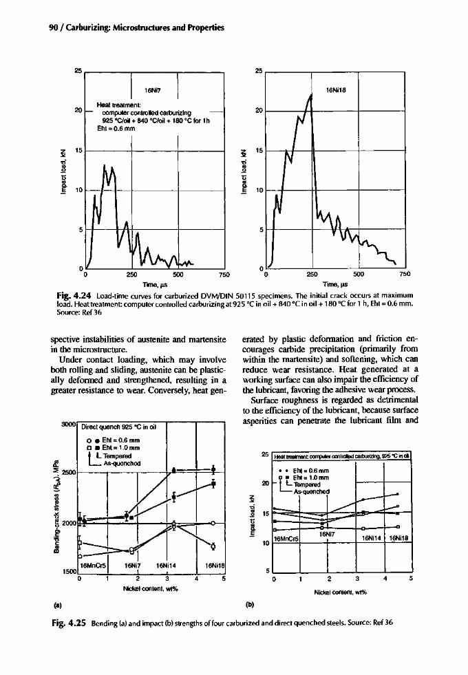
90 / Carburizing: Microstructures and Properties
750500250O~----J..-----'-------'o
5H----+-----\l'-\--,it-+-----1
750500250
51-+--H++--,-----+-----1
25 25
16Ni7 16Ni18
20Heat treatment:
computer controlled carburizing 20
925°C/oil + 840°C/oil + 180 °C for 1hEht= 0.6 mm
~15 z 15
"'"-0 -0
'" Ol.Q .Q
'0 '0Ol Ola. a.§ 10 § 10
Time, I!S Time, its
Fig. 4.24 load-time curves for carburized DVM/DIN 50115 specimens. The initial crack occurs at maximumload. Heattrealment: computer controlled carburizing at925 °C in oil + 840°C in oi I + 180°C for 1 h, Eht = 0.6 mm.Source: Ref 36
5432
Nickelcontent,wt%
Heat treatment computer controlled carburizing, 925 'C inoil
•• Eht= 0.6 mmD • Eht = 1.0 mm
I- L.:: TemperedAs-quenched --~
:~ »> ---"- - -16MnCrs
16Ni716Ni14 16Ni18
5o
25
20
Z
"'".,;Ol 15.Q
UOl0-J;
10
erated by plastic deformation and friction encourages carbide precipitation (primarily fromwithin the martensite) and softening, which canreduce wear resistance. Heat generated at aworking surface can also impair the efficiency ofthe lubricant, favoring the adhesive wear process.
Surface roughness is regarded as detrimentalto the efficiency of the lubricant, because surfaceasperities can penetrate the lubricant film and
5
16Ni18
4
3000 Direct quench 925°C in oil
o • Eht = 0.6 mmo • Eht = 1.0 mmt l TemperedL As-quenched
I"'"~ 2000tiE:=:l:=~~---1-:Q:=:J_-o-l6>c:'6c:OlIII
spective instabilities of austenite and martensitein the microstructure.
Under contact loading, which may involveboth rolling and sliding, austenite can be plastically deformed and strengthened, resulting in agreater resistance to wear. Conversely, heat gen-
(8) (b)
Fig. 4.25 Bending (a) and impact (b) strengths of four carburized and direct quenched steels. Source: Ref 36

RetainedAustenite/91
Table 4.3 Effect of retainedausteniteon the scuffing tendencyofsteelSteel Retained austenite, % Ratl!ll!(a) AGMA2001-C95welding factor, Xw
Stainlesssteel 100 0.32Case-hardenednickel steel >20 0.80Through-hardenedsteel and -20 1.00
case-hardenedchromiumsteelCase-hardenednickelor chromiumsteel <20 1.20
0.450.85 (>30%1r)
1.00(20-30% 1r)
1.15
(a) The higher the rating is, thegreater thescuffingresistancewill be. Source:Ref 38
make contact with similar asperities on the mating surface. The removal of surface asperitiescaused by wear or deformation (probably assisted by the presence of retained austenite),therefore, is considered to be a favorable if notcrucial happening. It redistributes the load andreduces the frictional effects, provided reasonable lubrication is maintained. Further, with thesurface asperities removed, the local contactpressure peaks within the mating surfaces arealso removed as well as the risk of microflaking.There are instances, however, where highly polished surfaces can be difficult to lubricate, and aloss of lubricant in such circumstances couldlead to adhesive wear.
In their approach to predicting the scuffingtendencies of gears, Niemann and Seitzinger(Ref 38) introduce an Xw factor to account forthe potential adverse influence of austenite(Table 4.3). However, the low Xw factor givento stainless steel and attributed to 100% austenite may, in fact, be caused by the nickel content and the absence of carbide precipitates, asshown in Fig. 4.27 (Ref 39). Roberts (Ref 40)points out that both the nickel and the chromium austenitic stainless steels are notoriouslydifficult to lubricate. Roberts (Ref 40) goes onto assert that there is no direct relationship be-
tween scuffing resistance and retained austenitecontent.
Grew and Cameron (Ref 41) suggest that austenite has a lower affinity than martensite for thesurface-active compounds contained in lubricating oils; therefore, it will be more difficult to lubricate. In their tests, which relate the coefficientof friction to the frictional temperature, a carburized and hardened 4%Ni-Cr-Mo steel with 5%retained austenite remained fairly stable,whereas with 25% austenite some instability occurred at 150°C. Following a 180°C temper, theinstability of the surface originally containing25% austenite did not occur until a 180°C friction temperature was reached (Fig. 4.28). Theobserved instabilities relate to the addition ofsurface active compounds, and yet, coincidenceor not, the observed instabilities seem to relate tothe already known thermal instability of austenite. The second stage of tempering commences atabout 150°C, and for an already tempered surface, the second stage of tempering recommences at temperatures above the original tempering temperature. As a reminder, the secondstage of tempering involves the transformation ofretained austenite to bainite (ferrite with carbideprecipitates).
10
(0)
(90)
4
OL-__L-__L-__L-__.&:-_~
o
o -3V:P1O NiCJ-1V2% Nie Low Ni
301----+----+----P-o;;;;:::----jt.;~::iE
<>.z:20I__----+-------'==-......,~--I__----"'--..L_'I
40..------,-----,------,.------,
Alloyingelement content, at.%
Fig. 4.27 Effect of alloy content in Fe-' %C materialson the critical temperature ofa mineral oil. Data in parentheses indicate percentage retained austenite content.Source: Ref 39
1.00.90.80.7
10 '--__--'- ....1- '--__-1
0.6
Carbon, %
Fig. 4.26 Effect of carbon and nickel contents on fracture toughness. Source: Ref 37
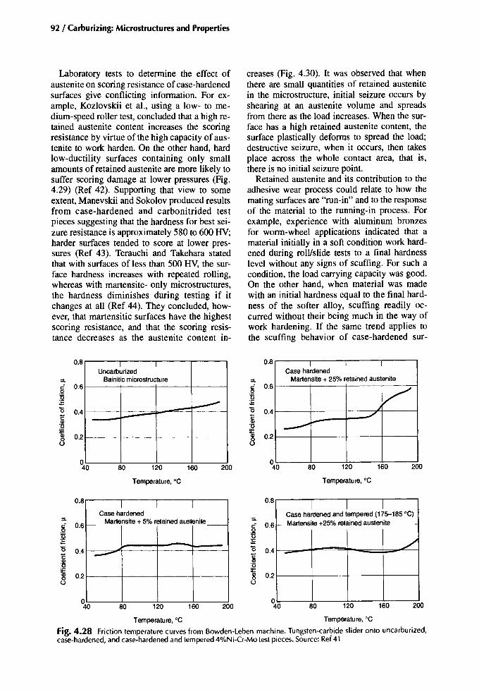
92 / Carburizing: Microstructures and Properties
Laboratory tests to determine the effect ofaustenite on scoring resistance of case-hardenedsurfaces give conflicting information. For example, Kozlovskii et al., using a low- to medium-speed roller test, concluded that a high retained austenite content increases the scoringresistance by virtue of the high capacity of austenite to work harden. On the other hand, hardlow-ductility surfaces containing only smallamounts of retained austenite are more likely tosuffer scoring damage at lower pressures (Fig.4.29) (Ref 42). Supporting that view to someextent, Manevskii and Sokolov produced resultsfrom case-hardened and carbonitrided testpieces suggesting that the hardness for best seizure resistance is approximately 580 to 600 HV;harder surfaces tended to score at lower pressures (Ref 43). Terauchi and Takehara statedthat with surfaces of less than 500 HV, the surface hardness increases with repeated rolling,whereas with martensite- only microstructures,the hardness diminishes during testing if itchanges at all (Ref 44). They concluded, however, that martensitic surfaces have the highestscoring resistance, and that the scoring resistance decreases as the austenite content in-
creases (Fig. 4.30). It was observed that whenthere are small quantities of retained austenitein the microstructure, initial seizure occurs byshearing at an austenite volume and spreadsfrom there as the load increases. When the surface has a high retained austenite content, thesurface plastically deforms to spread the load;destructive seizure, when it occurs, then takesplace across the whole contact area, that is,there is no initial seizure point.
Retained austenite and its contribution to theadhesive wear process could relate to how themating surfaces are "run-in" and to the responseof the material to the running-in process. Forexample, experience with aluminum bronzesfor worm-wheel applications indicated that amaterial initially in a soft condition work hardened during roll/slide tests to a final hardnesslevel without any signs of scuffing. For such acondition, the load carrying capacity was good.On the other hand, when material was madewith an initial hardness equal to the final hardness of the softer alloy, scuffing readily occurred without their being much in the way ofwork hardening. If the same trend applies tothe scuffing behavior of case-hardened sur-
0.8uncarb~riZed
I
:::L Bainitic microstructurec: 0.6.2
~15 0.4i:Q)'0IEQ) 0.20o
0.8
:::Lc: 0.6oU:s"0 0.4i:Q)
:2~ 0.2
I I ICase hardened
Martensite+ 25% retained austenite
V./
-----+-
80 120
Temperature, °C
160 200 80 120
Temperature,oC
160 200
0.8
:::Lc: 0.6
~"0 0.4i:Q)'0
~ 0.2
I I ICase hardened
I--- Martensite+ 5% retainedaustenite_
--0.8
:::Lc: 0.6oU:E(5 0.4i:.!!!o
~ 0.2
I I ICase hardened and tempered (175-185 0C)
_ Martensite+25% retainedaustenite
../-
80 120 160 200 80 120 160 200
Temperature, °C Temperature, °C
Fig. 4.28 Friction temperature curves from Bowden-Leben machine. Tungsten-carbide slider onto uncarburized,case-hardened, and case-hardened and tempered 4%Ni-Cr-Mo test pieces. Source: Ref 41

Retained Austenite / 93
faces, then just sufficient retained austenite toassist the running-in process would seem to bein order. The question then is, what is "just sufficient"?
Control of Retained Austenite
The retained austenite content at the surface ofa carburized steel is influenced by the alloy content of the steel, the surface carbon content, andthe quenching temperature, all of which determine the Ms. The temperature of the quenchantalso contributes to the as-quenched retained austenite content. Primary control, therefore, mustbe by manipulation of these variables.
Considerations Regarding Properties. Whereascertain standards quote maximum retained austenite contents, there is some latitude for themanufacturer to adjust the amount within thoselimits (i.e., 0 to 35% American Gear Manufacturers Association). Before deciding on the surface carbon content and the quenching temperature for a chosen steel grade, it is necessary toestablish what level of retained austenite can betolerated. Making these decisions requires someknowledge of how the component functions andhow it will be loaded in service. In dealing withgears, each type of loading, or action, must beconsidered. For example, if the safety factor fortooth bending is small compared to surface pit-
ting, the austenite content should be kept to aminimum (preferably without refrigeration). Ifthe converse applies, then a retained austenitecontent approaching 35% is more appropriate. Ifoccasional tooth bending overloads are expected,then to deter initial cracking it might be prudentto aim for an austenite content of about 25%. Ifalife of less than I x IQ4 cycles at high loads is required, then much higher austenite contents canbe considered. If, on the other hand, adhesivewear (scoring, scuffing) is the more likely failuremode, then it is necessary to lower the austenitecontent.
Heat Treating. It should be apparent that nosingle value for retained austenite content willsatisfy all requirements of a gear tooth. Theforegoing discussion is very nice in theory, butin practical terms it is not altogether realistic. Ifa designer had the time to determine the bestaustenite content for a particular gear, could theheat treater comply? In commercial heat treatment, the best an operator can do, given a steelgrade and quenching method, is adjust the surface carbon content to obtain a retained austenite content within the recommendation of thestandard.
Post case-hardening refrigeration is an effective means of reducing retained austenite, but itcan have drawbacks in its influence on materialproperties. Therefore, carburizing and hardeningprocesses should avoid the formation of excessive amounts of austenite in the first place. If a
~ 1500 --0co!2Gl:; r--Na; 1000en
500
M1,10.7% RAM2, 18.1%RA
_ M3, 49.2% RA
2500~-----'
M1 M2 M3
Specimen
Fig. 4.30 Relation between seizure load and percentage of retained austenite (RA). Source: Ref 44
2000
I I I ICJ Austenite at surface
c- CJ Austenite at 0.15 mm
r-- - - f---
- f-
- -
- -
- -
f--- -
- ,...- f--- -
E~ 800.><
ff 700c!!l'".~ 600
Olc'8 500en
Retained austenite, %
Fig. 4.29 Effectof retained austenite on scoring resistance. Source: Ref 42
200o 10 20 30 40 50 60 70
300
1000
900
1100
400

94 / Carburizing: Microstructures and Properties
subzero treatment is unavoidable, then a shallowrather than a deep freeze should be considered,as too should both prior and post tempering operations. The subject of refrigeration is coveredin more depth in Chapter 7, "PostcarburizingThermal Treatments."
Surface Working. The properties of surfacescontaining retained austenite can be favorablymodified by mechanical methods that induceplastic deformation, such as shot peening orsurface rolling. Retained austenite, being relatively soft, is work hardened by these processes with the added benefit that the surfaceresidual stresses are made more compressive.It is important, however, that the balancingtensile residual stresses do not peak just beneath the worked layer. Correctly executedsurface working is capable of not only overcoming any adverse effects 'of retained austenite but also of raising the fatigue strengthof the part to well above that obtained solelyby thermal means.
Summary
Retained austenite is more or less unavoidablein quenched carburized steels. The amount of retained austenite is determined by the carbon content, quenching, and quenchant temperatures.For most applications some retained austenite isacceptable; if in excess, it can lead to grindingproblems.
• Preprocess considerations: It is normal to select steel for a component based on size andeventual duty. Therefore, the possibility ofproducing high retained austenite contents atthe surface can be anticipated.
• In-process considerations: Carbon-potentialcontrol and quenching methods are means ofcontrolling the austenite content. Generally,lean grades of steel are direct quenched, andthe more highly alloyed grades are reheatquenched.
• Postprocess considerations: If retained austenite is unacceptably high, consider requenchingfrom a lower temperature (watch distortion aspect). Alternatively, use shallow refrigeration ifthe adverse effects of the process can be tolerated.
• Effect on properties: Retained austenite reduces hardness, abrasive wear resistance, andbending-fatigue strength, but it is thought to
benefit contact fatigue. Conflicting data existregarding adhesive wear. In all cases, the austenite and accompanying martensite shouldbe fine and evenly distributed.
• Standards: For the lower quality grade neitherANSI!AGMA nor ISO provides a specification. For the middle and the highest grades,ANSI!AGMA quotes 30% maximum retainedaustenite, whereas ISO calls for 25% maximum.
REFERENCES
I. A Rose and H.P. Hougardy, TransformationCharacteristics and Hardenability of Carburising Steels, Transformation and Hardenability in Steels, Climax Molybdenum Co. ofMichigan, 1967, p 155-167
2. E.C. Rollason, "Fundamental Aspects of Molybdenum on Transformationof Steel,"ClimaxMolybdenum Co. of Europe Ltd.
3. R Priestner and S.G. Glover, StabilisationEffect in a High Carbon Nickel Steel, Physical Properties of Martensite and Bainite,Special report 93, The Iron and Steel Institute, 1965, p 38-42
4. W.S. Owen, Theory of Heat Treatment, HeatTreatment ofMetals, Hatte Books Ltd., 1963,P 1-28
5. AG. Haynes, Interrelation of Isothermal andContinuous-Cooling Heat Treatments ofLow-Alloy Steels and Their Practical Significance, Heat Treatment of Metals, Special report 95, The Iron and Steel Institute, 1966, p13-23
6. D.P. Koistinen and RE. Marburger, A General Equation Prescribing the Extent of theAustenite-Martensite Transformation in PureIron-Carbon Alloys and Plain Carbon Steels,Acta Metall., Vol7, 1959, p 59-60
7. c.Y. Kung and J.J. Rayment, An Examination of the Validity of Existing EmpiricalFormulae for the Calculation of M, Temperature, Metall. Trans. A, Vol 13, Feb 1982,p 328-331
8. E. Szpunar and 1. Beilanik, Influence of Retained Austenite on Propagation of FatigueCracks in Carburised Cases of Toothed Elements, Heat Treatment '84, The Metals Society, p 39.1-39.9
9. L.A Vasil'ev, Retained Austenite and Hardness of the Carburised Case on Steel18Kh2N4VA after Quenching in 'IWo Different Media, Met. Sci. Heat Treat., Vol 14

(No.2), Feb 1972,p 58-5910.O.A. Ankaraand DRE West, Investigation of
Transformation Plasticity during MartensiteFormation in a Medium Alloy Steel, PhysicalProperties of Martensite and Bainite, Specialreport 93, The Iron and Steel Institute, 1965,p 183-192
11.K. Bungardt, E. Kunze, and H. Brandis,Betrachtungen zur Direkthartung vonEinsatzstahlen, DEW-Technische Berichte,Vol5 (No.1), 1965,P 1-12
12.RW. Neu and S. Huseyin, Low TemperatureCreep of a Carburised Steel,Metall. Trans. A,Vol 23, Sept 1992,p 2619-2624
13.RH. Richman and RW. Landgraf, Some Effectsof RetainedAusteniteon the FatigueResistanceof Carburized Steel,Metall. Trans. A,Vol 6, May 1975,p 955-964
14.R.I. Johnson, 'The Role of Nickel in Carburising Steels," Publication A 1205, International NickelCompany, Inc.
15.X. Yen, D.Zhu,and D. Shi,The StressInducedPhase Transformation of Carburising andCarbonitrided Layers and Their Contact Fatigue Behaviour, Heat Treat. Met. (China), Vol1, 1984,P 31-37
16.l Franklin, P.Hill, and C. Allen,The EffectofHeat Treatmenton RetainedAustenite in a 1%Carbon-Chrornium Bearing Steel, Heat Treat.Met; Vol 2, 1979,p 46-50
17.D.P. Koistinen, The Distribution of ResidualStressesin Carburised Casesand Their Origin,Trans. ASM, Vol50, 1958,P 227-241
18. L. Salonen,The Residual Stressesin the CarburisedLayersin theCaseof an Unalloyed anda Mo-Cr Alloyed Case-Hardened Steel afterVarious Heat Treatments, Acta Polytech.Scand., Vol 109, 1972,P 7-26
19.D.E. Diesburg, C. Kim, and W. Fairhurst,Microstructural and ResidualStressEffectsonthe Fracture of Case-Hardened Steels, paper23, Heat Treatment '81 (University of Aston),The Metals Society, Sept 1981
20.M.M. Shea, Residual Stress and Microstructurein Quenchedand Tempered and HotOil Quenched Carburised Gears, J. HeatTreat., Vol 1 (No.4), Dec 1980, P 29-36
21.H. Wiegand and G. Tolasch, The CombinedEffect of Individual Factors on Raising theAlternating Bending Fatigue Strength ofCase-Hardened Test Pieces, HiirtereiTechnische Mitteilungen (HISI6081), Vol 22,Oct 1967,P 213-220
RetainedAustenite/ 95
22.C. Razim, Influenceof ResidualAusteniteonthe StrengthProperties of Case-Hardened TestPieces during Fatiguing, Harterei-TechnischeMitteilungen (BISI 6448), Vol23, April 1968,P 1-8
23. H. Brugger, Werkstoff und Wiirmebehandlungseinflusse auf die Zahnfujitragfahigkeit,VDI-Berichte, (No. 195), 1973,P 135-144
24.lL. Pacheco and G. Krauss, Microstructureand High BendingFatigueStrengthof CarburisedSteel,J Heat Treat., Vol7 (No.2), 1989,p77-86
25.M.A. Zaconne, lB. Kelley, and G. Krauss,Strain Hardening and Fatigue of SimulatedCaseMicrostructures in Carburised Steel,Corf.Proc. Processing and Performance (Lakewood,CO), ASM International, July 1989
26. G.Y. Kozyrev and G.V. Toporov, Effectof Retained Austenite on the Impact-FatigueStrengthof Steel, Metal Sci. Heat Treat., Vol15 (No. 12),Dec 1973,P 1064-1066
27.M.A.Panhansand RA Fournelle, HighCycleFatigueResistance of AISI E 9310 CarburisedSteel with Two Different Levels of RetainedAustenite and SurfaceResidualStress,J HeatTreat., Vol 2 (No.1), 1981,P 54-61
28.C. Razim, Effects of Residual Austenite andRecticular Carbideson the Tendency to Pittingof Case Hardened Steels, thesis, Techn.Hochschule Stuttgart, 1967
29.M.A.Balterand M.L. Throvskii, Resistance ofCase-Hardened Steel to Contact Fatigue,Met. Sci. Heat Treat., (No.3), March 1966,p 177-180
30.A Diament, R El Haik, R Lafont, and RWyss, "Surface Fatigue Behaviour of theCarbonitrided and Case-Hardened Layers inRelation to the Distribution of the ResidualStresses and the Modifications of the CrystalLattice Occurring during Fatigue" (BISI12455), paper presented at 25th Colloque Int.(Caen, France), 29-31 May 1974, International Federation for the Heat Treatment ofMaterials, 1974
31.B.B. Vinokur, S.E. Kondratyuk, L.I.Markovskaya, RA Khrunik, AA Gurmaza,and Y.B. Vainerman, Effect of RetainedAusteniteon the Contact FatigueStrengthof Carburised Steel, Met. Sci. Heat Treat., (No. 11),Nov 1978,P 47-49
32.B. Vinokur, The Composition of the SolidSolution Structure and Contact Fatigue of theCase-Hardened Layer, Metall. Trans. A, Vol24, May 1993,p 1163-1168

96 / Carburizing: Microstructures and Properties
33. P. Barczy and J. Takacs, Endurance Improvements of Planet Gear Pins by Heat Treatment,paper24, Heat Treatment '84, The Metals Society,1984
34. G.T. Hahn, Y. Bhargava, C.A Rubin, and X.Leng, Analysis of the Effects of HardenedLayers on Rolling and Sliding Contact Performance, Conf. Proc. Processing and Performance (Lakewood, CO), ASM International,1989
35. C. Razim, Survey of Basic Facts of DesigningCase Hardened Components, unpublished private print, 1980
36. B. Thoden and 1. Grosch, Crack Resistance ofCarburised Steel under Bend Stress, Conj Proc.ProcessingandPerformance (Lakewood, CO),ASM International, 1983
37. V.K. Sharma, G.H. Walter, and D.H. Breen,The Effect of Alloying Elements on CaseToughness of Automotive Gear Steels, HeatTreatment '87, The Metals Society, 1987
38. G. Niemann and A Seitzinger, ''Calculation ofScoring Resistance for Spur and HelicalGears," ISO 6336, International Standards Organization, 1996
39. R.M. Matveevsky, Y.M. Sinaisky, and IABuyanovsky, Contributions to the Influence ofRetained Austenite Content in Steels on theTemperature Stability of Boundary LubricantLayers in Friction, 1 Lubr. Technol. (Trans.ASME), July 1975, P 512-515
40. AG. Roberts, discussion appended to Ref39
4 W. Grew and A. Cameron, Role of Austen-1. ite and Mineral Oil in Lubricant Failure,
Nature, Vol 217 (No. 5127), 3 Feb 1968,p 481-482
42. I.I. Kozlovskii, S.E. Manevskii, and I.I.Sokolov, Effect of Retained Austenite onthe Resistance to Scoring of Steel 20Kh2N4A,Met. Sci. Heat Treat., (No.1), 1978, P 7{}-80
43. S.E. Manevskii and I.I. Sokolov, Resistance toSeizing of Carburised and Carbon NitridedSteels, Metalloved. Term. Obrab.Met., (No.4),April 1977, P 66-68
44. 1. Terauchi and 1.1. Takehara, On the Effect ofMetal Structure on Scoring Limit, Bull. Jpn.Soc. Meek Eng., Vol21 (No. 152), Feb 1978, p324-332
SELECTED REFERENCES
• J. Grosch and O. Schwarz, Retained Austenite and Residual Stress Distribution in Deep
Cooled Carburized Microstructures, Conj:1995 Carburizlng and Nitriding With Atmospheres, 6-8 Dec 1995, (Cleveland, Ohio),ASM International, 1995 p 71-76
• A Inada, H. Yaguchi, and T. Inoue, Effects ofRetained Austenite on the Fatigue Propertiesof Carburized Steels, Kobelco Technol. Rev.,Vo117, April 1994, p 49-51
• G. Krauss, Advanced Performance of SteelSurfaces Modified by Carburizing, Conj:Heat & Surface '92, 17-20 Nov 1992 (Kyoto,Japan), Japan Technical Information Service,1992, p 7-12
• G. Krauss, Microstructures and Properties ofCarburized Steels, Heat Treating, Vol 4,ASM Handbook, ASM International, 1991,p 363-375
• F. Li and C. Li, The Influences of Heat Treatment After Carburizing and Retained Austenite in the Carburized Layer on the Strengthand Toughness of Steel, Trans. Met. HeatTreat. (China), Vol 6 (No.2), Dec 1985,p 59-68
• J.D. Makinson, WN. Weins, and R.I. deAngelis, The Substructure of Austenite andMartensite Through a Carburized Surface,Conj: Advances in X-Ray Analysis, Vol 34,30 July to 3 Aug 1990 (Steamboat Springs,Colorado), Plenum Publishing Corporation,p 483-491
• D.L. Milam, Effect of Interrupted Cooling onRetention of Austenite and Development ofCase Hardness in a Carburizing Process,Conj: 1995 Carburizing and Nitriding WithAtmospheres, 6-8 Dec 1995 (Cleveland,Ohio), ASM International, p 111-116
• R.W Neu and H. Sehitoglu, Transformationof Retained Austenite in Carburized 4320Steel, Metall. Trans. A, Vol 22 (No.7), July1991, p 1491-1500
• M. Przylecka, M. Kulka, and W Gestwa, Carburizing and Carbonitriding Bearing Steel(LHI5-521oo), Conj: Heat Treating: Equipment and Processes, 18-20 April 1994(Schaumburg, Illinois), ASM International,1994, p 233-238
• E. Shao, C. Wang, and Ci-S. Zheng, Improving Rolling Contact Fatigue Strength forCarburizing Gears With Retained Austeniteand Carbide in Their Case and Its Application, Trans. Met. Heat Treat. (China), Vol 10(No.1), June 1989, p 31-43

• J. Siepak, Effect of Retained Austenite inCarburized Layers on Rolling Wear, NeueRuNe, Vol 29 (No. 12), Dec 1984, p 452-455
• B.B. Vinokur and A.L. Geller, The Effect ofRetained Austenite on Contact Fatigue inCr-Ni-W Carburized Steel, J. Met., Vol 49
Retained Austenite I 97
(No.9), Sept 1997, P 69-71• D. Zhu, F.-X. Wang, Q.-G. Cai, M.-X. Zheng,
and Y.Q. Cheng, Effect of Retained Austeniteon Rolling Element Fatigue and Its Mechanism, Wear, Vol 105 (No.3), 1 Oct 1985,p223-234

Chapter 5
Influential Microstructural Features
Microstructural features observed withincase-hardened steels include grain size,microcracking, microsegregation, and nonmetallic inclusions. Although these microstructuralconstituents are not considered in the same detailas those presented in the first four chapters, theirsignificant influence on properties justifies theirreview.
Grain Size
For optimal properties, it is essential that thegrain size of a carburized and hardened component is both uniform and fine. Generally, thestarting point is a grain-refined steel having anASTM grain size from No.5 to 8, though subsequent mechanical and thermal processing canchange the final microstructure to be either morecoarse or fine.
At one time, grain size control was very muchin the hands of the heat treater who, suppliedwith coarse-grained steels, employed doublequenching treatments to ensure that both case
and core of the carburized item were refined.However, the advent of grain refinement by alloying obviated the need for carburized components to be double quenched. Now, the majorityof heat treaters either employ direct quenching orsingle reheat quenching to harden their products.Figure 5.1, coupled with Table 5.1, illustratesdifferent thermal cycles used to effect hardeningand generally ensure a fine-grained product, provided the carburizing temperature for all programs except D is not excessive. Much of theflexibility for process cycles must be attributedto the availability of grain-refined steels.
In addition to the process cycles shown inFig. 5.1, some cycles include a subcritical annealing, or a high-temperature tempering operation, between the carburizing and hardeningstages. By slow cooling from the carburizing temperature then annealing or tempering from 600 to650°C, the part is rendered suitable for any intermediate machining needed. Another use of thehigh-temperature tempering involves a version ofthe double quenching program (D in Fig. 5.1).The first quenching operation is into a medium
FEDCBA_ ~rb~iz~g ~m~ra~re_
r ~------C'!""-@""-'l!£<'!'
l!! I C~~ra.!!.g~f~se
~8E
{!J.
Carboncontent,percent TIme---_
Fig. 5.1 Alternative heat treatment cycles for hardening carburized components. Seealso Table 5.1. Source: Ref 1
Carburizing: Microstructures and Properties Copyright © 1999 ASM International® Geoffrey Parrish, p 99-133 All rights reserved. DOI: 10.1361/cmap1999p099 www.asminternational.org

100 / Carburizing: Microstructures and Properties
Table5.1 Caseand core characteristics resultingfrom the variousheat treatments shown in Fig. 5.1Treatment Case Core
A: Best adaptedto fine-grainedsteels Refined;excess carbide not dissolved;distortion minimized
B: Bestadaptedto fine-grainedsteels Slightly coarsened; some solution ofexcess carbide
C: Bestadaptedto fine-grainedsteels Somewhatcoarsened; solution of excesscarbide favored;austeniteretentionpromoted in highly alloyed steels
D: Besttreatmentforcoarse-grained steels Refined; solution of excesscarbide favored;austeniteretention minimized
E:Suitablefor fine-grainedsteelsonly Unrefined with excesscarbide dissolved;austenite retained; distortion minimized
F: Suitablefor fine-grainedsteelsonly Unrefined;excess carbide avoidedif combinedwith diffusion treatment; austenite retentionreduced; distortion minimized
Unrefined; soft and machinable
Partially refined; stronger and tougher than A
Refined;maximumcore strengthandhardness;better combination of strength and ductilitythanB
Refined; soft and machinable; high degreeof toughness and resistance to impact
Unrefinedbut hardened
Unrefinedbut hardened
Source: Ref I
• Boundary migration, which occurs at all temperatures but affects grain growth only at temperatures above 1100 DC
The first two mechanisms involve the decomposition of old boundaries, whereas the third involvesthe movement of boundaries.
Grain SizeControl. Grain refinement by alloying is accomplished by adding certain elements(e.g., aluminum or vanadium) to the molten steelin the ladle after a thorough deoxidation treatment, usually with silicon. Silicon in adequatequantities, although harmful in terms of internaloxidation during carburizing, is important as adeoxidizer and, therefore, for grain size control(Fig. 5.2). Additions of aluminum and/or vanadium encourage the formation of compounds(e.g., AIN or V4C3) that, because of their extreme fineness and relative stability, are able tomechanically restrain grain boundary movement during subsequent austenitizing treatments. Of the grain refining agents, AIN ismore important for fine-grain stability. The effect of grain refining treatments is limited, because above a certain temperature within theaustenite range, the precipitated compounds coalesce and then dissolve. Consequently, theycan no longer prevent grain boundary movement. However, the grain coarsening temperature is further increased by adding both aluminum and titanium. This addition is importantwhen any high-temperature carburizing processis being used, if indeed grain coarsening is aproblem. The efficiency of aluminum to inhibitaustenite grain growth is illustrated in Fig. 5.3,which compares an untreated steel with an aluminum treated steel. Figure 5.3(a) shows thatthe untreated steel coarsens progressively as thetemperature increases, whereas the treated steel
21.4%coarsJ- 11.1% coarse. IeRne-grainedgrainedcasts ! grainedcasts ~s
x oarse-grained_
I casts
I-I •I.I ~• • I -- •
t •-- x'wr-~1..... -
• x rI • •x
5 .. I· •• x x x •l
o 66.7% coarse. I • 18.2%coarse-grained castst I grainedcastj
5I
0.15 0.20 0.25 0.30 0.35
Carbon. %
Fi~. 5.2 Effect of carbon and silicon on grain size controTof 665M17 steel made by basic electric-arc processwith aluminum addition of 16 oz/ton. Source: Ref 4
0.1
0.1
0.0
0.25
0.30
0.35
"if.C~0.20
Ci5
• The resorption of grains, which occurs at 50to 100 DC above the AC3
• The formation of new boundaries and grainsbetween 250 and 300 DC above the AC3
held at a temperature not too far below the ACtfrom which the workpieces are then reheated forthe second quench. The aim is to ensure grain refinement (Ref 2) and reduce distortion and therisk of cracking.
Evaluation ofGrain Size
Grain Growth. Vinograd et al. (Ref 3), whostudied the behavior of twelve different steelsheated from 850 to 1250 °C, concluded thatgrain growth takes place by three different mechanisms:
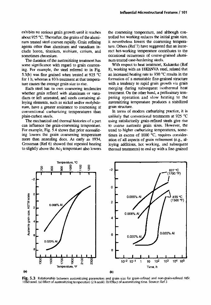
Influential Microstructural Features / 101
exhibits no serious grain growth until it reachesabout 925 "C. Thereafter, the grains of the aluminum treated steel coarsen rapidly. Grain refiningagents other than aluminum and vanadium include boron, titanium, niobium, cerium, andsometimes chromium.
The duration of the austenitizing treatment hassome significance with regard to grain coarsening. For example, the steel referred to in Fig.5.3(b) was fine grained when treated at 925 "Cfor 1 h, whereas a 10 h treatment at that temperature causes the average grain size to rise.
Each steel has its own coarsening tendencieswhether grain refined with aluminum or vanadium or left untreated, and steels containing alloying elements, such as nickel and/or molybdenum, have a greater resistance to coarsening atconventional carburizing temperatures thanplain-carbon steels.
The mechanical and thermal histories of a partcan influence the grain-coarsening temperature.For example, Fig. 5.4 shows that prior normalizing lowers the grain coarsening temperaturemore than annealing does. As early as 1934,Grossman (Ref 6) showed that repeated heatingto slightly above the AC3 temperature also lowers
the coarsening temperature, and although controlled hot working reduces the initial grain size,it nevertheless lowers the coarsening temperature. Others (Ref 7) have suggested that an incorrect hot-working temperature contributes to theoccasional occurrence of coarse-grained aluminum treated case-hardening steels.
With respect to heat treatment, Kukareko (Ref8), working with an 18KhNVA steel, related thatan increased heating rate to 930 "C results in theformation of a metastable fine-grained structurewith a tendency to rapid grain growth via grainmerging during subsequent isothermal heattreatment. On the other hand, a preliminary tempering operation and slow heating to theaustenitizing temperature produces a stabilizedgrain structure.
In terms of modem carburizing practice, it isunlikely that conventional treatments at 925 "Cusing satisfactorily grain-refined steels give riseto coarse austenite grain sizes. However, thetrend to higher carburizing temperatures, sometimes in excess of 1000 "C, requires consideration of all aspects of grain refinement (e.g., alloying additions, hot working, and subsequentthermal treatments) to end up with a fine-grained
10 102
Time. h
10-2 10-1
8
-2
0
Gl
~:::ii 2l-f/)
2-cl!i"iiic: 4.~
Cl 4s'c
*~ 6
Temperature. of
Temperature. °C
8 8
(8) (b)
Fig. 5.3 Relationship between austenitizing parameters and grain size for grain-refined and non-grain-refined AISI1060 steel. (a) Effect of austenitizing temperature (2 h soak). (b) Effect of austenitizing time. Source: Ref 5
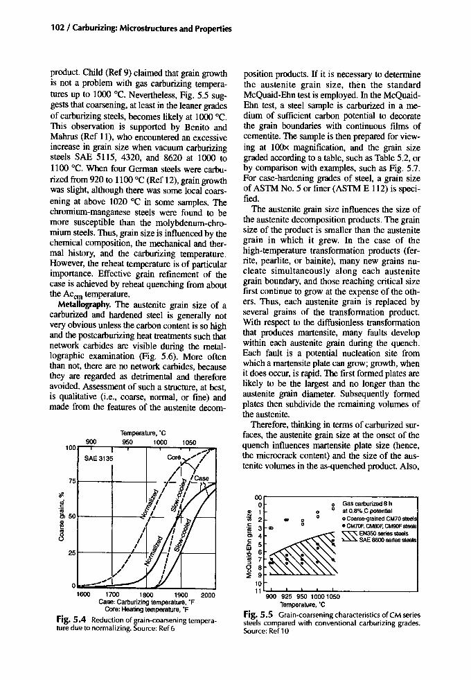
102 / Carburizing: Microstructures and Properties
oor----------------.o 0 Gas carnurized 8 h.g} 1 0 0 at 0.8%C potential<1) 2 .. 0 0 0 Coarse-grained CM70steels.§ 3 CD 0 • CM70F, CMBOF, CM90F steels
Cl 4~~ EN350series steels~ 5 ••.•• ~ SAE8600series steels:2 6~ 7CJ 8~ 9
1011'-:-1":"""":~~~.L--L--------1
900 925 950 1000 1050Temperature, 'C
Fig. 5.5 Grain-coarsening characteristics of eM seriessteels compared with conventional carburizing grades.Source: Ref 10
position products. If it is riecessary to determinethe austenite grain size, then the standardMcQuaid-Ehn test is employed. In the McQuaidEhn test, a steel sample is carburized in a medium of sufficient carbon potential to decoratethe grain boundaries with continuous films ofcementite. The sample is then prepared for viewing at l00x magnification, and the grain sizegraded according to a table, such as Table 5.2, orby comparison with examples, such as Fig. 5.7.For case-hardening grades of steel, a grain sizeof ASTM No.5 or finer (ASTM E 112) is specified.
The austenite grain size influences the size ofthe austenite decomposition products. The grainsize of the product is smaller than the austenitegrain in which it grew. In the case of thehigh-temperature transformation products (ferrite, pearlite, or bainite), many new grains nucleate simultaneously along each austenitegrain boundary, and those reaching critical sizefirst continue to grow at the expense of the others. Thus, each austenite grain is replaced byseveral grains of the transformation product.With respect to the diffusionless transformationthat produces martensite, many faults developwithin each austenite grain during the quench.Each fault is a potential nucleation site fromwhich a martensite plate can grow; growth, whenit does occur, is rapid. The first formed plates arelikely to be the largest and no longer than theaustenite grain diameter. Subsequently formedplates then subdivide the remaining volumes ofthe austenite.
Therefore, thinking in terms of carburized surfaces, the austenite grain size at the onset of thequench influences martensite plate size (hence,the microcrack content) and the size of the austenite volumes in the as-quenched product. Also,
900
,,""o --_....
'#.~·iiia. 50t----+---~
j
751---+----1--
1600 1700 1800 1900 2000Case:Carburizingtemperature, 'F
Core:Healing temperature, 'F
Fig. 5.4 Reduction of grain-coarsening temperature due to normalizing. Source: Ref 6
SAE3135
25t---+--
product. Child (Ref 9) claimed that grain growthis not a problem with gas carburizing temperatures up to 1000 °C. Nevertheless, Fig. 5.5 suggests that coarsening, at least in the leaner gradesof carburizing steels, becomes likely at 1000 "C.This observation is supported by Benito andMahrus (Ref 11), who encountered an excessiveincrease in grain size when vacuum carburizingsteels SAE 5115, 4320, and 8620 at 1000 to1100 °C. When four German steels were carburized from 920 to 1100 °C (Ref 12), grain growthwas slight, although there was some local coarsening at above 1020 °C in some samples. Thechromium-manganese steels were found to bemore susceptible than the molybdenum-chromium steels. Thus, grain size is influenced by thechemical composition, the mechanical and thermal history, and the carburizing temperature.However, the reheat temperature is of particularimportance. Effective grain refinement of thecase is achieved by reheat quenching from aboutthe Accrn temperature.
Metallography. The austenite grain size of acarburized and hardened steel is generally notvery obvious unless the carbon content is so highand the postcarburizing heat treatments such thatnetwork carbides are visible during the metallographic examination (Fig. 5.6). More oftenthan not, there are no network carbides, becausethey are regarded as detrimental and thereforeavoided. Assessment of such a structure, at best,is qualitative (i.e., coarse, normal, or fine) andmade from the features of the austenite decom-

Influential Microstructural Features / 103
Fig. 5.6 Prior austenite grain boundaries. (a) Coarse-grained SAE 1015 carbonsteel, carburized. 100x. (bl Fine-grained SAE 4615 nickel-molybdenum steel, carburized.l00x
grain size affects the frequency and depth of internal oxidation and, therefore, the grain size ofany high-temperature transformation products(HTTP) associated with it.
The austenitic grain size data for incomingmaterials may be provided by the steel supplieror determined by the customer as part of routineacceptance testing. Unfortunately, grain size determinations made on a small diameter forgedtest bar may not truly reflect on those of the partsthat the test bar represents. For example, theamount of hot working can be different, as toothe heating and cooling rates during any simulated carburizing treatments. Dietrich et al. (Ref13) warned how normalizing prior to grain sizetesting could produce a false result and that slowheating (3 °Ctmin) to the testing temperature canlower the content of coarse grains. Subcriticalannealing (710 "C) has a similar effect. Even so,
Table5.2 ASTM grainsize
grain size control and assessment by steelmakersare sufficiently adequate to assure the customerthat fine-grained steels are being provided.
The hardenability of a fine-grained steel is lessthan that of a coarse-grained steel having anidentical chemical composition. The same applies to the case hardenability. However, whereasthis distinction is especially meaningful for plaincarbon and very lean-alloy case-hardeninggrades and may lead to problems during processing, it is of less concern for the more alloyedsteels (Ref 14).
Francia (Ref 15), who provides a reminder thathardenability is critical in gear steel selection,makes the point that hardenability should not besought by the use of coarse-grained materials.Apart from having the potential to produce inferior properties, coarse-grained steels distort morethan their fine-grained counterparts.
I I2 23 44 85 166 n7 M8 I~
4.05.68.0
11.316.822.632.045.3
270340480679%1
136019202720
Gram dlamele!«), in.
0.01130.00800.005670.004000.002830.002000.001420.00100
(a) Calculated for cub ical grains allOOx. (b) Average caleulated fora l4-sided solid of maximum ability for close packing. (e) Equ ivalent sphericalgrain.not magnified

104 / Carburizing: Microstructures and Properties
Effed ofGrain Size on Properties
Most properties are modified by changes ofgrain size, and some properties are adversely affected by an increase of grain size. However, information dealing specifically with the effects ofgrain size on the properties of case-hardenedparts is somewhat limited. Therefore, where di-
ASTMNo.7
Fig. 5.7 Comparison of nominal ASTM 6 to 9 grainsize (with calculated grain size numbers of 6.08,7.13,8.03 , and 8.97, respectively). Nital etch, 100x
rect information is absent, other studies (ofnon-case-hardened steels) are referenced to obtain reasonable trends and guidance.
Hardness. Austenitic grain size does notgreatly affect the surface hardness of carburizedand hardened surfaces and only marginally influences the core hardness. For high-carbonmartensite, Kelly and Nutting (Ref 16) considered that grain size has a negligible influence onthe increase of hardness , and other factors, suchas carbon in solid solution within the twinnedmartensite or carbide precipitation, are far moresignificant. However, Zaccone et al. (Ref 17), using steels of varying chromium content and grainsize, showed with direct quenched samples thatfor a given grain size the hardness decreases asthe retained austenite increases. With reheatquenched samples in which both grain size andretained austenite vary, there is a different trend(Fig. 5.8). This trend difference might be attributed to grain size. The reheat quenched sampleswere, as expected, finer grained than their directquenched counterparts.
For low-carbon ferritic steels (i.e., ferrite,ferrite/pearlite, and the quenched and hightemperature tempered microstructures), an approximately linear relationship between hardnessand grain size might beexpected. The results forthree plain-carbon steels in the worked, quenched,and high-temperature tempered condition areshown in Fig. 5.9. The trend is for hardness to increase as grain size decreases. However, over therange of grain sizes typical for case-hardenedsteels, the change in hardness is less than 20 HV.
Tensile Strength Properties. In heat-treatedsteels, the tensile yield strength is influenced bya number of factors including grain size (prioraustenite grain size or as-heat-treated grain size).The yield strength is inversely proportional to thesquare root of the austenite grain size (Ref 16).This is illustrated in Fig. 5.10 for two martensiticsteels where the yield strength increases as thegrain size decreases by about 21 MPa per grainsize (d-I12, mm- I12) change . Other factors thatinfluence yield strength include carbon segregation, precipitates, and the substructure of themartensite (dislocations , internal twinning) .
Schane (Ref 20), employing fine- andcoarse-grained SAE 1040 steels, showed that aninitially coarse-grained steel began to furthercoarsen at a relatively low austenitizing temperature (810 to 840 DC), while an initially finegrained material resisted coarsening until temperatures above about 1000 DC were used. The

Influential Microstructural Features / 105
properties obtained after normalizing at temperatures up to 1093 °C are shown in Fig. 5.11. Interms of ductility, the fine-grained steel was thebetter of the two. The inflections in the curvescoincide with the onset of grain coarsening.
Residual Stresses. Acknowledging that grainsize differences might influence the proportions of the transformation products in a casehardened surface, particularly the plain-carbongrades, then it can be reasoned that the residualstress distribution within the carburized case willbe modified accordingly. Also, coarse-grainedsteels are more prone to distortion (which is a residual stress effect) than fine-grained steels,which could be a reflection on the influence ofgrain size on hardenability.Coarse-grained steelsalso tend to be more prone to cracking andmicrocracking during quenching or grinding;
54o
300
275 ]!~
250 g>il
225 ~':;'
m2OO:geft"!
175 0
3010 20Grainsize (d""1/2), mm-1/2
I I8650:0.5C-1Mn-D.5Ni-D.5Cr-0.25Mo4340:0.4C-D.7Mn-0.8Cr-l.5Ni-0.25MO/,
865jV"V,D/
o .......e
~ '0
~4~9-/
• •. /'
/~/)/;0
0
By = So + 3000d""1/2
, , ,
1200o
2200
£g> 1800
~32.~ 1600
~o 1400~ci
~ 2000::!
260
>:I:<Ii'" 220Q)c"Eto:I:
180
Grain size, ASTMnumber
35 7 9 11 13 15
140
300
Grain size (d""1/2), mm- l12
Fig. 5.9 Variation of hardness with ferrite grain size.Source: Ref 1B
again, macrostresses and microstresses are involved.
Fatigue Strength. The grain size of a steel affects its response to cyclic loading. Macherauch(Ref 21) showed that, for a low-carbon steel,coarse-grained structures are inferior tofine-grained structures when tested under bending fatigue conditions (Fig. 5.12). The same
80604020
Austenite grain size, urn
o 25 230.3 25 200.6 35 231.3 32 320.9 39 39
Cr. .. Reheat IIDd queDl:h DIrectquellCh
I IReheat and Direct
quench quench
----------- -
----------- -
f-- -...-;~:: -------- --------- - ------, ---, , --, , ---, --, --, --, -
, , , , , , , , , , ,,
55
o•t:.
"D
56
58
59
60
oa::I:<IiIII 57c"EIII:I:
Fig. 5.8 Hardness vs. grain size. Steel composition:0.B2C, 0.9Mn, 0.31 Si, 1.76Ni, 0.72Mo, and Cr (per table).Source: Ref 17
Fig. 5.10 Effect of prior-austenite grain size on thestrength of martensite. Source: Ref 19
Influential Microstructural Features /105
properties obtained after normalizing at temperatures up to 1093 °C are shown in Fig. 5.11. In terms of ductility, the fine-grained steel was the better of me two. The inflections in the curves coincide with the onset of grain coarsening.
Residual Stresses. Acknowledging that grain size differences might influence the proportions of the transformation products in a case-hardened surface, particularly the plain-carbon grades, then it can be reasoned that the residual stress distribution within the carburized case will be modified accordingly. Also, coarse-grained steels are more prone to distortion (which is a residual stress effect) than fine-grained steels, which could be a reflection on the influence of grain size on hardenability. Coarse-grained steels also tend to be more prone to cracking and microcracking during quenching or grinding;
o <r i
1
60
59
58
57
55
54
Rene que
— i Q T7?
at and nch
J " N * - - ,
Di que
~~-^
V N S
rec mc
t h
20 40 60
Austenite grain size, urn
80
Retained austenhe,%
Cr,% Reheat and quench Direct quench
o
A • a
0 0.3 0.6 1.3 0.9
25 25 35 32 39
23 20 23 32 39
Fig. 5 . 8 Hardness vs. grain size. Steel composition: 0.82C, 0.9Mn, 0.31 Si, 1.76Ni, 0.72Mo, and Cr (per table). Source: Ref 17
again, macrostresses and microstresses are involved.
Fatigue Strength. The grain size of a steel affects its response to cyclic loading. Macherauch (Ref 21) showed that, for a low-carbon steel, coarse-grained structures are inferior to fine-grained structures when tested under bending fatigue conditions (Fig. 5.12). The same
300
2 6 0 -
> I S 2 2 0 -
i 180
1 4 0 -
6 10 14 18 22 26 30
Grain size (d"1/2), mnr1 / 2
Fig. 5 . 9 Variation of hardness with ferrite grain size. Source: Ref 18
2200
n 2000 5
P 1800 CD
to
•g, 1600
CO
° 1400 5 -CM O
1200
Grain size, ASTM number
3 5 7 9 11 13 15 1 ' ' — i — p ' I '
8650:0.5C-1Mn-0.5Ni-0.5Cr-0.25Mo 4340:0.4C-0.7Mn-0.8Cr-1.5Ni-0.25Mo
300
275
250
225
200
175
as CM
0 10 20
Grain size (rf-1'2), mrrr1/2
Fig. 5 . 1 0 Effect of prior-austenite grain size on the strength of martensite. Source: Ref 19

106 / Carburizing: Microstructures and Properties
Normalizingtemperature, °C NormaliZingtemperature, °C
"f4O,"=0--:-1600f=--18..l0-0--J20oo
871 982 109360
........... ~
cG40 l!!30
a:l
'0r::0
25 IS... ' :::l
al0:
20
........... .. -..." ....
r---.... '. --
~ --1600 1800 2000
20 L.-._--l._--==__--'
60B.
".'.
982 1093871760110
~ -- Coarse Qrain~ 80 •••• - Fine grain
~ 701----+--+----1
~ Yield1--=--+--:-- pOint
Normalizingtemperature.OF Normalizingtemperature.of
Fig. 5.11 Effect of austenitizing temperature (and grain size) on room temperature properties of a 0.4% C steel. Solid line, coarse grain; dashed line, finegrain. Source: Ref 20
trend has been observed with carburized steels(Ref 22). When reducing the grain diameter from100 to 4 urn, more than doubled fatigue strength(Fig. 5.13). However, it is not clear what otherfactors are involved in achieving such an improvement. Pacheco and Krauss (Ref 23) illustrated how grain size and retained austenite worktogether to influence the fatigue strength (Fig.5.14), although the individual contribution ofeach could not be isolated. For high bending fatigue strengths in carburized and hardened parts,the martensite of the case should be fine and any
retained austenite should be minimal and finelydispersed. Such benefits are somewhat dependent on the condition of the actual surface beingcyclically stressed, as Fig. 5.15 shows (Ref 24).
With coarser grained case-hardened surfaces,such as developed by direct quenching, the tendency is for crack initiation to be intergranular.In fine-grained surfaces (e.g., developed by reheat quenching), crack initiation tends to betransgranular (Ref 25). Propagation is oftentransgranular, but the overload fracture can eitherbe intergranular or transgranular depending onthe grain size or method of quenching (Ref 26).
106Numberof cycles
Fig. 5.12 Effect ofgrain size on the fatigue strength ofa0.11% C mild steel. Source: Ref 21
300
250
NEE 200}
~r::~
150Fati9uestrength
0.1 0.2 0.3 0.4 0.5Diameterof austenhegrains.IIm-l12
Fig. 5.13 Effect of grain size on the fatigue strengthof case-hardened test pieces. Source: Ref 22
50 0lI!l1tL---+---i---+---1
100 ~I--"""'---+:=n~~--;
~
,......-'~,......-'
1
1:} ~
• 200 ..c::=2' 20 -2'm l!!ii 1ii~ ~
f 15 50 fo 2 4 6 8 10
Decreasinggrain diameter (cr1l2). mm-l 12

Influential Microstructural Features/ 107
Steel 16MnCrS
Fine-grained. (0.08 mm removed)
~,.,..._ 1~ :--...{ Coarse-grained
- .... ' ..... ,..... (0.08 mm removed).... '...... ;ht ..... ,:~ _._._._.Coarse-grained - .... ' . :-.....
............ "_.Fine-grained - ~400
300
2ooL.._L--..L.::--l..:--.L;---7---:~~1
2000
~ 1500~ 1200gl1000~ 800Ul
~600
10 102 1()3 1()4 105 106 107
Numberof cycles
Fig. 5.15 Effect of grain size on fatigue strength ofcase-hardened gears with and without removal of a 0.08mm surface layer. Coarse-grained steel, ASTM 1-4;fine-grained steel, ASTM 6-8. Source: Ref 24
A structural feature sometimes observed inquenched bearing steels that can develop in carburized and hardened surfaces is microcrackingassociated with the martensite plates. Suchcracks run either across the martensite plate oralong the side of the plate (Fig. 5.16), that is,along the interface separating the martensite andthe adjacent austenite. Microcracks have alsobeen observed at the prior austenite grain boundaries (Ref 30). Detection requires careful preparation of the metallographic sample and only alight 2% nital etch immediately prior to viewingat 500 to l000x magnification.
Microcracks are formed when the strains generated at the tip of a growing martensite plate aresufficient to induce cracking in any plate orboundary with which the growing plate im-
4000~-------------......,
3000
Microcracking
size increases, the impact transition temperatureincreases.
The effect of grain size in relation to the impact strength of a plain-carbon steel in the normalized condition is shown in Fig. 5.11. Thesame trends apply to case-hardening steels in theblank carburized condition (see Table 5.3),where the coarse-grained samples have highertensile strengths, lower reductions of area, andlower impact strengths than those of thefine-grained samples. Double quenching treatment makes for an improvement in each of theseproperties. Table 5.4 considers a 0.45% C steelwhere bending and impact strengths are highestwhen the grain size is at its smallest.
232
12
0.30
Grainsize, ASTMscale
9 10 11
0.25
800L-__..I....__-I-__--I-__.....J145
0.20 0.35 0.40
81800..----....--.,...----r----,
~ 1400~~
~ 203~Ql Ql
:::l :::l
,g'1200 .2>
If. ;f
1741000
Grainsize,(u-1I2), mm-1I2
Fig. 5.14 Fatigue limits of plasma and gas-carburizedspecimens as a function of austenitic grain size. A, retained austenite. Source: Ref 23
• Plasmacarburizing• Gas carburizing
1600
For instance, quenching from above the ACeroproduces intergranular overload fractures.
Bending and ImpactFracture Strength. According to Wang and Chen (Ref 27), in precrackedfracture toughness specimens, crack propagationoccurs from a microcrack the size of a secondphase particle (e.g., a carbide precipitate). Innotched specimens, propagation occurs from acrack the size of a ferrite grain. Therefore, in impact testing, grain size is more directly significant than it is for fracture toughness testing withprecracked specimens.
In impact and fracture toughness testing, theratio of intergranular to transgranular fracturesurfaces relates to the toughness of the test piece:as the intergranular fracture ratio falls, the toughness property increases (Ref 28). Further, a smallgrain size appears to equate to a reduced intergranular fracture ratio. Therefore, the toughnessof a case-hardened surface is dictated by theintergranular strength. The finer the grain size is,the lower the intergranular fracture ratio is,hence the higher the toughness is. When thetransgranular mode of fracture takes over, thepresence of retained austenite in the structure becomes more significant with respect to toughness. A point to bear in mind is that as the grain

108 / Carburizing: Microstructures and Properties
TableS.3 Effect of grain size on the core properties of case-hardened steelsMal lmum lensOe
MeQuaid-Ehn lest. Izodimpaet Reductioo 01 stressSteel Heallrealmenl Grain ASTM grainsize 1I·1b kr/cJD1 area,% 10os/iD.l kI/IIIli?Carbon Pot quench Fine 8 42 7.2 54 46 72
Coarse 2-3 16 2.8 39 49 77Single quench Fine 8 58 10.0 62 37 58
Coarse 2- 3 13 2.2 45 41 65Double quench Fine 8 99 17.1 69 37 58
Coarse 2-3 52 9.0 59 38 60Nicb:l-molybdenum Potquench Fine 7~ 96 16.6 64 51 80
Coarse 3 31 5.4 54 60 94Single quench Fine 7~ 87 15.0 62 51 80
Coarse 3 40 6.9 61 56 88Double quench Fine 7~ 93 16.1 64 48 76
Coarse 3 72 12.4 56 49 77
Source:Ref I
TableS.4 Deterioration of properties with increasinggrain size
WorI<10fracture.kg
Sohation Bend Impact Bend angle LencthoC Mu imum Austenitecraio
lemperature. strenctb, Deflection, Hardn.... (notcbed). orrtactured martens;.eneedles, Ienctb oC size(Gust scale).
"C krImmZ mm IIKC Smooth Notched kr/cmZ sampte (Gust scale).vade martensite, lim vade
85O(a) 361 7.12 53 4.2 0.6 2 20"30' 7~
950 414 7.97 57 12 0.7 2.6 50"30' 8-9 12-16 9--10
1050 397 5.57 57 II 0.6 2 48°30' 9--10 16-20 8-9
1150 385 5.46 56 6 0.6 1.9 26°00' >20 8-6
Steel45. induction hardenedand tempered. 160-170 °C. <a) Someferritewith martensite. Source: Ref 29
pinges. The growing plate itself may be crackedby the impingement (Ref 31). A crack must always involve an impingement , although not allimpingements cause cracks.
Fig. 5.16 Microcracking in a Ni-Cr steel that also exhibits microsegregat ion. 1000x
Factors Influencing Microcracking
Carbon Content of the Steel. Microcracks formonly in plate, not in lath, martensite. Foriron-carbon alloys, plate martensite starts to appear when the carbon content is above about0.6%, as shown in Fig. 5.17 (Ref 26). Althoughmicrocracking is not observed in steels with carbon levels of less than the eutectoid carbon(0.78% C) (Ref 32), above that value themicrocracking incidence increases with carboncontent. Consequently, in case-hardened surfaces, microcracking may be unavoidable, because surface carbon contents often exceed theeutectoid value. Further, as the alloy content increases, the eutectoid carbon content decreasesand could fall below 0.6% for a 3%Ni-Cr steel.
Provided that quenching of the austenitizedtest pieces is adequate, the final microstructureconsists of martensite and austenite. The quantity of austenite largely depends on the M, andMf temperatures, which are strongly influencedby the carbon content. The retained austenitecontent is unlikely to have much bearing on the
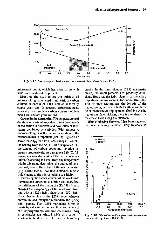
Influential Microstructural Features / 109
2000
Austenite (y) 10001670
1600800
!f- 1200 ~
l!F Ferrite (a) + carbide (C) 600 l!F::;] ::;]
i§ i§CD CDc. 800 c.E 400 E
{!? {!?
400 200Lath
martensite0
0 0.2 0.4 0.6 0.8 1.0 1.2 1.4 1.6 1.8
Carbon, wt"10
Fig. 5.17 Morphological classification of martensite in Fe-C alloys. Source: Ref 26
Fig. 5.18 Effect of austenitizing temperature on microcrack sensitivity. Source: Ref 33,37
cracks. In the long, slender {225} martensiteplates, the impingements are generally collisions. However, the habit plane is of secondaryimportance in microcrack formation (Ref 34).The primary factors are the length of themartensite or, perhaps, a high length to width ratio at the instant of impingement (Ref 34). As themartensite plate thickens, there is a tendency forthe cracks to be along the interface.
Effect of Alloying Elements. It has been suggestedthat microcracking is more likely to occur in
2200OF1204°C
t600 1800 2000871 982 1093Austenitizing temperature
o Ref33• Ref37
VII
)IJI
Fe-1.39%C
o 1400760
.. 20EE
iis~ 15
~tllECDE::>
110
~U 5
25
microcrack count, which has more to do withhow much martensite is present.
Most of the studies on the subject ofmicrocracking have used steel with a carboncontent in excess of 1.0% and an inherentlycoarse grain size. In contrast, carburized steelsgenerally have surface carbon contents of lessthan 1.0% and are grain refined.
Carbon in the Martensite. The temperature andduration of austenitizing determines how muchof the carbon is dissolved and how much of it remains combined as carbides. With respect tomicrocracking, it is the carbon in solution in themartensite that is important (Ref 33). Figure 5.17showsthe Accm for a Fe-1.39%Calloy is -920°C.On heating from the ACl (-710 "C) up to 920°C,the amount of carbon going into solution increases progressively. At and above 920 °C, following a reasonable soak, all the carbon is in solution. Quenching the steel from any temperaturewithin this range determines the degree of solution and, hence, the extent of the microcracking(Fig. 5.18). Once full solution is attained, there islittle change to the microcracking sensitivity.
Increasing the carbon content of the martensiteincreases the tetragonal distortion and, therefore,the brittleness of the martensite (Ref 33). It alsochanges the morphology of the martensite fromone with a {225} habit plane to a {259} habitplane. Nickel favors the {259} type, whereaschromium and manganese stabilize the {225}habit planes. The {259} martensite forms inbursts by autocatalytic action; therefore, many ofthe impingements are not collisions. Anymicrocracks associated with this type ofmartensite tend to be interface or boundary

110 / Carburizing: Microstructures and Properties
Grain size. ASTM scale
Fig. 5.19 Influence of grain size on microcrack frequency in some carburized steels.Source: Ref32
steels for which the major alloying elements arethe carbide formers (Ref 35). On the other hand,Davies and Magee (Ref 34) do not regard alloying elements (Ni, Cr, Mn) as having a direct influence on microcracking. Indirectly, though, alloying elements do alter the martensite habitplane of high-carbon materials and can therebyaffect the microcrack event. In commerciallyheat treated parts, bearing steel 52100 and casehardened, coarse-grained, SAE 8620 steels havereceived the most attention. Neither of thesesteels is particularly well alloyed; there are manycase-hardening grades more heavily alloyed, yetthe microcracking incidence seems to be noworse. What these two steels can have in common is the carbon content, and of the elementsadded to steels, carbon is the most potent withrespect to microcracking.
Plate Size and Grain Size. Although microcracks are known to occur in small martensiteplates (Ref 32, 36), they are most frequently observed in the larger plates (Ref 32, 34). The highest density is associated with the longest andthinnest plates, presumably because the largerplates are likely to be subjected to more impingements by other large plates striking themat the necessary velocity and tip strain energy(Ref 34). The maximum plate size, or volume, isdirectly related to the grain size and, therefore,
9 p
I /,1018 rimmed IIsteel ~
,IZ11 ~22 Si-killed
I coarse grain
/ 0 ~arbUriJed orcarbonitrided at _
/; 900°C8620 + Carburized or
\ carbonitrided at843 °C -\5 (III V Grain refined at788 °C
, ,V1018 AI-treat~d*,~<J-fine wain
it might be expected that microcrack incidenceincreases with austenite grain size, up to a point(to 200 urn grain diameter according to Ref 34).Rauch and Thurtle (Ref 32) were in agreement,stating that both the frequency and the size ofmicrocracks increased with grain size (Fig.5.19). Brobst and Krauss (Ref 30), studying aFe-l.22%C alloy, also confirmed that there werefewer cracks in the smaller grains, but for thosecracks which did form, the proportion of grainboundary cracks had increased.
Quench Severity.Kern (Ref 35) suggested thatvigorous quenching contributes to microcrackformation. However, this conclusion is not supported by laboratory tests in which waterquenching, oil quenching, or simulatedmartempering are employed (Ref 37) or wherequenching into 3% caustic solution, oil at 60 °C,or a salt bath at 180°C are utilized (Ref 32).Microcracks formed regardless of the type ofquenching used, thereby implying that quenchseverity is not significant.
Tempering. Microcracking in case-hardenedsurfaces may be aggravated by the presence ofhydrogen, which is absorbed during carburizingand reheating in an endothermic atmosphere.Welding research indicates that the microcracking of martensite in the heat affected zoneof a weld is influenced by the presence of hydrogen (Ref 38). For example, the martensite of aweld cooled to and soaked at temperatures above150°C is free from microcracking, whereas acomparable weld cooled to below 130°C contains microcracks even when soaked at that temperature. When microcracks exist in the weldarea, major cracks propagate from them due tothe action of low applied loads and delayed hydrogen cracking (Ref 39).
Conventionally carburized and freshly quenched parts contain hydrogen, may containmicrocracks, and are somewhat brittle. It wouldseem prudent, therefore, to temper componentssoon after quenching to drive off the hydrogenand reduce the risk of delayed cracking. Immediate tempering would also induce some measureof microstress relaxation to toughenthe martensite!austenite structure. Tempering has an added benefit of causing the smaller microcracks to heal(Ref 4Q--42), and tempering at temperatures aslow as 180°C for as little as 20 min has beenshown to have a marked effect (Fig. 5.20).Healing is attributed to volume changes and associated plastic flow (Ref 42).
2345678
2
14
16
4
x 12§~
110 / Carburizing: Microstructures and Properties
steels for which the major alloying elements are the carbide formers (Ref 35). On the other hand, Davies and Magee (Ref 34) do not regard alloying elements (Ni, Cr, Mn) as having a direct influence on microcracking. Indirectly, though, alloying elements do alter the martensite habit plane of high-carbon materials and can thereby affect the microcrack event. In commercially heat treated parts, bearing steel 52100 and case-hardened, coarse-grained, SAE 8620 steels have received the most attention. Neither of these steels is particularly well alloyed; there are many case-hardening grades more heavily alloyed, yet the microcracking incidence seems to be no worse. What these two steels can have in common is the carbon content, and of the elements added to steels, carbon is the most potent with respect to microcracking.
Plate Size and Grain Size. Although micro-cracks are known to occur in small martensite plates (Ref 32, 36), they are most frequently observed in the larger plates (Ref 32, 34). The highest density is associated with the longest and thinnest plates, presumably because the larger plates are likely to be subjected to more impingements by other large plates striking them at the necessary velocity and tip strain energy (Ref 34). The maximum plate size, or volume, is directly related to the grain size and, therefore,
16
14
x 12 o o o
10
£ 6 O Carburized or
carbonitrided at 900 °C
•+ Carburized or carbonitrided at 843 °C
V Grain refined at 788 °C
1018 Al-treated fine grain
Grain size, ASTM scale Fig. 5.19 Influence of grain size on microcrack frequency in some carburized steels. Source: Ref 32
it might be expected that microcrack incidence increases with austenite grain size, up to a point (to 200 u,m grain diameter according to Ref 34). Rauch and Thurtle (Ref 32) were in agreement, stating that both the frequency and the size of microcracks increased with grain size (Fig. 5.19). Brobst and Krauss (Ref 30), studying a Fe-1.22%C alloy, also confirmed that there were fewer cracks in the smaller grains, but for those cracks which did form, the proportion of grain boundary cracks had increased.
Quench Severity. Kern (Ref 35) suggested that vigorous quenching contributes to microcrack formation. However, this conclusion is not supported by laboratory tests in which water quenching, oil quenching, or simulated martempering are employed (Ref 37) or where quenching into 3% caustic solution, oil at 60 °C, or a salt bath at 180 °C are utilized (Ref 32). Microcracks formed regardless of the type of quenching used, thereby implying that quench severity is not significant.
Tempering. Microcracking in case-hardened surfaces may be aggravated by the presence of hydrogen, which is absorbed during carburizing and reheating in an endothermic atmosphere. Welding research indicates that the microcracking of martensite in the heat affected zone of a weld is influenced by the presence of hydrogen (Ref 38). For example, the martensite of a weld cooled to and soaked at temperatures above 150 °C is free from microcracking, whereas a comparable weld cooled to below 130 °C contains microcracks even when soaked at that temperature. When microcracks exist in the weld area, major cracks propagate from them due to the action of low applied loads and delayed hydrogen cracking (Ref 39).
Conventionally carburized and freshly quenched parts contain hydrogen, may contain microcracks, and are somewhat brittle. It would seem prudent, therefore, to temper components soon after quenching to drive off the hydrogen and reduce the risk of delayed cracking. Immediate tempering would also induce some measure of microstress relaxation to toughen the martensite/ austenite structure. Tempering has an added benefit of causing the smaller microcracks to heal (Ref 40-42), and tempering at temperatures as low as 180 °C for as little as 20 min has been shown to have a marked effect (Fig. 5.20). Healing is attributed to volume changes and associated plastic flow (Ref 42).

Influential Microstructural Features / 111
Temperingtemperature.·F
100 l..-.L---'---'--'_L.--->----'-----'----'_-'--'-------'---.JAQ 200 300400500 600 700 BOO 9001000110012001300
10 h
Fe-l.2C
o lBO·C
• 200·C• 225·C• As quenched
1 h
Time, S
10min14
<a>
oLl0"'2~~~.....L.,..-~~~.u.J..,-~~~",":-<--'--'
(b)
Tempering temperature. °C
AQ 100 200 300 400 500 600 700
2000
"/0~ 1000
TI •e!c'0 500;;; 400 •.0
300E::l ,Z ,
200,
Fig. 5.20 Influence of tempering on microcracking.(a) Effect of tempering temperature on the number ofcracks per unit volume. (b) Effect of tempering temperature and time on SV' microcrack area per unit volume ofspecimen. Source: Ref 41,42
consider, it is difficult to assess the contributionof anyone of them. Even so, Apple and Krauss(Ref 43), through examining the data includingfracture characteristics, concluded that the difference between the fatigue strength of the direct quenched and reheat quenched samplesmay be attributed to the differences in microcrack distribution and size. Also, the absence ofmicrocracks at the immediate surface of the double reheated samples may, in part, account forthe relatively superior test results. In viewingthese results, one might speculate that grain sizeand hardness accounted for about 80% of the difference in fatigue results, and microcracking accounts for the rest.
Of the three heat-treated conditions (Ref 43),the largest microcracks were observed in thedouble quenched samples, although the crack severity was the least. However, the overall maximum crack severity was not at the surface butabout 0.1 to 0.2 mm beneath the surface.Panhans and Fournelle (Ref 44) reported the
Effect of Microcracking on Properties. Microcracking has attracted attention in terms ofcauses and contributing factors, but few studies,as yet, have been carried out to determine the effect of microcracking on the more important material properties of heat-treated bearing steels orcase-hardened steels. Occasionally, prematurefailures have been attributed to the presence ofmicrocracks, but in failure analyses, there aregenerally so many variables involved that it isdifficult to isolate the primary contributor to failure.
The presence of microcracks implies thatstructural microstresses have been relieved bymicrocrack formation. However, now the cracksmust be regarded as stress concentrators, and thefollowing questions apply. Are the cracks largeenough to be significant as initiators of servicecracks? Do they generally reside in locations ofmaximum potency? The cracks are mostly located within the confines of the prior austenitegrain. If a service crack initiates at a grainboundary and starts to propagate along the grainboundaries, most of the microcracks are out ofharm's way. When a service crack is, or becomes, transgranular, microcracks would likelyhasten its propagation. As yet there is no clearevidence of just how detrimental microcracks areto the service life of a component. Mostmicrocracks are probably not close enough to thesurface and not of critical defect proportions toinitiate a trans granular service crack. Nevertheless, a crack is a crack, and it should be regardedwith some mistrust.
If it is assumed that cracks will be closed bycompressive macrostresses and opened by tensile macrostresses, then the influence of microcracks could vary according to situation. Carburized and hardened cases contain residual compressive macrostresses, which reduce any knownor unknown adverse traits that microcracksmight have. Through-hardened high-carbonsteels, on the other hand, might have surfaces inwhich the residual macrostresses are decidedlytensile after quenching. The macrostresses in thisinstance add to any adverse influence of themicrocracks.
Influence on Fatigue. Apple and Krauss (Ref43) investigated the influence of microcrackingon the fatigue resistance of case-hardened samples, using different quenching treatments tovary the microcrack population. The quenchingtreatments led to differences in grain size, hardness, retained austenite content, and microcrackdensity (Fig. 5.21). With so many variables to

112 / Carburizing: Microstructures and Properties
same findings. Removal of a surface layer, bywhatever means, could actually bring the zone ofmaximum crack incidence to the surface.
Control of Microcracking. The use of graincontrolled steels and the control of carburizingcondition to limit surface carbon content help reduce the likelihood of microcrack formation.The quenching conditions then become importantto ensure that the grain size remains fine.
High-temperature carburizing at greater than1000 °C can produce coarse-grained or mixedcoarse-and-fine-grained microstructures, because the grain-coarsening temperature has beenexceeded. Ifgrain size and microcracking are related, a high incidence of microcracking mightbe expected when quenching a coarse-grainedmaterial from above the ACcm or with an in-
creased surface carbon content. When a steel iscarburized from 925 to 935°C and below theconditions necessary to promote grain coarsening, the resultant grain size is likely to be normalfor that quench. The extent of the microcrackingshould be less than it is for the high-temperaturetreatment. Again, an increase of the carbon content could lead to more microcracks.
Quenching from below the Accm produces afiner grain size and forms carbides in high-carbonsurfaces (or the lack of carbide solution during reheating for quenching). If some of the carbon istied up as carbides, then the matrix material has alower carbon content and, hence, a reduced risk ofmicrocracking during quenching. In reheatquenched materials, mierocracking is rare (Ref26). However, when considering a lower quench-
:5 0
A
Single, A
reheat \
~..
... ~oo 0
Directquench ---Q.g-.....-".....:1.-_
200
10'IEE
.~8
<IlCG>t:.,
6E
g'2
4::>lil~.,"'"0 2~0
<k
300
Doublereheat
Distance below surface. mm
0.5 1.0 1.5 2.0 2.5900 I I
3 65
800
60III 700G>C
~"E 55CIl 600 :J:s:Q. ~8 50c 500 ~~
45 8400 40
3000
40
35
Fig. 5.21 Hardness, retained austenite, microcrack density, and bending fatigue curves for carburized and hardenedSAE 8620 steel quenched by three methods: direct quench, ASTM 1-3 grain size; single reheat, ASTM 4-5 grain size;double reheat. Source: Ref43

Influential Microstructural Features /113
ing temperature to control microcracking, it isnecessary to be mindful of the effect thatlow-temperature quenching will have on the coremicrostructure. If ferrite is unacceptable in thecore, then there is a limit to how low the quenching temperature can be reduced.
Krauss (Ref 26) reported that quenching aninitially coarse-grained steel from below theAccrn causes fine microstructural features, fewmicrocracks, and that on testing the overloadfractures were transgranular. Quenching fromabove the ACcm produces a coarse-grained structure, microcracks, and predominantly intergranular overload fractures.
The rate of quenching has already been discussed; it has little significance on microcrackseverity. Interrupted quenching, on the otherhand, is very significant. Lyman (Ref 46), investigating microcracking in AISI 52100 steel,quenched the austenitized samples into oil heldat a temperature just below the M, (138°C) ofthe steel. After an appropriate dwell, the sampleswere transferred into a salt bath held at 260 °Cand then quenched off. The aim was to temper,stress relieve, and toughen the first formedmartensite. The results are as follows:
• Without the 260 °C temper, simply an arrestat just below the M, before continuing thequench, microcracking was severe.
• When the sub-M, arrest prior to 260°C temper produced -10 to 20% martensite, only afew microcracks formed.
• When the martensite formed prior to temper-ing was -30 to 40%, no microcracks formed.
Clearly, there are a number of ways of controllingmicrocracking, including tempering, which canheal the smaller microcracks.
specification range. What is of more concern isthe variability that occurs on a microscale oververy small distances. This variability is referredto as microsegregation.
Formation ofMicrosegregation
Ingot Solidification. Microsegregation of steelsarises during the solidification process. In thissection, only microsegregation caused by solidification following casting is discussed. Subsequent segregation of elements during heat treatments, such as the segregation of phosphorus toaustenite grain boundaries during austenitizingprior to quenching, is not addressed here.
When a steel is cast into the ingot mold, thefirst material to solidify is that adjacent to thecooler mold walls. If there is no special preparation applied to the mold walls to slow the coolingrate, then the first metal to solidify, called a"chilled" surface layer, is a thin layer of smallequiaxed crystals with the same composition asthe liquid metal. At the inner surface of thechilled layer, the situation is energetically favorable for crystals above a critical size to continuegrowing inward. The growth is cellular initiallybut soon gives way to dendritic growth parallelto the thermal gradient. The dendrites grow long(see the columnar zone, Fig. 5.22 and 5.23), butsuch growth slows as the thermal gradient becomes flatter. Meanwhile, in the liquid ahead ofthe thermal gradient when the temperature hasfallen sufficiently, nucleation takes place at manysites ( i.e., on suitable substrates, such as nonmetallic inclusions), followed by uniform dendriticgrowth at each site until solidification terminates
Sinkhead
segregation
Columnarstructure
~:-':;';~-High
segregationand centerporosity
Negativesegregationequiaxedstructure
r~:=;l::J.--Shrinkagecavity
Inverted "V""A" segregation
Dendritic--\:;~
structure
Sedimentaryoxide
contaminationinclusions
Fig. 5.22 Schematic illustrating macrosegregationin a largesteel ingot
Maximumpositivesegregation
Ingot shellequiaxedstructureFor design purposes, it is generally assumed
that steels are homogenous. Unfortunately, theyare not. Macrochemical analysis surveys of ingots cast from a single ladle of molten steel reveal differences of composition. These surveysalso show that composition varies from the bottom to the top and from the center to the outsideof each ingot. A batch of forgings made from asingle ingot will therefore exhibit part-to-partcomposition variability, as well as variationswithin each part. However, such variations donot generally depart from the intended steel
Microsegregation

% impurity --+
114 / Carburizing: Microstructures and Properties
when neighboring grains impinge. These grainsconstitute the equiaxed grained zone at the centerof the ingot.
The Development of Microsegregation. An alloy of composition Xo is presented in the hypothetical constitution diagram of Fig. 5.24. Whenthe temperature of the molten metal falls to theliquidus at Xl, solid material of compositionA1 nucleates within the melt. With further cooling, the composition of any growing crystalchanges from A1 at its center through to A4 onits surface. Meanwhile, the composition of thesurrounding liquid changes from X1 to X4,which is the last of the liquid to solidify. Therefore, there is a distinct difference in impurity orsolute content between the first and the last materials to solidify. This difference is what iscalled ''microsegregation.'' Figure 5.25 shows anexample of microsegregation in which the composition of a cross section of a dendrite is recorded (Ref 47). It shows a comparatively lowsolute content, in this case nickel and chromium,at the center of the dendrite.
As the columnar grains grow forward together from the surface (Fig. 5.23), they pushthe more impure liquid ahead of them towardthe central zone. Therefore, the central zonecontains more of the impure material than thecolumnar zone. When the central zone has almost solidified, the least pure liquid, includingthe lower melting point nonmetallic inclusions, has nowhere to go except to the interfaces between the impinging dendrites. Consequently, on final solidification, the central zoneis the more heavily macro- and microsegregated(Fig. 5.26). Laren and Fredriksson (Ref 47) observed that the maximum microsegregation in 1and 9 ton ingots occurs at three-fourths of thedistance from the surface to the center of the ingot.
Steels solidify in the manner described, although the proportion of columnar growth to
Fineequiaxedchillcrystals
COlumn~ar~_-t~~~':;I:1jgrains -
Equiaxedgrains
Fig. 5.23 Section through a conventionally cast ingot
equiaxed growth varies depending on the lengthand steepness of the thermal gradient. Thus, themode of solidification is essentially columnar forcontinuously cast steels and equiaxed for verylarge conventionally cast ingots.
Microsegregation Tendencies of Alloying Elements. Steels are complex alloys containingmany elements. Some elements are intentionaland wanted, and others are residual and possiblyunwanted. Each element has its own segregationtendency, although in some instances the segregation tendency of one element can be modifiedby the presence of others. For example, siliconand manganese influence the segregation of molybdenum, and manganese influences that of sulfur. The generally accepted order of the susceptibility of elements to segregation is, from mostprone to least: sulfur, niobium, phosphorus, tin,arsenic, molybdenum, chromium, silicon, manganese, and nickel. Table 5.5 provides a basis ofcomparison for some of the common elements.Table 5.5 clearly indicates that, when solidification has been directional (columnar growth), theintensity of segregation is less than in the central,equiaxed grain zone.
The Effect of Mechanical and Thermal Treatments. Case-hardening steels are generally supplied in the wrought condition, that is hot rolledor forged to some convenient shape and size.During these hot-working processes, the microsegregated areas are given a directionality related
·Xo
Liquid
IComposition of first Composition of lastmetal to solidify metalto solidify
Fig. 5.24 Schematic constitutional diagram of howcompositional variations develop during solidification
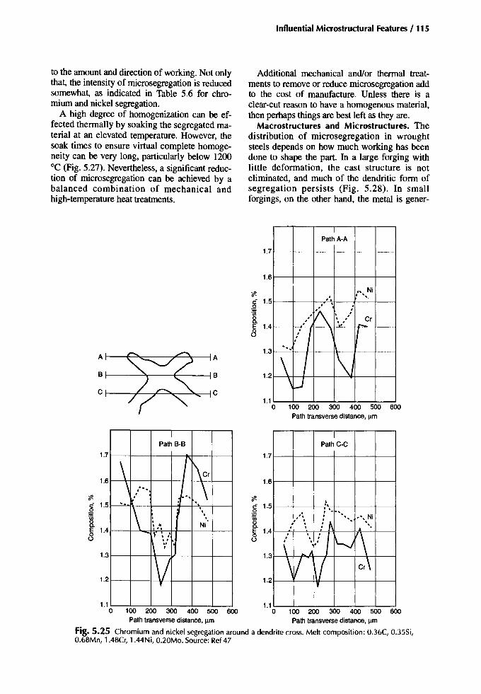
Influential Microstructural Features /115
to the amount and direction of working. Not onlythat, the intensity of microsegregation is reducedsomewhat, as indicated in Table 5.6 for chromium and nickel segregation.
A high degree of homogenization can be effected thermally by soaking the segregated material at an elevated temperature. However, thesoak times to ensure virtual complete homogeneity can be very long, particularly below 1200°C (Fig. 5.27). Nevertheless, a significant reduction of microsegregation can be achieved by abalanced combination of mechanical andhigh-temperature heat treatments.
Additional mechanical and/or thermal treatments to remove or reduce microsegregation addto the cost of manufacture. Unless there is aclear-cut reason to have a homogenous material,then perhaps things are best left as they are.
Macrostructures and Microstructures. Thedistribution of microsegregation in wroughtsteels depends on how much working has beendone to shape the part. In a large forging withlittle deformation, the cast structure is noteliminated, and much of the dendritic form ofsegregation persists (Fig. 5.28). In smallforgings, on the other hand, the metal is gener-
IPath A-A
" Ni. I "I,
I,
I
V\.
I , ..CrI , I
I ."I I-
i I \ J'"
\ I 1\\lJ
1.3
1.4
1.5
1.2
1.6
1.7
1.1o 100 200 300 400 500 600
Pathtransverse distance,11m
<ft..:0
~8.E0o
A A
B B
C C
IPathC-C
~·,. ·. ,"' , · ... "'., NiI ,
,: f\. ' "I . •
I ..'\I , I
1'-..1I • I
\ ... .11 /
\1/ 1\( cr\
I'
1
1.2
<ft..: 1.5o~8.E 1.4oo
1.3
1.6
1.7
IPathB-B
\ 'I\cr
\ I· ..... I, \I
~'r:
",
1\,,,· .· Ni·.."
~ . ,• I
"1\ ~'
2 \/,11. 1.o 100 200 300 400 500 600 0 100 200 300 400 500 600
Pathtransversedistance, IlITI Pathtransverse distance,11m
Fig. 5.25 Chromium and nickel segregation around a dendrite cross. Melt composition: O.36C, 0.35Si,O.68Mn, 1.48Cr, 1.44Ni, O.20Mo. Source: Ref 47
1.3
1.6
1.
1.7

116 / Carburizing: Microstructures and Properties
ally more severely worked. While segregation,albeit less intense, survives the mechanical treatment, it is redistributed as alloy-rich and alloy-lean bands flowing in directions dictated bythe working process (Fig. 5.29, 5.30).
In microsegregated materials, the heat treatment response of the alloy-rich areas is differentfrom that of the alloy-lean areas. Consequently,it is possible for each to transform at differenttimes and to different products on cooling fromthe austenitizing temperature. In low- and mediumcarbon steels, austenitized and slow cooled, themicrosegregation is identified as alternating areas of ferrite and pearlite (banding).
Reaustenitizing and fast cooling in the pearlitic range causes the carbon to redistribute fairlyevenly to give the impression that the segregationhas been removed. Unfortunately, the alloy segregation will still be there, essentially unaffected.It is merely masked by the redistributed carbon.In the surface of a carburized case where the carbon may be evenly distributed, the presence ofmicrosegregation might be detected by observing alternate areas of martensite and bainite or of
Table 5.5 Segregation indices for some elementsin steel
AlloyingelementSegregationindex (lS)(a)
Columnar crystals Equiaxed c!JStais
1.47-2.101.10-1.500.40-1.95
1.9-7.3>2000>170-75
Columnar crystals Equiaxed crystalsABC ABC
2.051.23
1.31-1.381.06-1.241.07-1.271.70-2.00
ChromiumNickelManganeseMolybdenumNiobiumPhosphorusArsenic
Alloyingelement
Table5.6 Changes in microsegregation intensitydue to hot working between 1200 and 1000 °C
Segregationindex (IS)
(a) (Concentration at interdendritic site)/(concentration at dendriticcore). Source:Ref48,49
400300200100O~--~----=-=--_---=-~__---Jo
Distance fromingotsurface. mm
Distance fromingotsurface. mm
Fig. 5.26 Maximum and minimum chromium concentrations asa function of distance from surface. Source:Ref47
1.15 1.16 1.72 1.54 1.35 1.691.08 1.12 1.45 1.20 1.14 1.461.12 1.08 1.40 1.30 1.27 1.421.02 1.08 1.39 1.29 1.05 1.39
1.0co
~~
0.80>Q>.,e0'E
0.6'0Q>"0
~Ci
0.4Etil
.5co.2U 0.2::::I
ala:
Chromium(ascast)Chromium(98%reduction)Nickel (as cast)Nickel (98%reduction)
Source:Ref 50
100 200 300 400 500Soaktime, h
Fig. 5.27 Effect of homogenization temperature andtime on the intensity of manganese segregation in anEN39 steel. Source: Ref 51
400300200100o
1 ton
IA
\\u,J
I.Y~Crmin
1 TJ.t-: T T
J. J.
~
0
'#. 3E::::I
.~
.co 2
4

austenite and martensite, depending on the actualcompositions and the cooling rates involved.Where the tempered martensite normally etchesdark, a light 2% nital etch should determine ifsignificant microsegregation is present.
Effects ofMicrosegregation on Properties
Influence on Hardness. Figure 5.31 (b-d)shows an example of the variations in microstructure that can result from the presence ofmicrosegregation; the cooling rates are those ofan end-quenched hardenability bar. Within thisrange of cooling rates, the alloy-rich areas havetransformed to either martensite or bainite.Meanwhile, the alloy-lean areas have transformed to martensite and bainite with increasing
amounts of pearlite and ferrite with the slowercooling rates. Figure 5.3I(a) relates these microstructures to the hardness.
Microsegrcgation influences the hardness ofthe case, particularly if it leads to local concentrations of retained austenite or bainite in themainly martensitic structure. Both austenite andbainite are softer than the martensite at a givencarbon level.
Influence on Tensile and Toughness Properties.The tensile strength and yield strength are unlikely to be affected by the presence or absenceof microsegregation. The ductility indicators, onthe other hand, will be affected. Kroneis et al.(Ref 53) showed that the reduction of area of aconventionallymelted and forged medium-carbonalloy steel (5: I to 10:I reductions) was about
100
Pearlite
Homogeneouszone
Homogeneous zone
Zone of max segregation
Zone of max segregation
Zoneof:m~in~g~3~El~Jsegregation
!artensiteV- I Ferrite Pearlite
1/Bainite
Iaa
600
0>IullJlQ)<::
12 200CllI
a
100
50
a
ulc:o
Ia. 1005 MU 502
Cii20 40 60 80
Distancefrom end face, mm
Fig. 5.31 Hardenability curves and correspondingmicrostructures for a 25CrMo4 steel. Source: Ref 52
Fig. 5.29 Sect io n throu gh a forged slid ing clut ch hub.o.a-
Zone of min segregation
Fig. 5.28 Dendritic microsegregation in a fracturedgear tooth.2x
Fig. 5.30 Microstructure of an air-cooled carburizedbarend.50x

\ 5;eel: ~38 CrMoV51\ after four-fold reduction
\
:\.\I,
r-...""1'0
118 I (arburizing: Microstructures and Properties
doubled by special treatment to remove the microsegregation. An electroslag melted steel wasalso improved by the same balanced mechanicaland thermal treatment. At tensile strengths typical for the core of a carburized part made from awrought blank, it is unlikely that microsegregation has much influence on ductility and toughness indicators in the longitudinal direction. Onthe other hand, it does have a pronounced negative affect on those properties in the transversedirection (Fig. 5.32).
Influence on Fatigue. It is difficult to determine the effect of microsegregation alone onthe various properties of a steel because of thepresence of nonmetallic inclusions. Similarly, itis difficult to isolate the influence of nonmetallic inclusions on properties. However, if it is assumed that electroslag remelted (ESR) steels areessentially cleaner than the conventionallymelted steels, then some measure of the respective influences of microsegregation and nonmetallic inclusions can beobtained.
Kroneis et al. (Ref 53, 54) carried out such acomparison using a Cr-Mo-V steel and showedthe ESR steel to have superior general properties.In this way, the effect of nonmetallic inclusionsin particular could be assessed. With a specialtreatment to reduce the microsegregation of thesteels melted by the two processes (ESR andconventional), the properties of each were furtherimproved. For example, the bending fatiguestrength of the ESR material (Fig. 5.33) was superior to that of the conventionally melted steel.Therefore, the conclusion is that nonmetallic inclusions have a significant influence on the fatigue strength of this particular high-strength,through-hardened, and tempered steel. The fa-
40
36
<f1. 32..; 28
~ 24
.~ 20o:g 16~
~ 1284o1.0 1.1 1.2 1.3 1.4 1.5 1.6 1.7 1.8 1.9 2.0
Degreeof segregation: (MomaxokIMomin%)
Fig. 5.32 Dependence of reduction of area of transverse specimens on degree of molybdenum segregation.Hardened and tempered; tensile strength, 1550 to 1770MPa. Source: Ref 54
tigue strength of the ESR steel is improved evenfurther by applying a special treatment to reducethe severity of the microsegregation. The fatiguelimit of the conventionally melted steel is littleenhanced by the special treatment, although inthe high-stress, low-cycle region, the treatmentdid lead to an improvement.
What these tests suggest is that for high-cyclefatigue applications, the effect of nonmetallic inclusions far outweigh any adverse influences ofmicrosegregation. Presumably, the nonmetallicsprovide sites at which fatigue cracks can initiateand from which they can grow. In the low-cycledomain (in this example, <2 x lOS cycles), microsegregation appears to be more influential thannonmetallic inclusions.
These test results (Ref 53,54) refer to a highstrength, through-hardened material, andwhether the same trends apply to a carburizedand hardened part is not really known. Nonetheless, some speculation can be made. For example, for the core, there will be a similar trend:microsegregation can affect low-cycle fatigueand have little, if any, influence on the highcycle fatigue strength. For thecase, the local transformation behavior might be affected by microsegregation. However, the effect will be detrimental only if it leads to the formation of mixedmicrostructures, such as martensite plus bainiteor martensite plus austenite, depending on thegrade of steel. If, for example, the retained austenite at a carburized and hardened surface ispatchy, varying appreciably over short distancesdue to microsegregation (Fig. 5.34a, b), then themicrohardness will vary accordingly, as too willthe local residual macro- and microstresses. Thebending fatigue strength would then approachthat of the softer transformation product.
8!. ±900 .----......-....,....~==-==-===-,~
£ ±800 1--.....:::~----:~~F=,=,;==::~:7=::-+Cl
~'Iii ±700Q)~
g ±SOO 1----:1----+----+----::1.l!!Cl
=6 ±500 1----"""'oE''''''''"=y.~ :"''C'''''''''-'f''=';=''''''iF'
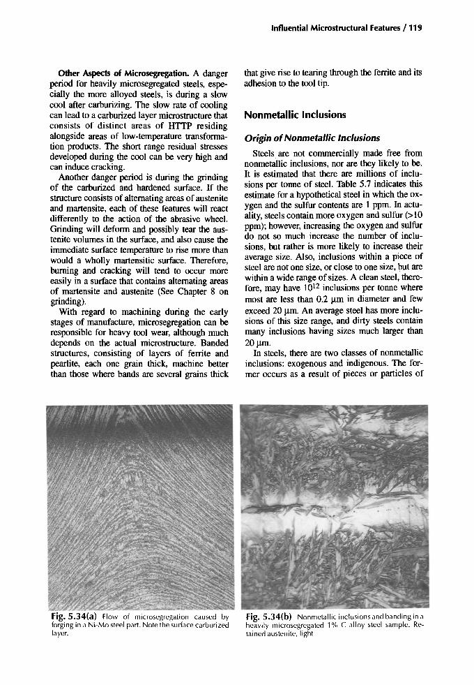
Other Aspects of Microsegregation. A dangerperiod for heavily microsegregated steels, especially the more alloyed steels, is during a slowcool after carburizing. The slow rate of coolingcan lead to a carburized layer microstructure thatconsists of distinct areas of HTIP residingalongside areas of low-temperature transformation products. The short range residual stressesdeveloped during the cool can be very high andcan induce cracking.
Another danger period is during the grindingof the carburized and hardened surface. If thestructure consists of alternating areas of austeniteand martensite, each of these features will reactdifferently to the action of the abrasive wheel.Grinding will deform and possibly tear the austenite volumes in the surface, and also cause theimmediate surface temperature to rise more thanwould a wholly martensitic surface. Therefore,burning and cracking will tend to occur moreeasily in a surface that contains alternating areasof martensite and austenite (See Chapter 8 ongrinding).
With regard to machining during the earlystages of manufacture, microsegregation can beresponsible for heavy tool wear, although muchdepends on the actual microstructure. Bandedstructures, consisting of layers of ferrite andpearlite, each one grain thick, machine betterthan those where bands are several grains thick
'" ""~~~Fig. 5.34(a) Flow of microsegregation caused byforging in a Ni-Mo steel part. Note the surface carburizedlayer.
Influential Microstructural Features / 119
that give rise to tearing through the ferrite and itsadhesion to the tool tip.
Nonmetallic Inclusions
Origin ofNonmetallic Inclusions
Steels. are not commercially made free fromnonmetallic inclusions, nor are they likely to be.It is estimated that there are millions of inclusions per tonne of steel. Table 5.7 indicates thisestimate for a hypothetical steel in which the oxygen and the sulfur contents are 1 ppm. In actuality, steels contain more oxygen and sulfur (>10ppm); however, increasing the oxygen and sulfurdo not so much increase the number of inclusions, but rather is more likely to increase theiraverage size. Also, inclusions within a piece ofsteel are not one size, or close to one size, but arewithin a wide range of sizes. A clean steel, therefore, may have 1012 inclusions per tonne wheremost are less than 0.2 urn in diameter and fewexceed 20 urn. An average steel has more inclusions of this size range, and dirty steels containmany inclusions having sizes much larger than20~m.
In steels, there are two classes of nonmetallicinclusions: exogenous and indigenous. The former occurs as a result of pieces or particles of
Fig. 5.34(b) Nonmetallic inclusions and banding in aheavily microsegregated 1% C alloy steel sample. Retained austenite, light
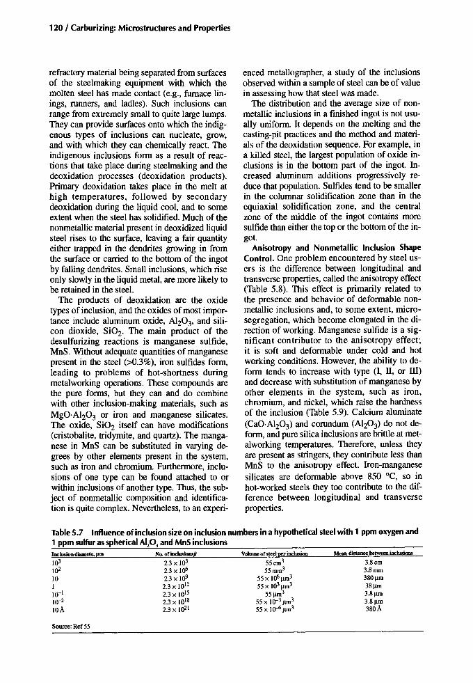
120 / Carburizing: Microstructures and Properties
refractory material being separated from surfacesof the steelmaking equipment with which themolten steel has made contact (e.g., furnace linings, runners, and ladles). Such inclusions canrange from extremely small to quite large lumps.They can provide surfaces onto which the indigenous types of inclusions can nucleate, grow,and with which they can chemically react. Theindigenous inclusions form as a result of reactions that take place during steelmaking and thedeoxidation processes (deoxidation products).Primary deoxidation takes place in the melt athigh temperatures, followed by secondarydeoxidation during the liquid cool, and to someextent when the steel has solidified. Much of thenonmetallic material present in deoxidized liquidsteel rises to the surface, leaving a fair quantityeither trapped in the dendrites growing in fromthe surface or carried to the bottom of the ingotby falling dendrites. Small inclusions, which riseonly slowly in the liquid metal, are more likely tobe retained in the steel.
The products of deoxidation are the oxidetypes of inclusion, and the oxides of most importance include aluminum oxide, Al203, and silicon dioxide, Si02. The main product of thedesulfurizing reactions is manganese sulfide,MnS. Without adequate quantities of manganesepresent in the steel (>0.3%), iron sulfides form,leading to problems of hot-shortness duringmetalworking operations. These compounds arethe pure forms, but they can and do combinewith other inclusion-making materials, such asMgO·Al203 or iron and manganese silicates.The oxide, Si02 itself can have modifications(cristobalite, tridyrnite, and quartz). The manganese in MnS can be substituted in varying degrees by other elements present in the system,such as iron and chromium. Furthermore, inclusions of one type can be found attached to orwithin inclusions of another type. Thus, the subject of nonmetallic composition and identification is quite complex. Nevertheless, to an experi-
enced metallographer, a study of the inclusionsobserved within a sample of steel can be of valuein assessing how that steel was made.
The distribution and the average size of nonmetallic inclusions in a finished ingot is not usually uniform. It depends on the melting and thecasting-pit practices and the method and materials of the deoxidation sequence. For example, ina killed steel, the largest population of oxide inclusions is in the bottom part of the ingot. Increased aluminum additions progressively reduce that population. Sulfides tend to be smallerin the columnar solidification zone than in theequiaxial solidification zone, and the centralzone of the middle of the ingot contains moresulfide than either the top or the bottom of the ingot.
Anisotropy and Nonmetallic Indusion ShapeControl. One problem encountered by steel users is the difference between longitudinal andtransverse properties, called the anisotropy effect(Table 5.8). This effect is primarily related tothe presence and behavior of deformable nonmetallic inclusions and, to some extent, microsegregation, which become elongated in the direction of working. Manganese sulfide is a significant contributor to the anisotropy effect;it is soft and deformable under cold and hotworking conditions. However, the ability to deform tends to increase with type (I, Il, or ill)and decrease with substitution of manganese byother elements in the system, such as iron,chromium, and nickel, which raise the hardnessof the inclusion (Table 5.9). Calcium aluminate(CaO·AI203) and corundum (Al203) do not deform, and pure silica inclusions are brittle at metalworking temperatures. Therefore, unless theyare present as stringers, they contribute less thanMnS to the anisotropy effect. Iron-manganesesilicates are deformable above 850°C, so inhot-worked steels they too contribute to the difference between longitudinal and transverseproperties.
Table5.7 Influence of indusion size on indusion numbers in a hypothetical steel with 1 ppm oxygen and1 ppm sulfur as spherical Alp] and MnSindusionsIDclusion diamet.! f!Dl
103
10210110-110-2
lOA
Source:Ref55
No.oflnclusions(l
2.3 X UP2.3 X 106
2.3 X 10⁹
2.3 X 10¹²
2.3 X 10¹⁵
2.3 X 10¹⁸
2.3 X 10²¹
Volume of steel per Inclusion
55cm3
55mm3
55 X 106~m3
55x UP~m355~3
55x 1O-3~3
55 X IO...{;~3
Mean distanee between Inclusions
3.8cm3.8mm380~m
38~m
3.8~m
3.8~m
380A
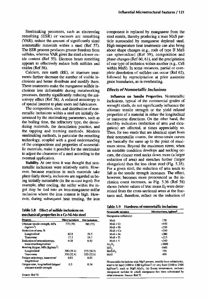
Steelmaking processes, such as electroslagremelting (ESR) or vacuum arc remelting(VAR), reduce the amount of significantly sizednonmetallic materials within a steel (Ref 57).The ESR process produces greater freedom fromsulfides, whereas VAR gives the steel a lower oxide content (Ref 55). Electron beam remeltingappears to effectively reduce both sulfides andoxides (Ref 58).
Calcium, rare earth (RE), or titanium treatments further decrease the number of visible inclusions and better distribute and modify them.These treatments make the manganese sulfide inclusions less deformable during metalworkingprocesses, thereby significantly reducing the anisotropy effect (Ref 58). A reduced anisotropy isof special interest to plate users and fabricators.
The composition, size, and distribution of nonmetallic inclusions within a steel are initially determined by the steelmaking parameters, such asthe boiling time, the refractory type, the deoxidizing materials, the deoxidation practice, andthe tapping and teeming methods. Modernsteelmaking methods, in particular the remeltingtechnology, coupled with a good understandingof the compositions and properties of nonmetallic materials, make it possible for the steelmakerto adjust the cleanness of a steel according to theeventual application.
Stability. At one time it was thought that nonmetallic inclusions were relatively stable. However, because reactions in such materials takeplace fairly slowly, inclusions are regarded as being initially metastable (in the as-cast ingot). Forexample, after cooling, the sulfur within the ingot may be tied into an iron-manganese-sulfurinclusion where the iron content is high. However, during subsequent heat treating, the iron
Influential Microstructural Features / 121
component is replaced by manganese from thesteel matrix, thereby producing a truer MnS particle surrounded by manganese depleted steel.High-temperature heat treatments can also bringabout shape changes (e.g., rods of type II MnScan spheroidize) (Ref 59), composition andphase changes (Ref 60,61), and the precipitationof one type of inclusion within another (e.g., CrSwithin MnS). In some instances, partial or complete dissolution of sulfides can occur (Ref 62),followed by reprecipitation at prior austenitegrain boundaries, as in overheating.
Effects ofNonmetallic Inclusions
Influence on Tensile Properties. Nonmetallicinclusions, typical of the commercial grades ofwrought steels, do not significantly influence theultimate tensile strength or the yield relatedproperties of a material in either the longitudinalor transverse directions. On the other hand, theductility indicators (reduction of area and elongation) are affected, at times appreciably so.Thus, for two steels that are identical apart fromtheir nonmetallic counts, the stress-strain curvesare basically the same up to the point of maximum stress. Beyond the maximum stress, whenan unstable condition develops and necking occurs, the cleaner steel necks down more (a largerreduction of area) and stretches further (largerelongation) than the less clean steel (Fig. 5.35).For a given steel, the reduction of area tends tofall as the tensile strength increases. The effect,however, becomes more pronounced as the inclusion count increases, as Fig. 5.36 (Ref 58)shows (where values of true strain Er were determined from the cross-sectional areas at the fractures and, therefore, reflect on the reduction of
Table5.8 Effectof sulfide inclusions onmechanical properties in a Cr-Ni-Mosteel
170<450<250<240<300<215<340
>30001600750400
Property
Ultimate tensile strength. MPa(kg/mm2)
Reduction of area.%LongitudinalTransverse
Reduction of areaanisotropy.transverse/longitudinal
Bending fatigue. MPa(kg/mm2)
LongitudinalTransverse
Fatigue anisotropy. transverse!longitudinal
Fatigue ratio. longitudinal fatigue!ultimate tensile strength
Source: Ref56
Many Inclusions
775 (79)
62.817.50.28
390(39.4)320(32.4)
0.82
0.5
FewiDe_ions
700(72)
59.529.70.50
375(38.5)320(32.6)
0.85
0.54
Table5.9 Hardness of nonmetallic inclusionsNoDJDetall1c: iDdusion Microbardness, Iq;f1DunZManganese sulfides(a)
MnSMnS+CrMnS+NiMnS+CoMnS+FeMnS+TiMnS+V
AI20 3Si02MnSi02MnO
Nonmetallic inclusions with MgO present. usually from refractories,tend to be hard (1000 to 1200 kgf/mm2) or very hard (2100 to 2400kgf/mm2), such as MgO·AI203. (a) Room temperature. includesmanganese sulfides in which manganese has been substituted byother elements. Source: Ref 55

122 / Carburizing: Microstructures and Properties
Maximum
Uncleansteelun
Extension
Fig. 5.35 Load/extension curves indicating the trendformed by steel cleanness
area). Ductility indicators are adversely affectedby any type of nonmetallic, but the stringer typeis more detrimental than the globular type (Ref63). Also, the more elongated the stringer is, theworse the effect will be.
The anisotropy effect due to metalworking hasalready been mentioned, though not in any detail. The ductility indicators in conventionallyproduced steels are lowest in the short transversedirection, intermediate in the long transverse direction, and highest in the longitudinal direction(Ref 64). The variation of reduction of area(ROA) relative to orientation is illustrated in Fig.5.37. An example of the effect that forging ratiohas on the ROA is shown in Fig. 5.38, whichshows that anisotropy increases with the amountof metalworking. However, these results arefrom about 1949; since then, steelmaking andmetalworking processes have advanced appreciably so that differences due to orientation canbe better controlled (Table 5.10). In the cleanergrades of steel, the difference in ductility between the longitudinal and long transverse directions can be kept small, although that for the
1.50 r-----,---...,--..,--,----...,------,---,--~_____,
0.60 0.80 1.00.400.200.06 0.080.10
-- 900 MPa tensile strength
- - - 1150 MPa tensile strength
0:--+---+-+--- 1850 MPa tensile strength
0.04
0.25 ~---+--l--+-+--'::~~W
0.501------+----;-
1.25
Inclusions, mm/mm2
Fig. 5.36 Scatterbands for the tensile true fracture strain of a 0.4% C steel at three strength levels as afunction of the total inclusion projected length in the fracture plane. Inclusions, total projected length.Source: Ref58
short transverse direction lags some way behind.Even so, it might not be necessary to make steelswith equal ductility in all directions. The important achievement would be to have adequate ductility in the short-transverse direction, and thiscan be done by producing a low-sulfur steelalong with a RE treatment.
Both microsegregation and nonmetallic inclusions vary depending on where in the forging orbar the samples were taken. Consequently, because they both have an effect on the ductility indicators, the ductility should vary with location.Table 5.11 shows that near surface ductility is superior to that at the mid-radius or center locations. This comparison might be of interest togear manufacturers who, in general, cut the gearteeth in the near surface region of the forging orbar.
Influence on Fatigue Resistance. Leslie (in Ref65) considered that in the high-cycle regime(>1OS load cycles) nearly all fatigue cracks initiate at nonmetallic inclusions. In the low-cycle regime (l()3 to lOS load cycles) and especially inthe 101 to 1()3 cycle range, slip band cracks provide the initiation sites. The potency of a nonme-
Influential Microstructural Features / 123
tallic inclusion with respect to fatigue stressingdepends on the chemistry, size, location, andquantity of inclusions; strength of the steel; andthe residual stress state immediately adjacent tothe inclusion (Ref 66).
Effect of Inclusion Chemistry. The hard typesof inclusions that resist deformation during processes, such as rolling or forging, have a tendency to develop cone-shaped cavities in the direction of metal flow during the workingoperations (Ref 67). These cavities, which do notweld up again, increase the effective size and thestress-concentrating effect of the inclusion,thereby becoming more potent as a fatigue crackinitiation site. These hard, undeformable typesof inclusions, such as single-phase alumina(Alz0 3), spinels (e.g., MgO·Alz0 3), calciumaluminates (e.g., CaO-AIZ0 3), titanium nitride,and some silicates, all have lower thermal expansion coefficients than steel (Fig. 5.39). Therefore, a tensile stress field should develop aroundeach inclusion as a result of hardening heattreatments, and the tensile stresses could thenadd to any stresses applied in service. Thus, with
o ~ 40 60 60 100Angle,degrees
Fig. 5.37 Relationship between reduction of area andangle between the longitudinal direction in forging andthe specimen axis. Source: Ref 64
Longitudinal
70
~60
~~50c:
~4O:::>
~30
20
Transverse
l
<, <, Maximum
\ <,r--
au =1145 MPa \ Minimum
"-Y
72Longitudinal
68
~ 64ail!!as 60'0c:.2
56'0:::>'CGlII: 52
Forging ratio
Fig. 5.38 Effect of forging reduction on longitudinaland transverse reduction of area. TensiIe strength, 840MPa (118 ksi), Source: Ref64
Table5.10 Mechanical properties of 15NiCrMo16 5 carburizing steel after melting (after K. Vetter)Sulfur Degree of CUproof lenslle Elongationat tracture(a), "" Reduction ofarea, % Notch toughness(h), J/cnJ1.
Meltllllltype content, % delbrmation stress, MPa stress,MPa Longitudinal 'Iransverse Longitudinal 'Iransverse Longitudinal 'Iransverse
Conventionally 0.010 -6x 1160 1450 10 7 48 27 50 35melted(electricfurnace)
Electroslag 0.004 -6x 1160 1450 12 10 55 46 69remelted
Electron-beam 0.007-0.009 10 to 30x 1060--1120 1350-1420 13.5 13.5 58 51 83 65remelted
(a) lu =5do. (b) DVM specimen. Source: Ref 57

124 / Carburizing: Microstructuresand Properties
Table 5.11 Mechanical propertiesof heat-treatedforged barsofX41 CrMoV 51 steelPositioool Iagot type of EIongalion at fracture(a) Reductionofarea, " Radool~specimeo
specimen in ioRot -Jtinc Loqltudioal 'I'raonene LoogitudioaJ Transverse EIoogation Reductionofarea
Edge Conventionally melted 12 6 45 12 0.5 0.27(electricfurnace)
E1ectroslag remelted 12 12 45 43 \.0 0.97Y, radius Conventionally melted 10 2 34 5 0.2 0.15
(electricfurnace)Electroslagremelted 10 10 40 38 \.0 0.95
Center Conventionally melted 10 2 30 4 0.2 0.13(electricfurnace)
Electroslagremelted 10 9.5 40 36 0.95 0.90
Diametersfrom230to 350 mm;tensilestrengthsfrom 1550to 1700MPa;averagesof -200 heats.(a) 4, =5do. Source:Ref 57
respect to properties, the hardest nonmetallic inclusions are thought to be the most harmful (Ref68-70), and the softer inclusions, such as manganese sulfide and manganese oxide, are the leastharmful (Ref 70). The softer inclusions are essentially harmless even in high-strength bearingsteels (Ref 60), although there could be a littlemore life variability. A hard inclusion can berendered less deleterious if it contains or is en-
veloped by manganese sulfide. This is due in partto the deformability of manganese sulfide and inpart to the tendency of hard nonmetallic inclusions to be noncoherent with the ferrous matrix,whereas manganese sulfide is semi- coherent.
In general, the term "nonmetallic inclusion"refers to the exogenous and indigenous types.However, a third type develops by the intentional addition of lead, which is essentially im-
MnS
Alumina
Nitrides
Spinels(XOAI20 3)
Calciumaluminates
(c = c ao )A=AI203
Silicates (a)
(
c=cao)A= AJ203M=MnOS=Si02
Mean expansion coefficient (0-800 ec), U1X 10-f3rC
5 10 u2 15
--------------~~~~~--------------
co~c.E.§.<:o'iii::J(3.!:13a?::
Stress-raisingpotential Matrix?Void forming potenti~1
Fig. 5.39 Stress-raising propertiesof inclusions in 1%C-Crbearing steel.Source: Ref55
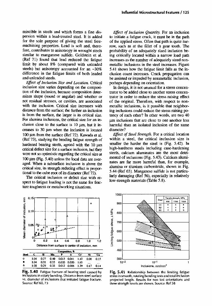
Influential Microstructural Features /125
miscible in steels and which fOnDS a fine dispersion within a lead-treated steel. It is addedfor the sole purpose of giving the steel freemachining properties. Lead is soft and, therefore, contributes to anisotropy in wrought steelssimilar to manganese sulfide. Goldstein et al.(Ref 71) found that lead reduced the fatiguelimit by about 8% (compared with unleadedsteels) but anisotropy accounted for an -30%difference in the fatigue limits of both leadedand unleaded steels.
Effect of Inclusion Size and Location. Criticalinclusion size varies depending on the composition of the inclusion, because composition determines shape (round or angular) and whether ornot residual stresses, or cavities, are associatedwith the inclusion. Critical size increases withdistance from the surface; the further an inclusionis from the surface, the larger is its critical size.For alumina inclusions, the critical size for an inclusion close to the surface is 10 urn, but it increases to 30 urn when the inclusion is located100 /lID from the surface (Ref 72). Kawada et al.(Ref 73), studying the bending fatigue strength ofhardened bearing steels, agreed with the 10 urncritical defect size for a surface inclusion, but theywere not so optimistic regarding the critical size at100 /lID (Fig. 5.40) unless the local data are averaged. When a subsurface inclusion is above thecritical size, its strength reducing effect is proportional to the cube root of its diameter (Ref 72).
The critical inclusion or defect size with respect to fatigue loading is not the same for fracture toughness or metalworking situations.
Effect of Inclusion Quantity. For an inclusionto initiate a fatigue crack, it must be in the pathof the applied stress. Often that path is quite narrow, such as at the fillet of a gear tooth. Theprobability of an adequately sized inclusion being critically located within a narrow load pathincreases as the number of adequately sized nonmetallic inclusions in the steel increases. Figure5.41 shows how the fatigue limit falls as the inclusion count increases. Crack propagation canbe assisted or impeded by nonmetallic inclusion,perhaps depending on orientation.
In design, it is not unusual for a stress concentrator to beadded close to another stress concentrator in order to reduce the stress raising effectof the original. Therefore, with respect to nonmetallic inclusions, is it possible that neighboring inclusions could reduce the stress raising potency of each other? In other words, are two 40urn inclusions that are close to one another lessharmful than an isolated inclusion of the samediameter?
Effect of Steel Strength. For a critical locationwithin a steel, the critical inclusion size issmaller the harder the steel is (Fig. 5.42). Inhigh-hardness steels including case-hardeningsteels, calcium aluminates are the most detrimental of inclusions (Fig. 5.43). Calcium aluminates are far more harmful than, for example,alumina or titanium carbonitride, shown in Fig.5.44 (Ref 65). Manganese sulfide is not particularly damaging (Ref 56), especially in relativelylow-strength materials (Table 5.8).
Composition, ...Steel C SI Mn P S Cr Ni Cu
0 1.04 0.27 0.40 0.013 0.011 1.43 0.08 0.15
• 1.04 0.31 0.35 0.020 0.020- 1.65~ 1.08 0.29 0.35 0.012 0.006 1.39 0.17 0.14
"
C
n,.." " .... ;..
.............0 ., ic1
•• I/o ••••I/o •••
0
Distance from surfaceto centerof inclusion, mm
Tensile strength, MPa
10-1
Inclusions, mm/mm2
1000
900
osa.800:2
+1enen
700~tiQ):::>Ol 600~Olc:..., 500-E::J
400
30010-2
1.21.00.80.60.40.2
E 0.15E
.§:::>~ 0.10
o!E 0.05.!!!'0c:81~ 0
o
Fi~. 5.40 Fatigue fracture of bearing steel caused byinclusions in rotary bending. Distance from steel surfacevs. diameter of inclusions that initiated fatigue fracture.Source: Ref 60,73
Fig.5.41 Relationship between the limiting fatiguestressin smooth, rotating bending testsand total inclusionprojected length. Results for two test orientations andthree strength levels are shown. Source: Ref 58

126 / Carburizing: Microstructures and Properties
Oa at 106
reversals =~ _
Su
2
Mean inclusion radius (rl. in.
Fig. 5.42 Effect of inclusion size (spherical) on the fatiguestrength of steel. Source: Ref 74
Effect ofResidual Stresses from Inclusions. Aspreviously mentioned, tensile stress fields candevelop around the harder type of nonmetallicinclusion, and cavities can form at hard inclusions during metalworking operations to act asstress raisers. Also, angular inclusions (Ref 75)or strings of fragmented inclusions can act asstress raisers, even without the presence of cavities. In through-hardened and low-temperaturetempered steels for which the inclusion criticalsize is small anyway, such features are detrimental to the fatigue resistance of the steel. In casehardened parts, the surface layers are hard,
which implies that the critical inclusion size issmall and that other adverse features are alsopresent. However, a case-hardened surface withits compressive residual stresses can better tolerate such adverse features than can a residualstress-free surface.
Any surface treatment that induces hardening and compressive residual stresses offsetsmuch, if not all, of the adverse influence ofnonmetallic inclusions. Cook and Dulieu (Ref58) and others have demonstrated this withshot peening. Having said that, Fig. 5.43 showsthe damaging influence of calcium alurninates
106
50
'if!.~.2'0;LL
10
Life, stresscycles
Fig. 5.44 Rotating bending fatigue of samplesinitiatedby B (alumina, irregular), D (calcium aluminate, spherical), and T (titanium carbonitride, cuboid) type inclusionsin an SAE 52100 steel. Source: Ref 65
9O.-------,---:-r---r----r---,
ft/
Not SiCa injected /
//. ~
~// / SiCa injected
lVV
;,V
600
700
800
1000
400200 300 400 500 600 700 800
Hardness, HV
Fi~. 5.43 Fatigue limits for SiCa-injected and notSiCa-injected steels at different hardness levels. TheSiCa-injected steel with D type inclusions hasa lower fatigue limit. Source: Ref65
900
500
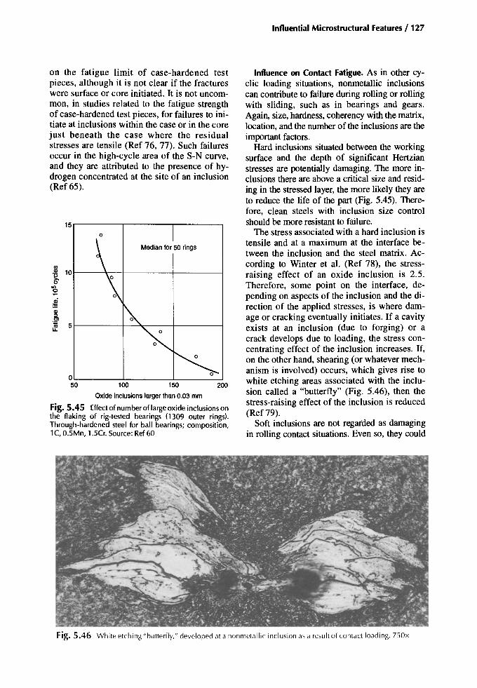
Influential Microstructural Features / 127
Influence on Contact Fatigue. As in other cyclic loading situations, nonmetallic inclusionscan contribute to failure during rolling or rollingwith sliding, such as in bearings and gears.Again, size, hardness, coherency with the matrix,location, and the number of the inclusions are theimportant factors.
Hard inclusions situated between the workingsurface and the depth of significant Hertzianstresses are potentially damaging. The more inclusions there are above a critical size and residing in the stressed layer, the more likely they areto reduce the life of the part (Fig. 5.45). Therefore, clean steels with inclusion size controlshould be more resistant to failure.
The stress associated with a hard inclusion istensile and at a maximum at the interface between the inclusion and the steel matrix. According to Winter et aI. (Ref 78), the stressraising effect of an oxide inclusion is 2.5.Therefore, some point on the interface, depending on aspects of the inclusion and the direction of the applied stresses , is where damage or cracking eventually initiates. If a cavityexists at an inclusion (due to forging) or acrack develops due to loading , the stress concentrating effect of the inclusion increases. If,on the other hand, shearing (or whatever mechanism is involved) occurs, which gives rise towhite etching areas associated with the inclusion called a "butterfly" (Fig. 5.46), then thestress-raising effect of the inclusion is reduced(Ref 79).
Soft inclusions are not regarded as damagingin rolling contact situations. Even so, they could
200150100
OL-- ----l --L _
50
150
Medianfor 50 rings
'"CD 10'U~
on0-cD==CD::IE'
~ 5
on the fatigue limit of case-hardened testpieces, although it is not clear if the fractureswere surface or core initiated. It is not uncommon, in studies related to the fatigue strengthof case-hardened test pieces, for failures to initiate at inclusions within the case or in the corejust beneath the case where the residualstresses are tensile (Ref 76, 77). Such failuresoccur in the high-cycle area of the S-N curve,and they are attributed to the presence of hydrogen concentrated at the site of an inclusion(Ref 65).
Oxideinclusionslarger than0.03 mm
Fig. 5.45 Effect of number of large oxide inclusionsonthe flaking of rig-tested bearings (1309 outer rings).Through-hardened steel for ball bearings; composition,1C, 0.5Mn, 1.5Cr. Source: Ref 60
Fig. 5.46 W hite etching "butterfly," developed at a nonmetall ic inclusion as a result of con tact loading. 750x

128 / Carburizing: Microstructures and Properties
have some effect if they lie in the zone of cyclicstress. Littman and Widner (Ref 79) state that inbearing fatigue tests, cracks and butterflies arealmost never associated with sulfide inclusions.Sugino et al. (Ref 80) confirm that MnS is fairlyharmless in this respect, but Al20 3 (with or without associated MnS) encourages the formation ofbutterflies (Table 5.12). Winter et al. (Ref 78),referring to gears, observed very small areas ofwhite etching material at sulfide inclusions butdid not associate them with contact failures.Consequently, soft inclusions are of less concernthan the harder types. Nevertheless, their size,type, and quantities are best controlled to improve other properties.
Influence on Impact Fracture Strength andToughness. The Charpy toughness (shelf energy)is increased by increasing the cleanness of a steel(Ref 81) or by reducing the average size of inclusions and the number of large inclusions. Thetransition temperature, on the other hand, is littleif at all affected by an increase of cleanness.
The toughness in the longitudinal direction isnot necessarily improved by increasing cleanness, but for each of the transverse directions, especially the through-thickness direction, toughness is improved (Ref 58,81).
Consequences of Producing Clean Steels
Machinability. The improvements to metalshaping machines and tools have not alwaysmatched the improvements in steel cleanness. Asa result, machining problems are encounteredwhen the sulfur content of a lean-alloy steel fallsbelow about 0.009%. Difficult machining canlead to poor workpiece surface finish and heavytool wear. Even when the sulfur content is above0.009%, the machinability can vary somewhatdepending on the size of the sulfide particles.Steels with larger particles tend to machine moreeasily than do those in which the sulfides aresmall.
Manganese sulfide is well known for its contributions to easy machining and good tool life.It assists in chip breaking of the swarf as it flowsfrom the cutting zone. It is not particularly abra-
sive to the flank of a tool, and it provides a protective layer on the rake face, which protectsagainst cratering.
The crystalline silicates and alumina (thenondeformable types) tend to give heavy toolwear and are not effective as chip breakers.Those silicates that become deformable at about850°C assist machinability when the cuttingspeed is sufficiently high to generate temperatures in excess of 850 °C in the swarf metal as itshears away from the rake face of the cuttingtool.
The ceramic and the coated tools developedfor clean steel machining might not be durablefor machining the less clean steels. Sulfide inclusions have the potential to chemically react withthe cutting surfaces of such materials, thereby increasing tool wear.
Overheating. The appearance of matte facetson the fracture faces of impact test pieces indicates that the steel has been "overheated" during the preheating and hot-working processes.The dissolution of manganese sulfide and itsreprecipitation as very fine particles on the austenite grain boundaries during hot working areregarded as the cause (Ref 58). Decreasing thesulfur content lowers the onset temperature foroverheating where the onset temperature is at itslowest when the sulfur content is between 0.002and 0.004%. The steel composition and thecooling rate from the working temperature havean effect on overheating. For example, nickellowers the overheating temperature, and coolingrates between 10 and 300 °C/min seem to produce more matte facets on the impact test fracture surfaces than other cooling rates (Ref 82).A reheat temperature of 1150 °C is consideredsafe, and in the event of overheating, a reheat to1200 °C reduces, if not eliminates, the effect.Thus, overheating is reversible. According toRef 59, RE or calcium modifications to a lowsulfur steel can prevent overheating by raisingthe overheating temperature.
McBride (Ref 82) asserts that severe overheating can reduce the fatigue resistance by 20 to
Table5.12 Listof inclusion type and occurrence associated with butterfly formation'IYpe of IIOIIIIIeIlIIIk indus;oo Appearance orooometallic inclusion Frequency or butterflies
MnS Elongated (<3 11m) RareElongated «311m) FewVerythin and long None
Finely dispersed stringers ManyNoneMany

25%. Gardiner (Ref 83) determined the bestcombination of preheating temperature andpercent metalworking reduction to maximizethe overheating effect of two VAR S82 casehardening steels. Using these conditions to induce overheating, test pieces were prepared (carburized and uncarburized) and tested. Overheating had no detrimental effect on:
• Rotating bending fatigue strength of eithercarburized and uncarburized samples
• Rate of crack growth in uncarburized samples• Fatigue crack initiation sites• Tensile strength• Fracture toughness
It did, however, reduce the tensile ductility, the impact toughness, and the KISCC•
Burning takes place at temperatures above-1450 °C and is irreversible. It is caused byliquation at grain boundaries, encouraged by thesegregation to the boundaries of solute elements, such as phosphorus and sulfur. When thesulfur content is high, the temperature for burning is not much above that for overheating.When the sulfur content is low, the overheatingtemperature is lowered, thereby increasing therange between the overheating and burningtemperatures.
Welding. It is not good practice to weld partsbefore or after carburizing and hardening. However, because cleanness affects the response of asteel to welding, the following information is included.
The use of cleaner steels significantly improves weldability. The risk of heat affected zone(HAZ) liquation cracking diminishes as the sulfur content is reduced, and lamellar tearing becomes less of a problem as the through- thickness ductility is improved as a result of steelcleanness.
However, clean steels are prone to HAZ cracking during and following the welding operation.This cracking occurs due to a high HAZhardenability, which results from the relative absence of sulfide and oxide inclusions. These inclusions, had they been present in quantity,would have stimulated the formation of HTIP(Ref 84). Instead, there is a greater tendency formartensite to form in the HAZ, which, coupledwith the intake of hydrogen into the zone (fromthe steel and from the welding), can result in hydrogen-induced HAZ cracking. Hewitt (Ref 85)reported a definite trend between hydrogencracking and sulfur content. Therefore, for clean
Influential Microstructural Features / 129
steels, a low-hydrogen welding practice is recommended.
Summary
Grain size
Grain size affects both case and core properties; small grain sizes are required.
• Preprocess considerations: Purchase steel ofappropriate quality; adhere to the grain-size:requirement. A normalizing heat treatment favors an initially uniform and small grain size.
• In-process considerations: High-temperaturecarburizing (>1000 "C) tends to encouragesome grain growth. Direct-quenched casestend to be coarse in terms of grain size,martensite plate size, and the size of austenitevolumes. Re-heat quenching favors a refinedstructure.
• Postprocess considerations: Consider reheatquenching, keeping in mind the distortion aspect. For some applications, shot peeningmight counter some of the adverse effects of acoarse-grained structure (although no data areavailable to show this).
• Effect on properties: A fine grain size can occasionally have an adverse influence on thecase and the core hardenability of lean-alloycarburizing steels. However, in general, a finegrain size is preferred. Coarse-grained steelsare thought to distort more during heat treatment. A coarse austenite grain will, whenquenched, produce large martensite plates andlarge austenite volumes. Large martensiteplates are more prone to microcracks than aresmall plates. Altogether, these adverse effectscontribute to reduced fatigue and impactstrengths.
• Standards: Specifications on grain size callfor a grain size of predominantly five or finer.
Microcracks
Microcracks refer to cracks that develop during the formation of plate martensite. They areconfined to the high-carbon regions of the case.Large high-carbon martensite plates are morelikely to have microcracks.
• Preprocess considerations: Plain-carbon andvery lean-alloy grades of steel are more proneto microcracking during case hardening.

130 / Carburizing: Microstructures and Properties
Therefore, the steel grade needs to be considered, as does grain size.
• In-process considerations: High carburizingtemperatures favor grain growth and, hence,coarse plate martensite. Microcracking tendency increases with carbon content; therefore, consider case carbon control. Directquenching retains more carbon in solution inthe martensite; therefore quenching methodand temperature are important.
• Postprocess considerations: Tempering is regarded as beneficial, and refrigeration mighthave a negative effect.
• Effecton properties: This is difficult to assess,though it is thought by some that fatiguestrength is reduced by as much as 20%.
• Standards: ANSIIAGMA has no specificationfor grades 1 and 2. For the grade 3 quality, 10microcracks in a 0.0001 in.2 (0.06 mm-) fieldat 400 is specified.
Microsegregation
Microsegregation is unavoidable; it is influenced by the modes of solidification duringcasting. The degree of microsegregation is affected by the alloy content of the steel, includingtramp elements. The distribution and directionality of microsegregation are affected bymetalworking processes, and its intensity can bereduced to some degree during the mechanicaland thermal treatments. Generally speaking,manufacturers and heat treaters have to live withmicrosegregation.
• Preprocess considerations: Microsegregationis difficult to assess during acceptance testing;it is often masked by interstitial elements, forexample, by carbon in normalized products. Itcan create machining problems.
• In-process considerations: Microsegregationcan cause severe cracking in the more alloyedcarburizing grades during slow cooling fromthe carburizing temperature. In carburizedand quenched surfaces, microsegregation cancause alternating zones of martensite and austenite, which are regarded as unsatisfactory. Itcan also influence the growth and distortionbehavior of a heat-treated part.
• Postprocess considerations: Where actual casehardened parts are not sectioned for qualityassessment, the presence of microsegregationand its effect on structure will go undetected.Its presence should be considered during service failure analyses.
• Effect on properties: See comments for "Inprocess factors" in this list. Microsegregation,along with nonmetallic inclusions, appreciably influences the transverse properties ofwrought steels, particularly the toughness andductility indicators. Austenite/martensite ormartensitelbainite banding, if either occur, isexpected to have a negative influence on fatigue resistance, especially in those surfacescontaining bands of bainite.
• Standards: No specifications
Nonmetallic Inclusions
All steels contain numerous nonmetallic inclusions, but the cleaner grades have fewer large orsignificant inclusions than do the conventionalgrades. Clean steels, however, are more prone tooverheating problems during forging.
• Preprocess considerations: Steel quality requirement, and the steel purchased, is determined by the product quality sought, for example, ANSIIAGMA 2001 grade 1,2,3, oraircraft quality. For special applications, ultrasonic surveys maybe carried out to determine if, and where, significant inclusions orinclusion clusters reside within the workpiece. Actions are taken accordingly. Cleansteels can be more difficult to machine thanconventionally melted steels.
• In-process considerations: No in-processconsiderations
• Postprocess considerations: Shot peening ofcritically stressed areas will, to some extent,offset any adverse effects of nonmetallics residing at, or close to, the surface of that area.
• Effect on properties: Nonmetallic inclusionscan have a significant adverse influence ontransverse toughness and ductility. In terms offatigue properties, soft inclusions are lessharmful than are hard inclusions, size for size.In case-hardened parts nonmetallics might notseriously affect the fatigue limit but couldcontribute to greater life variability at stressesabove the fatigue limit.
• Standards: For AGMA grade 2 and grade 3qualities, (ultrasonic and magnetic particlenondestructive testing) requirements are specified. Sulfur contents to 0.040% are permittedfor grade 2, and to 0.015%S for grade 3.
• Note: Magnetic particle examination may beneeded for detecting defects at or close to asteel surface; such defects are the more likelyto affect service life. In magnetic-particle ex-

amination of gear teeth larger than 10 pitchnormal diameter (p00)' indicationsof less thanY64 in. (-0.4 rom) are ignored, yet the criticaldefect size for case-hardened surfaces couldbe less than this. Therefore, while such inspectionsare important, they may not guarantee a freedom from harmful surface breakinginclusions.
REFERENCES
Grain Size
1.Nickel Low-Alloy Steels Case Hardening, International NickelLtd., 1968
2. MA Krishtal and S.N. Tsepov, Steel Pr0perties after High Temperature Vacuum Carburising, Metalloved. Term. Obrab. Met., Vol 6,June 1980,p 2-7
3. M.l Vinograd, lY. Ul'Yanina, and G.A.Faivilevich, Mechanism of Austenite GrainGrowth in Structural Steel, Met. Sci. HeatTreat., Vol 17 (No. 1-2), JanlFeb 1975
4. B.L. Biggs, Austenite Grain-Size Control ofMedium-Carbon and Carburising Steels, J.Iron Steel Inst., Vol 192 (No.4), Aug 1959,P361-377
5.0.0. Miller, Influence of Austenitizing Timeand Temperautre on Austenite Grain Size ofSteel,Trans. ASM, 1951,Vol 43, P 260-289
6.MA Grossman, Grain Size in Metals, withSpecialReferenceto GrainGrowthin Austenite, Grain-Size Symp., American Society forMetals, 1934,p 861-878
7. RG. Dressel, R Kohimann, KJ. Kremer, andA. Stanz, The Influence of Rolling and HeatTreatment Conditions on Austenitic GrainGrowth in Case Hardened Steels, Hart-Tech.Mitt., Vol 39 (No.3), May/June 1984, p112-119
8.VA Kukareko, The Regularities of AusteniteGrainGrowth in Steel 18KhNVA, Metalloved.Term. Obrab. Met., (No.9), Sept 1981,p 15-17
9. H. Child, Vacuum Carburising, Heat Treat.Met., Vol3, 1976,p 60-64
10.J.D. Murray, D.T. Llewellyn, and B. Butler,Development of Case Carburizing C-MnSteels, Low-Alloy Steels, lSI publication 114,The Iron and Steel Institute, 1968,p 37-53
11.L.N.Benitoand D. Mahrus, 35thAnnual Congress ofAssociation Brasileira de Metals, Vol1, Association Brasileirade Metals,July 1980
12.A. Randak and E. Kiderle, The Carburisationof Case-Hardening Steels in the TemperatureRange between 92~1100 °C (BISI 5231),
Influential Microstructural Features/ 131
Hart.-Tech. Mitt., Vol 21 (No.3), 1966,1~198
13.H. Dietrich, S.Engineer, andV. Schuller, Influences on the Austenitic Grain Size of CaseHardening Steels, Thyssen Edelstahl Tech.Ber., Vol 10 (No. I), July 1984,P 3-13
14. W.T. Cook, The Effect of Aluminum Treatmenton theCaseHardeningResponseof PlainCarbonSteels,Heat Treat. Met., 1984,(No. 1),P 21-23
15.V. Franciaet al., Effectof the PrincipalMetallurgicalParameters of Steelon Carburising andHardening, Metall. Ital., Vol74 (No. 12),Dec1982,P 851-857
16.P.M. Kelly and J. Nutting, StrengtheningMechanisms in Martensite, MG/Conf/85/65, p166-170
17.MA Zaecone, J.B. Kelley, and G. Krauss,Strain Hardening and Fatigue of SimulatedCase Microstructures in Carburised Steels,Conf Proc. Processing and Performance(Lakewood, CO),ASMInternational, July1989
18.K. Onel and J. Nutting, Structure-PropertiesRelationship in Quenchedand Tempered Carbon Steel,Met. SeL, Oct 1979,P 573-579
19.RWK. Honeycombe, Steels-Microstructures and Properties, EdwardArnold, 1982
20.P.Schane, Effectsof McQuaid-Ehn Grain-Sizeon the Structure and Properties of Steel,Grain-Size Symp., American Society forMetals, 1934,p 1038-1050
21.E. Macherauch, Das ErmudungsverhaltenMetallischer Werkstoffe, Hart.-Tech. Mitt., Vol22 (No.2), 1967,P 103-115
22.V.D. Kat'ner, V.F. Nikonov, and SA Yurasov,Modem Carburizing and Carbonitriding Techniques, Met. Sci. Heat Treat., Vol 15 (No.9),Sept 1973,p 752-755
23.J.L. Pacheco and G. Krauss, Microstructureand High BendingFatigueStrength in Carburised Steel,J. Heat Treat; Vol 7 (No.2), 1989
24. H. Brugger, Werkstoff und Warmebehandlungseinflusse auf die Zahnfubtragfahigkeit,VDI Berichte, (No. 195), 1973,P 135-144
25. H.-J. Kim and Y.-G. Kweon, High-Cycle Fatigue Behavior of Case-Carburized MediumCarbon Cr-Mo Steel, Metall. Mater. Trans. A,Vol 27, 1996,P 2557-2564
26.G. Krauss,The Microstructure and Fractureofa Carburised Steel, Metall. Trans. A, Vol 9,Nov 1978,P 1527-1535
27.GZ. Wang and J.H. Chen, A Comparison ofFracture Behaviour of Low Alloy Steel with

132 /Carburburizing: Microstructures and Properties
Different Sizes of Carbide Particles, Metall.Mater. Trans. A, Vol 27, July 1996
28. K. Isokawa and K. Namiki, Effect of AlloyingElements on the Toughness of CarburisedSteels, DenkiSeiko(Electr. Fum. Steel), Vol57(No. I), Jan 1986, p 4-12
29.1.1. Prokof'eva, M.V. Taratorina, and LV.Shennazan, Effect of Martensite Needle Sizeon the Mechanical Properties of Steel 45 afterInduction Hardening, Metalloved. Term.Obrab. Met., (No. 10), ocr 1978, P 10-13
Microcracking
30. RP. Brobst and G. Krauss, The Effect of Austenite Grain Size on Microcracking inMartensite of an Fe-1.22C Alloy, Metall.Trans., Vol 5, Feb 1974, p 457-462
31. A.R. Marder and A.D. Benscoter,Microcracking in Fe-C Acicular Martensite,Trans. ASM, Vol 61, 1968, P 293-299
32. AH. Rauch and WR Thurtle, Microcracks inCase Hardened Steel, Met. Prog., Vol 69 (No.4), April 1956, P 73-78
33. M.G. Mendiratta, 1. Sasser, and G. Krauss, Effect of Dissoved Carbon on Microcracking inMartensite of an Fe-1.39C Alloy, Metall.Trans., Vo13, Jan 1972, p 351-353
34. RG. Davies and C.L. McGee, Microcrackingin Ferrous Martensites, Metall. Trans., Vol 3,Jan 1972, p 307-313
35. RF. Kern, Controlling Carburising for TopQuality Gears, GearTechnol., MarlApril 1993,p 16-21
36. L. Jena and P. Heich, Microcracks in Carburised and Hardened Steel, Metall. Trans., Feb1972, Vol 3, p 588-590
37. AR Marder, AD. Benscoter, and G. Krauss,Microcracking Sensitivity in Fe-C PlateMartensite, Metall. Trans., Vol 1, June 1970, p1545-1549
38. 1. Hewitt, The Study of Hydrogen in Low-Alloy Steels by Internal Friction Techniques, Hydrogen in Steel, Special report 73, The Iron andSteel Institute, 1962, P 83-89
39. RG. Baker and F. Watkinson, The Effect ofHydrogen on the Welding of Low-AlloySteels, Hydrogen in Steel, Special report 73,The Iron and Steel Institute, 1962, p 123-132
4O.A.R. Marder and A.D. Benscoter,Microcracking in Plate Martensite of AISI52100 Steel, Metall. Trans., Vol 1, Nov 1970, P3234-3237
41. A.R. Marder and A.D. Benscoter,Microcracking in Tempered Plate Martensite,
Metall. Trans., Vol 5, Mar 1974, p 778-78142. T.A. Balliett and G. Krauss, The Effect of the
First and Second Stages of Tempering onMicrocracking in Martensite of an Fe-1.22CAlloy, Metall. Trans. A, Vol 7, Jan 1976, p81-86
43. C.A Apple and G. Krauss, Microcracking andFatigue in a Carburized Steel, Metall. Trans.,May 1973, Vol 4, p 1195-1200
44. M.A. Panhans and RA Fournelle, High CycleFatigue Resistance of AISI 9310 CarburisedSteel with Different Levels of Surface Retained Austenite and Surface Residual Stress,1. HeatTreat., VoI2(No.1),June 1981,p54-61
45. R.F. Kern, Carburize Hardening: DirectQuench vs. Reheat and Quench, J. HeatTreat.,March 1988, p 17-21
46. 1. Lyman, High Carbon Steel MicrocrackingControl during Hardening, J. Eng. Mater.Techrwl. (Trans. ASME), Vol 106, July 1984, p253-256
47. I. Laren and H. Fredriksson, Relations betweenIngot Size and Microsegregation, Scand. J.Metall., Vol 1, 1972, p 59--68
Microsegregation
48. T.B. Smith, Microsegregation in Low-AlloySteels,/ronSteel,Vol37,Nov 1964,p536-541
49.1. Philibert, E. Weinry, and M. Ancey, A Quantitative Study of Dendritic Segregation inIron-Base Alloys with the Electron-ProbeMicroanalyser, Metallurgia, Vol 72 (No. 422),Nov 1965, P 203-211
50. T.B. Smith, 1.S. Thomas, and R. Goodall,Banding in a 1Y2% Nickel-ChromiumMolybdenum Steel, 1. Iron SteelInst., Vol 201,July 1963, P 602--609
51. RG. Ward, Effect of Annealing on the Dendritic Segregation of Manganese in Steel, J.IronSteelInst., Vol203, Sept 1965, p 930-932
52. A Kulrnburg and K. Swoboda, Influence ofMicro-Segregations on the Transformation Behaviour and Structural Constitution of AlloySteels,Prakt. Metallogr., Vol6, 1%9, P 383-400
53. M. Kroneis et al., BergHiittenmann. Montash.,Vol 113, 1968, p 416-425
54. M. Kroneis et. al., Properties ofLarge Forgingsof Electroslag Remelted Ingots, 5th Int.Forging Conj (6-9 May 1970),Temi,p 711-737
Nonmetallic Inclusions
55. R Kiessling, Nonmetallic Inclusions in SteelIV, Metals Society, 1978; R Kiessling, Nonmetallic Inclusions in Steel II, Metals Society,

197856.1. Watanabe, Some Observations on the Effect
of Inclusions on the Fatigue Properties ofSteels, Proc. 3rd Japanese Congo of TestingMaterials, Kyoto University, 1960,p 5-8
57.E. Plockinger,Properties of Special Constructional Steels Manufactured by SpecialMelting Processes Including Steels forForging, Stahl Eisen, Vol 92 (No. 20), 1972,P 972-981
58. WT. Cook and D. Dulieu, Effect of Cleanerson Properties of Heat-Treated MediumCarbon and Low-AlloySteels,Heat Treatment'87 (London), Instituteof Metals, 1987
59. WR McFarland and 1.T. Cronn, Spheroidisation of Type IT Manganese Sulfide by HeatTreatment, Metall. Trans. A, Vol 12 (No.5),May 1981,p 915-917
60. R Kiessling, Nonmetallic Inclusions in SteelIll, Metals Society, 1978
61. S.I. Gubenko, Phase Transformations in Nonmetallic Inclusions during Heat Treatment ofSteels,Izv. V.U.Z ChernayaMetall., (No. 12),1986,P 67-71
62. S.I. Gubenko, Dissolution of Nonmetallic Inclusions during High Temperature Heating,Izv. Akad.Nauk SSSR,Met., (No.2), Mar/April1983,p 103-107
63. W.A.Spitzig and RJ. Sober, Influenceof Sulfide Inclusionsand PearliteContenton theMechanical Properties of Hot-Rolled CarbonSteel, Metall. Trans. A, Vol 12, Feb 1981, p281-291
64. G.E. Dieter, Mechanical Metallurgy, Metallurgy and Metallurgical Engineering Series,McGraW-Hill, 1961,p 270-271
65. G. Kiessling, NonmetallicInclusions in Steel V,Metals Society, 1989
66. D. Brooksbankand K W Andrews,Productionand Application of Clean Steels, J Iron SteelInst., Vol210, 1972,p 246-255
67. KB. Grove and J.A. Charles, Further Aspectsof InclusionDeformation,Met. Technol., Vol 1(No.9), Sept 1974,p425-431
68. RN. Cummings, EB. Stulen, and We. Schulte,Tentative Fatigue Strength Reduction Facors forSilicate-Type Inclusions in High-Strength Steels,Proc. ASTM, \b158, 1958, P 505-514
69. T. Ohta and K Okamoto, Effectof Nonmetallic Inclusions on Fatigue Life of BearingSteels, Tetsu-to-Hagane (J Iron Steel Inst.),Vol52, 11, Lecture 104,230, 1966
70. T. Tsunoda, I. Uchiyama,and T.Araki,Fatigue(of Steels) in Relation to the Non-Metallic In-
Influential Microstructural Features / 133
elusion Content, Tetsu-to- Hagane (J IronSteel lnst.), Vol52, 11,Lecture229,103,1966
71. YE. Goldstein, A.Y. Zaslavskii, and B.S.Starokozhev, Effect of Lead on the FatigueCharacteristics of Structural Steels, Metal Sci.Heat Treat., 5 May 1973,p 397
72. WE. Duckworth and E. Ineson, Clean Steels,Special report 77, The Iron and Steel Institute,1963,p 87-103
73. Y. Kawada, H. Nakazawa, and S. Kodama,Mem. Fac. Technol., Tokyo Metrop. Univ., (No.15), 1965,P 1163-1176
74. RE Kern, Selecting Steels for Heat-TreatedParts,Met. Prog., Vol 94 (No.5), Nov 1968,P60-73
75. L.O. Uhrus, Clean Steels, Special report 77,The Iron and Steel Institute, 1963,p 104-109
76. E Vodopivec and L. Kosec, The FatigueStrength and the Influence of Nonmetallic Inclusions on the Fatigue Fracture ofCase-Hardening Steels(BISI5906),Hart. -Tech.Mitt., Vol 22, July 1967,P 166-173
77. S.Gunnarson,StructureAnomaliesin the Surface Zone of Gas-Carburized, Case-HardenedSteel, Met. Treat. Drop Forging, June 1963, p219-229
78. R Winter, G. Knauer, and 1.1. Gamel, WhiteEtching Areas in Case Hardened Gears, GearTechnol., Sept/Oct 1989,p 18-44
79. WE. Littmanand RL. Widner,PropagationofContact Fatigue from Surface and Sub- Surface Origins, Trans. ASME, Sept 1966, p624--636
80. K Suginoet aI.,StructuralAlterationsof Bearing Steels under Rolling Contact, Trans. lSI],Vol 10, 1970,P 98-111
81.G.R Speich and W.A. Spitzig, Effect of Volume Fraction and Shape of Sulfide Inclusionson Through-Thickness Ductility and ImpactEnergy of High-Strength 4340 Plate Steel,Metall. Trans. A, Vol 13, Dec 1982, p2239-2259
82.1.S. McBride, Overheating-Reappraisal of aReccurring Problem, Met. Mater., Vol 8 (No.5), May 1974,p 269-270
83.RW Gardiner, Effect of Overheating on theFatigue Strength and Other MechanicalProperties of Carburized and UncarburizedVAR S 82 Steel, Met. Technol., Dec 1977,p536-547
84.P.Hart, Effectsof Steel Inclusions and ResidualElements on Weldability, Met. Constr., Oct 1986
85.1. Hewitt, Hydrogen in Steel, B.I.S.R.A.ffheIron and Steel Institute, 1961
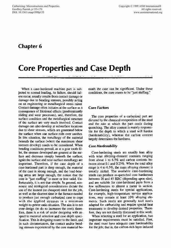
Chapter 6
Core Properties and Case Depth
When a case-hardened machine part is subjected to normal loading, its failure, should failure occur, usually results from contact damage ordamage due to bending stresses, possibly actingon an engineering or metallurgical stress raiser.Contact damage often initiates at the surface as aconsequence of frictional effects (predominantlysliding and wear processes), and, therefore, thesurface condition and the metallurgical structureof the surface are very much involved. Contactdamage can also develop at subsurface locationsdue to shear stresses, which are generated belowthe surface when one surface rolls over another.In this situation, the metallurgy of the materialbeneath the surface (where the maximum shearstresses develop) needs to be considered. Whenbending conditions prevail, as at a gear tooth fillet, the stresses developed are greatest at the surface and decrease steeply beneath the surface;again the surface and near-surface metallurgy areimportant. Therefore, if the case depth of acase-hardened part is deep enough, the materialof the case is strong enough, and the load-bearing areas are large enough, the notion that thecore is 'just stuffing" is more or less valid. Unfortunately, it is not that simple. In general, economic and ecological considerations dictate theuse of the leanest (or cheapest) steel for the job,as well as the shortest time in the furnace neededto produce just enough carburized case to copewith the applied stresses in a minimumweight-to-power ratio situation. The aim is to notover design (to do so increases the cost); therefore, there is a risk of under designing with respect to material selection and case depth specification. This is designing nearer to the limit, andin such circumstances, the contact and/or bending stresses experienced by the core material be-
neath the case can be significant. Under theseconditions, the core ceases to be 'just stuffing."
Core Factors
The core properties of a carburized part aredictated by the chemical composition of the steeland the rate at which the part cools duringquenching. The alloy content is mainly responsible for the depth to which a steel will harden(hardenability), whereas the carbon contentlargely determines the hardness.
Core Hardenability
Case-hardening steels are usually lean alloywith total alloying-element contents rangingfrom about 1 to 6.5% and carbon contents between about 0.1 and 0.25%. When the total alloyrange is 4 to 6.5%, the main alloying element isusually nickel. The available case-hardeningsteels can produce as-quenched core hardnessesbetween 20 and 45 HRC (depending upon size),and are suitable for case-hardened parts from afew millimeters to almost a meter in section.Case-hardening steels for special applications,for example, high-temperature service applications, may contain at least 10% alloying elements. Such steels are generally tool steelsadapted for carburizing and require special heattreatments to develop desired properties. Therefore, they are not directly discussed in this work.
When selecting a steel for an application, twoimportant requirements must be satisfied. First,the steel must have adequate case hardenabilityfor the job; that is, the carbon-rich layer induced
Carburizing: Microstructures and Properties Copyright © 1999 ASM International® Geoffrey Parrish, p 135-170 All rights reserved. DOI: 10.1361/cmap1999p135 www.asminternational.org

136 / Carburizing: Microstructures and Properties
by carburizing will suitably harden whenquenched. A number of steels might satisfy thisrequirement, but each will likely have a differentcore hardness range. Therefore, the second requirement to be satisfied is core hardness (orstrength) of the critical core areas of the component. This primarily relates to the hardeningdepth (the core-hardenability). Figure 6.1 provides a general view of core hardenability interms of how average tensile strength varies withsection size and alloy content.
Microstructures observed within the cores ofcase-hardened parts are: ferrite (undissolved orprecipitated), bainite (upper and lower), andmartensite (low-carbon) (see Fig. 6.2). Pearlite isnot found in a quenched core material unless the
section size is large and the steel has lowhardenability. In such an instance, the case mightnot satisfactorily harden. One reason ferritecould be present in an as-quenched core materialis that it was austenitized (prior to quenching) ata temperature below the AC3 temperature, leaving some ferrite undissolved. Another reason,perhaps the most common, is that a steel is employed that has less hardenability than requiredfor the section. This is illustrated in Fig. 6.3where the upper continuous-cooling transformation (CCT) diagram represents a lean-alloycase-hardening steel, and the lower diagramrepresents a medium-alloy case-hardening steel.By superimposing near-surface cooling curves(e.g., for -12 mm and -50 mm diameter bars),
10
820M 17
Tolerance ±10 tsi
822 M 17
4 6Equivalent diameter, in.
I I50 100 150 200 250
Equivalent diameter, mm
Diameter, in.12346816
659 M 15
835 M 15
832 M 13
Tolerance ±7 tsi
4 6Equivalent diameter, in.
I I ~I--IL...-*"".......~b-.......~;;-.......~~~~50 100 150 200 250 0
Equivalent diameter, mm
Io
1391
1236
773 50
8!. 1082:::iii
~cl!!U; 927
618
Steel
835M 15659MI5832M 13655M13655M 17822M 17820M 17815MI7637M17635MI5
Nominal composition, \I>
C Mn Ni Cr Mo
0.15 0.40 4.1 1.1 0.200.15 0.40 4.1 1.10.13 0.40 3.2 0.90 0.20
0.13 0.50 3.2 0.900.17 0.50 1.8 0.25
0.17 0.60 2.0 1.5 0.200.17 0.80 1.8 1.0 0.15
0.17 0.80 1.4 1.0 0.150.17 0.80 1.0 0.80 0.050.15 0.80 0.80 0.60 0.05
Fig. 6.1 Strength versus section diameter for a number of U.K. carburizing steels. Use lower scale to estimate bar center strength; use upper scale to estimate bar surface strength. Source: Ref 1

Core Properties and Case Depth / 137
lime, S
it is seen that for such conditions, the formationof ferrite is unavoidable in the leaner gradebut avoidable in the more alloyed grade. Consequently, if ferrite is not desired in the core of apart, an adequately aIIoyed steel must beselectedwith quenching from the fully austenitic condition. Increasing the cooling rate might suppressferrite formation up to a point. The selection of aborderline grade of steel might, on abatch-to-batch basis, lead to a fair amount ofcore structure variability. This is becausesteelmakers cannot work to precise chemicalcompositions; they must have reasonable working tolerances. In the unlikely situations whereeach alloying element in a steel is either at thebottom or at the top of its specification range, thetransformation characteristics can be extremelyvariable, as Fig. 6.4(a) and (b) suggest. Evenvariations of carbon content alone can make adifference in transformation behavior (Fig.6.4c). This indicates for this steel that if thecarbon content is low at 0.08%, the time to theferrite nose is less than 8 s, which means, for
105
(e)
8oor-~-........::---~--------,
700
o 600
i SOO.a 400 I:=-==-=,,=~aslii 300~ 200 h¥iiwJ-4-.../{!!.100
o-looL..-_--l..__...J....__l--_--l..__-l-J
1 10
(a)
1()2Time,s
lime, S10
10
C 0.12%....... 51 0.20"10
" -, --- Mn 0.50%
'" ............... F Ni 3.20%Cr 0.85%
M \.1"8 <, - Mo 0.12%
\ "r-
\-;2m~mm-dia~_diambar bar
~ ........ .......F
~-" SOmmM /"8 \. ~Jdiam C 0.17%
~ "- bar - 5i 0.30%
"\12 mm~Mn 0.800/0diam - Ni 0.50%bar_I------ Cr 0.50"10
Mo 0.20%
900
800
700~~ 600
~ 500~400Ef'!.300
200
100
o1
900
800
700~~600.a 500l!!~400E~300
200
100
o1
(a)
(b)
Fig. 6.3 Acomparison of the continuous-cooling transformation diagrams for (a) BS 970 805M20 (SAE 8620)(composition: 0.17 C, 0.30 st. 0.80 Mn, 0.50 Ni, 0.50 o.0.20 Mo) and (b) BS970 832M13 (composition: 0 .12 C,0.20 Si, 0.50 Mn, 3.20 Ni, 0.85 Cr, 0.12 Mol. F, ferrite; B,bainite, M, martensite. Surface cooling is shown for a 12mm diam bar and a 50 mm diam bar.
(b)
(c)
Fig. 6.2 Microstructures obtained by cooling a 0.16%C3%Ni-Cr steel from 920°C. (a) Fast cool (920-200 °C in 30s) giving low-carbon martensitic structure of 1590 MPaUTS. 800x. (b) Intermediate cool (920-250 °C in 200 s) giving bainitic structure of 1360 MPa UTS. 800x. (e) Slow cool(920-250 OC in 10" s) giving a ferrite/pearlite structure of740 MPa UTS. 800><. Source: Ref1

138 / Carburizing: Microstructures and Properties
(e)Tirne.s
as-quenched core strength of less than about1000 MPa (145 ksi). With this in mind, one cancarburize, slow cool, and subcritical anneal to facilitate the removal of areas of the case where,after quenching, further machining operationscan be performed.
105
103
102 103Time, S
102 103
Time,s
10
10
10
......
'\ <:..,--
\ -
" I
1000r---------------,
900
800
~ 700
f!! 600:::J
~ 500
~ 400~~~~1I=w.~-.....__
~ 300
200.~~E.",-100O~--_ _'_ _'~ ____'____'
1
10001==============1900
o 800f-:=~;::===========l0_ 7001-l!! 600~ 5008. 400'---E300
{Eo 200100
o......---:':---~;;---~;;--~.-----:7.1
(b)
(8)
Fig. 6.4 Continuous-cooling trans~ormation diagra~sfor selected 3%Ni-Cr case-hardening steels. Specification En 36 is now replaced by 655M13 and 831M13.(a) Ni, Cr, and Mo contents all atthe bottom of the specification range (En 36). Composition: 0.12 C, 0.20 Si, 0.40Mn, 3.00 Ni, 0.60 Cr, 0.00 Mo, 0.00 V. (b) Ni, Cr,and Mocontents all at the top of the specification range. Composition: 0.12 C, 0.20 Si, 0.60 Mn, 3.50 Nil 1.10 Cr, 0.25Mo, 0.00 V. (c) Effectof carbon content with alloying elements at constant levels. Composition: 0.06-0.18 C, 0.20Si, 0.54 Mn, 3.18 Ni, 0.91 Cr, 0.04 MOl 0.00 V.Source:Ref1
1000900
u 8000_ 700~ 600~ soo8. 400E 300
{Eo 200100
o1
example, that an oil-quenched 12.5 mm (Yz in)diameter bar will contain some ferrite at its center. When the carbon content is raised to 0.18%and the other elements remain the same, the timeto the ferrite nose is nearer to 200 s. This allowsa 125 mm (5 in.) diameter bar to be oil quenchedwithout any ferrite production. Fortunately, steelmanufacturers can generally maintain theamount of each element in a steel grade withinnarrow limits. The purchase of controlledhardenability steels also makes for a greater degreeof consistency from batch to batch. In termsof end-quench hardenability, Fig. 6.5(a) and (b)show the hardenability curves that correspond tothe CCT curves of Fig. 6.3; the extremes of thebands of Fig. 6.5(b) correspond to the CCTcurves of Fig. 6.4(a) and (b).
There are areas within the core of a carburized and hardened component that experiencelittle, if any, stress during service; for these areas, the microstructure and strength are of littleconcern. It is those areas just beneath the casewhere high stresses develop during service forwhich core structure and strength are important.Therefore, when using CCT diagrams to assessthe suitability of a steel for a given component,the near-surface cooling rate is the most meaningful.
Ferrite cores, although not uncommon, are often regarded as unacceptable for critically loadedcomponents. Bainite-type cores are perhapsmore common and more desirable than ferrite.The martensitic, or predominantly martensitic,core structures tend to be found in those components with small sections, and these are also desirable if the core carbon and the core hardnessare not too high.
In selecting a steel for a particular component,care must be taken to choose one without toomuch carbon and hardenability for the shape andthe section involved, otherwise growth, distortion, and internal cracking (as under the tops ofgear teeth) might become a problem. Also, oneneeds to decide whether to choose a steel of reasonable hardenability and harden it with a mildquench, or to adopt a lower hardenability steeland hard quench it. The choice between a lowhardenability steel with a high carbon content,and a higher hardenability steel with a low carbon content often depends on the duty of the finished item. However, a low hardenability steelwith a high carbon content is more prone to sizevariations. One good reason for selecting an alloy case-hardening steel with a low nominal carbon content (-0.13%) is that it should develop an

8 10 12 14 16 18 20 22 24 26 28 30 32
Distance from quenched end,1/16in.
642
Diameters of rounds with Location in round Quenchsameas-qllenched hardness (HRC), in.
2 4 Surface Mild1 2 3 4 :Y4radius from center water
0.5 1 1.5 2 2.5 3 3.5 4 center quench
1 2 ~ 4 Surface Mild0.5 1 1.5 2 2.5 3 3.5 4 :Y4radius fromcenter oil
0.5 1 1.5 2 2.5 3 3.5 Center quench
SAEIAISI8620H UNS H86200
Heat-treating temperatures recommended by SAENormalize(for forgedor rolledspecimensonly):925°C (1700oF)
"I\.Austenitlze: 925°C (1700oF)
\,\ -,
\ -,\ I'---.r----, -
20o
25
55
30
65
35
60
50
(8)
65
60
55
50
~:I: 45
~1l 40:I:
35
30
25
Diameters of roundswith Location in round Quenchsameas·quenched hardness (HRC), in.
2 4 Surface Mild1 2 3 4 3/4 radiusfromcenter water
0.5 1 1.5 2 2.5 3 3.5 4 Center quench
1 2 3 4 Surface Mild0.5 1 1.5 2 2.5 3 3.5 4 3/4 radiusfromcenter oil
0.5 1 1.5 2 2.5 3 3.5 center quench
SAEIAISI9310H UNS H93100
Heat-treating temperatures recommended by SAENormalize(for forgedor rolled specimensonly):925 OC (1700 oF)Austenitize: 845°C (1550 oF)
-r--'- r--"'--- -<,<,
......r--r--
20o 2 4 6 8 10 12 14 16 18 20 22 24 26 28 30 32
Distance fromquenched end,1/16in.(b)
Fig. 6.5 Hardenabilityrangesfortwo case-hardeninggradesofsteel.Source:Ref2
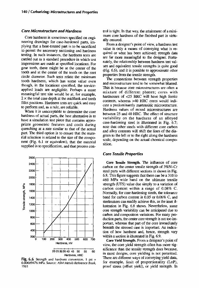
140 / Carburizing: Microstructures and Properties
Core Microstructure and Hardness
Core hardness is sometimes specified on engineering drawings for case-hardened parts, implying that a heat-treated part is to be sacrificedto permit the necessary sectioning and hardnesstesting. In such instances, the hardness tests arecarried out as a standard procedure in which testimpressions are made at specified locations. Forgear teeth, these might be at the center of thetooth and at the center of the tooth on the rootcircle diameter. Such tests relate the minimumtooth hardness, which has some value eventhough, in the locations specified, the serviceapplied loads are negligible. Perhaps a moremeaningful test site would be at, for example,2 x the total case depth at the midflank and toothfillet positions. Hardness tests are quick and easyto perform and, as a rule, are reliable.
When it is unacceptable to determine the corehardness of actual parts, the best alternative is tohave a simulation test piece that contains appropriate geometric features and cools duringquenching at a rate similar to that of the actualpart. The third option is to ensure that the material selection is related to the size of the component (Fig. 6.1 or equivalent), that the materialsupplied is to specification, and that process con-
trol is tight. In that way, the attainment of a minimum core hardness of the finished part is virtually ensured.
From a designer's point of view, a hardness testvalue is only a means of conveying what is required or what has been achieved; strength dataare far more meaningful to the designer. Fortunately, the relationship between hardness .testvalues and equivalent tensile strengths is quite good(Fig. 6.6), and it is possible to approximate otherproperties from the tensile strength. .
The connections between strength propertiesand microstructure tend to be somewhat blurred.This is because core microstructures are often amixture of different phases; cores withhardnesses of <25 HRC will have high ferritecontents, whereas >40 HRC cores would indicate a predominantly martensitic microstructure.Hardness values of mixed microstructures arebetween 25 and 40 HRC. The effect of structurevariability on the hardness of an alloyedcase-hardening steel is illustrated in Fig. 6.7;note that other steels with different core carbonand alloy contents will shift the lines of the diagram to the left or to the right along ~e hardnessscale, depending on the actual cherrucal composition.
Core Tensile Properties
Core Tensile Strength. The influence of corecarbon on the center tensile strength of 3%Ni-Crsteel parts with different sections is shown in Fig.6.8. This figure suggests that there can be a 310 to460 MPa wide band on the ultimate tensilestrength (UTS) value due simply to a variation ofcarbon content within a range of 0.08% C.Normally, for case-hardening steels, the toleranceband for carbon content is 0.05 or 0.06% C, andsteelmakerscan readily achieve this, as the inset illustration in Fig. 6.8 shows. Nevertheless, somecore strength variability can be anticipated due tocarbon and composition variations. For many production parts, the center core strength is not too important, whereas that part of the core irnm~a~ly
beneath the stressed case is important. An indication of how hardness and, hence, strength varywithin a section is illustratedin Fig. 6.9.
Core Yield Strength. From a designer's point.ofview, the core yield strength often has more Significance than the tensile strength does because,in most designs, core yielding is not permitted.There are different ways of conveying yield data,for example, limit of proportionality (LoP),proof stress (offset yield), or yield strength. In
L
L
/
LV
//
V/
v0
1000
1200
1400
~ 1800::i:s:: 1600e;,c:
~Q)
~c:{!:.
800
2600
600
2000
2200
2400
400
20 0 100 200 300 400 500 600 700
Hardness, HV
I I I I I I I I I20 253035 40 45 50 55 60
Hardness, HRC
Fig.6.6 Strength and hardness conversion. 1 psi =0.00689476 MPa. Source: ASM Metals Reference Book,1981
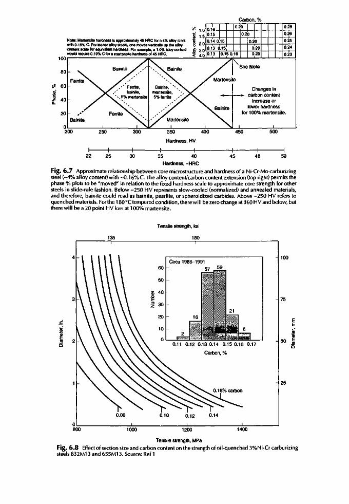
0.28
0.26
0.25
0.24
0.23
500450
Changes in__-I~_ carbon content
increase orlowerhardness
for 100% martensite.
400
oJ!. 1.0 0.16-+-+-+---1-l-+--+-+-+--+~-+E 1.50.15~ Fr--+-++-+:':;:-+-If-t-+-+~---l8 2.0 0.140.15
1;' 3.0 0.13 0.15
::e 4.0 0.13
350
NotII:Martensite hardness is approximately 45 HACfora 4%alloysteelwi1h 0.16%C. Forleaneralloysteels, onemoves vertically up thealloycontentscale for equivalent hardness. Forexample, a 1.0%alloycontenlwouldrequire 0.19%C fora martenstte hardness of45 HRC.
100r----------~.-----------''-''':::.L....J-...l...-.,,~L......J----I.--L--'----'--'-__'__i
80
~ 60ojen«l 40s:Q.
20Bainite
0200 250
Hardness, HV
I I I I I I I22 25 30 35 40 45 48 50
Hardness, -HRC
Fig. 6.7 Approximate relationship between core microstructure and hardness of a Ni-Cr-Mo carburizingsteel (-4% alloy content) with -0.16% C. The alloy content/carbon content extension (top right) permits thephase % plots to be "moved" in relation to the fixed hardness scale to approximate core strength for othersteels in slide-rule fashion. Below -250 HV represents slow-cooled (normalized) and annealed materials,and therefore, bainite could read as bainite, pearlite, or spheroidized carbides. Above -250 HV refers toquenched materials. For the 180°C tempered condition, there will be zero change at 360 HVand below, butthere will be a 20 point HV loss at 100% martensite.
Tensilestrength, ksi
135 180
25
100
60 59
50
Q; 40.0E 75:::> 30z
20.5 E
E~ 10 iCD GiE 0 50 E«l
0.11 0.12 0.13 0.14 0.150.16 0.17 «l0 0Carbon, %
0.08 0.10 0.12 0.14
14001200goo=-=---------:-1-:l000=------~:l:-:-------~:-------I
Tensilestrength, MPa
Fig. 6.8 Effectof section size and carbon content on the strength of oil-quenched 3%Ni-Cr carburizingsteels 832M13 and 655M13. Source: Ref 1
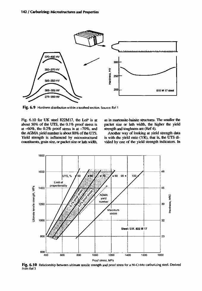
142 / Carburizing: Microstructures and Properties
~ < , .[/ 300
200 815 M17steel
Fig. 6.9 Hardness distribution within a toothed section. Source: Ref 1
Fig. 6.10 for UK steel 822M17, the LoP is atabout 50% of the UTS, the 0.1% proof stress isat -60%, the 0.2% proof stress is at -70%, andtheAGMA yield number is about 80% of theUTS.Yield strength is influenced by microstructuralconstituents,grainsize, or packet size or lath width,
as in martensite-bainite structures. The smaller thepacket size or lath width, the higher the yieldstrength and toughness are (Ref 4).
Another way of looking at yield strength datais with the yield ratio (YR), that is, the UTS divided by one of the yield strength indicators. In
1800 ,.-------,-----,.----,------,.-------,-----,.------,
1600 49
Limit of
'" 1400proportionality
45a..:::;;
~ oc: a:e J:til <Ii.!!l 1200 39 '".,'<;; c:c: "E.!!l '"*
J:
E
5 1000 32
Steel: U.K. 822 M 17
800 23
18001600140012001000800600600 '--__--'- --'- ...L- L-__--'- --'-__---'
400
Proofstress, MPa
Fig. 6.10 Relationship between ultimate tensile strength and proof stress for a Ni-Cr-Mo carburizing steel. Derivedfrom Ref3

Core Properties and Case Depth / 143
195 225 255 285 315165
- 0 .nImpacl
M",,Ir-
~o Reduction of area
0
~ ~'"<, 8- •~~
~ _ 0
v IA-.", :_~Elongation I<Y • ,-'"
"1f'I-
245
Proof stress'w.><
vi1Il
!!! 190u;
~ oO.2%Ca. _0.3%C
",0.5%C
135
;§ 20.
Core Ductility. The ductility indicators are thepercent reduction of area and the percent elongation as derived from the tensile test; the higherthe values of the two indicators, the more ductilethe metal is. Ductility relates to the ability of amaterial to be plastically deformed without fracture; it is important to those who work metals,for example, wire manufacturers or car-bodypress shop operators. For case-hardened parts,the significance of core ductility is not at all clearbecause the applied stresses must exceed the engineering yield strength of the core before ductility becomes a consideration. Nevertheless, acceptance testing for case-hardening steelsrequires that the percent reduction of area, thepercent elongation, and the impact resistance aredetermined, if only to assure the manufacturerthat the steel is of acceptable quality. Accordingto the trend, as the strength and hardenability ofthe steel increase, the ductility decreases (Fig.6.12).
Tensile strength. ksi
Fig. 6.12 Mechanical properties of lightly temperedplain-carbon martensites to illustrate how ductility fallsas strength rises. Source: Ref 7
;fl. 30
.~n 20::>c
10
Core Toughness
Toughness is the ability of a metal to absorbenergy. This is generally important with respectto case-hardened parts because tough casehardened parts are more able to survive occasional
40
°
I225 48
'w200 ~ 44.5
i5> oc: 0::
175 ~ 39 :::cu; I
Q) vi150 '1jj 33
1IlQ)
c: c:.l!J "E
125 -@ 26 ell:::cE
100 :52.0
Ratio of ultimate tensile stress to 0.2% proof stress
Fig. 6.11 Relationship between the ultimate tensilestrength and the 0.2% proof stress (offsetyield) of carburizing steels (0.08-D.18% C), Note that with carbon contents of over 0.18%, the ratio can be as low as 1.15 forstrengths over about 200 ksi (44 HRCl. Data from Ref3
Strainsoftening StrainI hardening
1600&. 1500 f---f-
:2 1400 f---t~ 1300 f---f-
~ 1200 f---f-
~ 1100 1--1----'~ 1000 1---+
.l!J 900 f---t--'-@ 800 I-----t--+---',§ 700I-----t--+--I---1---=I5 600 L..----'_---'_--'-_--'-_-'
1.0 1.2 1.4 1.6 1.8
Fig. 6.11, the yield ratio =UTS/0.2% proofstress. This illustration represents bars of 1X in.diameter with carbon contents up to 0.18%, andshows that for core strengths typical ofmartensitic and/or bainitic microstructures, theYR is fairly low (around 1.3 to 1.5); that is, theyield strength is fairly high. With smaller sectionsizes and carbon contents above 0.18%, yield ratios down to 1.15 are possible. Core materialscontaining ferrite tend to have low yieldstrengths and high yield ratios (1.5 to more than2.0); how high depends on the amount of ferritepresent. (The significance of a fairly high-yieldstrength core material will become more apparent when fatigue resistance is considered.) Interestingly, regarding straining in tension, if theyield ratio is more than 1.4, work hardening willoccur during cyclic straining. If, on the otherhand, the ratio is less than 1.2, work softeningwill occur during cyclic straining. Between 1.2and 1.4, the material is probably fairly stable(RefS).
The yielding referred to so far is macroyieldingas determined during a typical tensile test. However, before that stage is reached, microplasticyielding has already commenced at a much lowerstress. The onset of microplastic yielding, the trueelastic limit, is when dislocation migration firstoccurs, and can be measured by determining thechange of AC resistance while straining in uniaxial tension (Ref 6). Tests on samples of athrough-hardened and low-temperature temperedcase-hardening steel have indicated that the trueelastic limit is only a few percent below the bending fatigue limit.

144 / Carburizing: Microstructures and Properties
overloads and cyclic impact loading than areparts of relatively low toughness.
Tests for toughness include notched (severeto gentle notches) and unnotched impact bendtests, notched and unnotched slow bend tests,and precracked fracture tests. Such tests indicate the contributions of alloying elements,microstructure, and hardness to fracture resistance. The more meaningful information is obtained not from the standard impact tests(Charpy and Izod) but from those tests in whichthe stress raiser in the test piece is more similarto those found in actual machine components.Chesters examined the limitations of the standard impact test in an early work (Ref 8). Theresults of this research for a number of steelsare summarized in Fig. 6.13. The standard teston its own did not supply much information onthe effect of material composition on impact,whereas the simulated gear tooth did. Further,even with Izod impact test values below 10ft . lb, the case-hardening grade of steel (En 36)still offered a good resistance to impact whenthe stress concentrator was similar to that for asmall gear tooth. The use of the notched impact
test has largely been driven by the nationalstandards, and its value, if any, is regarding material acceptance. Even used for that purpose, anotched impact value of 20 ft . lb (27 1) is considered ample for most applications, though theappropriate material standard might call formore than 27J (Ref 9). Another limitation of thestandard test is that the results do not relate to fatigue performance, nor can they be used in design formulas. The more recently adopted instrumented impact and bend tests used for researchprojects, while still having some limitations, employ test pieces that contain more realistic stressconcentrators; therefore, these tests more usefully contribute to the understanding of the respective influences of steel composition, coremicrostructure, and hardness (strength).
Fett showed that steels containing little or nonickel are notch sensitive at core hardnesses of>40 HRC in slow bending, and sensitive at >30HRC under impact loading (Ref 10). Nickelsteels (>1.8% Ni) are not so sensitive at thatvalue, which means that with the nickel grades ofcase-hardening steels one can develop ahigh-yield strength core that is adequately tough.
lzod, J
100
80
..,cCDE
60 '0
0 ~0ClIQ.
.EOJ
40 '0aen
20
l'lOmm2 ,I
Positionof blow
f-~~r---+---+ Medium carbon -+-----=::-+---+--=001.-.=:.----t---'------i
800r---....,..;::.-,---;;----r...::;::::-,----:;:i----r--T=---,----T.,-----,
60
;e.<= 50CCDE'0a 40en0ClIQ.
.5jg 30oaen
20 o Ni• Medium carbon.. En 19
10A En 36o En 29• En 30
30o°O!----:l=--~:I=---::!~---!:---==-----:!::---:::.::----=--~--7,loo40 50
lzod, It ·Ibf
Fig. 6.13 Comparison between standard impact test results and results from a test piece designed to simulate a geartooth. En 19, 705M40 (nominally, OAOC, 1.0Cr, 0.3 Mo); En36, 832M13 (nominally, 0.13 C, 3.2 Ni, 1.0Cr,0.15 Mo); En30, 835M30 (nominally, 0.30 C, 4.0 Ni, 1.2 o.0.3 Mo); En29, 722 M24 (nominally 0.24 C, 3.0 o.0.5 Mol. Source: Ref8
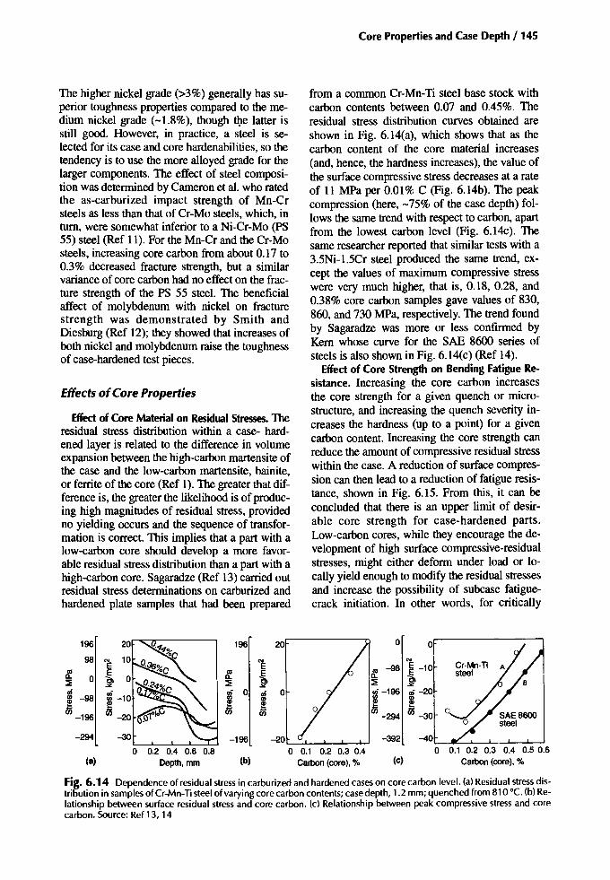
Core Properties and Case Depth / 145
The higher nickel grade (>3%) generally has superior toughness properties compared to the medium nickel grade (-1.8%), though the latter isstill good. However, in practice, a steel is selected for its case and core hardenabilities, so thetendency is to use the more alloyed grade for thelarger components. The effect of steel composition was determined by Cameron et al. who ratedthe as-carburized impact strength of Mn-Crsteels as less than that of Cr-Mo steels, which, intum, were somewhat inferior to a Ni-Cr-Mo (pS55) steel (Ref 11). For the Mn-Cr and the Cr-Mosteels, increasing core carbon from about 0.17 to0.3% decreased fracture strength, but a similarvariance of core carbon had no effect on the fracture strength of the PS 55 steel. The beneficialaffect of molybdenum with nickel on fracturestrength was demonstrated by Smith andDiesburg (Ref 12); they showed that increases ofboth nickel and molybdenum raise the toughnessof case-hardened test pieces.
Effects ofCore Properties
Effect of Core Material on Residual Stresses. Theresidual stress distribution within a case- hardened layer is related to the difference in volumeexpansion between the high-carbon martensite ofthe case and the low-carbon martensite, bainite,or ferrite of the core (Ref 1). The greater that difference is, the greater the likelihood is of producing high magnitudes of residual stress, providedno yielding occurs and the sequence of transformation is correct. This implies that a part with alow-carbon core should develop a more favorable residual stress distribution than a part with ahigh-carbon core. Sagaradze (Ref 13) carried outresidual stress determinations on carburized andhardened plate samples that had been prepared
from a common Cr-Mn-TI steel base stock withcarbon contents between 0.07 and 0.45%. Theresidual stress distribution curves obtained areshown in Fig. 6.14(a), which shows that as thecarbon content of the core material increases(and, hence, the hardness increases), the value ofthe surface compressive stress decreases at a rateof 11 MPa per 0.01% C (Fig. 6.14b). The peakcompression (here, -75% of the case depth) follows the same trend with respect to carbon, apartfrom the lowest carbon level (Fig. 6.14c). Thesame researcher reported that similar tests with a3.5Ni-1.5Cr steel produced the same trend, except the values of maximum compressive stresswere very much higher, that is, 0.18, 0.28, and0.38% core carbon samples gave values of 830,860, and 730 MPa, respectively. The trend foundby Sagaradze was more or less confirmed byKern whose curve for the SAE 8600 series ofsteels is also shown in Fig. 6.14(c) (Ref 14).
Effect of Core Strength on Bending Fatigue Resistance. Increasing the core carbon increasesthe core strength for a given quench or microstructure, and increasing the quench severity increases the hardness (up to a point) for a givencarbon content. Increasing the core strength canreduce the amount of compressive residual stresswithin the case. A reduction of surface compression can then lead to a reduction of fatigue resistance, shown in Fig. 6.15. From this, it can beconcluded that there is an upper limit of desirable core strength for case-hardened parts.Low-carbon cores, while they encourage the development of high surface compressive-residualstresses, might either deform under load or locally yield enough to modify the residual stressesand increase the possibility of subcase fatiguecrack initiation. In other words, for critically
196 196 20 0 0
98 '" '" l-1OlE E -98 Cr-Mn-Ti A~ E ~ ~ ~ steel::! 0 ~ ::! ::! ~-"ui ~ 0 ui 0 ~-196 ui -20III -98 III !~ ~ ~ ~en en -294 en -30 0
-196
-294 -30 -196 -20 -392 -40l...-~---L_I.--~.......J.---J
o 0.2 0.4 0.6 0.8 0 0.1 0.2 0.3 0.4 0 0.1 0.2 0.3 0.4 0.5 0.6(a) Depth,mm (b) carbon (core), % (c) Carbon (core), %
Fig. 6.14 Dependence of residual stress in carburized and hardened cases on core carbon level. (a) Residual stress distribution in samples of Cr-Mn-Tisteel of varying core carbon contents; case depth, 1.2 mm; quenched from 810 0c. (b) Relationship between surface residual stress and core carbon. (c) Relationship between peak compressive stress and corecarbon. Source: Ref13, 14
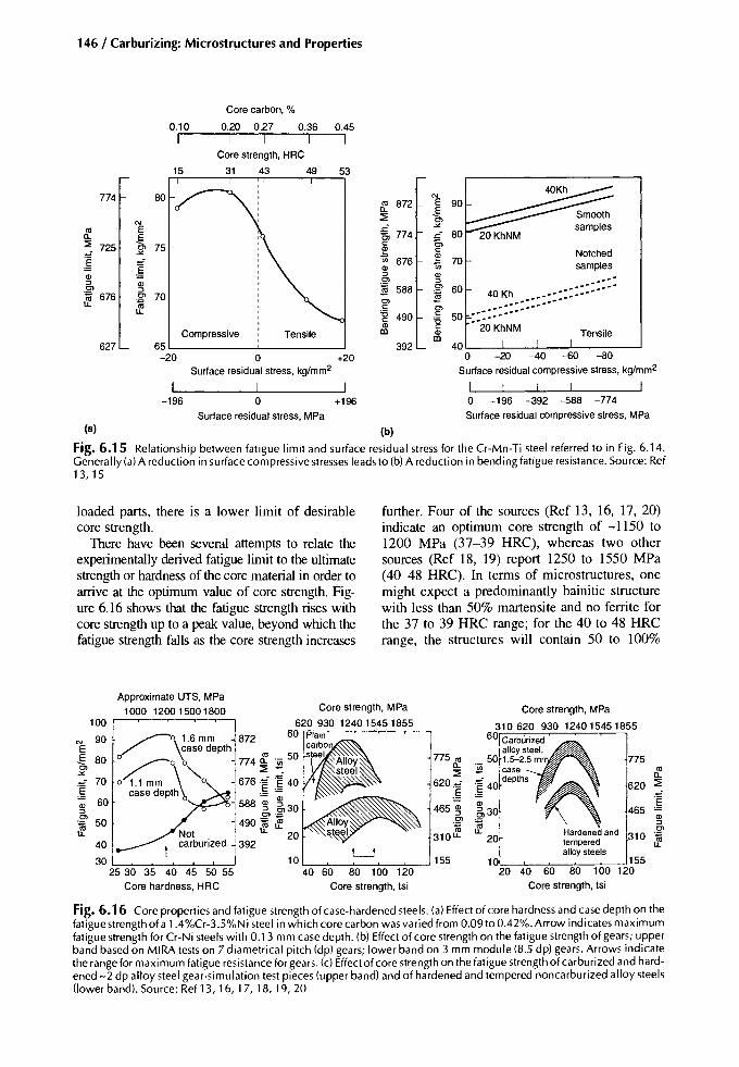
146/ Carburizing: Microstructures and Properties
Tensile
Notchedsamples
40 '---.1-:,-----'---:'-:---.1-:,-----'o -20 -40 --60 -80Surface residual compressivestress, kg/mm2
I Io -196 -392 -588 -774Surface residual compressivestress, MPa
70
60..'
40 Kh•••••• ::: •••...... ............... ............... .. ............ ......
50 ..."20 KhNM
Core carbon, %
0.10 0.20 0.27 0.36 0.45I I I I I
Core strength, HRC
15 31 43 49 53
774 N
'" 872 E0.. -§,
N~
'" E ~ 774-"
0..
~ t~ 725 c~ c
~Vi 676
OJ
~ OJ 1;;OJ :::l OJ:::l OJ
Ol :::lOl :::l $ 588 Ol
~ 676 Ol ~LL ~ OlC OlLL '6 cc 490 '6OJ c
Compressive Tensile CD OJCD
627 65 392-20 0 +20
Surface residual stress, kg/mm2
I I I-196 0 +196
Surface residual stress, MPa
00 ~
Fig. 6.15 Relationship between fatigue limit and surface residual stress for the Cr-Mn-Ti steel referred to in Fig. 6.14.Generally (a) A reduction in surface compressive stresses leads to (b) A reduction in bending fatigue resistance. Source: Ref13,lS
loaded parts, there is a lower limit of desirablecore strength.
There have been several attempts to relate theexperimentally derived fatigue limit to the ultimatestrength or hardness of the core material in order toarrive at the optimum value of core strength. Figure 6.16 shows that the fatigue strength rises withcore strength up to a peak value, beyond which thefatigue strength falls as the core strength increases
further. Four of the sources (Ref 13, 16, 17, 20)indicate an optimum core strength of -1150 to1200 MPa (37-39 HRC), whereas two othersources (Ref 18, 19) report 1250 to 1550 MPa(40-48 HRC). In terms of microstructures, onemight expect a predominantly bainitic structurewith less than 50% martensite and no ferrite forthe 37 to 39 HRC range; for the 40 to 48 HRCrange, the structures will contain 50 to 100%
465
775
OJ:::l
Hardened and 310 Ol
tempered :falloy steels
10 15520 40 60 80 100 120
Core strength, tsi
Core strength, MPa
310 620 930 12401545185560 Carburized
alloysteel.50 1.5-2.5 m
"l§ case __~ 40 depths
OJ
5 30
:f20
775",0..~
620~
~465 ~
Ol
~310u..
10 155':c40;;---C6~0;----;;8~0---:1-::oo::-:-:12:-:0:--'
Core strength, tsl
Core strength, MPa
62093012401545185560 ..
Approximate UTS, MPa1000 1200 15001800
~o 1.6m~872/ _ \ case depth '"
~\ 7740.. ._50co! :::E ~
~'" I . ~o 1.1 mm 0"1 676 .-:: 'E 40case depth 0 i,§ ~
1 588 ~ 530i en·-
-1 490 ~ tfNot . LL 20carburized 139240
302'-::5"'-3""0""--::3">:5---:4~0-45.L-5....J0'--:-55-'
Core hardness, HRC
100
N 90E-§, 80-"
70~OJ 60:::lOl:f 50
Fig. 6.16 Core properties and fatigue strength of case-hardened steels. (a) Effect of core hardness and case depth on thefatigue strength of a 1.4%Cr-3.5%Ni steel in which core carbon was varied from 0.09 to 0.42%. Arrow indicates maximumfatigue strength for Cr-Ni steels with 0.13 mm case depth. (b) Effect of core strength on the fatigue strength of gears; upperband based on MIRA tests on 7 diametrical pitch (dp) gears; lower band on 3 mm module (8.5 dp) gears. Arrows indicatethe range for maximum fatigue resistance for gears. (c) Effect of core strength on the fatigue strength of carburized and hardened -2 dp alloy steel gear-simulation test pieces (upper band) and of hardened and tempered noncarburized alloy steels(lower band). Source: Ref 13,16, 17, 18, 19, 20

Core Properties and Case Depth / 147
Table6.1 Effect of quenching temperature on fatiguestrengthQuenching Surface hardness, Corehardness, Case depth 10500 HV Faliguelimiltemperature,oC HV HV mm 0.001 in. MPa ksi
760 780 235 0.425 17 610 88810 895 325 0.825 33 745 108840 925-940 400 0.875-0.925 35-37 8OD-91 0 116--132870 880 405 1.0 40 840 122900 915 410 0.825 33 880 128
Testsconductedon 637 M 17(l.07%Ni-0.88%Cr) 7dp (diametralpitch)gearspack carburizedat 900 "C for 7 h at a carbonpotentialof 1.1% singlequenched and not tempered.Source:Ref 22
martensite, again with no ferrite. Consideringtoughness, hardness values in excess of 40 HRCtend to be a little high, particularly for steelgrades containing little or no nickel. The determination of the optimum core strength is not unreasonable; useful information is thereby provided. It is, however, unreasonable to expect thechosen optimum strength to be achieved on acommercial basis, except by chance. A wider,more achievable range is needed in practice, forinstance, 1000 to 1300 MPa (32-42 HRC); inaddition, ferrite must be avoided. These considerations, however, apply only to the criticallyloaded areas. As Kal'ner et al. related, it is undesirable for the tooth core and the main body of agear to have the same strength because such asituation favors distortion (Ref 21). These researchers recommended that tooth cores have ahardness in the range 30 to 40 HRC, whereas thepreferred hardness for the gear body is between25 and 35 HRC. Developing a core hardnessrange of 30 to 40 HRC or 32 to 42 HRC immediately beneath the case ensures a more predictablelocal yield ratio (Fig. 6.11). That is, the yieldstrength will be fairly high to resist yielding andresidual stress fade due to cyclic stressing.
Whereas core hardness is influenced by thechemical composition of the steel, it is also affected by the quenching temperature, as is thesurface hardness. Consequently, the bending fatigue strength is also affected, as Table 6.1shows for a small untempered 637Ml7 automotive gear (Ref 22). This table illustrates howquenching from above the AC3 of the core is important for good bending fatigue strength; inpractice, however, the higher fatigue strengthmight not be realized if the growth and distortionare excessive due to quenching from a temperature that is too high.
Effect of Core Material on Impact-Fatigue Resistance. Undissolved ferrite in the cores ofcase-hardened notched test pieces significantlyreduces their impact-fatigue resistance (Fig.6.17). The difference in life between cores withferrite (low hardness) and those without (highhardness) is entirely due to crack propagation(Fig. 6.18). In the low-cycle regime, core carboncontent was significant: a core of 0.16% C required about 400 impacts to induce failure,whereas a core with 0.24% C failed in only 100impacts (Ref 24).
1180
1080
980
11.::E 880gf~ 780Ul
680
590
120Test pieces 9 mm diameter
110 '~12""N3A at root of 60' angle
" 81D-820'CV notches
100\ (40-42 HRC)
12KhN3A
~ "\ 760-770 'C Notch depth =0.25 mm\ \ (25-27 HRC)
~90 \ \ -. Uk =3.4\ \ Case depth =1.0-1.1 mm
20 Kh \ \<Ii , ,'" 80 83D-840 -c~, 20 Khe
US (32-34 HRC) , ,Notch depth =1.5 mm
\,
70 765-775 -c --', ''---- Uk =4.5
(25-27 HRC) , Case depth =0.5-0.6 mm60 '------
490 50 L...,__--'- '--__-l
103 104 105 106Cycles
Fig. 6.17 Impact-fatigue strength of carburized test pieces. First quench was from 900-920 °C followed by temperingat 640-660 °C with final quenching from the temperatures indicated. Test pieces were tempered at 170°C prior to testing. Core strengths are also indicated. Source: Ref 23
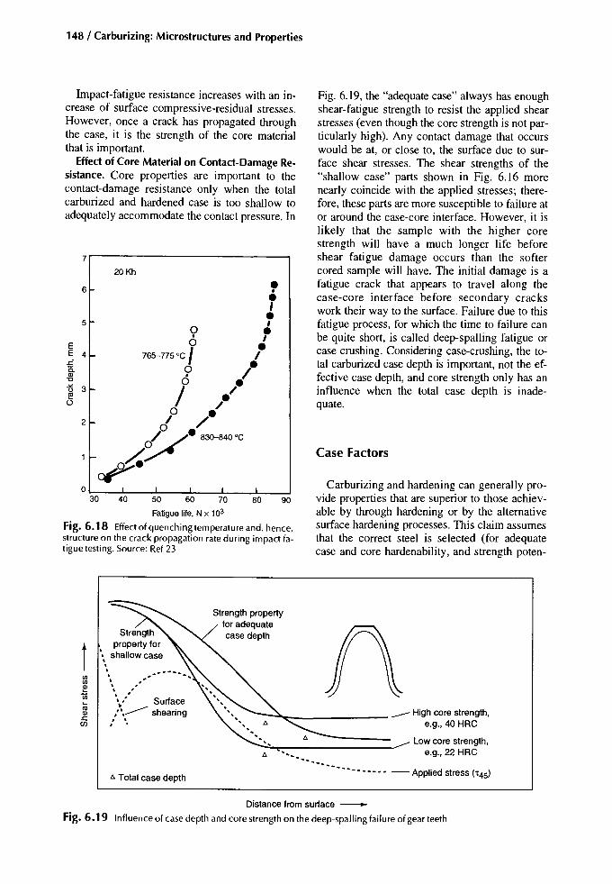
148 / Carburizing: Microstructures and Properties
Impact-fatigue resistance increases with an increase of surface compressive-residual stresses.However, once a crack has propagated throughthe case, it is the strength of the core materialthat is important.
Effect of Core Material on Contact-Damage Resistance. Core properties are important to thecontact-damage resistance only when the totalcarburized and hardened case is too shallow toadequately accommodate the contact pressure. In
7r-----------------,20 Kh
6
5
EE 4-
2
o I I
30 40 50 60 70 80 90
Fatigue life,N x 103
Fig. 6.18 Effect of quenching temperature and, hence,structure on the crack propagation rate during impact fatigue testing. Source: Ref 23
Fig. 6.19, the "adequate case" always has enoughshear-fatigue strength to resist the applied shearstresses (even though the core strength is not particularly high). Any contact damage that occurswould be at, or close to, the surface due to surface shear stresses. The shear strengths of the"shallow case" parts shown in Fig. 6.16 morenearly coincide with the applied stresses; therefore, these parts are more susceptible to failure ator around the case-core interface. However, it islikely that the sample with the higher corestrength will have a much longer life beforeshear fatigue damage occurs than the softercored sample will have. The initial damage is afatigue crack that appears to travel along thecase-core interface before secondary crackswork their way to the surface. Failure due to thisfatigue process, for which the time to failure canbe quite short, is called deep-spalling fatigue orcase crushing. Considering case-crushing, the total carburized case depth is important, not the effective case depth, and core strength only has aninfluence when the total case depth is inadequate.
Case Factors
Carburizing and hardening can generally provide properties that are superior to those achievable by through hardening or by the alternativesurface hardening processes. This claim assumesthat the correct steel is selected (for adequatecase and core hardenability, and strength poten-
t\\\,
\
"" """\,,' Surfacer.>: shearing, \, .
A Total case depth
~......~ High core strength,e.g., 40 HRC
Low core strength,'" e.g., 22 HRC
'" '"'. - •••••••• - Applied stress ('t45)
Distance from surface -----
Fig. 6.19 Influence of case depth and core strength on the deep-spalling failure of gear teeth

tial), and the carburizing and hardening processes are correctly executed so that the surfacecarbon content and the case depth are adequatefor the intended application.
Case Hardenability
The effect of carbon on the core transformation characteristics of a 3%Ni-Cr steel is depicted in Fig. 6.4(c), which shows that relativelysmall increases of carbon content significantlyincrease the hardenability. This trend continuesat still higher carbon levels, as illustrated in Fig.6.20, for a 1.3%Ni-Cr steel. In this example, thecase of a carburized and quenched 50 mm (2 in.)diameter bar will be martensitic for all carboncontents above about 0.5%.
Some time ago, an attempt was made to categorize the levels of case hardenability (Ref 1):
• Level 4: A martensitic case occurs at all carbon levels, including the core material justbeneath the case.
• Level 3: All carbon contents from the surfacedown to 0.27% C are martensitic.
• Level 2: All carbon contents from the surfacedown to 0.50% C are martensitic.
1000
Core Properties and Case Depth / 149
• Level J: Surface carbon contents of above0.80% are martensitic.
The respective case hardenabilities of a number of carburizing steels are compared in Fig.6.21. This figure shows that level 4 tends to beattainable only in small sections of the more alloyed steels, whereas level 3 is more readily attained in most of the steels listed, depending onthe section size. Level 2 is typical of manycase-hardened parts and should be attempted as aminimum. When a steel is selected for a givencomponent, the equivalent diameter for the critically stressed location is estimated. Then, from achart such as Fig. 6.21, the expected level of casehardenability can be assessed.
When dealing with surface carbon contentsand case hardenability, there is a carbon content(usually in the range 0.7--0.9%) for each steelabove which the bainite nose time starts to decrease (i.e., the case-hardenability begins to fall)(Fig. 6.22). This means that a surface with a carbon content over about 1.0% could containsome bainite, whereas just beneath the surfacewhere the carbon content is, for example, 0.9%,the microstructure consists of martensite and
800
~
\!f:0
l'! 600Q)c.Et!!!
400Ms (0.23 C)Ms (0.5 C)
Mf (0.15 C)200
Mf(0.23C)Mf(0.5C)
0 Mf (0.8C)
10 102
128 in.diam
105
Time,s
Fig. 6.20 Surface cooling rates for a number of bar diameters superimposed on the continuous-cooling diagrams for thecarbon levels of the core: 0.15, 0.23, 0.5, and 0.8%. Basesteel 815A16 austenitized at 830 °C for 100 minutes. Composition: 0.67 Mn, 0.90 o. 0.12 Mo, 1.32 Ni, 0.00 Si, 0.000 P, 0.000 S. Source: Ref 1

150 / Carburizing: Microstructures and Properties
Time to cool from 830-400 °C at Olin below the surface s Practical minimum composition, %
Direct quench20 MoCr4SAE 8620
SCR2215 NCD 2
En 34SMC 21
En 352SAE882216 MnCr5S NCM2210CND6
En 35320 NiMoCr6
En 354
Reheat quench
S NCM22En 353
20 NiMoCr6En 354
En36A18 CrNi8En36C
EX 36En 39 B
10 20 50 100 200 300 350 C Mn Cr Mo Ni
G • 0 0.19 0.57 0.47 0.4 0.7U.::;. • 0 +0.5%C andabovetransforms to martensite
0.18 0.68 0.42 0.2 0.45
• 0 0.19 0.66 0.97 )(0 )(0r) t 0 o 0.8%C and abovetransforms to martensite 0.14 0.75 0.45 0.17 0.47.K. , 0 0. Couldbe moretransformation 0.15 0.45 )(0 0.22 1.62
'", 0 0.14 0.66 0.97 0.17 )(0
.K. '" • o '" 027% C andabovetransforms to rnartensit 0.15 0.67 0.7 )(0 0.95
.::;. '" • 0 '" Coretransforms to martensite 0.2 0.79 0.42 0.32 0.45
'" t 0 0.15 0.07 0.87 )(0 )(0
'" • 0- 0.13 0.47 0.46 0.2 1.7r '" t 0- 0.1 0.43 1.3 0.19 0.9
U. '" + 0- 0- 0.15 0.67 0.9 0.12 1.32
'" '" • 0- 0.19 0.57 0.45 0.45 1.47
'" '" t 0- 0.15 0.67 0.9 0.12 1.57
J '", 0 0.13 0.47 0.46 0.2 1.7
U.K. '" t 0- 0.15 0.67 0.9 0.12 1.32G '"
, 0 0.19 0.57 0.45 0.45 1.47U.K. '" t 0- 0.15 0.67 0.9 0.12 1.57U.K. '" t 0- 0.11 0.41 0.77 )(0 3.19G '" '" + 0- 0.16 0.45 1.87 )(0 1.87U.K. '" • 0- 0.11 0.41 0.77 0.14 3.19U.S.) '" '" ~ 0.1 0.77 0.5 0.69 1.73I.K.!, '" '" ~ 0.13 0.31 0.92 0.19 4.0
0.2 0.5 2 5 10 20 50 100
Bar diameter, in.
Fig. 6.21 Case hardenabilities of a number of carburizing steels with oil quenching. Source: Ref 1
1.2
1.1
1.0
0.9
0.8
If. 0.7
C 0.60-e 0.5'"0
0.4
austenite but no bainite. Surfaces with bainitehave inferior contact fatigue properties compared to those without bainite. The bainite referred to here is not associated with decarburization or internal oxidation; it is a transformationcharacteristic, and is possibly related to carbideprecipitation. One should also bear in mind thatsome bainite may be produced by austenite decomposition during low-temperature tempering.
Time for austenitized bars to coolto 400-450 °C bainite nose temperature
12.5 mm 50 mm 100 mm
0.3 F----::7"'''-----::Y'';,.....~~=--
0.2 ~I =-~1 Mo L-__:...J
1 10 102 103
Time to bainite nose during CCT, s
Fig. 6.22 Examples of how carbon influences the timeto the bainite nose during continuous cooling. Differentsteels have different bainite nose temperatures within the400-450 °C range. Derived from Ref 25
Optimizing the surface carbon content for anyproperty requirement is only one consideration;it is also essential to have the right case depthand quenching conditions. That said, it is apparent that one surface carbon content cannot be theoptimum for all loading situations; some components, such as gears, at times experience toothbending with intermittent overloading, slidingcontact and wear, and rolling contact. Therefore,if a high carbon content is necessary, the possibility of bainite formation at the higher carbonlevels must be considered.
The "time to bainite nose" curves in Fig. 6.22are additionally useful because they indicate thecarbon content deep within the case at whichbainite begins to appear in the microstructure.For example, for the 20MoCr4 steel depicted inthe figure, a carburized part cooling at a rateequivalent to a 12.5 mm diameter bar will havesome bainite in its outer case when the carbonthere exceeds about 1%; the part will begin toshow bainite in its lower case where the carboncontent falls to about 0.47%. As the carbon content falls below 0.47%, the microstructure willcontain increasing amounts of bainite.
Case Carbon Content
The total carbon penetration depth reached at agiven carburizing temperature is determined bythe duration of active carburizing. In single-stage

Core Properties and Case Depth / 151
carburizing at a constant gas composiuon, thesurface carbon content is also influenced by theduration of active carburizing as Fig. 6.23 illustrates. Here the surface carbon content builds upwith time so that for a given case depth, the carbon potential must be adjusted to achieve a specified surface carbon content. With two-stage(boost-diffuse) carburizing, the required surfacecarbon is more readily achieved, provided a reasonable minimum case-depth is exceeded. During the first stage, a high carbon potential drivescarbon into the steel quickly, whereas in the second stage, when the carbon potential is lower,carbon diffuses outward and inward until equilibrium is reached with the furnace atmosphere,and the carbon gradient into the surface has theright shape (Fig. 6.24).
In developing a carbon gradient to obtain aspecific case depth, an addition to the case depthmust be made to account for any post-heattreatment grinding. Furthermore, the surface carbon content may need adjustment so that aftergrinding, the as-ground surface has the desiredcarbon content. The boost-diffuse method of carburizing is perhaps the best suited for that because it has the potential to produce a highcarbon plateau can potentially be at the surface.
Commercial carburizing has produced partswith surface carbon contents between 0.6 and1.2%, and more than 1.2% where wear resistanceis the prime requirement. The most commonrange, however, is 0.75 to 0.95%. The choice oftarget surface carbon should be determined bythe alloy content because, in general, an increase
of alloy content reduces the eutectoid carboncontent, the ACcm phase boundary is shifted tolower carbon levels, and the M, temperature isreduced. Hence, the more alloyed a steel is, thelower the target surface carbon content should beto prevent the formation of carbides or the excessive retention of austenite. In production "jobbing" heat-treating, the frequent adjustment ofcarbon potential to suit alloy grade, case depth,or application of the treated parts can createproblems, and the use of a standard high carbonpotential might be necessary, irrespective of theother considerations.
Effect of Case Carbon on Surface Hardness.Heat treaters aim to produce parts with finemartensitic surface structures and little or no freecarbide and without too much retained austenite.These parts should also have a reasonable levelof product consistency as indicated by workingto an as-quenched and tempered surface hardness within the 58 to 62 HRC range.
Most carburizing steels, in the fully martensitic condition, can attain 62 HRC (before tempering) with surface carbon contents as low as0.6%, though the potential maximum hardnessis achieved at still higher carbon levels, as shownin Fig. 6.25 (also see Fig. 4.11) (Ref 27). Themaximum hardness value attained by anyone ofthe steels shown probably equates to its eutectoidcarbon content. At higher surface carbon levels,the hardness achieved depends on the quenchingtemperature; the higher the quenching temperature is, the more likely retention of austenite, anda corresponding loss of hardness, will result.There are three trends of interest shown in Fig.6.25:
Depthbelow surface,mm
Fig. 6.23 Carbon profiles generated in single-stagecarburizing in times ranging from 1--48 h. Source: Ref 26
Carbon gradientat the end~ of the active carburizingstage
1.2.-----------------,
01L--J.._...l----J'---"-:--:-~_:_"::_~~~.....o 0.025 0.0500.075 0.100 0.125 0.150 0.175 0.200
Depth,cm
0.2
0.4
c:~ 0.6
'"o
Fig. 6.24 Carbon distributions with double-stage carburizing. Carbon gradient at the end of the active carburizing stage and the carbon gradient at the end of thediffusion stage are shown along with intermediate stagesof diffusion. Source: Ref 1
Steel:En 32Carburizingconditions:925°C inpropaneendothermicgas with0.2% CO2 (=0.8%carbon potential
0.8
0.7
0.6
0.5;,!10
c: 0.40-e'"o 0.3
0.2
0.1
00

152 / Carburizing: Microstructures and Properties
Carbon, %
Fig. 6.26 Charpy V notch toughness tests that relatehardness, carbon content, and toughness. Source: Ref28
Fig. 6.25 Effect of alloy and carbon contents on peakhardness for direct quenching. 0, the limits of carbon content between which 800 HV or more can be achieved.Data from Ref 27
5.0Peak
hardness, HV
0 18CrNi8
4.0
15CrNi6:fj
0.:::
~ 20NiCrMo6,;:,
3.0 E'E '"cl!! '"c 0 20MnCr5 E0o :::>>.
16MnCr5E
.Q2.0 'x« '"E
0 0 20MoCr4 a~0
1.000
1.00.80.60.40.2
......r---0 N OHRC
fo..
40HRC
"' .......
1\/50HRC-
~
~I5fHRC
oo
20
10
50
30
40
1.00.9
Carbon, %
0.7 0.80.6
• Carbon content for peak hardness value tendsto fall as alloy content increases.
• The value of peak hardness itself tends to riseas the alloy content falls.
• As the alloy content increases, the carbonrange for high hardness becomes smaller.
In practice in commercial carburizing, surface carbon contents are typically 0.1 to 0.2% higher thanthose for peak hardness (Fig. 6.25).
Effectof Case Carbon on Case Toughness. Testsused to measure or grade the steel toughnessusually involve either slow bending or impactbending. In each of these tests, the initial crackforms at the surface, and therefore, the conditionof the surface is important (but only in termsof crack initiation). Once a crack has started topropagate, the condition of the material and theresidual stresses ahead of the crack provide anyresistance to its development.
For virtually all applications involving casehardened parts, surface hardnesses in excess of58 HRC are essential. These values are achieved
with high surface carbon contents. Based uponnotched impact tests, high-carbon materials losetoughness at hardness levels above 40 HRC(Fig. 6.26); therefore, typical case-hardenedsurfaces have limited toughness (Ref 28). Forhigh-carbon materials typical of a case-hardened surface (0.7-1.0% C), the toughness tendsto decrease as the carbon content increases(Table 6.2) (Ref 29). Although lowering thesurface carbon content to -0.6% will improvethe apparent toughness, the initial crackstrength will be increased by increasing the corestrength (Ref 30). Using precracked impacttests, Smith and Diesburg (Ref 12) obtainedfracture toughness values of about 20 MPa.Jmfor high-carbon material close to the surface.As the carbon content decreased, these valuesincreased to about 50 to 90 MPa.Jm for materialat the case-core interface. The spread in toughness at the case-core interface is influencedby the alloy content and the residual stresses.On their own, the main alloying elements manganese, chromium, and nickel have a negative
Table 6.2 Effectof carbon content on '(Steel Carbon, % Hardness, HRC RA,%
PS-15PS-15PS-1548954870
0.990.860.720.950.70
60.060.560.555.557.0
3923164021
16.622.421.724.534.5
RA, retainedaustenite. Source:Ref 29

Core Properties and Case Depth / 153
1.5
105
Er-~...--_r----,-------j 1.25 ,;,
-",;,Ol
r------'l.~..._---t------j1.0 Q;cQ)
~
I-----+=~~~~k==_--j 0.75 U~t>
r-----+-----1'<.---'"-----j 0.5 ~
§
I---,-------+----t--------j 0.25
o Bending endurance limit1--'\--- • Static bending strength
" Impact bending strength.. Impact fracture energy
'"E~-"
""i5>ce1ii 250Olc'6cQ) 200tIl
150
1000
450,..------.-----,------, 1.75
Carburizing time, h
Fig. 6.27 Relation between carburizing time andbending strength. Source: Ref 32
Regardless of surface carbon, it is important toensure that the quenching conditions are right.The impact-fatigue life can be optimized by employing a quenching temperature that will produce a case microstructure of fine martensitewith a small amount of well-dispersed retainedaustenite (Fig. 6.29) (Ref 34). Hot-oil quenchingcan also improve toughness, as can tempering(Ref 12, 35).
effect on fracture toughness, whereas molybdenum has a slightly positive effect. In combination, the effects are different: nickel with molybdenum enhances toughness appreciably,especially when the nickel content exceeds about2%. The impact and bend strengths of Mn-Crsteel can also be improved by the addition of 2%Ni (Ref 31). Most investigators find that the besttoughness properties, regardless of test methodused, were obtained with the 3%Ni-Cr-Mosteels.
Of the several variations of bending and impacttesting, only the static bend strength appears to relate to bending fatigue limit (Fig. 6.27) (Ref 32).Here, the impact strength and fracture strengthfall as the case depth increases. The static bendstrength, on the other hand, peaks at a certain casedepth, which coincides with a peak in the endurance limit. Other studies show the impact fracturestress to correlate with the number of constant-load impacts to failure (low cycle) (Ref 12).
Effect of Case Carbon on Impact Fatigue. Impact-fatigue resistance benefits from a lowersurface carbon content. Brugger for example,found that 20NiCrM06 steel test pieces with0.6% surface carbon had an approximately 10%better fatigue limit under impact-fatigue testing conditions than did test pieces of the samesteel with 0.8% C surfaces (Fig. 6.28) (Ref33).
<,r-..... ............--, Gas carburized
~ <, and oil quenchedfrom 85D-80 °C
~N<c:<, / Pack carburized and oil
~/ quenched from 850-50 °C
f-Carbon gradient .......
~0.8 <, ~ack7<:;n
f-0.7 -, / carburized-
'iF- 580C 0.6 <, <,0-e 0.5tll
I--Gas..... "-..."'"f- 0
0.4carburized ............~
f- 0.30 0.5 1.0 1.5
Depth, mm
I I I
300
400
500
800
2000
1500
1200
1000
40003500
3000
2500
tlla,::i:.r='5B'0'5e1iil/ll/l
~(jj(Jl
.2:~tlla.Eoo
2001 10 102 103 104 105 106 107
Load cycles
Fig. 6.28 Material performance of steel 20NiMoCr6 related to surface carbon content. Source: Ref 33

154 / Carburizing: Microstructures and Properties
800 820780760740
Temperatureof secondquench, 'C
( -,/ r-,
V)
V/
2.5720
17.5
-e- 15.0S?xt'!" 12.5.=!$.8'" 10.0:;:0:0'0 7.5Q;.0E:::>z 5.0
/ \/ \
1/ \1/ \
\1720 740 760 780 800 820 840 860
Temperature of second quench, 'C
6
'" 5S?xt'!".=!$ 4.8'":;:0:0 3'0Q;.0E:::> 2z
00 00Fig. 6.29 Relation between repeated impact resistance on temperature of second hardening. (a)Steel 20N3MA. (b)Steel20KhN3A. Source: Ref 34
1000,.---..----..----.,..---,...------,
at 0.32 P and 0.1 E had no adverse effect on thebending fatigue resistance. However, 5 impactsat 0.39 P and 0.15 E slightly increased the fatigue life and limit, whereas 10 impacts at thatstress increased the life but not the limit. Notethat the impact load 0.39 P was equal to a normal tooth load of 1430 kg, which is slightlyhigher than the bending-fatigue limit. Between10 and 40 impacts delivered at a load of 0.45 Pand 0.2 E brought about a 7% reduction of bothbending fatigue life and limit.
Effect of Case Carbon on Residual Stresses.Theaustenite to martensite transformation resultingfrom quenching involves a volume expansion,and the amount of expansion increases with carbon content. Therefore, a high-carbon surfacelayer that completely transforms to martensitewill expand appreciably more than the core does;this difference causes compressive-residualstresses in the outer case and balancing tensileresidual stresses in the core. If the carbon contentof the quenched outer case is high enough to retain austenite, the volume expansion in the outercase will be less by an amount based on theamount of austenite present; consequently, theresidual stress distribution will be adversely affected. The quantity of austenite retained relatesto the martensite transformation range (Ms-Mf) :when the M f temperature is below the quenchanttemperature, some austenite will be retained. Thetheoretical limiting carbon contents for essentially zero retained austenite for a number ofsteels are shown in Table 6.3. However, thisdoes not imply that one should carburize to lowsurface-carbon levels to avoid austenite retention
5432700 '--__.1...-__.1...-__-'--__-'-_----'
o
The low-cycle impact-fatigue tests carried outby DePaul (Ref 36) confirmed the benefit of alloying with nickel and molybdenum, and the testresults suggest that to extract the best from a 2%nickel content, the case-depth would need to beoptimized (Fig. 6.30). Smith and Diesburg (Ref12), however, warn that a high nickel contentdoes not guarantee good low-cycle impactfatigue properties.
Aida et al. (Ref 32) investigated occasionalimpacts to gear teeth that otherwise experienceonly bending fatigue. A single blow impact,whether administered before or during the fatigue test, had no effect on the fatigue life or fatigue limit, provided the impact did not exceed0.63 of the impact fracture stress, P, and 0.4 ofthe impact energy, E. Similarly, 5 to 500 impacts
Nickel,%
Fig. 6.30 Effect of nickel content and case depth onthe bending fatigue strength of case-hardened steels.Source: Ref 36

Core Properties and Case Depth / 155
because the volume expansion of a 0.9% C surface with 20% retained austenite will still bemuch greater than that of a 0.5% C surface withzero retained austenite.
The Effect of Case Carbon on Bending Fatigue.Fatigue strength is greatly influenced by the casemicrostructure and surface residual stresses;these, in tum, are affected by the surface carboncontent and the quenching method. A directquenched carburized surface contains more retained austenite and less carbide than a comparable reheat-quenched surface. Consequently, themaximum surface carbon content for directquenching should be about 0.95% for the lean alloy grades and 0.75% for grades with -4% totalalloy content. That said, in general, the leanalloy grades are direct quenched, and the morealloyed grades are reheat quenched. Reheat-quenched surfaces are usually more tolerantto higher surface-carbon contents, though thequantity and distribution of any carbides surviving the quench need to be considered.
Diesburg (Ref 37), working with a number ofSAE and Ex steels, observed that the bendingfatigue resistance of test pieces with 0.8% surface carbon contents was superior to those with1.0% surface carbon. It is possible that goodbending-fatigue results would have been obtained with carbon contents even lower than0.8% if the carbon content remained above theeutectoid for each steel, and the microstructurewas martensitic. Unfortunately, the lower carbonlevels do not favor contact-fatigue resistance orwear resistance, so a compromise is necessary.For many applications, 0.85 to 0.95% shouldgive acceptable general properties, assuming thatthe final surface microstructure does not containexcessive austenite and/or excessive carbides.
Most case-hardened parts contain stress raisersof one shape or another, and as the stress concentration factor increases, it is prudent to choose asteel with good toughness characteristics andwork to the highest surface carbon content consistent with an acceptable microstructure.
The Effect of Case Carbon on Contact Damage.Until a certain case depth is attained for a part,contact-fatigue life increases as the case depthincreases (Ref 38). Once adequate case depth isachieved, other metallurgical variables, such ascarbon content and microstructure, can be considered.
The carbon content of a case-hardened surfacemust ensure high hardness both at the surface toresist wear, adhesion, and surface shearing, anddeeper to resist pitting and shallow spalling.Generally, an essentially martensitic microstructure is preferred, where most, if not all, ofthe carbon is in solution, where the martensiteis fine, and where any austenite is fine andevenly dispersed. The steel should have an alloycontent adequate to deter the formation ofhigh-temperature transformation products(HTTP) such as bainite, a few percent of whichis deleterious (Ref 14). Where roll-slide contactfatigue is involved, the surface carbon must bemoderately high: approximately 0.9 to 0.95%, asVinokur reported in Ref 39 (Fig. 6.31). However, in high-speed gearing where the scoringand scuffing potential is high, a dispersion ofcarbides in martensite will likely be more resistant to wear and adhesive-wear processes thanmartensite alone will be. This is due to the highhardness of the carbide and its low weldabilitycharacteristics under sliding contact conditions.
Case Depth
The effective case depth of a case-hardenedpart is taken as the perpendicular distance fromthe surface to a depth where a specified hardnessvalue is attained (e.g., 50 HRC). The total casedepth is the perpendicular distance from the surface at which the case merges with the core.Methods for assessing case depth are to be foundin SAE standard J423a.
It is important that with any organization themeaning of the term case depth is fully understood by all concerned. For example, a designerspecifies a case depth for a gear tooth (using
Table 6.3 The estimated carbon content for zero retained austenite
0.37 0.460.500.58
0.48 0.610.52 0.63
0.660.70
0.60 0.73
Direct quenchin oil Reheatquench in oil60°C 25°CSteel 60°C 25°C
835M 15 (U.K.) 0.35 0.429310 (U.S.) 0.46PS.55 (U.S.) 0.5017CrNiMo6(G) 0.44 0.528617 (U.s.) 0.50 0.59665 M 17(U.K.) 0.6020MoCr4(G) 0.631017(U.S.) 0.58 0.67
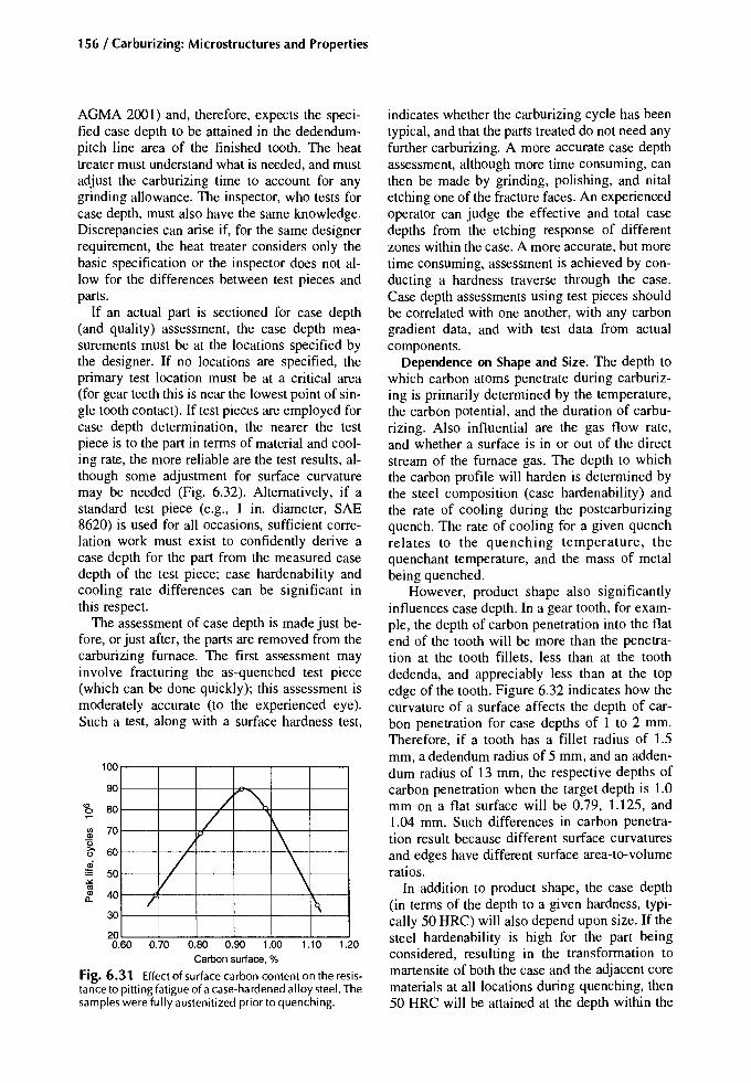
156 / Carburizing: Microstructures and Properties
indicates whether the carburizing cycle has beentypical, and that the parts treated do not need anyfurther carburizing. A more accurate case depthassessment, although more time consuming, canthen be made by grinding, polishing, and nitaletching one of the fracture faces. An experiencedoperator can judge the effective and total casedepths from the etching response of differentzones within the case. A more accurate, but moretime consuming, assessment is achieved by conducting a hardness traverse through the case.Case depth assessments using test pieces shouldbe correlated with one another, with any carbongradient data, and with test data from actualcomponents.
Dependence on Shape and Size. The depth towhich carbon atoms penetrate during carburizing is primarily determined by the temperature,the carbon potential, and the duration of carburizing. Also influential are the gas flow rate,and whether a surface is in or out of the directstream of the furnace gas. The depth to whichthe carbon profile will harden is determined bythe steel composition (case hardenability) andthe rate of cooling during the postcarburizingquench. The rate of cooling for a given quenchrelates to the quenching temperature, thequenchant temperature, and the mass of metalbeing quenched.
However, product shape also significantlyinfluences case depth. In a gear tooth, for example, the depth of carbon penetration into the flatend of the tooth will be more than the penetration at the tooth fillets, less than at the toothdedenda, and appreciably less than at the topedge of the tooth. Figure 6.32 indicates how thecurvature of a surface affects the depth of carbon penetration for case depths of I to 2 mm.Therefore, if a tooth has a fillet radius of 1.5mm, a dedendum radius of 5 mm, and an addendum radius of 13 mm, the respective depths ofcarbon penetration when the target depth is 1.0mm on a flat surface will be 0.79, 1.125, and1.04 mm. Such differences in carbon penetration result because different surface curvaturesand edges have different surface area-to-volumeratios.
In addition to product shape, the case depth(in terms of the depth to a given hardness, typically 50 HRC) will also depend upon size. If thesteel hardenability is high for the part beingconsidered, resulting in the transformation tomartensite of both the case and the adjacent corematerials at all locations during quenching, then50 HRC will be attained at the depth within the
/ -,/ r\
I \/ \
V \/ 1\
100
90
::l 70
~ 60
~ 50""os8? 40
30
200.60 0.70 0.80 0.90 1.00 1.10 1.20
Carbonsurface.%
Fig. 6.31 Effect of surface carbon content on the resistance to pitting fatigue of a case-hardened alloy steel. Thesamples were fully austenitized prior to quenching.
cg, 80
AGMA 200 I) and, therefore, expects the specified case depth to be attained in the dedendumpitch line area of the finished tooth. The heattreater must understand what is needed, and mustadjust the carburizing time to account for anygrinding allowance. The inspector, who tests forcase depth, must also have the same knowledge.Discrepancies can arise if, for the same designerrequirement, the heat treater considers only thebasic specification or the inspector does not allow for the differences between test pieces andparts.
If an actual part is sectioned for case depth(and quality) assessment, the case depth measurements must be at the locations specified bythe designer. If no locations are specified, theprimary test location must be at a critical area(for gear teeth this is near the lowest point of single tooth contact). If test pieces are employed forcase depth determination, the nearer the testpiece is to the part in terms of material and cooling rate, the more reliable are the test results, although some adjustment for surface curvaturemay be needed (Fig. 6.32). Alternatively, if astandard test piece (e.g., I in. diameter, SAE8620) is used for all occasions, sufficient correlation work must exist to confidently derive acase depth for the part from the measured casedepth of the test piece; case hardenability andcooling rate differences can be significant inthis respect.
The assessment of case depth is made just before, or just after, the parts are removed from thecarburizing furnace. The first assessment mayinvolve fracturing the as-quenched test piece(which can be done quickly); this assessment ismoderately accurate (to the experienced eye).Such a test, along with a surface hardness test,

Core Properties and Case Depth / 157
case where the carbon content is, for example,0.25%. Actually, this varies depending upon thealloy content, as Fig. 6.7 indicates. The differences in effective case depth between the toothdedendum and the tooth fillet are similar to thedifferences of carbon penetration depth as outlined above. If, on the other hand, the hardenability is not excessive or the size of the component is large so that the inner case consists ofmartensite and bainite, the carbon content neces-
sary to develop 50 HRC will be more than0.25%. How much more depends on the coolingrate that determines the proportions of martensiteand bainite. A gear tooth fillet cools more slowlyduring a quench than a gear flank does, and evenmore if the teeth are integral with a large mass,for example, as with a pinion. Therefore, at thetooth flank, the carbon content to give 50 HRC atquenching might be 0.29%, whereas at the toothfillet it might be 0.32%. On this basis alone, the
30 40 50 607080 100204 5 6 7 8 9 1032
i..,\
\
1.5 \
~ Dedendum
\ 1\ J&'\ \
J?1.0"-
1\ \r\ \
<, 1\ -,"~~
r--........,
~~--..::: -Flat surface
~-::::~
I---'~ .......
V ~~1·
1°/", .,/'V I---' I.--"
Ay/V...... ~,.
~/' ~~'
V;/ 2.0mmTPD~
/ r:i
~/ ~Fillet radius
V60
1
70
80
140
90
110
120
130
;f'.
ai~::;In
~ 100
'".2oo,f--
Radius. mm
Fig. 6.32 Effectof surface curvature on the total depth of carbon penetration (TPD). 1.0, 1.5, and 2.0 TPD refer to the total carbon penetration depth at a flat surface. The curves themselves represent departures from the flat. If a gear tooth is carburized to give a nominal total penetration depth of 1.5 mm (0.06 in.), and the tooth has a fillet radius of 2 mm and adedendum radius of 10 rnrn, then the TPD at the fillet will be -78% of 1.5 rnrn, or 1.17 mm (-0.047 in.) and the TPD atthededendum will be 109% of 1.5 rnrn. or 1.635 mm (-0.065 in.),

158 / Carburizing: Microstructures and Properties
effective case depth at the fillet could be 20%less than at the flank, and, taking into account thedifference in carbon penetration due to shape, thedifference of effective case depth (50 HRC) between fillet and flank could be around 30%. Thisaspect is important with respect to gear teeth,and it also applies to keyway comers and tochanges of diameter on shafts.
At the top and side edges of gear teeth, or theedges of keyways, there is a large area of surfacefeeding carbon into a small volume of metal; thisratio results in a buildup of carbon at the edge orcomer and carbon penetration depth appreciablygreater than at the tooth flank or in a flat surface.This can become a problem, particularly whenthe tops of gear teeth are slender, the steel is of arelatively high hardenability, and subcase cracking can ensue as a result of quenching.
Case Depth and Properties. Crude representations of how case depth and core strength can bemanipulated to counter applied bending stressesare provided in Fig. 6.33(a) to (c). These figuresindicate that there are two likely sites at whichfailure can initiate: at the surface and near thecase-core interface. Therefore, attention must bepaid to the metallurgical quality of the case andthe adjacent core at these two locations in particular. Figure 6.33, however, does not take into account the influence of residual stresses within thecase and core regions.
Residual stresses and applied stresses are additive; therefore, if the residual stresses at the surface are highly compressive (-ve), they will detract from the applied stresses (+ve) and therebyoffer some protection against crack propagationfrom the surface. If, on the other hand, the surface residual stresses are tensile due to HTIP(associated with internal oxidation, for example),then the residual stresses will augment the applied stresses and failure will be more likely toinitiate at, and propagate easily from, the surface.Metallurgical variability can be a problem, and
Shallow case
Optimum case
Potentialfailure zone
the use of shot peening more or less ensures thatthe critical surface areas are in compression andare, therefore, reinforced against failure.
Often, the compressive residual stresses peakat some distance beneath the surface (aboutmidcase), and whereas they are unlikely to influence the crack initiation process at the surface,they retard cracks propagating from the surface.
Just beyond the case-core interface, the residual stresses are tensile and balance the compressive residual stresses within the case. A survey ofdata suggested that the tensile stress peaks beneath carburized and hardened cases fell withinthe range 40 to 150 MPa (Ref 1). These tensilestresses add to the applied stresses acting just beneath the case, thereby encouraging either yielding or high-cycle fatigue damage. The deeper thecarburized case is, the further from the surfacethe potentially damaging tensile residual stresspeak is. This relationship, along with the fact thatapplied stresses diminish with distance from thesurface, reduces the chances of a fatigue failureinitiating in the core. Of course, raising the corestrength has a similar effect. However, note thatexcessive increases of case depth and/or corestrength can have an adverse influence on surface compressive-residual stresses and the residual stress distribution through the case.
Case Depth and Residual Stresses. Increasingthe case depth is more likely to favor an increased depth of internal oxidation and increasedamounts of retained austenite and free carbides,each of which can adversely affect the residualstress distribution. For example, in Fig. 6.34 retained austenite and HTTP associated with internal oxidation have each caused the surface residual stresses to be tensile. Presumably, these threetest pieces were carburized at one carbon potential; therefore, because approximately 15 h at925°C are required for the surface carbon tomore or less reach equilibrium with the carburizing atmosphere, the surface carbon contents of
Distance from surface Distancefrom surface Distance from surface
Fig. 6.33 Schematic diagrams representing the relationship between the total stress (applied and residual) and fatiguestrength of carburized and hardened steel. (a) Effect of case depth with constant core strength. (b) How case depth can bedecreased by increasing core strength. (e) Effect of stresson the location of fatigue failures

Core Properties and Case Depth / 159
360 min(1.65mm)
the test pieces differed. When the process is controlled so that, although the case thickness mightbe varied, the surface carbon content is essentially maintained, a different picture emerges(Fig. 6.35). Here, the peak compressive-residualstresses are very similar, and whereas changingthe surface carbon content influences the magnitude of the compressive stresses, it does not alterthe pattern. The lower compressive-residualstresses at the surface in those samples containing 0.9% C at the surface are attributed to thehigher retained-austenite content there.
Therefore, when carburizing to produce deepcases, this aspect of carbon potential controlshould be observed.
Residual stresses, which act as a mean stressonto which cyclic applied stresses are superimposed, are not altogether stable and can fade during aging (Ref 42) or be modified during service(Ref 40). With all case-hardened components,loading will cause a small readjustment of residual stresses, which then become, in many in-
16MnCr5, 18 mm diam 392 If.Oil quenched from 850 °C 196 ~Tempered at 180 °C Ql
~o 1jj
Iii:J
-196:><'"~
60 min20 min (0.65 mm)(0.39 mm c se depth)
0.5 1.0Distance from surface. mm
Fig. 6.34 Effect of case depth on residual stress. Influence of internal oxidation at the surface of the deep-casetest piece is also indicated. Source: Ref 40
stances, more or less stable. Therefore, in anycalculations involving residual stresses, the readjusted residual stresses will be more relevantthan the initial residual stresses. Residual stressmodification during bending-fatigue loadingtends to affect the part of the case where thehardness falls below 500 HV (see Fig. 6.36) andwhere ferrite is present in the lower case andcore (Ref 40, 43). In such cases, a significant residual stress modification will occur in the zonein which the sum of the applied stress and residual stress has exceeded the microplastic yieldstrength or the fatigue strength of the weakerstructural constituents.
For surface residual stresses to undergo change,some deformation of the austenite and martensiteis required. Such deformation could result from,for example, shot peening or deformation rolling, which increase compression. Without deformation, rolling can cause a reduction of the surface compression (Ref 44).
Bending Fatigue. Although increasing the casedepth above a certain amount improves resistance to deep contact spalling (case crushing)and pitting fatigue, it does not necessarily ensurethat the bending-fatigue resistance of the component will be improved, even if the metallurgicalquality of the case is good.
Bending-fatigue strength is influenced by section size. For example, Dawes and Cooksey(Ref 45), using Ni-Cr-Mo steels, showed thatfor 7.6 mm (0.3 in.) diameter test pieces, themaximum bending-fatigue strength was obtainedwith case depths of about 0.6 mm (0.024 in.),that is, when the case depth-to-section thicknessratio, CDlt, was approximately 0.07 to 0.08(Fig. 6.37). Aida et al. (Ref 32) obtained an optimum CDlt ratio of 0.076 working with case-
SAE 8617 I.19 mm (0.75 in.) diamOil quench I
0.75 mm Carbon potential 0.95%
(0.030 in.) "'--Case lV" /' ...depth / ...
~. ... If /. ..-,.. /\ •• ' 2.25mmIy.....; -...... .' (0.090 in')1<;»
1.4mm I(0.055 in.)
20 40 60 80 100 120
Distance from surface. mm
+140 ttla.~
<Ii0 '"eu;
Cii-140 :J
:"Q'"Ql
a:-280
3.0+2802010
Distance from surface. mm
-42020 40 60 80 100 120
SAE 8617 I..19 mm (0.75 in.) diamOil quench
0.75 mm Carbon potential 0.7%(0.030 in.) ..i--
Case IY / )./depth / ,,1'\ ..• 2.5 mm
V / ..~ (0.100 in.)
/ . .' 1.5 mm..' (O,OTJr1')1--'" ~...
.....-
o
o
3.02.01.0
-20
-40
o
-60o
'"cfi +20
g
Distance from surface. 10-3 in. Distance from surface. 10-3 in.
Fig. 6.35 Effect of case depth on residual stress. Effect of carbon potential is also indicated. Source: Ref 41

160 / Carburizing: Microstructures and Properties
800 '" 20 _ e - Fatigue tested 196EE _ Unstressed Ck15
6000,-" 0 '0!Ii »<: --- --
(') U>ci l!! /> (jj ~J:
400 iii -20 I -196!Ii
16MnCr5::> /U> "0
Ql '(;;c: l!! I Rotationalbend fatigue limit"E --40 e .-392as 200 Ck15 iii I 39 kg/mm (280 N/mm2~J: E stressedat ±38 kg/mm
Ql (±370 N/mm)2 x 106 cycleC>
0 c: --BO .-588
0 0.2 0.4 0.6 0.8 1.0 1.2~
0 0.2 0.4 0.6 0.8 1.0 1.2
Distance from surface, mm Distance from surface, mm
'" 20 196E -e- Fatigue tested as..E a._ Unstressed ~C> 16MnCr5-" !Ii!Ii 0 -- -- 0 U>
U> l!!l!! (jj(jj iiiiii -20 -196 ::>
"0::> '(;;"0'(;;
Rotational bend fatigue limit l!!l!! ~iii --40 49 kglmm (480 N/mm2~ -392
stressed at ±49 kg/mm 'EE Ql
(±480 N/mm) 12 x 106 cycles C>Ql c:C>c:
--BO -588 ~~
0 0.2 0.4 0.6 0.8 1.0 1.2
Distance from surface, mm
Fig. 6.36 Effect offatigue stressing on the tangential residual stressesin 18 mm diam case-hardened fatigue test pieces.Source: Ref 40
o 010 20 30 50 100 150
Case deoth. 10-3 in.I I I I I I I I
0.25 0.5 0.75 1.25 2.5 3.75
Case depth. mm
Fig. 6.37 Relationship between fatigue strength andcase depth for two carburized lean-alloy case-hardeningsteels. Source: Ref 45
Case depth to thickness ratio, Cd/t hardened gear teeth of 7.25 mm root thickness.Contrary to this, Tauscher (Ref 46) noted, afterreviewing several sets of published data, that theoptimum values for the CDlt ratio ranged from0.014 to 0.21. This scatter was attributed to differences in the residual stress distributions fromone set of tests to another. DePaul's results, asplotted in Fig. 6.30, suggest that alloy content orhardenability might contribute because the morealloyed a steel is, the less important the CDlt ratio is (Ref 36). Weigand and Tolasch (Ref 40)showed that component size and geometry andthe method of hardening all determined the optimum value of the CDlt ratio (Fig. 6.38a, b). Inthose tests, which involved 6 mm diameter testpieces, the CDlt ratio for maximum fatiguestrength of alloy steels was 0.07 to 0.075. Fornotched specimens (<Xk =2) the ratio was abouthalf this value. With 12 mm diameter test pieces,the relationships were more difficult to establish.Significantly, in Fig. 6.38(a) and (b) the maximum value of fatigue strength almost coincideswith the changeover from subsurface to surfaceinitiated failure. In other words, the ideal casedepth (in terms of bending fatigue) appears to bereached at the value where the failure initiation
155
930
775
0.50.20.066 0.1
En 353 and 3547.6 mm (0.3 in.) diam
Blankcarburized
10
60
50
!i 40
~Ql
g 30l!!::>"0c:W 20
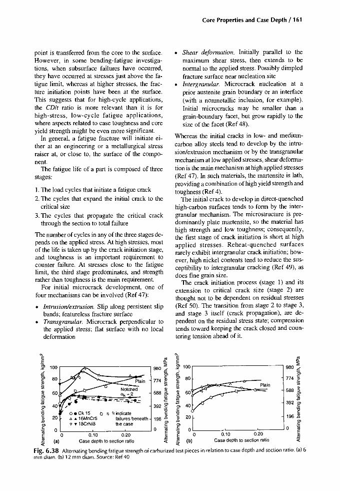
Core Properties and Case Depth / 161
point is transferred from the core to the surface.However, in some bending-fatigue investigations, when subsurface failures have occurred,they have occurred at stresses just above the fatigue limit, whereas at higher stresses, the fracture initiation points have been at the surface.This suggests that for high-cycle applications,the CDlt ratio is more relevant than it is forhigh-stress, low-cycle fatigue applications,where aspects related to case toughness and coreyield strength might be even more significant.
In general, a fatigue fracture will initiate either at an engineering or a metallurgical stressraiser at, or close to, the surface of the component.
The fatigue life of a part is composed of threestages:
1. The load cycles that initiate a fatigue crack
2. The cycles that expand the initial crack to thecritical size
3. The cycles that propagate the critical crackthrough the section to total failure
The number of cycles in any of the three stages depends on the applied stress. At high stresses, mostof the life is taken up by the crack initiation stage,and toughness is an important requirement tocounter failure. At stresses close to the fatiguelimit, the third stage predominates, and strengthrather than toughness is the main requirement.
For initial microcrack development, one offour mechanisms can be involved (Ref 47):
• Intrusion/extrusion. Slip along persistent slipbands; featureless fracture surface
• Transgranular. Microcrack perpendicular tothe applied stress; flat surface with no localdeformation
• Shear deformation. Initially parallel to themaximum shear stress, then extends to benormal to the applied stress. Possibly dimpledfracture surface near nucleation site
• Intergranular. Microcrack nucleation at aprior austenite grain boundary or an interface(with a nonmetallic inclusion, for example).Initial microcracks may be smaller than agrain-boundary facet, but grow rapidly to thesize of the facet (Ref 48).
Whereas the initial cracks in low- and mediumcarbon alloy steels tend to develop by the intrusion/extrusion mechanism or by the transgranularmechanism at low applied stresses, shear deformation is the main mechanism at high applied stresses(Ref 47). In such materials, the martensite is lath,providing a combination of high yield strength andtoughness (Ref 4).
The initial crack to develop in direct-quenchedhigh-carbon surfaces tends to form by the intergranular mechanism. The microstructure is predominantly plate martensite, so the material hashigh strength and low toughness; consequently,the first stage of crack initiation is short at highapplied stresses. Reheat-quenched surfacesrarely exhibit intergranular crack initiation; however, high nickel contents tend to reduce the susceptibility to intergranular cracking (Ref 49), asdoes fine grain size.
The crack initiation process (stage 1) and itsextension to critical crack size (stage 2) arethought not to be dependent on residual stresses(Ref 50). The transition from stage 2 to stage 3,and stage 3 itself (crack propagation), are dependent on the residual stress state; compressiontends toward keeping the crack closed and countering tension ahead of it.
Plain
0.10 0.20Case depth to section ratio
o'-- --'- ---::-':-:__~o
(b)
'" '"E 8!. E 8!.~ 100 r-----x=-------------, ~ -§, 100r--------------, ~980£ -'" 980£
~ 80 g, ~ 80 774 r~ Plain 774 ~ ~ 7i;1il Notched Q) 1il '588 ~~ 60 (Xk=2 588 5, ~ ClCl _ _~C) ~~ ._._.,.=.-_-:-_y~-= ~ 392 Cl
Cl 40 392 g> Cl C
~ 0 • Ck 15 Q >; ~ indicate 'g ~ 'gai 20 l> • 16MnCr5 failures beneath 196 ~ ai 20 196 ~~ v • 18CrNi8 thecase ~ ~ g>.~ 0 o~~ o~E 0 0.10 0.20 ~ E Q;~ (a) Case depth to section ratio <i:.S! ~<l: <i:
Fig. 6.38 Alternating bending fatigue strength of carburized test pieces in relation to case depth and section ratio. (a) 6mm diam. (b) 12 mm diam. Source: Ref 40

162 / Carburizing: Microstructures and Properties
Contact Damage. Case depth requirements forcase-hardened parts vary according to the application. For gear teeth, the case depth specification is determined by the needs of the toothdedenda/pitch-line region with respect todeep-spalling (sometimes referred to as casecrushing) resistance. Sufficient case depth fordeep-spalling resistance is regarded as morethan enough for bending-fatigue resistance.However, remember that at the gear-tooth rootfillet, the case depth is typically shallower thanat the dedendum. For bending-fatigue resistance, the quality of the immediate surface andthe residual stresses at the surface are important. In relation to wear and surface pitting,surface quality and lubrication are important.For deep-spalling resistance, the total casedepth is most influential; where the case depthis shallow or marginal, the strength of the material near the case-core interface then becomes important. Considering the large numbers or gear units that are, and have been, inservice, deep spalling remains a fairly rare occurrence (except, perhaps, in special applications such as the final reduction train of heavytractors and off-highway equipment for whichthere has been a history of such failures) (Ref51). In general, therefore, case depth specifications must have been correct, or even a littlegenerous.
Surface pitting, shallow spalling, and deepspalling are fatigue failures in which the appliedshear stresses have overcome the shear strengthof the material in the respective failure zones.There are, however, distinct differences betweenthe different types of damage, as listed in Table6.4, as there are differences in the shear stressesthat cause the damage. In Fig. 6.39, a compositeillustration compiled by Sharma et al. (Ref 53),the plots of surface shear stresses due to sliding
and contact spikes are added to the '45 and orthogonal shear stress ('yz) range curves (due torolling) to give a profile of the greatest stresstypes. Thus, any damage occurring due to theshear stresses in zone I will be shallow, for example, gear tooth pitting and surface flaking.Shallow spalling damage, which is common inbearings and bearing tracks, will occur due to the'yz shear stresses of zone II. Deep spalling failures are thought to occur due to the '45 shearstresses, which are shown here as predominant inzone III.
In their analysis of deep-spalling failures,Pederson and Rice (Ref 54) considered the '45shear stresses to be the most relevant becausethese have the greater magnitude at any depth(though not the greatest stress range). Therefore,these researchers calculated the '45 shear stressesto a depth greater than that of the case, then theytook the hardness values of the case and converted them to shear yield values. This allowedthem to compare the applied stress with the appropriate material strength property. After running tests on gears for which case depth was theprimary variable, Pederson and Rice concludedthat if the maximum shear stress-to-shear yieldstrength ratio exceeded 0.55, deep-spalling failures would eventually occur. They also believedthat the maximum bending strength was obtained by using the thinnest case in order to resistcase crushing. Because this opinion stemmedfrom their tests on gears, the case depth requiredto resist crushing would have been approximately 25 to 33% more than at the tooth fillet.It is implied that if there is enough case on thededendum to resist crushing, there should besufficient in the fillet to resist bending fatigue,provided the root fillet radius is reasonable
Table6.4 Summaryof contact failuresdescrpitiveand visual for through-hardened and surface-hardenedgearsProperty
Location of origin
AppearanceInitial sizeInitial area-depth ratioInitial shape
Crack angle with respectto surface
DistributionApparent occurrence
Source: Ref 52
Surface pitting
Surface. often at micropits
ShallowSmallSmallArrowhead then irregular
Acute
Many teethGradual
Subsurface pilting/spatting
Short distance below surface maybe at nonmetallics
ShallowSmallSmallIrregular
Roughly parallel at bottomperpendicular sides
Maybe many teethSudden
Case crushing
Probably at case-core interface
Deep ridgedLargeLargeGouged and ridged (longitudinal
gouging)Roughly parallel at bottom
perpendicular sidesOne or two teethSudden
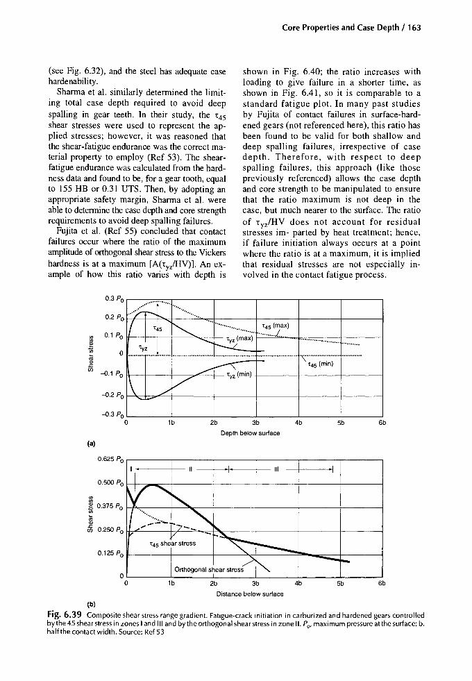
Core Properties and Case Depth / 163
(see Fig. 6.32), and the steel has adequate casehardenability.
Sharma et al. similarly determined the limiting total case depth required to avoid deepspalling in gear teeth. In their study, the t45shear stresses were used to represent the applied stresses; however, it was reasoned thatthe shear-fatigue endurance was the correct material property to employ (Ref 53). The shearfatigue endurance was calculated from the hardness data and found to be, for a gear tooth, equalto 155 HB or 0.31 UTS. Then, by adopting anappropriate safety margin, Sharma et al. wereable to determine the case depth and core strengthrequirements to avoid deep spalling failures.
Fujita et al. (Ref 55) concluded that contactfailures occur where the ratio of the maximumamplitude of orthogonal shear stress to the Vickershardness is at a maximum [A(ty/HV)]. An example of how this ratio varies with depth is
shown in Fig. 6.40; the ratio increases withloading to give failure in a shorter time, asshown in Fig. 6.41, so it is comparable to astandard fatigue plot. In many past studiesby Fujita of contact failures in surface-hardened gears (not referenced here), this ratio hasbeen found to be valid for both shallow anddeep spalling failures, irrespective of casedepth. Therefore, with respect to deepspalling failures, this approach (like thosepreviously referenced) allows the case depthand core strength to be manipulated to ensurethat the ratio maximum is not deep in thecase, but much nearer to the surface. The ratioof tyz/HV does not account for residualstresses im- parted by heat treatment; hence,if failure initiation always occurs at a pointwhere the ratio is at a maximum, it is impliedthat residual stresses are not especially involved in the contact fatigue process.
.>;:;[..... .................
I ~....
1:45 (max)1:45.........
............. ..........J.
......~:.Z....J...... ............. 1:yz (max) ...................... ..........r-..:...2:....................... ...................... ............ u •• n •••• .\.................. •• u •••••••
~~(min)1:45(min)
\ V./...........
0.3 Po
0.2 Po
'" 0.1 Po
'"eti 0~Q)L:en
-0.1 Po
-0.2 Po
-0.3 Poo 1b 2b 3b 4b 5b 6b
Depth below surface
(a)
0.625 Po .....-------r-----,------,--------r----,-----,--+~.,~--t_- III
0.500 Po I--I-:......,---t-----f------f-------t-----I------j
6b5b4b3b2b1b
OL...- --'-- --L --L ----l ~__---'
o
'"'"~ 0.375 Po I-+....-----t---""Io::__-----'I------+-----+----I------j
'"~Q)
c75 0.250 Po H7L.----+r----"'----..=1~::__--+-----+----r------i
Orthogonal shear stress
0.125 Po I------t------If----""""""-f--------=f'-_=--I------j
1:45shear stress
Distance below surface
(b)
Fig. 6.39 Composite shear stress range gradient. Fatigue-crack initiation in carburized and hardened gears controlledby the 45shear stress in zones I and III and by the orthogonal shear stress in zone II. Po, maximum pressure atthe surface; b,half the contact width. Source: Ref 53

164 / Carburizing: Microstructures and Properties
Quenching Methods
The hardening of a carburized part is achievedby cooling it at a rate that produces the desiredmetallurgical condition at, or within, the most critically loaded areas of the part. The most used techniques are direct quenching and reheat quenching.Double reheat quenching was common beforethe introduction of grain-size control, but is nowless frequently employed, though some regard itas capable of producing high-durability components. The downside is the cost of the extraquenching treatment and the risk of increased distortion with excessive corrective grinding.
When high production runs are involved, direct quenching from the carburizing temperatureor single quenching from approximately theACcm temperature are common. These methodsare suitable for those small, lean alloy steel itemsthat are not required to be die or plug quenched.
With high production runs, the chosen steelshave just enough hardenability to consistentlyproduce good quality parts; consequently, thecost per item is kept to a minimum.
Reheat quenching requires that parts be cooled,rather than quenched, after carburizing, followedby quenching at a later stage. This method is preferred for the more alloyed case-hardening gradesof steel, and with heat-treatment situations withone-off or small numbers of parts ('jobbing").There are a few reasons why this method ofquenching might be used:
• To ensure metallurgical quality, for example,grain-size and retained austenite control
0.10 r--------------,
• When an intermediate subcritical heat treatment is required, either to condition the carbides within the case or to facilitate additionalmachining
• When parts are to be plug or die quenched tocontrol distortion
• When it is not possible to direct quench (as inpack carburizing)
With low production work, matching thehardenability of the steel to the workpiece may notbe precise, and there is a tendency to err on the sideof safety by selecting steels with more than theminimum required hardenability.
Distortion
In general, case hardening significantly improves the load-carrying capacity and wear resistance of parts. Unfortunately, these benefits canbe undermined if the distortions that accompanythe carburizing and hardening processes preventthe parts from complying with design tolerances,or require an unreasonable amount of grinding torestore the size and shape to within acceptablelimits. Excessive corrective grinding could leadto unacceptable thinning of the case and, possibly, the step formation at a critical location, suchas the root fillet of a gear tooth.
There are two types of distortion: size distortion, which refers to growth or shrinkage, andshape distortion, which is essentially warpage.Growth and shrinkage relate to the volumechanges that accompany microstructural phasetransformations, while warpage relates more toasymmetrical thermal effects. If uniform growthor shrinkage were the only concerns, then, with
o~----:-'::-----~---_'o 0.5 1.0 1.5Depth belowsurface. mm
Fig. 6.40 (a) Curves showing the distribution of the'45 and 'ortho stresses during one cycle of pure rollingcontact. Note that '45 stress has the highest magnitude,but 'ortho has the greatest range. (b) Distributions of ampi itude of ratio of shear stressto Vickers hardness A(,/HV)below tooth surface at working pitch point. Derived from(a). Source: Ref 55
0.12,...----,------r---,..-----,--Carbonitrided gears
.. CNAA CNSo CNC
_ • -0- Case-hardened gears___ ••• Nitrided gears
;;-I~ ..... 0.10 f---O•......,--+-;rE~ E;: -_"0.~ .g) 0.08 I-----+---"'~...__+----t-------j
c.E.c ·x~~ 0.06 I-----+---_+-'-t,~"""d-------jOlc32g:> 0.04 L-__---l ....L -'-__---'
105 107 108 109
Numberof cycles
Fi~. 6.41 Curves of the ratio of the maximum amplitude of orthogonal shear stress to Vickers hardness[A('y)HVl]-N2. Source: Ref 55
eNS Pmax= 2000 MPa
--- A('yzlHVl
- - - A('4S/HV)
0.08
0.02
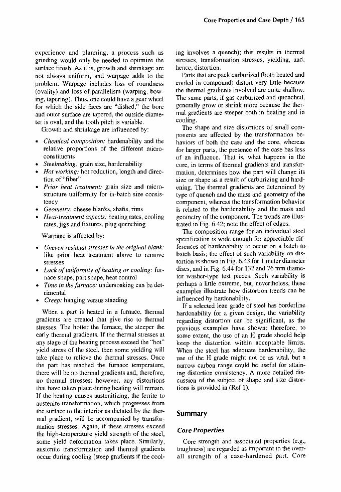
experience and planning, a process such asgrinding would only be needed to optimize thesurface finish. As it is, growth and shrinkage arenot always uniform, and warpage adds to theproblem. Warpage includes loss of roundness(ovality) and loss of parallelism (warping, bowing, tapering). Thus, one could have a gear wheelfor which the side faces are "dished," the boreand outer surface are tapered, the outside diameter is oval, and the tooth pitch is variable.
Growth and shrinkage are influenced by:
• Chemical composition: hardenability and therelative proportions of the different microconstituents
• Steelmaking: grain size, hardenability• Hot working: hot reduction, length and direc
tion of "fiber"• Prior heat treatment: grain size and micro
structure uniformity for in-batch size consistency
• Geometry: cheese blanks, shafts, rims• Heat-treatment aspects: heating rates, cooling
rates, jigs and fixtures, plug quenching
Warpage is affected by:
• Uneven residual stresses in the original blank:like prior heat treatment above to removestresses
• Lack of uniformity ofheating or cooling: furnace shape, part shape, heat control
• Time in thefumace: undersoaking can be detrimental
• Creep: hanging versus standing
When a part is heated in a furnace, thermalgradients are created that give rise to thermalstresses. The hotter the furnace, the steeper theearly thermal gradients. If the thermal stresses atany stage of the heating process exceed the "hot"yield stress of the steel, then some yielding willtake place to relieve the thermal stresses. Oncethe part has reached the furnace temperature,there will be no thermal gradients and, therefore,no thermal stresses; however, any distortionsthat have taken place during heating will remain.If the heating causes austenitizing, the ferrite toaustenite transformation, which progresses fromthe surface to the interior as dictated by the thermal gradient, will be accompanied by transformation stresses. Again, if these stresses exceedthe high-temperature yield strength of the steel,some yield deformation takes place. Similarly,austenite transformation and thermal gradientsoccur during cooling (steep gradients if the cool-
Core Properties and Case Depth / 165
ing involves a quench); this results in thermalstresses, transformation stresses, yielding, and,hence, distortion.
Parts that are pack carburized (both heated andcooled in compound) distort very little becausethe thermal gradients involved are quite shallow.The same parts, if gas carburized and quenched,generally grow or shrink more because the thermal gradients are steeper both in heating and incooling.
The shape and size distortions of small components are affected by the transformation behaviors of both the case and the core, whereasfor larger parts, the presence of the case has lessof an influence. That is, what happens in thecore, in terms of thermal gradients and transformation, determines how the part will change itssize or shape as a result of carburizing and hardening. The thermal gradients are determined bytype of quench and the mass and geometry of thecomponent, whereas the transformation behavioris related to the hardenability and the mass andgeometry of the component. The trends are illustrated in Fig. 6.42; note the effect of edges.
The composition range for an individual steelspecification is wide enough for appreciable differences of hardenability to occur on a batch tobatch basis; the effect of such variability on distortion is shown in Fig. 6.43 for I meter diameterdiscs, and in Fig. 6.44 for 132 and 76 mm diameter washer-type test pieces. Such variability isperhaps a little extreme, but, nevertheless, theseexamples illustrate how distortion trends can beinfluenced by hardenability.
If a selected lean grade of steel has borderlinehardenability for a given design, the variabilityregarding distortion can be significant, as theprevious examples have shown; therefore, tosome extent, the use of an H grade should helpkeep the distortion within acceptable limits.When the steel has adequate hardenability, theuse of the H grade might not be as vital, but anarrow carbon range could be useful for attaining distortion consistency. A more detailed discussion of the subject of shape and size distortions is provided in (Ref I).
Summary
Core Properties
Core strength and associated properties (e.g.,toughness) are regarded as important to the overall strength of a case-hardened part. Core

166 / Carburizing: Microstructures and Properties
strength is controllable within limits, for which atensile strength range (minimum to maximum)of about 155 MPa (22 ksi) is normal. Impacttoughness must be better than 27 J (20 ft lbf).
• Preprocess considerations: Steels are selectedaccording to part size and the eventual dutyrequirement. Small sections in the leanergrades of steel are best made from the Hgrades to avoid excessive variability of coreproperties.
• In-process considerations: Core properties areaffected by grain size; therefore, some thoughtis needed if high-temperature carburizing isselected. More importantly, core propertiesare affected by the makeup of the as-quenchedmicrostructure, that is, the relative proportions of martensite, bainite, and ferrite. Leansteel grades tend to produce ferritic cores, andquenching from below the AC3 temperatureresults in some undissolved core ferrite.
• Postprocess corrections: There are no corrective treatments when the core strength is outof specification following faultless quench-
ing. Tempering or refrigeration have no significant effect.
• Core properties: For heavy-duty parts, corehardness over 30 HRC is recommended because it implies an absence of ferrite in themicrostructure and provides a useful yield ratio. Hardness above 40 HRC is, in general,considered too hard. Having just enoughhardenability to provide the required strength(hardness) at the critical locations is preferable to having excessive hardenability, whichcould lead to distortion problems.
• Standards: ANSIIAGMA: for contact loading(Sac), there is no specification for grade 1, anda 21 HRC minimum for grades 2 and 3. Forbending (Sat)' grade 1 has a 21 HRC minimum; grade 2, a 25 HRC minimum; grade 3,a 30 HRC minimum. The hardness valuesquoted for both contact and bending strengthrelate to the center of the tooth at the root diameter. ISO 6336-5.2: grade ML has a 21HRC minimum; grade MQ, a 25 HRC minimum; grade ME, a 30 HRC minimum.
Carburizing steels Direct hardening steelsStainless steels
±im:W-+-
mtil:W W~ ~
~: I :: I' :, ,, ,
: i :m
42CrM04 42CrNiMo6
Dimensionalchange.mmlm
Ck45
:*.'-,: I: i :: i ::~:
~: I :: I' :, ,
: I :"Li, ,
~
~: I :, ,
: I :: j :
~-~
~ :?: I :, , ,I I :: i :l8i
~: ! :: ! :: i :~
rP-:7'r- ,
: I ,
: I :: I :
I ~ L..... :l.£+
r:~: I :: I' :, ,
: i :
~
10NiCrMo7 14NiCr14Ck15
--;:;k
:~': I, '
: I~
~:~. :: I :, ' ,: I '
~;+
l:: I :: i :'+
1-----,-----,------1-----.----,-------1 Martensitic Austenitic
X40Cr13 X5NiCrMo18
10
50-250mm
diam
50-250mm
diam
100-500mmdiam
100-500mmdiam
Oil
Water
Quenching Dimensionmedium
Fig. 6.42 Heat-treatment deformations after quenching in oil and water for different steels. Source: Ref 56
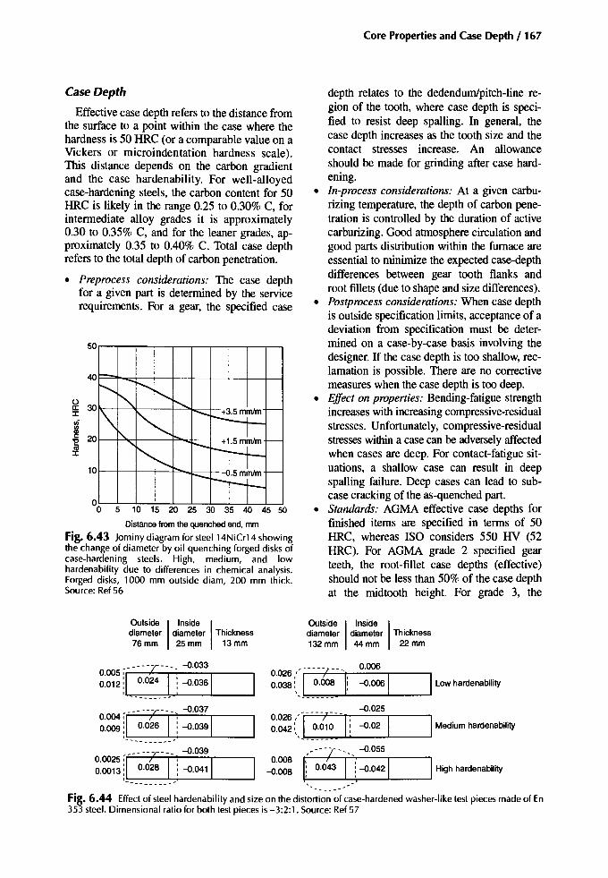
Case Depth
Effective case depth refers to the distance fromthe surface to a point within the case where thehardness is 50 HRC (or a comparable value on aVickers or microindentation hardness scale).This distance depends on the carbon gradientand the case hardenability. For well-alloyedcase-hardening steels, the carbon content for 50HRC is likely in the range 0.25 to 0.30% C, forintermediate alloy grades it is approximately0.30 to 0.35% C, and for the leaner grades, approximately 0.35 to 0.40% C. Total case depthrefers to the total depth of carbon penetration.
• Preprocess considerations: The case depthfor a given part is determined by the servicerequirements. For a gear, the specified case
101---+----+-+--f.......J::-__+_
5 10 15 20 25 30 35 40 45 50
Distance fromthequenched end.mm
Fig. 6.43 Jominy diagram for steel 14NiCr14 showingthe change of diameter by oil quenching forged disks ofcase-hardening steels. High, medium, and lowhardenability due to differences in chemical analysis.Forged disks, 1000 mm outside diam, 200 mm thick.Source: Ref 56
Outside I Inside Idiameter diameter Thickness76 mm 25 mm 13 mm
Core Properties and Case Depth / 167
depth relates to the dedendum/pitch-Iine region of the tooth, where case depth is specified to resist deep spalling. In general, thecase depth increases as the tooth size and thecontact stresses increase. An allowanceshould be made for grinding after case hardening.
• In-process considerations: At a given carburizing temperature, the depth of carbon penetration is controlled by the duration of activecarburizing. Good atmosphere circulation andgood parts distribution within the furnace areessential to minimize the expected case-depthdifferences between gear tooth flanks androot fillets (due to shape and size differences).
• Postprocess considerations: When case depthis outside specification limits, acceptance of adeviation from specification must be determined on a case-by-case basis involving thedesigner. If the case depth is too shallow, reclamation is possible. There are no correctivemeasures when the case depth is too deep.
• Effect on properties: Bending-fatigue strengthincreases with increasing compressive-residualstresses. Unfortunately, compressive-residualstresseswithin a case can be adverselyaffectedwhen cases are deep. For contact-fatigue situations, a shallow case can result in deepspalling failure. Deep cases can lead to subcase cracking of the as-quenched part.
• Standards: AGMA effective case depths forfinished items are specified in terms of 50HRC, whereas ISO considers 550 HV (52HRC). For AGMA grade 2 specified gearteeth, the root-fillet case depths (effective)should not be less than 50% of the case depthat the midtooth height. For grade 3, the
Outside I Inside Idiameter diameter Thickness132mm 44 mm 22 mm
- - - - -T - - - -0.033
0.005 ~I ; I~ 1'-----0.012i _~.~~~ i-0.036 "--__
0.004 ~I- ----7--1- ~ --{).037
1
r---
0.009L__~·026 __ .: -0.039'--__
0.0025T--- -ic rJ -0.039
10.0013i 0.028 j --{).041
---- -
0.026 " - - u - r - - _0_.006_-r- _
0.038:, I 0.008 Ii --{).006 1 ILow hardenability,-------
--{).0250.026:-1----;---1: I-I0.042:\ _nO~~~~; -0.02 Mediumhardenability
••• --;----_ --{).055 __---,
~:: t0.d43 1.( --{).042 1 IHigh hardenability
- .Fig. 6.44 Effect of steel hardenability and size on the distortion of case-hardened washer-like test pieces made of En353 steel. Dimensional ratio for both test pieces is -3:2:1. Source: Ref 57

168 / Carburizing: Microstructures and Properties
root-fillet case depth should be not less than66% of that at the midtooth height.
Case Carbon
The content target for surface carbon generallyfalls in the range between 0.75 and 0.95wt% C,where the actual target depends on the alloy content of the steel. Lean grades «2% total alloy)are carburized to carbon contents at the top ofthat range, whereas the more alloyed grades(-4% total alloy) are carburized to the lower endof the range.
• Preprocess considerations: Consider the steelgrade: for a given carbon potential, the alloycontent of the steel can influence the targetsurface carbon content. Also consider thatwith carburizing, obtaining a surface carboncontent within, for example, 0.05wt% C ofthe target value can be difficult in practice,especially when aiming for a shallow casedepth. The quenching method (direct or reheat) affects the types of surface microstructures (e.g., high austenite, grain refinement,carbides) that are produced from a given carbon content. Also consider surface carboncontent after grinding.
• In-process considerations: Ensure that the atmosphere generator catalyst is in good order;ensure good carbon potential control. Consider experience with previous work and usea test piece for carbon analysis if needed.
• Postprocess considerations: When surfacecarbon content is too high, parts can be conditioned and reheated in an atmosphere with alower carbon potential. However, this increases the case depth, possibly adding to distortion.
• Effect on properties: For a given set of process parameters, the surface carbon contentdetermines the as-quenched microstructure,which has a significant effect on properties.See Chapters 2, 3, and 4 and the section"Microcracking" in Chapter 5.
• Standards: ANSI!AGMA grades I and 2 set acarbon range of 0.6 to 1.1wt% C; grade 3 requires, 0.6 to 1.0wt% C. ISO 6336 has nolimits for its grade ML, but requires the surface carbon for the MQ and ME grades to bewithin +0.2 to 0.1wt% C of the eutectoid.
REFERENCES
1.G. Parrish and G.S. Harper, Production GasCarburising, Pergamon Press, 1985
2. Properties and Selection: Irons, Steels, andHigh-Performance Alloys, Vol 1, ASM Handbook, ASM International, 1990, p 549, 567
3.1. Woolman and R.A Mottram, Vol 2 and 3,The Mechanical and Physical Properties oftheBritish Standard En Steels, Pergamon Press,1964, p 540-559
4. J.P. Naylor, The Influence of the Lath Morphology on the Yield Stress and TransitionTemperature of Martenistic-Bainitic Steels,Metall. Trans. A, Vol 10,July 1979, P 861-873
5. How to Pick the Right Alloy to Resist Low Cycle Fatigue, Materials Engineering, July 1969
6. A Esin and W.J.D. Jones, The Effect of Strainon the AC. Resistance of a Metal: A Methodof Studying Microplasticity, 1. Appl. Phys.,Vol 18, 1967, P 1251
7. K.J. Irvine, F.E. Pickering, and J. Garstone,The Effect of Composition on the Structureand Properties of Martensite, J. Iron Steel Inst.London, U'K; Sept 1960, p 66--81
8. W.T. Chesters, "The Metallurgical Interpretation," paper presented at Why Carbon CaseHarden? (Coventry), Metals Society, 1975
9. G.V. Cleare, Int. Conf. on Gearing (London),Institution of Mechanical Engineers, 1958, p490
10.G. Feu, Bending Properties of CarburisingSteels, Adv. Mater. and Process. Inc. Met.Prog., April 1988, p 4345
II. T.B. Cameron, DE Diesburg, and C. Kim, Fatigue and Overload Fracture of a CarburisedCase, J. Met., May 1983
12. Y.E. Smith and D.E. Diesburg, Fracture Resistance in Carburising Steels, Part 1, Met. Prog.,May 1979, p 6873; Part 2, Met. Prog., June1979, p 3538; Part 3, Met. Prog., July 1979, P6771
13.V.S. Sagaradze, Effect of Carbon Content onthe Strength of Carburised Steel, Met. Sci.Heat Treat. (USSR), March 1970, p 198-200
14. R.F. Kern, Selecting Steels for Heat-TreatedParts, Part 2: Case Hardenable Grades, Met.Prog., Vol 94 (No.6), P 71-81
15.D.A Sveshnikov, LV. Kudryavtsev, N.A.Gulyaeva, and L.D. Golubovskaya, Chemicothermal Treatment of Gears, Met. Sci. HeatTreat. (USSR), July 1966, P 527-532
16.M.A Balter and LS. Dukarevich, The Relationship Between the Properties of Steels Subjected to Chemicothermal Treatment and theFatigue Limit, Met. Sci. Heat Treat (USSR),Vol 13 (No.9), P 729-732
168 / Carburizing: Microstructures and Properties
root-fillet case depth should be not less than 66% of that at the midtooth height.
Case Carbon
The content target for surface carbon generally falls in the range between 0.75 and 0.95wt% C, where the actual target depends on the alloy content of the steel. Lean grades (<2% total alloy) are carburized to carbon contents at the top of that range, whereas the more alloyed grades (-4% total alloy) are carburized to the lower end of the range.
• Preprocess considerations: Consider the steel grade: for a given carbon potential, the alloy content of the steel can influence the target surface carbon content. Also consider that with carburizing, obtaining a surface carbon content within, for example, 0.05wt% C of the target value can be difficult in practice, especially when aiming for a shallow case depth. The quenching method (direct or reheat) affects the types of surface microstructures (e.g., high austenite, grain refinement, carbides) that are produced from a given carbon content. Also consider surface carbon content after grinding.
• In-process considerations: Ensure that the atmosphere generator catalyst is in good order; ensure good carbon potential control. Consider experience with previous work and use a test piece for carbon analysis if needed.
• Postprocess considerations: When surface carbon content is too high, parts can be conditioned and reheated in an atmosphere with a lower carbon potential. However, this increases the case depth, possibly adding to distortion.
• Effect on properties: For a given set of process parameters, the surface carbon content determines the as-quenched microstructure, which has a significant effect on properties. See Chapters 2, 3, and 4 and the section "Microcracking" in Chapter 5.
• Standards: ANSI/AGMA grades 1 and 2 set a carbon range of 0.6 to 1.1 wt% C; grade 3 requires, 0.6 to 1.0wt% C. ISO 6336 has no limits for its grade ML, but requires the surface carbon for the MQ and ME grades to be within +0.2 to 0.1 wt% C of the eutectoid.
REFERENCES
1. G. Parrish and G.S. Harper, Production Gas Carburising, Pergamon Press, 1985
2. Properties and Selection: Irons, Steels, and High-Performance Alloys, Vol 1, ASM Handbook ASM International, 1990, p 549, 567
3. J. Woolman and R.A. Mottram, Vol 2 and 3, The Mechanical and Physical Properties of the British Standard En Steels, Pergamon Press, 1964, p 540-559
4. J.P. Naylor, The Influence of the Lath Morphology on the Yield Stress and Transition Temperature of Martenistic-Bainitic Steels, Metall. Trans. A, Vol 10, July 1979, p 861-873
5. How to Pick the Right Alloy to Resist Low Cycle Fatigue, Materials Engineering, July 1969
6. A. Esin and W.J.D. Jones, The Effect of Strain on the A.C. Resistance of a Metal: A Method of Studying Microplasticity, J. Appl. Phys., Vol 18, 1967, p 1251
7. K.J. Irvine, F.B. Pickering, and J. Garstone, The Effect of Composition on the Structure and Properties of Martensite, J. Iron Steel Inst. London, U.K., Sept 1960, p 66-81
8. W.T. Chesters, "The Metallurgical Interpretation," paper presented at Why Carbon Case Harden? (Coventry), Metals Society, 1975
9. G.V. Cleare, Int. Conf. on Gearing (London), Institution of Mechanical Engineers, 1958, p 490
10. G. Fett, Bending Properties of Carburising Steels, Adv. Mater, and Process. Inc. Met. Prog., April 1988, p 4345
11. T.B. Cameron, D.E. Diesburg, and C. Kim, Fatigue and Overload Fracture of a Carburised Case, J. Met., May 1983
12. Y.E. Smith and D.E. Diesburg, Fracture Resistance in Carburising Steels, Part 1, Met. Prog., May 1979, p 6873; Part 2, Met. Prog., June 1979, p 3538; Part 3, Met. Prog., July 1979, p 6771
13. V.S. Sagaradze, Effect of Carbon Content on the Strength of Carburised Steel, Met. Set Heat Treat. (USSR), March 1970, p 198-200
14. R.F. Kern, Selecting Steels for Heat-Treated Parts, Part 2: Case Hardenable Grades, Met. Prog., Vol 94 (No. 6), p 71-81
15.D.A. Sveshnikov, I.V. Kudryavtsev, N.A. Gulyaeva, and L.D. Golubovskaya, Chemico-thermal Treatment of Gears, Met. Sci. Heat Treat. (USSR), July 1966, p 527-532
16. M.A. Baiter and I.S. Dukarevich, The Relationship Between the Properties of Steels Subjected to Chemicothermal Treatment and the Fatigue Limit, Met. Sci. Heat Treat (USSR), Vol 13 (No. 9), p 729-732

17. "Bending Strength of Gear Teeth-A Comparison of Some Carburising Steels," MIRAReport 1952/5
18. H. Sigwart (quoting Ulrich and Glaubitz), Influence of Residual Stress on the FatigueLimit, Int. Can! on Fatigue ofMetals, Institution of Mechanical Engineers/American Society of Mechanical Engineers, 1956, p 272-281
19. I. Y. Arkhipov and M.S. Polotskii (quotingSemencha), Tooth Bending Life ofCase-Hardened Gears with Cores of DifferentHardness, Russian Engineering Journal, 1972,Vol LII (No. 10), P 28-30
20. W.T. Chesters, Contribution to Session IV:Materials Selection Criteria, Low Alloy Steels,lSI Publication 114, The Iron and Steel Institute, 1968, p 246-250
21. V.D. Kal'ner, V.F. Nikonov, and S.A.Yarasov, Modern Carburizing andCarbonitriding Techniques, Met. Sci. HeatTreat. (USSR), Vol 15 (No.9), p 752-755
22. R.I. Love, RC. Allsopp, and AT. Weare,"The Influence of Carburising Conditions andHeat Treatment on the Bending FatigueStrength and Impact Strength of Gears Madefrom En 352 Steel," MIRA Report No.195-9/7
23. G.V. Kozyrev, G.V. Toporov, and R.A.Kozyreva, Effect of Structurally-Free Ferritein the Core on the Impact-Fatigue Strength ofCarburized Steels, Met. Sci. Heat. Treat.(USSR), Vol 14 (No.4), p 337-339
24. RA DePaul, "Impact Fatigue Resistance ofCommonly Use Gear Steels," SAE 710277,1971
25. A. Rose and H. Hougardy, Atlas ZurWarmbehandlung Der Stahle, Vol 2, VerlagStahleisen mb, (Atlas ofthe Heat Treatment ofSteels), Dusseldorf, 1972
26. FA Stills and H.C. Child, Predicting Carburising Data, Heat Treat. Met., Vol 3, 1978, P67-72
27. K. Bungardt, E. Kunze, and H. Brandis,Betrachtungen Zur Direkthartung VonEinsatzstahlen (Consideration of the DirectHardening of Carburized Steels), DEWTechnische Berichte, Vol 5 (No.1), 1965,P 112
28. H. Schwartzbart and 1. Sheehan (Requotedfrom Ref 29), "Impact Properties of Quenchedand Tempered Alloy Steel," Final Report,ONR Contract N60NR244T.0.1, I.T.T. Chicago,Sept 1955
Core Properties and Case Depth / 169
29. G.H. Sharma, V.K. Walter and D.H. Breen,The Effect of Alloying Elements on CaseToughness of Automotive Gear Steels, HeatTreatment '87, London Institute of Metals,1987
30. C. Razim, "Survey of Basic Facts of DesigningCase-Hardened Components," unpublishedprivate print, 1980
31. B. Thodin and 1. Grosch, Crack Resistance ofCarburised Steels Under Bend Stress, Carburising: Processing and Performance Can!Proc. (Lakewood), G. Krauss, Ed., ASM International, July 1989, p 303-310
32. T. Aida, H. Fujio, M. Nishikawa, and RHigashi, Influence of Impact Load on FatigueBending Strength of Case-Hardened Gears,Bull. Jpn. Soc. Mech. Eng., Vol 15 (No. 85),1972, P 877-883
33. H. Brugger, Effect of Material and Heat Treatment on the Load Bearing Capacity of the Rootof Gear Teeth, VDI Berichte, Vol 195, 1973, p135-144
34. S.S. Ermakov and V.1.Kochev, Effect of Temperature of a Second Hardening on Resistanceto Repeated Impact of Carburised Steels,Metalloved Term. Obrab. Met., Aug 1959, p49-50
35. G.A Feu, Tempering ofCarburised Parts, Met.Prog., Sept 1982, p 53-55
36. RA DePaul, High Cycle and Impact FatigueBehaviour of Some Carburised Steels, Met.Eng. Quart., Nov 1970, p 25-29
37. D.E. Diesburg, "High Cycle and Impact Fatigue Behavior of Carburised Steels," SAETechnical Paper 780--771, 1978
38. D. Zhu, Z. Li, H. Zhai, The Application ofMathematical Statistics to the Analysis of Contact Fatigue Tests of Carburised Specimens,5th Int. Congress ofHeat Treatment of Materials (Budapest), 1986, p 1200--1204
39. B Vinokur, The Composition of the Solid Solution, Structure and Contact Fatigue of theCase Hardened Layer, Met. Trans. A, May1993, p 1163-1168
40. H. Weigand and G. Tolasch, Fatigue Behaviour of Case-Hardened Samples, Hart-Tech.Mitt., Vol 22 (No.4), P 330--338
41. W.S. Coleman and M. Simpson, ResidualStresses in Carburized Steels, Fatigue Durability of Carburized Steel, American Societyfor Metals, 1957, p 47-67
42. L. Salonen, The Residual Stresses in Carburised Layers in the Case of an Unalloyed and aMo-Cr Alloyed Case Hardened Steel After

170/ Carburizing: Microstructures and Properties
Various Heat Treatments, Acta Polytech.Scand., Series 109, 1972, P 7-26
43. Y. Udegawa, An Experimental Investigationof the Effect oflnduction Hardening of FatigueStrength: Behaviour of Residual Stress DuringApplication of Cyclic Stress, Nihon KikaiGakkai Rombunshu, 1969, Vol 35 (No. 272), p693-700
44. M. Week, A. Kruse, and A. Gohritz, "Determination ofSurface Fatigue on Gear Materials byRoller Tests," Paper 77, Del. 49, ASME, Sept1977
45. C. Dawes and R.I. Cooksey, Surface Treatment of Engineering Components, Heat Treat.Met. Special Report 95, The Iron and Steel Institute, 1966, p 77-92
46. H. Tauscher, "Relationship Between Carburised Case Depth, Stock Thickness and FatigueStrength in Carburised Steel," paper presentedat the Symposium on Fatigue Damage in Machine Parts, 1960 (Prague)
47. X. Jin and B. Lou, The Effect of the HeatTreatment and Carbon Content on FatigueCrack Initiation in Cr-Ni-Mo Steels, 5th Int.Congress on Heat Treatment ofMaterials (Budapest), 1986, p 427-434
48. M. Ericsson, Heat Treatment '87, London Institute ofMetals, 1987
49. G. Krauss, Bending Fatigue ofCarburized Steels,Fatigue and Fracture, Vol 19, ASM Handbook,ASM International, 1996, p 680-690
50. M. Hasegawa, S. Kodama, and Y. Kawada, AStudy ofthe Effect ofResidual Stress on the Fatigue Crack Propagation, 1972, p 227-235
51. M. Jacobson, Gear Design, Automot. Des.Eng., Aug 1969, Sept 1969, Oct 1969, Nov1969, Dec 1969
52. D.I. Wulpi, How Components Fail, in MetalProgress BookshelfSeries, ASM International,1966
53. G.H. Sharma, V.K. Walter, and D.H. Breen,An Analytical Approach for Establishing CaseDepth Requirements in Carburised Gears, J.Heat Treat., Vol 1 (No.1), 1980, P 48-57
54. R. Pederson and S.L. Rice, Case Crushing ofCarburized and Hardened Gears, SAE Trans.,1961, Vol 69, p 370-380
55. A. Yoshida, K. Miyanishi, Y. Ohue, K.Yamamoto, N. Satoh, and K. Fujita, Effect ofHardened Depth on Fatigue Strength ofCarbonitrided Gears, JSME Int. J. C, Vol 38(No. 1), 1995
56. P. Bloch, "Heat Treatment Distortions," Eleventh Round Table Con! On Marine Gearing,Oct 1977 (Chatham, MA)
57. DT. Llewellyn and W.T. Cook, Heat Treatment Distortion in Case Carburising Steels,Met. Techno!., May 1977, p 565-578
SELECTED REFERENCES
• M. Dubois and M. Fiset, Evaluation of CaseDepth on Steels by Barkhausen Noise Measurement, Mater. Sci. Technol., Vol 11 (No.3), 1995, P 264-267
• 1. Killey and T. GuIer, Control of the Interaction between Case Depth and Hardenabilityof Carburising Steels Using Modem Instrumentation, IMMA Conference "The Heat IsOn!" 24-25 May 1995 (Melbourne, Victoria,Australia), Institute of Metals and MaterialsAustralasia Ltd., 1995, P 35-41
• C.M. Klaren and J. Nelson, Methods of Measuring Case Depth, Heat Treating, Vol 4,ASM Handbook, ASM International, 1991, p454-461
• T. Mihara and M. Obata, Carburized CaseDepth Estimation by Rayleigh-Wave Backscattering, Mater. Eval., Vol 49 (No.6), June1991, p 696-700
• S. Singh, R. Mitra, D. Leeper, and R. Fuquen,Ultrasonic Evaluation of Case Depth inCase-Carburized Steel Components, Conf.:22nd Symposium on Quantitative Nondestructive Evaluation, Review of Progress inQuantitative Nondestructive Evaluation I5B,30 July to 4 Aug 1995 (Seattle), Plenum Publishing Corp., p 1589-1596
• B. Vandewiele, Influence of the Base Material Hardenability on Effective Case Depthand Core Hardness, Mater. Sci. Forum, Vol102-104 (No. 1), P 169-181
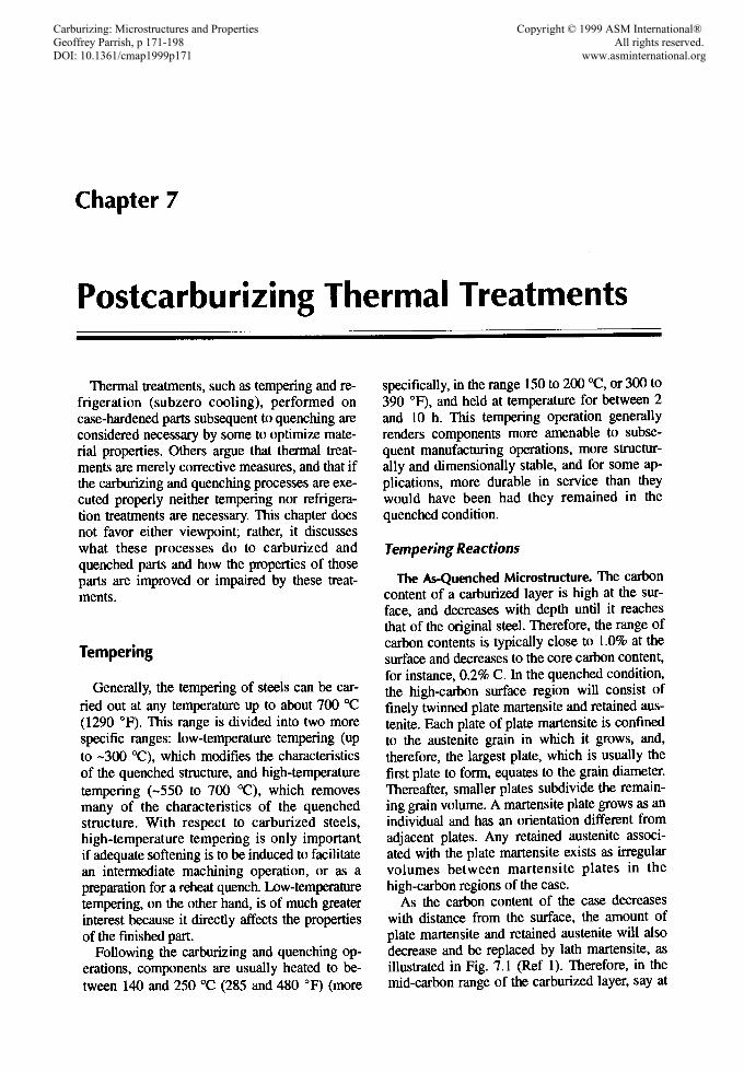
Chapter 7
Postcarburizing Thermal Treatments
Thermal treatments, such as tempering and refrigeration (subzero cooling), performed oncase-hardened parts subsequent to quenching areconsidered necessary by some to optimize material properties. Others argue that thermal treatments are merely corrective measures, and that ifthe carburizing and quenching processes are executed properly neither tempering nor refrigeration treatments are necessary. This chapter doesnot favor either viewpoint; rather, it discusseswhat these processes do to carburized andquenched parts and how the properties of thoseparts are improved or impaired by these treatments.
Tempering
Generally, the tempering of steels can be carried out at any temperature up to about 700 "C(1290 "F), This range is divided into two morespecific ranges: low-temperature tempering (upto -300 "C), which modifies the characteristicsof the quenched structure, and high-temperaturetempering (-550 to 700 0q, which removesmany of the characteristics of the quenchedstructure. With respect to carburized steels,high-temperature tempering is only importantif adequate softening is to be induced to facilitatean intermediate machining operation, or as apreparation for a reheat quench. Low-temperaturetempering, on the other hand, is of much greaterinterest because it directly affects the propertiesof the finished part.
Following the carburizing and quenching operations, components are usually heated to between 140 and 250 -c (285 and 480 oF) (more
specifically, in the range 150 to 200 "C, or 300 to390 "F), and held at temperature for between 2and 10 h. This tempering operation generallyrenders components more amenable to subsequent manufacturing operations, more structurally and dimensionally stable, and for some applications, more durable in service than theywould have been had they remained in thequenched condition.
Tempering Reactions
The As-Quenched Microstructure. The carboncontent of a carburized layer is high at the surface, and decreases with depth until it reachesthat of the original steel. Therefore, the range ofcarbon contents is typically close to 1.0% at thesurface and decreases to the core carbon content,for instance, 0.2% e. In the quenched condition,the high-carbon surface region will consist offinely twinned plate martensite and retained austenite. Each plate of plate martensite is confinedto the austenite grain in which it grows, and,therefore, the largest plate, which is usually thefirst plate to form, equates to the grain diameter.Thereafter, smaller plates subdivide the remaining grain volume. A martensite plate grows as anindividual and has an orientation different fromadjacent plates. Any retained austenite associated with the plate martensite exists as irregularvolumes between martensite plates in thehigh-carbon regions of the case.
As the carbon content of the case decreaseswith distance from the surface, the amount ofplate martensite and retained austenite will alsodecrease and be replaced by lath martensite, asillustrated in Fig. 7.1 (Ref 1). Therefore, in themid-carbon range of the carburized layer, say at
Carburizing: Microstructures and Properties Copyright © 1999 ASM International® Geoffrey Parrish, p 171-198 All rights reserved. DOI: 10.1361/cmap1999p171 www.asminternational.org
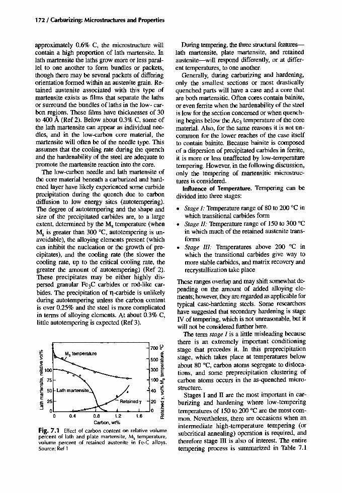
172 / Carburizing: Microstructuresand Properties
Duringtempering, the three structural features-lath martensite, plate martensite, and retainedaustenite-will respond differently, or at different temperatures, to one another.
Generally, during carburizing and hardening,only the smallest sections or most drasticallyquenched parts will have a case and a core thatare both martensitic. Often cores contain bainite,or even ferrite when the hardenability of the steelis low for the section concerned or when quenching begins below the AC3 temperature of the corematerial. Also, for the same reasons it is not uncommon for the lower reaches of the case itselfto contain bainite. Because bainite is composedof a dispersion of precipitated carbides in ferrite,it is more or less unaffected by low-temperaturetempering. However, in the followingdiscussion,only the tempering of martensitic microstructures is considered.
Influence of Temperature. Tempering can bedivided into three stages:
• Stage I: Temperaturerange of 80 to 200 °C inwhich transitional carbides form
• Stage II: Temperaturerange of 150 to 300 °Cin which much of the retained austenite transforms
• Stage III: Temperatures above 200 °C inwhich the transitional carbides give way tomore stable carbides, and matrix recoveryandrecrystallizationtake place
These rangesoverlapand may shift somewhatdepending on the amount of added alloying elements;however, theyareregardedas applicable fortypical case-hardening steels. Some researchershave suggested that secondary hardening is stageIV of tempering, which is not unreasonable, but itwill not be consideredfurtherhere.
The term stage I is a little misleading becausethere is an extremely important conditioningstage that precedes it. In this preprecipitationstage, which takes place at temperatures belowabout 80 °C, carbon atoms segregate to dislocations, and some preprecipitation clustering ofcarbon atoms occurs in the as-quenched microstructure.
Stages I and IT are the most important in carburizing and hardening where low-temperingtemperaturesof 150 to 200 °C are the most common. Nevertheless, there are occasions when anintermediate high-temperature tempering (orsubcritical annealing) operation is required, andtherefore stage ill is also of interest. The entiretempering process is summarized in Table 7.1
1.60.4 0.8 1.2Carbon,wt%
Fig. 7.1 Effect of carbon content on relative volumepercent of lath and plate martensite, Ms temperature,volume percent of retained austenite in Fe-C alloys.Source: Ref 1
approximately 0.6% C, the microstructure willcontain a high proportion of lath martensite. Inlath martensite the laths grow more or less parallel to one another to form bundles or packets,though there may be several packets of differingorientation formed within an austenite grain. Retained austenite associated with this type ofmartensite exists as films that separate the lathsor surround the bundles oflaths in the low- carbon regions. These films have thicknesses of 30to 400 A(Ref 2). Below about 0.3% C, some ofthe lath martensite can appear as individual needles, and in the low-carbon core material, themartensite will often be of the needle type. Thisassumes that the cooling rate during the quenchand the hardenability of the steel are adequate topromote the martensite reaction into the core.
The low-carbon needle and lath martensite ofthe core material beneath a carburized and hardened layer have likely experienced some carbideprecipitation during the quench due to carbondiffusion to low energy sites (autotempering).The degree of autotempering and the shape andsize of the precipitated carbides are, to a largeextent, determined by the M, temperature (whenM, is greater than 300 °C, autotempering is unavoidable), the alloying elements present (whichcan inhibit the nucleation or the growth of precipitates), and the cooling rate (the slower thecooling rate, up to the critical cooling rate, thegreater the amount of autotempering) (Ref 2).These precipitates may be either highly dispersed granular Fe3C carbides or rod-like carbides. The precipitation of n-carbide is unlikelyduring autotempering unless the carbon contentis over 0.25% and the steel is more complicatedin terms of alloying elements. At about 0.3% C,little autotempering is expected (Ref 3).
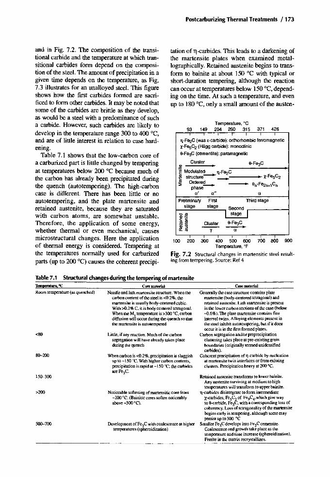
and in Fig. 7.2. The composition of the transitional carbide and the temperature at which transitional carbides form depend on the composition of the steel. The amount of precipitation in agiven time depends on the temperature, as Fig.7.3 illustrates for an unalloyed steel. This figureshows how the first carbides formed are sacrificed to form other carbides. It may be noted thatsome of the carbides are brittle as they develop,as would be a steel with a predominance of sucha carbide. However, such carbides are likely todevelop in the temperature range 300 to 400 DC,and are of little interest in relation to case hardening.
Table 7.1 shows that the low-carbon core ofa carburized part is little changed by temperingat temperatures below 200 °C because much ofthe carbon has already been precipitated duringthe quench (autotempering). The high-carboncase is different. There has been little or noautotempering, and the plate martensite andretained austenite, because they are saturatedwith carbon atoms, are somewhat unstable.Therefore, the application of some energy,whether thermal or even mechanical, causesmicrostructural changes. Here the applicationof thermal energy is considered. Tempering atthe temperatures normally used for carburizedparts (up to 200 "C) causes the coherent precipi-
Postcarburizing Thermal Treatments / 173
tation of n-carbides. This leads to a darkening ofthe martensite plates when examined metallographically. Retained austenite begins to transform to bainite at about 150°C with typical orshort-duration tempering, although the reactioncan occur at temperatures below 150°C, depending on the time. At such a temperature, and evenup to 180 DC, only a small amount of the austen-
Temperature. °C93 149 204 260 315 371 426
T1-Fe2C (was e-carolde): orthorhombic ferromagneticX-FeSC2 (Hligg carbide): monoclinic
9-Fe3C (cementite): paramagnetic
Cluster 9-Fe3C.~ •~ Modulated T1-Fe2C
X-FeSC2~ structure- _ •~ Ordere~ • 9n-Fe2n+1 Cn
phasea' a" a
Preliminary First Third stagestage stage Second
'COl I stage IQ)=:c: c:
9-Fe3C.- OlCluster~1ii --- I0:16 Y a
100 200 300 400 500 600 700 800 900Temperature, OF
Fig. 7.2 Structural changes in martensitic steel resulting from tempering. Source: Ref 4
Table 7.1 Structural changes during the tempering of martensiteTemperature. "C
Roomtemperature(asquenched)
<80
80-200
150-300
>200
500-700
Core material
Needleandlath martensitestructure.Whenthecarboncontentof the steel is<0.2%.thernanensiteis usuallybody-centeredcubic.With>0.2%C. it is bodycenteredtetragonal.WhentheMstemperatureis >300DC. carbondiffusionwilloccurduringthequenchso thatthe martensiteis autotempered
Little.if anyreaction.Muchof thecarbonsegregationwillhavealreadytakenplaceduringthequench
Whencarbonis <0.2%.precipitationis sluggishup to -150°C. Withhighercarboncontents.precipitationis rapidat -150 DC; thecarbidesare Fe3C'
Noticeablesofteningof martensiticcore from-200 DC. (Bainiticcores softennoticeablyabove-300 DC).
Development of Fe3Cwithcoalescenceat highertemperatures(spheroidization)
Case material
Generallythecase structurecontainsplatemartensite(body-centeredtetragonal)andretainedaustenite.Lath martensiteis presentin the lowercarbonsectionsof thecase (below-0.6%). The platemartensitecontainsfineinternaltwins. Alloyingelementspresentinthe steel inhibitautotempering,but if it doesoccur it is in the first formedplates.
Carbonsegregationand/orpreprecipitationclusteringtakesplaceat pre-existinggrainboundaries(originallytermedunidentifiedcarbides).
Coherentprecipitationof n-carbide by nucleationat martensitetwin interfacesor fromexistingclusters.Precipitationheavyat 200 DC.
Retainedaustenitetransformsto lowerbainite.Anyaustenitesurvivingat mediumto hightemperatureswill transformto upperbainite.
n-carbides disintegrateto form intermediateX-carbides, FeSC2of Fe9C4'whichgivewayto 9-carbide,Fe3C,witha correspondinglossofcoherency. Lossof tetragonalityof the rnanensitebeginsearly in tempering.althoughsomemaypersistup to 300 °C
SmallerFe3CdevelopsintoFe3Ccementite.Coalescenceand growthtakeplaceas thetemperatureand time increase(spheroidization).Ferritein the matrixrecrystallizes.

174 / Carburizing: Microstructures and Properties
Tempering temperature, °C
Fig. 7.3 Variations in theamounts of carbide phases withtempering temperature. Temperingtime,S h. Source:Ref5
c: 0.006 0.~
iii 0.005 5c:0
~ 10OS!-
E 0.004~0 15
'lii 0.003c:
c: Ol
~ 20 iii:::l
00.002 <
'1::25a;
E:::l 0.001 30(5>
s: 5ojE..
8C>3 ec:
":iiQ.E{£ 1
150 200 450
Tempering temperature. °cFig. 7.4 Precipitation of E-, X-, and 9- (Fe3C) carbidesrelated to tempering time and temperature. (1.34% Csteel). Source: Ref 10
o ~
10-2 10- 1 1 10 1'02 103 1()5
1 day 1 yearTime,h
Fig. 7.5 Thermal-induced volumetric transformationstrain for carburized 4320 steel (35% retained austenite)as a function of temperature and time. Source: Ref 11
trated in Fig. 7.4, and an example of the time dependence of retained austenite transformation isshown in Fig. 7.5. These figures show that for agiven amount of reaction, temperature and timecan be traded against one another. Aston, working with medium-carbon through-hardeningsteels, favored using higher tempering temperatures for shorter durations (Ref 12). Unfortunately, this is not typically a good idea forcase-hardened parts in view of the need to expelhydrogen absorbed during the carburizing operation. Also note that carbon migration can continue at room temperature following the tempering operation (Ref 13, 14). This is aging. Agingis mentioned later in connection with hydrogeneffusion. Consider also the effect of temperingtime on the state of the martensite matrix, that is,the loss of tetragonality that takes place at temperatures below 300 °C.
Volume Changes during Tempering. Inquenched steels, the austenite-to-martensite transformation is accompanied by an increase of volume; the higher the carbon content is, the greaterthe volume increase. Thus, the high-carbonmartensite in the surface of a carburized layer will
Toll l't,..
~IP-J ./~caii\ lJ' I
Ir:-- Fe3c
~ 1.2% C...
I II 'f
~6 ... \ jjrbide
I 'rfI ~V~ /. x-carbideI~'...I"~ N..../ .;J ""'-
18
16
OS!- 14oj
'"01s: 12Q.
Ol
~ 10~'0 8C:::l0E 6-c
12
10OS!-ai'"01 8s:Q.
Ol:2e 6~'0C 4:::l0E-c
2
0 '"0 100 200 300 400 500 600 700
Tempering temperature, °C
4
2
oo 100 200 300 400 500 600 700 800
ite is affected. As a rule, most of the austenite retained during quenching survives a typicallow-temperature tempering, and though austenitetransformation proceeds more easily and morerapidly above about 180°C, some austenitemight survive to quite high temperingtemperatures. Austenite transformation duringlow-temperature tempering produces lowerbainite, whereas medium- and high-temperaturetempering will cause an austenite to upperbainite reaction.
Over the years there have been numerous studies of the tempering process; of these, Ref 5 to 9have been used for this review, though not as anyspecific statement.
Influence of Time. The time dependence ofcarbide precipitation during tempering is illus-
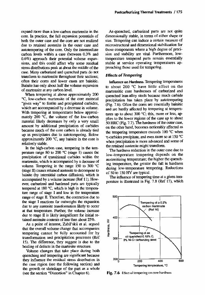
PostcarburizingThermal Treatments / 175
400I------+-~,---f_---__i
600
Tempering of a 0.2%carbon martensite
(Ref 16)
200 400
Tempering temperature, °C
Tempering of anoil-quenched 0.18% C,
3% Ni-Cr carburizing steel
200L-----l-------:-":-:-----:=o
300
Fig. 7.6 Effect of tempering on core hardness
5OO...------,-----r------,
As-quenched, carburized parts are not quitedimensionally stable, in terms of either shape orsize. Tempering can induce a certain measure ofmicrostructural and dimensional stabilization forthose components where a high degree of precision and stability are vital. Furthermore, lowtemperature tempered parts remain essentiallystable at service operating temperatures approaching those used for tempering.
Effects of Tempering
Influence on Hardness. Temperingtemperaturesto about 200°C have little effect on themartensitic core hardnesses of carburized andquenched lean-alloy steels because much carbideprecipitation has taken place by autotempering(Fig. 7.6). Often the cores are essentially bainiticand are hardly affected by tempering at temperatures up to about 300 DC; this, more or less, applies to the lower regions of the case up to about50 HRC (Fig.7.7). Thehardnessofthe outer case,on the other hand, becomes noticeablyaffectedasthe tempering temperature exceeds 100°C whenn-carbidesprecipitate, and even more so at 150 "Cwhen precipitation is more advanced and some ofthe retainedaustenitemight transform.
The hardnessreduction in the outer case due tolow-temperature tempering depends on theaustenitizingtemperature; the higher the quenching temperature, the greater the fall in hardnessduring low-temperature tempering. Reductionsof 50 to 150 HV are typical.
The influenceof temperingtime at a giventemperature is illustrated in Fig. 7.8 (Ref 17), which
expand more than a low-carbon martensite in thecore. In practice, the full expansion potentials ofboth the outer case and the core are not realizeddue to retained austenite in the outer case andautotempering of the core. Only the intermediatecarbon levels within a case (between 0.3% and0.6%) approach their potential volume expansions, and this could affect why some residualstressdistributions peak at about the middleof thecase. Many carburizedand quenchedparts do nottransformto martensite throughouttheir sections;often their cores and lower cases are bainitic.Bainite has only about half the volume expansionof martensiteat any carbon level.
When tempering at above approximately 200DC, low-carbon martensite of the core material"gives way" to ferrite and precipitated carbides,which are accompanied by a decrease in volume.With tempering at temperatures below approximately 200 DC, the volume of the low-carbonmaterial likely decreases by only a very smallamount by additional precipitation of carbidesbecause much of the core carbon is already tiedup as precipitates due to autotempering. Belowapproximately 200 DC, any bainite in the core isrelatively stable.
In the high-carbon case, tempering in the temperature range 80 to 200 "C (stage 1) causes theprecipitation of transitional carbides within themartensite, which is accompanied by a decrease ofvolume. Tempering in the range 150 to 300 "C(stageIl) causesretainedaustenite to decompose tobainite (by interstitial carbon diffusion), which isaccompanied by a volumeincrease (Ref 11).However, carburized and hardened parts are typicallytempered at 180°C, which is high in the temperature range of stage I and low in the temperaturerange of stage IT. Therefore, the contraction due tothe stage I reactions far outweighs the expansiondue to any austenite transformation likely to occurat that temperature. Further, the volume increasedue to stage IT is likely insignificant for initial retainedaustenite contents of less than about25%.
As a point of interest, Zabil'skii et al. arguedthat the overall volume change that accompaniestempering cannot be fully accounted for bytransformation and precipitation processes (Ref15). The difference, they suggest is due to thehealing of defects in the rnartesite structure.
Volume changes that take place during bothquenching and tempering are significantbecausethey influence the residual stress distribution inthe case region (see the following section) andthe growth or shrinkage of the part as a whole(see the section "Distortion" in Chapter 6).

176 / Carburizing: Microstructures and Properties
from tempering at about 100 "C, with the yieldstrength approaching the ultimate tensilestrength. At higher tempering temperatures, the
200
1000
200
800
~
1000
800
~'i
6008.
400 j
50 100 150 200 250 300Tempering temperature, °C
50 100 150 200 250 300Tempering temperature, °C
-
-O8OM15
(approximately SAE1016)
MS~
0.2%'PS -"1----'"-:-0 LP_. . --. _.... - -l>- ~_06 I
Corehardness
j 6651M17 J -
(appr ximately SAE4615)MS.0.2% PS
...... --- ~IO.l%PS~
./v~pl
Corehardness
oo
oo
200
200
u;Ul
~ 150
8~a.0_ Ul
~Gl=~ 100lllUl
§E~.§e-~
0.18 liE 50%C '0
0.14 'E::::i
Distance fromsurface, mm123
go 600F~~~r-f"'~r-r--r--t__j
'ii 500F:;F~;::::::-i~ct--'~:-T-_t_-i
"E:'i! 400F=1=~-.J--~....;~~~,-t-~
7001-------11-----"I....,...-+--+--+--I---+-----1
2000 0.02 0.04 0.06 0.08 0.10 0.12Distance fromsurface, in.
Fig. 7.7 Effect of tempering on case hardness of a3%Ni-Cr carburizing steel with 0.18% C
shows that above approximately 120 minutes, little further change of hardness is likely to occur.
Influence on Tensile Properties. Just as thehardness of the core material is essentially unchanged by tempering at temperatures up to 250to 300 "C, so too the tensile strength remains unchanged. The local yield strength for lean-alloyand alloy carburizing steels tends to rise duringtempering at temperatures between 100 andapproximately 250 "C, whereas plain-carboncarburizing steel are hardly, if at all, affected(Fig. 7.9).
Within the quenched carburized case, an increase of both tensile and yield strengths results
200
1000MSI~ -
0.2%PS
---- ~l0/JpS-
l---"" .,..-r-
~
LPn
/ :r-
.. ...... L • -l>_. .06
Corehardness -
835M17 ..I(nominally 4% Ni, -
1.3%Cr, 0.25%Mo)
200
oo 50 100 150 200 250 300
Tempering temperature, °C
Fig. 7.9 Effectoftempering ~n the core tensile prope~ties of three steels.Blank carburized core steel: 920 °C 011quench, reheated 780-830 DC, oil quenched, cooled to-78 DC, and tempered. LP, limit of proportionality; PS,proof stress;MS, maximum stress. Source: Ref 18
~1ii 150O·en0'><a.u;
_ Ul
~gIII Ul 100§ El§2 ~c. E 50'0
'E::::i
eloo °C o 200°C
<, _120°C 'l'220°C -o150°C ""240°C
<, ,,180°C v 260°C -
---.r---<;<,--.:::....---~ -----
--r'--
68
67
66
650II:
64:I:
lZGl 63c"EIII:I: 62
61
60
5930 60 90 120 150 180
Tempering time,minutes
Fig. 7.8 Hardness of carburized and hardened steel30KhGT as a function of tempering temperature andtime. Source: Ref 17

Postcarburizing Thermal Treatments / 177
2400
2000
1600
~ 8;:;;<Ii 12001Il #. 6l!!Cii C
0
800 :s 4Cll:.2 2w
00 250
pering, then straightening without cracking canbe difficult to achieve. This aspect of temperinghas been examined by Vogel, who obtainedfewer reject shafts by straightening in the untempered condition (Ref 21).
Residual Stresses. Compressive-residualstresses within the carburized layer contributegreatly to the useful properties of case-hardenedparts. As-quenched, the residual stress distribution through a carburized case varies largely according to the relative proportions of retainedaustenite and martensite (discounting surfaceanomalies). The magnitude of compressive- residual stresses at or near the surface (where theaustenite may be present in significant quantities) is generally less than at some distance below the surface, at locations where the microstructure is wholly martensitic and the carboncontent is approximately 0.5 to 0.6%.
Tempering reduces the magnitudes of both thecompressive stresses within the case and the balancing tensile stresses within the adjacent core(Fig. 7.11). Moreover, tempering tends to shiftthe location of the peak compression nearer tothe case-core interface. Several factors contributeto the as-quenched residual stress distributionwithin a case and core, and these influence howmuch the stress magnitudes fall due to temperingat some appropriate temperature. Figure 7.12shows examples of peak stress reduction due totempering.
A comparison of Table 7.1 and Fig. 7.12 reveals that carbide segregation and precipitationclustering coincide with the initial minor decrease of compressive residual stresses, and that
Extension
68
66
64 oII:J:<Ii
62 1IlGll:"Eos
60 J:
58
56250 300
(8)
(b)
Fig. 7.10 Effectof tempering temperature on the tensile yield strength of two steels. (a) Composite stressstrain curve for a Ni-Cr steel (0.57% C, 3.07% Ni, 0.9%Cr) where arrows denote limit of proportionality.Source: Ref 19. (b) Stress for 0.001 plastic deformation(aO.OOl) for a high-chromium bearing steel (ShKh15)after quenching and cold treatment (soak time 3 h).Source: Ref20. 1 kglmm 2 = 9.8 MPa
1oo=------:~---...l.:----..J150 200
Temperature,OC
220,.------~----r-----
Steel ShKh 15
fall in hardness that accompanies tempering isreflected by a fall in tensile strength. However,the yield strength of the high-carbon case, inkeeping with that of the core material, tends torise as the tempering temperature rises to 250°C(Fig. 7.lOa, b). This particular feature can causeproblems during any post-case-hardeningshaft-straightening operation. Straightening tocorrect heat-treatment distortion requires that theshaft beplastically strained in a direction that opposes the heat-treatment distortion. If the yieldstress is closer to the fracture stress due to tem-

178 / Carburizing: Microstructures and Properties
0.2 0.4 0.6 0.2 0.4 0.6 0.2 0.4 0.6 0.2 0.4 0.6Distance from surface. mm
Fig. 7.11 Residual stresses (tangential) in cyanide-hardened 40Kh rings before and after tempering (for 1.5 h). Ring dimensions: 80 mm outside diam x 66 mm inside diam x 15 mm high. Casedepth 0.22 mm (on outside diam only). Source:Ref22
'"E If
t.'""I~ '1"'~
!:~f~}~j:tx .... __ 0
o 40 --- } 392 ...... NOTCHEO iiiiii "Jed :t::~ 20 9918CrNi8 196 ~= .1>.16 MnCrS Q)Q) O. Ck 15 6,
.j 00 200 400 600 0 ~u; Tempering temperature, °C
Fig. 7.13 Effect of tempering temperature on the alternating bending fatigue strength of 6 mm diam casehardened test pieces. Carburized at 930°C for 1 h, waterquenched, reheated to 850°C for 10 minutes, and oilquenched. Note: Ck15 steel was water quenched from850°C. Source: Ref 25
these carbides. The change of slope that takesplace above approximately 160 "C is the sum ofthe contractions due to precipitation and the expansions accompanying the onset of retainedaustenite transformation (Fig. 7.12). However,when the n-carbide disintegrates to form othertransitional carbides or Fe3e above about 200"C, a volume contraction occurs, and the peakcompressive stresses again fall and continue tofall as carbide coalescence advances, as cohesionbetween carbide and matrix is lost, and as theferrite matrix attempts to recrystallize with risingtemperature, up to approximately 700 "C.
Influence on Bending Fatigue. Tempering temperatures below 100 "C do not greatly influencethe bending-fatigue strength of small case- hardened gears. With higher temperature treatments(to 200 0C), the fatigue limit progressively reduces by up to approximately 20% (Table 7.2).A similar trend was found when small beamsamples were fatigue tested (Table 7.3). At tempering temperatures between 200 and approximately 250 "C (the range in which retained austenite transforms to bainite), the fatigue limit
300 0O'---~--~--~---L-J
(b)
...go -a82ox 40Kh
'E -ao • SAE8620 -784
~ '" 16MnCrS.... -70
0 SCr22-a86 os
01 a,01 ::iE~ -ao -588 <Ii
01iii !I!:§ -50 -490 ~01 os!I! ::>
"C
! -40 -392 .~c:Q)
-294 §g' -30S E
E.~
g -20 -196 ::iE
'1;1...g8::iE -10
0 0
(a)0 100 200 300
Tempering temperature, °C
-soSteel SCr22
-a82
'E-aD Casedepths from0.2to 0.8mm-784
~... -70 -a86 If<Ii01 ::iEt-60 -588 l2iii !I!-6-50 -490 ~"iii os!I! ::>
"Ciii -40 -392 .~~Q) Eg'-3Q -294 ::>
S E
§ -20"~
E-196 ::iE
'1;1::iE -10 ...g8
o 100 200Tempering temperature, ·C
Fig. 7.12 Change in peak compression due to tempering after carburizing and (a) oil quenching or (b) waterquenching. Source: Ref 22-25
precipitation of n-carbides and loss of martensitetetragonality coincide with the major reductionof surface compressive residual stresses. A decrease of volume accompanies the formation of

Postcarburizing Thermal Treatments / 179
Table 7.2 Theeffect oftempering onthefatigue andimpact resistance ofEn352 packcarburized at 900°Candquenched from 870°C
Bar Impact
FetigueUmIt 'Ibotb Impact Uoearburized Carburlzed
Temperature, "C MPa k.si J ft·lbf J ft ·lbf J ft ·lbf
Untempered
NA 800 116 32.5 24 12 9 21.5 16NA 910 132 35 26 13.5 10 8 6NA 910 132 36.5 27 12 9 6.5 5NA 880 128 23 17 9.5 7 4.5 3.5NA 880 128 34 25 11.5 8.5 12 9NA 827 120 36.5 27 11 8 4.5 3.5
tempered
100 854 124 36.5 27 13.5 10 4 3100 840 122 31 23 15 11 4.5 3.5150 780 113 47 35 17.5 13 4.5 3.5150 705 102 27 20 15 11 7.5 5.5200 760 110 40.5 30 16 12 6.5 5200 637 92 28.5 21 17.5 13 4 3
NA is notapplicable.Source:Ref26
may increase a little before decreasing again atstill higher tempering temperatures when most ofthe retained austenite has transformed (Fig.7.13).
Gu et al., showed that under low-cycle fatigueconditions, the fatigue-crack initiation life increases as the residual compression within thecase increases (Fig. 7.14) (Ref 27). Tempering,however, reduces compression (Fig. 7.11) (Ref22), and consequently one might expect it to reduce the number of stress cycles for crack initiation. Fett stated that tempering at 180°C increased the low-cycle fatigue life (withoutaffecting the high-cycle fatigue life) (Ref 28).Therefore, one conclusion that can be derivedfrom these observations is that for low-cycle fatigue, at least, tempering must induce some significant resistance to crack propagation.
The retained austenite content appears to affect how a steel responds to tempering. For example, Razim examined the extremes of austenite content and found, using notched rotating
Effect of tempering onfatigue
Residual stress, MPa
I
-500 -600
A Carbonitrided
16CrNi4Mo
A Carburized
o Carbonitrided
20CrNi2Mo
• Carburized
I
--400
3 I I
-100 -200 -300
5
beam test pieces, that tempering at 180°C reduced the fatigue limit of a fully martensitic«2% retained austenite) case structure by onlyapproximately 3%, but that it also appeared toreduce the low-cycle fatigue strength considerably (Ref 29). When the case contained largequantities of retained austenite (-80%), tempering at 180°C caused an 18% increase in fatiguelimit, and pushed the knee of the S-N curve to alonger time (Fig. 7.15). Note, however, that thetest pieces with the high austenite content were
30
x:ll 20
~
860
866858847823767
±525±495
±570
±570±51O
Fatigue 1boitMPalsi
±35±33
±38±34
±38As carburizedandquenched
Temperedat 60°CTemperdat 100°CTemperedat 125°CTemperedat 150°CTemperedat 185°C
Condition
Table 7.3
Testpieces2.38mmthick x 12.7mmwide in SAE8620H.Casedepth0.37~.45 mm. Source:Ref 24
Fig. 7.14 Variation of fatigue-crack initiation lives withresidual stress at the notch of tested steels. Source: Ref 27

180 / Carburizing: Microstructuresand Properties
Table 7.4 Influences on the toughness ofcase-hardened structures
Property Lowering hydrogen content Tempering Storage after tempering 81200 "C for 2 h
CracktoughnessFracturetoughnessTimeto delayed failurePulsatingfatiguetoughnessFatiguestrengthunder
reversedstress
NoeffectPositiveeffectPositiveeffect
NoeffectNoeffect
PositiveeffectPositiveeffectPositiveeffectPositiveeffectNegativeeffect
PositiveeffectPositiveeffectPositiveeffectPositiveeffect
Noeffect
Source: Ref 13
720r-----r------y-------,
300
lXi<=2
200100
-=:: 0 0.----.o 18CrNi8. reheat quench (850°C)• CK 15. water quench (850°C)
6mmdiam
~.-------.-
Temperingtemperature. °C
Fig. 7.16 Effectoftempering on the alternating bendingfatigue strength of two case-hardened steels. Source: Ref25
ing. Because many actual components havestress concentrators, for example, gear tooth fillets, the notched test-piece results perhaps indicates the right trend. Streng et al. determined thattempering has a favorable effect on pulsating fatigue toughness and a deleterious effect on thefatigue strength under reversed stress (Table 7.4)(Ref 13).
Most laboratory fatigue tests are operated under constant load conditions and, as such, do nottake into account the likelihood of occasionalhigh-loading events. Real-life components canexperience occasional overloads in addition totheir normal operating load, whether that ishigh-cycle low load, low-cycle high load, orsomewhere in between. Considering the advantages and disadvantages of tempering, designersand operators require guidance about whether ornot to temper. Rosenblatt attempts to providesuch guidance with respect to gears in Fig. 7.17(Ref 30). His work implies that tempering is essential for the high-load low-cycle requirement
'0; 1000:¥.
s£c, 8!. 900c:
~::i:il
Gl '":::J .!!! 800OJ o
i ~<0
OJ~c: 700'6
c: 0Gl ~
alOJs: 600C,c:~
5000;Gl::l
f 400
3000
.. 0...
.e, ~.. 0. .. .. . 0. ..b..
.. 0.. 0 80. 't1.
....'.0
-,
Martensite:• Not tempered
6901---- • Tempered 180°Cfor2h - 100Austenite:
........ 0 Nottempered6601---................:>0",.-- °Tempered 180·C for2 h ---A-
"~ .....:;~-, :=8!.
::i:~ 600I------'~o-----t_--=-........
~CIl 5701-------',;--t----=-oL;>--ot_---"'----l:::JOJ
Sg> 5401------.r----.p..~--_l'6c:~
14NICr14(3.76% Ni-O.78%Cr)
420L-------'------'----...J1~ 1~ 1~ 1@
Load cycles
Fig. 7.15 Bending-fatigue strength of notched testpieces with and without retained austenite. Source: Ref29
450)--------'-------"'t-i:J------l
always inferior to those essentially free of austenite. Most case-hardened components have retained austenite contents of 10 to 30%.
It is apparent that many variables (e.g., steelcomposition, microstructure, test-piece design,and type of loading) have a bearing on the fatigue strength and how it is affected by tempering. Figure 7.16 shows how tempering to 180 °Creduces the unnotched bending-fatigue strengthof a case-hardened alloy steel, yet raises thesame property of a carburized plain-carbon steel.In the notched and carburized condition, the fatigue limits of both the alloy steel and theplain-carbon counterpart are reduced by temper-

and where impact loading is involved. For thelow-load high-cycle situation, tempering mighthave an adverse effect. However, other considerations, such as dimensional stability andgrindability, might determine whether or not apart should be tempered.
Influence 00 Cootact Fatigue. Under pure rollingcontact fatigue conditions, that is, those comparable to the contact at the pitch line of a geartooth, it was found that the fatigue limit of reheat-quenched and tempered test rollers increases as the tempering temperature increases,up to 250°C. However, in a low-cycle high-loadregime, the contact-fatigue life diminishes as thetempering temperature increases (Fig. 7.18). Itwas noted that the highly loaded test tracks of theuntempereddisks increased in hardness by up to85 HV and those of the disks tempered at 100°C increased by up to 120 HV, whereas thosetempered at 150°C or more hardened by only 35HV. This effect is considered to be related to theincrease of yield strength due to tempering (Fig.7.10).
It should be remembered that tempering temperatures above about 150°C (300 OF) maytransform some of the austenite to bainite; thehigher the temperature is, the greater the amountof austenite transformed. According to the standard ANSIIAGMA 2OO1-C95, bainite has a detrimental effect on the resistance to both contactand bending fatigue.
Influence on Bending and Impact-FractureStrength. A study to determine the impact-fracturestress of case-hardened steels with differingchemical compositions revealed that the im-
Postcarburizing Thermal Treatments / 181
pact-fracture stress increased as the maximumcompressive-residual stress of the case increased (Fig. 7.19) (Ref 31). All samples hadbeen tempered at 170°C. Therefore, it might bereasoned that if tempering reduces the compressiveresidual stresses, then the absence of temperingshould lead to higher fracture stress. This doesnot seem to be so. Shea observed that temperingat 165 °C increases the energy required to initiatea crack in a conventionally carburized andquenched test piece under impact loading, butit had little, if any, influence on the crackpropagation energy (Ref 32). Because the
t
250°C200
!-----+------t---'l.-----1OO
20
106
Cyclesto failure
Fij:t. 7.18 Influence of tempering temperature on therolling-contact fatigue limit of a carburized and hardenedalloy steel.
Residual stress, ksi
-40 -50 --eO -70 -eo -90. ..High stress
/'0 ~ 3500Impaet(A) .. 500
Low eyelet- (8) g1;b! ::!:III .;
~c (I)
r/.'" ~ ~ .;~ c 0 l!!
(e) High cycle-+0 ~ 3000o 0
Root bending 100 h - :l.. U ~resistancevs.tempering"tt ii g .561 400j(A) Temperingrequired
'" U(B) Temperingbeneficial '0 os 0561(e) Temperinghas varyingelled 10 h Co
~...§ 2500(0) Temperingmay be deleteriousVuy high eyele-+ (D) :s Co
Low stress • EX32 .§0 SAE 4820
102 103 1()4 105 10· .107 10·300Required life in cycles
-300 -400 -500 --eOOFig. 7.17 Effect of low-temperature tempering on theservice Iife of carburized and hardened gears. Root bending resistance vs. tempering: (A) impact, tempering required; (B) low cycle, tempering beneficial; (C) highcycle, tempering has varying effect; (0) very high cycle,tempering may be deleterious. Source: Ref 30
Maximum compressive residual stress, MPa
Fig. 7.19 Relationship between impact-fracture stressand compressive-residual stress(percent values indicatemaximum amount of retained austenite content in thecarburized case). Source: Ref 31

182 / Carburizing:Microstructures and Properties
Impact resistance is increased by the correcttempering temperature and time, as Fig. 7.20 illustrates. In this example, a tempering temperature of 180 to 200 QC for a minimum of 90 minproduced the best results. Using steels of varyingnickel content (::;;4.6%), Thoden and Groschshowed that the bending-crack stress and the impact strength were each improved by temperingat 180 QC for 1 h, as was the case for both directquenched and double-quenched samples (Ref33). Another study using unnotched test pieces(Table 7.5), indicated that impact toughness of8620 steel was little affected by tempering in thewider range applicable for case-hardened parts(150 to 250 QC). However, the bending strengthwas improved (Fig. 7.21) (Ref 34). Subsequentgear-set life tests with impact loading showedthat tempering had been beneficial.
In fracture-toughness tests on a 0.85% Clean-alloy steel, as-tempered samples exhibitedfractures with larger areas of transgranular fracture surface than did the fractures of untemperedsamples (Ref 35), implying that tempering canbenefit fracture toughness. Other factors, such asaustenitizing temperature, cooling rate, and phosphorus content, were found to affect the appearance of the fracture and the KIc value. A slowquench rate and a high phosphorus content together contributed to grain-boundary carbonenrichment or iron-carbide precipitation, causingmore intergranularfracturesurface and a lowerKIc-
1501209060
30 KhGTsteelCase depth, 1.1-1.2 mm
If-------j----=:;;;;o4l- eloo °C 0200 °C
.120°C v220°Col50°C t.24O°C~180°C .260°C
1.5.'::------='::------='::__--~:__---,..J30
'Es"'"~s:Cl:::>oS 2.5 ....=---t----+---~"'----____1
I
Temperingtime, minutes
Fig. 7.20 Effect of tempering temperature and time onimpact toughness of unnotched test pieces. Note: untempered impact toughness -2 kglcm2• Source: Ref 17
crack-initiation energy increased, and thecrack-propagation energy was essentially unaffected as a result of tempering, which had probably reduced the surface compression, one canreason that residual stresses have no effect whenthe loading is by impact.
Table 7.5 Dataon as-quenched and temperedunnotchedCharpybarsfollowing gascarburizing
1empering Charpy Slowbend test resultsSample AISI temperature, Hardn.... HRC Case depth, mm (in.) Impact energy, Yield, Ultimate, Deflection,No. erode °C (oF! Surface Core Effective Visual J(ft·lbf) kNQb) kNQb) mm(in.)
1 8615 As-quenched 66 36 0.89 (0.0035) 1.02 (0.040) 16-20 (12-15) 19.6(4400) 30.2 (6780) 0.086(0.034)2 8615 150(300) 634 37 0.97 (0.038) 1.02 (0.040) 24-26 (18-19) 27.6(6200) 33.2 (7460) 1.02 (0.040)3 8615 205 (400) 59-<i1 35-36 0.91 (0.036) 1.02 (0.040) 26-30 (19-22) 27.6 (6210) 35.1 (7900) 1.07 (0.042)4 8615 260(500) 58-59 35-36 0.91 (0.036) 1.02 (0.040) 19-31 (14-23) 34.3 (7700) 39.2 (8820) 1.42 (0.056)5 8615 315 (600) 55-56 36 0.084 (0.033) 1.02 (0.040) 43-56 (32-41) 32.0(7200) 42.9(9640) 1.45 (0.057)6 8615 370(700) 51-53 34 0.58 (0.023) 1.02 (0.040) 53-144 (39-106) 28.0(6300) 42.2 (9480) 2.39 (0.094)7 8615 425 (800) 48-49 32 0.036 (0.013) 1.02(0.040) 175-231 (129-170)8 8615 480(900) 45-46 29-30 1.02 (0.040) 264-302 (195-223) 23.6 (5300) 35.1 (7900) 5.08 (0.200)9 8620 As-quenched 64-66 45 1.17 (0.046) 1.14 (0.045) 24-30 (18-22) 22.2(5000) 34.6(7780) 1.09 (0.043)10 8620 150(300) 62-65 45-46 0.91 (0.036) 1.14 (0.045) 34-39 (25-29) 32.9(7400) 37.4(8400) 1.09 (0.043)11 8620 205 (400) 59-60 45-46 1.09 (0.043) 1.14 (0.045) 33-60 (24-44) 29.8(6700) 38.7 (8700) 1.12 (0.044)12 4320 As-quenched 64 46 1.40 (0.055) 1.52 (0.060) 26-28 (19-21) 26.7(6000) 34.3(7700) 1.17 (0.046)13 4320 150(300) 61-63 46 2.65 (0.065 ) 1.52 (0.060) 38-41 (28-30) 27.1 (6100) 36.9(8290) 1.14 (0.045)14 4320 205 (400) 58-59 46-47 1.40 (0.055) 1.52 (0.060) 43-47 (32-35) 30.2(6800) 38.4(8640) 1.17 (0.046)15 8617 150(300) 60-61 38 0.99 (0.039) 0.91 (0.036) 22-45 (16-33) 28.9(6500) 36.1 (8100) 1.12 (0.044)16 4815 150(300) 58 42-43 1.22 (0.048) 0.91 (0.036) 53-79 (39-58)17 4820 150(300) 58 40-41 0.89 (0.035) 0.86 (0.034) 58-68 (43-50) 28.0(6300) 37.0(8320) 1.40 (0.055)
Bars 1-14 carburized in one group. Bars 15-17 carburized in one group. All bars cold-oil quenched. Spectrographic analysis of Charpybarsbyweight percent: 8615M: 0.18 C. O.64Mn. 0.36Ni. 0.48 Cr. 0.12 Mo; 8620: 0.19 C. 0.74Mn. 0.59 Ni, 0.43 Cr. 0.17 Mo; 4320: 0.21 C, 0.49Mn, 1.89Ni. 0.38 Cr. 0.28Mo; 8617: 0.20 C. 0.91 Mn. 0.45 Ni. 0.51 Cr. 0.17Mo; 4815: 0.16C. 0.57Mn, 3.42Ni. 0.24Mo: 4820: 0.18 C. 0.75Mn. 3.13Ni.0.24Mo

Postcarburizing Thermal Treatments / 183
Tempering temperature, °C
53842731620493701,8__---, T"-__-.-__--.-__---,
200 10,000 0.200(271) (44) (5.1)
8,000
o 150 (36) 0.150II: (203) ~ (3.8):I: Eur 3- ,e .§..,Q) B 6,000
~c .5'E . (27)-= c Cas l!! 0.100:I: 100 l 1ii i(136) Cl) (2.5).E c
4,000 '5c c(18) Q)
m
50 0.050(68) 2,000 (1.3)
(9)
°20 0 0 0
0 200 400 600 BOO 1000
Tempering temperature, of
Fig. 7.21 Mechanical properties of unnotched AISI 8615 Charpy bars at various tempering temperatures. Bars weregas carburized to 1.02 mm (0.040 in.) visual depth, cold oil quenched to 50 "C. Source: Ref 34
o 0.58%C• 0.81%C• 0.92% C+ 1.00%C61.23%C
200 300 400 500 600100
400 LL..__....L...__L-_...L-_.l...--'-_'__--'
20
1400
t')
~ 1200
E~1000oc
*'iii 800l!!Qj~ 600
Temperingtemperature, °C
Fig. 7.22 Effect of tempering temperature on wear resistance. Source: Ref 36
as well as aspects of design, should be examinedas much, if not more than, the metallurgical quality of the wearing surfaces.
Additional Process Factors
Hydrogen Content. The outcome of bendingand impact tests on case-hardened steels can becomplicated by the presence of hydrogen in thesteel. Hydrogenation results directly fromhigh-temperature heating in an atmosphere containing molecular hydrogen and a hydrogen
Influence on Wear. The abrasive wear resistance of high-carbon surfaces is related to hardness and the distribution of dispersed carbides(Ref 36). As the tempering temperature increases, the wear resistance decreases (Fig.7.22). The main fall in resistance results fromtempering in the temperature range 125 to 225 "C(-400 to 500 K), the temperature range generallyused for carburized and hardened parts. Theshape of the plots in Fig. 7.22 appears to relate tothe changes that take place during tempering,that is, the carbon clustering, carbide precipitation, concurrent austenite transformation, andmatrix change from martensite (a.') to ferrite (n),
Figure 7.22 applies to dry abrasive wear and,to some extent, is applicable to adhesive wear.However, adhesive wear is influenced by thechemistry of the mating surfaces, where, for example, nickel tends to favor adhesion, and, incase-hardened surfaces, retained austenite mightalso favor adhesive wear (e.g., scoring and seizure).
Machines with parts that move relative to oneanother generally require a lubricant of adequateviscosity and flash temperature to inhibit or control both abrasive and adhesive wear of either ofthe contacting surfaces. Therefore, in the eventof excessive wear, the condition of the lubricantand the effectiveness of the lubricating system,

184 / Carburizing: Microstructuresand Properties
Table 7.6 Tensile propertiesof20Crand 18CrNiW steels
Steel
20Cr
18CrNiW
Heat treatment
As-quenchedQuenchhardening plus190DC x 2h temperingAs-quenchedQuenchhardeningplus 190DC x 2 h tempering
Vacuum hardeningStrength, MPa Reduction of area, %
1520 381500 381471 561422 61
Blank carburized and quenchedStrength, MPa Reduction of area, %
1442 101471 151412 131392 43
Source:Ref37
Table 7.7 Theeffectof hydrogen on the toughness ofthe core material of0.2%C,3.5Ni-Cr carburizingsteelTreatment Reduction of area, % Crack initiation, kg(· cm Deflection,mm Bending load, kgf
HeatedinairHeatedinendo-gas
58(53)27(58)
78(80)10(58)
0.8 (1.1)0.1 (0.8)
840(850)640(840)
Numbers in parenthesesshowthe testvaluesafter 14daysaging.The originalvalueswereobtainedsoonafter heat treating.The bendingloadandthe deflectionwerethoseat the timeof crackinitiation. Source:Ref39
Hydrogencontent,ppm
Fig. 7.23 Influence of hydrogen content on the crackstressand fracture stress. Source: Ref 38
60
....................""o
10
.................., ...0'·
0,'- Crackv, 0
o .~.-.----_.- •• -.---------.
23oo°r---...,::.---=;::--.::;..--;::---=r:....-~2200 20MoCr4.ChargeA
67HRC2100 Notlempered
Ol 2000
~ 1900o 1800en!!! 1700en
1600
1500 °1400 ~ •• -o·_·_···_· .• _~.._.....•..... __ ._.
o °1300 L::--...I...----I..::----::l-----"l..:-::---:cl:-::-~~1.75 0.9 0.6 0.4 0.35 0.30 0.25
ther, it was observed that tempering, according toits duration, raises the crack-initiation stress; atleast four hours at the tempering temperature isnecessary to reach the maximum stress value.Adequate tempering is considered effective forreducing the hydrogen content and removingthe adverse effects of hydrogen; vacuum tempering is more effective than air tempering.
Aging. Two aspects of the aging of carburizedand hardened steels must be considered: its effect, if any,on any residual hydrogen in the steel,and the possible additional migration of carbonatoms.
Carburized bend or toughness test piecesheated in endo-gas will have relatively lowtoughness and ductility following a quench. During testing to fracture, the initial crack is morelikely to be influenced by the surface carboncontent than the hydrogen present. Crack propa-
Thmpering Tempering Approximate Approximatetemperature, time, maximum maximum·C h load,kllf deflection, mm
150 0 880 0.025 1210 0.1
10 1380 0.22180 5 1500 0.4
10 1580 0.48
Source:Ref 39
Table 7.8 Effect oftemperingon the bendtestresults ofa 3.5%Ni-Cr steelheated inendothermicgasandquenched
compound, that is, water vapor in an endothermic gas.
The hydrogen content of steel surfaces aftergas carburizing and hardening has been measured as approximately 2 ppm (Ref 37, 38).Subsequent tensile tests on as-quenched samples and on quenched and tempered samples(190 °C for 2 h) showed that tempering raisesthe percent reduction of area value (Table 7.6)and is also beneficial regarding delayed fractureunder load (Ref 37). The influence of temperingon the time to delayed failure was confirmedwhere tempering time was considered more influential than tempering temperature (Ref 38).Dukarevich and Balter observed that hydrogenhas an adverse influence on toughness and ductility (Table 7.7) and that tempering improvesbending strength depending on tempering timeand temperature (Table 7.8) (Ref 39). Streng etal. established that the amount of stress requiredto induce a crack is not affected by the hydrogencontent, whereas the stress required for crackpropagation is affected to a degree dependent onthe hydrogen content (Fig. 7.23) (Ref 38). Fur-

Postcarburizing Thermal Treatments /185
Table 7.9 Carboncontentofmartensite and the changes of residual stressduringa test periodof16months fora 20MoCr4 steel
QuenchingconditionsCarbon, %
Start EndCompressive resldual.tre.s, MPaStart End
ouaso-cOil at 50 ·c plus -196 ·C subzero coolOilat200·COil at 1O·C plus 175·C temper
0.57 0.490.62 0.460.24 0.210.40 0.40
510 440550 500450 420250 250
Carburize 900 ·C for I h 20 minutes for effective case depth (0.4 C) of 0.35 mm and a surface carbon content of 0.8--0.85%.0.25 mm layerremoved to reach zone of maximum residual stress. Peak residual stress coincides with the point where the carbon content equals 0.60%.Source: Ref 14
gation, on the other hand, is affected by thetoughness of the core material, which is influenced by the hydrogen content. Aging permitsoutgassing of hydrogen with a corresponding improvement of toughness and ductility (Table7.7).
Tests carried out after a 16 month roomtemperature hold revealed that in as-carburizedand quenched parts, the carbon content of themartensite and the compressive-residual stressesfell (Table 7.9) (Ref 14). Samples tempered at175 "C exhibited no carbon change in themartensite or in residual stress values. Therefore, tempering is important both for hydrogeneffusion and for carbon stabilization within thecarburized and hardened case.
The fatigue strength of case-hardened andtempered (220°C) pieces tested under reversedloading was unaffected by subsequent storage,whereas the pulsating-fatigue strength increased
during holding for approximately 100 days (Fig.7.24).
Grinding.Ground surfaces are the product ofgouging, rubbing, and rolling by hard abrasiveparticles bonded into the surface of the grinding wheel. A ground surface is plastically deformed and heat affected, and as a result, itssurface properties are modified. Even in aburn-free ground surface, the local yieldstrength and the residual stresses are alteredwith grinding.
Tempering, typically at 180 "C, reduces thetetragonality of the martensite and induces precipitation of transitional carbides within themartensitic structure of the entire case. Thus, thesurface is made more structurally uniform, tosome extent, and is preconditioned against surface temperatures of up to 180 "C that might begenerated during grinding or in service. An un-
93
101
I2OMoCr4E, Charge B, tempered 220 ·C for 2hRatio of minimum stress to maximum stress, 0.8
0
• 0 096
0100 104 100
0 99 97<10100
..;;
2 ••• .6• 3 28 • 7cfe83 • 6
,2 3 <1
2I- • Storage time 2--8 days, fractures in the notch
• Storage time 93-104 days, fractures in the notch
n Storage time 93-104 days, fractures in the hole, diam 7.8 mm
<1 Specimen without rupture
1000
3000
2500
Number of cycles
Fig. 7.24 Influence of the storage time at room temperature on the pulsating-fatigue strength. Source: Ref 38

186 / Carburizing: Microstructuresand Properties
tempered part, on the other hand, is sensitive toany temperaturerise above ambient.
Tempering after grinding should be considered. It could reduce favorable surface compressive stresses generated during grinding;likewise, it could take the peak off tensilestresses similarly developed. Further, temperingis believed to raise the yield strength of theground surface material and, consequently,would be expected to improve the resistance ofthe surface to fatigue-crack initiation (Table7.10) (Ref 20).
Refrigeration
It is not uncommon for a refrigeration (subzerotemperature) treatment to be included in the carboozing and hardeningprogram, either as a standard procedure or as an optional operation. Ittransforms to martensite excess austenite retained after the hardening quench, thereby (a) increasing the surface hardness, (b) reducing thepropensity to produce burns and cracks duringsurface grinding, and (c) at least partially ensuring the dimensional stability of critical precisionparts.
The latter quality (c) is not usually regarded asimportant for general engineering applications,and refrigeration is used without concern aboutits effect on dimensions. However, there are special applications for which dimensional stabilityis vital, and refrigeration is therefore justified.Where grinding is involved (b), even moderateamounts of retained austenite can be tolerated,especially if the austenite is fine and well distributed and good grinding techniques are employed. It is primarily the surface hardness requirement (a) that dictates the need to treat atsubzero temperatures. Whatever the reason is forrefrigeration, it is prudent to low-temperaturetemper after the treatment.
Influence on Hardness. The specified minimum surface hardness of case-hardened components does not normally fall below 650 HV (58HRC). However, with alloy grades of carburizingsteel, particularlythose containingover 2% Ni, itcan be difficult to realize the specifiedminimumsurface hardness when the surface carbon content is high. In such cases, the retained austenitecontent at or near the surface exceeds 30% (assuming that softening has not resulted fromdecarburization, high-temperature transformation products associated with internal oxidation,
or poor quenching); therefore, a refrigerationtreatment is likely necessary.
Cesaroneexamined the effects of both tempering and refrigeration on the retained austeniteand hardness of carburized and hardened SAE9310 steel samples (Ref 40). In the as-quenchedconditions (of which there were twelve) the retained austenite contents varied between 30 and80%. Refrigeration of the as-quenched samplesreduced the retained austenite by amounts related to the original retained austenite contentand the refrigeration temperature (Fig. 7.25a).Whereas tempering the as-quenched material ledto only a 10% reduction of retained austenite,tempering after refrigeration was far more effective for reducing the austenite, particularly foraustenitecontents over approximately50%. Thissuggests that refrigeration had destabilized theremaining austenite. The as-quenched hardnessfell in the 55 to 65 HRC range. Refrigerationnarrowed that range to 62 to 66 HRC (averaging63.9 HRC) (Fig. 7.25b), and subsequent tempering modified it to 60.5 to 65 HRC (averaging62.5 HRC) (Fig. 7.25c). Subzero treating at-196°C in liquefied natural gas (LNG) reducedthe retained austenite of the as-quenched material by about lO%yR more than did freezing at-80°C, and it raised the hardness by approximately 1 HRC.
Whether or not an "in-line" refrigerationtreatment should be employed for all processedcomponents is somewhat debatable becauseso much depends on the steel grade and theprocessing in general. It is prudent to considerthe effects of the process variables and usethem to control austenite retention before resorting to refrigeration as a programmedtreatment. The process variables that might bemanipulated are: quenching temperature (Table 7.11), surface carbon content (Table 7.12),the chemical composition of the steel (Table7.13), and the use of reheat quenching (Table7.14). Based on the work of Koistinen andMarburger, the quenchant temperature should
Table 7.10 Microyield stress(0"0.00') ofgroundsurfacesProcess aOMJ,MPa
Quench.subzerotreat. ISO·C temperfor 3 h. grind 114Quench,subzerotreat, ISO·C temper for 3 h, 133
grind, 140 ·C temper for 3 hQuench,subzerotreat, ISO·C temper for 3 h. 153
grind. 140 ·Ctemperfor24h
Source: Ref20

(b)
Retained Estimatedaustenite, hardne...
Steel M.. 'C Ms-Tg,oC % HRC
0.8%-4.5%Ni-I.4%Cr 50 30 60 480.8%-2.0%Ni-0.3%Cr 110 90 35 56
Surface Heat Retained Surfacecarbon,% treatment austenite,% hardness, HRC
0.9 Oilquenchedfrom820'C. 32 54Temperedat 150 'C
0.8 Oilquenchedfrom820'C. 28 56Temperedat 150 DC
0.7 Oil quenchedfrom820DC. 20 58Temperedat 150 'C
Quenching Tempering Surrface Probabletemperature temperature, hardness, austenitecontent,
Steel (intooill,"C "C HRC %
18Kh2N4VA 850 140 54 >3018Kh2N4VA 800 140 59 -20
Steels quenched from 850 'c. Tq• quenchant temperature. taken to be20 DC
Table 7.13 Effectof alloy content on retainedaustenite
Table 7,12 Effectof surface carbon content onretained austenite (estimated for a 3.5%Ni steel)
Source: Ref41
Postcarburizing Thermal Treatments /187
Table 7.11 Effectof quenching temperature onretained austenite
theoretically also have an influence on thequantity of austenite retained (Table 7.15)(Ref 42); experimental work using quenchanttemperatures of 60 to 140°C essentiallyagreed (Ref 44). Shea, on the other hand, determined that there was no significant variation of retained austenite when quenchant temperatures were 50 to 270°C for a carburizedSAE 4130 steel or when quenchant temperatureswere 50 to 235°C for an SAE 1526 steel (Ref32).
The effectiveness of subzero treating at either-120 or -196°C is indicated in Table 7.14 whereappreciable quantities of retained austenite aretransformed, and significant hardness increasesare achieved. These macrohardness values represent the hardnesses of aggregates of martensiteand austenite (and carbides, if present). What theydo not show is that the austenite surviving refrigeration is strengthened. Microhardness tests on retained austenite in a 1.2 to 1.3% C surface, performed before and after refrigeration at -120°C,indicated an increase of hardness from 520 to650 HV (Ref 39).
10 20 30 40 50 60 70 80
Retained austenite aftertreatment, %
//
V/
As quenched/
/ Quenched,
/ sUbzerotreated,I
/andtempered
at 150 'C
I I
Quen6hed andsubzJro ~enched Q~enchedtreated andtempered _ andsubzero andtempered _
at 150 "C treated at 150 "C
+,
/ '/,), ., ..
/:' / .·V./
. / .V, .. / As quenched,,, / .. / ./,, ,,
1 r .Y/
/' carburizedand
1/ hardjned 9r0 -
Q'uenChed/ '/
andtempered / /at 150'C
/ /// /
/ / As quenched
/ Quenchedandsubzero -
traited
68
54
56
54
~
56
66
64
66
52~ ~ 56 56 60 ~ ~ 68 68
Finalhardness. HRC
80
90
68
10
oo
(8)
(/!.
~ 70c;
S 60~~ 50
~ 40
2g 30
sf( 20~
~J: 62
tnc;i60
~.s::.1ii 56
~
o~ 62
~l!! 60"E21ii 58
~
52~ ~ 56 56 60 ~ ~ 68 68
Finalhardness, HRC(c)
Fig. 7.25 Changes of retained austenite content andhardness due to refrigeration (-196 and -80 DC) and tempering (150 DC). (a)Effectof refrigerationand tempering onretainedaustenite content. (b) Individual effects of tempering and refrigeration on surfacehardness. (c) Effect of refrigeration andtemperingon surface hardness. Source: Ref40

188 / Carburizing: Microstructures and Properties
Table 7.14 Effectof subzero cooling after quenchingHeattreatment Retained austenite, Hardness, Bending strength Impactafter<arhurl.lng Condition % HRC MPa kg/mmI MPa ke/mJl11Oil quenchedfrom 800 ·C. As-quenched 62 54 1530 156 25.5 2.6
low-temperaturetempered Subzero treated 20 62 1442 147 19.5 2.0Temperedat 650 ·C. oil As-quenched 34 60 1697 173 40 4.1
quenchedfrom 800 ·C. Subzerotreated 10 62 1608 164low-temperaturetempered
Air cooled from900-7SO·C. As-quenched 90 47 1618 165 59 6.0oil quenched. Subzerotreated 20 60 1353 138 19.5 2.0low-temperaturetempered
SteeI18Kh2N4VA.Subzerotreatmentscarriedout at-120 ·C. For fatiguedata. see Fig. 7.27. Source:Ref 43
Influence on Tensile Properties. The ultimatetensile strength of a steel in the quenched condition is little affected by refrigeration, even to-196°C. The yield strength, on the other hand,rises as the refrigeration temperature decreases,so much that the yield strength (0.2% proofstress) of a high-carbon steel can be marginallylower than the ultimate tensile strength (Table7.16) (Ref 45). This increase of yield strength islikely a consequence of reduced austenite particle size brought about by the subdivision of austenite volumes by the martensite produced during refrigeration. The ductility indicators,
Table 7.15 Effectof quenchant temperature onretained austenite
Approximate E.timatedretained hardness,
Ms,"C Tq, "C Ms-Tq,"C austenite(a), % HRC
ISO 80 70 45 52ISO 60 90 35 56150 40 110 29 57150 20 130 25 58
<a) Ms. martensitestart temperature;Tq•quenchant temperature.Thisrefers to the austenitecontent of Tq. Withfurthercooling.more transformationwill takeplace. buta significantamountof stabilizationwillhave occurred. Source:Ref 42
elongation and area reduction, decrease as thetemperature of the refrigeration treatment decreases.
Influence on Fatigue Resistance. The currentopinion is that moderate to high quantities of retained austenite are beneficial to the low-cyclefatigue resistance of carburized and hardenedparts, and are detrimental to the high-cycle fatigue resistance (Ref 46). Refrigeration to reducethe austenite content, therefore, is expected toadversely affect the low-cycle fatigue strengthand favor the high-cycle fatigue strength. This,however, is not the case: refrigeration has oftenbeen found to have an adverse effect on bothhigh- and low-cycle fatigue resistance.
Roberts and Mattson showed that a subzerotreatment at -75°C reduces the low-cycle bending fatigue strength of case-hardened SAE 8620test pieces (Fig. 7.26) (Ref 47). Using notchedtest pieces, Sveshnikov et al. found that thehigh-cycle fatigue limit of a 20KhNM steel isimproved by refrigeration at -75°C, whereas thesame treatment on the leaner Kh40 steel reducesthe fatigue limit (Table 7.17) (Ref 22). In anotherstudy, refrigeration at -120°C marginally increased the torsional fatigue strength of acase-hardened 3.5%NiCr steel (Fig. 7.27, curves
Table7.16 Effectof subzero treating on mechanical propertiesTreatment Ultimatetensile Yield Retained
temperature, strength, strength, Elongation, Fatigue, Kk' austenite,Materiai(a) ·C MPa kg/mmZ RA,% % kg/mmZ kgJmm3/Z % (/';a)/a x 10-3(h)
50KhtemperinglSO·C 235 190 16.5 6.6 % 82 6.1 4.45-50 237 194 14.5 6.1 102 88 5.9 2.3-90 238 196 13.5 4.3 1M 90 5.4 2.57
-1% 237 207 10.0 3.2 97 83 2.2 2.98SOKhNtempering lSO·C 230 188 10.5 7.2 92 76 5.7 4.08
-70 238 200 13.0 5.7 99 83-1% 239 206 12.0 4.2 90 73
ShKh15tempering 200 ·C 241 198 3.08 88 65 15.8 4.24-50 243 206 2.97 100 75 14.9 3.44-90 246 224 1.7 96 70 10.5 3.93
-1% 239 229 1.04 90 66 8.2 4.01
<a)Through-hardenedmaterials.Nominalcompositionsare SOKh: 0.5% C. 0.6%Mn, 1.0%Cr.<0.3%Ni. <0.3%Cu; 50KhNi:0.5% C. 0.6%Mn,0.6% Cr, 1.2%Ni. <0.3%Cr; ShKhI5: 1.0%C. 1.5%Cr. <0.3%Ni, <0.25%Cu. <b) Distortionsincrystal lattice in IX solid solution
188 / Carburizing: Microstructures and Properties
Table 7.14 Effect of subzero cooling after quenching Heat treatment after carfaurizing
Oil quenched from 800 °C, low-temperature tempered
Tempered at 650 °C, oil quenched from 800 °C, low-temperature tempered
Air cooled from 900-750 °C, oil quenched, low-temperature tempered
Condition
As-quenched Subzero treated As-quenched
Subzero treated
As-quenched Subzero treated
Retained austenite,
Steel 18Kh2N4VA. Subzero treatments carried out at -120
% 62 20 34 10
90 20
Hardness, Bending strength HRC MPa kg/mm? 54 1530 156 62 1442 147 60 1697 173 62 1608 164
47 1618 165 60 1353 138
°C. For fatigue data, see Fig. 7.27. Source: Ref 43
MPa 25.5 19.5 40
59 19.5
Impact kg/mm2
2.6 2.0 4.1
6.0 2.0
Influence on Tensile Properties. The ultimate tensile strength of a steel in the quenched condition is little affected by refrigeration, even to -196 °C. The yield strength, on the other hand, rises as the refrigeration temperature decreases, so much that the yield strength (0.2% proof stress) of a high-carbon steel can be marginally lower than the ultimate tensile strength (Table 7.16) (Ref 45). This increase of yield strength is likely a consequence of reduced austenite particle size brought about by the subdivision of austenite volumes by the martensite produced during refrigeration. The ductility indicators,
Table 7.15 Effect of quenchant temperature on retained austenite
M^-C
150 150 150 150
rq,°c 80 60 40 20
M,-TV°C
70 90
110 130
Approximate retained
austenite(a), %
45 35 29 25
Estimated hardness,
HRC
52 56 57 58
(a) Ms, martensite start temperature; 7q, quenchant temperature. This refers to the austenite content of 7q. With further cooling, more transformation will take place, but a significant amount of stabilization will have occurred. Source: Ref 42
elongation and area reduction, decrease as the temperature of the refrigeration treatment decreases.
Influence on Fatigue Resistance. The current opinion is that moderate to high quantities of retained austenite are beneficial to the low-cycle fatigue resistance of carburized and hardened parts, and are detrimental to the high-cycle fatigue resistance (Ref 46). Refrigeration to reduce the austenite content, therefore, is expected to adversely affect the low-cycle fatigue strength and favor the high-cycle fatigue strength. This, however, is not the case: refrigeration has often been found to have an adverse effect on both high- and low-cycle fatigue resistance.
Roberts and Mattson showed that a subzero treatment at -75 °C reduces the low-cycle bending fatigue strength of case-hardened SAE 8620 test pieces (Fig. 7.26) (Ref 47). Using notched test pieces, Sveshnikov et al. found that the high-cycle fatigue limit of a 20KhNM steel is improved by refrigeration at -75 °C, whereas the same treatment on the leaner Kh40 steel reduces the fatigue limit (Table 7.17) (Ref 22). In another study, refrigeration at -120 °C marginally increased the torsional fatigue strength of a case-hardened 3.5%NiCr steel (Fig. 7.27, curves
Table 7.16 Effect of subzero treating on mechanical properties
Materiai(a)
Treatment Ultimate tensile Yield temperature, strength, strength,
• C M P a kg/mm2 RA, %
Retained Elongation, Fatigue, Klc, austenite,
% kg/mm2 kg/mm 3P % (Aa)/a x 10-3(b)
50Kh tempering 150 °C
50KhNtemperingl50°C
ShKhl 5 tempering 200 °C
-50 -90
- 1 %
-70 -196
-50 -90
-196
235 237 238 237 230 238 239 241 243 246 239
190 194 196 207 188 200 206 198 206 224 229
16.5 14.5 13.5 10.0 10.5 13.0 12.0
6.6 6.1 4.3 3.2 7.2 5.7 4.2 3.08 2.97 1.7 1.04
96 102 104 97 92 99 90 88 100 96 90
82 88 90 83 76 83 73 65 75 70 66
6.1 5.9 5.4 2.2 5.7
15.8 14.9 10.5 8.2
4.45 2.3 2.57 2.98 4.08
4.24 3.44 3.93 4.01
(a) Through-hardened materials. Nominal compositions are 50Kh: 0.5% C, 0.6% Mn, 1.0% Cr, <0.3% Ni, <0.3% Cu; 50KhNi: 0.5% C, 0.6% Mn, 0.6% Cr, 1.2% Ni, <0.3% Cr; ShKhl 5:1.0% C, 1.5% Cr, <0.3% Ni, <0.25% Cu. (b) Distortions in crystal lattice in a solid solution

Postcarburizing Thermal Treatments /189
660
380
69010~
4 1
- r-...... 1~.oo o~ •• ••.......
::s:~............
I
~O"........p,
0....- 00 ~"" r-. 1<,
ISvmbol1 OeKription I1._1Not Refrigerated :I--..0 Refrigar8ted -- 73DC
00 I
2
2
Cycles
Fig. 7.26 Bending-fatigue strength of a carburized SAE8620 steel (6.35 mm diarn), Source: Ref 47
Source: Ref22
Table 7.17 Effectof refrigeration on hardnessand fatigue
Fig. 7.27 Torsional fatigue curves for carburized18Kh2N4VA steel. Case depth, 1.5 mm. See also Table7.14. Source: Ref 43
3 and 4). In this instance 20% austenite survivedthe cold treatment (Table 7.13). Further freezingto -1% °C reduced the fatigue strength appreciably (Fig. 7.27, curve 5). Using an AlSI E9310steel, Panhans and Foumelle observed that aftercarburizing and quenching, the austenite contentwas 56% and the surface compression was -595MPa (Ref 48). Subzero treatment for one hour at-196 °C reduced the austenite to 31% and increased the surface compressive-residual stressesto -760 MPa. In this instance, refrigeration reduced both the very low- and the high-cycle fatigue lives, but not the intermediate life (Table7.18). However, Razim found that with carburized 14NiCr14 steel test pieces, the betterhigh-cycle fatigue results came from the testpieces for which subzero treatment had beenused to achieve virtual austenite freedom (Fig.7.15) (Ref 29).
It seems, therefore, that the refrigeration temperature, or perhaps the amount of retained aus-
608 62
588 60
If 569 'E 58::!: 549 i 56gi uf~ 530 '" 54l/l ~
510 52
490 50
471 48
1()5 1()6 107Cycles
T11!8ImeotTemper OIlquellth Subzero
650 ·C 800 ·C650 ·C 800·C -120 ·C
goo·C -120 ·C800·C800·C -196 ·C
tenite surviving refrigeration, might influence fatigue strength. Working with through-hardenedunnotched specimens of 0.5 and 1.0% C lean-alloy steels, Romaniv et al. showed that subzerotreating at -196°C had only a small effect on thefatigue limit (negative or positive depended onsteel grade) (Ref 45). However, 10 to 30 minuterefrigeration treatments at -50 to -70°C decidedly benefited the fatigue limit and fracturetoughness (KIc ) (Fig. 7.28, 7.29). These improvements from a shallow refrigeration treat-
IIanIDess, Fallgue limitHRC MPa kc/miJ12
63.1 524 53.5 Curve67.5 564 57.5 I
23
61 524 53.5 4
63.8 466 47.5 5
20KhNM (Cr-Ni-Mo)
Carburized and quenchedCarburized, quenched,
and refrigerated
4OKh(Cr)
Carburized and quenchedCarburized, quenched,
and refrigerated
Steeland-

190 / Carburizing: Microstructures and Properties
stress ....fail"'"
(a) Extrapolated. Source: Ref48
Table 7.18 Fatigue of 9310 steel at two retainedaustenite levels
amount of retained austenite in any of the samples, and it is unclear how effective the -50°Ctreatment would have been had the retained austenite been, say, 40%. Nevertheless, in this instance refrigeration had a significant effect onthe high-cycle fatigue life, and incidentally, itmarginally improved the low-cycle fatigue life.
A recent innovation in subzero treating omitsthermal tempering and replaces it with subzerotreating in the presence of a cyclic magnetic field(Ref 49). Rotating beam test results indicate thatwith this treatment, fatigue lives comparable tothose of conventionally tempered parts could beachieved (Fig. 7.31).
Influence on Residual Stresses. The resistanceof retained austenite to fatigue cracking is determined by the amount of applied energy it absorbs and uses in the formation of martensite because energy used for the martensite reaction andfor heating is not available for crack initiation orpropagation (Ref 45). If refrigeration raises thelevel of tensile microstresses within the austenite
880 806-880 -880-900 -9701060 104014OO(a) 1120
4x 10⁴to 105 4x 10⁶t07x 106
ment were attributed to transformation of theleast stable austenite of the austenite regions; adeeper treatment (say at -196°C) would alsotransform some austenite that was stable at -70°C.This additional transformation would develop local high-magnitude tensile microstresses and areas of excessive microdistortions, which in tumwould reduce the duration for crack initiation(Fig. 7.30). Note that there was not a great
Lifeqdes
107
106105104llPKneeof SINcurve
108107106
Cycles
120,....-,;cn---,----,----.------,
115t--\k,.---t----t----t---------j
N110
Ei 105
+1 100<IiUl
95l!!W
90
85108 104 105107
I h/
Cold treatment, -50 °C
105
85L...-__"--__..L.-__..l-_--l
104
120r---,----,---.------,
1151
\
110Itrlh---t----t----t---------j
E I\~i 105 t----'o~~~.....:-t----+--t-----1I------i
+1 100 ~\'-
~ 951-~\\\\J==::::==~:::::=~~--1w ,,\\
106
Cycles(a) (b)
Fig. 7.28 Fatigue graphs for smooth specimens from (a) steel ShKhl 5 tempered at 200 °C and (b) steel 50KhN tempered at 150 "C. Source: Ref45
ShKh15, 200 °Ctemper50Khn, 150°C temper50Kh, 150°C temper)1.20r--,----,----r---,
:2 1.151---+---+--+----18s:~ 1.101-,.-+---61'><:--..+----1
~fij 1.051--~""""'.....t:=----=~-_ls~~ 1.00t--+---+----I-...:::,..j
~Gl 0.95'-_-'--_--'-__"--_-'~ -200 -150 -100 -50 0 -200 -150 -100 -50 0 -200 -150 -100 -50 0
~ Treatment temperature. °C Treatment temperature, °C Treatment temperature, °C
Fig. 7.29 Relative variations in the (1) fatigue endurance limit, (2) fracture toughness parameter, and (3) 0.2% yieldstrength as a result of cold treatment at various temperatures. The relative change is a ratio of properties after treatmentand properties prior to treatment. Source: Ref45
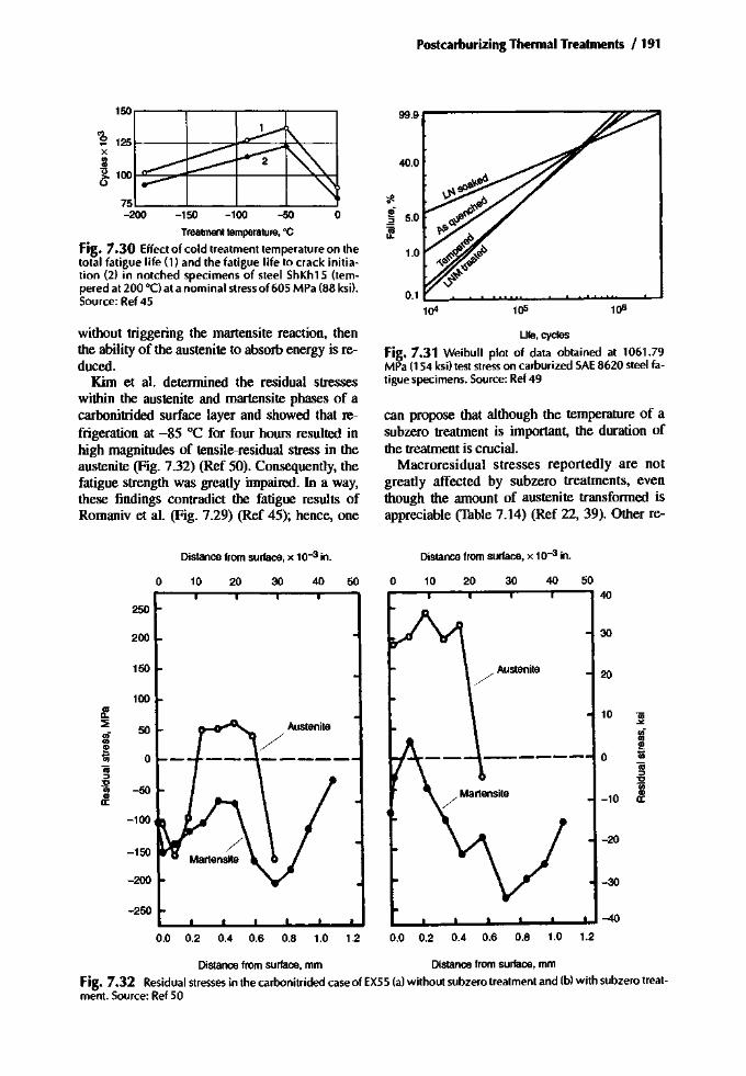
Postcarburizing Thermal Treatments /191
150,---,------r----,----,
Treattnent temperature, °C
Fig. 7.30 Effect of cold treatment temperature on thetotal fatigue life (l) and the fatigue life to crack initiation (2) in notched specimens of steel ShKh15 (tempered at 200°C) at a nominal stressof 605 MPa (88 ksi),Source: Ref 45
99.9
40.0
tf1.!!f 5.0.2f
1.0
0.11()4 105 1()6
without triggering the martensite reaction, thenthe ability of the austenite to absorb energy is reduced.
Kim et al. determined the residual stresseswithin the austenite and martensite phases of acarbonitrided surface layer and showed that refrigeration at -85°C for four hours resulted inhigh magnitudes of tensile-residual stress in theaustenite (Fig. 7.32) (Ref 50). Consequently, thefatigue strength was greatly impaired. In a way,these findings contradict the fatigue results ofRomaniv et al. (Fig. 7.29) (Ref 45); hence, one
Life.cycles
Fig. 7.31 Wei bull plot of data obtained at 1061.79MPa (154 ksi) test stresson carburized SAE8620 steel fatigue specimens. Source: Ref 49
can propose that although the temperature of asubzero treatment is important, the duration ofthe treatment is crucial.
Macroresidual stresses reportedly are notgreatly affected by subzero treatments, eventhough the amount of austenite transformed isappreciable (Table 7.14) (Ref 22, 39). Other re-
Distance from surface,x 10-3 in. Distance from surface, x 10-3 in.
o 10 20 30 40 50 o 10 20 30 40
250
200 30
15020
100
-30
-20
10
-10
o
/ Martensite/
L.......J_..J._....L._....._ .....- ..... -40
Austenite-:o
50
-50
-250
-150
-200
-100
0.0 0.2 0.4 0.6 0.8 1.0 1.2 0.0 0.2 0.4 0.6 0.8 1.0 1.2
Distance from surface. mm Distance from surface, mm
Fig. 7.32 Residual stresses in the carbonitrided case of EX55 (a) without subzero treatment and (b) with subzero treatment. Source: Ref 50
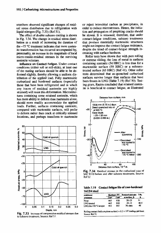
192 / Carburizing: Microstructures and Properties
-75
8!. 0::i;
13l!!lii -25
~1Il -50a:
-100o 0.05 0.1 0.15 0.2 0.25 0.3
Depth. mm
Fig. 7.33 Increase of compressive-residual stressesdueto subzero treatment. Source: Ref 51
o
3
.. •••.. ·Quenchedand cooled to-75 ·C twi -280
t.::i;
-After ufquenching ~
---Quenched -140and cooled to-75·C
Distance from surface. mm1 2
19.05 mm (0.75 in.) diam _ .........Direct quenched into oil ~ .' ....: ••••at 920 ·C I ..' +140
Casedepth I :'1.25-1.50 mm :(0.050-0.060 in.)
o
o
+20
AdditiouaJ Hardness,HV Iletaioed austenite Life,trealmeDt Core Case alsurface,'lI II
None 445 830 20--25 51LNG treated 445 810 10--12 40.5LNGplus150·C temper 443 865 No data 48
~ ~'\': ';,I: ':\I: ':, I:
-40 I': :.. ,.J.....~ °0
••••
L..;...._L-_..L1_H -l I _-L-40 80 100
Distance from surface. 10-3 in.
Fig. 7.34 Residual stresses in the carburized case ofSAE 9310 before and after subzero treatments. Source:Ref 52
Rollingcontact (ballson plane surface)=6.2 x I()5 loadingsperhour.Source:Ref 51
Table 7.19 Contact fatigue lifeof case-hardened16CD4steei
or reject interstitial carbon as precipitates, inorder to reduce microstresses. Hence, the initiation and propagation of prepitting cracks shouldbe slower. It is reasoned, therefore, that undercontact-fatigue conditions, subzero treatmentsthat produce essentially martensitic structuresmight not improve the contact-fatigue resistance,despite the trend of contact-fatigue strength increasing with surface hardness.
Roller tests have shown that with pure rollingor extreme sliding, the loss of metal in surfacescontaining austenite (54 HRC) is less than for amartensitic surface (59 HRC) or a subzerotreated surface (63 HRC) (Ref 41). Other rollertests determined that as-quenched carburizedsurfaces survive longer than surfaces that havebeen frozen in LNG (Table 7.19) (Ref 50). Testing gears, Razim concluded that retained austenite is beneficial to contact fatigue, as illustrated
./
t>VCold oil quench
~ /"f'O'
I r--...V~ VLNG--J
r---<\~ Cold oil quench
...............r-,- LNG-- ....
+25
BO
~ 60
I01 40
~! 20
o+50
searchers observed significant changes of residual stress distribution due to refrigeration withliquid nitrogen (Fig. 7.33) (Ref 51).
The effect of double subzero cooling is shownin Fig. 7.34. The change in residual stress distribution as a result of increasing the duration ofthe -75°C treatment indicates that more austenite transformation has occurred accompanied by,presumably, an increase in the magnitude of localmicro-tensile-residual stresses in the survivingaustenite volumes.
Influence on Contact Fatigue. Under contactconditions (either roll or roll-slide), at least oneof the mating surfaces should be able to be deformed slightly, thereby allowing a uniform distribution of the applied load. Fully martensiticcarburized and hardened surfaces (especiallythose that have been refrigerated and in whichany traces of residual austenite are highlystrained) will resist this deformation. Microstructures containing some retained austenite, whichhas more ability to deform than martensite alone,should more readily accommodate the appliedloads. Further, surfaces containing austenite,compared with martensitic surfaces, will preferto deform rather than crack at critically stressedlocations, and perhaps transform to martensite

Postcarburizing Thermal Treatments /193
structure, might not these have an adverse effecton the crack-initiation and growth times? And ifthe carbides observed to have precipitated underthe contact tracks differ (rj-carbides or monoclinic Hagg carbides) depending on whether ornot refrigeration has been used, might not suchdifferences have some significance?
Influence on Bending and Impact Toughness.Table 7.14 and 7.16 indicate how some toughness properties and the ductility are adversely influenced by refrigeration, though Fig. 7.29 indicates that the KIc fracture toughness may beimproved by a shallow refrigeration treatment.
Influence on Wear Resistance. In general,subzero treating a case-hardened surface to reduce the austenite content, and thereby raise thehardness, would be expected to have a positiveinfluence on the resistance of that surface toabrasive wear. However, roller tests indicated theopposite, and showed that as-quenched oras-quenched and tempered surfaces had approximately three times the wear resistance ofquenched and -50°C refrigerated surfaces (Table 7.20) (Ref 54). The changes in hardness andmatrix carbon content due to wear are far moredramatic in the refrigerated surfaces than in theothers. This potentially confirms that austenitesurviving a refrigeration treatment is destabilizedby the treatment and thereby responds morereadily to subsequent thermal and mechanicalactions (Fig. 7.25).
The adhesive wear situation, however, involvesmany factors and cannot adequately be coveredby generalizations. The alloy content of the steelis important. Some added elements (e.g., nickel)
60
500(4900) L-__~__-,-__---!
o
2500(24,500)
o 14CrNi14o 16MnCr5t.20MoCr4
2000(19,600)
~ 'iii2500
~
i! .~[ 0
'"1500 Co~ ~Cl (14.700) 2000 Clc: c:.~
.~~"0 1500 "0
'" 1000 '"0 0...J(9800) ...J
1000
20 40Retainedaustenite, %
Fig. 7.35 Gear test results show that within the conditions of the tests, the load carrying capacity increasedwith retained austenite content. Source: Ref 53
in Fig. 7.35 (Ref 53). In this study, refrigerationwas used to arrive at essentially zero retainedaustenite within the cases of some of the testgears. From such a test it is not clear how muchof the difference between the results for refrigerated gears (containing small amounts of austenite) and the results for as-quenched gears (containing, say, 30% austenite) is due to thediscrepancy in austenite contents and how muchof that difference is due to other effects ofsubzero treating. If refrigeration produces localtensile microstresses in the resultant micro-
Table7.20 Results of slide/rollwear tests on 12KhN3AsteelWear,mg
LoadinB cycles IIanIDess, HV Carbon iDmarteDSite, % Small roller Larxe roller
Carburized at 1000 "C to a depth of 1.8 mm; oil quenched from 900 "Cand 800 "Co(before test) 792 0.601 x 10⁶ 760 0.55 60 682 x 106 758 0.41 68 753 x 106 738 0.49 74 90
Carborized at 1000 °C to a deptb ofl.8 mm; oilquencbed from 900 "C and 800 "C; tempered at 230 "C for 5 bo(before test) 679 0.501 x 10⁶ 697 0.31 18 522 x 106 758 0.32 39 853 x 106 729 0.39 45 126
Carborized at 1000 "Cto a depth of 1.8 mm; oil quenched from 900 "Cand 800 "C; refrigerated at -so "Cfor 1 bo(before test) 763 0.691 x 10⁶ 517 0.25 120 2622 x 106 597 0.35 140 2873x 106 619 0.32 170 353
Testsconducted at 12.400 kglcm2contact pressure. Testpieces wer temperedat 650 "Cfor 4 b betweencarburizing and hardening. Source:Ref 54

194 / Carburizing: Microstructures and Properties
tend to increase the susceptibility of a surface toadhesive wear (scoring, scuffing) more so, it isclaimed, than a high austenite content does (Ref55). Even so, retained austenite does have an effect. Friction tests on a carburized 4%NiCr steelwith either 5 or 25% retained austenite showedthat the coefficient of friction (Jl) of the 5% austenite surface stayed fairly constant over the temperature range of the tests, whereas the Jl value forthe sample with 25% austenite rose appreciably at160 °C (Ref 56). This implies that under certainconditions (e.g., pressure, temperature, speed, andlubrication), a higher austenite content can favoradhesive wear; therefore refrigeration might havea beneficial effect.
Unfortunately, laboratory tests seem to produce conflicting results when it comes to assessing the effects of retained austenite. Kozlovskiiet al. found that a surface containing approximately 50% retained austenite has a superior resistance to seizure when compared to a surfacecontaining less than 20% retained austenite (Fig4.28) (Ref 57). Seizure tests by Manevskii andSokolov showed that the scoring resistance was,to some extent, hardness related; for the hardestsurface tested (-700 H1(0) the scoring resistancewas less than it was for a softer surface (-600H lOo). Terauchi and Takehara observed the opposite trend (Fig. 4.29) (Ref 59).
For gears, adhesive wear relates to the conditions prevailing during rolling with sliding contact under pressure; generally a designer can estimate if a design has a tendency to score inservice. It is not certain if laboratory tests can adequately simulate real-life conditions, althoughNaruse and Haizuka claim that the limiting loadfor scoring by means of the FZG spur gear test,the four-ball test, and disk tests could be compared (Ref 60). Without resorting to the metallurgy of the test pieces, they concluded that thelimiting load for scoring is a function of slidingvelocity, specific sliding, and the type of lubricant used.
When scoring occurs on gear tests, it is usually high on the tooth addenda at the point ofdisengagement where the amount of sliding ishigh. Therefore, if a design is considered proneto scoring, lubricant choice is important, and"running-in" to precondition the surface is advisable to remove asperities that might otherwise penetrate the lubricating film thickness athigher pressures, and to induce work hardeningof the mating surfaces. Thus, the ability of asurface to work harden is significant, but it must
be given the opportunity to work harden without an excessive surface temperature rise thatcould lead to scoring. If refrigeration reducesthe capacity of a surface to work harden or toshed its asperities, then in certain situations itcould be regarded as detrimental.
Retained Austenite Standards. It has beenstated before, and is restated here, that it isbetter to manage other process variables to control retained austenite before resorting to refrigeration. Some laboratory tests have indicatedthat high austenite contents are beneficial,whereas others conflict with that view. For thetime being, the gear industry, through tests andexperience, has chosen to restrict the acceptableamount of retained austenite to 25% (ISO6336-5) or 30% (AGMA 2001-C95) for all butthe lowest grade of commercially carburizedgear. That said, if the basic allowable stressesused by designers can be regarded as generousenough to include parts in the refrigerated condition, then it is the decision of the manufacturer whether or not to use the subzero process(unless specified), provided the recommendedmaximum for retained austenite is not exceededand the surface hardness is adequate. Note thataerospace and marine gears (AGMA246-02[1983] and AGMA 6033) permit up to20% retained austenite on the highest ratedgears.
Summary
Tempering
Most case-hardened parts are tempered at atemperature above 130°C (265 "F) but rarely exceeding 250°C (480 "F). The most commontempering temperature is about 180 °C (350 "F).At this temperature, any austenite in the case isaffected only a little. At higher tempering temperatures, some austenite transforms to bainite;this is not necessarily beneficial. Temperingtimes are usually from 2 to 10 h, depending onthe size of the component and the structural stability required. Such tempering, in additon toprecipitating coherent carbides and reducing thetetragonality of the martensite, also drives off hydrogen taken up during the case-hardening process.
• Preprocess considerations: None• In-process considerations: If intermediate
machining is to be carried out to locally re-
move case, then a high-temperature temper(or anneal) is used to impart adequatemachinability. The temperatures for this are inthe range of 600 to 650°C (1110 to 1200 "F),
• Post-process considerations: Low-temperaturetempering is done after hardening; however, itshould be repeated after refrigeration (ifused). A repeat low-temperature temper shouldbe considered if the surface is still exceptionally hard after the initial temper. Some manufacturers temper after grinding.
• Effect on properties: Low-temperature tempering reduces the hardness into the normallyaccepted range of 58 to 62 HRe. It reducesthe surface compressive-residual stresses and,therefore, lowers the high-cycle bendingfatigue strength, and it is thought to improvethe low-cycle bending strength. In terms ofrolling-contact fatigue, tempering is believedto raise the high-cycle fatigue life, but mayhave an adverse effect on the low-cycle endurance. The hardness-strength properties ofthe core are affected only a little by tempering, although the yield strength is raised.
• Standards: The ANSI/AGMA standard hasno tempering specification for grade 1, butrecommends tempering for grade 2 and requires it for grade 3.
Refrigeration
Case-hardened parts are refrigerated to transform retained austenite in the outer case. Thisraises the surface hardness and induces structuralstability. Refrigerants available for the subzerotreatment of heat-treated parts are dry ice (solidCO2) and liquid nitrogen gas (LNG). Temperatures down to about -80°C (112 "F) are achievable with CO2, whereas temperatures of -196°C(-320 "P) are possible with LNG refrigeration. Itis not normal to place heat-treated parts intoLNG; rather LNG is used to chill a compartmentto whatever temperature is considered reasonablefor the job, say -80°C or even -120°C.
• Preprocess considerations: Refrigeration iscarried out after the quenching operation; itgenerally follows the initial tempering operation. It is prudent to allow parts to cool toroom temperature before subjecting them tosubzero temperatures. Hardness test beforetreatment.
• In-process considerations: Record the minimum temperature and the duration of the process.
Postcarburizing Thermal Treatments /195
• Postprocess cosiderations: It is advisable toretemper soon after the part has attained roomtemperature. Perform a hardness test after refrigeration, and if the part is still soft after refrigeration, then other possible reasons for thesoftness must be considered.
• Effect on properties: Refrigeration transformscase austenite to martensite, which raises thehardness. It also raises the surface macrocompressive-residual stresses, but inducesmicroresidual tensile stresses in any remaining austenite volumes. Tests to determine theeffect of refrigeration on bending fatigue haveproduced mixed results; the steel grade, thesubzero temperature, and the duration of refrigeration can all influence the results. Contact fatigue and case ductility each appear tobe adversely affected by the process. Refrigeration, coupled with tempering, is nonetheless a valuable process where dimensionaland microstructural stability are important.
• Standards: ANSI/AGMA permit refrigerationfollowing the tempering operation, and it isfollowed by a retemper. The purpose is to obtain a 1 to 2 HRC increase of hardness. Refrigeration to transform high amounts of retainedaustenite (say 50%) should not be considered,as this might cause microcracking.
REFERENCES
1. GR Speich and w.e. Leslie, Tempering ofSteels, Met. Trans., Vol 13, May 1972, p1043-1054
2. H.-J. Zhou and YJ. Li, Low CarbonMartensites and Their Application, Proc. 6thInt. Congress on Heat Treatment of Metals(Chicago), ASM International, 1988
3. P.M. Kelly and J. Nutting, The martensitetransformation in carbon steels, Proc. R. Soc.(London) A, Vol 259, 1960, P 45-58
4. S. Nagakura, Y. Hirotsu, M. Kusonoki, T.Suzuki, and Y. Nakamura, CrystallographicStudy of the Tempering of Martensitic CarbonSteel by Electron Microscope and Diffraction,Metall. Trans. A, Vol 14, June 1983, p1025-1031
5. I.Y. Kagan, S.Y. Bronin, and I.Y. Sidorenko,Tempering of Quenched Carbon Steels, Met.Sci. Heat Treat. (USSR), No.1, JanlFeb 1964, p87-91
6.0. Yasuya and T. Imao, Epsilon Carbide Precipitation During Tempering Plain Carbon
196 I Carburizing: Microstructures andProperties
Martensite,Metall. Trans. A, Vol23, Oct 1992,p2737-2751
7. E.I. Mittemeyerand F.C.VanDoorn,Heat Effectsof Pre-Precipitation Stageson Temperingof Carbon Martensites, Metall. Trans. A, Vol14,May 1983,p 976-977
8. Y.Nakamura,T. Mikami, and S. Nagakura,InSitu High Temperature Electron MicroscopeStudy of the Formation and Growth ofCementiteParticlesof the Third Stageof Tempering of Martensitic High Carbon Steel,Trans. Jpn: Inst. Met., Vol 26 (No. 12), Dec1985,p 876-885
9. C.-B. Ma, T. Ando, D.L. Williamson, and G.Krauss, Chi-Carbide in Tempered High Carbon Martensite, Metall. Trans. A, Vol14, June1983,p 1033-1044
10.Y Imai,T. Oguro, and A Inoue,FormationofX-Carbide in Carbon Steel, Tetsu-to-Hagane(llron Steel Inst. lpn.), Vol57 (No.4), 1971,Sll3-S114
II. R.w. Neu and H. Sehitoglu, Thermal InducedTransformation of Retained Austenite in theSimulatedCase of a CarburisedSteel,1 Eng.Mater. Technol. (Trans. ASME), Vol 115, Jan1993,p 83-88
12.J.L. Aston, The Influenceof Tempering TImeon Someof theMechanicalandPhysicalProperties of Steel, Bull. Jpn. Inst. Met., Vol 192(No.4), Aug 1959,P 377-382
13.H. Streng,C. Razim, and J. Grosch, Influenceof Hydrogenand Tempering on the Toughnessof Case Hardened Structures, Carburising:Processing and Performance (Lakewood,CO), G. Krauss,Ed., ASM International Conference, 1989
14.L. Salonen,The ResidualStress in CarburisedLayers,Acta Polytech. Scand., Vol109,1972,p7-26
15.V.V. Zabil'ski, VI. Sarrak, and S.D. Suvorova,The Role of RelaxationProcesseson the Volume Change Occurringin SteelsDuringTempering, Fiz: Met. Metalloved; Vol 48 (No.2),Aug 1979,P 323-331
16.K.I. Irvine, F.B. Pickering, and J. Garstone,The Effect of Composition on the Structureand Properties of Martensite, Bull. Jpn. Inst.Met., Vol196,Part1, Sept 1960,p 66-81
17.VV.Babayan,Low-Temperature Tempering ofCarburized and Hardened Steel 30KhGT,Metalloved. Term. Obrab. Met., Aug 1959, p41-43
18.G. Meyer, The Influenceof HeatTreatmentonthe Structure and Mechanical Properties of
Carburised Steels, Conf. on Heat TreatmentPractice, July 1960 (Harrogate), BISRA, p13-23
19.G. Parrish and G.S. Harper, Production GasCarburising, Pergamon, 1985
20.AG. Ran'kova, V.S. Kortov, ML Khenkin,AI. Saprindashvili, and G.M. Guseva, Stability of the Surface Layer of Bearing SteelShKh15,Met. Sci. Heat Treat. (USSR), (No.6),June 1975,p 71-73
21.P.M. Vogel, Alignment of Case-HardenedParts, Carburising: Processing and Performance (Lakewood, CO), G. Krauss,Ed., ASMInternational Conference, 1989
22. D.A Sveshnikov, LV Kudryavstev, N.A.Gulyaeva, and L.D. Golubovskaya,Chernicothermal Treatmentof Gears,Met. Sci.Heat Treat. (USSR), (No.7), July 1966, P527-532
23. M. Motoyamaand S. Yonetani, On the Influence of Tempering and Hydrostatic Pressingon the Residual Stress of Carburised andQuenchedSteel,1 Jpn. Inst. Met., Vol33 (No.1), 1969,P 109
24. D. Kirk, P.R. Nelms, and B. Arnold, ResidualStresses and Fatigue Life of Case-CarburisedGears, Metallurgia, Vol 74 (No. 446), Dec1966,P 255-257
25.H. Weigand andG.Tolasch, FatigueBehaviourof Case-Hardened Samples,Han-Tech. Mitt.,Vol22 (No.4), Dec 1967,P 330-338
26.R.I. Love, uc Allsopp, and AT. Weare, ''TheInfluence of Carburising Conditions and HeatTreatment on theBendingFatigueStrength andImpact Strength of Gears made from En352Steel," MIRAReport 1959n, 1959
27.C.Q. Gu, B.Z. Lou, X.T. Jing, and F.S.Shen, Microstructures and MechanicalProperties of the Carburised CrNiMoSteels with Added Case Nitrogen, Proc.6th Int. Congress on Heat Treatment ofMetals (Chicago), ASM International,1988
28. G. Fett, Bending Properties of CarburisingSteels,Adv.Mater. Proc., Vo14, 1988,p 43-45
29.C. Razim, Influenceof Residual AusteniteontheStrengthProperties of Case-Hardened TestPiecesDuringFatiguing,Han. -Tech.Mitt., Vol23, April 1968,P 1-8
30.D. Rosenblatt, Controlling Variables WhichAffectthe Tempering of CarburisedGears,4thInt. Congress on Heat Treatment ofMaterials,IFHT,1985

31. D.E. Diesburg and C. Kim, Microstructuraland Residual Stress Effects on Impact Fracture Resistance of Carburised Cases, 5thASM Heat Treating Con! and 18th Int.Con! On Heat Treating ofMaterials, ASM,1980
32. M.M. Shea, Influence of Quenchant Temperature on the Surface Residual Stresses and Impact Fracture of Carburised Steel, J. HeatTreat., Vol 3 (No.1), June 1983, p 38-47
33. B. Thoden and J. Grosh, Crack Resistance ofCarburised Steel Under Bending Stress, Carburising: Processing and Performance(Lakewood, CO), ASM International Conference, 1989, p 303-310
34. G. Fett, Tempering of Carburised Parts, Met.Prog., Sept 1982, p 53-55
35. H.K. Obermeyer and G. Krauss, Toughnessand Intergranular Fracture of a Simulated Carburised Case in Ex 24 Type Steel, J. HeatTreat., Vol 1 (No.3), June 1980, p 31-39
36. J. Larsen-Badse, The Abrasion Resistance ofSome Hardened and Tempered Carbon Steels,Trans. Metall. Soc. AlME, Vol 236 (No. 10),Oct 1966, P 1461-1466
37. X. Yaomin and F. Dongli, HydrogenEmbrittlement of Steels Heat Treated in Hydrogen Rich Atmosphere, Proc. 6th Int. Con!On Heat Treatment ofMetals (Chicago), ASMInternational, 1988
38. H. Streng, C. Razim, and J. Grosch, Diffusionof Hydrogen During Carburising and Tempering, Proc. 6th Int. Conf. On Heat Treatment of Metals (Chicago), ASM International, 1988
39. I.S. Dukarevich and M.A Balter, Thermomechanical Treatment in Hydrogen-ContainingAtmospheres Improves Carburised-SteelQualities, Russ. Eng. J.,Vol53 (No.8), 1973, P62-65
40. 1 Cesarone,IncreasingHardnessThroughCryogenics,Gear Technol., March 1997,P 22-27
41. M.A. Balter and M.L. Throvskii, Resistance ofCase-Hardened Steel to Contact Fatigue, Met.Sci. Heat Treat. (USSR), (No.3), March 1966,p 177-180
42. D.P. Koistinen and RE. Marburger, A GeneralEquation Prescribing the Extent of theAustenite-Martensite Transformation in PureIron-Carbon Alloys and Plain Carbon Steels,Acta Metall., Vol 7, 1959, P 59-60
43. M.A. Balter and I.S. Dukarevich, The Relationship Between the Properties of SteelsSubjected to Chemicothermal Treatment
Postcarburizing Thermal Treatments /197
and the Fatigue Limit, Met. Sci. Heat Treat.(USSR), Vol 13 (No.9), Sept 1971,p729-732
44. E. Szpunar and 1 Birelanik, Influence of Retained Austenite on Properties of FatigueCracks in Carburised Cases of Toothed Elements, Proc. Heat Treating 1984, The MetalsSociety, London
45.0.N. Romaniv, YN. Gladkii, and N.A. Deev,Some Special Features of the Effect of Retained Austenite on the Fatigue and CrackingResistance of Low-Temperature TemperedSteels, Fiz. Khim. Mekh. Mater.,Vol 11 (No.4),1975, P 63-70
46. M.A Zaccone and G. Krauss, Fatigue andStrain Hardening of Simulated Case Microstructure in Carburised Steel, Proc. 6th Int.Congress on Heat Treatment of Metals (Chicago), ASM International, 1988
47. lG. Roberts and RL. Mattson, Fatigue Durability of Carburized Steel, American Societyfor Metals, 1957, P 68-105
48. M.A Panhans and R.A. Fournelle, HighCycle Fatigue Resistance of AI.S.I., E.9310 Carburised Steel with Two DifferentLevels of Retained Austenite and SurfaceResidual Stress, J. Heat Treat., Vol 2 (No.1),1981, P 56-61
49. lD. Collins, The Effects of Low Temper Magnetic Cycling on the Properties of Ferromagnetic Materials, J. of Eng. Mater. Technol.(Trans. ASME), Vol 102, Jan 1980, p 73-76
50. C. Kim, D.E. Diesburg, and RM. Buck, Influence of Sub-Zero and Shot-Peening Treatments on Impact and Fatigue Fracture Properties of Case-Hardened Steels, 1 Heat Treat.,Vol2 (No.1), June 1981, p 43-53
51. A Diament, R EI Haik, R Lafont, and RWyss, "Surface Fatigue Behaviour of theCarbo-Nitrided and Case-Hardened Layers inRelation to the Distribution of the ResidualStresses and the Modifications of the CrystalLattice Occurring During Fatigue," 15thColloque Int., May 1974 (Caen, France), International Federation for the Heat Treatment ofMaterials
52. W.S. Coleman and M. Simpson, ResidualStresses in Carburized Steels, FatigueDurability of Carburized Steel, American Society forMetals, 1957, p 47-67
53. C. Razim, Effect of Residual Austenite andReticular Carbides on the Tendency to Pittingof Case-Hardened Steels, thesis, TechnischeHochschule, Stuttgart, 1967

198 / Carburizing: Microstructures and Properties
54. L.Y. Oshinya and VA Grishko, Effect of HeatTreatment on Changes in the Properties of theSurface Layer of Steel 12Kh N3A DuringWear, Met. Sci. Heat Treat. (USSR), (No.4),April 1973
55. R.M. Matveevskii, V.M. Sinaisky, and LA.Buyanovsky, Contributions to the Influenceof Retained Austenite Content in Steels onthe Temperature Stability of Boundary Lubrication Layers in Friction, I. Lubr. Technol.(Trans. ASME), July 1975,P 521-525
56. W. Grew and A. Cameron, Role of Austeniteand Mineral Oil on Lubricant Failure, Nature,Vol 217 (No. 5127), 1968, P 481-482
57. I.L Kozlovskii, S.E. Manevskii, and LLSokolov, Effect of Retained Austenite on theResistance to Scoring of Steel, 20Kh2N4A,Met. Sci. Heat Treat. (USSR), (No.1), 1978,p7~80
58. S.E. Manevskii and I.I. Sokolov, Resistance toSeizing of Carburised and Carbon NitridedSteels, Metalloved. Term. Obrab. Met., (No.4),April 1977, P 66-68
59. J. Terauchi and J.I. Takehara, On the Effect ofMetal Structure on Scoring Limit, Bull. Jpn.Soc. Mech. Eng., Vol21 (No. 152),Feb 1978, p
324-33260.A. Naruse and S. Haizuka, Limiting Loads for
Scoring and Coefficient of Friction on DiskMachines, Bull. Jpn: Soc. Mech. Eng., Vol 21(No. 158), Aug 1978, P 1311-1317
SELECTED REFERENCES
• A. Jordine, Increased Life of Carburised RaceCar Gears by Cryogenic Treatment, Mater.Aust., Vol 27 (No.7), Aug 1995, P8-10
• A. Jordine, Increased Life of Carburised RaceCar Gears by Cryogenic Treatment, IMMAConference "The Heat Is On!" 24-25 May1995 (Melbourne, Victoria, Australia), Institute of Metals and Materials Australasia Ltd.,1995, P 107-111
• R.E Spitzer, H.A. Chin, and DA Haluck,Cryogenic Thrbopump Bearing Material Development Program, Conf.: Creative Use ofBearing Steels, 6-8 Nov 1991 (San Diego),STP 1195, ASTM, 1993, P 156-167
• B. Vinokur, The Isothermal Diagram ofTransformation of the Residual Austenite byTempering, Metall. Trans. A, Vol 24 (No. 12),Dec 1993, p 2806-2810

Chapter 8
PostcarburizingMechanical Treatments
The mechanical treatments most commonlyapplied to case-hardened parts are shotpeening and surface grinding, as well as rollerburnishing to a very much lesser degree. Shotpeening and roller burnishing plastically deform and texturally modify the surface and induce compressive residual stresses, therebyimproving the fatigue resistance of the treatedpart. Parts are ground to obtain dimensionalaccuracy and to replace the heat-treated finishwith one that is both clean and smooth. Theprocess parameters for each of these mechanical treatments are controlled within fairly narrow, though not unreasonable, limits, and whencorrectly executed, these processes are beneficial to the parts treated. If, however, the processes are not carried out correctly they can adversely influence properties.
Grinding
When components are case hardened, somegrowth and distortion (size and shape changes)can be expected to occur as a result of the thermal processing. For example, with gears, thegear teeth themselves may thicken, diametersmay increase or decrease, and worm threadsmay unwind. Squat cylinders may "barrel,"and long cylindrical shapes may do the opposite. In their process schedules, manufacturersinclude measures that allow for such movements or contain them within tolerable levels,then correct the critical dimensions by grinding.
Besides restoring precision, grinding is alsoemployed to remove the heat-treated surface. Italso removes any potentially detrimental metallurgical features, such as carbide films, internaloxidation, and high-temperature transformationproducts (HTIP) that can otherwise adverselyaffect certain strength aspects of the component.Grinding for surface finish is important, becauseit too can influence the bending and contact fatigue lives of a component and the efficiencyof alubricant to separate mating surfaces.
Grinding Action
During gentle grinding (when the depth of cutand thrust forces are low), a particle of abrasiveprotruding from the working surface of thegrinding wheel ploughs into the surface of thecomponent, which produces a furrow. In deformable workpiece materials, the furrow is formedmainly by the displacement of metal from belowand to either side, producing heaped edges (Ref1). A second abrasive particle, slightly offset tothe first, ploughs into one heaped furrow edge.This contact displaces metal and adds more deformation to an already plastically deformed material, and it possibly removes some metal particles by shear from the common edge betweenthe two furrows. When ploughing is the main occurrence, the metal removal rate is low. Withgreater amounts of feed (depth of cut), metal isremoved directly from the workpiece surface aschips without involving much ploughing. Themetal removal rate under such conditions is high.
Carburizing: Microstructures and Properties Copyright © 1999 ASM International® Geoffrey Parrish, p 199-225 All rights reserved. DOI: 10.1361/cmap1999p199 www.asminternational.org

200 / Carburizing: Microstructures and Properties
The ploughing or chipping action takes placesimultaneously many times across a contact areabetween the workpiece and the grinding wheeland thousands of times during each wheel revolution. Acknowledging that the grinding wheelrotates at thousands of revolutions per minute, anappreciable amount of high-rate deformationtakes place during grinding along with the generation of heat caused by that deformation. Not allthe deformation and heat generated is producedby the furrowing and chipping action. The grit ofthe grinding wheel protrudes for only a limiteddistance from its bond and, therefore, rubbingand rolling actions by bond contact also producedeformation and heat. Further, as the grit of thewheel becomes duller or more loaded with attached metal debris and, therefore, more in needof a dressing operation, the amount of metal removed from the workpiece decreases, but theheat generation caused by friction increases.
Therefore, much of the energy used in thegrinding action is converted into heat, and thisheat is dissipated by conduction into theworkpiece, the coolant (if used), and the abrasive. The heat is also carried away in the detached incandescent metallic particles that arecontinuously ejected from the wheel/workpiececontact zone. For successful grinding of materials having some measure of ductility, the objective should be to control the heat and ensure thatthe final surface is lightly plastically deformed.
Hard materials generally have little ability tobe deformed, and the displacement of metal toform heaps at the sides of a furrow does not occur. Instead, for such materials, small cracks mayradiate from the grinding furrow, even whengrinding conditions are carefully controlled (Ref2). This cracking is attributed primarily to mechanical causes. If some of the heat generated atthe surface by the grinding action dissipates intothe workpiece surface and thereby reduces theyield strength at the surface, then cracking at thefurrow edges is eliminated. Mikhailov (Ref 2)suggested that the millions of variable loadingsto which a workpiece surface is subjected duringgrinding cause the breakdown of the surface material at lower stresses. The mechanism for howthis breakdown occurs is not clear. It could involve "crumbling" of the cracked furrow edgesor a lowering of the surface yield strength.
Case-hardened surfaces are generally regardedas being hard and essentially brittle. However,such surfaces have the ability to be deformed(see the sections "Roller Burnishing" and "ShotPeening" in this chapter). Therefore, the martensite!
austenite aggregate, typical of a case-hardenedsurface, should be regarded as being deformablewith respect to grinding. Carbides within acase-hardened surface, on the other hand, areconsidered hard materials.
GrindingBurns and Cracks
By far the most common problem duringgrinding is a loss of control of the heat generatedat the surface by the abrading action. This occurrence may be caused by not replacing or not renovating the grinding wheel at the correct time, byusing the wrong grade of wheel, or perhaps byremoving too much stock at each grinding pass.If the heat generated at a carburized surface isgreat and is not transferred away to any significant extent, then the temperature of the surfacerises to a level sufficient to induce tempering ofthe predominantly martensitic surface. Such local tempering is termed "overtemper burning."The hardness of an overtemper bum area is generally several equivalent HRC points lower thanthat of an unburned area. The extent depends onthe temperature and the duration of heating. Inaddition, because tempering involves the precipitation of carbides (accompanied by a volumecontraction), the local tempered areas are in astate of reduced residual compression or possiblyin a state of residual tension.
However, if during grinding the surface temperature exceeds the AC3' thereby producing athin layer of austenite, then because of the largeheat-sink effect of the component, the austeniterapidly cools to give a hard, light-etching martensite. Such an induced defect is known as a "rehardening burn." Because a thermal gradient mustexist between the zone that is made austeniticand the underlying material, such a rehardeningbum must be surrounded by an intermediatelayer of overtempered material (Fig. 8.1) and ofreduced hardness (Fig. 8.2). Reasoning suggeststhat the rehardened zone should be in residualcompression due to the martensitic expansion,while the adjacent tempered areas should experience residual tension. However, at the instant ofburning and just after, the surface is subjected toappreciable mechanical forces via the action ofthe grinding wheel (the surface may even be ruptured by the force). Therefore, it is possible thatmechanically induced surface stresses significantly influence the eventual residual stress distribution associated with a burn. Consequently, itis difficult to predict the final residual stress distribution in a burn area.

800
o0
ACl~:::le'" 600a.E~
400
200
Postcarburizing Mechanical Treatments / 201
.:~-._~I;;U;;M.C~
I
11- - Depth of rehardened burn
IIIIII
Austenitizing temperature(Acl plus)
II Depth of retempered burn
III
- Original tempering temperature
00 0.002 0.004 0.006 0.008 0.01
Depth from surface, in., I , I
0 0.05 0.10 0.15 0.20 0.25
Depth from surface, mm
Fig. 8.1 Temperature distribution within a ground surface as indicated by microstructural modifications. The Ac temperature indicated is for slow heating; at high heating rates, e.g., in a grinding pass, the Ac temperatures will be elevated.Note: high-speed heating raises Ac temperatures. Micrograph, 500x
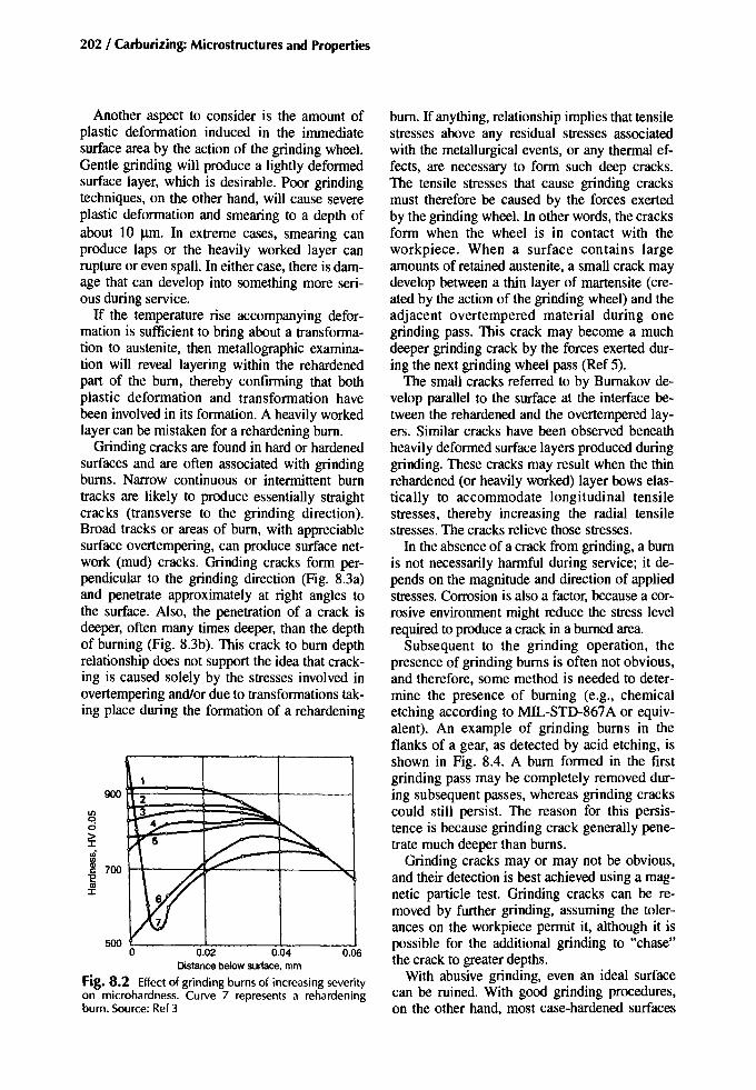
202 / Carburizing: Microstructures and Properties
bum. Ifanything, relationship implies that tensilestresses above any residual stresses associatedwith the metallurgical events, or any thermal effects, are necessary to form such deep cracks.The tensile stresses that cause grinding cracksmust therefore be caused by the forces exertedby the grinding wheel. In other words, the cracksform when the wheel is in contact with theworkpiece. When a surface contains largeamounts of retained austenite, a small crack maydevelop between a thin layer of martensite (created by the action of the grinding wheel) and theadjacent overtempered material during onegrinding pass. This crack may become a muchdeeper grinding crack by the forces exerted during the next grinding wheel pass (Ref 5).
The small cracks referred to by Bumakov develop parallel to the surface at the interface between the rehardened and the overtempered layers. Similar cracks have been observed beneathheavily deformed surface layers produced duringgrinding. These cracks may result when the thinrehardened (or heavily worked) layer bows elastically to accommodate longitudinal tensilestresses, thereby increasing the radial tensilestresses. The cracks relieve those stresses.
In the absence of a crack from grinding, a bumis not necessarily harmful during service; it depends on the magnitude and direction of appliedstresses. Corrosion is also a factor, because a corrosive environment might reduce the stress levelrequired to produce a crack in a burned area.
Subsequent to the grinding operation, thepresence of grinding bums is often not obvious,and therefore, some method is needed to determine the presence of burning (e.g., chemicaletching according to MIL-STD-867A or equivalent). An example of grinding bums in theflanks of a gear, as detected by acid etching, isshown in Fig. 8.4. A bum formed in the firstgrinding pass may be completely removed during subsequent passes, whereas grinding crackscould still persist. The reason for this persistence is because grinding crack generally penetrate much deeper than bums.
Grinding cracks mayor may not be obvious,and their detection is best achieved using a magnetic particle test. Grinding cracks can be removed by further grinding, assuming the tolerances on the workpiece permit it, although it ispossible for the additional grinding to "chase"the crack to greater depths.
With abusive grinding, even an ideal surfacecan be ruined. With good grinding procedures,on the other hand, most case-hardened surfaces
500 ~ ~;;-__---:~ -::-!
900 2ltlq0
>:I:iii
'"~ 700"Eas:I:
0.02 0.04 0.06Distancebelowsurface. mm
Fig. 8.2 Effect of grinding burns of increasing severityon microhardness. Curve 7 represents a rehardeningburn. Source: Ref3
Another aspect to consider is the amount ofplastic deformation induced in the immediatesurface area by the action of the grinding wheel.Gentle grinding will produce a lightly deformedsurface layer, which is desirable. Poor grindingtechniques, on the other hand, will cause severeplastic deformation and smearing to a depth ofabout 10 um. In extreme cases, smearing canproduce laps or the heavily worked layer canrupture or even spall. In either case, there is damage that can develop into something more serious during service.
If the temperature rise accompanying deformation is sufficient to bring about a transformation to austenite, then metallographic examination will reveal layering within the rehardenedpart of the bum, thereby confirming that bothplastic deformation and transformation havebeen involved in its formation. A heavily workedlayer can be mistaken for a rehardening burn.
Grinding cracks are found in hard or hardenedsurfaces and are often associated with grindingbums. Narrow continuous or intermittent bumtracks are likely to produce essentially straightcracks (transverse to the grinding direction).Broad tracks or areas of bum, with appreciablesurface overtempering, can produce surface network (mud) cracks. Grinding cracks form perpendicular to the grinding direction (Fig. 8.3a)and penetrate approximately at right angles tothe surface. Also, the penetration of a crack isdeeper, often many times deeper, than the depthof burning (Fig. 8.3b). This crack to bum depthrelationship does not support the idea that cracking is caused solely by the stresses involved inovertempering and/or due to transformations taking place during the formation of a rehardening

can be ground without burning. However, microstructural features other than martensite presentat the surface contribute to the degree of difficulty in achieving (or reestablishing) the correctgrinding parameters. What is optimal for grinding martensite is not optimal for grinding austenite, bainite, and ferrite.
Effect ofGrinding Variables
There is little reported work on the effect ofgrinding variables on residual stresses in casehardened surfaces. However, a fair amount of in-
(8)
Postcarburizing Mechanical Treatments / 203
formation is available concerning throughhardened steels.
Influence on Depth of Cut (Feed). Increasingthe depth of cut increases the depth to whichthe surface metal is deformed and in whichheat is generated. In consequence, the depth ofpenetration of the ensuing residual stress distribution is also increased (Fig. 8.5). Excessivedown feeds and cross feeds can cause burningand cracking.
Influence on Wheel Peripheral Speed. Schreiber(Ref 3) determined that wheel speed has nosignificance on residual stresses developedwithin a ground surface. Gormly (Ref 6), on theother hand, reported that a reduction of wheelspeed causes a reduction of residual stresses,presumably because less heat is generated in theworkpiece surface, which results in a reducedtempering effect. Conversely, a slower peripheralspeed can lead to an inferior ground surface finish. It is considered more favorable to employ asofter wheel, because soft wheels tend to wearmore readily, which exposes fresh abrasive cutting edges, and the residual stresses are confinedmore to the surface and to a lower magnitude.
Influence on Workpiece Speed. Within limits,an increase of workpiece speed can be beneficial,because it improves the feed of coolant, if used,into the wheel/workpiece contact zone. The contact time is reduced, and the quantity of heat removed is greater (Ref 3).
(b)
Fig. 8.3 Examples of grinding cracks. (a) Cracks on the flank of a worm thread . (b) Micrograph of grinding cracks incase-hardened 8620 steel showing several small cracks (arrows at right) that extended through the hardened case to thecore , and the burned layer on surface (dark band indicated by arrow atleftl that resulted from grinding burns. Note: nitaland acidic ferric chloride are suitable etchants for grinding burns . Source : Ref4

204 / Carburizing: Microstructures and Properties
-275
275
275
275
550
275
-2758!.~
550 gi
~
-275
8
0.2
BarNo.206Down Ieed = 0.002 in.
= 0.05 mm
BarNo.205Downfeed= 0.001 in.
= 0.025 mm
BarNo.203Down Ieed = 0.0001 in.
=0.0025 mm
BarNo.204Down Ieed = 0.0005 in.
=0.0125mm
Depth, mm
0.1
o
o
-40
-40
-40~
~l!? 80iii
Depth, 10-3 in.
Fig. 8.5 Effect of depth of cut on residual stress distribution. Source: Ref 6
grades G, H, or even I may be used. The hardness of a wheel influences its self-sharpeningcharacteristics. If the wheel surface loses abrasive particles during grinding, the bond mustquickly wear away to expose fresh abrasive particles. Alternatively, if the abrasive particles become worn (dulled) by grinding, the bond mustdisintegrate (under the pressure of grinding) toexpose fresh abrasive particles.
Fig. 8.4 Grinding cracks on the flanks of a small spurgearwheel.
Influence on Wheel Grit and Hardness. Wheelselection for grinding is governed by theamount of stock to be removed from theworkpiece surface and the quality of finish required. Two important wheel characteristics toconsider are grit size and wheel hardness. Thegrit size (given as a number) quantifies thecoarseness of the abrasive, whereas hardness(specified by a letter) refers to the hardness ofthe bond holding the grit.
Where relatively large amounts of stock are tobe removed, a coarse grit wheel can be used initially, followed by a fine grit wheel to obtain thesurface finish and size required. Finishing passesshould remove any defects (assuming no cracks)induced by the roughing passes. Thus, the totalthickness of material removed by the finishingpasses should be roughly equivalent to the thickness of material removed by the last of theroughing passes.
The hardness of the wheel selected for a particular job is influenced by the hardness of theworkpiece surface. According to Price (Ref 7),changes of wheel grade affect residual stressesinduced by grinding less than the hardness of theworkpiece surface; the latter controls the depthto which the grit penetrates. Hard wheels are employed for grinding softer steel surfaces, and softwheels are better suited for grinding harder steelsurfaces. Thus for case-hardened steels, wheel

Postcarburizing Mechanical Treatments /205
Depthof cut, 11m
Fig. 8.6 Maximum surface temperature during drygrinding with aluminum oxide or cubic boron nitride(CBN) of a bearing steel. Source: Ref10
Influence on Grinding Fluid. In wet grindingapplications, the grinding fluid has three mainfunctions. First, it is a lubricant that reducesthe coefficient of friction between the abrasivewheel and the metallic surfaces; thus, frictionalheat is controlled to some extent. Second, it actsas a coolant by extracting heat from the workpiece, although it does not much affect heat generation at the contact zone. Third, it helps keepthe wheel clean and remove debris from the zoneof action.
It is important to maintain the coolant in goodcondition, otherwise it might fail to adequatelysatisfy its functions and grind quality will suffer.Appropriate tests should be carried out periodically to ensure that the strength and the level ofcontaminants are maintained within set limits.Also, it is good practice to monitor the workingtemperature of the fluid. The careful choice of afluid and a quality procedure to maintain goodcondition are meaningless unless the fluid is correctly directed and fed at a suitable rate to theworking zone.
Degree of Difficulty. The term "abusive grinding" is often used when a ground surface isburned or cracked, and it may imply negligenceon the part of the operator. This judgment is notaltogether fair, because there are some designfeatures that are difficult to grind and/or cool(e.g., the side walls of grooves or slots). Figure8.7(a) shows the relative sizes of the grindingcontacts at the side wall and at the bottom of agroove. With its small contact area, the bottom ofthe groove is easier to grind and cool than theside wall. At the side wall, because of the large
AI203 V/'
V ....-: .'
• ~,,#•
V ......···CBN
........
400
10040 6020100
10
e::> 3001!!aE~ 200
600
500~.s
1000
800
Conventional grinding refers to the processwherein the abrasive material (the grit) is aluminum oxide. During the many years that aluminum oxide grinding wheels have been utilized,their benefits and shortcomings have becomefairly well understood. When the grinding technique is good, the product is good. On the otherhand, deviations from good practice can lead toan inferior product or even expensive scrap. Theimportance of abrasive wheel dressing cannot beoveremphasized. Continuing grinding after thewheel is worn beyond a certain level invitesburning and cracking. The sound of the grindchanges when the wheel is becoming (or has become) dulled or loaded, and often when thatpoint is reached the workpiece may already havebeen burned. Note that it is important to ensurethat the grinding wheel is true and balanced.
Cubic boron nitride (CBN) appears to have thepotential to overcome many of the problems previously associated with aluminum oxide grinding. Cubic boron nitride is twice as hard as aluminum oxide; therefore, an exposed grain retainsits cutting qualities better and longer. The wearrate of CBN is approximately fifty times lessthan that of aluminum oxide (Ref 8). This property alone makes for a more consistent groundproduct. The main benefit of CBN, however,stems from its high thermal conductivity relativeto aluminum oxide. With aluminum oxide grinding, two thirds of the heat generated during thegrinding action passes into the workpiece surface, whereas with CBN grinding, only about4% of the heat produced by metal removalpasses into the workpiece (Ref 9). This difference is to some extent reflected in Fig. 8.6,which compares the surface temperatures generated by grinding with aluminum oxide and CBNabrasives. In other words, CBN abrasives provide greater potential for controlling the thermalaspects of grinding; therefore, there is a betterchance of avoiding temperature related problems, such as burning and cracking.
Even though CBN grinding wheels may bemore tolerant to deviations from optimal grinding conditions, abusive grinding and damage arestill possible. Therefore, for good quality grinding, the working procedures, equipment, andworkmanship must each maintain a high standard, regardless of the type of abrasive used.Having selected a wheel specification for grinding case-hardened parts, it is wise to perseverewith one supplier to avoid manufacturer to manufacturer variability.

206 / Carburizing: Microstructures and Properties
contact area. much of the generated heat cannotescape except by passing into the workpiece surface, and the highest workpiece surface temperatures are reached at the exit side of the contact ofthe wheel. The high peripheral speed of thegrinding wheel throws the coolant to the edge ofthe wheel, thereby favoring cooling at the bottomof the groove, but it works against effectivelycooling the side wall.
In form grinding of gear teeth, although a similar process, all the surfaces of a tooth gash areground at the same time, unlike the groove already described, which can be ground in threedistinct operations (the base and the side wallsindividually). If the tooth profile is exactly thesame as the grinding wheel profile, then the degree of difficulty is not too great. However, it isimportant not to over feed into the root (Fig.
8.7b) . In practice, the as-case-hardened geartooth does not have exactly the same profile asthe grinding wheel. Both distortion and growthoccur, and the degree of difficulty of grindingwithout damage is increased.
Influence of Workpiece Metallurgical Condition on Grinding. For standard grades of casehardening steels, manufacturers generally aimto produce case-hardened surfaces of 0.75 to0.95% C with tempered martensite along withsmall amounts of well-distributed retained austenite. Besides being a good all-round microstructure for most service conditions, martensiteis probably the most suitable for successfulgrinding. The material should be tempered to atleast 130°C (265 OF) (preferably no more than180°C, or 355 oF) and to a maximum 60 HRChardness (Ref 11). Low-temperature tempering
(a)
-11-Whee l/workp iece
contact on the base of the groove(x whee l thickness )
\'----~ -.1x
'rs Gear
whee l
Workp iece
(b) (c) (d)
Fig. 8.7 Examples of features that can con tribute to grinding problems. (a) Groove grinding wheel shows the differences of contact at groove base and at side wall. (b) For form grinding, a vertical feed of x at the root removes only athickness yon the flank. The profile is simple , as in a rack. (c) For a gear tooth profile,s is the start ing position of thegrinding wheel and (is the final position . Therefore, the depth of cut at any point is represented by the gap between 5
and f, assum ing thatthe gear tooth and wheel had the same original profiles. (d) Differences of contact area attooth rootand flanks present on a gear wheel.
in this range induces the precipitation of veryfine coherent carbides, reduces the tetragonalityof the martensite, and relieves to some degreeboth micro- and macroresidual stresses, all ofwhich improve grindability.
The propensity for a case-hardened surface toburn during grinding increases as the surface carbon content in solution increases over about0.5% C (Ref 5). It is as though the higher the carbon in solution in the martensite/austenite matrixis, the more ready carbon is to precipitate as carbides when excessively heated and strained during the grinding operation (i.e., increasing carbon in solution increases the instability of thesurface).
Retained austenite in case-hardened surfacescontributes to the formation of grinding defects,such as burns, cracks, and poor finish. The conditions selected for commercial grinding arethose most suitable for grinding martensitic surfaces and, therefore, are not optimal for grindingaustenite. This departure from optimal only aggravates the problem. The main problem is thatretained austenite is relatively soft and easily adheres to the abrasive particles (i.e., the grindingwheel quickly becomes "loaded"), which in turnfavors excessive heat generation at the groundsurface by deformation and friction. Burnakov etal. (Ref 5) found that with more than 20% austenite present in a surface, there is a greater tendency to crack than with only 5% austenite.They also determined that the crack faces havebrittle features and are transcrystalline, and thatfracture surfaces are not, in this instance, associated with carbide films or inclusions. For successful grinding, therefore, the retained austenitecontent of a case-hardened surface is best keptlow.
Surface oxides and internal oxidation, or thelITTP associated with it, can cause the wheel tobecome "loaded" and make grinding difficult.
Fine, well-dispersed spheroidized carbides donot greatly influence the response of a surface togrinding. Such carbides might even be beneficial, because they tie up some of the carbon,which means that the matrix has a lower carboncontent and, therefore, less retained austenite.
Coarse carbide particles and heavy networkcarbides in the surfaces of case-hardened leanalloy steels would be expected to make grindingmore difficult and perhaps contribute to crackingduring grinding (Ref 12, 13). However, the overriding factor regarding burning and crackingmust be the grinding conditions (wheel type, balance, feed, speed, periods between wheel dress-
Postcarburizing Mechanical Treatments /207
ing, etc.). Carbides might have an influence ongrindability because of the several differences inproperties and behaviors between carbides andthe matrix material (tempered martensite). Thesemicrostructural features have different thermalconductivities so they will influence the conduction of heat during grinding; carbides, if anything, have a negative effect on the conduction ofheat deeper into the surface.
The carbide is an intermetallic material whichis harder and less ductile than the metallic matrix. During a grinding pass, the abrasive particleploughs through the matrix, but tends to impactthe carbide and either be dulled, shattered, or dislodged by the carbide.
Loss of abrasive particles and abrasive dullingeach impair the grinding efficiency of the abrasive wheel, particularly if the wheel bond material is too hard. A reasonably soft wheel chosenfor grinding martensite will likely be suitable forgrinding martensite containing some carbide, butunsuitable for grinding predominantly carbidesurfaces. Therefore, coarse and network carbidesat the immediate surface of a part negatively influence the grinding efficiency and ground surface quality. How negative the influence is depends on how much carbide is present.
Summary. For case-hardened low-alloy steels,tempered martensite structures have the highestthreshold against burning and cracking. Untempered martensites have a much lower thresholdagainst burning and cracking. Surfaces with significant amounts of carbides have a lower threshold than an entirely martensitic surface butshould grind better than a high-austenite surface.However, any case-hardened surface can beground satisfactorily provided that the grindingparameters are correct for whatever the surfacecondition is and that the wheel dressing is carriedout at the right time.
ResidualStressesCausedby Grinding
Gormly (Ref 6) categorized the measured residual stress distributions into three types (Fig.8.8). Type I represents abusive grinding, whenconditions become such that surface burning islikely. The residual stresses at the surface are decidedly tensile, although if cracking takes place,the residual stresses will likely be relieved tosome extent. Type ill, on the other hand, occurswhen an extremely good grinding technique isemployed. The surface residual stresses are compressive. The factors involved in surface heatgeneration are controlled sufficiently to curbmicrostructural changes; therefore, only the me-

208 / Carburizing: Microstructures and Properties
gles to the direction (Fig. 8.10), which is a common trend with grinding. In Fig. 8.10, the tensileresidual stresses are not balanced by compressiveresidual stresses, therefore, it is assumed that beyond about 0.2 mm, the stresses are compressive.
Case-hardened steels have a residual stressdistribution extending through their surfaces intothe core due solely to heat treatment processes;therefore, any residual stresses induced by grinding must somehow superimpose themselves onwhat was originally there. Good grinding should,therefore, increase the compression at the surface. It could also cancel some of the originalcompressive stresses just beneath the surface(Fig. 8.11). When grinding is abusive, the residual stress distribution beyond 0.2 mm can be affected (Fig. 8.12). Here, decreasing the numberof grinding passes from 7 to 2 to remove 0.3 mmof stock increased appreciably the tensile residual stresses at the surface and appears to havemodified the whole of the stress distribution.
Grinding with CBN wheels increases the compressive residual stresses at the surface as a result of surface deformation to a depth of about10 11m without any significant heat generation.Differences of stress magnitudes, if not distributions, might be expected depending on the wheelproperties (grit size and bonding, electroplated orresin bonded) and condition. For example, afreshly dressed wheel did not develop as muchsurface compression as a pre-used wheel (Fig.8.13a and b).
The as-ground residual stress distribution canbe modified by aging, tempering, and anypostgrinding mechanical treatment, such aspeening or rolling.
Effect ofGrinding on Fatigue Strength
Influence on Bending Fatigue. Sagaradze andMalygina (Ref 16) determined the fatigue limitfor case-hardened 8 mm diameter test pieces of a20K.h2N4A steel (case depth, 1.35 mm) as 850MPa (123 ksi). Bum-free grinding of comparable test pieces after carburizing and before hardening increased the fatigue limit after hardeningto 990 MPa (143 ksi). This implies that the removal of surface defects introduced during carburizing was largely responsible for the increaseof fatigue strength. When bum-free grinding wasadministered after carburizing and hardening, thefatigue limit was raised even further to 1090MPa (158 ksi). The removal of adverse metallurgical features and surface roughening, whicharise during the carburizing and hardening, is
,,1+-'-""I"-,..::::::r"""I-""-""'-_1rJo': Depth below surface~I~
Eoo
g Depth below surface_.z:I~
a.Eoo
Fig. 8.8 Three types of grinding stress distribution.Source: Ref6
co
+'~~ Type II
gr--,--,--,---.:T""-,---_-r--,': Depth below surface -----.I~
Eoo
g Type III
+'~~h....-l"==;==;:=='---r-r-~-,---,
chanical effect (surface deformation) occurs.Such a stress distribution does not impair the fatigue resistance of the surface and can, indeed,improve it. The type II curve suggests that heathas been generated to produce a tensile peak.Conversely, the effect of plastic deformation atthe immediate surface has predominated and induced surface compressive stresses sufficient tomore than counter the heat-induced tensilestresses. It is likely that the type II curve is moretypical of production grinding in general, although drifting conditions (e.g., the wheel becoming duller) can lead to a type I situation.
Peak stresses are mainly found less than 0.025mm (0.001 in.) from the surface, and in thislayer, extreme changes are likely (Fig. 8.9). Themagnitude of the stresses (of whatever sign) isdetermined by the direction of grinding. The total depth over which the stresses extend is about0.2 mm, and in the affected layer, the tensile andcompressive stresses should be in balance. Theresidual stresses parallel to the direction ofgrinding are more tensile than those at right an-

Postcarburizing Mechanical Treatments / 209
-120 o
o
0.002 0.004 0.006 0.008 0.010 0.012
Depth below surface, in.
, ., ·, ·· ·· ·· .· .
· ..· .· .· ..· .· .· .· .f \ Conventional
...~busive: V
..· '\ .· '"
.· .· .(~entle
t---... . ......V
............
+60
-40o
+120
+40
+20
c.Q 0l/ll/lQ)
C.E -200U
§ +100'iiic{!!.
+80
0.002 0.004 0.006 0.008 0.010 0.012
Depth below surface, in.
lL'DijmOnd RVG-W
/I' \ I:' Borazon-II
c +20o'iiic{!!.
+40
-20
-60
-40
c.Q -80l/l
~g -100U
(a) (b)
Conventionalgrind DiamondRVG·W BorazonII Gentle Conventional Abusive
A46KV60000.001
Wheel speed, ftImin 6000 6000Down feed, in./pass 0.001 0.001Grinding fluid Solubleoil (dilution1:20) Soluble oil (dilution 1:20)Cross feed, in.lpass 0.050 0.050Table speed, ftlmin 40 40
Wheel A46HVWheel speed, ftlmin 2000Down feed, in.lpass Low-stress
grindingGrinding fluid Sulf oil Soluble oil (dilution 1:20)
A46MV60000.002
Dry
Fig. 8.9 Residual stresses in SAE 4340 steel (quenched and tempered, 50 HRC) after grinding (a) with CBN and diamond and (b) with alumina. Source: Ref 14
Fig. 8.10 Example showing that although peak stressescaused by grinding are located close to the surface, thebalancing stresses can extend relatively deeply. Source:Ref 15
For example, trials on a production basis showedthat gear-tooth fillet grinding reduces bending fatigue strength by 11 to 45% when compared tounground gears (Ref 15). The variability dependson how much of the tooth fillet was removed bygrinding. This reduction of fatigue strength isconfirmed by MIRA tests on 7 dp EN36 (BS970, 665Ml3) spur gears. Those gears with
clearly involved in the improvement of the fatigue limit. It is also probable that a thin, workedsurface layer due to a good grinding techniquecontributes to the improvement.
Kimmet and Dodd (Ref 18) demonstrated howthe bending fatigue strength of a gear can be appreciably enhanced by fillet grinding with a CBNabrasive; Fig. 8.14 compares the unground withthe ground condition. Drago (Ref 8), referring tobending fatigue tests on helicopter gears, concluded that there is little to choose between CBNtooth fillet grinding and conventional aluminumoxide grinding. This comparison, however, isbased on a situation when high quality grindingconditions were utilized for both the CBN and thealuminum oxide grinding operations. Navarro (Ref14) essentially confirmed the foregoing but illustrated how more severe grinding can significantlyimpair fatigue strength (Fig. 8.15).
In commercial gear-tooth fillet grinding wherethe emphasis is on output, the grinding conditions can be less than gentle; hence, there is atendency to produce inferior quality components.
550
412 - Parallel with grinding-- Normal to grinding
2 3 4 5 6 7 (10--3 in.)0.05 0.1 (mm)
Depthbelow surface
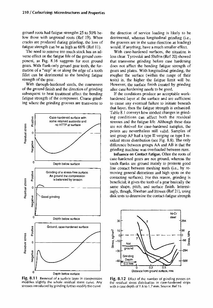
210/ Carburizing: Microstructures and Properties
588
98 Ifo :::E
u;-98 ~
294
-294
Ni-Crsteel
Not
ground
GrindingDepth
0.3mm
30
E 10
~ 0
g-10 -.-30
Fig. 8.12 Effect of the number of grinding passes onthe residual stress distribution in case-hardened stripswith a case depth of 1.6 to 1.7 mm. Source: Ref 16
the direction of service loading is likely to bedetrimental, whereas longitudinal grinding (i.e.,the grooves are in the same direction as loading)would, if anything, have a much smaller effect.
With case-hardened surfaces, the situation isless clear. Tyrovskii and Shifrin (Ref 20) showedthat transverse grinding before case hardeningdoes not affect the bending fatigue strength ofgears and plates. With longitudinal grinding, therougher the surface (within the range of theirtests) is, the higher the fatigue limit will be.However, the surface finish created by grindingafter case hardening needs to be good.
If the conditions produce an acceptable workhardened layer at the surface and are sufficientto cause any eventual failure to initiate beneaththat layer, then the fatigue strength is enhanced.Table 8.1 conveys how modest changes in grinding conditions can affect both the residualstresses and the fatigue life. Although these dataare not derived for case-hardened samples, thepoints are nevertheless still valid. Samples oftest group AF had a type II verging on type I residual stress distribution (see Fig. 8.8). The onlydifference between groups AA and AB is that thegrinding machine was overhauled between runs.
Influence on Contact Fatigue. Often the roots ofcase-hardened gears are not ground, whereas thetooth flanks are ground mainly to promote goodline contact between meshing teeth (i.e., by removing general distortions and high spots on thecontacting surfaces). For this reason, grinding isbeneficial; it gives the teeth of a gear basically thesame shape, pitch, and surface finish. Interestingly, though, Sheehan and Howes (Ref 21), usingdisk tests to determine the contact-fatigue strength
Case-hardenedsurface withsome retained austenite and
no HTTP at surface
o
0 Depth below surface
Ql Grinding of a stress-free surface,>.- As ground the compression'iii
'" 0 is balanced by tension'" n,~'iii r>.(ij 0:::>"0'iii
i' Good grindingQl Qla: >~C>QlZ
0 Depth below surface
Ql Ground, case-hardenedsurface~'iii
'" 0
'" o,e'iii(ij 0:::>"0'iiiQl Qla: >
~C>QlZ
Ql>.-'iii
'" 0
'" n,~'iii(ij 0:::>"0'iiiQla:
Depth below surface
Fig. 8.11 Removal of a surface layer in compressionmodifies slightly the whole residual stress curve. Anystressesintroduced by grinding further modify the curve
ground roots had fatigue strengths 25 to 50% below those with unground roots (Ref 19). Whencracks are produced during grinding, the loss offatigue strength can be as high as 66% (Ref 11).
The need to remove too much stock has an adverse effect on the fatigue life of the ground component, as Fig. 8.16 suggests for root groundgears. With flank-only ground gear teeth, the formation of a "step" in or along the edge of a toothfillet can be detrimental to the bending fatiguestrength of the gear.
With through-hardened steels, the coarsenessof the ground finish and the direction of grindingsubsequent to heat treatment affect the bendingfatigue strength of the component. Coarse grinding where the grinding grooves are transverse to

of case-hardened surfaces, show that irrespectiveof surface carbon content and quenching technique, an as-heat-treated surface is superior to aheat-treated and ground surface. Taking all factorsinto consideration, the difference probably occursbecause the unground surface supports a morestable oil film than the ground surface.
In a later work (Ref 22), Sheehan and Howesconcluded that contact fatigue is influenced bythe surface roughness of the two mating surfaces, the sign of the sliding action (positive ornegative), and the type of lubricant. When theroughness of the loading member with positiveslip approaches the oil film thickness (0.1 to 0.2urn), the load carrying capacity increases appreciably. Thus, polished surfaces are superior toground surfaces. With respect to lubricant type,the contact fatigue strength of ground surfaces isfavored by base oil, whereas the best results forpolished surfaces are obtained when an extremepressure lubricant is used.
Postcarburizing Mechanical Treatments /211
Nakanishi et al. (Ref 23), taking the onset ofgray staining (rnicropitting) as the failure criterion, determined that initial surface roughness hasan effect on surface durability (Fig. 8.17). Thetangential load for surface-hardened gear teethwith a surface roughness (Rmax) of -1 urn is aboutten times that of teeth where Rmax is -4 J.lID.
The presence of grinding burns might not havemuch effect in pure rolling contact situations, because the main stresses are subsurface. However,in slide/roll situations, the surface condition andthe surface hardness are important, so that grinding burns and the changes of hardness associatedwith them have an adverse effect.
Influence on Wear. The influence of theas-ground roughness on wear of surfaces in relative motion depends on whether the combinedroughness of the surfaces in contact exceed theoil film thickness. If the surfaces are kept apartby the lubricant, then essentially no wear cantake place, assuming an absence of debris pass-
•~.
Q r==:-.~. ~..... 0_ -..--
Vitrified bond CBN -Axialo Tangential
+200
o~:E -200W-;- -400(/)
~u; -600OJ::J
~ -800QlII:
-1000
-1200o 0.1 0.2 0.3 0.4 0.5 0.6 0.7 0.8
Distance from surface, mm
•I- ~ ........
1'--._ -,. 00
,I ....
'I' -~III
J:. t
Vitrified bond CBN • Axial I0 Used grinding wheel o Tangential•B
+200
o~:E -200~
-;- -400(/)
~u; -600OJ::J
~ -800QlII:
-1000
-1200o 0.1 0.2 0.3 0.4 0.5 0.6 0.7 0.8
Distance from surface, mm
Fig. 8.13 Influence of wheel condition on the residual stress distribution. Infeeds (rnrn) and feed rates (mrn/rev) forthe used wheel were less than those for the newly dressed wheel. ax, axial; tg, tangential
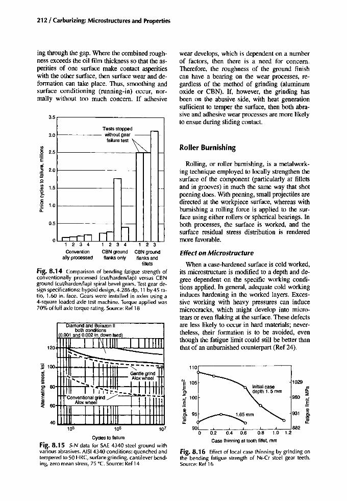
212/ Carburizing: Microstructures and Properties
Cyclesto failure
Fig. 8.15 $oN data for SAE 4340 steel ground withvarious abrasives. AISI 4340 conditions: quenched andtempered to 50 HRC, surface grinding, cantilever bending, zero mean stress, 75°C. Source: Ref 14
1029
8!.980
:::!E
~Qlr31 :::l
.~
If882
1.2l ! I I I
0.2 0.4 0.6 0.8 1.0
Casethinningat tooth fillet, mm
Fig. 8.16 Effect of local case thinning by grinding onthe bending fatigue strength of Ni-Cr steel gear teeth.Source: Ref 16
Effect on Microstructure
When a case-hardened surface is cold worked,its microstructure is modified to a depth and degree dependent on the specific working conditions applied. In general, adequate cold workinginduces hardening in the worked layers. Excessive working with heavy pressures can inducemicrocracks, which might develop into microtears or even flaking at the surface. These defectsare less likely to occur in hard materials; nevertheless, their formation is to be avoided, eventhough the fatigue limit could still be better thanthat of an unburnished counterpart (Ref 24).
E 105
~~ 100
~Ql
.~If
Rolling, or roller burnishing, is a metalworking technique employed to locally strengthen thesurface of the component (particularly at filletsand in grooves) in much the same way that shotpeening does. With peening, small projectiles aredirected at the workpiece surface, whereas withburnishing a rolling force is applied to the surface using either rollers or spherical bearings. Inboth processes, the surface is worked, and thesurface residual stress distribution is renderedmore favorable.
Roller Burnishing
wear develops, which is dependent on a numberof factors, then there is a need for concern.Therefore, the roughness of the ground finishcan have a bearing on the wear processes, regardless of the method of grinding (aluminumoxide or CBN). If, however, the grinding hasbeen on the abusive side, with heat generationsufficient to temper the surface, then both abrasive and adhesive wear processes are more likelyto ensue during sliding contact.
1 234
CBN groundflanks only
1 2 3 4
Conventionally processed
Tests stopped -withoutgear - -failure test~
-
I-
r--
- I-
- I-
- I-
, --n n lo
0.5
~ 2.5'E~.2 2.0!s~ 1.5
~c:.~ 1.0il:
3.5
~ 1OO++~I---1~I-t+t-tHIt--
iOl 8O++++tII-......,?:5~
~ 6O+++n":'=FrrrTTnT--+-4+++H+1
3.0
123
CBN groundflanks and
fillets
Fig. 8.14 Comparison of bending fatigue strength ofconventionally processed (cut/harden/lap) versus CBNground (cut/harden/lap) spiral bevel gears. Test gear design specifications: hypoid design, 4.286 dp, 11 by 45 ratio, 1.60 in. face. Gears were installed in axles using a4-square loaded axle test machine. Torque applied was70% of full axle torque rating. Source: Ref 18
ing through the gap. Where the combined roughness exceeds the oil film thickness so that the asperities of one surface make contact asperitieswith the other surface, then surface wear and deformation can take place. Thus, smoothing andsurface conditioning (running-in) occur, normally without too much concern. If adhesive

Postcarburizing Mechanical Treatments /213
Table 8.1 Effect on grinding conditions of residual stress and fatigue
Residual stressTest Wheel Downfeed Grinding Surface Peak Fatigue limit Failuregroup grade!a) mm 10-3 in. Duid MPa loJlb/in.2 MPa loJlb/in.2 MPa loJ Iblin.2 point
AA H 0.0025 0.1 Solubleoil 90 13 159 23 503 73 SurfaceAB H 0.0025 0.1 Soluble oil -172 -25 124 18 483 70 SurfaceBC I 0.Q25 1.0 Solubleoil 234 34 338 49 503 73 SurfaceAC M 0.05 2.0 Soluble oil -200 -29 841 122 427 62 SurfaceAF I 0.Q25 1.0 Grinding oil I -662 -96 7 I 683 99 SubsurfaceAG I 0.Q25 1.0 Grinding oil 2 -600 -87 145 21 627 91 SubsurfaceBA I 0.Q25 1.0 Grinding oil 2 (b) (b) (b) (b) 634 92 SubsurfaceAD M 0.Q25 1.0 Grinding oil I -462 -67 83 12 503 73 SurfaceAE M 0.05 2.0 Grinding oil I -738 -107 221 32 483 70 Surface
Steel:modified AISI 52100.59 HRC. Wheels: white. vitrified bond, friable aluminum oxide. (a) I, wheel gradenormally used;H, softer grade;M,hardergrade.(b) Comparablewith AG. Source:Ref 4
m=6,z,/z2=21/31, 0=20°, 1800 rpm, SAE30I-, I
o Carburizing and hardening _
0 l-:o Induction hardening
l-;;--.......
-0
'" 2.5c, '" '"C!l 2.0 n, Eo E~ 2.0
:;:,
~Ol
c£ -'"
1.5 c£ [ifl!! J:
'" l!! 1.5 --,.Q)
'" '"Ol Q) c£'0 OlQ) 1.0 '0C Q) 1.0
~Q) N
'E 'C::J
'" e Q)s: UC:: 0.5 '" co 0.5 !!!.2 Q,U ::J
'" '0::J '" c'0 o LUoS 0 0
0.4
0.3
0.2
0.1
oo 1.0 2.0 3.0 4.0 5.0 6.0
Initial surface roughness (Rmaxl, urn
Fig. 8.17 Effect of surface roughness on the surface durability of surface-hardened gears (PmaxlHB - Rmax curves).Source; Ref 23
Specific stress, kgf/mm2
Fig. 8.18 Influence of roller burnishing on the retained austenite content at and beneath the surface of acase-hardened steel. Source; Ref 27
Finely dispersed carbides have been observedwithin deformed austenite volumes, whichshould hinder slip along the slip planes. Razim(Ref 25), on the other hand, reasoned thatsimilar precipitates observed in the deformedcontact tracks of surface fatigue specimensare too large (probably incoherent) to hinderslip and, therefore, would not contribute to
Specific stress, MPa
1960 3920 5880
I~ 0.5 mm depth n n
<, 0
r-, 0
Surface u~ IU.l mm aeetr,
600400200
'#..,..~ 20t5::J
'"'0 10Q)c]jQ) 0a:
In deformed martensite-austenite structures,changes of orientation, slip line development inboth constituents (Ref 25), and a decrease in theaverage martensite plate size (Ref 26) have beenobservedas evidenceof the cold-working process.
At high rolling pressures, some of the austenite is transformed to martensite (Fig. 8.18), andthis transformation, in part, could account for thereduction of the average martensite plate size.Figure 8.18 shows that the change in the amountof retained austenite close to the surface (0.1mm) caused by high rolling pressures falls fromaround 20% down to about 5%. Papshev (Ref26) observed austenite reductions in a casehardened Ni-Cr-Mo steel from 30 to 13.5% andfrom 45 to 16% austenite. In tensile and bendtests, Krotine et al. (Ref 28) noted that strainingreduces austenite and increases the martensite atthe surfaces of carburized and hardened testpieces. There is an indication that the reductionof austenite content is greatest with higher nickelsteels (Table 8.2).
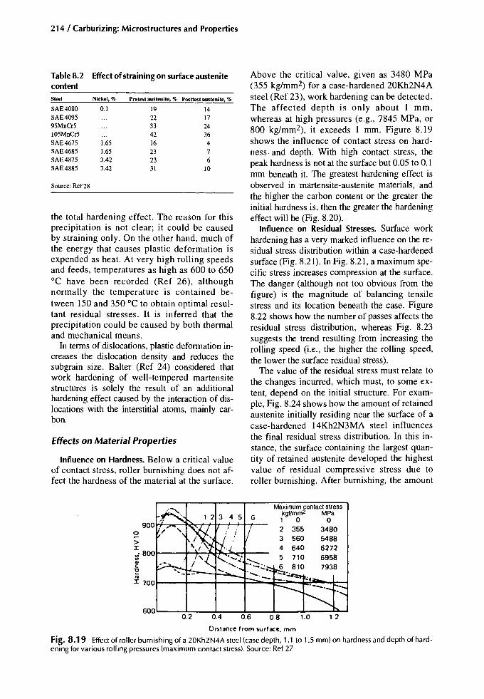
214/ Carburizing: Microstructures and Properties
Table8.2 Effect ofstraining on surface austenitecontentSteel Nickel, % Pretest austenite, % Posttest austenite, %
SAE4080 0.1 19 14SAE4095 22 1795MnCr5 33 24105MnCr5 42 36SAE4675 1.65 16 4SAE4685 1.65 23 7SAE4875 3.42 23 6SAE4885 3.42 31 10
Source: Ref 28
the total hardening effect. The reason for thisprecipitation is not clear; it could be causedby straining only. On the other hand, much ofthe energy that causes plastic deformation isexpended as heat. At very high rolling speedsand feeds, temperatures as high as 600 to 650°C have been recorded (Ref 26), althoughnormally the temperature is contained between 150 and 350°C to obtain optimal resultant residual stresses. It is inferred that theprecipitation could be caused by both thermaland mechanical means.
In terms of dislocations, plastic deformation increases the dislocation density and reduces thesubgrain size. Balter (Ref 24) considered thatwork hardening of well-tempered martensitestructures is solely the result of an additionalhardening effect caused by the interaction of dislocations with the interstitial atoms, mainly carbon.
Effects on Material Properties
Influence on Hardness. Below a critical valueof contact stress, roller burnishing does not affect the hardness of the material at the surface.
Above the critical value, given as 3480 MPa(355 kg/rnm-) for a case-hardened 20Kh2N4Asteel (Ref 23), work hardening can be detected.The affected depth is only about 1 mm,whereas at high pressures (e.g., 7845 MPa, or800 kg/mm-), it exceeds 1 mm. Figure 8.19shows the influence of contact stress on hardness. and depth. With high contact stress, thepeak hardness is not at the surface but 0.05 to 0.1mm beneath it. The greatest hardening effect isobserved in martensite-austenite materials, andthe higher the carbon content or the greater theinitial hardness is, then the greater the hardeningeffect will be (Fig. 8.20).
Influence on Residual Stresses. Surface workhardening has a very marked influence on the residual stress distribution within a case-hardenedsurface (Fig. 8.21). In Fig. 8.21, a maximum specific stress increases compression at the surface.The danger (although not too obvious from thefigure) is the magnitude of balancing tensilestress and its location beneath the case. Figure8.22 shows how the number of passes affects theresidual stress distribution, whereas Fig. 8.23suggests the trend resulting from increasing therolling speed (i.e., the higher the rolling speed,the lower the surface residual stress).
The value of the residual stress must relate tothe changes incurred, which must, to some extent, depend on the initial structure. For example, Fig. 8.24 shows how the amount of retainedaustenite initially residing near the surface of acase-hardened 14Kh2N3MA steel influencesthe final residual stress distribution. In this instance, the surface containing the largest quantity of retained austenite developed the highestvalue of residual compressive stress due toroller burnishing. After burnishing, the amount
1.21.0
Maximum contact stresskgf/mm2 MPa1 0 02 355 34803 560 54884 640 62725 710 69586 810 7938
0.80.60.40.2
>:x:"i 8001---+-*.~..e-...;:-.ood--'".,C"0i;
:x: 7001-----1I---+---+..;;:::o-oot::::~-+=:'~-t:::::__t
Distance from surface. mm
Fig. 8.19 Effect of roller burnishing of a 20Kh2N4A steel (case depth, 1.1 to 1.5 mm) on hardness and depth of hardening for various rolling pressures (maximum contact stress). Source: Ref 27

Postcarburizing Mechanical Treatments / 215
Initial hardness. HV
Fig. 8.20 Relationship between initial hardness andchange of hardnessdue to roller burnishing. Source:Ref26
80
800600
X ~arbon st~el !o Alloy steel
0 )
to~
11~V
o200 400
40
160
120
ill'"~uC
>::I:<l~.
QlC
"E'"s:c
of austenite surviving in each was only about15%.
Influence on Bending Fatigue. The bendingfatigue strength reaches a maximum at an intermediate value of roIling pressure (Fig. 8.25), increasing about 22% for the material burnishedwith optimal process conditions compared withthe unburnished one. Figure 8.25 represents results from unnotched test pieces, and it is conceivable that where stress concentrators exist(fiIlets, etc.), the improvement might even bebetter. This conjecture was correct with throughhardened test pieces (Ref 29), where the improvement was greater than 100%.
Influence on Contact Fatigue. In both laboratory and field tests (Ref 25), surface cold working improved the lives of case-hardened drill bitsand bearing race grooves by retarding the formation and the development of contact fatiguecracks.
0 0
'"E-490 E -50til :;:,
0.. Cl::E -"
iii iiiUl
Ul Q)
~ -980 ~ -1001ij(ij (ij
:J 'x'C til'iii
~ -150£-1470'C !'iii IQ) I Ic:: I I
-1960 -200, ,..'
-2450 -250
MaximumSpecimen specific stress
No, kgf/mm2 MPa
o 0365 3577445 4361560 5488645 6321710 6958765 7497810 7938
Fi~. 8.21 Distribution of residual axial stresses in the surface layer of carburized cylindrical specimens subjected toroller burnishing at various maximum specific stress levels. Source: Ref 27
o
-392
(ij:::J:gUlQ)
c::
(ij'xl1l
-784 ~ -80 IH--+---i'C'iiiQ)
-1177 c:: -120 '--_......._---'__----'"' .uL__......
Fi~. 8.22 Influence of number of passeswhen roller burnishing (with maximum specific stressof 4364 MPa, or 445kgtlmm2) on residual axial stresses in the surface layer of specimens. Source: Ref 27

216 / Carburizing: Microstructures and Properties
Influence on Wear. Roller burnished surfacesare more resistant to wear than in the as-groundcondition (Table 8.3).
20,----..,..----.--""'1196
0 ~:::;iii(/l
~iii
-196 ~::>..,'iiiQ)II:
f---+---1-....-392
o 1.0 2.0Distance from surface, mm
Fig. 8.23 Effect of rolling speed on the residual stressdistribution at the surface of a 0.45% C steel. Source:Ref26
Shot Peening
Shot peening is a process in which the component surface is bombarded with a multitude ofsmall spherical projectiles (shot) with sufficientvelocity to produce a minute indentation witheach impingement (a discrete zone of plastic deformation). The rate and duration of the bombardment need to be sufficient to saturate the entire surface of the target area with overlappingimpingements. The treated surface is evenly coldworked to a uniform but shallow depth, and thehardness and strength of the material in that layerare increased. The primary purpose of shotpeening, however, is to induce compressive residual stresses at the surface, which, among otherthings, improves the fatigue resistance. Shotpeening is a strength improvement process in itsown right, and it need only be applied to criticalareas where peak stresses are anticipated duringservice, such as in the radius at a change of section of a multidiameter shaft or at the tooth filletsof gears. Shot peening is not to be confused withthe overall cleaning process of shot blasting,which, although similar, does not have the samecontrol or the same objectives.
20,.....--......---'T""'--.196
Process Control
In order to obtain the maximum benefits fromshot peening, it is necessary to maintain a strict
10066675055
Burnishing pressureMP. kgf/mm 2
1472 1502256 2302747 2802943 300
Workpiececondition
Tests conducted on steel14Kh2N3MA, 57 to 61 HRC before and 3to 5units harder after burnishing. Testing condition: rolling friction in claysolution. Source: Ref 26
GroundGround and burnishedGround and burnishedGround and burnishedGround and burnished
Table8.3 Effect of burnishingon relative wear
Maximum contact stress, MPa
",EE 1960 3920 5880 g>~
IP I/~:H£.~81----__ ~784£Jj!Jj! 0 200 400 600 800
Maximum contact stress, kgf/mm 2
Fig. 8.25 Relationship between fatigue limit at 107 cycles and contact stress for case-hardened 20Kh2N4A testpieces (7.5 mm diam, 1.1 to 1.5 mm casedepth). Source:Ref 27
2.01.0
H---+----t--t-784
o
0
EEC. '"-196 ll.oX ~vi iii'" (/l
~ ~
'" iil~
-392(ij
::> ::>"0 "0,;; 'iii.. Q)
a: a:
-588
Distance from surface, mm
Fig. 8.24 An indication of how retained austenite content influences the residual stress distribution of acase-hardened and burnished Ni-Cr-Mo steel. Note: burnishing reduced the 30% austenite to 13.5% and the 45%austenite to 16%. Source: Ref 26

policy of good "housekeeping" and tight processcontrol. The type, hardness, size, shape, grading,and condition of the shot; its impact velocity andimpingement angle; exposure time; nozzle size;and nozzle to workpiece distance must be carefully controlled at all times to ensure optimal results and reproducibility.
Machine settings for peening a particularworkpiece are derived from peening standardtest pieces (Almen strips) and also from past experiences of how shot-peened parts have behaved under test or service conditions. Details ofthe test strips and their use can be obtained fromrelevant specifications, such as SAE J442 andJ443. Briefly, a set of test strips of appropriatethickness and hardness are attached to blocksand subjected to peening on one face for different exposure times. After peening and removalfrom the blocks, each strip deflects to a degreerelated to the induced residual stresses in thepeened face. These deflections (arc heights) arethen measured and plotted in terms of arc-heightagainst exposure time to produce a curve (Fig.8.26). From this information, the basis for thecorrect process settings can be derived.
A case-hardened surface is relatively resistantto indentation. When it is struck by a sphericalshot, the indented area is smaller than a comparable collision area on the surface of an Almenstrip (44 to 50 HRC). Therefore, for completesaturation of the surface with overlapping indentations, the exposure time for a case-hardenedpart is longer than for the Almen strip. It is important, nevertheless, not to overpeen to wheresmall surface ruptures are induced. Such a condition can be detrimental to the service life of acomponent. The unexpected presence of a soft
T 2T
Exposure time, T
Fig. 8.26 Typical saturation curve from shot-peenedAlmen strips. The time to saturation is that which, whendoubled, does not produce an increase of arc heightgreater than 20%.
Postcarburizing Mechanical Treatments /217
"skin" on a case-hardened surface (e.g., fromHTIP that may accompany internal oxidation)could encourage overpeening. In such an instance one might consider grit blasting first to remove some, if not all, of the soft layer followedby a controlled shot peening.
The shot used for case-hardened parts shouldhave equivalent, if not greater, hardness than thatof the surface being peened. Thus, the intendedincrease of compressive residual stresses and therequired consistency of peening will be achieved(Fig. 8.27). A softer shot might itself deform, assume an irregular shape, and thereby reduce theeffectiveness of the process. The size of the shotmust be considered in connection with the geometry of the surface to be peened. No improvement is obtained if, in the critical section of thecomponent, there is a radius smaller than that ofthe shot being used; the shot must have good access.
Effect on Microstructure
The microstructural features resulting fromshot peening mainly involve plastic deformationand are essentially the same as those described
+50'iii '"~ Eui 0 0 E'" 0,e ~
u; -50 -50 uim(ij Q)
::J ~'0 -100'iii -100 (ijQ) ::Ja: '0
-150 -150 'iiiRc61 shot Q)
a:
0.004 0.008 0.012(a) Depth,in,
0 '"E'iii
-50 ~~
ui -50 ~
'" ui~ '"u; Q)
(ij -100 ~::J (ij'0 ::J'iii Rc 61 shot -150 :>1Q)
'"a: Q)
a:-250
0 0.004 0.008 0.012
Depth, in.
(b)
Fig 8.27 Effect of shot hardness and surface hardnesson the distribution of residual stresses. (a) 1045 steelhardened to Rc 48. (b) 1045 steel hardened to Rc 62peened with 330 shot. Source: Ref 30
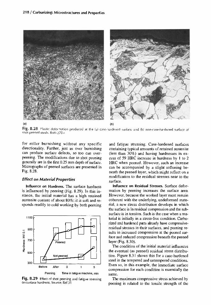
218 / Carburizing: Microstructures and Properties
w ~
Fig. 8.28 Plastic defor mat ion produced at the (a) ca se- hardened surface and (b) non- ease-harden ed surface ofsho t-peened stee ls. Both 270 x
Fig. 8.29 Effect of shot peening and fatigue stress ingon surface hardness. Source: Ref 31
for roll er burnishing without any specificdirectionality. Further, just as over burnishingcan produce surface defects, so too can overpeening. The modifications due to shot peeninggenerally are in the first 0.25 mm depth of surface.Micrographs of peened surfaces are presented inFig. 8.28.
Effect on Material Properties
Influence on Hardness. The surface hardnessis influenced by peening (Fig. 8.29). In this instance, the initial material has a high retainedaustenite content of about 80%; it is soft and responds readily to cold working by both peening
and fatigue stress ing. Case-hardened surfacescontaining typical amounts of retained austenite(less than 30%) and having hardnesses in excess of 59 HRC increase in hardness by I to 2HRC when peened. However, such an increasecan be accompanied by a slight softening beneath the peened layer, which might reflect on amodificat ion to the residual stresses near to thesurface.
Influence on Residual Stresses. Surface deformation by peening increases the surface area.However, because the worked layer must remaincoherent with the underlying, undeformed material, a new stress distribution develops in whichthe surface is in residual compression and the subsurface is in tension. Such is the case when a material is initialIy in a stress-free condition. Carburized and hardened parts already have compressiveresidual stresses in their surfaces, and peening results in increased compression at the peened surface and reduced compression beneath the peenedlayer (Fig. 8.30).
The condition of the initial material influencesthe eventual (as peened) residual stress distribution. Figure 8.31 shows this for a case-hardenedsteel in the tempered and untempered conditions.Even so, in this example, the immediate surfacecompression for each condition is essentialIy thesame.
The maximum compressive stress achieved bypeening is related to the tensile strength of the
5o
TIme in fatigue machine, minPeening
Before After
1100
900ci>J:vi 700IIIQlc'E'"J:
500Notpeened
300

Postcarburizing Mechanical Treatments /219
Peening intensity Mean 8·10Fatiguelife at a givenload,cycles
Table8.4 Effect of peening intensity on fatigueresistance
Test material: SAE 4023, carburized and quenched, 200°C temper,58 HRC. Peening: 110% saturation for 2 x 100% A1men saturation.Source: Ref 34
567,708
11,51211,9533,5682,663
9,85016,57123,80033,16724,75016,375
Unpeened12A18A24A8C24A (conventional)
a-- Depth of surfaceI layer affected by: shot peening
IIIII
-~---- ---------/( Retained austenite
/1I
MartensiteIII
t'">.,'w
'" 0'" n.~1iie~ 0Eiii
,3 ~".~ .u
a:: 5l'z,j.
Table8.5 Fatiguelimitsdetermined forcarburized steel specimens
Depth below surface -.
Fig. 8.30 Effect of shot peening on residual macrostress distributions in a carburized surface (initially withtensile residual stress at the surface). Source: Ref 32 Condition Fatigue limit, MPa
EN353 composition: 0.6 to 0.9 Mn, 0.8 to 1.2 Cr, 0.1 to 0.2 Mo, 1.2to1.7 Ni. EN16 composition: 0.32 to 0.4 C, 1.3 to 1.7 Mn, 0.22 to 0.32Mo. Source: Ref32
material, and it is typically 0.5 to 0.6 times theultimate tensile stress (Ref 30). The increase ofsurface and near-surface compressive residualstresses in a given steel is determined by the process parameters. For instance, Table 8.4 shows theeffect of peening intensity, including an exampleof slight overpeening, on both the residualstresses and the mean fatigue life (low cycle).Table 8.5 provides data relating to peening intensity and fatigue limit (high cycle). Figure8.27 shows the need to use hard shot for case-
EN353CarburizedlquenchedCarburizedlquenched + subzero treatmentCarburizedlquenched + 0.008A shot peenCarburizedlquenched + 0.D14Ashot peenCarburizedlquenched + 0.025A shot peen
EN16CarburizedlquenchedCarburizedlquenched + 0.008A shot peenCarburizedlquenched + 0.0 14A shot peenCarburizedlquenched + 0.025A shot peen
621542686718686
542605671608
'0osn.~
iii'"
-100 ~1iiiii::::J"C'w'"a::
-200
-300
r--: 100
2 3 4
-79 kglmm2
850 ·C quenchedShot peened
o2 3 4
-83 kg/mm2
850 ·C quenched180·C temperedShot peened
2 3 4 0
850 ·C quenched180 ·C tempered850 ·C quenched
o t-----jt----t
8('--
'"E -8~"'"iii'"~ -161iiiii::::J"C'w'" -24a::
-32
~-40
0 2 3 4 0
Distance from surface, mm
Fig. 8.31 Effectofshot peening on the residual stressdistribution in 20KhNM steel rings (casedepth, 1 rnrn). Source: Ref33

220 / Carburizing: Microstructures and Properties
hardened surfaces if the desired residual stressdistributions are to be achieved.
Influence on Fatigue. Whereas the axial fatigue strength of a part is unlikely to be improved by controlled shot peening, the bendingfatigue limit is improved (Fig. 8.32) about 20%(Ref 33, 36, 37). However, the current understanding of, equipment for, and refinement of theshot-peening process indicates that much higherquality products are possible, consistent with extremely good fatigue lives in the high-cycle regime. Low-cycle fatigue strength is not greatlyaffected by peening (Fig. 8.33).
The influence of peening intensity on fatigueresistance is presented in Table 8.4. The effectof peening duration is shown in Fig. 8.34,where the fatigue limit increases with peeningtime, although at greater times it levels off before diminishing when the point of overpeeningis reached.
Influence on Contact Fatigue. There are fewdata regarding the effect of peening on the contact fatigue resistance of case-hardened parts.Further, it is difficult to predict what effectpeening might have. For contact loading situations, the surface roughness plays an importantrole, and for surfaces roughened by peening,the asperities might penetrate the lubricatingoil film, thereby encouraging contact damage.By removing or reducing the roughness by polishing, for example, the real benefit of peeningcan be realized. Nevertheless, the presence ofcompression at the peened and polished sur-
face should inhibit failures that normally initiateat the immediate surface from sliding.
Gerasimova and Ryzhov (Ref 40), however,found no correlation between contact enduranceand residual stresses or hardness; improvement ismore influenced by subgrain size and dislocationstability. Tempering further improves the contactfatigue strength of peened parts, which is improvedyet again by electropolishing to remove 12 urn (toremove surface roughness). Altogether, the combined processes of peening, tempering, andelectropolishing raise the contact endurance byseveral hundred percent. A NASA study (Ref 41)concluded that the contact fatigue life is improved60% by shot peening, presumably by strengtheningthe surface against sliding damage. Overpeening,on the other hand, is expected to have a detrimentaleffect on contact- fatigue strength because it weakens the surface and encourages sliding damage.Shot peening has no beneficial influence on deepspalling fatigue processes.
Shot Peening for Reclamation. To some degree, shot peening might be employed as acorrective treatment. The presence of HTTPassociated with internal oxidation has alreadybeen mentioned. Other features, such as grinding damage or decarburization, which canrender a part unfit for service, are still potential candidates for peening. If the extent ofthe defect is known, then with the approvalof the design engineer, it may be possible tosalvage the defective item by shot peening.With respect to damage caused by abusive
100,-------,-------,-------,--------,
620 90Nickel-chromium molybdenum
steel carburized
'" 550 80 Shot peened,a. ~ then honed~
iii iii'"'" ie
Shot peenediii 485 70
Polished
Honed415 60
Surface as-carburized
345 50103 104 105 106 107
Cycles of reversed bending for fracture
Fig. 8.32 Effect of peening, honing, and polishing on the reversed bending fatigue strength of a carburized alloy steel.Source: Ref 35

Postcarburizing Mechanical Treatments / 221
grinding, Fig. 8.35 show that reclamation bypeening is possible. Figure 8.36, which considers decarburization, also suggests that, to apoint, reclamation might be possible.
Apart from reclamation work, peening can beapplied between the carburizing and the harden-
ing stages (while the case is relatively soft) toremove internal oxidation, to smooth out coarsemachining marks, and to effect some degree ofgrain refinement at the immediate surface.
The compressive stresses developed by goodgrinding or peening are of a similar magnitude,
Distance from surface, in.
o 0.002 0.004 0.006 0.008 o 0.002 0.004 0.006 0.008
o --- o
-100
~ -200~
gf -300~en
~ -400"0'en£ -500
--BOO ~
-700
-• Martensite
o Austenite
Unpeened
-20
-80
-100
o 0.05 0.10 0.15 0.20 0.25 o 0.05 0.10 0.15 0.20 0.25
(a) Distance from surface, mm
-Carburized SAE 4028
E:::>E'x'"~
730 1051035 150
FatigueendurancelimitMPa ksI
• 300
2240 3252265 329
MPa ksi
· 200
Peened ..Unpeened ~ 100
·. ., 0
106 107
Impactfracturestress
~9-'-----40.
~ 2000~
uien~inQl:::>Cl
~E 1000:::>E'x'"~
0 .103 104 105
Cycles
(b)
Surface Corehardness(a), hardness, Effective case deplh(b)
Steel Condition HRC HRC nun in.
Carburized Unpeened 60.5 35 1.1 0.044SAE4028 Shotpeened 62.2 36 1.1 0.044
(a) Converted from HRA. (h) Distanceto 510HV
Fig. 8.33 Influence of shot peening on (a) residual stresses within austenite and martensite of a case-hardened surfaceand (b) fatigue strength. Table shows influence of shot peening on impact fracture stress. Source: Ref 38

222 / Carburizing: Microstructures and Properties
Summary
Non-decarburized
4O~--+--+---F=---t10 ""- ....__--' .... ...
104 105 106
Cyclesto failure
Fig. 8.36 Effect of shot peening on decarburizationof 5AE 4340 steel (u Itimate tensi Ie strength, 280 ksi),kt = 1, R = -1, decarburization 0.003 in. to 0.03in.,shot peening with 0.28 in. diam shot, 0.12A density.Source: Ref 30
Decarburized
240----..-----.---.....---..,
200 ....\'r--,."lt---+---t----i
~enon~
iii 120I---~~-~d--.....::=::f=---i
160 ...--.....~~--+---+---...-t
80 ~---t""",,",~r+--
tion and growth control are important. Forgrinding, the wheel grade, wheel speed, anddepth of cut are important for a successful operation, and each must be selected with care.
• In-process considerations: Find the high spots,and proceed with light cuts. If wet grinding isdone, ensure that coolant feed is adequate andcorrectly directed. Dress the abrasive wheelearly; if operators wait until the sound ofgrinding changes, it may be too late for theworkpiece.
• Postprocess considerations: Inspect for grinding burns, grinding cracks, and grinding stepsin gear tooth fillets. Investigate reasons forany grinding damage. Corrective grinding ispossible in some instances, in which case theuse of a freshly dressed wheel should be considered. Tempering and peening are sometimesapplied to ground surfaces to further improvetheir quality.
• Effect on properties: Accuracy of contactwith static or moving surfaces is essential forgood load distribution. Ground surfaces varyfrom good quality (with compressive-residualstresses) to poor quality (with burns or evencracks). These quality levels determine whetherbending-fatigue strength is improved or seri-
~
~'"s 801-----rr7"'f------+------I784 5,
~ ~~ ~~ cc ~~ cc '"'" ~~
100r------r-----,-------, 980'EE~
120 84
100 70C\lE
"iii ~-'"<Ii 80 56 -'"en <Ii'" enfA ~
60 42 iii
40 28104 105 106 107 108
Cycles to failure
Fig. 8.35 Shot peening improves endurance limits ofground parts. Reversed bending fatigue of flat bars of 45HRC. Source: Ref 42
20 40Peening duration,s
Fig. 8.34 Effect of saturation time on the bending fatigue strength of pinion teeth (pack carburized to 1.1 mmcase depth). Source: Ref 39
but the depth of compression is greater afterpeening. Fig. 8.37 shows that with good grindingtechniques, there is little to choose between conventional (aluminum oxide) grinding and CBNgrinding, at lease not as far as the residualstresses go.
Grinding
Grinding removes adverse surface featurespresent after heat treatment (e.g., inaccuraciesdue to distortion and growth, surface roughness,internal oxidation). It is done primarily to provide accuracy and finish. The advantages ofgrinding can be lost if the grinding operation isnot well executed.
• Preprocess considerations: A properly designedcase-hardening process should provide surfacemicrostructures containing essentially fine, tempered martensite with a fair level of part-topart and batch-to-batch consistency. Distor-

Postcarburizing Mechanical Treatments / 223
-100o 0.005 0.010
Depth below surface, in.
o Shot-peened• As-ground
I- (conventional)-
III
.;~
+50
o
-100o 0.005 0.010
Depth below surface, in.
-25
c.~ -50en~
~ -75oo
c.~ +25c~
o Shot-peened• As-ground (CBN)
.,IfI
o
+50
-25
c.~ -50en~
~ -75oo
c.~ +25c~
(a) (b)
Fig. 8.37 Residual stresses in (a) CBN ground and (b) ground and shot peened surfaces for 9310 steel, 10 in. dp.Source: Ref 8
ously impaired. For contact fatigue, grindingimproves the accuracy of contact and provides surfaces smooth enough to be separatedby standard lubricating oils.
• Standards: Refer to magnetic-particle crackdetection standards for grinding cracks, forexample, ASTM E 1444-94a. Refer to temper-etch standards for grinding bums, for example, MIL-STD-867A.
Shot Peening
Shot peening is a surface treatment that increases skin hardness and induces compressivestresses into the immediate surface of theworkpiece. It can also remove directional machining marks, thereby providing a more randomfinish. The process can be confined by maskingto improve only the most critically stressed areas.
• Preprocess considerations: The benefits ofpeening are more assured if the initial surfaceis relatively smooth. Rough machined andragged surfaces may lead to folded-in defects.Prior to treating, the type of shot and the precise process parameters must be determined,for example, by Almen strip, to suit the material and the hardness of the workpiece. Checkshot condition; shot should be round.
• In-process considerations: Strict control ofprocess settings is essential.
• Postprocess considerations: Check for complete coverage of the peened area.
• Effect on properties: Under bending conditions, fatigue cracks generally initiate at thesurface. Metalworking by shot peening in-
duces compressive-residual stresses withinthe surfaces of treated parts, thereby reducingthe possibility of fatigue crack initiation at thesurface. A 20% improvement in fatigue limitor high-cycle fatigue life has been quoted.Improvements in contact-fatigue resistanceare also reported.
• Standards: ANSIIAGMA recommends thatgrade 2 gears be shot peened if the tooth rootsare ground. For grade 3 gears, it requires thattooth roots and fillets are shot peened. Guidelines for shot peening gears are provided inAGMA 2004-BXX 1/88.
REFERENCES
Grinding
1. H. Grisbrook, H. Moran, and D. Shepherd,Metal Removal by a Single Abrasive Grit,Machinability, Special report 94, The Iron andSteel Institute, 1967, p 25-29
2. A.A. Mikhailov, The Origin of GrindingCracks, Russ. Eng. J., Vol XLVIII (No.9),1968, p 73-76
3. E. Schreiber, Residual Stress Formation duringGrinding Hardened Steels, Hart-Tech. Mitt.(BISI 13783), Vol 28 (No.3), 1973, p 186-200
4. L.P. Tarasov, W.S. Hyler, and H.R. Letner,Effect of Grinding Conditions and ResultantResidual Stresses on the Fatigue Strength ofHardened Steel, Proc. ASTM, Vol 57, 1957,P 601-622
5. K.K. Bumakov et aI., Reasons for Crack Formation in Grinding, Russ. Eng. J., Vol LV (No.9), 1975, P 52-54

224 / Carburizing: Microstructures and Properties
6. M.W. Gormly, Residual Grinding Stresses,Grinding Stresses-Cause, Effect and Control,Grinding Wheel Institute, p 7-21
7. lE. Price, Improving Reliability of GroundParts by Avoiding Residual Stress, GrindingStresses-Cause, Effect and Control, GrindingWheel Institute, p 27-30
8. J.R. Drago, Comparative Load Capacity Evaluation ofCBN-Finished Gears, Gear Technol.,May/June 1990, p 8-16, 48
9. D.V. Kumar, "Technological Fundamentals ofCBN Bevel Gear Finish Grinding," SAE paperMR85-273, SAE Conf. on Superabrasives(Chicago), Society of Automotive Engineers,1985
10. K. Neailey, Surface Integrity of MachinedComponents-Microstructural Aspects, Met.Mater., Feb 1988, p 93-96
11. H. Staudinger, Bending Fatigue Strength ofCarburised and Nitrided Steels ContainingGrinding Cracks, Z. VD!, Vol 88, 1944, P681--ti86
12.AV. Podzei and AV. Yakimov, Grinding Defects and Their Remedy, Russ. Eng. J., Vol LIT(No.3), 1972, P 66--ti8
13.lE. Vamai, Effect of Tempering on GrindingCracks in Case-Hardening Parts, HeatTreating '76, Proc. 16th Int. Heat TreatmentConf. (Stratford, UK), Metals Society, 1976, p95-98
14.N.P. Navarro, "The Technical and EconomicAspects of Grinding Steel with Borazon TypeIT and Diamond," SME paper MR70-198, Society of Manufacturing Engineers, April 1970
15. AL. Ball, Controlling Grinding Stresses,Grinding Stresses-Cause, Effect and Control,Grinding Wheel Institute, p 63--ti7
16. V.S. Sagaradze and L.V. Malygina, The Fatigue Strength of Carburized Steel afterGrinding, Met. Sci. Heat Treat., Vol 12/13,Dec 1971, p 1050--1052
17. W. Konig, G. Mauer, and G. Rober, CBN GearGrinding-A Way to Higher Load Capacity?,Gear Technol., NovlDec 1993, p 10--16
18. G.I. Kimmet and H.D. Dodd, "CBN FinishGrinding of Hardened Spiral, Bevel, andHypoid Gears," AGMA Fall Technical Meeting, American Gear Manufacturers Association, Oct 1984
19. R.I. Love, "Bending Fatigue Strength of Carburised Gears," MIRA report No. 1953/4, Motor Industry Research Association, 1953
20. M.L. Tyrovskii and LM. Shifrin, Stress Concentration in the Surface Layer of Carburized
Steel, Russ. Eng. J., Vol L (No. Ill), 1970,P 47-50
21. lP. Sheehan and M.A.H. Howes, "The Effectof Case Carbon Content and Heat Treatmenton the Pitting Fatigue of 8620 Steel," SAE paper 720268, Society of Automotive Engineers,1972
22. lP. Sheehan and M.A.H. Howes, "The Role ofSurface Finish in Pitting Fatigue ofCarburizedSteel," SAE paper 730580, Society of Automotive Engineers, 1973
23. T. Nakanishi, Y. Ariura, and T. Ueno, LoadCarrying Capacity of Surface-Hardened Gears(Influence of Surface Roughness on SurfaceDurability), JSME Int. 1., Vol 30 (No. 259),1987, P 161-167
Roller Burnishing
24. M.A Balter, Effect of the Structure on the Fatigue Limit of Steel after Surface Hardening,Met. Sci. Heat Treat., Vol 13 (No.3), March1971, p 225-227
25. C. Razim, "Effects of Residual Austenite andRecticular Carbides on the Tendency to Pittingof Case-Hardened Steels," thesis, Techn.Hoschscule Stuttgart, 1967
26. D.D. Papshev, Increasing the Fatigue Strengthof High-Tensile Steels by Work-Hardening,Russ. Eng. J., Vol L (No.1), 1970, P 38-42
27. M.A Balter et aI., Roller Burnishing ofCarburized Steels, Russ. Eng. J., Vol XLIX (No.9),1969, p 69-72
28. F.T. Krotine, M.F. McGuire, i.r. Ebert, andAR. Troiano, The Influence of Case Properties and Retained Austenite on the Behaviourof Carburized Components, Trans. ASM, Vol62, 1969, P 829-838
29. LV. Kudryavtsev and N.M. Savvina, The Effect of Ten Years Holding on the FatigueStrength of Parts with Residual Stresses,Met Sci. Heat Treat., (No.4), April 1964,p 225-226
Shot Peening
30. M. Lawerenz and L Ekis, Optimum ShotPeening Specification I, Gear Technol.,NovlDec 1991, p 15-22
31. C. Razim, Influence of Residual Austenite onthe Strength Properties of Case-Hardened TestPieces during Fatiguing, Hart-Tech. Mitt.(BISI 6448), Vol 23, April 1968, P 1-8
32. D. Kirk, The Role of Residual Stress Measurement in Improving Heat Treatment, HeatTreat. Met., (No.3), 1985, p 77-80
33. D.A. Sveshnikov, LV. Kudryavtsev, N.A.Gulyaeva, and L.D. Golubovskaya, Chemicothermal Treatment of Gears, Met. Sci. HeatTreat., (No.7), July 1966, P 527-532
34. R.P. Garibay and N.S. Chang, Improved Fatigue Life of a Carburised Gear by ShotPeening Parameter Optimization, Proc. Processing and Performance (Lakewood, CO),ASM International, 1989, p 283-289
35. H.F. Moore, Strengthening Metal Parts byShot Peening, Iron Age, 28 Nov 1946, p 70-76
36.J.B. Seabrook and D.W. Dudley, Resultsof a Fifteen Year Program of Flexural Fatigue Testing of Gear Teeth, Trans. ASME,Series B, J. Eng. Industry, Vol 86, Aug1964, p 221-239
37. G.L Solod et al., Improving Bending Fatigueof Large-Module Gear Teeth, Russ. Eng. J.,Vol LIT (No.1), 1972, P 19-22
Postcarburizing MechanicalTreatments / 225
38. C. Kim, DE Diesburg, and R.M. Buck, Influence of Sub-Zero and Shot Peening Treatmentson Impact and Fracture Properties of CaseHardenedSteels,J. Heat Treat; Vol 12 (No.1),June 1981,p 43-53
39. M.L. Turovskii, Residual Stresses in the Clearance Curve of Case-Hardened Pinions, Russ.Eng. J., Vol LI (No.9), 1971, p 46-49
40. N.G. Gerasimova and N.M Ryzhov, Effect ofShot Peening on the Contact Endurance ofCase-Hardened Steel, Russ. Eng. 1., Vol 58(No.6), 1978, p 26-30
41. D.P. Townsend and E.V. Zaretsky, "Effect ofShot Peening on Surface Fatigue Life of Carburised and Hardened AISI 9310 Spur Gears,"NASA paper 2047, Aug 1982
42. M. Lawerenz and L Ekis, Optimum ShotPeening Specification II, Gear Technol.,JanlFeb 1992, p 30-33
Index
A
Abrasive weardecarburization influence . . . . . . . . . . . . . . . . . . . 47grinding influence. . . . . . . . . . . . . . . . . . . . . . . . . 212and internal oxidation . . . . . . . . . . . . . . . . 29–30(F)refrigeration influence . . . . . . . . . . . . . . . . 193–194retained austenite influence . . . . . . . . . . . . . . . . . 89tempering influence . . . . . . . . . . . . . . . . . . . . . . . 183
Ac temperature . . . . . . . . . . . . . . . . . . . . . . . . . 201(F)Accm temperature . . . . . . . . 53, 54(F), 56, 66, 67(F)
austenite stability . . . . . . . . . . . . . . . . . . . . . . . . . . 77quenching and microcracking . . . . . . . . . . 112, 113
Ac1 temperature . . . . . . . . . . . . . . . . . . . 53, 54(F), 69Ac3 temperature . . . . . . . . . . . . . . . . . . . . . . 54(F), 69
austenite stability . . . . . . . . . . . . . . . . . . . . . . . . . . 77heat treatments above, effect on
coarsening temperature. . . . . . . . . . . . . . . . 101Adhesive wear
decarburization influence . . . . . . . . . . . . . . . . . . . 47grinding influence. . . . . . . . . . . . . . . . . . . . . . . . . 212and internal oxidation . . . . . . . . . . . . . . . . 29–30(F)refrigeration influence . . . . . . . . . . . . . . . . 193–194retained austenite influence 89–90, 91, 92, 93, 94tempering influence . . . . . . . . . . . . . . . . . . . . . . . 183
Aerospace gear steels . . . . . . . . . . . . . . . . . . . . . . . . . 5Aging . . . . . . . . . . . . . . . . . . . . . . . . . . . . . . . . . 174, 208
room temperature . . . . . . . . . . . . . . . . . . . . . . . . . . 78tempering influence . . . . . . . . . . . . . . 184–185(F,T)
AGMA yield number . . . . . . . . . . . . . . . . . . . . . . . 142Air tempering . . . . . . . . . . . . . . . . . . . . . . . . . . . 184(T)Almen strips . . . . . . . . . . . . . . . . . . . . . . . . 217(F), 223Alumina . . . . . . . . . . . . . . . . . . . . . . . 123, 124(F), 125
effect on machinability of steels . . . . . . . . . . . . 128Alumina carbonitrides, as nonmetallic
inclusions. . . . . . . . . . . . . . . . . . . . . . . 125, 126(F)Aluminum
addition for grain refinement byalloying . . . . . . . . . . . . . . . . . . . . . . 100(F), 101
content effect with internal oxidation . . . . . . . . . 16oxidation potential . . . . . . . . . . . . . . . . . . . 11–12(F)with titanium, grain coarsening
temperature affected . . . . . . . . . . . . . . . . . . 100Aluminum nitride, as grain refining agent . . . . . 100Aluminum oxide
as grit material . . . . . . . . . . . . . . . . . 205(F), 209(F),212, 222, 223(F)
hardness, as nonmetallic inclusion . . . . . . . 121(T)
as nonmetallic inclusion . . . . . . . . . 120(T), 128(T)
Aluminum treated steels, grain size. . . . . . 100–101
Ammonia, to restore hardenability andstrength, in carburizing chamber . . . . . . . . . . . 32
Anisotropy effect. . . . . . . . . . . 120, 121(T), 122, 125
Apparent eutectoid . . . . . . . . . . . . . . . . . . . . . . . . . . . 9
Apparent eutectoid carbon . . . . . . . . . . . . . . . . . . . 56
Applications, high-temperature service . . . . . . . 135
Applied cyclic stresses . . . . . . . . . . . . . . . . . . . . . . . 86
Applied stresses . . . . . . . . . . . . . . . . . . . . . . . . . . . . . . 1
and case depth . . . . . . . . . . . . . . . . . . . . . . . . . . . . 163
and cycles in fatigue life stages . . . . . . . . . . . . . 161
and effective case depth . . . . . . . . . . . . 158(F), 159
Arsenic, segregation susceptibility. . . . . 114, 116(T)
Atmospheres
effect of decarburization . . . . . . . . . . . . . . 39, 40(T)
endothermic . . . . . . . . . . . . . . . . . . . . . . . . . 11–12(F)
exothermic-based . . . . . . . . . . . . . . . . . . . . . . . . . . 32
nitrogen-base . . . . . . . . . . . . . . . . . . . . . . . . . . . . . . 32
oxygen-free gas-carburizing . . . . . . . . . . . . . . . . . 11
Austenite
case hardenability . . . . . . . . . . . . . . . . . . . . 149–150
case transformation . . . . . . . . . . . . . . . . . . . . . . . 159
grinding defects. . . . . . . . . . . . . . . . . . . . . . . . . . . 207
grinding of. . . . . . . . . . . . . . . . . . . . . . . . . . . 200, 202
in case-hardened surface with contactdamage . . . . . . . . . . . . . . . . . . . . . . . . . . . . . . 155
internal oxidation and wear resistance . . . . . 29–30
surface carbon content . . . . . . . . . . . . . . . . 54–55(F)
tempering effect . . . . . . . . . . . . . . 173–174(T), 177,179–180, 181, 183
thermally stabilized . . . . . . . . . . . . . . . . . . . . . . . . 77
transformed by refrigeration . . . . . . . . 186, 187(F),188(T), 190–191,
192, 193–194untransformed, volume of . . . . . . . . . . . . . . . . . . . 79
Austenite formers . . . . . . . . . . . . . . . . . . . . . . . . 51–52
Austenite grain size . . . . . . . . . . . . . . . . . . . . . 81, 102
Austenitic stainless steels, heat-treatmentdeformations after quenching. . . . . . . . . . 166(F)
Austenitizing . . . . . . . . . . . . . . . . . . . 100–101(F), 165
Austenitizing temperature . . . . . . 66, 67(F), 201(F)
effect on microcrack sensitivity . . . . . . . . . . 109(F)
equilibrium conditions . . . . . . . . . . . . . . . . . . . . . . 53
Autotempering . . . . . . . . . . . . . . 172, 173(T), 175(F)

B
Bainite . . . . . . . . . . . . . . . . . . . . . . . . . . . . . . . . . . 55–56
after decarburization . . . . . . . . . . . . . . . . . . . . . 43(F)
case hardenability . . . . . . . . . . . . . . . . . . . . 149–150
case transformation . . . . . . . . . . . . . . . . . . . . . . . 157
of core . . . . . . . . . . . . . . . . . . . . . . . . . . . . . . . . . . . 145
and decarburization . . . . . . . . . . . . . . . . . . . . . . . . 57
and decarburization after internal oxidation . . . 24
in case-hardened surface with contactdamage . . . . . . . . . . . . . . . . . . . . . . . . . . . . . . 155
in cores during tempering . . . . . . . . . . . . . . . . . . 172
in cores of case-hardened parts. . 136, 137(F), 138
internal oxidation and wear resistance . . . . . . . . 30
lower. . . . . . . . . . . . . . . . . . . . . . . . . . . . . 173(T), 174
tempering effect . . . . . . . . . . . . . . . . . . 173(T), 174,
175, 178–179, 180upper . . . . . . . . . . . . . . . . . . . . . . . . . . . . . 173(T), 174
Balanced composition . . . . . . . . . . . . . . . . . . . . . . . 51
Ball bearings, contact fatigue andnonmetallic inclusions . . . . . . . . . . . . . . . . 127(F)
Bar end, carburized, microsegregation 116, 117(F)
Bearing fatigue tests . . . . . . . . . . . . . . . . . . . . . . . . 128
Bearing steels. See also Steels, SAE,specific types, 52100.
nonmetallic inclusions
effect on fatigue fractures . . . . . . . . . . . . . 125(F)
stress-raising properties. . . . . . . . . . . . . . . 124(F)
Bending, internal oxidation influence on 28–29(F)
Bending fatigue limit . . . . . . . . . . . . . . . . . . . . 84, 154
surface microhardness effect . . . . . . . . . . 25, 27(F)
Bending fatigue strength . . . . . . . . . . . . . . . . . . . . 1, 2
carbide influence . . . . . . 63–66(F,T), 67(F), 71–72
case carbon effect . . . . . . . . . . . . . . . . . . . . . . . . . 155
case depth influence . . . . . . . . . . . . . . . . . . . . . . . 167
decarburization influence . . . . . . . 45–46(F), 47(T)
effective case depth influence. . . . . 159–163(F,T),
164(F)grain size effect . . . . . . . . . . . . 106(F), 107, 108(T)
grinding influence . . . . . 208–210, 212(F), 213(T)
microsegregation influence . . . . . . . . . . . . . . 118(F)
nonmetallic inclusions influence . . . . 120, 121(T)
refrigeration influence . . . . . . . . . . . . . . . . . . . . . 193
retained austenite influence . . 89(F), 90(F), 91(F)
roller burnishing influence . . . . . . . . . . 215, 216(F)
rotating, overheating effect. . . . . . . . . . . . . . . . . 129
shot peening influence . . . . . . . . . . 219(T), 220(F),
221(F), 222(F)tempering influence . . . . . . . . . . . . . . 178–181(F,T)
vacuum carburizing effect . . . . . . . . . . . . . . . . 29(F)
Bending stress limits, for gears . . . . . . . . . . . . . . 4(T)
Bend testing . . . . . . . . . . . . . . . . . . . . . . 89, 90(F), 213
internal oxidation effect . . . . . . . . . . . . . . . . . . 29(F)
Boost-diffuse method of carburizing . . . . . . 151(F)
Boron, as grain refining agent . . . . . . . . . . . . . . . . 101
Bowden-Leben machine . . . . . . . . . . . . . . . 91, 92(F)
“Butterfly” inclusions . . . . . . . . . . . . 127(F), 128(T)
C
Calcium aluminates . . . . . . . . . . . . 120, 123, 124(F)as nonmetallic inclusions. . . . . . . 125, 126–127(F)
Calcium oxide . . . . . . . . . . . . . . . . . . . . . . . . . . . 124(F)Calcium sulfide. . . . . . . . . . . . . . . . . . . . . . . . . . 124(F)Calcium treatments . . . . . . . . . . . . . . . . . . . . . . . . 128
for decreasing number of nonmetallicinclusions. . . . . . . . . . . . . . . . . . . . . . . . . . . . 121
Carbide films, removed by grinding . . . . . . . . . . 199Carbide formers . . . . . . . . . . . . . . . . . . . . . . . . . 51–52
as alloying elements . . . . . . . . . . . . . . . . . . 109–110defined. . . . . . . . . . . . . . . . . . . . . . . . . . . . . . . . . . . . 51
Carbide network . . . . . . . . . . . . . . . . . . . . . . . . . . 4, 57Carbide precipitation . . . . . . . . . . . . . . . . . . 104, 183
and case hardenability . . . . . . . . . . . . . . . . . . . . . 150Carbides . . . . . . . . . . . . . . . . . . . . . . . . . . . . 51–73(F,T)
bending fatigue strength influence . . 63(T), 71–72bending fatigue strength
influenced by . . . . . . . . . . . . . 63–66(F), 67(F)of case-hardened surface . . . . . . . . . . . . . . . . . . . 200chemical composition . . . . . . . . . . . . . . 51–53(F,T)contact fatigue influenced by. . . . . . . 66–67(F), 72corner buildup . . . . . . . . . . . . . . . . . . . . . . . . . . . . . 55corner, heat treatment effect on
bending fatigue strength . . . . . . . . . . 64, 65(F)crack propagation . . . . . . . . . . . . . . . . . . . . 65, 66(F)critical crack size influenced by . . . . . . . . . . . 68(T)cyclic tensile stressing . . . . . . . . . . . . . . . . . . . . . . 65discontinuous . . . . . . . . . . . . . . . . . . . . . . . . . . . . . . 73dispersed . . . . . . . . . . . . . . . . . . . . . . . . 53–60(F), 73
effect on properties. . . . . . . . . . . . . . . 62–68(F,T)equilibrium . . . . . . . . . . . . . . . . . . . . . . . . . . . . . 52(T)equilibrium conditions . . . . . . . . . . . . . . . . . . . 53(F)fatigue life affected by . . . . . . . . . . . . . . . . . . . 63(T)film. . . . . . . . . . . . . . . . . . . . . . . . . . . . . . 70(F), 71(T)
effect on properties . . . . . . . . . . . . . . . . . . . 70–71formation of . . . . . . . . . . 56(F), 57(F), 61, 62(F)HTTP formation and . . . . . . . . . . . . . . . . . . . . . 72internal oxidation . . . . . . . . . . . . . . . . . . . . . . . . 72
flake . . . . . . . . . . . . . . . . . . . . . . . . . . . . . 70(F), 71(T)formation of. . . . . . . . . . . . . . . . . . . . . . 55(F), 56(F),
57(F), 60–61, 62(F)forming elements . . . . . . . . . . . . . . . . . . . . . . . 69–70forms . . . . . . . . . . . . . . . . . . . . . . . . . . . . . . . . . . . . . 51fracture strength affected by . . . . . . . . . . . . . . 63(T)fracture toughness influenced by . . . . . . . . 68(F,T)free . . . . . . . . . . . . . . . . . . . . . . . . . . . . . . 1, 54, 56, 73
case depth increases and . . . . . . . . . . . . . . . . . 158defined . . . . . . . . . . . . . . . . . . . . . . . . . . . . . . . . . 51white etching constituent . . . . . . . . . . . . . . . . . 81
geometric models formed duringcase-hardening . . . . . . . . . . . . . . . . . . . . . 62(F)
globular . . . . . . . . . . . . . . . . . . . . . . . . . . . . . . . 54, 62carbide influence on contact fatigue . . . . . . . . 72deposits . . . . . . . . . . . . . . . . . . . . . . . . . . 69–70(F)effect on properties . . . . . . . . . . . . . . . . . . . 70–71heavy dispersions and . . . . . . . . . . . . . . 69–70(F)
grain-boundary . . . . . . . . . . . . . . . . . . 54, 62, 65, 67grinding defects and . . . . . . . . . . . . . . . . . . . . . . . 207
228 / Index
hardness influenced by. . . . . . . . . . . . . . . . . . . . . . 71intragranular . . . . . . . . . . . . . . . . . . . . . . . . 61, 62(F)load carrying capability influenced by . . . . . 68(T)massive . . . . . . . . . . . . . . . . . . . . . . 53–60(F), 65, 73massive, formation of . . . . . . . . . . 55(F), 61, 62(F)massive, heat treatment effect. . . . . . . . . . . . . 65(F)near-equilibrium . . . . . . . . . . . . . . . . . . . . . . . . . . . 52network . . . . . . . . . . . 53–60(F), 65, 67–68, 73, 207
effect on properties. . . . . . . . . . . . . . . 62–68(F,T)heat treatment effect . . . . . . . . . . . . . . . . . . . 65(F)heat treatment effect on bending
fatigue . . . . . . . . . . . . . . . . . . . . . . . . . 64, 65(F)impact damage and. . . . . . . . . . . . . . . . . . . . . . . 68influence on contact fatigue . . . . . . . . . 66(F), 72metallographic examination . . . . . . 102, 103(F)
network/spheroidal heat treatment effect . . . 65(F)nonequilibrium cooling . . . . . . . . . . . . . . . 54–60(F)residual stresses influenced by . . . . . . . . 63(T), 65,
66(F), 71(F), 72(F)spheroidal . . . . . . . . . . . . . . . . . . . . . . . 52, 62, 63, 65
influence on contact fatigue . . . . . . . . . 66(F), 72spheroidized . . . . . . . . . . . . . . . . . . . . . . . . . . . 63, 67standards . . . . . . . . . . . . . . . . . . . . . . . . . . . . . . . . . . 73toughness influenced by . . . . . . . . . . . 63(T), 72–73wear influenced by . . . . . . . . . . . . . . . . . . . . . . . . . 73with decarburization. . . . . . . . . . . . . . . . . . . . . . . . 41
Carbide segregation . . . . . . . . . . . . . . . . . . . 177–178Carbon
as austenite former . . . . . . . . . . . . . . . . . . . . . . . . . 52content effect on fracture toughness . . . . 89, 91(F)content effect with internal oxidation. . . . . . 30–31effect on hardness after internal oxidation . . 24(F)released by gas-metal reactions . . . . . . . . . . . . . . 13
Carbon case hardening . . . . . . . . . . . . . . . . . . . . . . . 2drawbacks . . . . . . . . . . . . . . . . . . . . . . . . . . . . . . . . . . 2
Carbon-chromium steels, fatigue resistance 86(F)Carbon clustering . . . . . . . . . . . . . . . . . . . . . . . . . . 183Carbon dioxide, providing oxygen for
internal oxidation . . . . . . . . . . . . . . . . . . . . . . . . 11Carbon gradient . . . . . . . . . . . . . . . . . . . . 151(F), 156
negative, promoted by decarburization . . . . . . . 37positive, promoted by carburization . . . . . . . . . . 37with decarburization. . . . . . . . . . . . . . . . . . 41, 42(F)
Carbon-manganese-boron alloys
internal oxidation . . . . . . . . . . . . . . . . . . . . . . . 16–17Carbon monoxide, content effect on internal
oxidation of manganese chromium steels . . . 15Carbon-nickel-chromium steels
microstructures after cooling . . . . . . . . 136, 137(F)Carbon potential. . . . . . . . . . . . . . . . . . . . . . . . 32, 156
decarburization and . . . . . . . . . 38, 39(F),40–41(F)during carburizing . . . . . . . . . . . . . . . . . . . . . . . 38(F)of endothermic gas as function of
temperature . . . . . . . . . . . . . . . . . . . . . . . . 69(F)in film carbides . . . . . . . . . . . . . . . . . . . . . . . . . 70(F)in internal oxidation . . . . . . . . . . . . . . . . . . . . . . . . 18residual stress influenced by . . . . . . . . 158, 159(F)
Carbon segregation. . . . . . . . . . . . . 104, 172, 173(T)Carbon steels
grain size and normalizing effect 104–105, 106(F)
grain size influence on impactstrength . . . . . . . . . . . . . . . . . . . . . . 106(F), 107
impact strength influenced bygrain size. . . . . . . . . . . . . . . . . . . . . 107, 108(T)
nitriding. . . . . . . . . . . . . . . . . . . . . . . . . . . . . . . . . . . . 2Carburizing
cycle . . . . . . . . . . . . . . . . . . . . . . . . . . . . . . . . . . . 38(F)duration, and case depth . . . . . . . . . . . . . . . . . . . 156microstructural features . . . . . . . . . . . . . . . . . . . . . . 1variables . . . . . . . . . . . . . . . . . . . . . . . . . . . . . . . . . . . 1
Carburizing steels
chemical compositions. . . . . . . . . . . . . . . . . . 136(F)heat treatment deformations after
quenching. . . . . . . . . . . . . . . . . . . . . . . . . 166(F)strength vs. section diameter. . . . . . . . . . . . . 136(F)
Case carbon. . . . . . . . . . . . . . . . . . . . . . . . . . . . . . . . 168standards. . . . . . . . . . . . . . . . . . . . . . . . . . . . . . . . . 168
Case crushing. . . . . . . . . . . . . . . . . . . . . . . 148(F), 159contact damage influenced by case depth 162(T)
Case-crushing resistance . . . . . . . . . . . . . . . . . . . 162Case depth . . . . . . . . . . . . . . . . . . . . . . . . . . . . 167–168
bending fatigue influenced by. . . . . 159–163(F,T),164(F)
carbon content . . . . . . . . . . . . . . . . . . . . . . . . . . . . 168contact damage influenced by . . . . . . 162–163(F),
164(F)and core properties . . . . . . . . . . . . . . . 135–168(F,T)dependence on shape and size . . . . . . . 156–158(F)effect on internal oxidation . . . . . . . . . . . . . . . . . . 14and mechanical properties . . . . . . . . . . . . . . . 158(F)and residual stresses . . . . . . . . 158–159(F), 160(F)specifications . . . . . . . . . . . . . . . . . . . . . 6(F), 7–8(F)standards . . . . . . . . . . . . . . . . . . . . . . . . . . . . 167–168
Case depth-to-section thicknessratio (CD/t) . . . . . . . . . . . . . . . . 159–160, 161(F)
Case depth-to-tooth diametricalpitch relationship . . . . . . . . . . . . . . . . . . . . . 8(F)
Case factors . . . . . . . . . . . . . . . 148–163(F,T), 164(F)carbon content . . . . . . . . . . . 150–155(F,T), 156(F)carbon effect on
bending fatigue . . . . . . . . . . . . . . . . . . . . . . . . . 155case toughness . . . . . . . . . . . . . . . . 152–153(F,T)contact damage. . . . . . . . . . . . . . . . . . 155, 156(F)impact fatigue. . . . . . . . . . . . . . . . . . . 153–154(F)residual stresses . . . . . . . . . . . . . . . . . 154–155(T)surface hardness. . . . . . . . . . . . . . . . . 151–152(F)
effective case depth . . . . . . . . . . . . . . 155–161(F,T)hardenability. . . . . . . . . . . . . . . 138(F), 149–150(F)
Case hardenability. . . . . . . . . . . 138(F), 149–150(F)level categories . . . . . . . . . . . . . . . . . . . . . . . . . . . 149
Case-hardened steels
retained austenite effect on contact fatigue . . . . 87rotating beam fatigue strength . . . . . . . . . . . . 85(F)
Case hardening . . . . . . . . . . . . . . . . . . . . . . . . . . . . 164compressive-residual stresses . . . . . . . . . . . . . . 1–2
CBS-600 . . . . . . . . . . . . . . . . . . . . . . . . . . . . . . . . . . . . . 5CBS-1000M VIM-VAR . . . . . . . . . . . . . . . . . . . . . . . 5Cementite. . . . . . . . . . . . . . . . . . . . . . . . . . . . . . . 173(T)
coarsening. . . . . . . . . . . . . . . . . . . . . . . . . . . . . . . . . 52microstructure . . . . . . . . . . . . . . . . . . . . . . . . . . . . . 52
Index / 229

Cerium, as grain refining agent . . . . . . . . . . . . . . . 101
Charpy impact tests . . . . . . . . . . . . . . . . . . . . . . . . 144
Charpy toughness (shelf energy)
nonmetallic inclusions influence . . . . . . . . . . . . 128Chi(χ)-carbides . . . . . 173(T), 174(F), 175, 178, 185
“Chilled” surface layer . . . . . . . . . . . . . . . . . . . . . 113
Chip breaking. . . . . . . . . . . . . . . . . . . . . . . . . . . . . . 128
Chromium
carbide formation affected by. . . . . . . . . . . . . . . . 52
content effect on microstructure . . . . . . . . 109, 110
content effect with internal oxidation. . . . . . 15–16
depletion
and surface decarburization . . . . . . . . . . . . . . . 21
with internal oxidation . . . . . . . . . . . . . 22, 23(F)
effect on case fracture toughness . . . . . . . 152–153
as grain refining agent . . . . . . . . . . . . . . . . . . . . . 101
hardenability effect with internal oxidation. . . . 31
impact resistance effect with internaloxidation presence . . . . . . . . . . . . . . . . . 28–29
in equilibrium carbides . . . . . . . . . . . . . . . . . . 52(T)
microsegregtion behavior . . . . . . . . . . . 114, 116(F)
oxidation . . . . . . . . . . . . . . . . . . . . . . . . . . . . . . . . . . 13
oxidation potential . . . . . . . . . . . . . . . . . . . 11, 12(F)
segregation susceptibility. . . . 114, 115(F), 116(T)
with manganese sulfide asnonmetallic inclusion . . . . . . . . . . 120, 121(T)
Chromium-manganese steels
carbide influence on contact fatigue 66, 67(F), 72
internal oxidation. . . . . . . . . . . . . . . . . . . . . . . . 17(F)
vacuum carburizing . . . . . . . . . . . . . . . . . . . . . . . 102
Chromium-manganese-titanium steels
core material effect on residual stresses . . . 145(F)
decarburization . . . . . . . . . . . . . . . . . . . . . . 45, 46(F)
fatigue limit effect on surface residualstress . . . . . . . . . . . . . . . . . . . . . . . . 145, 146(F)
internal oxidation . . . . . . . . . . . . . . . . . 16, 17, 24(F)
oxygen penetration after carburizingin endothermic atmosphere. . . . . . . . . . . 13(F)
Chromium-manganese-vanadium steels
internal oxidation . . . . . . . . . . . . . . . . . . . . . . . . . . 17Chromium-molybdenum steels
carbide influence . . . . . . . . . . . . . . . . . . . . . . . . 70(F)
impact strength, as-carburized . . . . . . . . . . . . . . 145
internal oxidation . . . . . . . . . . . . . . . . . . . . . . . . . . 31
microsegregation effect on hardness . . . . . . 117(F)
Chromium-molybdenum-vanadium steels
fatigue curves . . . . . . . . . . . . . . . . . . . . . . . . . . 118(F)
mechanical properties of bars afterheat treating . . . . . . . . . . . . . . . . . . 123, 124(T)
microsegregation effect on properties . . . . . 118(F)
microsegregation influence on fatigue . . . . 118(F)
nitriding. . . . . . . . . . . . . . . . . . . . . . . . . . . . . . . . . . . . 2
Chromium-nickel-molybdenum steels
carbide assistance of crack propagation . . . . . . . 65
carbide effect on fatigue-crack initiation . . . . . . 66
composition variations effect ontransformation behavior . . . . . . . . . . . . . 22(F)
hardenability effect . . . . . . . . . . . . . . . 19–21, 22(F)
internal oxidation . . . . . . . . . . . . . . . . . 19–21, 22(F)
refrigeration effect on hardness andfatigue . . . . . . . . . . . . . . . . . . . . . . . 188, 189(T)
sulfide inclusions influence onmechanical properties . . . . . . . . . . . . . . 121(T)
Chromium-nickel steels
core properties and fatigue strength . . . . . . 146(F)
fatigue limits . . . . . . . . . . . . . . . . . . . . . . . . . . . . . . 26
fatigue resistance. . . . . . . . . . . . . . . . . . . . . . . . . . . 86
internal oxidation . . . . . . . . . . . . . . . . . . . . . . . . . . 17
retained austenite influence on bend andimpact fracture strength . . . . . . . . . . . . . 89(T)
retained austenite influence onfatigue resistance . . . . . . . . . . . . . . . . . . . . . . 84
Chromium oxide . . . . . . . . . . . . . . . . . . . . . . . . . . . . 24
chromium content by electronprobe analysis . . . . . . . . . . . . . . . . . . . . . . 17(T)
Chromium steels
carbide formation . . . . . . . . . . . . . . . . . . . . . . . . . . 52
cementite coarsening . . . . . . . . . . . . . . . . . . . . . . . 52
fatigue resistance. . . . . . . . . . . . . . . . . . . . . . . . . . . 86
refrigeration effect on hardnessand fatigue . . . . . . . . . . . . . . . . . . . 188, 189(T)
Cleanliness . . . . . . . . . . . . . . . . . . . . . . . . . . . . . . . . . . . 1
Clutch hub, sliding, microsegregation 116, 117(F)
Cobalt, with manganese sulfide, asnonmetallic inclusion . . . . . . . . . . . . . . . . 121(T)
Cold working. . . . . . . . . . . . . . . . . . . . . . . . . . . . . . . . . 1
Composition gradients
with internal oxidation . . . . 17–18(F,T), 19(F), 31Compressed oxides . . . . . . . . . . . . . . . . . . . . . . . . . . 24
Compressive-residual stresses
effect on rolling contact . . . . . . . . . . . . . . . . . . . . . . 8
grinding as cause of . . . . . . . . . 208, 209(F), 210(F)
internal oxidation effect. . . . . . . 23(F,T), 24–25(F)
tempering influence . . . . . . . . 173(T), 177–178(F),181(F), 185
Constitutional diagrams . . . . . . . . . . . . . . . . . 114(F)
Contact damage
case carbon effect . . . . . . . . . . . . . . . . . . 155, 156(F)
case depth influence . . . . . . . . 162–163(F), 164(F)
pitting fatigue resistance. . . . . . . . . . . . 155, 156(F)
Contact fatigue
carbide influence . . . . . . . . . . . . . . . . . 66–67(F), 72
decarburization influence . . . . . . . . . . . . . . . . . . . 46
grinding influence . . . . . . . . . . . . . 210–211, 213(F)
internal oxidation effect . . . . . . . . . . . . . . 27–28(F)
nonmetallic inclusions influence. . . 127–128(F,T)
refrigeration influence. . . . . . . . . . . . 192–193(F,T)
retained austenite influence . . . . . . . . . . . 87–89(F)
roller burnishing influence . . . . . . . . . . . . . . . . . 215
shot peening influence . . . . . . . . . . . . . . . . . . . . . 220
tempering influence . . . . . . . . . . . . . . . . . . . . 181(F)
Contact fatigue resistance . . . . . . . . . . . . . . . . . . . . . 1
achievement of . . . . . . . . . . . . . . . . . . . . . . . . . . 88(F)
Contact-fatigue strength . . . . . . . . . . . . . . . . . . . . . . 2
Contact loading . . . . . . . . . . . . . . . . . . . . . . . . . . . . . 90
Contact stress limits, gears . . . . . . . . . . . . . . . . . 4(T)
Continuous-cooling diagrams . . . . . . . . . . . . 149(F)
retained austenite presence . . . . . . . . . . . . 77, 78(F)
230 / Index

Continuous-cooling transformation(CCT) curve . . . . . . . . . . . . . . . . . . . . . . 56, 58(F)
Continuous-cooling transformation(CCT) diagrams . . . . . . . . . . . . . . . . . . . . . . . . 54
hardenability of carburizing steels 137(F), 138(F)and high-temperature transformation
product formation . . . . . . . . . . . . 21, 22(F), 32Coolants, for grinding . . . . . . . . . . . . . . 203, 205–206Cooling, with internal oxidation of gears . . . . . 32(F)Copper, oxidation potential . . . . . . . . . . . . . 11, 12(F)Core, microstructures . . . . . . . . . . . . . . . . 136–137(F)Core factors . . . . . . . . . . . . . . . . . . . . . . 135–148(F,T)
ductility . . . . . . . . . . . . . . . . . . . . . . . . . . . . . . . 143(F)elongation . . . . . . . . . . . . . . . . . . . . . . . . . . . . . 143(F)fatigue limit vs. surface residual
stress . . . . . . . . . . . . . . . . . . . . . . . . 145, 146(F)fatigue strength . . . . . . . . . . . . . . . . . . . . . . . . 146(F)hardenability . . . . . . . . . . . . . . . . . . . . 135–140(F,T)impact resistance . . . . . . . . . . . . . . . . . . . . . . . 143(F)material effect on
contact-damage resistance . . . . . . . . . . . . 148(F)impact-fatigue resistance . . . . . . . . . 147–148(F)residual stresses. . . . . . . . . . . . . . . . . . . . . . 145(F)
microstructure and hardness. . . . . . 140(F), 141(F)quenching temperature effect on
fatigue strength. . . . . . . . . . . . . . . . . . . . 147(T)reduction of area . . . . . . . . . . . . . . . . . . . . . . . 143(F)strength effect on bending fatigue
resistance. . . . . . . . . . . . . . . . . . . 145–147(F,T)tensile strength . . . . . . . . . . . . . 140, 141(F), 142(F)toughness . . . . . . . . . . . . . . . . . . . . . . . . . 143–145(F)ultimate tensile strength. . . . . . . . . . . . 140, 141(F),
142(F), 143(F)upper limit of desirable core strength . . . . . . . . 145yield strength . . . . . . . . . . . . . . . . . 140–143(F), 147
Core properties . . . . . . . . . . . . . . . . . 1, 135–168(F,T)standards. . . . . . . . . . . . . . . . . . . . . . . . . . . . . . . . . 166
Corrosion, as factor in grinding . . . . . . . . . . . . . . 202Corrosion products, with internal oxidation . . . . 31Corundum . . . . . . . . . . . . . . . . . . . . . . . . . . . . . . . . . 120Crack growth rate . . . . . . . . . . . . . . . . . . . . . . . . . . . 86
overheating effect . . . . . . . . . . . . . . . . . . . . . . . . . 129Cracking, grain size influence. . . . . . . . . . . . . . . . 105Crack initiation . . . . . . . . . . . . . . . . . . . . . . . . . 81, 161
grain size effect . . . . . . . . . . . . . . . . . . . . . . . . . . . 106overheating effect . . . . . . . . . . . . . . . . . . . . . . . . . 129refrigeration influence. . . . . 190, 191(F), 192, 193retained austenite influence. . . . . . . . . . . . . . . 89(F)subcase, with low-carbon cores . . . . . . . . . . . . . 145tempering influence. . . . . . . . . . . 179(F), 181–182,
184(T), 186Crack propagation . . . . . . . . . . . . . . . . . . . . . 161, 179
grain size effect . . . . . . . . . . . . . . . . . . . . . . . . . . . 106hydrogen content effect . . . . . . . . . . . . 184–185(F)nonmetallic inclusions influence . . . . . . . . . 125(F)quenching temperature effect . . . . . . . 147, 148(F)rate of. . . . . . . . . . . . . . . . . . . . . . . . . . . . . . . . . . . . . 89refrigeration influence . . . . . . . . . . . . . . . . . . . . . 192and retained austenite . . . . . . . . . . . . . . . . . . . . 87(F)tempering influence . . . . . . . . . . . . . . . . . . 181–182
under load . . . . . . . . . . . . . . . . . . . . . . . . . . . . . . . . . 81Cracks, from grinding. . . . . . . . . . . . . . . . 200–203(F)Cratering . . . . . . . . . . . . . . . . . . . . . . . . . . . . . . . . . . 128Cristobalite . . . . . . . . . . . . . . . . . . . . . . . . . . . . . . . . 120Critical crack size . . . . . . . . . . . . . . . . . . . . . . . . . . . 89Critical defect size . . . . . . . . . . . . . . . . . . . . . . . . . . . 65Crumbling . . . . . . . . . . . . . . . . . . . . . . . . . . . . . . . . . 200Cubic boron nitride (CBN)
as grit material . . . . . . . . . . . . . . . . . 205(F), 209(F),212(F), 222, 223(F)
wear rate . . . . . . . . . . . . . . . . . . . . . . . . . . . . . . . . . 205Curvature, relative radius of . . . . . . . . . . . . . . . . 7(F)Cyclic loading
grain size effect on fatigue strength . . 105–106(F)Cyclic straining . . . . . . . . . . . . . . . . . . . . . . . . . . . . 143
D
Decarburization . . . . . . . . . . . . . . . . . . 1, 37–48(F,T)agents . . . . . . . . . . . . . . . . . . . . . . . . . . . . . . . . . 37, 38atmosphere effect . . . . . . . . . . . . . . . . . . . . 39, 40(T)austenitization temperature effect on
contact fatigue. . . . . . . . . . . . . . . . . . . . . . 61(T)bending fatigue strength
influenced by . . . . . . . . . . . . . 45–46(F), 47(T)boost/diffuse method . . . . . . . . . . . . . . . . . . . . . . . 47carbon potential effect on microstructure,
hardness and residual stresses . . . . . . . . 40(T)chemical reactions, decarburizing . . . . . . . . 37, 38conditions for . . . . . . . . . . . . . . . . . . 37–40(F,T), 47contact fatigue influenced by . . . . . . . . . . . . . . . . 46control of. . . . . . . . . . . . . . . . . . . . . . . . . . . . . . . . . . 47decarburized layer depth . . . . . . . . . . . . . . . . . . . . 40defined. . . . . . . . . . . . . . . . . . . . . . . . . . . . . . . . . . . . 37detected by
macrohardness testing . . . . . . . . . . . . . . . . . . . . 43microhardness testing . . . . . . . . . . . . . . . . . . . . 43
dew point effect. . . . . . . . . . . . . . . . . . . . . . 38–39(F)effect on austenite layering . . . . . . . . . . . . . . . . . . 80examples. . . . . . . . . . . . . . . . . . . . . . . . . . . . 38–40(F)fatigue strength influenced by . . . . . . . . . . . . 47(T)hardness influenced by . . . . . . . . . 24(F), 43–44(F)high-strength steels . . . . . . . . . . . . . . . . . . 39, 40(T)holding time variable . . . . . . . . . . . . . . . . . . . . 39(F)in fluidized bed in air . . . . . . . . . . . . . . . . . . . . 39(F)and internal oxidation . . . . . . . . . 18, 21–22, 23, 24material properties influenced by . . . . . . . . . 40(T),
43–47(F,T)metallography of. . . . . . . . . . . . . . . . . . . . . 42–43(F)partial . . . . . . . . . . . . . . . . . . . . . . . . . . . . . . . . . 39, 43physical metallurgy . . . . . . . . . . . . 40–41(F), 42(F)processes. . . . . . . . . . . . . . . . . . . . . . . . . . 37–41(F,T)residual stresses influenced by . . . . . . . . . . . 40(T),
44–45(F), 46(F)shot peening influence . . . . . . . . . 220, 221, 222(F)standards . . . . . . . . . . . . . . . . . . . . . . . . . . . . . . . . . . 48temperatures. . . . . . . . . . . . . . . . . . . . . . . . . . . . . . . 37testing . . . . . . . . . . . . . . . . . . . . . . . . . . . . . . 41–43(F)wear influenced by . . . . . . . . . . . . . . . . . . . 30(F), 47
Index / 231

Decarburization (continued)
with internal oxidation . . . . . . . . . . . . . . . . . . . . . . 31Dedendum-pitch line area . . . . . . . . . . . . . . . . 7, 156Deformation
from grinding. . . . . . . . . . . . . . . . . . . . . . . . . . . . . 200refrigeration influence on contact fatigue . . . . 192
Deformation rolling
deforming austenite and martensite . . . . . . . . . 159Dendrites . . . . . . . . . . . . . . . . . . . . 113–114(F), 115(F)Design
and internal oxidation limitations . . . . . . . . . 32–33Dew point. . . . . . . . . . . . . . . . . . . . . . . . . . . . . 38–39(F)Diamond, as grit material . . . . . . . . . . . . . . . . . 209(F)Diffusion processes, retained austenite . . . . . . . . . 77Direct hardening steels, heat-treatment
deformations after quenching. . . . . . . . . . 166(F)Direct quenching . . . . . . . . . . . . . . . . . . . . . . . . . . . 130Disk testing . . . . . . . . . . . . . . . . . . . . . . . 194, 210–211Dislocations . . . . . . . . . . . . . . . . . . . . . . . . . . . . . . . . 104Distortion. . . . . . . . . . . . . . . 164–165, 166(F), 167(F)
from tempering . . . . . . . . . . . . . . . . . . . . . . . . 177(F)hardenability influence on trends . . . . . . . . . . . 165related to grain size. . . . . . . . . . . . . . . . . . . . . . . . 105types . . . . . . . . . . . . . . . . . . . . . . . . . . . . . . . . . . . . 164
Double knee effect . . . . . . . . . . . . . . . . . . . . . 26, 28(F)Double quenching. . . . . . . . . . . . . . . . . . . . . . . 89, 107
and microcracking. . . . . . . . . . . . . . . . . . . . . . . . . 111Double reheat quenching, and carbides . . 59, 62(F)Dry ice. . . . . . . . . . . . . . . . . . . . . . . . . . . . . . . . . . . . . 195Ductility
as core factor . . . . . . . . . . . . . . . . . . . . . . . . . . 143(F)defined . . . . . . . . . . . . . . . . . . . . . . . . . . . . . . . . . . 143
Durability. . . . . . . . . . . . . . . . . . . . . . . . . . . . . . . . . . . . 2
E
Effective case depth . . . . . . . . . . 8(F), 148, 156–158after carbon case hardening. . . . . . . . . . . . . . . . . . . 2bending fatigue influenced by . . . . . . . 159–161(F)defined . . . . . . . . . . . . . . . . . . . . . . . . . . . . . 8(F), 167
Elastic limit, true . . . . . . . . . . . . . . . . . . . . . . . . . . . 143Electric furnace (conventional) melting
and nonmetallic inclusions . . . . . . . . . . . . . . 123(T)nonmetallic inclusions influence on
steel bars . . . . . . . . . . . . . . . . . . . . . . . . . 124(T)Electrochemical machining
with internal oxidation . . . . . . . . . . . . . . . . . . . . . . 32Electron beam remelting
and nonmetallic inclusions. . . . . . . . . . 121, 123(T)Electron probe analysis
of internal oxides. . . . . . . . . . . . . . . . . . 17(T), 18(F)Electropolishing
with internal oxidation . . . . . . . . . . . . . . . . . . . . . . 32Electroslag remelted (ESR) steels
microsegregation influence. . . . . . . . . . . . . . 118(F)Electroslag remelting (ESR)
and nonmetallic inclusions . . 121, 123(T), 124(T)Elongation
of core . . . . . . . . . . . . . . . . . . . . . . . . . . . . . . . . 143(F)
nonmetallic inclusion influence . . . . . 121, 124(T)refrigeration influence . . . . . . . . . . . . . . . . . . 188(T)
Endo-gas . . . . . . . . . . . . . . . . . . . . . . . . . . . . . . . 184(T)Equilibrium carbides, chromium content . . . 52(T)Equilibrium diagrams, iron-carbon . . . . . 53(F), 54Eta (η)-carbides . . . . . . . . . . . . . 172, 173(T), 174(F),
175, 177–178, 185, 193Eutectoid carbon content . . . . . . . . . . . . . . . . . . . . . 9
defined. . . . . . . . . . . . . . . . . . . . . . . . . . . . . . . . . . . . . 9in pure iron-carbon alloys . . . . . . . . . . . . . . . . . . . 53
Eutectoid point . . . . . . . . . . . . . . . . . . . . . . . . . . . 54(F)Eutectoid temperature
equilibrium conditions . . . . . . . . . . . . . . . . . . . . . . 53
F
Failure analysis, gear design . . . . . . . . . . . . 4–5(F,T)Fatigue
internal oxidation and surfacemicrohardness effect . . . . . . . . . . . . . 25, 27(F)
microsegregation influence. . . . . . . 118(F), 119(F)Fatigue life
carbide state effect . . . . . . . . . . . . . . . . . . . . . . 63(T)and high-temperature transformation
products presence . . . . . . . . . . . . . . . . . . 25–26and impact resistance . . . . . . . . . . . . . . . . . . . . . . 154stages, of a part . . . . . . . . . . . . . . . . . . . . . . . . . . . 161
Fatigue limits . . . . . . . . . . . . . . . . . . . . . . . . . . . . . . . 26and impact resistance . . . . . . . . . . . . . . . . . . . . . . 154refrigeration influence. . . . . . . . . . . . . . 189, 190(F)tempering influence . . . . . . . . . . . . . . 178–181(F,T)
Fatigue resistance
nonmetallic inclusions influence . . . . . . . . . . . . 123overheating effect . . . . . . . . . . . . . . . . . . . . 128–129refrigeration influence . . . . 188–190(F,T), 191(F)retained austenite influence . . . . . . . . . . . 84–87(F)shot peening influence . . . . . . . . . . 219(T), 220(F),
221(F), 222(F)Fatigue strength
decarburization influence . . . . . . . . . . . . . . . . 47(T)grain size effect. . . . . . . . . . . . . . . . . . . . 105–107(F)quenching temperature effect . . . . . . . . . . . . 147(T)
Ferrite
after decarburization . . . . . . . . . . . . . . . . . . . . . 43(F)of core . . . . . . . . . . . . . . . . . . . . . . . . . . 145, 146–147and decarburization after internal
oxidation . . . . . . . . . . . . . . . . . . . . . . . . . . . . . 24developed with decarburization . . . . . . . . . . . 41(F)free, production with internal oxidation . . . . . . . 21in cores during tempering . . . . . . . . . . . . . . . . . . 172in cores of case-hardened parts . . . . . . . . . . . . . 136,
137–138(F), 143recrystallization. . . . . . . . . . . . . . . . . . . . . . . . 173(T)tempering effect . . . . . . . . . . . . . . . . . . . . . . . . . . 183
Ferrite formers . . . . . . . . . . . . . . . . . . . . . . . . . . 51–52Ferritic steels, hardness and grain size . . . . . . . . 104File hardness test . . . . . . . . . . . . . . . . . . . . . . . . . . . . 24Four-ball test . . . . . . . . . . . . . . . . . . . . . 66(F), 72, 194Fractures, intergranular overload . . . . . . . . 106–107
232 / Index

Fracture strength, carbide state effect. . . . . . . 63(T)Fracture toughness
carbide influence . . . . . . . . . . . . . . . . . . . . . . 68(F,T)case carbon effect . . . . . . . . . . . . . . . . . . . . . . 152(T)microsegregation influence . . . . . . . . . 117–118(F)overheating effect . . . . . . . . . . . . . . . . . . . . . . . . . 129refrigeration influence . . . . . . . . . 189, 190(F), 193tempering influence . . . . . . . . . . . . . . . . . . . . 180(T)
Fracture toughness testing
grain size influence. . . . . . . . . . . . . . . . . . . . . . . . 107retained austenite influence . . . . . . . . . . . 89, 91(F)tempering influence . . . . . . . . . . . . . . . . . . . . . . . 182
Free-machining steels . . . . . . . . . . . . . . . . . . . . . . 125Fretting . . . . . . . . . . . . . . . . . . . . . . . . . . . . . . . . . . . . . 29Friction, coefficient of
for ground or electropolishedsurface vs. unground surface. . . . . . . . . 27–28
internal oxidation and lubrication . . . . . . . . . . . . 29and refrigeration influence . . . . . . . . . . . . . . . . . 194
Friction testing . . . . . . . . . . . . . . . . . . . . . . . . . . . . . 194Furnaces, fluidized bed, and decarburization 39(F)FZG spur gear test . . . . . . . . . . . . . . . . . . . . . . . . . 194
G
Gas carburizing . . . . . . . . . . . . . . . . . . . . . . . . . 153(F)distortion due to . . . . . . . . . . . . . . . . . . . . . . . . . . 165endothermic carrier gas . . . . . . . . . . . . . . . . . . . . . 11tempering influence on unnotched
Charpy bars . . . . . . . . . . . . . . . . . . . . . . . 182(T)Gas flow rate, and case depth . . . . . . . . . . . . . . . . 156Gears
aerospace. . . . . . . . . . . . . . . . . . . . . . . . . . . . . . . . . . . 4aerospace, retained austenite permitted . . . . . . 194automotive . . . . . . . . . . . . . . . . . . . . . . . . . . . . . . . . . 4basic allowable stress numbers
AGMA 2001-C95 . . . . . . . . . . . . . . . . . . . . . . 5(T)ISO 6336-5 1996 . . . . . . . . . . . . . . . . . . . . . . . 4(T)
carbide effect on bendingfatigue strengths . . . . . . . . . . . . . . . . . 63, 64(F)
carburized, surface carbon requirement . . . . . . . . 9case hardenability . . . . . . . . . . . . . . . . . . . . . . . . . 150contact damage . . . . . . . . . . . . . . . . . . . . . . . . . . . 162cooling times . . . . . . . . . . . . . . . . . . . . . . . . . . . 32(F)core properties and fatigue strength
after case hardening . . . . . . . . 146(F), 147(T)deep spalling failures . . . . . . . . . . . . . . . . . . . . . . 163effective case depth measurement . . . . . . . . . . 156,
157(F), 158fatigue cracking and nonmetallic inclusions . . 125form grinding of teeth. . . . . . . . . . . . . . . . . . . 206(F)grinding . . . . . . . . . . . . . . . . . . . . . . . . 199, 209–210,
211, 212(F), 213(F)grinding cracks . . . . . . . . . . . . . . . . . . . . 202, 204(F)hardness tests . . . . . . . . . . . . . . . . . . . . . . . . . . . . . 140impact resistance. . . . . . . . . . . . . . . . . . . . . . . . . . 154lubricants for . . . . . . . . . . . . . . . . . . . . . . . . . . . . . . . 6marine, retained austenite permitted. . . . . . . . . 194microsegregation . . . . . . . . . . . . . . . . . . 115, 117(F)
nonmetallic inclusions . . . . . . . . . . . . . . . . . . . . . 128oil-hardened, residual stresses . . . . . . . . . . . . 85(F)refrigeration . . . . . . . . . . . . . . . . . . . . . . . . . . . . . . 193
and adhesive wear . . . . . . . . . . . . . . . . . . . . . . 194residual stresses on
case-hardened teeth. . . . . . . . 23(T), 24–25(F)retained austenite
control procedures . . . . . . . . . . . . . . . . . . . . 93–94effect on pitting resistance. . . . . . . . . . . . . . 88(F)standards . . . . . . . . . . . . . . . . . . . . . . . . . . . . . . 194
rotating beam fatigue strength . . . . . . . . . 25, 26(F)“safe” design . . . . . . . . . . . . . . . . . . . . . . . . . . 4–5(F)shot peening standards. . . . . . . . . . . . . . . . . . . . . 223surface microhardness and internal
oxidation effect on fatigue . . . . . . . . 25, 27(F)tempering. . . . . . . . . . . . . . . . . . . . . . . . . 180–181(F)
Gear sets, spur and helical
case hardening . . . . . . . . . . . . . . . . . . . . . . . . . . . 2(F)through hardening . . . . . . . . . . . . . . . . . . . . . . . . 2(F)
Gear standards . . . . . . . . . . . . . . . . . . . . . . . . . . . . . . . 3Gear steels, rolling-contact fatigue limit,
core strength and case depth effects. . . . . . . 6(F)Gear tests. . . . . . . . . . . . . . . . . . . . . . . . . . . . . . . . 4, 194
full-scale . . . . . . . . . . . . . . . . . . . . . . . . . . . . . . . . 4(F)Gibbs energy, vs. interaction energy for
alloying elements in steels . . . . . . . . . . . . . 51(F)Grain coarsening . . . . . . . . . . . . . . . . . . . . . . . . . . . 105Grain size . . . . . . . . . . . . . . . . 1, 99–107(F,T), 108(T)
ASTM grain numbers andtheir dimensions . . . . . . . . . . . . . . . . . . . 103(T)
bending strength influenced by . . . . . . . . . . 106(F),107, 108(T)
coarsening . . . . . . . . . . . . . . . . . . . . . . 100–101, 102control of . . . . . . . . . . . . . . . . . . . . . . . . . 100–102(F)effect on martensite strength . . . . . . . . . . . . . 105(F)evaluation . . . . . . . . . . . . . . . . . . . . . . . . 100–102(F)fatigue strength influenced by . . . . . . . 105–107(F)grain refinement by alloying. . . . . . . . . . . . . . . . . 99growth mechanisms . . . . . . . . . . . . . . . . . . . . . . . 100hardenability influenced by . . . . . . . . . . . . . . . . 103hardness influenced by . . . . . . . . . . . . . 104, 105(F)heat treatments . . . . . . . . . . . . . . . . . . . 99–100(F,T)impact fracture strength influenced by . . . 106(F),
107, 108(T)and internal oxidation. . . . . . . . . . . . . . . . . . . . . . . 27internal oxidation influenced by . . . . . . . . 102–103metallographic examination. . . . . . . . . 102, 103(F)as microstructural feature . . . . . . . . . . . . . . . . . . 129properties influenced by. . . . . 104–107(F), 108(T)refinement by alloying. . . . . . . . . . . . . . . . . . . . . 100residual stresses influenced by. . . . . . . . . . . . . . 105tensile strength
influenced by . . . . . . . . . . 104–105(F), 106(F)versus hardness . . . . . . . . . . . . . . . . . . . . 104, 105(F)with retained austenite, effect on
fatigue strength . . . . . . . . . . . . . . . 106, 107(F)yield strength influenced by 104–105(F), 106(F)
Graphitizers . . . . . . . . . . . . . . . . . . . . . . . . . . . . . 51–52defined. . . . . . . . . . . . . . . . . . . . . . . . . . . . . . . . . . . . 51
Gray staining . . . . . . . . . . . . . . . . . . . . . . . . . . . . . . 211
Index / 233

Grinding . . . . . . 199–212(F), 213(F,T), 222–223(F)abusive. . . . . . . . . . . . . . 202, 205, 207, 208, 210(F)action . . . . . . . . . . . . . . . . . . . . . . . . . . . . . . . 199–200bending fatigue strength influenced by 208–210,
212(F), 213(T),burns . . . . . . . . . . . . . . . . . . . . 200–203(F), 207, 211contact fatigue influenced by . . . 210–211, 213(F)corrective . . . . . . . . . . . . . . . . . . . . . . . . . . . . . . . . 164cracks . . . . . . . . . . . . . . . . . . . . . . 200–203, 207, 210degree of difficulty. . . . . . . . . . . . . . . . . 205–206(F)depth of cut (feed) influence . . . . . . . . 203, 204(F)and double-stage carburizing . . . . . . . . . . . . 151(F)effect on surface carbon. . . . . . . . . . . . . . . . . . . . 168fluid influence . . . . . . . . . . . . . . . . . . . . . . . . . . . . 205followed by tempering. . . . . . . . . . . . . . . . . . . . . 195form grinding. . . . . . . . . . . . . . . . . . . . . . . . . . . . . 206for surface finish . . . . . . . . . . . . . . . . . . . . . . . . . . 199microsegregation and precautions followed . . 119problems caused by retained austenite . . . . . . . . 94purposes . . . . . . . . . . . . . . . . . . . . . . . . . . . . . . . . . 199residual stresses influenced by . . . . . . 203, 204(F),
207–208(F), 209(F), 210(F)standards. . . . . . . . . . . . . . . . . . . . . . . . . . . . . . . . . 223stress distribution types. . . . . . . . . . . . . 207, 208(F)surface. . . . . . . . . . . . . . . . . . . . . . . . . . . . . . . . . . . 199tempering influence. . . . . . . . . . . . . . . . 185–186(T)variables, influence of . . . . . . . . . . . . . . 203–207(F)wear influenced by. . . . . . . . . . . . . . . . . . . . 211–212wheel grit influence . . . . . . . . . . . . . . . . 204–205(F)wheel hardness influence . . . . . . . . . . . 204–205(F)wheel peripheral speed influence . . . . . . . . . . . 203with electrochemical machining . . . . . . . . . . . . . 32workpiece metallurgical condition
influence . . . . . . . . . . . . . . . . . . . . . . . . 206–207workpiece speed influence . . . . . . . . . . . . . . . . . 203
Grit blasting
before shot peening . . . . . . . . . . . . . . . . . . . . . . . 217with electrochemical machining . . . . . . . . . . . . . 32
Grit size, for grinding wheels. . . . . . . . . . . . . . . . . 204Growth, conditions influencing. . . . . . . . . . . . . . . 165
H
Habit planes . . . . . . . . . . . . . . . . . . . . . . . . . . . 109, 110Hagg carbides, monoclinic . . . . . . . . . . . . . . . . . . 193Hardenability
grain size influence. . . . . . . . . . . . . . . . . . . . . . . . 103with internal oxidation . . . . . . . . . . . . . . . . . . . . . . 31
Hardenability effect
chromium-nickel-molybdenum steel 19–21, 22(F)Hardening, with decarburization . . . . . . . . . . . . . . 46Hardness. . . . . . . . . . . . . . . . . . . . . . . . . . . . . . . . . . . . . 1
carbide influence . . . . . . . . . . . . . . . . . . . . 62–63, 71of core . . . . . . . . . . . . . . . . . . . . . . . . . 140(F), 141(F)decarburization influence . . . . . . . 24(F), 43–44(F)grain size effect. . . . . . . . . . . . . . . . . . . . 104, 105(F)internal oxidation influenced by . . . . 23(T), 24(F)microsegregation influence . . . . . . . . . . . . . . 117(F)refrigeration influence. . . . . . . . . . . . 186–188(F,T)
related to carbon for untemperedmartensite in case-hardened steels . . . . 83(F)
retained austenite influence . . . . . 81–82(F), 83(F)roller burnishing influence . . . . . . . 214(F), 215(F)shot peening influence . . . . . . . . . . . . . . . . . . 218(F)tempering influence. . . . . . . . . . . . . . . . 175–176(F)versus ferrite grain size . . . . . . . . . . . . . 104, 105(F)versus grain size . . . . . . . . . . . . . . . . . . . . . . . 105(F)
Hardness profile. . . . . . . . . . . . . . . . . . . . . . . . . . . . . . 8Hardness traverse . . . . . . . . . . . . . . . . . . . . . . . . . . 156Heat affected zone (HAZ) liquation cracking 129Heat-sink effect . . . . . . . . . . . . . . . . . . . . . . . . . . . . 200Heat treating
alternative cycles for hardeningcarburized components . . . . . . . . . . . . . . 99(F)
case and core characteristics resulting . . . . 100(T)and retained austenite. . . . . . . . . . . . . . . . . . . . . . . 89to control retained austenite . . . . . . . . . . . . . . . . . 93
H grade steels. . . . . . . . . . . . . . . . . . . . . . . . . . 165, 166High-cycle fatigue . . . . . . . . . . . . . . . . . . . . . . . . . . . 26
CD/t ratio . . . . . . . . . . . . . . . . . . . . . . . . . . . . . . . . 161damage from, and case depth . . . . . . . . . . . . . . . 158internal oxidation and HTTP effect. . . . . 26, 28(F)microsegregation influence. . . . . . . . . . . . . . . . . 118nonmetallic inclusions effect . . . . . . . . . . . . . . . 123refrigeration influence . . . . . . . . . . . . 188, 189, 190shot peening influence . . . . . . . . . . . . . . . . . . . . . 220tempering effect . . . . . . . . . . . . . . . . . . . . . . . . . . 179
High-speed steels, carbide influence . . 70(F), 71(T)High-strength nitrided steels, retained
austenite effect on contact fatigue . . . . . . . . . . 87High-strength steels, decarburization . . . . 39, 40(T)High-temperature carburize-and-diffuse
treatment. . . . . . . . . . . . . . . . . . . . . . . . . . . . . . . 55High-temperature transformation
products (HTTP). . . . . . . . . . . . . . . . . . . . . . . . 11associated with carbides. . . . . . . . . . . . . . 62–63, 65avoidance techniques with internal oxidation . . 33carbides, globular influence . . . . . . . . . . . . . . . . . 69case carbon effect on contact damage. . . . . . . . 155case depth increases and . . . . . . . . . . . . . . . . . . . 158compared to decarburization . . . . . . . . . . . . . . . . 37contact fatigue . . . . . . . . . . . . . . . . . . . . . . . 27–28(F)double knee effect. . . . . . . . . . . . . . . . . . . . 26, 28(F)fatigue life . . . . . . . . . . . . . . . . . . . . . . . . . . . . . 25–26formation of . . . . . . . . . . . . . . . . . . . . . . . . . . . . . . . 77from internal oxidation . . . . . . . . . . 19, 20–26(F,T)grain size effect . . . . . . . . . . . . . . . . . . . . . . . . . . . . 27grain size influence. . . . . . . . . . . . . . . . . . . . . . . . 103and grinding defects . . . . . . . . . . . . . . . . . . . . . . . 207and internal oxidation. . . . . . . . . . . . . . . 19–30(F,T)molybdenum reducing amount of . . . . . . 22, 23(T)quench severity effect on cooling rate . . . . . . . . 22removed by grinding . . . . . . . . . . . . . . . . . . . . . . 199section size effect on cooling rate . . . . . . . . . . . . 22softening measured by microhardness
testing . . . . . . . . . . . . . . . . . . . . . . . . . . . . . 24(F)soft skin effect with decarburization . . . . . . . . . . 42with decarburization and internal oxidation 43–44with nonmetallic inclusions . . . . . . . . . . . . . . . . 129
234 / Index

Holding time, effect on decarburization. . . . . . 39(F)Honing, with electrochemical machining . . . . . . . 32Hot-oil quenching
to improve toughness . . . . . . . . . . . . 150(F), 153(F)Hot shortness . . . . . . . . . . . . . . . . . . . . . . . . . . . . . . 120Hot working . . . . . . . . . . . . . . . . . . . . . . . . . . . . . . . 101
microsegregation influenced by. . . . . . . . 114–115,116(F,T)
Hydrogen
content effect on tempering . . . . . . . 183–184(F,T)released by gas-metal reactions . . . . . . . . . . . . . . 13
Hydrogen cracking . . . . . . . . . . . . . . . . . . . . . . . . . 110
I
Impact fracture strength
grain size effect . . . . . . . . . . . . 106(F), 107, 108(T)internal oxidation effect . . . . . . . . . . . . . . 28–29(F)nonmetallic inclusions influence . . . . . . . . . . . . 128retained austenite influence 89(F,T), 90(F), 91(F)tempering influence . . . . . . . . . . . . . . 181–183(F,T)
Impact resistance
of core . . . . . . . . . . . . . . . . . . . . . . . . . . . . . . . . 143(F)tempering influence . . . . . . . . . . . . . . . . . . . . 182(F)
Impact testing
grain size influence. . . . . . . . . . . . . . . . . . . . . . . . 107internal oxidation effect . . . . . . . . . . . . . . . . . . 29(F)
Impact toughness, refrigeration influence . . . . . 193Impingements . . . . . . . . . . . . . . . . . . . . . 108, 109, 110
defined . . . . . . . . . . . . . . . . . . . . . . . . . . . . . . . . . . 216Impurities, surface with internal oxidation. . . . . . 31Inclusions, nonmetallic. . . . . . . . . . . . . . . . . 130–131
bending fatigue strengthinfluenced by . . . . . . . . . . . . . . . . . 120, 121(T)
Charpy toughness (shelf energy)influenced by . . . . . . . . . . . . . . . . . . . . . . . . 128
contact fatigue influenced by . . . . . . 127–128(F,T)elongation influenced by . . . . . . . . . . . 121, 124(T)exogenous. . . . . . . . . . . . . . . . . . . . . . . 119–120, 124fatigue limit vs. inclusion limit. . . . . . . . . . . 125(F)fatigue resistance influenced by. . . . . . . . . . . . . 123impact fracture strength influenced by . . . . . . . 128inclusion chemistry effect . . . . . . . . . . 123–125(F)indigenous . . . . . . . . . . . . . . . . . . . . . . 119–120, 124machinability influenced by . . . . . . . . . . . . . . . . 128melting processes influence on
mechanical properties . . . . . . . . . 122, 123(T)microsegregation influenced by . . . . . 118, 119(F)as microstructural features . . . . . . . . 119–129(F,T)number of . . . . . . . . . . . . . . . . . . . . . . . . . . . . . 127(F)origin of . . . . . . . . . . . . . . . . . . . . . . . . . . 119–121(T)overheating influenced by . . . . . . . . . . . . . 128–129quantity effect . . . . . . . . . . . . . . . . . . . . . . . . . 125(F)reduction of area influenced by . . . . . 120, 121(T),
122, 123(F), 124(T)residual stresses from . . . . . . . . . . . . . . 126–127(F)shape control and anisotropy . . . . . . . . 120–121(T)size and location effects . . . . . . . . . . . . . . . . . 125(F)stability . . . . . . . . . . . . . . . . . . . . . . . . . . . . . . . . . . 121
standards. . . . . . . . . . . . . . . . . . . . . . . . . . . . . . . . . 130steelmaking parameters and their effects . . . . . 121steel strength influence. . . . . . 121(T), 125, 126(F)stress-raising properties . . . . . . . . . . . . . . . . . 124(F)ultimate tensile strength
influenced by . . . . . . . . . . 120, 121(T), 122(F)yield strength influenced by . . . . . . . . . . . . . . . . 121
Induction hardening . . . . . . . . . . . . . . . . . . . . . . . . . . 2Interaction energy, vs. Gibbs energy for
alloying elements in steels . . . . . . . . . . . . . 51(F)Intergranular fracture ratio . . . . . . . . . . . . . . . . 107Internal oxidation . . . . . . . . . . . . . . . . . 1, 11–33(F,T)
alloy depletion and eutectoidcarbon content . . . . . . . . . . . . . . . . . . 22–23(F)
alloy depletion within the matrix. . . . . . . 19, 21(T)ammonia introduction into carburizing
chamber . . . . . . . . . . . . . . . . . . . . . . . . . . . . . . 32ANSI/AGMA standards . . . . . . . . . . . . . . . . . . . . 33bending fatigue strength
effect . . . . . . . . . . . . . . . . . . 23(T), 25–28(F,T)bending influenced by . . . . . . . . . . . . . . . . 28–29(F)case depth increases and . . . . . . . . . . . . 158, 159(F)characteristics imparted . . . . . . . . . . . . . . . . . . . . . 12chromium depletion . . . . . . . . . . . . . . . . . . 22, 23(F)composition gradients . . . . . . . . . . . . . . . . . . . . . . 31contact fatigue influenced by . . . . . . . . . . 27–28(F)cooling times . . . . . . . . . . . . . . . . . . . . . . . . . . . 32(F)and decarburization . . . . . . . . . . . . . . . . . . . . . . . . 23and decarburization of surface. . . . . . . . . . . . 21–22degrees of . . . . . . . . . . . . . . . . . . . . . . . . . . . . . . . . . . 4design limitations . . . . . . . . . . . . . . . . . . . . . . . 32–33effect on
austenite layering . . . . . . . . . . . . . . . . . . . . . . . . 80fatigue strength . . . . . . . . . . . . . . . . . . . . 25, 26(F)local microstructure . . . . . . . . . . . . . . 18–23(F,T)microstructure. . . . . . . . . . . . . . . . . . . . . 23–24(F)
elimination measures . . . . . . . . . . . . . . . . . 30–33(F)factors promoting . . . . . . . . . . . . . . . . . . . . 11–12(F)fatigue strength, loss of . . . . . . . . . . . . . . . 25, 27(T)grain size effect . . . . . . . . . . . . . . . . . . . . . . . . . . . . 27and grinding defects . . . . . . . . . . . . . . . . . . . . . . . 207hardenability effect . . . . . . . . . . . . . . . 19–20, 22(F)hardness influence . . . . . . . . . . . . . . . . 23(T), 24(F)and high-temperature transformation
products . . . . . . . . . . . . . . . . . . . . . . 19–30(F,T)impact fracture strength influenced by. . 28–29(F)influence on
material properties . . . . . . . . . . . . . . . 23–30(F,T)residual stresses . . . . . . . 23(T), 24–25(F), 26(F)
in-process considerations . . . . . . . . . . . . . . . . . . . 33low-carbon surfaces . . . . . . . . . . . . . . . . . . 18, 19(F)manganese depletion . . . . . . . . . . . . . . . . . 22, 23(F)postprocess considerations . . . . . . . . . . . . . . . . . . 33preprocess considerations . . . . . . . . . . . . . . . . . . . 33process. . . . . . . . . . . . . . . . . . . . . . . . . . . . 13–18(F,T)reduction controls . . . . . . . . . . . . . . . . . . . . 30–33(F)removed by grinding . . . . . . . . . . . . . . . . . . . . . . 199removed by shot peening . . . . . . . . . . . . . . 220, 221semiquantitative analysis of elements in
material adjacent to oxides . . . . . . . 19, 21(T)
Index / 235

Internal oxidation (continued)
and surface microhardness . . . . . . . . . . . . 25, 27(F)wear resistance influenced by . . . . . . . . . 29–30(F)with decarburization. . . . . . . . . . . . . . . . . . . . . . . . 31
without HTTP . . . . . . . . . . . . . . . . . . . . . . . . . . . . . 27
Internal oxidation process . . . . . . . . . . . 13–18(F,T)
aluminum content effect . . . . . . . . . . . . . . . . . . . . 16
case depth effect . . . . . . . . . . . . . . . . . . . . . . . . . . . 14
chromium content effect . . . . . . . . . . . . . . . . . 15–16
commercial case-hardening alloys . . . . . . . . 16–17
composition gradients . . . . . . . . . . . . . . . . 17–18(F)
grain size effect . . . . . . . . . . . . . . . . . . . . . . . . . . . . 14
grain size effect on penetrationdepth . . . . . . . . . . . . . . . . . . . . . . . . . . . 14, 15(F)
manganese content effect . . . . . . . . . . . . . 14, 15–16
multicomponent alloys . . . . . . . . . . . . . . . . . . 15–16
oxide composition . . . . . . . . . . . . . . . . . . . . . . . 17(F)
oxide morphology. . . . . . . . . . . . . . . . . . . . 13–15(F)
oxygen penetration . . . . . . . . . . . . . . . . . . . . . . 13(F)
silicon content effect . . . . . . . . . . . . . . . . . . . . 15–16
steel composition effect . . . . . . . . . . . . . . . . . . . . . 14
temperature effect on penetration depth . . . 13(F),14, 15(F)
titanium content effect . . . . . . . . . . . . . . . . . . . . . . 16
two-component alloys, atomic numberand size effect . . . . . . . . . . . . . . . . . . . 15, 16(F)
vanadium content effect. . . . . . . . . . . . . . . . . . . . . 17
Internal twinning . . . . . . . . . . . . . . . . . . . . . . . . . . 104
Iron
oxidation potential . . . . . . . . . . . . . . . . . . . 11, 12(F)
with manganese sulfide, as nonmetallicinclusion . . . . . . . . . . . . . . . . . . . . . 120, 121(T)
Iron carbide
carbide influence on residual stresses. . . 63, 64(T)Iron-carbon alloys, microcracking . . . . 108–109(F)
Iron-carbon diagram
of reheat condition . . . . . . . . . . . . . . . . . . . 57, 59(F)Iron-carbon equilibrium diagram . . . . . 40, 41(F),
53, 54Iron-carbon phase diagram . . . . . . . . . . . . . . . 55(F)
Iron-chromium-carbides
equilibrium states . . . . . . . . . . . . . . . . . . . . . . 52(T)Iron-manganese silicates. . . . . . . . . . . . . . . . . . . . 120
Iron oxides . . . . . . . . . . . . . . . . . . . . . . . . . . . . . . 124(F)
Isothermal heat treatment . . . . . . . . . . . . . . . . . . 101
Izod impact tests . . . . . . . . . . . . . . . . . . . . . . . . . . . 144
J
Jobbing . . . . . . . . . . . . . . . . . . . . . . . . . . . . . . . . . . . . 164
Jominy diagrams . . . . . . . . . . . . . . . . . . . . . . . . 167(F)
Jominy hardenability curve . . . . . . . . . . . . . . . . . . 54
K
Killed steels, inclusions, nonmetallic. . . . . . . . . . 120
Koistinen/Marburger relationship. . . . . . . . . . . . 79
L
Laboratory testing . . . . . . . . . . . . . . . . . . . . . . . . . 3–4
Laboratory test pieces, design aspects . . . 4–7(F,T)
Lath martensite . . . . . . . . . . . . . . . . . . . . . . . . . . . . 161
tempering effect . . . . . . . . . . . . 171, 172(F), 173(T)
Lath width . . . . . . . . . . . . . . . . . . . . . . . . . . . . . . . . . 142
Latrobe CFSS-42L . . . . . . . . . . . . . . . . . . . . . . . . . . . 5
Lead, in nonmetallic inclusions . . . . . . . . . . 124–125
Lean-alloy steels. . . . . . . . . . . . . . . . . . . . . . . . . . . . . 73
carbide content effects . . . . . . . . . . . . . . . . . . . . . . 66
case carbon effect on bending fatigue. . . . . . . . 155
decarburization . . . . . . . . . . . . . . . . . . . . . . . . . 57, 58
fatigue strength/case depthrelationship. . . . . . . . . . . . . . . . . . . 159–160(F)
hardenability and grain size . . . . . . . . . . . . . . . . 103
internal oxidation . . . . . . . . . . . . . . . . . . . . . . . . . . 31
retained austenite contents . . . . . . . . . . . . . . . . . . 80
Lean-alloy steel parts . . . . . . . . . . . . . . . . . . . . 56–57
Leaner alloys. . . . . . . . . . . . . . . . . . . . . . . . . . . . . . . . 33
Limit of proportionality (LoP) . . . . . . . . . . 140–142
tempering effect . . . . . . . . . . . . . . . . 176(F), 177(F)
Linear expansion coefficients
for carbides and matrices . . . . . . . . . . . . . . . . . 63(T)Liquation, at grain boundaries . . . . . . . . . . . . . . . 129
Liquefied natural gas (LNG)
for subzero treating. . . . . . . . . . . . 186, 192(T), 195Liquid nitrogen
refrigeration treatment . . . . . . . . . . . . . 191–192(F)Load amplitudes
effect on crack propagation behavior . . . . . . . . . 87Load/extension curves
nonmetallic inclusions effect . . . . . . . . 121, 122(F)Load-time curves. . . . . . . . . . . . . . . . . . . . . . 89, 90(F)
Low-cycle fatigue
CD/t ratio . . . . . . . . . . . . . . . . . . . . . . . . . . . . . . . . 161
core material effect . . . . . . . . . . . . . . . . 147, 148(F)
internal oxidation and HTTP effect. . . . . 26, 28(F)
microsegregation influence. . . . . . . . . . . . . . . . . 118
nonmetallic inclusions effect . . . . . . . . . . . . . . . 123
refrigeration influence . . . . . . . . . . . . 188, 189, 190
shot peening influence. . . . . . . . . . . . . . 220, 221(F)
tempering effect . . . . . . . . . . . . . . . . . . . . . . . . . . 179
Low-cycle impact-fatigue tests . . . . . . . . . . . . . . 154
Low-speed roller test . . . . . . . . . . . . . . . . . . . . . . . . 92
Lubricants. See also Lubrication.
extreme pressure . . . . . . . . . . . . . . . . . . . . . . . . . . 211
for grinding . . . . . . . . . . . . . . . . . . . . . . . . . . 205, 211
high-temperature limitations for gearing . . . . . . . 6
refrigeration influence of adhesive wear . . . . . 194
with internal oxidation . . . . . . . . . . . . . . . . . . . . . . 31
Lubrication. See also Lubricants.
adhesive wear with internal oxidation . . . . . . . . 29
effect on contact damage . . . . . . . . . . . . . . . . . . . 162
effect on wear resistance of carbides. . . . . . . . . . 73
retained austenite influence . . . . . . . . . . . . . . . . . 91
and rolling contact fatigue. . . . . . . . . . . . . . . . . . . 89
wear resistance control with tempering . . . . . . 183
236 / Index

M
Machinabilitynonmetallic inclusions influence . . . . . . . . . . . . 128
Machiningmicrosegregation influence on tool wear . . . . . 119
McQuaid-Ehn test. . . . . . . . . . . . . . . . . . . . . . . . . . 102Macrochemical analysis surveys. . . . . . . . . . . . . 113Macrohardness . . . . . . . . . . . . . . . . . . . . . 187, 188(T)
carbide effect on properties . . . . . . . . . . . . . . 62–63Macrohardness testing
to detect decarburization . . . . . . . . . . . . . . . . . . . . 43Macroresidual stresses . . . . . . . . . . . . . . 188(T), 191Macrostraining, and retained austenite . . . . . . . . . 81Macrostresses . . . . . . . . . . . . . . . . . . . . . . . . . 105, 111
carbide influence. . . . . . . . . . . . . . . . . . . . . . . . . . . 71and carbides . . . . . . . . . . . . . . . . . . . . . . . . . . . . . . . 63microsegregation influence . . . . . . . . . 118, 119(F)
Macroyielding . . . . . . . . . . . . . . . . . . . . . . . . . . . . . 143Magnesium oxide . . . . . . . . . . . . . . . . . . . . . . . . 124(F)Magnetic fields, cyclic . . . . . . . . . . . . . . . . . . . . . . 190Manganese
carbide formation affected by. . . . . . . . . . . . . . . . 52content effect on
internal oxidation . . . . . . . . . . . . . . . . . . . . . . . . 14microstructure . . . . . . . . . . . . . . . . . . . . . 109, 110
content effect with internal oxidation. . . . . . 15–16depletion
and surface decarburization . . . . . . . . . . . . . . . 21with internal oxidation . . . . . . . . . . . . . 22, 23(F)
effect on case fracture toughness . . . . . . . 152–153hardenability effect with internal oxidation. . . . 31microsegregation behavior . . . . . . . . . . 115, 116(F)oxidation . . . . . . . . . . . . . . . . . . . . . . . . . . . . . . . . . . 13oxidation potential . . . . . . . . . . . . . . . . . . . 11, 12(F)segregation susceptibility . . . . . . . . . . . 114, 116(T)
Manganese-chromium-boron steelinternal oxidation . . . . . . . . . . . . . . . . . . . . 17, 18(F)
Manganese-chromium-nickel-molybdenum steels
internal oxidation . . . . . . . . . . . . . . . . . . . . 26, 28(F)Manganese-chromium-nickel steels
composition gradients, internaloxidation . . . . . . . . . . . . . . . . . . . . . . . 17, 18(F)
Manganese-chromium steelsfatigue limits . . . . . . . . . . . . . . . . . . . . . . . . . . . . . . 26impact strength, as-carburized . . . . . . . . . . . . . . 145internal oxidation . . . . . . . . . . . . . . . . . . . . . . . . . . 15nickel addition effect on case toughness . . . . . 153
Manganese-chromium-titanium steelscrack propagation rate . . . . . . . . . . . . . . . . . . . . . . 87
Manganese-nickel-chromium-molybdenumsteels, carbide content . . . . . . . . . . . . . . . . . . . . 56
Manganese oxide . . . . . . . . . . . . . . . . . . . . . 24, 124(F)hardness, as nonmetallic inclusion . . . . . . . 121(T)manganese content by electron
probe analysis . . . . . . . . . . . . . . . . . . . . . . 17(T)Manganese silicon dioxide
hardness, as nonmetallic inclusion . . . . . . . 121(T)Manganese steels, internal oxidation . . . . . . . . . . . 31
Manganese sulfide . . . . . . . . . . . . . . . . . . 124(F), 125effect on machinability of steels . . . . . . . . . . . . 128as nonmetallic inclusions . . . . . . . 120(T), 121(T),
125, 128(T)Manganese sulfide + aluminum oxide
as nonmetallic inclusions . . . . . . . . . . . . . . . 128(T)Martensite. . . . . . . . . . . . . . . . . . . . . . . . . . . . . . . 55–56
after decarburization . . . . . . . . . . . . . . . . . . . . . 43(F)case hardenability . . . . . . . . . . . . . . . . . . . . 149–150case transformation . . . . . . . . . . . . . . 156–157, 159of core . . . . . . . . . . . . . . . . . . . . . . . . . . 145, 146–147created by grinding wheel action . . . . . . . . . . . . 202and decarburization . . . . . . . . . . . . . . . . . . . . . 56–57grinding of . . . . . . . . . . . . . . . . . . . . . . . . . . . . . . . 200in case and cores during tempering . . . . . . . . . . 172in case-hardened surface with
contact damage. . . . . . . . . . . . . . . . . . . . . . . 155in cores of case-hardened parts. . 136, 137(F), 138internal oxidation and wear resistance . . . . . 29–30on carburized surfaces . . . . . . . . . . . . . . . . . . . . . . 82refrigeration influence on formation 190–191, 192tempering effect . . . . . . . . . . . 171, 172(F), 173(T),
177–178, 183, 185(T)transformation product done by
refrigeration . . . . . . . . . . . . . . 186, 187,188(T)type effect on fracture toughness . . . . . . . . . . . . . 68untempered. . . . . . . . . . . . . . . . . . . . . . . . . . . . . . . 207
Martensite finish (Mf) temperature 56, 77, 78(F)carbon content influence . . . . . . . . . . . . . . . . . . . 108and retained austenite. . . . . . . . . . . . . . . . . . . . . . . 79
Martensite plate size. . . . . . . . . . . . . . . . . . . . . . . . 102Martensite start (Ms) temperature . . . . . . . . 56, 77
carbide influence on residual stresses . . . . . . 63(T)carbon content influence . . . . . . . . . . . . . . . . . . . 108carbon effect . . . . . . . . . . . . . . . . . . . . . . . . . . . . 79(F)determination factors for retained
austenite content. . . . . . . . . . . . . . . . . . . . . . . 93determining degree of autotempering. . . . . . . . 172difference with quenchant temperature 79, 80(F)related to retained austenite . . . . . 78–79(F), 80(F)
Martensite transformationrange (Ms-Mf) . . . . . . . . . . . . . . . . . . . . . . 77, 154
Martensitic stainless steels, heat-treatmentdeformations after quenching. . . . . . . . . . 166(F)
Matrix recovery . . . . . . . . . . . . . . . . . . . . . . . . . . . . 172Maximum bending strength. . . . . . . . . . . . . . . . . 162Maximum shear stress-to-shear yield
strength ratio . . . . . . . . . . . . . . . . . . . . . . . . . . 162Maximum stress, tempering effect . . . . . . . . . 176(F)Mechanical working . . . . . . . . . . . . . . . . . . . . . . . . . 78Medium-carbon steels, toughness . . . . . . . . . 144(F)Medium-speed roller test . . . . . . . . . . . . . . . . . . . . 92Methane, as addition to endothermic gas. . . . . . . . 11MF, grain size . . . . . . . . . . . . . . . 99–107(F,T), 108(T)Microcracking . . . . . . . . . . . . . 107–113(F), 129–130
alloying elements effect . . . . . . . . . . . . . . . 109–110carbide formation. . . . . . . . . . . . . . . . . . . . . 112–113carbon content of the steel . . . . . . . . . . 108–109(F)carbon in the martensite . . . . . . . . . . . . . . . . . 109(F)control . . . . . . . . . . . . . . . . . . . . . . . . . . . . . . . . . . . 112
Index / 237
Microcracking (continued)detection . . . . . . . . . . . . . . . . . . . . . . . . . . . . . . . . . 107factors influencing . . . . . . . . . . . . . . . . . 108–113(F)fatigue influenced by . . . . . . . . . . . . . . . 111–112(F)formation conditions . . . . . . . . . . . . . . . . . . 107–108from refrigeration . . . . . . . . . . . . . . . . . . . . . . . . . 195grain size influence. . . . . . . . . . . . . . . . . . . . . . . . 105mechanisms in case depth . . . . . . . . . . . . . . . . . . 161plate size and grain size influence . . . . . . . . 110(F)properties affected . . . . . . . . . . . . . . . . . . . . . . . . 111quench severity . . . . . . . . . . . . . . . . . . . . . . . . . . . 110roller burnishing influence . . . . . . . . . . . . . . . . . 212standards for prevention of . . . . . . . . . . . . . . . . . 130tempering influence . . . . . . . . . . . . . . . . 110, 111(F)
Microcracks
and carbide formation . . . . . . . . . . . . . . . . . . . . . . 59in the martensite. . . . . . . . . . . . . . . . . . . . . . . . . . . . . 1
Microdistortions . . . . . . . . . . . . . . . . . . . . . . . . . . . 190Microflaking . . . . . . . . . . . . . . . . . . . . . . . . . . . . . . . . 91Microhardness, surface
effect on fatigue of gears . . . . . . . . . . . . . . 25, 27(F)and internal oxidation . . . . . . . . . . . . . . . . 25, 27(F)
Microhardness testing . . . . . . . . . . . . . . . . 24(F), 187to detect decarburization . . . . . . . . . . . . . . . . . . . . 43to measure softening with internal
oxidation. . . . . . . . . . . . . . . . . . . . . . . . . . . 24(F)Microhardness traverse
after decarburization. . . . . . . . . . . . . . . . . . . . . . . . 43Micropitting . . . . . . . . . . . . . . . . . . . . . . . . . . . . . . . 211Microplastic yielding . . . . . . . . . . . . . . . . . . . . . . . 143Microsegregation . . . . . . . . . . . . . 1, 113–119(F), 130
alloying element tendencies . . . . . . . . . 114, 116(T)bending fatigue strength influenced by. . . . 118(F)cooling after carburizing, and
residual stresses . . . . . . . . . . . . . . . . . . . . . . 119defined. . . . . . . . . . . . . . . . . . . . . . . . . . . . . . . . . . . 113development of . . . . . . . . . . 114(F), 115(F), 116(F)fatigue influenced by . . . . . . . . . . . . 118(F), 119(F)formation . . . . . . . . . . . . . . . . . . . . . . . 113–117(F,T)fracture toughness influenced by. . . . . 117–118(F)grinding precautions. . . . . . . . . . . . . . . . . . . . . . . 119hardness influenced by. . . . . . . . . . . . . . . . . . 117(F)homogenization. . . . . . . . . . . . . . . . . . . . . . . . . . . 115hot working influence . . . . . . . . 114–115, 116(F,T)ingot solidification . . . . . . . . . . . . . . . . . 113–114(F)and internal oxidation. . . . . . . . . . . . . . . . . . . . . . . 17macrostructures. . . . . . . . . . . . . . . . . . . . 115–117(F)mechanical and thermal
treatment effects . . . . . . . . 114–115, 116(F,T)microstructures . . . . . . . . . . . . . . . . . . . . 115–117(F)properties influenced by . . . . . . . . . . . . 117–119(F)reduction of area influenced by . . . . . . . . . 117–118tensile strength influenced by . . . . . . . 117–118(F)yield strength influenced by . . . . . . . . . 117–118(F)
Microstresses . . . . . . . . . . . . 105, 190–191, 192, 193carbide influence . . . . . . . . . . . . . . . . . . . . . . . 63, 71microsegregation influence . . . . . . . . . 118, 119(F)structural . . . . . . . . . . . . . . . . . . . . . . . . . . . . . . . . . 111
Microstructural features. . . . . . . . . . . . 99–131(F,T)grain size. . . . . . . . . . . . . . . . . . . . . . . . . . . . . . . . . 129
inclusions, nonmetallic . . . . . . . . . . . 119–129(F,T)microsegregation . . . . . . . . . . . . . . . . . . 113–119(F)
Microstructureinternal oxidation effect on hardness. . . . . . . 24(F)roller burnishing influence . . . . . . . . 212–214(F,T)shot peening influence . . . . . . . . . . . . . 217–218(F)
MIRA tests . . . . . . . . . . . . . . . . . . . . . . . . . 146(F), 209Molybdenum
carbide formation affected by. . . . . . . . . . . . . . . . 52content effect on grain coarsening in steels . . . 101content effect on toughness. . . . . . . . . . . . . . . . . 145content effect with internal oxidation. . . . . . 30–31effect on case fracture toughness . . . . . . . 152–153and formation of high-temperature
transformation products . . . . . . . . . . . . . . . . 19microsegregation behavior . . . . . . . . . . . . . . 118(F)oxidation potential . . . . . . . . . . . . . . . . . . . 11, 12(F)reducing amount of high-temperature
transformation products . . . . . . . . . . 22, 23(T)segregation susceptibility . . . . . . . . . . . 114, 116(T)
Molybdenum-chromium steelsvacuum carburizing . . . . . . . . . . . . . . . . . . . . . . . 102
N
Necking. . . . . . . . . . . . . . . . . . . . . . . . . . . . . . . . . . . . 121Necklace effect . . . . . . . . . . . . . . . . . . . . . . . . . . . . . . 61Needle martensite . . . . . . . . . . . . . . . . . . . 172, 173(T)Nickel
as alloying element determininghardenability . . . . . . . . . . . . . . . . . . . . . . . . . 135
carbide formation affected by. . . . . . . . . . . . . . . . 52content and case depth effect on
bending fatigue strength . . . . . . . . . . . . 154(F)content effect on
critical crack size . . . . . . . . . . . . . . . . . . . . . . . . 89fracture toughness . . . . . . . . . . . . . . . . . 89, 91(F)grain coarsening in steels . . . . . . . . . . . . . . . . 101microstructure . . . . . . . . . . . . . . . . . . . . . 109, 110toughness . . . . . . . . . . . . . . . . . . . . . . . . . 145, 147
content effect with internal oxidation. . . . . . 30–31effect on case fracture toughness . . . . . . . 152–153effect on fatigue-crack initiation life. . . . . . . . . . 65and formation of high-temperature
transformation products . . . . . . . . . . . . . . . . 19impact resistance effect with internal
oxidation presence . . . . . . . . . . . . . . . . . 28–29lowering the overheating temperature . . . . . . . 128oxidation potential . . . . . . . . . . . . . . . . . . . 11, 12(F)segregation susceptibility. . . . 114, 115(F), 116(T)with manganese sulfide, as
nonmetallic inclusion . . . . . . . . . . 120, 121(T)Nickel-chromium-molybdenum steels
bending-fatigue strength . . . . . . . . . . . . . . . . . . . 159carbides produced . . . . . . . . . . . . . . . . . . . . . . . . . . 69carburizing temperature effect on oxide
penetration depth . . . . . . . . . . . . . . . . 14, 15(F)core microstructure and hardness
relationship . . . . . . . . . . . . . . . . . . . 140, 141(F)impact strength, as-carburized . . . . . . . . . . . . . . 145
238 / Index

nonmetallic inclusions influenceafter melting . . . . . . . . . . . . . . . . . . . . 122, 123(T)
roller burnishing . . . . . . . . . . . . . . . . . . . . . . . 216(F)ultimate tensile strength vs.
proof stress . . . . . . . . . . . . . . . . . . . 140–142(F)wear resistance influenced by
retained austenite . . . . . . . . . . . . . . . . 91, 92(F)Nickel-chromium steels
carbide influence. . . . . . . . . . . . . . . . . . . . . . . . . . . 71case hardenability . . . . . . . . . . 138(F), 149–150(F)composition effect on Ac1, Ac3, and
Accm phase boundaries . . . . . . . . . . . . . . 54(F)continuous-cooling transformation
diagrams . . . . . . . . . . . . . . . . . . . . . 137, 138(F)core material effect on residual stresses . . . 145(F)grinding and bending fatigue strength 210, 212(F)hydrogen content effect on toughness
and tempering . . . . . . . . . . . . . . . . . . . . . 184(T)internal oxidation. . . . . . . . . . . . . . . . . . . . . . . . 14(F)martensite transformation from austenite . . . . . 81microcracking . . . . . . . . . . . . . . . . . . . . . . . . . 108(F)refrigeration influence on wear resistance. . . . 194retained austenite and
contact fatigue . . . . . . . . . . . . . . . . . . . . . . . . 88(F)martensite in carburized surfaces . . . . 81, 82(F)
retained austenite influence onsurface hardness. . . . . . . . . . . . . . . . . 81–82(F)
retained austenite in relation tocarbon content . . . . . . . . . . . . . . . . . . . . . . 80(F)
tempering . . . . . . . . . . . . . . . . . . . . . . 175(F), 176(F)tensile strength . . . . . . . . . . . . . . . . . . . . 140, 141(F)
Nickel-molybdenum-chromium steels
continuous cooling diagram . . . . . . . . . . . 77, 78(F)Nickel-molybdenum steels
grain size . . . . . . . . . . . . . . . . . . . . . . . . . 102, 103(F)microsegregation influence . . . . . . . . . 118, 119(F)
Nickel oxide, nickel content by electronprobe analysis . . . . . . . . . . . . . . . . . . . . . . . . 17(T)
Nickel steels
refrigeration and quenching. . . . . . . . . 186, 187(T)roller burnishing . . . . . . . . . . . . . . . . 213(F), 214(T)toughness . . . . . . . . . . . . . . . . . . . . . . . . . . . . . 144(F)
Niobium
as grain refining agent . . . . . . . . . . . . . . . . . . . . . 101segregation susceptibility . . . . . . . . . . . 114, 116(T)
Nitrides . . . . . . . . . . . . . . . . . . . . . . . . . . . . . . . . . 124(F)Nitriding, carbon steels . . . . . . . . . . . . . . . . . . . . . . . . 2Nitrogen
as austenite former . . . . . . . . . . . . . . . . . . . . . . . . . 52liquid, refrigeration treatment . . . . . . . 191–192(F)
Nonmetallic inclusions. See Inclusions, nonmetallic.Normalizing. . . . . . . . . . . . . . . . . . . . 101, 102(F), 129
decarburization and . . . . . . . . . . . . . . . . . . . . . 39, 46prior to grain size testing . . . . . . . . . . . . . . . . . . . 103
Notched impact bend tests . . . . . . . . . . . . . . . . . . 144Notched impact testing . . . . . . . . . . . . 72–73, 89(F),
90(F), 152(F), 180(F)Notched rotating beam tests. . . . . . . . . . . . . . . . . 179Notched slow bend tests. . . . . . . . . . . . . . . . . . . . . 144Nucleation sites . . . . . . . . . . . . . . . . . . . . . . . . . . . . 102
O
Orthogonal shear stress to Vickershardness ratio . . . . . . . . . . . . . . . . . . 163, 164(F)
Overaging . . . . . . . . . . . . . . . . . . . . . . . . . . . . . . . . . . 78Overheating . . . . . . . . . . . . . . . . . . . . . . . . . . . . . . . 130
nonmetallic inclusions influence . . . . . . . 128–129Overpeening. . . . . . . . . . . . . . . . . . . . . . . . 219(T), 220Overtemper burning . . . . . . . . . . . . . . . . . . . . . . . 200Overtempering. . . . . . . . . . . . . . . . . . . . . . . . . . . . . 202Oxidation, penetration depth of . . . . . . . . . . . . . 13(F)Oxidation potentials, of alloying elements
and iron in steel, endothermicatmosphere. . . . . . . . . . . . . . . . . . . . . . . . 11–12(F)
Oxide removal, with internal oxidation . . . . . 31, 32Oxides
and inclusions, stress-raising effect . . . . . . . . . 127simple . . . . . . . . . . . . . . . . . . . . . . . . . . . . . . . . 124(F)surface, and grinding defects . . . . . . . . . . . . . . . 207
Oxygen
inclusion size influenced bycontent of . . . . . . . . . . . . . . . . . . . . 119, 120(T)
penetration depth . . . . . . . . . . . . . . . . . . . . . . . . 13(F)released by gas-metal reactions . . . . . . . . . . . . . . 13
Oxygen potential, of atmosphere . . . . . . . . . . . . . . 13
P
Pack carburizing . . . . . . . . . . . . . . . . . . . . . . 3, 153(F)distortion due to . . . . . . . . . . . . . . . . . . . . . . . . . . 165
Packet size . . . . . . . . . . . . . . . . . . . . . . . . . . . . . . . . . 142Pase diagram . . . . . . . . . . . . . . . . . . . . . . . . . 55, 56(F)Pearlite. . . . . . . . . . . . . . . . . . . . . . . . . . . . . . . . . . 55–56
and decarburization . . . . . . . . . . . . . . . . . . . . . . . . 57and decarburization after internal oxidation . . . 24in cores of case-hardened parts . . . . . . . . . . . . . 136
Peening. See also Shot peening.. . . . . . . . . . . . . . . . . 1with electrochemical machining . . . . . . . . . . . . . 32
Penetration depth . . . . . . . . . . . . . . . . . . . . . . . . . . 203Phase diagrams, iron-carbon . . . . . . . . . . . . . . . 55(F)Phosphorus
carbide formation affected by. . . . . . . . . . . . . . . . 52effect on overheating and burning . . . . . . . . . . . 129segregation susceptibility . . . . . . . . . . . 114, 116(T)
Pitting . . . . . . . . . . . . . . . . . . . . . . . . . . . . . . . . . . . . . 162fatigue resistance . . . . . . . . . . . . . . . . . . . . . . . . . 159resistance . . . . . . . . . . . . . . . . . . . . . . . . . . . . . . . . 155
Plasma carburizing . . . . . . . . . . . . . . . . . . . . . . . . . . 32Plastic deformation
from grinding. . . . . . . . . . . . . . . . . . . . . . . . . . . . . 202from roller burnishing . . . . . . . . . . . . . . . . . . . . . 214from shot peening . . . . . . . . . . . . . . . . . . . . . . 218(F)grinding as cause of. . . . . . . . . . . . . . . . . . . 207–208retained austenite influence . . . . . . . . . . 80–81, 87,
89, 90, 92tempering-induced . . . . . . . . . . . . . . . . . . . . . 177(F)
Plate martensite . . . . . . . . . . . . . . . . . . . . . . . . . . . . 161tempering effect . . . . . . . . . . . . 171, 172(F), 173(T)
Plates, grinding and bending fatigue strength. . . 210
Index / 239
Ploughing . . . . . . . . . . . . . . . . . . . . . . . . . . . . . 199–200Poisson’s ratio, for carbides and matrices . . . . 63(T)Postcarburizing mechanical
treatments . . . . . . . . . . . . . . . . . . . 199–223(F,T)Postcarburizing thermal
treatments . . . . . . . . . . . . . . . . . . . 171–195(F,T)Post-case-hardening refrigeration
to control retained austenite . . . . . . . . . . . . . . 93–94Post-case-hardening shaft-straightening
operation . . . . . . . . . . . . . . . . . . . . . . . . . . . . . . 177Power-to-weight ratios . . . . . . . . . . . . . . . . . . . . . 2, 5Precipitaiton clustering . . . . 172, 173(T), 177–178Precracked fracture tests . . . . . . . . . . . . . . . . . . . 144Precracked impact tests . . . . . . . . . . . . . . . . . . . . 152Proeutectoid ferrite
internal oxidation and wear resistance . . . . . 29–30Proof stress, tempering effect . . . . . . . . . . . . . 176(F)Proof stress (offset yield)
of core . . . . . . . . . . . . . . . . . . . . 140–142(F), 143(F)Propane, as addition to endothermic gas . . . . . . . . 11Pyrowear Alloy 53 . . . . . . . . . . . . . . . . . . . . . . . . . . . . 5
Q
Quartz. . . . . . . . . . . . . . . . . . . . . . . . . . . . . . . . . . . . . 120Quenchant temperature (Tq) . . . . . . . . . . . . . . . . . 79
difference with martensite-starttemperature . . . . . . . . . . . . . . . . . . . . . 79, 80(F)
Quenchingdirect . . . . . . . . . . . . . . . . . . . . . . . . . . . . . . . . . . . . 164double reheat . . . . . . . . . . . . . . . . . . . . . . . . . . . . . 164methods . . . . . . . . . . . . . . . . . . . . . . . . . . . . . 164, 168reheat . . . . . . . . . . . . . . . . . . . . . . . . . . . . . . . . . . . . 164reheat, reasons for use . . . . . . . . . . . . . . . . . . . . . 164severity, effect on cooling rate . . . . . . . . . . . . . . . 22temperature. . . . . . . . . . . . . . . . . . . . . . . . . . . . . . . . 86
R
Rare earth (RE) treatments . . . . . . . . . . . . . . . . . 128for decreasing number of nonmetallic
inclusions . . . . . . . . . . . . . . . . . . . . . . . 121, 123Reaustenitizing
microsegregation influenced by. . . . . . . . . . . . . 116Reclamation
shot peening for . . . . . . . . . . . . 220–222(F), 223(F)Reclamation heat treatment
to recover decarburized parts . . . . . . . . . . . . . . . . 47Recrystallization . . . . . . . . . . . . . . . 172, 173(T), 178Reduction of area
of core . . . . . . . . . . . . . . . . . . . . . . . . . . . . . . . . 143(F)microsegregation influence . . . . . . . . . . . . 117–118nonmetallic inclusions influence . . . . 120, 121(T),
122, 123(F), 124(T)refrigeration influence . . . . . . . . . . . . . . . . . . 188(T)tempering influence . . . . . . . . . . . . . . . . . . . . 184(T)
Refrigerants . . . . . . . . . . . . . . . . . . . . . . . . . . . . . . . . 77Refrigeration . . . . . . . . . . . . . . . . . . . . . . . 77, 78, 130,
186–194(F,T), 195
bending fatigue strength influenced by . . . . . . 193contact fatigue influenced by . . . . . . 192–193(F,T)double subzero cooling . . . . . . . . . . . . . . . . . 192(F)effect after quenching . . . . . . . . . . . . . . 187, 188(T)elongation influenced by . . . . . . . . . . . . . . . . 188(T)fatigue limit influenced by . . . . . . . . . . 189, 190(F)fatigue resistance
influenced by . . . . . . . . 188–190(F,T), 191(F)fracture toughness
influenced by. . . . . . . . . . . . . 189, 190(F), 193hardness influenced by . . . . . . . . . . . 186–188(F,T)impact toughness influenced by. . . . . . . . . . . . . 193“in-line” treatment . . . . . . . . . . . . . . . . . . . . . . . . 186properties influenced by . . . . . . . . . . . . . . . . . . . 195reduction of area influenced by . . . . . . . . . . 188(T)residual stresses
influenced by. . . . . . . . . . 188(T), 190–192(F)standards . . . . . . . . . . . . . . . . . . . . . . . . . . . . 194, 195to alter austenite/martensite proportions . . . . . . . 1ultimate tensile strength influenced by. . . . 188(T)wear resistance influenced by . . . . . . . 193–194(T)with liquid nitrogen . . . . . . . . . . . . . . . . 191–192(F)with tempering . . . . . . . . . . . . . . . . . . . . 186–187(F)yield strength influenced by . . . . . . . . . . . . . 188(T)
Rehardening burn . . . . . . . . . . . . . . . . . . 200, 202(F)Reheat quenching. . . . . . . . . . . . . . . . . . . . . . 102, 129
reasons for use . . . . . . . . . . . . . . . . . . . . . . . . . . . . 164with refrigeration . . . . . . . . . . . . . . . . . . 186, 187(T)
Reheat temperature . . . . . . . . . . . . . . . . . . . . . . . . 128Residual stresses. See also Compressive-
residual stresses. . . . . . . . . . . . . . . . . . . . . . . . . . . 1carbide influence. . . . . . . . . . . . 63(T), 71(F), 72(F)case carbon effect. . . . . . . . . . . . . . . . . . 154–155(T)case depth influence . . . . . . . . . . . . . . . . . . . . . . . 167case hardening . . . . . . . . . . . . . . . . . . . . . . . . . . . . 1–2core material effect . . . . . . . . . . . . . . . . . . . . . 145(F)decarburization influence 40(T), 44–45(F), 46(F)and effective case depth . . . . . 158–159(F), 160(F)from grinding burns . . . . . . . . . . . . . . . . . . . . . . . 200from nonmetallic inclusions . . . . . . . . 126–127(F)grain size influence. . . . . . . . . . . . . . . . . . . . . . . . 105grinding influence. . . . . . . . . . . . . . . . . 203, 204(F),
207–208(F), 209(F), 210(F)involvement in contact fatigue process . . . . . . 163microsegregation as cause. . . . . . . . . . . . . . . . . . 119on case-hardened gear teeth . . . . . 23(T), 24–25(F)profiles . . . . . . . . . . . . . . . . . . . . . . . . . . . . . 25, 26(F)refrigeration influence . . . . . . 188(T), 190–192(F)retained austenite influence . . 82–84(F), 85(F), 89roller burnishing influence . . 214–215(F), 216(F)shot peening influence . . . . . . . . . . . . . . . . . 217(F),
218–219(F), 221(F)tempering influence. . . . . . . . . . . . . . . . . . . . 173(T),
177–178(F), 181–182through hardening. . . . . . . . . . . . . . . . . . . . . . . . . 1–2versus rolling contact fatigue . . . . . . . . . . . . . . . . . 8
Retained austenite . . . . . . . . . . . . . . . . 1, 77–94(F,T)associated with carbides . . . . . . . . . . . . . . . . . . . . 63bending strength influenced by . . . . . . . . . 89(F,T),
90(F), 91(F)
240 / Index
carbide influence. . . . . . . . . . . . . . . . . . . . . . . . . . . 65carbon content for zero level in steels 154, 155(T)case depth increases and. . . . . . . . . . . . . . . 158, 159contact fatigue influenced by . . . . . . . . . . 87–89(F)control procedures . . . . . . . . . . . . . . . . . . . . . . 93–94and decarburization . . . . . . . . . . . . . . . . . . . . . . . . 56direct quenching effect on hardness . . . . 82, 83(F)and double reheat quenching . . . . . . . . . . . . . . . . 59effect on bending-fatigue strength . . . . . . . . . . . . . 3fatigue resistance influenced by . . . . . . . 84–87(F)formation of austenite . . . . . . . . . . . . . . . . 77–81(F)fracture toughness influenced by. . . . . . . . . . . . 107and grinding cracks . . . . . . . . . . . . . . . . . . . . . . . 202grinding defects, in case-hardened
surfaces . . . . . . . . . . . . . . . . . . . . . . . . . 206, 207hardness influenced by . . . . . . . . . 81–82(F), 83(F)impact fracture strength influenced by . . . 89(F,T),
90(F), 91(F)in as-quenched microstructure . . . . . . . . . . . . . . 171in carburized steel . . . . . . . . . . . . . . . . . . . . . . . 44(F)in microstructure . . . . . . . . . . . . . . . . . . . . . . . . . . . 81layering of austenite. . . . . . . . . . . . 78(F), 80–81(F)lowered by decarburization. . . . . . . . . . . . . . . . . . 43microsegregation influence . . . . . . . . . . . . . . 119(F)properties influenced by . . . . . . . . . . . . . . . . . . . . 94related to martensite-start
temperature . . . . . . . . . . . . . . . 78–79(F), 80(F)residual stresses influenced by . . . . . . . . 82–84(F),
85(F), 89roller burnishing influence . . . . . . . . . . . . . . 216(F)roller burnishing (straining)
influence . . . . . . . . . . . . . . . . . . 213(F), 214(T)stabilization of austenite . . . . . . . . . . . . . . 77–78(F)standards . . . . . . . . . . . . . . . . . . . . . . . . . . . . . 94, 194tempering effect . . . . . . . . . 171, 172, 173(T), 174,
175, 177–181(F), 183tensile strength influenced by . . . 82, 83(T), 84(F)tolerated by refrigeration. . 186, 187(F,T), 188(T),
189, 190(T), 192–193, 194wear resistance influenced by. . . . . . . . 89–93(F,T)with
decarburization . . . . . . . . . . . . . . . . . . . . . . . . . . 41grain size, effect on fatigue strength 106, 107(F)internal oxidation . . . . . . . . . . . . . . . . . 31, 32–33
yield strength influenced by . . . . . . . . . . . 82, 83(T)Rockwell macrohardness tests. . . . . . . . . . . . . . . . 24Roller burnishing . . . . . . . . . . . . . 199, 212–216(F,T)
bending fatigue strengthinfluenced by . . . . . . . . . . . . . . . . . 215, 216(F)
contact fatigue influenced by . . . . . . . . . . . . . . . 215hardness influenced by . . . . . . . . . . 214(F), 215(F)microstructure influenced by . . . . . . 212–214(F,T)residual stresses
influenced by . . . . . . . . . . 214–215(F), 216(F)wear influenced by . . . . . . . . . . . . . . . . . . . . . 216(T)
Roller testing . . . . . . . . . . . . . . . . . . . . . . . . . . . . . . 192Rolling . . . . . . . . . . . . 1, 127, 192, 208, 212–216(F,T)Rolling and sliding . . . . . . . . . . . . . . . . 127, 192, 194Rolling contact disc tests . . . . . . . . . . . . . . . . . . . . . 87Rolling-contact fatigue tests . . . . . . . . . . . . . . . . 8(F)
Rolling-contact tests . . . . . . . . . . . . . . . . . . . . . . . 7(F)Roll-slide contact fatigue . . . . . . . . . . . . . . . . . . . 155Roll/slide tests . . . . . . . . . . . . . . . . . . . . . . . . . . . . . . . 92Rotating beam fatigue strength. . . . . . . . . 25, 26(F)Rotating beam test pieces . . . . . . . . . . . . . . 26, 28(F)Rotating beam tests . . . . . . . . . . . . . . . . . . . . . . . . 190Rotating-bending fatigue strength . . . . . . 25, 26(F)“Running-in” process . . . . . . . . . . . . . . . . . . . . . . 194
retained austenite influence . . . . . . . . . . . . . . 92–93Rupturing . . . . . . . . . . . . . . . . . . . . . . . . . . . . . . . . . 202
S
Safety factors, incorporated into a design . . . 4–5(F)Scale, oxide, with internal oxidation . . . . . . . . 31, 32Scaling, and decarburization . . . . . . . . . . . . 39, 40(F)Scoring. . . . . . . . . . . . . . . . . . . . . . . . . . . . . . . . 155, 183
damage . . . . . . . . . . . . . . . . . . . . . . . . . . . . . 92, 93(F)limiting load for . . . . . . . . . . . . . . . . . . . . . . . . . . 194resistance . . . . . . . . . . . . . . . . . . . . . . . 92, 93(F), 194
Scuffing . . . . . . . . . . . . . . . . . . . . . . . . . 91, 92–93, 155Section size, effect on cooling rate and HTTP . . . 22Segregation and dislocation pinning . . . . . . . . . . 77Seizure . . . . . . . . . . . . . . . . . . . . . . 92, 93(F), 183, 194
hardness with internal oxidation . . . . . . . 29–30(F)Seizure tests. . . . . . . . . . . . . . . . . . . . . . . . . . . . . . . . 194Service life. . . . . . . . . . . . . . . . . . . . . . . . . . . . . . . 88–89Shear deformation . . . . . . . . . . . . . . . . . . . . . . . . . 161Shear-fatigue endurance. . . . . . . . . . . . . . . . . . . . 163Shear-fatigue strength, vs. shear stresses . . . . . 7(F)Shearing . . . . . . . . . . . . . . . . . . . . . . . . . . . . . . . . . . . 127Shear stresses . . . . . . . . . . . . . . . . . . . . . . . 162, 163(F)
and contact damage . . . . . . . . . . . . . . . . . . . . . . . 135core material effect on contact-damage
resistance . . . . . . . . . . . . . . . . . . . . . . . . . . . . 14845 shear stress. . . . . . . . . . . . . . 162, 163(F), 164(F)maximum hertzian. . . . . . . . . . . . . . . . . . . . . . . . . . . 8orthogonal. . . . . . . . . . 7–8(F), 162, 163(F), 164(F)versus shear-fatigue strength. . . . . . . . . . . . . . . 7(F)
Shear yield values . . . . . . . . . . . . . . . . . . . . . . . . . . 162Shot blasting. . . . . . . . . . . . . . . . . . . . . . . . . . . . 31, 216
with electrochemical machining . . . . . . . . . . . . . 32Shot peening . . . . . . . . . . . . . . . . . 129, 130, 158, 199,
208, 216–222(F,T), 223bending fatigue strength influenced by . . . 219(T),
220(F),221(F), 222(F)
contact fatigue influenced by . . . . . . . . . . . . . . . 220decarburization influenced by . . 220, 221, 222(F)defined . . . . . . . . . . . . . . . . . . . . . . . . . . . . . . . . . . 216deforming austenite and martensite . . . . . . . . . 159for reclamation . . . . . . . . . . . . . 220–222(F), 223(F)hardness influenced by. . . . . . . . . . . . . . . . . . 218(F)internal oxidation removal . . . . . . . . . . . . . 220, 221microstructure influenced by . . . . . . . . 217–218(F)NASA study of fatigue life . . . . . . . . . . . . . . . . . 220overpeening. . . . . . . . . . . . . . . . . . . . . . . 219(T), 220process control . . . . . . . . . . . . . . . . . . . . 216–217(F)purpose . . . . . . . . . . . . . . . . . . . . . . . . . . . . . . . . . . 216
Index / 241
Shot peening (continued)
residual stresses influenced by . . . . . . . . . . 217(F),218–219(F), 221(F)
saturation curve . . . . . . . . . . . . . . . . . . . . . . . . 217(F)standards. . . . . . . . . . . . . . . . . . . . . . . . . . . . . . . . . 223standards (specifications) . . . . . . . . . . . . . . . . . . 217to control retained austenite . . . . . . . . . . . . . . . . . 94versus roller burnishing . . . . . . . . . . . . . . . . . . . . 212
Shrinkage, conditions influencing . . . . . . . . . . . . 165Silica . . . . . . . . . . . . . . . . . . . . . . . . . . . . . . . . . . . . . . 120Silicates . . . . . . . . . . . . . . . . . . . . . . . . . . . . 123, 124(F)
effect on machinability of steels . . . . . . . . . . . . 128Silicon
carbide formation affected by. . . . . . . . . . . . . . . . 52content effect with internal
oxidation . . . . . . . . . . . . . . . . . . . 15–16, 30–31as deoxidizer for grain size control . . . . . . . 100(F)oxidation potential . . . . . . . . . . . . . . . . . . . 11, 12(F)segregation susceptibility . . . . . . . . . . . . . . . . . . 114
Silicon dioxide . . . . . . . . . . . . . . . . . . . . . . . . . . . . . 120hardness, as nonmetallic inclusion . . . . . . . 121(T)
Silicon oxide . . . . . . . . . . . . . . . . . . . . . . . . . . . . . . . . 24oxide composition. . . . . . . . . . . . . . . . . . . . . . . . . . 17
Slide-roll testing. . . . . . . . . . . . . . . . . . . . . . . 67(F), 72Slide/roll wear tests . . . . . . . . . . . . . . . . . . . . . . 193(T)Sliding. . . . . . . . . . . . . . . . . . . . . . . . . . . . . . . . . . . . . 194
and contact damage . . . . . . . . . . . . . . . . . . . . . . . 135Smearing . . . . . . . . . . . . . . . . . . . . . . . . . . . . . . . . . . 202S-N curve . . . . . . . . . . . . . . . . . . . . . . . . . . . . . 26, 28(F)
bending fatigue strength andtempering effect. . . . . . . . . . . . . . . 179, 180(F)
carbide effect on bending fatigue . . . . . . 63–64(F)case-hardened steel . . . . . . . . . . . . . . . . . . . . . . 86(F)failures initiated at nonmetallic inclusions . . . 127
Soft surfaces, due to decarburization . . . . . . . . . . . 42Solubility limit . . . . . . . . . . . . . . . . . . . . . . . . . . . . . . 53Spalling . . . . . . . . . . . . . . . . . . . . . . . . . . . . . 46, 88, 202
contact damage influenced bycase depth . . . . . . . . . . . . . . . . . . . . . . . . 162(T)
deep . . . . . . . . . . . . . . . . . . . . . . . . . . . . . . . . . . . . . 167contact . . . . . . . . . . . . . . . . . . . . . . . . . . . . . . . . 159failures . . . . . . . . . . . . . . . . . . . . . . . . . . . . 162, 163fatigue . . . . . . . . . . . . . . . . . . . . . . . . . . . . . . 148(F)resistance . . . . . . . . . . . . . . . . . . . . . . . . . . . . . . 162
resistance . . . . . . . . . . . . . . . . . . . . . . . . . . . . . . . . 155and shot peening . . . . . . . . . . . . . . . . . . . . . . . . . . 220
Spheroidization . . . . . . . . . . . . . . . . . . . . . . . . . 173(T)of carbides . . . . . . . . . . . . . . . . . . . . . . . . . . . . . . . . 60
Spinels . . . . . . . . . . . . . . . . . . . . . . . . . . . . . 123, 124(F)Stainless steels, heat-treatment
deformation after quenching . . . . . . . . . . 166(F)Stainless steels, specific types
X40Cr13, heat-treatment deformationsafter quenching . . . . . . . . . . . . . . . . . . . . 166(F)
X5NiCrMo10
18, heat-treatmentdeformations after quenching . . . . . . . 166(F)
Standards
core properties . . . . . . . . . . . . . . . . . . . . . . . . . . . . 166for
carbides. . . . . . . . . . . . . . . . . . . . . . . . . . . . . . . . . 73
case carbon . . . . . . . . . . . . . . . . . . . . . . . . . . . . 168case depth . . . . . . . . . . . . . . . . . . . . . . . . . 167–168case hardening . . . . . . . . . . . . . . . . . . . . . . . . . . . . 9decarburization . . . . . . . . . . . . . . . . . . . . . . . . . . 48gears, ANSI/AGMA 2001 or
ISO 6336 . . . . . . . . . . . . . . . . . . . . 4(T), 5(T)grinding . . . . . . . . . . . . . . . . . . . . . . . . . . . . . . . 223microcracking prevention. . . . . . . . . . . . . . . . 130nonmetallic inclusions. . . . . . . . . . . . . . . . . . . 130refrigeration. . . . . . . . . . . . . . . . . . . . . . . . . . . . 195refrigeration, and retained austenite . . . . . . . 194retained austenite . . . . . . . . . . . . . . . . . . . . . . . 194retained austenite content . . . . . . . . . . . . . . . . . 94shot peening. . . . . . . . . . . . . . . . . . . . . . . . . . . . 223tempering . . . . . . . . . . . . . . . . . . . . . . . . . 181, 195
Static bending tests. . . . . . . . . . . . . . . . . . . . . . . 72–73Static bend strength
versus bending fatigue limit . . . . . . . . . . . . . 153(F)versus case depth. . . . . . . . . . . . . . . . . . . . . . . 153(F)
Steels
cleanness, consequences of production. . 128–129cleanness effect on load/extension
curves. . . . . . . . . . . . . . . . . . . . . . . . 121, 122(F)H grade, to control distortion. . . . . . . . . . . 165, 166
Steels, British designations, specific types
BS 970 832M13, continuous-coolingtransformation diagramscompared . . . . . . . . . . . . . . . . . . . . . . . 136, 137(F)
En 16, shot peening andfatigue limits . . . . . . . . . . . . . . . . . 219(T), 220
En19 (705M40), toughness . . . . . . . . . . . . . . 144(F)En29 (722M24), toughness . . . . . . . . . . . . . . 144(F)En30 (835M30), toughness . . . . . . . . . . . . . . 144(F)En34 (665M17)
carbon content for zero retainedaustenite . . . . . . . . . . . . . . . . . . . . . . . . . . 155(T)
case hardenability . . . . . . . . . . . . . . . . . . . . 150(F)decarburization . . . . . . . . . . . . . . . . . . . . 44, 45(F)grain size control. . . . . . . . . . . . . . . . . . . . . 100(F)
En36 (832M13)decarburization . . . . . . . . . . . . . . . . . . . . 45–46(F)grinding . . . . . . . . . . . . . . . . . . . . . . . . . . . . . . . 209tensile strength . . . . . . . . . . . . . . . . . . 140, 141(F)toughness . . . . . . . . . . . . . . . . . . . . . . . . . . . 144(F)
En36A (655M13)case hardenability . . . . . . . . . . . . . . . . . . . . 150(F)decarburization . . . . . . . . . . . . . . . . . . . . . . . 44(F)tensile strength . . . . . . . . . . . . . . . . . . 140, 141(F)
En36C, case hardenability. . . . . . . . . . . . . . . 150(F)En39, microsegregation . . . . . . . . . . . . 115, 116(F)En39B, case hardenability. . . . . . . . . . . . . . . 150(F)En 352
case hardenability . . . . . . . . . . . . . . . . . . . . 150(F)tempering . . . . . . . . . . . . . . . . . . . . . . . . . . . 179(T)
En 353case hardenability . . . . . . . . . . . . . . . . . . . . 150(F)distortion . . . . . . . . . . . . . . . . . . . . . . . . . . . 167(F)shot peening and
fatigue limits . . . . . . . . . . . . . . . . . 219(T), 220En 354, case hardenability. . . . . . . . . . . . . . . 150(F)
242 / Index

Steels, German designations, specific types
Ck 15
heat-treatment deformations afterquenching. . . . . . . . . . . . . . . . . . . . . . . . . 166(F)
tempering . . . . . . . . . . . . . . . 178–179(F), 180(F)
Ck 45, heat-treatmentdeformations after quenching . . . . . . . 166(F)
10 CND 6, case hardenability . . . . . . . . . . . . 150(F)
20Cr, tensile properties and tempering . . . . 184(T)
25CrMo4, microsegregation effect onhardness . . . . . . . . . . . . . . . . . . . . . . . . . . 117(F)
42CrMo4, heat-treatmentdeformations after quenching . . . . . . . 166(F)
18CrNi8
case hardenability . . . . . . . . . . . . . . . . . . . . 150(F)
tempering . . . . . . . . . . . . . . . . . . . . . . . . . . . 180(F)
17CrNiMo6, carbon content forzero retained austenite . . . . . . . . . . . . . 155(T)
42CrNiMo6, heat-treatmentdeformation after quenching . . . . . . . . 166(F)
18CrNiW, tensile properties andtempering. . . . . . . . . . . . . . . . . . . . . . . . . 184(T)
DVM/DIN 50115, load-time curves . . . . 89, 90(F)
16MnCr5
case hardenability . . . . . . . . . . . . . . . . . . . . 150(F)
time to bainite nose temperature . . . . . . . 150(F)
95MnCr5, roller burnishing effect onretained austenite . . . . . . . . . . . . . 213, 214(T)
105MnCr5, roller burnishingeffect on retained austenite . . . . . 213, 214(T)
20Mo5, time to bainite nose temperature . . 150(F)
20MoCr4
carbon content for zero retainedaustenite . . . . . . . . . . . . . . . . . . . . . . . . . . 155(T)
case hardenability . . . . . . . . . . . . . . . . . . . . 150(F)
tempering . . . . . . . . . . . . . . . . . . . . . . . . . . . 185(T)
time to bainite nose temperature . . . . . . . 150(F)
14NiCr14
heat-treatment deformations afterquenching. . . . . . . . . . . . . . . . . . . . . . . . . 166(F)
Jominy diagram. . . . . . . . . . . . . . . . . . . . . . 167(F)
refrigeration and fatigue resistance. . . . . . . . 189
tempering . . . . . . . . . . . . . . . . . . . . . . . . . . . 180(F)
time to bainite nose temperature . . . . . . . 150(F)
10NiCrMo7, heat-treatmentdeformations after quenching . . . . . . . 166(F)
15NiCrMo 16 5, nonmetallic inclusionsinfluence, after melting . . . . . . . . 122, 123(T)
20NiCrMo6
time to bainite nose temperature . . . . . . . 150(F)
case carbon effect on impact fatigue . . . . 153(F)
case hardenability . . . . . . . . . . . . . . . . . . . . 150(F)
Steels, Japanese designations, specific types
SCM415, internal oxidation . . . . . . . . . . . . . . . . . 25
Steels, miscellaneous, specific types
815A16, case hardenability. . . . . . . . . . . . . . 149(F)
16CD4, refrigeration influence oncontact fatigue . . . . . . . . . . . . . . . . . . . . 192(T)
EX36, case hardenability. . . . . . . . . . . . . . . . 150(F)
EX55, refrigeration influence onresidual stresses . . . . . . . . . . . . . . . . . . . 191(F)
18GHT, crack propagation rate. . . . . . . . . . . . 87(F)20HNMh, crack propagation rate. . . . . . . . . . 87(F)300M, decarburization . . . . . . . . . . . . . . . 39, 40(T)15NCD2, case hardenability . . . . . . . . . . . . . 150(F)20N3MA, impact resistance vs. temperature
of second hardening . . . . . . . . . . . 153, 154(F)PS55
carbon content for zero retainedaustenite . . . . . . . . . . . . . . . . . . . . . . . . . . 155(T)
impact strength, as-carburized. . . . . . . . . . . . 145SCR22, case hardenability . . . . . . . . . . . . . . 150(F)ShKh15
refrigeration effect on tensileproperties . . . . . . . . . . . . . . . . . . . . . . . . 188(T),
190(F), 191(F)tempering . . . . . . . . . . . . . . . . . . . . . . . . . . . 177(F)
SMC 21, case hardenability . . . . . . . . . . . . . 150(F)SNCM 22, case hardenability . . . . . . . . . . . . 150(F)X38 CrMoV 51, microsegregation effect
on properties . . . . . . . . . . . . . . . . . . . . . . 118(F)637M17, fatigue strength . . . . . . . . . . . . . . . 147(T)822M17, yield strength . . . . . . . . . . . . . . . . . 142(F)835M 15, carbon content for zero
retained austenite . . . . . . . . . . . . . . . . . . 155(T)Steels, Russian designations, specific types
40Khrefrigeration influence on
fatigue resistance. . . . . . . . . . . . . . 188, 189(T)tempering . . . . . . . . . . . . . . . . . . . . . . . . . . . 178(F)
50Kh, refrigeration effect ontensile properties . . . . . . . . . . . . . . . . . . 188(T)
25Kh2GHTA, contact-fatigue strength 66, 67(F)90KhGNMFL, retained austenite and
contact fatigue resistance . . . . . . . . . . . . 88(F)25KhGT, internal oxidation . . . . . . . . 18, 25, 26(F)30KhGT, tempering . . . . . . . . 175–176(F), 182(F)12KhN3, carbide effect on
bending fatigue strengths . . . . . . . . . 63, 64(F)50KhN, refrigeration effect on
tensile properties . . . . . . . . . . . 188(T), 190(F)12KhN3A, refrigeration
influence on wear . . . . . . . . . . . . . . . . . . 193(T)20KhN3A, impact resistance vs.
temperature of second hardening 153, 154(F)20Kh2N4A
decarburization. . . . . . . . . . . . . . 45, 46(F), 47(T)grinding and bending fatigue strength . . . . . 208roller burnishing . . . . . . . . . . . . . . . . . . . . . 214(F)roller burnishing and
contact fatigue . . . . . . . . . . . . . . 215, 216(F)20KhNM
refrigeration influence onfatigue resistance . . . . . . . . . . . 188, 189(T)
shot peening and residualstresses. . . . . . . . . . . . . . . . . . . . . . . 218, 219(F)
14Kh2N3MA, roller burnishing andresidual stresses . . . . . . . . . . 214–215, 216(F)
18KhNVA, microstructure . . . . . . . . . . . . . . . . . 101
Index / 243
Steels, Russian designations, specifictypes (continued)
18Kh2N4VAinternal oxidation . . . . . . . . . . . . . . . . . . . . . . . . 16refrigeration and quenching . . . . . . . . . . . . . 186,
187(T), 189(F)20KhNV4MF, residual stresses and
carbide influence . . . . . . . . . . . . . . . . . . . 71(F)Steels, SAE, specific types
1015grain size . . . . . . . . . . . . . . . . . . . . . . . 102, 103(F)oxide morphology . . . . . . . . . . . . . . . . . 13–14(F)
1017, carbon content for zero retainedaustenite . . . . . . . . . . . . . . . . . . . . . . . . . . 155(T)
1018carbide influence on surface
tensile stresses . . . . . . . . . . . . . . . . . . 71, 72(F)decarburization . . . . . . . . . . . . . . . . . . . . . . . 42(F)
1040, hardness and coarsening. . . . . . . . . . . . . . 1041045, shot peening and residual stresses . . 217(F)1060, austenitizing treatment . . . . . . . . . . . . 101(F)1526
refrigeration. . . . . . . . . . . . . . . . . . . . . . . . . . . . 187residual stresses. . . . . . . . . . . . . . . . . . . . . . . 85(F)
4023, shot peening andfatigue resistance. . . . . . . . . . . . . . 219(T), 220
4028, shot peening . . . . . . . . . . . . . . . . . 220, 221(F)4080, roller burnishing effect on
retained austenite . . . . . . . . . . . . . 213, 214(T)4095, roller burnishing effect on
retained austenite . . . . . . . . . . . . . 213, 214(T)4130, refrigeration . . . . . . . . . . . . . . . . . . . . . . . . 1874140
nitriding . . . . . . . . . . . . . . . . . . . . . . . . . . . . . . . . . 2residual stresses. . . . . . . . . . . . . . . . . . . . . . . 85(F)
4320tempering . . . . . . . . . . . . . . . . . . . . . . . . . . . 182(T)tensile testing. . . . . . . . . . . . . . . . . . . . . . . . . 83(T)vacuum carburizing . . . . . . . . . . . . . . . . . . . . . 102volumetric transformation strain
due to tempering . . . . . . . . . . . . . . . . . . . 174(F)4330, decarburization . . . . . . . . . . . . . . . . 39, 40(T)4340
decarburization . . . . . . . . . . . . . . . . . . . . . . . . . . 39grinding and fatigue strength . . . . . . . . . . 212(F)grinding and residual stresses . . . . . 208, 209(F)shot peening and decarburization. . . . . . . . . 220,
221, 222(F)4615
grain size . . . . . . . . . . . . . . . . . . . . . . . 102, 103(F)internal oxidation. . . . . . . . . . . . . . . 17, 19, 21(T)residual stress profiles . . . . . . . . . . . . . . 25, 26(F)
4675, roller burnishing effect onretained austenite . . . . . . . . . . . . . 213, 214(T)
4685, roller burnishing effect onretained austenite . . . . . . . . . . . . . 213, 214(T)
4815, tempering . . . . . . . . . . . . . . . . . . . . . . . 182(T)4820, tempering . . . . . . . . . . . . . . . . . . . . . . . 182(T)4875, roller burnishing effect on
retained austenite . . . . . . . . . . . . . 213, 214(T)
4885, roller burnishing effect onretained austenite . . . . . . . . . . . . . 213, 214(T)
5115, vacuum carburizing. . . . . . . . . . . . . . . . . . 1026120, bending fatigue
strength to carbides . . . . . . . . . . . . . . 63, 64(F)8600, core material effect on
residual stresses . . . . . . . . . . . . . . . . . . . 145(F)8615, tempering . . . . . . . . . . . . . . . . 182(T), 183(F)8617
carbon content for zeroretained austenite . . . . . . . . . . . . . . . . . . 155(T)
tempering . . . . . . . . . . . . . . . . . . . . . . . . . . . 182(T)8620
alloy depletion and carbon contenteffect, internal oxidation . . . . . . . . . . . . . 22(F)
bending fatigue endurance aftercase hardening . . . . . . . . . . . . . . . . . . 64, 65(F)
carbide influence on contact fatigue . . . . . . . . 72case hardenability . . . . . . . . . . . . . . . . . . . . 150(F)composition gradients, internal
oxidation . . . . . . . . . . . . . . . . . . . . . . . 17–18(T)continuous-cooling transformation
diagrams compared . . . . . . . . . . . . 136, 137(F)crack propagation rate . . . . . . . . . . . . . . . . . . . . 87decarburization. . . . . . . . . . . . . . . . . 39, 40(F), 46grinding . . . . . . . . . . . . . . . . . . . . . . . . 202, 203(F)internal oxidation . . . . . 17, 19, 21(T), 27, 28(F)microcracking . . . . . . . . . . . . . . 110, 111, 112(F)refrigeration and fatigue lives . . . . . 190, 191(F)refrigeration effect on
bending-fatigue strength . . . . . . . 188, 189(F)residual stress profiles . . . . . . . . . . . . . . 25, 26(F)surface curvature effect on
case depth . . . . . . . . . . . . . . . . . . . . 156, 157(F)tempering . . . . . . . . . . . . . . . . . . . . . . . . . . . 182(T)vacuum carburizing . . . . . . . . . . . . . . . . . . . . . 102
8620H, hardenability range. . . . . . . . . . . . . . 139(F)8822, case hardenability . . . . . . . . . . . . . . . . 150(F)9310
aerospace applications. . . . . . . . . . . . . . . . . . . 5–6carbon content for zero retained
austenite . . . . . . . . . . . . . . . . . . . . . . . . . . 155(T)case-hardened, S-N curves . . . . . . . . . . . . . 86(F)case-hardening and fitness for service . . . . . . . 9refrigeration . . . . . . . . . . . . . . . . . . . . 186, 187(F)refrigeration and fatigue resistance 189, 190(T)refrigeration, double subzero cooling. . . 192(F)shot peening . . . . . . . . . . . . . . . . . . . . 222, 223(F)
9310H, hardenability range. . . . . . . . . . . . . . 139(F)94B17
chromium content in carbides . . . . . . . . . . . . . 52internal oxidation . . . . . . . . . . . . . . . . . . 18, 19(F)
52100carbide influence on contact fatigue . . . . . . . . 67decarburization . . . . . . . . . . . . . . . . 40(T), 44–45fracture toughness. . . . . . . . . . . . . . . . . . . . . 68(F)microcracking. . . . . . . . . . . . . . . . . . . . . . 110, 113nonmetallic inclusions influence . . 125, 126(F)
Steven and Haynes formula . . . . . . . . . . . . 78, 79(F)Strain aging process . . . . . . . . . . . . . . . . . . . . . . 77–78
244 / Index

Strain-induced martensite . . . . . . . . . . . . . . . . . . . 89Stress concentrators . . . . . . . . . . . . . . . . . . . . . . . . 180Stresses, applied cyclic. See also Applied stresses;
Compressive-residual stresses;Residual stresses. . . . . . . . . . . . . . . . . . . . . . . . . 86
Stress raisers . . . . . . . . . . . . . . 126–127(F), 144, 155Stress-strain curves
nonmetallic inclusions influence . . . . . . . . . . . . 121Stringers
effect on anisotropy effect. . . . . . . . . . . . . . . . . . 120and nonmetallic inclusions . . . . . . . . . . . . . . . . . 122
Subcase cracking . . . . . . . . . . . . . . . . . . . . . . 158, 167Subcritical annealing. . . . . . . . . . . . . . . . . . . . 69, 138
and carbides . . . . . . . . . . . . . . . . . . . . . . . . . . . . . . . 60prior to grain size testing . . . . . . . . . . . . . . . . . . . 103with tempering . . . . . . . . . . . . . . . . . . . . . . . . . . . 172
Subsurface fracture initiation points. . . . . . . . . . 26Subzero temperature treatment. See Refrigeration.Sulfides . . . . . . . . . . . . . . . . . . . . . . . . . . . . 124(F), 128
effect on machinability of steels . . . . . . . . . . . . 128nonmetallic inclusions . . . . . . . . . . . . . . . . . . . . . 120
Sulfur
effect on overheating and burning . . . . . . . . . . . 129inclusion size influenced by
content of . . . . . . . . . . . . . . . . . . . . 119, 120(T)segregation susceptibility . . . . . . . . . . . . . . . . . . 114
“Super Carb” process . . . . . . . . . . . . . . . . . . . . . . . 71Super carburizing . . . . . . . . . . . . . . . . . . . . . . . . . . . 69
carbide influence. . . . . . . . . . . . . . . . . . . . . . . . . . . 71Surface asperities, removal of . . . . . . . . . . . . . 90–91Surface flaking . . . . . . . . . . . . . . . . . . . . . . . . . . . . . 162Surface grinding . . . . . . . . . . . . . . . . . . . . . . . . . . . . . 1Surface network (mud) cracks . . . . . . . . . . . . . . 202Surface overtempering . . . . . . . . . . . . . . . . . . . . . 202Surface pitting
contact damage influenced bycase depth . . . . . . . . . . . . . . . . . . . . . . . 162(T)
Surface rolling, to control retained austenite . . . . 94Surface working, to control retained austenite . . 94
T
Temperature
carburizing, effect on oxide penetration depth 13tempering influenced by . . . . . . . . . 172–173(F,T),
174(F)Tempered martensite . . . . . . . . . . . . . . . . . . 206, 207
microsegregation detected by etching . . . . . . . 117Tempered steels . . . . . . . . . . . . . . . . . . . . . . . . . . . . . . 2Tempering . . . . . . . . . . . . . . . . . . . . . . . . . . 78, 81, 130,
171–186(F,T), 194–195advantages . . . . . . . . . . . . . . . . . . . . . . . . . . . . . . . 171after grinding . . . . . . . . . . . . . . . . . . . . . . . . . . . . . 208aging influenced by . . . . . . . . . . . . . . 184–185(F,T)autotempering . . . . . . . . . . . . . 172, 173(T), 175(F)bending and impact-fracture
strength influenced by . . . . . . . 181–183(F,T)bending fatigue strength
influenced by . . . . . . . . . . . . . . . 178–181(F,T)
causing microcracking. . . . . . . . . . . . . . 110, 111(F)compressive-residual stresses
influenced by . . . . . . . . . 173(T), 177–178(F),181(F), 185(T)
contact fatigue influenced by . . . . . . . . . . . . 181(F)fatigue limit influenced by . . . . . . . . . . . . . . 181(F)grinding influenced by . . . . . . . . . . . . . 185–186(T)hardness influenced by . . . . . . . . . . . . . 175–176(F)high-temperature. . . . . . . . . . . . . . . . . . . . . . . . . . 171hydrogen content effect . . . . . . . . . . . 183–184(F,T)impact resistance influenced by . . . . . . . . . . 182(F)low-temperature . . . . . . . . . . . . . . . . . . . . . . 171, 174and machinability . . . . . . . . . . . . . . . . . . . . 194–195properties influenced by . . . . . . . . . . . . . . . . . . . 195reactions . . . . . . . . . . . . . . . . . . . . . . . . 171–175(F,T)reduction of area influenced by . . . . . . . . . . 184(T)residual stresses influenced by . . . . . . . . . . 173(T),
177–178(F), 181–182retained austenite influence on
bending strength . . . . . . . . . . . . . . . . . . . . . . . 89retained austenite influence on
wear resistance . . . . . . . . . . . . . . . . . . . . . . . . 91secondary hardening . . . . . . . . . . . . . . . . . . . . . . 172short-duration . . . . . . . . . . . . . . . . . . . . . . . . . . . . 173stages . . . . . . . . . . . . . . . . . . . 172–173(F,T), 174(F)standards . . . . . . . . . . . . . . . . . . . . . . . . . . . . 181, 195structural changes in martensite . . . 172–173(F,T)structural features. . . . . . . . . . . . . . . . . . 171–172(F)temperature influence . . . . . 172–173(F,T), 174(F)temperature range . . . . . . . . . . . . . . . . . . . . . . . . . 171tensile strength
influenced by. . . . . . . . . . 176–177(F), 184(T)tensile yield strength influenced by . . 176–177(F)time influence . . . . . . . . . . . . . . . . . . . . . 174(F), 194to improve toughness . . . . . . . . . . . . . . . . . . . . . . 153to modify the martensite . . . . . . . . . . . . . . . . . . . . . 1ultimate tensile strength influenced by 176–177(F)volume changes during. . . . . . . . . . . . . . . . 174–175wear influenced by . . . . . . . . . . . . . . . . . . . . . 183(F)with refrigeration . . . . . . . . . . . . . . . . . . 186–187(F)yield strength influenced by . . . . 176–177(F), 186
Tensile residual stresses
and retained austenite. . . . . . . . . . . . . . . . . . . . . . . 81Tensile strength
of core . . . . . . . . . . . . . . . . . . . . 140, 141(F), 142(F)grain size effect . . . . . . . . . . . . 104–105(F), 106(F)microsegregation influence . . . . . . . . . 117–118(F)overheating effect . . . . . . . . . . . . . . . . . . . . . . . . . 129retained austenite influence . . . . . 82, 83(T), 84(F)tempering influence . . . . . . . . 176–177(F), 184(T)
Tensile testing . . . . . . . . . . . . . . . . . . . . . . . . . . . . . . 213carburized, hardened and tempered steel . . . 83(T)
Tensile yield strength
tempering influence. . . . . . . . . . . . . . . . 176–177(F)Tetragonality of the martensite . . . . . . . . . . . . . . 207
loss of . . . . . . . . . . . . . . . . . . . 173(T), 174, 177–178tempering effect . . . . . . . . . . . . . . . . . . . . . . . . . . 185
Thermal energy, application during tempering 173Thermal expansion coefficients
nonmetallic inclusions influence . . . . 123, 124(F)
Index / 245

Thermal gradient . . . . . . . . . . . . . 113, 114, 165, 200Thermally stabilized austenite . . . . . . . . . . . . . . . 77Thermal stabilization . . . . . . . . . . . . . . . . . . . . . . . . 77
effect on austenite layering . . . . . . . . . . . . . . . . . . 81Thermal stresses . . . . . . . . . . . . . . . . . . . . . . . . . . . 165Theta (θ)-carbide . . . . . . . . . . . . . . . . 173(T), 174(F),
175, 178, 185Through-hardened steels. . . . . . . . . . . . . . . . . . . . . . 2
decarburization sensitivity . . . . . . . . . . . . . . . . . . 45rotating beam fatigue strength . . . . . . . . . . . . 85(F)
Through hardening, residual stresses . . . . . . . . . 1–2Time, tempering influenced by. . . . . . . . . . . . . 174(F)“Time to bainite nose” curves . . . . . . . . . . . . 150(F)Tin, segregation susceptibility . . . . . . . . . . . . . . . . 114Titanium
carbide formation not affected by . . . . . . . . . . . . 53content effect with internal oxidation . . . . . . . . . 16as grain refining agent . . . . . . . . . . . . . . . . . . . . . 101oxidation . . . . . . . . . . . . . . . . . . . . . . . . . . . . . . . . . . 13oxidation potential . . . . . . . . . . . . . . . . . . . 11, 12(F)with manganese sulfide as
nonmetallic inclusion . . . . . . . . . . . . . . 121(T)Titanium carbonitrides
as nonmetallic inclusions . . . . . . . . . . . 125, 126(F)Titanium nitride . . . . . . . . . . . . . . . . . . . . 123, 124(F)
as nonmetallic inclusions . . . . . . . . . . . . . . . 128(T)Titanium treatments, for decreasing
number of nonmetallic inclusions . . . . . . 121Tolerances, working . . . . . . . . . . . . . . . . . . . . . . . . 137Tool steels, rotating beam fatigue strength. . . . 85(F)Torque-speed plots . . . . . . . . . . . . . . . . . . . . . . . . . 2(F)Torsional fatigue limit . . . . . . . . . . . . . . . . . . . . . . . 86Total case depth . . . . . . . . . . . 14, 148, 156, 163, 167
defined . . . . . . . . . . . . . . . . . . . . . . . . . . . . . . . . . . 8(F)Total depth of carbon
penetration (TPD) . . . . . . . . . . . . . . 156, 157(F)Toughness
carbide influence. . . . . . . . 63(T), 67–68(F), 72–73carbide state effect . . . . . . . . . . . . . . . . . . . . . . 63(T)of core. . . . . . . . . . . . . . . . . . . . . . . . . . . . 143–145(F)defined . . . . . . . . . . . . . . . . . . . . . . . . . . . . . . . . . . 143lack in through-hardened steels . . . . . . . . . . . . . . . 2tempering influence . . . . . . . . . . . . . . . . . . . . 180(T)tests for . . . . . . . . . . . . . . . . . . . . . . . . . . . . . . . 144(F)
Tridymite . . . . . . . . . . . . . . . . . . . . . . . . . . . . . . . . . . 120Tungsten
content effect with internal oxidation. . . . . . 30–31oxidation potential . . . . . . . . . . . . . . . . . . . 11, 12(F)
Tungsten carbide
carbide influence on residual stresses. . . 63, 64(T)Twinned martensite . . . . . . . . . . . . . . . . . . . . . . . . 104Two-stage (boost-diffuse) carburizing . . . . 151(F)
U
Ultimate tensile strength
of core . . . . . . . . . . . . . 140, 141(F), 142(F), 143(F)nonmetallic inclusions influence . . . . . . . . . . . 120,
121(T), 122(F)
refrigeration influence . . . . . . . . . . . . . . . . . . 188(T)tempering influence. . . . . . . . . . . . . . . . 176–177(F)
Ultrasonic surveysto detect nonmetallic inclusions. . . . . . . . . . . . . 130
Unnotched impact bend tests. . . . . . . . . . . . . . . . 144Unnotched impact energy
vacuum-carburizing effect . . . . . . . . . . . . . . 129(F)Unnotched slow bend tests . . . . . . . . . . . . . . . . . . 144
V
Vacuum arc remelting (VAR)and nonmetallic inclusions . . . . . . . . . . . . . . . . . 121
Vacuum carburizing . . . . . . . . . . . . . . . . . . . . . . . . . 32bending fatigue strength . . . . . . . . . . . . . . 63–64(F)carbide influence on bending fatigue . . . 63–64(F)effect on impact resistance. . . . . . . . . . . . . . . . 29(F)grain size influenced by. . . . . . . . . . . . . . . . . . . . 102processes . . . . . . . . . . . . . . . . . . . . . . . . . . . . . . . . . . 11
Vacuum induction melting/vacuum arcremelting (VIM/VAR) . . . . . . . . . . . . . . . . . . . . 3
Vacuum tempering . . . . . . . . . . . . . . . . . . . . . . 184(T)Vanadium
addition for grain refinementby alloying . . . . . . . . . . . . . . . . . . . . . . 100, 101
carbide formation not affected by . . . . . . . . . . . . 53content effect with internal oxidation . . . . . . . . . 17oxidation potential . . . . . . . . . . . . . . . . . . . 11–12(F)with manganese sulfide, as
nonmetallic inclusion . . . . . . . . . . . . . . 121(T)Vasco X2-M . . . . . . . . . . . . . . . . . . . . . . . . . . . . . . . . . . 5Volume, changes during tempering . . . . . . . 174–175
W
Warpage, conditions affecting. . . . . . . . . . . . . . . . 165Water vapor, providing oxygen for
internal oxidation . . . . . . . . . . . . . . . . . . . . . . . . 11Wear
and contact damage . . . . . . . . . . . . . . . . . . . . . . . 135decarburization influence . . . . . . . . . . . . . 30(F), 47
Wear resistance . . . . . . . . . . . . . . . . . . . . . . . . . . . . . . 1carbide influence . . . . . . . . . . . . . . . . . 66(F), 69, 73contact damage influenced by case depth . . . . 162grinding influence . . . . . . . . . . . . . . . . . . . . 211–212internal oxidation influence . . . . . . . . . . . 29–30(F)refrigeration influence . . . . . . . . . . . . . 193–194(T)retained austenite influence . . . . . . . . . 89–93(F,T)roller burnishing influence . . . . . . . . . . . . . . 216(T)tempering influence . . . . . . . . . . . . . . . . . . . . 183(F)tools, and microsegregation . . . . . . . . . . . . . . . . 119
Weldmentsmicrocracking . . . . . . . . . . . . . . . . . . . . . . . . . . . . 110overheating, and nonmetallic inclusions . . . . . 129
White etching . . . . . . . . . . . . . . . . . . . . . . . . . 81, 82(F)White irons
carbide influence on toughness . . . . . . . . . . . 72–73wear resistance and carbide influence. . . . . . 70–71wear resistance and case-hardening process . . . 51
246 / Index
Work hardening . . . . . . . . . . . . . . . . . . . . . . . . . . . 143refrigeration and adhesive wear . . . . . . . . . . . . . 194
X
Xw factor. . . . . . . . . . . . . . . . . . . . . . . . . . . . . . . . . . . . 91
Y
Yield ratio (YR) . . . . . . . . . . . . . . . . 142–143(F), 147
Yield strength
of core . . . . . . . . . . . . . . . . . . . . . . . 140–143(F), 147
grain size effect . . . . . . . . . . . . 104–105(F), 106(F)
microsegregation influence . . . . . . . . . 117–118(F)
nonmetallic inclusionsinfluence . . . . . . . . . . . . . . . . . . . . . . . . . . . . 121
refrigeration influence . . . . . . . . . . . . . . . . . . 188(T)
retained austenite influence . . . . . 82, 83(T), 84(F)
tempering influence . . . . . . . . . . . 176–177(F), 186
Young’s modulus, for carbidesand matrices . . . . . . . . . . . . . . . . . . . . . . . . . . 63(T)
Index / 247

ASM International is the society for materials engineers and scientists, a worldwide network dedicated to advancing industry, technology, and applications of metals and materials. ASM International, Materials Park, Ohio, USA www.asminternational.org
This publication is copyright © ASM International®. All rights reserved. Publication title Product code Carburizing: Microstructures and Properties 06677G
To order products from ASM International:
Online Visit www.asminternational.org/bookstore
Telephone 1-800-336-5152 (US) or 1-440-338-5151 (Outside US)
Fax 1-440-338-4634
Mail Customer Service, ASM International 9639 Kinsman Rd, Materials Park, Ohio 44073, USA
Email [email protected]
In Europe
American Technical Publishers Ltd. 27-29 Knowl Piece, Wilbury Way, Hitchin Hertfordshire SG4 0SX, United Kingdom Telephone: 01462 437933 (account holders), 01462 431525 (credit card) www.ameritech.co.uk
In Japan Neutrino Inc. Takahashi Bldg., 44-3 Fuda 1-chome, Chofu-Shi, Tokyo 182 Japan Telephone: 81 (0) 424 84 5550
Terms of Use. This publication is being made available in PDF format as a benefit to members and customers of ASM International. You may download and print a copy of this publication for your personal use only. Other use and distribution is prohibited without the express written permission of ASM International. No warranties, express or implied, including, without limitation, warranties of merchantability or fitness for a particular purpose, are given in connection with this publication. Although this information is believed to be accurate by ASM, ASM cannot guarantee that favorable results will be obtained from the use of this publication alone. This publication is intended for use by persons having technical skill, at their sole discretion and risk. Since the conditions of product or material use are outside of ASM's control, ASM assumes no liability or obligation in connection with any use of this information. As with any material, evaluation of the material under end-use conditions prior to specification is essential. Therefore, specific testing under actual conditions is recommended. Nothing contained in this publication shall be construed as a grant of any right of manufacture, sale, use, or reproduction, in connection with any method, process, apparatus, product, composition, or system, whether or not covered by letters patent, copyright, or trademark, and nothing contained in this publication shall be construed as a defense against any alleged infringement of letters patent, copyright, or trademark, or as a defense against liability for such infringement.